1. introduction to microcontrollersresource.download.wjec.co.uk.s3.amazonaws.com/vtc/... · 232 c...
TRANSCRIPT
© WJEC CBAC Ltd 2017232
GCE Electronics – Chapter 6: Microcontrollers
Chapter 6: Microcontrollers
1. Introduction to Microcontrollers
It’s in the name. Microcontrollers:• are tiny;• control other electronic and mechanical systems.
They are found in a huge range of products:• automotive e.g. engines, anti-lock brakes, climate control systems;• industrial e.g. heating and lighting systems, instrumentation, communication systems;• domestic e.g. TVs, cameras, phones, printers, microwave ovens, washing machines;• medical e.g. health monitoring systems, pumping systems, remote-sensing systems, robotics.
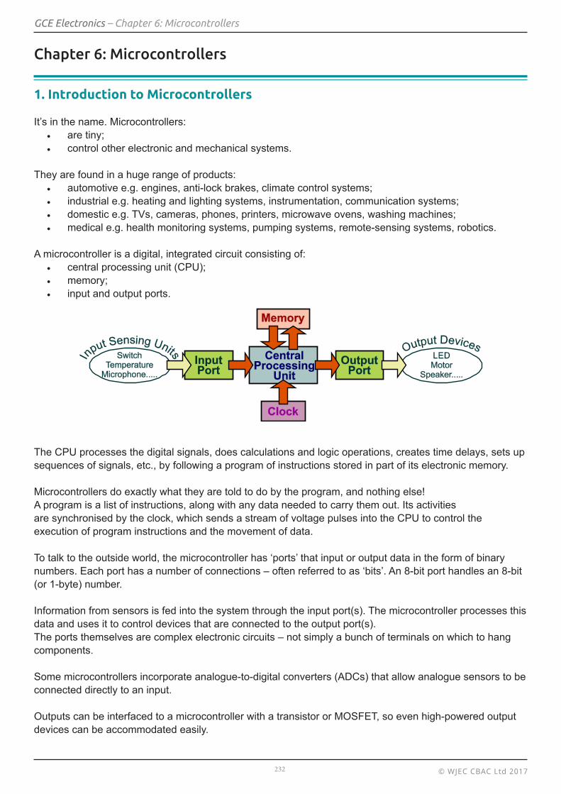
A microcontroller is a digital, integrated circuit consisting of: • central processing unit (CPU);• memory;• input and output ports.
The CPU processes the digital signals, does calculations and logic operations, creates time delays, sets up sequences of signals, etc., by following a program of instructions stored in part of its electronic memory.
Microcontrollers do exactly what they are told to do by the program, and nothing else!A program is a list of instructions, along with any data needed to carry them out. Its activitiesare synchronised by the clock, which sends a stream of voltage pulses into the CPU to control the execution of program instructions and the movement of data.
To talk to the outside world, the microcontroller has ‘ports’ that input or output data in the form of binary numbers. Each port has a number of connections – often referred to as ‘bits’. An 8-bit port handles an 8-bit (or 1-byte) number.
Information from sensors is fed into the system through the input port(s). The microcontroller processes this data and uses it to control devices that are connected to the output port(s).The ports themselves are complex electronic circuits – not simply a bunch of terminals on which to hang components.
Some microcontrollers incorporate analogue-to-digital converters (ADCs) that allow analogue sensors to be connected directly to an input.
Outputs can be interfaced to a microcontroller with a transistor or MOSFET, so even high-powered output devices can be accommodated easily.

© WJEC CBAC Ltd 2017233
GCE Electronics – Chapter 6: Microcontrollers
2. Programming a Microcontroller
A program sets out a sequence of actions which the microcontroller should take.The design process usually starts with a flowchart. This is a set of program commands which are repre-sented by icons that describe the program sequence. The shape of the icon indicates the type of action involved. The actions required are written inside the icons. The icons are then linked to show the flow of the program by arrowed lines called flow lines.
Some of the more common flowchart icons are described below:
Icons Name Typical use
Terminator Starting and finishing a flowchart.
Process Used where calculation or a delay is needed.
Decision Used to ask a question which can be answered ‘Yes’ or ‘No’. The route followed by the sequence depends on the answer.
Input/output Imports data from an input source or exports it to an output device.
3. Programming Languages
Unfortunately, microcontrollers do not understand English. They understand numbers. There’s the problem! We don’t speak in numbers, and they don’t understand English! There are two solutions, and both need some form of translator:
• We could write the program in English, or something close to it, and then have the result translated into numbers.
• We can think through the program design in English and then translate it ourselves into a language that is similar to numbers, known as ‘assembler’. From there, it is a swift and simple step for an electronic system to convert it into the numerical code that the microcontroller understands.
These two extremes are known as programming in a high-level language (something close to English) or in a low-level language (assembler).
Note:The information given above, in sections 1 and 3, will not be examined in any AS examinations.
© WJEC CBAC Ltd 2017234
GCE Electronics – Chapter 6: Microcontrollers
4. Graphic-based programming
Learning Objectives:
At the end of this topic you should be able to:• analyse a given flowchart;• design a flowchart to meet a given specification;• complete a flowchart template;• modify a given flowchart;• use the following operations in flowcharts:
• input/output data;• count pulses;• branch, conditionally and unconditionally;• test input data and data contained in variables;• use time delays;• perform arithmetic operations.
Converting a flowchart, icon by icon, into a fully fashioned program can be both difficult and time consuming. For this reason, user-friendly applications have been developed that use a graphics interface and do not require traditional programming skills.Flowchart icons are chosen from a menu and ‘dragged’ onto the computer screen. An editing window allows the contents to be translated into instructions, avoiding syntax errors. The flowchart can then be tested and edited.
Flowchart Control Programs
Currently available flowchart control systems include:• ‘Flowol’,• ‘Picaxe’• ‘Genie’ (part of ‘Circuit Wizard’)• ‘Flowcode’.
All allow on-screen simulation and download via a USB cable to a microcontroller on a dedicated interface circuit board.
Note:The activities in this chapter are written in generic format. Commercial programs vary in the way they are configured and in the functionality offered by the ‘drag-and-drop’ icons.The activities are intended to illustrate aspects of programming using flowchart control programs, rather than to perform a useful function. However, they can be extended and modified to satisfy ‘real-life’ requirements.Some flowchart control programs:
• use ‘Delay’ rather than ‘Wait’ to represent a time delay; • use ‘High’ or ‘Low’ to turn a single output on or off and ‘Outputs’ to turn multiple outputs on and off,
whilst others use ‘Outputs’ for both situations;• Use IN and OUT to read and write to inputs/outputs
Some flowchart control programs can be configured both to examine the state of the switch and execute the decision in a single icon. Others require that the state of the switch is examined in an Input icon, and then test the data in a subsequent Decision icon.

© WJEC CBAC Ltd 2017235
GCE Electronics – Chapter 6: Microcontrollers
Another difference between applications is that some distinguish between digital and analogue signals, or when comparing signals and use distinctive Decision icons for each.
Investigations
There are no specific investigations suggested in this chapter. Instead, the student should construct and test each of the following flowcharts, using any available flowchart control program. The student should ensure that the chosen microprocessor has a sufficient number of bits available on the input and output ports to satisfy the requirements of the flowchart.
Program 1: Outputting Data
Purpose:
This program:• switches on an LED, attached to the output port, for five seconds;• switches it off for two seconds;• then repeats the process over and over again.
Features:• Each ‘bit’ of the output port is controlled independently. Here, the program controls the device attached to bit 0, the LED.• The task of turning a device on for a period of time must be broken down into three stages:
• turn on the device;• leave it on for the required time, by adding a delay;• switch it off.
• This program needs no input from the real world. Once started, it simply runs regardless of external factors.
• To repeat the sequence indefinitely, the program ‘loops back’ to the beginning of the flowchart.
Note: Some flowchart programs will insert a ‘STOP’ icon by default even if the program loops back and repeats a sequence indefinitely. In this situation, the STOP will be ignored.
© WJEC CBAC Ltd 2017236
GCE Electronics – Chapter 6: Microcontrollers
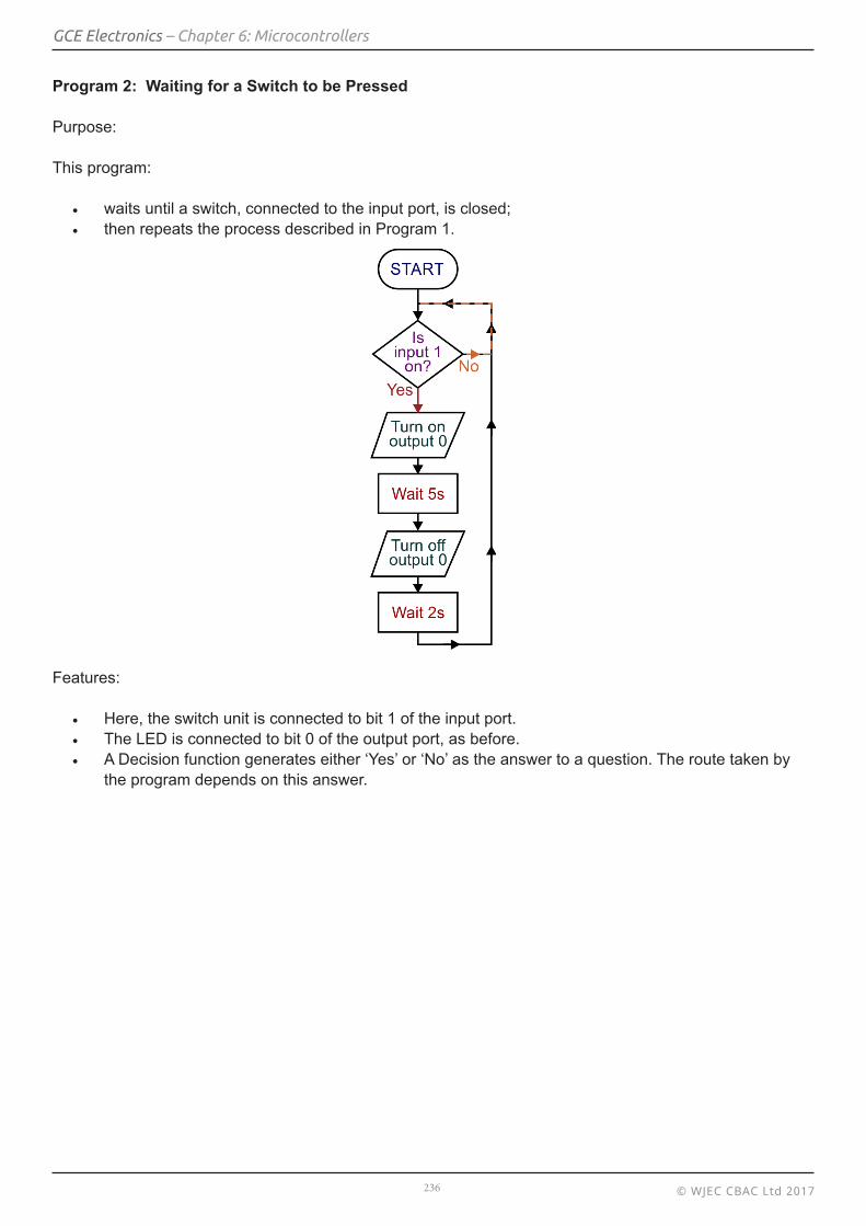
Program 2: Waiting for a Switch to be Pressed
Purpose:
This program:
• waits until a switch, connected to the input port, is closed;• then repeats the process described in Program 1.
Features:
• Here, the switch unit is connected to bit 1 of the input port.• The LED is connected to bit 0 of the output port, as before.• A Decision function generates either ‘Yes’ or ‘No’ as the answer to a question. The route taken by
the program depends on this answer.

© WJEC CBAC Ltd 2017237
GCE Electronics – Chapter 6: Microcontrollers
Program 3: Inputting Data
Purpose:
This program:• forms part of the security system for a building;• reads an entry code, six bits long, entered on a keypad;• releases the lock – a solenoid – only when the correct code is entered.
Features:
• The keypad is attached to Port A of the microcontroller.• The instruction ‘Read…’ means ’Examine the state of the port’ (i.e. check which bits are at logic 1
and which at logic 0).• Data from the read icon is stored in a variable called ‘input’. A variable is a memory location
identified by a name rather than an address.• The solenoid lock is attached to bit 0 of Port B. A logic 1 signal activates the lock.• The correct code is ‘00000101’ (in binary) or ‘5’ (in decimal).• The Decision function tests to see if ‘input’ contains the number ‘5’ (decimal) or ‘00000101’
(in binary).• If it does not, then the program returns to the beginning and waits until the correct code is entered.• When the correct code is entered, the solenoid lock is released by sending a logic 0 signal to bit 0 of
Port B (and to the rest of the port in this example).
(The program does not penalise the user for an incorrect entry. It could be extended to limit the number of attempts or impose a time penalty following an incorrect attempt.)

© WJEC CBAC Ltd 2017238
GCE Electronics – Chapter 6: Microcontrollers
Program 4: Inputting Analogue Data
Purpose:
Modern microcontrollers have at least one input port that can convert an analogue signal connected to it into a binary number, using a built-in analogue-to-digital converter (ADC).
This program:• monitors the temperature in a workshop using a temperature-sensing unit connected to analogue
input A0 (Port A, bit 0);• turns on an air-conditioning unit fan when the room temperature is above 35°C.
Features:
• Data from an analogue temperature-sensing unit is sent to an ADC built into the input port of the microcontroller. It produces a digital number between 0 and 255 which is stored automatically in the microcontroller memory.
• The Decision icon tests this number to see if it is greater than 35°C. If it is, the program follows the ‘Yes’ route and switches on a fan connected to the output port. When the answer is ‘No’, the fan is turned off (a necessary step in case previously it had been turned on).
• The program then returns to test the temperature again.
°

© WJEC CBAC Ltd 2017239
GCE Electronics – Chapter 6: Microcontrollers
Program 5: Inputting and Outputting
This topic is tackled in two stages:• the first examines the status of the switches concealed in the exits in a theatre in order to indicate
which one is opened;• the second adds an alarm function to warn when a door is opened.
Stage 1:
This program:• monitors six emergency exits in a theatre by checking switches attached to each;• identifies the door that was opened by lighting the appropriate LED on a display.
The flowchart is given below.
Features:
• Each switch is connected to one of bits 0 to 5 of Port A of the microcontroller and outputs logic 1 when the door is open.
• The status of the switches is stored in a variable called ‘door’ when Port A is ‘read’. • The LED display is attached to bits 0 to 5 of Port B.• When a Port B bit is at logic 1, the LED connected to it lights.
Stage 2:
This adds a requirement to check whether any door is opened. If a door is opened, the alarm pulses until it is closed. The LED display shows which door is open. When the door is closed, the alarm and LED turn off.

© WJEC CBAC Ltd 2017240
GCE Electronics – Chapter 6: Microcontrollers
In addition to the previous brief, it will now:• sound an alarm when any door is opened;• switch off the alarm and LED when the door is closed.
Features:
• The alarm is attached to bit 7 of Port B.• The first Decision function checks if a door has been opened.• The variable ‘alarm’ stores a binary number which both identifies the
open door and switches on the alarm.• The first Process icon creates this binary number.• The second Decision function checks if the door is still open.
• If it is, the program loops back, pulses the alarm again and displays the identity of the open door.
• If it is now closed, the program switches off the LED and alarm and loops back to the beginning.
For example:
The door switch connected to bit 2 of Port A is opened.• When Port A is ‘read’, ‘door’ stores the binary number 00000100 (= 4 in
decimal).• This is greater than zero, and so the program leaves the first Decision
icon by the ‘Yes’ route.• The variable ‘alarm’ is modified to 132 (decimal) or 10000100 (binary).• When sent to Port B, this lights the LED connected to bit 2 and switches
on the alarm connected to bit 7.• After a delay, the contents of ‘door’ are sent to Port B. This keeps the
LED lit but turns off the alarm, for one second.• If the door remains open, the program repeatedly takes the ‘No’ branch
from the second Decision icon and outputs 10000100. The LED stays on and the alarm continues to pulse.
• When the door is closed, the contents of ‘door’ changes to zero. The program leaves the second Decision icon via the ‘Yes’ route, changes the contents of ‘alarm’ to zero and sends this to Port B. The alarm and LED are turned off.
• The program returns to the beginning.

© WJEC CBAC Ltd 2017241
GCE Electronics – Chapter 6: Microcontrollers
Program 6: Counting and Testing
Purpose:
Microcontrollers are often used to count events, like an object breaking a light-beam on a conveyor belt. There are complications in this seemingly simple task. In particular, care must be taken to ensure that the system counts each event only once. This may mean adding a short delay before the program loops back.Once a specific number of objects have passed through the beam, and been placed in the box, another action, such as closing the box with the objects inside it, is carried out. The process then repeats.In this example, there are other tasks to take care of, not tackled in the following flowchart:
• replacing filled boxes with empty ones;• loading objects onto the conveyor;• placing objects into the box after being counted, etc.
Features:
• The current total count is stored in a variable called ‘count’.• When an event occurs, a Process icon is used to increment (add one to) this variable.• When six of these events have been detected, the program leaves the Decision icon by the ‘Yes’
route and closes the box.• In order to repeat the process, the ‘count’ variable must be reset to zero by revisiting the first
Process icon.

© WJEC CBAC Ltd 2017242
GCE Electronics – Chapter 6: Microcontrollers
Program 7: Traffic Count
Purpose:
Humans are not very good at monotonous tasks like counting the number of vehicles passing down a road over a long period of time. They fall asleep, lose concentration or forget the current total. Microcontrollers can be much more reliable. The aim of this program is to count vehicles by counting electronic pulses received from a pressure pad placed in the road.
When one hundred vehicles have been counted, the system gives outa loud ‘beep’ and resets to continue the count. All that the human hasto do is press a switch to acknowledge the ‘beep’ and keep a runningtotal of how many ‘beeps’ have occurred!
Features:
• The current total number of pulses received is stored in a variable called ‘total’.
• It is assumed that vehicles have two axles, so that two pulses are generated when a vehicle passes over the pressure pad.
• A Process icon is used to halve the number of pulses received (in the variable ‘total’) to count the number of vehicles, rather than axles, that passed over the pressure pad. The result is stored in a variable called ‘traffic’.
• A Decision icon is used to detect when one hundred vehicles have been detected. It switches on a buzzer, attached to bit 0 of the output port, and waits for the human to acknowledge it by monitoring a switch.
• When it is pressed, the ‘total’ and ‘traffic’ variables are reset and the count starts all over again.
© WJEC CBAC Ltd 2017243
GCE Electronics – Chapter 6: Microcontrollers
Program 8: Using Decision Icons to Create a Menu
Purpose:
The program offers a menu of different tasks.Each task is chosen by pressing a specific switch, attached to the input port.Decision icons identify which switch has been pressed and select the route through the flowchart accordingly.
The menu:• when switch X is pressed, a buzzer sounds;• when switch Y is pressed, an LED lights.
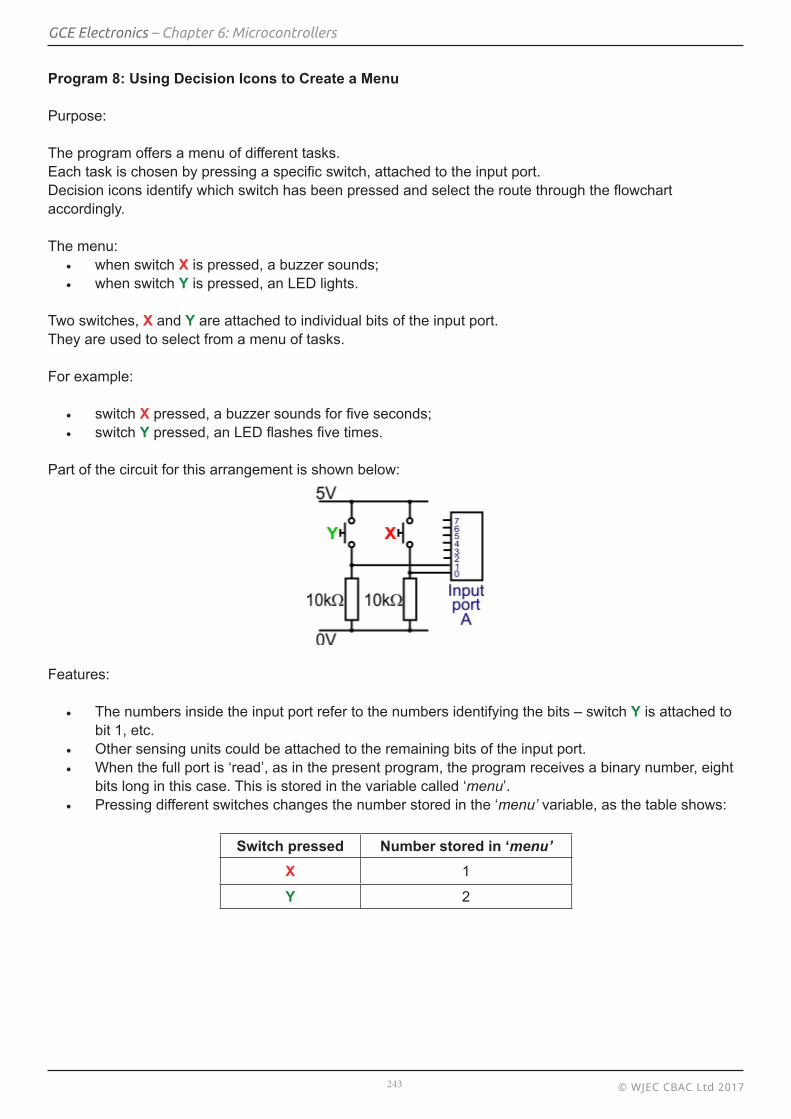
Two switches, X and Y are attached to individual bits of the input port.They are used to select from a menu of tasks.
For example:
• switch X pressed, a buzzer sounds for five seconds;• switch Y pressed, an LED flashes five times.
Part of the circuit for this arrangement is shown below:
Features:
• The numbers inside the input port refer to the numbers identifying the bits – switch Y is attached to bit 1, etc.
• Other sensing units could be attached to the remaining bits of the input port.• When the full port is ‘read’, as in the present program, the program receives a binary number, eight
bits long in this case. This is stored in the variable called ‘menu’.• Pressing different switches changes the number stored in the ‘menu’ variable, as the table shows:
Switch pressed Number stored in ‘menu’X 1
Y 2

© WJEC CBAC Ltd 2017244
GCE Electronics – Chapter 6: Microcontrollers
Features:
• When port A is ‘read’, a binary number is stored in the variable ‘menu’.• The value stored there depends on which switch is pressed.• The program follows the ‘No’ routes through the Decision boxes until it finds one that matches
the number stored in ‘menu’. Then it takes the ‘Yes’ route and performs the task specified for that selection.
• The program eventually returns to the start of the flowchart and awaits the next switch press.
© WJEC CBAC Ltd 2017245
GCE Electronics – Chapter 6: Microcontrollers
Program 9: Using Sub-routines
Sub-routines are sometimes referred to as procedures or macros.
Purpose:
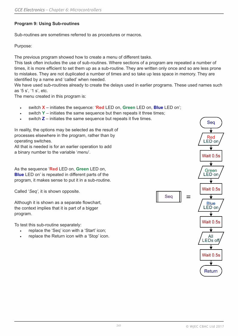
The previous program showed how to create a menu of different tasks.This task often includes the use of sub-routines. Where sections of a program are repeated a number of times, it is more efficient to set them up as a sub-routine. They are written only once and so are less prone to mistakes. They are not duplicated a number of times and so take up less space in memory. They are identified by a name and ‘called’ when needed.We have used sub-routines already to create the delays used in earlier programs. These used names such as ‘5 s’, ‘1 s’, etc.The menu created in this program is:
• switch X – initiates the sequence: ‘Red LED on, Green LED on, Blue LED on’;• switch Y – initiates the same sequence but then repeats it three times;• switch Z – initiates the same sequence but repeats it five times.
In reality, the options may be selected as the result ofprocesses elsewhere in the program, rather than byoperating switches.All that is needed is for an earlier operation to adda binary number to the variable ‘menu’.
As the sequence ‘Red LED on, Green LED on,Blue LED on’ is repeated in different parts of theprogram, it makes sense to put it in a sub-routine.
Called ‘Seq’, it is shown opposite.
Although it is shown as a separate flowchart,the context implies that it is part of a bigger program.
To test this sub-routine separately:• replace the ‘Seq’ icon with a ‘Start’ icon;• replace the Return icon with a ‘Stop’ icon.
© WJEC CBAC Ltd 2017246
GCE Electronics – Chapter 6: Microcontrollers
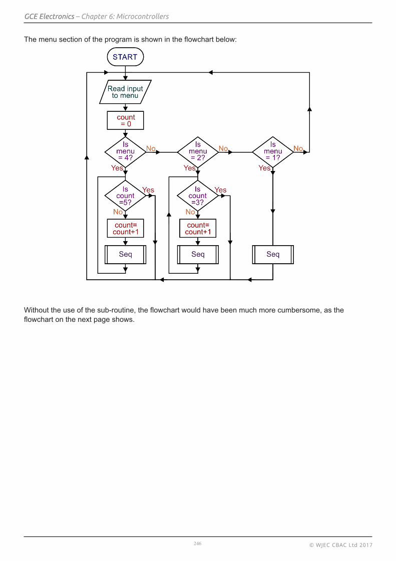
The menu section of the program is shown in the flowchart below:
Without the use of the sub-routine, the flowchart would have been much more cumbersome, as the flowchart on the next page shows.

© WJEC CBAC Ltd 2017247
GCE Electronics – Chapter 6: Microcontrollers

© WJEC CBAC Ltd 2017248
GCE Electronics – Chapter 6: Microcontrollers
Program 10: Performing Calculations
Purpose:
A cycling team is preparing for a competition.At the practice circuit, the team coach installsa lap counter to light a lamp when ten laps ofthe track have been completed.
The system uses a pressure pad, fitted to the track,which sends a signal to the lap counter every time abike wheel passes over it.
a) Complete the flowchart for the lap counter system by adding suitable flow lines.b) Identify a problem with the flowchart.c) Explain the roles of variables ‘A’ and ‘B’.

© WJEC CBAC Ltd 2017249
GCE Electronics – Chapter 6: Microcontrollers
a)
b) The program receives the first pulse when the front wheel hits the pressure pad at the beginning of the practice, followed shortly by the second pulse as the rear wheel hits the pressure pad. Both events increment the variables so that ‘A’ = 2 and ‘B’ = 1 right at the start. The light will come on after nine laps are completed, not ten.
c) A bicycle has two wheels and so the pressure pad sends two pulses to the lap counter each time one bicycle passes over it. Variable ‘A’ counts individual pulses – the number of wheels hitting the pressure pad. Variable ’B’, having half of the value stored in variable ‘A’, records the number of times a bicycle crosses the pressure pad.

© WJEC CBAC Ltd 2017250
GCE Electronics – Chapter 6: Microcontrollers
Program 11: Programming Servo Motors
Servos are included here for possible use in project work. The information given here will not be examined in any AS theory examinations.
Small servo motors can be very useful in electronic projects.They can, for example:
• move levers backwards and forwards to control steering in a model car;• operate signals, points and level crossings in model railway systems; • operate mechanisms in model cranes, toy tipper trucks, robotic animals and toy fairground rides.
The picture shows a typical mini servo of the type used in toys or models. It is an assembly of four parts: a DC motor, a gear reduction unit, a potentiometer and a control circuit.
It uses a potentiometer to monitor the rotational position of the shaft and hence determine which way the motor must turn to move the shaft to the required position. The shaft does not spin freely like a DC motor and, for most servos, can only turn up to maximum of 180°.
The control signal from a microcontroller determines the desired angular position of the servo shaft. Power applied to its DC motor turns the shaft to that position. The signal is in the form of a digital pulse which is repeated continuously at a frequency of 50 Hz. The length of the pulse, (the ‘mark’, M) determines how far the motor turns.The ‘space’, S, is determined in order to keep the period of the signal constant, usually 20 ms.This would give
For example, when M = 1.5 ms, the motor turns to the 90° position. Shorter pulses move it anti-clockwise, towards the 0° position, while longer pulses turn it clockwise, toward the 180° position. The following graph illustrates part of this signal when M = 1.5 ms:
Some flowchart control programs include built-in commands to rotate a servo to a desired position. For example, the icon shown opposite uses a predefined instruction to turn the servo to an angle of 60°,when the servo is controlled by output pin Q0.

© WJEC CBAC Ltd 2017251
GCE Electronics – Chapter 6: Microcontrollers
Converting the required angular position into the servo position parameter
In project work you may need to work out the position parameter, ‘k’, to enter into a program to make a servo turn to a certain angle.This can be done by entering the required angle into the equation:
Examples:
1. To turn the servo to an angle of 82°
so position parameter ‘143’ is entered in the servo command.
2. To turn the servo to an angle of 158°
so position parameter ‘207’ is entered in the servo command.
Program 12: Robot-arm Program
Purpose:
In a model production line, a robot arm moves repeatedly between two positions, the firstwhere the servo motor moves to an angle of 60°. After three seconds, it then moves to anangle of 120° and waits there for three seconds. The movement then repeats indefinitely.
Features:
• The ‘Servo_125’ command generates a pulse train in which the pulse has a duration of 0.125 ms with a period of 20 ms.
• The ‘Servo_175’ command generates a pulse train in which the pulse has a duration of 0.175 ms with a period of 20 ms.
Servo Position parameter, k = angle1.2 + 75
82k 75 143.31.2
= + =
158k 75 206.71.2
= + =
© WJEC CBAC Ltd 2017252
GCE Electronics – Chapter 6: Microcontrollers
Exercise 6.1
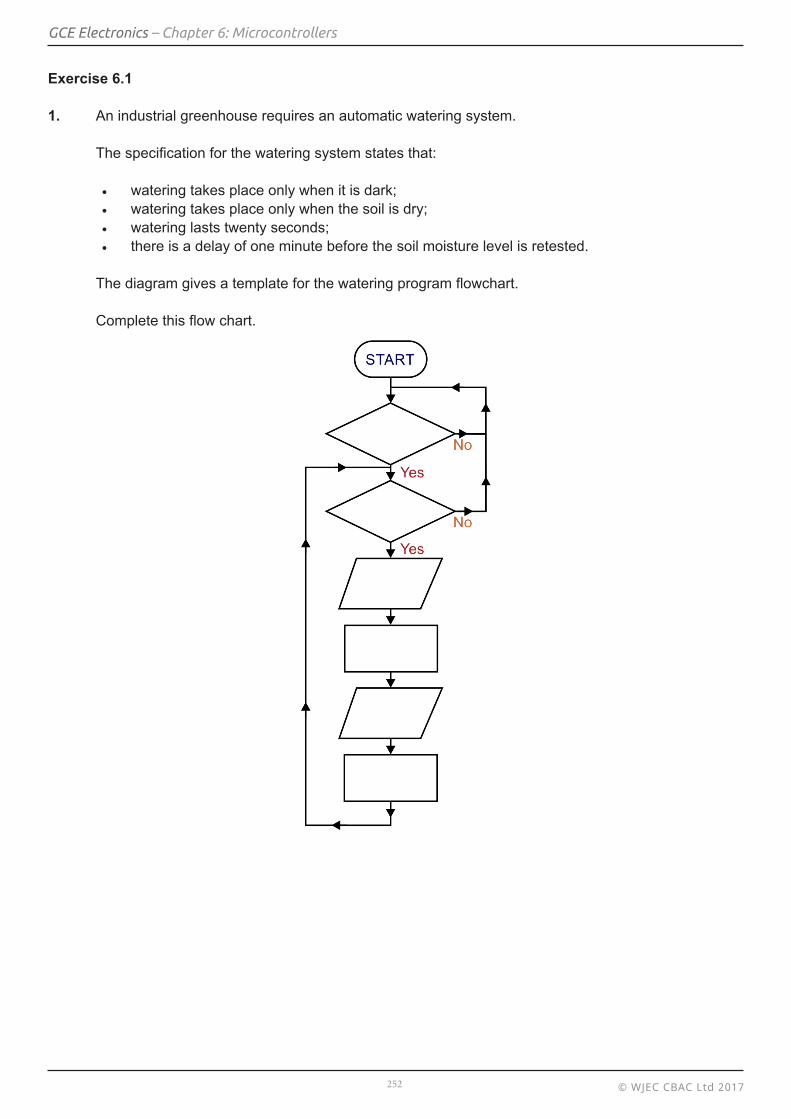
1. An industrial greenhouse requires an automatic watering system.
The specification for the watering system states that:
• watering takes place only when it is dark;• watering takes place only when the soil is dry;• watering lasts twenty seconds;• there is a delay of one minute before the soil moisture level is retested.
The diagram gives a template for the watering program flowchart.
Complete this flow chart.

© WJEC CBAC Ltd 2017253
GCE Electronics – Chapter 6: Microcontrollers
2. A railway bridge crosses over a narrow road. Traffic takes turns to pass under the bridge, controlled by two sets of traffic lights.
Each set goes through the following sequence:
The lights in set ‘X’ are identified as RedX, AmberX and GreenX. Similarly, those in set Y are called RedY, AmberY and GreenY.
Both sets of lights, ‘X’ and ‘Y’, are controlled and synchronised by a microcontroller-based system.
a) Complete the flowchart for this control system.

© WJEC CBAC Ltd 2017254
GCE Electronics – Chapter 6: Microcontrollers
b) To make the system more ‘intelligent’, sensors are placed on the approaches to the junction, at the points labelled ‘S’.
The aim is that the lights change to allow the opposite flow of traffic only if a vehicle is detected approaching the other side of the junction.
The incomplete flowchart given earlier is shown below. Modify it by adding a suitably labelled Decision box, and flow line(s) to show how a signal from sensor SX could be used to trigger a change in the traffic lights.

© WJEC CBAC Ltd 2017255
GCE Electronics – Chapter 6: Microcontrollers
3. A microcontroller is used to control a level crossing on a model railway.
Reed switches are placed on the track before and after the level crossing. A magnet on the underside of a train operates the first reed switch when the train passes. This causes the barrier to be lowered through 90° and a lamp to flash on and off continuously.
The following commands are available:• ‘servo 75’ – holds the barrier in the horizontal position;• ‘servo 150’ – holds the barrier in the vertical position.
When the train has passed the level crossing, the second reed switch is triggered, the barrier returns to the upright position, and the lamp switches off.
a) Complete the flowchart.
b) When the system was tested, it was found that the lamp did not flash on and off for as long as expected. State the reason for this and suggest how the problem can be rectified.
…………………………………………………………….. …………………………………………………………….. …………………………………………………………….. …………………………………………………………… …………………………………………………………….. …………………………………………………………….. …………………………………………………………… ……………………………………………………………..