1 34apps.sd.gov/hc65c2c/ebs/lettings/electronicplans/05y7...estimate of quantities state of project...
TRANSCRIPT
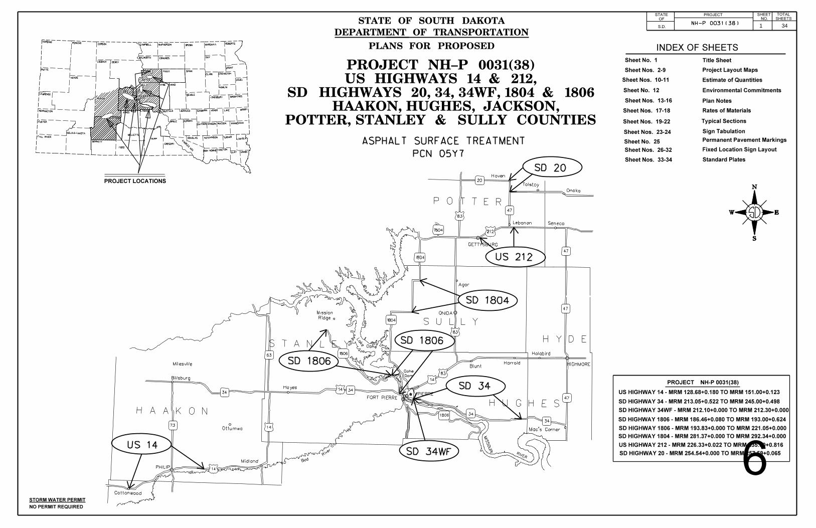
1 34
6

2 34

3 34
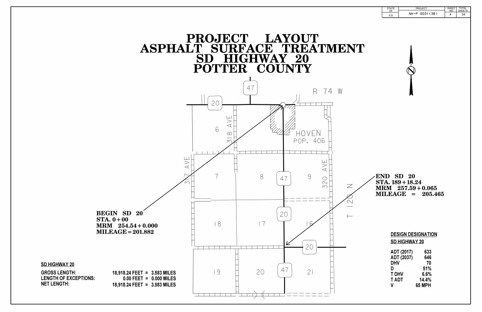
4 34

5 34
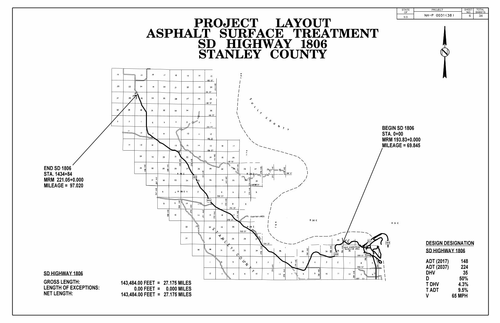
6 34

7 34

8 34

9 34

ESTIMATE OF QUANTITIES PROJECTSTATE OFSOUTH
DAKOTA NH-P 0031(38)SHEET
TOTALSHEETS
ESTIMATE OF QUANTITIES
The quantities of asphalt for surface treatment and cover aggregate are based on the rates shown in the Rates of Materials. This is only an estimate. The actual application rates of materials will be determined by mix design as stated in these plans. The mix design rates may vary from the estimated rates stated in the Rates of Materials depending on the aggregate source and the variation in gradation and flakiness index. The application rates may also be adjusted in the field due to results of gradations, flakiness index, and differing surface conditions. Pay quantities will be those actually used even though they may vary significantly from plans estimates.
SPECIFICATION Revised 01/28/2019 EFFJr.
Standard Specifications for Roads and Bridges, 2015 Edition and Required Provisions, Supplemental Specifications, and Special Provisions as included in the Proposal.
10 34

ESTIMATE OF QUANTITIES (FOR INFORMATION ONLY) PROJECTSTATE OFSOUTH
DAKOTA NH-P0031(38)SHEET
TOTALSHEETS
* -Denotes Non-Participating ** - Actual quantities but doubled for two applications in Estimate of Quantities table.
BID ITEM NUMBER ITEM US14 SD34 SD1806 SD1806 SD1804 US 212 SD 20*
034WF QUANTITY UNIT
009E0010 MobilizationLump Sum
Lump Sum
Lump Sum
Lump Sum
Lump Sum
Lump Sum
Lump Sum
Lump Sum LUMP SUM LS
330E0300 SS-1h or CSS-1h Asphalt for Fog Seal 81.1 118.5 30.3 94.9 43.6 40.4 16.4 0.5 425.7 Ton
330E3000 Sand for Fog Seal 50.0 10.0 10.0 10.0 10.0 50.0 50.0 5.0 195.0 Ton
360E0020 AE150S Asphalt for Surface Treatment 398.0 619.3 121.7 487.8 188.2 - - 3.1 1,818.1 Ton
360E0042 CRS-2P Asphalt for Surface Treatment - - - - - 201.2 78.6 - 279.8 Ton
360E1010 Type 1A Cover Aggregate - - - - - 1859.8 - - 1,859.8 Ton
360E1010 Type 1A Cover Aggregate - - - - - - 699.3 - 699.3 Ton
360E1020 Type 1B Cover Aggregate - - 1068.3 - - - - - 1,068.3 Ton
360E1020 Type 1B Cover Aggregate - - - 4208.9 - - - - 4,208.9 Ton
360E1020 Type 1B Cover Aggregate - - - - 1623.5 - - - 1,623.5 Ton
360E1020 Type 1B Cover Aggregate - 5724.5 - - - - - - 5,724.5 Ton
360E1020 Type 1B Cover Aggregate 3433.3 - - - - - - - 3,433.3 Ton
360E1020 Type 1B Cover Aggregate - - - - - - - 29.0 29.0 Ton
633E1200 Waterborne Pavement Marking Paint with High Grade Polymer, White 1111 1575 323 1342 542 445 128 4 5,470.0 Gal
633E1205 Waterborne Pavement Marking Paint with High Grade Polymer,Yellow 391 465 113 382 79 60 49 1 1,540.0 Gal
633E6005 Pavement Marking Masking, 5" 5,850.0 - 7,160.0 - - - 10,090.0 - 23,100.0 Ft **
633E6020 Pavement Marking Masking, 25" - - 166.0 - - - 79.0 - 245.0 Ft **
633E6030 Pavement Marking Masking, Arrow 4 - 8 - - - - - 12.0 Each **
633E6045 Pavement Marking Masking, Railroad Crossing 2 - - - - - - - 2.0 Each **
634E0010 Flagging 250.0 150.0 50.0 250.0 100.0 125.0 150 0.0 1,075.0 Hour
634E0020 Pilot Car 65.0 40.0 15.0 65.0 25.0 30.0 40.0 0.0 280.0 Hour
634E0110 Traffic Control Signs 670.6 750.8 576.9 750.8 536.8 536.8 365.2 160.0 4,347.9 SqFt
634E0120 Traffic Control, MiscellaneousLump Sum
Lump Sum
Lump Sum
Lump Sum
Lump Sum
Lump Sum
Lump Sum
Lump Sum LUMP SUM LS
634E0630 Temporary Pavement Marking 44.590 63.362 13.068 54.350 21.876 18.012 7.166 0.3 222.7 Mile
998E0100 Railroad Protective InsuranceLump Sum
Lump Sum - - - - - - LUMP SUM LS
11 34
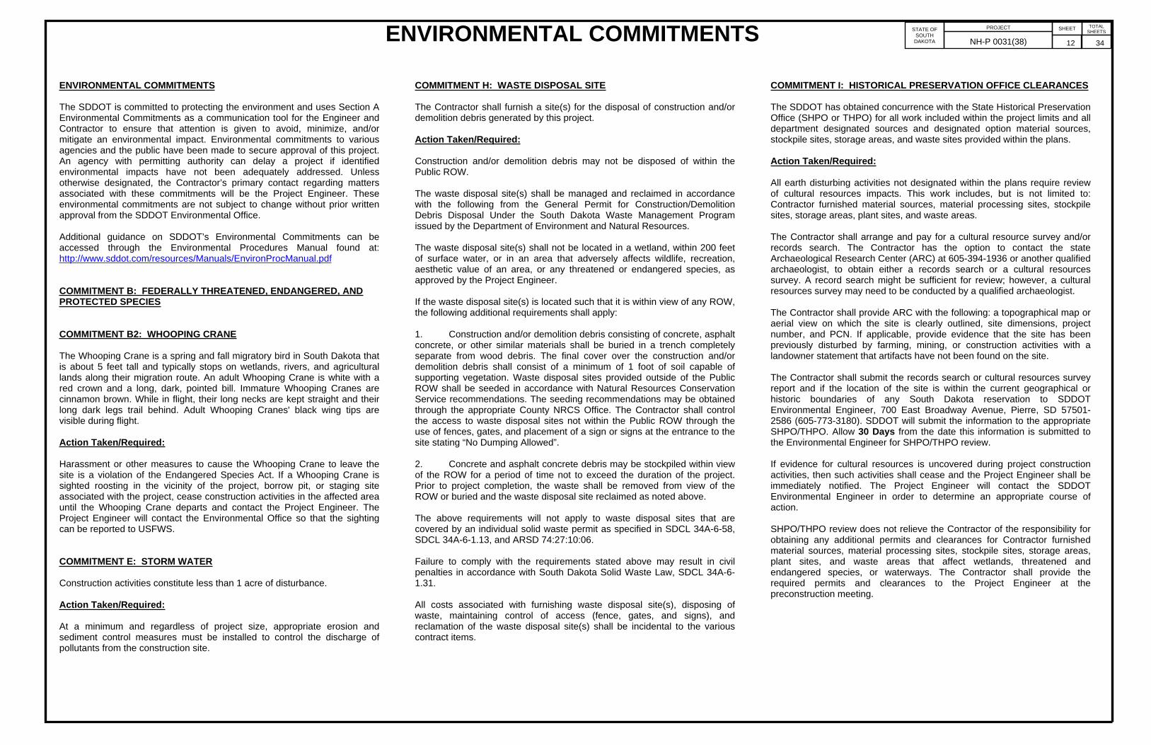
ENVIRONMENTAL COMMITMENTS PROJECTSTATE OFSOUTH
DAKOTA NH-P 0031(38)SHEET
TOTALSHEETS
ENVIRONMENTAL COMMITMENTS
The SDDOT is committed to protecting the environment and uses Section A Environmental Commitments as a communication tool for the Engineer and Contractor to ensure that attention is given to avoid, minimize, and/or mitigate an environmental impact. Environmental commitments to various agencies and the public have been made to secure approval of this project. An agency with permitting authority can delay a project if identified environmental impacts have not been adequately addressed. Unless otherwise designated, the Contractor’s primary contact regarding matters associated with these commitments will be the Project Engineer. These environmental commitments are not subject to change without prior written approval from the SDDOT Environmental Office.
Additional guidance on SDDOT’s Environmental Commitments can be accessed through the Environmental Procedures Manual found at: http://www.sddot.com/resources/Manuals/EnvironProcManual.pdf
COMMITMENT B: FEDERALLY THREATENED, ENDANGERED, AND PROTECTED SPECIES
COMMITMENT B2: WHOOPING CRANE
The Whooping Crane is a spring and fall migratory bird in South Dakota that is about 5 feet tall and typically stops on wetlands, rivers, and agricultural lands along their migration route. An adult Whooping Crane is white with a red crown and a long, dark, pointed bill. Immature Whooping Cranes are cinnamon brown. While in flight, their long necks are kept straight and their long dark legs trail behind. Adult Whooping Cranes' black wing tips are visible during flight.
Action Taken/Required:
Harassment or other measures to cause the Whooping Crane to leave the site is a violation of the Endangered Species Act. If a Whooping Crane is sighted roosting in the vicinity of the project, borrow pit, or staging site associated with the project, cease construction activities in the affected area until the Whooping Crane departs and contact the Project Engineer. The Project Engineer will contact the Environmental Office so that the sighting can be reported to USFWS.
COMMITMENT E: STORM WATER
Construction activities constitute less than 1 acre of disturbance.
Action Taken/Required:
At a minimum and regardless of project size, appropriate erosion and sediment control measures must be installed to control the discharge of pollutants from the construction site.
COMMITMENT H: WASTE DISPOSAL SITE
The Contractor shall furnish a site(s) for the disposal of construction and/or demolition debris generated by this project.
Action Taken/Required:
Construction and/or demolition debris may not be disposed of within the Public ROW.
The waste disposal site(s) shall be managed and reclaimed in accordance with the following from the General Permit for Construction/Demolition Debris Disposal Under the South Dakota Waste Management Program issued by the Department of Environment and Natural Resources.
The waste disposal site(s) shall not be located in a wetland, within 200 feet of surface water, or in an area that adversely affects wildlife, recreation, aesthetic value of an area, or any threatened or endangered species, as approved by the Project Engineer.
If the waste disposal site(s) is located such that it is within view of any ROW, the following additional requirements shall apply:
1. Construction and/or demolition debris consisting of concrete, asphalt concrete, or other similar materials shall be buried in a trench completely separate from wood debris. The final cover over the construction and/or demolition debris shall consist of a minimum of 1 foot of soil capable of supporting vegetation. Waste disposal sites provided outside of the Public ROW shall be seeded in accordance with Natural Resources Conservation Service recommendations. The seeding recommendations may be obtained through the appropriate County NRCS Office. The Contractor shall control the access to waste disposal sites not within the Public ROW through the use of fences, gates, and placement of a sign or signs at the entrance to the site stating “No Dumping Allowed”.
2. Concrete and asphalt concrete debris may be stockpiled within view of the ROW for a period of time not to exceed the duration of the project. Prior to project completion, the waste shall be removed from view of the ROW or buried and the waste disposal site reclaimed as noted above.
The above requirements will not apply to waste disposal sites that are covered by an individual solid waste permit as specified in SDCL 34A-6-58, SDCL 34A-6-1.13, and ARSD 74:27:10:06.
Failure to comply with the requirements stated above may result in civil penalties in accordance with South Dakota Solid Waste Law, SDCL 34A-6-1.31.
All costs associated with furnishing waste disposal site(s), disposing of waste, maintaining control of access (fence, gates, and signs), and reclamation of the waste disposal site(s) shall be incidental to the various contract items.
COMMITMENT I: HISTORICAL PRESERVATION OFFICE CLEARANCES
The SDDOT has obtained concurrence with the State Historical Preservation Office (SHPO or THPO) for all work included within the project limits and all department designated sources and designated option material sources, stockpile sites, storage areas, and waste sites provided within the plans.
Action Taken/Required:
All earth disturbing activities not designated within the plans require review of cultural resources impacts. This work includes, but is not limited to: Contractor furnished material sources, material processing sites, stockpile sites, storage areas, plant sites, and waste areas.
The Contractor shall arrange and pay for a cultural resource survey and/or records search. The Contractor has the option to contact the state Archaeological Research Center (ARC) at 605-394-1936 or another qualified archaeologist, to obtain either a records search or a cultural resources survey. A record search might be sufficient for review; however, a cultural resources survey may need to be conducted by a qualified archaeologist.
The Contractor shall provide ARC with the following: a topographical map or aerial view on which the site is clearly outlined, site dimensions, project number, and PCN. If applicable, provide evidence that the site has been previously disturbed by farming, mining, or construction activities with a landowner statement that artifacts have not been found on the site.
The Contractor shall submit the records search or cultural resources survey report and if the location of the site is within the current geographical or historic boundaries of any South Dakota reservation to SDDOT Environmental Engineer, 700 East Broadway Avenue, Pierre, SD 57501-2586 (605-773-3180). SDDOT will submit the information to the appropriate SHPO/THPO. Allow 30 Days from the date this information is submitted to the Environmental Engineer for SHPO/THPO review.
If evidence for cultural resources is uncovered during project construction activities, then such activities shall cease and the Project Engineer shall be immediately notified. The Project Engineer will contact the SDDOT Environmental Engineer in order to determine an appropriate course of action.
SHPO/THPO review does not relieve the Contractor of the responsibility for obtaining any additional permits and clearances for Contractor furnished material sources, material processing sites, stockpile sites, storage areas, plant sites, and waste areas that affect wetlands, threatened and endangered species, or waterways. The Contractor shall provide the required permits and clearances to the Project Engineer at the preconstruction meeting.
12 34

PROJECTSTATE OFSOUTH
DAKOTANH-P0031(38)
SHEETNO.
TOTALSHEETS
ENGINEER NOTIFICATION
The Contractor is required to notify the Pierre Area Engineer (Dean VanDeWiele (605)773-5294) at least 10 days prior to beginning asphalt surface treatment operations.
SEQUENCE OF OPERATIONS
The Contractor shall submit a proposed sequence of operations for the Engineer's review and approval at least two weeks prior to the preconstruction meeting.
The contractor shall schedule his operation to ensure that the Asphalt Surface Treatment on the section of highway 34 is performed after the work is complete for PCN i4XT (Inslope Drop-Off Repair). The completion date for PCN i4XT is scheduled for July 12, 2019. It will be the contractors responsibility to contact the contractor for PCN i4XT (Morris, Inc. 605-223-2585) and coordinate operations accordingly.
The Contractor shall modify the sequence of operation during the application of the asphalt surface treatment if any unforeseen circumstances occur that affect the installation or quality of the asphalt surface treatment. Circumstances that may affect the installation include, but are not limited to, weather, 24 hour temperatures, and traffic. These modifications shall be accomplished by the Contractor at no expense to the State and to the satisfaction of the Engineer.
The following sequence is provided, and is intended as a guide only, to the Contractor to aid in planning their sequence of operations and is not inclusive of all work activities.
1. Install fixed location ground mounted traffic control devices.
2. Place temporary pavement marking not more than 24 hours prior to chip seal.
3. Apply asphalt surface treatment. The application of the asphalt and aggregate shall cease at least one hour prior to sunset each day. Once work begins in a given lane each day, the Contractor will stay in that lane and will not be allowed to place asphalt surface treatment in the adjacent lane unless preapproved by the Engineer.
4. Remove plastic covers from temporary flexible vertical markers (tabs) after application of the chip seal and prior to nightfall.
5. Broom chip sealed areas each morning following chip seal application.
6. Apply fog seal.
7. Remove plastic covers from temporary flexible vertical markers (tabs) after application of the fog seal and prior to nightfall.
8. Immediately prior to application of the permanent pavement marking, the areas to be painted shall be broomed or blown off with high pressure compressed air. (If a high pressure air device is used to clean the pavement surface, it shall be capable of sustaining continuous high pressure for the duration of the pavement marking process.)
9. Complete the pavement marking.
10. Remove temporary flexible vertical markers (tabs) within the seven day time period specified in the Temporary Pavement Marking section of the plans.
11. Remove traffic control devices.
BRIDGE ENDS AND APPROACH SLABS
Asphalt surface treatment and Fog Seal shall not be placed on any bridge and/or bridge approach slabs. Any emulsion or cover aggregate found to be on bridges or approach slabs after final brooming shall be removed by the Contractor as directed by the Engineer at no cost to the Department.
Material used to cover and protect these areas shall be removed and disposed of properly after the application of the asphalt surface treatment. When the material is removed, the asphalt surface treatment that does not stay adhered to the material shall be removed from the road surface.
All joints at bridge ends including asphalt plug joints, membrane sealant, and strip seal glands along the project shall be masked and/or protected the entire length prior to Asphalt Surface Treatment operations. This protection shall remain in place until completion of the fog seal and any final brooming operations. The protection shall then be removed and any loose material cleaned out of each of the gland areas. Any damage to the glands caused by the asphalt surface treatment operations shall be repaired at no expense to the State. All costs related to this work shall be incidental to the various contract items.
The anticipated bridge locations are listed in the table below.
Structure No. 36-145-015 US 14 MRM 131.97
Structure No. 28-122-513 US 14 MRM 136.81
Structure No. 28-131-503 US 14 MRM 138.20
Structure No. 28-162-490 US 14 MRM 141.65
Structure No. 28-195-480 US 14 MRM 145.16
Structure No. 28-212-477 US 14 MRM 146.88
Structure No. 28-234-477 US 14 MRM 149.03
Structure No. 33-156-135 SD 34 MRM 214.76
Structure No. 33-178-141 SD 34 MRM 217.04
Structure No. 33-245-152 SD 34 MRM 223.87
Structure No. 33-246-153 SD 34 MRM 223.98
Structure No. 33-322-176 SD 34 MRM 232.23
SHOULDER WORKPrior to construction, Department of Transportation Maintenance Forces will spray the shoulders to kill existing vegetation. It will be the Contractor's responsibility to notify the State a minimum of thirty days prior to starting work on the shoulders of the highway. The State assumes no responsibility for the effectiveness of the herbicide applied.
Vegetation and accumulated material on or adjacent to the existing roadway edge shall be removed to the satisfaction of the Engineer prior to asphalt surface treatment.
Shoulder work shall be incidental to other contract items. Separate measurement and payment will not be made.
BROOMINGAll material shall be broomed off of bridges and curb & gutter areas adjacent to the bridges. No material shall be broomed under the guardrail, including the 3 cable guardrail or into the drop inlets. Material from the curb & gutter areas of the bridges, from guardrail areas of the bridges, and from drop inlets shall be disposed of in a manner satisfactory to the Engineer.
No material shall be broomed into the ditches or on the boulevards in residential and commercial areas where the adjacent landowner conducts the mowing of the right-of-way. This material shall be disposed of in a manner satisfactory to the Engineer.
Material that is broomed onto the roadway inslopes shall not be left in piles or windrows. The material shall be evenly distributed at a height that will not hinder mowing operations or cause dispersion of the material into the traveled roadway when passed over with a mower.
Anticipated areas, other than the bridge areas stated above, that will require either removal of the chips with a pickup sweeper or additional dispersal of the chips with the rotary powered broom are:
ROUTE LOCATION
US 14 Curb & gutter, residential and commercial areas in the City of Philip.
SD 20 Curb & gutter, residential and commercial areas in the City of Hoven.
SD 34WF Commercial areas in the City of Pierre.
This list may not be complete. Additional areas may need attention as directed by the Engineer.
ASPHALT FOR SURFACE TREATMENT
AE-150 Asphalt for Surface Treatment shall be used for US 14 & SD 34, 1804 and 1806 portions of the project.
CRS-2P Asphalt for Surface Treatment shall be used for US 212 & SD 20 portions of the project.
The asphalt for surface treatment that is delivered for use on this contract shall be used in the order it is received. Storage of asphalt for surface treatment shall only be allowed at the end of the work day. The material that is placed in storage shall be the first material used the following day.
Asphalt Surface Treatment shall not be applied to Rumble Bar areas prior to Stop Signs, however these areas shall be fog sealed.
Application of the asphalt surface treatment shall be applied to the widths specified in the plans. The Contractor will have to consider the width of overlap at centerline to obtain the total width specified. A gap at centerline between surface treatment passes will not be allowed.
COVER AGGREGATE
Type 1A Cover Aggregate shall be used for US 212 & SD 20 portions of the project.
Type 1B Cover Aggregate shall be used for US 14 & SD 34, 1804 and 1806 portions of the project.
After the aggregate stockpile has been produced, the Contractor shall submit an aggregate sample to the asphalt supplier a minimum of 14 days prior to
13 34

PROJECTSTATE OFSOUTH
DAKOTANH-P0031(38)
SHEETNO.
TOTALSHEETS
COVER AGGREGATE(Continued)
starting the project to allow time to evaluate the compatibility and design of the surface treatment. A copy of the test results shall be submitted to the Engineer and Bituminous Engineer for approval prior to starting the asphalt surface treatment work.
The Contractor shall continue chip spreader progress, forward, thru theasphalt application at any end where work will be temporarily shut down fora time greater than 5 minutes, to allow for satisfactory uniform rolling of theplaced aggregate. The Contractor shall not allow the chip spreader, trucks, rollers or other equipment to lie dormant on the aggregate while transitioningbetween asphalt distributor loads and or any other temporary shutdown ofproduction, before uniform rolling is complete.
All passes of the rollers shall be completed within 8 minutes of application ofthe CRS-2P Asphalt for Surface Treatment.
Quality tests on the Cover Aggregate for abrasion and soundness are required by specification. The Contractor shall notify the Pierre Area Office prior to sampling and a representative from the Pierre Area Office shall witness all sampling of aggregates to be submitted to the Central Testing Laboratory for quality testing. Satisfactory test results for the Cover Aggregate shall be obtained prior to its use on the project.
FOG SEAL
A CSS-1h or SS-1h emulsion shall be used for the fog seal application. A water-to-emulsion rate of 1:1 should be used for the Fog Seal application.
Fog Seal will be placed on all the routes on this contract. The fog seal shall be placed following the completion of the asphalt surface treatment and prior to the placement of the permanent pavement marking.
Application of the fog seal shall begin no earlier than the morning following application of the chip seal but no later than four days after the application of each day’s chip seal.
Immediately prior to the applications of the fog seal the Contractor will be required to broom the entire width of the chip seal. In addition, the rumble strips shall be thoroughly broomed clean prior to the application of the fog seal.
SAND FOR FOG SEAL
The Contractor shall plan the fog seal operation to allow adequate cure time for the fog seal and to minimize/eliminate the need to apply blotting sand to the fog seal.
A small quantity of Blotting Sand is set up, for each respective route to be Fog Sealed, to be used as directed by the Engineer at locations of high traffic volumes, such as intersecting state or county highways, that traffic cannot be stopped from crossing. The Contractor will be required to keep traffic off all other areas until the Fog Seal has cured sufficiently as to not stick to tires.
If adequate cure time for the Fog Seal is not available, to facilitate traffic, the Contractor shall be allowed to place a minimum sufficient amount of blotting sand on the fog seal to allow traffic to cross the uncured portion of the fog seal, as permitted by the Engineer.
Blotting sand for Fog Seal is only intended to be placed for accesses to businesses, intersection crossings, and as determined by the Engineer to facilitate traffic movements. Blotting sand will not be placed to accelerate the Contractor’s schedule.
Blotting sand that is applied shall be broomed off the surface of the roadway once the fog seal has sufficiently cured as determined by the Engineer.
Blotting sand for fog seal shall conform to Specification Section 879.1 B.
Prior to hauling, Blotting Sand shall be screened to minimize segregation, eliminate oversize, and effectively breakup or discard material bonded into chunks.
All costs for supplying, hauling, placing, and brooming the blotting sand shall be incidental to the contract unit price per ton for “Sand for Fog Seal”.
GENERAL MAINTENANCE OF TRAFFIC
Traffic shall be maintained in the driving lanes. Use of the shoulder as a driving lane will not be permitted. Any damage to the shoulder due to rerouted traffic or Contractor’s equipment shall be repaired at no expense to the State.
All materials and equipment shall be moved to a minimum distance of 30 feet from the edge of the traveled lanes during nights, weekends, and other non-working hours.
If operations exist where the traveling public will be delayed at a flagging station more than 5 minutes, it is required that the flaggers and pilot car operators all have radio or telephone contact with one another. This equipment is to be used to assist with Traffic movement in the event that an emergency vehicle such as ambulance, police or fire vehicles need to pass through the project in an expedient manner.
Highway equipment working within traffic or adjacent to traffic shall, at all times, display a flashing or revolving amber light to warn the traveling public.
Sufficient traffic control devices have been included in these plans to sign two workspaces per route. No additional payment will be made if the Contractor elects to work on additional sites simultaneously.
TRAFFIC CONTROL FOR ASPHALT SURFACE TREATMENT
All traffic control sign fixed locations shall be marked in the field by the Contractor and verified by the Engineer prior to installation.
Work activities will be conducted during daylight hours only.
Removing, relocating, covering, salvaging and resetting of existing traffic control devices, including delineation, shall be the responsibility of the Contractor. Cost for this work shall be incidental to the contract unit prices for the various items unless otherwise specified in the plans. Any delineators and signs damaged or lost shall be replaced by the Contractor at no cost to the State.
The Contractor shall furnish, install, maintain, and remove TRUCK CROSSING signs daily. The TRUCK CROSSING signs shall be displayed at all times when haul vehicles are hauling material. When hauling conditions no longer exist, the signs shall be covered or removed from view. The exact number and location shall be determined on construction. Payment for additional signs will be based on the contract unit price per square foot for Traffic Control Signs.
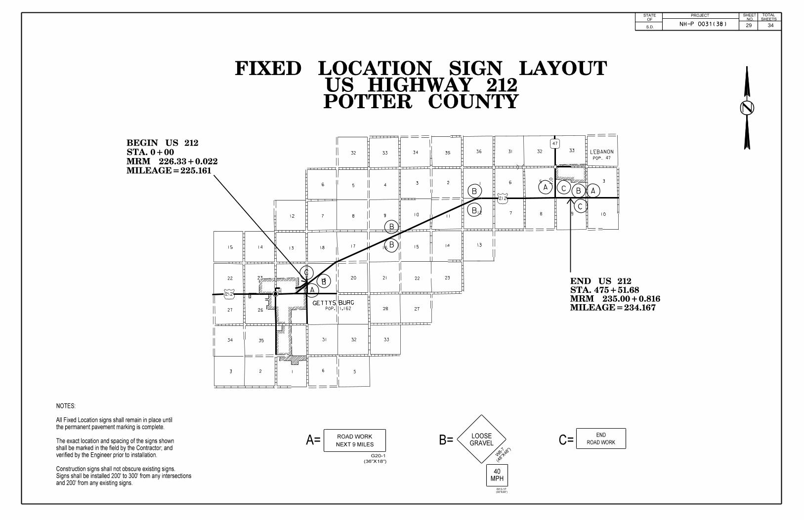
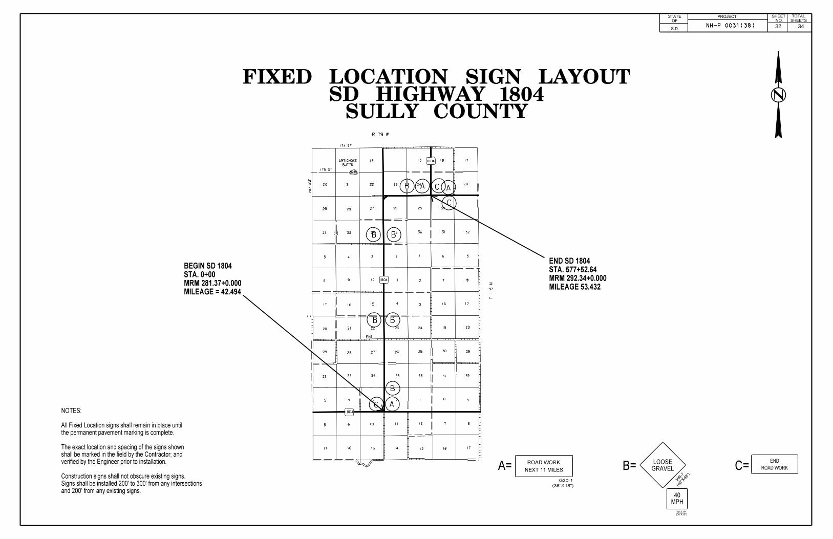
The Contractor shall furnish, install, and maintain LOOSE GRAVEL signs with 40 MPH advisory speed plaques upon start of surface treatment operations at each end of the segment and on either side of intersecting asphalt roads and major intersections as determined by the Engineer. In addition, LOOSE GRAVEL signs with 40 MPH advisory speed plaques shall be installed at no more than 4 mile intervals throughout each segment. The 40 MPH advisory speed plaque should not be installed with LOOSE GRAVEL signs in areas where the posted speed limit is less than 40 MPH. LOOSE GRAVEL sign and 40 MPH advisory speed plaques shall be covered or removed from view when they are not applicable.
ROAD WORK NEXT XX MILES, LOOSE GRAVEL, and END ROAD WORK signs are the only signs that need to be mounted on fixed location breakaway sign supports, as shown on the plan layout. ROAD WORK AHEAD, FLAGGER, ONE LANE ROAD AHEAD, and TRUCK CROSSING signs may be mounted on portable supports. Any other signs used may be mounted on portable supports as long as the duration is not more than 3 calendar days. If the duration is more than 3 calendar days, the signs shall be mounted on fixed location breakaway sign supports. The bottom of signs on portable supports shall not be less than 7 feet above the pavement in urban areas, and 1 foot above the pavement in rural areas. Signs mounted on portable supports shall be moved as necessary to keep current with the work activities.
Fixed location signing placed more than 4 calendar days prior to the start of construction shall be covered or laid down until the time of construction. The covers must be approved by the Engineer prior to installation. The cost of materials, labor, and equipment necessary to complete this work shall be incidental to other contract items. No separate payment will be made.
Traffic shall be maintained on the driving lanes. Use of the shoulder as a driving lane will not be permitted. Any damage to the shoulder due to rerouted traffic or Contractor’s equipment shall be repaired at no expense to the Department.
Operations shall be conducted so that the traveling public will not have to wait longer than 15 minutes at the flagger station.
The special sign STOP FOLLOW PILOT CAR WHEN GOING YOUR WAY (Black on Orange) (detail on Sheet #25) may be used without a flagger on low volume minor side road approaches to control the traffic activity area during hours when pilot cars are operating. The Engineer shall approve these sign locations.
Until the end of each day’s chip seal operations, at the discretion of the Contractor, additional flaggers and FLAGGER symbol signs shall be provided to alert the traveling public entering completed portions of the project to the potential of airborne chips.
14 34

PROJECTSTATE OFSOUTH
DAKOTANH-P0031(38)
SHEETNO.
TOTALSHEETS
TRAFFIC CONTROL FOR ASPHALT SURFACE TREATMENT(Continued)
The flagger shall notify each motorist of the work being performed. The Contractor shall determine the method of notification in any of the following forms:
1 The flagger shall provide each motorist with a printed notice on the Contractor’s letterhead similar to the one shown.
2 The flagger shall provide each motorist with a printed notice on the Contractor’s letterhead similar to the one shown and the motorist may return the notice to the flagger.
3 The flagger shall read the entire notice including the Contractor’s company information to each motorist similar to the one shown.
The cost of the notice shall be incidental to other contract bid items.
All fixed location signs, sign posts, and breakaway bases shall be removed within 7 calendar days following pavement marking.
TEMPORARY PAVEMENT MARKING
Paint will not be allowed for Temporary Pavement Marking. Temporaryflexible vertical markers (tabs) shall be used to mark dashed centerline andapplicable lane lines.
Temporary pavement marking will be measured once for the asphalt surface treatment and one for the fog seal on each route, for a total of two applications.
The temporary flexible vertical markers (tabs) shall have secure covers. TheContractor will be required to remove the covers manually and properlydisposed of the covers. Any flexible vertical markers (tabs) that are nonreflective
will be cleaned. Cleaning of flexible vertical markers (tabs) will beincidental to the contract unit price per mile for TEMPORARY PAVEMENTMARKING. Petroleum products shall not be used to clean markers.All costs associated with furnishing, installing, removing covers and cleaningof the flexible vertical markers (tabs) used on this project will be incidental tothe contract unit price per mile for Temporary Pavement Marking
Prior to asphalt surface treatment the Contractor shall mark, with appropriately colored temporary flexible vertical markers (tabs), the location of all existing pavement marking, except edgelines. However, the Contractor shall place temporary flexible vertical markers (tabs) on the edgeline of all transition areas such as turn lanes and climbing lanes and on all dashed edgelines. Prior to installation of the permanent pavement marking, the Engineer is to be notified. The Contractor shall give the Engineer ample notification to verify and check the placement of the temporary flexible vertical
markers (tabs) that are to be used for placement of the permanent pavement marking.
If the Contractor uses the DO NOT PASS and PASS WITH CARE signs, the beginning and ending of no passing zones shall be marked with temporary flexible vertical markers (tabs).
The total length of no passing zones on this contract is estimated to be 44.389 miles.
For locations where the annual average daily traffic (ADT) is 2500 or less, it is estimated that 226 DO NOT PASS and 226 PASS WITH CARE signs will be required to mark the no passing zones, should the Contractor elect to use these signs.
The Contractor shall remove and dispose of temporary flexible vertical markers (tabs) after Permanent Pavement Marking is applied. Removal shall be accomplished within one week of completion of the Permanent Pavement Marking.
In the absence of a signed lane closure or pilot car operation, Flagger symbol signs (W20-7) and flaggers, or a shadow vehicle with rotating yellow lights or strobe lights shall be positioned on the shoulder in advance of workers for both directions of traffic during the installation and removal of temporary flexible vertical markers (tabs). The traffic control device used shall be moved intermittently to provide proper warning of the work operation. A ROAD WORK AHEAD (W20-1), a Workers symbol sign (W21-1) or a BE PREPARED TO STOP (W3-4) warning sign shall be mounted on the rear of the shadow vehicle. The method of traffic control used by the Contractor for this work shall be approved by the Engineer.
SHEETING FOR TRAFFIC CONTROL SIGNS
All fluorescent orange background material on traffic control signs, all temporary delineators, and all temporary STOP (R1-1), YIELD (R1-2), DO NOT ENTER (R5-1), and WRONG WAY (R5-1a) signs will conform to the requirements of ASTM D4956 Type IX or XI. All other traffic control signs and background colors will conform to the requirements of ASTM D4956 Type IV.
TABLE OF DO NOT PASS AND PASS WITH CARE SIGNS Route DO NOT
PASS PASS WITH
CARELENGTH OF NO PASSING ZONE
US HWY 14 57 57 13.354SDHWY 34 78 78 14.103SD HWY 1806 5 5 3.837SD HWY 1806 76 76 11.145SD HWY 1804 2 2 0.290US HWY 212 4 4 0.300SD HWY 20 4 4 1.360
TOTAL 226 226 44.389
PAVEMENT MARKING MASKING
Any existing pavement marking that is to be salvaged on this contract shall be covered with an approved pavement marking masking immediately prior to sealing to preserve the various markings. The masking material shall be
sturdy enough to eliminate being punctured by the cover aggregate when traffic drives over it.
All pavement marking to be masked shall be cleaned with a high pressure air blast device immediately prior to the application of the Pavement Marking Masking. The width of this masking shall be one inch wider than the existing marking. The various items for Pavement Marking Masking shall include material, labor and equipment to satisfactorily install the masking prior to sealing and remove and dispose of the masking after the completion of the work and shall be incidental to the contract unit price for Pavement Marking Masking.
If the pavement marking is damaged due to improper masking, it shall be replaced or repaired at the Contractor's expense.
When the masking is removed, the asphalt surface treatment that does not stay adhered to the masking shall be removed from the road surface.
Masking of the required areas on these routes may need to be done twice due to the required placement of the Fog Seal on these routes. Once prior to the placement of the chip seal and once prior to the fog seal application. Each masking application will be paid for separately. If the Contractor can achieve satisfactory results by leaving the masking in place for both the chip seal and the fog seal applications, this procedure will be allowed. In this case, the masking will be paid for once.
TABLE OF PAVEMENT MARKING MASKINGRoute Location Description Quantity US HWY 14 Intersection of Hwy 73 All 4" Tape 5850' - 5" masking US HWY 14 Intersection of Hwy 73 4 – Turn Arrows 4 ArrowsSD 1806 North of Int. of Hwy 14 All 4” Tape 7160’ – 5” maskingSD 1806 North of Int. of Hwy 14 Hash Marks 166’ – 25” maskingSD 1806 North of Int. of Hwy 14 8 – Turn Arrows 8 ArrowsSD HWY 20 N. end of Hoven Stop Bar 23’ – 25” maskingSD HWY 20 N. end of Hoven Crosswalk 56’ – 25” maskingSD HWY 20 Intersection of Hwy 47 All 4" Tape 10,090'- 5"masking
“CONTRACTOR’S LETTERHEAD”THIS HIGHWAY IS BEING RESURFACED WITH A ROCK CHIP SEAL COAT.THIS TYPE OF CONSTRUCTION HAS THE POTENTIAL OF CAUSING VEHICLE DAMAGE SUCH AS CHIPPED WINDSHIELDS AND BROKEN HEADLIGHTS DUE TO ROCKS BEING THROWN BY HIGH SPEED ONCOMING OR PASSING TRAFFIC.YOU MAY WISH TO CONSIDER TAKING AN ALTERNATE ROUTE. IF YOU PROCEED, KEEP TO THE RIGHT AND DRIVE 40 MPH OR LESS. ANOTHER FLAGGER AND A PILOT CAR WILL BE ESCORTING YOU AROUND THE OIL SEAL COAT APPLICATION AREA.THANK YOU.
15 34

PROJECTSTATE OFSOUTH
DAKOTANH-P0031(38)
SHEETNO.
TOTALSHEETS
PERMANENT PAVEMENT MARKING PAINT
All materials shall be applied as per manufacturer’s recommendations.
The Contractor shall advise the Engineer a minimum of 3 weeks prior to the application of the permanent pavement marking to allow the State to check and mark the location of no passing zones.
The application of permanent pavement marking paint may not begin until 7 calendar days following completion of fog seal and shall be completed within 14 days following completion of fog seal.
For each working day the application of permanent pavement marking paint remains uncompleted after the 14 calendar days, the Contractor will be assessed $250 liquidated damages.
This provision applies up to the Contract completion date, as extended. After the completion date, liquidated damages will be assessed in accordance with
Section 8.8, until the permanent pavement marking is completed, even though the project may be open to traffic.
The Contractor will be required to inventory and mark, with appropriate colored tabs, the extent and location of the existing word messages, turn arrows, stop bars, railroad crossings, pedestrian crossings, etc. before the markings are obliterated. The Engineer will be provided a copy of the pavement marking inventory.
TABLES OF PERMANENT PAVEMENT MARKINGUS 14 White Yellow4" Yellow Dashed Centerline - 9.144 Miles @ 6.7 Gal/Mile - 614" Solid Yellow Centerline - 13.354 Miles @ 24.7 Gal/Mile - 3304" Solid White Edgeline - 44.996 Miles @ 24.7 Gal/Mile 1111 -
Total Gallons 1111 391
SD 34 White Yellow4" Yellow Dashed Centerline - 17.772 Miles @ 6.7 Gal/Mile - 1194" Solid Yellow Centerline - 14.103 Miles @ 24.7 Gal/Mile - 3464" Solid White Edgeline - 63.750 Miles @ 24.7 Gal/Mile 1575 -
Total Gallons 1575 465
SD 1806 White Yellow4" Yellow Dashed Centerline - 2.697 Miles @ 6.7 Gal/Mile - 184" Solid Yellow Centerline - 3.837 Miles @ 24.7 Gal/Mile - 954" Solid White Edgeline - 13.068 Miles @ 24.7 Gal/Mile 323 -
Total Gallons 323 113
SD 1806 White Yellow4" Yellow Dashed Centerline - 16.030 Miles @ 6.7 Gal/Mile - 1074" Solid Yellow Centerline - 11.145 Miles @ 24.7 Gal/Mile - 2754" Solid White Edgeline - 54.350 Miles @ 24.7 Gal/Mile 1342 -
Total Gallons 1342 382
SD 1804 White Yellow4" Yellow Dashed Centerline - 10.680 Miles @ 6.7 Gal/Mile - 724" Solid Yellow Centerline - 0.290 Miles @ 24.7 Gal/Mile - 74" Solid White Edgeline = 21.940 Miles @ 24.7 Gal/Mile 542 -
Total Gallons 542 79
US 212 White Yellow4" Yellow Dashed Centerline - 7.731 Miles @ 6.7 Gal/Mile - 524" Solid Yellow Centerline - 0.299 Miles @ 24.7 Gal/Mile - 84" Solid White Edgeline - 18.012 Miles @ 24.7 Gal/Mile 445 -
Total Gallons 445 60
SD 20 White Yellow4" Yellow Dashed Centerline - 2.219 Miles @ 6.7 Gal/Mile - 154" Solid Yellow Centerline - 1.364 Miles @ 24.7 Gal/Mile - 344" Solid White Edgeline - 5.166 Miles @ 24.7 Gal/Mile 128 -
Total Gallons 128 49
034WF White Yellow4" Yellow Dashed Centerline – 0.150 Miles @ 6.7 Gal/Mile - 14" Solid Yellow Centerline - 0.0 Miles @ 24.7 Gal/Mile - -4" Solid White Edgeline - 0.150 Miles @ 24.7 Gal/Mile 4 -
Total Gallons 4 1
RETROREFLECTIVITY FOR PAVEMENT MARKING PAINT
The Department may take retroreflectivity readings on the pavement marking lines after 2 days and within 30 days of the line application using either a portable or mobile retroreflectometer that conforms to a 30-meter geometry. Three retroreflectivity readings will be taken on each line at each test location. The three readings will be averaged and become the reading for that test location. The readings will be taken on the edge lines and lane lines in the direction of application. For combination solid yellow and skip yellow lines for turn lanes and for centerline markings on two-way roadways, three readings will be taken in one direction, the reflectometer will be turned 180 degrees and three more readings will be taken. The six readings for the centerline markings will be averaged and become the test reading for that test location. The minimum retroreflectivity values shall be 230 mc/m2/lux for white and 140 mc/m2/lux for yellow.
EXISTING PAVEMENT CONDITIONS
The existing pavement conditions for each highway segment are listed in the table below.
ROUTE EXISTING PAVEMENT CONDITION
US14 – MRM 128.68+0.180 to MRM 151.00+0.123 Slightly pocked and porous
SD34 – MRM 213.05+0.522 to MRM 245.00+0.498 Porous and oxidized
SD1806 – MRM 186.46+0.080 to MRM 193.00+0.624 Slightly porous and oxidized
SD1806 – MRM 193.83+0.000 to MRM 221.05+0.000 Slightly porous and oxidized
SD 1804 – MRM 281.37+0.000 to MRM 292.34+0.000 Porous and oxidized
US 212 – MRM 226.33+0.022 to MRM 235.00+0.816 Slightly pocked
SD 20 - MRM 254.54+0.000 to MRM 257.59+0.065 Slightly porous and oxidized
The traffic volumes are shown on the project layout sheet for each highway segment.
STOCKPILE SITE RELEASESUpon completion of the contract, the Contractor shall supply the Engineer a copy of all stockpile site releases to place in the Department's file.
ASPHALT SURFACE TREATMENT AUXILIARY AREAS
The table below shows auxiliary asphalt treatment areas throughout the project. These quantities are included in the estimate of quantities and shall be incidental to other plans unit bid prices.
16 34
RATES OF MATERIALS PROJECTSTATE OFSOUTH
DAKOTA NH-P 0031(38)SHEET
NO.
TOTALSHEETS
RATES OF MATERIALSThe Estimate of Quantities is based on the following quantities of material per mile.
Route 1 – US 14 MRM 128.68 0.180 TO 151.00 + 0.123 (Station 0+00 to 1190+00.64 = 22.538 miles)Exceptions = 0.203 miles, total Net miles = 22.335 miles:
Surface Treatment and Fog Seal from 0+00 to 684+81.60 (12.97 miles) –Surface Treatment and Fog Seal from 733+39.20 to 1190+00.64 (8.648 miles) –
AE-150 Asphalt for Surface Treatment at the rate of 17.2 tons applied 23 feet wide (Rate = 0.30 gallon per square yard).
Type 1B Cover Aggregate at the rate of 148.4 tons applied 23 feet wide (Rate = 22 pounds per square yard).
SS-1h or CSS-1h Asphalt for Fog Seal at the rate of 3.5 tons applied 48 feet wide (Rate = 0.05 gallon per square yard). The oil applied shall be dependent on the type of aggregate used.
Surface Treatment and Fog Seal from 684+81.60 to 712+27.20 (0.520 miles) –
AE-150 Asphalt for Surface Treatment at the rate of 35.9 tons applied 48 feet wide (Rate = 0.30 gallon per square yard).
Type 1B Cover Aggregate at the rate of 309.8 tons applied 48 feet wide (Rate = 21 pounds per square yard).
SS-1h or CSS-1h Asphalt for Fog Seal at the rate of 7.5 tons applied 48 feet wide (Rate = 0.05 gallon per square yard). The oil applied shall be dependent on the type of aggregate used.
Surface Treatment and Fog Seal from 712+27.20 to 733+39.20 (0.400 miles) –
AE-150 Asphalt for Surface Treatment at the rate of 26.9 tons applied 36 feet wide (Rate = 0.30 gallon per square yard).
Type 1B Cover Aggregate at the rate of 232.3 tons applied 36 feet wide (Rate = 21 pounds per square yard).
SS-1h or CSS-1h Asphalt for Fog Seal at the rate of 6.0 tons applied 48 feet wide (Rate = 0.05 gallon per square yard). The oil applied shall be dependent on the type of aggregate used.
ROUTE 2 – SD 34 MRM 213.05 + 0.552 TO 245.00 + 0.498 (Station 0+00 to 1683+00.00 = 31.875 miles)Exceptions = 0.194 miles, total Net miles = 31.681 miles:
Surface Treatment and Fog Seal from 0+00 to 1683+00.00 (31.681 Net miles) –
AE-150 Asphalt for Surface Treatment at the rate of 19.5 tons applied 28 feet wide (Rate = 0.28 gallon per square yard).
Type 1B Cover Aggregate at the rate of 180.7 tons applied 28 feet wide (Rate = 21 pounds per square yard).
SS-1h or CSS-1h Asphalt for Fog Seal at the rate of 3.7 tons applied 30 feet wide (Rate = 0.05 gallon per square yard). The oil applied shall be dependent on the type of aggregate used.
ROUTE 3 – SD 1806 MRM 186.46 + 0.000 TO 193.00 + 0.624 (Station 0+00 to 344+99.52 = 6.534 miles):
Surface Treatment and Fog Seal from 0+00 to 61+98.72 (1.174 miles) –
AE-150 Asphalt for Surface Treatment at the rate of 25.1 tons applied 36 feet wide (Rate = 0.30 gallon per square yard).
Type 1B Cover Aggregate at the rate of 232.3 tons applied 36 feet wide (Rate = 21 pounds per square yard).
SS-1h or CSS-1h Asphalt for Fog Seal at the rate of 6.5 tons applied 52 feet wide (Rate = 0.05 gallon per square yard). The oil applied shall be dependent on the type of aggregate used.
Surface Treatment and Fog Seal from 61+98.72 to 344+99.52 (5.360 miles) –
AE-150 Asphalt for Surface Treatment at the rate of 17.2 tons applied 23 feet wide (Rate = 0.30 gallon per square yard).
Type 1B Cover Aggregate at the rate of 148.4 tons applied 23 feet wide (Rate = 21 pounds per square yard).
SS-1h or CSS-1h Asphalt for Fog Seal at the rate of 4.2 tons applied 34 feet wide (Rate = 0.05 gallon per square yard). The oil applied shall be dependent on the type of aggregate used.
ROUTE 4 – SD 1806 MRM 193.83 +0.080 TO 221.05 +0.000 (Station 0+00 to 1434+84.0 = 27.175 miles):
Surface Treatment and Fog Seal from 0+00 to 1434+84.0 (27.175 miles) –
AE-150 Asphalt for Surface Treatment at the rate of 17.2 tons applied 24 feet wide (Rate = 0.30 gallon per square yard).
Type 1B Cover Aggregate at the rate of 148.4 tons applied 24 feet wide (Rate = 21 pounds per square yard).
SS-1h or CSS-1h Asphalt for Fog Seal at the rate of 4.0 tons applied 28 feet wide (Rate = 0.05 gallon per square yard). The oil applied shall be dependent on the type of aggregate used.
ROUTE 5 – SD 1804 MRM 281.37 + 0.000 TO 292.34 + 0.000 (Station 0+00 to 577+52.64 = 10.938 miles):
Surface Treatment and Fog Seal from 0+00 to 577+52.64 (10.938 Miles) –
AE-150 Asphalt for Surface Treatment at the rate of 17.2 tons applied 23 feet wide (Rate = 0.30 gallon per square yard).
Type 1B Cover Aggregate at the rate of 148.4 tons applied 23 feet wide (Rate = 22 pounds per square yard).
SS-1h or CSS-1h Asphalt for Fog Seal at the rate of 4.0 tons applied 32 feet wide (Rate = 0.05 gallon per square yard). The oil applied shall be dependent on the type of aggregate used.
17 34

RATES OF MATERIALS PROJECTSTATE OFSOUTH
DAKOTA NH-P 0031(38)SHEET
NO.
TOTALSHEETS
ROUTE 6 – US 212 MRM 226.33 + 0.022 TO 235.00 + 0.816 (Station 0+00 to 475+51.68 = 9.006 miles):
Surface Treatment and Fog Seal from 0+00 to 475+51.68 (9.006 Miles) –
CRS-2P Asphalt for Surface Treatment at the rate of 22.3 tons applied 32 feet wide (Rate = 0.28 gallon per square yard).
Type 1A Cover Aggregate at the rate of 206.5 tons applied 32 feet wide (Rate = 22 pounds per square yard).
SS-1h or CSS-1h Asphalt for Fog Seal at the rate of 4.5 tons applied 36 feet wide (Rate = 0.05 gallon per square yard). The oil applied shall be dependent on the type of aggregate used.
ROUTE 7 – SD 20 MRM 254.54 + 0.000 TO 257.59 + 0.065 (Station 0+00 to 189+18.24 = 3.583 miles):
Surface Treatment and Fog Seal from 0+00 to 134+37.60 (2.545 Miles) –
CRS-2P Asphalt for Surface Treatment at the rate of 17.2 tons applied 23 feet wide (Rate = 0.30 gallon per square yard).
Type 1A Cover Aggregate at the rate of 148.4 tons applied 23 feet wide (Rate = 22 pounds per square yard).
SS-1h or CSS-1h Asphalt for Fog Seal at the rate of 4.0 tons applied 32 feet wide (Rate = 0.05 gallon per square yard). The oil applied shall be dependent on the type of aggregate used.
Surface Treatment and Fog Seal from 134+37.60 to 189+18.24 (1.038 miles) –
CRS-2P Asphalt for Surface Treatment at the rate of 33.5 tons applied 48 feet wide (Rate = 0.28 gallon per square yard).
Type 1A Cover Aggregate at the rate of 309.8 tons applied 48 feet wide (Rate = 21 pounds per square yard).
SS-1h or CSS-1h Asphalt for Fog Seal at the rate of 6.0 tons applied 48 feet wide (Rate = 0.05 gallon per square yard). The oil applied shall be dependent on the type of aggregate used.
ROUTE 8 – 034WF MRM 212.10 + 0.000 TO 212.30 + 0.000 (Station 0+00 to 7+92.00 = 0.150 miles):
Surface Treatment and Fog Seal from 0+00 to 7+92.00 (0.150 Miles) –
AE-150 Asphalt for Surface Treatment at the rate of 20.9 tons applied 28 feet wide (Rate = 0.30 gallon per square yard).
Type 1B Cover Aggregate at the rate of 180.7 tons applied 30 feet wide (Rate = 22 pounds per square yard).
SS-1h or CSS-1h Asphalt for Fog Seal at the rate of 3.5 tons applied 30 feet wide (Rate = 0.05 gallon per square yard). The oil applied shall be dependent on the type of aggregate used.
18 34

19 34

20 34

21 34

22 34
ITEMIZED LIST FOR TRAFFIC CONTROL PROJECTSTATE OFSOUTH
DAKOTA NH-P0031(38)SHEET
TOTALSHEETS
US 14 SIGN CODE SIGN DESCRIPTION NUMBER SIGN
SIZE SQFT PER SIGN
SQFT
0.000001
W8-6 TRUCK CROSSING 2 48'' x 48'' 16.0 32.0 W8-7 LOOSE GRAVEL 12 48'' x 48'' 16.0 192.0
W13-1P ADVISORY SPEED (plaque) 12 30'' x 30'' 6.3 75.6 W20-1 ROAD WORK AHEAD 4 48'' x 48'' 16.0 64.0 W20-4 ONE LANE ROAD AHEAD 4 48'' x 48'' 16.0 64.0 W20-7 FLAGGER (symbol) 4 48'' x 48'' 16.0 64.0 W21-2 FRESH OIL 2 48'' x 48'' 16.0 32.0 G20-1 ROAD WORK NEXT _23_ MILES 2 36'' x 18'' 4.5 9.0 G20-1 ROAD WORK NEXT _14_ MILES 1 36'' x 18'' 4.5 4.5G20-1 ROAD WORK NEXT _9_ MILES 1 36'' x 18'' 4.5 4.5G20-2 END ROAD WORK 2 36'' x 18'' 4.5 9.0
SPECIAL SIGN 10 48'' x 36'' 12.0 120.0 0.000001
CONVENTIONAL ROAD TRAFFIC CONTROL SIGNS SQFT 670.6
SD 34SIGN CODE SIGN DESCRIPTION NUMBER SIGN
SIZE SQFT PER SIGN
SQFT
0.000001
W8-6 TRUCK CROSSING 2 48'' x 48'' 16.0 32.0 W8-7 LOOSE GRAVEL 16 48'' x 48'' 16.0 256.0
W13-1P ADVISORY SPEED (plaque) 16 30'' x 30'' 6.3 100.8 W20-1 ROAD WORK AHEAD 4 48'' x 48'' 16.0 64.0 W20-4 ONE LANE ROAD AHEAD 4 48'' x 48'' 16.0 64.0 W20-7 FLAGGER (symbol) 4 48'' x 48'' 16.0 64.0 W21-2 FRESH OIL 2 48'' x 48'' 16.0 32.0 G20-1 ROAD WORK NEXT _32_ MILES 2 36'' x 18'' 4.5 9.0 G20-2 END ROAD WORK 2 36'' x 18'' 4.5 9.0
SPECIAL SIGN 10 48'' x 36'' 12.0 120.0 0.000001
CONVENTIONAL ROAD TRAFFIC CONTROL SIGNS SQFT 750.8
SD 1806SIGN CODE SIGN DESCRIPTION NUMBER SIGN
SIZE SQFT PER SIGN
SQFT
0.000001
W8-6 TRUCK CROSSING 2 48'' x 48'' 16.0 32.0 W8-7 LOOSE GRAVEL 8 48'' x 48'' 16.0 128.0
W13-1P ADVISORY SPEED (plaque) 8 30'' x 30'' 6.3 50.4 W20-1 ROAD WORK AHEAD 4 48'' x 48'' 16.0 64.0 W20-4 ONE LANE ROAD AHEAD 4 48'' x 48'' 16.0 64.0 W20-7 FLAGGER (symbol) 4 48'' x 48'' 16.0 64.0 W21-2 FRESH OIL 2 48'' x 48'' 16.0 32.0 G20-1 ROAD WORK NEXT _7_ MILES 2 36'' x 18'' 4.5 9.0 G20-1 ROAD WORK NEXT _34_ MILES 1 36'' x 18'' 4.5 4.5G20-2 END ROAD WORK 2 36'' x 18'' 4.5 9.0
SPECIAL SIGN 10 48'' x 36'' 12.0 120.0 0.000001
CONVENTIONAL ROAD TRAFFIC CONTROL SIGNS SQFT 576.9
SD 1806SIGN CODE SIGN DESCRIPTION NUMBER SIGN
SIZE SQFT PER SIGN
SQFT
0.000001
W8-6 TRUCK CROSSING 2 48'' x 48'' 16.0 32.0 W8-7 LOOSE GRAVEL 16 48'' x 48'' 16.0 256.0
W13-1P ADVISORY SPEED (plaque) 16 30'' x 30'' 6.3 100.8 W20-1 ROAD WORK AHEAD 4 48'' x 48'' 16.0 64.0 W20-4 ONE LANE ROAD AHEAD 4 48'' x 48'' 16.0 64.0 W20-7 FLAGGER (symbol) 4 48'' x 48'' 16.0 64.0 W21-2 FRESH OIL 2 48'' x 48'' 16.0 32.0 G20-1 ROAD WORK NEXT _27_ MILES 1 36'' x 18'' 4.5 4.5 G20-1 ROAD WORK NEXT _34_ MILES 1 36'' x 18'' 4.5 4.5G20-2 END ROAD WORK 2 36'' x 18'' 4.5 9.0
SPECIAL SIGN 10 48'' x 36'' 12.0 120.0 0.000001
CONVENTIONAL ROAD TRAFFIC CONTROL SIGNS SQFT 750.8
SD1804SIGN CODE SIGN DESCRIPTION NUMBER SIGN
SIZE SQFT PER SIGN
SQFT
0.000001
W8-6 TRUCK CROSSING 2 48'' x 48'' 16.0 32.0 W8-7 LOOSE GRAVEL 6 48'' x 48'' 16.0 96.0
W13-1P ADVISORY SPEED (plaque) 6 30'' x 30'' 6.3 37.8 W20-1 ROAD WORK AHEAD 4 48'' x 48'' 16.0 64.0 W20-4 ONE LANE ROAD AHEAD 4 48'' x 48'' 16.0 64.0 W20-7 FLAGGER (symbol) 4 48'' x 48'' 16.0 64.0 W21-2 FRESH OIL 2 48'' x 48'' 16.0 32.0 G20-1 ROAD WORK NEXT _11_ MILES 3 36'' x 18'' 4.5 13.5 G20-2 END ROAD WORK 3 36'' x 18'' 4.5 13.5
SPECIAL SIGN 10 48'' x 36'' 12.0 120.0 0.000001
CONVENTIONAL ROAD TRAFFIC CONTROL SIGNS SQFT 536.8
US 212SIGN CODE SIGN DESCRIPTION NUMBER SIGN
SIZE SQFT PER SIGN
SQFT
0.000001
W8-6 TRUCK CROSSING 2 48'' x 48'' 16.0 32.0 W8-7 LOOSE GRAVEL 6 48'' x 48'' 16.0 96.0
W13-1P ADVISORY SPEED (plaque) 6 30'' x 30'' 6.3 37.8 W20-1 ROAD WORK AHEAD 4 48'' x 48'' 16.0 64.0 W20-4 ONE LANE ROAD AHEAD 4 48'' x 48'' 16.0 64.0 W20-7 FLAGGER (symbol) 4 48'' x 48'' 16.0 64.0 W21-2 FRESH OIL 2 48'' x 48'' 16.0 32.0 G20-1 ROAD WORK NEXT _9_ MILES 3 36'' x 18'' 4.5 13.5 G20-2 END ROAD WORK 3 36'' x 18'' 4.5 13.5
SPECIAL SIGN 10 48'' x 36'' 12.0 120.0 0.000001
CONVENTIONAL ROAD TRAFFIC CONTROL SIGNS SQFT 536.8
23 34
ITEMIZED LIST FOR TRAFFIC CONTROL PROJECTSTATE OFSOUTH
DAKOTA NH-P0031(38)SHEET
TOTALSHEETS
US 20SIGN CODE SIGN DESCRIPTION NUMBER SIGN
SIZE SQFT PER SIGN
SQFT
0.000001
W8-6 TRUCK CROSSING 2 48'' x 48'' 16.0 32.0 W8-7 LOOSE GRAVEL 4 48'' x 48'' 16.0 32.0
W13-1P ADVISORY SPEED (plaque) 4 30'' x 30'' 6.3 25.2 W20-1 ROAD WORK AHEAD 4 48'' x 48'' 16.0 64.0 W20-4 ONE LANE ROAD AHEAD 4 48'' x 48'' 16.0 64.0 W20-7 FLAGGER (symbol) 2 48'' x 48'' 16.0 32.0 W21-2 FRESH OIL 2 48'' x 48'' 16.0 32.0 G20-1 ROAD WORK NEXT _3_ MILES 4 36'' x 18'' 4.5 18.0 G20-2 END ROAD WORK 4 36'' x 18'' 4.5 18.0
SPECIAL SIGN 4 48'' x 36'' 12.0 48.0 0.000001
CONVENTIONAL ROAD TRAFFIC CONTROL SIGNS SQFT 365.2
034WFSIGN CODE SIGN DESCRIPTION NUMBER SIGN
SIZE SQFT PER SIGN
SQFT
0.000001
W8-6 TRUCK CROSSING 2 48'' x 48'' 16.0 32.0 W20-1 ROAD WORK AHEAD 2 48'' x 48'' 16.0 32.0 W20-4 ONE LANE ROAD AHEAD 2 48'' x 48'' 16.0 32.0 W20-7 FLAGGER (symbol) 2 48'' x 48'' 16.0 32.0 W21-2 FRESH OIL 2 48'' x 48'' 16.0 32.0
0.000001
CONVENTIONAL ROAD TRAFFIC CONTROL SIGNS SQFT 160.0
24 34

PERMANENT PAVEMENT MARKING PAINT & SPECIAL SIGNPROJECTSTATE OF
SOUTHDAKOTA NH-P0031(38)
SHEET
TOTALSHEETS
FURNISHING AND APPLYING PAVEMENT MARKING PAINT
UNDIVIDED ROADWAY 1. Approximate paint application rates shall be as follows:
Four Lane Roadway Two Lane Roadway(Rates for one line)
Solid Yellow Centerline Yellow CenterlineRate = 24.7 Gals./Pass-Mile (Includes No Passing Zones)
Dashed White Laneline Rate = 15± Gals./Pass-MileRate = 6.7 Gals./Pass-Mile Solid White Edgeline
Solid White Edgeline (Rate for one line)(Not applicable in curb Rate = 24.7 Gals./Pass-Mile
12' 12' 12' 12' & gutter section)Rate = 24.7 Gals./Pass-Mile
2. Typical pavement marking as shown on this sheet shall beapplied throughout the entire length of undivided roadway.
3. Exact location of NO PASSING ZONE lines will be determined30' in the field by the Engineer. A dash of white paint will mark the
beginning and end of all no passing zones. NO PASSING ZONE10' signs and the ending post in fence lines, if present, shall not be
used as the beginning and ending of NO PASSING ZONE lines.
4. Traffic Control shall be incidental to the cost of application. Thestriper and advance or trailing warning vehicle shall be equippedwith flashing amber lights or advance warning arrow panel.
PAVEMENTMARKING
PAINT WHITE Gal. YELLOW Gal. TOTAL Gal.
30'
10'
12' 12'
PCN05Y7547015407010
ESTIMATED QUANTITIES
CAR
Y
SHOU
LDER
SHOU
LDER
4" Y
ELLO
W4"
SPA
CE4"
YEL
LOW
4" W
HIT
E
4" W
HIT
E
CURB
& G
UTTE
R
4" W
HIT
E
NOTE
: ONL
Y D
ASH
ED W
HIT
E LI
NES
EXTE
ND T
HRO
UGH
INT
ERSE
CTIO
NS.
CAR
X
NO P
ASSI
NG Z
ONE
LINE
ZONE
OF
LIM
ITED
SIG
HT
DIS
TANC
E FO
R CA
R Y
ZONE
OF
LIM
ITED
SIG
HT
DIS
TANC
E FO
R CA
R X
CURB
& G
UTTE
R
4" W
HIT
E
NO P
ASSI
NG Z
ONE
LINE
Revised 01/16/2019 EFFJR.
25 34

26 34

27 34
28 34
29 34

30 34

31 34
32 34

33 34
Stop bar shall be opproximotel y 8' from gate if o gate Is in place.
See DETAIL
b Lf"l
"' N
"' N
GENERAL NOTES:
KEY
CID
*
ITEM
24" White
White
X - 0 Lf"l l. - a. a. ____ _,_<
_J
WI0-1
Posted Speed Limit L CM.P.H.l (Ft.)
~ 30 100
35 100
40 125
45 175
50 250
55 325
60 400
65 475
70 550
vary to lone
t Lone
DETA IL A
The railroad crossing pavement markings shall be placed symmetrlcolly about t he centerl ine of the railroad crossing.
When pavement markings ore used, o portion of the RXR symbol shall be placed directly opposite of the advance warn ing sign WI 0-1.
On mul ti- lone roods the transverse bonds shall ex1end across 011 approach lanes and individual RXR symbols shall be placed in each approach lone.
The railroad c r ossing pavement markings shall consist of a ll the transverse bands, stop bars. and RXR symbols.
'Nhen pavement marking point Is used for mark ing the roil rood crossing, a ll costs for ·furnishing and pointing the markings, materials. labor. and necessary equipment shall be ·nciden t o l to the contract unit price per gallon for "Pavement Marking Point, Wh i te".
'Nhen pavement marking tape i s used for marking "!the ra i lroad cross ing, oil costs for ·furnishing and placing the markings, materials, labor, and necessar y equipmertt shall be ·nc identol to t he contract unit price per each for "Cold App lied Plast ic Pavement Marking, Railroad Crossing".
Published Date: 4th Otr. 2018
s D o PAVEMENT MARKINGS AT RAILROAD CROSSING 0 T
June 26. 2013
PLATE NUMBER
633.10
Sheet I of I
Posted Spocing of Spacing o f Speed Advance Warning Channelizing
Prior to Signs Dev ices Work ffeetl <Fee t l
<M.P.H.l <Al CG) 0 - 30 200 25 35 - 40 350 25
45 500 25 50 500 50 55 750 50
60 - 65 1000 50
.--------- F I o g g er
• Channel izing Dev ice
For low -volume traffic situations with short work zones on straight roadways where the flogger is visible to rood users approaching from both directions, o s inglle flogger may be used.
The ROAD WORK AHEAD and the END ROAD WORK signs may be omitted for short duration operations (I hour or less).
For tock and/or flush seal operations, when f loggers ore not being used, the FRESH OIL sign <W21-2l shall be d isplayed In advance of the llquld asphalt areas.
Flashing warning lights and/or flogs may be used t o coll attent ion t o the advance warning signs.
The channelizing dev ices shol I be drums or 42" cones.
STATE OF SOUTH
DAKOTA
Wornirtg sign sequence~ in opposite direction some as below.
;,,, 0 :I: l.
l I Q) 0 a.
• :I: 0
• 0 ]1-I-
b • 0 ~ Q) .Y. N • - - C'I-
0'1-.JO
l. Q) I-C 0
<
PROJECT
NH-P 0031(38)
Channel izing devices ore not required along the centerline adjacent to work area when p il ot cars ore util ized for escort ing traffic through the work area.
<Opt lonoll
z-oz~ llHOM OVOH
Ot-43
Channelizing devices and floggers shall be used at intersecting roods to control intersect·ng road traffic as required.
The buffer space should be extended so that t he two-way traffic taper is placed before o horizontal or vertical curve to provide adequate s igh t d istance for the f logger and queue of stopped vehicles.
The length of A moy be adjusted to fit f ie Id conditions.
Published Date: 4th Otr. 2018
s D D 0 T
t ~ <
~ <
f
GUIDES FOR TRAFFIC CONTROL DEVICES LANE CLOSURE WITH FLAGGER PROVIDED
June 3. 2016
PLATE NUMBER
634.23
Sheet I of I
SHEET TOTAL
SHEETS

34 34
6' to 12'
RURAL DISTRIC T
• E :::J E C:
~ ;:n
E :::J E ·1: :.!<
in
E :::J E 'c ~ ;...
Walkway
·· ... : :-.. · ... '
URBAN DISTRICT • I f the bottom of suppl emen t ol p l ate ls
mounted lower than 7 feet above o pedest r ian walkwa y , t h e supplementa l pla t e should not projec t more than 4" into the pedes t r ian facility.
~ : -.-:, : · ... -.
6' to 12'
RUR AL DI STRICT WITH SUPPLEMENTAL PLATE
6' Min imum
. . . ...
RURAL DISTRIC T 3 DAY MAXI MUM
E :::J E
E E :::J :::J 'c E E
~ ·1: C: ::. ~ ;:n
;... ~
Sign shall be level .
(Not applicable to regu lator y signs)
September 22. 2014
Published Date: 4th Dtr. 2018
s D D 0 T
CRASHWORTHY SIGN SUPPORTS (Typical Construction Signing}
PLATE NUUBER
634.85
Sheet I of I
STATE OF SOUTH
DAKOTA
,__ ____ P_RO_JE_C_T ___ __, SHEET
NH-P 0031 (38)
--------- ~Anchor ,,, .... - ............... I Post or Slip Bose
,,.- - · "-, ,' ·,
Examples of~-/ ',, 60" Chord Line \\; ·
Clearance Checks / \
I
\
\
\
I
I
/
\ .
...... ,/ "-- 120" Diame t er
,..., ,,. (Perimeter o f stub height clearance checks)
PLAN VI EW (Examples of stub heigh t c l ear once checksl
Top o f Anchor Post or Slip
Chord Line_/
ELEVA TI ON VIEW GENERAL NOTES:
The top of anchor posts and s lip bases SHALL NOT ex t end above o 60" chord line within a I 20" diamet er circle around the post with ends 4" above the ground.
At locations where there is curb and gutter adjacen t t o the breakaway sign support, the s t ub height shall be o maximum of 4" above the ground line at the localized area adjacent to the breakawa y support stub.
The 4" stub height clearance is not necessary for U-chonnel lop splices where the support is designed t o yield (bend) at the base.
Published Date: 4th Dtr. 2018
s D D 0 T
BREAKAWAY SUPPORT STUB CLEARANCE
July I, 2005
PLATE NUUBER
63 4.99
Sheet I of I
TOTAL SHEETS