inboneii 1 product information 5 intended use the inbone® total ankle is intended to give a patient...
TRANSCRIPT

INBONE® IITotal Ankle System
SURGIC AL TECHNIQUE

INBONE® II Total Ankle System
SURGICAL TECHNIQUE
SURGEON DESIGN TEAM
The INBONE® II Total Ankle System was developed in conjuction with:
Steven L. Haddad, MDIllinois Bone and Joint InstituteChicago, IL
Robert B. Anderson, MDOrthoCarolinaCharlotte, NC
Gregory C. Berlet, MDOrthopedic Foot and Ankle CenterColumbus, OH
W. Hodges Davis, MDOrthoCarolinaCharlotte, NC
Thomas H. Lee, MDOrthopedic Foot and Ankle CenterColumbus, OH
Murray J. Penner, MD FRCSCBritish ColumbiaFoot and Ankle ClinicVancouver, BC

Contents
Chapter 1 4 Product Information 5 Intended Use 5 Indications 5 Contraindications
Chapter 2 6 Introduction 6 INBONE® II Total Ankle System 6 Sulcus Articulation 6 Additional Talar Fixation 6 Long Tibial Trays 7 Trial Reduction and Talar Dome Placement 7 Bone Removal Instrumentation 7 Preoperative Planning
Chapter 3 9 Surgical Technique 9 Foot Alignment 15 Drill Primary Hole 19 Joint Space Cuts 25 Ream the Tibia 27 Install Tibia Stems 30 Install Tibia Tray 32 Verify Talar Dome Size 33 Trial Reduction 37 Ream for Talar Stem 38 Assemble Talar Stem 39 Install Talar Dome 40 Install Poly Insert 43 Morse Taper Release 44 Explant Information 44 Postoperative Management
Appendix A 45 INBONE® II Instrumentation
Appendix B 56 Stem Specifications
Appendix C 57 Implant Specifications
Appendix D 58 Ordering Information
Appendix E 62 Stem Retrieval 62 Retrieving a Base Stem Piece from the Tibia 63 Retrieving a Mid or Top Stem Piece from the Tibia
3
Proper surgical procedures and techniques are the responsibility of the medical professional. The following guidelines are furnished for information purposes only. Each surgeon must evaluate the appropriateness of the procedures based on his or her personal medical training and experience. Prior to use of the system, the surgeon should refer to the product package inserts (145283) for complete warnings, precautions, indications, contraindications and adverse effects. Package inserts are also available by contacting the manufacturer. Contact information can be found on the back of this surgical technique and the package insert is available on the website listed: wmt.com, under the link for Prescribing Information.
Please contact your local Wright representative for product availability.

1chap
ter
ProductInformation
Chapter 1 Product Information4
INBONE® Total Ankle Product Information
General Product InformationThrough the advancement of partial and total joint replacement, the surgeon has been provided with a means of restoring mobility, correcting deformity, and reducing pain for many patients. While the prostheses used are largely successful in attaining these goals, it must be recognized that they are manufactured from a variety of materials and that any joint replacement system, therefore, cannot be expected to withstand activity levels and loads as would normal healthy bone. In addition, the system, including the implant/bone interface, will not be as strong, reliable, or durable as a natural human joint.
Ankle joint replacement components consist of a talar dome, a talar stem that attaches to the talar dome with a Morse Taper, a tibial platform, a four-component tibial stem assembly that attaches to the tibial platform with a Morse Taper, and an UHMWPE component. Components are available in a variety of sizes and design configurations intended for both primary and revision applications.
In using joint prostheses, the surgeon should be aware of the following:
• The correct selection of the prosthesis is extremely important. The potential for success in joint replacement is increased by selection of the proper size, shape, and design of the prosthesis. Joint prostheses require careful seating and adequate bone support. Surgeons are encouraged to use their best medical judgment when choosing the proper implant size regardless of the endosteal area of the bone. Surgeons must be familiar with the applicable operative techniques and instructions for use for each implant system.
• In selecting patients for total joint replacements, the following factors can be critical to the eventual success of the procedure.
1. Patient’s weight. An overweight or obese patient can produce high loads on the prosthesis, which can lead to failure of the prosthesis. This becomes a major consideration when the patient is small boned and a small size prosthesis must be used.
2. Patient’s occupation or activity. If the patient is involved in an occupation or activity, which includes substantial walking, running, lifting, or muscle strain, the resultant forces can cause failure of the fixation or the device, or both. The prosthesis will not restore function to the level expected with normal healthy bone, and the patient should not have unrealistic functional expectations.
3. Condition of senility, mental illness, or alcoholism. These conditions, among others, may cause the patient to ignore certain necessary limitations and precautions in the use of the prosthesis, leading to failure or other complications.
4. Foreign body sensitivity. Where material sensitivity is suspected, appropriate tests should be made prior to material selection or implantation.

Chapter 1 Product Information 5
Intended UseThe INBONE® Total Ankle is intended to give a patient limited mobility by reducing pain, restoring alignment and replacing the flexion and extension movement in the ankle joint.
IndicationsThe INBONE® Total Ankle is indicated for patients with ankle joints damaged by severe rheumatoid, post-traumatic, or degenerative arthritis. The INBONE® Total Ankle is additionally indicated for patients with a failed previous ankle surgery.CAUTION: In the United States, the ankle prosthesis is intended for cement use only.
ContraindicationsContraindications include: 1. Osteomyelitis;2. Insufficient bone stock or bone quality;3. Infection at the ankle site or infections at distant sites that could migrate to
the ankle;4. Sepsis;5. Vascular deficiency in the ankle joint;6. Skeletally immature patients (patient is less than 21 years of age at the time
of surgery);7. Cases where there is inadequate neuromuscular status (e.g., prior paralysis,
fusion and/or inadequate abductor strength), poor skin coverage around the joint which would make the procedure unjustifiable;
8. Neuropathic joints;9. Excessive loads as caused by activity or patient weight;10. Patient pregnancy;11. Severely compromised musculature or neuromuscular function.12. Uncooperative patient or patient with neurologic disorders, incapable of
following instructions
WARNING: This device is not intended for subtalar joint fusion or subtalar joint impingement. Please carefully evaluate the anatomy of each patient before implantation. High levels of activity may increase the risk of adverse events. Surgeons should carefully consider the advisability of ankle replacement in patients with metabolic disorders or pharmacological treatments that impair bone formation or with conditions that may impede wound healing (e.g., end stage diabetes or malnutrition).
Prior to use of the system, the surgeon should refer to the product package insert for complete warnings, precautions, indications, contraindications and adverse effects. Package inserts are also available by contacting the manufacturer. Contact information can be found on the back of this surgical technique and the package insert is available on the website listed.

2chap
ter
INBONE® II Total Ankle SystemThe INBONE® II Total Ankle System is the next step in the evolution of the successful INBONE® Total Ankle product line. The new system retains all the important design principles (Modular Tibial Stems, Thicker Poly Bearings, and Intramedullary Guidance) that make the original INBONE® Total Ankle system the most advanced total ankle system on the market while introducing such design enhancements as Sulcus Articulation, Additional Talar Fixation, AP Long Tibial Trays, Trial Reduction Placement of the Talar Component, and Bone Removal Instrumentation.
Sulcus ArticulationThe INBONE® II Total Ankle System now provides the option of a sulcus articulating geometry between the talar dome and poly insert bearing surface. The design intent is to achieve a balance between increased stability and natural joint motion. The new Sulcus design provides twice the coronal plane stability as the INBONE® Saddle design and can withstand substantially more shear load than the ankle experiences during natural gait without dislocating, providing greater articular stability to treat deformity without over-constraining the joint.1,2 In addition, this improved coronal plane stability allows a more generous resection in the medial and lateral gutters, which may improve ankle motion and limit residual ankle pain.
Additional Talar FixationWith the addition of two 4mm anterior pegs, the INBONE® II sulcus dome now provides three points of fixation in the talus resulting in increased rotational stability of the talar component.
Long Tibial TraysThe surgeon can now intra-operatively determine the tibial tray component size independently in both the AP and Lateral plane. This will allow the surgeon to optimize Anterior-Posterior tibial coverage without increasing malleoli resection in the AP plane.
Introduction
Chapter 2 Introduction
Sulcus Articulating GeometryTalar Dome
Anterior Pegs
Standard
Long
6

Chapter 2 Introduction
Trial Reduction and Talar Dome PlacementWith the addition of fully articulating Poly Insert Trials and Talar Dome Trials, the final placement of the talar component can be optimized anatomically through full trial reduction following tibial tray implantation. This technique enhancement allows the surgeon to accurately place the talar component consistent with the patient’s own individual anatomic variations.
Bone Removal InstrumentationAdditional instrumentation has been designed to assist in the removal of the resected bone, specifically the difficult to remove posterior tibia.
References1. Stauffer RN, Chao EYS, Brewster RC; “Force and Motion Analysis of the Normal, Diseased, and Prosthetic Ankle Joint”; Clin Orthop Rel Res 1977 Sep(127):189-96.2. Data on file.
Talar Dome Trial Poly Insert Trial
7

Preoperative PlanningPreoperative assessment of the appropriate size and position of the tibial and talar components will provide intraoperative guidance for component selection.
Radiographic overlays for the INBONE® II Total Ankle System are available in 0% and 10% magnification, and represent both the AP and Lateral profile of the prosthesis.
CAUTION: Preoperative templating is intended for estimation purposes only. Final component size and position should be determined intraoperatively through direct visualization under fluoroscopic assistance.
IB6000XR00 INBONE® II Total Ankle X-ray Template 0% Magnification
IB6000XR10 INBONE® II Total Ankle X-ray Template 10% Magnification
Chapter 2 Introduction8

1chap
ter
Chapter 3 Surgical Technique - Foot Alignment
Surgical Technique 3
Foot Holder
9
(See Appendix X for part numbers)
Foot Plate
Knob to AdjustAchilles Support
AP Guide Rods
Knob to AdjustCalf Support
M/L Guide Rods
Foot Alignment At the surgeon’s discretion, the anterior incision may either be made before the foot is placed into the Foot Holder, or it may be done after drilling the 6mm pilot hole.
Make the Anterior incision approximately 125mm long directly lateral of the tibialis, avoiding the anterior tendons and nerve bundle, exposing the tibia, talus and a portion of the midfoot. Perform any soft tissue/ligament release if necessary.
Place the foot in the Foot Holder with the heel flush against the Foot Plate.
The initial positioning of the foot requires moving the foot and not the Guide Rods. Proper initial positioning of the foot will help limit the amount of fluoroscopic adjustment needed.
View at the level of the ML Guide Rods to ensure that the tibia is parallel to the Foot Holder. Make appropriate adjustments to the Achilles and Calf Supports to visually position the tibia within the guide rods.
Add padding on both sides of the calf, and secure with stretch gauze wrap (Coban). The additional padding on either side of the calf will help prevent tibial movement, which is very important during the drilling operation.
Surgeon may consider a gastroc release or achilles lengthening if patient needs additional dorsiflexion to ensure heel is flat against foot plate.
Foot Holder. See Appendix A for part numbers.
| FIGURE 1

Correct
Correct
Incorrect Incorrect
Incorrect
Chapter 3 Surgical Technique - Foot Alignment
Insert AP Rods, and position the C-arm for the AP view. Adjust the C-arm angles until the AP Rods are aligned. | FIGURE 2A and 2B Repeat this rod alignment procedure every time the C-arm or the Foot Holder is moved in order to establish a valid view. When correctly aligned the guide rods are 6mm in diameter, same as the drill bit.
DO NOT be concerned at this point if the rod placement in Tibia or Talus is off-center. We are only looking for Guide Rod Alignment.
10
| FIGURE 2A
| FIGURE 2B

2.4mm Pins
Please note that at this step the Guide Rod placement is not necessarily in the center of Tibia or Talus. | FIGURE 6 In this step we are only concerned with the Guide Rod alignment and having the Mortise View. The Guide Rod position, relative to the ankle, will be adjusted in the next steps.
Poor Mortise View
Good Mortise View
Forefoot Blocks
| FIGURE 4
With the AP Rods correctly aligned adjust the ankle into a mortise view. To obtain the mortise view typically requires rotating the foot with adduction flexion (inwardly) about 10°. | FIGURES 3A and 3B Adjust the Forefoot Blocks to secure the forefoot position. | FIGURE 4 Verify correct mortise position with AP Fluoro. Secure heel cups and tighten. Wrap the forefoot with stretch gauze. (not shown)
Pin the calcaneus with a 2.4mm Steinmann Pin (200072) through a Heel Cup bushing on each side. | FIGURE 5 Using the Pin Cutter (200427), cut the pins approximately 1.5” long to allow for ML Rod clearance.
| FIGURE 3A
| FIGURE 3B
| FIGURE 5 | FIGURE 6
Chapter 3 Surgical Technique - Foot Alignment 11
2.4mm Steinmann Pin200072
Pin Cutter200427

Chapter 3 Surgical Technique - Foot Alignment
| FIGURE 7B
| FIGURE 8B
ML Knob
| FIGURE 7A
AP Rods
U-Bracket Knobs
| FIGURE 8A
12
Loosen the ML Knob and center the AP Rods on the Talus via translation of the ML plate. | FIGURE 7A Verify with Fluoro. | FIGURE 7B Tighten the ML knob.
Loosen the U-bracket knobs and rotate U-bracket until the AP Rods are parallel with the centerline of the Tibia. | FIGURES 8A and 8B
Iterations of rotation and translation may be required to reach desired alignment. Verify with Fluoro. Tighten the U-Bracket knobs.

Chapter 3 Surgical Technique - Foot Alignment
C-Arm viewing area
Joint Space
Achilles Support
Calf Tray
| FIGURE 9
| FIGURE 10
13
Rotate the C-arm to a lateral view. Adjust C-arm angles to align the ML Guide rods. | FIGURE 9 Check that the joint space is even between the talus and tibia. | FIGURE 10 Re-position the Achilles Support/Calf Tray to adjust the tibia in a proper position, if needed.

Chapter 3 Surgical Technique - Foot Alignment
| FIGURE 12B
| FIGURE 11B
| FIGURE 13
Thumb Screw
Knobs for Plantar and Dorsiflexion
AP Knob
ML Rods
| FIGURE 11A
14
Loosen the AP Knob and center the ML Rods on the Talus and Tibia. | FIGURE 11A Verify with Fluoro. | FIGURE 11B Tighten the AP knob.
Loosen the knobs for plantar and dorsiflexion. | FIGURE 12A Align the ML Rods so they are parallel with the centerline of the tibia. | FIGURE 12B Check with Fluoro. Iterations of rotation and translation may be required to reach desired alignment. Tighten the Plantar/Dorsi knobs. Thread the Plantar Stop Thumb Screw until it contacts the knob.
Rotate C-arm back to the AP view, and align rods. Confirm desired AP alignment. Confirming alignment is very important because adjusting the rotation of the rods moves the foot slightly and may cause misalignment.
IMPORTANT NOTE: The last view should always be the AP view which is more sensitive to misalignment. Stay in AP view to monitor the drilling operation using the fluoro-scan mode. | FIGURE 13
| FIGURE 12A

Chapter 3 Surgical Technique - Drill Primary Hole
Primary Bushing
Collet
Primary Bushing Assembly
Cannula Nut
CannulaTrocar
| FIGURE 14
15
Drill Primary HoleThread the Primary Bushing. | FIGURE 14 Insert the Collet into the ML Plate, and lightly screw on the Cannula Nut. With a skin marker, put ink on the tip of the Trocar. Insert the Trocar into the Cannula and put the tip against the skin to mark the incision point. Remove the primary bushing assembly.
Trocar 200099
Primary Bushing 200401
Collet 200385
Cannula Nut 20042
Cannula 200166

Primary BushingAssembly
Scalpel
CannulaTrocar
Chapter 3 Surgical Technique - Drill Primary Hole
| FIGURE 15
| FIGURE 16
16
Centering on the previously marked spot, insert a #15 Scalpel and make a 1cm vertical incision in the bottom of the heel. | FIGURE 15
Note that the incision will be medial.
Thread the Primary Bushing Assembly back into the ML Plate. | FIGURE 16 Insert the Trocar into the Cannula and then insert this assembly into the Primary Bushing.

Chapter 3 Surgical Technique - Drill Primary Hole
Cannula Nut
| FIGURE 17
17
Push the Trocar and the Cannula through the soft tissue in the bottom of the foot, rotating the Cannula until the assembly lightly contacts the calcaneus. Excessive force between the cannula and the calcaneus may move the foot laterally due to the steep angle of the bone. If this happens, slide the cannula back a half inch, re-align the AP rods, re-install & tighten cannula, and confirm alignment.
Lock the Cannula in place with the Cannula Nut, remove the Trocar and verify AP alignment. | FIGURE 17

Chapter 3 Surgical Technique - Drill Primary Hole
| FIGURE 18
| FIGURE 19
| FIGURE 20
18
Insert the 6mm Drill Bit (200134) into the back of the Cannula and advance the drill slowly by peck drilling. This method takes small bites out of the bone and minimizes lateral pressure which can cause the Drill to flex and miss the center of the talus.
Using fluoro, verify that the Drill follows the path of the Rods without veering to either side. In rare cases the Drill may veer to the medial side due to the steep angle of the calcaneus. IN THIS RARE CASE ONLY, the Drill may be corrected by removing the drill, pulling the Bottom Foot Cannula back ½ inch and re-adjusting the ML Plate. Re-insert the Bottom Foot Cannula up to the calcaneus, and again PECK DRILL to correct the hole location.
View the foot in AP live fluoro-mode. With the AP Guide Rods in the lower portion of the foot, watch that the Drill is in line with the Rods. | FIGURE 18
CAUTION: If the Drill is off more than 2mm, back out the Drill and reposition the Rods to correct the alignment. The accuracy of the drilling is critical.
CAUTION: It is important to keep the Cannula secure during the duration of the case to protect the soft-tissue and plantar nerve.
Advance the AP Rods further up the tibia and again continue to peck drill, ensuring the Drill is following the rods. | FIGURE 19
Once past the cortical bone of the tibia, drill in the intramedullary canal about 5 to 7cm. Leave the Drill and Cannula in place. | FIGURE 20
6mm Drill200134

Chapter 3 Surgical Technique - Joint Space Cuts
| FIGURE 21 | FIGURE 22
| FIGURE 23A | FIGURE 23B
19
Joint Space CutsInstall the pre-assembled Anterior Fixture Guide with the appropriate size Saw Guide (200216002 through 200216006) onto the Foot Holder, and position the Saw Guide as close to the ankle as possible. Tighten the knobs. | FIGURE 21
Check AP Rod alignment (pull the drill back to view the AP rods). Once aligned, remove the AP Rods. | FIGURE 22
Using fluoroscopy, center the upper and lower alignment features on the Saw Guide to ensure it is perpendicular to the Drill. | A & B in 23A and 23B Select a Saw Guide size that does not cut the fibula. This will also preserve much of the medial malleolus. | C in 23A and 23B Save an AP view of correct saw guide size and positioning for later reference of gutter pin placement. Tighten all knobs.
A
B
CB
C
A
Saw Guide(200216002 through 200216006)
(See FA069-109 for assembly instructions)
Saw Blade
Chapter 3 Surgical Technique - Joint Space Cuts
| FIGURE 24A
| FIGURE 24B
Lateral & Medial Pins
Tibial Pins
Talar Pins
20
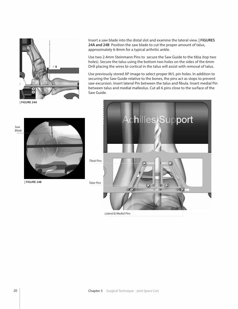
Insert a saw blade into the distal slot and examine the lateral view. | FIGURES 24A and 24B Position the saw blade to cut the proper amount of talus, approximately 6-8mm for a typical arthritic ankle.
Use two 2.4mm Steinmann Pins to secure the Saw Guide to the tibia (top two holes). Secure the talus using the bottom two holes on the sides of the 6mm Drill placing the wires bi-cortical in the talus will assist with removal of talus.
Use previously stored AP image to select proper M/L pin holes. In addition to securing the Saw Guide relative to the bones, the pins act as stops to prevent saw excursion. Insert lateral Pin between the talus and fibula. Insert medial Pin between talus and medial malleolus. Cut all 6 pins close to the surface of the Saw Guide.

Chapter 3 Surgical Technique - Joint Space Cuts 21
Install the Anti-Rotation Notch Insert (200290002 through 200290006) into the Resection Guide. | FIGURE 25 Using the appropriate sized Anti-Rotation Drill (200178002 through 200178006) drill the tibia for the anti-rotation notch. | FIGURE 26
Be sure to drill bi-cortical.
Anti-Rotation Notch Insert200290002 - 200290006
Anti-Rotation Notch Drill 200178002 - 200178006
CAUTION: Surgeon must withdraw the 6mm Drill to clear the location of the Anti-rotation Drill and saw cuts.
Select the appropriate sized Saw Blade (200138101S through 200138106S). Two Saw Blade widths are available. Although wider blades tend to provide more control and cutting accuracy, the narrow blade will be required for the smaller cuts with a size 2 & 3. Make resection through the tibia, talus and medial/lateral slots of the resection guide. | FIGURES 27A and 27B The Saw Blades must remain parallel to the Saw Guide during all cuts.
| FIGURE 26
| FIGURE 25
Saw Blades200138101S - 200138106S
Saw Blade(Saw not shown)
| FIGURE 27A - Tibia | FIGURE 27B - Talus

Chapter 3 Surgical Technique - Joint Space Cuts
Saw Cut Gauge
| FIGURE 28A | FIGURE 28B
22
With the Saw Cut Gauge, check that the bone has been cut all the way through. If the Saw has reached its maximum depth proceed to the next step. Remove the Anterior Fixture and Saw Guide without removing the Steinmann pins.
Keep the Steinmann pins in the tibia and talus. At the top of the tibial cut, use an osteotome to cut down towards the talus at 60° and remove the anterior section of the tibia. | FIGURES 28A and 28B
Illustrations shown without INBONE® footholder.

Chapter 3 Surgical Technique - Joint Space Cuts 23
Check that your talar resection is complete by using a 1/2 inch osteotome. Complete the cut if necessary and gently lever the resected dome out anteriorly. It can typically be removed in one piece by grabbing the Steinmann Pins.
To facilitate removal of the remaining posterior tibia, the Corner Chisel (IB200070) and a mallet can be used to finish off bone cuts in the proximal corners of the resected tibia. | FIGURES 29A and 29B The Corner Chisel is laser marked to indicate the anterior to posterior depth of the various size tibial trays.
CAUTION: Care must be taken to a that the Corner Chisel does not penetrate too deeply, as neurovascular injury may occur. Do not rely solely on the depth indications on the Chisel to determine resection depth. If unsure, utilize a lateral fluoroscopic image to confirm proper depth of the chisel.
Corner ChiselIB200070
| FIGURE 29B
Bone Removal Screw(Ratcheting Handle not shown)
| FIGURE 30
Bone Removal ScrewIB200051
Ratcheting Handle44180025
Using a pin driver, insert the Bone Removal Screw (IB200051) into the resected tibial bone. Attach the Ratcheting Handle (44180025) to the Bone Removal Screw to aid in removing the remaining tibial section through traction. | FIGURE 30
| FIGURE 29A
Illustrations shown without INBONE® footholder.
Illustrations shown without INBONE® footholder.

24 Chapter 3 Surgical Technique - Joint Space Cuts
Insert the 90° Posterior Capsule Release Tool (IB200050) into the joint space and use to free up the posterior capsule soft tissues attachments to the resected tibia. | FIGURES 31A and 31B
Bone Removal Screw
Posterior CapsuleRelease Tool
| FIGURE 31A | FIGURE 31B
Posterior Capsule Release ToolIB200050
If necessary, use the appropriate size drill bit to provide additional definition of anti-rotation notch. Take care not to widen the notch. A reciprocating saw or bone rasp may be used to remove excess bone, taking care to follow the previously made cut line. Remove loose bone pieces and irrigate the joint space. | FIGURE 32
| FIGURE 32
CAUTION: Failure to adequately clean the proximal corners of the tibial resection can lead to improper seating of the INBONE® Tibial tray.
Illustrations shown without INBONE® footholder.
Illustrations shown without INBONE® footholder.

Chapter 3 Surgical Technique - Ream the Tibia
Tibial Reamer Tip200046001 - 200046004
Tibial Stem Clip200381001 - 200381004
Tibial Reamer Drive Rods200089 or 200395 (T-Handle)
Select the Reamer Tip (200046001 through 200046004) diameter based on the size of the desired Tibial Stem. Use the same size reamer as the desired Tibial Top and Mid Stem implants. It is recommended to ream for a 2mm press fit on the Tibial Base Stem if possible. For instance, if the Tibial Stem Base is 16mm, the Reamer size will be 14mm. Using the Holding Clip (200381001 through 200381004), insert the Tibial Stem Reamer Tip. Manually thread the Reamer Driver to avoid cross threading. | FIGURES 33A and 33B
CAUTION: Do not use a Powered Drill to attach the Reamer Tip. There is a high risk of cross-threading the Reamer using a Power Driver.
Clip
Tibial ReamerTip
Ream the tibial IM canal to the depth of the tibial stem construct determined by the number of stem pieces previously templated (5-7cm). | FIGURES 34A and 34B Refer to Appendix B for tibial stem height details and recommended reaming depths. Note that the reamer Drive Rod is marked with a depth indicator that can be viewed through the anterior window.
| FIGURE 34A | FIGURE 34B
| FIGURE 33B| FIGURE 33A
Ream the Tibia
Withdraw the 6mm Drill and IMMEDIATELY replace with the Reamer Drive Rod with a Jacobs chuck attached.
25

Chapter 3 Surgical Technique - Ream the Tibia
Tibial Tray AP SizerIB282902 (left) - IB282906 (right)
Select the appropriate size Tibial Tray AP Sizer (IB272902 through IB282906) and insert into the resected joint space, using both ends of the sizing tool to determine the optimum AP size Tibial Tray (standard or long). The Strike Rod (200085) should be used to fully seat the Sizer into the tibial resection.
Utilize a lateral fluoroscopic image to evaluate the coverage (anterior and posterior) of the tibial cortex. | FIGURE 36 It is critical to obtain sagittal plane coverage of the tibia, particularly anteriorly where more load is distributed. Thus, in choosing the correct size, overhang of the prosthesis is permitted if the standard size does not rest upon the tibial cortex.
The Tibial Tray AP Sizer is also used to check the tibial cut surfaces and ensure that no bone fragments will impede proper positioning of the Tibial Tray. Remove excess bone as necessary and irrigate.
AP Standard - illustrating undersized coverage.
AP Long - illustrating optimal coverage.
Strike Rod200085
| FIGURE 36
Tibial StemWrench
| FIGURE 35
Pull the reamer back into the joint space.
CAUTION: Do not reverse the drill rotation while the Reamer Tip is still in the tibia, as it will become unthreaded and remain in the tibia.
Using the appropriate sized Tibial Stem Wrench (200380001 through 200380004) unthread the Reamer Tip from the Drive Rod and remove from the joint space. | FIGURE 35 Repeat the reaming steps for all sizes of reamers required/desired.
CAUTION: It is strongly recommended that the surgeon use irrigation to clean the joint space between reamer sizes.
Leave the Reamer Drive Rod in the foot with tip slightly distal to the surface of the talar resection.
Tibial Stem Wrench200380001 - 200380004
26

27Chapter 3 Surgical Technique - Install Tibia Stems
| FIGURE 37
| FIGURE 38
X-Drive200071
Install Tibia StemsIn most cases the Top Tibial Stem and first Mid Stem piece can be pre-assembled and then placed into the joint space. Using the X-Drive (200071) and the appropriate sized Tibial Stem Wrench firmly tighten these two components together on the back table. Orienting the Wrench in the distal direction as labeled, slide the Wrench onto the Mid Stem piece with a finger or thumb holding it in place. Introduce the components into the joint space placing the Top Stem piece into the intramedullary canal of the tibia. | FIGURE 37
Insert the X-Drive through the Cannula and up through the talus. | FIGURE 38
Illustrations shown without INBONE® footholder.
Illustrations shown without INBONE® footholder.
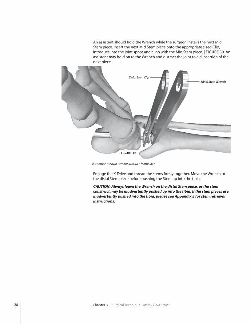
An assistant should hold the Wrench while the surgeon installs the next Mid Stem piece. Insert the next Mid Stem piece onto the appropriate sized Clip, introduce into the joint space and align with the Mid Stem piece. | FIGURE 39 An assistent may hold on to the Wrench and distract the joint to aid insertion of the next piece.
Tibial Stem Wrench
| FIGURE 39
Engage the X-Drive and thread the stems firmly together. Move the Wrench to the distal Stem piece before pushing the Stem up into the tibia.
CAUTION: Always leave the Wrench on the distal Stem piece, or the stem construct may be inadvertently pushed up into the tibia. If the stem pieces are inadvertently pushed into the tibia, please see Appendix E for stem retrieval instructions.
Tibial Stem Clip
Chapter 3 Surgical Technique - Install Tibia Stems
Illustrations shown without INBONE® footholder.
28

29Chapter 3 Surgical Technique - Install Tibia Stems
Note: Wrench orientation
Release Hole
Select the appropriate Base Stem piece and introduce with a Clip. Tightly thread the Base Stem using the X-Drive. Remove the Clip and insert a Wrench on the Base Stem. | FIGURE 40
With the Base Stem tight, remove the Wrench and rotate the stem construct so the Morse taper release hole is pointing anteriorly and is in line with the anti-rotation notch. The Base Stem release hole is used to detach the Tibial Base Stem from the Tibial Tray in the event of revision. Place the Wrench back on the Base Stem.
| FIGURE 40
Illustrations shown without INBONE® footholder.

Install Tibia TrayIrrigate the Morse Taper surface of the Base Stem to clean it.
CAUTION: Contamination on the Morse Taper surfaces can prevent proper seating.
Remove the X-Drive and replace with the Strike Rod. Hold the Tibial Stem Base with the Wrench and introduce the Tibial Tray using the Holding Tool (200364002 or 200364003). Insert the Morse Taper into the Stem Base. Push the Strike Rod into the small detent on the bottom surface of the Tibial Tray. | FIGURE 41
CAUTION: Remove the Holding Tool before striking the Strike Rod. Otherwise it can be locked in place.
Holding the Tibial Stem Base firmly, strike the end of the Strike Rod several times with a mallet to seat the Morse Taper.
CAUTION: The Tibial Tray will not seat if the wrench is in the wrong orientation. Wrench is marked “Distal” for correct orientation.
Remove the Wrench, rethread the Holding Tool to the Tibial Tray, and test the Morse Taper connection by trying to rotate the Tibial Tray against the Stem. If properly engaged, both the stem and Tibial Tray should move as one unit.
Holding ToolM4 - 200364003M3 - 200364002
Chapter 3 Surgical Technique - Install Tibia Tray
HoldingTool
WrenchStrikeRod
30
| FIGURE41

| FIGURE41
31Chapter 3 Surgical Technique - Install Tibia Tray
| FIGURE 42
If choosing to use bone cement, apply it to the top and sidewalls of the Tibial Tray component.
CAUTION: In the United States, the INBONE® Total Ankle is intended for cemented use only.
CAUTION: Be sure not to get any cement on the anterior face or bottom of the Tray.
Seat the assembly firmly into the tibia using a mallet and the Strike Rod. Remove the Strike Rod and visually check the anterior alignment. Check a lateral fluoroscopic image for proper posterior seating. | FIGURE 42
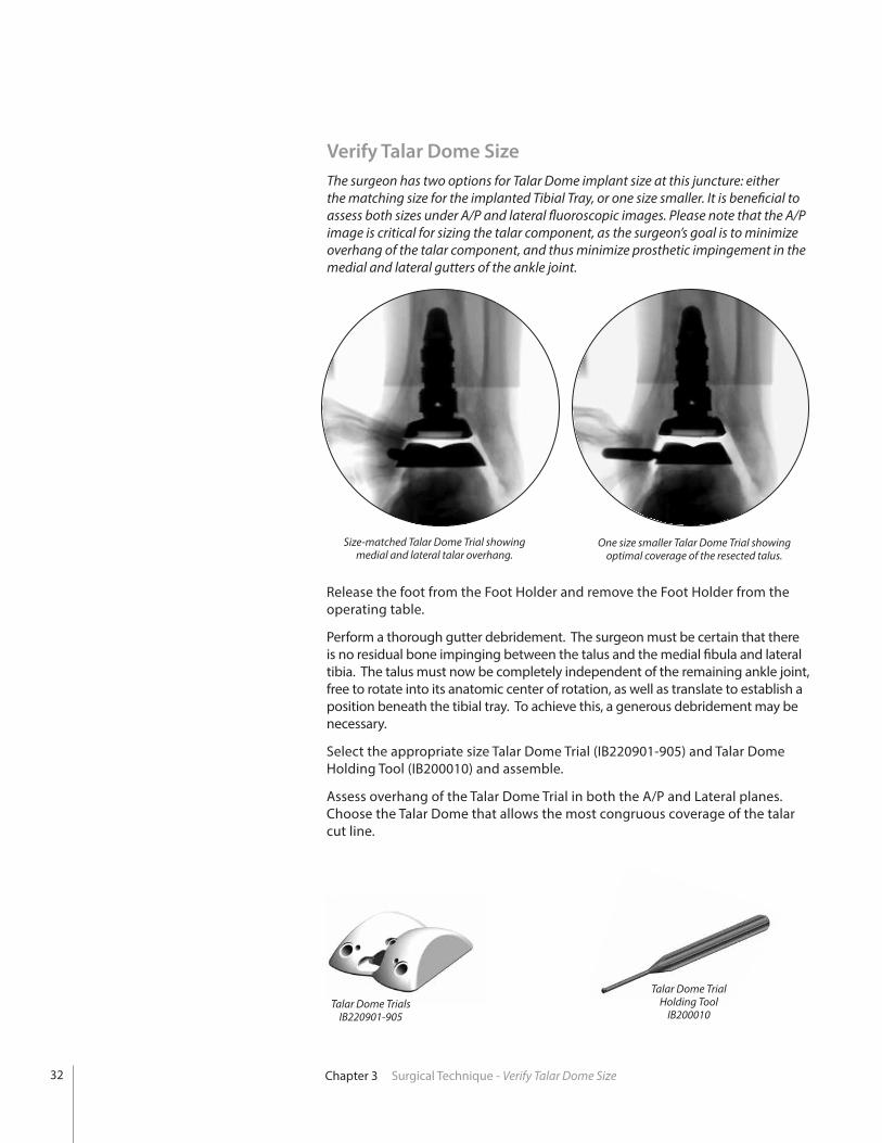
Verify Talar Dome SizeThe surgeon has two options for Talar Dome implant size at this juncture: either the matching size for the implanted Tibial Tray, or one size smaller. It is beneficial to assess both sizes under A/P and lateral fluoroscopic images. Please note that the A/P image is critical for sizing the talar component, as the surgeon’s goal is to minimize overhang of the talar component, and thus minimize prosthetic impingement in the medial and lateral gutters of the ankle joint.
Talar Dome Trial Holding Tool
IB200010Talar Dome Trials
IB220901-905
Size-matched Talar Dome Trial showing medial and lateral talar overhang.
One size smaller Talar Dome Trial showing optimal coverage of the resected talus.
Release the foot from the Foot Holder and remove the Foot Holder from the operating table.
Perform a thorough gutter debridement. The surgeon must be certain that there is no residual bone impinging between the talus and the medial fibula and lateral tibia. The talus must now be completely independent of the remaining ankle joint, free to rotate into its anatomic center of rotation, as well as translate to establish a position beneath the tibial tray. To achieve this, a generous debridement may be necessary.
Select the appropriate size Talar Dome Trial (IB220901-905) and Talar Dome Holding Tool (IB200010) and assemble.
Assess overhang of the Talar Dome Trial in both the A/P and Lateral planes. Choose the Talar Dome that allows the most congruous coverage of the talar cut line.
Chapter 3 Surgical Technique - Verify Talar Dome Size32

33Chapter 3 Surgical Technique - Trial Reduction
Poly Insert Trial
Poly Insert TrialHolding Tool
| FIGURE 44A
Training Note for Trial Holding Tools
There are two different trial holding tools in the instrument set: one for the Talar Dome Trials (silver handle) and one for the Poly Insert Trials (gold handle). In addition to having different colored handles, the two instruments also have slightly different designed tips.
Talar Dome Trial Holding Tool
Poly Insert Trial Holding Tool
Trial ReductionHolding Tool to Trial Attachment To attach the Holding Tool to the corresponding trial component, insert the tip of the tool into the keyed slot and turn 90° counter-clockwise to lock the connection. | FIGURES 43A and 43BTo remove the holding tool turn the handle 90° Clockwise and remove.
Using the Poly Insert Trial Holding Tool (IB200110) install the appropriate size Poly Insert Trial (IB202106-6520) into the Tibial Tray. The locking tab of the Poly Insert Trial should engage the Tibial Tray. | FIGURE 44A
Using the Talar Dome Trial Holding Tool introduce the appropriate size Talar Dome trial into the joint space. | FIGURE 44B
Talar Dome Trial
Talar Dome Trial Holding Tool
Talar Dome Trial Poly Insert Trial
CCW to lock CCW to lock
| FIGURE 43B| FIGURE 43A
| FIGURE 44BPoly Insert Trial Holding Tool
IB200110
Talar Dome Trial Detail
Poly Insert TrialsIB202106-6520
1.4mm TemporaryFixation Pin Holes
2.4mm Pin Holesfor Talar Stem
4mm Anterior Peg Drill HolesHolding Tool
Connection
X X

Polyethylene ThicknessWhile the final polyethylene thickness does not have to be definitively chosen during the trial phase, it is important to have what is perceived to be the appropriate size trial poly to accurately determine the placement of the talar component. The trial poly used for the reduction should fit appropriately to determine the center of rotation of the talar component; therefore, trialing multiple size polys may be necessary. Note that after insertion of the final talar dome, the height of the poly can be reassessed.In order to determine proper polyethylene height the following factors must be considered: • Smooth range of motion of the ankle without anterior or posterior
impingement. • Ligaments are tensioned both medially and laterally WITHOUT over-
tensioning. Over-tensioning is noted when the trial talar component tilts following trial poly insertion. Alternatively, with range of motion, the talar component becomes incongruent with the trial poly, which can identify too much tension on the ankle replacement. Over-tensioned joints may cause increased polyethylene wear, and should be avoided.
• Stress the ankle joint into varus and valgus. The trial components should not tilt.
• The trial poly should engage the sulcus in the talar dome trial without allowing medial/lateral translation.
Chapter 3 Surgical Technique - Trial Reduction34

35Chapter 3 Surgical Technique - Trial Reduction
1.4mm Pins
| FIGURE 46
Under lateral plane fluoroscopy ensure the posterior portion of the talar component is resting on the posterior portion of the patient’s residual talus (establish congruence). | FIGURE 45
While holding the talus in this position, use a marking pen to mark the anterior portion of the talar component with reference to the patient’s residual talus.
Be sure to observe the talar component with reference to the line on the residual talus previously drawn. This will ensure the talar component does not migrate anteriorly during the range of motion.
To accurately perform the range of motion, place some axial compression of the components to maintain position, and flex and extend the ankle. The surgeon will observe the talar component rotating into the anatomic position for this particular patient. Note that the surgeon must not only be cognizant of the talar position in the lateral plane, but must simultaneously maintain medial/lateral coverage as evidenced by the previous A/P plane fluoroscopic views.
Once Talar Dome Trial has settled into optimum anatomical position, install two 1.4mm Pins (500036) through the Talar Dome Trial to temporarily hold it in place. | FIGURE 46
Note that with the talar component pinned in position, the surgeon should once again place the ankle through a range of motion to ensure tibio-talar articular congruence. Also, confirm through lateral fluoroscopy that the prosthesis did not shift anteriorly.
| FIGURE 45
1.4mm Pin500036

2.4mm Pin
Using the 4mm Anterior Peg Drill (IB200020), drill a hole through the medial and lateral openings in the Talar Dome Trial. The drill has a hard stop designed to set the appropriate drilling depth in the talus for the Talar Dome anterior pegs. | FIGURE 47
Remove 1.4mm Pins and use the Talar Dome Trial Holding Tool to slide Talar Dome Trial off the remaining 2.4mm Pin. The foot may be plantarflexed to aid in removal of Talar Dome Trial.
Note: Do not ream the talar dome anterior pegs when implanting the saddle style dome. (Saddle design does not have this feature).
Install a 2.4mm Steinmann Pin through the center of the Talar Dome Trial to the depth of the selected Talar Stem sing a lateral view to verify depth. Be certain that the Talar Dome Trial is sitting flush with the cut line of the talus before placing this pin. | FIGURE 49
Anterior Peg Drill
Use the Poly Insert Trial Holding Tool to remove the Poly Insert Trial. Foot may be plantarflexed to aid in removal of Poly Insert Trial. | FIGURES 48A and 48B
CAUTION: The Poly Insert Trial has a small locking tab that engages the Tibial Tray. To remove Poly Insert Trial be sure to first pull down on the holding tool to disengage tab before pulling out.
| FIGURE 49
| FIGURE 47
| FIGURE 48B| FIGURE 48A
4mm Anterior Peg DrillIB200020
Chapter 3 Surgical Technique - Trial Reduction36

37Chapter 3 Surgical Technique - Ream for Talar Stem
Talar Stem Reamer
Ream for Talar StemInstall the appropriate length Talar Stem Reamer (10mm-200432010 or 14mm-200432014) over the pin and ream to the depth of the selected talar stem. | FIGURE 50 The reamer has a hard stop designed to set the appropriate reaming depth. | FIGURE 51 Optionally, use a lateral fluoroscopic view to verify depth.
CAUTION: The Talar Stem is not intended for subtalar fusion or subtalar joint impingement. Please carefully evaluate the anatomy of each patient before implantation.
Remove the Reamer and Steinmann Pin.
| FIGURE 50
| FIGURE 51
Talar Stem Reamers(10mm-200432010)(14mm-200432014)

Dome Strike Tool
Talar Dome
Strike Block
| FIGURE 54
Dome Strike(pre-assembled
with Dome Strike Tip)IB200030IB200031
ANTERIOR
POSTERIOR
ANTERIOR
POSTERIOR
Align the Dome Strike Tool (IB200030 and IB200031) on the Talar Dome and with a mallet, hit the top of the strike tool 2-3 times to fully seat the Talar Stem. | FIGURE 54
| FIGURE 53| FIGURE 52
Strike BlockIB200060
Chapter 3 Surgical Technique - Assemble Talar Stem
Assemble Talar StemInsert the appropriate sized Talar Stem into the bottom of the Talar Dome | FIGURE 52, aligning the oblong post and matching the oblong hole in the Talar Stem. Talar Stem and anterior pegs should be parallel.
Insert the Talar Stem and Talar Dome assembly into the Strike Block (IB200060). | FIGURE 53
38

39Chapter 3 Surgical Technique - Install Talar Dome
Install Talar DomePlace the foot in plantar flexion and insert the blue Tray Insert (200419002 through 200419006) into the Tibial Tray to protect the Talar Dome surface during installation. If choosing to use bone cement, apply it to the bottom surface of the Talar Dome. Using the M4 Holding Tool, insert the Talar Dome, aligning the Talar Stem and pegs with the prepared holes in the talus. | FIGURE 55 Once the Talar Dome is aligned, remove the Tray Insert.
Tray Insert200419002-200419006
| FIGURE 55
CAUTION: In the United States, the INBONE® Total Ankle is intended for cemented use only.
Align the Dome Strike Tool on the Talar Dome and with a mallet, hit the top of the strike tool to fully seat the Talar Dome. | FIGURE 56 Utilize a lateral fluoroscopic image to ensure that the Talar Dome is fully seated. If the Talar Dome is difficult to fully seat in hard bone, it may be advisable to remove the Talar Dome and increase the diameter of the anterior peg holes slightly with the 4mm drill.
| FIGURE 56

Install Poly InsertSelect the appropriate size Poly Insertion Tool (1000600102 through 100063106) and Plunger Block (200277002-006). Place a Nut Insert (200422) into the pocket of the Poly Insertion Tool. Position the Plunger Block at the back of the tool and retain with the appropriate Jack Screw (200289 or IB200040). | FIGURE 57 Jack Screw must match the Tibial Tray, e.g. size 3 Long Tibial Tray requires the use of the Long Jack Screw. Long Jack Screw is gold colored and standard Jack Screw is silver.
Select proper size Poly Insert and slide into the dovetail of the insertion tool.The anterior face of the Poly Insert (indentation) must face the Plunger.
Install the appropriate Attachment Screw (200329101 through 200329103) into the anti-rotation notch of the Tibial Tray. | FIGURE 58
Poly Insertion Tool
Poly Insert(note indention)
Jack Screw Plunger Block
Nut Insert
Attachment Screw
| FIGURE 58
Poly Insertion ToolLeft: 100063102-100063106
Right: 1000600102-1000600106
Nut Insert200422
Jack ScrewStandard: 200278
Long: IB200040
Attachment ScrewSize 1 & 2: 200329101Size 3 & 4: 200329102Size 5: 200329103
Plunger Block200277002-006
Attachment Nut200329201
| FIGURE 57
Chapter 3 Surgical Technique - Install Poly Insert40

41Chapter 3 Surgical Technique - Install Poly Insert
Attachment Nut
Jack Screw
Insertion Tool
Tibial Tray
Attachment Screw
| FIGURE 59
Apply Reaction Force to keep tool at 90°
Slide the Poly Insertion Tool assembly over the Attachment Screw and align flush with the anterior surface of the Tibial Tray. Thread the Attachment Nut onto the Attachment Screw to lock the Poly Insertion Tool to the Tibial Tray. | FIGURE 59
Turn the Jack Screw to advance the Poly Insert into the Tibial Tray.
CAUTION: To prevent incomplete seating of the poly insert, properly irrigate the tibial tray prior to poly insertion.
Apply slight “Reaction Force” as necessary to keep Insertion Tool at 90° to Tibia. | FIGURE 60
| FIGURE 60
90°

Poly Impact Tool200286
Poly Impact Tool
| FIGURE 61
Final Procedures
Check for proper articulation.
Close the wound.
Cast the foot in a slight dorsiflexion position.
Keep the foot non-weight bearing for 6 weeks.
| FIGURE 62A | FIGURE 62B
Select the Poly Impact Tool (200286). At a 60° angle give the Poly Impact Tool a final tap to fully seat the Poly Insert. Check that the Poly is fully seated.
Take final AP & Lateral fluoro images for record keeping. | FIGURES 62A and 62B
Continue turning the Jack Screw until it bottoms out, then remove the insertion tool. | FIGURE 61
Chapter 3 Surgical Technique - Install Poly Insert42

43Chapter 3 Surgical Technique - Morse Taper Release
Morse Taper ReleaseThread Morse Taper Release Pin (200356003) into Morse Taper Release Handle (200355).
Insert tip of the Morse Taper Release Pin into the Morse Taper Release Hole of the Implant.
Angled surface of the Release Pin should face distally.
Holding the implant firmly, strike the end of the Morse Taper Release Handle with a mallet until the Morse Taper becomes unseated. | FIGURE 63
Morse Taper Release Pin
Threaded hole for holding tool
Morse Taper Release hole
Talar Dome
Talar Stem
Morse Taper Release Pin Tibial Tray
Morse Taper Release Hole
Base Stem
Tibial TrayTalar Dome
Morse Taper Release hole
Talar Dome
Note pin orientation
(Assembled Tool)
Morse Taper Release Handle(200355)
Morse Taper Release Pin, 3mm(200356003)
CAUTION: Release pin must be inserted into the Talar Dome from anterior to posterior to disengage taper. Failure to do so could result in pin becoming permanently jammed.
| FIGURE 63

Explant Information
INSERT REPLACEMENT
To remove the Poly Insert, first install two large diameter threaded Steinmann Pins into the anterior face of the implant. With a pair of pliers pull distally on the Steinmann Pins in attempt to unlock the Insert from the Tibial Tray. A narrow osteotome may be inserted into the anterior region of the insert to facilitate removal. A hemostat may be used to remove the insert once it is no longer locked to the tibial base. Care must be taken not to scratch or mar any component that is not intended to be removed.
TIBIA AND TALAR COMPONENTS
To remove the components, small osteotomes, power saws, or other surgical instruments may be used to disrupt the bone-cement interface. Care must be exhibited to save remaining bone stock as well as to prevent fracture. Once the components have been removed, rongeurs or small osteotomes as well as other surgical instruments may be used to remove the remaining cement.
If the removal of the implant is required due to revision or failure of the device, the surgeon should contact the manufacturer using the contact information located on the back cover of this surgical technique to receive instructions for returning the explanted device to the manufacturer for investigation.
Postoperative Management
Postoperative care is the responsibility of the medical professional.
Chapter 3 Surgical Technique - Explant Information44

45Appendix A INBONE® II Instrumentation
INBONE® II INSTRUMENTATION A
ppen
dix
A
IBT2KIT1 INBONE® II Case 1, Tray 1
1. Right U-Bracket (100080)2. Left U-Bracket (1000081)3. Achilles Bracket (200412)
4. Achilles Support (IB100099)5. T-Handle Wrench, 5mm (200433)
4
5
3
1
2
1
IBT2KIT1 INBONE® II Case 1, Tray 2
1. Right Base (1000082)

Appendix A INBONE® II Instrumentation46
1. Left Base (100083)
1
2
3
4
5
IBT2KIT1 INBONE® II Case 1, Tray 3
Caddy
1. Lock Washer, M6 (200415)2. Washer, M6 (200413)3. Screws, M6 (200043014)
4. Hex Key, 5mm (200343)5. Thumb Screw, ¼-20 (200416)
1

1. Calf Tray (200304)2. Calf Bracket (IB100102)3. U-Bracket (100073)
4. ML Rods (IB100064)5. AP Rods (100057)6. Anterior Adjusting Rotating Plate (IB100033)
47Appendix A INBONE® II Instrumentation
1
2
3
4
5
IBT2KIT1 INBONE® II Case 2, Tray 1
IBT2KIT1 INBONE® II Case 2, Tray 2
1. Knob, M6 (100085) 2. Alignment Template (IB100093)
1
2
6

48 Appendix A INBONE® II Instrumentation
1. ANT Fixture Top Plate (IB100035)2. ANT Fixture SidePlate (IB100036)
3. Foot Plate, Right (100098)4. Foot Plate, Left (100097)
1
IBT2KIT1 INBONE® II Case 3, Tray 1
3
4
2
1. Foot Plate (100096)2. Heel Cup, Left (100088)
3. Heel Cup, Right (100089)4. Block, Forefoot (100101)
1
3
4
IBT2KIT1 INBONE® II Case 3, Tray 2
2

49Appendix A INBONE® II Instrumentation
1. AP Plate (100095)2. ML Plate (IB100094)3. Anterior Adjusting Plate (IB100032)
1
3
IBT2KIT1 INBONE® II Case 3, Tray 3
2

50 Appendix A INBONE® II Instrumentation
1. Steinmann Pin, 2.4mm (200072)2. K-Wire, 1.4mm x 228mm (500036)3. Drill, Anti-Rotation (200178002 through 200178006)4. Drill, 6mm (200134)5. Nut, Cannula (200402)6. Collet Primary Bushing (200385)
7. Primary Bushing (200401)8. Cannula, Foot, Bottom (200166)9. Trocar (200099)
1
IBT2KIT1 INBONE® II Case 4, Tray 1
3
4
2
1. Anti-Rotation Insert (200290002 through 200290006)2. Stem Strike (blue) (200421)3. Dome Strike, Saddle (blue) (IB200032)4. Dome Strike, Sulcus (yellow) (IB200031)5. Poly Insertion Tool (200422)
6. Extraction Tool, Base Stem (200428)7. Extraction Tool, Mid/Top Stem (200102)8. Nut, Attach Screw(200329201)9. Reamer, Tibia (200046001 through 200046004)
1
3
4
Caddy
2
5
78
6
9
5
7
8
6
9

51
7. Primary Bushing (200401)8. Cannula, Foot, Bottom (200166)9. Trocar (200099)
Appendix A INBONE® II Instrumentation
1. Drive, Tibia Reamer (200089)2. T-Handle, Reamer (200395)3. Wrench, Tibia Stem (200380001 through 200380004)4. Clip, Tibia Stem (200381001 through 200381004)5. Pin Puller (18770140)
6. Gauge, Saw Cut (200383)7. Posterior Capsule Release Tool (IB200050)8. Quick Connect Ratcheting Handle (44180025)9. Corner Chisel(IB200070)10. Saw Guide Fixture (200216002 through 200216006)
1
3
IBT2KIT1 INBONE® II Case 4, Tray 2
2
IBT2KIT1 INBONE® II Case 4, Tray 3
1. Tibial Tray AP Sizers – Right (IB282902 through IB282906)2. Morse Taper Release Handle (200355)3. Pin Cutter, 3.2mm (200427)
4. Pin, Morse Taper Release (200356003)5. Tibial Tray AP Sizers – Left (IB272902 through IB272906)
3
1
5
5
7
8
6
9
2
4
10
4

52 Appendix A INBONE® II Instrumentation
1. Rod, Angle Fixture (200404)2. Strike Rod (200085)3. X-Drive (200071)4. Holding, Tool, M3 (200364002)5. Holding, Tool, M4 (200364003)6. Calcaneal Drill, 9mm x 2.4mm (200424009)7. Calcaneal Drill, 10mm x 2.4mm (200424010)
8. Multi-Hole Angle Fixture (200349)9. Angle Fixture (200403)10. Angle Block (100104)11. Talar Reamer, 10mm (200432010)12. Talar Reamer, 14mm (200432014)13. Wrench, Orienting (200230)
1
3
IBT2KIT1 INBONE® II Case 5, Tray 1
2
5
7
8
6
9
4
10
11
12
13

53Appendix A INBONE® II Instrumentation
2. Talar Dome Trials (IB220901 through IB220906)3. Stem Strike (200344)4. Tray Insert (200419002 through 200419006)5. Seat Block (IB200060)6. Dome Strike Handle (IB200030)7. Talar Peg Drill, 4mm (IB200020)8. Poly Insert Trial Handle (IB200110)9. Talar Dome Trial Handle (IB200010)
1
3
IBT2KIT1 INBONE® II Case 5, Tray 2
2
5
7
8
6
9
4
1. Poly Insert Trials Size 1+ 6mm Poly Trial (IB202106)Size 1+ 8mm Poly Trial (IB202108)Size 2 6mm Poly Trial (IB202206)Size 2 8mm Poly Trial (IB202208)Size 2+ 8mm Poly Trial (IB203208)Size 2+ 10mm Poly Trial (IB203210)Size 3 8mm Poly Trial (IB203308)Size 3 10mm Poly Trial (IB203310)Size 3+ 10mm Poly Trial (IB204310)
Size 3+ 12mm Poly Trial (IB204312)Size 4 9mm Poly Trial (IB204409)Size 4 11mm Poly Trial (IB204411)Size 4+ 10mm Poly Trial (IB205410)Size 4+ 12mm Poly Trial (IB205412)Size 5 9mm Poly Trial (IB205509)Size 5 11mm Poly Trial (IB205511)Size 5+ 10mm Poly Trial (IB206510)Size 5+ 12mm Poly Trial (IB206512)

5454 Appendix A INBONE® II Instrumentation
1. Poly Insert Tool - Left (100063102 through 100063106)2. Jack Screw, Long (IB200040)3. Jack Screw (200278)4. Poly Impact Tool (200286)5. Plunger Insert Tool (200277002 through 200277004, 200277105 & 200277006)
6. Attachment Screw, M3 (200329101)7. Attachment Screw, Long, M3 (200329102)8. Attachment Screw, M4 (200329103)9. Poly Insert Tool - Right (100060102 through 100060106)
13
IBT2KIT1 INBONE® II Case 5, Tray 3
25
7
8
6
9
4

55Appendix A INBONE® II Instrumentation
1. Size 1+ 10mm Poly Trial (IB202110) Size 1+ 12mm Poly Trial (IB202112)2. Size 2 10mm Poly Trial (IB202210) Size 2 12mm Poly Trial (IB202212)3. Size 2+ 12mm Poly Trial (IB203212) Size 2+ 14mm Poly Trial (IB203214)4. Size 3 12mm Poly Trial (IB203312) Size 3 14mm Poly Trial (IB203314)5. Size 3+ 14mm Poly Trial (IB204314) Size 3+ 16mm Poly Trial (IB204316)6. Size 4 13mm Poly Trial (IB204413) Size 4 15mm Poly Trial (IB204415)7. Size 4+ 14mm Poly Trial (IB205414) Size 4+ 16mm Poly Trial (IB205416)8. Size 5 13mm Poly Trial (IB205513) Size 5 15mm Poly Trial (IB205515)9. Size 5+ 14mm Poly Trial (IB206514) Size 5+ 16mm Poly Trial (IB206516)
IBTA-KIT4 INBONE® II Poly Trial Instrument Kit
1 2
3 4
5 6
7 8
9

56 Appendix B Stem Specifications
App
endi
x B
StemSpecifications
Units = mm
IMPLANT OPTIONS
Ø12 Ø14 Ø16Top Stem(Diameter)
Mid Stem(Diameter)
Base Stem(Diameter)
Talar Stem(Diameter)
18
10 14
Ø16 Ø18
9.5
9.5 13.5
13.5
Ø12 Ø14 Ø16 Ø18
Exclusive FitSize #2, #3 - 16mm onlySize #4, #5, #6 - 18mm only
Stem Component Specifications
Tibial Stem Construct Specifications
Size 1 - 3 Size 4 - 6
No Ø18Mid Stems
1 x Ø18Mid Stems
2 x Ø18Mid Stems
46.5 50.5 54.5 58.5

57Appendix C Implant Specifications
App
endi
x C
ImplantSpecifications
Size A B C
2 26 32 7 2 Long 26 36 7 3 28 36 7.5 3 Long 28 39 7.5 4 31 39 8 4 Long 31 42 8 5 34 42 9 5 Long 34 46 9 6 37 46 10
INBONE® Tibial Component
Size A B C 1 30 32 10 2 33 34 10 3 36 36 10 4 39 39 11 5 42 42 12
INBONE® Sulcus Talar Component
C(mm)
A(mm)
B(mm)
B(mm)
A(mm)
C(mm)
Appendix D Ordering Information
App
endi
x D
OrderingInformation
58
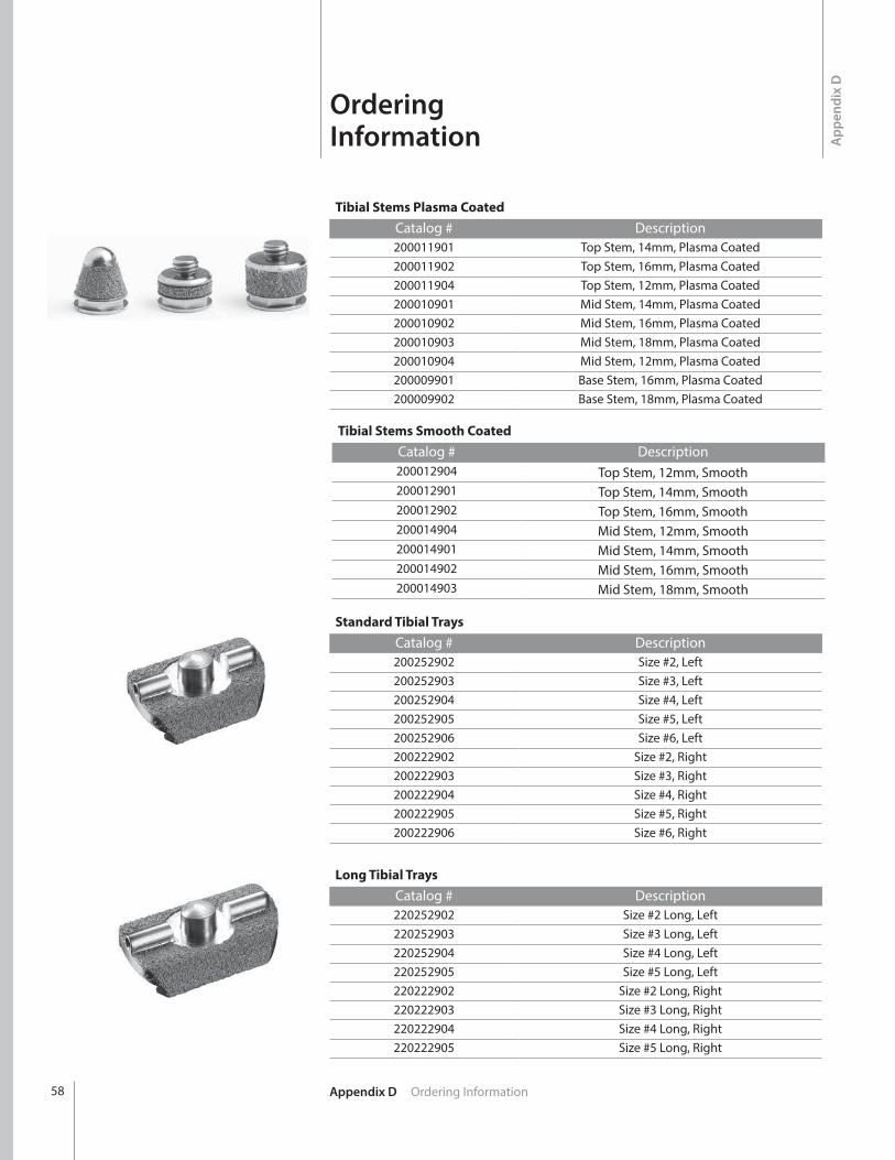
Tibial Stems Plasma CoatedCatalog # Description200011901 Top Stem, 14mm, Plasma Coated200011902 Top Stem, 16mm, Plasma Coated200011904 Top Stem, 12mm, Plasma Coated200010901 Mid Stem, 14mm, Plasma Coated200010902 Mid Stem, 16mm, Plasma Coated200010903 Mid Stem, 18mm, Plasma Coated200010904 Mid Stem, 12mm, Plasma Coated200009901 Base Stem, 16mm, Plasma Coated200009902 Base Stem, 18mm, Plasma Coated
Standard Tibial TraysCatalog # Description200252902 Size #2, Left200252903 Size #3, Left200252904 Size #4, Left200252905 Size #5, Left200252906 Size #6, Left200222902 Size #2, Right200222903 Size #3, Right200222904 Size #4, Right200222905 Size #5, Right200222906 Size #6, Right
Long Tibial TraysCatalog # Description220252902 Size #2 Long, Left220252903 Size #3 Long, Left220252904 Size #4 Long, Left220252905 Size #5 Long, Left220222902 Size #2 Long, Right220222903 Size #3 Long, Right220222904 Size #4 Long, Right220222905 Size #5 Long, Right
Tibial Stems Smooth CoatedCatalog # Description200012904 Top Stem, 12mm, Smooth200012901 Top Stem, 14mm, Smooth200012902 Top Stem, 16mm, Smooth200014904 Mid Stem, 12mm, Smooth200014901 Mid Stem, 14mm, Smooth200014902 Mid Stem, 16mm, Smooth200014903 Mid Stem, 18mm, Smooth

59Appendix D Ordering Information
Sulcus Talar DomeCatalog # Description220220901 Size #1, Right & Left220220902 Size #2, Right & Left220220903 Size #3, Right & Left220220904 Size #4, Right & Left220220905 Size #5, Right & Left
Talar StemCatalog # Description200347901 10mm Long200347902 14mm Long
Sulcus Poly Insert
Catalog # Description220222106E Size #1+, 6mm Thick, Right & Left220222108E Size #1+, 8mm Thick, Right & Left220222206E Size #2, 6mm Thick, Right & Left220222208E Size #2, 8mm Thick, Right & Left220222210E Size #2, 10mm Thick, Right & Left220222212E Size #2, 12mm Thick, Right & Left220223308E Size #3, 8mm Thick, Right & Left220223310E Size #3, 10mm Thick, Right & Left220223312E Size #3, 12mm Thick, Right & Left220223314E Size #3, 14mm Thick, Right & Left220224409E Size #4, 9mm Thick, Right & Left220224411E Size #4, 11mm Thick, Right & Left220224413E Size #4, 13mm Thick, Right & Left220224415E Size #4, 15mm Thick, Right & Left220225509E Size #5, 9mm Thick, Right & Left220225511E Size #5, 11mm Thick, Right & Left220225513E Size #5, 13mm Thick, Right & Left220225515E Size #5, 15mm Thick, Right & Left

Appendix D Ordering Information60
Sulcus Plus-Size Poly InsertCatalog # Description
220222110E Size 1+ Plus, 10mm Thick, Right & Left220222112E Size 1+ Plus, 12mm Thick, Right & Left220223208E Size #2 Plus, 8mm Thick, Right & Left220223210E Size #2 Plus, 10mm Thick, Right & Left220223212E Size #2 Plus, 12mm Thick, Right & Left220223214E Size #2 Plus, 14mm Thick, Right & Left220224310E Size #3 Plus, 10mm Thick, Right & Left220224312E Size #3 Plus, 12mm Thick, Right & Left220224314E Size #3 Plus, 14mm Thick, Right & Left220224316E Size #3 Plus, 16mm Thick, Right & Left220225410E Size #4 Plus, 10mm Thick, Right & Left220225412E Size #4 Plus, 12mm Thick, Right & Left220225414E Size #4 Plus, 14mm Thick, Right & Left220225416E Size #4 Plus, 16mm Thick, Right & Left220226510E Size #5 Plus, 10mm Thick, Right & Left220226512E Size #5 Plus, 12mm Thick, Right & Left220226514E Size #5 Plus, 14mm Thick, Right & Left220226516E Size #5 Plus, 16mm Thick, Right & Left
AccessoriesCatalog # Description200178002 Drill, Size 2 Anti-Rotation Notch200178003 Drill, Size 3 Anti-Rotation Notch200178004 Drill, Size 4 Anti-Rotation Notch200178005 Drill, Size 5 Anti-Rotation Notch200178006 Drill, Size 6 Anti-Rotation Notch
200134 Drill, 6mm200072 2.4mm Steinmann Pin500036 1.4mm K-Wire
IB200051 Bone Removal Screw200138101S Saw Blade Stryker Narrow200138102S Saw Blade Stryker Wide200138103S Saw Blade Hall/Linvatec Narrow200138104S Saw Blade Hall/Linvatec Wide200138105S Saw Blade Stryker System 6 Narrow200138106S Saw Blade Stryker System 6 Wide200138107S Saw Blade Stryker System 7 Narrow200138108S Saw Blade Stryker System 8 Wide

61Appendix D Ordering Information
Large Revision PolysCatalog # Description
220222114E INBONE® Poly SZ 1+ 14mm Sulcus Total Ankle220222116E INBONE® Poly SZ 1+ 16mm Sulcus Total Ankle220222214E INBONE® Poly SZ 2 14mm Sulcus Total Ankle220222216E INBONE® Poly SZ 2 16mm Sulcus Total Ankle220223216E INBONE® Poly SZ 2+ 16mm Sulcus Total Ankle220223218E INBONE® Poly SZ 2+ 18mm Sulcus Total Ankle220223316E INBONE® Poly SZ 3 16mm Sulcus Total Ankle220223318E INBONE® Poly SZ 3 18mm Sulcus Total Ankle220224318E INBONE® Poly SZ 3+ 18mm Sulcus Total Ankle220224320E INBONE® Poly SZ 3+ 20mm Sulcus Total Ankle220224417E INBONE® Poly SZ 4 17mm Sulcus Total Ankle220224419E INBONE® Poly SZ 4 19mm Sulcus Total Ankle220225418E INBONE® Poly SZ 4+ 18mm Sulcus Total Ankle220225420E INBONE® Poly SZ 4+ 20mm Sulcus Total Ankle220225517E INBONE® Poly SZ 5 17mm Sulcus Total Ankle220225519E INBONE® Poly SZ 5 19mm Sulcus Total Ankle220226518E INBONE® Poly SZ 5+ 18mm Sulcus Total Ankle220226520E INBONE® Poly SZ 5+ 20mm Sulcus Total Ankle

Appendix E Stem Retrieval62
App
endi
x E
Stem Retrieval
Retrieving a Base Stem Piece from the Tibia Insert the T-handle Reamer through the bottom of the foot and thread the Base Stem Extraction Tool in the open joint space. | FIGURE 64 A size 14 Clip is used to introduce the Base Stem Extraction Tool. Once it is threaded onto the Reamer replace the Clip with a size 14 Wrench to tighten. | FIGURE 65
Remove the Wrench and push the Extraction Tool up in the tibia until contact is made with the Base Stem Piece. Continue to turn the T-handle clockwise to engage the threads of the Base Stem Piece. | FIGURE 66 Once threads are engaged, pull out the stem construct until the base stem is visible in the joint space. | FIGURE 67
Select these tools:
Tibial Stem Clip #14200381001 - 200381004
Tibial Stem Wrench #14200380001 - 200380004
Tibial T-Handle Reamer Drive Rod
200395
Base Stem Extraction Tool200428
| FIGURE 64 | FIGURE 65
| FIGURE 66 | FIGURE 67
Place the appropriate size Wrench on the Base Stem and turn the T-handle counter-clockwise to disengage the Extraction Tool from the Base Stem. Leaving the Wrench on the Base Stem push the stem construct back into the tibia. | FIGURE 68 Use the size 14 Wrench to remove the Extraction Tool from the T-Handle Reamer. | FIGURE 69
| FIGURE 68 | FIGURE 69

63Appendix E Stem Retrieval
Mid/Top Stem Extraction Tool200102
Retrieving a Mid or Top Stem Piece from the Tibia Follow the exact steps detailed on previous page for removing the Base Stem piece, substituting the Mid/Top Stem Extraction Tool (#200102) for the Base Stem Extraction Tool (#200428).

™Trademarks and ®Registered marks of Wright Medical Technology, Inc. ©2015 Wright Medical Technology, Inc.All Rights Reserved.
011941B_18-Aug-2015
Wright Medical Technology, Inc.1023 Cherry RoadMemphis, TN 38117800 238 7117901 867 9971www.wmt.com
Wright Medical EMEAAtlas Arena, Australia BuildingHoogoorddreef 71101 BA Amsterdamthe Netherlands011 31 20 565 9060
Wright Medical UK Ltd.Unit 1, Campus FiveLetchworth Garden CityHertfordshire SG6 2JF United Kingdom011 44 (0)845 833 4435