1. - boondocker€¦ · remove the muffler and egt. remove the stock ... and install the power...
TRANSCRIPT


Revised 10/23/2015 Page 2 of 10
www.boondockers.com………………..... ……….………………....877-522-7805
1.Remove the gauge, side panels, hood and headlight.
Remove the air box from the throttle bodies then
remove the seat and gas tank.
2.Carefully remove temp sensor from air box using
a small pick or screw driver. DO NOT THROW
AWAY; this will be used for later use in the install.
3.Remove the muffler and EGT. Remove the stock
rubber muffler isolators from the bottom of the
muffler. DO NOT THROW AWAY; these will be
used later in the install.
4.Remove hood from headlight assembly and flip
upside down. Break off the weld dots on the air box
assembly. Pull apart the air box assembly. Discard
the lower air box & white air box tube.
5.Cut the upper air box matching both sides on
the cut (as seen in picture).
6.Cut the upper hood/air box assembly as seen in
picture for clearance purposes. Cut remaining
weld dots off of the upper air box.

Revised 10/23/2015 Page 3 of 10
www.boondockers.com………………..... ……….………………....877-522-7805
7.Remove the throttle bodies & reed cages from
the machine.
8.Remove the stock reed pedals and replace
them with new turbo reeds. DO NOT mix them
up. Reinstall back in engine and install the
throttle bodies.
9.Install the power adapter cable into the open
fuse holder. Install supplied fuse.
10. Hook up the ground right below the fuse
holder on the foot rest with the stock bolt.
Tighten the bolt so wires are pointed to the top
of the chain case.
11. Remove fuse holders from stock location
and install the power harness on the end of the
power adapter cable. Make sure red wire goes to
red wire.
12. Hook up throttle position harness to throttle
body. Zip tie all wires so they don’t chaff or
break off.

Revised 10/23/2015 Page 4 of 10
www.boondockers.com………………..... ……….………………....877-522-7805
13. Route wiring down the stock harness to the
power adapter harness and throttle position hook
ups. Use zip ties accordingly.
14. Install the throttle body tab clamp on the
throttle body with the tightening screw at the top
of the assembly. Install the silicone hose and
twist clamp into position then tighten clamp.
15. Install silicone on the left side of the
aluminum Y. Tighten the hose clamp. Leave all
the other clamps loose for proper alignment and
fitting.
16. Install the rest of the air box. Make sure you
index the hose clamps so you can access them
for tightening after you install the gas tank.
Leave the hose clamps loose.
17. Install the injectors in the injector rails. Use
assembly lube so you don’t tear an o-ring.
18. Route the fuel line as shown in picture.
Don’t over tighten these bolts. Zip tie fuel lines
so they don’t kink then zip tie the wire harnesses
securely.

Revised 10/23/2015 Page 5 of 10
www.boondockers.com………………..... ……….………………....877-522-7805
19. Cut and splice into the return fuel line.
Install brass T into fuel line and tighten clamps.
Position for clearance, zip tie and secure as
shown.
20. Install the gas tank and tank support
member. The Y will touch gas tank slightly on
PTO side. There should be reasonable clearance
elsewhere.
21. Remove the clear line on rave valve solenoid
& Install check valve. Turn the blow off to down
position. Route and zip tie.
22. Remove pipe and apply silicone to exhaust
doughnut. Triple up springs on pipe and
reinstall.
23. Install intercooler using hose clamps on
cross bar. Install fan and route adapter harness.
24. Install the 3” charge tube. Do not tighten
hose clamps. Try to slide the charge tube closer
to the Y end for proper fit. Hook up the air temp
sensor to the control box. Zip tie into place.

Revised 10/23/2015 Page 6 of 10
www.boondockers.com………………..... ……….………………....877-522-7805
25. Install clutch cover then turn the Y on the
PTO side upwards until the clutch cover fits
properly.
26. Install stock temp sensor and zip tie. Hook
up the boost reference line to the push to connect
on the intercooler. Route so it does not chaff or
break.
27. CAREFULLY trim oil tank as shown using
sharp knife or cutters. DO NOT puncture oil
tank during this process.
28. Install heat tape on the chain case, hoses,
stock EGT cable, and oil tank. Newer models do
not require heat tape on chain case.
29. Drill the hole for the spring tab with a 3/16”
drill bit. This hole already exists so you only
will drill the plastic in the bell pan on the right
side.
30. Install the stock muffler rubber bumpers on
the turbo bracket using a flat blade screw driver.

Revised 10/23/2015 Page 7 of 10
www.boondockers.com………………..... ……….………………....877-522-7805
31.Install the turbo assembly then install the
spring supplied for turbo bracket tab to bulk
head spring tab.
32.Route the inside coolant line under the bulk
head bracket. Route up to the back side of
coolant bottle.
33.Remove the small coolant line from the back
of the coolant bottle. Then route to the coolant
hose you just removed. Make sure you secure
hose.
34.Route the outside turbo coolant hose under
the bulk head cross member to coolant bottle.
On standard turbo kits clean the belly pan, apply
heat to velcro, then install oil pump as shown.
35.Route & hook up power for oil pump to
power harness. Route coolant hose to coolant
bottle. Zip tie the hose & power harness away
from any hazard. Tighten coolant hose clamps.
36.Install the waste gate solenoid. Use the
Velcro supplied to mount the solenoid. Use heat
to activate the glue on the Velcro.

Revised 10/23/2015 Page 8 of 10
www.boondockers.com………………..... ……….………………....877-522-7805
37.TIAL ONLY. Install the waste gate on the
inlet. Plug the remaining holes in the Tial waste
gate. You will not use the coolant fitting option
on this waste gate.
38. Using an air saw, cut exhaust side plastic for
exhaust to fit through. This hole will be
approximately a 3 1/2” hole. If desired, install
heat tape to the lower inside side panel.
39. Test fit the head light assembly to the
intercooler mount bracket. Tighten all the hose
clamps into position making sure the head light
assembly and charge tubes fit correctly.
40. Check for clearance on the clutch cover and
the 3” charge tube. Tighten all air box and
charge tube hose clamps.
41.Install Tial muffler. When installing the
muffler rotate the top of muffler to the inside of
the snow machine for a equal clearance to both
the side panel, chain case and stock oil tank.
42. Install the factory EGT sensor into the turbo
muffler, then remove the stock heat tape and
insulation from the side panel then install the
heat tape as shown.

Revised 10/23/2015 Page 9 of 10
www.boondockers.com………………..... ……….………………....877-522-7805
43. Cut the shroud just enough to run control
box wiring and boost reference line through,
then zip tie wires as needed.
44. Turn handle bars all the way to the left and
install the cold air intake as shown in picture.
45. Install the hose from boost solenoid to the
intercooler.
46. Install the hose from ECM onto cold air
intake box. Install the hose clamp on the cold air
bracket. Test fit the head light then tighten the
hose clamp.
47. Install the silicone hose on the cold air intake
box tube. Install the hose clamps between the
cold air intake tube and turbo.
48. Install the head light assembly. Route the
control box as shown in picture. Clean the
console then install Velcro. Heat the glue on the
Velcro to activate.
Revised 10/23/2015 Page 10 of 10
www.boondockers.com………………..... ……….………………....877-522-7805
49. Remove primary clutch. Remove the old
ramps. Install roll pins in ramps, index roll pins
as seen in picture. Be sure to perform clutch
adjustments to Ski-Doo specifications.
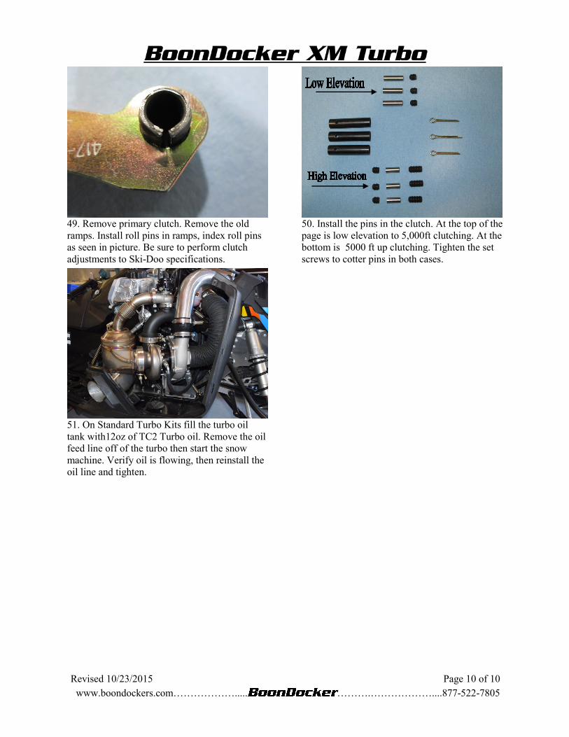
50. Install the pins in the clutch. At the top of the
page is low elevation to 5,000ft clutching. At the
bottom is 5000 ft up clutching. Tighten the set
screws to cotter pins in both cases.
51. On Standard Turbo Kits fill the turbo oil
tank with12oz of TC2 Turbo oil. Remove the oil
feed line off of the turbo then start the snow
machine. Verify oil is flowing, then reinstall the
oil line and tighten.