1 system-level power optimization. 2 contents low power system implementation techniques circuit...
TRANSCRIPT

1
System-level Power Optimization

2
Contents
Low Power System Implementation Techniques Circuit level
Clock gating MTCMOS Multiple voltage supply
Architecture level Memory Optimization Bus Optimization
Dynamic Power Management in System Level Introduction to DPM Structure of DPM Component-level DPM scheme DPM Policy Dynamic Voltage Scaling

3
Circuit Level Low Power System Implementation Techniques
Clock gating Most popular method for power reduction of clock
signals Need circuit to generate enable signal
Increases complexity of control logic Timing critical to avoid clock glitches at AND gate output
Additional gate delay on clock signal -> clock skew

4
Circuit Level Low Power System Implementation Techniques
Power gating ; Disconnecting the power source Applicable for each voltage island Long transient due to large capacitance An generate noise due to large inductive component Needs good power switch

5
MTCMOS ; a kind of power gating? Low VTH devices in logic to maintain performance when
active. High VTH current switch (header or footer) to cutoff
leakage path when sleep. Scheduling algorithm which controls sleep signal is
important.
Logic
VDD
sleep
Virtual GND
Virtual VDD
header
footersleep
Input Output
Circuit-Level Low-Power System Implementation Techniques

6
Multiple Supply Voltages Slows down non-critical path with lower voltage
supply Two or more power grids Need high-efficiency voltage converters for dynamic
voltage scaling ; Down conversion is cheaper than up-conversion. Dynamic power scheduling algorithm is important.
*
+
-
+
+
Low voltage supplyCritical path: need high speed logic
High voltage supply
In
Circuit-Level Low-Power System Implementation Techniques

7
Architecture-Level Low-Power System Implementation Techniques
Memory Optimization Code density minimization
Goal Minimize program memory occupation to reduce the
bandwidth of processor-memory communication Approaches
Employ custom instruction sets Object code compression

8
Memory Optimization
Custom instruction set Shorter size instruction sets than regular instruction
sets Example : ARM Thumb code (16-bit instruction)
Need a specific architecture for 16-it instruction support
32bit
Inst 1
32bit
Inst 2Inst 3Inst 4Inst 5
Inst 1Inst 2Inst 3Inst 4Inst 5
In this case,3/5 bandwidth reduction

9
Memory Optimization
Object code compression The size is the same for all instructions , but some or all
instructions are encoded and saved in instruction memory.
Available solution for embedded processors Same architecture can be used for different subset of
instructions Exploit the small subset of instructions used by firmware
code
Approaches Full code compression Selective code compression

10
Memory Optimization Full code compression
Replace all instructions with binary patterns of minimum width, [log2 N], where N is the number of instructions in the inst. set
Advantage Memory bandwidth for instruction is decreased. Advantageous when k > log2 N
Disadvantage Size of IDT may be very large because N is not small. log2 N may not be a multiple of 8.
IDT : Instruction Decompression Table
k bitsk bits
Core
k
MemoryMemory
log2N bits bits
CoreMemoryMemory
kIDT
log2N
Addr. Addr.
Inst. Inst.

11
Memory Optimization
Selective Code Compression Most program traces are covered by a small subset of
instructions. Compression of only such subset – instructions that
maximize program coverage Program is a mix of compressed and uncompressed
instructions.
8 bits
CoreMemoryMemory
k
IDT8
Addr.
Inst.
k
Buffer
Controller
12
Memory Optimization
Advantage Size of IDT is fixed and limited. Instruction fetching/decompression logic has reduced
complexity. Disadvantage
Requires a controller to handle instruction fetching

13
Memory Optimization
Data density optimization Same principle as code density optimization For the purpose of reducing memory traffic
dynamic size of the data-set More complex than code compression, because both
compression and decompression are required Hardware compression/decompression unit needed
Design trade-off between speed and power

14
Bus power optimization A large amount of power is dissipated in data
communication over heavily-loaded on-chip or off-chip busses.
Reduce switching activity on busses via signal encoding for power saving
Approaches Bus-invert coding Gray code addressing
PBus = n x C x Vdd2 x freq x activity , for an n-bit bus
Architecture Level Low Power System Implementation Techniques

15
Bus Optimization
Bus-invert coding Add redundant line INV to bus
When INV = 0 Data is equal to remaining bus lines
When INV = 1 Data is complement of remaining bus lines
At each cycle decide whether sending the true or compliment signal leads to fewer toggles
Sourcedata Received
data
Data bus
INV signalPolarity
Decision logic

16
Bus Optimization
Gray code addressing Most instruction addresses are consecutive
Use Gray code to address Word-oriented machines
Increments by 4 (32 bit) or by 8 (64bit) Modify Gray code to switch 1 bit per increment Gray code adder needed for jump
Dec Gray(i=1) Gray(i=4) Gray(i=8)012345678
000000010011001001100111010101001100
000000010011001001000101011101101100
000000010011001001100111010101001000 i : incrementi : increment
17
Introduction to DPM
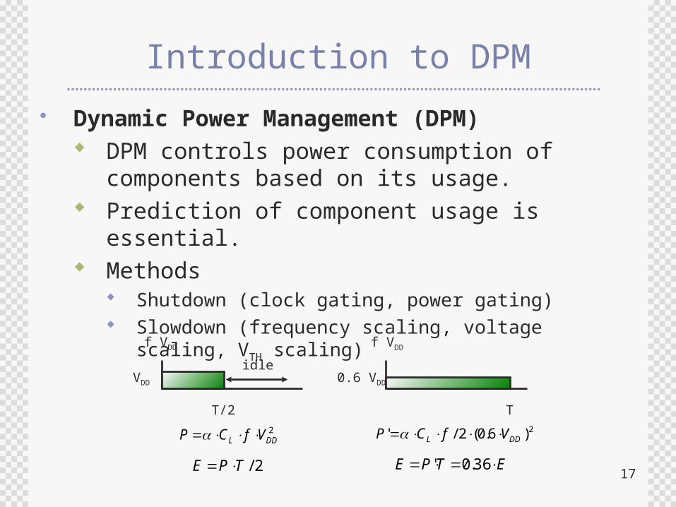
Dynamic Power Management (DPM) DPM controls power consumption of
components based on its usage. Prediction of component usage is essential. Methods
Shutdown (clock gating, power gating) Slowdown (frequency scaling, voltage scaling, VTH
scaling)
2DDL VfCP
f VDD f VDD
T/2 T
idle
2/TPE
2)6.0(2/' DDL VfCP
ETPE 36.0'
0.6 VDDVDD

18
Structure of DPM
Levels of embodiments of DPM Component level
Circuit, Block Power mode
System level Policy
The procedure which controls the power level of each module in a system
Circuit…
Block 1
Policy
Circuit Circuit…
Block n
Circuit…
System
power mode
power mode
request
request

19
Component Level DPM Scheme
Circuit level Clock off by clock gating Power off by footer/header of MTCMOS Multiple voltage supply
Block level Power off by shutdown of power supply to IPs When power off pattern of two block are similar,
shutdown together.
IP #2
IP #1
GND source
Virtual VDD Virtual GNDVDD source

20
Component Level DPM Scheme
Power mode Each state has
combination of enabled DPM technique. ex) The case that system
uses clock gating and block shutdown
Transitions between modes of operation have a cost.
Run
10μs
10μs 90μs
160ms
90μs
P=50mW P=0.16mW
P=400mW
Wait for interrupt Wait for wake-up event
Power state machine for the StrongARM processor
Idle Sleep
Power mode
Clock gatingBlock
shutdown
Run disabled disabled
Idle enabled disabled
Sleep enabled enabled
SA-100 Microprocessor Technical Reference Manual, Intel, 1998

21
DPM Policy
Predictive technique Uses a regression equation based on previous “On” and
“Off” times of the component to estimate the next “turn on” time.
Limitation It cannot handle components with more than two power
modes.Running
(R)Sleep
(S)Wake-up
Go-to-sleep
Predictive power management scheme
R RI
R E S RW
delay
R RI
R E W R
delay
R RI
R E S RW
delay
R RI
R E S RW I
Pre-wakeup scheme
I: Idle state E: Entering state W: Waking up state
M. Srivastava et al, “Predictive system shutdown and other architectural techniques for energy efficient programmable computation”,
IEEE TVLSI, Vol. 4, No.1 ,1996
C.H. Hwang et al, “A predictive system shutdown method for energy saving of event-driven computation”,
Proc. Int. Conf. on Computer Aided Design, pages 28-32, Nov. 1997

22
DPM Policy
Markov process Markov process is a process which uses a previous
state and pre-characterized probability to choose next state.
Power management optimization has been studied within the framework of Markov process.
When system is modeled as Markov chains It can model the uncertainty in system power
consumption and response times. It can model complex systems with many power states,
buffers, queues. It can compute power management policies that are
globally optimum.
G.A. Paleologo et al, “Policy optimization for dynamic power management”, Proc. DAC, 1998

23
DPM Policy
Power Manager
Service RequestorService Providerqueue
Request
ObservationObservation
Command
Structure of stochastic DPM
FSM of each module

24
Dynamic Voltage Scaling
DVS Reducing VDD is a single most effective way to reduce
power consumption. Reducing VDD is limited by the worst-case condition. Performance requirement varies with time. Solution
Slowdown : perform the job with just-in-time performance

25
DVS Applied Processor
Transition overhead Max 70μs for 5~80MHz transition Max 4μJ for 5~80MHz transition
ARMCore
16KBCache
SystemCo-processor
Bus
inte
rface
WriteBuffer
VC
O
CPU
Regulator
Fdesired VDD
System BUS 64KBSRAM ...
0.5MB
I/OChip
VBat T.D. Burd et al, “A dynamic voltage scaled microprocessor system”, IEEE JSSC, Nov. 2000

26
DPM using DVS on SoC
Divide SoC into 4 power domains Persistent 3.3V : I/O drivers and receivers Persistent 1.0V : PLL Persistent 1.8V : RTC, sleep management DVS : 1.0V ~ 1.8V (10mV/μs)
K.J. Nowka et al, “A 32-bit PowerPC System-on-a-Chip with support for dynamic voltage scaling and dynamic frequency scaling”, IEEE JSSC, Nov. 2002