1 ; .z : p . ,.i.ii, ii;;,;;-..si c,ojl 1 national ... · eaca tit no, 33% this investigation,...
TRANSCRIPT

.-
i
3 1176 01348 3962
. . ,\ .-. 1 ; .z : p . ,.i.Ii, ii;;,;;-..si c,oJL 1
u i:;-iL:
NATIONAL ADYISORY COMMITTEE .=-- FOR AERONAUTICS
TECHNICAL NOTE
,
No. 938
THE IBWARD BULGE TYPE BUCXLING OF ~:O~OCO~UE CYLIMDERS
.I - SALCULATSON OF TEE EFFECT UPON THE BU'CKLIJG
STRESS Oi? A COXPRESSIVE FORCE, A XZ~LIBEAR
DIRECT STRESS DISTRIBUTION, AXD A SREAS FORGE
By I-7. J.-Hoff and Bertram Klein Polytechnic Institute of Brooklyn
c
https://ntrs.nasa.gov/search.jsp?R=19930085214 2019-03-21T18:59:14+00:00Z
RESTRICTED ,
c.. , 4’
EATIOEAB ADVISORY CO1t'rITTEE FOR AERONAUTICS
TECHNICAL NOICE NO. 938 r
TEE INWARD BULGE TYPE BUC#tI~G OF 1~01X@GQUE CYEIXDEES
1 :- CbLC'iLkTIUN OF TEE EFFECT UPOE TtEE bUC?CLING
STRESS OF A COHPRESSIVE FORCE, A N.ONfiIWEAR
DIJGGT 8TBESS DISTRIBUTIOX, AND A SREAR FORGE'
By M. J. Hoff and Bertram Klein
. r
In the pr8Sent‘pbtrt f of a series Of 28gOrtS OP the inward bulge type buckling of mOnVCOgU8 oylinders the buckling load in combined betnding and compress$on Ss first derived. Mext the reduution in the buckling load beoause of a nonlinear direct stress distrfbution is de- termined. In experiments nonlinearity may result from an inadequate stiffness of the end attachments, Sn actual airplanes from the existenoe of concentrated loads or mlt-w.ltB. The effect of a shearing force upon the Crit- ioal load is $nvestigated through an analysis Of the re- sults of tests carried out at GALCIT with 56 r8inforoed * monocoque oylinder's, Finally a simple criterion of gen- eral instability fs presented in the form of a buckling inequalfty which should be helpful to the desfgner of a
. monocoque in determining the sizes of the rings required for excluding the possibiltty of inward bulge type buck- ling.
Xiarge monocoque fuselages rslnforced by &osely spaced stringers and rings are 15kely to buckle, when loaded, aoaording.to a Pattern whfoh inpolves simultane-
. ous distost%ons of the strtngers, the rings, and the sheet ooverlng. Thfs type of buckling is known as gen-
1 eral instability. Th8 details of the Pattern vary wOth 9 RESTRICTED

the loading. When the maximum stress in the fuselage is caused mainly by a bending moment, which may be accompa- nied by a small shear force, compressive force, or torque,
the characteristic feature of the distorted shape is an inward bulgs extending symmetrically from the stringer that is most highly stressed fn oompressI.ont (See fig. ' 1.) In some cases there is a single inward bulge; in others several appear along the most highly stressed COm-
pressive stringer, and these may oocur when the beading mT.pment is constant over a uniform portion of considerable length of a monocoque aylinder. Often a few shallower secondary bulges appear alongside the main bulges, but fn all the cases so far observed the distortions are re- stricted to the neighborhood of the stringbr most highly stressed in compressim. This type of general instability is denoted as inward bulge type buckling.
Calculations 0'9 the critical load corresponding to x the inward bulge type buckling were first published by
Hoff in 1938 in reference 1, in which a single experiment was also described. The derivation of the crItica load was aooomplished with the aid of the Bayleigh-Bitz- Tinoshenko method, and the strain energy stored in the sheet covering was neglected. $he first extensive sertes of t'ests was carri-ed out at OJ%LC~T and was reported in raference 2. Comparison of the test results with the theory of reference I showed great discrepancies, and the use of a semS-empirical formuxa was suggested. fn refer-. ence 3 Hoff revised his theory in the light of thSs new experimental evidence. The following are the baste fheas' of the revised theoryt
The strafn energy stored in the sheet couering is
negligibly small, and the shape's of the deflections of the rings and the stringers are governed by the least work requirement regardless of the strain energy stored in the sheet. The size of the bulge fn the circumferen- tial direction, however, is governed by the state of the sheet. The bulge extends only to regions where the shear rigidity of the panels is reduced because of the buok- ling of the sheet between the rings and th-e stringers, 'Phe circumferential length of the bulge is characterfzed by the parameter n which is the ratLo of v to the an&e rp0 measured (in radians) from the stringer which is most highly stressed fn uonpressfon to the stringer where the deformation of the ring ends, As a rule, n is greater than 2, since the bulge is not likely to ex- tend to the tons%on side of the aonocoque cylinder,
NACA TX No, 938 3
There is no theory available, however, by which the actual. value of n could be determined. In reference 3 it was suggested that a dhart developed from.the data of the GALCIT experiments be used for this purpose.
The object of the present investigations is to in- prove upon the theory of references 1 and 3. It is be- lieved that the crucial point in the development of a rigorous and reliable theory is an understanding of the action of the sheet covering. As a contribution toward this understanding the effect of a comprassive load upon the critical stress of general snstability in a beret mo- nocoque cylinder is calculated in the third section of this report., In the formula developed, the parameter n . appears. It is hoped that an experimental inveskigation, to be reported in part II of the present series dealing with the inward bulge type bucklang, will throw sono . light upon the variation of n with the o'ompressive load, Sinoe n depends masnly on the state of the sheet cover- ing, and this state is materially influenced by the corn- pressive force, knowledge of the functional connection be- tween n and the compressive force may'be helpful %n clarifying the 'role of the sheet in general instability.
The fifth section of this report presents a detailed analysis, in t4e light of the theory of r'eference 3, Of the experimental results obtained at GALCIT with 55 rein- forced monocoque cylinders tested in combined bending and shear and described in reference 4. The main purpose Of the analysis 3s to investigate the effect of a shear force upon the value of the parameter n. Simultaneously a con- venient semigraphi,l: method-of analyzing data of thks kind is developed .and presented.
The fourth and sixth sections present incidental re- sults of the investigations, The theory developed in the former became necessary because it was observed that an accurate linear direct stress distribution in a bent mo- nocoque cyltnder is not easily obtained in experiment. Consequently the effect of a deviation from linearity had to-be calculated. In the sfxth seotion an inequality is developed which permits a quick approximate determination as to whether a monocoque cylinder is liable to fail in general instability.
The,seventh and eighth seations compare theory with experiment. The ninth section contains the oonclusions.

*’
EACA TiT No, 33%
This investigation, conducted st the Polyteohnfc Institute of Brooklyn, was sponsored by, and conducted
. with financial assistanoa from, the National Advisory Gem- mittee for Aeronautics.
l
A crQss-sectional area Of a stringer
d stringer spaafng measured along the circumferenc%
% Youagfa modulus for the material of the ring
%tr Young*s madulus for the material of the stringer
h height of center of gravity of s%rfinger cross section measured perpsndioularlg from its base
1 cu sh moment of inertia of the ourved sheet taken about its centrofdal -is
Ir moment of inertia of ring seotion and its effec- tive width of abeet for 'bending in the radial
‘direction
I !: 0 moment of inertfs of ring seotion wtthout its sf- fectfve sheet for bending in the radial diree- ti0n
I str I St& r + t5/%l(l/na) Igtr t
I str 0 moment of inertia of stringer cross section with- out its effective sheet for bending in the radial direction
btr r moment of ineric3.a of stringer cross section and fts effectfve width of sheet for bending in the radial directton
1
Istr t moment of inertia of stringer tposs seotlon weth its‘effective sheet for bending in the tan- gential direction
I xx I str 0 . -e ?

NAOA TN No,. 938
Ly moment of inertia of stringer cross seotfon 0 yithout its effective sheet for bending fn the tangential dfrectioa
k, proportionality factor in the expression for the buckling of a cirtular cylinder loaded with uniform axial compression
pPVportiona3ity feactor in the 0Xpr8S8%On for the buokling of a flat rectangular plate loaded with uniform axial uoapression
If total length of wave in the axial direction
dfstanoe between the rings measured axially along the cylinder
m ziua"oar of rings included iti the length II
WI ,192, Iia,& functions of the parameter n associated with the determination of the strain eaergfes EtOre$ in the rings and the stringers, and the external work
n a parameter charactsrfzing the shape of the Ping defleotfon whiuh 2s equal, to the ratio of the total circumference to that cut off by the buakldng pattern, or TT/~P,
P CT load casrled by the most highly compressed stringer and its effective wddth of sheet at buckling in pure bending
'cr gi P Br when pattern Is general. instabilftg
Per p P or when pattiern is panel %nstability
P,, tot load carried by the most highly compressed stringer and its effective vridth of sheet at buckling in bsndfng and compression
r the radius of the circular oglinder
R a function of n similar to those denate& by i41 l iJa , and so forth
s total number of strdngers in the struoture
t the thiqkness of the sh8et aovering

a* waca IN x0. 938 16
%
U str
2wcu
wr
Wt
w
x '
.
2a
Y
AL
Aye
E
%&X
6
A
A
. no.
-
u
the strain energy stored in the rings
the strain energy stored in the stringers
effecttve width of curved sheet
radial displacement of a point on a ring or a stringer
tangential dfsplacement of a point on a ring or a stringer
work done by external load
coordinate measuring distance along the axis of the cylinder
the distance between thu centroidal axes cf the. stringer cross section alone and of the combined stringer cross section and its effective curved sheet
maximum deflectfon of the most compressed stringer of the nest hSghLy deflected ring
factor in the formula for the critical strain for pure bending
chaage in the distance between x = 0 and x = II due to distortions
shift in the center of gravity of the effective sheet due to its curvature
strain at the edge of a panel
strain in the most compressed stringer at failure
'an angular measure
equivalent length factor defined by equation (40)
buckzing index defined by equation (89)
reduced buckling index where effective width of sheet and tangential moment of inertia of stringer cross section are neglected
conpressive loab divided 3y perimeter

c . PACA Tti lo, 938 7
<. ii factor &similar to Y
tp an angular measure
VP, angle defining end of the siraumferential wave
If upon a reinforced monocoque oylinder a compres- sive lQad is aoting which is not sufficient tQ aause bucrklfng -by itself, and a aLowly increasing purs ber;ding moment is applied, failure may occur in the form of the inward bulge type general instability, !Ihe'calculation of the oorresponding critical load can be carried out in exactly the same manner as aas done in references 1 and 3 for the aase of pure bending alone. The buckled ehape Ls assumed to safisfy‘ the equations
provided that
where
n = -lcP,
and
wr radial displacement
V"'t tangeptial displaaement
a an indetermined parameter .
X coordinate measured along,the axis of the cylinder
L full wave length $n axiaj direct&on
(3)
(4)
NACA TN No, 938 , . . '8
v coordinate in the circumferential directisn
‘PO half wave length (in radians) in the circumferential. direction
E?::ations (1) and (2) are identical with equations (62) end (63) of reference 1. The deflected shape is shown in figures 1 to 3 whioh correspond to figures 13 to 15 of reference 1, and to figures 3 to 5 of reference 3.
The critical value of the bending moment is reached when tke work done by the direct stress, linearly dis- tributed over the cross sections at x = 0 and x = L, is equal to the-strain energy stored dn the rings and the longitudinals. The strain energy is caused by the defleo- tiona wr and wt: while the work is the product of the afore-mentioned direct stresses by the relative displace- ments of their podnts of appldcation corresponding to the assumed pattern Of distortions. Tn this buck?.Lng condi- tion the strain energy terms de not change beL*e,use of the added uniform compressOon. They are quoted hare from refsrenos 1 with some cthanges in t&e notation. The strain energy Ur stored in the rings is
u, s (37~/16) a8 K& + l)(l/r)"l,I, (51
where
14, = 173x3 - 1On + (2/n> (61
and m is the number of rings that distort at buckling, r the radius of the cylinders, and E,f, the bending rigfd'ity of a ring and the effective vidth of sheet at- tached to it. Equa+ion (5) corresponds to equation (65) of reference j., equation (6) to equation (8Oa). in refer- enct3 1, and in a substitution use was mahe of the first of equations (11) in reference 3. Equation (5) is valid only if P fs an integer.greater than unity; The strain energy Ustr stored in the Stringers iS
u str = 2naGI13 (r/d)~l/b3)EstrIstr . ('71
. where
NACA TN No. 938 9 L .
t . I str =I str r + (5/N (l/n21~str f (9)
and
a distanoe between adjao0nt stringers measured along the ciroumference .
B str Young's modulus for the materfal of the stringer
I str r and 'str t moments of inertia of the stringer
section for bending radially and tangentially, . respectively, both calculated with due oon- sideration of the effective width Of sheet
lquationa (71, (81, (goal,
and (9) correspond to equations (70), and (7Oa) of reference 1.
In the development of the expression for the work V done by the applied loads the proaedure of seotion 18(c) of reference 1 oan be followed. If u denotes the unl- formly distributed compressive load applied to a unit length of the perimeter of the cylinder, the total load
P
i;
acting upon an infinitesimal length rdcp of the eiraum- ference because of the simultaneous applioation of Qom- pressive force and bending moment oan be written, with oonsideration of equation (71) of reference 1, as
dP rp (P/d) 00s~ rdcp + v racp (10)
The shortening of the distance between points x = 8 and x- L lying on the same stringer ie
The total work done by the loads is, therefore4
n/n . w' =
F r AL [(P/d)coracp + u] dcp
l n/n

. .
* .
NACB TN No. 938
Where
L . .lO
- tL/(1-9nE)j + [1/2(1-16lia)~ I >
a, = fl/2na) s$n(nfn) {(S/4) - [l/Cl-n")J
(13)
Equation (3.2) differs from the sum of equatSans (76) and (78) of reference 1 only in the term containing U, while equations (13) and (14) are identical with equations (76a) an'd (782) of reference 1 (except for a printing e.rror Sn the latter).
As stated before,the %uckling condition fa
w= ur + w6tr
The load P ia the most highly stressed stringer bn the coqression side caused by ben'ding alone will be denoted by I-P,, if it satiefies equation (15). By writing Per for P in equation (121, by substituting the expressions of equation6 (55, (7), and (123 into equation (15), and by solving for Fcr, there i‘s obtained
is the nondimensional buckling index originally deftne,d in equation (86).of reference 1, IIoreover, Ll is the distance between adjacent rings, and consequently

Et'ACA ICW No.' 938
.
L= (m * 1) L,
Also,
M4 = (l/n) + (5/8)(lln') (19)
ghe number m of rings involved in buckling is d8- ternined from the requirement that P,, must ba a mini- mu.n . CJonsequently the BPffereatiaL ooefficient of f,, with respect to m must vanish. Equation (16) may be represented by the equation
Differentiating with respect to (m 9 l)= rather than to m, and equating the dffferential coefficient to zero re- sults in
I (II1 + 1j4 = (b/Et)
6ubst~tutiOn into equation (a) yields
w
Wfth the actual expressions instead of the symbols a, b, A, and 8, there is obtained
Tt was shown in,referenoe 3 {see equations (17) and (18)) that in very good, approxfmatfon
(21)
:fith the aid of equation f21) it can %e'shOwn that in

.
12
After seveial transformations and with the aid.of *@a-
,
i
Qan be written in the
0.9 - 1+-- ( J n2 vd .(23) This equation differs from equation (20) 0f referende 3 only in the t‘ern containfng u, It must be remembered, however, that in it P,., denotea the compressive force aaused by bending alone in the most highly stressed stringer bri the compression side. If the total load 'cr tot caused by bending and compression is requfred, Ud must be etdded tO the value of POP Gonseque.ntly,
P strIatr%Ir CT tot = n = a '-
e 0,9vd (244 r na
Since the value of n usually is equal to Or greater than 3, it may be seen from equation (24) that the total load Pn the most highly stressed stsfger ‘in compression is little changed if part of %t 5s causlbd by an external compressive load and part by 'an external bending moment, instead of being caused entirely by an external bending monient as in references 1 and 3. !&is statement is cor- rect only if the value of n OS not affected by the oom- pressive load, Bowever, if the compressive load de- creases the shearing rigidity of the sheet, it is ex- pected that n, and consequently Pgr tot* sh0uld de- crease, as was pointed out in reference 3. Consequently an experimental investigati0n of the inward 'bulge type general Instability in simultaneous bending and aonpres- sion should contribute ta the olariffcation of the effect of the sheet on the buokling load. Such an tnvestigation is now bgfng carried out Qa the kircraft Structures Itab- oratory of the Polyteohni0. Institute, of Brooklyn.' Its results will form the 00ntents of part II of this report.
NACA TN No. 938 13 * .
T3E EFFECT OF A NOBLINIAR DIRECT STRESS DISTRIBUTION I .
The effect upon general instability of a nonlinear .- . stress distribution over the cross section of the bent monocoque cylinder is investigated in this section, The investigation was undertaken because of the observation
-that an accurate linear stress distribution is not easily obtained in experiment. It is desirable, therefore, to Gstablish, at least approximately, the possible devia- tions from the theoretiaal buckling load caused by non- linearity. Xoreover, it is likely that concentrated loads, cut-outs, and so forth may result in a nonlinear stress distribution in.an actual airplane the effect of which mrght be a change in the load at which general in- stability would occur,
The probable maximum deviation can be easfly deter- mined on the assumption that the compressive stress is constant over the region of the inward bulge (tcpl <-co,). In the calculation of the buckling load the strain energy terms remafn unaltered, (5) to (9).
and are represented by equations The work done by the external load can be
recalculated upon replacing equation (10) by the equation
di? = (P/d)rdrp f Urd (25)
The effect of this :change is to have
'rr[(l/n) + (5/8)(1/n")] = 5rH4
in place of (X1 + R,) in equation 12. Consequently the critical load acting upon the stringers on the compression side may be Obtained by multiplying the right-hand side of equation (23) by
.
Since according to equation (22) the preceding ratio is equal to
. the critical load becomes
.

NACA TN No. 938 14
P 12s
cr = - ud (26) l+t0.9/sa)
Consequently the total buckling load - due to both bend: ing and compression - is given by the equation
P cr tot = + E J strlstrErlr
r2 (27)
Ic the case of pure bendin (Y = 0) equation (26) natu- rally reduces to equation $ 27). It may be seen that the deviation in the value of the critical Soad P,r from that corresponding to a linear stress distribution is sma1.l. In most oases 31 tor Cl+ (0.9/n")]
not being less than 3 the fac- is n.ot greater than 1.1, On the
other hand, the change in the stress distribution may cause n to become smaller, in which case the-decrease in the value of pcr would be more pronounced.,
Although from the preceding oaloylations ft follows that a deviation from a linear s.tress distribution slightly decreases the maximum load in the most highly uompressed stringer - that is, it decreases slightly the maximum compressive strain at buckling - at the same time the critical bending moment may even increase, With a linear stress distribution the bending moment is
o* * A'
J
;?.a %, = Z(P,r/d)r' cros2cp dcp = rrra(Pcr/d> (28)
0
If the rather unreasonable assumption is made that the compressive stress is constant over one-half the cross section of the cylinder, and an equal oonstant ten- sile stress prevaiis over the other half, the bending mO- ment becomes
% %r = 4(P,./d)ra
s coscp &p = 4r2(Por/d) (29)
0
Tharsfare, the quotient of the moments, for the same Per,

3
NACA TPN No. 938 15 .
ie 4/lT = 1.27, while the quotient of the oritiaal loads corresponding to constant and linear stress distribution, respectively, is 1.1. Hence the bending moment at buck- ling is increased in the ratio 1.16/l. With an assump-. tion which restricts the constant stress to a smaller region, the increment in the value of the critical bend- ing moment would be even smaller. Of course, stress dis- tributions encountered in practice are always closer to linearity than the law assumed in the present calcula- tions. Consequently it is reasonable to conclude that amall deviations from linearity slightly reduce the buck- ling stress, but hardly change the buckling moment.
ANALYSIS OF THD RDSULTS OF THE COKRIHED RpRDIRG AETD SHDAR
TPISTS CARRIED OUT IB THS GUGGERHIII~E ADROXAUTIC LABORATORY
OF THE CALtIF0R9Sfd igSTITUTE OF TZCXMOLOGY
The Combined Rending aad Shear Tests of GADCIT
Fifty-five reinforced monocoque cylinders were tested in combined bending and shear in the Guggenheim Aeronautic Laboratory of the California Institute of Technology. The results of the tests were published in reference 4, which also contains a report on eight additional cylinders of varying length tested in pure bending. In the present re- port all these test results are analyzed according to the theory developed in references 1 and 3. The main purpose of the analysis is to investigate the 'effect of shear upon the value of n, a parameter amply discussed in refer- ences 1 and 3 as well as in the preceding sections of this report. Simultaneouely a convenient semigraphip method of analyzing data of this kind is developed and presented, and the effeot of simplifying assumptions is investigated,
Figure 4 shows the monocoque cylinder and its details, together with part of the notation used in this report. The stringera are of alliptio oross section. Their cross- sectional area A is 0.0324 square inch. The greatest moment of inertia I YY = 0.000563 incha, the smallest mo- ment of inertia IHX= 0.000374 inch4. The cross section of the rings is rectangular, 0,366 by 0.0796 inch. xos t of the cylinders are of 16-inoh radius, the others of lo- inch radius, All are covered with sheet of O,OlO-inch

BACA TN Xo. 938 16
thickness. The materfal is heat-treated aluminum alloy, presumably l?S-T. The ring spacing varies from 1 inch to 8 inches, the number of stringers from 10 to 40.
Effective Width of Sheet
In the calculation of the effective width 2wcurved of a curved panel loaded uniformly in compression abnerI suggestion is followed here a5 in reference 3, Substitu- tion of equations (24b) to (24d) Anto equation (24a) of reference 3 gives:
&curved = (l/e)(d/r) 0.3t f J.535 E(t/d)(sr-- 0.3t)rVa32hj (30)
This is true a-5 long as .
2w Cd curved - (3Oal
In this equation E .5tands for the strain in the stringer at the edge of the panel. Since in th8 present analysis the effective width is calculated only in the most highly stressed region on the compression side, Emax will be substituted for E. in all numarical calculations.
Equation (30) is approximate since the value Of the numeric& coefficients vary, in general, with the geomet- ric and mechanical properties of the monocoque. Thus the factor O,3 in the formula for the critical strain Of the oircular cylinder, equation (24d) of reference 3, may better be approximated by Donnellts formula (see 880~ 22 of reference I), Moreover, the value 3,62 as5umed in the formula for the critical strain of a f$at plate may devi- ate considerably from reality if the panels are short (the ring spacing L, is small) and if the stringers and rings Provide much end restraint. In the genera> oase equation (30) may be written in the form:
In this equation k, represents the numerical coeffi- cient in the formula for the critdcal strain of the cir- cular cylinder:
.

- .
* .
+
.
E curved = k,(t/r) (32)
and k, the numerical coefficient in the formula.for the critical strain of the flat rectangular panel:
"flat = k&/d? (33)
Figure 5a is a plot of 2wcurved against E, czl ou- lated from equation (30) for the case t = 0.01 inch and r= 10 inches. The figure contains a family Of curves representing the effective width for cylinders having dif- ferent numbers 8 of stringers. ITFigure 5b differs from figure 5a only in that the radius of the cylinder r=16 inches. The curves show that the effeotive width de- oreases monotonically with increasing strain, which fs in agreement with expectation.
Homents of Inertia of Stringer and Effective
Curved Sheet Combinations
(a} In the radial direction.- Since the effective sheet acting with the stringer is curved, its center of gravity lies a distance Ay, above the point of inter- section 0 of the median line of the curved sheet with the y axis. (See fig. 6.) This distance is given by the expression;
s
(w/r > by, = I! - (1/2wt.')r't cos 8 d 9 (a)
-(w/r >
where 8 is measured counterclockwise from the axis y-y, as shown in the figure. If terms of higher order are neglected, evaluation of equation (a) yields the close approximation for the shift in the center of gravity of the sheet due to fts curvature:
AY, = C2w)a/(24r> (b)
The location of the center of gravity of the combina- tion Of strSnger and curved effective sheet.now can be

* .
. .
BACA TX No. 938 18 ,
determined. TakiZlg moments' about x-x, the horizontal axis through the center of gravity of the stringer alone, results in:
Here h is the distance from the x axis of the point of intersection of the bottom of the stringer with the y axis, and A is the cross-sectional area of the stringer.
The iJOment of inertia I,, sh of the curved sheet about its own oentroLda1 axis is:
I cu sh 5 r3t s (w/r) (l- - cos 6jade
- (w/r > - (2yt) (Aycla
= (4/s > (2w.t) (a~,)~ hi)
.
BY the use of the parallel axis theorem the moment of inertia. Istr r of the combination about the centroi- da1 axis through the common centroid can be calculated:
I str r=Ixx + FA + (4/5)(Ayc)a(2wt) '
+ b + (t/2) - Aye - sJ"(zwt) (8)
In this equation rxx is $he moment of inertia of the stringer cross section about ite oentroidal axis, Mith the aid of eq-uations (b) and (c) equation (8) can be re- duced to the form:
. I str r = xx I +
$a+ (t/2)- [(2w)2/(24r)]/
(1/2wt) + (l/A) d
(34)
Equation (34) is plotted in figure 7 for both cases r = 10 inches and r P 16 inches, The -formula gives cor- roct values for a flat sheet also if r is considered as

. . IJACA TN Bo. 938 19
increasing beyond all bounds. A curve for this case is drawn for comparison. It. shows that for large effective width neglecting the curvature may lead to definite de- viations from equation (34).
(b) In the tangential direction.- The combined moment of inertia of effective curved sheet and stringer for bending about the verttcal axis can also be calculated by simple integration-. From figure 6:
f
(w/r) '
(r sin 6) a
l -(w/r> rtd 6 f Iyy
where 'Ivy Ss the moment of inertia of the stringer sec- tion aboht the vertical axis. yields -the formula:
Evaluation of the integral
Istr t = Iyy + (1/2)tr3[C2w/r) - s'in(;?w/r)] (35)
c
For practical purposes it is permissible to expand the sine function in the bracket and to neglect all terms be- yond the second, Thus equation (35) reduces to:
I str t = Iyy -t (1/12)(2wj3t (36)
It 1s understood that it is arbitrary to calculate the tangential moment of inertia, assuming the same effective width as that used in determining the radial moment of inertia. Although this procedure 1ead.s to unreasonably high values for Istr t when 2wcurved is large, it is followed throughout thfs report, since no better approxi- mation is known at present.
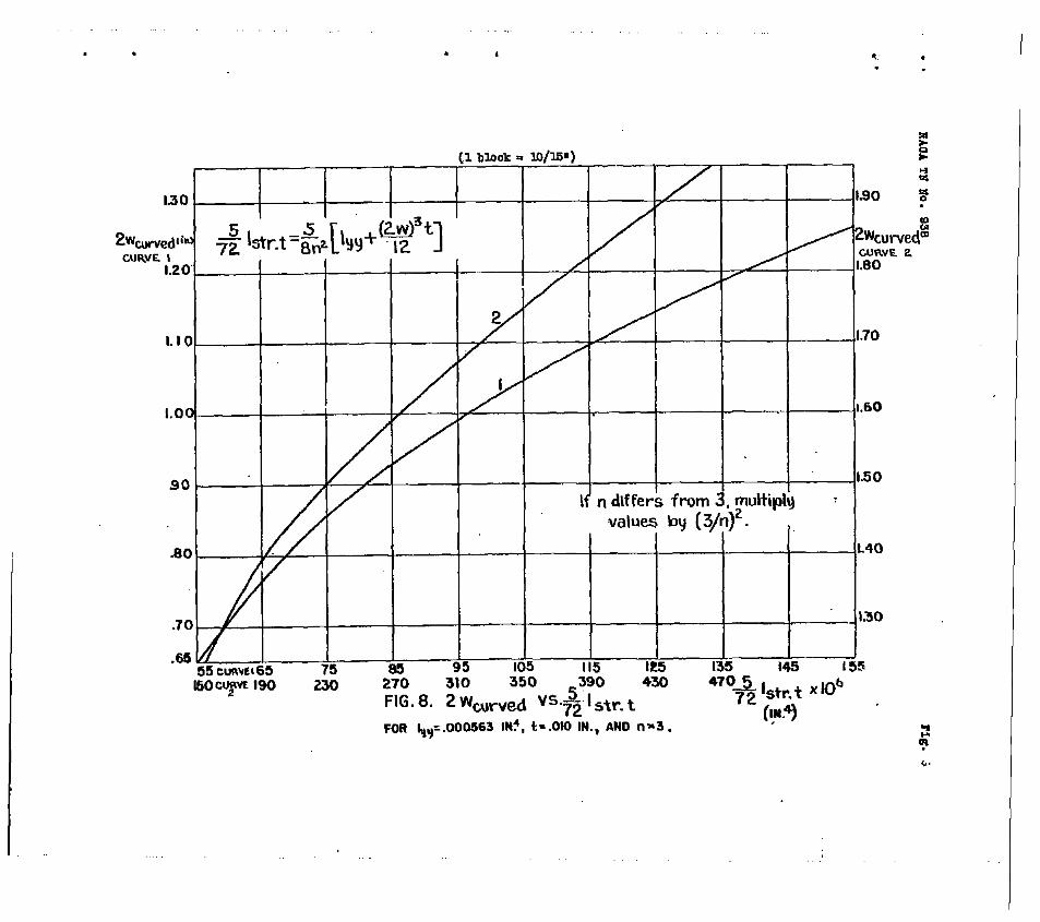
(c) Calculation of Istr.- In the analysis Istr t
always appears multiplied by (6/8)(l/n2). This value is plotted in figure 8 for n = 3. If n is different, the correct value can be obtained by multiplying by the fac- tor (3/n)2.
Equation (9) can now be graphed, plotting 2wcurved against Istr for both radii r = 10 inches and r = 16 inches taking n = 3. (See fig, 9,)

HACA TN'Eo. 938
Effective Width of Sheet Acting with the Rings
20
In all calculations the effective width of sheet acting with the rings is assumed to be equal to 0.366 inch, the width of the ring. This arbitrary assumption is made since it does not appear likely that much of the curved sheet would follow the deflection pattern of the ring; If it flattens and bends about its own ceatroidal axis, much less strain energy is stored in it than if it bends axout the common centroid of the ring and sheet combination. The actual deflection pattern, of course, corresponds to the least possible strain energy.
.-. The One-Quarter Power Law
St was shown in reference 3 that the buckling index A (given in equation (17) of this report) is connected by a quarter-power law with the equivalent length factor A, which is implicitly defined by the ea-uation
P cr = n2E str1st$/(XLl)2
The quarter-power law is
(37)
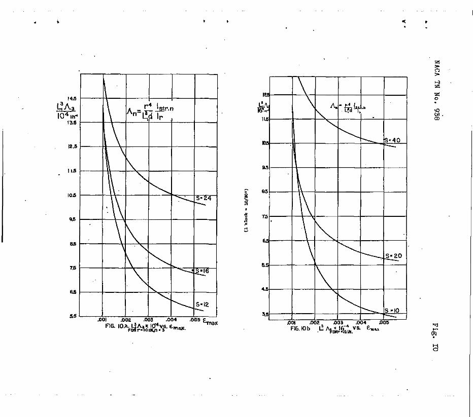
In the computations Young's modulus was taken equal . for all the materials of the cylinder. The simplified form of equation (17) is:
where the subscript n signifies that fstr, and con- sequently A, d.&pends upon the choice of the parameter n. Equation 39 is graphed in figures 10s and lob for r = 10 inches and 16 inches, respectively, and for differ- ent numbers of stringers.
Transformation of equatton (37) gives for h:
A, = (IT/L~) L(l/Emax)Istr ,/(A + 2Wt)11/2 (40)
- .
- .
NACA TN No. 938 21
This equation is represented by the curves of ffg- ures lla and lib for r = 10 inches and r = 16 inches, resgectively, and for different numbers of stringers. These graphs and equation (40) are useful in calculating the theoretical value of the equivalent length faotor if 'max is known from experiment. *
From equations (39) and (40) fL and x were cal- culated on the assumption n = invsstfgated in this report.
3 for the 63 specpens The logarithms of az8
plotted against the logarithms of A in figure 12 to- gether with the theoretical straight line representing equation (38) for n = 3. The points in this graph ar6 grouped,ard labeled according to the number of stringers and the ring spacing of the test specimens. For instance, (12,4) refers to specimens having 12 stringers, and rings spaced 4 inches apart. The numbers written next to the points represent values of n calculated according to the procedure explained later.
It may be seen that for a gjlven radius and for a given number of stringers S all experfmental points lie about a straight line parallel to the theoretical one. This indicates that the actual value of n is aDproxi- mately constant and independent of the ring spacing. On the other hand, there is a marked increase in the actual value of n with increasing S. It was this fact that led to plotting the curves of ffgure 10 in reference 3. Thus, for instance, for r = 16 inches and S = 10, n is about 2,75; while for r = 16 inches and for S = 40, n is found to be about 5.
Determination of the Value of n
The value of n can be calculated from equation (26) of reference 3. Substituting n for p and solving for n yields
n2 = , :Y2 + i I str 3 A3 I l/a
x'3 I - Y
str r
Y = (5/16)(Istr t/Lstr r>
(41)
(ala)
To facilitate the calculation of n, graphs of Y

a .
c .
L
. .
HACA TN No. 938 22
and I str 3/Istr r were drawn against emax 9 the data being taken from the foregoing graphs. The Y' curves are presented in figure 13a, the Istir 3/Istr r curve6 in figure 133. With the aid of these fiares n can be easily calculated from equation (41).
It may be mentioned that a transformation of equa- ' ticn (41) permits a further simplification in the calcala- Lions. The-second term on the right-hand side can 'oe written in the form
btr 3 A3 = Tstr 3(r4/&Nbtr z/I,tr x-1
x:, * str r ("/Lx14CIetr s/CA * 2WtI emaxIaIstr r
9y use of the identity
S = 2-r/d
there.is obtained
xn figure 14 g ~z~x/L, is plotted against <rnax . for r = IQ inches. The two curves shown correspond ts S = 12 and S = 24.
Substituting bat,, b into equation (41) results in the following expression for na:
na = b2 + t E:,,) ya
- Y (43)
Fiquation (43) is identical with the solution of the quad- ratfc in na that is obtained from equation (20) of ref- erence 3 if the value of Istr is substituted and the ~~~a~~on,%',v~",,e~e~yof(A + 2wt)E. By using figures 13a
equatitn (43). n can be calculated rapidly from
Figure 15 contains values of n plotted against

- .
c .
NACA TX Ho. 938 23
E max for the 63 specimens investigated in this report. The diagram shows that with each type of specimen in tests involving different r&tios of bending moment and shear all test points obtained lie on a curve resembling a parabola.
kmbsr of Rings Involved
The number m of rings involved in a wave at buck- ling can be calculated from equations (14), (16), and (18) of reierence 3:
m= 2.84 A, - 1 (44)
In this equation An is the correct value of the equiv- alent length factor. Since A, and n were calculated previous1
K for all the specimens, a simple way of Ob-
taining n is by the use of the formula
+ (I str r/IstrJfVa (45)
The value of h, should be an integer less than or equal to the total number of rings in the monocoque cylinder. If the value calculated from the formula is not an fnte- ger, the closest fnteger should be used. Tablo I con- tains the number m as calculated from equati-on8 (44) and (45) with the aid of the graphs previously disoussed. . It should be mentioned that cumulative errors in the nu- merical calculations easily may have the effect of shlft- ing the closest integer value by 1. Nevertheless the table shows that the number m of rings required by the- ory was available in every one of the specimens.
Variation of n with 2w
In figure 16 values of n are plotted against czaX SL, for r = 10 inches and different values of 2~1, . Tke ourves were calculated from equation (43). They were ro2lstted in .figure'l? as 13 agF,inet r”W curves, xcr LOW values of the parameter ctax ,SL, (corresponding to

WAC9 TX Ho. 938 24
low values of n) these curves are nearly horizontal from 2w = 0 to 2w=l; then they drop off considerably. Iiowever, as the parameter increases, the curves slope UP to a flat maximum and then decline less rapidly than the curves just discussed. In general, over the working range n changes only about 5 percent, barring the drop
L at 10wTalues of the parameaer,
Xence it is logical to choose Qw = constant for all the specimens, for instance, 2w = 1 inch, or possi- bly 2w = 0. If this is done, equation (43) reduces tc a simpler form which when solved for Qmax yields the exrJreasion
(46)
in which the symbols Y and 4 have values defined by equations (41a) and (42), respectively, These parameters may be calculated with the aid of any convenient assump- tion for 2w.
The Effect of the Shearing Force
In order to show how the shear force affects the. value of the parameter n, the calculated values were superimposed upon the line diagram of figure 10 of ref- erence 3 which represents the variation of n with two characteristic parameters in the case of pure bending, It may be seen from figure 18 (OT from table II) that the agreement is reasonably good. If‘the four specimens' that failed according to the shear pattern and the one that fafls& in panel instability are disregarded, analysis of the test results gives the following data: 22 specimens deviated from the curves less than 5 percent; 17, between 5 and 10 percent; 9, between 10 and 15 percent; 7, be- tween 15 and 20 percent; 1, 21 percent; and 1, 41 percent. This variation is more evident in figure 19 where. the calculated nr 8 are plotted against the predicted n's.
It may be seen from table II that the applied moment is approximately proportional to the number of stringers in the s.pecimen, everything else being equal. This shows that the sheet carries comparatively little Load.
One of the ma.in objects of the present investigation was to determine the effect of the shear force upon the

w .
L .
NACA TN NO. 938 25
buckling load in general instability. The f&rst group in table II consists of four specimens having 10 stringers and a ring spacing of 2 inches. In this group the bend- ing moment at buckling decreases from 105,500 to 72,100 inch-pounds as the arm decreases from 128 to 66.5 inches, In the group containing the four specimens 122 to 125 having 12 stringers and a ring spacing of 2 inches, the tendency is reversed. The bending moment at buckling increases from 188,000 to 214,.000 inch-pounds, while the moment arm decreases from 113 to 40.5 inches. Considera- tdon of all the data reveals that both tht$ae tendencies are found in several of the groups: while in others ir-: regular oscillations or practically constant values pre- vail, Similar observations can be made concerning the variation of 'maxg . although the changes in these val- ues are much smaller, Oonsequently the only statement that can be made on the.basis Qf the present experiments is that the variation of the critical strafn in general instability is little but unpredictably influenced by the presence,of a shear force,
THE; BUCKLING INEQUALITY
The airplane designer is interested in dstsrmining quickly whether the fuselage he has designed is likely t0 fail in general fsstability. In the following an in- equality is developed which can be used for this purpose.
Substitution of equatfon (38) into equation (37) give8
(471
where the letters gi indicate that failure occurs in general instability, If the letter p is used to indi- cate panel instability, the following equation may be written:
P cr P = n2EstrIstr r /oJ~x,)2 (4.8 )
where hp is the effective length factor dn panel insta- bility, Its value must lie between 1 and 1/2t with
- stringers continuous through the rings it may be taken as

NACA IN No. 938 26
c . l/J%. Obvfously general instability will not occur if
pcr gi > Per p (49)
Substitution of equations (47) and (48) into equation (49) gives, after some transformationa,
(50)
If inequality (5O)'is satfsfied, general instability will not occur, Unfortunately, however, the values of the sym- bols appearing in the. inequality are not too easily com- puted, since the calculatfons involve the assumption of n, and the subsequent determination of the moments of inertia and of A with the aid of this assumed value. Bi, simpler, though approximate, inequality may be obtained in the fol- lowing manner: After substitution of A from equation (171, inequality (50) can be transformed to read:
. [rQ/(Lzd)](I:tr r/IrIstr)(Estr/xr) < n' "c (a>
Since by definition Istr rffstr is less than unity, gen- eral instability is certatnly impossible if
[r4/LTd)3(Istr r/Ir)(Estr/Er) < n4 hi (b)
It follows from experimental evidence that n is very un- likely to be less Lhan 2.5. If n is assumed to be 2,5, and hp to be l/J2, the right-hand side of inequality.(b) becomes approximately 10. Consequently the condition under which general instability cannot occur fs the fnequality
[r”/h$-)J(E strfstr riErIr) < lo (51)
In.this inequality Istr r should be calculated on the assumption of a reasonable value for the effective width 2wcurved= In most cases correct results should be obtained even if the effective width is disregarded, since all the assumptions made in the development caused deviations to the safe side. When the moment of inertia of the stringer

- I
. .
NACA TN No. 938 27
in the radial direction is computed without the effective vrldth of sheet and the moment of inertra of the ring like- wise, the left-hand sido of inequality (51) may bo oalled the reduced buckling index. With the so-caloulated mO- memt of inertia denoted Istr o, and the reduced buckling index A,, inequalfty (51) may be written in the aoz~.oiso form
A, < 10 (5%)
A, = fr4/ WaXI (EgtrIgtr o/lrIr o) (52a>
Inea_uality (52) is the Condition under which general in- stability cannot occur. It may be used conveniently for the determination of the requtlred size of the ring soc- tion when the other structural data of the monoooque cyl- inder aro given.
It is possible that experience with actual monocoque fuselages will permit raising the value of the right-hand side of inequality (52), perhaps to as hfgh as 30.
COiGPABISOl? OIf PBIDICTED AND EXPDRIMEWTAL
CRITICAL STRAIB
In table III the experimental critical strain 9s compared with the critical strain calculated according to tho procedure dovolopo,d in this report and in roforonoo 3. In thfs procedure tho value of n is taken from the ourves of figure 18 of this report (or figure 10 of ref- erence 3) oorrespondlng to an assumed value of the oriti- cal strain 'nax and the dimenstions of the monocoque cylinder. Then Per tot is calculated from equation (24) of this report, It should be noted that the effeo- tive width of sheet must be oonsidered in the calculation of the momonts of inertia, and that the value of U is zero for all the cylinders listed in tablo III. The strain obtained by dividing pcr tot by the*crosa-seo- tional area of stringer plus effective sheet and by Young*s modulus is oomparea with the assumed value of

s :
. .
NACA TN No. 938 20
<max. The procedure is repeated with a modified assump- tion of the value of the critical strain until assumed and calculated values agroo olosoly enough for practical purposes.
In the present case the aotual calculations were carried out with the aid of figure 15 of this report which roprosonts a thoorotical rolationshfp botwoon n and 'max. The procedure then reduced to finding the value of Emax that was connected with the same value of 23 both in figures 15 and 18.
Tho acouracy of the prodictions may bo judgod from figure 20 in which the calculated critical strain is ' plotted against the experimental orftical strain. In judging the figure it should not bo forgotten that tho ' theory does not tako into acoount tho offoct of tho shoar forae.
AVAILABLE EXPEBIWBNTAL EVIDENCE OF TXE VALIDITY - OF TEE ?3UCKLING INEQUALITY
In table IV the value of the reduced buckling index A0 'is listed for cylinders NOS. 26 to 129 of the CALCIT investigations reported in references 2 and 4. in addi- tion, values computed for five actual airplane fuselagos are given.
It mr2y be seen that every specimen having a reduced bucklrng index greater than 181 failed in gcnoral insta- bility (unless failuro was duo to tonsion or shear). 1Boreover, every speoimen having a reduced buckling index smaller than 37.7 failed in panel instability. There were too faw specimens in the rogion botwoon A, = 10 !
and A, = 200 to permit a final conclusion to be drawn ooncerning the value of A, below which general insta- bility cannot occur.
It may be noted that four of the five actual air- piano fusolages listod have ho values WQll below 10 So that for theso four gonoral instability is impossible, 3’or Lockheed Model 27, however, A0 = 71.38. This

. .
NACA TN No. 938 29
airplane fuselage, therefore, may fail either in general or panel instability. a
CONGLUSIONS
1. The total load carried by the most highly com- pressod stringer, togothor w$th its offoctivo width of sheet, in a circular monocoque cylinder loaded simultane- ously in banding and compression, can be written in the form
a p 'cr tot = IL
strIstr%Ir ra
-0.9~d n=
(24)
It follows from equation (24), and from the experimental evidence according to which n is seldom less than 3, that the total buckling load P,, tot is little fnflu-
. oncod by tho ratio of bonding moment to comprossivo load as long as tho compressive load 5s so small that it does not change the inward bulge pattern, This conclusion is valid only if n is not influenced by the compressive foroe. Whether this is the case will be investigated - experimentally and the results will be presented in part II of this report.
.
2. If the direct stress distribution in a bent cir- cular monocoque cylinder deviates from the linoar law, the maximum effect upon the critical stress in the inward bulge typo buckling is a reduction in tho ratio 1 t0 [l + <0.9/n")j. Since n is seldom less than 3, tho ro- duction is slight. This conolusion holds only if the change in the stress distribution does not cause a change in the value of n. If the contrary is true, the effect say be greater, and the critical load must then be calcu- lated from equation (27).
3. Investigation of the 55 reinforced monocoque cyl- inders tested at GALCIT in combined bending and shear shows reasonable agreement with the theory of referonce 3. The variation ‘of the critical strain with shear force is slight and inconsistent,
.
- . BACA IlIT !70. 938 30
. - 4. A simple approximate formula is suggested for the
USQ of the designer to predict the likelihood of tho OC- ourrence of general instability, and for the determina- tion of the moment of inertia of the rings required for . excluding the possibility of general instability. The formula is written as an inequality
A, < 10 (52)
where the reduced*buckling index
A, = [r4 / (L5,d) I (3 str'str oIErlr 0) (52a)
In equation (62a) each symbol represents a simple geomet- ric or mechanical property of the structure, SO that the reduced buokling indox can be easily caloulatcd. If its value satisfies inequality (62) - that is, if it is less than 10 - general instability does not oocur. It is pos- sible that experience with actual monocoque fuselages will permit raising the value of the right-hand side Of tinequality (52). perhaps to as high as 30.
Polytechnic Institute Of Brooklyn, Brooklyn, I?. Y., January 19441

m . NACA TN iYo. 938 31
. * REFERENCE8
1. Hoff, N, J.: Instability of Wonocoque Structures in Pure Bending. Jour. B.A.S., vol. XLII, no. 328, April 1938, pp. 291-346,
.
2. Guggenheim Aeronautical Laboratory, California Institute of Technology: Some Investigations of the General Instability of Stiffened Metal Cylinders. I T Review of Theory and Bibliography. BACA TN No. 905, 1943. II - Preliminary T&eta of Wire-Braced Specimens and Theoretical Studies; NACA TN No. 906, 1943. III - Continuation of Tests of Wire-Braced Specimens and Preliminary Tests of Sheet-Covered Specimens. NACA TN No. 907, 1943. IV - Continuation of Tests of Sheet-Covered Specimens and Studies of the Buckling Phenomena of Unstiffened Circular Cylinders. NACA TB No. 9.08, 1943. V- Stiffened Metal Cylinders Subjected to Pure Bending. NACA TN No. 909, 1943.
3. Hoff, N. J.: General Instability'of Monocoque Cylinders. Jour. Aero. Sci,, vol. 10, no, 4, April 1943, pp. 105- 114. .
4 . . Guggenheim Aeronautical Laboratory, California Institute of Technology; Some Investigations of the General Instability of Stiffened Eletal Cylinders. YI - Stiffened Esetal Cylinders Subjected to Combined Bending and Transverse Shear, XACA TN No, 910, 1943.
.

.
TABlZI
p&lsrd~Iudwdiu&wblm
(1) (2) -0) (4) (5) (6) (7) 03
z- 4+$$ * 2 x, 2(1)/W(2) (5kM4 d2.an4hmM :
3.P
3.93
3.29
3.99
5.03
1.09
LW
La2
1.009
L546
Lpo
1.430
2.41
1.97
1.01
L276
1.125
L42.6
4248
L424
1.282
LB
1.294
1.40 L2B8
1.97
1.762 7.n. 5.13 .%Q
i.664 6.77 5.hh JQ3
1.734 ml 5.a2 -474
1.755 7-a 5.m .494
2.293 7.37 3.9. .m
1.233 7.79 3.36 .a5
L23l 7.29 3.33 .2%5
1.23a 7.67 3.99 24
L233 8.17 3.22 .zoz
LW 7.55 2.w .w
1.300 2.42 1.91 .23a
1.m ml .%a5 .26E
1.m 1.74 1.1 a4
L?l4~5Q 1.07 273
Lp7l6.2 3.88 .mI
1.286 12.23 4.52 .l6z
1.2% lb.12 A.17 273
Lya+u).91 4.82 a75
L~l6.P 2.23 .m
LB 15.83 2.lJ. .wJ
1.290 17.73. 2.27 JJ.22
1.0 16.57 2.s Jim
1.m 17.56 2.28 .w
L3l916.26 2.39 .l.m
1.m 17.61 2.21 a35
1.296 17.42 2.29 .ucu
Lola
LJf.0
1.050
Lea
L126
LW
Lo29
Lgp:
LOU
l-03
LOq
LOB
1.W
LLWl
o.me
0.940
o-927
0.9%
0.690
0.891
0.W
O&O
O.BBB
0.W
O&l9
0.859
uA-6
- s5.63
xi.@
13.%
a.%
8.61
6.59
6.%
B.l.9
5.05
b.@
.L= 2.72
Lob
9.9
n.46
ID.40
=.3a
4.w
5.45
5.07
5.34
5.u
5.44
5.03
5-u
P
P
P
P
15
19
19
19
J.9
9
9
9
4
4
3l
P
31
P
l.5
15
4
J5
4
l5
4
35
I l
TA8W I coatfd.
me8roPitlJmmmdlnFwJm .@I
B (1) (21 (3) (4) (5) (6) (7) (8) t
1 2(l)/(3)(2) (5)+l/(2) r(2.@4)[(4- : a
L%
1.88
1.95
1.92
l-902
2.25
33
.51
.!a
.5J
34
33
-53
.h95
.5e
.5%
.557
.63
.b3
.a
.59
.M2
.a
.b8tl
.672
L335 20.731.33
LP lu.431.384
L425 llweL3.37
1.43 lfl.26 1.3p
L423 l8.291.390
L494 lb.20 1.495
UC0 n-43 5.29
LlDl lo.775.46
l.w la.49 5.53
1.m lo49 5.53
1.l.U 4.37 2.95
Lllo 13.832.29
1.m l5.44 2.73 Ll5l l6.242.61
1.12 lz.ea2.94
Lll u.792.86
Ll2 &?.%I 2.93
1.395 14.28 1.72
1.135 U.2BL72
l.30 l5.PL66
1.128 l6.4ll.M
1.l.x 15.50 1.65
l.w SW 1.68
LW 12.2ll.87
L149 l2.58La4
.wa
.w
.47&
.w3
.l4bh
359
4%
.a362
.mw
.mao
.onb
.w
.obw
.w35
.w75
.a
.m7
.m
.Q?79
.w
.MB
.%.3a
ml7
.m
.vw
0.695
0.248
0.249
aa7
0.249
0.8%
0.W
0.995
0.994
0.993
0.570
0.970
O.%T
0.969
0.9-D
0.%5
0.970
O.%C
0.9-Q
0.89
0.951
0.954
a.59
0.967
0.%3
2.58
2.62
2.64
2.61,
2.Y 2.9k.
13.95
4.50
l4.66
14.68
7.26
7.09
6.64
6.20
7.24
7.w
7.m
~3.80
3.83
3.30
3.44
3.59
3.66
4.23
4.13
7
7
7
7
7
7
39
39
39
33
19
25
15
ll
l?
19
19
12
9
1
5
5 c
5
5

. I
TIBIP I amtld.
94 Loo l.223 Il.08 LaD +79
95 .66 Ll44 19.15 o.Ea ..pw
96 +% Lx59 16.70 0.946 ma
97, .65 LlW x4.23 Lc9 a079
la? .b Lla 23.u 3& .a(gs
log 39 LlGJ 23.26 3.68 *au9
w .% LU9 29.38 3.29 .(Pg
lw .Q l.w 17.56 4.22 .a664
lJ.4 .67 Ll5i 25.35 2.ll a459
115 .P 4160 23.54 223 .a.;28
u.6 .a7 LW 25.85 2.10 .CW
UF 845 1.m IkIn 2.R .m .
(1) taken frm fi@m l$.a
(2) t&m fra fImm l3.b
(3) -odd& 0.
(4) tub rmsfi.snra ll
cq tatal meor d rlJqu in ths StIwhm
0.966 235
0.934 L42
0.948 I.64
0.949 2.00
0.932 9.w
0.99 9.01
0.937 e.05
0.936 lo.60
0.917 4.74
0.9s 5.w
0.45 4.73
0.923 6.41
4
4
4
4
P
P
P
P
4
J.5
15
x5
. L w
84 2l2 e la lo5.5 2.72 l.1
65 195 5% la4 911.7. 2.60 -5.5
66102 2l0 -9l5 80 n.2 2.83 2.9
,a_-___ --,--a3 --__ 979 _-__- 665---A.!!--2,8--JA
83 b I.54 5b3 l!a 72.1 2.72 45
ll8 360 7lQ 80.2 279 3.7 w
ll9 %4 990 27.4 2.81 -4.4 2
ES.4
l2n 353 UbQ 65 95.0 2.77 -6.0
SLti ____-__ -SIC----W --___ 4afi~~.B.4~~-286~~~~ w m 660 Ilj 74.6 2.75 -8.9
4 lx? aQ 1780 40.5 72.2 2.93 -Lh
L4- -2 s.__--____ %s ____ 3% -s-m_ ~L~~J??.~~~%!? -6-b --.7- 109
6 M. 450 u3 50.6 2.72 4a
2h2 urn ho.5 54.6 3.24 6.6
79 2go ma ua 2% 4.m 19.0.
Bo 2ll 1850 107 1% 3.45 -4.2 2
61 242 a75 % w 3.76 a.3
-sz_ --__- - ----- 29 --_- vi??-----A. ____ ~~~~_ssQ~dz4!
E3 2% m.5 80 169 4.8 u.5
69 lm 1910 66.5 19-2 3.92 7.6
90 2og 1312 128 WI 4.21 17.0
91 194 xm 116 155 4.w Il.0
l26m 4 aq 1603 loq 175 4.19 16.5
I27 192 1940 89 173 4.03 lo.0
la.3 208 45 m 192 42 16.3
xQp---- _------_ ax---2iw-----&i ---- vz----: L I’! 1’5 .--51

. . I ,
75 161 mm I23 x35 4.54 21.0
76 l!x JW ub E2 . 4.29 12.5
n 1516 45-a 92 w 6
4.28 12.5
78 151 995 ub u.5 4.28 12.5
92 I.52 503 194 '21.6 4.28 12.5
-93 135 1353 74 MO L.m J.A
lz? 525 1665 JJ.3 I53 3.32 0.0
123 h-3 2w 88.4 la9 3.28 -%7
Ia 24 1
w 3220 65 2J.o 3.a -6.0
xl--- I---r- .473--F@ ---.-- 4Qd ---- 2u- 69
ti ,22L..---&a
m 2.0 3.66 0.0
m h4Q RssBndino 2.6 3.72 2.7
n 490 PA 2
1.6 3.93 U.0
72 5a 1.2 c.10 u.5
lob 3% lh93 1u lb0 3.60 -2.5
=7 450 2760 b5 179
.M -__--_-- -S!!---MQ _---- &Xi ---- 172
8 ,3l5
66 3.5 &U- 2.0 3.77 -2.6
67 ‘3% 1.6 3.91 2.6
68 355 1.2 4.65 6.5
9.9 Y 4 w 1310 ,113 w 3.94 2.0
99 39 1660 'se.4 147 3.87 3-5
lam m =5Q b5 347 3i49 -
WP - - - - - - - - - a0 - - Jm 4x- ____- --- !?!t- ,- prss -z -_---
ii-Y* Ll *" 22 fizzrId
mrlmm P
sy n 2
a in&ma lba. 3mbw Ati+ -
94+ 174 9bJJ IL4 lla 3.33 - B
95 2go m.4 lx3 4.s 12.0 e
-3
% 265 17u 65 P 4.R 2.2
iF 207. 2m uJ.5 lla 3.64 -
02 262 2480 I.9 YhQ 4.85 1B.a
03 al 2BM 1124 721 L.&l 18.0
2 ' 04 343 hm a9 374 5.36 41.0
Q5?-- ho-- ----- zLe---45EJ __-- ~~1--__293__-.19-_--_
l4 2l.b 15-X u-7 261 5.04 5.5
15 194 ma 112.4 226 4.25 -3.0 4
16 a7 wll a9 216 5.s 5.5
17r 136 a34 65.9 l&J. It.01 -
I -.


NACA TN No. 938 Y&b19 IV ~contirwx!)
36
- . Gxc IT Spec. !!o. .= kL d (r4/‘$d). & Type of fail-w
* 78 16 8 25.30 5.06 615 G
L l
ii2
16 2 -;:Z
m-9 G 16 2 -161? g:: G
81 2 G 82
z ::Z 1619 39350 1619
4 2 10.12 10.12 809.5 101.2 ;z;;; 34350
G
ii: 2 i 2 -16
2 2 I.4
2 2 ~1O.l.z 10.12 809.5 m9.5 39350 3?350 G G
: 10.12 5.06 603.5 202.4 3z; G G
m 14 9'3 -16 L :-Es! 202.4 4925 l 202.4 4925 : 9 16 2 ::2 202.4 4925 G 92 16 25.3 615 83 14 8 5.06 25.3 615 GG 94 10 8 2.62 7.&54 181 P
f
10 2.62 G 10 fl- 2.62 G
g 10 10 - : 2.62 2.62 59.64 7.&54 2% S G
';jyJ 10 4 2.62 59.64 1650 G lcQ lo l-450 S
1450 S
,
102 2 2 2.53 32% G
lC3 2 - 2.53 3238 104 16 2 2.53 3238
: 105 16 2 S ;~~:o" 105 E 2 -?z2-23" 477.1 2 2:62 477.1 IL600 G 107 IU600 1 10% 10 8 2.62 7.454 l-81 ifi 2 10 10 8 5.24 3.727 3.727 z*: G
--
E 10 : 5.24 ::2 29.82 29.82 725' 725 : G
2 E 16 44 4 2.53 404.7 5.x 25].52 725 G
9840 G u_s 16 2.53 98dO G II.6 16'
L- iok.? 4 2.53 4C4.7 9840 G
J-3 4 $2 - 202.4 4925 4925 G G 4925 G
Lookheed Model10 . 27 0.1308 II II
z : 2.464 9.766 0.5762
. 1 II E R 24 13.63 0.9091 II II
Douglas " Z-4 63 t 963.3 n-38 64 _ g 5.5 249.6 3.a.4
. * G means general, P panel inst&.billty, P/G et& by panel end final failure by general instabilitgr. T indicates tension failure, S she= ftim-

RMA TB Ho. 938
FIG. 1
+
1
FIG. 3 4
d
1

.
. .
. *
HAOA TN No. 938 Figs. 4,6
SECTJON A-A
.0796C
X -. -
SECTiON C-G
,
-_-_-_

, I * I
IS0
1.60.
1.40
LSZO
LOO-
Eo-
.63 .C
\
iii 3 .004 .a05 f. ,008 .ooe .003 .004 .oc# G ,004
FIG. 5a. 2Ww,-Ved VS. E FIG. 5 b. h,,d VS. E FOR r- 10 IN. FOR r = 16 I#.
.

1 a * * . .
K 2
I3 I4 I5 16 17 - .a-_ .-
. .66- / 5 6 7 9 9. m If
FIG.9 2w uwved vs. btr h-.X 1 6 FOR n-3
. . , ,
(lblook - 10
I I I I
I I It’ n differs from 3, muli
values ky (3/r-Q2-
I I I 1. I I l-40
.70 Y I I 1.30
55 55 cuwc165 75 95 105 II5 I25 135 195 I55 IMIcLw(yL 190 230 310 3 i50 -- -.z
-390 430
FIG. 8. 47051. .-fob
FOR l.+,=.ooO!i63 IN?, t=.OlO IN., AND n=3. .,-- I
. l * . .

Y l .
43
u

.2
.I
.
1 I es .
, 1 blook = 20 26”
I I I I I I. I
/ , I I I I - _ - .-- -
2.4 2.4 28 28 3.2 3.2 36 . 4 . 4.4 36 . 4 . 4.4 .4p Lofp 3Y .4p Lofp 3Y
FIG.12 a POWER LAW FIRST NUMBER IN PARENTHESES lS#UMBER OF STRINGERS, SECX#D IS It1116 SPACI& IN INCHES.
IHDIVIDUAL NUMBERS REPRESENT VALUE5 OFn CALCULATED FROM EXPERIMENT.

. c I , *a c .
19 I I I I I .aol me m3
FIG.13b UOWINTOFltERTlA RATIO I,trts/l,tr.r

‘1 t I
* l L.
a P 4
5.0
n 4.8
4.6
44
3.4 _
/
32
3.0
2.s
2BI I I I I DOI
FIG. I?~VARIATI~ OFn WITH & FIRST NUMBER IN PARENTH SLS I N USER OF!!@tlkLR8. SECM IS
AINS SLN3 IthHES.
s ” l-4 w

,
NKA TN No. 938 * . Figs. 16,17

NACA TN No. 938 Fias. 18 , 19

NACA +N No. 938 Fig. 20
“max. OBSERVED X IO6
FIG. 20.- COMPARISON OF CALCULATED AND OBSERVED CRITICAL STRAIN.