10 pipettes for volume ranges from 0.5 µl to 20 mlrainin).pdf · 1 description 1 edp1 electronic...
TRANSCRIPT

EDP1™
Electronic Pipette
10 pipettes for volume ranges from 0.5 µL to 20 mL
200 µL EDP1 shown
9920-313reva.qxd 4/5/04 11:37 AM Page 1

ContentsSection 1 Description ...........................................................................1Section 2 Unpacking and Set-up ...........................................................1Section 3 Basic Operation ....................................................................4Section 4 Optional Settings .................................................................12Section 5 Setting Speed......................................................................13Section 6 Advanced Operation ............................................................14Section 7 Proper Pipetting Technique ...................................................18Section 8 Removing the Tip Ejector......................................................19Section 9 Changing Liquid Ends .........................................................19Section 10 Care and Maintenance.........................................................22Section 11 Troubleshooting ..................................................................24Section 12 Specifications .....................................................................25Appendix A Recharging the Battery Pack.................................................26Appendix B Ordering Information............................................................27
FIGURES AND TABLESFigure 1-1 EDP1 Controls and Indicators.................................................1Figure 2-1 Display after Initialization Sequence ........................................2Figure 2-2 Installing the Battery Pack ......................................................3Figure 3-1 EDP1 Keyboard ....................................................................4Figure 3-2 Resuming Operation after Auto Shut-Off ...................................5Figure 8-1 Removing the Tip Ejector......................................................19Figure 9-1 Removing the Liquid End .....................................................20Figure 9-2 Removing the Encoder Plug .................................................20Figure 9-3 Replacing the Liquid End .....................................................21Figure 9-4 Replacing the Encoder Plug..................................................21Figure 9-5 Display after Initialization Sequence ......................................21Figure 10-1 Detail View of Liquid End (200 µL shown).............................22Figure 10-2 Piston Seal Assembly (200 µL shown)..................................23Figure A-1 Connecting Wall Power Supply .............................................26Figure A-2 Rapid Charge Stand Accessory .............................................26Figure B-1 Line drawings of EDP1 Models .............................................29
Table 3.1 Basic Operation ....................................................................4Table 5.1 Programmable Speeds ........................................................13Table 6.1 Advanced Functions ............................................................14Table 11.1 Troubleshooting Table..........................................................25Table 12.1 Specifications .....................................................................25
This device (EDP1) is intended for use only as an electronic pipette for pipetting liquids as described in this manual. It is notintended for any other use.
Note that pipette specifications and other information in this manual may be changed without prior notice.“EDP1” and “EDP” are trademarks of Rainin Instrument, LLC. EDP1 Pipettes are manufactured under U.S. Patent No.4,671,123; 4,779,467 and 4,905,526, and under the following national patents: Taiwan, NI-23042; Australia, AU 589891; France, FR 2559904; Europe: CH, DE, GB, IT, NL, EP 0152120 and EP 0428500; Canada, CA 1293709; Japan, JP 1807271; Germany, DE 3588071 and DE 3586289. ©2004, Rainin Instrument, LLC. All rights reserved.
9920-313reva.qxd 4/5/04 11:37 AM Page 2

1
Description 1
EDP1 Electronic Pipettes use a motorized linear actuator to move the piston. The linearactuator, controlled by a miniature onboard computer, moves the piston the correct distance,at the correct speed, every time. Piston strokes are consistent and reproducible.
Each complete EDP1 pipette includes a controlmodule, battery pack, a wall power supply, and aliquid end for the volume range ordered. The controlmodule is the same for all volume ranges; anencoder plug informs the control module which liquidend is attached. For volumes up to 2000 µL,interchangeable liquid ends with encoders can bepurchased separately.
A stainless steel piston is moved by an electroniclinear actuator. The piston displaces a column of airwhich picks up or dispenses liquid through adisposable polypropylene tip. This tip is the only partof the instrument that touches the l iquid. Amechanical tip ejector allows tips on all volumepipettes to be ejcted easily without hand contact,avoiding sample carryover and contamination.
You enter mode, volume, and speed settings into theEDP1 via a keyboard. Operational status and settingsare shown on an easy-to-read display. Audible tonessignal completion of piston strokes and errorconditions. Pickup and dispense are performed bypressing the trigger.
Power can be supplied to the EDP1 pipette in either oftwo ways: with a cord attached to a wall powersupply, or with a rechargeable Battery Pack formaximum convenience and freedom of movement.
With a fully-charged Battery Pack installed, the EDP1will operate for more than 1000 full-stroke cyclesbefore recharging is needed.
In addition to this manual, the EDP1 package should contain:1. EDP1 Electronic Pipette 3. Wall Power Supply2. Battery Pack 4. Performance Check Report/Warranty card
Before using your EDP1, inspect each component for damage sustained in transit. If youfind damage, file a claim immediately with the shipping carrier. Save the shipping containeruntil any damage claim is resolved and the instrument is checked and operates properly.
FIGURE 1-1EDP1 CONTROLS AND INDICATORS
Encoder PlugLCD (LiquidCrystal Display)
Keyboard
DisposableTip
Tip EjectorButton
ControlModule
Tip EjectorArm
InterchangeableLiquid End
Trigger
ShaftCoupling
Unpacking and Set-up 2
9920-313reva.qxd 4/5/04 11:37 AM Page 3

WARRANTY Complete and return the Warranty Registration Card. EDP1 Electronic Pipettes carry a one yearwarranty against defects in materials and workmanship. Physical and chemical abuse are notcovered. For information regarding the warranty or repair of any instrument, please call RAININ at 800-543-4030, e-mail: [email protected].
Outside the U.S.A., local warranty conditions may apply. Contact your RAININ distributor: seewww.rainin-global.com or e-mail [email protected].
NOTE: If the equipment is used in a manner not specified, the protection provided by theequipment may be impaired.
Warranty returns are only accepted with prior authorization.
SET-UP
Connect the wall power supply to a power outlet matching the line voltage printed on the label. Thenplug the cord from the power supply into the socket on the back of the control module.
The EDP1 pipette will execute its initialization routine. After about 5 seconds the instrument will be inPIPETTE mode and the display should be as shown in Figure 2-1. If not, refer to the TroubleshootingGuide in Section 11 of this manual.
NOTE: EDP1 can be used without a power cord when the Battery Pack is installed.However, before installing the Battery Pack, it is a good idea to test operation with thewall power supply, to see that the pipette works correctly.
Your EDP1 pipette is now ready for use, but the Battery Pack is not yet installed. Install the BatteryPack into the control module as described in the following pages.
PICKUP
1000µlKB
2
FIGURE 2-1 DISPLAY AFTER INITIALIZATION SEQUENCE (E1-1000 SHOWN)
WARNING:This equipment generates and uses radio frequency energy and if not installed and used properly, i.e., in strictaccordance with the instruction manual, may cause harmful interference to radio communications. It has been testedand found to comply with the limits for a Class A computing device pursuant to Subpart J of Part 15 of FCC rules,which are designed to provide reasonable protection against such interference when operated in a commercialenvironment.
Operation of this equipment in a residential area is likely to cause interference, in which case the user at his ownexpense will be required to take whatever measures may be required to correct the interference.
1000µl
9920-313reva.qxd 4/5/04 11:37 AM Page 4
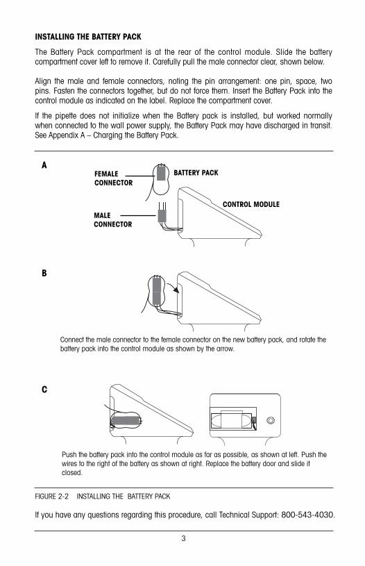
INSTALLING THE BATTERY PACK
The Battery Pack compartment is at the rear of the control module. Slide the batterycompartment cover left to remove it. Carefully pull the male connector clear, shown below.
Align the male and female connectors, noting the pin arrangement: one pin, space, twopins. Fasten the connectors together, but do not force them. Insert the Battery Pack into thecontrol module as indicated on the label. Replace the compartment cover.
If the pipette does not initialize when the Battery pack is installed, but worked normallywhen connected to the wall power supply, the Battery Pack may have discharged in transit.See Appendix A – Charging the Battery Pack.
FIGURE 2-2 INSTALLING THE BATTERY PACK
3
BATTERY PACK
MALE CONNECTOR
FEMALE CONNECTOR
CONTROL MODULE
Connect the male connector to the female connector on the new battery pack, and rotate thebattery pack into the control module as shown by the arrow.
Push the battery pack into the control module as far as possible, as shown at left. Push thewires to the right of the battery as shown at right. Replace the battery door and slide itclosed.
If you have any questions regarding this procedure, call Technical Support: 800-543-4030.
A
B
C
9920-313reva.qxd 4/5/04 11:37 AM Page 5

4
Basic Operation 3
EDP1 can operate in five modes:
MODE KEY DESCRIPTION
P: PIPETTE F 1 A single volume is picked up and dispensed.
M: MULTIPLE F 2 A single volume is picked up and multipleDISPENSE volumes dispensed stepwise.
T: TITRATE F 3 A single volume is picked up and partially dispensed under trigger control.
D: DILUTE F 4 Diluent, an air gap, and sample are picked upseparately and dispensed together.
MEAS: F 5 A sample is picked up under trigger controlMEASURE and its volume is displayed.
Modes are selected in EDP1 by pressing the F key and anumber key as shown in the table above. The keyboardshows the name or initial of the mode. See Figure 3-2:
The instrument powers up in PIPETTE mode. You can change modes when:
1. The piston is in the HOME position and KB is displayed. (If necessary, press theFUNCTION key F and then 0 to clear the current operation and move the piston to HOME.KB should then appear on the display.)
2. The keyboard is not locked. (Press F 9 to unlock.)
To change modes press F then the appropriate number key. For example, to open TITRATEmode press F 3. For MULTIPLE DISPENSE mode, press F 2.
The EDP1 pipette has been designed to be easy to use whether you are right- or left-handed. The balance, weight, comfortable “feel”, and light touch of EDP1 make it ideal forcontinuous use.
Hold EDP1 loosely in either hand – you do not need to grip the pipette tightly duringoperation. Operate the trigger with your index finger and the tip ejector button with yourthumb. Because there is no need for thumb pressure during pick up, dispense, andblowout, operator fatigue and the risk of repetitive strain injury are greatly reduced comparedto manual pipettes.
Table 3.1 – EDP1 Basic Operation
FIGURE 3-1 EDP1 KEYBOARD
9920-313reva.qxd 4/5/04 11:37 AM Page 6

AUTO SHUT-OFF
The EDP1 pipette shuts itself off automatically if none of the keys or the trigger are pressedfor three minutes. If the display is blank and the trigger does not work while power issupplied, EDP1 is shut off. Press any of the top row keys or E to turn on the instrument.
EDP1 remembers current operational settings when “shut-off”, and will resume operation atthe same point and with the same settings as when last used, as long as power to theinstrument has not been interrupted.
The AUTO SHUT OFF feature is provided to extend the life of the Battery Pack.
BASIC OPERATION
The examples used in this manual show the display for E-1000 (EDP1 with 1000 µLnominal volume). Your instrument will operate in the same way, but volumes shown will bedifferent if your pipette has a different nominal volume.
Attach a disposable tip by pressing the liquid end shaft firmly into the tip. Use water as yoursample until you are familiar with the EDP1 pipette.
QUICK REFERENCE: PIPETTE MODE
F 7 8 9
654
3210
.
E
V SEQ L S
D MEAS M I X
C P M T
FIGURE 3-2 RESUMING OPERATION AFTER AUTO SHUT-OFF
5
PISTONPOSITION
UP
HOME
DOWN
Ready Pick up Dispense Blowout Ready
BEEP BEEP BEEPBEEP
TRIGGER> > > TRIGGER> > > PAUSE > > > PAUSE > > >
Holding in thetrigger delaysthis step
Press any key in this rowor E When EDP1 is shut off
9920-313reva.qxd 4/5/04 11:37 AM Page 7

PIPETTE MODE F 1
When power is supplied, EDP1 executes a five-second initialization sequence and opens inPIPETTE mode. The display will show the nominal volume.
SETTINGS
Press number keys then the E (Enter) key to change the volume. The display will flash onand off. If you make a mistake, set a new volume then press E.
OPERATION
1. Press and release the trigger* to pick up the displayed volume. You will hear a “beep” atthe end of the piston stroke. See diagram on previous page.
2. Press and release the trigger again to dispense the liquid.
The piston moves to HOME, then rapidly executes a blowout stroke. You will hear a beep atthe end of the blowout. After a one-second delay the piston returns to HOME ready for thenext pickup. This is signalled by two beeps**.
The one-second delay is to give you time to remove the tip from the dispense vessel beforethe piston returns to HOME position. You can extend the delay by holding in the trigger asthe sample is dispensed. When EDP1 is in any other mode, open PIPETTE mode as follows:
a. Press F 0. This action will clear the current operation and move the piston to HOMEposition. KB will show on the display, indicating the piston is HOME. (Check that thekeyboard is not locked. If locked, press F 9 to unlock it.)
b. Press F 1 to open PIPETTE mode. The display will show the nominal volume unless you have previously set a volume inPIPETTE mode. (In all modes, any previously entered volume is remembered by EDP1 aslong as power is supplied continuously.)
PICKUP VOLUME DISPENSE VOLUME
* Holding in the trigger postpones the next step in all modes except TITRATE, MEASURE, and MIX.** Each piston stroke is signalled by a short beep when the tone generator is turned on.
End-of-stroke beeps will not be included in the following descriptions.
6
PICKUP
KB 475µlDISPENSE
475µl
9920-313reva.qxd 4/5/04 11:37 AM Page 8

QUICK REFERENCE: MULTIPLE DISPENSE MODE
MULTIPLE DISPENSE MODE F 2
Make sure the piston is at the HOME position (KB shows on display) and the keyboard isnot locked. Open MULTIPLE DISPENSE mode by pressing F 2 .
SETTINGS
1. The nominal pickup volume (or previously stored value) is displayed. Press E to checkor change the dispense volume.
2. Press number keys to set or change the dispense volume. While pressing keys, the entryflashes until E is pressed. See DISPENSE VOLUME, below.
3. The instrument calculates and flashes the largest number of whole aliquots which willdivide into the nominal volume. You can accept this aliquot number by pressing E , or youcan change to a smaller number by pressing number keys, then E.
7
PISTONPOSITION
UP
HOME
DOWN
Ready Pick upDispenseMultiple Blowout Ready
BEEP BEEP (AFTEREACH ALIQUOT)
BEEP BEEP
BEEPBEEP
TRIGGER> > >REPEATTRIGGER> > > CLEAR > > > PAUSE > > >
PICKUP
1000µlKB
MULTI
235µlKB
MULTI DISPENSE
4KB
MULTI
MULTIPLE DISPENSE NOMINAL VOLUME
DISPENSE VOLUME NUMBER OF ALIQUOTS (FLASHING)
1000µl
235µl 4
9920-313reva.qxd 4/5/04 11:37 AM Page 9

4. The instrument calculates and displays the volume needed to pick up all aliquots.
OPERATION
1. Press and release the trigger to pick up the displayed volume.
2. Press and release the trigger again to dispense the first aliquot. Continue pressing andreleasing the trigger until all aliquots are dispensed. The word CLEAR will appear on thedisplay.
3. Press 0 to clear the instrument, discarding the residual volume left in the tip.
After the dispense volume is entered, EDP1 calculates the pickup volume:
Pickup Volume = (Number of Aliquots x Dispense Volume) + Residual Volume
When the calculated volume is picked up, the piston slightly overshoots and thenreturns to its proper pickup position, to ensure accuracy of the first aliquotdispensed. To ensure that the last aliquot will be accurate, the fixed residualvolume remains in the tip after all aliquots have been dispensed and must bediscarded by pressing 0 before making the next pickup stroke.
QUICK REFERENCE: TITRATE MODE
8
PICKUP
940µlKB
MULTI
TOTAL PICKUP VOLUME
PISTONPOSITION
UP
HOME
DOWN
Ready Pick up TitrateDiscard remainder and Blowout Ready
BEEP
READ VOLUMEDISPENSED
BEEP
BEEPBEEP
TRIGGER> > >TAP or HOLDTRIGGER> > >
F 0 toCLEAR > > > PAUSE > > >
940µl
9920-313reva.qxd 4/5/04 11:37 AM Page 10

TITRATE MODE F 3
Make sure the piston is at the HOME position (KB shows on display) and the keyboard isnot locked.
Open TITRATE mode by pressing F 3 .
SETTINGS
1. The display shows the nominal pickup volume.To change the pickup volume, enter a new initialpickup volume with the number keys and press E .
2. To set an initial dispense volume, press numberkeys then press E . (To set an initial dispensevolume without changing the initial pickup volume,press E first. Enter the volume with number keys.Then press E again.)
OPERATION
1. Press and release the trigger to pick up the initial volume.
2. To begin titration, press and hold the trigger to dispense liquid first slowly, then at anincreasing rate. The longer the trigger is held, the faster the liquid is dispensed. Releaseand hold in the trigger again to restart dispensing at the slowest rate. To dispense oneincrement at a time, tap the trigger.
3. When the desired endpoint is reached, read and record the dispensed volume from thedisplay. Then clear the instrument by pressing F 0 . This will discard the remainder inthe tip and return EDP1 to its starting position.
If the entire volume is titrated, press the 0 key when the beep sounds and the displayreads “CLEAR”. This action will execute the blowout stroke and empty the residual volumefrom the tip.
In TITRATE mode, a small residual volume is left in the tip after the entire volume has beentitrated. The residual volume ensures that the volume titrated is accurate.
The residual volume is not part of the titrated volume and must be discarded bypressing F 0 .
9
TITRATE NOMINAL VOLUME
INITIAL PICKUP VOLUME SET
INITIAL DISPENSE VOLUME SET
TITRATE
PICKUP
KB1000µl
TITRATE
PICKUP
KB 560µl
TITRATE
KB150µl
DISPENSE
9920-313reva.qxd 4/5/04 11:37 AM Page 11

QUICK REFERENCE: DILUTE MODE
DILUTE MODE F 4
Make sure the piston is at the HOME position (KB shows on display) and the keyboard isnot locked. Press F 4 to open DILUTE mode. The display will show the default diluentvolume, which is 90% of nominal volume. (The default sample volume is 10% of nominalvolume, for 10:1 dilution.)
SETTINGS
1. Set the diluent volume (V1) by pressing number keys then E .
2. Set the sample volume (V2) in the same way.
OPERATION
1. Press and release the trigger to pick up the diluent.
10
PISTONPOSITION
UP
HOME
DOWN
ReadyPick upDiluent V1 Dispense Blowout Ready
BEEP BEEP BEEPBEEPBEEP
DILUENT
AIR GAP
SAMPLE
BEEP BEEPBEEP
TRIGGER> > > PAUSE > > > PAUSE > > >
Pick upAir
TRIGGER> > >
Pick upSample V2
TRIGGER> > > TRIGGER> > >Holdingtriggerdelays thisstep
500µlKB
DILUTE
V1
100µl
DILUTE
V2
KB
PICKUP
500µlKB
DILUTE
V1
DILUENT VOLUME
SAMPLE VOLUME
PICK UP DILUENT VOLUME
500µl
500µl
100µl
9920-313reva.qxd 4/5/04 11:37 AM Page 12

2. Press and release the trigger to pick up an air gap*.
3. Press and release the trigger a third time to pickup the sample.
4. A three-part tone sounds, indicating that diluentand sample are separated by the air gap, ready tobe dispensed. Press and release the trigger todispense diluent and sample.
5. The display shows the diluent volume, ready for the next cycle.
QUICK REFERENCE: MEASURE MODE
11
DISPENSE DILUENT AND SAMPLE TOGETHER
A i r
PICKUP
100µl
DILUTE
DISPENSE
600µl
DILUTE
V2
PISTONPOSITION
UP
HOME
DOWN
Ready Pick upDiscardremainder Blowout Ready
READ VOLUME MEASURED
BEEP BEEPBEEP
TAP or HOLDTRIGGER> > > PAUSE > > > PAUSE > > >
F 0 toCLEAR > > >
Holdingtriggerdelays thisstep
* When using DILUTE mode with the 5 mL, 10mL, and 20 mL EDP1 models, the air gap willprobably rise through the diluent and allow diluent and sample to mix in the sample reservoir. Toavoid this, you can use VOLUME SEQUENCING in DILUTE mode. Then set a smaller air gap, or nogap, as desired. See Section 6 — Advanced Operation: VOLUME SEQUENCING.
NOTES :1. An initial pickup volume can be set.2. Piston direction can be changed by pressing 0 , even while the trigger is pressed.3. At full stroke (or at zero) the trigger must be released. 3. Then either press F 0 to clear the pipette, or press the trigger again to reverse piston direction.
9920-313reva.qxd 4/5/04 11:37 AM Page 13

MEASURE MODE F 5
Make sure the piston is at the HOME position (KB shows on display) and the keyboard isnot locked. Press F 5 to open MEASURE mode.
SETTINGS
The display reads “0µl” (or any previously entered initial pickup volume). You can enter aninitial pickup volume if you wish by pressing number keys then E .
OPERATION
1. Press and hold the trigger to pick up. Pickup speed increases until it reaches themaximum. Release the trigger and press it again to restart at the slowest rate. To pick upone increment at a time, tap the trigger. (Any initial pickup volume is picked up at the firsttrigger press. Hold the trigger in to continue measurement.)
When the desired volume of liquid has been picked up, ensure the lower level of the liquidis flush with the tip orifice (no air has been included) and read the volume on the display.
The piston direction can be reversed at any time by pressing 0 . (This is useful if an airbubble is picked up; pressing 0 reverses the flow, expelling the bubble. Pressing 0again reverses flow and continues measurement.) The display always shows the currentvolume in the tip as well as the piston direction, either PICKUP or DISPENSE.
2. At full- or zero-scale, the display reads “CLEAR” and the trigger must be released.
Press the trigger again to reverse direction automatically. (The pipette may be cleared andthe tip contents dispensed by pressing F 0 ; this is useful if the volume of liquid to bepicked up exceeds the full-scale volume of the instrument.)
TONE GENERATOR CONTROL F 8
A tone generator in the EDP1 signals operational status or error conditions as follows:
Status Tone sound Tone description
Initialization BEEP-BEEP Two short beepsKey press BIP One very short beepEnd of pickup stroke BEEP One short beepEnd of dispense stroke BEEP One short beep (lower tone)Piston at HOME BEEP-BEEP Two short beepsEnd of pickup in DILUTE mode BEEP-BEEP-BEEP Two short, one long beepError condition/Low battery* DEE-DAH-DEE-DAH High warble
Tones are automatically switched on when the instrument is powered up. To switch off thetones, press F 8 . Pressing F 8 again turns the tone generator back on.
12
Optional Settings 4
* Works even when tone generator is OFF
9920-313reva.qxd 4/5/04 11:37 AM Page 14

KEYBOARD LOCK CONTROL F 9
The EDP1 keyboard can be locked if desired. This feature is for protection. Locking thekeyboard prevents unwanted volume or mode changes when the EDP1 is used for the sametask over an extended period.
To lock the keyboard, press F 9 when the keyboard is active (when KB is displayed).Press F 9 again to unlock the keyboard. When the keyboard is locked, all keystrokes areignored excep F 0 (clear), F 8 (tone generator control), and F 9 (keyboardlock/unlock). The trigger operates whether the keyboard is locked or unlocked.
PROGRAMMABLE SPEED F •
You can program the pickup and dispense speed of the EDP1 pipette to accommodatealmost any liquid, including moderately dense or viscous liquids.
The default speed setting for EDP1 pipettes is 8*. This fast setting is optimized for liquidswith similar physical properties to water. However, you may wish to set a higher speed foreven faster operation or a slower speed for more dense or viscous liquids.
To reset the speed, press F • (decimal point) then press a number between 0 and 9, thenpress E . The display reverts to show volume after speed has been set. The table belowshows cycle component times for available speed settings.
Table 5.1 – EDP1 Programmable Speeds
Speed Full-Scale Full-Scale Delay before Blowout Dwell TimeSetting Pickup Dispense Blowout duration (constant)
9 1.3 sec. 1.3 sec. 0.0 sec. 0.13 sec. 1.0 sec.
8 1.3 sec. 1.3 sec. 0.5 sec. 0.13 sec. 1.0 sec.
7 1.3 sec. 1.3 sec. 1.0 sec. 0.13 sec. 1.0 sec.
6 2.2 sec. 2.2 sec. 0.5 sec. 0.22 sec. 1.0 sec.
5 2.2 sec. 2.2 sec. 1.0 sec. 0.22 sec. 1.0 sec.
4 2.2 sec. 2.2 sec. 1.5 sec. 0.22 sec. 1.0 sec.
3 2.2 sec. 2.2 sec. 2.0 sec. 0.22 sec. 1.0 sec.
2 4.4 sec. 4.4 sec. 0.5 sec. 0.44 sec. 1.0 sec.
1 4.4 sec. 4.4 sec. 1.0 sec. 0.44 sec. 1.0 sec.
0 4.4 sec. 4.4 sec. 2.0 sec. 0.44 sec. 1.0 sec.
This table does not apply to trigger-controlled actions in TITRATE and MEASURE modes.
13
Setting Speed 5
* Default speed setting for EDP1 10 mL, 20 mL models is 5. Speed range is 0 – 6.
9920-313reva.qxd 4/5/04 11:37 AM Page 15

14
Advanced Operation 6
Table 6.1 – EDP1 Advanced Functions
FUNCTION KEY DESCRIPTION APPLICABLE MODE
MIX F 6 Mixes by repeated up-and- P – PIPETTEdown piston motion while D – DILUTEtrigger is held in
VOLUME F 7 PIPETTE: up to 12 distinct P – PIPETTESEQUENCING volumes can be picked up
and dispensed sequentially.
MULTIPLE DISPENSE: up M – MULTIPLE DISPENSEto 12 distinct volumes can be dispensed sequentially from a single pickup volume.
DILUTE: up to 12 distinct D – DILUTEvolumes can be picked up sequentially and dispensedtogether.
MIX F 6 Available in PIPETTE and DILUTE modes only.
SETTINGS
1. Open the MIX function by pressing F 6 .
2. The display prompts you for a mix volume*. Enter this volume and press E .
OPERATION
IN PIPETTE MODE: 1. Press and release the trigger to aspirate the pickup volume. Pressthe trigger again to dispense.
IN DILUTE MODE: 1. Press and release the trigger to pick up the diluent. Press andrelease the trigger to pick up an air gap, and again to pick up the sample. When the three-part tone sounds, press the trigger once more to dispense diluent and sample together.
MIX VOLUME ENTERED
* The mix volume may be larger than the pickup or diluent/sample volumes.
KB200µl
VMIX
9920-313reva.qxd 4/5/04 11:37 AM Page 16

2. Hold the trigger (either during or after the dispense stroke) to start mixing. Mixing willcontinue as long as the trigger is held in. The display alternates between PICKUP andDISPENSE while mixing is in progress.
3. Release the trigger. Mixing stops and a normal blowout stroke occurs. The displayshows the pickup or diluent volume, ready for another cycle.
4. To close the MIX function press F 6 .
VOLUME SEQUENCING F 7 in PIPETTE, MULTIPLE DISPENSE, and DILUTE modes.
VOLUME SQUENCING: PIPETTE MODE
In PIPETTE mode, up to twelve distinct volumes can be picked up and dispensedsequentially with VOLUME SEQUENCING.
When using this function, you are not restricted to the fixed sequence: by pressing theF 0 keys you can go back and repeat the previous volume, or by pressing E you canskip over the next volume. The sequencing cycle can be started at any point. Open theVOLUME SEQUENCING function by pressing F 7 .
SETTINGS
Display flashes “0µl” (or the volume last set). Set the first pickup / dispense volume (V1) bypressing number keys followed by E . Continue setting sequential pickup/dispensevolumes. Press 0 E to end the sequence. If you enter all twelve volumes, you do nothave to press 0 to end the sequence. Sequential volumes are numbered as follows: V1–9, then VA (10), Vb (11), & VC (12).
OPERATION
1. Press and release the trigger to pick up the current volume.
MIXING IN PROGRESS; MIX VOLUME ALTERNATELY PICKED UP AND DISPENSED
15
PICKUP
200µlVMIX
DISPENSE
200µlVMIX
FIRST VOLUME PICKED UP
KB
PICKUP
100µl V1
SEQ
9920-313reva.qxd 4/5/04 11:37 AM Page 17

2. Press and release the trigger to dispense the current volume.
3. Press and release the trigger to pick up the next sequential volume.
4. Press and release the trigger to dispense the next sequential volume. Continue in thisway until all volumes are picked up and dispensed.
5. After the last volume in the sequence is dispensed, the first volume is displayed again,ready for pickup.
6. To close the VOLUME SEQUENCING function, press F 7 .
VOLUME SEQUENCING: MULTIPLE DISPENSE MODE
In MULTIPLE DISPENSE mode with VOLUME SEQUENCING, up to 12 distinct volumes can bedispensed sequentially from one pickup volume. Open the VOLUME SEQUENCING feature bypressing F 7 .
SETTINGS
1. The display flashes “0µl” (or the volume last set). Enter the first volume (V1) with thenumber keys and press E .
2. The display flashes “0µl” again, prompting you for the next volume. Enter the secondvolume (V2) and continue in the same way for each entry, finishing each entry withE and the last entry with 0 E . Sequential volumes are numbered as follows: V1–9, thenVA (10), Vb (11), & VC (12).
3. The EDP1 pipette calculates and displays the number of cycles, or the largest number oftimes the sum of the volumes will divide into the nominal volume of the instrument. Acceptthe number of cycles by pressing E , or set a smaller number and press E . (Setting alarger number will sound an error alarm.)
OPERATION
1. The display will show the volume to be picked up; press and release the trigger to pickup that volume.
1ST VOLUME DISPENSED
2ND VOLUME PICKED UP
16
DISPENSE
100µl V1
SEQ
KB
PICKUP
150µl V2
SEQ
9920-313reva.qxd 4/5/04 11:37 AM Page 18

2. Press and release the trigger again to dispense the first sequential volume. Press andrelease the trigger again to dispense the second sequential volume, and so on.
3. After all sequential volumes in the first cycle have been dispensed, press the trigger tobegin the second cycle. Continue until all cycles are complete.
4. The display will read “CLEAR” after the last dispense volume in the last cycle. Press 0to clear the instrument.
5. To close the VOLUME SEQUENCING function, press F 7 .
VOLUME SEQUENCING: DILUTE MODE
In DILUTE mode with VOLUME SEQUENCING, up to twelve distinct volumes can be pickedup sequentially and dispensed together. Open VOLUME SEQUENCING by pressing F 7 .
SETTINGS
1. Display flashes “0µl” (or volume last set). Press number keys then E to set the firstsequential volume (V1).
2. Display flashes “0µl” (or volume last set). Press number keys followed by E to set thenext volume (V2). Sequential volumes are numbered as follows: V1–9, then VA(10), Vb (11), & VC (12).
3. Continue in this way until all volumes are set. Press 0 E to end the sequence.
OPERATION
1. The display shows the first pickup volume. Press and release the trigger to pick up thefirst volume (V1).
2. Press and release the trigger again to pick up the next volume (V2). Air gaps are notautomatically added when VOLUME SEQUENCING. If you wish, air gaps can be set asvolume entries.*
3. Continue in this way until all volumes are picked up.
4. A three-part tone sounds. Press the trigger to dispense the total volume all at once.
5. The display shows the first pickup volume again. Press and release the trigger to pick upvolume V1 and restart the cycle.
6. To close the VOLUME SEQUENCING function, press F 7 .
17
* This is a good way to avoid the potential problem when using DILUTE mode with the 5 mL,10mL, and20 mL EDP1 models — where the air gap can rise through the diluent, allowing diluent and sample tomix in the sample reservoir. You can set a smaller air gap which will stay in place between the diluentand sample, or no gap at all. See Section 3 — Basic Operation, DILUTE mode.
9920-313reva.qxd 4/5/04 11:37 AM Page 19

18
Proper Pipetting Technique 7
Use RAININ tipsEDP1 pipettes are designed for use with RAININ-manufactured disposable tips. Specifiedperformance of EDP1 pipettes is guaranteed only when RAININ disposable tips are used.RAININ cannot accept responsibility for damage to EDP1 pipettes or for poor performanceresulting from the use of other than RAININ disposable tips.
RAININ molds its own disposable tips from premium-grade virgin polypropylene plastic inan advanced clean-room environment. Molds are inspected and maintained frequently toassure high-quality tip production. Samples from each lot of tips are inspectedmicroscopically to assure that every lot meets these high standards. To order tips for EDP1pipettes, please refer to the RAININ Pipetting Solutions Catalog or the current RAININProduct Update. Call 800-543-4030 for a free copy of these publications. You can alsoview or download a PDF version online: http://www.rainin.com/lit_prodlit.asp
Pipetting techniques
EDP1 pipettes are designed to deliver accurate and precise measurements under thefollowing conditions:
1. The liquid pipetted is water or liquid with density, viscosity, and vapor pressure similar towater. The temperature of the room, the EDP1, and the liquid, are all in the range 21.5°C ±1°C. The EDP1 pipette is kept vertical while pipetting or within 20° of vertical.
2. The end of the disposable tip is immersed beneath the sample surface as follows:2 to 3 mm – volumes up to 100 µL.2 to 4 mm – volumes from 100 µL to 1000 µL. 3 to 6 mm – volumes from 1000 - 5000 µL.6 to 10 mm – volumes over 5000 µL
3. There is no significant adherence of liquid to the surfaces of the tip. (Each tip should bepre-rinsed twice before pipetting to assure the best reproducibility).
4. When dispensing, the tip is touched to the sidewall of the receiving vessel. At the end ofeach dispense cycle, the tip is moved along the wall to remove any excess sample from theoutside of the tip. A consistent rhythm is maintained from sample to sample when pipetting.
Viscous liquids, such as serum or plasma, can be measured accurately with a slow speed.See Table 5.1 – Programmable Speeds. You can further improve accuracy with viscoussolutions by using MULTIPLE DISPENSE mode with the number of aliquots set to 1 andusing a slow speed. This method simulates “reverse-mode” pipetting in manual pipettes. InMULTIPLE DISPENSE mode, the volume picked up includes an extra residual volume andthe volume of the dispensed aliquot is accurate.
You can measure warm or cold liquids with good precision by using a consistent pipettingrhythm. A consistent rhythm will help minimize any differences in heating or cooling effectswithin the pipette. Use a new disposable tip each time for best accuracy and precision whenmeasuring samples with temperatures greatly different from ambient, and do not pre-rinse.
As with any air-displacement pipette, best results will be obtained if there is no delaybetween picking up the sample and dispensing it.
9920-313reva.qxd 4/5/04 11:37 AM Page 20

19
Removing the Tip Ejector Arm 8
Changing Liquid Ends 9
REMOVING THE TIP EJECTORThe tip ejector should be removed to change the liquid end on models up to 2000 µL (seeSection 9 below). It can also be removed if you wish to load and remove tips manually forpipetting into deep narrow vessels, especially on the larger-volume models. Three types oftip ejector are used and all are removed with minimum effort—do not use force.
For models up to 2000 µL, press in the quick-release tabs on the ejector arm and pull theejector down. For 5000 µL & 10 mL models, twist the end of the ejector arm and pulldownward. For 20 mL models, pull the lower part of the tip ejector away from the upperpart (do not remove the upper part).
To replace the ejector arm (after changing the liquid end) on all models except 20 mL,insert the shaft through the large opening, align the top with the tip ejector pushrod, andpush until the ejector arm snaps in place. For 20 mL models, place the large opening overthe shaft and align the rod in the lower part of the tip ejector with the hole in the upper partand press firmly.
The liquid ends for models up to 2000 µL are interchangeable. Liquid ends are notinterchangeable on 5000 µL, 10 mL and 20 mL models.
When changing a liquid end, you must also change the encoder plug on the controlmodule, to signal the liquid end volume to the software. Both the encoder plug and the shaftare marked with the nominal volume. LTS shafts are used with encoder plugs marked LTSand the nominal volume. Traditional shafts are used with encoder plugs marked with thenominal volume only.
Before removing the liquid end, bring the piston to HOME by pressing F 0 . The letters KBshould appear on the display. If the keyboard is locked, unlock it (press F 9 ).
FIGURE 8-1 REMOVING THE TIP EJECTOR ARM
Up to 2000 µL 5000 µL, 10 mL 20 mL
9920-313reva.qxd 4/5/04 11:37 AM Page 21

TO REMOVE THE LIQUID END
1. Referring to Figure 9-1A , loosen the shaft coupling by rotating it counter-clockwise.
2. When the shaft coupling is free of the threads, remove the shaft coupling. The motorshaft is connected to the piston assembly by a ball-joint. This ball-joint must bedisconnected before proceeding, as follows:
a. pull the liquid end away from the control module enough to reveal the end of themotor shaft – see Figure 9-1B. The spring and clear plastic spring holder can be leftin place: they will not interfere with this procedure.
b. angle the liquid end and ease the ball-joint out of the socket – see Figure 9-1C.
3. Remove the encoder plug from the control module (seeFigure 9-2) and store it with its matching liquid end. Liquidmeasurements made with the EDP1 will be accurate andprecise ONLY when the correct liquid end/encoder plugcombination is used.
NOTE: Before storage, disassemble the liquid end (see Section 10) andinspect for salts or residues. Clean the liquid end and store it with itsencoder plug and tip ejector arm in the two tubes provided with thereplacement liquid end.
Do not touch the underside of the plug; skin oils can contaminate it,causing poor electrical contact and erratic performance. The plug can becleaned with isopropanol.
20
FIGURE 9-1 REMOVING THE LIQUID END (NOTE THE BALL-JOINT CONNECTION IN B & C)
FIGURE 9-2 REMOVINGTHE ENCODER PLUG
A B C
BALL-JOINTIN SOCKET
BALL-JOINT
9920-313reva.qxd 4/5/04 11:37 AM Page 22

REINSTALLING THE LIQUID END
CAUTION: Always attach the replacement liquid end BEFORE inserting the encoder plug.
1. The replacement liquid end is supplied in a clear plastic tube together with a second tubeholding the matching tip ejector and encoder plug. Make sure you have all threecomponents. The spring and spring guide extend from the liquid end as shown in Figure9-3A. It is a good idea to pull back the spring and spring guide so that the ball-joint andsocket connection area is clear, to help in reattaching the ball-joint to the piston shaft.
2. Bring the liquid end and the control module together so that the ball-joint aligns with thesocket in the top of the piston shaft as shown in Figure 9-3B. Note the extension at theend of the ball-joint – see arrow.
3. Carefully connect the ball-joint on the motor drive into the socket on the piston shaft. Youmay need to maneuver the small extension downward to fully engage the two pieces,shown connected in Figure 9-3C. Once the angle is correct, the ball and socket will jointogether easily. DO NOT USE FORCE. Once the joint is made straighten the liquid end andcontrol module then release the spring and spring guide.
4. Hold the liquid end and control module together and thread the shaft coupling onto thecontrol module. Ensure the threads engage properly, and hand-tighten the shaft couplingonto the control module.
5. Take the replacement encoder plug. Make sure the labels onthe plug and liquid end match.
6. Align the encoder plug with its slot in the head of the controlmodule (avoid touching the bottom of the plug) and insert theplug squarely – see Figure 9-4. If power is supplied to theEDP1 and the keyboard is unlocked, the initializationsequence begins when the encoder plug is in place.
7. After the initialization sequence, look at the display. The EDP1 pipette should be inPIPETTE mode with the display reading PICKUP. The nominal volume of the liquid end isalso displayed, as shown in Figure 9-5. (If your display does not show the propernominal volume, check that the correct encoder plug is installed.)
21
FIGURE 9-3B REPLACINGTHE LIQUID END (2)
FIGURE 9-3A REPLACINGTHE LIQUID END (1)
FIGURE 9-3C REPLACINGTHE LIQUID END (3)
FIGURE 9-4 REPLACINGTHE ENCODER PLUG
PICKUP
1000µlKB
FIGURE 9-5DISPLAY AFTER INITIALIZATION SEQUENCE (E1-1000 SHOWN)
SPRING
PISTON
SPRING GUIDE
SHAFT
BALL-JOINTEXTENSION
1000µl
9920-313reva.qxd 4/5/04 11:38 AM Page 23

22
Care and Maintenance 10EDP1 pipettes are designed to need very little maintenance and should give years oftrouble-free service if treated with proper care and the operating recommendations in thismanual are followed. Also see: RAININ Publication AB-15, Procedure for EvaluatingAccuracy and Precision of RAININ Pipettes, available on the Rainin website athttp://www.rainin.com/pdf/ab15.pdf
The following rules should be strictly observed to keep the mechanism dry and clean.
1. Never allow liquid to enter the shaft where it can contact the piston or seal.
2. Never pick up liquid without a disposable tip attached.
3. Never invert EDP1 or lay it on its side with liquid in the tip. Always hold it upright.
4. Never use solvents to clean EDP1. Instead, use a lint-free wipe dampened with water toclean the instrument. Keep the keyboard and encoder plug dry.
SEALING
Periodically each liquid end should be tested to ensure proper sealing, as follows:
1. Set the nominal volume and attach a disposable tip.
2. Pick up the full volume of water.
3. Hold the instrument upright and observe the tip for 30 to 45 seconds.
There should be no leaks from the tip or droplet formation at the tip orifice. If leakage doesoccur, sealing between the tip and the shaft may not be airtight.
SHAFT AND TIP SEALING
Use only RAININ disposable pipette tips. These tips mate exactly with the EDP1 liquid endshaft to form airtight sealing, necessary for air-displacement pipettes to operate.
PISTON SEALINGSealing between the piston and the inside surface of the shaft is performed by a PTFE sealand a Buna O-ring. The PTFE seal extends through the O-ring, and only the PTFE sealmakes contact with the piston. The O-ring compresses the PTFE seal against the piston tomaintain proper sealing even after moderate wear, and also provides stationary sealingbetween the PTFE seal and the shaft. Figure 10.1 shows a detailed view of the liquid end,with each component separated for clarity.
FIGURE 10-1 DETAIL VIEW OF EDP1 LIQUID END (200 µL SHOWN)
SPRING SPRING GUIDE
PISTON ASSEMBLY
SEAL RETAINER
PTFE SEAL
O-RING
SHAFT SHAFT COUPLING
9920-313reva.qxd 4/5/04 11:38 AM Page 24

23
A close-up detail of the 200 µL piston sealassembly is shown in Figure 10-2: the seal retainercan appear very different in other models.
Periodically you should dismantle the liquid end forinspection and cleaning, as follows:
1. Remove the liquid end from the control moduleas described in Section 9. Do not remove theencoder plug for this procedure.
2. Pull the piston assembly out of the liquid end.The PTFE seal and o-ring should stay attached tothe piston. If they remain in the liquid end, invertthe liquid end and gently tap it on the bench untilthe seal assembly drops out.
3. Inspect the piston, PTFE seal and o-ring, seal retainer, and inside of the shaft for any dirtand particulate contamination. Do not dismantle the piston assembly any further.
4. Remove any contamination by soaking and rinsing the piston assembly with distilledwater or alcohol. The piston surface should have a high-gloss finish. If the finish is dull,scratched, or pitted, the PTFE seal may wear very rapidly, and the complete pistonassembly should be replaced.
5. Blow the assembly dry with clean dry compressed nitrogen, or dry it with a very soft lint-free wipe. To avoid scoring the piston, do not use rough material such as a paper towel.
CAUTION: Never apply grease to the piston or seal assembly (except on the 5 mL, 10 mL, and 20 mL models, which use a grease seal). For EDP1pipettes with nominal volumes below 5 mL, any grease or lubricant may alterthe effective diameter of the piston and cause liquid measurement errors.
REASSEMBLY
1. Make sure the PTFE seal and o-ring are properly positioned on the piston.
2. Follow the procedure in Section 9 to replace the liquid end.
3. Attach a disposable tip, and test for proper sealing as described in the first part of thischapter.
AUTOCLAVING
The autoclavable parts of EDP1 are the shaft and the tip ejector*: at a tempereature of121°C, pressure of 1 bar, for a maximum duration of 15-20 minutes.
DO NOT AUTOCLAVE THE COMPLETE PIPETTE OR ANY PARTS OTHER THAN THESHAFT AND THE TIP EJECTOR.
* DO NOT AUTOCLAVE THE TIP EJECTOR ON THE 20 mL MODEL
FIGURE 10-2 PISTON SEAL ASSEMBLY(200 µL SHOWN)
PISTON
SEAL RETAINER
PTFE SEAL
O-RING
9920-313reva.qxd 4/5/04 11:38 AM Page 25

24
Troubleshooting 11
Symptom Possible Cause Suggested Remedy*
Inaccurate liquid Bad seal between disposable tip Use RAININ disposable tipsmeasurement or leaks and liquid end
Damaged shaft end Replace shaft.
Inadequate seal on piston Check, clean, or replace assembly piston seal.
“Lob” on display, Insufficient charge in Battery Pack Recharge Batterywarbling alarm Pack; see Appendix B.
Blank display, no alarm EDP1 is shut off Press any top row key or E to turn on instrument.
Depleted Battery Pack Recharge BatteryPack; see Appendix B.
Wall power supply disconnected Reconnect cord to (when not using Battery Pack) EDP1 pipette.
Display reads “Err”, Illegal volume entered Enter legal volume.warbling alarm (will not be accepted)
Keyboard will not accept Keyboard locked Unlock keyboard byentries, “KB locked” on LCD pressing F 9.
If anything confusing happens during operation of the EDP1 pipette, it can sometimes beremedied by pressing F 0 (unless the display is flashing, indicating an entry must becompleted). Pressing F 0 returns the piston to HOME and activates the keyboard.
You can also reset the instrument by removing power, or removing and replacing theencoder plug. (The keyboard MUST be unlocked if you remove the encoder plug.) Thepipette will restart and reinitialize. It will be in PIPETTE mode at its nominal volume after thissequence. This remedy should be used only as a last resort, since all stored information willbe lost from the micro-computer and will need to be re-entered.
RAININ maintains service departments to correct any electro-mechanical problems with theEDP1 pipette, or problems resulting from physical or chemical damage. In the U.S.A. pleasecontact Technical Service at 800-543-4030 for more information and assistance.
Outside the U.S.A. contact the RAININ distributor for your country. If you do not know theaddress, call International Customer Service at 001-510-564-1614, or send e-mail [email protected].
RAININ distributors are also listed by country on the web: www.rainin-global.com/list.html
* If the suggested remedy does not correct the problem, contact RAININ at 800-543-4030.
Table 11-1 Troubleshooting
9920-313reva.qxd 4/5/04 11:38 AM Page 26

Specifications 12These manufacturer’s specifications should be used as guidelines when establishing yourown performance specification in accordance with ISO 8655.
Volume Increment Accuracy (Systematic Error) Precision (Random Error)EDP1 Model µL µL % µL (±) % µL (≤)
10 µL 1 0.01 2.5 0.025 1.2 0.012 5 1.5 0.075 0.6 0.03
10 1.0 0.1 0.4 0.0420 µL 2 0.02 7.5 0.15 2.0 0.04
10 1.5 0.15 0.5 0.0520 1.0 0.2 0.3 0.06
100 µL 10 0.1 3.5 0.35 1.0 0.150 0.8 0.4 0.24 0.12
100 0.8 0.8 0.15 0.15200 µL 20 0.2 2.5 0.5 1 0.2
100 0.8 0.8 0.25 0.25200 0.8 1.6 0.15 0.3
300 µL 30 0.2 2.5 0.75 1 0.3150 0.8 1.2 0.25 0.375300 0.8 2.4 0.15 0.45
1000 µL 100 1 3.0 3 0.6 0.6500 0.8 4 0.2 1
1000 0.8 8 0.15 1.52000 µL 200 2 3 6 0.6 1.2
1000 0.8 8 0.2 22000 0.8 16 0.12 2.4
5000 µL 500 10 2.4 12 0.6 32500 0.6 15 0.2 55000 0.6 30 0.16 8
10 mL 1 mL 10 5 50 0.6 65 mL 1 50 0.2 10
10 mL 0.8 80 0.16 1620 mL 2 mL 20 5 100 0.6 12
10 mL 1 100 0.2 2020 mL 0.8 160 0.16 32
Specifications are subject to change without notice, and apply to operation in PIPETTE mode.For ISO 8655 purposes, specifications can also be referred to as “Maximum Permissible Error”.
Electrical specifications This device is intended for use only with the power sources with RAININ part numbers listed below. Noother power sources may be used with this device.
Wall Power Supply Input: 6101-063 100-130 VAC 50-60 Hz (US/JAPAN)6100-064UX 210-260 VAC, 50-60 Hz (UK)6100-064EX 210-260 VAC, 50-60 Hz (EU)
Wall Power Supply Output: All P/Ns 6 VDC 100 mA Regulated Nominal
RCS Wall Transformer Supply Input: 6101-049 100-130 VAC 50-60 Hz (US/JAPAN)6101-048UX 210-260 VAC, 50-60 Hz (UK)6101-048EX 210-260 VAC, 50-60 Hz (EU)
RCS Wall Transformer Supply Output: All P/Ns 12 VAC 400 mA Regulated NominalBattery 6100-080 Ni-Cad 4.8 VDC Nominal 250 mAh NominalExplanation of symbols:A - Ampere, Hz - Hertz, mAh - Milliamp Hour, VAC - Volts Alternating Current, VDC - Volts DIrect Current
25
9920-313reva.qxd 4/5/04 11:38 AM Page 27

26
Recharging the Battery Pack A
Power is supplied to the EDP1 by either a wall power supply cord, or with a Battery Pack. Afully-charged Battery Pack will allow you to make up to 2000 full-stroke cycles beforecharging is needed, depending on the pipette volume range. If the Battery Pack dischargesduring operation, the EDP1 will sound a warning and the message “Lob” will be displayed.If this occurs, connect the EDP1 to a charger immediately after the current pipetting cycle. Ifyou connect to the wall power supply, you can continue operation without interruption.
The Battery Pack can only be charged when installed in EDP1, in either of two ways:
WALL POWER SUPPLY
Connect the wall power supply cord to the connector on the back of thecontrol module. Connect the power supply to an AC power source withthe correct line voltage as specified on the power supply. The wallpower supply can recharge a completely discharged Battery Pack inabout 14 hours.
RAPID CHARGE STAND
Connect the Rapid Charge Stand to a suitable AC power source withthe correct voltage (see paragraph above). Place EDP1 on the standso that the four contact pins engage the contact slots on the stand. Thedisplay reads “F C” (Fast Charge): functions are inoperative until EDP1is removed from the stand. The Rapid Charge Stand can recharge aBattery Pack in about 90 minutes. Current is metered precisely, and theBattery Pack temperature continually monitored via a built-in sensorprobe. When the Battery Pack is fully charged, the red charge indicatorlight on the Rapid Charge Stand goes out.
For extended storage of the EDP1, the Battery Pack should be fullycharged and removed from the instrument.
ABOUT NICKEL-CADMIUM BATTERIES
The Battery Pack uses NiCad batteries, ideal for use in this applicationbecause they are rechargeable with a long service life. However, all NiCads can developover time a “memory” or a propensity to seem fully charged at less than 100% of capacity.This is a gradual process unlikely to be noticed in normal usage. In the extreme, the unitcould display “Lob” at increasingly frequent intervals after recharging for the requisiteperiod.
To extend the life of the Battery Pack, fully drain the batteries from time to time. The low-battery alarm and the Lob display will alert you that it is time to recharge the batteries.
If you use a Rapid Charge Stand to rest the instrument, keep the Rapid Charge Standunplugged until you need to recharge the batteries. (Recharging takes about 1-1/2 hourswith the Rapid Charge Stand.)
FIGURE A-1CONNECTINGWALL POWERSUPPLY
FIGURE A-2RAPID CHARGESTAND
9920-313reva.qxd 4/5/04 11:38 AM Page 28

27
Ordering Information B
EDP1 pipettes, parts and accessories can be ordered online 24/7 at www.rainin.com, or byphone, mail, fax, or e-mail: 800-4-RAININ (800-472-4646) e-mail: [email protected]
Rainin Instrument, LLC.7500 Edgewater Drive, Box 2160, Oakland, CA 94621-0060 • FAX 510-564-1617Rainin Road, Box 4026, Woburn, MA 01888-4026 • FAX: 781-938-1152See back page for other countries.
Complete EDP1 Pipettes: Includes one Control Module, one Wall Power Supply, and oneLiquid End for the nominal volumes listed below.
Cat. No. Description LTS MODELS TRADITIONAL MODELSE1-10 SE1-10 EDP1 Electronic Pipette, 1-10 µLE1-20 SE1-20 EDP1 Electronic Pipette, 2-20 µLE1-100 SE1-100 EDP1 Electronic Pipette, 10-100 µLE1-200 SE1-200 EDP1 Electronic Pipette, 20-200 µLE1-300 SE1-300 EDP1 Electronic Pipette, 20-300 µLE1-1000 SE1-1000 EDP1 Electronic Pipette, 100-1000 µLE1-2000 SE1-2000 EDP1 Electronic Pipette, 200-2000 µLE1-5000 SE1-5000 EDP1 Electronic Pipette, 500-5000 µLE1-10ML SE1-10ML EDP1 Electronic Pipette, 1-10 mLE1-20ML n/a EDP1 Electronic Pipette, 2-20 mL
Control Module:E1-CM Control Module only, for all volumes
Interchangeable Liquid Ends: (Each is supplied with matching Encoder Plug)LTS MODELS TRADITIONAL MODELSE1-10LE SE1-10LE EDP1 Liquid End, 1-10 µLE1-20LE SE1-20LE EDP1 Liquid End, 2-20 µLE1-100LE SE1-100LE EDP1 Liquid End, 10-100 µLE1-200LE SE1-200LE EDP1 Liquid End, 20-200 µLE1-300LE SE1-300LE EDP1 Liquid End, 20-300 µLE1-1000LE SE1-1000LE EDP1 Liquid End, 100-1000 µLE1-2000LE SE1-2000LE EDP1 Liquid End, 200-2000 µL
Replacement Battery Pack:6100-080 Battery Pack for cordless operation.
(Rechargeable by Wall Power Supply or Rapid Charge Stand.)
Rapid Charge Stand:6101-049 Rapid Charge Stand for EDP1 Pipette, US/Japan6101-048UX Rapid Charge Stand for EDP1 Pipette, UK6101-047EX Rapid Charge Stand for EDP1 Pipette, Europe
Extra Wall Power Supply:6100-063 Wall Power Supply, 100-130V, 50-60Hz, US/Japan6100-064UX Wall Power Supply, 210-260V, 50-60Hz, UK6100-044EX Wall Power Supply, 210-260V, 50-60Hz, Europe
9920-313reva.qxd 4/5/04 11:38 AM Page 29

Replacement Parts (Refer to drawings opposite)A: Shaft Coupling B: Shaft C: Tip Ejector D: Piston Assembly E: Spring F: Spring Guide G: Seal Retainer H: Seal J: O-ring
Parts for E3-Series 10 µL to 2000 µL:
E1-10 E1-20 E1-100 E1-200 E1-300 E1-1000 E1-2000A 6107-063 6107-063 6107-063 6107-063 6107-063 6107-063 n/aB 6202-064 6202-065 6202-066 6202-067 6202-425 6202-068 6202-214C 6202-071 6202-071 6202-073 6200-156 6202-419 6200-163 6200-168D 6100-682 6100-683 6100-684 6100-685 6100-686 6100-687 6100-688E 6200-195 6200-197 6200-197 6200-199 6200-199 6107-108 6107-109F 6100-680 6100-680 6100-680 6100-680 6100-680 6100-680 6100-681G 6200-196 6200-198 6200-201 6200-200 6200-416 6107-106 6107-107H 6200-138 6200-143 6200-150 6200-154 6200-415 6200-161 6200-166J 6200-139 6200-170 6200-151 6200-155 6200-414 6200-162 6200-167
Parts for SE1-Series 10 µL to 1000 µL:
SE1-10 SE1-20 SE1-100 SE1-200 SE1-300 SE1-1000 SE1-2000A 6107-063 6107-063 6107-063 6107-063 6107-063 6107-063 n/aB 6200-140 6200-145 6200-147 6200-157 6200-413 6200-160 6200-169C 6200-133 6200-144 6200-148 6200-156 6200-419 6200-163 6200-168D 6100-682 6100-683 6100-684 6100-685 6100-686 6100-687 6100-688E 6200-195 6200-197 6200-197 6200-199 6200-199 6107-108 6107-109F 6100-680 6100-680 6100-680 6100-680 6100-680 6100-680 6100-681G 6200-196 6200-198 6200-201 6200-200 6200-416 6107-106 6107-107H 6200-138 6200-143 6200-150 6200-154 6200-415 6200-161 6200-166J 6200-139 6200-170 6200-151 6200-155 6200-414 6200-162 6200-167
Parts for E1 and SE1 series 5000 µL to 10 mL:A: Piston Assembly B: Piston o-ring C: CylinderD: Cylinder o-ring E: Shaft F: Tip Ejector Arm
5000 µL 10 mL 20 mLA 6100-689 6100-690 6100-691B 6107-112 6107-113 6202-299C 6200-365 6200-371 6202-301D 6200-364 6200-370 6202-300E E1 series 6202-222 6202-223 6202-302E SE1 series 6200-362 6200-368 n/aF 6200-373 6200-374 6202-298
Common parts for 5000 µL, 10 mL, and 20 mL E1 and SE1 series:
Tube of grease: 6100-555Filters for 5000 µL & 10 mL: 6190-164 (pkg of 100) 6190-165 (pkg of 1000)Filters for 20 mL: 6190-221 (pkg of 100) 6190-222 (pkg of 500)
28
FIGURE B-1 (OPPOSITE PAGE): LINE DRAWINGS OF EDP1 MODELS SHOWING REPLACEMENT PARTS
9920-313reva.qxd 4/5/04 11:38 AM Page 30

EDP1 10 µL and 20 µL EDP1 100 µL, 200 µL and 300 µL
EDP1 1000 µL and 2000 µL EDP1 5000 µL, 10 mL and 20 mL
A
B
C
D
E
F
G
HJ
A
B
C
D
E
F
GHJ
A
B
C
D
E
FG
H
F
A
B
C
D
E
Legend for EDP1 10 µL to 2000 µL Models A: Shaft Coupling B: Shaft C: Tip EjectorD: Piston Assembly E: Spring F: Spring GuideG: Seal Retainer H: Seal J: O-ring
Legend for EDP1 5000 µL, 10 mL and 20 mL Models A: Piston Assembly B: Piston o-ring C: CylinderD: Cylinder o-ring E: Shaft F: Tip Ejector Arm
Note: 2000 µL Modeldoes not use a shaftcoupling
Note: Tip ejectorarm shown is typicalfor EDP1 5000 µLand 10 mL. E1-20ML has atwo-part tip ejector,shown below.
29
9920-313reva.qxd 4/5/04 11:38 AM Page 31

Limited WarrantySee the enclosed Limited Warranty and Limitations of Liability Statement. Please complete and return theWarranty Registration Card on receipt of your pipette.
RAININ pipettes are calibrated with RAININ tips. To assure excellent reproducibility and performance, useonly RAININ tips as recommended in this manual. Specified performance is guaranteed only when RAININtips are used.
Contacting RAININDirect Order Line: Phone: 800-472-4646
Fax: 510-564-1617E-mail: [email protected]
Web: www.rainin.com
RAININ Canada: RAININ Japan: METTLER TOLEDO GmbH, SwitzerlandPhone: 800-472-4646 Phone: ++ 81 3 5689-8311 Phone: ++41 1 944 45 45Fax: 866-758-3991 Fax: ++ 81 3 5689-2670 Fax: ++41 1 944 45 10
To call RAININ from outside the U.S.: 001-510-564-1600 For other International Offices and Distributors: See www.rainin-global.com
E-mail: [email protected] Web: www.rainin-global.com (from outside the U.S.A.)
Rainin Instrument, LLC7500 Edgewater Drive, Box 2160, Oakland, CA 94621-0060
Prices and specifications are subject to change without notice. Copyright 2004, Rainin Instrument, LLC.
a METTLER TOLEDO Company 9920-313 Rev A
Pipette Service: Phone: 800-662-7027Fax: 510-564-1683E-mail: [email protected]
Technical Support: Phone: 800-543-4030Fax: 510-564-1617E-mail: [email protected]
EC Declaration of Conformityaccording to ISO/IEC Guide 22 and EN45014
Manufacturer’s Name: Rainin Instrument, LLC. |Manufacturer’s Address: 7500 Edgewater Drive, Oakland, CA 94621declares that the following product:Product Name: EDP1 Motorized Microliter Pipette Model Number: EDP1 Product Options: Rapid Charge Stand, Wall Power Supplyconforms to the following Product Specifications:Safety: EN61010-1:2001EMC: FCC - 47 Part 15 Class A (Unintentional Signal Radiation)
IEC 61000-4-2, Edition 2.1 (2001) including Amds. 1&2 and EN 61000-4-2: Electrostatic DischargeImmunity Test
IEC 61000-4-3, (2002) and EN 61000-4-3: Radiated Radio-Frequency Electromagnetic Field Immunity Test
IEC 61000-4-4 (1995) + Amd. 1 (2000) & Amd.2 (2001 and EN 61000-4-4: Electrical Fast Transient /Burst Immunity Test
IEC 61000-4-5 (1995) + Amd. 1(2000) and EN 61000-4-5: Surge Immunity TestIEC 61000-4-6, Edition 2.0 (2003) and EN 61000-4-6: Immunity to Conducted Disturbances,
Induced by Radio-Frequency FieldsIEC 61000-4-8, Edition 1.1 (2001) and EN 61000-4-8: Power Frequency Magnetic Field Immunity TestIEC 61000-4-11 (1994) + Amd.1 (2000) and EN 61000-4-11: Voltage Dips, Short Interruptions and
Voltage Variations Immunity TestSupplementary Information:Responsible Signatory: Jim Petrek, VP of R&DDate: March, 2004This Declaration of Conformity applies only to products which have the CE mark attached.
9920-313reva.qxd 4/5/04 11:38 AM Page 32