10.0000@@257206986
DESCRIPTION
aTRANSCRIPT
IEICE TRANS. COMMUN., VOL.Exx–??, NO.xx XXXX 200x1
PAPER Special Issue on Cognitive Radio and Heterogeneous Wireless Networks in Conjunction with Main Topics of CrownCom2011
Distributed Relay Selection for MIMO-SDM Cooperative Networks
Xuan Nam TRAN†a), Member, Vinh Hanh NGUYEN†, Thanh Tam BUI†, The Cuong DINH†, Nonmembers,and Yoshio KARASAWA††, Fellow
SUMMARY In this paper, we consider an amplify-and-forward cooper-ative wireless network in which network nodes use multiple input multipleoutput (MIMO) spatial division multiplexing (SDM) to communicate withone another. We examine the problem of distributed cooperative relay se-lection and signal combining at the destination. First, we propose three dis-tributed relay selection algorithms based on the maximum channel gains,the maximum harmonic mean of the channel gains, and the minimum meansquared error (MSE) of the signal estimation. Second, we propose a min-imum mean square error (MMSE) signal combining scheme which jointlyserves as the optimal signal combiner and interference canceler. It is shownthat the MSE selection together with the MMSE combining achieves themaximal diversity gain. We also show that in MIMO-SDM cooperativenetworks increasing the number of candidate nodes does not help to im-prove the BER performance as opposed to the cooperative networks whereeach node is equipped with only single antenna. A practical approach toimplementation of the combiner based on the current wireless access net-work protocols will also be presented.key words: relay selection, cooperative communication, MIMO, MMSE,linear combining
1. Introduction
Multiple input multiple output (MIMO) wireless communi-cation systems have been known as an attractive solution toincrease the channel capacity over rich scattering fading en-vironment [1][2]. Among MIMO systems, spatial divisionmultiplexing (SDM) is a typical approach to achieving highspectral efficiency while requiring only moderate hardwarecomplexity [2]. Apart from being employed in a point-to-point MIMO communication link between the user equip-ment (UE) and the base station (BS), MIMO systems arealso being considered to implement in a distributed modevia ad hoc relaying links between UEs [3]. This cooper-ative communication allows the achievement of spatial di-versity and thus helps to increase the system performance.As a result, combining MIMO-SDM and cooperative com-munications is a natural approach to achieving both spectralefficiency and improved system performance. However, re-search on MIMO-SDM cooperative communications is stillquite limited. Most previous works considered only the caseof cooperative communication systems in which UEs are
Manuscript received January 1, 2010.Manuscript revised January 1, 2010.†The author is with the Department of Communication Engi-
neering, Le Quy Don Technical University, Hanoi, Vietnam†The author is with the Department of Communica-
tion Engineering and Informatics, The University of Electro-Communications, Tokyo, Japan
a) E-mail: [email protected]: 10.1587/transcom.E0.B.1
equipped with only a single antenna. Only some results arereported recently for the case of MIMO cooperative com-munication systems in which UEs transmit and cooperatewith one another using MIMO spatial division multiplexing(SDM) [4]–[6].
In cooperative communication systems, the amplify-and-forward (AF) relaying scheme has attracted increasingattention due to its simple processing. In an AF coopera-tive network, there are three important problems which needto be considered: (i) How to select a relaying node? (ii)How to amplify the received signals at the relay? and (iii)How to combine the signals at the destination? Since theobjective of amplifying the received signals at the relay issimply to compensate the signal energy loss in the previouslink, the amplification factor was derived straightforwardlyin [4] and [5]. Much recent attention has been paid in the re-lay selection problem [7]–[13]. In [7] the authors proposedtwo distributed node selection schemes based on the maxi-mum channel gains and the maximum harmonic mean of thechannel gains for the case in which cooperative nodes areequipped with only a single antenna. Extension of this workto the case of adaptive selection was then proposed in [8].In [11] the authors proposed a relay selection scheme basedon the partial channel state information in order to achievethe tradeoff between the bandwidth efficiency and diversityorder. Relay selection schemes which minimize the energyconsumption were considered in [12]. In a recent work [13],Jing and Jafarkhani generalized the problem of single relayselection to the multiple case. For the case of MIMO coop-erative networks, several results related to the relay selectionproblem were reported in [5] and [6]. In [6] the authors pro-posed a distributed orthogonal relay selection based on themaximum harmonic mean of the channel gains. In contrast,the work of [5] considered the problem of combining relayand antenna selection and proposed a greedy antenna selec-tion based on the MMSE criterion. However, MIMO-SDMwas not assumed for the relays in [5]. Concerning the thirdproblem, combining and then detecting the received signalsfrom two time slots should be done in such a way that fullyexploits diversity gain from the two diversity paths. Sincethe previous works only considered the case in which net-work nodes are equipped with a single antenna, maximalratio combining (MRC) was proposed to use as the optimalcombining for maximizing the diversity gain [7], [8]. How-ever, MRC is not applicable to the case of the MIMO-SDMcooperative communications since there is inherent interfer-
Copyright c⃝ 200x The Institute of Electronics, Information and Communication Engineers

2IEICE TRANS. COMMUN., VOL.Exx–??, NO.xx XXXX 200x
ence among transmit streams. To the best knowledge of theauthors there has not been any work concerning the problemof signal combining design for the case of MIMO-SDM co-operative communications.
Motivated by the above open questions, in this paperwe consider the problem of distributed relay selection andsignal combining for MIMO-SDM cooperative communica-tion networks. Our first contribution includes the proposalof three selection schemes based on the maximum channelgains, the maximum harmonic mean of the channel gains,and the minimum mean squared error (MSE) of the sig-nal estimation. Simulation results show that the proposedMSE based algorithm outperforms the maximum channelgain based and the harmonic mean based algorithm in termsof BER performance. We also show that different from co-operative networks where each node is equipped with onlysingle antenna, increasing the number of candidate nodesin MIMO-SDM cooperative networks does not help to im-prove the bit error rate (BER) performance. As the secondcontribution, we propose a minimum mean squared error(MMSE) combiner which can work with the proposed se-lection schemes to provide the maximum diversity gain. Inparticular, we derive the optimal solution of the combiningweight matrix which allows to combine signals from the di-rect and the AF relaying path. We also show that the generalcombining weight matrix can be conveniently broken downinto separate combining matrices for the direct and relayingpath. This allows for reduced-complexity implementationof the signal combiner at the destination. A practical ap-proach to implementation of the combining algorithm basedon the current wireless access network protocols will alsobe presented. The proposed algorithm can be extended tothe AF cooperative networks with multiple relaying hops ormultiple relaying nodes.
The remainder of the paper is organized as follows.We present the system model and the cooperative proto-col for the MIMO-SDM cooperative networks in Sect. 2.The problem of the distributed relay selection is presentedin Sect. 3. Derivation of the combining weight matrix isshown in Sect. 4. Simulation results are analyzed in Sect. 5,and finally conclusions are summarized in Sect. 6.
2. System Model and Cooperative Protocol
2.1 System Model
The system configuration of the considered cooperative net-work is shown in Fig. 1. We assume that the communicationbetween the source, the intermediate nodes and the destina-tion is affected by flat Rayleigh fading and that there are Kcapable intermediate nodes willing to act as the relay. In thegeneral case, it is common to assume that each network nodeis equipped with N antennas which are used for both trans-mission and reception. However, in order to simplify math-ematical representations let us assume in this paper that allnodes are equipped with only N = 2 antennas as illustratedin Fig. 1. Extension to the case of N > 2 is straightfor-
ward. We will also focus on the case in which the relayingpath consists of only two hops and are assisted by only oneselected node.
Relay
DestinationSource
1sH
1dH
sdH
1
Relay
K
KdHsK
H
Fig. 1 A cooperative network model.
Based on the above assumptions, we define the signalvector transmitted from the source as s = [s1, s2]T , where snis the symbol transmitted from the nth antenna of the sourceand n = 1, 2 is the antenna index. The communication be-tween the source and the destination is assumed via the di-rect path between the two nodes and via a relaying path withthe help of a selected intermediate node. The method to se-lect an intermediate node from the K capable intermediatenodes to act as the relay will be presented in the next sec-tions.
2.2 Protocol description
The cooperative protocol is similar to that described in theprevious works [7]–[9]. It occurs during 2 phases: (i) relayselection and (ii) data transmission with the help of the relay.Operations during each phase are summarized below.
2.2.1 Phase 1: Relay Selection
Relay selection is done in the distributed mode as proposedin [7]. That is intermediate nodes cooperate with one an-other through a signaling process to select the best candidatenode to act as the relay. The signaling process includes threesteps.
• The source initiates the signaling process by sendinga Request-to-Send (RTS) message to the destination.Due to the broadcast nature of wireless communica-tions, all capable intermediate nodes receive the sameRTS message. Upon receipt of the RTS message eachintermediate node is able to estimate the instantaneouschannel from the source to itself.• After receiving the RTS message, the destination
replies the source by a Clear-to-Send (CTS) message.

TRAN et al.: DISTRIBUTED RELAY SELECTION FOR MIMO-SDM COOPERATIVE NETWORKS3
Again, due to the broadcast nature, all the intermediatenodes receive the same CTS message. Similar to theabove step, each intermediate node is now able to esti-mate the instantaneous channel from the destination toitself. Due to the reciprocity of the channel, it is pos-sible that each intermediate node knows the instanta-neous channel from it to the destination. It then followsthat each intermediate node knows the relaying channelfrom the source via itself to the destination. Each inter-mediate node will calculate the channel quality index(CQI) for the relaying path over it based on a specificmeasure. Each value of CQI is mapped to an amountof waiting time. The intermediate node associated withthe best CQI is allowed to transmit an Apply-for-Relay(AFR) message first to apply for being the relay.• Upon receipt of the AFR message, the destination
replies the candidate node by sending a Select-for-Relay (SFR) message while other intermediate nodesdefer sending the AFR message and stay in the standbymode. The function of the AFR and SFR message isto inform the remaining nodes that a capable node hasbeen selected for the relay, which ends the relay selec-tion process.
2.2.2 Phase 2: Data transmission
The data transmission phase is done in the half-duplex modeand happens in two time slots, one for the direct transmis-sion from the source and the other for relaying from the re-lay to the destination.
• At the first time slot, the source transmits its signalwhich reaches both the destination and the relay.• At the next time slot, the source stops transmitting
while the relay forwards the received signal at thefirst time slot to the destination using the amply-and-forward (AF) relaying. Signals received during the twotime slots will be then combined and estimated usingan MMSE detector.
2.3 Channel Model
Denote the channel matrix between the source and the des-tination as
Hsd =
[hsd
11 hsd12
hsd21 hsd
22
], (1)
where habi j represents the channel between the ith antenna of
node b to the jth antenna of a. The channel between thesource and an intermediate node k, and between node k andthe destination are defined, respectively, as
Hsk =
[hsk
11 hsk12
hsk21 hsk
22
], Hkd =
[hkd
11 hkd12
hkd21 hkd
22
]. (2)
Using these notations, the received signals at the destinationand a node k during the first time slot of phase 2 are given
by
y1 = Hsd s + z1, (3)
xk = Hsk s + zk, (4)
where z1 and zk are the noise vector affecting the receiver ofthe destination and the intermediate node k during the firsttime slot, respectively. It is assumed that after the first timeslot, the K capable intermediate nodes have successfully co-operated with one another to select a most capable node r asthe relay. The method of selection will be presented in thenext section.
During the second time slot, the relay will amplify andforward the received signal xr to the destination. The am-plification factor is chosen such that it can compensate thepower loss occurred in the link between the source and therelay. The amplification factor used for the reception branchassociated with the ith antenna of the relay is denoted by [5]
gri =
√Es
N( Es
N ∥hsri ∥2 + 1
) (5)
where Es = E{∥s∥2} is the transmit symbol energy, 1/Nis the power normalization factor, and hsr
i is the ith row ofthe channel matrix Hsr. Here E{·} denotes the expectationoperation. The amplification matrix used by the relay is thengiven by
Gr =
[gr
1 00 gr
2
]. (6)
The received signal at the destination during the second timeslot is given by
y2 = HrdGr xr + z2 (7)
= HrdGr Hsr s + HrdGr zr + z2. (8)
The received signal vector at the destination during the firstand second time slot will be then given by
y =
[y1y2
]=
[Hsd sHsrd s
]+
[z1
HrdGr zr + z2
](9)
where Hsrd , HrdGr Hsr. Define the following matrices andvectors
H ,[
Hsd
Hsrd
], z ,
[z1
HrdGr zr + z2
](10)
we have the system equation as follows
y = Hs + z. (11)
3. Distributed Relay Selection for Cooperative Com-munications
In the distributed selection method, each intermediate nodewill calculate CQI of the relaying path via itself using the

4IEICE TRANS. COMMUN., VOL.Exx–??, NO.xx XXXX 200x
estimated channel state information (CSI). This means thatCQI used by node k is defined as a function of the channelsbetween the source and the relay Hsk, and the relay and thedestination Hkd, i.e., Qk = f
(Hsk,Hkd
). In fact, each inter-
mediate node k does not know the channel from the sourceto itself Hsk but only from itself to the source Hks. How-ever, using the reciprocity of the channel it is assumed thatthe intermediate node can have information on the channelHsk from Hks. From the calculated CQIs, the K interme-diate nodes coordinate with one another to select the bestcandidate node to serve as the relay as follows
r = arg maxk{Qk} . (12)
In the following sections, we will extend the previously pro-posed maximum channel gains, and maximum harmonicmean of the channel gains to the case of MIMO relayingchannels, and propose a novel MSE based selection scheme.
3.1 Norm-based selection
This norm-based selection algorithm is extended from themaximum channel gains for the case of single antenna re-lay cooperative network proposed in [7]. The idea of thealgorithm is to calculate the CQI for node k, i.e. Qk, asthe function of the channel gains between the source and anintermediate node |hsk |2 and between the intermediate nodeand the destination |hkd |2 as follows
Qk = min{∣∣∣hsk
∣∣∣2 , ∣∣∣hkd∣∣∣2} . (13)
Extending this algorithm to the case of MIMO channelsyields the channel norm based selection as follows
Qk = min{∥∥∥Hsk
∥∥∥2,∥∥∥Hkd
∥∥∥2}, (14)
where ∥H∥2 denotes the Frobenious norm of H. The bestcandidate node r will be then selected using (12).
3.2 Harmonic-mean based selection
Similar to the maximum channel gain, the maximum har-monic mean of the channel gains was also proposed in [7]for relay selection in the single antenna cooperative systems.The algorithm calculates CQI for the kth intermediate nodeQk as
Qk =2
1|hsk |2 +
1|hkd |2=
2|hsk |2|hkd |2|hsk |2 + |hkd |2 . (15)
This selection algorithm is also simple, but it was shown in[7] and [8] that this algorithm is inferior to the norm-basedselection in case there exists a strongly bad single channeleven if how good are the remaining channels.
To apply this selection criterion to the case of MIMOchannels, we will calculate the channel harmonic mean ofthe MIMO channels from the source to the destination via
the relay as
Qk =2N2
N∑i=1
N∑j=1
1∣∣∣hski j
∣∣∣2 + N∑i=1
N∑j=1
1∣∣∣hkdi j
∣∣∣2. (16)
This expression is similar to that presented in [6]. Uponobtaining this CQI, the best candidate node r will be selectedusing (12).
3.3 MSE-based selection
In this section, we propose a relay selection algorithm whichis based on MSE. Using the proposed criterion, each inter-mediate node assumes that the destination will employ a lin-ear MMSE combining scheme to combine the signals fromthe direct and the relaying path via the selected node r coher-ently. The objective of the MSE-based selection is to choosean intermediate node as the relay so that the detection er-ror at the destination is minimized. Since the MSE basedselection together with the MMSE combiner help to mini-mize the interference [14], the proposed selection schemepromises improved BER performance for the system. De-note the combining weight matrix used for the received sig-nal via the relaying path of node k as Wk. Before calculatingthe associated MSE we need to find the optimal solution forWk based on the MMSE criterion. The optimal weight ma-trix is the solution of the following cost function
Wk = arg minWk
E{∥∥∥∥s − (
Wk)Hyk2
∥∥∥∥2}(17)
where yk2 is similar to y2 in (8) except that the relay index r
is replaced by the node index k. Extending the argument of(17), i.e. the error covariance matrix, we have
Rk△s= E
{∥∥∥∥s − (Wk)Hyk
2
∥∥∥∥2}(18)
= E{ssH
}− (
Wk)HE{yk
2sH}
− E{s(yk
2)H
}Wk +
(Wk)HE
{yk
2(yk
2)H
}Wk. (19)
Calculating each term of the above equation gives us
E{ssH
}=
Es
NI2 , P (20)(
Wk)HE{yk
2sH}=
(Wk)HRk
c (21)
E{s(yk
2)H
}Wk =
Es
N(Hskd)HWk (22)(
Wk)HE{yk
2(yk
2)H
}Wk =
(Wk)HRk
aWk (23)
where
Hskd , HkdGk Hsk (24)
Rkc ,
Es
NHskd (25)
Rka ,
[Es
NHskd(Hskd)H
+σ2k HrdG2
k(Hrd)H
+I2σ2d
](26)

TRAN et al.: DISTRIBUTED RELAY SELECTION FOR MIMO-SDM COOPERATIVE NETWORKS5
and IM denotes an identity matrix of size M . In (26) G2k
denotes the square of each element of Gk; σ2k and σ2
d are thenoise variance at the intermediate nodes and the destination,respectively.
The total estimation MSE is defined as
E{∥△s∥22} = trace{Rk△s} (27)
= trace{P−(Rk
c)HWk−(Wk)H Rk
c+(Wk)H Rk
aWk}, (28)
where ∥ · ∥22 denotes the Frobenius norm. Using the traceproperty and taking derivative of the trace of Rk
△sand then
setting it equal to zero, i.e.
∂trace{Rk△s}
∂(Wk)H= 0 (29)
we obtain the optimal weight matrix to estimate the transmitsignal via the intermediate node k
Wk =(Rk
a)−1Rk
c. (30)
Replacing (30) into (18) we have the error covariancematrix
Rk△s= P − (
Rkc)H(
Rka)−1Rk
c (31)
=Es
N
[I2 −
(Hskd)HWk
]. (32)
The detection MSE at the receiver is given by
MSE = trace{Rk△s
}. (33)
Then the MSE associated with sn transmitted via the kth re-laying path is the nth element in the main diagonal of theerror covariance matrix Rk
△s, i.e.
MSEkn =
Es
N
(1 − [
Hskd]Hn w
kn
), (34)
where[Hskd]H
n is actually the nth column of Hskd, and wkn is
the nth column of Wk. In fact, MSEkn is the nth element in the
main diagonal of the error covariance matrix Rk△s
.As there are two symbols s1 and s2 transmitted via the
kth relaying path, the MSE associated with the path can beselected as
MSEk = max{MSEk
1, MSEk2
}. (35)
In order to use the selection equation (12), the CQI of the kthrelaying path can be defined as Qk = 1/MSEk, which resultsin the min-max selection algorithm.
It is worth noting that compared with the other selec-tion schemes, the MSE based requires larger computationalcomplexity due to matrix inversion in computing the weightmatrix wk
n.
4. MMSE Combining
It is assumed that after the relay selection phase (Phase 1), anode r has been selected as the relay to forward the received
Relay
DestinationSource
srH
rdH
sdH
G
W
Fig. 2 Cooperative combining model .
signal from the source to the destination. The receiver needsto use an effective detector (combiner) to combine receivedsignals from the first and second time slot of Phase 2. Inthe previous cooperative communication systems, MRC hasbeen proposed as a coherent combining scheme to obtainthe maximum diversity order. However, for the MIMO-SDM cooperative system, MRC is no longer applicable dueto the presence of co-channel interference among transmitstreams. In order to cope with this problem, we propose alinear combining scheme based on the MMSE criterion. TheMMSE combiner will serve jointly as the signal combinerand interference canceler. Moreover, as the linear MMSEcombining was proposed to use in the point-to-point MIMO-SDM systems [2], it can be easily modified to adapt to thecase of cooperative communications.
4.1 Combining Weight Matrix
Assuming that after Phase 1, a node r has been successfullyselected as the relay. The receiver will employ a linear com-biner to combine the received signal from the direct and re-laying path via relay r as illustrated in Fig. 2. The principleof the linear combining is to use an weight matrix W to com-bine the received signals during the two time slots y1 and y2to estimate the transmitted signal vector s, i.e.
s =WHy. (36)
Using the MMSE method, W should be designed such thatthe mean square error (MSE) between the transmitted sig-nal and the estimated signal is minimized. This means thatthe combining weight matrix is the solution of the followingcost function
W = arg minW
E{∥∥∥s −WHy
∥∥∥2}
(37)
Using the similar approach to obtain Wk, we start by calcu-lating the error covariance matrix
R△′s =[s −WHy
] [s −WHy
]H(38)
= ssH −WHysH − syHW +WHyyHW. (39)
The total estimation MSE is given by
E{∥△s∥22
}= E
{trace
{R△′s
}}(40)

6IEICE TRANS. COMMUN., VOL.Exx–??, NO.xx XXXX 200x
= trace{
E{ssH
}−WHE
{ysH
}− E
{syH
}W +WHE
{yyH
}W
}, (41)
where each term is given as follows
WHE{ysH
}=WHRc, (42)
E{syH
}W = RH
c W, (43)
WHE{yyH
}W =WHRaW, (44)
with
Rc =Es
N
[Hsd
Hsrd
], (45)
Ra =
[ EsN Hsd(Hsd)H 0
0 EsN Hsrd(Hsrd)H
]+
[σ2
d I2 00 σ2
k HrdG2r(Hrd)H
+ σ2d I2.
]. (46)
The closed form of Ra is given by (47) presented in the nextpage. This gives us
E{∥△s∥22
}= trace
{P−WHRc−RH
c W+WHRaW}. (48)
Similar to the above section, in order to find W we take thederivative of E
{∥△s∥22
}with respect to W and set it to zero,
i.e.
∂E{∥△s∥22
}∂WH = 0. (49)
Using the trace derivative property to solve the above equal-ity we have the final solution of W given by (51) presented inthe next page. Note that (51) can be conveniently expressedas
W = R−1a Rc. (50)
4.2 Estimation of weight matrix
From the above derived combining matrix we have the fol-lowing important observations. First, in order to use thecombining weight matrix as analyzed by (51), it is requiredthat the destination know the channel matrices Hsd, Hrd andHsrd. These can be easily estimated for Hsd and Hrd asthere are direct links from the destination to the source andto the relay. The barrier lies in Hsrd = HrdGr Hsr as it isdifficult for the destination to know the backward channelHsr and the amplifying matrix Gr which is also a functionof the backward channel. However, based on our analysis in(50) we notice that in fact W = R−1
a Rc, where we recall hereRa = E
{yyH}
and Rc = E{ysH}
. From this representation itis certain that the destination can easily estimate the signalcovariance matrix Ra using the received signal vector y. It
is also possible to estimate the cross-correlation matrix Rc ifs is known a priori. This can be done by making use of thetraining symbols similar those in the IEEE 802.11 standard[15],[16]. The difference is that the destination uses thesepilot symbols to estimate the W to combine the cooperativesignals from two time slots during the data period. More-over, notice from (51) that the covariance matrix Ra can beexpressed in the form
Ra =
[A 00 B
](52)
where A and B are two square matrices of size 2×2. There-fore, we can apply the following matrix inverse property toR−1
a [A 00 B
]−1
=
[A−1 00 B−1
]. (53)
Then it can be shown easily from (51) that the weight matrixW can be decomposed into two component weight matricesW1 and W2 as
W =[W1W2
]. (54)
It is clear that
W2 =Wr (55)
=
[Es
NHsrd(Hsrd)H
+σ2k HrdG2
r(Hrd)H
+σ2d I2
]−1 Es
NHsrd
(56)
is in fact the combining weight matrix for the relaying pathas compared to (25), (26), and (30). It is also not difficult toprove that
W1 =
[Es
NHsd(Hsd)H
+ σ2d I2
]−1 Es
NHsd (57)
is the combining weight matrix for the direct path betweenthe source and the destination.
This decomposition is particularly important for thefollowing reasons.
• Firstly, since the W1 and W2 can be computed indepen-dently instead of (51), it helps to reduce the complexityas the size of the matrix Ra to be inverted reduces by ahalf.• In addition, when the relaying node is extended to mul-
tiple, i.e. there are multiple of relays, this decom-posability allows to divide the problem of computinga complex combining weight matrix into multiple re-duced ones. It is well known that the complexity ofcomputing the MMSE combining matrix mainly de-pends on the complexity associated with inverting thecovariance matrix Ra and is proportional to (KN)3.Therefore, this decomposability allows to reduce thecomputational complexity by approximately K3 times.
TRAN et al.: DISTRIBUTED RELAY SELECTION FOR MIMO-SDM COOPERATIVE NETWORKS7
Ra =
[ EsN Hsd(Hsd)H
+ σ2k I2 0
0 EsN Hsrd(Hsrd)H
+ σ2k HrdG2
r(Hrd)H
+ σ2d I2
](47)
W =([ Es
N Hsd(Hsd)H+ σ2
k I2 00 Es
N Hsrd(Hsrd)H+ σ2
k HrdG2r(Hrd)H
+ σ2d I2
])−1Es
N
[Hsd
Hsrd
](51)
• Finally, as revealed from (51) that the combining ma-trix W = R−1
a Rc depends only on the received signalsand the pilot symbols, this combining weight can beextended to use for multiple-hop AF cooperative net-works. Examples of this extension will be illustrated inthe below section.
5. Performance Evaluation
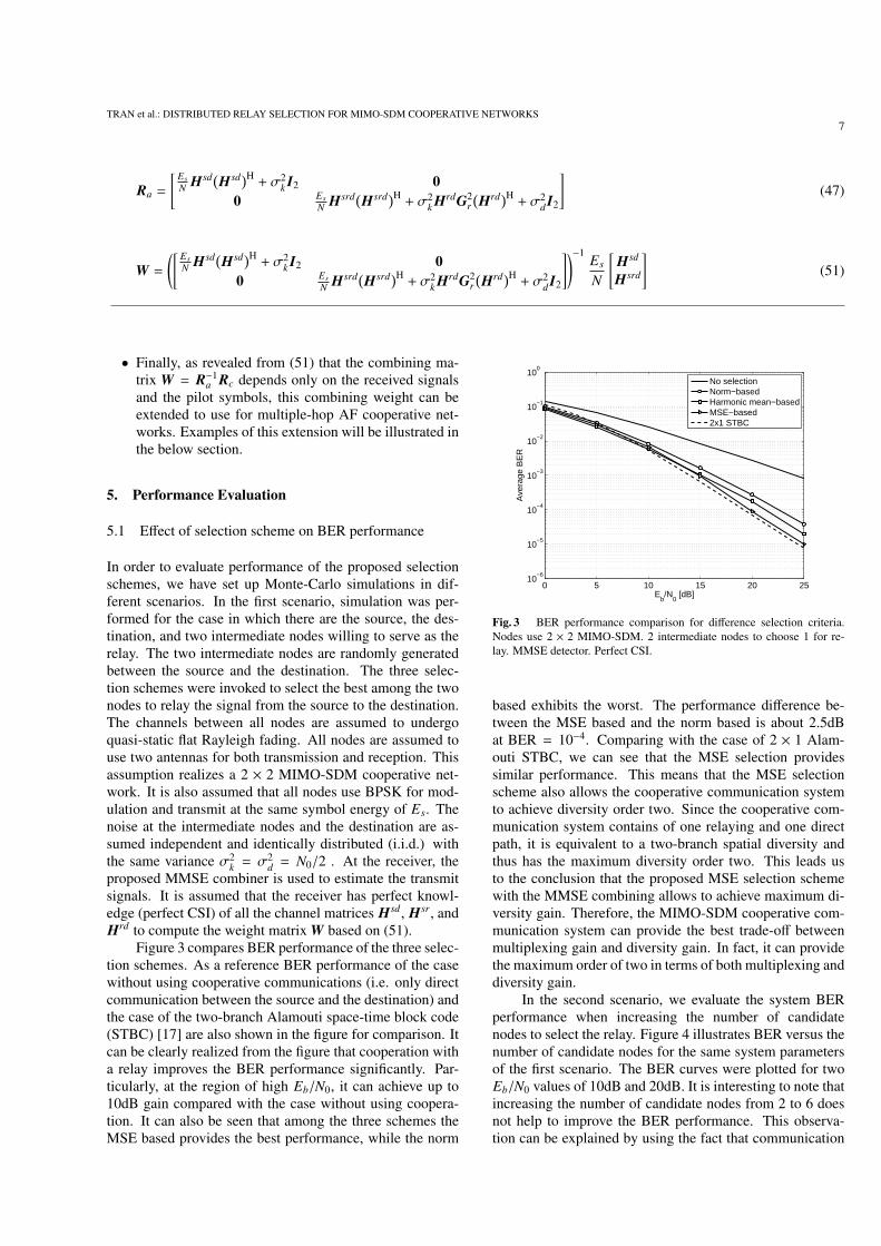
5.1 Effect of selection scheme on BER performance
In order to evaluate performance of the proposed selectionschemes, we have set up Monte-Carlo simulations in dif-ferent scenarios. In the first scenario, simulation was per-formed for the case in which there are the source, the des-tination, and two intermediate nodes willing to serve as therelay. The two intermediate nodes are randomly generatedbetween the source and the destination. The three selec-tion schemes were invoked to select the best among the twonodes to relay the signal from the source to the destination.The channels between all nodes are assumed to undergoquasi-static flat Rayleigh fading. All nodes are assumed touse two antennas for both transmission and reception. Thisassumption realizes a 2 × 2 MIMO-SDM cooperative net-work. It is also assumed that all nodes use BPSK for mod-ulation and transmit at the same symbol energy of Es. Thenoise at the intermediate nodes and the destination are as-sumed independent and identically distributed (i.i.d.) withthe same variance σ2
k = σ2d = N0/2 . At the receiver, the
proposed MMSE combiner is used to estimate the transmitsignals. It is assumed that the receiver has perfect knowl-edge (perfect CSI) of all the channel matrices Hsd, Hsr, andHrd to compute the weight matrix W based on (51).
Figure 3 compares BER performance of the three selec-tion schemes. As a reference BER performance of the casewithout using cooperative communications (i.e. only directcommunication between the source and the destination) andthe case of the two-branch Alamouti space-time block code(STBC) [17] are also shown in the figure for comparison. Itcan be clearly realized from the figure that cooperation witha relay improves the BER performance significantly. Par-ticularly, at the region of high Eb/N0, it can achieve up to10dB gain compared with the case without using coopera-tion. It can also be seen that among the three schemes theMSE based provides the best performance, while the norm
0 5 10 15 20 2510
−6
10−5
10−4
10−3
10−2
10−1
100
Eb/N
0 [dB]
Ave
rage
BE
R
No selectionNorm−basedHarmonic mean−basedMSE−based2x1 STBC
Fig. 3 BER performance comparison for difference selection criteria.Nodes use 2 × 2 MIMO-SDM. 2 intermediate nodes to choose 1 for re-lay. MMSE detector. Perfect CSI.
based exhibits the worst. The performance difference be-tween the MSE based and the norm based is about 2.5dBat BER = 10−4. Comparing with the case of 2 × 1 Alam-outi STBC, we can see that the MSE selection providessimilar performance. This means that the MSE selectionscheme also allows the cooperative communication systemto achieve diversity order two. Since the cooperative com-munication system contains of one relaying and one directpath, it is equivalent to a two-branch spatial diversity andthus has the maximum diversity order two. This leads usto the conclusion that the proposed MSE selection schemewith the MMSE combining allows to achieve maximum di-versity gain. Therefore, the MIMO-SDM cooperative com-munication system can provide the best trade-off betweenmultiplexing gain and diversity gain. In fact, it can providethe maximum order of two in terms of both multiplexing anddiversity gain.
In the second scenario, we evaluate the system BERperformance when increasing the number of candidatenodes to select the relay. Figure 4 illustrates BER versus thenumber of candidate nodes for the same system parametersof the first scenario. The BER curves were plotted for twoEb/N0 values of 10dB and 20dB. It is interesting to note thatincreasing the number of candidate nodes from 2 to 6 doesnot help to improve the BER performance. This observa-tion can be explained by using the fact that communication

8IEICE TRANS. COMMUN., VOL.Exx–??, NO.xx XXXX 200x
2 3 4 5 610
−6
10−5
10−4
10−3
10−2
10−1
100
Number of candidate nodes
Ave
rage
BE
R
Norm−based selection, Eb/No=10dBHarmonic−based selection, EbNo=10dBMSE−based selection, Eb/No=10dBNorm−based selection, Eb/No=20dBHarmonic−based selection, EbNo=20dBMSE−based selection, Eb/No=20dB
Fig. 4 BER performance versus number of candidate nodes. Nodes use2 × 2 MIMO-SDM. Perfect CSI.
via the relaying path is done using a 2 × 2 MIMO-SDMand thus there always exits interference between the twotransmit streams. Therefore, selecting a better relay froma larger group of intermediate nodes helps to improve signalenergy for one stream but in contrast also increases interfer-ence level to the other. In order to clarify this explanation letus consider the signal to interference plus noise ratio (SINR)at the input of the detector. Without loss of generality, as-sume that the MMSE detector needs to estimate s1 under thepresence of s2. As explained above this is done by combin-ing the signals from the direct and relaying path. Denotethe average power of s1 via the direct and relaying path asPd
1 and Pr1, repectively. Similarly, let Pd
2 and Pr2 be the av-
erage power of s2, and Pz the noise power at the receiver.The SINR1 associated with s1 at the input of the detector isgiven by
SINR1 =Pd
1 + Pr1
Pd2 + Pr
2 + Pz. (58)
Now assume that we can select a better relay. This meansthat we will have large values of Pr
1 and Pr2. Since the signal
power is much larger than the noise power, it can be real-ized from (58) that the SINR1 remains almost unchanged.Since BER is a function of the input SINR, it is clear thatthe BER performance is not improved significantly. Conse-quently, the overall BER performance is not benefited fromincreasing the candidate selection group size as opposed tothe case of the conventional single-antenna relay coopera-tive networks. This effect is similar to the case of increasingthe number of antennas in the MIMO-SDM systems. For ex-ample, a 4 × 4 MIMO-SDM system does improve the BERperformance compared with a 2 × 2 system, but only dou-bles multiplexing gain. The difference in BER performancebetween the three selection schemes is also observed fromthe figure at Eb/N0 = 20dB. It is also noted from the fig-ure that the MSE selection exhibits slightly fluctuated BERat Eb/N0 = 20dB when changing the number of candidatenodes.
0 5 10 15 2010
−3
10−2
10−1
100
Eb/N
0
Ave
rage
BE
R
Perfect CSIEstimated weight matrix: 16bitsEstimated weight matrix: 8bits
Fig. 5 BER performance of the MMSE combiner for different pilotlengths.
5.2 Effect of weight matrix estimation error on BER per-formance
In the next experiment, we evaluate performance of theMMSE combiner using the estimated weight matrix basedon Ra = E
{yyH
}, and Rc = E
{ypH
}for the case the train-
ing vector p contains 16 bit and 8 bit pilot sequence, re-spectively. In the simulations, each transmit stream containsa pilot bit sequence p(n) which is randomly generated andmodulated using BPSK. In this simulation scenario we as-sume that there is only one candidate node to serve as therelay. This assumption aims to ignore the effect of the selec-tion schemes on the combiner performance. Figure 5 showsthe BER performance of the MMSE combiner for the threecases: 8 bit, 16 bit pilot and perfect CSI. It is clear thatthe proposed MMSE combiner achieves BER performanceclose to the ideal case (perfect CSI) when the length of thepilot sequence equals 16 symbols. For the case the trainingsequence contains 8 symbols, the BER performance reducesby 3dB. The choice of 16 symbol pilot sequence is suitablewith the long training field (LTF) of the IEEE 802.11n stan-dards [15],[16]. Therefore, the proposed MMSE combinercan be applied to the wireless broadband systems using theIEEE 802.11n or similar standards. It is worth noting thatthe IEEE 802.11n standard uses the multicarrier orthogo-nal frequency division multiplexing (OFDM) rather than thesingle carrier transmission. However, under the assumptionthat the channel delay spread is smaller than the cyclic pre-fix length, the proposed combining scheme can be easily ap-plied to the case of MIMO-OFDM on the subcarrier basis.
In the next simulation, we prove the third property ofthe weight matrix decomposability, i.e. extension of thecombiner to the case of the AF multiple-hop cooperativesystem. The number of relaying hops is increased to demon-strate the capability of our proposed combiner. The train-ing sequence has 16 pilot bits. Figure 6 illustrates the BER

TRAN et al.: DISTRIBUTED RELAY SELECTION FOR MIMO-SDM COOPERATIVE NETWORKS9
0 5 10 15 2010
−3
10−2
10−1
100
Eb/N
0
Ave
rage
BE
R
2−hop relaying3−hop relaying4−hop relaying
Fig. 6 BER performance vs. number of relaying hops.
performance obtained for three cases: 2 hop, 3 hop and 4hop relaying. It can be seen clearly from the figure that theproposed MMSE combiner can work well for the case withmultiple hop relaying without decreasing performance.
5.3 Performance versus efficiency
In Sect. 5.1 we have seen that the cooperative communica-tion using the three relay selection schemes outperforms theconventional transmission scheme significantly. It is clearthat this improvement is achieved under the fact that the co-operative communication utilizes two time slots for trans-mission to achieve the diversity order two. However, thisimprovement would lead to the reduction in transmissionefficiency. By using two time slots this means that the trans-mission efficiency is reduced to a half. In addition, the co-operative communication also utilizes another time period(Phase 1) for relay selection. This would further decreasethe transmission efficiency. The length of this period is notfixed but mainly dependent on the number of nodes and thedistance between network nodes as well. As a result, theuse of the cooperative communication is recommended forthe case which is possible to sacrifice the transmission effi-ciency for the improvement in the BER performance.
6. Conclusions
In this paper, we have proposed three relay selectionschemmes and an MMSE combiner for MIMO-SDM coop-erative communications. The proposed MSE based selec-tion scheme was shown to exhibit better BER performancethan the other norm based and the channel harmonic meanbased. It was also shown that in the MIMO-SDM coop-erative networks increasing the number of candidate nodesdoes not help to improve the BER performance as opposedto the case of the conventional single-antenna relay system.The proposed MMSE combiner was demonstrated to be de-composed into separate combiners for the direct and the
relaying path, which facilitates its implementation in hard-ware. The proposed implementation of the combiner basedon 16 bit pilot transmission exhibits similar performancewith the case of perfect CSI and is easy to integrate into theIEEE802.11n standard. Finally, the proposed MSE basedselection scheme together with the MMSE combiner wasdemonstrated to achieve full diversity of order two. There-fore, the proposed cooperative communication system willachieve both maximum multiplexing and diversity gain.
Acknowledgement
This work is supported by National Foundation for Scienceand Technology Development (Nafosted) under the projectnumber 102.99.34.09.
References
[1] G. J. Foschini and M. J. Gans, “On Limits of Wireless Communi-cations in a Fading Environment When Using Multiple Antennas,”Wireless Personal Communications, vol. 6, no. 3, p. 311–335, March1998.
[2] P. Wolniansky, G. J. Foschini, G. D. Golden, and R. A. Valen-zuela, “V-BLAST: an Architecture for Realizing Very High DataRates Over the Rich-Scattering wireless channel,” Proc. The URSIInternational Symposium on Signals, Systems, and Electronics, Italy,September 1998.
[3] R. Pabst et al., “Relay-Based Deployment Concepts for Wireless andMobile Broadband Cellular Radio”, IEEE Communications Maga-zine, vol.42, no. 9, pp. 80–89, December 2004.
[4] W. Guan, S. Liu, H. Luo and W. Chen, “Linear relaying scheme forMIMO relay system with QoS requirements,” IEEE Signal Process-ing Letters, vol. 15, pp. 697–700, December 2010.
[5] M. Ding, S. Liu, H. Luo and W. Chen, “MMSE Based Greedy An-tenna Selection Scheme for AF MIMO Relay Systems,”, IEEE Sig-nal Processing Letters, vol. 17, no. 5, pp. 433 - 436, May 2010.
[6] W. Zhang and K. B. Letaief, Opportunistic Relaying for Dual-HopWireless MIMO Channels, Proc. IEEE Global TelecommunicationsConference, 2008.
[7] A. Bletsas et al., “A Simple Cooperative Diversity Method Based onNetwork Path Selection,” IEEE Journal on Selected Areas in Com-munications, vol. 24, no. 3, March 2006.
[8] H. Adam, C. Bettstetter, S. M. Senouci, Adaptive Relay Selection inCooperative Wireless Networks, The 19th IEEE International Sym-posium on In Personal Personal, Indoor and Mobile Radio Commu-nications (PIMRC08), 2008, Cannes, France.
[9] C. K. Lo, S. Vishwanath and R. W.Heat, Relay Subset Selectionin Wireless Networks Using Partial Decode-and-Forward Transmis-sion,” IEEE Transactions on Vehicular Technology, vol. 58, no. 2,pp. 692-704, February 2009.
[10] K. J. Ray Liu, Cooperative communications and networking, Cam-bridge University Press, 2009.
[11] A. S. Ibrahim, A. K. Sadek, S. Weifeng, and K.J.R. Liu, Cooperativecommunications with relay-selection: when to cooperate and whomto cooperate with? IEEE Trans. on Wireless Communications, vol. 7,no. 7, pp. 2814–2827, July 2008.
[12] R. Madan,N. Mehta, A. Molisch, and J. Zhang, “Energy-EfficientCooperative Relaying over Fading Channels with Simple Relay Se-lection,” IEEE Trans. on Wireless Communications, vol. 7, no. 8, pp.3013–3025, August 2008.
[13] Y. Jing, and H. Jafarkhani, “Single and multiple relay selectionschemes and their achievable diversity orders,” IEEE Trans. on Wire-less Communications, vol. 8, no. 3, pp. 1414 - 1423, March 2009.
[14] T. T. Bui, X. N. Tran, and T. Fujino, MSE based antenna selection

10IEICE TRANS. COMMUN., VOL.Exx–??, NO.xx XXXX 200x
for MIMO-SDM systems, Proc. The 2009 International Conferenceon Advanced Technologies for Communications, Oct. 2009, pp. 108–112.
[15] R. V. Nee et al., The 802.11n MIMO-OFDM Standard forWirelessLAN and Beyond, Wireless Personal Communications, vol. 37, pp.4459-6453, 2006.
[16] T. Aoki, Y. Egashira, and D. Takeda, Preamble strucucture of IEEE802.11n wireless LAN system, IEICE Transactions on Communica-tions, vol. E92-B, no. 10, pp. 3219-3227, Ocbober 2009.
[17] S. M. Alamouti, “A simple transmit diversity technique for wirelesscommunications”, IEEE J. Select. Areas in Commun., vol. 16, no. 8,pp. 1451–1458, October 1998.
Xuan Nam Tran is currently an asso-ciate professor at Department of Communica-tions Engineering at Le Quy Don Technical Uni-versity Vietnam. He received his master ofengineering (ME) in telecommunications engi-neering from University of Technology Sydney,Australia in 1998, and doctor of engineering inelectronic engineering from The University ofElectro-Communications, Japan in 2003. FromNovember 2003 to March 2006 he was a re-search associate at the Information and Commu-
nication Systems Group, Department of Information and CommunicationEngineering, The University of Electro-Communications, Tokyo, Japan.Dr. Tran’s research interests are in the areas of adaptive antennas, space-time processing, space-time coding and MIMO systems. Dr. Tran is arecipient of the 2003 IEEE AP-S Japan Chapter Young Engineer Award.He is a member of IEEE, IEICE, and the Radio-Electronics Association ofVietnam.
Vinh Hanh Nguyen Hanh Vinh Nguyen wasborn in 1972 in Hanoi, Vietnam. He receivedis bachelor degree in Radio-Electronics from LeQuy Don Technical University in 1996 and mas-ter degree in signal processing from Hanoi Uni-versity of Technology in 2003. He is currentlyworking toward his PhD degree in electronic en-gineering at Le Quy Don Technical University.
Thanh Tam Bui Thanh Tam Bui was bornin Ha Tay, Vietnam. She obtained her bache-lor degree in radio-electronics from Le Quy DonTechnical University. Her research interests arein the area of signal processing and biomedicalengineering.
The Cuong Dinh The Cuong Dinh wasborn in Hanoi, Vietnam, in 1963. He receivedthe B.Es. from Hanoi University of Technologyin 1986, the M.Es. and D.E. from the Univer-sity of Electro-Communication, Tokyo, Japan,respectively, in 1996 and 1999. He is an Asso-ciated Professor in Le Quy Don Technical Uni-versity, Hanoi, Vietnam. His main interests areon channel coding theory and its application.
Yoshio Karasawa received the B.E. de-gree from Yamanashi University, Japan, in 1973and the M.S. and Dr. Eng. degrees from Ky-oto University, Japan, in 1977 and 1992, respec-tively. In 1977, he joined KDD R&D Labs.,Tokyo, Japan. From July 1993 to July 1997,he was a Department Head of ATR Optical andRadio Communications Res. Labs. (19931996)and ATR Adaptive Communications Res. Labs.(19961997), both in Kyoto, Japan. From 1997to 1999, he was a Senior Project Manager of
KDD R&D Labs. Currently he is a professor of The University ofElectro-Communications where he simultaneously worked as the directorof the Advanced Wireless Communication research Center (AWCC) from20052007. He was also a visiting professor of Osaka University, Osaka,Japan (20002001). Since 1977, he has been engaged in studies on wavepropagation and radio communication antennas, particularly on theoreticalanalysis and measurements for wave-propagation phenomena, such as mul-tipath fading in mobile radio systems, tropospheric and ionospheric scin-tillation,and rain attenuation. His recent interests are in frontier regionsbridging “wave propagation” and “digital transmission characteristics” inwideband mobile radio systems and digital and optical signal processingantennas.Dr. Karasawa received the Young Engineers Award from the IECE of Japanin 1983, the Meritorious Award on Radio from the Association of RadioIndustries and Businesses (ARIB, Japan) in 1998, Research Award fromICF in 2006, and two Paper Awards from IEICE in 2006. He is a fellow ofthe IEICE and IEEE. He is also a member of URSI and SICE (Japan).