102 lathe manual - automotive equipment service co. · drum capacity 6” t o 28” * 152.4mm t o...
TRANSCRIPT

102
Single-Pass
Combo
Lathe
Instruction Manual and Parts List
Kwik-Way Products Inc. 800-553-5953 Copyright 2005 All Rights Reserved
500 5 7
th
Street, Marion, IA 52302 USA Equipment specifications, options and accessories subject to change without notice.


102 Single-Pass Combination Brake Lathe
521 WARRANTY
Brake Lathes · Tire Changers ·
Wheel Balancers
Kwik-Way Products Inc. (Kwik-Way) provides a limited 521 Warranty on products when purchased in a new and
unused condition to be free from defective material or workmanship from date of purchase as per the following:
Product
Category
BENCH MODEL
LATHES
ON-CAR-LATHES
PASSENGER CAR
TIRE CHANGERS
WHEEL
BALANCERS
TRUCK LATHES
AND
TIRE CHANGERS
5 Years
Spindle, spindle
bearing and housing
Cast iron
components,
excluding guide rods
Transmission
Frame, welding
construction
N/A
2 Years
All other mechanical
parts
All other mechanical
parts
All other mechanical
parts
All other mechanical
parts
N/A
1 Year
Motor, electronic
components and
labor
Motor, electronic
components and
labor
Motor, electronic
components and
labor
Motor, electronic
components and
labor
Machine, components
and labor
Kwik-Way will repair and/or replace, free of charge (FOB factory) all such defective parts, only when
returned to factory with shipping charges prepaid. This warranty does not cover parts and supplies (nylon
inserts, nylon mount-demount heads, breaker blade covers, and mount-demount covers) consumed in
normal operation of the machine.
Kwik-Way disclaims all other warranties, expressed or implied, as to the quality of any goods, including
implied warranties of MERCHANTABILITY and FITNESS FOR PARTICULAR PURPOSES. UNDER NO
CIRCUMSTANCES WHATSOEVER, SHALL Kwik-Way BE LIABLE FOR ANY INCIDENTAL OR
CONSEQUENTIAL DAMAGES, WHETHER BASED ON LOST GOODWILL, LOST RESALE PROFITS,
WORK STOPPAGE, IMPAIRMENT OF OTHER GOODS OR ARISING OUT OF BREACH OF ANY
EXPRESS OR IMPLIED WARRANTY, BREACH OF CONTRACT, NEGLIGENCE OR OTHERWISE,
EXCEPT ONLY IN THE CASE OF PERSONAL INJURY.
Because of Kwik-Way’s constant program of product improvement, specifications are subject to change
without notice.
This warranty does not apply to a product that has been purchased in used condition, that has failed due
to improper installation, repairs, service or that has sustained damage caused by accident, improper use
or shipment.
Model #: Serial #:
Purchase Date:
For further information or questions, please contact Kwik-Way Products Inc at 800/553-5953 or
319/377-9421, fax 319/377-9101, email [email protected]
800-553-5953 1
Kwik-Way Products Inc. 500 57
th
Street, Marion, IA 52302 USA
Copyright 2005 All Rights Reserved
Equipment specifications, options and accessories subject to change without notice.


102 Single-Pass Combination Brake Lathe
RECEIVING SHIPMENT
Upon taking delivery of your machine, carefully inspect the assembly before removing
the crating and packing materials.
If evidence of damage exists, contact the shipper and Kwik-Way Products Inc.
immediately. Although Kwik-Way Products Inc. is not responsible for damage incurred
during transit, you will be provided assistance in preparation and filing of any necessary
claims.
CAREFULLY READ THIS MANUAL BEFORE ATTEMPTING TO SETUP OR
OPERATE THIS MACHINE.
IMPORTANT NOTE
Always have your serial number ready when communicating with Kwik-Way Products
Inc. regarding parts or service.
Keep this manual in a safe place.
Date Received:
Serial Number:
(Serial Number location: Upper left corner at rear of unit)
800-553-5953 2
Kwik-Way Products Inc. 500 57
th
Street, Marion, IA 52302 USA
Copyright 2005 All Rights Reserved
Equipment specifications, options and accessories subject to change without notice.
102 Single-Pass Combination Brake Lathe
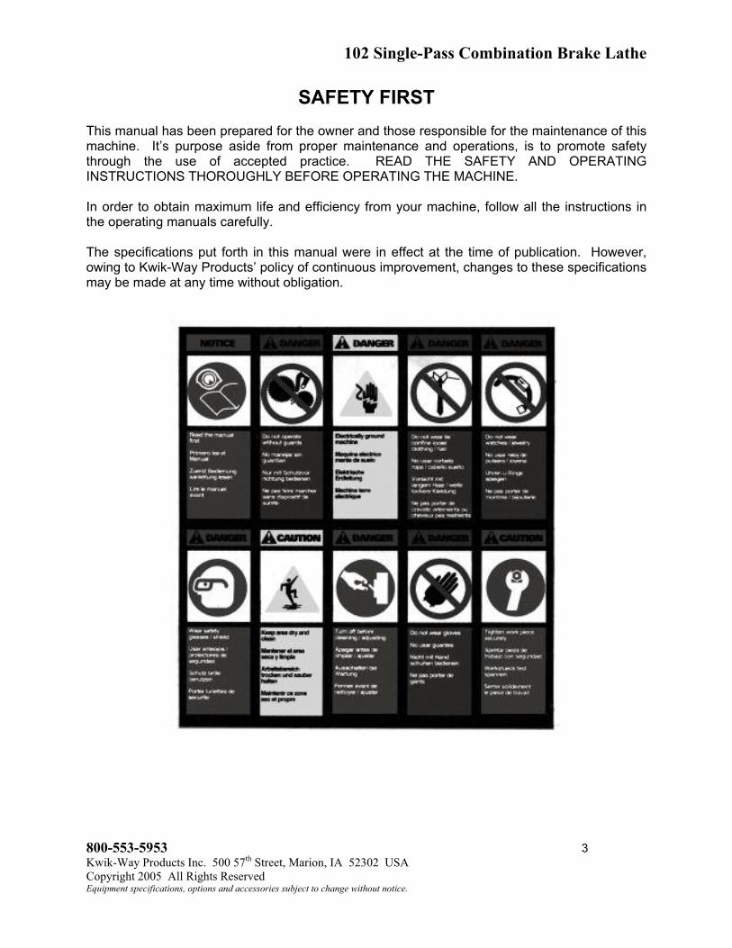
SAFETY FIRST
This manual has been prepared for the owner and those responsible for the maintenance of this
machine. It’s purpose aside from proper maintenance and operations, is to promote safety
through the use of accepted practice. READ THE SAFETY AND OPERATING
INSTRUCTIONS THOROUGHLY BEFORE OPERATING THE MACHINE.
In order to obtain maximum life and efficiency from your machine, follow all the instructions in
the operating manuals carefully.
The specifications put forth in this manual were in effect at the time of publication. However,
owing to Kwik-Way Products’ policy of continuous improvement, changes to these specifications
may be made at any time without obligation.
800-553-5953 3
Kwik-Way Products Inc. 500 57
th
Street, Marion, IA 52302 USA
Copyright 2005 All Rights Reserved
Equipment specifications, options and accessories subject to change without notice.

102 Single-Pass Combination Brake Lathe
SAFETY INSTRUCTIONS
1. Read, understand and follow the safety and operating instructions found in this manual.
Know the limitations and hazards associated with operating the machine.
2. Eye Safety: Wear an approved safety face shield, goggles or safety glasses to protect eyes
when operating the machine.
3. Grounding the Machine: Machines equipped with three prong grounding plugs are so equipped
for your protection against shock hazards and should be plugged directly into a properly
grounded three-prong receptacle in accordance with national electrical codes and local codes
and ordinances. A grounding adapter may be used. If one is used, the green lead should be
securely connected to a suitable electrical ground such as a ground wire system. Do not cut off
the grounding prong or use an adapter with the grounding prong removed.
4. Work Area: Keep the floor around the machine clean and free of tools, tooling, stock scrap and
other foreign material and oil, grease or coolant to minimize the danger of tripping or slipping.
Kwik-Way recommends the use of anti-skid floor strips on the floor area where the operator
normally stands and that each machine's work area be marked off. Make certain the work area
is well lighted and ventilated. Provide for adequate workspace around the machine.
5. Guards: Keep all machine guards in place at all times when machine is in use.
6. Do Not Overreach: Maintain a balanced stance and keep your body under control at all times.
7. Hand Safety: NEVER wear gloves while operating this machine.
8. Machine Capacity: Do not attempt to use the machine beyond its stated capacity or operations.
This type of use will reduce the productive life of the machine and could cause the breakage of
parts, which could result in personal injury.
9. Avoid Accidental Starting: Make certain the main switch is in the OFF position before connecting
power to the machine.
10. Careless Acts: Give the work you are doing your undivided attention. Looking around, carrying
on a conversation and horseplay are careless acts that can result in serious injury.
11. Job Completion: If the operation is complete, the machine should be emptied and the work area
cleaned.
12. Disconnect All Power and Air to Machine before performing any service or maintenance.
13. Replacement Parts: Use only Kwik-Way replacement parts and accessories; otherwise,
warranty will be null and void.
14. Misuse: Do not use the machine for other than its intended use. If used for other purposes,
Kwik-Way Products Inc. disclaims any real or implied warranty and holds itself harmless for any
injury or loss that may result from such use.
800-553-5953 4
Kwik-Way Products Inc. 500 57
th
Street, Marion, IA 52302 USA
Copyright 2005 All Rights Reserved
Equipment specifications, options and accessories subject to change without notice.

102 Single-Pass Combination Brake Lathe
TECHNICAL SPECIFICATIONS
Disc Capacity 6” to 18” * 152.44mm to 457.2mm
Face Width (max) 3 ½” 88.9mm
Thickness (max) 2” 50mm
Drum Capacity 6” to 28” * 152.4mm to 711.2mm
Depth of Cut 7” 177.8mm
Spindle Speed 105RPM
Disc Feed per Spindle Rev. .003” .0762mm
(3 minute per 1” disc travel)
Drum Feed per Spindle Rev .005” .127mm
(2 min per 1” drum travel)
Feed Motor H.P. 1/100 H.P.
Spindle Motor H.P. ½ H.P.
Net Weight 370 lbs. 167.8kg
Shipping Weight 410 lbs. 186kg
With Stand 495 lbs 224.5kg
* Will require 102-1069-00 Optional Arbor Set for drums over 14” and rotors over 16” as well as
109-1092-23 carbide bit inserts (10 pack).
800-553-5953 5
Kwik-Way Products Inc. 500 57
th
Street, Marion, IA 52302 USA
Copyright 2005 All Rights Reserved
Equipment specifications, options and accessories subject to change without notice.

102 Single-Pass Combination Brake Lathe
ILLUSTRATION OF MACHINE
FIGURE 1
Main Power Switch (1): A two-position rocker switch. When the left side is depressed, all
power to the motors is shut off. When the right side of the switch is depressed, the spindle
motor starts, the spindle begins to rotate and power is supplied to the Disc/Drum Switch.
Disc/Drum Switch (2): A three-position switch. When the left side of the switch is depressed,
power is supplied to the disc feed motor. When the right side of the switch is depressed, power
is supplied to the drum feed motor. When the switch is in the neutral position (centered), power
to both motors is OFF.
Disc Safety Switch (3): A two-position toggle switch that serves as an automatic shut-off of the
disc feed motor. In order for power to the supplied to the disc feed motor, the toggle must be
pointed away from the handwheel.
Drum Safety Switch (4): A two-position toggle switch that serves as an automatic shut-off of
the drum feed motor. In order for power to be supplied to the drum feed motor, the toggle must
be pointing to the left.
Feed Screw Handwheel (5): This handwheel is used to move the feed/slide plate either left or
right as you face the front of the machine.
Cross Slide Handwheel (6): This handwheel is sued to move the feed/slide plate either in or
out as you face the front of the machine.
800-553-5953 6
Kwik-Way Products Inc. 500 57
th
Street, Marion, IA 52302 USA
FIGURE 1
Copyright 2005 All Rights Reserved
Equipment specifications, options and accessories subject to change without notice.

102 Single-Pass Combination Brake Lathe
INSTALLATION
WARNING: Never attempt to lift this machine using the arbor or any handwheel.
1. Remove the button head cap screw from the top of the spindle housing and install the 3/8-
16 lifting eye bolt (found in the accessory package) in its place. Be sure the eye bolt is
down tight.
2. Using the eyebolt as a lifting point, place the machine in its predetermined location and
secure using the three (3) mounting lugs on the machine base. Figure 1
3. Thoroughly clean the machine, using a soft cloth and an approved solvent, to remove any
preservative coating.
WARNING: Do not use lacquer thinner.
4. Be sure all switches are in the OFF position.
WARNING: Do not attempt to test, set-up or operate this machine until you are completely
familiar with the functions of all the controls and switches.
DISC TURNING ATTACHMENT
This attachment can be mounted in any one of six combinations depending on the diameter of
the disc. The maximum in any positions is 4”. Figure 2
1. Select the appropriate threaded hole in the feed/slide plate and screw one end of the clamp
stud into it.
2. Place one of the slotted holes of the disc plate over the stud. Add the 1 ½ high spacer and
the ½” SAE washer. Secure using the clamp handle.
NOTE: Final location of the disc attachment will be made after the disc has been installed.
800-553-5953 7
Kwik-Way Products Inc. 500 57
th
Street, Marion, IA 52302 USA
FIGURE 2
Copyright 2005 All Rights Reserved
Equipment specifications, options and accessories subject to change without notice.
102 Single-Pass Combination Brake Lathe
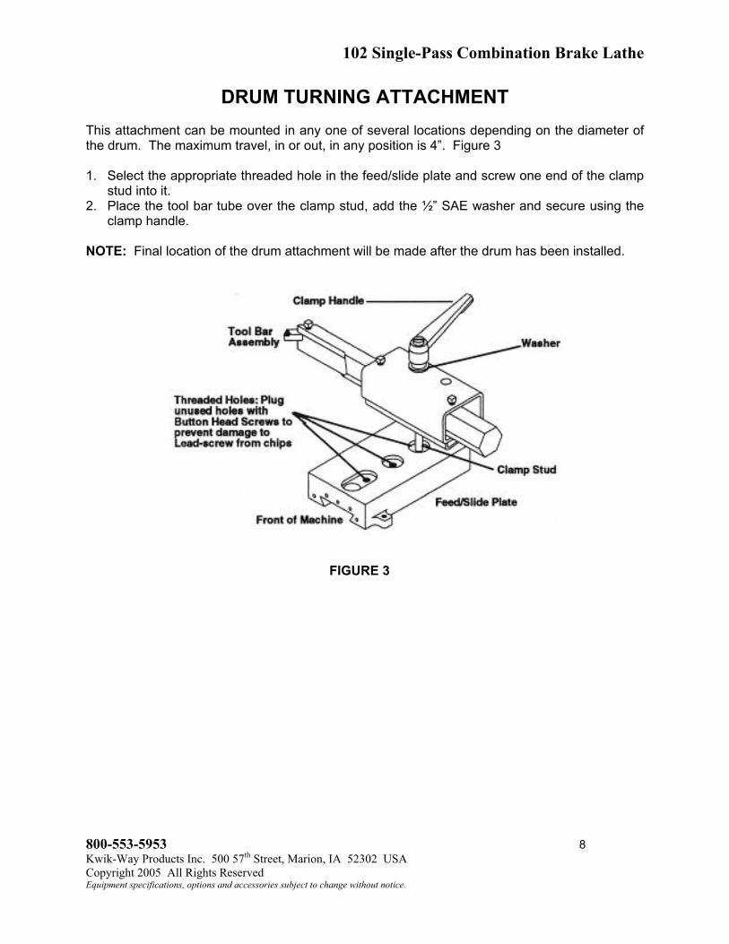
DRUM TURNING ATTACHMENT
This attachment can be mounted in any one of several locations depending on the diameter of
the drum. The maximum travel, in or out, in any position is 4”. Figure 3
1. Select the appropriate threaded hole in the feed/slide plate and screw one end of the clamp
stud into it.
2. Place the tool bar tube over the clamp stud, add the ½” SAE washer and secure using the
clamp handle.
NOTE: Final location of the drum attachment will be made after the drum has been installed.
FIGURE 3
800-553-5953 8
Kwik-Way Products Inc. 500 57
th
Street, Marion, IA 52302 USA
Copyright 2005 All Rights Reserved
Equipment specifications, options and accessories subject to change without notice.

102 Single-Pass Combination Brake Lathe
ARBOR ATTACHMENT
The standard arbor, like the optional arbors, mounts quickly to the spindle receptacle using a
threaded draw bar and handwheel. Figure 4
1. Insert the arbor, threaded hole first, into the spindle receptacle at the left end of the spindle
housing (be sure the drive pin on the receptacle and the hole in the face of the arbor flange
are in alignment).
NOTE: Make certain mating surfaces are clean and free of nicks and gouges.
WARNING: Never loosen or attempt to remove arbor with a disc or drum mounted.
2. Turn the spindle lock-up handwheel until the arbor is drawn up tight – the arbor is now ready
to accept the mounting components and the work piece.
NOTE: To remove the arbor, give the lock-up handwheel a quick counter-clockwise turn to
loosen. Continued counter-clockwise rotation frees the bar from the arbor, allowing the arbor to
be pulled clear of the receptacle.
FIGURE 4
800-553-5953 9
Kwik-Way Products Inc. 500 57
th
Street, Marion, IA 52302 USA
Copyright 2005 All Rights Reserved
Equipment specifications, options and accessories subject to change without notice.

102 Single-Pass Combination Brake Lathe
DISC TURNING SET-UP INSTRUCTIONS
Install the disc turning attachment and the arbor as previously described. Mount the disc onto
the arbor per the appropriate illustration.
HUB TYPE DISC (With Race In Place)
FIGURE 5
HUBLESS DISC
FIGURE 6
800-553-5953 10
Kwik-Way Products Inc. 500 57
th
Street, Marion, IA 52302 USA
Copyright 2005 All Rights Reserved
Equipment specifications, options and accessories subject to change without notice.

102 Single-Pass Combination Brake Lathe
HUBLESS “BONNET TYPE” DISC
800-553-5953 11
Kwik-Way Products Inc. 500 57
th
Street, Marion, IA 52302 USA
FIGURE 7
DISC TURNING OPERATING INSTRUCTIONS
1. Install the dampening band around the outside edge of the disc before installing the disc on
the arbor.
2. Once the set-up for the disc is complete and tightened in place, final positioning of the
turning attachment can be made.
a. Turn the cross side handwheel counter-clockwise until the tool bed is as close to the
spindle housing as possible without the bed interfering with the outside of the edge of
the disc. It may be necessary to remove the attachment and reposition the clamp stud
further out on the bed.
b. Loosen the clamp handle and slide the disc turning attachment right or left so that the
disc is centered between the tool bits. Tighten the clamp handle being sure the
attachment is square to the tool bed.
c. Check each of the tool bits to be sure they are still in serviceable condition. If not, rotate
to next point of the tool bit.
NOTE: Be sure tool bit screws are down tight.
3. Check to be sure that the disc/drum switch is in the “OFF” position and that both of the
handwheel knobs are loosened one-quarter turn.
4. Depress the right side of the main power switch, turning on the spindle motor.
5. Using the cross slide handwheel, locate the tool bits in Figure 8 (1) and loosen tool bar
clamp handle. Figure 2.
Copyright 2005 All Rights Reserved
Equipment specifications, options and accessories subject to change without notice.

102 Single-Pass Combination Brake Lathe
DISC TURNING OPERATING INSTRUCTIONS (continued)
HUB
FIGURE 8
6. Using the calibrated thumb screws, slowly feed the tool bits in until they just contact the disc
wear area (note the setting on each calibrated thumb screw). Tighten tool bar clamp
handle.
NOTE: Each mark on the calibrated thumbscrew equals approximately .002”.
7. With the disc turning, slowly rotate the cross slide handwheel clockwise until the lip is
removed and both tool bits are past the outside edge.
8. With the disc turning, rapidly rotate the cross slide handwheel counter-clockwise moving tool
bits close to the inner lip.
9. Slowly turn the cross slide handwheel counter-clockwise until enough of the inner lip is
removed to provide clearance for the pad. Figure 8(2)
10. With the spindle motor on and the disc turning, feed in each tool bit .002 to .010.
11. Depress the left side of the disc/drum switch, tighten the knob on the cross slide handwheel
and allow the auto feed to run until the tool bits clear the outside edge of the disc. Turn off
disc/drum switch and spindle motor.
12. Check both surfaces for total clean up.
13. If additional material must be removed, relocate the tool bits in Figure 8(2) and feed them in
an additional .002 to .010 and repeat step 11.
NOTE: On deeply scored discs, the side with the groove should be machined first. This
prevents tool deflection on thin rotors and minimizes the amount of stock removal necessary to
clean up.
WARNING: Never remove so much material as to reduce the thickness of the disc below the
manufacturers’ recommended minimums.
800-553-5953 12
Kwik-Way Products Inc. 500 57
th
Street, Marion, IA 52302 USA
Copyright 2005 All Rights Reserved
Equipment specifications, options and accessories subject to change without notice.
102 Single-Pass Combination Brake Lathe
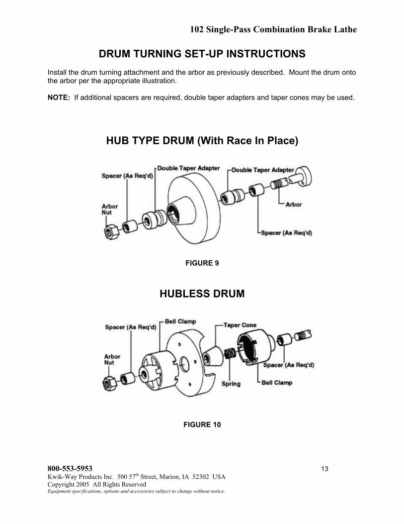
DRUM TURNING SET-UP INSTRUCTIONS
Install the drum turning attachment and the arbor as previously described. Mount the drum onto
the arbor per the appropriate illustration.
NOTE: If additional spacers are required, double taper adapters and taper cones may be used.
HUB TYPE DRUM (With Race In Place)
FIGURE 9
HUBLESS DRUM
FIGURE 10
800-553-5953 13
Kwik-Way Products Inc. 500 57
th
Street, Marion, IA 52302 USA
Copyright 2005 All Rights Reserved
Equipment specifications, options and accessories subject to change without notice.

102 Single-Pass Combination Brake Lathe
KWIK-CHUCK SET-UP INSTRUCTIONS
(Hubless Discs and Drums)
Install the disc truing attachment and the arbor as previously described. Mount the disc onto the
arbor with the Kwik-Chuck.
1. Thoroughly clean the surface of the rotor or drum that is to be mounted on the Kwik-Chuck.
2. Place the hubless rotor or drum on a clean, flat surface. Install the rotor or drum onto the
shuck by positioning the jaws into the center hole. Tighten the jaws by inserting the chuck
key into one of the key slots on the side of the chuck. Turn the key counter-clockwise, the
Kwik-Chuck will automatically center the rotor or drum. Make sure the jaws are tight.
CAUTION: Remove the chuck key before starting the brake lathe.
3. Install the correct backing plate onto the arbor with the offset facing outboard. Install the
Kwik-Chuck with the rotor or drum attached. Using the necessary spacers supplied with the
brake lathe, space out to the arbor threads. Using the arbor nut supplied with the lathe,
tighten the nut against the spacers. After tightening, turn the brake lathe on and check the
rotor or drum for run out. Correct if necessary. You are now ready to resurface the rotor or
drum.
FIGURE 12
NOTE: The Kwik-Chuck will work on any brake lathe using a 1” arbor.
800-553-5953 14
Kwik-Way Products Inc. 500 57
th
Street, Marion, IA 52302 USA
Copyright 2005 All Rights Reserved
Equipment specifications, options and accessories subject to change without notice.

102 Single-Pass Combination Brake Lathe
REMOVING CHUCK JAWS
It will be necessary to remove the chuck jaws for cleaning or when changing to the large jaws
required for truck applications. The jaws are numbered 1, 2, and 3 and it is very important that
they are installed into the corresponding numbered slot.
1. Re-install in the order of 1, 2, and 3 (counter clockwise). Figure 13
Step 1: Enter Jaw #1 in Slot #1 when scroll is in this position.
Step 2: Enter Jaw #2 in Slot #2 when scroll is in this position.
Step 3: Enter Jaw #3 in Slot #3 when scroll is in this position.
FIGURE 13
2. A slight amount of pressure may be required on each of the jaws to allow them to be
installed evenly and correctly.
Parts included with the Deluxe Kwik-Chuck:
102-0800-30 Kwik-Chuck with small jaws
102-0800-05 Standard Backing Plate: 5 ½” (140mm)
102-0800-35 Kwik-Wrench
102-0800-25 Large Jaw Set: 3 ¾” –5 ¾ (95-146mm)
102-0800-20 Large Backing Plate: 7 ¼” (184mm)
102-0800-10 Small Backing Plate: 4 ½” (114mm)
800-553-5953 15
Kwik-Way Products Inc. 500 57
th
Street, Marion, IA 52302 USA
Copyright 2005 All Rights Reserved
Equipment specifications, options and accessories subject to change without notice.
102 Single-Pass Combination Brake Lathe
DRUM TURNING OPERATING INSTRUCTIONS
1. Install the dampening band around the outside of the drum before installing the drum on the
arbor.
2. Once the set-up for the drum is complete and tightened in place, final positioning of the
turning attachment can be made.
a. Check the tool bit to be sure it is still in serviceable condition. If not, rotate to next point
of the tool bit. NOTE: Be sure tool bit screws are down tight.
b. Turn the cross side handwheel counter-clockwise until the tool bed is as close to the
spindle housing as possible. Turn the feed screw handwheel counter-clockwise until the
tool bed is as far left as possible. It may now be necessary to remove the attachment
and reposition the clamp stud further out on the bed so that the tool bit is closer to the
inside diameter of the drum.
c. Loosen the two square head set screws on top of the tool bar tube and slide the tool bar
to the left until the tool bit just contracts the inside of the drum and turn the feed screw
handwheel 3 to 4 revolutions clockwise. Tighten both set screws and the clamp handle,
being sure the tool bar is square to the tool bed.
3. Check to be sure that the disc/drum switch is in the OFF position and that both of the
handwheel knobs are loosened one-quarter turn.
4. Depress the right side of the main power switch, turning on the spindle motor.
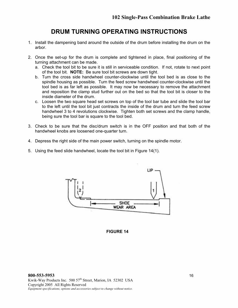
5. Using the feed slide handwheel, locate the tool bit in Figure 14(1).
FIGURE 14
800-553-5953 16
Kwik-Way Products Inc. 500 57
th
Street, Marion, IA 52302 USA
Copyright 2005 All Rights Reserved
Equipment specifications, options and accessories subject to change without notice.
102 Single-Pass Combination Brake Lathe
DRUM TURNING OPERATING INSTRUCTIONS (continued)
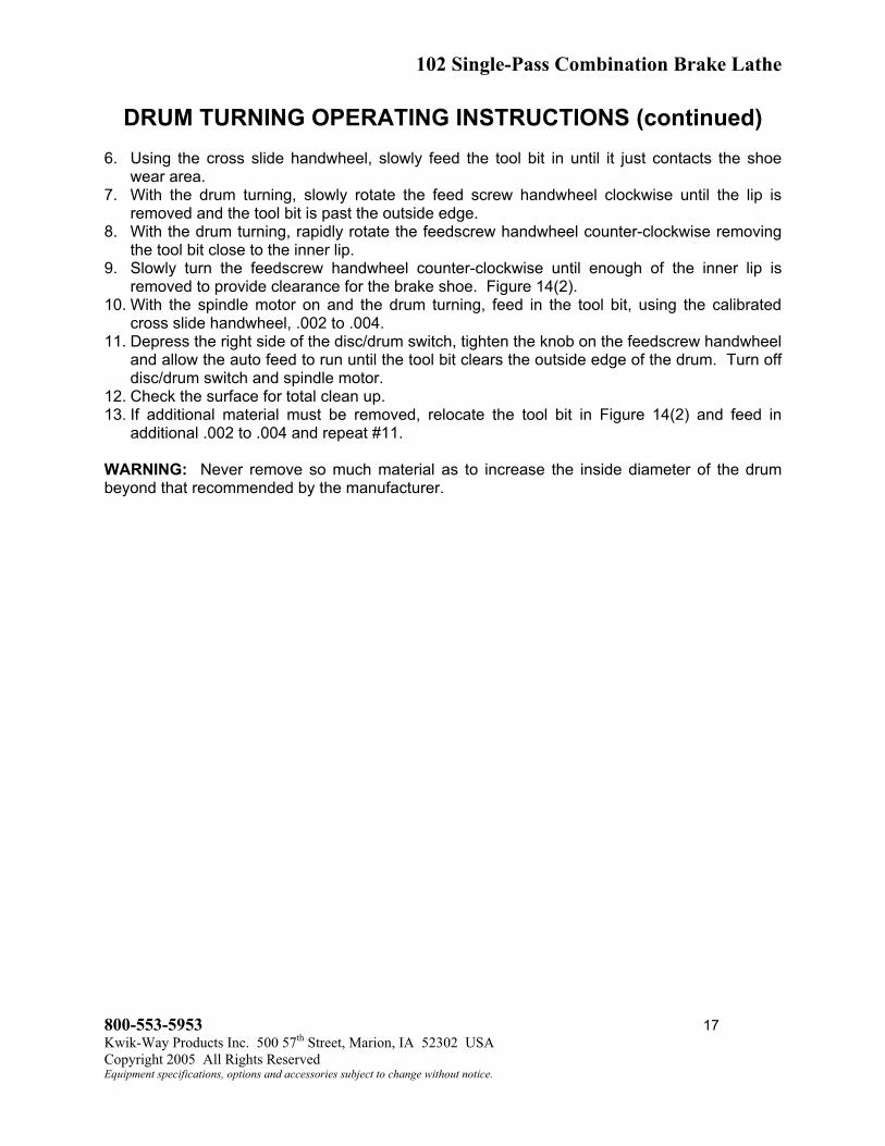
6. Using the cross slide handwheel, slowly feed the tool bit in until it just contacts the shoe
wear area.
7. With the drum turning, slowly rotate the feed screw handwheel clockwise until the lip is
removed and the tool bit is past the outside edge.
8. With the drum turning, rapidly rotate the feedscrew handwheel counter-clockwise removing
the tool bit close to the inner lip.
9. Slowly turn the feedscrew handwheel counter-clockwise until enough of the inner lip is
removed to provide clearance for the brake shoe. Figure 14(2).
10. With the spindle motor on and the drum turning, feed in the tool bit, using the calibrated
cross slide handwheel, .002 to .004.
11. Depress the right side of the disc/drum switch, tighten the knob on the feedscrew handwheel
and allow the auto feed to run until the tool bit clears the outside edge of the drum. Turn off
disc/drum switch and spindle motor.
12. Check the surface for total clean up.
13. If additional material must be removed, relocate the tool bit in Figure 14(2) and feed in
additional .002 to .004 and repeat #11.
WARNING: Never remove so much material as to increase the inside diameter of the drum
beyond that recommended by the manufacturer.
800-553-5953 17
Kwik-Way Products Inc. 500 57
th
Street, Marion, IA 52302 USA
Copyright 2005 All Rights Reserved
Equipment specifications, options and accessories subject to change without notice.

102 Single-Pass Combination Brake Lathe
OPTIONAL EQUIPMENT SETUP INSTRUCTIONS
Install the disc or drum turning attachment instructions. Mount the disc/drum onto the
appropriate arbor per the illustrations.
11/16” ARBOR (#102-1059-00): Designed to accommodate discs/drums with center holes of
less than one inch inside diameter, including those that are splined. Figure 15
NOTE: This arbor replaces the standard arbor for this application.
FIGURE 15
800-553-5953 18
Kwik-Way Products Inc. 500 57
th
Street, Marion, IA 52302 USA
Copyright 2005 All Rights Reserved
Equipment specifications, options and accessories subject to change without notice.

102 Single-Pass Combination Brake Lathe
CARE AND MAINTENANCE
Your Combination Brake is designed as a minimal maintenance product. However, some basic
maintenance will assure that it will continue to operate in a satisfactory manner.
1. Using a shop vac, remove all of the chips and dust from on and above the lathe. Do not use
air to clean off the machine.
2. Occasionally add a drop of lightweight oil directly to the threads of the feedscrew.
3. Apply a thin layer of lightweight oil to the arbor, taper cones and double radius adapters
after each use.
4. Motors and gear boxes are sealed for life and require no further lubrication.
5. Gibs are factory-adjusted and held in place with Nyloc set screws. No adjustment is
needed.
HELPFUL HINTS
1. Get acquainted with your combination lathe. We recommend that you use a scrap disc or
drum and practice before beginning an actual job. This will avoid any undue pressure or
failure while learning.
2. Always clean the surfaces that will be contacting the taper cones, double radius adapter(s)
or bell clamps(s).
3. A disc or drum with excessive run out or wobble (after having cleaned and installed
properly) indicates that it may be damaged or bent. Disc or drums with these symptoms
should be closely inspected before being put back into service.
4. If in doubt, DON’T DO IT!
800-553-5953 19
Kwik-Way Products Inc. 500 57
th
Street, Marion, IA 52302 USA
Copyright 2005 All Rights Reserved
Equipment specifications, options and accessories subject to change without notice.
102 Single-Pass Combination Brake Lathe
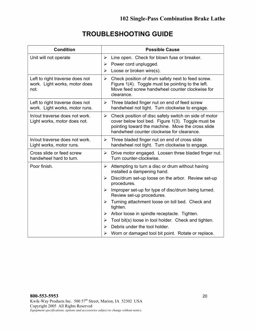
TROUBLESHOOTING GUIDE
Condition Possible Cause
Unit will not operate Line open. Check for blown fuse or breaker.
Power cord unplugged.
Loose or broken wire(s).
Left to right traverse does not
work. Light works, motor does
not.
Check position of drum safety next to feed screw.
Figure 1(4). Toggle must be pointing to the left.
Move feed screw handwheel counter clockwise for
clearance.
Left to right traverse does not
work. Light works, motor runs.
Three bladed finger nut on end of feed screw
handwheel not tight. Turn clockwise to engage.
In/out traverse does not work.
Light works, motor does not.
Check position of disc safety switch on side of motor
cover below tool bed. Figure 1(3). Toggle must be
pointing toward the machine. Move the cross slide
handwheel counter clockwise for clearance.
In/out traverse does not work.
Light works, motor runs.
Three bladed finger nut on end of cross slide
handwheel not tight. Turn clockwise to engage.
Cross slide or feed screw
handwheel hard to turn.
Drive motor engaged. Loosen three bladed finger nut.
Turn counter-clockwise.
Poor finish. Attempting to turn a disc or drum without having
installed a dampening hand.
Disc/drum set-up loose on the arbor. Review set-up
procedures.
Improper set-up for type of disc/drum being turned.
Review set-up procedures.
Turning attachment loose on toll bed. Check and
tighten.
Arbor loose in spindle receptacle. Tighten.
Tool bit(s) loose in tool holder. Check and tighten.
Debris under the tool holder.
Worn or damaged tool bit point. Rotate or replace.
800-553-5953 20
Kwik-Way Products Inc. 500 57
th
Street, Marion, IA 52302 USA
Copyright 2005 All Rights Reserved
Equipment specifications, options and accessories subject to change without notice.

102 Single-Pass Combination Brake Lathe
MAIN ASSEMBLY
800-553-5953 21
Kwik-Way Products Inc. 500 57
th
Street, Marion, IA 52302 USA
Copyright 2005 All Rights Reserved
Equipment specifications, options and accessories subject to change without notice.

102 Single-Pass Combination Brake Lathe
MAIN ASSEMBLY
ITEM PART # DESCRIPTION QTY
1 See Page 21 Spindle Assembly
2 See Page 23 Gear Assembly
3 See Page 27 Cross Feed Assembly
4 000-2602-26 Bushing, Strain Relief 2
5 102-3010-00 Base 1
6 102-1040-00 Shield. Base Protective 1
7 102-3013-00 Cover, Front 1
8 000-6644-00 Decal, Front Panel 1
9 000-6600-16 Decal, Electrical Data 1
10 000-0592-40 ¼-20 x 1 ¼ Button Head Cap Screw 2
11 000-0592-30 ¼-20 x 7/8 Button Head Cap Screw 3
12 102-3014-00 Cover, Transmission 1
13 000-6609-06 Decal, General Caution 1
14 000-6676-10 Decal, Caution Grade Level 1
800-553-5953 22
Kwik-Way Products Inc. 500 57
th
Street, Marion, IA 52302 USA
Copyright 2005 All Rights Reserved
Equipment specifications, options and accessories subject to change without notice.

102 Single-Pass Combination Brake Lathe
SPINDLE ASSEMBLY
800-553-5953 23
Kwik-Way Products Inc. 500 57
th
Street, Marion, IA 52302 USA
Copyright 2005 All Rights Reserved
Equipment specifications, options and accessories subject to change without notice.

102 Single-Pass Combination Brake Lathe
SPINDLE ASSEMBLY
ITEM PART # DESCRIPTION QTY
1 000-7204-45 Pin, Roll – 3/16 x 1 ¼ 1
2 000-1640-50 Bearing, Taper Roller – Drive End 1
3 000-1640-52 Bearing, Taper Roller – Arbor End 1
4 102-1034-02 Hand Wheel – Drawbar 1
5 102-1035-00 Drawbar 1
6 000-3306-00 Seal, Oil 2
7 000-0488-28 5/16-18 x ¾ Cup Pt. Socket Set Screw 1
8 000-7300-25 Key, Woodruff - #304 1
9 000-9200-53 Bushing, Oilite 1
10 102-1036-00 Spacer, Drawbar 1
11 102-1053-00 Arbor, 1” Diameter 1
12 102-1031-00 Spacer, Preload 1
13 102-1032-00 Spindle 1
14 102-1064-00 Arbor Nut 1
15 102-3012-00 Housing, Spindle 1
16 000-6609-35 Decal, Rotating Part 1
17 000-0700-09 Eye Bolt, Lifting 1
18 000-0591-82 3/8-16 x ½ Button Head Cap Screw 1
19 000-0167-80 5/16-18 x ¾ Socket Head Cap Screw 2
20 000-1155-33 Washer, SAE 3/8 2
21 000-0170-27 3/8-16 x 1 Socket Head Cap Screw 2
22 000-6644-30 Decal, Kwik-Way 1
800-553-5953 24
Kwik-Way Products Inc. 500 57
th
Street, Marion, IA 52302 USA
Copyright 2005 All Rights Reserved
Equipment specifications, options and accessories subject to change without notice.

102 Single-Pass Combination Brake Lathe
GEAR ASSEMBLY
800-553-5953 25
Kwik-Way Products Inc. 500 57
th
Street, Marion, IA 52302 USA
Copyright 2005 All Rights Reserved
Equipment specifications, options and accessories subject to change without notice.

102 Single-Pass Combination Brake Lathe
GEAR ASSEMBLY
ITEM PART # DESCRIPTION QTY
1 102-3010-00 Base 1
2 102-1032-00 Spindle 1
3 001-1950-00 Spindle Motor 1
4 001-1938-68 Feed Gear Motor 1
5 000-7300-25 Key 2
6 102-1030-00 Sprocket, Spindle 1
7 000-1840-30 Lockwasher 1
8 000-1840-32 Nut, Bearing 1
9 003-0072-22 Sprocket, Chain, #35 x 10T 2
10 000-0486-40 ¼-20 x ¼ Cup Pt. Nyloc Set Screw 2
11 109-1081-03 Key 2
12 003-0068-86 Pulley, V-Belt – 4” O.D. 1
13 109-1074-09 Bearing, Idler 2
14 003-0072-19 Sprocket, Chain, #35 x 30T 1
15 000-0502-61 5/16-18 x 5/16 Flat Pt. Set Screw 1
16 003-0068-80 Pulley, V-Belt for 115/230V-60Hz-1Ph 1
17 105-1019-10 Nut, Feed 1
18 102-1014-00 Feedscrew 1
19 000-1701-00 Washer, Felt 1
20 000-1155-50 Washer, SAE ½ 3
21 000-1834-76 E-Ring, ½ 1
22 000-1452-03 Collar, Shaft 1
23 000-9200-53 Bushing, Oilite 2
24 102-1016-00 Feedscrew Support 1
25 102-1013-00 Pulley, Driven, Feed 1
26 000-1803-60 Spring, Compression 1
27 102-1027-02 Handwheel 1
28 000-6608-30 Decal, IN-OUT 1
29 004-0015-50 Knob 1
30 000-0168-70 5/16-18 x 1 ¾ Socket Head Cap Screw 2
31 102-1011-00 Spacker, Feed Motor 2
32 102-0150-00 Bracket, Feed Motor 1
33 000-0595-28 10-32 x 3/8 Button Head Cap Screw 4
34 000-0391-10 10-32 x ½ Self-tapping Machine Screw 2
35 000-0592-22 ¼-20 x 3/8 Button Head Cap Screw 5
36 000-0592-00 5/16-18 x ½ Button Head Cap Screw 3
37 000-0488-10 5/16-18 x ¼ Cup Point Socket Set Screw 2
38 000-2104-04 Ball, Nylon, 3/16 2
39 102-0140-00 Plate, Transmission Back 1
40 000-5301-12 Pulley, Gearbelt 1
41 003-0071-11 Chain, Roller, #35-43P 1
42 003-0071-14 Chain, Roller, #35-54P 1
43 000-0073-36 V-Belt for 115/230V-60Hz-1Ph 1
44 000-1899-99 Gearbelt 1
45 003-0073-38 V-Belt for 220V-50Hz-1Ph 1
46 003-0068-82 Pulley, V-Belt for 220V-50Hz-1Ph 1
800-553-5953 26
Kwik-Way Products Inc. 500 57
th
Street, Marion, IA 52302 USA
Copyright 2005 All Rights Reserved
Equipment specifications, options and accessories subject to change without notice.
102 Single-Pass Combination Brake Lathe
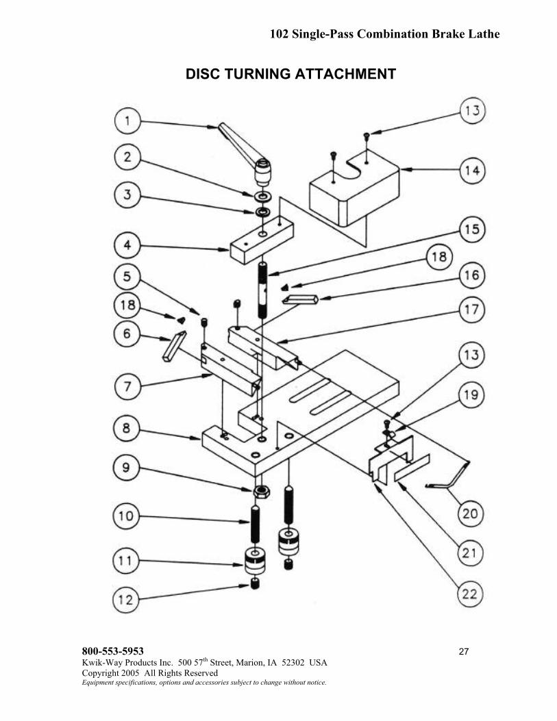
DISC TURNING ATTACHMENT
800-553-5953 27
Kwik-Way Products Inc. 500 57
th
Street, Marion, IA 52302 USA
Copyright 2005 All Rights Reserved
Equipment specifications, options and accessories subject to change without notice.

102 Single-Pass Combination Brake Lathe
DISC TURNING ATTACHMENT
ITEM PART # DESCRIPTION QTY
1 003-0049-40 Kipp Handle 1
2 000-1155-50 ½” SAE Washer 1
3 000-1183-30 ½” x .021 Bow Washer 1
4 102-1004-00 Bar, Clamp 1
5 000-0540-70 5/16-18” X ¼” Soc Head Ovp SS 2
6 109-1091-00 Holder, Tool Bit, Left 1
7 102-1004-20 Assembly, Tool Holder, Left 1
8 102-0120-00 Base, Rotor Truer 1
9 000-1070-18 ½-20” Jam Nut 1
10 102-1010-00 Feed Screw 2
11 110-1008-33 Size Control Knob 2
12 000-0495-14 ½-20: x ½” Soc. Pt. S.S. 2
13 000-0595-01 Button Head C.S. 2
14 102-1092-23 Cover, Tool Bar 1
15 102-1001-10 Toolbar Clamp Stud 1
16 109-1090-02 Holder, Tool Bit, Right 1
17 102-1004-40 Assembly, Tool Holder, Right 1
18 109-1092-23 Carbide Insert (Pkg/10) As Reqd
19 000-1242-22 Victor Holddown Clip 1
20 000-1842-09 Tension Spring 1
21 000-6613-30 Decal, Tool Adjust 1
22 102-1039-02 Plate, Marker 1
800-553-5953 28
Kwik-Way Products Inc. 500 57
th
Street, Marion, IA 52302 USA
Copyright 2005 All Rights Reserved
Equipment specifications, options and accessories subject to change without notice.

102 Single-Pass Combination Brake Lathe
CROSS FEED ASSEMBLY
800-553-5953 29
Kwik-Way Products Inc. 500 57
th
Street, Marion, IA 52302 USA
Copyright 2005 All Rights Reserved
Equipment specifications, options and accessories subject to change without notice.

102 Single-Pass Combination Brake Lathe
CROSS FEED ASSEMBLY
ITEM PART # DESCRIPTION QTY
1 000-0391-10 10-32 x 1/2 Pan Head Type F ZP 4
2 000-0485-26 1/4-20 x 3/8 Socket Cup Pt SS 1
3 000-0487-75 5/16-18 x 5/16 Nyloc Cup Pt SS 4
4 000-0490-34 3/8-16 x 3/8 Socket Cup Pt SS 2
5 000-0501-05 10-24 x 1/4 Socket Flat Pt. SS 1
6 000-0592-24 1/4-20 x ½ Button Head CS 1
7 000-0595-01 10-24 x 3/8 Button Head CS 12
8 000-0595-04 10-24 x 1/2 Button Head CS 2
9 000-0595-32 10-32 x ½ Button Head CS 4
10 000-1045-15 3/8-16 Hex Jam Nut ZP 2
11 000-1150-10 3/16 Wrought Iron Washer ZP 1
12 000-1150-37 5/16 Wrought Iron Washer ZP 1
13 000-1170-21 #10 Internal Lockwasher ZP 4
14 000-1170-65 ½ Internal Switch Lockwasher ZP 1
15 000-1170-75 Washer, Wavy 1.19 ID x 1.48 OD 1
16 000-1202-10 Switch, Toggle Spdt 1
17 000-1210-20 Boot, Toggle 1
18 000-1740-00 Wiper 1
19 000-1900-01 Cover, Ball Valve Oil Hole 1
20 000-2602-26 Bushing, Strain Relief 90º 1
21 000-2900-00 Bellows, Way Protector 1
22 000-4400-10 Handle, Revolving 1
23 000-5301-12 Pulley, Gearbelt 21T w/(2) SS 60Hz 1
24 000-5301-28 Pulley, Gearbelt 28T w/(2) SS 50 Hz 1
25 000-6608-30 Decal “In-Out” (102) 1
26 000-6608-35 Decal “in-Out (1021) 1
27 000-6611-22 Decal “0-100” 1
28 000-9200-53 Bushing, Oilite .50 ID x .75 OD x .75 2
29 001-1899-90 Gearbelt 1/5P-100 x LO37 60Hz 1
30 001-1899-91 Gearbelt, 1/5P-110 x LO37 50Hz 1
31 001-1938-62 Gearmotor, 115V (7 RPM) CCW (1021) 1
32 001-1938-64 Gearmotor, 115V (7 RPM) CW (102) 1
33 004-0015-59 Knob, T-Bar 1
34 015-0121-02 Plug, Guide 4
35 023-0201-90 Plug, .25 x .19 Long 1
36 060-1125-00 Assy, T-Bar ¼-20 x ½ 1
37 102-0110-00 Slide, Cross (102) 1
38 102-1001-10 Stud, Clamp 3.53 Long (102) 1
39 102-1019-00 Bracket, Crossfeed Trip 1
40 102-1019-40 Bracket, Feed Trip (102) 1
800-553-5953 30
Kwik-Way Products Inc. 500 57
th
Street, Marion, IA 52302 USA
Copyright 2005 All Rights Reserved
Equipment specifications, options and accessories subject to change without notice.

102 Single-Pass Combination Brake Lathe
CROSS FEED ASSEMBLY
800-553-5953 31
Kwik-Way Products Inc. 500 57
th
Street, Marion, IA 52302 USA
Copyright 2005 All Rights Reserved
Equipment specifications, options and accessories subject to change without notice.
102 Single-Pass Combination Brake Lathe
CROSS FEED ASSEMBLY
ITEM PART # DESCRIPTION QTY
41 102-1020-00 Plate, Wiper – Cross Slide 1
42 102-1021-00 Retainer, Bellows 1
43 102-1022-01 Plate, End – Cross Slide 1
44 102-1023-00 Gib, Cross Slide 1
45 102-1025-00 Pulley, Driven – Cross Slide 21T 1
46 102-1026-50 Assy, Crossfeed Screw RH (102) 1
47 102-1026-67 Assy, Crossfeed Screw LH (1021) 1
48 102-1027-04 Handwheel 6” Diameter 1
49 102-1027-20 Collar, Handwheel 1
50 102-1028-00 Nut, Cross Slide RH (102) 1
51 102-1028-17 Nut, Cross Slide LH (1021) 1
52 102-1090-00 Cord, Crossfeed 1
53 104-0110-00 Slide, Cross (1021) 1
54 104-0131-00 Cover, Crossfeed Gearmotor 1
55 104-1001-00 Stud, Clamp 3.78 Long (1021) 1
56 104-1016-00 Bracket, Feed Trip (1021) 1
57 104-1041-00 Bracket, Crossfeed Gearmotor 1
58 104-3011-00 Slide, Feed 1
59 105-1001-59 Retainer, Curtain 1
60 105-1026-07 Curtain 1
61 105-1511-50 Washer, Nylon Thrust 1
800-553-5953 32
Kwik-Way Products Inc. 500 57
th
Street, Marion, IA 52302 USA
Copyright 2005 All Rights Reserved
Equipment specifications, options and accessories subject to change without notice.

102 Single-Pass Combination Brake Lathe
ATTACHMENTS AND ACCESSORIES
800-553-5953 33
Kwik-Way Products Inc. 500 57
th
Street, Marion, IA 52302 USA
Copyright 2005 All Rights Reserved
Equipment specifications, options and accessories subject to change without notice.

102 Single-Pass Combination Brake Lathe
ATTACHMENTS AND ACCESSORIES
ITEM PART # DESCRIPTION QTY
1 000-0540-76 5/16-18 X ½ Soc. Head Oval Pt. SS 2
2 000-1070-18 ½-20 Hex Jam Nut ZP 1
3 102-1039-02 Marker Plate 1
4 000-1242-22 Hold Down Clip 1
5 000-1842-09 Tension Spring 1
6 000-6613-30 Tool Bar Adjustment Decal – Disc 1
7 000-1155-50 ½ SAE Washer 1
8 000-1183-30 Bowed Washer – ½ 1
9 102-0120-00 Rotor Truer Base 1
10 102-1005-00 Spacer 1.38 Diameter x 1.56 1
11 102-1001-60 Toolbar Clamp Stud 1
12 102-1010-00 Tool Holder Feedscrew 2
13 000-0495-14 ½-20 x ½ Soc Cup Pt SS 2
14 102-1004-00 Clamp Bar 1
15 102-1004-20 Left Tool Holder Assembly 1
16 102-1004-40 Right Tool Holder Assembly 1
17 109-1090-02 Right Hand Insert Tool Bit 1
18 109-1091-00 Left Hand Insert Tool Bit 1
19 110-1008-33 Size Control Knob 2
20 102-1005-50 Hex Tool Bar 1
21 000-0540-76 5/16-18 x ½ Soc. Head Oval Pt. SS 1
22 102-1006-00 Tool Bar Holder Weldment 1
23 109-1092-23 Carbide Inserts, Set of 10 As Reqd
24 109-1032-09 Spacer, Short 1
25 109-1012-06 Bell Clamp, 4-11/16” Diameter 1
26 109-1011-09 Bell Clamp,4” Diameter 1
27 101-0235-40 Bell Clamp, 5-12/16” Diameter 2
28 101-0236-05 Cone 1 1
29 101-0237-02 Cone 2 1
30 101-0243-00 Cone L 1
31 101-0260-02 Double Taper Adapter 0, 1.30”-1.66” 1
32 101-0260-22 Double Taper Adapter 2, 1.70”-2.06” 1
33 101-0260-32 Double Taper Adapter 3, 2.07”-2.44” 1
34 101-0260-42 Double Taper Adapter 4, 2.45”-2.81” 1
35 000-1806-70 Compression Spring 1
36 101-0230-10 Dampener Strap Assembly – Drum 1
37 108-1061-00 Vented Disc Dampener 1
38 108-1060-00 Dampener, Solid Disc 1
39 000-8700-21 1-1/2 Armstrong Wrench – NS 1
40 000-8700-00 5/16 Square Wrench – NS 1
41 See Page Arbor
42 102-1029-50 Tool Bar Cover – NS 1
43 000-0600-66 5/32 T-Handle Hex Wrench – NS 1
44 109-1033-06 2” Spacer – NS 2
800-553-5953 34
Kwik-Way Products Inc. 500 57
th
Street, Marion, IA 52302 USA
Copyright 2005 All Rights Reserved
Equipment specifications, options and accessories subject to change without notice.

102 Single-Pass Combination Brake Lathe
WIRE TERM BLOCK
ITEM PART # DESCRIPTION QTY
1 000-1240-95 Term, QD (12-10) Ins, ¼ 1
2 000-1241-00 Term, QD (16-14) Fully Ins, ¼ 3
3 000-1242-45 Term, Flag (16-14) Fully Ins, ¼ 1
4 000-1242-49 Term, Flag (16-14) ¼ 2
6 000-1254-74 Term, Eye (16-14) ¼ 1
7 Term, Spade (16-14) Ins #8 1
8 Electric Wire 16GA Brown MTW 5.0” 1
9 Electric Wire 16GA Brown MTW 19.0” 1
10 000-2410-24 Electric Wire 16GA Black MTW 9.0” 1
11 000-2410-40 Electric Wire 16GA Green MTW 19.5” 1
12 000-2410-59 Electric Wire 16GA Red MTW 9.0” 1
13 000-2410-75 Electric Wire 16GA White MTW 19.0” 1
14 003-0003-38 Cable Tie 3.65 Large White 6
800-553-5953 35
Kwik-Way Products Inc. 500 57
th
Street, Marion, IA 52302 USA
Copyright 2005 All Rights Reserved
Equipment specifications, options and accessories subject to change without notice.

102 Single-Pass Combination Brake Lathe
QUICK DISCONNECT TERMINAL BLOCK
ITEM PART # DESCRIPTION QTY
1 000-1240-95 Term, QD (12-10) Ins ¼ 1
2 000-1241-00 Term, QD (16-14) Fully Ins ¼ 1
3 000-1242-45 Term, Flag (16-14) Fully Ins ¼ 5
4 000-1242-49 Term, Flag (16-14) ¼ 2
6 000-1254-74 Term, Eye (16-14) ¼ 1
7 Term, Spade (16-14) Ins #8 1
8 Electric Wire 16GA Brown MTW 5.0” 1
9 Electric Wire 16GA Brown MTW 19.0” 1
10 000-2410-24 Electric Wire 16GA Black MTW 9.0” 1
11 000-2410-40 Electric Wire 16GA Green MTW 19.5” 1
12 000-2410-59 Electric Wire 16GA Red MTW 9.0” 1
13 000-2410-75 Electric Wire 16GA White MTW 19.0” 1
14 003-0003-38 Cable Tie 3.65 Large White 6
800-553-5953 36
Kwik-Way Products Inc. 500 57
th
Street, Marion, IA 52302 USA
Copyright 2005 All Rights Reserved
Equipment specifications, options and accessories subject to change without notice.

102 Single-Pass Combination Brake Lathe
ELECTRICAL PARTS (115V)
800-553-5953 37
Kwik-Way Products Inc. 500 57
th
Street, Marion, IA 52302 USA
Copyright 2005 All Rights Reserved
Equipment specifications, options and accessories subject to change without notice.

102 Single-Pass Combination Brake Lathe
ELECTRICAL PARTS (115V)
ITEM PART # DESCRIPTION QTY
1 000-0236-16 ¼-20 x ½ Rd Head MS Brass 2
2 000-1170-48 ¼ Internal Lockwasher 2
3 000-1202-10 SW Toggle Spst (On-Off) 2 Wire 1
4 000-1202-19 SW Toggle Spst (On-Off) ¼ Tab 1
5 000-1209-01 Switch, Rocker Spst ¼ Tab 1
6 000-1209-04 Switch, Rocker Spdt ¼ Tab 1
7 000-1241-41 Wire Nut Blue 3
8 000-1242-45 Term, Flag (16-14) Fully Insul ¼ 1
9 000-1252-18 Lamp, Work 1
10 000-1254-74 Term, Eye (16-14) ¼ 1
11 000-1261-01 Cordset, 16-3SJO 115V 1
12 000-5301-12 Pulley, Gearbelt 2IT w/(2) SS 2
13 001-1899-90 Gearbelt, Crossfeed 100 x L037 1
14 001-1899-99 Gearbelt, Feed 120 x L037 1
15 001-1938-64 Gearmotor, Crossfeed Hi Torque 115V 1
16 001-1938-68 Gearmotor, Feed 115V 1
17 001-1950-00 Motor, Spindle 115/230V-50/60Hz 1Ph 1
*18 004-035-00 Block, Terminal 3 Pole 1
19 102-1090-00 Cord, Crossfeed 1
*20 102-1091-04 Harness, Wiring 102 1
* NOTE: If Item 18 has quick-connect tabs, use wiring harness 102-1091-02 for service.
800-553-5953 38
Kwik-Way Products Inc. 500 57
th
Street, Marion, IA 52302 USA
Copyright 2005 All Rights Reserved
Equipment specifications, options and accessories subject to change without notice.

102 Single-Pass Combination Brake Lathe
ELECTRICAL PARTS (230V)
800-553-5953 39
Kwik-Way Products Inc. 500 57
th
Street, Marion, IA 52302 USA
Copyright 2005 All Rights Reserved
Equipment specifications, options and accessories subject to change without notice.

102 Single-Pass Combination Brake Lathe
ELECTRICAL PARTS (230V)
ITEM PART # DESCRIPTION QTY
1 000-0209-07 10-24 x 1.00 Round Head MS – ZP 3
2 000-0236-16 ¼-20 x ½ Round Head MS – Brass 2
3 000-1117-00 10-24 U-Nut 4
4 000-1170-48 ¼ Internal Lockwasher 2
5 000-1202-10 SW, Toggle – SPST (On-Off) – 2 Wire 1
6 000-1202-19 SW, Toggle – SPST (on-Off) ¼ Tab 1
7 000-1209-01 Switch, Rocker – SPST ¼ Tab 1
8 000-1209-04 Switch, Rocker – SPDT ¼ Tab 1
9 000-1241-41 Wire Nut – Blue 3
10 000-1242-45 Term, Flag (16-14) Fully Insul ¼ 1
11 000-1242-68 Term, QD (22-16) Fully Ins ¼ Male 1
12 000-1242-70 Term, QD (16-14) Fully Insul ¼ F 1
13 000-1252-18 Lamp, Work 1
14 000-1254-74 Term, Eye (16-14GA) ¼ 1
15 000-1261-28 Cordset, 16-3SJO – 230V 1
16 000-1274-90 Transformer – 230/115V-150VA 1
17 000-5301-12 Pulley, Gearbelt 2IT 60Hz 2
18 000-5301-28 Pulley, Gearbelt 28T 50Hz 2
19 000-6609-14 Decal, “Caution 230V Bulb” 1
20 001-1601-76 Bulb, Light 60W 230V 1
21 001-1899-90 Gearbelt, Crossfeed 100 x L037 60Hz 1
22 001-1899-91 Gearbelt, Crossfeed 110 x L037 50Hz 1
23 001-1899-98 Gearbelt, Feed 130 x L037 50Hz 1
24 001-1899-99 Gearbelt, Feed 120 x L037 60Hz 1
25 001-1938-64 Gearmotor 7RPM Hi Torque 115V 2
26 001-1950-00 Motor, Spindle 115/230V 50/60Hz – 1Ph 1
*27 004-0035-00 Block, Terminal 3 Pole 1
28 102-1090-00 Cord, Crossfeed 1
*29 102-1091-04 Harness, Wire 102 1
* NOTE: If Item 27 has quick connect tabs, use wiring harness 102-1091-02 for service.
800-553-5953 40
Kwik-Way Products Inc. 500 57
th
Street, Marion, IA 52302 USA
Copyright 2005 All Rights Reserved
Equipment specifications, options and accessories subject to change without notice.

Kwik-Way Products Inc.
500 57
th
St., Marion, IA 52302 USA
319/377-9421
319/377-9101 (FAX)
800/553-5953
www.kwik-way.com