*10792bag* 10792bag 07 13 gmc 1500 diy prerunner bumper
TRANSCRIPT

1
07-13 GMC 1500 DIY PreRunner Bumper
*10792BAG*
10792BAG
921107920
Thank you for choosing Rough Country for all of your suspension needs.
Rough Country recommends that a certified technician install this system. In addition to these instructions, professional knowledge of disassemble/reassembly procedures as well as post installation checks must be known. Attempts to install this system without this knowledge and expertise may jeopardize the integrity and/or operating safety of the vehicle. Please read all the instructions before beginning the installation. Check the kit hardware against the ‘’Kit Contents’’ list below. If question exist, please call us @1-800-222-7023. We will be happy to answer any questions concerning this product. Check all fasteners for proper torque. Check to ensure for adequate clearance between all components. Check and retighten wheels at 50 miles and again at 500 miles. Periodically check all hardware for tightness. Be sure you have all the needed parts and understand where they go. Also, please review the “Tools Needed” list to be certain you have the necessary tools to complete the installation.
PRODUCT USE INFORMATION
As a general rule, the taller a vehicle is the easier it will roll. We strongly recommend that seat belts and shoulder harnesses be worn at all times. Braking performance and capabilities are decreased when signifi-
cantly larger/heavier tires and wheels are used. Do not add, alter, or fabricate any factory or after-market parts which increase vehicle height over the intended height of the Rough Country product purchased. Rough Country makes no claims regarding lifting devices and excludes any and all implied claims. We will not be responsible for any product that is altered.
NOTICE TO DEALER AND VEHICLE OWNER
Any vehicle equipped with any Rough country product must have the “Warning to Driver” decal installed on the sun visor or dash. The decal is to act as a constant reminder for whoever is operating the vehicle of its
unique handling characteristics. INSTALLING DEALER—It is your responsibility to install the warning decal and to for-ward these installation instructions on too the vehicle owner for review and to be kept in the vehicle for its service life.

2
07-13 GMC PreRunner Bumper
KIT CONTENTS: Center Skin
Pass Inner Wing Driver Inner Wing Pass Middle Wing
Driver Middle Wing Pass Outer Wing Drive Outer Wing Wing End Cap (2) Pass Bottom Wing Driver Bottom Wing 30” Light Bar Mount 10” Light Bar Mount
Bumper Shim Bumper Support
Pass Brace Driver Brace Winch Mount
Fairlead Mount Fairlead Support (2)
Frame Mount (2) Frame Mount Front Plate (2)
30” Light Trim Ring 30” Light Grill Block Off Plate
10” Light Trim Ring (2) 10” Light Block Off Plate (2) Winch Grill Block Off Plate
1/4” Bumper Shims (2)
TOOLS NEEDED: Jack
Safety Stands Wheel Chocks
Marker Tape Measure
Welder Grinder Sander
Clamps/Locking Pliers Razor Knife
Wire Strippers/Cutters Drill
3/4” Bit Allen Wrench Set (SAE/Metric)
Metric Wrench/Socket 10mm 15mm 18mm 19mm 21mm
HARDWARE INCLUDED: 1/4” Stainless Allen Bolt (24)
1/4” Stainless Black Allen Bolt (24) 1/4” Washer (24) 1/4” Raw Nut (7)
10mm Allen Bolt (5) 10mm Nut (3)
10mm Washer (6) 12mm Black Allen Bolt (2)
12mm Flange Nut (8) 12mm Raw Nut (2) 12mm Washer (8)
Bolt Tab (4) 1/4” Spacer (2)
OPTIONAL ITEMS: PreRunner Skid Plate
Part # 10” Slim Line Light Bar
Part #(70410BL or 70410) 30” Single Row Light Bar Part # (7030BL or 7030) 9,500/12,000lb Winch
Part # (PRO9500S or PRO1200S) Extension Cable Part # (RS130-1)
6” Length of 18 Gauge Wire (4) (Installer Supplied)
18 Gauge Butt Connectors (8) (Installer Supplied)
5/16” Self Tapping Screws (4) (Installer Supplied)
5/16” Flat Washers (4) (Installer Supplied)
3 Quart Washer Tank (1) (usplastic.com Item number 8818)
Washer Tank Cap (1) (usplastic.com Item number 11489)

3
Bumper Removal and assembly 1. Park your vehicle on a clean flat surface, engage the parking brake and block the rear tires. 2. Open the hood and disconnect the negative terminal on the battery. 3. Remove the core support shroud plastic push pins and the shroud. Photo 1 4. Set aside for later. Photo 2
Photo 1 Photo 2
Photo 3 Photo 4
Photo 5 Photo 6
Remove the core support shroud. Remove the core support shroud.
Remove the filler panel hardware. Remove the filler panel sides.
Remove the grill clips. Pull grill and filler panel off.
5. Remove the filler panel hardware on both sides of the vehicle using a 7mm socket. Photo 3 6. Grab the filler panel and pull out and down to pop out of the retainer. Photo 4
7. Remove the upper grill hardware using a 10mm socket. Have a helper reach between the core support and the grill to pinch the metal clips holding the grill in place while you pull back away from the vehicle. This is best done by two people to keep the grill from popping back into place. Photo 5
8. Pull the grill and filler panel away from the vehicle and set aside. Photo 6

4
9. Remove the filler panel retainer using an extension and 10mm socket. Discard all. You will have to look into the holes to see the bolts holding this piece to the fender. Photo 7
10. Remove the flexible rubber air dam between the bumper and the core support. It is held in by plastic push pins. Dis-card all. Photo 8
Photo 7 Photo 8
Photo 9 Photo 10
Photo 11 Photo 12
Remove the filler panel retainer. Remove rubber air dam.
Disconnect the auxiliary lights. Remove the bumper support.
Remove the frame hardware. Remove the capture bolts.
11. Disconnect the auxiliary lights. Photo 9 12. Remove the bumper side supports from the frame and bumper using a 15mm socket. Photo 10
13. Remove the bumper frame mount hardware using a 21mm socket. Photo 11 14. Using a helper, support the bumper while removing the captured bolts and pull the bumper away from the vehicle
and set aside. Photo 12

5
15. Remove the factory tow hood hardware using a 18mm socket. Save all for reinstallation later. Photo 13 16. Inside the fender well there are two bolts holding the liner to the washer tank. Remove using a 10mm socket. Photo
14
Photo 13 Photo 14
Photo 15 Photo 16
Photo 17 Photo 18
Remove the tow hooks. Remove the washer tank hardware.
Remove and plug the rubber line. Disconnect the pump and float.
Remove the washer tank hardware. Remove the spare batt tray.
17. Remove the rubber washer hose from the plastic hard line and use on of the removed bolts to plug the rubber wash-er hose. Photo 15
18. Disconnect the washer tank pump and the float electrical connectors. Photo 16
19. Pull back the inner liner and locate the inner bolt holding the washer tank to the core support. Remove using a 10mm socket. Discard. Photo17
20. Under the hood, remove the spare battery tray using a 10mm socket and set aside. Photo 18

6
21. Have a helper hold the washer tank while you remove the remaining bolt holding the tank in place using a 10mm socket. Once removed, set aside and reinstall the spare battery tray using the factory hardware. Torque to 5 ft-lbs. Photo 19
22. In the passenger wheel well, remove the two bolts holding the inner brace assembly using a 10mm socket. Photo 20
Photo 19 Photo 20
Photo 21 Photo 22
Photo 23 Photo 24
Remove the washer tank. Remove the liner brace hardware.
Remove the liner support. Remove the headlight assembly.
Remove the filler panel retainer. Remove filler panel from grill.
23. Peel the inner liner back and remove the remaining bolts holding the liner support to the core support. Discard all. Photo 21
24. Remove the headlights from the vehicle using a 10mm socket. This is to access the filler panel retainer that needs to be removed for proper fitment of the new bumper. Photo 22
25. Flip the headlight around and remove the two screws holding the filler panel retainer to the headlight assembly using a T15 Torx bit. Discard all. Reinstall the headlights using the factory hardware. Photo 23
26. Remove the filler panel from the grill by pressing in the factory plastic clips along the length of the grill. Discard the filler panel. Photo 24

7
27. With the filler panel removed from the grill, mark a line connecting the clip holes where the filler panel snapped into place. You will be cutting this off flush with the bottom of the grill. Do not cut into any of the chromed or painted area. You only want to remove the filler panel retainer plastic. Sand any burrs smooth. Photo 25
28. Reinstall the grill using the metal clips and the factory hardware. Do not over tighten the bolts. The plastic is brittle and can crack if over tightened. This completes the tear down process for the front end. Photo 26
Photo 25 Photo 26
Photo 27 Photo 28
Photo 29 Photo 30
Mark and cut the grill. Reinstall cut grill.
Lay out the inner bracket parts. Lay out the skin parts.
Lay out sub assembly 1. Tack weld the side and skin support.
29. The instructions from here on out will be more of a guide and proper welding, clamping and measurements tech-niques are on the assembler for the assembly of the bumper.
30. Lay out the inner bracket parts. Photo 27 31. Lay out the skin parts. Make sure you have all the parts before proceeding. Photo 28
32. Start with the inner bracket assembly. There is the winch tray, side supports, and skin supports. Photo 29 33. Lock a side support and skin support together as shown. There is a tab for the side support to lock to the front of the
skin support. Tack weld as shown. Repeat the process for the opposite side. Photo 30

8
34. Using the tab on the skin support, install to the winch tray. Use a square to make sure the side support is perpendic-ular to the winch tray. You may end up with a small gap at the side support and the winch tray. Just make sure the side support is square. Tack weld the side support to the winch tray. Repeat for both sides. Photo 31
35. Once everything is square, weld the side support to the winch tray. Weld all inner corner joints. DO NOT weld the outside joint of the side support. This could cause interference with the bolt tab later for installation. Photo 32
Photo 31 Photo 32
Photo 33 Photo 34
Photo 35 Photo 36
Square the side support. Weld the support and winch tray.
Lay out the frame mounts. Weld the frame mounts.
Bolt trim ring to 30” light bar mount. Place center skin on blocks.
36. Lay out the frame mount and plates. Photo 33 37. Install the frame mounts to the plates using the tab and slot. Weld all corners. Photo 34
38. Locate the 30” light bar mount, and the trim ring. Bolt the trim ring to the light bar mount using the provided 1/4” bolts, washers and nuts. Photo 35
39. Locate the center skin and lay the ends on a couple blocks face down. Make sure that you are not blocking the cen-ter opening. Photo 36
DO NOT weld outside joints.

9
40. Lay the assembled light bar mount into the hole using the trim ring to center the location of the light bar mount. Once the center is verified, tack weld the light bar to the center skin as shown. DO NOT weld the sides of the light bar mount. Photo 37
41. Locate the 10” light bar mount, and the trim ring. Bolt the trim ring to the light bar mount using the provided 1/4” bolts, washers and nuts. You will notice that there are two bolt patterns on this mount. You will be making a left and right hand version, so bolt the trim rings opposite of each other. Photo 38
Photo 37 Photo 38
Photo 39 Photo 40
Photo 41 Photo 42
Picture info.
Weld the inner bracket to the skin. Tack weld the inner wing.
44. Install the inner bracket assembly into the skin as shown. Make sure to center the inner bracket assembly to the cen-ter skin. Once this has been verified, weld the bumper supports and the winch tray to the center skin. Photo 41
45. Locate the inner wings. With the center skin laying face down, hold the inner wing in place. Line up all the bend lines. You will want to leave about a .030” gap between the parts. Use of clamps may be necessary to make the skin line up in places. Once all has been verified, tack weld the inner wing strong enough that it will hold. Repeat the pro-cess for the opposite side for all of the wing assembly. Photo 42
42. Locate the wings with the light bar openings and lay the ends on a couple blocks face down. Make sure that you are not blocking the center opening. Lay the assembled light bar mount into the hole using the trim ring to center the lo-cation of the light bar mount. Once the center is verified, tack weld the light bar to the center skin as shown. Remove and set aside the trim rings. Photo 39
43. Locate the 1/4” raw nuts. Use one of the provided bolts, install to the lower skid plate holes in the center skin. Tack weld these in place making sure to not get any weld slag onto the threads of the bolt. Repeat for all 7 holes. Photo 40
Bolt 10” trim ring to mount.
Pass side shown.
Tack weld the mount to the skin. Weld 1/4” nuts to center skin.
Pass side shown. Repeat x7

10
46. Tack weld the center wing in place. Photo 43 47. Tack weld the outer wing in place. Photo 44
Photo 43 Photo 44
Photo 45 Photo 46
Photo 47 Photo 48
Tack weld the center wing. Tack weld the outer wing.
Tack weld the end cap. Tack weld the grill end cap.
Tack weld the bottom wing. Install the frame mounts.
48. Tack weld the wing end caps. Photo 45 49. Tack weld the grill end caps. Photo 46
50. Tack weld the bottom wing. Photo 47 51. Install the bumper mounts to the frame using the factory hardware. DO NOT tighten at this time. You will be test fit-
ting the bumper for proper clearances. Photo 48

11
52. Install the bumper to the frame mounts using the provided bolt tabs and 12mm nuts, and washers. Photo 48 53. Adjust the bumper as needed to get everything lined up. Photo 50
Photo 49 Photo 50
Photo 51 Photo 52
Photo 53 Photo 54
Install the bumper to the frame mounts. Adjust Bumper.
Check gaps. Finish welding joints.
Locate the fairlead mount. Weld the 12mm nuts.
54. Check all gaps. If you find after tightening all the mounts that you have some twist or parts that are not lining up, break the bottom wing tack welds from the wings. You can twist the wings into place. Once you are satisfied with the fitment, tack weld the lower wings back in place. Remove the bumper for final welding. Photo 51
55. Finish welding all the joints. Work your way around each one to avoid warping. Once all joints have been welded and cooled, use a flap disc or grinder to smooth all the welds for a clean look. Photo 52
56. Locate the fairlead mount pieces. Photo 53 57. Install the supplied 12mm raw nuts and 12mm Allen bolts to the center skin. Weld the nuts to the skin. Photo 54

12
58. Install the side supports to the center skin as shown using the tab and slots. Photo 55 59. Weld the side supports to the center skin. Photo 56
Photo 55 Photo 56
Photo 57 Photo 58
Photo 59 Photo 60
Attach the side supports. Weld the side supports.
Install the winch. Install the fairlead mount.
Install block off plate. Install trim ring and light.
60. Have the bumper and pieces coated in your preferred choice of color paint, or powder coat. 61. If you are installing a Rough Country 95,00 or 12,000 lb winch with synthetic rope, install the provided square nuts
that came in the hardware bag with the winch into the base of the winch. Have an assistant hold the winch up to the bumper while you install the provided 10mm button head bolts into the base of the winch. You will find that you have to access the lower holes through the front fairlead opening and the upper holes through the light bar opening. Make sure to route the winch cable through the hole in the front of the bumper. Once all are started, torque the lower bolts to 30 ft-lbs. Photo 57
62. Remove the upper button head bolts, and install the winch fairlead. Install the remaining 10mm button head bolt (with the head facing the winch), washers, and nut. Torque all to 30 ft-lbs. Photo 58
63. If not installing side lights, install the provided block off plate with your choice of black or stainless 1/4” hardware. Photo 59
64. If installing any of the lighting options, use the hardware provided in the light boxes. Snug the light hardware down enough to hold the lights tightly in place. Install any necessary washers or spacers needed to make the lights fit. This bumper is designed around the Rough Country 30” single row led light bar, and 10” slim line led light bars in black or chrome series. Photo 60

13
65. If not installing a center light bar, you will install the grill option using your choice of the provided 1/4” hardware. If you are installing a center light bar, you can install either the grill option to “hide” the light or you can install the trim ring. Photo 61
66. Using an assistant, install the bumper to the vehicle as done in the test fitting steps. Adjust until all gaps are good. Torque the bumper mounts to 95 ft-lbs and the tow hook to 50 ft-lbs. Due to frame variations, you may need to use the supplied shim between the frame mount and bumper to clear the winch controller. Photo 62
Photo 61 Photo 62
Photo 63 Photo 64
Install the grill if not using a light. Install the bumper.
Mark and trim plastic. Mark and trim plastic.
67. Once the bumper is installed and all gaps are set, mark the inner liners as shown. Photo 63 68. Use a razor knife or other suitable cutting tool, trim the plastic so that it tucks nicely behind the bumper end caps.
Repeat for both sides. Photo 64
69. Install the winch fairlead using the provided 12mm button head bolts from the bumper hardware bag. Torque to 30 ft-lbs. If you are not using a winch, install the winch block off grill using the 12mm button head bolts and 1/4” thick spacers. Line up until all the gaps are even and torque the bolts to 5 ft-lbs.
70. If you installed a winch and/or lights, run the electrical accordingly. 71. If you purchased the winch control extension cable, a good place to mount this is on the grill shell under the hood.
Access this area by removing the core support cover plastic rivets and set aside. 72. Make a template using the extension base. Photo 65 73. Drill out the holes and bolt to the grill shell. Run the cable to the winch control box. Photo 66
Photo 65 Photo 66
Mark the grill shell. Install the extension.
14
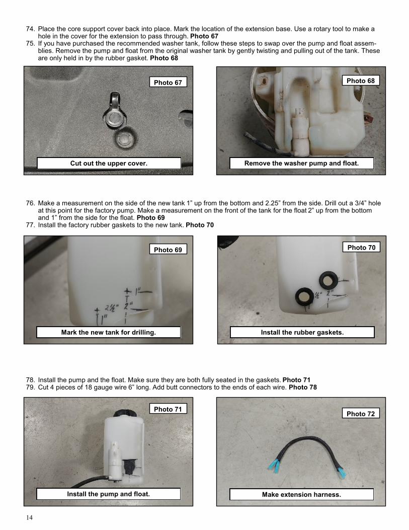
74. Place the core support cover back into place. Mark the location of the extension base. Use a rotary tool to make a hole in the cover for the extension to pass through. Photo 67
75. If you have purchased the recommended washer tank, follow these steps to swap over the pump and float assem-blies. Remove the pump and float from the original washer tank by gently twisting and pulling out of the tank. These are only held in by the rubber gasket. Photo 68
76. Make a measurement on the side of the new tank 1” up from the bottom and 2.25” from the side. Drill out a 3/4” hole at this point for the factory pump. Make a measurement on the front of the tank for the float 2” up from the bottom and 1” from the side for the float. Photo 69
77. Install the factory rubber gaskets to the new tank. Photo 70
78. Install the pump and the float. Make sure they are both fully seated in the gaskets. Photo 71 79. Cut 4 pieces of 18 gauge wire 6” long. Add butt connectors to the ends of each wire. Photo 78
Photo 67 Photo 68
Photo 69
Cut out the upper cover. Remove the washer pump and float.
Mark the new tank for drilling.
Photo 70
Photo 71 Photo 72
Install the rubber gaskets.
Install the pump and float. Make extension harness.

15
Photo 73 Photo 74
Photo 75
Cut and extend the wire harness. Install the rubber line.
Mount the tank.
80. Make sure the battery is disconnected, cut the wire harness for the pump and the float. Strip the wires and install the install the 6” length of wire making sure to match the original harness colors on both ends. Repeat this for the re-maining three wires. Route the extended wire harness to the inside of the engine bay and connect the pump and float electrical connectors. Photo 73
81. Route the washer tank hard line to the pump. Cut the line and install to the rubber line on the pump. Photo 74
82. Mount the tank into the vehicle fender well using some 5/16” self tapping bolts. Photo 75 83. Reconnect the battery and test all electrical components for proper operation. Photo 76
84. For a finished look on the frame, the lower frame horns can be removed. This is also necessary if you purchased the optional lower skid plate designed for the bumper. Use a suitable cutting device, trim the frame horns off flush with the frame. (Plasma cutter shown.) Grind any burrs and paint using a quality rust preventative paint or under liner. Reconnect the battery. Step back and admire all the hard work you put into your new DIY bumper. Photo 77
Photo 76
Photo 77
Add fluid and test.
Cut off frame horns.

16
By purchasing any item sold by Rough Country, LLC, the buyer expressly warrants that he/she is in compliance with all applicable , State, and Local laws and regulations regarding the purchase, ownership, and use of the item. It shall be the buyers responsibility to comply with all Federal, State and Local laws governing the sales of any items listed, illustrated or sold. The buyer expressly agrees to indemnify and hold harmless Rough Country, LLC for all claims resulting directly or indirectly from the purchase, ownership, or use of the items.