11 - 2020 ild
TRANSCRIPT

AQU
ACIA
TPO
WER
ILD
CLA
SSIC
RH
E/R
HE-
Z/PH
E&
VER
TIC
ALE
PH
E
11 - 2020
EN7565702-01
Instruction manual

CONTENTS
1 - FOREWORD ............................................................................................................................................................................ 31.1 - GENERAL INFORMATION ................................................................................................................................................. 31.2 - PROTECTION AGAINST ELECTROCUTION .................................................................................................................... 31.3 - USE ..................................................................................................................................................................................... 3
2 - RECEIPT ................................................................................................................................................................................. 4
3 - HANDLING .............................................................................................................................................................................. 5
4 - DESCRIPTION OF THE UNIT & TECHNICAL CHARACTERISTICS .................................................................................... 74.1 - DESCRIPTION OF THE UNIT ............................................................................................................................................ 74.2 - LOCATION OF COMPONENTS ......................................................................................................................................... 94.3 - TECHNICAL CHARACTERISTICS ....................................................................................................................................11
5 - INSTALLATION AND INSTALLATION CONNECTIONS ...................................................................................................... 175.1 - OUTDOOR INSTALLATION ("Classic PHE" and "Classic RHE/RHE-Z" model only) ....................................................... 175.2 - FLOWAY RHEZ 10000 & 15000 : PROCEDURE FOR ROOF ASSEMBLY...................................................................... 185.3 - FLOWAY CLASSIC RHEZ / VERIFICATION OF PRESSURES ....................................................................................... 315.4 - MAINTENANCE / SPACE IN FRONT OF THE UNITS ..................................................................................................... 32
6 - SYSTEM START-UP .............................................................................................................................................................. 32
7 - MAINTENANCE/SERVICE INTERVALS ............................................................................................................................... 337.1 - FILTERS ............................................................................................................................................................................ 337.2 - FAN MOTOR ASSEMBLY ................................................................................................................................................. 347.3 - HEAT RECOVERY UNIT ................................................................................................................................................... 347.4 - ELECTRICS BOX.............................................................................................................................................................. 347.5 - ELECTRIC HEATERS ...................................................................................................................................................... 357.6 - HYDRAULIC COILS .......................................................................................................................................................... 357.7 - SERVICE INTERVALS ...................................................................................................................................................... 35
8 - PROBLEMS/CAUSES/SOLUTIONS ..................................................................................................................................... 35
9 - TESTS AND GUARANTEES ................................................................................................................................................. 35
FLOWAY EN-2
The images in these documents are solely for illustration and are not contractual. The manufacturer reserves the right to change the design at any time without notice.

1 - FOREWORD
1.1 - GENERAL INFORMATION
Installation, start-up and maintenance operations for this equipment may be dangerous if certain factors particular to this installation, such as the presence of electrical and live components and the installation location, are not taken into account.Only authorised, qualified installers and technicians, who have undergone specific training on the product in question, are permitted to install and start up this equipment.During any servicing operations, all the recommendations and instructions given in the maintenance brochures, on the labels or in the instructions accompanying the equipment must be observed, along with any otherapplicable safety instructions. - Observe all the regulations in the safety codes. - Wear safety goggles and working gloves - Handle heavy and bulky equipment with care when lifting, handling and setting down.
During normal use, this unit is intended to operate under the following site conditions: - Maximum altitude: 1000 m, - Minimum and maximum temperatures: -10 °C + 40 °C, - Overvoltage category: III - Pollution degree: 3
1.2 - PROTECTION AGAINST ELECTROCUTION
Only personnel qualified in accordance with the IEC (International Electrotechnical Commission) recommendations must be allowed to access the electrical components. It is particularly recommended that all the electrical supplies to the unit are switched off before any work is carried out. Cut the main power supply using the disconnect switch or circuit breaker.
Important: the control system includes electronic components. These may cause or be subject to electromagnetic disturbance if they are not installed and used in accordance with these instructions.Before carrying out any work on the frequency inverters (heat recovery wheel, etc.), disconnect the power supply and ensure that these are not live. After disconnection, you must wait 5 minutes before starting work (necessary for the capacitors to discharge).Important: this equipment has been found to comply with the essential requirements of the following directives: - Electromagnetic compatibility: 2014/30/EU - Low voltage directive: 2014/35/EU - Machinery Directive: 2006/42/EC - Directive concerning the restriction of the use of hazardous substances in electrical and electronic
equipment (RoHS): 2011/65/EU
1.3 - USE
This appliance is not designed to be used by persons (including children) with limited physical, sensory or mental capabilities, or by persons with insufficient experience or knowledge, unless they are being supervised by a person responsible for their safety or have received instructions on the use of the appliance from such a person.Children should be supervised to ensure that they do not play with the unit.
EN-3 FLOWAY

For your safety, we recommend the use of PPE (Personal Protective Equipment)
2 - RECEIPT
The installation and maintenance operations must be performed by qualified and experienced personnel.Follow the operating precautions to the letter when working on the unit. Labels have been placed on the unit to remind you of the safety instructions.As a general rule, follow all applicable safety regulations and standards.Damage to the Floway dual-flow air handling unit will be disregarded in case of failure to follow the instructions in this document.
Each unit has a name plate bearing an identification number. This number must be quoted in all correspondence.
In accordance with Article 133-3 of the French Code of Commerce, the recipient is entirely responsible for checking the condition of the goods received. In the event of missing items, the customer must provide the exact number of parcels delivered. Any damaged or missing items must be specified on the delivery note in the presence of the driver before signing the delivery note. These comments must be confirmed to the carrier by registered letter within 3 business days. The comments "conditional" and "pending unwrapping" shall have no value. The customer must unwrap the goods in the presence of the driver. Damage/shortages must be noted at time of delivery and described in detail.
The unit must be stored in its packaging and sheltered from weather.
FLOWAY “Classic PHE”, “Classic RHE/RHE-Z” and “Vertical PHE”
• The 3 sizes of the "Vertical PHE" model and the 1000 size of the "Classic PHE" and "Classic RHE/RHE-Z" models are packaged units, delivered mounted on feet.
• Sizes > 1000 m³/h for the "Classic PHE" and "Classic RHE/RHE-Z" models are multi-block units, delivered assembled. The blocks can be split in order to facilitate their passage through doorways (see splitting procedure in the HANDLING part).
• Sizes 10000 and 15000 of the RHE-Z model are delivered in 2 blocks. You are responsible for assembling these yourself on site. Quick connectors enable the electrics for these blocks to be connected quickly and easily.
FLOWAY EN-4

3 - HANDLING
The unit can be handled by slings, lifting beam or stacker.In all cases, the lifting point has to be at the base of the unit. For packaged units or assembled multi-block units, the centre of gravity is at the centre of the unit.
This operation will be performed by qualified personnel.
The unit must be handled with care, and only in the horizontal position. If the unit is handled by a lifting beam + slings, tubes need to be placed in the holes provided in the support feet.
Ensure that the crane hook adapter is large enough to prevent the belts applying any pressure to the AHU casing. Furthermore, ensure that the steel tubes are secured to prevent any movement.
If the above-mentioned lifting methods cannot be used, the unit may be lifted using a forklift truck, taking great care not to dent the lower panel (use forks of a sufficient length).Follow the applicable handling rules.
“Classic PHE” and “Classic RHE/RHE-Z” models
Procedure for uncoupling Floway multi-blocks or assembling the 2 blocks for the RHEZ 10000 & 150001 Remove the 4 nuts and screws
2 Undo the screws on each beam and remove them.
C
EN-5 FLOWAY

3 Disconnect the electrical connectors on the control and disconnect switch.
4 You can now separate the blocks.Note: Follow the procedure in reverse to re-couple the blocks, particularly for the RHE Z10000 & 15000.
When uncoupling the blocks, ensure that the 18X10 PVC gasket located between the blocks remains correctly in place to guarantee a perfect seal. If necessary, fit one.
NB: if there is a roof, remove it first in accordance with the instructions given on the roof fitting plan (see technical specifications).
FLOWAY “Classic PHE”, “Classic RHE/RHE-Z” and “Vertical PHE” models
These models are placed directly on a flat, smooth floor. The flatness value must be the best possible, around one per thousand. Under normal conditions of use, there is no need to fix the unit to the floor.The unit's support feet must be standing fully on their contact surface. It is important to allow sufficient service space to facilitate maintenance operations.
3 - HANDLING
FLOWAY EN-6

4 - DESCRIPTION OF THE UNIT & TECHNICAL CHARACTERISTICS
4.1 - DESCRIPTION OF THE UNIT
Firm data plate
02380021/0001
7219278.405377
182 KG
0.75 KW
230/400V 50HZ 2P
XXXXXXXXXXXXXXX
CTA 22 FDYTENSION / VOLTAGE
P.ABSORBEE / INPUT
INTENSITE / CURRENT
POIDS / WEIGHT SERVICE
Réf. Produit / Item Ref.
An / Year N. Serie : Serial Nbr
ELEC. ELEMENT
P.ABSORBEE / INPUT
BATTERIE + / HEAT
REGIME
Désignation / Description
Composant / Composant
BATTERIE FRD
REGIME
FLUIDE / FLUID
N° Déclaration CE
Repère / Part
This is fixed on the unit and shows the unit's specifications as well as the order number and code.
Pictograms
Condensate drain siphon.
Monitor the cleanliness of the filters
Danger: fan
Grounding compulsory
Danger: electrics box
EN-7 FLOWAY

Weights and dimensions tables
Floway “Classic RHE”
SizeDimensions (mm)
Weight of Unit 1 (kg) +/- 10% Weight of Unit 2 (kg) +/- 10% Total weight* +/- 10% (kg)Height Length Width
1000 958 1360 810 - - 2012000 1158 510 +800 1010 169 140 3093000 1359 800 + 800 1210 246 186 4324000 1659 800 + 800 1510 327 231 5585000 1659 800 + 800 1510 369 235 6046000 1959 800 + 800 1810 427 275 7027500 1959 800 + 800 1810 473 278 75110 000 2090 1100 + 1100 1920 505 450 95515 000 2340 1100 + 1200 2192 650 600 1250
Floway "Classic RHE-Z"
SizeDimensions (mm)
Weight of Unit 1 (kg) +/- 10% Weight of Unit 2 (kg) +/- 10% Total weight* +/- 10% (kg)Height Length Width
1000 958 1480 810 - - 2732000 1158 800+800 1010 261 121 3823000 1359 1264+800 1210 403 153 5564000 1659 1264+800 1510 472 182 6545000 1659 1264+800 1510 521 183 7046000 1959 1407+800 1810 541 201 7427500 1959 1407+800 1810 607 204 81110000 2090 1822+1100 1920 763 302 106515000 2340 1822+1200 2192 913 444 1357
Floway "Classic PHE"
SizeDimensions (mm)
Weight of Unit 1 (kg) +/- 10% Weight of Unit 2 (kg) +/- 10% Total weight* +/- 10% (kg)Height Length Width
1000 958 1580 810 - - 2002000 1158 1150 + 800 1010 200 150 3503000 1359 1264 + 800 1210 275 190 4654000 1659 1264 + 800 1510 350 230 5806000 1959 1407 + 850 1810 460 305 765
Floway “Vertical PHE”
SizeDimensions (mm)
Weight (kg) +/- 10%Height Length Width
700 1385 1313 730 2021500 1758 1593 832 3302000 1901 1735 832 389
Additional box
Additional box size (CIAT) Correspondence with FLOWAY model Additional box dimensions Additional box weight (kg)
1 Classic PHE/RHE/RHEZ 1000Vertical PHE 700 589x400x810 49
2 Classic PHE/RHE/RHEZ 2000Vertical PHE 1500 & 2000 689x400x1010 62
3 Classic PHE/RHE/RHEZ 3000 759x400x1210 684 Classic PHE/RHE/RHEZ 4000 & 5000 909x400x1510 885 Classic PHE/RHE/RHEZ 6000 & 7500 1059x400x1810 112
The dimensions in the tables above include all the components attached to the casing (hinges, collars, feet).
4 - DESCRIPTION OF THE UNIT & TECHNICAL CHARACTERISTICS
FLOWAY EN-8

4.2 - LOCATION OF COMPONENTS
Floway “Classic RHE”
B
G
DF H
E
I
C
B
E
1 Fan motor assembly2 General switch (on outer casing) 3 Controller electric box3 Power electric box4 Filter5 Rotary heat exchanger6 “FLOWAY Control” display7 Internal coil + valve mounting8 Mixing option (damper + servomotor)9 Purge sector on the wheel 10 Pressure connections P22 & P11
Floway “Classic RHE-Z”
JK
Depending on the unit configuration
4 - DESCRIPTION OF THE UNIT & TECHNICAL CHARACTERISTICS
EN-9 FLOWAY

Floway “Classic PHE”
B
C
B
DEG
H
H
F
1 Fan motor assembly2 Plate heat exchanger3 Drain pan4 General switch (on outer casing)5 Electrics box (control and power)6 Damper7 Filters
Vertical FLOWAY PHE1 Fan motor assemblies2 Plate heat exchanger3 Filters4 Power and controller electric box5 Condensate drain6 Condensate drain pan7 Coil8 Valve assembly
D B
E
F
GC
I
H
4 - DESCRIPTION OF THE UNIT & TECHNICAL CHARACTERISTICS
FLOWAY EN-10

Additional coil box1 Coil2 Valve assembly
C
B
4.3 - TECHNICAL CHARACTERISTICS
Air flow rates
Floway “Classic PHE”
Size"Classic PHE"
Minimum flow rate (m³/h) Nominal flow rate (m³/h) Maximum flow rate (m³/h)1000 300 1000 12002000 500 2000 22003000 700 3000 37004000 900 4500 51006000 1400 6000 6600Operating limit temperature: -20°C/+ 60°C with preheating coil
Floway "Classic RHE/RHE-Z"
Size"Classic RHE/RHE-Z"
Minimum flow rate (m³/h) Nominal flow rate (m³/h) Maximum flow rate (m³/h) Maximum flow rate without cooling coil (m³/h)
1000 300 1000 1200 14502000 500 2000 2500 28003000 700 3000 3700 45004000 900 4500 5700 57005000 900 5000 5700 70006000 1400 6000 8500 85007500 1400 7500 8500 1100010 000 2500 10 000 14 000 1400015 000 3000 15 000 18 000 18000Operating limit temperature: -30°C/+ 60°C
Vertical FLOWAY PHE
Size Minimum flow rate (m³/h) Nominal flow rate (m³/h) Maximum flow rate (m³/h)
700 300 700 12001500 700 1500 20002000 700 2000 2600Operating limit temperature: -20°C/+ 60°C with preheating coil
4 - DESCRIPTION OF THE UNIT & TECHNICAL CHARACTERISTICS
EN-11 FLOWAY

Filters
M5 HEE filter: F7 HEE filter: F9 HEE filter:
Thickness: 48Fire rating: M1
Thickness: 48Fire rating: M1
Thickness: 48Fire rating: M1
Floway “Classic PHE” and “Classic RHE/RHE-Z” filters
Sizes
1000 2000 3000 4000 5000 * 6000 7500 *Filter Dimensions x Number of cells/air flow (704x327x48) x1 (452x435x48) x2 (552x535x48) x2 (466x685x48) x3 (466x685x48) x3 (566x835x48) x3 (566x835x48) x3
Sizes
10 000 * 15 000 *
Universal dimensions592 x 592 x 48 3 3287 x 592 x 48 3 4
Floway “Vertical PHE” filters
Sizes
700 1500 2000Filter Dimensions x Number of cells/air flow (330x597x48) x1 (471x697x48) x1 (541x697x48) x1
Dual filtration
When dual-stage filtration is installed, the two stages of cells are installed on the same runner. This assembly is available on "Classic PHE", "Classic RHE/RHE-Z" and "Vertical PHE" models.
Fan motor assembly
EC motorThis fan motor assembly is a direct coupling type plug fan with rotation speed adjustment via the portable micro-terminal, or by automatic adaptation to a given setpoint.The Floway is equipped with 2 fan motor assemblies: 1 at the intake and 1 at the exhaust. It is also equipped with 4 fan motor assemblies for the 10,000 and 15,000 sizes of the "Classic RHE/RHE-Z" model
Floway “Classic PHE” and “Classic RHE/RHE-Z”
Sizes
1000 2000 3000 4000 & 5000 6000 & 7500 10000 15000Turbine type 250 (Alu.) 250 (PP) 280 (Alu.) 280 (PP) 355 (Alu.) 400 (Alu.) 450 (Alu.) 450 (Alu.) 500 (Alu.)Number of fans per AHU 2 2 2 2 2 2 2 4 4Nominal capacity (kW) 2x 0,5 2x 0,5 2x 1,04 2x 1,05 2x 1,9 2x 2,5 2x 2,9 4x 2,9 4x 3,8Rated current (A) 2x 2,2 2x 2,3 2x 1,64 2x 1,6 2x 3 2x 3,8 2x 4,5 4x 4,5 4x 5,9
4 - DESCRIPTION OF THE UNIT & TECHNICAL CHARACTERISTICS
FLOWAY EN-12

Vertical FLOWAY PHE
Sizes
700 1500 & 2000Turbine type 250 (Alu.) 250 (PP) 280 (Alu.) 280 (PP)Number of fans per AHU 2 2 2 2Nominal capacity (kW) 2x 0,5 2x 0,5 2x 1,04 2x 1,05Rated current (A) 2x 2,2 2x 2,3 2x 1,64 2x 1,6
Heat recovery unit"Counter Flow" plate heat recovery unit (for "Ceiling-mounted PHE" and "Vertical PHE" model) equipped with a condensate drain pan, a motorised by-pass and controlled by the "Floway Control".
Variable speed rotary heat exchanger ("Classic RHE/RHE-Z" model), controlled by "Floway Control".RHEZ model: equipped with a purge sector
4 - DESCRIPTION OF THE UNIT & TECHNICAL CHARACTERISTICS
EN-13 FLOWAY

Options and accessories
Support feet and accessories (Floway "Vertical PHE" and "Classic RHE/RHE-Z" only)
To obtain a greater clearance height, fit the adjustable feet (30 to 100 mm) underneath the standard feet.
Reinforcement plate
Cylinder
100
65,5
150,
5
Air flow
CO2 sensorThe CO2 sensor must be positioned on the return air duct, so that it can measure the CO2 level emitted from the part(s) treated.This sensor is supplied as a spare part and the manual for this is included in its packaging.Operating principle
CO2 sensor
To configure the CO2 level activation threshold, refer to the information on air quality for the town/city in which the AHU is installed.
4 - DESCRIPTION OF THE UNIT & TECHNICAL CHARACTERISTICS
FLOWAY EN-14
CO2 concentration scale and the effects on humans:(Our CO2 sensor has an operating range of 0 to 2000 ppm)
CO2 concentration Effect on humans
380 - 480 ppm Normal atmospheric level600 - 800 ppm Correct level for enclosed spaces
1000 - 1100 ppm Tolerable level for enclosed spaces5000 ppm Upper limit for 8 hours of exposure
* CO2 sensor (sensor in duct): refer to the attached supplier manual
Duct pressure sensorThe optional constant pressure mode is available in two versions - Constant pressure on intake: the air intake fan is controlled to maintain the supply air duct pressure. The extraction fan copies
the intake air flow. It is possible to create an offset between these two flow rates by configuring the M factor between 0.5 and 1.5 (see control manual).
- Constant pressure on both flow rates: each fan is controlled independently according to the pressure of the associated duct network. The intake and exhaust flow rates are not connected.
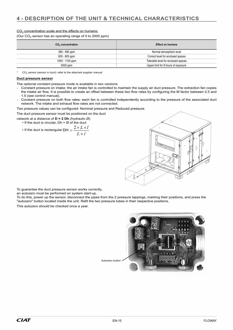
Two pressure values can be configured: Nominal pressure and Reduced pressure.The duct pressure sensor must be positioned on the duct network at a distance of D = 2 Dh (hydraulic Ø)
• If the duct is circular, Dh = Ø of the duct
• If the duct is rectangular DH
To guarantee the duct pressure sensor works correctly,an autozero must be performed on system start-up. To do this, power up the sensor, disconnect the pipes from the 2 pressure tappings, marking their positions, and press the"autozero" button located inside the unit. Refit the two pressure tubes in their respective positions.This autozero should be checked once a year.
Autozero button
4 - DESCRIPTION OF THE UNIT & TECHNICAL CHARACTERISTICS
EN-15 FLOWAY

Changeover thermostat for mixed coilThe customer is responsible for installation on the hydraulic system.The Changeover thermostat installed on the pipe must be integrated into the hydraulic pipe insulation
Technical characteristicsMin. WINTER temp.: 28 °CMin. SUMMER temp.: 18 °CBreaking capacity: 5(3) A.Cable length: 2500 mm
29
Ø 1/2" or 7/8"
21
BLACK wire (winter)IVORY wire (shared)
BLUE wire (do not use)
Damper
The damper is not protected against the weather if the canopy option has not been selected.
4 - DESCRIPTION OF THE UNIT & TECHNICAL CHARACTERISTICS
FLOWAY EN-16

5 - INSTALLATION AND INSTALLATION CONNECTIONS
The installation of the equipment must comply with the regulations and standards of the recipient countryThe additional box must be positioned in the duct so that the temperature sensor is on the downstream side (air supply)
Special recommendations:• Connections must not place mechanical stresses on the unit.• Keep all inspection doors closed while the unit is operating• If fitted outdoors (Classic PHE and Classic RHE/RHE-Z models only), the units must be installed so as to withstand the climatic
conditions in the installation location (risk of snow: height from ground/risk of wind: suitable mountings, swan-neck type electrical connection to the unit etc.).
Flexible sleeve
Ensure all electrical components are earthed.
5.1 - OUTDOOR INSTALLATION ("Classic PHE" and "Classic RHE/RHE-Z" model only)
The installation of a "Floway" dual-flow unit outdoors requires a roof and a canopy to be fitted; these are usually supplied mounted* and adapted to suit each configuration.(* Supplied in kit form if delivery of the elements assembled is not possible)
Fitting the roofs:The roofs for Floway units are designed to provide sufficient protection against adverse weather conditions, as they overlap the edge of the unit by 80 mm.
Fitting procedure:
1 Fix the foam seal along the length of the unit. (50 x 20 foam seal).2 Fix the roof panel(s) along the entire length of the unit.
50x20 foam gasket bonded for roof curvature
3 Assemble the roof on the unit as per the following diagram
Ø 4.8 self-drilling screw
Roof
Side rail
Ø 22.2 blanking cover Ø 4.8 sealed rivet or Ø 4.2 self-drilling screw + sealed washer
EN-17 FLOWAY

5.2 - FLOWAY RHEZ 10000 & 15000 : PROCEDURE FOR ROOF ASSEMBLY
■ The Floway RHEZ 10000 & 15000 are delivered in two blocks: a Wheel Block & an FMA Block, with a roof attached to each block ■ Procedure for assembling the roof
1. Remove the roof from the Wheel block (retaining the screw and cap)2. Assemble the blocks3. Reposition the roof from the Wheel Block, taking care to ensure the roofs interleave correctly4. Secure the roof to the block
Delivery of two separate blocks: WHEEL Block + FMA Block
Removal of the WHEEL Block roof
5 – INSTALLATION AND INSTALLATION CONNECTIONS
FLOWAY EN-18

Removal of the WHEEL Block roof
Refitting of the WHEEL Block roof
5 – INSTALLATION AND INSTALLATION CONNECTIONS
EN-19 FLOWAY

Assembly of the two Blocks with their roofs
5 – INSTALLATION AND INSTALLATION CONNECTIONS
FLOWAY EN-20

Fitting the Canopy without damper:The upper panel will be assembled on the two side panels using screws, washers and nuts or sealed rivets. Also fit the protective screen during assembly, either on the damper or on the panel, as applicable (see illustrations)
sealed rivet
Canopy without damperCanopy with damper
Screen
Screen
11 202011
N x
E
AD
M x FØ 6
Screen
Classic RHE /RHEZ A B C C2 D N x E M x F Weight (kg)
1000 687 274 329,5 311 650 2X135 - 2,52000 787 304 429 411 750,5 2X185 - 3,43000 1189 358 580 562 1152 2X260 3X340 5,44000 / 5000 1489 390 670 652 1452 2X305 6X220 76000 / 7500 / 10000 1789 528 860 842 1752 2X400 5X324 12,215000 2050 428 870 851 2013 2X400 6X324 10
5 – INSTALLATION AND INSTALLATION CONNECTIONS
EN-21 FLOWAY

Flexible sleeve :
COMPOSITION of a flexible sleeve package : - 1 sewn sleeve casing - 8 strips to be assembled
(4 widthways + 4 lengthways)
1 Insert the strips into the hems of the sleeve, checking to ensure the holes are aligned:
2 Assemble the strips together, first identifying the two lengthways strips and the two widthways strips. Fit them together and strike in turn to seat / Proceed in the same manner for the two sides of the sleeve:
3 Fitting on the machine with screws and washers:
5 – INSTALLATION AND INSTALLATION CONNECTIONS
FLOWAY EN-22
CONNECTIONSDIMENSIONS OF AIR FLOW CIRCUITS
Floway “Classic PHE” and “Classic RHE/RHE-Z”
Sizes
1000 2000 3000 4000 / 5000 6000 / 7500 10 000 15 000Connections (mm) air intake and discharge* 201x502 301x601 458x984 608x1284 758x1584 797x1577 807x1907
* Internal dimensions
Vertical FLOWAY PHE
Sizes
700 1200 1600
Ø Connections (mm)Inlet air 2x160 2x250 2x250Air discharge 315 355 400
* Internal dimensions
Additional box
Sizes
1 2 3 4 5
Connections (mm)Inlet air 201x502 301x601 458x984 608x1284 758x1584Air discharge 201x502 301x601 458x984 608x1284 758x1584
* Internal dimensions
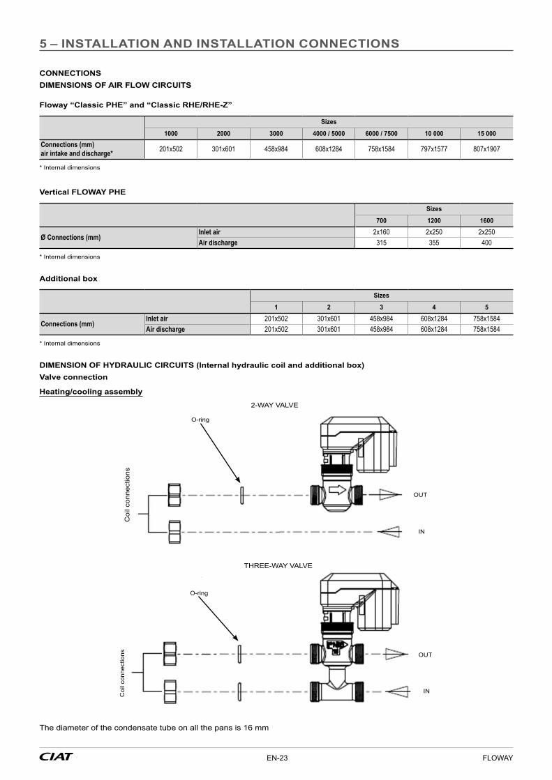
DIMENSION OF HYDRAULIC CIRCUITS (Internal hydraulic coil and additional box)Valve connection
Heating/cooling assembly
Coi
l con
nect
ions
2-WAY VALVE
OUT
IN
O-ring
THREE-WAY VALVE
OUT
INCoi
l con
nect
ions
O-ring
The diameter of the condensate tube on all the pans is 16 mm
5 – INSTALLATION AND INSTALLATION CONNECTIONS
EN-23 FLOWAY
FLOWAY “Classic PHE” and "Classic RHE/RHE-Z"
Sizes
1000 2000 3000 4000 5000 6000 7500 10 000 2 rows
15 000 2 rows
Ø connections (mm) 4-way valve
inlet G 1/2" G 1/2" G 3/4" G 3/4" G 3/4" G 1" G 1" G 1"1/2 G 1"1/2outlet (on valve) G 1/2" G 1/2" G 3/4" G 3/4" G 3/4" G 1"1/2 G 1"1/2 Rp 1"1/4 Rp 1"1/4
Sizes10 0004 rows
15 0004 rows
Ø connections (mm) 3-way valveinlet G2" G2"outlet (on valve) Rp 1"1/2 Rp 1"1/2
sVertical FLOWAY PHE
Sizes
700 1500 2000
Ø connections (mm) 4-way valveValve inlet G 1/2" G 1/2" G 1/2"Valve outlet G 1/2" G 1/2" G 1/2"
ELECTRICAL CONNECTIONS
FLOWAY “Classic PHE” and "Classic RHE/RHE-Z"
Sizes
1000 2000 3000 4000 5000 6000 7500 10000 15000
Supply type 1~230 V - 50 Hz 3~400 V - 50 Hz
Nominal current without internal electric heater (A) 5,8 4,2 7 8,6 8,6 10 10 19 24,6Minimum power supply cable section without electric heater* 1,5 mm² 1,5 mm² 1,5 mm² 1,5 mm² 1,5 mm² 1,5 mm² 1,5 mm² 2,5 mm² 2,5 mm²
Disconnect switch size OT40(40A)Nominal current with internal electric heater (A) 25,4 19,8 25,2 32,8 37,2 42,9 55 91,2 118,4Minimum power supply cable section with electric heater* 2,5 mm² 2,5 mm² 2,5 mm² 4 mm² 6 mm² 6 mm² 10 mm² 25 mm² 35 mm²
Disconnect switch size OT40 (40 A) OT40 (40 A)
OT40 (40 A)
OT63 (63 A)
OT63 (63 A)
OT63 (63 A)
OT80 (80 A)
OT100 (100 A)
OT125 (125 A)
Max. terminal section (mm²) 10 mm² 10 mm² 10 mm² 35 mm² 35 mm² 35 mm² 35 mm² 70 mm² 70 mm²Torque Value (N.m) 0,8 Nm 0,8 Nm 0,8 Nm 2 Nm 2 Nm 2 Nm 2 Nm 6 Nm 6 Nm
Vertical FLOWAY PHE
Sizes
700 1500 2000Supply type 1~230 V - 50 Hz 3~400 V - 50 HzNominal current without internal electric heater (A) 6,2 4,2 4,2Minimum power supply cable section without electric heater* 1,5 mm² 1,5 mm² 1,5 mm² Nominal current with internal electric heater (A) 25,8 15,9 19,8Minimum power supply cable section with electric heater* 2,5 mm² 1,5 mm² 2,5 mm² Disconnect switch size OT40 (40 A) OT40 (40 A) OT40 (40 A)Max. terminal section (mm²) 10 mm² 10 mm² 10 mm² Torque Value (N.m) 0,8 Nm 0,8 Nm 0,8 Nm
* The minimum cable sections are given as a guideline for a JZ type cable at 30 °C in the open air (outside the duct).These sections must be calculated taking into account the specifications of each installation (type of fitting, ambient temperature, cable length etc.)
5 – INSTALLATION AND INSTALLATION CONNECTIONS
FLOWAY EN-24

Additional electrical heater box
Sizes
1 2 2 3 4 4 5 5
Associated model
Classic PHE/RHE/RHEZ 1000
Vertical PHE 700Vertical PHE 1500
Classic PHE/RHE/RHEZ 2000
Vertical PHE 2000
Classic PHE/RHE/RHEZ3000
Classic PHE/RHE/RHEZ4000
Classic PHE/RHE/RHEZ5000
Classic PHE/RHE/RHEZ6000
Classic PHE/RHE/RHEZ7500
Voltage 230 V 1-Ph 400 V 3-PhCurrent 19,6 10,4 15,6 18,2 24,2 28,6 32,9 45
Requires a specific dedicated power supplyConnect the unit's electrics to the power network as per the tables above. Connection to the main circuit breaker located inside the box (Ø 22.2 blanking cover provided).If there is an electric heater in the additional box, make provision for the electrical connections.
Sizes
1000 2000 3000 5000 7500Voltage (V) 230 V 1-Ph 400 V 3-PhMax. current (A) 5,4 3,6 6,1 8,8 10,3Minimum power supply cable section 3G1 4G0.75 4G1 4G1.5 4G1.5Disconnect switch size OT40 (40 A) OT63 (63 A)Max. terminal section (mm2) 0,75 to 10 1,5 to 35Torque Value (N.m) 0,8 2
• Connect the unit's electrics to the power network as per the table above.• Connection to the machine's general disconnect switch located inside it (Ø 22.2 blanking cover provided).• For sections between 0.75 and 2.5 mm2, a H 05 VV-F type cable may be used, otherwise the cable must be type H 07 RN-F.• The power supply cable must be sized in accordance with current standards and regulations.• The supply cable must be secured using the anchorage provided (located between the disconnect switch and the Ø 22.2
blanking cover). Once the supply cable has been fed through and connect, tighten the clamp fully and cut the end extending past the clamp.
• Respect the current assigned to the disconnect switch for the air handling unit.• The leakage current may reach 13 mA. Earthing is essential. Each unit is equipped with 2 earth terminals (PE) indicated by
the logo , one close to the disconnect switch, and the other on one of the unit's feet. Both terminals must be permanently connected.
Ø 22.2 blanking cover
Anchorage
Earth terminals
Disconnectswitch
5 – INSTALLATION AND INSTALLATION CONNECTIONS
EN-25 FLOWAY

Identification of terminal strip options for the Classic RHE/RHE-Z, CLASSIC PHE and VERTICAL PHE models.
AHU operating feedback
Setpoint 1/Setpoint 2 selection
Intake duct pressure sensor or air quality sensor
Remote control
24V fresh air/exit air dampers control
24V supply air/return air dampers control
0 -10V valve 1 control0 -10V valve 2 control
Valves 24V supply
Changeover thermostat
Pump 2 monitoring
Pump 1 control
Pump 2 control
Electric heater stage 1 control
Intake air duct temperature sensor
Pump 1 monitoring
Danger fault feedback shared fault feedback maintenance fault feedback
Wire references
Boiler ON command
Electric heater stage 2 control or preheating coil
Electric heater stage 2 safety monitoring or preheating coil
Fire detection
Coil stage 1 safety monitoring
NB: the maximum cross-section of the stripped wire is Ø 1.5 mm and Ø 0.5 mm for wire with an end-piece.
5 – INSTALLATION AND INSTALLATION CONNECTIONS
FLOWAY EN-26

Additional box terminal block references
Hydraulic coil valve control
Remote temperature sensor
Electric heater safety monitoring
Electric heater stage 2 controlElectric heater stage 1 control
Electric heaters ► Pre-heats 1 stage: 4 wires
Machine terminal block Additional box terminal block Notes Inlet/Outlet
Xm 22 _ b-3 Xm 7 _ b-1 On/off control24 VAC Digital outputs
Xm 22 _ b-4 Xm 7 _ b-2Xm 22 _ b-7 Xm 7 _ b-4 Electric heater safety thermostat return
Dry contact Digital inputsXm 22 _ b-8 Xm 7 _ b-5
Remote temperature sensor not connected if there is a pre-heating coil ► Pre-heating 1 stage + post-heating 1 stage: 4 + 6 wires
Machine terminal block Additional box terminal block Pre-heating
Additional box terminal block Post-heating Notes Inlet/Outlet
Xm 22 _ b-1 Xm 7 _ b-1 Post-heating ON/OFF control (24 VAC)
Digital outputsXm 22 _ b-2 Xm 7 _ b-2Xm 22 _ b-3 Xm 7 _ b-1 Pre-heating ON/OFF control
(24 VAC)Xm 22 _ b-4 Xm 7 _ b-2Xm 22 _ b-5 Xm 7 _ b-4 Post-heating safety thermostats return
Dry contactDigital inputs
Xm 22 _ b-6 Xm 7 _ b-5Xm 22 _ b-7 Xm 7 _ b-4 Pre-heating safety thermostats return
Dry contactXm 22 _ b-8 Xm 7 _ b-5Xm 20 _ b-7 Xm 7 _ b-6 Intake air duct temperature sensor
NTC10k Analogue inputXm 20 _ b-8 Xm 7 _ b-7
5 – INSTALLATION AND INSTALLATION CONNECTIONS
EN-27 FLOWAY

► Post-heating 1 stage: 6 wires
Machine terminal block Additional box terminal block Notes Inlet/Outlet
Xm 22 _ b-1 Xm 7 _ b-1 On/off control24 VAC Digital outputs
Xm 22 _ b-2 Xm 7 _ b-2Xm 22 _ b-5 Xm 7 _ b-4 Electric heater safety thermostat return
Dry contact Digital inputsXm 22 _ b-6 Xm 7 _ b-5Xm 20 _ b-7 Xm 7 _ b-6 Intake air duct temperature sensor
NTC10k Analogue inputsXm 20 _ b-8 Xm 7 _ b-7
► Post-heating 2 stages: 8 wires
Machine terminal block Additional box terminal block Notes Inlet/Outlet
Xm 22 _ b-1 Xm 7 _ b-1 On/off control stage 124 VAC
Digital outputsXm 22 _ b-2 Xm 7 _ b-2Xm 22 _ b-3 Xm 7 _ b-3 On/off control stage 2
24 VACXm 22 _ b-4 Xm 7 _ b-2Xm 22 _ b-5 Xm 7 _ b-4
Electric heater safety thermostat return Digital inputsXm 22 _ b-6 Xm 7 _ b-5Xm 20 _ b-7 Xm 7 _ b-6
Intake air duct temperature sensor NTC10k Analogue inputsXm 20 _ b-8 Xm 7 _ b-7
Hydraulic coil ► Hydraulic 1: 5 wires
Machine terminal block Additional box terminal block Notes Inlet/Outlet
Xm 20 _ b-1 Xm 7 _ b-12 0 -10V coil valve control 1 Analogue outputXm 20 _ b-3 Xm 7 _ b-10
24-V valve supplyXm 20 _ b-4 Xm 7 _ b-11Xm 20 _ b-7 Xm 7 _ b-6
"Intake air duct temperature sensor NTC10k" Analogue inputXm 20 _ b-8 Xm 7 _ b-7
► Hydraulic 2: 5 wires
Machine terminal block Additional box terminal block Notes Inlet/Outlet
Xm 20 _ b-2 Xm 7 _ b-12 0 -10V coil valve control 2 Analogue inputsXm 20 _ b-3 Xm 7 _ b-10
24-V valve supplyXm 20 _ b-4 Xm 7 _ b-11Xm 20 _ b-7 Xm 7 _ b-6
Intake air duct temperature sensor NTC10k Analogue outputXm 20 _ b-8 Xm 7 _ b-7
If there are several coils in the additional box, only connect the "last" temperature sensor to the air supply. ► Presence of changeover coil: 2 wires
Machine terminal block Notes Inlet/Outlet
Xm 20 _ b-5 C/O thermostat black wireDigital inputs
Xm 20 _ b-6 C/O thermostat white wire
The changeover thermostat must be positioned on the "customer" hydraulic pipe, on the "fluid entering the coil" side (so as to be in the insulation).Contact open: normal operation in cooling modeContact closed: operation in heating mode (contact closed from 28 °C)If the unit is equipped with an internal hydraulic coil, coil no. 2 in the additional box must be connected to the fast-on connectors provided for this purpose. (see additional box terminal block references)
5 – INSTALLATION AND INSTALLATION CONNECTIONS
FLOWAY EN-28

► External generator: 2 wires (Choice: heating or cooling)
Machine terminal block Notes Inlet/Outlet
Xm 21 _ b-9 On/off control24 VAC Digital inputs
Xm 21 _ b-10
The ON command is given when the heating/cooling demand is true ► Supply air and return air damper control: 2 wires
Machine terminal block Notes Inlet/Outlet
Xm 19 _ b-1 Damper opening/closing control24 VAC Digital output
Xm 19 _ b-2
► Fresh air and exit air dampers control: 2 wires
Machine terminal block Notes Inlet/Outlet
Xm 19 _ b-3 Damper opening/closing control24 VAC Digital output
Xm 19 _ b-4
Relay closed = Damper open (relay normally closed)Relay opened = Damper closed
► Fire detection: 2 wires
Machine terminal block Notes Inlet/Outlet
Xm 22 _ b-9 Fire detection activationDry contact Digital inputs
Xm 22 _ b-10
Contact normally closed ► AHU operating feedback
Machine terminal block Notes Inlet/Outlet
Xm 18 _ b-1 AHU operating feedback Dry contact Digital output
Xm 18 _ b-2
► Pump 1 monitoring: 4 wires
Machine terminal block Notes Inlet/Outlet
Xm 21 _ b-5 ON command Pump 124V AC Digital inputs
Xm 21 _ b-6Xm 21 _ b-1 Pump 1 fault monitoring
Contact sec Digital inputsXm 21 _ b-2
Pump 1 ON command if Hydraulic coil 1 operating orderAs Xm21 B5-6 is 24 VAC polarised on the Pump1 ON command, provide a 24 VAC relay (50/60 Hz, max 0.75 VA; not supplied by CIAT)
► Pump 2 monitoring: 4 wires
Machine terminal block Notes Inlet/Outlet
Xm 21 _ b-7 ON command Pump 224V AC Digital inputs
Xm 21 _ b-8Xm 21 _ b-3 Pump 2 fault monitoring
Contact sec Digital inputsXm 21 _ b-4
Pump 2 ON command if Hydraulic coil 2 operating orderAs Xm21 B7-8 is 24 VAC polarised on the Pump2 ON command, provide a 24 VAC relay (50/60 Hz, max 0.75 VA; not supplied by CIAT)
5 – INSTALLATION AND INSTALLATION CONNECTIONS
EN-29 FLOWAY

► Remote On/Off: 2 wires
Machine terminal block Notes Inlet/Outlet
Xm 18 _ b-8 Unit ON/OFF monitoringDry contact Digital inputs
Xm 18 _ b-9
► Setpoint 1/setpoint 2 selection: 2 wires
Machine terminal block Notes Inlet/Outlet
Xm 18 _ b-6Dry-contact setpoint selection Digital output
Xm 18 _ b-7
► Air quality sensor: 3 wires
Machine terminal block Notes Inlet/Outlet
Xm 19 _ b-5 SharedXm 19 _ b-6 Sensor 24V supply
Xm 19 _ b-7 CO2 sensor/transmitter 0-10 V active rear sensor Analogue input
► Fault feedback: 4 wires
Machine terminal block Notes Inlet/Outlet
Xm 18 _ b-3 "Danger" fault monitoringDry contact (shared b-4)
Digital outputsXm 18 _ b-4 Shared
Xm 18 _ b-5 "Maintenance" fault monitoringDry contact (shared b-4)
► Intake duct pressure sensor: 3 wires
Machine terminal block Notes Inlet/Outlet
Xm 19 _ b-5 SharedXm 19 _ b-6 (IN) sensor 24V supply
Xm 19 _ b-7 (OUT) pressure monitoring signal 0-10 V Analogue input
INSTALLING THE SIPHON ON CONDENSATE DRAINS
It is important to ensure the siphon is correctly fitted, as per the diagram below. For a depression H in the condensate drain, the sizing of the siphon must incorporate dimensions of 2H.Schematic diagram of siphon
Vco2 GND
Power supply 24 VDC
Controller display or passive controller
0-10 V output
3-wire tech.
IN
OUT
GND
3
2
1
5 – INSTALLATION AND INSTALLATION CONNECTIONS
FLOWAY EN-30

Assembly with depression :Z: X+Y+tubing diameter + insulation thicknessY: Y = 0.5 * XX: X = 25 mm for each 250 Pa of negative static pressure + 25 mm
Slight slope of 0.005
Negative pressure recovery pan
To sewer system
mmWC
Z (m
m)
Y (m
m)
X (m
m)
Assembly with pressure:X = 12 mmY = 12 mm + total static pressure (1 mm for 10 Pa)
X
Y
NB: the condensate pan on the heat recovery unit is pressurised on the “Vertical PHE" model, and is also pressurised if there is a cooling or mixed coil in the additional casing.
5.3 - FLOWAY CLASSIC RHEZ / VERIFICATION OF PRESSURES
Verification of the pressures for EATR limitation : - The limitation of the EATR value depends on the size of the installation and, specifically, the pressure drop on the exhaust air
duct - The presence of a manual control damper may however prove necessary to balance these pressures correctly (damper not
supplied by CIAT): contact the installation's design engineer - This verification is used to adjust the installation so that any inclusion of exhaust air in the fresh air during recirculation is avoided - The Floway Cassic RHE-Z is equipped with pressure connections P11 and P22 for diagnostics as follows:
∆P 2
2 x
11 >
0
22
11
ETA
SUP
Exhaust air
Fresh air
P22
Pressure connection
P11
5 – INSTALLATION AND INSTALLATION CONNECTIONS
EN-31 FLOWAY

- This translates as ΔP22-11 > 0 (for example: P22 = -300 Pa → P11 = -350 Pa) - Ideally, the minimum value between P22 and P11 should be 20 Pa - The pressure should be lower at P11 as per the above; if not the case, adjust the damper or dampers present in the return air duct
5.4 - MAINTENANCE / SPACE IN FRONT OF THE UNITS
Ideally, for all simple and complex maintenance work (removal of the exchanger, coils, etc.),sufficient free space sshould be left at the front to perform these operations:L = machine lengthH = operator height for small models / machine height for Sizes > 6000
1000 2000 3000 4000/5000 6000/7500 10000 15000
l 700 900 1100 1400 1700 1800 2100
5 – INSTALLATION AND INSTALLATION CONNECTIONS
6 - SYSTEM START-UP
Commissioning must be performed by qualified personnel, trained in air handling technology. Keep all inspection doors closed while the unit is operating.
Once the electrical and hydraulic connections have been finished, the commissioning of the unit can proceed, checking the steps below: - Check the tightness of all connections, - Make sure that the inside of the unit is clean, and that there are no foreign bodies inside it, - Check the wiring - Check the electrical supply voltage and the ratings of the overload protections against the current ratings of each component, - To configure the setpoints, refer to the corresponding manual (N09.61), - Simulate activation of the various electric components, controlled components and alarms, - Check the currents:
• Temperature alarm,• Air flow alarm,• Fan motor assembly
- Check the air flow rates - After a few hours' operation, check the filter fouling condition.
REGULATION: FLOWAY CONTROLTo set and configure the "Floway Control", refer to the corresponding manual (no. 7565703).
FLOWAY EN-32

7 - MAINTENANCE/SERVICE INTERVALS
Switch off the electrical supply to the air handling unit before carrying out any work
Details of hinges/handles: Allen key locks, size 4When they are unlocked, the handles are in "hinge" mode. It is possible to unlock a single row of handles to open like a conventional door. If all of the handles are unlocked, the door can be removed.
Handle locked
Handle unlocked
Door
7.1 - FILTERS
After commissioning, the speed of filter fouling will depend on the care taken when cleaning the air flow circuits. Hence the frequency of filter checks should be increased during this period.
Maintenance intervalsThe filter life depends essentially on the amount of dust in the air and the efficiency of the filtration system. The filtration quality cannot be maintained if the filter medium has been damaged during maintenance. We recommend that the filters be replaced once every two years, even in the case of moderate use
Filter replacement methodDuring filter maintenance operations, it is important not to spread the dust that has accumulated in the filters. Shut down the unit,Access the filters by opening the door panels,Simply pull on the filters Pull the connecting runner (on Floway Classic PHE and RHE/RHE-Z ≥ 3000 m3/h models), then you can remove the filters. For the other models, simply pull directly on the filters.
Example: Floway "Classic PHE"
Connecting runner
Filter
EN-33 FLOWAY

7.2 - FAN MOTOR ASSEMBLY
Check and retighten the electrical connections once a year.
Removing the fanOpen the door as explained above, Unlock the 4 x M8 screws using the ratchet wrench and its extension,Disconnect the motor's electrical connections,Remove the fan via the access door.
Example: Floway "Classic PHE"
7.3 - HEAT RECOVERY UNIT
Plate heat exchanger ("Ceiling PHE", "Vertical PHE" and "Classic PHE" models)Schedule annual dust removal / degreasing and maintenance of the bypass damper.It is important to remember to clean and degrease the condensate drain pan using water and non-abrasive detergents: The heat recovery unit on the "Vertical PHE" model is accessible via the door and can be removed by the sliding runner.
Rotary heat exchangers (“Classic RHE/RHE-Z” model)Check the maximum and minimum rotation speeds once a year.When stationary, the rotary heat exchangers accumulate dust and moisture at their lowest point. Schedule cleaning during prolonged stoppages. Check the permanently lubricated bearings once a year.
Heat recovery unit drive unit consumption
Sizes
1000 2000 3000 4000 5000 6000 7500 10 000 15 000
Variable speedMax. power (W) 110 110 110 110 110 110 240 240 240Voltage (V) 1 x 230 V
7.4 - ELECTRICS BOX
Retighten the connections twice a year.Visually inspect the components, wires and cables.
7 - MAINTENANCE/SERVICE INTERVALS
FLOWAY EN-34

7.5 - ELECTRIC HEATERS
The electric heater requires very little maintenance. However, the following checks are necessary:Visually inspect the heating elements, wires and connection cables after every 1500 hours of operation.Check and retighten the connections once or twice a year.
7.6 - HYDRAULIC COILS
The hydraulic coil requires very little maintenance as it is protected by the filter.
7.7 - SERVICE INTERVALS
Regular maintenance will keep the unit running at optimum performance. The values given in the table below are provided for guidance only. They do not take into account individual factors that can lengthen or shorten the unit's service life.
7 - MAINTENANCE/SERVICE INTERVALS
8 - PROBLEMS/CAUSES/SOLUTIONS
Refer to the "Floway Control" control manual N09.61.
Components At commissioning 2 to 3 months 12 months Operating readings
Filters Check the fouling level and replace if necessary Replace
Fans Check the connections Retighten the connections
Electrics box Check the connections Operating checkRetighten the electrical connectionsCheck the componentsOperating check
Pressure/temperature sensor Check correct operation and setpoint adjustment
Check correct operation and setpoint adjustment
Check correct operation and setpoint adjustment
Condensate pan Clean with water and a non-abrasive detergent
Clean with water and a non-abrasive detergent
9 - TESTS AND GUARANTEES
To guarantee the product's quality, each Floway air handling unit undergoes a variety of tests: EMC (electromagnetic compatibility) test, component functional tests (fan motor assembly, heat recovery unit, sensor, etc.).However, our units are guaranteed for a period of 12 months from the commissioning date, when this date occurs within three months of the invoice date. It is effective for a period of 15 months from the unit invoice date in all other cases.
CIAT's guarantee on motors is limited to the terms of guarantee extended by its supplier. Under no circumstances must the fitter carry out work on the motor. This will invalidate any future claims on the warranty.
NB: for more information, refer to the application of the CIAT warranty.
EN-35 FLOWAY

Manufacturer: CIAT S.A, Culoz, France. Printed in the European Union.Manufacturer reserves the right to change any product specifications without notice.