11-66. general. table 11-6. tabulation chart …not2fast.com/fabrication/wiring/3u-ch11_5.pdf · ac...
TRANSCRIPT

9/8/98 AC 43.13-1B
Par 11-66 Page 11-21
SECTION 5. ELECTRICAL WIRE RATING
11-66. GENERAL. Wires must be sized sothat they: have sufficient mechanical strength toallow for service conditions; do not exceed al-lowable voltage drop levels; are protected bysystem circuit protection devices; and meet cir-cuit current carrying requirements.
a. Mechanical Strength of Wires. If it isdesirable to use wire sizes smaller than #20,particular attention should be given to the me-chanical strength and installation handling ofthese wires, e.g., vibration, flexing, and termi-nation. Wire containing less than 19 strandsmust not be used. Consideration should begiven to the use of high-strength alloy con-ductors in small gauge wires to increase me-chanical strength. As a general practice, wiressmaller than size #20 should be provided withadditional clamps and be grouped with at leastthree other wires. They should also have addi-tional support at terminations, such as con-nector grommets, strain relief clamps, shrink-able sleeving, or telescoping bushings. Theyshould not be used in applications where theywill be subjected to excessive vibration, re-peated bending, or frequent disconnection fromscrew termination.
b. Voltage Drop in Wires. The voltagedrop in the main power wires from the genera-tion source or the battery to the bus should notexceed 2 percent of the regulated voltage whenthe generator is carrying rated current or thebattery is being discharged at the 5-minute rate.The tabulation shown in table 11-6 defines themaximum acceptable voltage drop in the loadcircuits between the bus and the utilizationequipment ground.
c. Resistance. The resistance of the cur-rent return path through the aircraft structure isgenerally considered negligible. However, thisis based on the assumption that adequate
TABLE 11-6. Tabulation chart (allowable voltage dropbetween bus and utilization equipment ground).
Nominalsystemvoltage
Allowable voltagedrop continuous
operation
Intermittentoperation
1228115200
0.5147
12814
bonding to the structure or a special electriccurrent return path has been provided that iscapable of carrying the required electric currentwith a negligible voltage drop. To determinecircuit resistance check the voltage drop acrossthe circuit. If the voltage drop does not exceedthe limit established by the aircraft or productmanufacturer, the resistance value for the cir-cuit may be considered satisfactory. Whenchecking a circuit, the input voltage should bemaintained at a constant value. Tables 11-7and 11-8 show formulas that may be used todetermine electrical resistance in wires andsome typical examples.
d. Resistance Calculation Methods.Figures 11-2 and 11-3 provide a convenientmeans of calculating maximum wire length forthe given circuit current.
(1) Values in tables 11-7 and 11-8 arefor tin-plated copper conductor wires. Be-cause the resistance of tin-plated wire isslightly higher than that of nickel or silver-plated wire, maximum run lengths determinedfrom these charts will be slightly less than theallowable limits for nickel or silver-plated cop-per wire and are therefore safe to use. Fig-ures 11-2 and 11-3 can be used to deriveslightly longer maximum run lengths for silveror nickel-plated wires by multiplying the maxi-mum run length by the ratio of resistance oftin-plated wire, divided by the resistance of sil-ver or nickel-plated wire.

AC 43.13-1B 9/8/98
Page 11-22 Par 11-66
TABLE 11-7. Examples of determining required wiresize using figure 11-2.
Voltagedrop
RunLengths
CircuitCurrent
Wiresizefromchart
Check-calculated
voltage drop =(Resistance/Ft) (Length)(Current) =
1 volt
0.5 volt
4 volt
7 volt
100 feet
50 feet
100 feet
100 feet
20amps
40amps
20amps
20amps
No. 6
No. 2
No. 12
No. 14See
Note 1
(.000445ohms/ft)
(100 ft)(20 amps)=
.89 volts
(.000183ohms/ft)(50 ft)
(40 amps)=.366 volts
(.00202ohms/ft)(100 ft)
(20 amps)=4.04 volts
(.00304ohms/ft)(100 ft)
(20 amps)=6.12 volts
Note #1: #14 Wire should be routed separately for this
current rating.
TABLE 11-8. Examples of determining maximum runlength using figure 11-3.
MaximumVoltage
drop
WireSize
CircuitCurrent
MaximumWire Run
Length
Check-calculatedvoltage drop =(Resistance/Ft)
(Length)(Current)=
1 volt
0.5 volt
4 volt
7 volt
No. 10
- - - -
- - - -
- - - -
20amps
- -
- -
- -
39 feet
19.5 feet
156 feet
273 feet
(.00126 ohms/ft)(39 ft)(20 amps)=
.98 volts
(.00126 ohms/ft)(19.5 ft) (20 amps)=
.366 volts
(.00126 ohms/ft)(156 ft) (20 amps)=
3.93 volts
(.00126 ohms/ft)(273 ft) (20 amps)=
6.88 volts
(2) As an alternative method or a meansof checking results from figure 11-2, resistancefor a given wire size can be read from ta-ble 11-9 and multiplied by wire run length andcircuit current.
(3) Voltage drop calculations for alumi-num wires can be accomplished by multiplyingthe resistance for a given wire size, defined intable 11-10, by the wire run length and circuitcurrent.
(4) When the estimated or measuredconductor temperature (T2) exceeds 20 °C,such as in areas having elevated ambient tem-peratures or in fully loaded power-feed wires,the maximum allowable run length (L2), mustbe shortened from L1 (the 20 °C value) usingthe following formula for copper conductorwire:
LC L
C T2
1
2
254 5
234 5=
°° +
( . )( )
( . ) ( )
For aluminum conductor wire, the formula is:
LC L
C T2
1
2
258 1
238 1=
°° +
( . )( )
( . ) ( )
These formulas use the reciprocal of each ma-terial’s resistivity temperature coefficient totake into account increased conductor resis-tance resulting from operation at elevated tem-peratures.
(5) To determine T2 for wires carrying ahigh percentage of their current carrying capa-bility at elevated temperatures, laboratorytesting using a load bank and a high-temperature chamber is recommended. Suchtests should be run at anticipated worse caseambient temperature and maximum current-loading combinations.
9/8/98 AC 43.13-1B
Par 11-66 Page 11-23
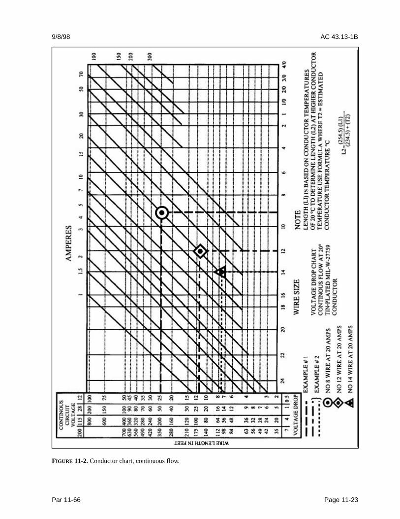
FIGURE 11-2. Conductor chart, continuous flow.

AC 43.13-1B 9/8/98
Page 11-24 Par 11-66
FIGURE 11-3. Conductor chart, intermittent flow.

9/8/98 AC 43.13-1B
Par 11-66 Page 11-25
TABLE 11-9. Current carrying capacity and resistance of copper wire.
WireSize
Continuous duty current (amps)-Wires in bundles,groups, harnesses, or conduits. (See Note #1)
Max. resistanceohms/1000ft@20°
C
Nominalconductor
Wire Conductor Temperature Rating tin plated conduc-tor
area -
105°C 150°C 200°C (See Note #2) circ.mils
2422201816141210864210
00000
0000
2.5346710131738506895113128147172204
4579111419265776103141166192222262310
56912141825327197
133179210243285335395
28.4016.209.886.234.813.062.021.260.700.440.280.180.150.120.090.070.06
475755
1,2161,9002,4263,8315,8749,35416,98326,81842,61566,50081,700
104,500133,000166,500210,900
Note #1: Rating is for 70°C ambient, 33 or more wires in the bundle for sizes 24 through 10, and 9wires for size 8 and larger, with no more than 20 percent of harness current carrying capacity beingused, at an operating altitude of 60,000 feet. For rating of wires under other conditions or configura-tions see paragraph 11-69.Note #2: For resistance of silver or nickel-plated conductors see wire specifications.
TABLE 11-10. Current carrying capacity and resistance of aluminum wire.
Wire SizeContinuous duty current (amps)Wires in bundles, groups or harnessesor conduits (See table 11-9 Note #1)
Max. resistanceohms/1000ft
Wire conductor temperature rating @20°C105°C 150°C
86421000
0000000
3040547690102117138163
456182113133153178209248
1.0930.6410.4270.2680.2140.1690.1330.1090.085
Note: Observe design practices described in paragraph 11-67 for aluminum conductor

AC 43.13-1B 9/8/98
Page 11-26 Par 11-66
(6) Approximate T2 can be estimatedusing the following formula:
T T T T I IR2 1 1= + −( )( / max2 )
Where:
T1 = Ambient Temperature
T2 = Estimated Conductor Temperature
TR= Conductor Temperature Rating
I2 = Circuit Current (A=Amps)
Imax = Maximum Allowable Current (A=Amps) at TR
This formula is quite conservative and willtypically yield somewhat higher estimated tem-peratures than are likely to be encountered un-der actual operating conditions.
11-67. METHODS FOR DETERMININGCURRENT CARRYING CAPACITY OFWIRES. This paragraph contains methods fordetermining the current carrying capacity ofelectrical wire, both as a single wire in free airand when bundled into a harness. It presentsderating factors for altitude correction and ex-amples showing how to use the graphical andtabular data provided for this purpose. Insome instances, the wire may be capable of car-rying more current than is recommended forthe contacts of the related connector. In thisinstance, it is the contact rating that dictatesthe maximum current to be carried by a wire.Wires of larger gauge may need to be used tofit within the crimp range of connector contactsthat are adequately rated for the current beingcarried. Figure 11-5 gives a family of curveswhereby the bundle derating factor may beobtained.
a. Effects of Heat Aging on Wire Insula-tion. Since electrical wire may be installed inareas where inspection is infrequent over ex-tended periods of time, it is necessary to givespecial consideration to heat-aging characteris-tics in the selection of wire. Resistance to heatis of primary importance in the selection ofwire for aircraft use, as it is the basic factor inwire rating. Where wire may be required tooperate at higher temperatures due either tohigh ambient temperatures, high-current load-ing, or a combination of the two, selectionshould be made on the basis of satisfactoryperformance under the most severe operatingconditions.
b. Maximum Operating Temperature.The current that causes a temperature steadystate condition equal to the rated temperatureof the wire should not be exceeded. Ratedtemperature of the wire may be based upon theability of either the conductor or the insulationto withstand continuous operation withoutdegradation.
c. Single Wire in Free Air. Determininga wiring system’s current carrying capacity be-gins with determining the maximum currentthat a given-sized wire can carry without ex-ceeding the allowable temperature difference(wire rating minus ambient °C). The curvesare based upon a single copper wire in free air.(See figures 11-4a and 11-4b.)
d. Wires in a Harness. When wires arebundled into harnesses, the current derived fora single wire must be reduced as shown in fig-ure 11-5. The amount of current derating is afunction of the number of wires in the bundleand the percentage of the total wire bundle ca-pacity that is being used.

9/8/98 AC 43.13-1B
Par 11-67 Page 11-27
e. Harness at Altitude. Since heat lossfrom the bundle is reduced with increased alti-tude, the amount of current should be de-rated.Figure 11-6 gives a curve whereby the altitudederating factor may be obtained.
f. Aluminum Conductor Wire. Whenaluminum conductor wire is used, sizes shouldbe selected on the basis of current ratingsshown in table 11-10. The use of sizes smallerthan #8 is discouraged. Aluminum wire shouldnot be attached to engine mounted accessoriesor used in areas having corrosive fumes, severevibration, mechanical stresses, or where thereis a need for frequent disconnection. Use ofaluminum wire is also discouraged for runs ofless than three feet. Termination hardwareshould be of the type specifically designed foruse with aluminum conductor wiring.
11-68. INSTRUCTIONS FOR USE OFELECTRICAL WIRE CHART.
a. Correct Size. To select the correct sizeof electrical wire, two major requirements mustbe met:
(1) The wire size should be sufficient toprevent an excessive voltage drop while carry-ing the required current over the required dis-tance. (See table 11-6, Tabulation Chart, forallowable voltage drops.)
(2) The size should be sufficient to pre-vent overheating of the wire carrying the re-quired current. (See paragraph 11-69 for al-lowable current carrying calculation methods.)
b. Two Requirements. To meet the tworequirements (see paragraph 11-66b) in select-ing the correct wire size using figure 11-2 orfigure 11-3, the following must be known:
(1) The wire length in feet.
(2) The number of amperes of current tobe carried.
(3) The allowable voltage droppermitted.
(4) The required continuous or inter-mittent current.
(5) The estimated or measured con-ductor temperature.
(6) Is the wire to be installed in conduitand/or bundle?
(7) Is the wire to be installed as a singlewire in free air?
c. Example No. 1. Find the wire size infigure 11-2 using the following known infor-mation:
(1) The wire run is 50 feet long, includ-ing the ground wire.
(2) Current load is 20 amps.
(3) The voltage source is 28 volts frombus to equipment.
(4) The circuit has continuous opera-tion.
(5) Estimated conductor temperature is20 °C or less.
The scale on the left of the chart representsmaximum wire length in feet to prevent an ex-cessive voltage drop for a specified voltagesource system (e.g., 12V, 28V, 115V, 200V).This voltage is identified at the top of scale andthe corresponding voltage drop limit for con-tinuous operation at the bottom. The scale(slant lines) on top of the chart represents am-peres. The scale at the bottom of the chartrepresents wire gauge.
STEP 1: From the left scale find the wirelength, 50 feet under the 28V source column.
AC 43.13-1B 9/8/98
Page 11-28 Par 11-68
STEP 2: Follow the corresponding horizontalline to the right until it intersects the slantedline for the 20-amp load.
STEP 3: At this point, drop vertically to thebottom of the chart and select the next wiresize to the right. This is the smallest size wirethat can be used without exceeding the voltagedrop limit expressed at the bottom of the leftscale. This example is plotted on the wirechart, figure 11-2. Use figure 11-2 for con-tinuous flow and figure 11-3 for intermittentflow.
d. Procedures in Example No. 1. Theprocedures in example No. 1, para-graph 11-68c, can be used to find the wire sizefor any continuous or intermittent operation(maximum two minutes). Voltage (e.g.12 volts, 28 volts, 115 volts, 200 volts) as indi-cated on the left scale of the wire chart in fig-ure 11-2 and 11-3.
e. Example No. 2. Find the wire size re-quired to meet the allowable voltage drop intable 11-6 for a wire carrying current at an ele-vated conductor temperature using the follow-ing information:
(1) The wire run is 15 feet long, includ-ing the ground wire.
(2) Circuit current is 20 amps,continuous.
(3) The voltage source is 28 volts.
(4) The wire type used has a 200 °Cconductor rating and it is intended to use thisthermal rating to minimize the wire gauge. As-sume that the method described in para-graph 11-66d(6) was used and the minimumwire size to carry the required current is #14.
(5) Ambient temperature is 50 °C underhottest operating conditions.
STEP 1: Assuming that the recommendedload bank testing described in para-graph 11-66d(5) is unable to be conducted,then the estimated calculation methods outlinedin paragraph 11-66d(6) may be used to deter-mine the estimated maximum current (Imax).The #14 gauge wire mentioned above can carrythe required current at 50 °C ambient (allowingfor altitude and bundle derating ).
(6) Use figure 11-4a to calculate theImax a #14 gauge wire can carry.
(7) Find the temperature differences(Tr-Ta) = (200° C-50° C) = 150 °C.
(8) Follow the 150° C line to intersectwith #14 wire size and reads 47 Amps at bot-tom of chart (current amperes).
(9) Use figure 11-6, left side of chartreads 0.91 for 20,000 feet, multiple0.91 x 47 Amps = 42.77 Amps.
(10) Use figure 11-5, find the deratefactor for 8 wires in a bundle at 60 percent.First find the number of wires in the bundle (8)at bottom of graph and intersect with the60 percent curve meet. Read derating factor,(left side of graph) which is 0.6. Multiply0.6 x 42.77 Amps = 26 Amps.
T2 = estimated conductor temperature
T1 = 50 °C ambient temperature
TR = 200 °C maximum conductor rated temperature
I2 = 20 amps circuit current, continuous

9/8/98 AC 43.13-1B
Par 11-68 Page 11-29
FIGURE 11-4a. Single copper wire in free air.
Imax = 26 amps (this is the maximum currentthe #14 gauge wire could carry at 50 °Cambient
L1=15.5 feet maximum run length for size#14 wire carrying 20 amps from figure 11-2
STEP 2: From paragraph 11-66d (5) and (6),determine the T2 and the resultant maximumwire length when the increased resistance ofthe higher temperature conductor is taken intoaccount.
( )( )T T T T I IR2 1 1 2= + − / max
T2 = + −50 200 50 20 26o o oC C C A A( )( / = 50°C+(150°C)(.877)
T2 = 182°C
L =(254.5 C)(L )
(234.5 C) + (T )2
1
2
°
°
L2 = (254.5 C)(15.5Ft)
(234.5 C) + (182 C)
°° °
L2 = 9.5 ft

AC 43.13-1B 9/8/98
Page 11-30 Par 11-68
FIGURE 11-4b. Single copper wire in free air.
The size #14 wire selected using the methodsoutlined in paragraph 11-66d is too small tomeet the voltage drop limits from figure 11-2for a 15 feet long wire run.
STEP 3: Select the next larger wire (size #12)and repeat the calculations as follows:
L1=24 feet maximum run length for12 gauge wire carrying 20 amps from fig-ure 11-2
Imax = 34.4 amps (this is the maximum cur-rent the size #12 wire can carry at 50 °C ambi-ent using calculation methods outlined in para-graph 11-69)
T C + (200 C - 50 C) ( 20A / 34.4
C + (150 C)(.762) = 164.4 C
LC(L
C + (T
LC)(24ft)
(234.5 C) + (164.4 C)
LC)(24ft)
398.9ft
2
o o
2
o1
o2
2
o
o o
2
o
= =
=
=
= =
50
50
254 5
234 5
254 5
254 515 3
o o o
o
. )
. )
( .
( ..

9/8/98 AC 43.13-1B
Par 11-68 Page 11-31
FIGURE 11-5. Bundle derating curves.

AC 43.13-1B 9/8/98
Page 11-32 Par 11-68
FIGURE 11-6. Altitude derating curve.

9/8/98 AC 43.13-1B
Par 11-68 Page 11-33
The resultant maximum wire length, after ad-justing downward for the added resistance as-sociated with running the wire at a higher tem-perature, is 15.3 feet, which will meet theoriginal 15-foot wire run length requirementwithout exceeding the voltage drop limit ex-pressed in figure 11-2
11-69. COMPUTING CURRENT CAR-RYING CAPACITY.
a. Example 1. Assume a harness (open orbraided), consisting of 10 wires, size #20,200 °C rated copper and 25 wires, size #22,200 °C rated copper, will be installed in an areawhere the ambient temperature is 60 °C andthe vehicle is capable of operating at a60,000-foot altitude. Circuit analysis revealsthat 7 of the 35 wires in the bundle(7/35 = 20 percent) will be carrying power cur-rents nearly at or up to capacity.
STEP 1: Refer to the “single wire in free air”curves in figure 11-4a. Determine the changeof temperature of the wire to determine free airratings. Since the wire will be in an ambient of60° C and rated at 200° C, the change of totemperature is 200 °C - 60 °C = 140 °C. Fol-low the 140 °C temperature difference hori-zontally until it intersects with wire size line onfigure 11-4a. The free air rating for size #20 is21.5 amps, and the free air rating for size #22is 16.2 amps.
STEP 2: Refer to the “bundle deratingcurves” in figure 11-5, the 20 percent curve isselected since circuit analysis indicate that20 percent or less of the wire in the harnesswould be carrying power currents and less than20 percent of the bundle capacity would beused. Find 35 (on the abscissa) since there are35 wires in the bundle and determine a deratingfactor of 0.52 (on the ordinate) from the20 percent curve.
STEP 3: Derate the size #22 free air rating bymultiplying 16.2 by 0.52 to get 8.4 amps in-harness rating. Derate the size #20 free airrat-ing by multiplying 21.5 by 0.52 to get11.2 amps in-harness rating.
STEP 4: Refer to the “altitude derating curve”of figure 11-6, look for 60,000 feet (on the ab-scissa) since that is the altitude at which thevehicle will be operating. Note that the wiremust be derated by a factor of 0.79 (found onthe ordinate). Derate the size #22 harness rat-ing by multiplying 8.4 amps by 0.79 to get6.6 amps. Derate the size #20 harness ratingby multiplying 11.2 amps by 0.79 to get8.8 amps.
STEP 5: To find the total harness capacity,multiply the total number of size #22 wires bythe derated capacity (25 x 6.6 = 165.0 amps)and add to that the number of size #20 wiresmultiplied by the derated capacity(10 x 8.8 = 88 amps) and multiply the sum bythe 20 percent harness capacity factor. Thus,the total harness capacity is(165.0 + 88.0) x 0.20 = 50.6 amps. It has beendetermined that the total harness currentshould not exceed 50.6 A, size #22 wire shouldnot carry more than 6.6 amps and size #20 wireshould not carry more than 8.8 amps.
STEP 6: Determine the actual circuit currentfor each wire in the bundle and for the wholebundle. If the values calculated in step #5 areexceeded, select the next larger size wire andrepeat the calculations.
b. Example 2. Assume a harness (open orbraided), consisting of 12, size #12, 200 °Crated copper wires, will be operated in an am-bient of 25 °C at sea level and 60 °C at a20,000-foot altitude. All 12 wires will be op-erated at or near their maximum capacity.
AC 43.13-1B 9/8/98
Page 11-34 Par 11-69
STEP 1: Refer to the “single wire in free air”curve in figure 11-4a, determine the tempera-ture difference of the wire to determine free airratings. Since the wire will be in ambient of25 °C and 60 °C and is rated at 200 °C, thetemperature differences are 200 °C-25 °C =175 °C and 200 °C-60 °C = 140 °C respec-tively. Follow the 175 °C and the 140 °C tem-perature difference lines on figure 11-4a untileach intersects wire size line, the free air rat-ings of size #12 are 68 amps and 61 amps, re-spectively.
STEP 2: Refer to the “bundling deratingcurves” in figure 11-5, the 100 percent curve isselected because we know all 12 wires will becarrying full load. Find 12 (on the abscissa)since there are 12 wires in the bundle and de-termine a derating factor of 0.43 (on the ordi-nate) from the 100 percent curve.
STEP 3: Derate the size #12 free air ratingsby multiplying 68 amps and 61 amps by 0.43 toget 29.2 amps and 26.2 amps, respectively.
STEP 4: Refer to the “altitude derating curve”of figure 11-6, look for sea level and20,000 feet (on the abscissa) since these are theconditions at which the load will be carried.The wire must be derated by a factor of1.0 and 0.91, respectively.
STEP 5: Derate the size #12 in a bundle rat-ings by multiplying 29.2 amps at sea level and26.6 amps at 20,000 feet by 1.0 and 0.91, re-spectively, to obtained 29.2 amps and23.8 amps. The total bundle capacity at sealevel and 25 °C ambient is29.2x12=350.4 amps. At 20,000 feet and60 °C ambient the bundle capacity is23.8x12=285.6 amps. Each size #12 wire cancarry 29.2 amps at sea level, 25 °C ambient or23.8 amps at 20,000 feet, 60 °C ambient.
STEP 6: Determine the actual circuit currentfor each wire in the bundle and for the bundle.If the values calculated in Step #5 are ex-ceeded, select the next larger size wire and re-peat the calculations.
11-70.11-75. [RESERVED.]