11. mesh control - coreform
TRANSCRIPT
Simulation Modeling Sciences
Sandia National Laboratories is a multi-mission laboratory managed and operated by National Technology & Engineering Solutions of Sandia, LLC., a wholly owned subsidiary of Honeywell International, Inc., for the U.S. Department of Energy’s National Nuclear Security Administration under contract DE-NA0003525.
Geometry and Mesh Generation Toolkit
CUBIT Fast-Start Tutorial
11. Mesh Control
Simulation Modeling Sciences
Mesh Sizing
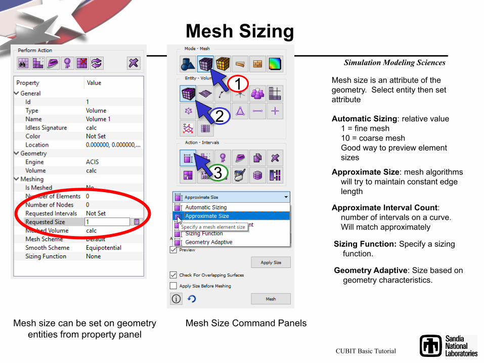
Mesh size can be set on geometry entities from property panel
Mesh Size Command Panels
Mesh size is an attribute of the geometry. Select entity then set attribute
Automatic Sizing: relative value1 = fine mesh10 = coarse meshGood way to preview element sizes
Approximate Size: mesh algorithms will try to maintain constant edge length
Approximate Interval Count: number of intervals on a curve. Will match approximately
Geometry Adaptive: Size based on geometry characteristics.
1
2
3
CUBIT Basic Tutorial
Sizing Function: Specify a sizing function.
Simulation Modeling Sciences
Auto Mesh Sizing
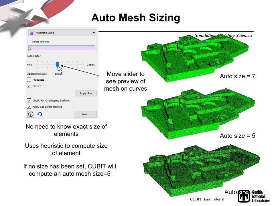
Move slider to see preview of
mesh on curves
No need to know exact size of elements
Uses heuristic to compute size of element
If no size has been set, CUBIT will compute an auto mesh size=5
Auto size = 7
Auto size = 5
Auto size = 1CUBIT Basic Tutorial
Simulation Modeling Sciences
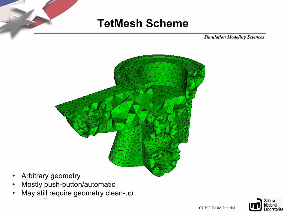
TetMesh Scheme
• Arbitrary geometry• Mostly push-button/automatic• May still require geometry clean-up
CUBIT Basic Tutorial

Simulation Modeling Sciences
1
2
3
TetMesh Scheme
CUBIT Basic Tutorial
Simulation Modeling Sciences
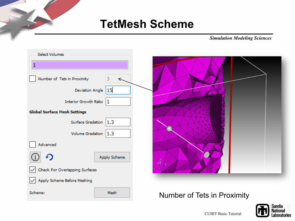
TetMesh Scheme
Number of Tets in Proximity
CUBIT Basic Tutorial
Simulation Modeling Sciences
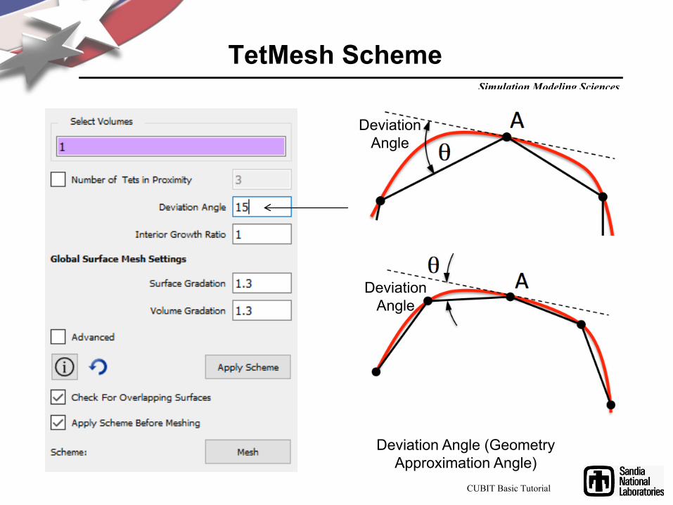
TetMesh Scheme
Deviation Angle (Geometry Approximation Angle)
Deviation Angle
Deviation Angle
CUBIT Basic Tutorial

Simulation Modeling Sciences
TetMesh Scheme
Deviation Angle (Geometry Approximation Angle)
CUBIT Basic Tutorial

Simulation Modeling Sciences
TetMesh Scheme
Interior Growth Ratio
1.01.3
CUBIT Basic Tutorial
Simulation Modeling Sciences
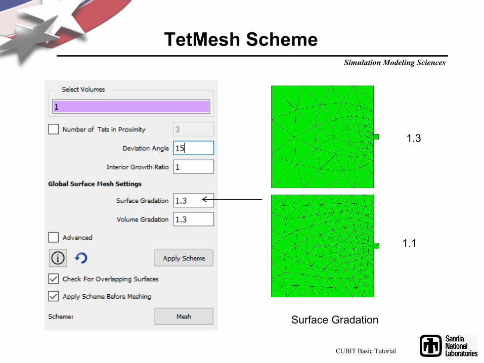
TetMesh Scheme
Surface Gradation
1.3
1.1
CUBIT Basic Tutorial

Simulation Modeling Sciences
TetMesh Scheme
Surface Volume Gradation
CUBIT Basic Tutorial

Simulation Modeling Sciences
TetMesh Scheme
Tet Respect: Force TetMesh to conform to internal features
(specified here)
Tetmesh Global SettingsMesh Optimization settings not
normally changed
CUBIT Basic Tutorial
Simulation Modeling Sciences
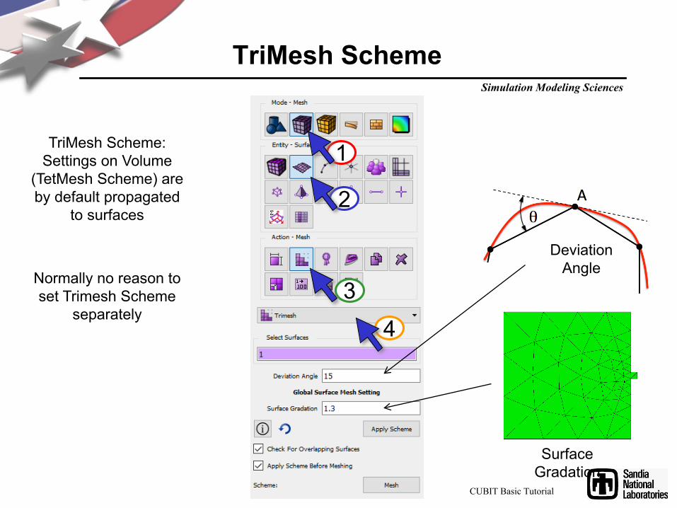
TriMesh Scheme
TriMesh Scheme:Settings on Volume
(TetMesh Scheme) are by default propagated
to surfaces
Normally no reason to set Trimesh Scheme
separately
Deviation Angle
Surface Gradation
1
2
34
CUBIT Basic Tutorial
Simulation Modeling Sciences
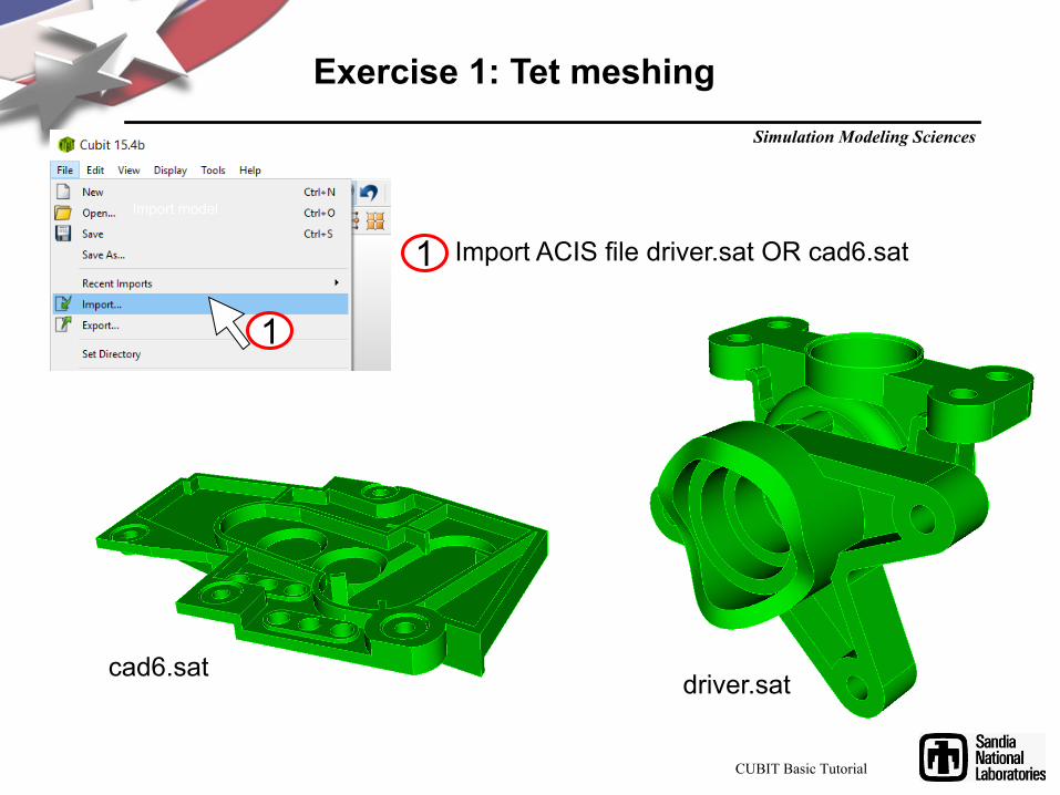
Import model
Import ACIS file driver.sat OR cad6.sat
driver.satcad6.sat
1
1
Exercise 1: Tet meshing
CUBIT Basic Tutorial
Simulation Modeling Sciences
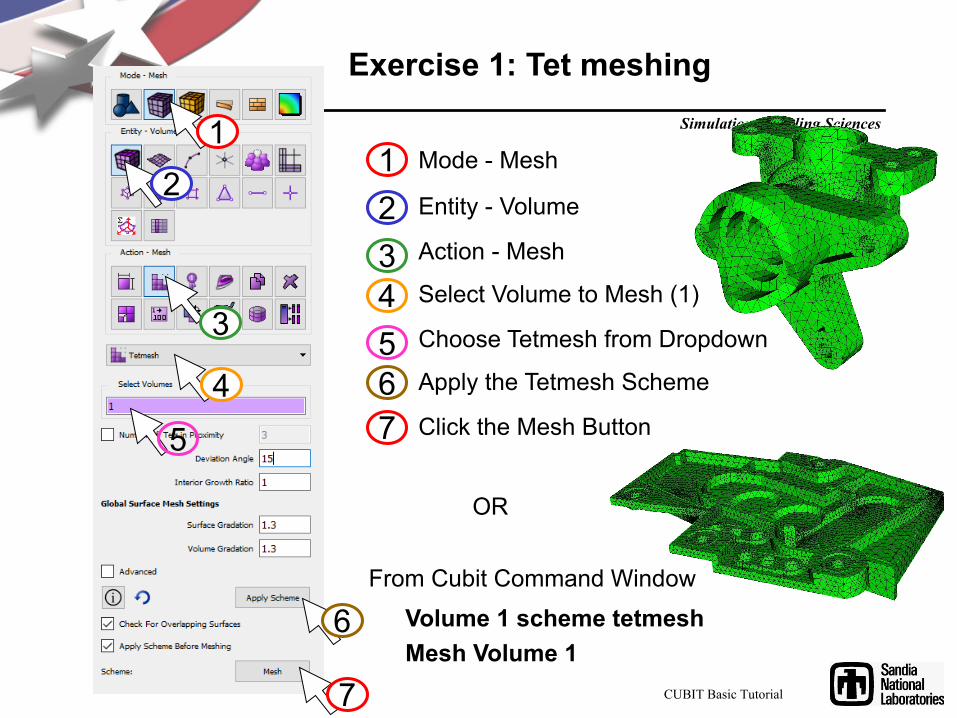
Exercise 1: Tet meshing
Mode - Mesh
Entity - Volume
Action - Mesh
Select Volume to Mesh (1)
Choose Tetmesh from Dropdown
Apply the Tetmesh Scheme
Click the Mesh Button
OR
Volume 1 scheme tetmeshMesh Volume 1
From Cubit Command Window
1234567
12
3
45
6
7 CUBIT Basic Tutorial
Simulation Modeling Sciences
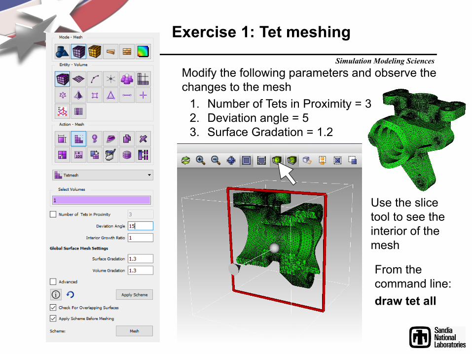
Modify the following parameters and observe the changes to the mesh
1. Number of Tets in Proximity = 32. Deviation angle = 53. Surface Gradation = 1.2
Use the slice tool to see the interior of the mesh
From the command line:draw tet all
Exercise 1: Tet meshing
Simulation Modeling Sciences
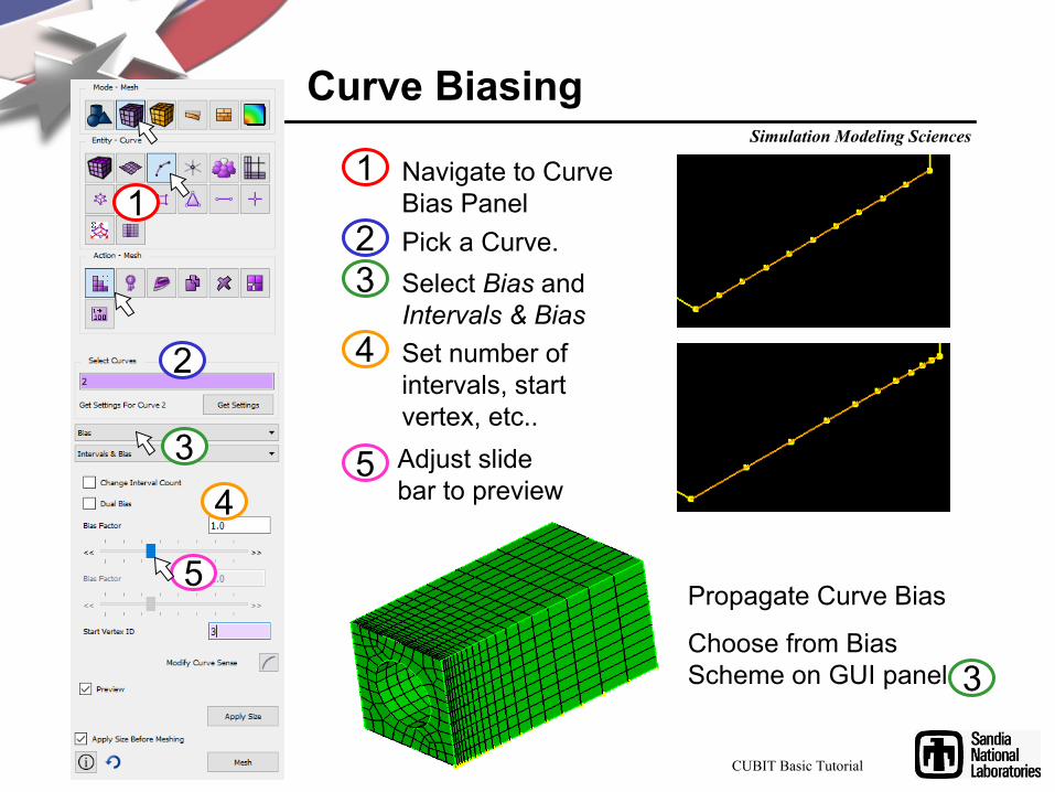
Curve Biasing
Select Bias and Intervals & Bias
Pick a Curve.
Adjust slide bar to preview biased mesh.
Navigate to Curve Bias Panel
1
23
4 Set number of intervals, start vertex, etc..
5
1
2
34
5Propagate Curve Bias
Choose from Bias Scheme on GUI panel 3
CUBIT Basic Tutorial
Simulation Modeling Sciences
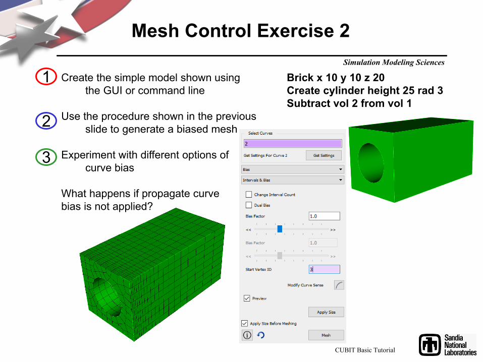
Mesh Control Exercise 2
Create the simple model shown using the GUI or command line
Use the procedure shown in the previous slide to generate a biased mesh
Experiment with different options of curve bias
What happens if propagate curve bias is not applied?
1
2
Brick x 10 y 10 z 20Create cylinder height 25 rad 3Subtract vol 2 from vol 1
3
CUBIT Basic Tutorial
Simulation Modeling Sciences
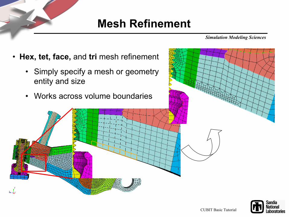
Mesh Refinement
• Hex, tet, face, and tri mesh refinement
• Simply specify a mesh or geometry entity and size
• Works across volume boundaries
CUBIT Basic Tutorial
Simulation Modeling Sciences
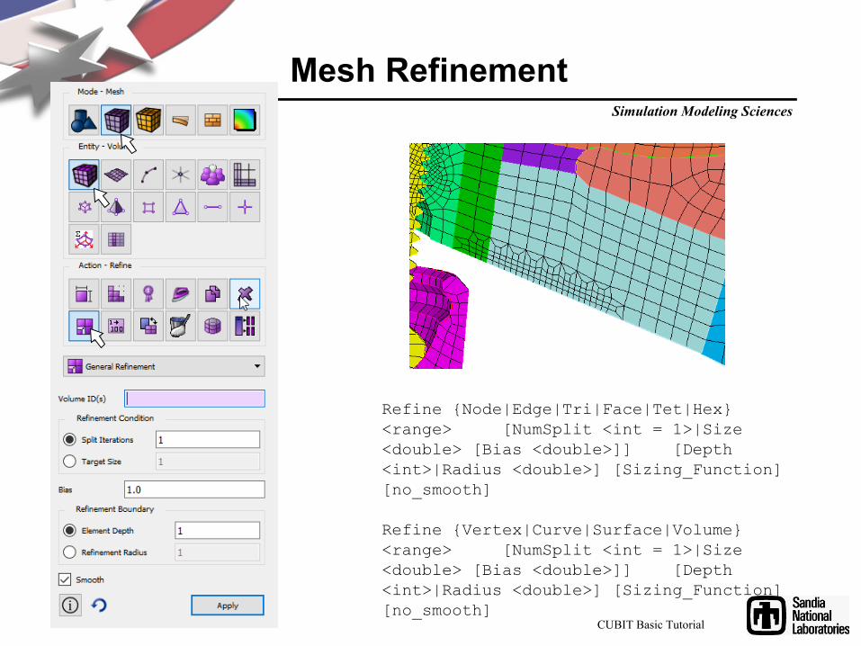
Mesh Refinement
Refine {Node|Edge|Tri|Face|Tet|Hex} <range> [NumSplit <int = 1>|Size <double> [Bias <double>]] [Depth <int>|Radius <double>] [Sizing_Function] [no_smooth]
Refine {Vertex|Curve|Surface|Volume} <range> [NumSplit <int = 1>|Size <double> [Bias <double>]] [Depth <int>|Radius <double>] [Sizing_Function] [no_smooth]
CUBIT Basic Tutorial

Simulation Modeling Sciences
Mesh Control Exercise 3
1
2
3
Use the same model you created for exercise 2 and reset the volume
Use the refine surface command panel to generate a graded hex mesh. Try an element depth of 5.
Reset the volume, generate a tet mesh and use the same tool to generate a graded tet mesh
Graded hex mesh using element depth 5 applied twice
Graded tet mesh using element depth 5 applied twice

Simulation Modeling Sciences
Mesh Quality Command Panel
Select a Quality Metric
Select a meshed volume to examine
Navigate to Mesh Quality Panel
1
2
34 Select the options for displaying the metrics
23
4
1
Note that this panel is available for volumes, surfaces and elements
CUBIT Basic Tutorial

Simulation Modeling Sciences
Quality Metrics
• Definitions of the metrics are in the online documentation– Go to the quality page and hit the F1 key
Function Name Dimension Full Range Acceptable Range Reference Aspect Ratio 1 to inf 1 to 4 [5]Skew 0 to 1 0 to 0.5 [5]Taper 0 to +inf 0 to 0.4 [5]Element Volume -inf to +inf None [5]Stretch 0 to 1 0.25 to 1 [6]Diagonal Ratio 0 to 1 0.65 to 1Dimension 0 to +inf None [5]
0 to +inf 0 to 20 [7][8]Condition No. 1 to inf 1 to 8 [8]Jacobian -inf to +inf None [8]Scaled Jacobian -1 to +1 0.5 to 1 [8]Shear 0 to 1 0.3 to 1 [9]Shape 0 to 1 0.3 to 1 [9]Relative Size 0 to 1 0.5 to 1 [9]
L0
L0
L0
L3
L0
L0
L1
Oddy L0
L0
L3
L0
L0
L0
L0
CUBIT Basic Tutorial
Simulation Modeling Sciences
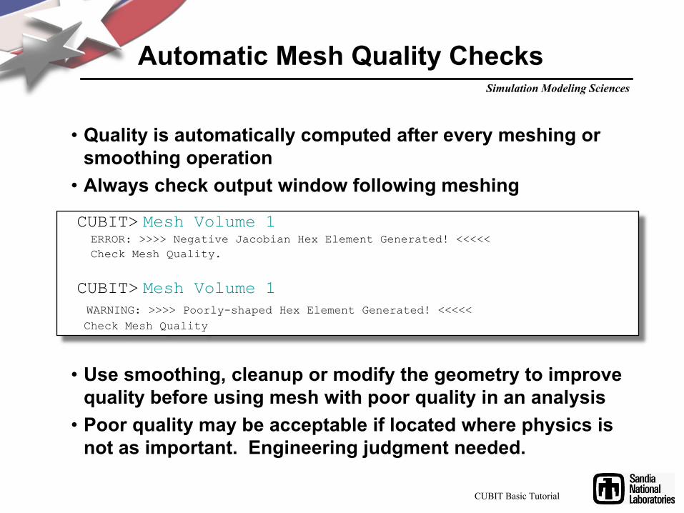
Automatic Mesh Quality Checks
• Quality is automatically computed after every meshing or smoothing operation
• Always check output window following meshing
CUBIT> Mesh Volume 1ERROR: >>>> Negative Jacobian Hex Element Generated! <<<<< Check Mesh Quality.
CUBIT> Mesh Volume 1WARNING: >>>> Poorly-shaped Hex Element Generated! <<<<< Check Mesh Quality
• Use smoothing, cleanup or modify the geometry to improve quality before using mesh with poor quality in an analysis
• Poor quality may be acceptable if located where physics is not as important. Engineering judgment needed.
CUBIT Basic Tutorial

Simulation Modeling Sciences
Mesh Quality
Select Options (or Preferences on Mac) menu to define quality metric(s) to use and the minimum and maximum criteria
Simulation Modeling Sciences
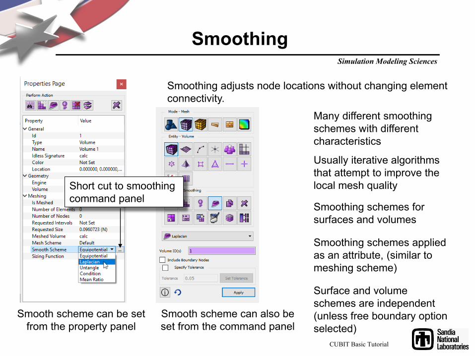
Smoothing
Smoothing adjusts node locations without changing element connectivity.
Usually iterative algorithms that attempt to improve the local mesh quality
Many different smoothing schemes with different characteristics
Smooth scheme can be set from the property panel
Smooth scheme can also be set from the command panel
Short cut to smoothing command panel
Smoothing schemes for surfaces and volumes
Smoothing schemes applied as an attribute, (similar to meshing scheme)
Surface and volume schemes are independent (unless free boundary option selected)
CUBIT Basic Tutorial

Simulation Modeling Sciences
Smoothing
• Laplacian– fast, poor quality near concave features
• Equipotential– medium fast and medium quality
• Untangle– remove stubborn inverted elements– Can take a long time– Control time limit:
Volume <range> Smooth Scheme Condition Number [beta <double=2.0>] [cpu <double=10>]
• Condition number– Guarantees the same or better quality– improve stubborn low-quality elements– must be non-inverted to start (runs untangle if
inverted)– Can take a long time– Control time limit:
Volume <range> Smooth Scheme Condition Number [beta <double=2.0>] [cpu <double=10>]
• Equipotential• Centroid Area Pull• Optimize Jacobian• Winslow
– longtime favorite for structured meshes has been extended to unstructured in CUBIT - theoretical guarantee against mesh folding
– fast and high quality, try first• Laplacian, centroid area pull (smart Laplacian)
– fast, poor near concave features• Untangle
– remove stubborn inverted elements• Condition number
– improve stubborn low-quality elements– must be non-inverted to start
• Mean Ratio
Surface Smoothing Schemes Volume Smoothing Schemes
Simulation Modeling Sciences
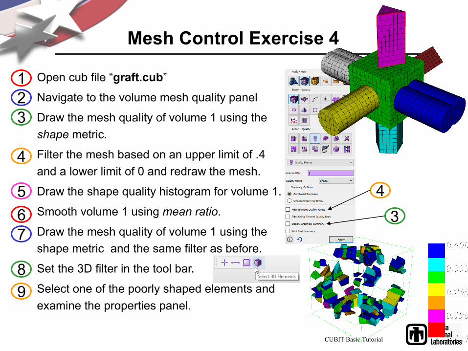
Mesh Control Exercise 4
Open cub file “graft.cub”
Navigate to the volume mesh quality panel
Draw the mesh quality of volume 1 using the shape metric.
Filter the mesh based on an upper limit of .4 and a lower limit of 0 and redraw the mesh.
Draw the shape quality histogram for volume 1.
Smooth volume 1 using mean ratio.
Draw the mesh quality of volume 1 using the shape metric and the same filter as before.
Set the 3D filter in the tool bar.
Select one of the poorly shaped elements and examine the properties panel.
123
4
567
89
34
CUBIT Basic Tutorial

Simulation Modeling Sciences
Mesh Control Exercise 5
Surface 5512345
6
7
89
Import the acis file “driver.sat”Draw surface 55Set the mesh size to 1.0 on surface 55Mesh surface 55 using the paving scheme
Check the edge length quality. Use the quality command panel located under edge elements
What is the smallest edge length? Average edge length? Zoom to the smallest edge.
Use the edge length surface smoothing scheme to smooth surface 55
Check the edge length quality again for surface 55
Note any changes to the mesh What is the smallest edge length now?
The paver can sometimes create small edges in order to resolve the mesh
CUBIT Basic Tutorial
Simulation Modeling Sciences
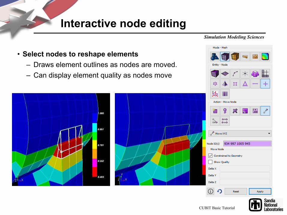
Interactive node editing
• Select nodes to reshape elements– Draws element outlines as nodes are moved.– Can display element quality as nodes move
CUBIT Basic Tutorial
Simulation Modeling Sciences
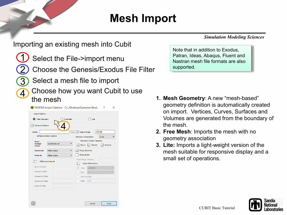
Mesh Import
Importing an existing mesh into Cubit
Select the File->import menuChoose the Genesis/Exodus File FilterSelect a mesh file to import
Note that in addition to Exodus, Patran, Ideas, Abaqus, Fluent and Nastran mesh file formats are also supported.
123
Choose how you want Cubit to use the mesh
4
4
1. Mesh Geometry: A new “mesh-based” geometry definition is automatically created on import. Vertices, Curves, Surfaces and Volumes are generated from the boundary of the mesh.
2. Free Mesh: Imports the mesh with no geometry association
3. Lite: Imports a light-weight version of the mesh suitable for responsive display and a small set of operations.
CUBIT Basic Tutorial
Simulation Modeling Sciences
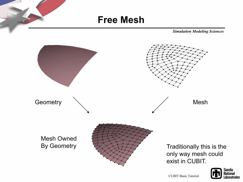
Free Mesh
Geometry Mesh
Mesh Owned By Geometry Traditionally this is the
only way mesh could exist in CUBIT.
CUBIT Basic Tutorial
Simulation Modeling Sciences
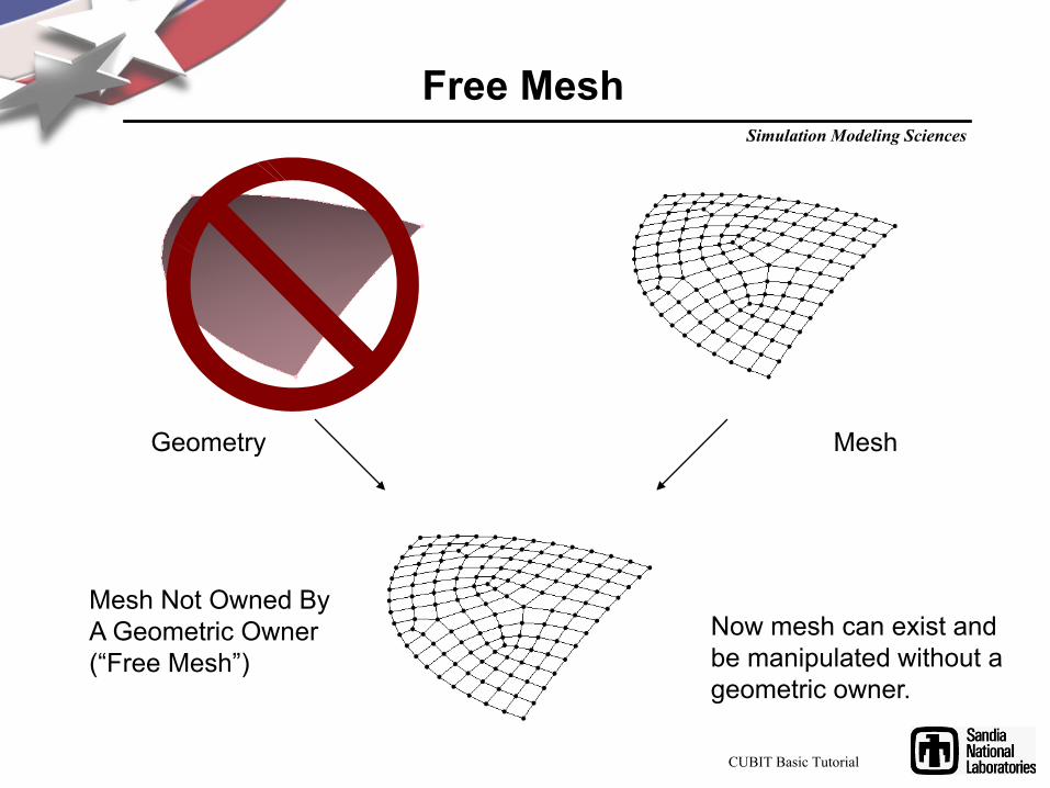
Free Mesh
Geometry Mesh
Mesh Not Owned By A Geometric Owner (“Free Mesh”)
Now mesh can exist and be manipulated without a geometric owner.
CUBIT Basic Tutorial

Simulation Modeling Sciences
Mesh Control Exercise 6
Import the exodus file “crunch.e” as a mesh-based geometry. Use a feature angle of 0Examine the mesh quality. What do you notice?
Navigate to the Remesh Tet Command Panel
1
2
3
crunch.e
Tet mesh after deformations applied from an analysis
3
3
3CUBIT Basic Tutorial

Simulation Modeling Sciences
5678
9
4
Mesh Control Exercise 6 (con.)
Select Remesh Poor Quality
Select Scaled Jacobian
Use a value < 0.1
Select Preview Only
Click ApplyThe elements in the mesh that meet the criteria of scaled Jacobian less than 0.1 will be displayed. These are the elements that will be remeshed. (The rest of the mesh will not be affected)
Uncheck the Preview Only Toggle
Click Apply1011 Examine the mesh quality.
What do you notice?
CUBIT Basic Tutorial