coreform cubit item tutorial
TRANSCRIPT
1
Coreform Cubit ITEM Tutorial
Overview
In this tutorial, you will see how to use of the Immersive Topology Environment for
Meshing (ITEM) to create a finite element mesh. ITEM is a wizard-like environment that
will guide you through a typical mesh generation process from import to export. Each
page in the ITEM workflow is linked to other pages, and you will be able to easily move
around in the environment by clicking on links on each page. Most of the pages contain
diagnostic tools that search the model for specific geometry or mesh-related issues.
Clicking on an entity in the ITEM output window will then generate specific command
suggestions to resolve the problem. The following topics are included in this tutorial:
• Importing a geometry
• Creating the finite element model
• Removing small features
• Using merge tolerance to find and fix small misalignments
• Decomposing a model
• Generating a mesh
• Validating the mesh
• Creating boundary conditions
• Exporting the mesh
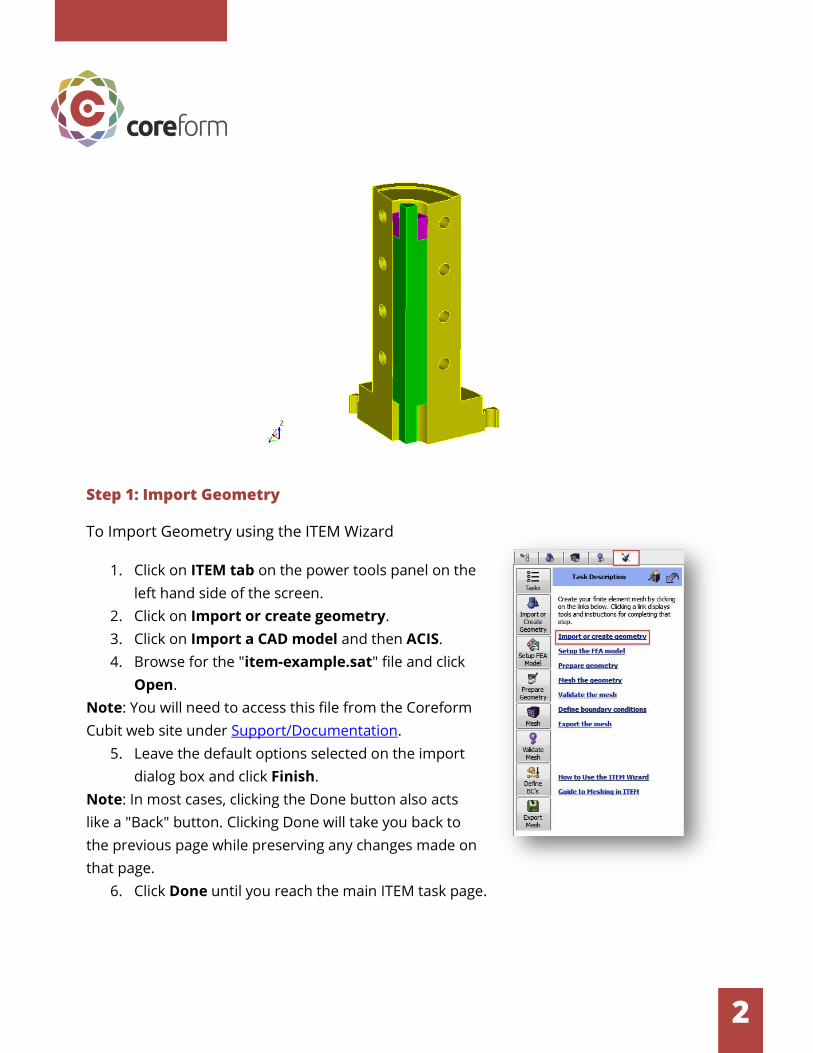
The model that will be used is shown below.
2
Step 1: Import Geometry
To Import Geometry using the ITEM Wizard
1. Click on ITEM tab on the power tools panel on the
left hand side of the screen.
2. Click on Import or create geometry.
3. Click on Import a CAD model and then ACIS.
4. Browse for the "item-example.sat" file and click
Open.
Note: You will need to access this file from the Coreform
Cubit web site under Support/Documentation.
5. Leave the default options selected on the import
dialog box and click Finish.
Note: In most cases, clicking the Done button also acts
like a "Back" button. Clicking Done will take you back to
the previous page while preserving any changes made on
that page.
6. Click Done until you reach the main ITEM task page.
3
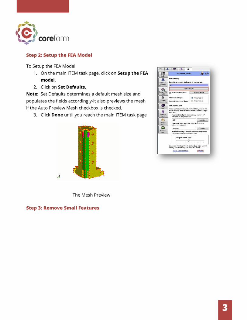
Step 2: Setup the FEA Model
To Setup the FEA Model
1. On the main ITEM task page, click on Setup the FEA
model.
2. Click on Set Defaults.
Note: Set Defaults determines a default mesh size and
populates the fields accordingly-it also previews the mesh
if the Auto Preview Mesh checkbox is checked.
3. Click Done until you reach the main ITEM task page
The Mesh Preview
Step 3: Remove Small Features
4
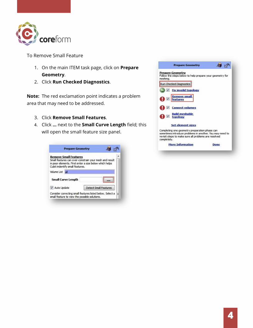
To Remove Small Feature
1. On the main ITEM task page, click on Prepare
Geometry.
2. Click Run Checked Diagnostics.
Note: The red exclamation point indicates a problem
area that may need to be addressed.
3. Click Remove Small Features.
4. Click ... next to the Small Curve Length field; this
will open the small feature size panel.
5
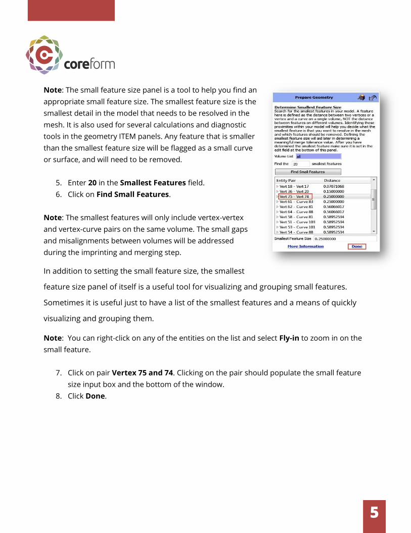
Note: The small feature size panel is a tool to help you find an
appropriate small feature size. The smallest feature size is the
smallest detail in the model that needs to be resolved in the
mesh. It is also used for several calculations and diagnostic
tools in the geometry ITEM panels. Any feature that is smaller
than the smallest feature size will be flagged as a small curve
or surface, and will need to be removed.
5. Enter 20 in the Smallest Features field.
6. Click on Find Small Features.
Note: The smallest features will only include vertex-vertex
and vertex-curve pairs on the same volume. The small gaps
and misalignments between volumes will be addressed
during the imprinting and merging step.
In addition to setting the small feature size, the smallest
feature size panel of itself is a useful tool for visualizing and grouping small features.
Sometimes it is useful just to have a list of the smallest features and a means of quickly
visualizing and grouping them.
Note: You can right-click on any of the entities on the list and select Fly-in to zoom in on the
small feature.
7. Click on pair Vertex 75 and 74. Clicking on the pair should populate the small feature
size input box and the bottom of the window.
8. Click Done.
6
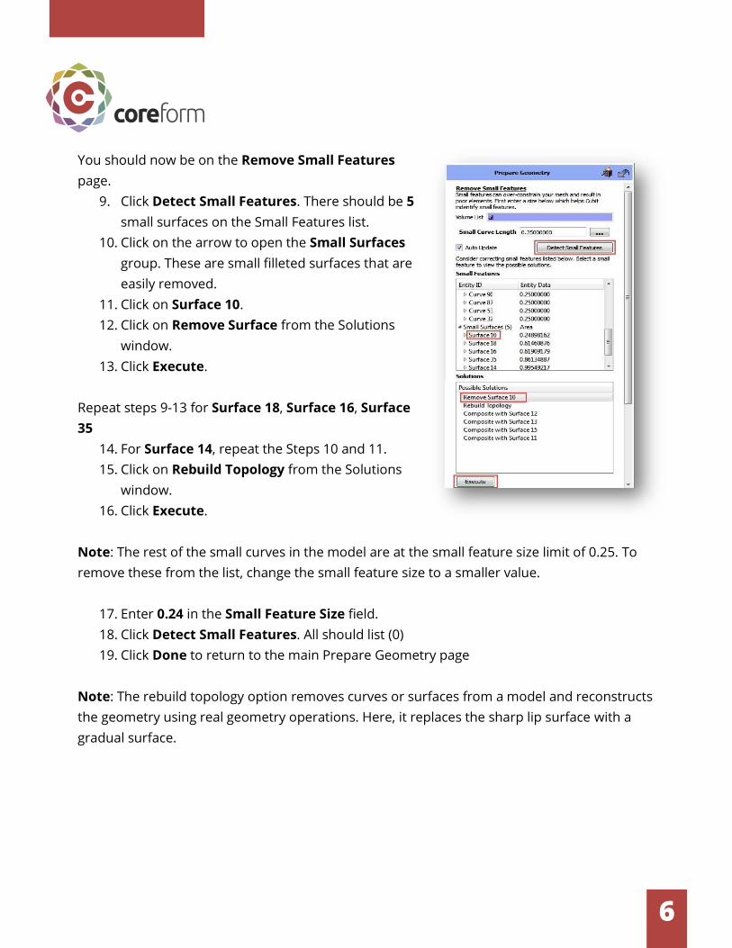
You should now be on the Remove Small Features
page.
9. Click Detect Small Features. There should be 5
small surfaces on the Small Features list.
10. Click on the arrow to open the Small Surfaces
group. These are small filleted surfaces that are
easily removed.
11. Click on Surface 10.
12. Click on Remove Surface from the Solutions
window.
13. Click Execute.
Repeat steps 9-13 for Surface 18, Surface 16, Surface
35
14. For Surface 14, repeat the Steps 10 and 11.
15. Click on Rebuild Topology from the Solutions
window.
16. Click Execute.
Note: The rest of the small curves in the model are at the small feature size limit of 0.25. To
remove these from the list, change the small feature size to a smaller value.
17. Enter 0.24 in the Small Feature Size field.
18. Click Detect Small Features. All should list (0)
19. Click Done to return to the main Prepare Geometry page
Note: The rebuild topology option removes curves or surfaces from a model and reconstructs
the geometry using real geometry operations. Here, it replaces the sharp lip surface with a
gradual surface.
7
Step 4: Connect Volumes
In this next step of the mesh generation process, you will merge all shared curves and
surfaces. This is necessary so that adjacent volumes can share boundary meshes. For
most geometries, this step presents no major complications. But in many cases,
misalignments, tolerance problems, or other cleanup operations can prevent proper
merging. The ITEM panel is designed to guide you through imprint/merge problems.
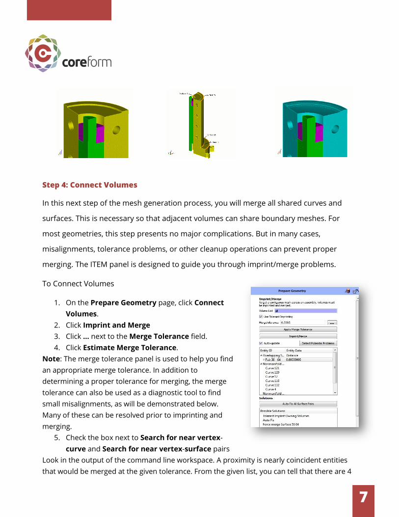
To Connect Volumes
1. On the Prepare Geometry page, click Connect
Volumes.
2. Click Imprint and Merge
3. Click ... next to the Merge Tolerance field.
4. Click Estimate Merge Tolerance.
Note: The merge tolerance panel is used to help you find
an appropriate merge tolerance. In addition to
determining a proper tolerance for merging, the merge
tolerance can also be used as a diagnostic tool to find
small misalignments, as will be demonstrated below.
Many of these can be resolved prior to imprinting and
merging.
5. Check the box next to Search for near vertex-
curve and Search for near vertex-surface pairs
Look in the output of the command line workspace. A proximity is nearly coincident entities
that would be merged at the given tolerance. From the given list, you can tell that there are 4
8
entities that would be merged at a merge tolerance of 0.025 which would not be merged if the
merge tolerance were 0. This means that those entities are less than 0.025 apart.
6. Change the search parameter to a very small number, Min=0.001.
7. Click Search. Four vertex-vertex pairs appear.
8. Expand Vertex/Vertex Pairs group and click the first pair (Pair 12-77).
9. Click on the first solution (tweak surface 46 to surface 7).
10. Click Execute.
11. Click Done to return to the Imprint/Merge page.
12. Click the Imprint/Merge button.
13. Click Detect Potential Problems.
If you have Overlapping Surfaces, click on Auto Fix All Surface Pairs.
No problems should appear on the list, signifying that imprinting and merging has most
likely been successful. There are several diagnostic tools on this page that help to
determine if imprint/merging has been successful. These include:
• Overlapping Surfaces- Surfaces that overlap, but are not merged.
• Non-manifold curves- Two curves that are merged but that don't have any merged
surfaces.
• Non-manifold vertices- Two vertices that are merged, but do not share any merged
curves.
• Floating volumes- Volumes that are not connected to any other volumes (meaning
they are not merged)
All of these diagnostics could be run at any time, but the results are most meaningful
after an imprint/merge operation.
14. Click Done until you reach the main Prepare Geometry page.
Step 5: Build a Meshable Topology
The next step in the mesh generation process may be a bit more challenging. Building a
meshable topology involves decomposing an assembly into meshable parts. For
sweeping, this means decomposing it into volumes composed of many-to-one and one-
9
to-one sweepable parts. Each decomposed volume is further constrained because it
needs to be able to share boundary meshes on merged surfaces. Since the numbers of
possible decomposition strategies are numerous, it is not yet possible to automatically
decompose most models. Instead, the ITEM framework seeks to provide possible
decomposition options for you, which they can be easily executed (and if necessary,
quickly undone).
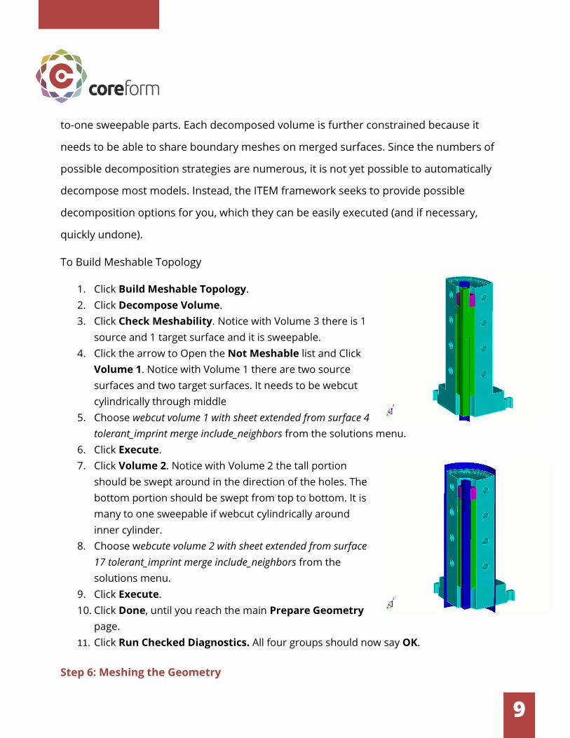
To Build Meshable Topology
1. Click Build Meshable Topology.
2. Click Decompose Volume.
3. Click Check Meshability. Notice with Volume 3 there is 1
source and 1 target surface and it is sweepable.
4. Click the arrow to Open the Not Meshable list and Click
Volume 1. Notice with Volume 1 there are two source
surfaces and two target surfaces. It needs to be webcut
cylindrically through middle
5. Choose webcut volume 1 with sheet extended from surface 4
tolerant_imprint merge include_neighbors from the solutions menu.
6. Click Execute.
7. Click Volume 2. Notice with Volume 2 the tall portion
should be swept around in the direction of the holes. The
bottom portion should be swept from top to bottom. It is
many to one sweepable if webcut cylindrically around
inner cylinder.
8. Choose webcute volume 2 with sheet extended from surface
17 tolerant_imprint merge include_neighbors from the
solutions menu.
9. Click Execute.
10. Click Done, until you reach the main Prepare Geometry
page.
11. Click Run Checked Diagnostics. All four groups should now say OK.
Step 6: Meshing the Geometry
10
The actual mesh generation process is usually quite iterative. Rare is the case where
meshing succeeds perfectly on the first try, even when all volumes are "meshable". Even if
it does succeed, it is usually constrained by areas of poor quality elements. ITEM was
designed to help you navigate the iterative mesh generation process. When meshing fails,
the mesh generation panel helps to explain common error messages and suggest
possible strategies for getting a model to mesh.
Change the mesh size and then mesh the geometry
1. Click on Setup the FEA model.
2. Notice the Target Mesh Size box at the bottom of the panel. Change the mesh size
by moving the target mesh size slider one position to the left.
3. Click Apply next to the Element Size field.
4. Click Done.
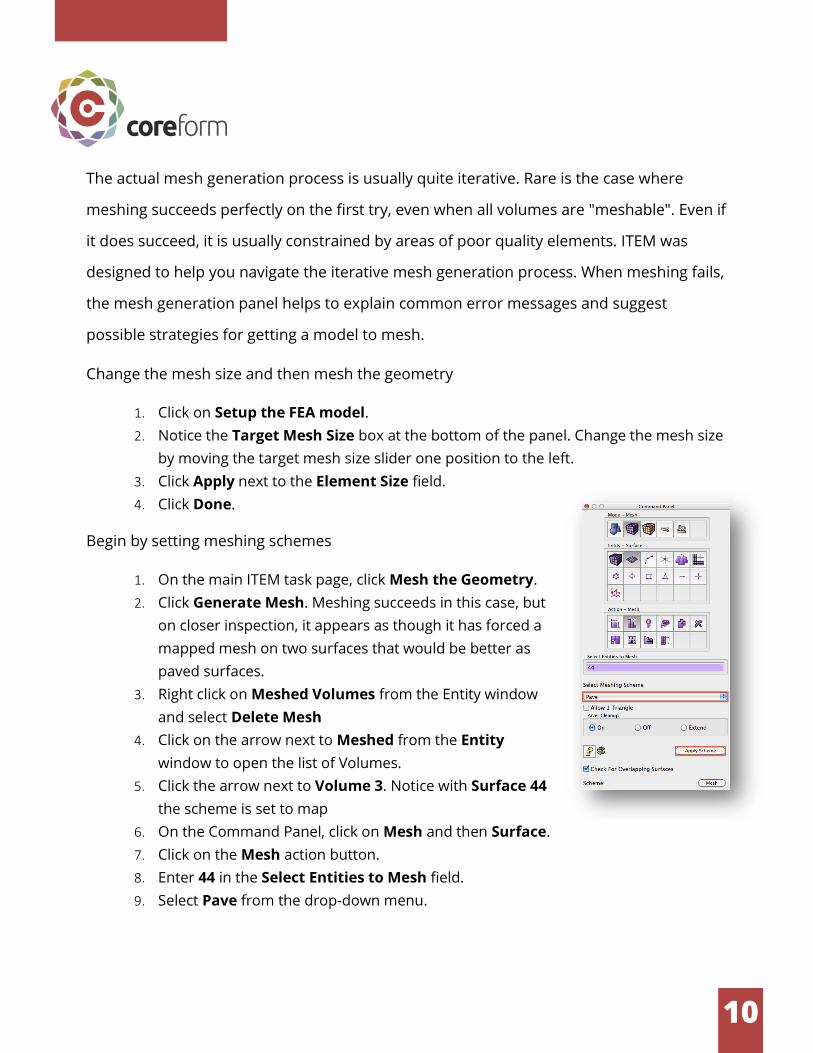
Begin by setting meshing schemes
1. On the main ITEM task page, click Mesh the Geometry.
2. Click Generate Mesh. Meshing succeeds in this case, but
on closer inspection, it appears as though it has forced a
mapped mesh on two surfaces that would be better as
paved surfaces.
3. Right click on Meshed Volumes from the Entity window
and select Delete Mesh
4. Click on the arrow next to Meshed from the Entity
window to open the list of Volumes.
5. Click the arrow next to Volume 3. Notice with Surface 44
the scheme is set to map
6. On the Command Panel, click on Mesh and then Surface.
7. Click on the Mesh action button.
8. Enter 44 in the Select Entities to Mesh field.
9. Select Pave from the drop-down menu.
11
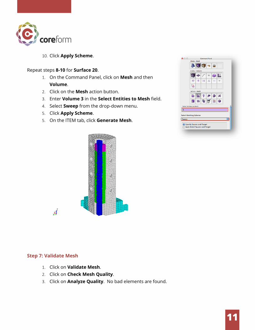
10. Click Apply Scheme.
Repeat steps 8-10 for Surface 20.
1. On the Command Panel, click on Mesh and then
Volume.
2. Click on the Mesh action button.
3. Enter Volume 3 in the Select Entities to Mesh field.
4. Select Sweep from the drop-down menu.
5. Click Apply Scheme.
5. On the ITEM tab, click Generate Mesh.
Step 7: Validate Mesh
1. Click on Validate Mesh.
2. Click on Check Mesh Quality.
3. Click on Analyze Quality. No bad elements are found.
12
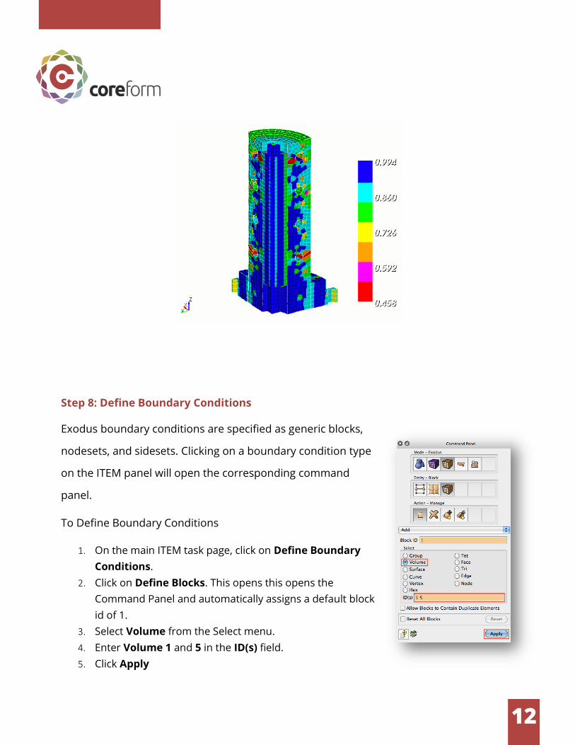
Step 8: Define Boundary Conditions
Exodus boundary conditions are specified as generic blocks,
nodesets, and sidesets. Clicking on a boundary condition type
on the ITEM panel will open the corresponding command
panel.
To Define Boundary Conditions
1. On the main ITEM task page, click on Define Boundary
Conditions.
2. Click on Define Blocks. This opens this opens the
Command Panel and automatically assigns a default block
id of 1.
3. Select Volume from the Select menu.
4. Enter Volume 1 and 5 in the ID(s) field.
5. Click Apply
13
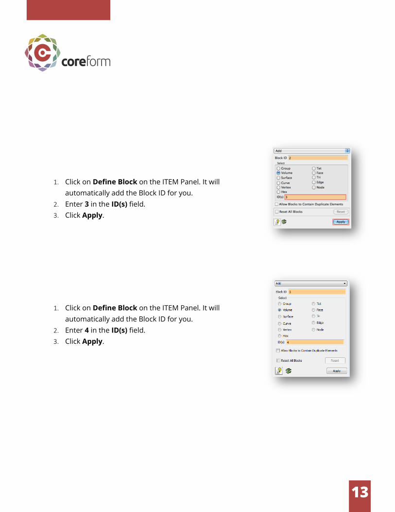
1. Click on Define Block on the ITEM Panel. It will
automatically add the Block ID for you. 2. Enter 3 in the ID(s) field.
3. Click Apply.
1. Click on Define Block on the ITEM Panel. It will
automatically add the Block ID for you. 2. Enter 4 in the ID(s) field.
3. Click Apply.
14
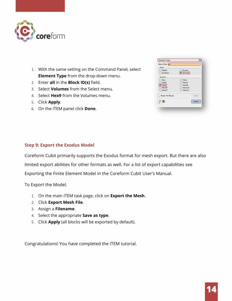
1. With the same setting on the Command Panel, select
Element Type from the drop-down menu.
2. Enter all in the Block ID(s) field.
3. Select Volumes from the Select menu.
4. Select Hex9 from the Volumes menu.
5. Click Apply.
6. On the ITEM panel click Done.
Step 9: Export the Exodus Model
Coreform Cubit primarily supports the Exodus format for mesh export. But there are also
limited export abilities for other formats as well. For a list of export capabilities see
Exporting the Finite Element Model in the Coreform Cubit User’s Manual.
To Export the Model.
1. On the main ITEM task page, click on Export the Mesh.
2. Click Export Mesh File.
3. Assign a Filename.
4. Select the appropriate Save as type.
5. Click Apply (all blocks will be exported by default).
Congratulations! You have completed the ITEM tutorial.