111085r-rfusp37v02 report-太瀚 rck-t07, rck-t07s -vers…1 pc hp dtpc27 sg21200950 doc...
TRANSCRIPT

Report No:111085R-RFUSP37V02
Page: 1 of 50
Test Report
Product Name : Tablet: Wireless Tablet X860/X861;
Dongle: Wireless Tablet Receiver X860/X861
Model No. : Tablet: RCK-T07, RCK-T07S;
Dongle: RCK-T07R, RCK-T07RS
FCC ID. : DoC
Applicant : WALTOP International Corp.
Address : 3F, No.6-8 Du-Sing RD., Hsin-Chu Science Park,
Hsin-Chu City 30078, Taiwan, R.O.C.
Date of Receipt : 2010/12/30
Issued Date : 2011/02/09
Report No. : 111085R-RFUSP37V02
Report Version : V1.0
The test results relate only to the samples tested. The test report shall not be reproduced except in full without the written approval of QuieTek Corporation.

DECLARATION OF CONFORMITY Per FCC Part 2 Section 2. 1077(a)
The following equipment:
Product Name : Tablet: Wireless Tablet X860/X861;
Dongle: Wireless Tablet Receiver X860/X861
Trade Name : LUIDIA, WALTOP
Model Number : Tablet: RCK-T07, RCK-T07S;
Dongle: RCK-T07R, RCK-T07RS
Company Name : WALTOP International Corp.
It’s herewith confirmed to comply with the requirements of FCC Part 15 Rules. (Class B)
Operation is subject to the following two conditions:
(1) This device may not cause harmful interference, and
(2) This device must accept any interference received, including interference that
may cause undesired operation.
The result of electromagnetic emission has been evaluated by QuieTek EMC
laboratory (NVLAP Lab. Code : 200347-0 ) and showed in the test report.
( Report No. : QTK-111085R-RFUSP37V02)
It is understood that each unit marketed is identical to the device as tested, and
Any changes to the device that could adversely affect the emission
Characteristics will require retest.
The following importer / manufacturer is responsible for this declaration:
Company Name
Company Address
Telephone Facsimile :
Person is responsible for marking this declaration:
Name ( Full name ) Position / Title
Date Legal Signature

Report No:111085R-RFUSP37V02
Page: 2 of 50
Test Report Cert i f icat ion Issued Date : 2011/02/09 Report No. : 111085R-RFUSP37V02
Product Name : Tablet: Wireless Tablet X860/X861;
Dongle: Wireless Tablet Receiver X860/X861
Applicant : WALTOP International Corp.
Address : 3F, No.6-8 Du-Sing RD., Hsin-Chu Science Park, Hsin-Chu
City 30078, Taiwan, R.O.C.
Manufacturer : WALTOP International Corp.
Model No. : Tablet: RCK-T07, RCK-T07S;
Dongle: RCK-T07R, RCK-T07RS
FCC ID. : DoC
EUT Voltage : AC 120 V / 60 Hz
Trade Name : LUIDIA, WALTOP
Applicable Standard : FCC CFR Title 47 Part 15 Subpart B: 2009
Test Result : Complied
The test results relate only to the samples tested. The test report shall not be reproduced except in full without the written approval of QuieTek Corporation.
Documented By :
(Sandy Chuang / Engineering Adm. Specialist )
Tested By :
( JuBo Shen / Engineer)
Approved By :
( Roy Wang / Manager)
Report No:111085R-RFUSP37V02
Page: 3 of 50
TABLE OF CONTENTS Description Page 1. General Information ..................................................................................................... 4 1.1. EUT Description ............................................................................................................. 4 1.2. Test Mode....................................................................................................................... 6 1.3. Tested System Details .................................................................................................... 7 1.4. Configuration of tested System ...................................................................................... 8 1.5. EUT Exercise Software ................................................................................................ 10 1.6. Test Facility................................................................................................................... 11 2. Conducted Emission.................................................................................................. 12 2.1. Test Equipment............................................................................................................. 12 2.2. Test Setup .................................................................................................................... 12 2.3. Limits ............................................................................................................................ 13 2.4. Test Procedure ............................................................................................................. 13 2.5. Test Specification.......................................................................................................... 13 2.6. Uncertainty ................................................................................................................... 13 2.7. Test Result....................................................................................................................14 2.8. Test Photo .................................................................................................................... 22 3. Radiated Emission ..................................................................................................... 24 3.1. Test Equipment............................................................................................................. 24 3.2. Test Setup .................................................................................................................... 24 3.3. Limits ............................................................................................................................ 25 3.4. Test Procedure ............................................................................................................. 26 3.5. Test Specification.......................................................................................................... 27 3.6. Uncertainty ................................................................................................................... 27 3.7. Test Result....................................................................................................................28 3.8. Test Photo .................................................................................................................... 44 Attachement......................................................................................................................................... 48 EUT Photograph........................................................................................................... 48
Reference : Laboratory of License

Report No:111085R-RFUSP37V02
Page: 4 of 50
1. General Information
1.1. EUT Description
Product Name Tablet: Wireless Tablet X860/X861; Dongle: Wireless Tablet Receiver X860/X861
Trade Name WALTOP, LUIDIA
Model No. Tablet: RCK-T07, RCK-T07S; Dongle: RCK-T07R, RCK-T07RS
Frequency Range 2402~2479MHz
Channel Number 78
Type of Modulation Direct Sequence Spread Spectrum (DSSS)
Antenna Gain -0.51dBi (Tablet)
-3.67dBi (Dongle)
Channel Control Auto
Antenna Type Soldered on PCB
Component
USB Cable Shielded, 1.5m, two ferrite cores bonded.
Working Frequency of Each Channel
Channel Frequency Channel Frequency Channel Frequency Channel Frequency
Channel 01 2402 MHz Channel 21 2422 MHz Channel 41 2442 MHz Channel 61 2462 MHz
Channel 02 2403 MHz Channel 22 2423 MHz Channel 42 2443 MHz Channel 62 2463 MHz
Channel 03 2404 MHz Channel 23 2424 MHz Channel 43 2444 MHz Channel 63 2464 MHz
Channel 04 2405 MHz Channel 24 2425 MHz Channel 44 2445 MHz Channel 64 2465 MHz
Channel 05 2406 MHz Channel 25 2426 MHz Channel 45 2446 MHz Channel 65 2466 MHz
Channel 06 2407 MHz Channel 26 2427 MHz Channel 46 2447 MHz Channel 66 2467 MHz
Channel 07 2408 MHz Channel 27 2428 MHz Channel 47 2448 MHz Channel 67 2468 MHz
Channel 08 2409 MHz Channel 28 2429 MHz Channel 48 2449 MHz Channel 68 2469 MHz
Channel 09 2410 MHz Channel 29 2430 MHz Channel 49 2450 MHz Channel 69 2470 MHz
Channel 10 2411 MHz Channel 30 2431 MHz Channel 50 2451 MHz Channel 70 2471 MHz
Channel 11 2412 MHz Channel 31 2432 MHz Channel 51 2452 MHz Channel 71 2472 MHz
Channel 12 2413 MHz Channel 32 2433 MHz Channel 52 2453 MHz Channel 72 2473 MHz
Channel 13 2414 MHz Channel 33 2434 MHz Channel 53 2454 MHz Channel 73 2474 MHz
Channel 14 2415 MHz Channel 34 2435 MHz Channel 54 2455 MHz Channel 74 2475 MHz
Channel 15 2416 MHz Channel 35 2436 MHz Channel 55 2456 MHz Channel 75 2476 MHz
Channel 16 2417 MHz Channel 36 2437 MHz Channel 56 2457 MHz Channel 76 2477 MHz
Channel 17 2418 MHz Channel 37 2438 MHz Channel 57 2458 MHz Channel 77 2478 MHz
Channel 18 2419 MHz Channel 38 2439 MHz Channel 58 2459 MHz Channel 78 2479 MHz
Channel 19 2420 MHz Channel 39 2440 MHz Channel 59 2460 MHz
Channel 20 2421 MHz Channel 40 2441 MHz Channel 60 2461 MHz

Report No:111085R-RFUSP37V02
Page: 5 of 50
Note:
1. This device is a Tablet: Wireless Tablet X860/X861; Dongle: Wireless Tablet Receiver
X860/X861 included a 2.4GHz receiving function, and 2.4GHz transmitting function.
2. These tests were conducted on a sample of the equipment for the purpose of demonstrating
compliance with Part 15 Subpart B for 2.4GHz Receiver
3. Regards to the frequent band operation; three channels were selected to perform the test,
then shown on this report.
4. This device is a composite device in accordance with Part 15 regulations. The function for the
2.4GHz transmitting was measured and made a test report that the report number is
111085R-RFUSP42V01, certified under FCC ID: Tablet: UBBRCKT07, Dongle:
UBBRCKT07R

Report No:111085R-RFUSP37V02
Page: 6 of 50
1.2. Test Mode
QuieTek has verified the construction and function in typical operation. All the test modes were
carried out with the EUT in normal operation, which was shown in this test report and defined
as:
Pre-Test Mode
EMI Mode 1: Receive (Tablet)
Mode 2: Receive (Dongle)
Final Test Mode
RX Mode 1: Receive (Tablet)
Mode 2: Receive (Dongle)

Report No:111085R-RFUSP37V02
Page: 7 of 50
1.3. Tested System Details
The types for all equipments, plus descriptions of all cables used in the tested system
(including inserted cards) are:
Test Mode Mode 1: Receive (Tablet)
Product Manufacturer Model No. Serial No. FCC ID Power Cord
1 PC HP DTPC27 SG21200950 DoC Non-shielded, 1.8m
2 Monitor CHI MEI A170E1-09 3UC120955SA1249 DoC Non-shielded, 1.8m
3 Modem ACEEX DM-1414 0102027543 DoC Non-shielded, 1.6m
4 Walkman AIWA US-J202 I20201 DoC --
5 Modem ACEEX DM-2814 960018054 DoC Non-shielded, 1.6m
6 Speaker Polk Audio 205 N/A DoC --
7 Mouse Logitech M-SBF83 HCA52200288 DoC --
8 Keyboard ACER 6311-TW2C N/A DoC --
9 Printer HP C2642A MY75L1D2XN DoC Non-shielded, 0.7m
10 PEN Electromagnetic
induction pen
M3A-020 N/A DoC --
Test Mode Mode 2: Receive (Dongle)
Product Manufacturer Model No. Serial No. FCC ID Power Cord
1 PC HP DTPC27 SG21200950 DoC Non-shielded, 1.8m
2 Monitor CHI MEI A170E1-09 3UC120955SA1249 DoC Non-shielded, 1.8m
3 Modem ACEEX DM-1414 0102027543 DoC Non-shielded, 1.6m
4 Walkman AIWA US-J202 I20201 DoC --
5 Modem ACEEX DM-2814 960018054 DoC Non-shielded, 1.6m
6 Speaker Polk Audio 205 N/A DoC --
7 Mouse Logitech M-SBF83 HCA52200184 DoC --
8 Mouse Logitech M-SBF83 HCA52200288 DoC --
9 Keyboard ACER 6311-TW2C N/A DoC --
10 Printer HP C2642A MY75L1D2XN DoC Non-shielded, 0.7m

Report No:111085R-RFUSP37V02
Page: 8 of 50
1.4. Configuration of tested System
Test Mode Mode 1: Receive (Tablet)
Connection Diagram
EUTPC(1)
Monitor(2)
Keyboard(8) Mouse(7)
Tablet(EUT)
Doagle(EUT)
PEN Printer(9)
Modem(3)Speaker(6) Walkman(4)Modem(5)
AB
C
DE
F
GHI
Signal Cable Type Signal cable Description
A Printer Cable Shielded, 1.2m
B VGA Cable Shielded, 1.8m, two ferrite cores bonded.
C USB Cable Shielded, 1.5m, two ferrite cores bonded.
D Modem Cable Shielded, 1.5m
E Walkman Cable Non-Shielded, 1.6m
F Modem Cable Shielded, 1.5m
G Speaker Cable Non-Shielded, 1.2m
H Mouse Cable Shielded, 1.8m
I Keyboard Cable Shielded, 1.5m

Report No:111085R-RFUSP37V02
Page: 9 of 50
Test Mode Mode 2: Receive (Dongle)
Connection Diagram
EUTPC(1)
Monitor(2)
Keyboard(9) Mouse(8)
Doagle(EUT)
Printer(10)
Modem(3)Speaker(6) Walkman(4)Modem(5)
AB
C
DE
F
G
HI
Mouse(7)
J
Signal Cable Type Signal cable Description
A Printer Cable Shielded, 1.2m
B VGA Cable Shielded, 1.8m, two ferrite cores bonded.
C USB Cable Shielded, 1.5m, two ferrite cores bonded.
D Modem Cable Shielded, 1.5m
E Walkman Cable Non-Shielded, 1.6m
F Modem Cable Shielded, 1.5m
G Speaker Cable Non-Shielded, 1.2m
H Mouse Cable Shielded, 1.8m
I Keyboard Cable Shielded, 1.5m
J Mouse Cable Shielded, 1.0m

Report No:111085R-RFUSP37V02
Page: 10 of 50
1.5. EUT Exercise Software
1 Setup the EUT and simulators as shown on 1.4
2 Turn on the power of all equipment.
3 Notebook PC reads data from disk.
4 Data will be receiving through EUT.
5 The receiving status will be shown on the monitor.
6 Repeat the above procedure (4) to (5)

Report No:111085R-RFUSP37V02
Page: 11 of 50
1.6. Test Facility
Ambient conditions in the laboratory:
Items Test Item Required (IEC 68-1) Actual
Temperature (C) 15 - 35 25
Humidity (%RH) 25 - 75 50
Barometric pressure (mbar)
FCC PART 15 B 15.107
Conducted Emission 860 - 1060 950-1000
Temperature (C) 15 - 35 25
Humidity (%RH) 25 - 75 65
Barometric pressure (mbar)
FCC PART 15 B 15.109
Radiated Emission 860 - 1060 950-1000
Site Description: September 27, 2010 File on
Federal Communications Commission
Laboratory Division
7435 Oakland Mills Road
Columbia, MD 21046
Registration Number: 365520
Accredited by TAF
Accreditation Number: 1313
Effective through: December 27, 2013
Accredited by NVLAP
NVLAP Lab Code: 200347-0
Effective through: September 30, 2011
Site Name: Quietek Corporation
Site Address: No.75-1, Wang-Yeh Valley, Yung-Hsing,
Chiung-Lin, Hsin-Chu County,
Taiwan, R.O.C.
TEL : 886-3-592-8858 / FAX : 886-3-592-8859
E-Mail : [email protected]

Report No:111085R-RFUSP37V02
Page: 12 of 50
2. Conducted Emission
2.1. Test Equipment
The following test equipment are used during the test:
Item Equipment Manufacturer Model No. / Serial No. Last Cal. Remark
1 Test Receiver R & S ESCS 30/825442/018 Sep., 2006
2 Artificial Mains Network R & S ENV4200/848411/10 Feb., 2007 Peripheral
3 LISN R & S ESH3-Z5/825562/002 Feb., 2007 EUT
4 Pulse Limiter R & S ESH3-Z2/357.8810.52 Feb., 2007
5 No.2 Shielded Room N/A
Note: All equipment upon which need to calibrated are with calibration period of 1 year.
2.2. Test Setup

Report No:111085R-RFUSP37V02
Page: 13 of 50
2.3. Limits
FCC Part 15 Subpart B Paragraph 15.107 Limits (dBuV)
Class A Class B Frequency
MHz QP AV QP AV
0.15 - 0.50 79 66 66-56 56-46
0.50 - 5.0 73 60 56 46
5.0 - 30 73 60 60 50
Remarks : In the above table, the tighter limit applies at the band edges.
2.4. Test Procedure
The EUT and simulators are connected to the main power through a line impedance
stabilization network (L.I.S.N.). This provides a 50 ohm /50uH coupling impedance for the
measuring equipment. The peripheral devices are also connected to the main power
through a LISN that provides a 50ohm/50uH coupling impedance with 50ohm termination.
(Please refers to the block diagram of the test setup and photographs.)
Both sides of A.C. line are checked for maximum conducted interference. In order to find
the maximum emission, the relative positions of equipment and all of the interface cables
must be changed according to ANSI C63.4: 2009 on conducted measurement.
Conducted emissions were invested over the frequency range from 0.15MHz to 30MHz
using a receiver bandwidth of 9kHz.
2.5. Test Specification
According to FCC CFR Title 47 Part 15 Subpart B: 2009
2.6. Uncertainty
The measurement uncertainty is defined as ± 2.26 dB.

Report No:111085R-RFUSP37V02
Page: 14 of 50
2.7. Test Result
Site : QuieTek Shielding Room2 Time : 2007/04/14 - 19:50
Limit : CISPR_B_00M_QP Margin : 0
EUT: Tablet: Wireless Tablet X860/X861; Dongle: Wireless
Tablet Receiver X860/X861
Probe : SR3_LISN(16A) - Line1
Power : AC 120V/60Hz Note : Mode 1: Receive (Tablet)
Frequency
(MHz)
Correct Factor
(dB)
Reading Level
(dBuV)
Measure Level
(dBuV)
Margin
(dB)
Limit
(dBuV)
Detector Type
1 * 0.162 0.141 46.500 46.641 -19.016 65.657 QUASIPEAK
2 0.221 0.160 40.790 40.950 -23.021 63.971 QUASIPEAK
3 0.302 0.178 31.260 31.438 -30.219 61.657 QUASIPEAK
4 1.427 0.300 21.830 22.130 -33.870 56.000 QUASIPEAK
5 3.782 0.430 25.610 26.040 -29.960 56.000 QUASIPEAK
6 10.971 0.750 24.970 25.720 -34.280 60.000 QUASIPEAK
Note:
1. All Reading Levels are Quasi-Peak and average value.
2. " * ", means this data is the worst emission level.
3.Measurement Level = Reading Level + Correct Factor

Report No:111085R-RFUSP37V02
Page: 15 of 50
Site : QuieTek Shielding Room2 Time : 2007/04/14 - 19:50
Limit : CISPR_B_00M_ AV Margin : 0
EUT: Tablet: Wireless Tablet X860/X861; Dongle: Wireless
Tablet Receiver X860/X861
Probe : SR3_LISN(16A) - Line1
Power : AC 120V/60Hz Note : Mode 1: Receive (Tablet)
Frequency
(MHz)
Correct Factor
(dB)
Reading Level
(dBuV)
Measure Level
(dBuV)
Margin
(dB)
Limit
(dBuV)
Detector Type
1 * 0.162 0.141 36.390 36.531 -19.126 55.657 AVERAGE
2 0.221 0.160 31.490 31.650 -22.321 53.971 AVERAGE
3 0.302 0.178 12.850 13.028 -38.629 51.657 AVERAGE
4 1.427 0.300 16.570 16.870 -29.130 46.000 AVERAGE
5 3.782 0.430 14.480 14.910 -31.090 46.000 AVERAGE
6 10.971 0.750 19.960 20.710 -29.290 50.000 AVERAGE
Note:
1. All Reading Levels are Quasi-Peak and average value.
2. " * ", means this data is the worst emission level.
3.Measurement Level = Reading Level + Correct Factor

Report No:111085R-RFUSP37V02
Page: 16 of 50
Site : QuieTek Shielding Room2 Time : 2007/04/14 - 19:54
Limit : CISPR_B_00M_QP Margin : 0
EUT: Tablet: Wireless Tablet X860/X861; Dongle: Wireless
Tablet Receiver X860/X861
Probe : SR3_LISN(16A) - Line2
Power : AC 120V/60Hz Note : Mode 1: Receive (Tablet)
Frequency
(MHz)
Correct Factor
(dB)
Reading Level
(dBuV)
Measure Level
(dBuV)
Margin
(dB)
Limit
(dBuV)
Detector Type
1 * 0.163 0.141 48.570 48.711 -16.918 65.629 QUASIPEAK
2 0.223 0.160 40.090 40.250 -23.664 63.914 QUASIPEAK
3 0.328 0.186 29.820 30.006 -30.908 60.914 QUASIPEAK
4 1.950 0.379 24.960 25.339 -30.661 56.000 QUASIPEAK
5 11.030 0.670 27.520 28.190 -31.810 60.000 QUASIPEAK
6 27.696 0.950 22.170 23.120 -36.880 60.000 QUASIPEAK
Note:
1. All Reading Levels are Quasi-Peak and average value.
2. " * ", means this data is the worst emission level.
3.Measurement Level = Reading Level + Correct Factor

Report No:111085R-RFUSP37V02
Page: 17 of 50
Site : QuieTek Shielding Room2 Time : 2007/04/14 - 19:54
Limit : CISPR_B_00M_AV Margin : 0
EUT: Tablet: Wireless Tablet X860/X861; Dongle: Wireless
Tablet Receiver X860/X861
Probe : SR3_LISN(16A) - Line2
Power : AC 120V/60Hz Note : Mode 1: Receive (Tablet)
Frequency
(MHz)
Correct Factor
(dB)
Reading Level
(dBuV)
Measure Level
(dBuV)
Margin
(dB)
Limit
(dBuV)
Detector Type
1 * 0.163 0.141 37.280 37.421 -18.208 55.629 AVERAGE
2 0.223 0.160 31.130 31.290 -22.624 53.914 AVERAGE
3 0.328 0.186 21.630 21.816 -29.098 50.914 AVERAGE
4 1.950 0.379 18.970 19.349 -26.651 46.000 AVERAGE
5 11.030 0.670 22.490 23.160 -26.840 50.000 AVERAGE
6 27.696 0.950 17.120 18.070 -31.930 50.000 AVERAGE
Note:
1. All Reading Levels are Quasi-Peak and average value.
2. " * ", means this data is the worst emission level.
3.Measurement Level = Reading Level + Correct Factor

Report No:111085R-RFUSP37V02
Page: 18 of 50
Site : QuieTek Shielding Room2 Time : 2007/04/14 - 20:08
Limit : CISPR_B_00M_QP Margin : 0
EUT: Tablet: Wireless Tablet X860/X861; Dongle: Wireless
Tablet Receiver X860/X861
Probe : SR3_LISN(16A) - Line1
Power : AC 120V/60Hz Note : Mode 2: Receive (Dongle)
Frequency
(MHz)
Correct Factor
(dB)
Reading Level
(dBuV)
Measure Level
(dBuV)
Margin
(dB)
Limit
(dBuV)
Detector Type
1 0.176 0.146 47.090 47.236 -18.021 65.257 QUASIPEAK
2 0.236 0.160 41.800 41.960 -21.583 63.543 QUASIPEAK
3 0.415 0.200 29.580 29.780 -28.649 58.429 QUASIPEAK
4 1.797 0.360 32.680 33.040 -22.960 56.000 QUASIPEAK
5 * 3.590 0.420 39.940 40.360 -15.640 56.000 QUASIPEAK
6 10.963 0.750 34.930 35.680 -24.320 60.000 QUASIPEAK
Note:
1. All Reading Levels are Quasi-Peak and average value.
2. " * ", means this data is the worst emission level.
3.Measurement Level = Reading Level + Correct Factor

Report No:111085R-RFUSP37V02
Page: 19 of 50
Site : QuieTek Shielding Room2 Time : 2007/04/14 - 20:08
Limit : CISPR_B_00M_AV Margin : 0
EUT: Tablet: Wireless Tablet X860/X861; Dongle: Wireless
Tablet Receiver X860/X861
Probe : SR3_LISN(16A) - Line1
Power : AC 120V/60Hz Note : Mode 2: Receive (Dongle)
Frequency
(MHz)
Correct Factor
(dB)
Reading Level
(dBuV)
Measure Level
(dBuV)
Margin
(dB)
Limit
(dBuV)
Detector Type
1 0.176 0.146 39.270 39.416 -15.841 55.257 AVERAGE
2 0.236 0.160 35.710 35.870 -17.673 53.543 AVERAGE
3 0.415 0.200 26.620 26.820 -21.609 48.429 AVERAGE
4 * 1.797 0.360 30.140 30.500 -15.500 46.000 AVERAGE
5 3.590 0.420 27.930 28.350 -17.650 46.000 AVERAGE
6 10.963 0.750 32.130 32.880 -17.120 50.000 AVERAGE
Note:
1. All Reading Levels are Quasi-Peak and average value.
2. " * ", means this data is the worst emission level.
3.Measurement Level = Reading Level + Correct Factor

Report No:111085R-RFUSP37V02
Page: 20 of 50
Site : QuieTek Shielding Room2 Time : 2007/04/14 - 20:12
Limit : CISPR_B_00M_QP Margin : 0
EUT: Tablet: Wireless Tablet X860/X861; Dongle: Wireless
Tablet Receiver X860/X861
Probe : SR3_LISN(16A) - Line2
Power : AC 120V/60Hz Note : Mode 2: Receive (Dongle)
Frequency
(MHz)
Correct Factor
(dB)
Reading Level
(dBuV)
Measure Level
(dBuV)
Margin
(dB)
Limit
(dBuV)
Detector Type
1 * 0.177 0.146 47.490 47.636 -17.593 65.229 QUASIPEAK
2 0.237 0.160 42.160 42.320 -21.194 63.514 QUASIPEAK
3 1.795 0.360 33.900 34.260 -21.740 56.000 QUASIPEAK
4 3.768 0.430 35.000 35.430 -20.570 56.000 QUASIPEAK
5 5.207 0.470 36.410 36.880 -23.120 60.000 QUASIPEAK
6 18.865 0.900 27.420 28.320 -31.680 60.000 QUASIPEAK
Note:
1. All Reading Levels are Quasi-Peak and average value.
2. " * ", means this data is the worst emission level.
3.Measurement Level = Reading Level + Correct Factor

Report No:111085R-RFUSP37V02
Page: 21 of 50
Site : QuieTek Shielding Room2 Time : 2007/04/14 - 20:12
Limit : CISPR_B_00M_AV Margin : 0
EUT: Tablet: Wireless Tablet X860/X861; Dongle: Wireless
Tablet Receiver X860/X861
Probe : SR3_LISN(16A) - Line2
Power : AC 120V/60Hz Note : Mode 2: Receive (Dongle)
Frequency
(MHz)
Correct Factor
(dB)
Reading Level
(dBuV)
Measure Level
(dBuV)
Margin
(dB)
Limit
(dBuV)
Detector Type
1 0.177 0.146 41.030 41.176 -14.053 55.229 AVERAGE
2 0.237 0.160 38.890 39.050 -14.464 53.514 AVERAGE
3 * 1.795 0.360 31.640 32.000 -14.000 46.000 AVERAGE
4 3.768 0.430 24.720 25.150 -20.850 46.000 AVERAGE
5 5.207 0.470 27.120 27.590 -22.410 50.000 AVERAGE
6 18.865 0.900 20.370 21.270 -28.730 50.000 AVERAGE
Note:
1. All Reading Levels are Quasi-Peak and average value.
2. " * ", means this data is the worst emission level.
3.Measurement Level = Reading Level + Correct Factor

Report No:111085R-RFUSP37V02
Page: 22 of 50
2.8. Test Photo
Test Mode : Mode 1: Receive (Tablet) Description: Front View of Conducted Emission Test Setup
Test Mode : Mode 1: Receive (Tablet) Description: Back View of Conducted Emission Test Setup

Report No:111085R-RFUSP37V02
Page: 23 of 50
Test Mode : Mode 2: Receive (Dongle) Description: Front View of Conducted Emission Test Setup
Test Mode : Mode 2: Receive (Dongle) Description: Back View of Conducted Emission Test Setup
Report No:111085R-RFUSP37V02
Page: 24 of 50
3. Radiated Emission
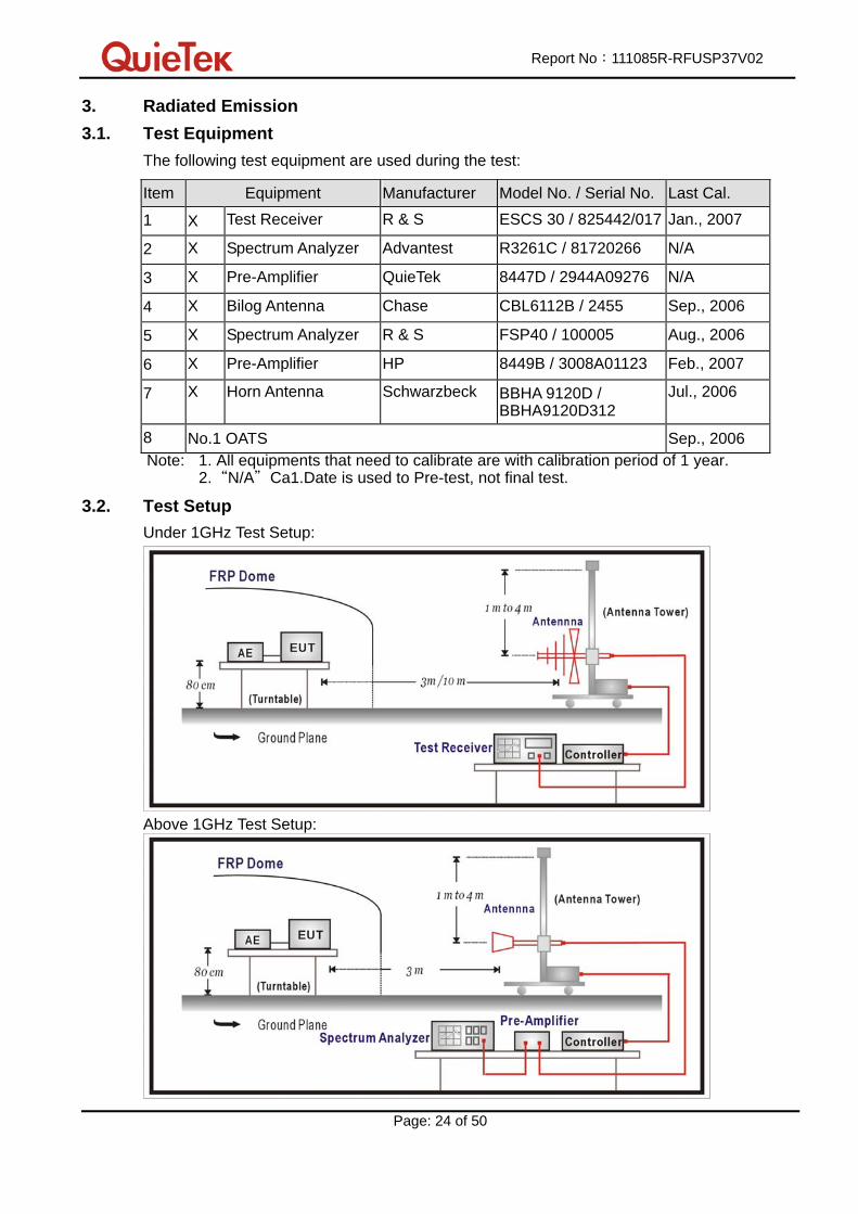
3.1. Test Equipment
The following test equipment are used during the test:
Item Equipment Manufacturer Model No. / Serial No. Last Cal.
1 X Test Receiver R & S ESCS 30 / 825442/017 Jan., 2007
2 X Spectrum Analyzer Advantest R3261C / 81720266 N/A
3 X Pre-Amplifier QuieTek 8447D / 2944A09276 N/A
4 X Bilog Antenna Chase CBL6112B / 2455 Sep., 2006
5 X Spectrum Analyzer R & S FSP40 / 100005 Aug., 2006
6 X Pre-Amplifier HP 8449B / 3008A01123 Feb., 2007
7 X Horn Antenna Schwarzbeck BBHA 9120D / BBHA9120D312
Jul., 2006
8 No.1 OATS Sep., 2006 Note: 1. All equipments that need to calibrate are with calibration period of 1 year.
2.“N/A"Ca1.Date is used to Pre-test, not final test.
3.2. Test Setup
Under 1GHz Test Setup:
Above 1GHz Test Setup:

Report No:111085R-RFUSP37V02
Page: 25 of 50
3.3. Limits
CISPR 22 Limits (dBuV/m)
Class A Class B Frequency
MHz Distance
(m) dBuV/m
Distance
(m) dBuV/m
30 – 230 10 40 10 30
230 – 1000 10 47 10 37
Remark: 1. The tighter limit shall apply at the edge between two frequency bands.
2. Distance refers to the distance in meters between the measuring
instrument antenna and the closed point of any part of the device or
system.
3. RF Voltage (dBuV/m) = 20 log RF Voltage (uV/m)
FCC Part 15 Subpart B Paragraph 15.109 Limits
Class A Class B Frequency
MHz Distance
(m) dBuV/m
Distance
(m) dBuV/m
30-88 10 39 3 40
88-216 10 43.5 3 43.5
216-960 10 46.4 3 46
Above 960 10 49.5 3 54
Remark: 1. RF Voltage (dBuV) = 20 log RF Voltage (uV)
2. In the Above Table, the tighter limit applies at the band edges.
3. Distance refers to the distance in meters between the measuring instrument
antenna and the closed point of any part of the device or system.
Carrier current systems used as unintentional radiators or other unintentional radiators
that are designed to conduct their radio frequency emissions via connecting wires or
cables and that operate in the frequency range of 9 KHz to 30 MHz, including devices
that deliver the radio frequency energy to transducers, such as ultrasonic devices not
covered under part 18 of this chapter, shall comply with the radiated emission limits for
intentional radiators provided in §15.209 for the frequency range of 9 KHz to 30 MHz. As
an alternative, carrier current systems used as unintentional radiators and operating in
the frequency range of 525 KHz to 1705 KHz may comply with the radiated emission
limits provided in §15.221(a).

Report No:111085R-RFUSP37V02
Page: 26 of 50
3.4. Test Procedure
Under 30MHz Test:
The EUT and its simulators are placed on a turn table which is 1.0 meter above ground.
The turn table can rotate 360 degrees to determine the position of the maximum electric
field strength. The EUT was positioned such that the distance from antenna to the EUT
was 3 meters.
The antenna which is 1.0 meter above ground. All X-axis, Y-axis and Z-axis polarization
of the antenna are set on measurement.
The bandwidth below 30MHz setting on the field strength meter (R&S Test Receiver
ESCS 30) is 200Hz and above 30MHz is 9 KHz.
The emission limit shown in the above table are based on measurements employing a
CISPR quasi-peak detector except for the frequency bands 9-90KHz, 110-490KHz and
above 1000MHz. Radiated emission limit in these three bands are based on
measurements employing an average detector.
Above 30MHz Test:
The EUT and its simulators are placed on a turn table which is 0.8 meter above ground. The
turn table can rotate 360 degrees to determine the position of the maximum emission level.
The antenna can move up and down between 1 meter and 4 meters to find out the maximum
emission level.
For class A, the EUT was positioned such that the distance from antenna to the EUT was 10
meters for under 1GHz and above 1GHz.
For class B, the EUT was positioned such that the distance from antenna to the EUT was 3 or
10 meters for under 1GHz and 3 meters for above 1GHz.
The bandwidth below 1GHz setting on the field strength meter (R&S Test Receiver ESCS 30)
is 120 KHz and above 1GHz is 1MHz.
Both horizontal and vertical polarization of the antenna are set on measurement. In order to
find the maximum emission.

Report No:111085R-RFUSP37V02
Page: 27 of 50
All of the interface cables must be manipulated according to ANSI C63.4:2009 on radiated
measurement.
For an unintentional radiator, including a digital device, the spectrum shall be investigated
from the lowest radio frequency signal generated or used in the device, without going below
the lowest frequency for which a radiated emission limit is specified, up to the frequency
shown in the folowing table:
Highest frequency generated or used in
the device or on which the device
operates or tunes (MHz)
Upper frequency of measurement
range (MHz)
Below 1.705 30
1.705 – 108 1000
108 – 500 2000
500 – 1000 5000
Above 1000 5th harmonic of the highest frequency
or 40 GHz, whichever is lower
On any frequency or frequencies below or equal to 1000 MHz, the limits shown are based on
measuring equipment employing a CISPR quasi-peak detector function and on any frequency
or frequencies above 1000 MHz the radiated limits shown are based upon the use of
measurement instrumentation employing an average detector function. When average
radiated emission measurement are included emission measurement below 1000 MHz, there
also is a limit on the radio frequency emissions, as measured using instrumentation with a
peak detector function, corresponding to 20 dB above the maximum permitted average limit.
3.5. Test Specification
According to FCC Part 15 Subpart B: 2009
3.6. Uncertainty
The measurement uncertainty
30MHz~1GHz as ±3.43dB
1GHz~26.5GHz as ±3.65dB

Report No:111085R-RFUSP37V02
Page: 28 of 50
3.7. Test Result
30MHz-1GHz Spurious:
Site : Site 1 Time : 2007/04/19 - 13:58
Limit : FCC_CLASS_B_03M_QP Margin : 6
EUT: Tablet: Wireless Tablet X860/X861; Dongle: Wireless
Tablet Receiver X860/X861
Probe : FCC_RF_30-1G(200605) - HORIZONTAL
Power : AC 120V/60Hz Note : RX-39 Mode 1: Receive (Tablet)
Frequency
(MHz)
Correct Factor
(dB)
Reading Level
(dBuV)
Measure Level
(dBuV/m)
Margin (dB) Limit
(dBuV/m)
Detector Type
1 * 41.663 -1.896 27.886 25.990 -14.010 40.000 QUASI-PEAK
2 269.098 -7.085 28.811 21.725 -24.275 46.000 QUASI-PEAK
3 393.507 0.407 27.318 27.725 -18.275 46.000 QUASI-PEAK
4 580.120 5.369 24.294 29.663 -16.337 46.000 QUASI-PEAK
5 739.519 4.223 25.829 30.053 -15.947 46.000 QUASI-PEAK
6 838.657 3.956 26.933 30.890 -15.110 46.000 QUASI-PEAK
Note:
1. All Reading Levels are Quasi-Peak value.
2. “ * ”, means this data is the worst emission level.
3. Measurement Level = Reading Level + Correct Factor.

Report No:111085R-RFUSP37V02
Page: 29 of 50
Site : Site 1 Time : 2007/04/19 - 13:58
Limit : FCC_CLASS_B_03M_QP Margin : 6
EUT: Tablet: Wireless Tablet X860/X861; Dongle: Wireless
Tablet Receiver X860/X861
Probe : FCC_RF_30-1G(200605) - VERTICAL
Power : AC 120V/60Hz Note : RX39- Mode 1: Receive (Tablet)
Frequency
(MHz)
Correct Factor
(dB)
Reading Level
(dBuV)
Measure Level
(dBuV/m)
Margin (dB) Limit
(dBuV/m)
Detector Type
1 37.776 -4.390 31.627 27.236 -12.764 40.000 QUASI-PEAK
2 203.006 -3.127 25.085 21.958 -21.542 43.500 QUASI-PEAK
3 411.002 -0.198 25.315 25.116 -20.884 46.000 QUASI-PEAK
4 587.896 2.684 25.693 28.377 -17.623 46.000 QUASI-PEAK
5 784.228 5.488 25.237 30.725 -15.275 46.000 QUASI-PEAK
6 * 939.740 9.014 24.922 33.936 -12.064 46.000 QUASI-PEAK
Note:
1. All Reading Levels are Quasi-Peak value.
2. “ * ”, means this data is the worst emission level.
3. Measurement Level = Reading Level + Correct Factor.

Report No:111085R-RFUSP37V02
Page: 30 of 50
Site : Site 1 Time : 2007/04/19 - 14:03
Limit : FCC_CLASS_B_03M_QP Margin : 6
EUT: Tablet: Wireless Tablet X860/X861; Dongle: Wireless
Tablet Receiver X860/X861
Probe : FCC_RF_30-1G(200605) - HORIZONTAL
Power : AC 120V/60Hz Note : RX-39 Mode 2: Receive (Dongle)
Frequency
(MHz)
Correct Factor
(dB)
Reading Level
(dBuV)
Measure Level
(dBuV/m)
Margin (dB) Limit
(dBuV/m)
Detector Type
1 249.659 -8.916 40.498 31.583 -14.417 46.000 QUASIPEAK
2 399.339 1.121 31.528 32.649 -13.351 46.000 QUASIPEAK
3 461.543 2.325 29.856 32.181 -13.819 46.000 QUASIPEAK
4 * 566.513 4.251 31.985 36.236 -9.764 46.000 QUASIPEAK
5 751.182 3.516 28.144 31.660 -14.340 46.000 QUASIPEAK
6 875.591 5.426 29.098 34.524 -11.476 46.000 QUASIPEAK
Note:
1. All Reading Levels are Quasi-Peak value.
2. “ * ”, means this data is the worst emission level.
3. Measurement Level = Reading Level + Correct Factor.

Report No:111085R-RFUSP37V02
Page: 31 of 50
Site : Site 1 Time : 2007/04/19 - 14:02
Limit : FCC_CLASS_B_03M_QP Margin : 6
EUT: Tablet: Wireless Tablet X860/X861; Dongle: Wireless
Tablet Receiver X860/X861
Probe : FCC_RF_30-1G(200605) - VERTICAL
Power : AC 120V/60Hz Note : RX-39 Mode 2: Receive (Dongle)
Frequency
(MHz)
Correct Factor
(dB)
Reading Level
(dBuV)
Measure Level
(dBuV/m)
Margin (dB) Limit
(dBuV/m)
Detector Type
1 107.756 -0.691 30.885 30.194 -13.306 43.500 QUASIPEAK
2 203.006 -3.127 32.502 29.375 -14.125 43.500 QUASIPEAK
3 300.200 -8.515 40.857 32.342 -13.658 46.000 QUASIPEAK
4 564.569 2.234 31.196 33.430 -12.570 46.000 QUASIPEAK
5 751.182 1.935 31.442 33.377 -12.623 46.000 QUASIPEAK
6 * 933.908 7.251 32.140 39.391 -6.609 46.000 QUASIPEAK
Note:
1. All Reading Levels are Quasi-Peak value.
2. “ * ”, means this data is the worst emission level.
3. Measurement Level = Reading Level + Correct Factor.

Report No:111085R-RFUSP37V02
Page: 32 of 50
Above 1 GHz Spurious:
Site : Site 1 Time : 2007/04/20 - 15:08
Limit : FCC_B_(Above_1G)_3M_PK Margin : 6
EUT: Tablet: Wireless Tablet X860/X861; Dongle: Wireless
Tablet Receiver X860/X861
Probe : FCC_RF_1G-18G(2005-3) - HORIZONTAL
Power : AC 120V/60Hz Note : RX-01Mode 1: Receive (Tablet)
Frequency
(MHz)
Correct Factor
(dB)
Reading Level
(dBuV)
Measure Level
(dBuV/m)
Margin (dB) Limit
(dBuV/m)
Detector Type
1 2404.290 -2.592 34.570 31.978 -42.022 74.000 PEAK
2 4808.300 3.622 34.750 38.372 -35.628 74.000 PEAK
3 7212.220 8.698 33.250 41.948 -32.052 74.000 PEAK
4 * 9616.490 12.690 36.100 48.790 -25.210 74.000 PEAK
5 12020.310 11.698 30.070 41.767 -32.233 74.000 PEAK
Note:
1. All Readings below 1GHz are Quasi-Peak, above are performed with peak and/or average measurements as necessary.
2. “ * ”, means this data is the worst emission level. 3. Measurement Level = Reading Level + Correct Factor. 4. The average measurement was not performed when the peak measured data under the limit
of average detection. If the readings given are average, peak measurement should also be supplied.

Report No:111085R-RFUSP37V02
Page: 33 of 50
Site : Site 1 Time : 2007/04/20 - 15:10
Limit : FCC_B_(Above_1G)_3M_PK Margin : 6
EUT: Tablet: Wireless Tablet X860/X861; Dongle: Wireless
Tablet Receiver X860/X861
Probe : FCC_RF_1G-18G(2005-3) - VERTICAL
Power : AC 120V/60Hz Note : RX-01 Mode 1: Receive (Tablet)
Frequency
(MHz)
Correct Factor
(dB)
Reading Level
(dBuV)
Measure Level
(dBuV/m)
Margin (dB) Limit
(dBuV/m)
Detector Type
1 2404.050 -4.192 36.170 31.977 -42.023 74.000 PEAK
2 4808.160 1.842 36.990 38.831 -35.169 74.000 PEAK
3 7212.010 8.663 33.020 41.683 -32.317 74.000 PEAK
4 * 9616.200 14.687 35.320 50.007 -23.993 74.000 PEAK
5 12020.290 16.704 30.990 47.693 -26.307 74.000 PEAK
Note:
1. All Readings below 1GHz are Quasi-Peak, above are performed with peak and/or average measurements as necessary.
2. “ * ”, means this data is the worst emission level. 3. Measurement Level = Reading Level + Correct Factor. 4. The average measurement was not performed when the peak measured data under the limit
of average detection. If the readings given are average, peak measurement should also be supplied.

Report No:111085R-RFUSP37V02
Page: 34 of 50
Site : Site 1 Time : 2007/04/20 - 15:11
Limit : FCC_B_(Above_1G)_3M_PK Margin : 6
EUT: Tablet: Wireless Tablet X860/X861; Dongle: Wireless
Tablet Receiver X860/X861
Probe : FCC_RF_1G-18G(2005-3) - HORIZONTAL
Power : AC 120V/60Hz Note : RX39-Mode 1: Receive (Tablet)
Frequency
(MHz)
Correct Factor
(dB)
Reading Level
(dBuV)
Measure Level
(dBuV/m)
Margin (dB) Limit
(dBuV/m)
Detector Type
1 2442.220 -2.441 35.200 32.760 -41.240 74.000 PEAK
2 4884.200 4.158 34.700 38.858 -35.142 74.000 PEAK
3 7326.400 8.863 33.400 42.263 -31.737 74.000 PEAK
4 * 9768.610 13.242 35.510 48.752 -25.248 74.000 PEAK
5 12104.800 18.196 30.510 48.706 -25.294 74.000 PEAK
Note:
1. All Readings below 1GHz are Quasi-Peak, above are performed with peak and/or average measurements as necessary.
2. “ * ”, means this data is the worst emission level. 3. Measurement Level = Reading Level + Correct Factor. 4. The average measurement was not performed when the peak measured data under the limit
of average detection. If the readings given are average, peak measurement should also be supplied.

Report No:111085R-RFUSP37V02
Page: 35 of 50
Site : Site 1 Time : 2007/04/20 - 15:12
Limit : FCC_B_(Above_1G)_3M_PK Margin : 6
EUT: Tablet: Wireless Tablet X860/X861; Dongle: Wireless
Tablet Receiver X860/X861
Probe : FCC_RF_1G-18G(2005-3) - VERTICAL
Power : AC 120V/60Hz Note : RX39-Mode 1: Receive (Tablet)
Frequency
(MHz)
Correct Factor
(dB)
Reading Level
(dBuV)
Measure Level
(dBuV/m)
Margin (dB) Limit
(dBuV/m)
Detector Type
1 2442.030 -4.041 35.180 31.140 -42.860 74.000 PEAK
2 4884.180 2.522 35.380 37.902 -36.098 74.000 PEAK
3 7326.060 8.862 33.270 42.132 -31.868 74.000 PEAK
4 * 9768.330 15.241 35.720 50.961 -23.039 74.000 PEAK
5 12210.450 19.507 30.660 50.167 -23.833 74.000 PEAK
Note:
1. All Readings below 1GHz are Quasi-Peak, above are performed with peak and/or average measurements as necessary.
2. “ * ”, means this data is the worst emission level. 3. Measurement Level = Reading Level + Correct Factor. 4. The average measurement was not performed when the peak measured data under the limit
of average detection. If the readings given are average, peak measurement should also be supplied.

Report No:111085R-RFUSP37V02
Page: 36 of 50
Site : Site 1 Time : 2007/04/20 - 15:14
Limit : FCC_B_(Above_1G)_3M_PK Margin : 6
EUT: Tablet: Wireless Tablet X860/X861; Dongle: Wireless
Tablet Receiver X860/X861
Probe : FCC_RF_1G-18G(2005-3) - HORIZONTAL
Power : AC 120V/60Hz Note : RX78-Mode 1: Receive (Tablet)
Frequency
(MHz)
Correct Factor
(dB)
Reading Level
(dBuV)
Measure Level
(dBuV/m)
Margin (dB) Limit
(dBuV/m)
Detector Type
1 2481.110 -2.262 34.970 32.709 -41.291 74.000 PEAK
2 4962.210 4.400 35.170 39.570 -34.430 74.000 PEAK
3 7443.210 9.020 32.840 41.860 -32.140 74.000 PEAK
4 * 9924.560 14.586 36.900 51.486 -22.514 74.000 PEAK
5 12405.260 21.126 29.830 50.956 -23.044 74.000 PEAK
Note:
1. All Readings below 1GHz are Quasi-Peak, above are performed with peak and/or average measurements as necessary.
2. “ * ”, means this data is the worst emission level. 3. Measurement Level = Reading Level + Correct Factor. 4. The average measurement was not performed when the peak measured data under the limit
of average detection. If the readings given are average, peak measurement should also be supplied.

Report No:111085R-RFUSP37V02
Page: 37 of 50
Site : Site 1 Time : 2007/04/20 - 15:15
Limit : FCC_B_(Above_1G)_3M_PK Margin : 6
EUT: Tablet: Wireless Tablet X860/X861; Dongle: Wireless
Tablet Receiver X860/X861
Probe : FCC_RF_1G-18G(2005-3) - VERTICAL
Power : AC 120V/60Hz Note : RX78-Mode 1: Receive (Tablet)
Frequency
(MHz)
Correct Factor
(dB)
Reading Level
(dBuV)
Measure Level
(dBuV/m)
Margin (dB) Limit
(dBuV/m)
Detector Type
1 2481.210 -3.861 34.570 30.709 -43.291 74.000 PEAK
2 4961.960 2.922 35.680 38.602 -35.398 74.000 PEAK
3 7443.210 9.020 34.740 43.760 -30.240 74.000 PEAK
4 * 9924.360 15.340 35.830 51.170 -22.830 74.000 PEAK
5 12405.310 16.116 30.810 46.926 -27.074 74.000 PEAK
Note:
1. All Readings below 1GHz are Quasi-Peak, above are performed with peak and/or average measurements as necessary.
2. “ * ”, means this data is the worst emission level. 3. Measurement Level = Reading Level + Correct Factor. 4. The average measurement was not performed when the peak measured data under the limit
of average detection. If the readings given are average, peak measurement should also be supplied.

Report No:111085R-RFUSP37V02
Page: 38 of 50
Site : Site 1 Time : 2007/04/20 - 15:23
Limit : FCC_B_(Above_1G)_3M_PK Margin : 6
EUT: Tablet: Wireless Tablet X860/X861; Dongle: Wireless
Tablet Receiver X860/X861
Probe : FCC_RF_1G-18G(2005-3) - HORIZONTAL
Power : AC 120V/60Hz Note : RX01-Mode 2: Receive (Dongle)
Frequency
(MHz)
Correct Factor
(dB)
Reading Level
(dBuV)
Measure Level
(dBuV/m)
Margin (dB) Limit
(dBuV/m)
Detector Type
1 2404.360 -2.592 36.210 33.619 -40.381 74.000 PEAK
2 4808.240 3.622 37.230 40.852 -33.148 74.000 PEAK
3 7212.520 8.699 33.250 41.949 -32.051 74.000 PEAK
4 * 9616.540 12.690 33.420 46.110 -27.890 74.000 PEAK
5 12020.540 11.717 30.890 42.607 -31.393 74.000 PEAK
Note:
1. All Readings below 1GHz are Quasi-Peak, above are performed with peak and/or average measurements as necessary.
2. “ * ”, means this data is the worst emission level. 3. Measurement Level = Reading Level + Correct Factor. 4. The average measurement was not performed when the peak measured data under the limit
of average detection. If the readings given are average, peak measurement should also be supplied.

Report No:111085R-RFUSP37V02
Page: 39 of 50
Site : Site 1 Time : 2007/04/20 - 15:25
Limit : FCC_B_(Above_1G)_3M_PK Margin : 6
EUT: Tablet: Wireless Tablet X860/X861; Dongle: Wireless
Tablet Receiver X860/X861
Probe : FCC_RF_1G-18G(2005-3) - VERTICAL
Power : AC 120V/60Hz Note : RX01-Mode 2: Receive (Dongle)
Frequency
(MHz)
Correct Factor
(dB)
Reading Level
(dBuV)
Measure Level
(dBuV/m)
Margin (dB) Limit
(dBuV/m)
Detector Type
1 2404.360 -4.192 35.260 31.069 -42.931 74.000 PEAK
2 4808.320 1.843 34.350 36.193 -37.807 74.000 PEAK
3 7212.360 8.665 32.800 41.465 -32.535 74.000 PEAK
4 * 9616.380 14.687 33.070 47.757 -26.243 74.000 PEAK
5 12010.400 16.610 30.490 47.100 -26.900 74.000 PEAK
Note:
1. All Readings below 1GHz are Quasi-Peak, above are performed with peak and/or average measurements as necessary.
2. “ * ”, means this data is the worst emission level. 3. Measurement Level = Reading Level + Correct Factor. 4. The average measurement was not performed when the peak measured data under the limit
of average detection. If the readings given are average, peak measurement should also be supplied.

Report No:111085R-RFUSP37V02
Page: 40 of 50
Site : Site 1 Time : 2007/04/20 - 15:26
Limit : FCC_B_(Above_1G)_3M_PK Margin : 6
EUT: Tablet: Wireless Tablet X860/X861; Dongle: Wireless
Tablet Receiver X860/X861
Probe : FCC_RF_1G-18G(2005-3) - HORIZONTAL
Power : AC 120V/60Hz Note : RX39-Mode 2: Receive (Dongle)
Frequency
(MHz)
Correct Factor
(dB)
Reading Level
(dBuV)
Measure Level
(dBuV/m)
Margin (dB) Limit
(dBuV/m)
Detector Type
1 2442.292 -2.440 35.310 32.870 -41.130 74.000 PEAK
2 4884.250 4.158 36.790 40.948 -33.052 74.000 PEAK
3 7326.480 8.863 33.460 42.323 -31.677 74.000 PEAK
4 9768.520 13.242 34.590 47.832 -26.168 74.000 PEAK
5 * 12210.460 17.430 30.510 47.940 -26.060 74.000 PEAK
Note:
1. All Readings below 1GHz are Quasi-Peak, above are performed with peak and/or average measurements as necessary.
2. “ * ”, means this data is the worst emission level. 3. Measurement Level = Reading Level + Correct Factor. 4. The average measurement was not performed when the peak measured data under the limit
of average detection. If the readings given are average, peak measurement should also be supplied.
Report No:111085R-RFUSP37V02
Page: 41 of 50
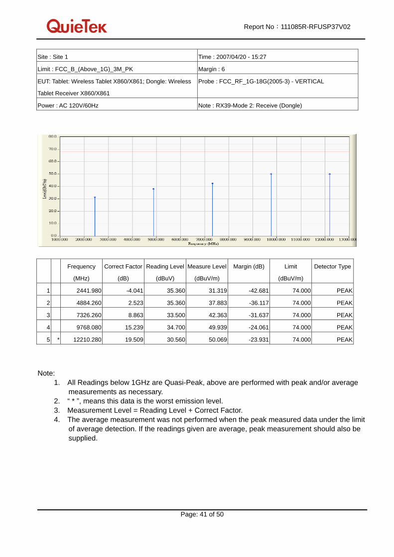
Site : Site 1 Time : 2007/04/20 - 15:27
Limit : FCC_B_(Above_1G)_3M_PK Margin : 6
EUT: Tablet: Wireless Tablet X860/X861; Dongle: Wireless
Tablet Receiver X860/X861
Probe : FCC_RF_1G-18G(2005-3) - VERTICAL
Power : AC 120V/60Hz Note : RX39-Mode 2: Receive (Dongle)
Frequency
(MHz)
Correct Factor
(dB)
Reading Level
(dBuV)
Measure Level
(dBuV/m)
Margin (dB) Limit
(dBuV/m)
Detector Type
1 2441.980 -4.041 35.360 31.319 -42.681 74.000 PEAK
2 4884.260 2.523 35.360 37.883 -36.117 74.000 PEAK
3 7326.260 8.863 33.500 42.363 -31.637 74.000 PEAK
4 9768.080 15.239 34.700 49.939 -24.061 74.000 PEAK
5 * 12210.280 19.509 30.560 50.069 -23.931 74.000 PEAK
Note:
1. All Readings below 1GHz are Quasi-Peak, above are performed with peak and/or average measurements as necessary.
2. “ * ”, means this data is the worst emission level. 3. Measurement Level = Reading Level + Correct Factor. 4. The average measurement was not performed when the peak measured data under the limit
of average detection. If the readings given are average, peak measurement should also be supplied.

Report No:111085R-RFUSP37V02
Page: 42 of 50
Site : Site 1 Time : 2007/04/20 - 15:28
Limit : FCC_B_(Above_1G)_3M_PK Margin : 6
EUT: Tablet: Wireless Tablet X860/X861; Dongle: Wireless
Tablet Receiver X860/X861
Probe : FCC_RF_1G-18G(2005-3) - HORIZONTAL
Power : AC 120V/60Hz Note : RX78-Mode 2: Receive (Dongle)
Frequency
(MHz)
Correct Factor
(dB)
Reading Level
(dBuV)
Measure Level
(dBuV/m)
Margin (dB) Limit
(dBuV/m)
Detector Type
1 2481.220 -2.261 34.690 32.429 -41.571 74.000 PEAK
2 4962.100 4.400 39.150 43.550 -30.450 74.000 PEAK
3 7443.180 9.020 32.920 41.940 -32.060 74.000 PEAK
4 9924.630 14.586 35.770 50.356 -23.644 74.000 PEAK
5 * 12405.610 21.158 31.270 52.427 -21.573 74.000 PEAK
Note:
1. All Readings below 1GHz are Quasi-Peak, above are performed with peak and/or average measurements as necessary.
2. “ * ”, means this data is the worst emission level. 3. Measurement Level = Reading Level + Correct Factor. 4. The average measurement was not performed when the peak measured data under the limit
of average detection. If the readings given are average, peak measurement should also be supplied.

Report No:111085R-RFUSP37V02
Page: 43 of 50
Site : Site 1 Time : 2007/04/20 - 15:30
Limit : FCC_B_(Above_1G)_3M_PK Margin : 6
EUT: Tablet: Wireless Tablet X860/X861; Dongle: Wireless
Tablet Receiver X860/X861
Probe : FCC_RF_1G-18G(2005-3) - VERTICAL
Power : AC 120V/60Hz Note : RX78-Mode 2: Receive (Dongle)
Frequency
(MHz)
Correct Factor
(dB)
Reading Level
(dBuV)
Measure Level
(dBuV/m)
Margin (dB) Limit
(dBuV/m)
Detector Type
1 2481.220 -3.861 34.600 30.739 -43.261 74.000 PEAK
2 4962.160 2.922 36.600 39.522 -34.478 74.000 PEAK
3 7443.260 9.020 33.030 42.050 -31.950 74.000 PEAK
4 * 9924.710 15.340 33.620 48.960 -25.040 74.000 PEAK
5 12405.210 16.117 29.760 45.877 -28.123 74.000 PEAK
Note:
1. All Readings below 1GHz are Quasi-Peak, above are performed with peak and/or average measurements as necessary.
2. “ * ”, means this data is the worst emission level. 3. Measurement Level = Reading Level + Correct Factor.
4. The average measurement was not performed when the peak measured data under the limit
of average detection. If the readings given are average, peak measurement should also be
supplied.

Report No:111085R-RFUSP37V02
Page: 44 of 50
3.8. Test Photo
Test Mode : Mode 1: Receive (Tablet) Description: Front View of Radiated Emission Test Setup (Bi-Log)
Test Mode : Mode 1: Receive (Tablet) Description: Back View of Radiated Emission Test Setup (Bi-Log)

Report No:111085R-RFUSP37V02
Page: 45 of 50
Test Mode : Mode 1: Receive (Tablet) Description: Front View of Radiated Emission Test Setup (Horn)
Report No:111085R-RFUSP37V02
Page: 46 of 50
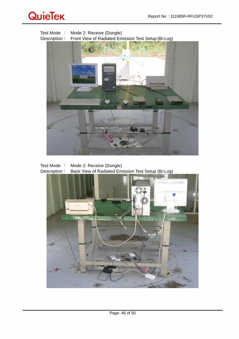
Test Mode : Mode 2: Receive (Dongle) Description: Front View of Radiated Emission Test Setup (Bi-Log)
Test Mode : Mode 2: Receive (Dongle) Description: Back View of Radiated Emission Test Setup (Bi-Log)

Report No:111085R-RFUSP37V02
Page: 47 of 50
Test Mode : Mode 2: Receive (Dongle) Description: Front View of Radiated Emission Test Setup (Horn)

Report No:111085R-RFUSP37V02
Page: 48 of 50
Attachement
EUT Photograph
(1) EUT Photo (Tablet)
(2) EUT Photo

Report No:111085R-RFUSP37V02
Page: 49 of 50
(3) EUT Photo (Dongle)
(4) EUT Photo

Report No:111085R-RFUSP37V02
Page: 50 of 50
Reference : Laboratory of License


