12. deflections of beams and shafts - ksu...
TRANSCRIPT

12. Deflections of Beams and ShaftsCHAPTER OBJECTIVES
• Use various methods to determine the deflection and slope at specific pts on beams and shafts:1 Integration method1. Integration method2. Discontinuity functions3 Method of3. Method of
superposition4. Moment-area method4. Moment area method
©2005 Pearson Education South Asia Pte Ltd 1

12. Deflections of Beams and Shafts12.1 THE ELASTIC CURVE
• It is useful to sketch the deflected shape of the loaded beam, to “visualize” computed results andloaded beam, to visualize computed results and partially check the results.
• The deflection diagram of the longitudinal axis that g gpasses through the centroid of each x-sectional area of the beam is called the elastic curve.
©2005 Pearson Education South Asia Pte Ltd 2

12. Deflections of Beams and Shafts12.1 THE ELASTIC CURVE
• Draw the moment diagram for the beam first beforefor the beam first before creating the elastic curve.
• Use beam convention as shown and established in chapter 6.1.
©2005 Pearson Education South Asia Pte Ltd 3

12. Deflections of Beams and Shafts12.1 THE ELASTIC CURVE
• For example, due to roller and pin supports at B and D, displacements at B and D is zero.For region of ve• For region of -ve moment AC, elastic curve concave downwards.
• Within region of +ve moment CD, elastic curve
dconcave upwards.• At pt C, there is an inflection pt where curve
changes from concave up to concave down (zero
©2005 Pearson Education South Asia Pte Ltd 4
changes from concave up to concave down (zero moment).

12. Deflections of Beams and Shafts12.1 THE ELASTIC CURVE
©2005 Pearson Education South Asia Pte Ltd 5

12. Deflections of Beams and Shafts12.1 THE ELASTIC CURVE
Moment-Curvature Relationship• x axis extends +ve to the
right, along longitudinal axis of beam.A differential element of ndeformed idth• A differential element of undeformed widthdx is located.
• ν axis extends +ve upwards from x axisν axis extends +ve upwards from x axis. It measures the displacement of the centroid on x-sectional area of element.
• A “localized” y coordinate is specified for the position of a fiber in the element. It i d + d f th t l i
©2005 Pearson Education South Asia Pte Ltd 6
• It is measured +ve upward from the neutral axis.
12. Deflections of Beams and Shafts12.1 THE ELASTIC CURVE
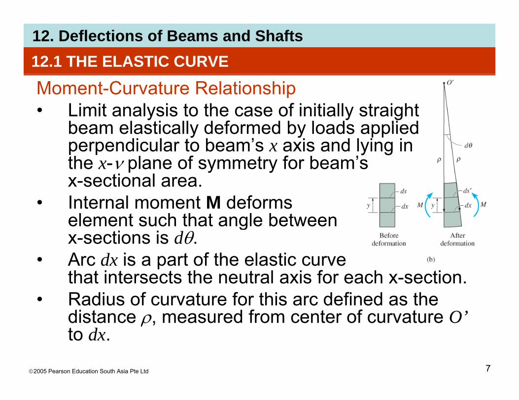
Moment-Curvature Relationship• Limit analysis to the case of initially straight
beam elastically deformed by loads appliedbeam elastically deformed by loads applied perpendicular to beam’s x axis and lying in the x-ν plane of symmetry for beam’s
ti lx-sectional area.• Internal moment M deforms
element such that angle betweenelement such that angle between x-sections is dθ.
• Arc dx is a part of the elastic curve that intersects the neutral axis for each x sectionthat intersects the neutral axis for each x-section.
• Radius of curvature for this arc defined as the distance ρ, measured from center of curvature O’
©2005 Pearson Education South Asia Pte Ltd 7
ρto dx.

12. Deflections of Beams and Shafts12.1 THE ELASTIC CURVE
Moment-Curvature Relationship• Strain in arc ds, at position y from neutral axis, is
'ds
dsdsε −=
( )( )[ ]
'ddy
dydsddxdsds
θρθρθρθρ
−−−=== andBut
( )[ ]
( )1d
ddy s
εθρ
θρθρε = or
( )1-121yε
ρ−=
©2005 Pearson Education South Asia Pte Ltd 8

12. Deflections of Beams and Shafts12.1 THE ELASTIC CURVE
Moment-Curvature Relationship• If material is homogeneous and shows linear-
elastic behavior, Hooke’s law applies. Since flexure formula also applies, we combing the equations to getq gε=σ/E , σ=-My/I ( )2-121
EIM
=ρ
ρ = radius of curvature at a specific pt on elastic curve (1/ρ is referred to as the curvature).
M = internal moment in beam at pt where is to beM internal moment in beam at pt where is to be determined.
E = material’s modulus of elasticity.
©2005 Pearson Education South Asia Pte Ltd 9
I = beam’s moment of inertia computed about neutral axis.

12. Deflections of Beams and Shafts12.1 THE ELASTIC CURVE
Moment-Curvature Relationship• EI is the flexural rigidity and is always positive.• Sign for ρ depends on the direction of the
moment.• As shown when M is +ve ρ extends above theAs shown, when M is +ve, ρ extends above the
beam. When M is –ve, ρ extends below the beam.
©2005 Pearson Education South Asia Pte Ltd 10

12. Deflections of Beams and Shafts12.1 THE ELASTIC CURVE
Moment-Curvature Relationship• Using flexure formula, σ = −My/I, curvature is also
( )3-121Eyσ
ρ−=
• Eqns 12-2 and 12-3 valid for either small or large radii of curvature.
©2005 Pearson Education South Asia Pte Ltd 11

12. Deflections of Beams and Shafts12.2 SLOPE AND DISPLACEMENT BY INTEGRATION
• Let’s represent the curvature in terms of ν and x.2d υ
( ) 23
2
2
1
1
⎥⎤
⎢⎡ +
=d
dx
υρ
• Substitute into Eqn 12-2
( )1 ⎥⎦⎢⎣+ dx
dυ
Substitute into Eqn 12 2
( )4122
2Mdx
d υ
( )( )4-12
12
32 EI
dxd
dx =
⎥⎦⎤
⎢⎣⎡ + υ
©2005 Pearson Education South Asia Pte Ltd 12
dx ⎥⎦⎢⎣

12. Deflections of Beams and Shafts12.2 SLOPE AND DISPLACEMENT BY INTEGRATION
• Most engineering codes specify limitations on deflections for tolerance or aesthetic purposes.Slope of elastic curve determined from d /d is• Slope of elastic curve determined from dν/dx is very small and its square will be negligible compared with unity.
• Therefore, by approximation 1/ρ = d2ν /dx2, Eqn12-4 rewritten as
( )5-122 Md =υ
• Differentiate each side w.r.t. x and substitute
( )5122 EIdx=
V = dM/dx, we get
( ) ( )6-122
2xVdEId
=⎞
⎜⎜⎛ υ
©2005 Pearson Education South Asia Pte Ltd 13
( ) ( )6122 xVdx
EIdx ⎠⎜⎝

12. Deflections of Beams and Shafts12.2 SLOPE AND DISPLACEMENT BY INTEGRATION
• Differentiating again, using −w = dV/dx yields
( ) ( )71222 dEId ⎞
⎜⎛ υ
• Flexural rigidity is constant along beam thus
( ) ( )7-1222 xwdx
EIdx
−=⎟⎠
⎜⎜⎝
• Flexural rigidity is constant along beam, thus
( ) ( )8-124
xwdEI −=υ ( ) ( )8124 xwdx
EI =
( ) ( )9123
xVdEI υ ( ) ( )9-123 xVdx
EI =
( )1012)(2
MdEI υ
©2005 Pearson Education South Asia Pte Ltd 14
( )10-12)(2 xMdxdEI =υ

12. Deflections of Beams and Shafts12.2 SLOPE AND DISPLACEMENT BY INTEGRATION
• Generally, it is easier to determine the internal moment M as a function of x, integrate twice, and evaluate only two integration constantsevaluate only two integration constants.
• For convenience in writing each moment expression, the origin for each x coordinate can be p , gselected arbitrarily.
Sign convention and coordinatesUse the proper signs for M V and• Use the proper signs for M, V and w.
©2005 Pearson Education South Asia Pte Ltd 15

12. Deflections of Beams and Shafts12.2 SLOPE AND DISPLACEMENT BY INTEGRATION
• Positive deflection v is upward.
• Positive slope angle θ will be measured counterclockwise when x is positive to the rightcounterclockwise when x is positive to the right.
• Positive slope angle θ will be measured clockwise• Positive slope angle θ will be measured clockwise when x is positive to the left.
©2005 Pearson Education South Asia Pte Ltd 16

12. Deflections of Beams and Shafts12.2 SLOPE AND DISPLACEMENT BY INTEGRATION
©2005 Pearson Education South Asia Pte Ltd 17

12. Deflections of Beams and Shafts12.2 SLOPE AND DISPLACEMENT BY INTEGRATION
Boundary and continuity conditions• Possible boundary
conditions areconditions are shown here.
©2005 Pearson Education South Asia Pte Ltd 18

12. Deflections of Beams and Shafts12.2 SLOPE AND DISPLACEMENT BY INTEGRATION
Boundary and continuity conditions• If a single x coordinate cannot be used to express
the eqn for beam’s slope or elastic curve thenthe eqn for beam’s slope or elastic curve, then continuity conditions must be used to evaluate some of the integration constants.
0≤ x1 ≤a , a ≤x2 ≤(a+b)
θ1 ( ) θ2 ( )θ1 (a) = θ2 (a)v1 (a) = v2 (a)
0≤ x1 ≤a , 0 ≤x2 ≤b
©2005 Pearson Education South Asia Pte Ltd 19
θ1 (a) = - θ2 (b)v1 (a) = v2 (b)

12. Deflections of Beams and Shafts12.2 SLOPE AND DISPLACEMENT BY INTEGRATION
Procedure for analysisElastic curve• Draw an exaggerated view of the beam’s elastic
curve. • Recall that zero slope and zero displacementRecall that zero slope and zero displacement
occur at all fixed supports, and zero displacement occurs at all pin and roller supports.Establish the and coordinate a es• Establish the x and ν coordinate axes.
• The x axis must be parallel to the undeflected beam and can have an origin at any pt along the g y p gbeam, with +ve direction either to the right or to the left.
©2005 Pearson Education South Asia Pte Ltd 20

12. Deflections of Beams and Shafts12.2 SLOPE AND DISPLACEMENT BY INTEGRATION
Procedure for analysisElastic curve• If several discontinuous loads are present,
establish x coordinates that are valid for each region of the beam between the discontinuties. g
• Choose these coordinates so that they will simplify subsequent algrebraic work.
©2005 Pearson Education South Asia Pte Ltd 21

12. Deflections of Beams and Shafts12.2 SLOPE AND DISPLACEMENT BY INTEGRATION
Procedure for analysisLoad or moment functionLoad or moment function• For each region in which there is an x coordinate,
express that loading w or the internal moment Mp gas a function of x.
• In particular, always assume that M acts in the y+ve direction when applying the eqn of moment equilibrium to determine M = f(x).
©2005 Pearson Education South Asia Pte Ltd 22

12. Deflections of Beams and Shafts12.2 SLOPE AND DISPLACEMENT BY INTEGRATION
Procedure for analysisSlope and elastic curve• Provided EI is constant, apply either the load eqn
EI d4ν/dx4 = −w(x), which requires four integrations to get ( ) or the moment eqnsto get ν = ν(x), or the moment eqns EI d2ν /dx2 = M(x), which requires only two integrations. For each integration, we include a g g ,constant of integration.
• Constants are evaluated using boundary diti f th t d th ti itconditions for the supports and the continuity
conditions that apply to slope and displacement at pts where two functions meet.
©2005 Pearson Education South Asia Pte Ltd 23
pts where two functions meet.

12. Deflections of Beams and Shafts12.2 SLOPE AND DISPLACEMENT BY INTEGRATIONProcedure for analysisSlope and elastic curve• Once constants are evaluated and substituted
back into slope and deflection eqns, slope and displacement at specific pts on elastic curve candisplacement at specific pts on elastic curve can be determined.
• The numerical values obtained is checked graphically by comparing them with sketch of the elastic curve.R li th t l f l• Realize that +ve values for slope are counterclockwise if the x axis extends +ve to the right, and clockwise if the x axis extends +ve to
©2005 Pearson Education South Asia Pte Ltd 24
right, and clockwise if the x axis extends ve to the left. For both cases, +ve displacement is upwards.
12. Deflections of Beams and ShaftsEXAMPLE 12.1
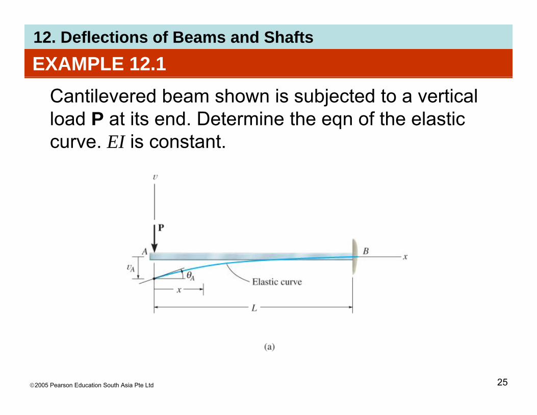
Cantilevered beam shown is subjected to a vertical load P at its end. Determine the eqn of the elastic curve. EI is constant.
©2005 Pearson Education South Asia Pte Ltd 25

12. Deflections of Beams and ShaftsEXAMPLE 12.1 (SOLN)Elastic curve: Load tends to deflect the beam. By inspection, the internal moment can be
t d th h trepresented throughout the beam using a single x coordinatesingle x coordinate.Moment function: From free-body diagram, with Macting in the +ve direction we haveacting in the +ve direction, we have
PxM −=
©2005 Pearson Education South Asia Pte Ltd 26

12. Deflections of Beams and ShaftsEXAMPLE 12.1 (SOLN)
Slope and elastic curve:Applying Eqn 12-10 and integrating twice yieldsApplying Eqn 12-10 and integrating twice yields
( )12
2PxdEI −=υ ( )
( )21
2
2
CPxdEI
dx
+−=υ ( )
( )3
22
3
1
CCPxEI
Cdx
EI
++
+−=
υ ( )36 21 CxCEI ++−=υ
©2005 Pearson Education South Asia Pte Ltd 27
12. Deflections of Beams and ShaftsEXAMPLE 12.1 (SOLN)
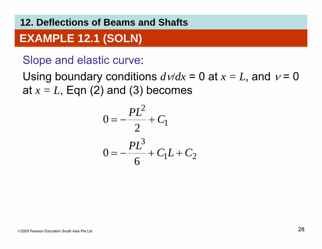
Slope and elastic curve:Using boundary conditions dν/dx = 0 at x = L and ν = 0Using boundary conditions dν/dx = 0 at x = L, and ν = 0 at x = L, Eqn (2) and (3) becomes
2PL
3
1
2
20 CPL +−=
21
3
60 CLCPL ++−=
©2005 Pearson Education South Asia Pte Ltd 28

12. Deflections of Beams and ShaftsEXAMPLE 12.1 (SOLN)Slope and elastic curve:Thus, C1 = PL2/2 and C2 = PL3/3. Substituting theseThus, C1 PL /2 and C2 PL /3. Substituting these results into Eqns (2) and (3) with θ = dν/dx, we get
( )22LPθ ( )
( )323
22
23
2
LxLxP
xLEI
+=
−−=
υ
θ
Maximum slope and displacement occur at A (x = 0)
( )236
LxLxEI
−+−=υ
Maximum slope and displacement occur at A (x 0),
EIPL
EIPL
AA 32
32−== υθ
©2005 Pearson Education South Asia Pte Ltd 29
EIEI 32

12. Deflections of Beams and ShaftsEXAMPLE 12.1 (SOLN)Slope and elastic curve:Positive result for θA indicates counterclockwise Arotation and negative result for A indicates that νA is downward.
Consider beam to have a length of 5 m, support load P = 30 kN and made of A-36 steel havingP 30 kN and made of A 36 steel having Est = 200 GPa.
©2005 Pearson Education South Asia Pte Ltd 30
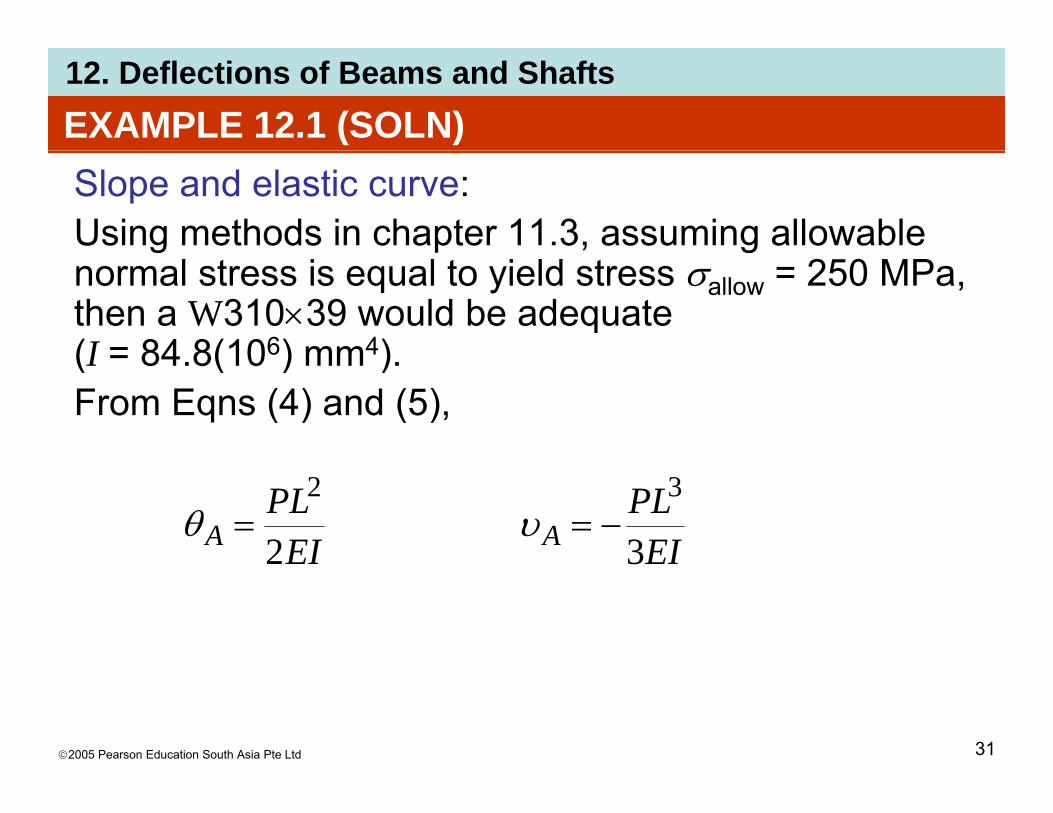
12. Deflections of Beams and ShaftsEXAMPLE 12.1 (SOLN)Slope and elastic curve:Using methods in chapter 11.3, assuming allowable g gnormal stress is equal to yield stress σallow = 250 MPa, then a W310×39 would be adequate (I = 84 8(106) mm4)(I = 84.8(10 ) mm ). From Eqns (4) and (5),
EIPL
EIPL
AA 32
32−== υθ
EIEI 32
©2005 Pearson Education South Asia Pte Ltd 31

12. Deflections of Beams and ShaftsEXAMPLE 12.1 (SOLN)Slope and elastic curve:From Eqns (4) and (5),From Eqns (4) and (5),
( ) ( )mm/m10m5N/kN10kN302233⎥⎤
⎢⎡×( ) ( )
( )[ ] ( )( ) rad0221.0mm108.84N/mm102002
mm/m10m5N/kN10kN30
4623 =⎥⎦⎢⎣
×=Aθ
( ) ( ) 3233 ⎤⎡( ) ( )( )[ ] ( )( ) mm7.73
mm10884N/mm102003
mm/m10m5N/kN10kN30
4623
33
−=⎥⎦⎤
⎢⎣⎡×
−=Aυ
©2005 Pearson Education South Asia Pte Ltd 32
( )[ ] ( )( )mm108.84N/mm102003

12. Deflections of Beams and ShaftsEXAMPLE 12.1 (SOLN)Slope and elastic curve:Since θ2
A = (dν/dx)2 = 0.000488 << 1, this justifies theSince θ A (dν/dx) 0.000488 1, this justifies the use of Eqn 12-10 than the more exact 12-4.
©2005 Pearson Education South Asia Pte Ltd 33

12. Deflections of Beams and ShaftsEXAMPLE 12.1 (SOLN)
SOLUTION 2Using Eqn 12-8 to solve the problem. Here w(x) = 0Using Eqn 12 8 to solve the problem. Here w(x) 0 for 0 ≤ x ≤ L, so that upon integrating once, we get the form of Eqn 12-19
dxdEI =4
40υ
VCddEI
dx
== 13
3'υ
dx3
©2005 Pearson Education South Asia Pte Ltd 34

12. Deflections of Beams and ShaftsEXAMPLE 12.1 (SOLN)Solution IIShear constant C’1 can be evaluated at x = 0, since 1VA = −P. Thus, C’1 = −P. Integrating again yields the form of Eqn 12-10,
3P
dxdEI −=3
3υ
MCPxdxdEI =+−= 22
2'υ
Here, M = 0 at x = 0, so C’2 = 0, and as a result, we obtain Eqn 1 and solution proceeds as before.
©2005 Pearson Education South Asia Pte Ltd 35
q p

12. Deflections of Beams and Shafts
©2005 Pearson Education South Asia Pte Ltd 36
12. Deflections of Beams and Shafts
©2005 Pearson Education South Asia Pte Ltd 37

12. Deflections of Beams and Shafts
©2005 Pearson Education South Asia Pte Ltd 38

12. Deflections of Beams and Shafts
©2005 Pearson Education South Asia Pte Ltd 39

12. Deflections of Beams and Shafts
©2005 Pearson Education South Asia Pte Ltd 40

12. Deflections of Beams and Shafts
©2005 Pearson Education South Asia Pte Ltd 41
12. Deflections of Beams and Shafts
©2005 Pearson Education South Asia Pte Ltd 42
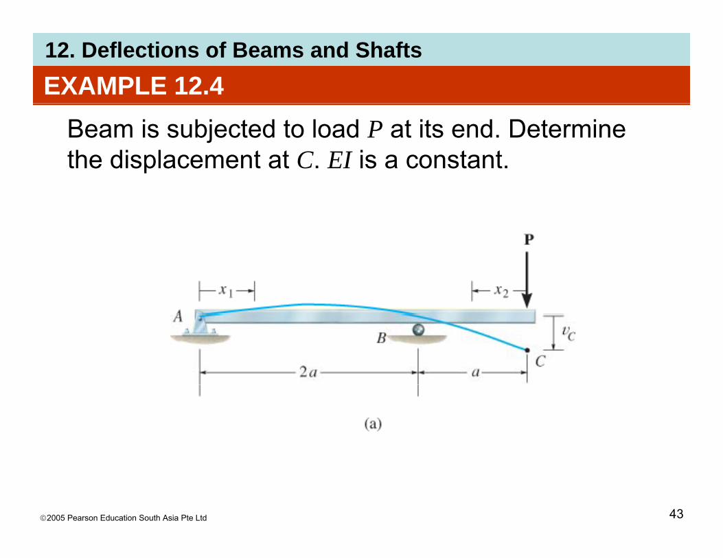
12. Deflections of Beams and ShaftsEXAMPLE 12.4
Beam is subjected to load P at its end. Determine the displacement at C. EI is a constant.
©2005 Pearson Education South Asia Pte Ltd 43

12. Deflections of Beams and ShaftsEXAMPLE 12.4 (SOLN)Elastic curveBeam deflects into shape shown. Due to loading, twoBeam deflects into shape shown. Due to loading, two x coordinates will be considered, 0 ≤ x1 ≤ 2a and 0 ≤ x2 ≤ a, where x2 is directed to the left from C since internal moment is easy to formulate.
©2005 Pearson Education South Asia Pte Ltd 44
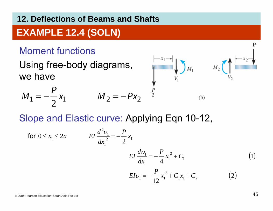
12. Deflections of Beams and ShaftsEXAMPLE 12.4 (SOLN)
Moment functionsUsing free-body diagramsUsing free-body diagrams, we have
P
Slope and Elastic curve: Applying Eqn 10-12
2211 2PxMxPM −=−=
Slope and Elastic curve: Applying Eqn 10-12,
220 12
1
12
1 xPdxdEIax −=≤≤υfor
( )
( )
14
3
12
11
1
P
CxPdxdEI +−=υ
©2005 Pearson Education South Asia Pte Ltd 45
( )212 211
311 CxCxPEI ++−=υ

12. Deflections of Beams and ShaftsEXAMPLE 12.4 (SOLN)
Slope and Elastic curve: Applying Eqn 10-12Applying Eqn 10-12,
0 222
2
2 PxdEIax −==≤≤υfor
( )332
22
222
2
CxPdEI
dx
+−=υ ( )
( )4
32
3
322
CxCxPEI
Cxdx
EI
++=
+=
υ ( )46 42322 CxCxEI ++−=υ
©2005 Pearson Education South Asia Pte Ltd 46
12. Deflections of Beams and ShaftsEXAMPLE 12.4 (SOLN)
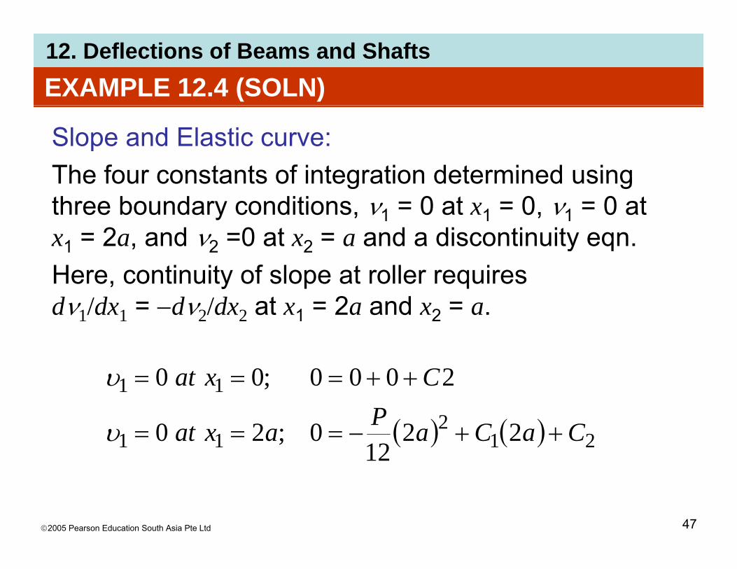
Slope and Elastic curve: The four constants of integration determined usingThe four constants of integration determined using three boundary conditions, ν1 = 0 at x1 = 0, ν1 = 0 at x1 = 2a, and ν2 =0 at x2 = a and a discontinuity eqn.1 , 2 2 y qHere, continuity of slope at roller requires dν1/dx1 = −dν2/dx2 at x1 = 2a and x2 = a.1 1 2 2 1 2
11 2000;00 Cxat ++===υ
( ) ( ) 212
11 2212
0;20 CaCaPaxat ++−===υ
©2005 Pearson Education South Asia Pte Ltd 47

12. Deflections of Beams and ShaftsEXAMPLE 12.4 (SOLN)
Slope and Elastic curve: ++300 CCPt
( ) ( ) ( ) ( ) ⎞⎜⎛ ++
++−===
2221
433
22
2;26
0;0
CaPCaPadad
CaCaaxat
υυ
υ
Solving we obtain
( ) ( ) ( ) ( )⎠
⎜⎝
+−−=+−−= 312
2
1
12
24
; CaCadxdx
Solving, we obtain
2 7Pa 342321 6
703
PaCPaCCPaC −====
©2005 Pearson Education South Asia Pte Ltd 48
12. Deflections of Beams and ShaftsEXAMPLE 12.4 (SOLN)
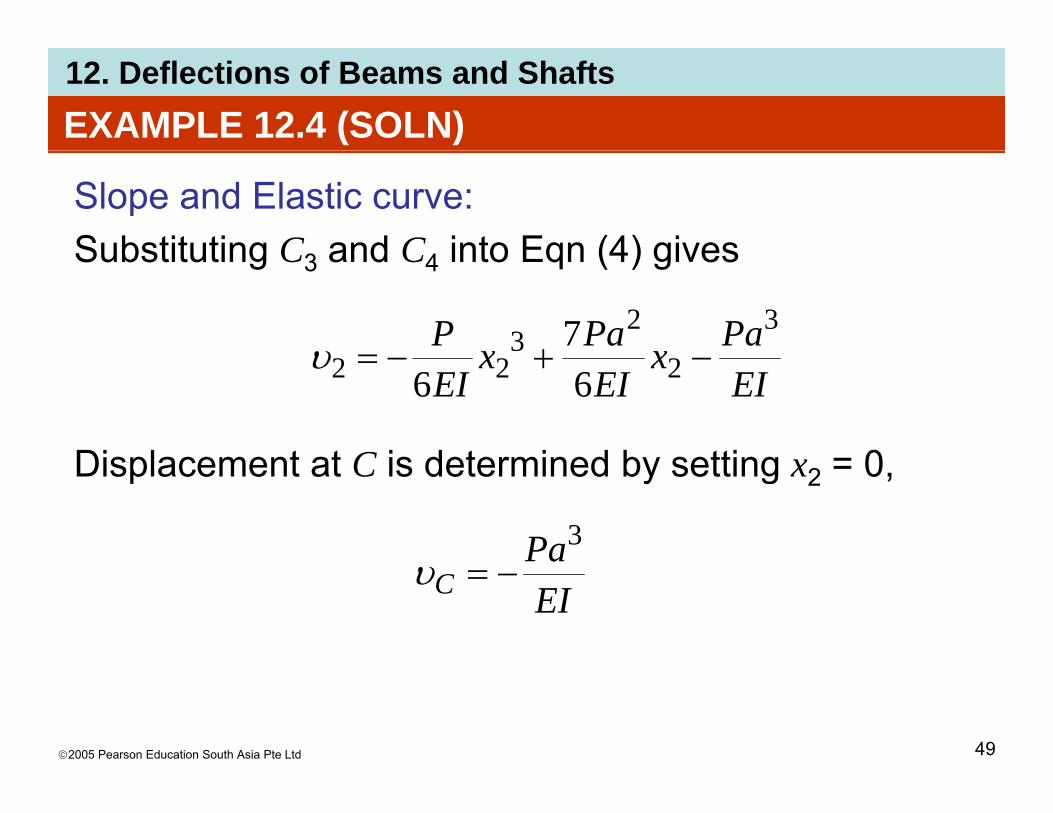
Slope and Elastic curve: Substituting C and C into Eqn (4) givesSubstituting C3 and C4 into Eqn (4) gives
PaxPaxP 323 7+=υ
Displacement at C is determined by setting = 0
EIx
EIx
EI 222 66−+−=υ
Displacement at C is determined by setting x2 = 0,
Pa3
EIPa
C −=υ
©2005 Pearson Education South Asia Pte Ltd 49

12. Deflections of Beams and ShaftsEXAMPLE 12.4 (SOLN)
• If several different loadings act on the beam the method of integration becomes more tedious to apply,method of integration becomes more tedious to apply, because separate loadings or moment functions must be written for each region of the beam.
8 t t f8 constants of integration
©2005 Pearson Education South Asia Pte Ltd 50
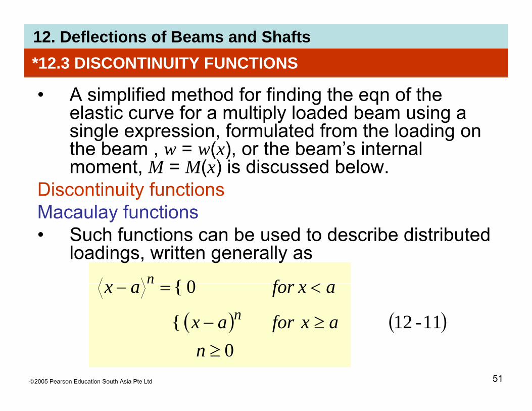
12. Deflections of Beams and Shafts*12.3 DISCONTINUITY FUNCTIONS
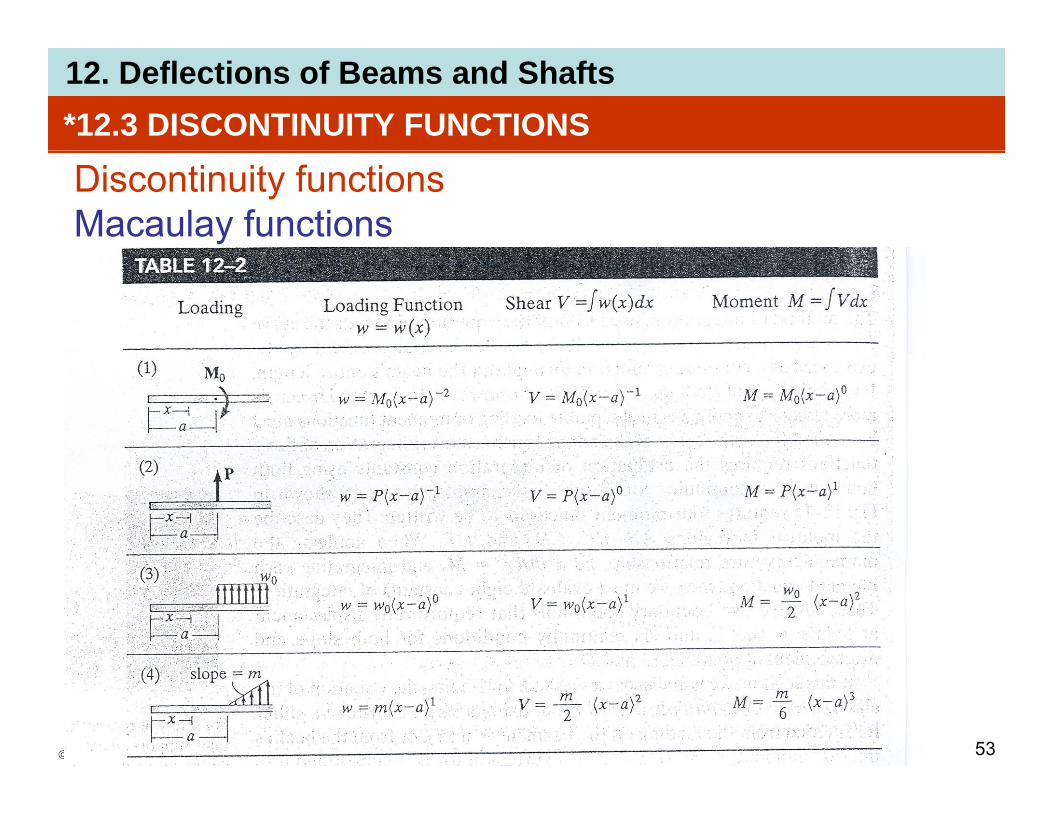
• A simplified method for finding the eqn of the elastic curve for a multiply loaded beam using a single expression formulated from the loading onsingle expression, formulated from the loading on the beam , w = w(x), or the beam’s internal moment, M = M(x) is discussed below.
Discontinuity functionsMacaulay functions
Such functions can be used to describe distributed• Such functions can be used to describe distributed loadings, written generally as
0{ <fn
( ) ( )11-12{
0{
≥−
<=−
axforax
axforaxn
n
©2005 Pearson Education South Asia Pte Ltd 51
0≥n
12. Deflections of Beams and Shafts*12.3 DISCONTINUITY FUNCTIONS
Discontinuity functionsMacaulay functions• x represents the coordinate position of a pt along
the beam• a is the location on the beam where aa is the location on the beam where a
“discontinuity” occurs, or the pt where a distributed loading begins.
• The functions describe both uniform load and triangular load.g
©2005 Pearson Education South Asia Pte Ltd 52
12. Deflections of Beams and Shafts*12.3 DISCONTINUITY FUNCTIONS
Discontinuity functionsMacaulay functions
©2005 Pearson Education South Asia Pte Ltd 53

12. Deflections of Beams and Shafts
©2005 Pearson Education South Asia Pte Ltd 54
12. Deflections of Beams and Shafts
©2005 Pearson Education South Asia Pte Ltd 55

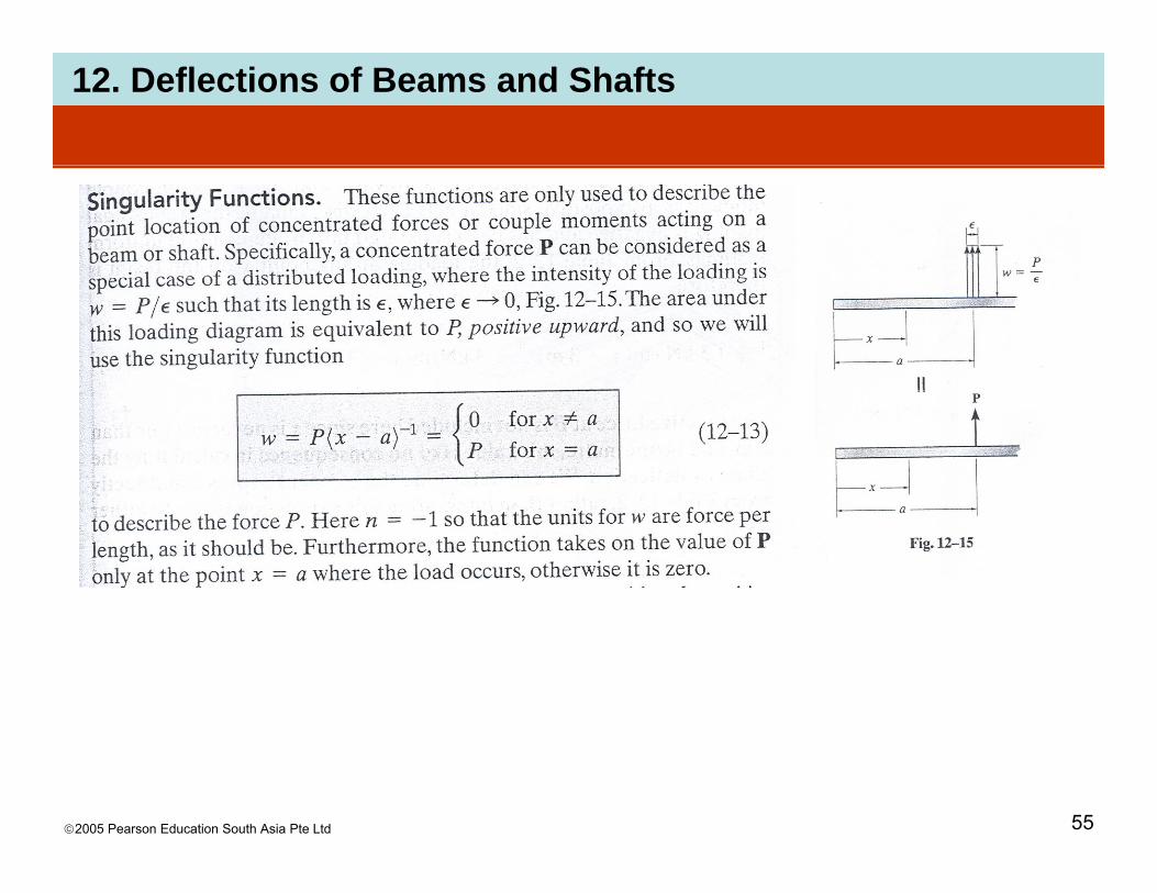
12. Deflections of Beams and ShaftsSingularity functions
©2005 Pearson Education South Asia Pte Ltd 56

12. Deflections of Beams and Shafts
©2005 Pearson Education South Asia Pte Ltd 57

12. Deflections of Beams and Shafts*12.3 DISCONTINUITY FUNCTIONS
Procedure for analysisElastic curve• Sketch the beam’s elastic curve and identify the
boundary conditions at the supports.• Zero displacement occurs at all pin and rollerZero displacement occurs at all pin and roller
supports, and zero slope and zero displacement occurs at fixed supports.Establish the a is so that it e tends to the right• Establish the x axis so that it extends to the right and has its origin at the beam’s left end.
Load or moment function• Calculate the support reactions and then use the
discontinuity functions in Table 12-2 to express either the loading w or the internal moment M as a
©2005 Pearson Education South Asia Pte Ltd 58
either the loading w or the internal moment M as a function of x.
12. Deflections of Beams and Shafts*12.3 DISCONTINUITY FUNCTIONS
Procedure for analysisLoad or moment function• Calculate the support reactions and then use the
discontinuity functions in Table 12-2 to express either the loading w or the internal moment M as a gfunction of x.
• Make sure to follow the sign convention for each loading as it applies for this equationloading as it applies for this equation.
• Note that the distributed loadings must extend all the way to the beam’s right end to be valid. If this d t th th d f itidoes not occur, use the method of superposition.
©2005 Pearson Education South Asia Pte Ltd 59

12. Deflections of Beams and Shafts*12.3 DISCONTINUITY FUNCTIONS
Procedure for analysisSlope and elastic curve
4 4• Substitute w into EI d4ν/dx4 = −w(x) or M into the moment curvature relation EI d2ν/dx2 = M, and integrate to obtain the eqns for the beam’s slope g q pand deflection.
• Evaluate the constants of integration using the boundary conditions and substitute theseboundary conditions, and substitute these constants into the slope and deflection eqns to obtain the final results.Wh th l d d fl ti l t d• When the slope and deflection eqns are evaluated at any pt on the beam, a +ve slope is counterclockwise, and a +ve displacement is
©2005 Pearson Education South Asia Pte Ltd 60
pupward.

12. Deflections of Beams and ShaftsEXAMPLE 12.5Determine the eqn of the elastic curve for the cantilevered beam shown. EI is constant.
©2005 Pearson Education South Asia Pte Ltd 61

12. Deflections of Beams and ShaftsEXAMPLE 12.5 (SOLN)Elastic curveThe loads cause the beam to deflect as shown. TheThe loads cause the beam to deflect as shown. The boundary conditions require zero slope and displacement at A.
©2005 Pearson Education South Asia Pte Ltd 62

12. Deflections of Beams and ShaftsEXAMPLE 12.5 (SOLN)Loading functionsSupport reactions shown on free-body diagram. SinceSupport reactions shown on free body diagram. Since distributed loading does not extend to C as required, use superposition of loadings to represent same effect.
©2005 Pearson Education South Asia Pte Ltd 63
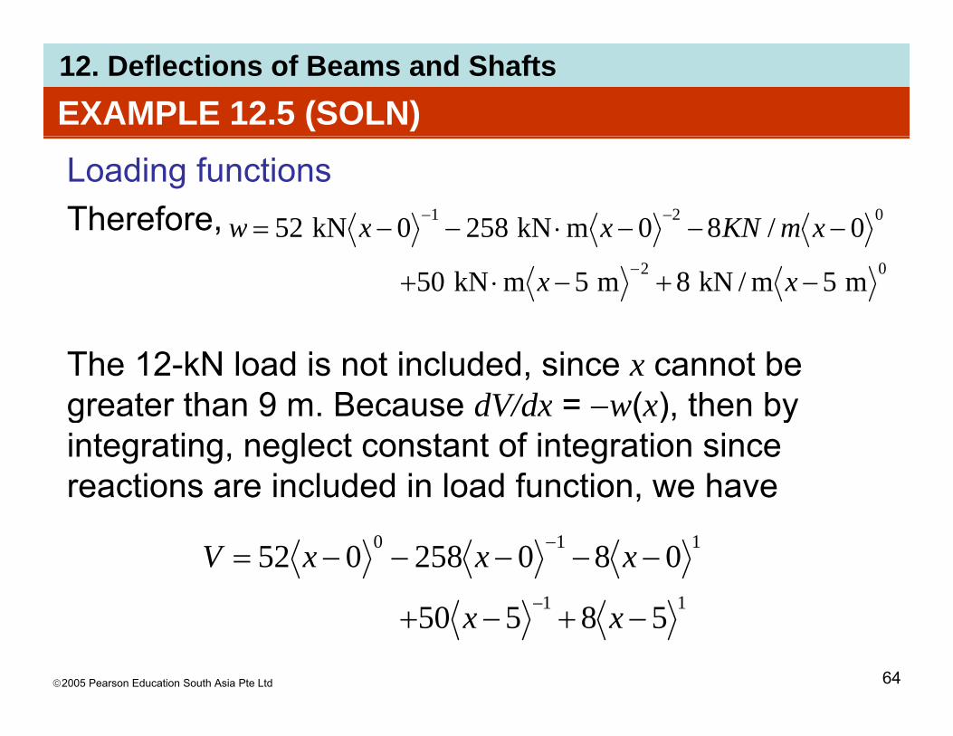
12. Deflections of Beams and ShaftsEXAMPLE 12.5 (SOLN)Loading functionsTherefore, 021 0/80mkN2580kN52 −−−⋅−−= −− xmKNxxwTherefore,
02 m5m/kN8m5mkN50
0/80mkN2580kN52
−+−⋅+
−−−⋅−−=− xx
xmKNxxw
The 12-kN load is not included, since x cannot be greater than 9 m. Because dV/dx = −w(x), then bygreater than 9 m. Because dV/dx w(x), then by integrating, neglect constant of integration since reactions are included in load function, we have
11
110 080258052 −−−−−= − xxxV
©2005 Pearson Education South Asia Pte Ltd 64
11 58550 −+−+ − xx

12. Deflections of Beams and ShaftsEXAMPLE 12.5 (SOLN)
Loading functionsFurthermore dM/dx = V so integrating again yieldsFurthermore, dM/dx = V, so integrating again yields
( ) ( ) 582155008
210520258 20210 −+−+−−−+−−= xxxxxM
( ) mkN5505445225822
022 ⋅−+−+−+−= xxxx
The same result can be obtained directly from Table 12 212-2.
©2005 Pearson Education South Asia Pte Ltd 65

12. Deflections of Beams and ShaftsEXAMPLE 12.5 (SOLN)Slope and elastic curveApplying Eqn 12-10 and integrating twice, we haveApplying Eqn 12 10 and integrating twice, we have
2022
54550452258 xxxxdEI +++=υ
312
2
54550426258
54550452258
3 CxxxxxdEI
xxxxdx
EI
++++
−+−+−+−=
υ
2432
1
525126129
53
5503
26258 3
xxxxEI
Cxxxxxdx
EI
++=
+−+−+−+−=
υ
21451
52533
129
CxCx
xxxxEI
++−+
−+−+−=υ
©2005 Pearson Education South Asia Pte Ltd 66
2153
CxCx +++
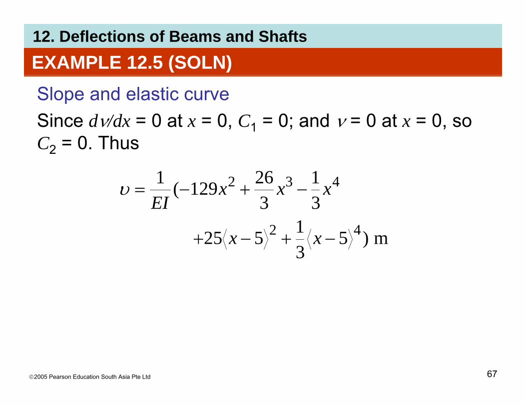
12. Deflections of Beams and ShaftsEXAMPLE 12.5 (SOLN)Slope and elastic curveSince dν/dx = 0 at x = 0, C1 = 0; and ν = 0 at x = 0, soSince dν/dx 0 at x 0, C1 0; and ν 0 at x 0, so C2 = 0. Thus
1261 432
131
326129(1
42
432 −+−= xxxEI
υ
m)531525 42 −+−+ xx
©2005 Pearson Education South Asia Pte Ltd 67

12. Deflections of Beams and Shafts
©2005 Pearson Education South Asia Pte Ltd 68

12. Deflections of Beams and Shafts
©2005 Pearson Education South Asia Pte Ltd 69

12. Deflections of Beams and Shafts
©2005 Pearson Education South Asia Pte Ltd 70

12. Deflections of Beams and Shafts
©2005 Pearson Education South Asia Pte Ltd 71