12 transformers and other equipment for switchgear installations
TRANSCRIPT

12
551
12 Transformers and other Equipment forSwitchgear Installations
12.1 Transformers
12.1.1 Design, types and dimensions
The purpose of transformers is to transfer electrical energy from systems of one voltageU1 to systems of another voltage U2.
Transformers can be differentiated according to their manner of operation (Fig. 12-1):
1. Power transformers, the windings of which are in parallel with the associatedsystems. The systems are electrically independent. The transfer of power is solelyby induction.
2. Autotransformers, the windings of which are connected in line (series winding RWand parallel winding PW). The throughput power SD is transferred partly byconduction and partly by induction.
3. Booster transformers; their windings are electrically independent, one winding beingconnected in series with one system in order to alter its voltage. The other windingis connected in parallel with its associated system (excitation winding EW). Theadditional power SZ is transferred purely inductively.
Fig. 12-1
Different types of transformers according to their manner of operation: a) Powertransformer, b) Autotransformer, RW Series winding, PW Parallel winding, c) Boostertransformer, EW Excitation winding, RW Series winding.
The following distinctions are made according to applications:
1. Transformers for the supply of power DIN EN 60076-1 (VDE 0532 Part 101), suchas distribution or main transformers, machine transformers and system-tietransformers,
2. Industrial transformers, such as welding transformers, furnace transformers,starting transformers and converter transformers,
3. Transformers for traction systems,
4. Special transformers, e.g. for testing, protection and control purposes.
Three-phase distribution transformers are covered by standards DIN 42500( HD 428.151) and DIN 42523 ( HD 538.151).

552
Transformers are divided into the following categories:
1. Class A: dry-type transformers (e.g. cast-resin transformers)Core and windings are not contained in an insulating liquid. Heat losses aredissipated direct to the ambient air, hence large surface area and low currentdensity. Up to approximately 20000 kVA and a maximum of 36 kV.ABB resin-encapsulated transformers of the RESIBLOC type are characterized byextremely high mechanical resistance of the windings because of fibre-glass-reinforced resin insulation and a very high resistance to fluctuations in temperature.
2. Class 0: oil-immersed transformersCore and windings are contained in mineral oil or similarly flammable synthetic liquidwith a fire point ≤ 300 °C which is simultaneously a coolant and insulating medium.
3. Class KCore and windings are contained in a synthetic liquid having a fire point > 300 °Cwhich is also a coolant and insulating medium. In construction, they are much likeoil-immersed transformers.
ABB uses silicone liquid for transformers with ratings of up to 10 000 kVA andservice voltages of up to 36 kV.Silicone liquid is flame-retardant and non-polluting. Other synthetic liquids (ester)with a fire point > 300 °C may be encountered, besides silicone liquid.
Askarel is no longer used as a coolant (environmental hazard).
Ratio variability
Ability to vary the ratio is important particularly with main transformers; it is used formatching the service voltage in the event of load fluctuations, for load distribution or foradjusting active and reactive current in interconnected networks, and for voltagecorrection with electric furnaces, rectifier stations, etc. In the simplest case, this is donewith the transformer dead, by altering the connection between winding sections with theaid of extra winding terminals, so-called tappings (normally + 4 % or + 5 %).
For stepwise variation under load, the tap changer (available in oil-insulated and drydesign) is preferably installed at the neutral end of the HV winding with powertransformers, and at the series winding with series transformers and autotransformers.
The tap changer, which connects the respective tappings while under load, consistsbasically of a load switch and a selector (or alternatively just a selector switch) with orwithout preselection.
The number of tappings and range of adjustment for power transformers of up to 40MVA and 110 kV are standardized (DIN 42515).
Continuous variation under load can be done with moving windings in the form of aspecial design as a rotary transformer or moving-coil regulator.

12
553
Fig. 12-2 shows an oil-insulated transformer (a) which has the currently preferredhermetically encapsulated design without expansion tank and a resin-encapsulatedtransformer (b) without enclosure. There are no standards for the dimensions ofdistribution transformers. Table 12-1 lists the main dimensions of a number ofdistribution transformers as examples of practical transformer designs with varyingtechnical data from the ABB production range.
Fig. 12-2
Structural types of distributiontransformers
a) hermetically encapsulated oil-insulated transformers
b) RESIBLOC resin-encapsulatedtransformers without enclosure
Table 12-1
Main dimensions of ABB distribution transformers, as shown in Fig. 12-2a) Oil-insulated transformers, hermetically encapsulated b) RESIBLOC resin-encapsulated transformers without enclosure
Tech. data Main dimensions in mma b c d
a) 10 kV, 250 kVA, 4% 1170 740 1440 520 20 kV, 250 kVA, 4% 1170 770 1510 520 10 kV, 630 kVA, 6% 1420 870 1440 670 20 kV, 630 kVA, 6% 1460 930 1525 670
b) 10 kV, 250 kVA, 4% 1110 660 1250 520 20 kV, 250 kVA, 4% 1350 660 1560 520 10 kV, 630 kVA, 6% 1500 810 1360 670 20 kV, 630 kVA, 6% 1560 810 1820 670
a)
b)
bda
d
c
ad
c
bd

554
12.1.2 Vector groups and connections
Vector groups
The vector group denotes the way in which the windings are connected and the phaseposition of their respective voltage vectors. It consists of letters identifying theconfiguration of the phase windings and a number indicating the phase angle betweenthe voltages of the windings.
With three-phase a.c. the winding connections are categorized as follows:
a) Delta (D, d)b) Star (Y, y)c) Interconnected star (Z, z)d) Open (III, iii)
Capital letters relate to the high-voltage windings, lower-case letters to the medium andlow-voltage windings. The vector group begins with the capital letter. In the case ofmore than one winding with the same rated voltage, the capital letter is assigned to thewinding with the highest rated power; if the power ratings are the same, to the windingwhich comes first in the order of connections listed above. If the neutral of a winding instar or interconnected star is brought out, the letter symbols are YN or ZN, or yn or zn,respectively.
To identify the phase angle, the vector of the high-voltage winding is taken as areference. The number, multiplied by 30° denotes the angle by which the vector of theLV winding lags that of the HV winding. With multi-winding transformers, the vector ofthe HV winding remains the reference; the symbol for this winding comes first, the othersymbols follow in descending order according to the winding’s rated voltages.
Example:
For a transformer with three power windings (HV windings 220 kV in neutral connectionwith brought-out neutral, MV winding 110 kV in neutral connection with brought-outneutral, and LV winding 10 kV in delta connection), if the vectors of the neutral voltageof HV and MV winding are in phase and the vector of the neutral voltage of theLVwinding lags behind them by 5 · 30 = 150°, the identifying symbols are:
YN, yn 0, d 5.
Preferred connections
Yyn 0 for distribution transformers. The neutral point can be loaded continuouslywith up to 10 % of the rated current, or with up to 25 % of the rated current fora maximum of 1.5 hours. Example: for connecting arc suppression coils.
YNyn 0 with compensating winding, used for large system-tie transformers. Theneutral point can be loaded continuously with the rated current.
YNd 5 intended for machine and main transformers in large power stations andtransformer stations. The neutral point can be loaded with the rated current.Arc suppression coils can be connected (delta winding dimensioned for themachine voltage).
Yzn 5 for distribution transformers, used up to approx. 250 kVA for local distributionsystems. The neutral point can be loaded with the rated current.
12
555
Dyn 5 for distribution transformers above approx. 315 kVA, for local and industrialdistribution systems. The neutral point can be loaded with the rated current.
Ii 0 for single-phase transformers, intended for traction power supply or forthree-phase banks with very high voltages and powers.
If single-phase transformers are combined to form three-phase banks, the switchgear,instrument transformers and conductor cross-sections must be designed for the voltageand current ratings given in Table 12-2.
Identification and arrangement of terminals
Terminations of the windings (coils) brought out in the same winding sense are denoted1U1,1V1,1W1 for the primary windings and 2U1, 2V1, 2W1 for the secondary windings.The terminations at the other ends of the windings, brought out in the inverse windingsense, are designated 1U2, 1V2, 1W2 for the primary windings and 2U2, 2V2, 2W2 forthe secondary windings.
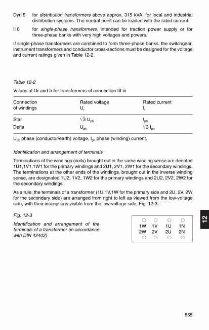
As a rule, the terminals of a transformer (1U,1V,1W for the primary side and 2U, 2V, 2Wfor the secondary side) are arranged from right to left as viewed from the low-voltageside, with their inscriptions visible from the low-voltage side, Fig. 12-3.
Fig. 12-3
Identification and arrangement of theterminals of a transformer (in accordancewith DIN 42402)
1W 1V 1U 1N2W 2V 2U 2N
Table 12-2
Values of Ur and Ir for transformers of connection III iii
Connection Rated voltage Rated currentof windings Ur Ir
Star 3 Uph Iph
Delta Uph 3 Iph
Uph phase (conductor/earth) voltage, Iph phase (winding) current.

556
12.1.3 Impedance voltage, voltage variation and short-circuit current withstand
Voltage drops
The impedance voltage Ukr is defined as that voltage having the rated frequency whichmust be applied to the primary side of a transformer so that the rated current Ir flowswhen the secondary terminals are short-circuited. Since only the short-circuitimpedance is present in the circuit,
Ukr = 3 · Ir · Zk.
The rated impedance voltage is usually stated as a percentage of the voltage rating Ur
of the winding to which the voltage is applied:
Ukrukr = — · 100 %.Ur
The impedance voltage is composed of the ohmic voltage drop (UR, uR) which is inphase with the current, and the reactive voltage (Ux, ux), which leads the current in timeby 90°.
Ohmic voltage drop:
Pkr Impedance losses at rated poweruRr = — · 100 % = ——————————————— 100 %.
Sr rated power
Reactive voltage:
uXr = ukr2 – uRr
2 .
In the case of a partial load, the short-circuit voltage Uk is proportional to the load on thetransformer:
I Suk = ukr – = ukr –
I r Sr
For distribution transformers, according to DIN 42500 a rated impedance voltage ukr isallocated to each power rating Sr, Table 12-3.
Table 12-3
Rated impedance voltage ukr
Rated output Sr in kVA1) ukr
50 (63) 100 160 (200) 250 (315) 400 (500) 630 4 %630 (800) 1000 (1250) 1600 (2000) 2500 6 %
1) Rated outputs not in brackets are preferred.

12
557
Transformers with a rated impedance voltage u kr = 4 % are used mainly in distributionnetworks in order to keep the voltage drop small.
Transformers with a rated impedance voltage u kr = 6 % are preferably to be used inindustrial networks and in high-power distribution networks in order to limit the short-circuit stress. The rated impedance voltages of medium-size and large transformers areeven higher so as to achieve sufficient short-circuit strength.
Voltage variation
The voltage variation between no-load and a symmetrical load of any magnitude for anycos ϕ can be calculated from the rated impedance voltage and the impedance lossesat rated load. It is denoted uϕ, and referred to the rated voltage.For a given part load a = S/Sr and a given power factor cos ϕ,
1 (a · uϕ )2 1 (a · u ϕ)4
uϕ = a · uϕ + – · ———— + – · ———— + …1)
2 102 8 106
whereuϕ = uRr · cos ϕ + uXr · sin ϕ
anduϕ = uRr · sin ϕ – uXr · cos ϕ
The actual voltage at the terminals on the output side of the loaded transformer willthen be
uϕUa = Ur (1 – ——— )100 %
Example:
Find the full-load voltage Ua for a transformer with rated load on the output side atcos ϕ = 0.8 (sin ϕ = 0.6).
Rated output: Sr = 2500 kVA, Impedance losses: Pkr = 24 kW,Impedance voltage: ukr = 6 %.
Pkr 24 kWuRr = — · 100 % = ——–—— 100 % = 0.96 %
Sr 2500 kVA
uxr = ukr2 – uRr
2 = 62 – 0.962% = 5.923 %
uϕ = uRr cos ϕ + uxr sin ϕ = 0.96 · 0.8 + 5.923 · 0.6 = 4.32 % uϕ = uRr sin ϕ – uxr cos ϕ = 0.96 · 0.6 – 5.923 · 0.8 = – 4.16 %
1 (uϕ )2 1 (– 4.16)2
uϕ = uϕ + — —— = 4.32 + — · ————— = 4.4 %.2 102 2 102
uϕUa = Ur (1 – ———— ) = 0.965 · Ur.100 %
1) If ukr < 20 % the third summand can be disregarded. The second summand may also bedisregarded if ukr < 4 %.

558
Short-circuit current and its limitation
The criterion for the short-circuit is a reference impedance composed of theimpedances of the network (ZQ) and transformer (Zk). This is
Ur IkIk3p = —————–— ≈ ——— · 100 %.3 |ZQ + Zk | ukr %
With distribution transformers of ratings up to 3150 kVA and ZQ ≤ 0.05 · Zk, the networkimpedance ZQ can usually be disregarded.
The short-circuit impedance limits the short-circuit current. Thermal stress is governedby the sustained short-circuit current Ik. The maximum permissible short-circuit durationis 2 s as per DIN 57532-5 (VDE 0532 Part 5), unless otherwise specified by thecustomer.
With transformers of vector groups Dy and Yd, the single-phase sustained short-circuitcurrent is about the same as the three-phase value. At windings in interconnected starconnection, the single-phase sustained short-circuit current can reach roughly 1.4times the three-phase value, as its zero-sequence impedance is usually very small.
Table 12-4
Reference impedances for two-winding transformers (to VDE 0532 Part 5)
Rated power Typical Maximum Typical values ofvalues system voltage reference systemof zk fault level SkQ
1)
(or ukr)kVA % kV MVA
7.2 12 17.5
to 630 4.0 and 24 500
from 630 to 1 250 5.0 136 1 000
from 1 250 to 3 150 6.25 152 and 172.5 3 000
from 3 150 to 6 300 7.15 100 and 123 6 000
from 6 300 to 12 500 8.35 145 and 170 10 000
from 12 500 to 25 000 10.0 245 20 000
from 25 000 to 200 000 12.5 300 30 000
420 40 000
1) If not specified

12
559
Fig. 12-4
Typical values for two-winding transformers. i0 (percentage no-load current), p0
(percentage no-load losses) and pk (percentage impedance losses) as a function ofrated power Sr.
Power range 2.5 MVA to DIN 42500
Power range 2 to 10 MVA to DIN 42504 and 12.5 to 80 MVA to DIN 42508 Upper limit of pk for rated high voltage 123 kV,Lower limit of pk for rated high voltage 36 kV.
12.1.4 Losses, cooling and overload capacity
Transformer losses
Fig. 12-4 shows the usual values of no-load losses P0 and impedance loss Pk for two-winding transformers. The total losses Pv of a transformer at any loading a = S/Sr canbe calculated from the relationship:
Pv = P0 + a2 Pk.
The no-load losses P0 are composed of the hysteresis losses and eddy-current lossesin the iron, and leakage losses in the dielectric. These losses are not affected by theload.

560
The impedance losses Pk comprise the copper losses in the windings and the additionallosses. Impedance losses, which are caused by eddy currents inside and outside thewindings, vary as the square of the load. The efficiency η of a transformer at any loadis determined sufficiently accurately from
P0 + a2 Pkη = 100 % – —————————— · 100 % a · Sr · cos ϕ + P0
Example
Find the efficiency of a 250 kVA transformer for 20/0.4 kV with P0 = 610 W and Pk = 4450 W at half-load (a = 0.5) and cos ϕ = 0.8.
0.61 + 0.52 · 4 45η = 100 % – ———————————— · 100 % = 98.29 %.
0.5 · 250 · 0.8 + 0.61
In order to assess a transformer, however, it is more informative to evaluate the lossesand their distribution, rather than the efficiency.
Cooling
The method of cooling is stated by the manufacturer in the form of four capital letters,the first two letters denoting the coolant and the manner of circulation for the winding,and the last two letters indicating the coolant and manner of circulation for cooling theoutside of the transformer. These code letters are explained in Table 12-5.
Table 12-5
Key to cooling systems
Coolant Symbols
Mineral oil or equiv. synth.liquid with fire point ≤ 300 °c OOther synth. Iiquids KGas with fire point > 300 °C GAir (dry-type transformers) AWater W
Coolant circulation Symbols
Natural circulation NForced circulation (non-directed) FForced circulation (directed) D
Examples
AN = Dry-type transformer with natural air circulation, ONAN = Oil-immersed self-cooled transformer.

12
561
Overload capacity to DIN 57536 (VDE 0536)
The maximum time for which transformers can be overloaded at a given bias load andcoolant temperature is shown in Fig. 12-5 for air-cooled oil-immersed transformers inthe case of two different loads recurring regularly in a 24-hour cycle.
In the diagram:
K1 Initial load as a proportion of rated power,K2 Permitted overload as a proportion of rated power (normally > 1),t Duration of K2 in h,Θa Coolant temperature in °C.
Hence
S1 S2 K2 S2K1 = —; K2 = —; — = —Sr Sr K1 S1
Here, S1 is the initial load, S2 the maximum permitted load and Sr the rated power.Under normal circumstances, K2 should not exceed 1.5.
Example:
Transformer 1250 kVA with ONAN cooling. Bias load 750 kVA. What is the maximumpermitted load over 4 hours at 20 °C?
K1 = 0.6; t = 4 h. Fig. 12-5a yields K2 = 1.29.
S2 = K2 · Sr = 1.29 · 1250 kVA = 1612 kVA.
Fig. 12-5
Transformer with ONAN and ONAF cooling. Values of K2 for given values of K1 and t(in hours), a) Θa = 20 °C, b) Θa = 30 °C
a) b)
K1 K1
K2K2
K2
K1= 1,8

562
For a given case of transformer loading, the power rating Sr can be calculated from:
S1 S2Sr = — = —K1 K2
Example:
At Θa = 30 °C, a transformer with ONAN cooling is to run for 4 hours at 450 kVA andotherwise at 250 kVA. What power rating is required?
S1 = 250 kVA, t1 = 20 h; S2 = 450 kVA, t2 = 4 h.
S2 450 K2— = ––– = 1.8 = —S1 250 K1
From Fig. 12-5 b for K2/K1 = 1.8 when t = 4 h: K1 = 0.65; K2 = 1.17.
450 250Sr = ––– = ––– = 385 kVA → 400 kVA.
1.17 0.65
12.1.5 Parallel operation
Transformers are in parallel operation if they are connected in parallel on at least twosides. A distinction is made between busbar interconnection and networkinterconnection. The following conditions must be satisfied in order to avoid dangeroustransient currents:
1. vector groups should have the same phase angle number; terminals of the samedesignation must be connected together on the HV and LV sides; Exception: Phaseangle numbers 5 and 11 (Table 12-6);
2. the ratios should be as similar as possible, i.e. the same rated voltages on the HVand LV sides;
3. approximately the same impedance voltages uk maximum permissible discrepancies± 10 %. In the event of larger differences, an inductance (reactor) can be connectedahead of the transformer with the lower impedance voltage.
4. rated output ratio smaller than 3:1.
Table 12-6 Parallel operation of transformers with phase angle numbers 5 and 11
Phase angle Phase angle Connection to conductors Connection to conductorsnumber number HV side LV siderequired available L1 L2 L3 L1 L2 L3
5 5 1U 1V 1W 2U2 2V2 2W2
5 11 1U 1W 1V 2W1 2V1 2U1or 1W 1V 1U 2V1 2U1 2W1or 1V 1U 1W 2U1 2W1 2V1
11 11 1U 1V 1W 2U1 2V1 2W1
11 5 1U 1W 1V 2W2 2V2 2U2or 1W 1V 1U 2V2 2U2 2W2or 1V 1U 1W 2U2 2W2 2V2

12
563
Load distribution of parallel transformers with different rated impedance voltages
Transformers connected in parallel assume a partial load such that all the transformershave the same average impedance voltage. If the impedance voltage of a transformeris referred to an output other than its rated output, its magnitude varies in accordancewith the output. A 100 kVA transformer with ukr = 4 % has at 60 kVA an impedancevoltage uk of 0.6 · 4 = 2.4%.
Example:
transformer 1: Sr1 = 100 kVA, ukr1 = 4.0 %transformer 2: Sr2 = 250 kVA, ukr2 = 6.0 %transformer 3: Sr3 = 500 kVA, ukr3 = 4.5 %
total S = 850 kVA
We have:
S Sr1 Sr2— = —— + —— + …uk uk1 uk2
The resultant impedance voltage is then:
S 850uk = —————–—————— = —————–—————— = 4.78 %
Sr1 Sr2 Sr3 100 250 500—— + —— + —— —— + —— + ——ukr1 ukr2 ukr3 4 6 4.5
The power assumed by the individual transformers is:
uk 4.78S1 = Sr1 —— = 100 · —–— = 120 kVA
ukr1 4
uk 4.78S2 = Sr2 —— = 250 · —–— = 199 kVA
ukr2 6
uk 4.78S3 = Sr3 —— = 500 · —–— = 531 kVA
ukr3 4.5
Stot = S1 + S2 + S3 = 120 kVA
Transformer 1 is thus overloaded by 20 % and transformer 3 by 6 %. Since theindividual transformers should not be subjected to overload, the transformers may onlyassume a partial load such that the impedance voltage of each is uk = 4 %, as in thecase with transformer 1. Therefore,
4S1 = 100 · – = 100 kVA
4

564
4S2 = 250 · – = 167 kVA
6
4S3 = 500 · –— = 444 kVA
4.5
Stot = S1 + S2 +S3 = 711 kVA
If this output is not sufficient, another 160 kVA transformer with ukr = 4 % will have to beinstalled.
Effect of dissimilar transformation ratios of transformers connected in parallel
Dangerous transient currents can occur if transformers with different voltages betweentaps are operated in parallel. Disregarding any dissimilarity in impedance phase angleϕk, the voltage difference ∆ u proportional to the difference in ratio drives through bothsides a circulating current of
∆ uIa = ————————
uk1/Ir1 + uk2/Ir2
If, for example, uk1 = uk2 = 6 %, Ir1 = 910 A, Ir2 = 1445 A und ∆ u = 4 %, then
4 %Ia = ——————————————— = 377.34 A.
6 % / 910 A + 6 % / 1445 A
This balancing current is superimposed on the transformer load currents that aresupplied to the network. It is added to the current of that transformer which has thegreater secondary no-load voltage.
12.1.6 Protective devices for transformers
Overcurrent time relays respond to short circuits; they trip the circuit-breakers.
Thermal relays respond to unacceptable temperature rises in the transformer, andsignal overloads.
Make-proof percentage differential relays detect internal short circuits and faults,including those on lines between the current transformers; they trip the appropriatetransformer breakers, but do not respond to the inrush current of a sound transformer.
Buchholz relays detect internal damage due to gassing or oil flow; they signal minordisturbances and trip the breaker if the trouble is serious.
Temperature monitors signal when a set temperature is reached, or trip circuit-breakers.
Dial-type telethermometers indicate the temperature in the transformer’s topmost oillayer with maximum and minimum signal contacts.
Oil level alarms respond if the oil level is too low.
Oil flow indicators detect any disruption in the circulation in closed-circuit cooling andtrigger an alarm.
Airflow indicators detect any break in the flow of forced-circulation air, and trigger analarm.
12
565
12.1.7 Noise levels and means of noise abatement
Since transformers are located in or near residential areas, the noise they producemust be determined so as to assess the need for any countermeasures.
The noise of transformers is defined as the A-weighted sound pressure level measuredin dB (A) at a specified measuring surface with a sound level meter, and then convertedto a sound power level with the following formula:
LWA = LPA + LS
In which:
LWA A-weighted sound power level in dBLPA A-weighted sound pressure level in dBLS Measuring-surface level in dB
The measurements must be performed according to DIN EN 60551 (VDE 0532 Part 7).For transformers with water cooling or fan-less air cooling, at least 6 measurementsmust be taken at a distance of 0.3 m from the surface of the transformer. Fortransformers with other cooling systems, the relevant measurement regulations as perDIN EN 60551 (VDE 0532 Part 7) apply.
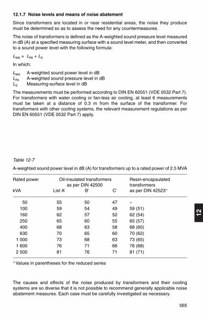
Table 12-7
A-weighted sound power level in dB (A) for transformers up to a rated power of 2.5 MVA
Rated power Oil-insulated transformers Resin-encapsulatedas per DIN 42500 transformers
kVA List A’ B’ C’ as per DIN 425231)
50 55 50 47 –100 59 54 49 59 (51)160 62 57 52 62 (54)250 65 60 55 65 (57)400 68 63 58 68 (60)630 70 65 60 70 (62)
1 000 73 68 63 73 (65)1 600 76 71 66 76 (68)2 500 81 76 71 81 (71)
1) Values in parentheses for the reduced series
The causes and effects of the noise produced by transformers and their coolingsystems are so diverse that it is not possible to recommend generally applicable noiseabatement measures. Each case must be carefully investigated as necessary.

566
Possible measures include:
Actions by the transformer manufacturer to reduce airborne and structure-borne noise.
Structural measures against airborne noise, e.g. sound-absorbent walls or enclosures.
Anti-vibration treatment of the foundations to reduce transmission of structure-bornenoise, e.g. spring-mounted supporting structure.
12.2 Current-limiting reactors EN 60289 (VDE 0532 Part 20)
12.2.1 Dimensioning
Current-limiting reactors (series reactors) to DIN VDE 0532, Part 2 are reactancesemployed to limit short-circuit currents. They are used when one wishes to reduce theshort-circuit power of networks or installations to a value which is acceptable withregard to the short-circuit strength of the equipment or the breaking capacity of thecircuit-breaker.
Since the reactance of a series reactor must remain constant when short-circuitcurrents occur, only the air-core type of construction is suitable1). If iron cores wereused, saturation of the iron brought about by the short-circuit currents would cause adrop in the inductance of the coil, thus seriously reducing the protection against shortcircuits.
Voltage drop and voltage variation
The rated impedance is the impedance per phase at rated frequency. The resistanceof a current-limiting reactor is negligible and in general, amounts to not more than some3 % of the reactance XL.
The rated voltage drop ∆ Ur is the voltage induced in the reactor when operating withrated current and rated reactance:
∆ Ur = Ir · XL
When referred to the nominal voltage of the system, the rated voltage drop is denoted∆ ur and usually stated in %:
∆ Ur · 3∆ ur = ————— 100 %.
Un
Example:
A reactor in a three-phase system with a rated voltage of 10 kV has a reactance of 5 %.Its rated current is 400 A. This statement indicates that the voltage drop at the reactoris 5 % of the system phase-to-earth voltage. The absolute value in volts is
∆ Ur · Un 5 % · 10 000 V∆ Ur = —————— = ————————— = 289 V.
3 · 100 % 3 · 100 %
1) Air-core reactors can cause the frequency of the recovery voltage to assume extremely high values(150 to 250 kHz). Reduction of these natural frequencies to the values for circuit-breakers definedby VDE 0670 Part 104 can be achieved by fitting capacitors.

12
567
According to Fig. 12-6, for a given load a= I/Ir and a given power factor cos ϕ
Uϕ = a · ∆ Ur · cos (90 ° – ϕ)
or uϕ = a · ∆ ur · sin ϕ.
Example:
At a power factor of cos ϕ = 0.8 and rated current, a reactor with ∆ ur = 6 % causes avoltage variation in the network of uϕ = 6 % • 0.6 = 3.6 %.
If large motors are connected after reactors and the current ratings of the motor and thereactor are of the same order of magnitude, account must be taken of the voltage dropdue to the large starting current of the motor. The drop must not be so large as toendanger the safe run-up of the motor.
Inherent power and throughput power
The inherent power of a reactor is the product of the voltage drop ∆ Ur and the ratedcurrent Ir.
SE = 3 · ∆ Ur · Ir (three-phase).
The throughput of a reactor is the product of the line-to-earth voltage Un/3 and therated current Ir.
SD = 3 · Un · Ir (three-phase).
Selection of a current-limiting reactor
If the given short-circuit power Sk1 of a grid system is to be reduced to a value of Sk" byfitting a reactor, its required percentage rated voltage drop is
Sk1 – Sk2∆ ur = 1.1 · 100 % · SD · ————— .Sk1 · Sk2
For given values of reactance and current, the voltage variation Uϕ in the network, i.e.the difference between the network voltage before and after the reactor, is alsodependent on cos ϕ, Fig. 12-6. Thus, whereas the voltage difference Uϕ across thereactor is small under normal operating conditions, it increases in the event of a shortcircuit
1. in proportion to the short-circuit current and
2. with the increase in phase displacement angle under fault conditions.
Fig. 12-6
Vector diagram of a reactor:
a) Normal operationb) Short-circuit operationU1 System voltage before reactorU2 System voltage after reactorUϕ Voltage variation in system

568
Example:
Un = 6 kV, lr = 600 A;Sk1 = 600 MVA, Sk2 = 100 MVA;
600 MVA – 100 MVA∆ ur = 1.1 · 100 % · 3 · 6 kV · 0.6 kA ———————————— = 5.72 %.600 MVA · 100 MVA
In practice, one will select the next-highest standardized value, 6 % in this instance.
If the short-circuit power Sk1 before a reactor is given, and its percentage rated voltagedrop is ∆ ur, the short-circuit power Sk2 after the reactor is:
1.1 · 100 % · SD · Sk1Sk2 = ———————————————.1.1 · 100 % · SD + ∆ ur · Sk1
Taking the values of the example above, this yields:
1.1 · 100 % · 3 · 6 kV · 0.6 kA · 600 MVASk2 = ———————————————————————————— = 96 MVA.
1.1 · 100 % · 3 · 6 kV · 0.6 kA + 6 % · 600 MVA
Fig. 12-7
The most common reactor connections: a) Feeder connection, b) Tee-off connection, c) Busbar sectionalizer connection.
In power stations with a high short-circuit power, it is usual to fit busbar sectionalizingreactors together with bypass circuit-breakers, as shown in c). In this way, a permanentconnection is established between the busbars, although in the event of a fault, whenthe circuit-breaker opens, the short-circuit power is limited approximately to that of theindividual systems.
It is even better to use Is-limiters (Section 8.1.6) instead of circuit-breakers forbypassing reactors, because these devices interrupt the bypass without any delay andtherefore prevent hazardous peak current values from occurring.
12.2.2 Reactor connection
The scheme shown in Fig. 12-7 under a), with the reactors in the tee-offs, is the onemost commonly used. The circuit shown in b), with the reactors in the feeder, is oftenchosen for reasons of saving space. For the same degree of protection, the costs ofpurchase and operation are higher than with reactors in the branches.

12
569
12.2.3 Installation of reactors
When installing reactors, care must be taken to ensure that the heat losses occurringduring operation are dissipated by adequate ventilation. As a rough estimate, one canassume a fresh air requirement of 4 to 5 m3/min per kilowatt of heat loss. The air flowcross-sections necessary in the rooms can be calculated more accurately using themethod described in Section 4.4.2 for transformers.
Care must also be taken that reactors are situated sufficiently far away fromneighbouring metal parts to ensure that these are not heated excessively by eddycurrents.
Reactors should not be situated at distances of less than 500 mm from constructionalitems of steel, and steel reinforcement in ceilings, floors and walls. If the floor issteel-reinforced, the reactor must be placed on a concrete pedestal, Fig. 12-8.
Fig. 12-8
Installation of a current-limiting reactor:Dm mean diameter of reactor, a distancebetween centre line of reactor and metalitem1 Steel-reinforced wall2 Reinforcing bars(dimensions in mm)
With cell enclosures of non-magnetic materials (aluminium alloys), the minimumclearance for the highest equipment voltage in question (DIN VDE 0101) is sufficient.Closed structures (short-circuit loops) with a good electrical conductivity must beavoided in the vicinity of strong magnetic fields. If necessary, the short-circuit loopshould be split and the junction joined by means of non-conducting material to preventexcessive heating by circulating currents.
If one is forced to use magnetic materials, the distance between reactor and metalstructure should be selected so that under rated conditions, the root-mean-squarevalue of the magnetic field strength does not exceed 20 A/cm. The field strength iscalculated as
Ir · w · DmH = 0.1 · ————–— a2
Here, Ir rated current in A, w number of turns in reactor, for Dm and a, see Fig. 12-8.

570
12.3 Capacitors
12.3.1 Power capacitors
The term power capacitor is chiefly applied to capacitors having a rated frequency of 50 or 60 Hz which compensate the reactive power at points of heavy demand in publicand industrial networks. This general designation also includes “furnace capacitors”and “medium-frequency capacitors”, which cover the high reactive power requirementof melting furnaces and inductive heating coils, and also “welding machine capacitors”and “fluorescent lamp capacitors” used for compensating welding transformers and theballasts of fluorescent lamps. The design of power capacitors is regulated by thefollowing standards: DIN VDE 0560-1 (VDE 0560 Part 1), and DIN EN 60831-1 (VDE0560 Part 46) – self-restoring up to 1000 V –, DIN EN 60931-3 (VDE 0560 Part 45) –non-self-restoring up to 1000 V – and DIN EN 60871-1 (VDE 0560 Part 410) – over1000 V –.
The reactive power of a capacitor is determined by its capacitance, the rms value of theoperating voltage and the system frequency:
Qc = U 2 · ω · C.
The rated power of a capacitor as stated on its nameplate is always in relation to itsrated voltage Ur and rated frequency fr.
In three-phase networks, the capacitors, always three of the same size, are connectedin either star or delta. If
C1 is the capacitance in one phase with star connection, and
C12 is the capacitance in one phase with delta connection,
then for the same reactive power:
C1 = 3 C12.
The temperature range for power capacitors is specified by the temperature classes(DIN EN 60831-1, Table 1). The following temperature values are applicable for thepermissible ambient temperatures, e.g. for the -25°C class (preferred temperatureclass),
maximum: 50 °C,max. average over 24 h: 40 °C,max. average over 1 year: 30 °C,minimum: -25 °C.
Voltage and frequency increases and total harmonic distortion of the voltage or thecurrent place additional stress on capacitors.
Capacitors must be able to carry continuously 1.3 times the current flowing withsinusoidal rated voltage and frequency at an ambient air temperature corresponding toits temperature class. With this loading, the voltage must not be higher than 1.1 Ur, noaccount being taken of transient overvoltages.
If the limiting conditions stated above are exceeded, the chosen capacitor must bereplaced by one with a higher voltage rating and a rated power according to theequation
Qr2 = Qr1 (Ur2/Ur1)2.
12
571
Where such a capacitor is directly connected to the system, the connection lines andthe switching and protection devices must be rated correspondingly higher. However,this does not ensure that the system conditions are compatible for other consumers.For this reason, in most cases it is better to include inductor-capacitor units.
When selecting the switchgear apparatus, protective devices and conductors, attentionmust be paid to the possibility of overloading mentioned above. Taking account of thepermissible difference in capacitance, this is (1.1 · 1.3) = 1.43 times the capacitorcurrent rating.
HRC fuses serve only as short-circuit protection and do not provide adequateprotection against overcurrents. Bimetal and secondary thermal relays arerecommended as thermal protection for capacitor banks of above 300 kvar. The trippingcurrent of these relays should be set to 1.43 times the rated current of the capacitor(capacitor bank). Protection by means of overcurrent relays does not at the same timeprovide protection against overvoltages.
All capacitor installations must be connected direct to a means of discharge, withoutintervening isolators or fuses. Low-voltage capacitors must discharge to a residualvoltage ≤ 75 V within 3 minutes. A maximum discharge time of 10 minutes is stipulatedfor high-voltage capacitors.
The residual voltage at the capacitator must not exceed 10 % of the nominal voltagebefore switching on.
When capacitors are connected in star, the neutral point must not be directly earthed.Earthing via surge arresters (blow-out fuses) is permissible.
For installation, connection and special protective measures, note must be taken ofspecifications DIN VDE 0100, DIN VDE 0101, DIN VDE 0105 and the “Technicalconnection requirements for power installations” of VDEW.
12.3.2 Compensation of reactive power
Only the active power produced by the active current is utilized at the point ofconsumption. The reactive power produced by the reactive current does not contributeto the conversion into useful power and is therefore not counted by the active powermeter. However, the reactive power has an unfavourable effect on the electricalequipment in that it constitutes an additional load on generators, transformers andconductors. It gives rise to additional voltage drops and heat losses.
Static reactive-power (var) compensation in systems with the aid of thyristors is dealtwith in Section 11.6.

572
It is economically sound to draw the reactive power from capacitors, Fig. 12-9. Theseare located in the vicinity of the largest reactive loads (motors and transformers) inorder to relieve the transmission networks, including transformers and generators, fromthe corresponding share of the reactive current. If the capacitors are properlypositioned, by reducing the reactive current in this way, it is possible in many instancesto connect additional loads to existing supply systems without having to increase thepower or extent of the network.
Fig. 12-10 shows the reactive power before compensation with Q1 = P · tan ϕ1 andafter compensation with Q2 = P · tan ϕ2 , where ϕ2 is the phase displacement angle ofthe desired cos ϕ2. The capacitor rating required for this is
Qc = P · (tan ϕ1 – tan ϕ2)
Table 12-8 provides an aid to calculation.
Example:
A motor draws active power of P = 60 kW from a system at cos ϕ = 0.6. Since tan ϕ = 1.333, the reactive power consumed by the motor is Q = 60 · 1.333 = 80 kvar.
If one wishes to compensate this reactive power to cos ϕ = 1 by means of a capacitor,the capacitor must also have a power rating of 80 kvar. In most cases, such extensivecompensation, to cos ϕ = 1, will not be necessary. If a power factor of cos ϕ = 0.8 issufficient in this particular instance, the capacitor rating can be calculated as follows:
cos ϕ1 = 0.6; tan ϕ1 = 1.333; desired cos ϕ2 = 0.8; tan ϕ2 = 0.750:
Qc = P (tan ϕ1 – tan ϕ2) =
= 60 (1.333 – 0.75) = 60 · 0.583 = 35 kvar.
Thus the capacitor only has to be sized for this reactive power.
Fig. 12- 10
Power vector diagram for determining the capacitor rating Qc
required to compensate reactive power; Index 1: Valueswithout compensation, Index 2: Values with compensation.
Fig. 12-9Active and reactive currents in anelectrical installation:a) uncompensated, b) compensated with capacitors. With full compensation, thegenerator G supplies only thecurrent Iw for the purely active loadR, and active current Icw for thecapacitor loss resistance Rc.
a) b)

12
573
Table 12-8
To determine the factor (tan ϕ1 – tan ϕ2) for calculating reactive power at different powerfactors
Existing Desired power factor cos ϕ2
cos ϕ1 0.7 0.75 0.8 0.82 0.84 0.86 0.88 0.9 0.92 0.94 0.98
0.30 2.16 2.30 2.42 2.48 2.53 2.59 2.65 2.70 2.76 2.82 2.890.35 1.66 1.80 1.93 1.98 2.03 2.08 2.14 2.19 2.25 2.31 2.380.40 1.27 1.41 1.54 1.60 1.65 1.70 1.76 1.81 1.87 1.93 2.00
0.45 0.97 1.11 1.24 1.29 1.34 1.40 1.45 1.50 1.56 1.62 1.690.50 0.71 0.85 0.98 1.04 1.09 1.14 1.20 1.25 1.31 1.37 1.440.52 0.62 0.76 0.89 0.95 1.00 1.05 1.11 1.16 1.22 1.28 1.35
0.54 0.54 0.68 0.81 0.86 0.92 0.97 1.02 1.08 1.14 1.20 1.270.56 0.46 0.60 0.73 0.78 0.84 0.89 0.94 1.00 1.05 1.12 1.190.58 0.39 0.52 0.66 0.71 0.76 0.81 0.87 0.92 0.98 1.04 1.11
0.60 0.31 0.45 0.58 0.64 0.69 0.74 0.80 0.85 0.91 0.97 1.040.62 0.25 0.39 0.52 0.57 0.62 0.67 0.73 0.78 0.84 0.90 0.970.64 0.18 0.32 0.45 0.51 0.56 0.61 0.67 0.72 0.78 0.84 0.91
0.66 0.12 0.26 0.39 0.45 0.49 0.55 0.60 0.66 0.71 0.78 0.850.68 0.06 0.20 0.33 0.38 0.43 0.49 0.54 0.60 0.65 0.72 0.790.70 0.14 0.27 0.33 0.38 0.43 0.49 0.54 0.60 0.66 0.73
0.72 0.08 0.22 0.27 0.32 0.37 0.43 0.48 0.54 0.60 0.670.74 0.03 0.16 0.21 0.26 0.32 0.37 0.43 0.48 0.55 0.620.76 0.11 0.16 0.21 0.26 0.32 0.37 0.43 0.50 0.56
0.78 0.05 0.11 0.16 0.21 0.27 0.32 0.38 0.44 0.510.80 0.05 0.10 0.16 0.21 0.27 0.33 0.39 0.460.82 0.05 0.10 0.16 0.22 0.27 0.33 0.40
0.84 0.05 0.11 0.16 0.22 0.28 0.350.86 0.06 0.11 0.17 0.23 0.300.88 0.06 0.11 0.17 0.25
0.90 0.06 0.12 0.190.92 0.06 0.130.94 0.07
The value read from the table is multiplied by the active power P in kW to obtain therequired capacitor rating in kvar.
The electricity supply utilities generally specify a power factor of 0.8 to 0.9.Compensation beyond cos ϕ = 1 (over-compensation Qc > Q1) must be avoided as thisgives rise to capacitive reactive power which stresses the conductors in the same wayas inductive reactive power, and in addition, unwelcome voltage increases can occur.
Reactor-less capacitor banks cannot be used directly for compensating reactive powerin systems to which sources of harmonics such as converters are connected.
574
Network impedance and capacitor bank form a parallel resonant circuit, the resonantfrequency of which is
1 1ωr = ————— or υr = ————————LN · C w1 · LN · C
ω1 = Angular frequency at nominal network frequencyLN = Phase value of network/consumer inductanceC = Phase value of bank capacitance υr = Mode number of resonant frequency
In a first approximation, this resonant frequency can also be calculated from thenetwork fault power S k and the compensating power at nominal network frequency Qc1:
ωr S kυr = — = ——ω1 Qc1
At this resonant frequency, the source of harmonics (e.g. rectifiers) encounters a highernetwork impedance.
In consequence, the harmonic current causes a larger drop in harmonic voltage than inan uncompensated network (XL), which can result in unacceptably severe distortion ofthe voltage.
Between network and capacitor flow transient currents whose values can be a multipleof the exciting current harmonic. Transformers and particularly capacitors are thussubjected to additional stresses and can become overloaded.
Since the position of the point of parallel resonance can be calculated from the networkinductance and the capacitor rating, it would be possible to position the resonant pointso that it creates less disturbance. In practice, however, the network impedance is notconstant because it depends on the system fault level and the consumers connected tothe network.
Since the system fault level can alter according to the state of the circuit, and also loadsare constantly being connected and disconnected, the point of parallel resonance willmove according to the network configuration, so passing through zones of disturbance.The situation is more difficult if compensation is arranged to be switched in stages.
Measures must therefore be taken which in fact cannot avoid parallel resonance withthe network, but shift the point of resonance into non-critical areas. Compensationfacilities in networks containing harmonic sources must hence be provided with seriesreactors.
Capacitor banks with reactors constitute a series resonant circuit which exhibits thesmallest resistance, theoretically zero, at the point of resonance.
Such series resonant circuits can be tuned to defined harmonics frequencies occurringin the network.
If the reactor coil is designed to subject the filter to a minimum amount of harmoniccurrents, this is called a “heavily detuned filter circuit”.

12
575
Heavily detuned filter circuits are used when harmonic sources in the network must beexpected, but their extent is unknown. In practice, it can be taken that:
QL XLa = —— 100 % = —— 100 %Qc1 Xc
The resulting frequency ratio of the series resonant frequency is calculated as:
ωr 10υr = —— = ——
ω1 a
with ‘a’ in %.
When a = 6 % therefore, the point of series resonance is at νr = 4.08 times the nominalnetwork frequency.
In systems with audio-frequency ripple control, the capacitors damp the audiofrequency. The electricity supply utilities therefore stipulate special measures, such asthe fitting of suppression chokes ahead of capacitors.
Single compensation
The phase-shifting capacitor is coupled direct to the terminals of the load and switchedin common with it.
The advantages are: reduced load on distribution lines and switchgear, no capacitorswitches or discharge resistors required, installation simple and inexpensive.
This technique is used when relatively large loads (e.g. motors) are as far as possiblein continuous operation.
Single compensation of three-phase motors
Motor and capacitor are connected in parallel. They are switched on and off by thesame switching device and are supervised by the same protective system. Nodischarging device is needed. The capacitor discharges through the motor windings.
The switchgear must be selected according to the capacitor making current, and theelectrical connections according to the compensated full-load current of the motor. Thecapacitor should be located in the immediate vicinity of the motor.
To avoid over-compensation at part-load and self-excitation of the motor as it runs downafter disconnection, compensation should amount to only 90 % of the open-circuitreactive power. This will give cos ϕ ≈ 0.9 at full load, and roughly 0.95 to 0.98 at no-load.
The capacitor power rating required is
Qc ≈ 0.9 · 3 · U · I0
where I0 is the no-load current of the motor.
For star-delta starting of motors equipped with capacitors, see Fig. 12-11.
referred to the nominal network frequency, with ‘a’ having a value of 6 %.
576
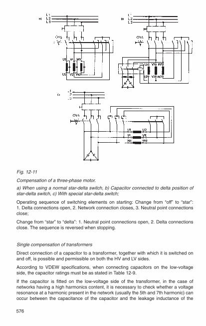
Fig. 12-11
Compensation of a three-phase motor.
a) When using a normal star-delta switch, b) Capacitor connected to delta position ofstar-delta switch, c) With special star-delta switch;
Operating sequence of switching elements on starting: Change from “off” to “star”:1. Delta connections open, 2. Network connection closes, 3. Neutral point connectionsclose;
Change from “star” to “delta”: 1. Neutral point connections open, 2. Delta connectionsclose. The sequence is reversed when stopping.
Single compensation of transformers
Direct connection of a capacitor to a transformer, together with which it is switched onand off, is possible and permissible on both the HV and LV sides.
According to VDEW specifications, when connecting capacitors on the low-voltageside, the capacitor ratings must be as stated in Table 12-9.
If the capacitor is fitted on the low-voltage side of the transformer, in the case ofnetworks having a high harmonics content, it is necessary to check whether a voltageresonance at a harmonic present in the network (usually the 5th and 7th harmonic) canoccur between the capacitance of the capacitor and the leakage inductance of the

12
577
transformer. The maximum capacitor rating can be defined approximately asSrT · 100 %
Qc < ———————ν2 · ukr
where SrT is the transformer rated power in kVA, and Qc the capacitor rating in kvar, andukr the rated impedance voltage (in per cent) of the transformer and the feedingnetwork, and v is the number of the highest critical harmonic.
Table 12-9
Capacitors connected on the low-voltage side of transformers
Transformer Transformer voltage, HV siderated power 5 to 10 kV 15 to 20 kV 25 to 30 kV
capacitor rating capacitor rating capacitor ratingkVA kvar kvar kvar
25 2 2.5 350 3.5 5 675 5 6 7
100 6 8 10160 10 12.5 15250 15 18 22315 18 20 24400 20 22.5 28630 28 32.5 40
Example:
In order to avoid resonance up to and including the 7th harmonic, for a 400 kVAtransformer and ukr = 6.2 %, the rating of the capacitor must definitely be less than
400 kVA · 100 %Qc < —————————— = 130 kvar
72 · 6.2 %
It must also be noted that the capacitor has the effect of raising the voltage. Under low-load conditions, this can lead to unwelcome increases in voltage if the capacitor ratingselected is more than covers the reactive current requirement of the transformer. Thevoltage at the capacitively loaded transformer then rises instead of falling. The increasecan be calculated with sufficient accuracy from
Qc∆ u ≈ ukr · ——.SrT
Single compensation of welding equipment
The capacitor rating for welding transformers and resistance welding machines can bebetween 30 and 50 % of the transformer rating. In the case of welding rectifiers, acapacitor rating of approximately 10% of the nominal rating is sufficient.

578
Fig. 12-12
Group compensation
Group compensation
The phase-shifting capacitor is connected to the distribution bus feeding, for example,a large number of small motors running continuously or intermittently, Fig. 12-12.
Short-circuit protection should consist of HV fuses, for each capacitor if required.Voltage transformers in V connection are necessary for discharging afterdisconnection.
Centralized compensation can be used for all voltages.
Fig. 12-13
Centralized compensation:
a) Total compensation, b) Compensation with automaticcontrol
The motors and capacitors are switched by separate switches and supervised byseparate protection systems. The capacitors can be switched on and off individually orin groups, as required.
Centralized compensation
In comparatively large installations with many small and medium-size loads (motors,etc.) which are not usually in operation at the same time, the phase-shifting capacitorsare connected centrally to the main busbar. The capacitors are switched either jointlyby hand (Fig. 12-13a) or automatically via regulators responding to time or reactive load(Fig. 12-13b).
Advantages: automatic control allows the capacitor rating to be closely matched to thereactive power required at any time, thus keeping cos ϕ closer to the specified value.
Disadvantage: distributing lines between busbar and points of consumption still carrythe same reactive current.
a) b)

12
579
12.4 Resistor devices
Resistor devices for low and high voltage are used in switchgear installations as
– Damping resistors for high-pass filters, in conjunction with arc suppression coils andfor limiting capacitive and inductive overvoltages,
– Earthing resistors for earthing the neutrals of transformers and generators and alsofor earth fault protection,
– Loading resistors,
– Voltage dividers,
– Discharge resistors for capacitors,
– Transition and series resistors for tap changers,
– Starting and braking resistors and rheostats for electric motors.
The live parts are in the form of wire or cast elements or corrugated sheet-steel lattices.These components are made up into assemblies with ceramic insulators and can takethe form of banks mounted on a frame.
Insulators are used for medium and high voltages.
In a resistor unit, electrical energy is converted into heat which the body of the resistorcan absorb only partly and only for a very short time. It must always be dissipated to theambient air. Resistor units are therefore usually air-cooled. Natural ventilation isgenerally sufficient. Separate ventilation or oil cooling is advisable in special cases.
The resistor elements normally have a tolerance of + 10 %. Smaller tolerances arepossible in special cases.
The rise in temperature, which can be up to about 400 K, increases the resistance. Withcast iron resistors, for example, the resistance increase is 7.5 %/100 K (Table 12-10).When the maximum temperature of about 400 °C is reached, a nominal initial current of600 A has fallen to 460 A.
Resistors are often not designed for a 100 % load factor, but only to operate for a limitedtime. If during this short period the load duration tB < Tϑ, a higher loading is permissible.The maximum load duration tBmax during which the resistor element heats up to thepermitted temperature limit with an overload of Ia = a · Ir, is
a2
tBmax = Tϑ · ln (———).a2 – 1
A sufficiently long interval must then follow to allow complete cooling.
Example:
Earthing resistors in medium and high-voltage installations for impedance earthing ofgenerator and transformer neutrals must limit the earth fault current to values of 0.5 to0.75 I"k3. The resulting values are no danger, particularly with regard to electricalmachines, and voltage rises due to any capacitive effects of network asymmetry areavoided. Also, in branched networks, a defined active current can be produced whichmakes it easier to measure and localize an earth fault. The load factor for theseearthing resistors is governed by the protective devices in question and their speed ofresponse.

580
Table 12-10
Characteristics of commercially available resistor elements
Form of resistor elementsCharacteristics Wire elements Cast iron Sheet steel grid
elements
Material CuNi44 Surface- Corrosion-(Constantan) treated resistantNiCr8020 cast iron steel sheet
CrNi alloysteel sheet
Resistance of 150–0.5 Ω 02–0.01 Ω 0.75–0.04 Ωindividual elementsat 20 °C
Continuous load 0.5–20 A3) 25–125 A3) 25–250 Acapacity of elements
Therm. time 20-90 s 240-600 s 120 sconstant Tϑ
Resistance increase 0.4%/100 K1) 7.5%/100 K 5%/100 K2)
with temperature
Insulation levelto housing 600 V/1 kV 1 kV 1 kVto earth across 3.6-52 kV 3.6-52 kV 3.6-52 kVinsulators
1) Resistance variation of CuNi44 (constantan) negligible. 2) For CrNi alloy sheet 2 % / 100 K. 3) Wire elements cease to be economical at about 15 A. From 25 A, use cast-metal or steel-sheet
elements.
For example, an earth resistor of this kind must limit the earth fault current to 400 A. Thefault is cleared quickly. Cast iron resistors are chosen with a continuous load capacityof Ir = 60 A. Their thermal time constant is Tϑ = 450 s. The maximum load duration isthus
a2 (400 /60)2
tBmax = Tϑ · ln (———) = 450 s · ln (————————) = 10.25 s.a2 – 1 (400 /60)2 –1
Such earthing resistors are usually sized to operate for 10 s.

12
581
12.5 Rectifiers
Semiconductor rectifiers are used exclusively today for rectifying alternating currents.
Rectifier assemblies are identified according to DIN VDE 0556. The identity codeshows the connection, rated connected voltage, rated DC voltage and rated DC currentof the assembly.
Example: Code letter for connection
Rated connected voltage in V
Rated DC voltage in V
Rated DC current in A
Code letter for assisted cooling(omitted with natural cooling)
F separate ventilationO oil cooling
B 275 / 220 – 10 or: S 400 / 224 – 162 F
If a rectifier assembly consists of several stacks (e.g. 4) a single stack is designated:
1/4 B 275 / 220 – 10
Table 12-11 shows a summary of calculation data for common rectifier circuits.The symbols denote the following:
u2 = Instantaneous value of applied AC voltage
U2 = Root-mean-square value of applied AC voltage
ug = Instantaneous value of rectified voltage
Ug = Arithmetic mean of rectified voltage
Ugo = Open-circuit DC voltage
ig = Instantaneous value of rectified current
Ig = Arithmetic mean of rectified current

582
Table 12-11
Basic calculation data for common rectifier connections
Connection to Alternating current 3-phase AC
Connection Half-wave Centre-tap Bridge Star 3-phase Double-starbridge
Circuit diagram Fig. 12-14 Fig. 12-16 Fig. 12-17 Fig. 12-18 Fig. 12-19 Fig. 12-20
No. of pulses p 1 2 2 3 6 6
Fundamental frequency of super-50 100 100 150 300 300imposed AC voltage (Hz)
Open-circuit DC voltage Ugo/U2 2 2 2 2 3 2 3 2 3 2–— = 0.45 –— = 0.45 –—— = 0.9 –—— = 0.67 –—— = 1.35 –—— = 0.67π π π 2 π π 2 π
Rating of each valve
as regards voltage for U2 U2 U2 U2 U2 U2
as regards current for Ig ¹₂Ig ¹₂Ig ¹₂Ig ¹₃Ig ¹₆Ig
Connected network power 2.69 1.23 1.23 1.23 1.05 1.05P1 / (Ugo · Ig) 1.111) 1.111)
Mean transformer rating 3.09 1.49 1.23 1.37 1.05 1.551.341) 1.111)
Voltage ripple(in % of Ugo) 121.1 48.3 48.3 18.3 4.2 4.2
1) For operation with inductive load (e.g. Iarge smoothing reactor)All other figures apply to purely resistive load.

12
583
Common rectifier connections
1. Half-wave connection, symbol E, see Fig. 12-14
The simplest of all rectifier connections. It consists of a branch which blocks onehalf-wave of the applied AC voltage. The result is a pulsating DC voltage with gapswhile the voltage is negative. This arrangement is normally used only for smallcurrents (often in conjunction with capacitors) and up to very high voltages with asuitable number of plates or stacks connected in series. The rectifier assembly mustblock the full transformer voltage and when capacitors are used, their chargingvoltage as well.
Fig. 12-15
Doubler connection a) Circuit diagram b) Voltage curve
2. Doubler connection, symbol V, see Fig. 12-15
This arrangement is again suitable only for small currents and relatively highvoltages. It always requires two capacitors which are charged in each half-cycle andwhen connected in series, produce at no-load a DC voltage corresponding to twicethe peak voltage of the applied AC voltage. Under load, the DC voltage decreasesaccording to the relationship between capacitance and load current. Each branch ofthe rectifier assembly has to block the sum of transformer voltage and capacitorvoltage.
3. Centre-tap connection, symbol M, see Fig. 12-16
This arrangement requires a transformer which has a centre tap on its secondarywinding. In the blocking direction, each branch carries the full transformer voltage.The connection is economical only for low voltages using the basic unit. For highervoltages requiring semiconductor devices to be connected in series, it is inferior to
Fig. 12-14
Half-wave connectiona) Circuit diagram b) Voltage curve

584
4. Bridge connection, symbol B, see Fig. 12-17.
Provided the voltages involved are not very low, in which case the centre-tapconnection may be preferable, the bridge connection is the most practical andeconomical over a wide range of currents and voltages, and therefore the mostcommonly used of all single-phase arrangements. In the blocking direction, each ofthe 4 branches is subjected to the full transformer voltage.
the following bridge connection because of the special transformer construction forthe same number of plates. It is then appropriate only if suitable transformers arealready available, i.e. when hot cathode or mercury vapour rectifiers are to bereplaced by semiconductor units.
Fig. 12-16
Centre-tap connection a) Circuit diagram b) Voltage curve
Fig. 12-17
Bridge connection a) Circuit diagram b) Voltage curve
Fig. 12-18
Star connection a) Circuit diagram b) Voltage curve
5. Star connection, symbol S, see Fig. 12-18.
This three-phase arrangement requires transformers, or networks in the case ofstraight connection, whose neutral is able to withstand the full direct current. Theconnection’s power rating is unlimited. However, it is practically used only whenmercury vapour rectifiers require replacement. Each branch is subjected to thephase-to-phase voltage. With voltages which exceed the nominal blocking voltage ofone rectifier device, the following three-phase bridge connection will probably bepreferable with the same number of devices. When directly linked to 380 Vthree-phase networks with loadable neutral, the star connection provides a DCvoltage of the order of 220 to 230 V.

12
585
Fig. 12-19
Three-phase bridge connection a) Circuit diagram b) Voltage curve
Fig. 12-20
Double-star connection a) Circuit diagram b) Voltage curve
7. Double-star connection, symbol DS, see Fig. 12-20
This arrangement corresponds to the centre-tap connection of the single-phaseconfigurations. Again, it is used almost exclusively only with low voltages requiringone basic unit, but currents can be high. With higher voltages, it can berecommended only when replacing the glass or iron cells of mercury vapourrectifiers. In the blocking direction, each of the 6 branches carries twice the phasevoltage.
6. Three-phase bridge connection, symbol DB, see Fig. 12-19
This is the most convenient and economical connection for all relatively high powersat voltages exceeding those of the basic star or double-star connections. Here again,each of the 6 branches carries the phase-to-phase voltage in the blocking direction.

586