122 the open construction and building technology journal ... · pdf fileing the possibility...
TRANSCRIPT

Send Orders for Reprints to [email protected]
122 The Open Construction and Building Technology Journal, 2014, 8, 122-131
1874-8368/14 2014 Bentham Open
Open Access
Mitigation of Progressive Collapse by the Activation of the Elasto-Plastic Catenary Behaviour of R.C. Slab Structures
Fabrizio Palmisano*
DICATECh, Politecnico di Bari, Via E. Orabona, 4, 70125, Bari, Italy
Abstract: Mitigation of progressive collapse was highlighted in 1968 with the collapse of the Ronan Point building in the
United Kingdom. Technical standards followed suit with increased requirements and recommendations to encourage the
design and construction of more robust buildings. The intent has been to establish a design process that recognizes and
considers the potential that buildings could experience abnormal and extreme loads or events that seriously compromise
one or more critical load-carrying elements.
This article aims to show that if the main goal of the design is to protect human lives in these extreme conditions, even
sacrificing the building functionality, simple measures such as the activation of the elasto-plastic catenary behaviour of
the slab reinforcement, could be very effective to increase the building robustness without substantially increasing the cost
of a structural system.
Keywords: Catenary action, load path method, progressive collapse, R.C. structures, robustness, slab structures.
1. INTRODUCTION
The 1968 Ronan Point collapse (Fig. 1) has been instru-mental [1] in making engineers aware of the possibility of a chain reaction or progressive collapse. Its importance, how-ever, has been growing because of the spread of many tragic collapses: the Murrah Federal Building in Oklahoma (1995), the Giotto Avenue Building in Foggia (1999), the World Trade Centre in New York (2001).
ASCE 7-10 [2] defines the progressive collapse as “the spread of an initial local failure from element to element resulting, eventually, in the collapse of an entire structure or a disproportionately large part of it”.
In a design to prevent progressive collapse, the triggering event is unknown; local failure is caused by ‘abnormal load-ings’ that are loads which are not normally considered in design. These include:
• pressure loading due to explosions;
• impact caused by vehicles, aeroplanes, construction cranes, falling debris, etc.;
• natural hazards (not considered in design) such as fires, floods, tornadoes, etc.;
• design and construction errors.
Even though it is necessary to consider that nature and intensity of the external action that triggers the collapse could have an influence on the failure propagation, in the search for effective design remedies, the separation between the two problems, failure initiation and propagation, could be
*Address correspondence to this author at the DICATECh, Politecnico di
Bari, Via E. Orabona, 4, 70125, Bari, Italy;
Tel: +39-0805963770; Fax: +39-0805417502;
E-mail: [email protected]
useful. The aim should be to give every building an intrinsic capacity to limit damages caused by a local failure not de-pending on the triggering event.
Fig. (1). The Ronan Point collapse.
ASCE 7-10 [2] defines two general approaches for reduc-
ing the possibility of progressive collapse: ‘Direct Design’ and ‘Indirect Design’.

Mitigation of Progressive Collapse by the Activation The Open Construction and Building Technology Journal, 2014, Volume 8 123
The Direct Design approach includes "explicit considera-tion of resistance to progressive collapse during the design process…". These include: the Alternate Path (AP) method, which requires that the structure be capable of bridging over a missing structural element, with the resulting extent of damage being localized, and the Specific Local Resistance (SLR) method, which requires that the building, or parts of the building, provide sufficient strength to resist a specific load or threat.
With the Indirect Design, resistance to progressive col-lapse is considered implicitly "through the provision of minimum levels of strength, continuity and ductility". The ASCE 7-10gives general design guidelines and suggestions for improving structural integrity. However, no quantitative requirements for either direct or indirect design to resist pro-gressive collapse are provided in this code.
UK [3] was the first country to address progressive col-lapse explicitly in its building standards after the Ronan Point collapse. The British Standards employ three design approaches to resist progressive collapse:
• Tie Forces (TF). This indirect design approach enhances continuity, ductility, and structural redundancy by requir-ing ‘ties’ to keep the structure together in the event of an abnormal loading.
• Alternate Path (AP). This direct method requires that the designer prove that the structure is capable of bridging over a removed structural element and that the resulting extent of damage does not exceed the damage limits. The missing structural element is any element that cannot provide an adequate vertical tie force.
• Specific Local Resistance (SLR). This direct method requires that, for any structural element over which the building cannot bridge, the element must be designed as a ‘key’ or ‘protected’ element, capable of carrying a static pressure loading of 34 kPa.
The approach of the Eurocodes is more articulated.
The EN1990 [4] (i.e. the first part of the Eurocodes that gives the basis of structural design) says that “a structure shall be designed and executed in such a way that it will not be damaged by events such as explosion, impact, and the consequences of human errors to an extent disproportionate to the original cause”. It also gives general design guidelines. According to EN 1990, the other Eurocodes should give spe-cific rules to reduce the risk of progressive collapse. For ex-ample, the Eurocode 2 [5] gives some rules to provide, in R.C. buildings, a minimum amount of horizontal and vertical ties.
In this context, the latest release of Part 1-7 of Eurocode 1 [6], contains in its Annex A (i.e. "Project of the buildings for the consequences of a local failure resulting from a cause not specified") the most innovative part of all the Eurocodes. It provides a categorisation of building types/occupancies to four consequences classes and recommends for each class a specific design strategy in order to give a building an accept-able level of robustness to sustain localised failure without a disproportionate level of collapse.
According to the present codes of practice, the designer should give the structure a minimum level of continuity, re-
dundancy and ductility and should perform progressive col-lapse analyses that consider the loss of portions of the struc-ture in numerous ‘missing column’ scenarios [7]. For com-mon buildings (e.g. not federal) the main aim of this particu-lar kind of design should be to protect human lives in ex-treme conditions. This means that, to remain economically viable, this additional design requirement must typically be incorporated without relevant increase in the cost of the structural system. The only way to achieve this goal is to completely sacrifice the building functionality in these ex-treme conditions and to use large deformations caused by the initiation of a failure to activate other resistant mechanisms.
2. THE INTERPRETATION OF THE ‘MISSING COL-UMN’ SCENARIO BY USING THE LOAD PATH
METHOD
In R.C. buildings, the estimated final damage caused by a progressive collapse phenomenon is proportional to the original damage extension. The larger this extension be-comes, the lower the probability to activate alternate load paths becomes, because a large bypass of the damaged area needs a large strain energy investment that can be achieved only by large building deformations. In a R.C. building, col-umns are the structural elements that have the largest amount of strain energy invested by loads to bypass the area where the first rupture has occurred.
Born as a method to design Strut-and-Tie Models in rein-forced concrete structures, the Load Path Method (LPM hereafter) was introduced by Schlaich et al. [8] and then de-veloped mainly by F. Palmisano and A. Vitone (e.g. [9]-[12]). So far the Load Path Method has been used for a wide range of applications: reinforced concrete structures [8], ma-sonry structures ([13-21]), special structures [22], seismo-resistant structures ([23, 24]), conceptual and detailing de-sign [25], detailing, optimum design [12], assessment of ex-isting constructions [11].
The Load Path Method is a clear and effective technical instrument of investigation and judgement. Not only a nu-merical, but also a geometrical method that predicts the re-sults of the calculations disclosing the shape aspects from which it is possible to recognise the real structural behaviour.
In this paragraph, the interpretation of the ‘missing col-umn’scenario by using the Load Path Method, is presented [25]. The LPM gives an immediate perception, simple but complete, of the involved elements (i.e. structures and walls) and of the forces intensity.
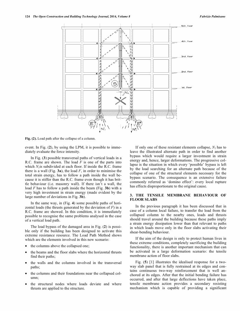
In Fig. (2) the case of the first floor column collapse is showed. To immediately catch the intensity of the actions and which are the involved elements, in Fig. (2), preliminar-ily, the presence of infill walls in the R.C. frame has been assumed.
The load N1 has to go up in the search for a path through the adjacent columns to invest the minimum amount of strain energy. The loads, in every deviation nodes, give horizontal thrusts to the structure. This scenario demonstrates that a column collapse creates, in the floors, forces similar to those generated by an earthquake. These forces often produce ef-fects more disastrous than the earthquake ones because, even if localized, they strike on buildings not prepared for the
124 The Open Construction and Building Technology Journal, 2014, Volume 8 Fabrizio Palmisano
Fig. (2). Load path after the collapse of a column.
event. In Fig. (2), by using the LPM, it is possible to imme-diately evaluate the force intensity.
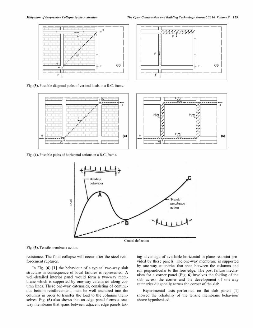
In Fig. (3) possible transversal paths of vertical loads in a R.C. frame are shown. The load F is one of the parts into which N1is subdivided at each floor. If inside the R.C. frame there is a wall (Fig. 3a), the load F, in order to minimise the total strain energy, has to follow a path inside the wall be-cause it is stiffer than the R.C. frame even though it has brit-tle behaviour (i.e. masonry wall). If there isn’t a wall, the load F has to follow a path inside the beam (Fig. 3b) with a very high investment in strain energy (made evident by the large number of deviations in Fig. 3b).
In the same way, in (Fig. 4) some possible paths of hori-zontal loads (the thrusts generated by the deviation of F) in a R.C. frame are showed. In this condition, it is immediately possible to recognise the same problems analysed in the case of a vertical load path.
The load bypass of the damaged area in Fig. (2) is possi-ble only if the building has been designed to activate this extreme resistance resource. The Load Path Method shows which are the elements involved in this new scenario:
• the columns above the collapsed one;
• the beams and the floor slabs where the horizontal thrusts find their paths;
• the walls and the columns involved in the transversal paths;
• the columns and their foundations near the collapsed col-umn;
• the structural nodes where loads deviate and where thrusts are applied to the structure.
If only one of these resistant elements collapse, N1 has to leave the illustrated alternate path in order to find another bypass which would require a larger investment in strain energy and, hence, larger deformations. The progressive col-lapse is the situation in which every ‘possible’ bypass is left by the load searching for an alternate path because of the collapse of one of the structural elements necessary for the bypass scenario. The consequence is an extensive failure commonly referred as ‘domino effect’: every local rupture has effects disproportionate to the original cause.
3. THE TENSILE MEMBRANE BEHAVIOUR OF FLOOR SLABS
In the previous paragraph it has been discussed that in case of a column local failure, to transfer the load from the collapsed column to the nearby ones, loads and thrusts should travel around the building because these paths imply a strain energy dissipation lower than that relevant to paths in which loads move only in the floor slabs activating their shear-bending behaviour.
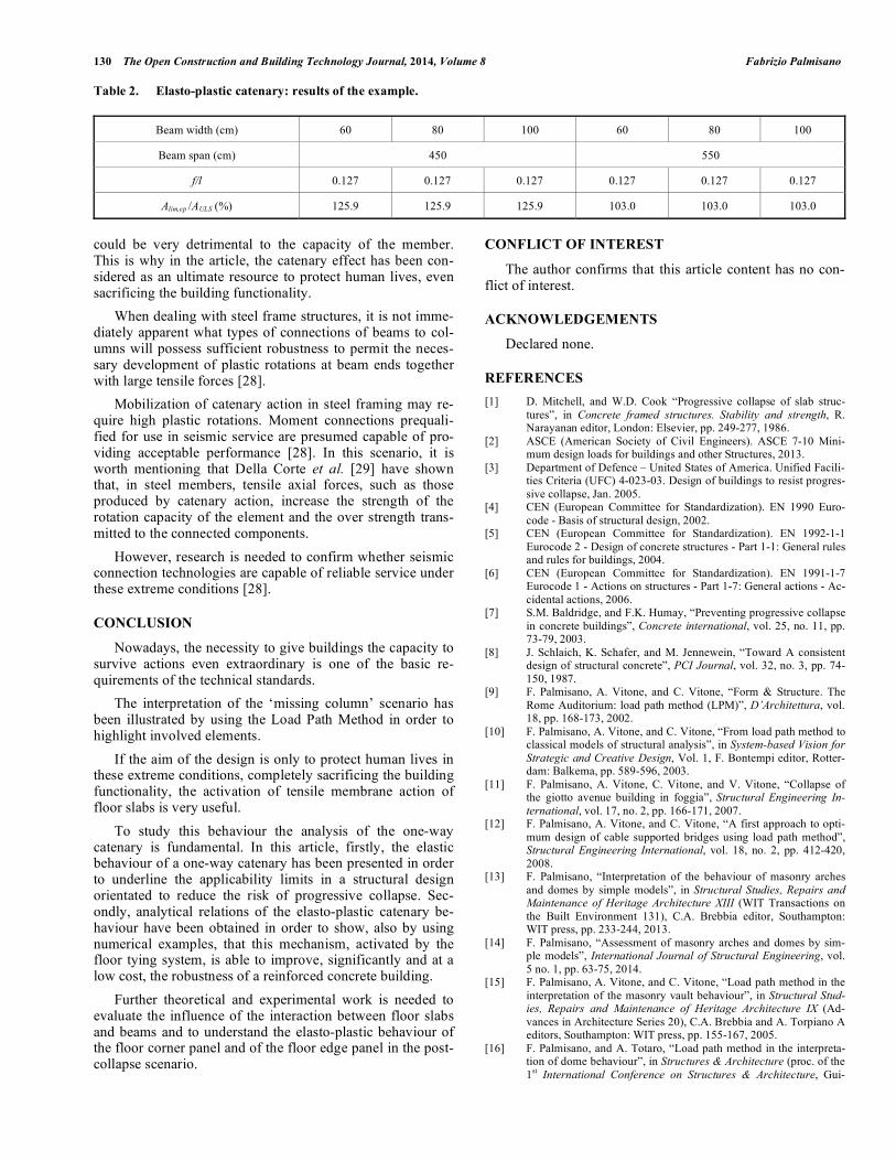
If the aim of the design is only to protect human lives in these extreme conditions, completely sacrificing the building functionality, there is another important mechanism that can be activated in a large deformation scenario: the tensile membrane action of floor slabs.
Fig. (5) [1] illustrates the idealised response for a two-way slab panel that is fully restrained at its edges and con-tains continuous two-way reinforcement that is well an-chored at its edges. After that the initial bending failure has occurred, and after that large deflections have taken place, tensile membrane action provides a secondary resisting mechanism which is capable of providing a significant
Mitigation of Progressive Collapse by the Activation The Open Construction and Building Technology Journal, 2014, Volume 8 125
Fig. (3). Possible diagonal paths of vertical loads in a R.C. frame.
Fig. (4). Possible paths of horizontal actions in a R.C. frame.
Fig. (5). Tensile membrane action.
resistance. The final collapse will occur after the steel rein-forcement ruptures.
In Fig. (6) [1] the behaviour of a typical two-way slab structure in consequence of local failures is represented. A well-detailed interior panel would form a two-way mem-brane which is supported by one-way catenaries along col-umn lines. These one-way catenaries, consisting of continu-ous bottom reinforcement, must be well anchored into the columns in order to transfer the load to the columns them-selves. Fig. (6) also shows that an edge panel forms a one-way membrane that spans between adjacent edge panels tak-
ing advantage of available horizontal in-plane restraint pro-vided by these panels. The one-way membrane is supported by one-way catenaries that span between the columns and run perpendicular to the free edge. The post failure mecha-nism for a corner panel (Fig. 6) involves the folding of the slab across the corner and the development of one-way catenaries diagonally across the corner of the slab.
Experimental tests performed on flat slab panels [1] showed the reliability of the tensile membrane behaviour above hypothesised.

126 The Open Construction and Building Technology Journal, 2014, Volume 8 Fabrizio Palmisano
Fig. (6). Tensile membrane behaviour of a floor slab.
Mitchell and Cook [26], assuming that a tensile mem-
brane takes a circular deformed shape and neglecting any flexural resistance, developed a design expression for the amount of reinforcement in the one-way catenary by assum-ing that the one-way catenary is subjected to a uniform load equal to 0.5 wl2 per unit length where:
• w is the uniformly distributed load;
• l2 is the distance measured from the centreline of the panel on one side of the catenary to the centreline of the panel on the other side of the catenary.
If a limiting deflection of 0.15 ln is chosen for the one-way catenary (of clear span ln), the force in the anchored bottom reinforcement in the one-way catenary is
Tc= 0.465wl
nl2 (1)
The design and detailing recommendations by Mitchell and Cook were incorporated in the Canadian Standards As-sociation Code and in ACI 352.1R-89. The area of continu-ous bottom steel Asb required in the direction ln is
Asb =0.5wslnl2
s fy (2)
where
• Asb = minimum area of effectively continuous bottom bars in the direction ln placed over the support;
• ws = factored uniformly distributed load to be carried after the initial failure;
• ln = clear span in the considered direction, measured face-to-face of the supports;
• l2 = distance measured from the centreline of the panel on one side of the catenary to the centreline of the panel on the other side of the catenary;
• fy = specified yield strength of reinforcement;
• s = strength reduction factor for reinforcing bars.
3. THE ONE-WAY CATENARY
As above illustrated, to study the tensile membrane be-haviour, the analysis of the one-way catenary is fundamental. In paragraph 3.1 the elastic behaviour of a one-way catenary is presented to highlight its applicability limits in a structural design orientated to reduce the risk of progressive collapse in the respect of the goals showed in the previous paragraphs. From these conclusions, the necessity of an elasto-plastic approach arises and it is analysed in paragraph 3.2.
3.1. The Elastic Behaviour
In the first step of the analysis an elastic steel catenary of area A and modulus of elasticity Es, perfectly flexible, able to resist only to tensile normal force, loaded with a uniform vertical load q(per unit length) from the top to the bottom is considered (Fig. 7). It is supported by two fix hinges, and in the undeformed configuration is horizontal and of span l; in the deformed configuration one of the supports (left in Fig. 7) undergoes a vertical settlement h.
Fig. (7). Geometry of the elastic catenary.
The cable is stressed by a tensile normal force N(x) that
has vertical and horizontal components V(x) and H(x), where, for vertical loads, H(x) is constant.
From general equilibrium conditions

Mitigation of Progressive Collapse by the Activation The Open Construction and Building Technology Journal, 2014, Volume 8 127
dV
dx= q (3)
V = Hdy
dx= Hy ' (4)
Hd2y
dx2= Hy '' = q (5)
From integration, imposing the boundary conditions
y(0)=h and y(l)=0, it results
y =q
2Hx(l x) +
h
l(l x) (6)
It is possible to notice that this parabola has its apex for
x = c =l
2
Hh
ql (7)
The apex is between the two supports only if H is not too
high; in this case the maximum deflection is
y(c) =ql
2
8H+h
2+
h
l
2H
2q (8)
In the other case, the maximum deflection is equal to the vertical movement h of the support that has undergone a ver-tical settlement.
Varying H it is possible to find a cable configuration that respects the equilibrium conditions (5), but there is only one configuration that respects also the consistency of the cable deformation with the condition that its elongation is equal to the elastic extension allowed by its mechanical characteris-tics.
The length of the deformed cable is
L = 1+ (y ')2dx
0
l
(9)
Assuming
a =ql
2H
h
l (10)
b =q
H (11)
then
y ' = a bx (12)
L =l
2
a
2b1+ a bl( )
2
sinh1(a bl)
2b+a
2b1+ a
2+sinh
1a
2b
(13)
and the catenary total elongation lg is
lg = L l =l
2
a
2b1+ a bl( )
2
sinh1(a bl)
2b+a
2b1+ a
2+sinh
1a
2bl
(14)
The catenary elastic extension le is
le =N s( )EsA
ds =0
LH
EsA1+ (y ')
2( ) dx =0
lHl
EsA1+
q2l
2
12H2+h
2
l2
(15)
Making equal the geometrical elongation and the elastic one it is possible to obtain the consistency relation:
L l =Hl
EsA1+
q2l2
12H2+h2
l2
(16)
This equation allows to obtain the only value of H that
gives a consistent and equilibrated solution which can be
allowable only if the maximum axial stress in the cable fs,max
is not higher than the design yield strength of the reinforce-
ment in the post-collapse conditions fydPCLS
(for the definition
of the post-collapse conditions see in the following).
The maximum axial strain Nmax in the catenary is
Nmax
= N(l) = H 1+ y ' l( )2= H 1+
q2l2
4H2+qh
H+h2
l2
(17)
then it is necessary to check that
fs,max =Nmax
AfydPCLS (18)
If this relation is not satisfied, the area A of the cable is not sufficient to guarantee a completely elastic behaviour.
Assuming the values of l, h and q, it is possible to obtain the only value Alim,e of A, that corresponds to an elastic catenary with a maximum axial stress equal to the design yield strength. If the area of the catenary is lower than Alim,e
there is no configuration with the cable totally elastic, even though a solution with an elasto-plastic behaviour exists.
Using the obtained equations it is possible to analyse the behaviour of a beam in the ‘missing column’ scenario.
Taking into account that, in these extreme conditions, the aim of the design is only to protect human lives completely sacrificing the building functionality, the examined scenario cannot be considered as a common ultimate limit state (ULS hereafter). It could be defined as a ‘post-collapse’ limit state (PCLS hereafter) where the wording ‘post-collapse’ aims to highlight that these conditions follow the shear-bending fail-ure of the beam which is assumed as the ‘collapse’ at the ULS. The PCLS has a probability of occurrence, during the structure design working life, surely lower than the one usu-ally associated with the ULS. As a consequence, partial fac-tors (for materials and actions) different from the ones used at the ULS have to be assumed.
In the case under study, it has been assumed that the ini-tiation of the phenomenon is the failure of a floor internal column and that the beam, which has lost one of its supports, has to behave like a catenary with span l equal to the dis-tance between the two not-collapsed supports. It has been assumed that the floor slab does not give any kind of support to the beam at the PCLS and that the part of the floor slab which is borne by the beam at the PCLS is the same as that borne at the ULS.
As an example, the case of a beam 30 cm deep, with an effective depth of the cross section equal to 25 cm, designed for bending action at the ULS with a ratio of the depth of the neutral axis to the effective depth x/d=0.35, is considered. If

128 The Open Construction and Building Technology Journal, 2014, Volume 8 Fabrizio Palmisano
Gk is the permanent load and Qk is the variable load, varying its width B and its span lT (at the ULS, before the failure of the column) it is possible to evaluate the maximum uni-formly distributed load
qULS = g
ULSGk + q
ULSQk
(19)
that the beam can bear at the ULS in the hypothesis that its resistant bending moment is exactly the same as its exter-nal acting bending moment
MEd ,MAX
SLU=1
KqULSlT
2 (20)
Considering the case of an internal bay, it has been as-sumed K=16 [27].
According to [3], in the case of linear and nonlinear static analysis, the load combination for alternate path at the PCLS is
qPCLS = d
PCLS
g
PCLSGk + q
PCLSQk( ) (21)
In this example it has been assumed
Gk
Qk
= 4 (22)
and, according to [4],
g
ULS= 1.35 (23)
q
ULS= 1.5 (24)
Taking into account that the aim of the design is only to protect human lives at the PCLS, completely sacrificing the building functionality, the partial factor for permanent and variable loads given by the Annex A of [6] have been as-sumed:
g
PCLS= 1 (25)
q
PCLS PCLS= 1 0.3 = 0.3 (26)
In order to account for amplification in the response to dynamic effects that can occur when a structural element is violently removed from a structure, the load combination at the PCLS is multiplied by the factor [3]
d
PCLS= 2 (27)
According to Eurocode 2 [5], these assumptions for con-crete have been made:
fck=30 MPa (28)
c
ULS= 1.5 (29)
cc
ULS= 0.85 (30)
It has been assumed a Class C [5] steel reinforcement with
fyk= 450 MPa (31)
Es= 200 GPa (32)
with these partial factors (taken from [5] and [3] respec-tively):
s
ULS= 1.15 (33)
s
PCLS= 0.8 (34)
considering that
fydULS
=fyk
s
ULS (35)
fydPCLS
=fyk
s
PCLS (36)
The cases of beam width equal to 60 cm, 80 cm, 100 cm and span equal to 450 cm and 550 cm are illustrated assum-ing that the catenary span l is twice the beam span lT. In Table 1 the relative catenary ratio f/l, the ratio of the Alim,e to the amount of reinforcement AULS necessary in the middle of the span at the bottom of the beam at the ULS for the bend-ing moment, are reported.
From Table 1, it is possible to observe that to guarantee a totally elastic catenary at the PCLS, it is necessary to place an amount of beam bottom reinforcement, continuous from support to support, extremely larger than the one strictly necessary at the ULS. This means that this solution is not economically viable. The only way to reduce the reinforce-ment amount is to accept a catenary elasto-plastic behaviour.
3.2. The Elasto-Plastic Behaviour
Differently from the assumptions of the case of the to-tally elastic cable, for the elasto-plastic catenary the de-formed configuration has no vertical settlement of the sup-ports.
The Eurocode [5] reinforcing steel stress-strain relation has been assumed (Fig. 8).
Assuming the values of l, q and a value of A lower than
Alim,e, the catenary has still a parabola shape because of gen-
eral equilibrium conditions. The central part remains in the elastic range (depending on the amount of A) while the lat-
eral parts are yielded (Fig. 9).
Table 1. Elastic catenary: results of the example.
Beam width (cm) 60 80 100 60 80 100
Beam span (cm) 450 550
f/l 0.033 0.033 0.033 0.033 0.033 0.033
Alim,e /AULS (%) 511.2 511.2 511.2 418.3 418.3 418.3

Mitigation of Progressive Collapse by the Activation The Open Construction and Building Technology Journal, 2014, Volume 8 129
Fig. (8). Design stress-strain relation for reinforcing steel.
Fig. (9). Geometry of the elasto-plastic catenary.
These assumptions have been made:
• L = total length of the deformed cable;
• m = horizontal projection of the elastic part;
• r = horizontal projection of one of the lateral yielded part;
• M = length of the deformed elastic part;
• R = length of one of the deformed lateral yielded part.
It is possible to observe that:
l = m + 2r (37)
L = M + 2R (38)
From general equilibrium conditions
H =ql
2
8 f (39)
Nmax
= H 1+q2l2
4H2
(40)
Because of consistency, the cable elongation lg (14) is equal to the elasto-plastic elogation lep allowed by the steel mechanical characteristics. It is possible to observe that the total catenary is the union of three cables (the two yielded lateral ones and the central elastic one) that have the same value H for the horizontal component of N(x).
The vertical position of the extreme nodes of the elastic central part is (Fig. 9)
y(r) = y(l r) = hr =q
2Hr(l r) (41)
If lm the elastic elongation of the central part and lr the elasto-plastic elongation of one of the lateral parts, it is pos-sible to obtain
lep = lm + 2 lr (42)
with
lm =H
EsAm +
q2m3
12H2
=H
EsAl 2r +
q2(l 2r)
3
12H2
(43)
lr = s( )ds =0
R
yd + s( )( )ds =0
R
ydR + s( )ds =0
R Nyd
EsAR +
N s( ) Nyd
EyAds =
0
R
=Nyd
AR
1
Es
1
Ey
+N s( )EyA
ds =0
R Nyd
AR
1
Es
1
Ey
+H
EyAr +
q2r
3
12H2+q
2r
4H2l r( )
2
(44)
where R can be evaluated, as a function of r, by using (13) and
Nyd = AfydPCLS (45)
Finally (40), (41) and (43) solve the analysis of the elasto-plastic catenary.
If
Alim,ep =
Nmax
ftdPCLS
(46)
assuming l, q, f and a value of A that is lower than Alim,e and larger than Alim,ep it is possible to obtain r from (39), (40) and (42). If r>l/2 there is no solution for the assumed value of f.
If r = l/2 (totally yielded cable) is assumed, from (39), (40) and (42) it is possible to evaluate Alim,ep and the corre-sponding value of f.
As an example, the same cases analysed for the totally elastic catenary are illustrated in Table 2 assuming a totally yielded catenary and the following reinforcement stress-strain parameters according to Fig. 8:
k =ft
fy k
= 1.15 (47)
uk= 7.5% (48)
ud=
uk (49)
It can be observed that the amount of the continuous bot-tom steel Alim,ep is compatible with the aim to significantly improve the robustness of the building without any substan-tial increase in the cost of the structural system. Looking at the values of f/l in Table 2, it is also possible to notice that they are totally consistent with the necessity to guarantee the survival of people staying at the floor just below the consid-ered beam in a common residential building. If, in other cases, from the elasto-plastic analysis with a totally yielded catenary, the calculated value of f is too high, the only possi-bility is to increase the amount of reinforcement in order to reduce the yielded part and consequently f.
4. CATENARY ACTIONS IN R.C. AND STEEL STRUCTURES
Even though the aim of the article is to show the efficacy of elasto-plastic catenary behaviour in R.C. structures, some considerations about the difference between R.C. and steel structures seem to be necessary.
The catenary effect produces large tensile forces in beams. As above-mentioned, in case of R.C. beams, this
130 The Open Construction and Building Technology Journal, 2014, Volume 8 Fabrizio Palmisano
Table 2. Elasto-plastic catenary: results of the example.
Beam width (cm) 60 80 100 60 80 100
Beam span (cm) 450 550
f/l 0.127 0.127 0.127 0.127 0.127 0.127
Alim,ep /AULS (%) 125.9 125.9 125.9 103.0 103.0 103.0
could be very detrimental to the capacity of the member. This is why in the article, the catenary effect has been con-sidered as an ultimate resource to protect human lives, even sacrificing the building functionality.
When dealing with steel frame structures, it is not imme-diately apparent what types of connections of beams to col-umns will possess sufficient robustness to permit the neces-sary development of plastic rotations at beam ends together with large tensile forces [28].
Mobilization of catenary action in steel framing may re-quire high plastic rotations. Moment connections prequali-fied for use in seismic service are presumed capable of pro-viding acceptable performance [28]. In this scenario, it is worth mentioning that Della Corte et al. [29] have shown that, in steel members, tensile axial forces, such as those produced by catenary action, increase the strength of the rotation capacity of the element and the over strength trans-mitted to the connected components.
However, research is needed to confirm whether seismic connection technologies are capable of reliable service under these extreme conditions [28].
CONCLUSION
Nowadays, the necessity to give buildings the capacity to survive actions even extraordinary is one of the basic re-quirements of the technical standards.
The interpretation of the ‘missing column’ scenario has been illustrated by using the Load Path Method in order to highlight involved elements.
If the aim of the design is only to protect human lives in these extreme conditions, completely sacrificing the building functionality, the activation of tensile membrane action of floor slabs is very useful.
To study this behaviour the analysis of the one-way catenary is fundamental. In this article, firstly, the elastic behaviour of a one-way catenary has been presented in order to underline the applicability limits in a structural design orientated to reduce the risk of progressive collapse. Sec-ondly, analytical relations of the elasto-plastic catenary be-haviour have been obtained in order to show, also by using numerical examples, that this mechanism, activated by the floor tying system, is able to improve, significantly and at a low cost, the robustness of a reinforced concrete building.
Further theoretical and experimental work is needed to evaluate the influence of the interaction between floor slabs and beams and to understand the elasto-plastic behaviour of the floor corner panel and of the floor edge panel in the post-collapse scenario.
CONFLICT OF INTEREST
The author confirms that this article content has no con-flict of interest.
ACKNOWLEDGEMENTS
Declared none.
REFERENCES
[1] D. Mitchell, and W.D. Cook “Progressive collapse of slab struc-
tures”, in Concrete framed structures. Stability and strength, R. Narayanan editor, London: Elsevier, pp. 249-277, 1986.
[2] ASCE (American Society of Civil Engineers). ASCE 7-10 Mini-mum design loads for buildings and other Structures, 2013.
[3] Department of Defence – United States of America. Unified Facili-ties Criteria (UFC) 4-023-03. Design of buildings to resist progres-
sive collapse, Jan. 2005. [4] CEN (European Committee for Standardization). EN 1990 Euro-
code - Basis of structural design, 2002. [5] CEN (European Committee for Standardization). EN 1992-1-1
Eurocode 2 - Design of concrete structures - Part 1-1: General rules and rules for buildings, 2004.
[6] CEN (European Committee for Standardization). EN 1991-1-7 Eurocode 1 - Actions on structures - Part 1-7: General actions - Ac-
cidental actions, 2006. [7] S.M. Baldridge, and F.K. Humay, “Preventing progressive collapse
in concrete buildings”, Concrete international, vol. 25, no. 11, pp. 73-79, 2003.
[8] J. Schlaich, K. Schafer, and M. Jennewein, “Toward A consistent design of structural concrete”, PCI Journal, vol. 32, no. 3, pp. 74-
150, 1987. [9] F. Palmisano, A. Vitone, and C. Vitone, “Form & Structure. The
Rome Auditorium: load path method (LPM)”, D’Architettura, vol. 18, pp. 168-173, 2002.
[10] F. Palmisano, A. Vitone, and C. Vitone, “From load path method to classical models of structural analysis”, in System-based Vision for
Strategic and Creative Design, Vol. 1, F. Bontempi editor, Rotter-dam: Balkema, pp. 589-596, 2003.
[11] F. Palmisano, A. Vitone, C. Vitone, and V. Vitone, “Collapse of the giotto avenue building in foggia”, Structural Engineering In-
ternational, vol. 17, no. 2, pp. 166-171, 2007. [12] F. Palmisano, A. Vitone, and C. Vitone, “A first approach to opti-
mum design of cable supported bridges using load path method”, Structural Engineering International, vol. 18, no. 2, pp. 412-420,
2008. [13] F. Palmisano, “Interpretation of the behaviour of masonry arches
and domes by simple models”, in Structural Studies, Repairs and Maintenance of Heritage Architecture XIII (WIT Transactions on
the Built Environment 131), C.A. Brebbia editor, Southampton: WIT press, pp. 233-244, 2013.
[14] F. Palmisano, “Assessment of masonry arches and domes by sim-ple models”, International Journal of Structural Engineering, vol.
5 no. 1, pp. 63-75, 2014. [15] F. Palmisano, A. Vitone, and C. Vitone, “Load path method in the
interpretation of the masonry vault behaviour”, in Structural Stud-ies, Repairs and Maintenance of Heritage Architecture IX (Ad-
vances in Architecture Series 20), C.A. Brebbia and A. Torpiano A editors, Southampton: WIT press, pp. 155-167, 2005.
[16] F. Palmisano, and A. Totaro, “Load path method in the interpreta-tion of dome behaviour”, in Structures & Architecture (proc. of the
1st International Conference on Structures & Architecture, Gui-
Mitigation of Progressive Collapse by the Activation The Open Construction and Building Technology Journal, 2014, Volume 8 131
marães, Portugal, 21-23 July 2010), P.J.S. Cruz editor, Leiden:
CRC Press/Balkema, pp. 1826-1833, 2010. [17] F. Palmisano, and A. Elia, “Masonry buildings subjected to founda-
tion settlements due to landslide: a preliminary study on the inter-pretation of structural behaviour using load path method”, Struc-
tural Studies, Repairs and Maintenance of Heritage Architecture XI (WIT Transactions on the Built Environment 109), C.A. Brebbia
editor, Southampton: WIT press, pp. 141-150, 2009. [18] F. Palmisano, and A. Elia, “Analysis of the structural behaviour of
masonry buildings subjected to landslide by using the Load Path Method”, International Journal of Earth Sciences and Engineering,
vol. 6, no. 1, pp. 39-49, 2013. [19] F. Palmisano, and A. Elia, “Structural behaviour of masonry build-
ings subjected to landslide: load path method approach”, in Struc-tures and Architecture: New concepts, applications and challenges
(proc. of the 2nd International Conference on Structures & Archi-tecture, Guimarães, Portugal, 24-26 July 2013), P.J.S. Cruz editor,
Leiden: CRC Press/Balkema, pp. 888-895, 2013. [20] F. Palmisano, and A. Elia, “Behaviour of masonry buildings sub-
jected to landslide-induced settlements”, International Journal of Structural Engineering, vol. 5, no. 2, pp. 93-114, 2014.
[21] F. Palmisano, and A. Elia, “Assessment of masonry buildings sub-jected to landslide by using the Load Path Method”, International
Journal of Civil Engineering, vol. 12, no. 2, pp. 312-330, 2014. [22] H. Shi, Q. Wang, F. Wei, and L. Shen, “Load path analysis of a
floating concrete gate using finite element method”, Structural En-gineer, vol. 6, no. 91, pp. 38-41, 2013.
[23] M. Mezzina, F. Palmisano, and D. Raffaele, “The design of r.c. bridge deck subjected to horizontal actions by strut-and-tie model”,
in Bridge Maintenance, Safety, Management and Life-Cycle Opti-
mization (proc. of the 5th International Conference on Bridge Main-tenance, Safety and Management – IABMAS 2010, Philadelphia,
Pensylvania, USA, July 11-15 2010), D.M. Frangopol, R. Sause, C.S. Jusko editors, London: Taylor & Francis Group, pp. 2390-
2397, 2010. [24] M. Mezzina, F. Palmisano, and D. Raffaele, “Designing simply
supported R.C. bridge decks subjected to in-plane actions: Strut-and-Tie Model approach”, Journal of Earthquake Engineering, vol.
16, no. 4, pp. 496-514, 2012. [25] F. Palmisano, “Form and structure in the harmonious complexity of
the building process: from conceptual design to detailing in some reinforced concrete works”, Structural Concrete, vol. 6, no. 3, pp.
122-130, 2005. [26] D. Mitchell, and W.D. Cook, “Preventing progressive collapse of
slab structures”, Journal of the structural division, vol. 110, no. 7, pp. 1513-1532, 1984.
[27] I.M. Alsamsam, and M.E. Kamara, Simplified design. Reinforced concrete buildings of moderate size and height, Skokie, USA: Port-
land Cement Association, 2004. [28] R. Hamburger, and A. Whittaker, “Design of Steel Structures for
Blast-Related Progressive Collapse Resistance”, In: Proc. of the North American Steel Construction Conference (NASCC), Long
Beach, CA, USA, 2004, pp. 42-53. [29] G. Della Corte, M. D’Aniello, and R. Landolfo, “Analytical and
numerical study of plastic overstrength of shear links”, Journal of Constructional Steel Research, vol. 82, pp. 19-32, 2013.
Received: June 15, 2014 Revised: June 30, 2014 Accepted: July 01, 2014
© Fabrizio Palmisano; Licensee Bentham Open.
This is an open access article licensed under the terms of the Creative Commons Attribution Non-Commercial License (http://creativecommons.org/-
licenses/by-nc/3.0/) which permits unrestricted, non-commercial use, distribution and reproduction in any medium, provided the work is properly cited.