document13
TRANSCRIPT

Performance Analysis of Phase Noise Impaired
OFDM SysteminaMultipath Fading Channel
Joseph Gladwin S.
Assistant Professor
Department of Electronics and Communication
SSN College of Engineering
Kalavakkam–603110, India.
Mangayarkkarasi M.
PG Scholar
Department of Electronics and Communication
SSN College of Engineering
Kalavakkam–603110, India.
Abstract—OrthogonalFrequency Division Multiplexing
(OFDM)is becoming the chosen modulation technique for
wireless communications. Multicarrier modulation shows a
significant sensitivity to the phase noise present in the
oscillator used for frequency down-conversion at the portable
receiver. For this reason, it is important to evaluate the impact
of the phase noise on the system performance.In this paper, the
performance of phase noise impaired OFDM system over a
multipath frequency selective and time varying fading
channelis analyzed,in terms of Mean Square Error (MSE)and
Bit Error Rate (BER). The analysis shows a degradation of the
MSE and BER caused by the addition of phase noise at the
transmitter and receiver end of the OFDM communication
link. This performance degradation is evaluated from the
graphs of MSE and BER against Signal to Noise Ratio (SNR).
The simulation is performed using MatLab and the results
show a good agreement with analytical expressions.
IndexTerms—OFDM,phase noise,multipath Rayleigh fading
channel, MSE, BER.
I. INTRODUCTION
Orthogonal Frequency Division Multiplexing (OFDM) is a
multicarrier modulation technique,which divides the available
spectrum into several parallel data streams or channels, one for
each subcarrier. It is a multicarrier transmission technique
where the data bits are modulated by orthogonal
subcarriers.The main advantage of OFDM is to split the
available signal bandwidth intoa large number of independent
narrow-band subchannels.It also has many advantages over
single carrier systems, including its resistanceto frequency
selective fading [1].
Orthogonal frequency division multiplexing has been
widely adopted andimplemented in wire and wireless
communications,European Digital Audio Broadcasting (DAB),
Digital Video Broadcasting-Terrestrial (DVB-T) and its
handheld version DVB-H,and IEEE 802.11a/g standards for
Wireless Local AreaNetworks (WLANs)[2]-[3]. OFDM is a
best approach to mitigate the effect of multipath in a fading
channel. The disadvantage of OFDM, however, is that it is
sensitive to both carrier frequenciesoffset and phase noise [4]-
[5].OFDM is incorporated in numerous standards [6].However
the reliability of systems and services that are outcome of these
standards is heavily lessened by impairments such as frequency
offset, phase noise, IQ imbalance and power amplifier
nonlinearities [7].This paper is an attempt to address the effect
of phase noise on OFDM systems.Phase Noise (PN) results due
to space the imperfections of the Local Oscillators (LO) used
for theconversion of a baseband signal to a passband (or
viseversa).Because of the compactness of the subcarriers and
the high sensitivityto synchronization errors, phase noise
destroys the orthogonalitybetween adjacent subcarriers. With
respect to OFDM,PN shows itself in the form of a Common
Phase Error (CPE) and InterCarrier Interference (ICI)[8].Some
analysis of the effect of phase noise in OFDM systems has
been presented in [9]. The real time channel is highly frequency selective and
sophisticated equalization techniques are required to achieve
high bit rate transmissions. Wireless channel is modeled as
Rayleigh channel is used as a medium for data transmission.
Fig.1. Oscillator Phase Noise Impaired OFDM
System(Basic Block Diagram)
Rayleigh distribution best describe the stastical time varying
nature of the receivedenvelope of a flat fading signal[10].In
this paper, the Bit Error Rate (BER) and Mean Square Error
(MSE) performances of a OFDMsystem over Rayleigh fading
channelsis evaluated considering the influence of the phase
noise impairment.Phase noise impaired OFDM system is
shown in Fig.1.
The input signal is modulated by either Quadrature Phase
Shift keying (QPSK) or Binary Phase Shift Keying
Proceedings of 2013 IEEE Conference on Information and Communication Technologies (ICT 2013)
978-1-4673-5758-6/13/$31.00 © 2013 IEEE 899
www.takeo
ffpro
jects.
com
For Further Details-A Vinay 9030333433,0877-2261612 0

(BPSK)modulation. The modulated signal is converted to time
domain by Inverse Fast Fourier Transform (IFFT) operation.
Cyclic prefix is added to combat Inter Symbol Interference
(ISI) followed by the parallel to serial conversion. This signal
is called OFDM signal and it is converted to RF signal by the
transmit oscillator where is the
transmitter phase noiseand is the carrier frequency [8]. The
transmitted signal passes through the multipath fading channel
and is converted back by the receiver oscillator
where is the receiver phase noise. Fast
Fourier Transform (FFT) operation is performed and the signal
is demodulated to obtain the originaldata.
The paper is organized as follows: In SectionII, phase
noise process is reviewed and the OFDM system model is
given in thepresence of phase noise overRayleigh fading
channel. In Section III, the BER expression is derived. Section
IVgives the results of system performance analysis andfinally
Section V concludes the paper.
II. SYSTEM MODEL
A. Phase Noise Model
For autonomous oscillators, as , the PN ( ) becomes
asymptotically a Gaussian process with variance = that
linearly increases with time, being the rate of the variance
whose value depends on the kind of oscillator used[11].
Sampling the continuous time counterpart ( ), a discrete
Wiener process ( ) is obtained.It is typically given as
(1)
where, by definition of the Wiener PN process, (0) =
(0) = 0 and ( ) = ( ) ( 1) are the
independentincrements drawn from a zero mean Gaussian
distribution with variance[5].
(2)
B. Fading Channel Model
The transmitted OFDM signals are assumed to propagate
througha multipath fading channel.There are two types
multipath fading channels; frequency selective fading channel
and time varying fading channel. Rayleigh model best
approximates a practical multipath fading channel.
1)Frequency selectivefading channel model and estimation:
In frequency selective fading channel,the bandwidth of
the signal is greater than the coherence bandwidth of the
channel or delay spread is greater than the symbol period[12]. The Rayleigh channel has the function of sampling time
of the transmitted signal, maximum Doppler shift, delay
vector and gainvector. Then white Gaussian noise is added to
the OFDM signal.A discrete time filter is used to retrieve
useful signal from the degraded signal coming through the
channel.
2) Time varying fading channel model and estimation:
The time varying fading channel is also called flat fading
channel where the bandwidth of the signal is less than the
coherence bandwidth of the channel or delay spread is less
than the symbol period[12]. FIR (Finite Impulse Response) filter with response of a
multipath fading channelcan be modeled as:
(3)
where the time varying impulse response of the multipath
fading channel is and the multipath is denoted as L.
and denote the time varying complex gain and
excess delay of the i-th path.Here four multipaths are
used.Figure 2 shows a typical FIR implementation of the
filter.
A flat fading channel is considered in this paper.For
simplicity, the excess delays are fixed in the above
equation and is generated that follows Rayleigh equation
and is generated that follows Rayleigh distribution.
Clarke’s Rayleigh fading model [13] is used in simulation.
Fig.2. Multipath Fading Phenomena-Modeled as a time
varying FIR Filter
a)Theory of Rayleigh Fading
The complex impulse response of the flat fading channel
is
(4)
Where and are zero mean gaussian distributed.
The fading envelope is given by
(5)
Proceedings of 2013 IEEE Conference on Information and Communication Technologies (ICT 2013)
978-1-4673-5758-6/13/$31.00 © 2013 IEEE 900
www.takeo
ffpro
jects.
com
For Further Details-A Vinay 9030333433,0877-2261612 1

b) Clarke’s Rayleigh Fading model:
The sum-of-sinusoid method described for the random
process of flat Rayleigh fading with M multipathis
(6)
(7)
where , m and m are uniformly distributed over (0,2 )for all
n and mutually distributed. Here, is the maximum Doppler
spread and Tsis the sampling period and is the sample index
and is the number of multipath in the channel. Then m is
distributed over (1,M).
III.BER
A. QPSK Modulation
Quadrature Phase Shift Keying (QPSK) can be interpreted
as two independentBPSK systems (one on the I-channel and
one on the Q-channel), and thus exhibits the sameperformance
but twice the bandwidth (spectrum) efficiency. The data
source can be modulated using QPSK modulation. QPSK
modulation isthe PSK modulation of the data source with
mapping order four (M=4). So the data source is quantized to
four. In order to detect the real(inphase arm) and imaginary
part (quadrature arm), two threshold detectors are employed
by the QPSK receiver. The detected signals are then passed
through a parallel to serial converter.
1) BER:
Bit error rate is computed using the relation
(8)
Where is the Signal to Noise Ratio(SNR) and Q is the
quadratic function. This can also be expressed as follows:
(9)
Then the BER for phase noise impaired OFDM system is
calculated using QPSK demodulated data with phase noise.
B. BPSK Modulation
The data source can be modulated using BPSK
modulation. BPSK modulation isthe PSK modulation of the
data source with mapping order two (M=2). So the data source
is quantized into two levels.PSK is a digitalmodulation
scheme that conveys data by modulating the phase of the data
source.QPSK possesses two orthogonal BPSK systems which
do not interfere with each other. So, the BER for QPSK and
BPSK are identical.
IV.PERFORMANCE ANALYSIS
The BER performance of the OFDM system for different
digital modulation schemes (QPSK and BPSK) over a
multipath Rayleigh fading channel is investigated by means of
a computer simulation using MatLab.The performance of a
data transmission system is usually analysed and measured in
terms ofBER andMSEVsSNR.The various parameters of an
OFDMsystem were varied and tested by modeling it using
MatLab. The following parameters are used for computation
in this section:
TABLE I
SYSTEM AND CHANNEL PARAMETERS FOR SIMULATION
Number of samples 11264
Modulation QPSK and BPSK
Constellations M=4 for QPSK and M=2 for
BPSK
length of cyclic prefix 1408
Channel Type
Multipath Rayleigh fading
channel(four path)
(both frequency selective and
time varying)
Input SNR [0 0.6 1.2 1.8] in dB
A. Performance analysis over a Frequency selective fading
channel
Fig. 3BER performance-QPSK.
0 0.2 0.4 0.6 0.8 1 1.2 1.4 1.6 1.8
10-0.303
10-0.302
10-0.301
SNR vs BER for QPSK Modulation with Phasenoise
SNR in dB
Bit E
rror
Rate
(BE
R)
in d
B
Proceedings of 2013 IEEE Conference on Information and Communication Technologies (ICT 2013)
978-1-4673-5758-6/13/$31.00 © 2013 IEEE 901
www.takeo
ffpro
jects.
com
For Further Details-A Vinay 9030333433,0877-2261612 2

Fig. 4 MSE performance - QPSK.
Fig. 5 Theoretical BER performance - QPSK
Fig. 6 BER performance - BPSK.
The BER and MSE performance of phase noise impaired
OFDM system over a multipath frequency selective Rayleigh
fading channel for QPSK and BPSK are shown in Fig. 3-5 and
Fig.6-8 respectively. In the presence of phase noise over
frequency selective fading channel, the BER and MSE were
analyzed for different SNR values.Figure 3 and Fig. 6 shows
that if the SNR value increases, the BERwill decrease.
Fig. 7 MSE performance - BPSK.
Fig. 8 Theoretical BER performance - BPSK
Figure 4 and Fig. 7 shows that the MSE performance of
an OFDM system over QPSK demodulation and a frequency
selective fading channel decreases as the SNR value increases.
The theoretical performance of QPSK and BPSK are shown in
Fig.5 and Fig.8.
B. Performance analysis over a time varying fading
channel
Fig. 9 BER performance of - QPSK.
0 0.2 0.4 0.6 0.8 1 1.2 1.4 1.6 1.81.645
1.65
1.655
1.66
1.665
1.67
1.675
1.68
1.685x 10
-4
SNR in dB
Mean S
quare
Err
or (M
SE
)in d
B
SNR Vs MSE with phasenoise
0 0.2 0.4 0.6 0.8 1 1.2 1.4 1.6 1.8
10-1.3
10-1.2
SNR vs BER Theoritical for QPSK Modulation
SNR in dB
Bit E
rror
Rate
(BE
R)
in d
B
0 0.2 0.4 0.6 0.8 1 1.2 1.4 1.6 1.8
10-0.3
10-0.299
10-0.298
10-0.297
SNR vs BER for BPSK Modulation with Phasenoise
SNR in dB
Bit E
rro
r R
ate
(BE
R)
in d
B
0 0.2 0.4 0.6 0.8 1 1.2 1.4 1.6 1.84.445
4.45
4.455
4.46
4.465
4.47
4.475
4.48
4.485
4.49x 10
-5
SNR in dB
Mean S
quare
Error (M
SE
)in d
B
SNR Vs MSE with phasenoise
0 0.2 0.4 0.6 0.8 1 1.2 1.4 1.6 1.8
10-1.3
10-1.2
SNR vs BER Theoritical for BPSK Modulation
SNR in dB
Bit E
rror Rate
(BER) in
dB
0 0.2 0.4 0.6 0.8 1 1.2 1.4 1.6 1.8
10-0.302
10-0.301
10-0.3
10-0.299
10-0.298
10-0.297
SNR vs BER for QPSK Modulation with Phasenoise
SNR in dB
Bit E
rror
Rate
(BE
R)
in d
B
Proceedings of 2013 IEEE Conference on Information and Communication Technologies (ICT 2013)
978-1-4673-5758-6/13/$31.00 © 2013 IEEE 902
www.takeo
ffpro
jects.
com
For Further Details-A Vinay 9030333433,0877-2261612 3

Fig. 10 MSE performance - QPSK.
Fig. 11 Theoretical BER performance - QPSK
Fig. 12 BER performance - BPSK.
Fig. 13 MSE performance - BPSK.
Fig. 14 Theoretical BER performance - BPSK
The BER and MSE performance for QPSK and BPSK
over a time varying fading channel are shown in Fig. 9-11 and
Fig.12-14 respectively. In the presence of phase noise over
time varying fading channel, the BER and MSE were analyzed
with input SNR values. Figure 9 and Fig. 12 shows that if the
SNR value increases, the performance of BER will decrease in
the presence of phase noise. Figure 10 and Fig. 13 shows that
the MSE performance of an OFDM system over QPSK
demodulation and a time varying fading channel decreases as
the SNR value increases. The theoretical performance of
QPSK and BPSK are shown in Fig.11 and Fig.14.
0 0.2 0.4 0.6 0.8 1 1.2 1.4 1.6 1.81.63
1.635
1.64
1.645
1.65
1.655
1.66x 10
-4
SNR in dB
Me
an
Sq
ua
re E
rro
r (M
SE
)in
dB
SNR Vs MSE with phasenoise
0 0.2 0.4 0.6 0.8 1 1.2 1.4 1.6 1.8
10-1.3
10-1.2
SNR vs BER Theoritical for QPSK Modulation
SNR in dB
Bit
Err
or
Ra
te(B
ER
) in
dB
0 0.2 0.4 0.6 0.8 1 1.2 1.4 1.6 1.8
10-0.318
10-0.317
10-0.316
10-0.315
10-0.314
10-0.313
SNR vs BER for BPSK Modulation with Phasenoise
SNR in dB
Bit E
rror R
ate
(BE
R) in
dB
0 0.2 0.4 0.6 0.8 1 1.2 1.4 1.6 1.82.08
2.09
2.1
2.11
2.12
2.13
2.14
2.15
2.16
2.17x 10
-4
SNR in dB
Me
an
Sq
ua
re E
rro
r (M
SE
)in
dB
SNR Vs MSE with phasenoise
0 0.2 0.4 0.6 0.8 1 1.2 1.4 1.6 1.8
10-1.3
10-1.2
SNR vs BER Theoritical for BPSK Modulation
SNR in dB
Bit
Err
or
Ra
te(B
ER
) in
dB
Proceedings of 2013 IEEE Conference on Information and Communication Technologies (ICT 2013)
978-1-4673-5758-6/13/$31.00 © 2013 IEEE 903
www.takeo
ffpro
jects.
com
For Further Details-A Vinay 9030333433,0877-2261612 4
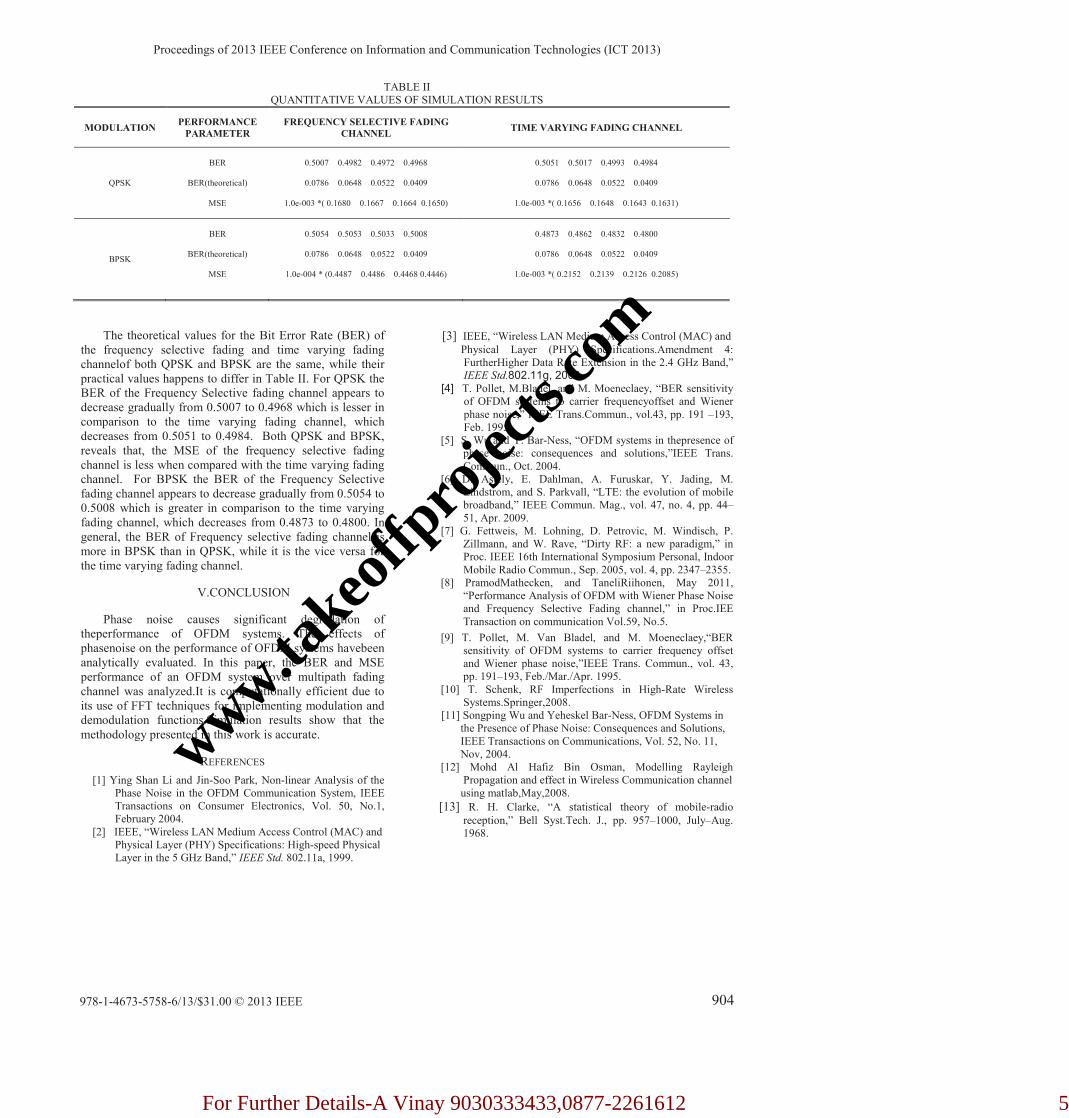
TABLE II QUANTITATIVE VALUES OF SIMULATION RESULTS
MODULATION PERFORMANCE
PARAMETER
FREQUENCY SELECTIVE FADING
CHANNEL TIME VARYING FADING CHANNEL
QPSK
BER
BER(theoretical)
MSE
0.5007 0.4982 0.4972 0.4968
0.0786 0.0648 0.0522 0.0409
1.0e-003 *( 0.1680 0.1667 0.1664 0.1650)
0.5051 0.5017 0.4993 0.4984
0.0786 0.0648 0.0522 0.0409
1.0e-003 *( 0.1656 0.1648 0.1643 0.1631)
BPSK
BER
BER(theoretical)
MSE
0.5054 0.5053 0.5033 0.5008
0.0786 0.0648 0.0522 0.0409
1.0e-004 * (0.4487 0.4486 0.4468 0.4446)
0.4873 0.4862 0.4832 0.4800
0.0786 0.0648 0.0522 0.0409
1.0e-003 *( 0.2152 0.2139 0.2126 0.2085)
The theoretical values for the Bit Error Rate (BER) of
the frequency selective fading and time varying fading
channelof both QPSK and BPSK are the same, while their
practical values happens to differ in Table II. For QPSK the
BER of the Frequency Selective fading channel appears to
decrease gradually from 0.5007 to 0.4968 which is lesser in
comparison to the time varying fading channel, which
decreases from 0.5051 to 0.4984. Both QPSK and BPSK,
reveals that, the MSE of the frequency selective fading
channel is less when compared with the time varying fading
channel. For BPSK the BER of the Frequency Selective
fading channel appears to decrease gradually from 0.5054 to
0.5008 which is greater in comparison to the time varying
fading channel, which decreases from 0.4873 to 0.4800. In
general, the BER of Frequency selective fading channel is
more in BPSK than in QPSK, while it is the vice versa for
the time varying fading channel.
V.CONCLUSION
Phase noise causes significant degradation of
theperformance of OFDM systems. The effects of
phasenoise on the performance of OFDM systems havebeen
analytically evaluated. In this paper, the BER and MSE
performance of an OFDM system over multipath fading
channel was analyzed.It is computationally efficient due to
its use of FFT techniques for implementing modulation and
demodulation functions.Simulation results show that the
methodology presented in this work is accurate.
REFERENCES
[1] Ying Shan Li and Jin-Soo Park, Non-linear Analysis of the
Phase Noise in the OFDM Communication System, IEEE
Transactions on Consumer Electronics, Vol. 50, No.1,
February 2004.
[2] IEEE, “Wireless LAN Medium Access Control (MAC) and
Physical Layer (PHY) Specifications: High-speed Physical
Layer in the 5 GHz Band,” IEEE Std. 802.11a, 1999.
[3] IEEE, “Wireless LAN Medium Access Control (MAC) and
Physical Layer (PHY) Specifications.Amendment 4:
FurtherHigher Data Rate Extension in the 2.4 GHz Band,”
IEEE Std.802.11g, 2003. [4] T. Pollet, M.Bladel, and M. Moeneclaey, “BER sensitivity
of OFDM systems to carrier frequencyoffset and Wiener
phase noise,” IEEE Trans.Commun., vol.43, pp. 191 –193,
Feb. 1995.
[5] S. Wu and Y. Bar-Ness, “OFDM systems in thepresence of
phase noise: consequences and solutions,”IEEE Trans.
Commun., Oct. 2004.
[6] D. Astely, E. Dahlman, A. Furuskar, Y. Jading, M.
Lindstrom, and S. Parkvall, “LTE: the evolution of mobile
broadband,” IEEE Commun. Mag., vol. 47, no. 4, pp. 44–
51, Apr. 2009.
[7] G. Fettweis, M. Lohning, D. Petrovic, M. Windisch, P.
Zillmann, and W. Rave, “Dirty RF: a new paradigm,” in
Proc. IEEE 16th International Symposium Personal, Indoor
Mobile Radio Commun., Sep. 2005, vol. 4, pp. 2347–2355.
[8] PramodMathecken, and TaneliRiihonen, May 2011,
“Performance Analysis of OFDM with Wiener Phase Noise
and Frequency Selective Fading channel,” in Proc.IEE
Transaction on communication Vol.59, No.5.
[9] T. Pollet, M. Van Bladel, and M. Moeneclaey,“BER
sensitivity of OFDM systems to carrier frequency offset
and Wiener phase noise,”IEEE Trans. Commun., vol. 43,
pp. 191–193, Feb./Mar./Apr. 1995.
[10] T. Schenk, RF Imperfections in High-Rate Wireless
Systems.Springer,2008.
[11] Songping Wu and Yeheskel Bar-Ness, OFDM Systems in
the Presence of Phase Noise: Consequences and Solutions,
IEEE Transactions on Communications, Vol. 52, No. 11,
Nov, 2004.
[12] Mohd Al Hafiz Bin Osman, Modelling Rayleigh
Propagation and effect in Wireless Communication channel
using matlab,May,2008.
[13] R. H. Clarke, “A statistical theory of mobile-radio
reception,” Bell Syst.Tech. J., pp. 957–1000, July–Aug.
1968.
Proceedings of 2013 IEEE Conference on Information and Communication Technologies (ICT 2013)
978-1-4673-5758-6/13/$31.00 © 2013 IEEE 904
www.takeo
ffpro
jects.
com
For Further Details-A Vinay 9030333433,0877-2261612 5