13771403-f400-catalogue
TRANSCRIPT

Medium voltage switchgear
F400
Withdrawable circuit breaker1 to 40.5 kV
0
The Guiding System, the new way to create your electrical installations
A comprehensive offer of products with consistent design
The Guiding System is first and foremost a Merlin Gerin product offer covering all electrical distribution needs. However, what makes all the difference is that these products have been designed to operate togheter: mechanical and electrical compatibility, interoperability, modularity, communication.Thus the electrical installation is both optimised and more efficient: better continuity of supply, enhanced safety for people and equipment, guaranteed upgradeability, effective monitoring and control.
Tools to simplify design and implementation
With the Guiding System, you have a comprehensive range of tools - the Guiding Tools - that will help you increase your product knowledge and product utilisation. Of course this is in compliance with current standards and procedures.These tools include technical booklets and guides, design aid software, training courses, etc. and are regularly updated.
For a genuine partnership with you
Because each electrical installation is unique, there is no standard solution. With the Guiding System, the variety of combinations allows for genuine customisation solutions. You can create and implement electrical installations to meet your creative requirements and design knowledge. You and Merlin Gerin’s Guiding System form a genuine partnership.
For more details on the Guiding System,consult www.merlin-gerin.com

0
A consistent design of offers from Medium Voltage to Ultra terminal
All Merlin Gerin offers are designed according to electrical, mechanical and communication consistency rules.The products express this consistency by their overall design and shared ergonomics.
Electrical consistency:
Each product complies with or enhances system performance at co-ordination level: breaking capacity, Isc, temperature rise, etc. for more safety, continuity of supply (discrimination) or economic optimisation (cascading).The leading edge technologies employed in Merlin Gerin’s Guiding System ensure high performance levels in discrimination and cascading of protection devices, electrodynamic withstand of switches and current distributors, heat loss of devices, distribution blocks and enclosures.Likewise, inter-product ElectroMagnetic Compatibilty (EMC) is guaranteed.
Discrimination guarantees co-ordination between the operating characteristics of serial-connected circuit-breakers. Should a fault occurs downstream, only the circuit-breaker placed immediately upstream from the fault will trip.
Mechanical consistency:
Each product adopts dimensional standards simplifying and optimising its use within the system.It shares the same accessories and auxiliaries and complies with global ergonomic choices (utilisation mode, operating mode, setting and configuration devices, tools, etc.) making its installation and operation within the system a simpler process.
Prefabricated and tested solutions, upstream and downstream from the device complying with the IEC 60439-1 switchboard standard.
Communication consistency:
Each product complies with global choices in terms of communication protocols (Modbus, Ethernet, etc.) for simplified integration in the management, supervision and monitoring systems.
Thanks to the use of standard Web technologies, you can offer your customers intelligent Merlin Gerin switchboards allowing easy access to information: follow-up of currents, voltages, powers, consumption history, etc.
Guiding Tools for more efficient design and implementation of your installations.
0
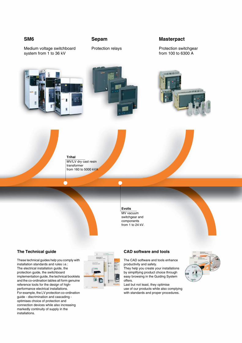
SM6
Medium voltage switchboard system from 1 to 36 kV
Sepam
Protection relays
Masterpact
Protection switchgear from 100 to 6300 A
Trihal
MV/LV dry cast resin transformer from 160 to 5000 kVA
Evolis
MV vacuum switchgear and components from 1 to 24 kV.
The Technical guide
These technical guides help you comply with installation standards and rules i.e.:The electrical installation guide, the protection guide, the switchboard implementation guide, the technical booklets and the co-ordination tables all form genuine reference tools for the design of high-performance electrical installations.For example, the LV protection co-ordination guide - discrimination and cascading - optimises choice of protection and connection devices while also increasing markedly continuity of supply in the installations.
CAD software and tools
The CAD software and tools enhance productivity and safety.They help you create your installations by simplifying product choice through easy browsing in the Guiding System offers.Last but not least, they optimise use of our products while also complying with standards and proper procedures.

0
Compact
Protection switchgear system from 100 to 630 A
Multi 9
Modular protection switchgear system up to 125 A
Prisma Plus
Functional system for electrical distribution switchboards up to 3200 A
Pragma Canalis
Enclosures for distribution switchboards up to 160 A
Prefabricated Busbar Trunking from 25 to 4000 A
PowerLogic
Powermanagement
Training
Training allows you to acquire the Merlin Gerin expertise (installation design, work with power on, etc.) for increased efficiency and a guarantee of improved customer service.The training catalogue includes beginner’s courses in electrical distribution, knowledge of MV and LV switchgear, operation and maintenance of installations, design of LV installations to give but a few examples.
merlin-gerin.com
This international site allows you to access all the Merlin Gerin products in just 2 clicks via comprehensive range data-sheets, with direct links to:
b
complete library: technical documents, catalogs, FAQs, brochures…
b
selection guides from the e-catalog
b
product discovery sites and their Flash animations.You will also find illustrated overviews, news to which you can subscribe, the list of country contacts…
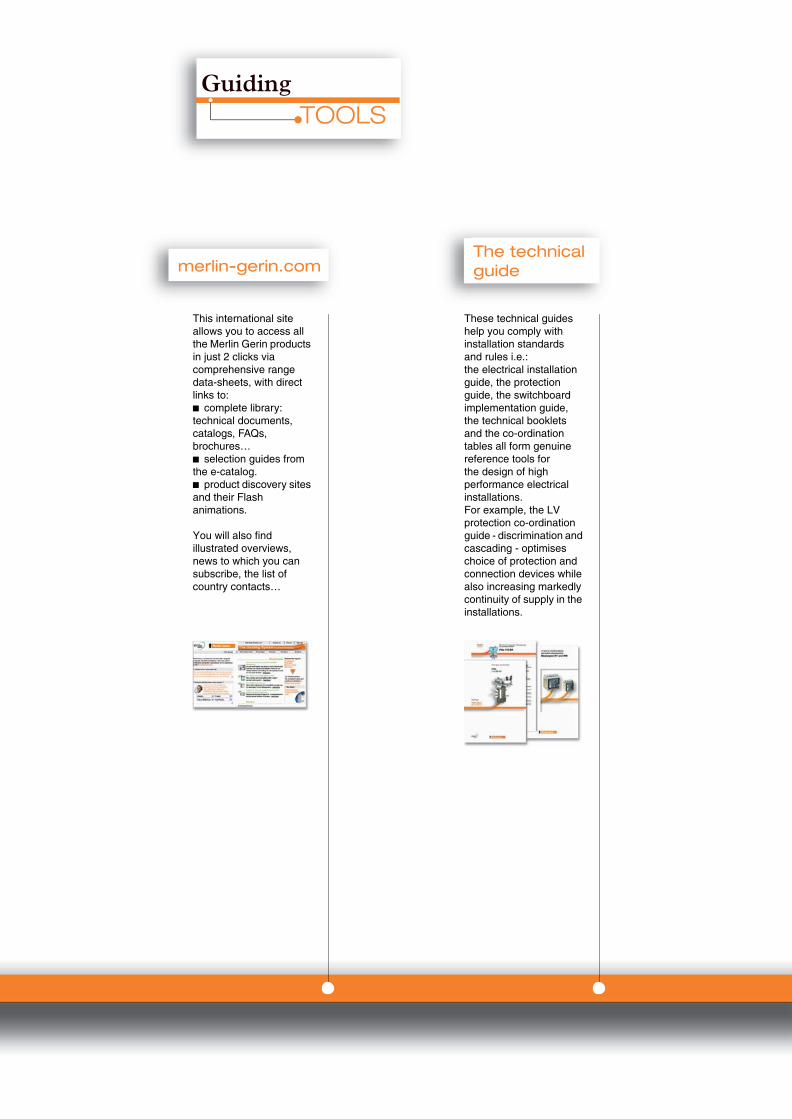
These technical guides help you comply with installation standardsand rules i.e.:the electrical installation guide, the protection guide, the switchboard implementation guide,the technical booklets and the co-ordination tables all form genuine reference tools forthe design of high performance electrical installations.For example, the LV protection co-ordination guide - discrimination and cascading - optimises choice of protection and connection devices while also increasing markedly continuity of supply in the installations.
This international site allows you to access all the Merlin Gerin products in just 2 clicks via comprehensive range data-sheets, with direct links to:
b
complete library: technical documents, catalogs, FAQs, brochures…
b
selection guides from the e-catalog.
b
product discovery sites and their Flash animations.
You will also find illustrated overviews, news to which you can subscribe, the list of country contacts…
1
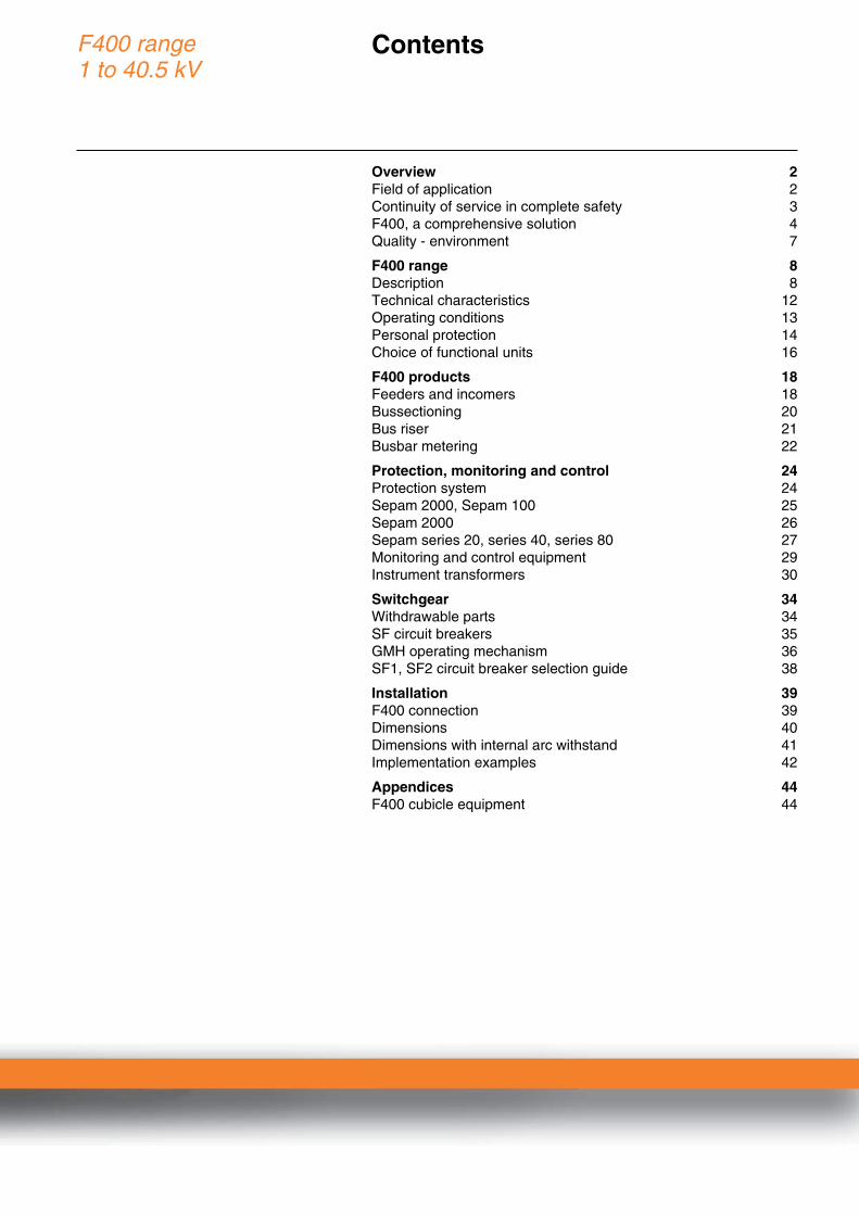
F400 range1 to 40.5 kV
Contents
0
Overview 2
Field of application 2Continuity of service in complete safety 3F400, a comprehensive solution 4Quality - environment 7
F400 range 8
Description 8Technical characteristics 12Operating conditions 13Personal protection 14Choice of functional units 16
F400 products 18
Feeders and incomers 18Bussectioning 20Bus riser 21Busbar metering 22
Protection, monitoring and control 24
Protection system 24Sepam 2000, Sepam 100 25Sepam 2000 26Sepam series 20, series 40, series 80 27Monitoring and control equipment 29Instrument transformers 30
Switchgear 34
Withdrawable parts 34SF circuit breakers 35GMH operating mechanism 36SF1, SF2 circuit breaker selection guide 38
Installation 39
F400 connection 39Dimensions 40Dimensions with internal arc withstand 41Implementation examples 42
Appendices 44
F400 cubicle equipment 44

2
Overview
Field of application
0
F400 is suitable for all electrical power distribution requirements from 1 to 40.5 kV
F400 is metal-enclosed switchgear with withdrawable units designed for indoor installation. F400 is designed for the MV section of HV/MV substations and high-power MV/MV substations.
b
F400 offers:
v
pre-engineered solutions that can be adapted to your specific requirements,
v
significantly reduced maintenance,
v
local support centers throughout the world.
b
F400 gives you the advantages of:
v
continuity of service for your networks,
v
enhanced safety for your staff and operations,
v
optimized investment throughout the life of your installation,
v
the possibility of integrating your medium voltage switchboard into a monitoring and control system.
Applications
PE
5632
8
PE
4031
4
Power distribution
b
Distribution substation,
b
Delivery substation,
b
Secondary transmission substation.
Industry
b
Oil and gas,
b
Chemical industry,
b
Metallurgy,
b
Car industry,
b
Mining,
b
Cement plants, etc.
Infrastructures
b
Airports,
b
Ports,
b
Hospitals,
b
Water treatment, etc.
PE
4031
1P
E40
315
PE
4031
3
PE
4031
2P
E40
313

3
Overview
Continuity of service in complete safety
0
F400 is the result of extensive experience acquired throughout the world. It provides your networks with a high level of availability and safety. F400 integrates a host of innovative solutions designed around proven techniques: high performance switchgear, digital protection, monitoring and control systems, enclosures capable of withstanding internal arcing.
Right from the design stage, F400 has taken three key user requirements into account:
Reliability
b
Each performance level in the F400 range has been type tested.
b
F400 has been designed, manufactured and tested in accordance with the ISO 9001: 2000 quality standard.
b
Three-dimensional computer modeling techniques have been used to study the electrical fields.
Simplicity
b
A user interface that can be understood by all.
b
Interlocks and padlocks to prevent operator errors.
b
Sepam-type protection units for on-site information retrieval without the use of additional devices.
b
Maintenance limited to simple, routine operating checks and cleaning and greasing every 5 to 10 years.
b
Easy to install, as all the cubicles have the same engineering dimensions.
Safety
b
All operations are performed from the front.
b
Racking in or out is only permitted with the door closed.
b
The power-on indicator is located on the front of the functional unit.
b
The earthing switch has making capacity.
b
‘‘Anti-reflex” handles are used for all operations.
b
Internal arc withstand developed for all functional units.
PE
4031
6
PE
4031
7

4
Overview
F400, a comprehensive solution
0
F400 provides the most efficient solutions for controlling and protecting a wide range of applications.Its constituent devices allow F400 to be easily integrated into a monitoring and control system.
Sepam protection relays
Sepam series 20, series 40 and series 80 digital protection relays take full advantage of Merlin Gerin's experience in electrical network protection.Sepam series 20, series 40 and series 80 have all the functions required to provide:
b
effective protection of people and property,
b
accurate measurements and detailed diagnoses,
b
full equipment control,
b
local or remote information and control.
Easy upgradeability
Their modular design allows communication, digital I/O, analog output or temperature acquisition functions to be added.
PowerMeter and Circuit Monitor metering units
One PowerLogic PowerMeter replaces several individual interconnected meters. This cost-effective, high-performance meter provides a full set of accurate true-rms measurements. The PowerLogic series 3000/4000 Circuit Monitor meets the requirements of critical power applications and large energy consumers by providing the information needed to adapt to the changes brought about by deregulation. It is used to measure the average cost of energy used over any length of time or in real time.
Control and monitoring
F400 can easily be integrated into:
b
an existing monitoring and control system: Sepam digital relays or PowerMeter/Circuit Monitor metering unit communicate via a standard protocol (Modbus),
b
a PowerLogic SMS monitoring system.
PE
5517
0
PE
4031
8
PE
4032
4
5
Overview
F400, a comprehensive solution
(continued)
0
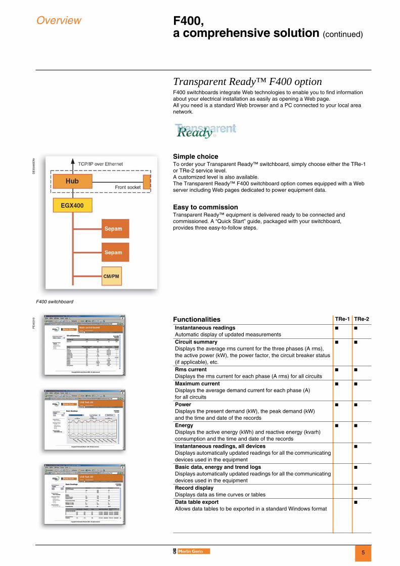
Transparent Ready™ F400 option
F400 switchboards integrate Web technologies to enable you to find information about your electrical installation as easily as opening a Web page.All you need is a standard Web browser and a PC connected to your local area network.
Simple choice
To order your Transparent Ready™ switchboard, simply choose either the TRe-1 or TRe-2 service level. A customized level is also available.The Transparent Ready™ F400 switchboard option comes equipped with a Web server including Web pages dedicated to power equipment data.
Easy to commission
Transparent Ready™ equipment is delivered ready to be connected and commissioned. A “Quick Start” guide, packaged with your switchboard, provides three easy-to-follow steps.
F400 switchboard
DE
5546
5EN
r
PE
4031
9
Functionalities
TRe-1 TRe-2
Instantaneous readings
Automatic display of updated measurements
b b
Circuit summary
Displays the average rms current for the three phases (A rms), the active power (kW), the power factor, the circuit breaker status (if applicable), etc.
b b
Rms current
Displays the rms current for each phase (A rms) for all circuits
b b
Maximum current
Displays the average demand current for each phase (A) for all circuits
b b
Power
Displays the present demand (kW), the peak demand (kW) and the time and date of the records
b b
Energy
Displays the active energy (kWh) and reactive energy (kvarh) consumption and the time and date of the records
b b
Instantaneous readings, all devices
Displays automatically updated readings for all the communicating devices used in the equipment
b
Basic data, energy and trend logs
Displays automatically updated readings for all the communicating devices used in the equipment
b
Record display
Displays data as time curves or tables
b
Data table export
Allows data tables to be exported in a standard Windows format
b

6
Overview
F400, a comprehensive solution
(continued)
0
Schneider Electric Services, by your side throughout the life of your installation
Specifying
We help you to define your solutions: selection guide, technical assistance, advice, etc.
Implementing
We oversee the completion and commissioning of your installation: design, cost optimization, guaranteed performances and dependability, commissioning tests, etc.
Operating
We help run your daily operations in real time: maintenance contract, technical assistance, supply of replacement parts, corrective and preventive maintenance, operation and maintenance training, etc.
Modernizing
We can bring the performance of your installation up to date: installation audit, switchgear diagnosis, adaptation and modification, end of life recycling, etc.
Examples of services provided
Warranty extension
We offer a warranty extension if we check your installation before it is commissioned.
Circuit breaker diagnosisThroughout the life of the equipment, its characteristics can be measured on a regular basis in order to optimize its maintenance.This service may be part of a global installation maintenance contract.
End of life recyclingSchneider Electric Services provides you with an operational system for recycling your medium voltage switchgear.
MT
2006
4 Modernizing
Operating
Specifying
Implementing
MT
2006
5EN
7
Overview Quality - environment 0
Certified quality: ISO 9001A major assetSchneider Electric integrates into each of its units a functional organizational structure the main purpose of which is to check quality and monitor compliance with standards. This procedure is:b uniform throughout all departments,b recognized by many customers and approved organizations.But above all, it is its strict application that has enabled us to obtain the recognition of an independent organization: AFAQ (the French Quality Assurance Association).The quality system used in the design and manufacture of F400 is certified as conforming to the requirements of the ISO 9001: 2000 quality assurance standard.
Strict, systematic checksDuring its manufacture, each F400 undergoes systematic routine tests to check its quality and conformity:b sealing test,b filling pressure test,b measurement of opening and closing speeds,b operating torque measurement,b dielectric test,b safety system and locking tests,b low voltage component tests,b verification of the conformity of drawings and diagrams.The results obtained are recorded and signed on the test certificate for each device by the quality control department.
Environmental conservationAs part of the group’s environmental policy, Schneider Electric Services provides you with an operational system for recovering medium voltage switchgear, which eliminates any discharge into the atmosphere.To help you protect the environment and spare you the task of storing or dismantling the equipment, Schneider Electric Services offers to take back your equipment at the end of its life. F400 has been designed with environmental protection in mind:b the materials used, insulators and conductors are identified and can easily be separated and recycled,b the SF6 can be recovered when the equipment reaches the end of its life and reused after treatment,b production sites are certified to ISO 14000.
MT
2006
6M
T20
069E
N

8
F400 range Description 0
Circuit breakerCurrent transformers (CT)
Cable connection
LV control cabinetRotary voltage
transformers (PT)
Busbar compartment
9
F400 range Description (continued) 0
Description of a functional unitA functional unit comprises all the protective main and auxiliary circuit equipment.Each functional unit combines all the components required to fulfill its function: b the cubicle,b the protection, monitoring and control system,b the withdrawable part.
PE
5632
9
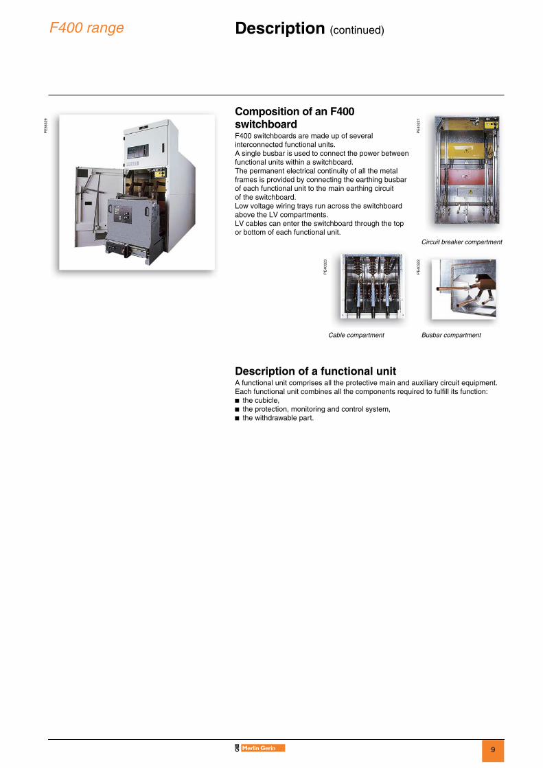
Composition of an F400 switchboardF400 switchboards are made up of several interconnected functional units.A single busbar is used to connect the power between functional units within a switchboard.The permanent electrical continuity of all the metal frames is provided by connecting the earthing busbar of each functional unit to the main earthing circuit of the switchboard.Low voltage wiring trays run across the switchboard above the LV compartments. LV cables can enter the switchboard through the top or bottom of each functional unit.
PE
4032
1
Circuit breaker compartment
PE
4032
3
PE
4032
2
Cable compartment Busbar compartment

10
F400 range Description (continued) 0
The F400 cubicle is type LSC2B (Loss of Service Continuity Category) as defined by IEC 62271-200. This category specifies the possibility of the power being allowed to remain on in one compartment while another compartment is open. The medium voltage parts are separated by metal partitions (PM class) which are earthed.
The F400 cubicle consists of three MV compartments:b the circuit breaker compartment containing the withdrawable part (circuit breaker, disconnector unit or earthing unit),b the busbar compartment,b the cable connection compartment containing the earthing switch, the current sensors and any voltage transformers.
IAC (internal arc classification)The different sides of metal-enclosed switchgear can have different classes of accessibility. The following codification is used to identify these panels (in accordance with IEC 62271-200).A: accessibility restricted to authorized personnel F: access to the front panelL: access to the side panelsR: access to the rear panel
The F400 cubicle is available in 2 versions:b a standard version,b an internal arcing version with IAC-AFLR classification.
The low voltage auxiliaries and the monitoring unit are located in a low voltage control cabinet which is separate from the medium voltage section.Four basic functional units are provided:b incomer or feeder AD6 - RD6b in-line bussectioning CL6 - GL6b busbar metering and earthing TT6b busbar metering LB6The AD and CL cubicles have withdrawable switchgear.
DE
5672
4
F400 cubicle with IAC-AFLR internal arcing
Cable compartment LV control cabinet
Busbar compartment Circuit breaker compartment

11
F400 range Description (continued) 0
Protection, monitoring and control systemThis system includes the following equipment:b Sepam protection, monitoring and control unit,b Current sensors, which may be of 3 types:v functional current transformers,v DIN format current transformers,v low voltage toroid type current transformers.b Voltage transformers:v withdrawable fused voltage transformers,v fixed voltage transformers.b CSH type homopolar toroids.
Withdrawable partThe withdrawable part includes:b The circuit breaker or the earthing unit with its closing and opening mechanism, or the disconnector unit,b The racking in/out handle propulsion mechanism, interlocks for fixing the withdrawable part firmly to the fixed part in the operating or disconnected position.
Surface treatmentb All the metal surfaces of the switchboard are treated to protect them from corrosion.b The metal is manufactured in accordance with a galvanization process defined by ISO 3575.b The metal front panels are electrogalvanized with an epoxy polyester coating, standard color RAL 9002 and their surface has been tested in accordance with ISO 6272.
12
F400 range Technical characteristics 0P
E40
329
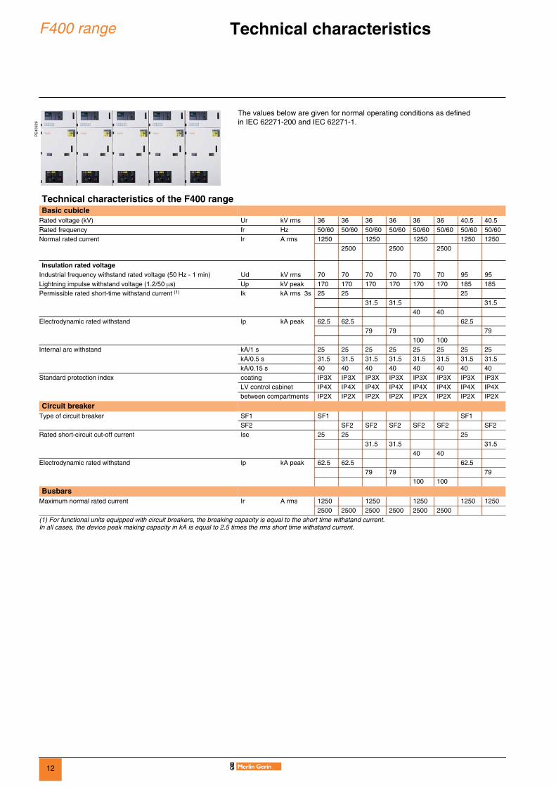
The values below are given for normal operating conditions as defined in IEC 62271-200 and IEC 62271-1.
Technical characteristics of the F400 rangeBasic cubicle
Rated voltage (kV) Ur kV rms 36 36 36 36 36 36 40.5 40.5Rated frequency fr Hz 50/60 50/60 50/60 50/60 50/60 50/60 50/60 50/60Normal rated current Ir A rms 1250 1250 1250 1250 1250
2500 2500 2500
Insulation rated voltageIndustrial frequency withstand rated voltage (50 Hz - 1 min) Ud kV rms 70 70 70 70 70 70 95 95Lightning impulse withstand voltage (1.2/50 µs) Up kV peak 170 170 170 170 170 170 185 185Permissible rated short-time withstand current (1) Ik kA rms 3s 25 25 25
31.5 31.5 31.540 40
Electrodynamic rated withstand Ip kA peak 62.5 62.5 62.579 79 79
100 100Internal arc withstand kA/1 s 25 25 25 25 25 25 25 25
kA/0.5 s 31.5 31.5 31.5 31.5 31.5 31.5 31.5 31.5kA/0.15 s 40 40 40 40 40 40 40 40
Standard protection index coating IP3X IP3X IP3X IP3X IP3X IP3X IP3X IP3XLV control cabinet IP4X IP4X IP4X IP4X IP4X IP4X IP4X IP4Xbetween compartments IP2X IP2X IP2X IP2X IP2X IP2X IP2X IP2X
Circuit breakerType of circuit breaker SF1 SF1 SF1
SF2 SF2 SF2 SF2 SF2 SF2 SF2Rated short-circuit cut-off current Isc 25 25 25
31.5 31.5 31.540 40
Electrodynamic rated withstand Ip kA peak 62.5 62.5 62.579 79 79
100 100
BusbarsMaximum normal rated current Ir A rms 1250 1250 1250 1250 1250
2500 2500 2500 2500 2500 2500(1) For functional units equipped with circuit breakers, the breaking capacity is equal to the short time withstand current. In all cases, the device peak making capacity in kA is equal to 2.5 times the rms short time withstand current.

13
F400 range Operating conditions 0
Working conditions
Normal working conditions in accordance with IEC 62271-1 for indoor switchgear b Ambient air temperature: v less than or equal to 40°C,v less than or equal to 35°C on average over 24 hours,v greater than or equal to –5°C.b Altitude: v less than or equal to 1000 m,v above 1000 m, a derating coefficient will be applied (please consult us).b Atmosphere: v little or no dust, smoke, salt, corrosive or flammable gas and vapor (clean industrial air).b Humidity: v average relative humidity over 24 hours y 95%, v average relative humidity over 1 month y 90%, v average vapor pressure over 24 hours y 2.2 kPa, v average vapor pressure over 1 month y 1.8 kPa.
Specific operating conditions (consult us)F400 has been developed to meet the following specific conditions:b temperature (possible derating),b altitudes (possible derating).
Storage conditionsIn order to retain all the qualities of a functional unit during prolonged storage, we recommend that the equipment is kept in its original packaging, in a dry place sheltered from the sun and rain at a temperature between – 25°C and + 55°C.
StandardsThe F400 range conforms to the following IEC international standards:b IEC 62271-1: common clauses for high-voltage switchgear,b IEC 62271-200: AC metal-enclosed switchgear for rated voltages between 1 and 52 kV,b IEC 62271-100: high-voltage alternating current circuit-breakers,b IEC 60282-2: high-voltage fuses,b IEC 62271-102: alternating current disconnectors and earthing switches,b IEC 60255: measuring relays and protection equipment,b IEC 60044-1: current transformers,b IEC 60044-2: voltage transformers.
MT
2007
2

14
F400 range Personal protection 0
F400 internal arcing (in conformance withIEC 62271-200)
Annex A of IEC 62271-200 defines the “method for testing the metal-enclosed switchgear under conditions of arcing due to an internal fault”.The F400 cubicle conforms to this standard and has successfully passed all the type tests specified by this standard. The F400 cubicle is therefore designed to provide the highest possible degree of protection for operators in the vicinity of the equipment in the event of an internal fault.
The F400 internal arc protection is AFLR type (all four sides of the cubicle are protected) in order to protect operators when they go behind the cubicle. The F400 switchboard is installed in a room with a minimum height of 4 m.F400 is designed to eliminate the effects of internal arcing safely, by:b locating metal flaps above the enclosure to limit overpressure in the compartments in the event of an internal fault,b using nonflammable materials for the cubicle,v F400 can be fitted with an optional system to detect internal arcing and disconnect the power supply in order to limit the duration of the fault current to less than 140 ms.
Switchboard operationsThe switchboards are installed, operated and maintained from the front panel. Certain installation and maintenance operations are performed from the rear of the cubicle:b installation of medium voltage cables,b operation of voltage transformers (PT).

15
F400 range Personal protection (continued) 0
Dependable mechanical control devicesThe switchboards are operated from the front panel. The operator is guided by means of pictograms on each front panel, which make it very easy to understand the sequence of operations and the status of the devices.Interlocks and padlocks prevent operator error. The operator is protected by several additional security levels:b Racking in or out is only permitted with the door closed.b The comprehensive set of mechanical and electrical interlocks prevent operator error. Keylocks or padlocks can be added, depending on the specific operating procedures required.Each selector can be fitted with one to three padlocks.b All operations are performed from the front panel.b The power-on indicator is located on the front panel of the functional unit, in the immediate vicinity of the earthing switch control.
Optionsb Circuit breaker disabling during extraction. This function enables the circuit breaker control springs to be disabled during the extraction process. b Rack-in inhibition. This function prevents the withdrawable part from being racked in.
PE
4032
6
Earthing switch control
4-position selectorb extractionb testb rack-inb in operation
Rack-in inhibition
Voltage indicators(VPIS)
Keylock
Earthing switch position indicator
Open pushbutton
Circuit breaker control
Rack-in/out
Rack-in/out indicator
16
F400 range Choice of functional units 0
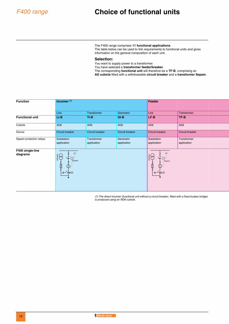
The F400 range comprises 11 functional applications.The table below can be used to link requirements to functional units and gives information on the general composition of each unit.
Selection:You want to supply power to a transformer.You have selected a transformer feeder/breaker.The corresponding functional unit will therefore be a TF-B, comprising an AD cubicle fitted with a withdrawable circuit breaker and a transformer Sepam.
(1) The direct incomer (functional unit without a circuit breaker, fitted with a fixed busbar bridge) is produced using an RD6 cubicle.
Function Incomer (1) Feeder
Line Transformer Generator Line Transformer
Functional unit LI-B TI-B GI-B LF-B TF-B
Cubicle AD6 AD6 AD6 AD6 AD6
Device Circuit breaker Circuit breaker Circuit breaker Circuit breaker Circuit breaker
Sepam protection relays Substation Transformer Generator Substation Transformerapplication application application application application
F400 single-line diagrams
MT
2008
0
MT
2008
1
Sepam
17
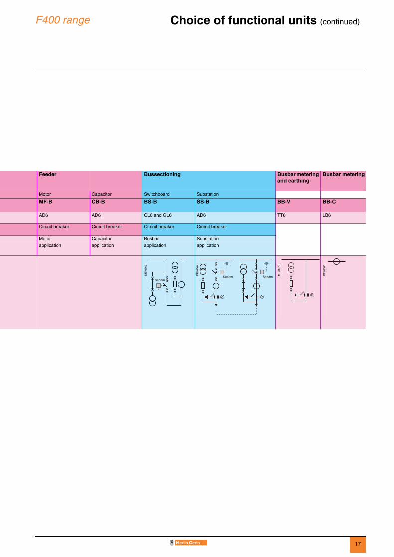
F400 range Choice of functional units (continued) 0
Feeder Bussectioning Busbar metering and earthing
Busbar metering
Motor Capacitor Switchboard Substation
MF-B CB-B BS-B SS-B BB-V BB-C
AD6 AD6 CL6 and GL6 AD6 TT6 LB6
Circuit breaker Circuit breaker Circuit breaker Circuit breaker
Motor Capacitor Busbar Substationapplication application application application
DE
4036
2
DE
4036
4
MT
2007
8
DE
4036
3

18
F400 products Feeders and incomers 0
AD6
Functionsbbbb Cubiclev standard LSC2B PM,v IAC AFLR LSC2B PM (option).
bbbb LV control cabinet
bbbb Withdrawable partv SF1 and SF2 1250 A circuit breakers,v SF2 2500 A circuit breaker,v disconnector unit.
bbbb Voltage transformers (phase/earth)v withdrawable with fuses,v fixed.
bbbb Earthing switchv making capacity.
bbbb Voltage indicatorv VPIS.
bbbb Cable connection (from the bottom, rear access)v single-pole (1 to 4 cables),v three-pole (1 to 4 cables).
bbbb Current transformers
bbbb Anti-condensation heating element
bbbb Lightning arrester (option)
bbbb Incomer from the top (adaptation)v cables,v busbars.
DE
5673
0
DE
5673
1
No. of windings Functional CTs Conventional DIN format CT
LV toroid type CT
3 maximum buuuu 3 b b
b bb
19
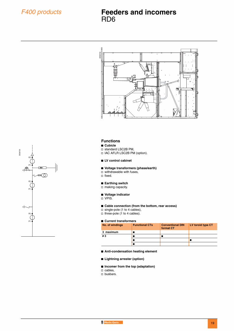
F400 products Feeders and incomers 0
RD6
Functionsbbbb Cubiclev standard LSC2B PM,v IAC AFLR LSC2B PM (option).
bbbb LV control cabinet
bbbb Voltage transformers (phase/earth)v withdrawable with fuses,v fixed.
bbbb Earthing switchv making capacity.
bbbb Voltage indicatorv VPIS.
bbbb Cable connection (from the bottom, rear access)v single-pole (1 to 4 cables),v three-pole (1 to 4 cables).
bbbb Current transformers
bbbb Anti-condensation heating element
bbbb Lightning arrester (option)
bbbb Incomer from the top (adaptation)v cables,v busbars.
DE
5673
2
DE
5673
3
No. of windings Functional CTs Conventional DIN format CT
LV toroid type CT
3 maximum buuuu 3 b b
b bb
20
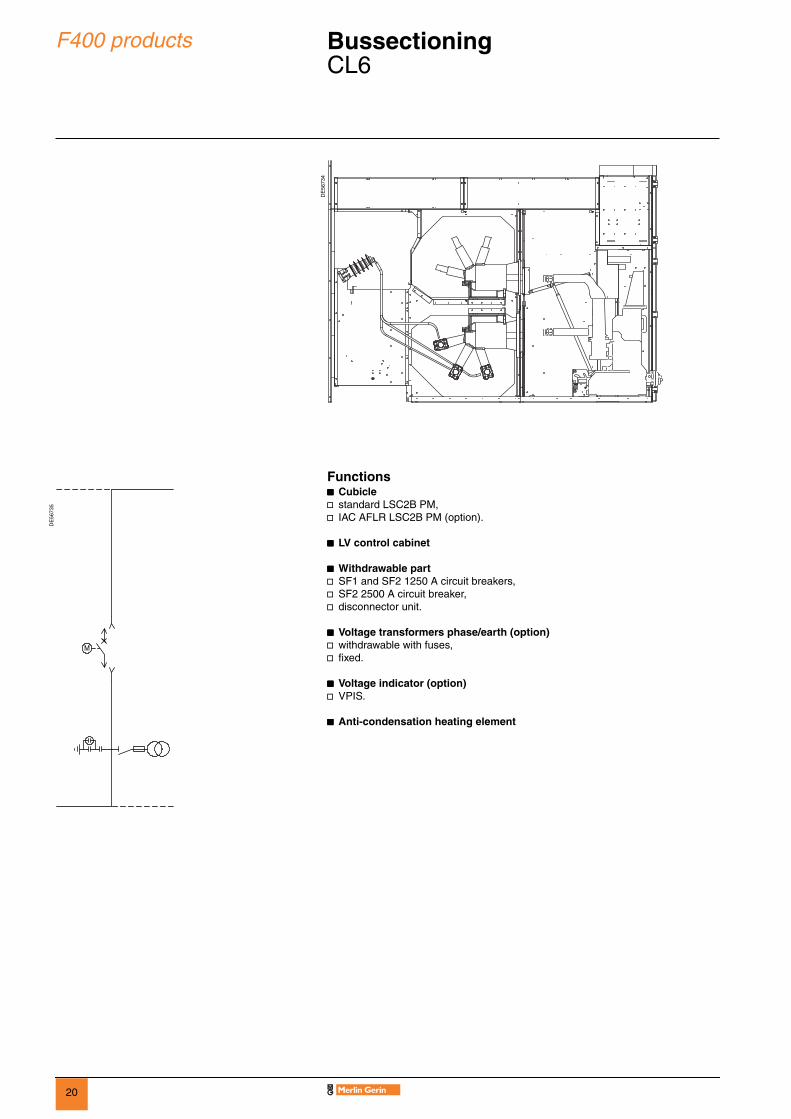
F400 products Bussectioning 0
CL6
Functionsbbbb Cubiclev standard LSC2B PM,v IAC AFLR LSC2B PM (option).
bbbb LV control cabinet
bbbb Withdrawable partv SF1 and SF2 1250 A circuit breakers,v SF2 2500 A circuit breaker,v disconnector unit.
bbbb Voltage transformers phase/earth (option)v withdrawable with fuses,v fixed.
bbbb Voltage indicator (option)v VPIS.
bbbb Anti-condensation heating element
DE
5673
4
DE
5673
5
21
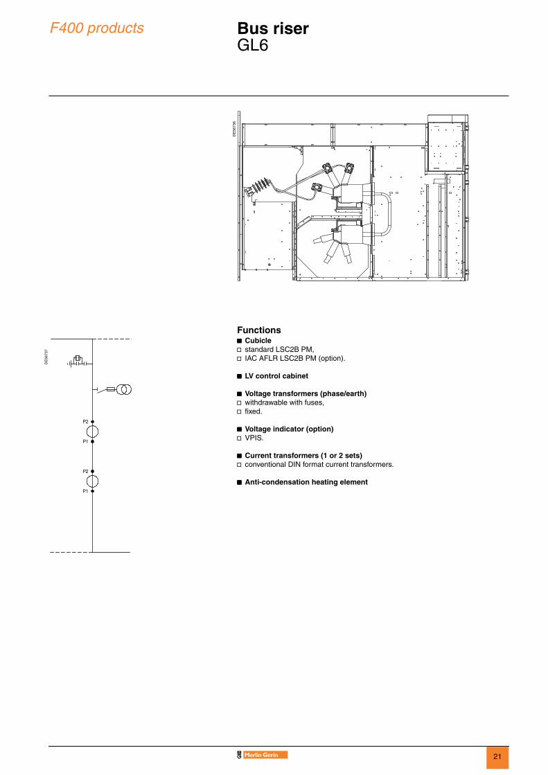
F400 products Bus riser 0
GL6
Functionsbbbb Cubiclev standard LSC2B PM,v IAC AFLR LSC2B PM (option).
bbbb LV control cabinet
bbbb Voltage transformers (phase/earth)v withdrawable with fuses,v fixed.
bbbb Voltage indicator (option)v VPIS.
bbbb Current transformers (1 or 2 sets)v conventional DIN format current transformers.
bbbb Anti-condensation heating element
DE
5673
6
DE
5673
7
22
F400 products Busbar metering 0
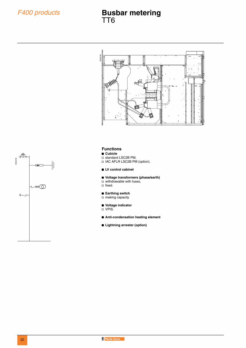
TT6
Functionsbbbb Cubiclev standard LSC2B PM,v IAC AFLR LSC2B PM (option).
bbbb LV control cabinet
bbbb Voltage transformers (phase/earth)v withdrawable with fuses,v fixed.
bbbb Earthing switchv making capacity.
bbbb Voltage indicatorv VPIS.
bbbb Anti-condensation heating element
bbbb Lightning arrester (option)
DE
5673
8
DE
5673
9
23
F400 products Busbar metering 0
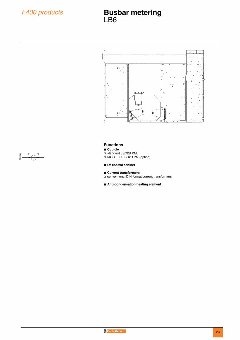
LB6
Functionsbbbb Cubiclev standard LSC2B PM,v IAC AFLR LSC2B PM (option).
bbbb LV control cabinet
bbbb Current transformersv conventional DIN format current transformers.
bbbb Anti-condensation heating element
DE
5674
0
DE
5674
1

24
Protection, monitoring and control
Protection system 0
Sepam range
Sepam: digital protection relaysSepam is a range of digital protection relays central to the protection, monitoring and control system of the F400 functional unit: all the necessary protection, metering, control, monitoring and indication functions are performed by Sepam.
Like the F400 range, the Sepam range of relays is designed to provide the optimum solution for each application; it includes:b Sepam S, for the protection of substation incomers and feeders,b Sepam B, for the protection of busbars,b Sepam T, for the protection of transformers,b Sepam M, for the protection of motors,b Sepam G, for the protection of generators,b Sepam C, for the protection of capacitors.
The Sepam range consists of:b Sepam series 20, series 40 and series 80, a range of modular protection relays to meet your specific needs,b Sepam 2000, a range of performance-focused protection relays.
Advantages of Sepam
Reliabilityb Over 20 years of experience in multi-function digital relays for the protection of medium-voltage electrical networks.b Cumulative experience of more than 150,000 Sepam protection relays in use in over 90 countries.
Qualityb Design quality based on dependability objectives and a thorough analysis of environmental constraints: temperature, pollution, EMC, dielectric strength, etc. b Manufacturing quality based on procurement agreements with suppliers and quality control at all stages of the manufacturing phases.
Easy to useb Local operation facilitated by the ergonomic man-machine interface (MMI) providing users with clear, comprehensive information in their own language.b Easy to set up with the flexible user-friendly configuration software.
Each F400 functional unit is fitted with a protection, monitoring and control system consisting of:b instrument transformers to measure the required electrical values (phase current, residual current, voltages, etc.),b protection relays, with functions appropriate for the part of the network to be protected,b metering equipment, to provide information to operators,b low voltage relays to control, amongst other things, the breaking device (circuit breaker) of the withdrawable part,b various auxiliaries: secondary circuit test units, etc.
DE
5671
0
Metering equipment protection relay
Switchgear (circuit breaker)
Voltage transformer
Current transformer
LPCT or LV toroid current transformer (please consult us)
PE
5517
0

25
Protection, monitoring and control
Sepam 2000Sepam 100
Sepam 2000, for all applicationsThe Sepam 2000 range of digital protection units provides comprehensive solutions for all applications: substations, busbars, transformers and motors, generators and capacitors.Different types of Sepam 2000 are provided for each type of equipment to be protected.For example, there are more than 30 different types of dedicated Sepam 2000 for protecting transformers.Each Sepam 2000 is an optimized solution designed to meet the actual requirements of a functional application as closely as possible and including all the necessary, ready-to-use functions.
The performance-focused, Sepam 2000 includes the following functions:b measurement functions: measurement of currents and voltages, measurement of power and active and reactive energy, etc.b protection functions: directional phase and earthing protection,b differential transformer or machine protection, etc.b monitoring and control functions: Sepam 2000 is a real programmable logical controller which is pre-programmed to perform standard monitoring and control functions and which can be reprogrammed to handle any specific automated control function.
To choose the type of Sepam 2000 best suited to your application, see “Sepam 2000 product range” (ref. AC0401) which contains:b comprehensive selection charts to enable you to choose the right Sepam for your application,b Sepam characteristics.
Additional Sepam 100 modulesSepam 100 modules complete the Sepam range and can be installed separately or combined with a Sepam protection relay, Sepam 2000, Sepam series 20, 40 or 80.
There are several types of Sepam 100:b Sepam 100 MI, breaking device local control and indication modules (various block diagrams are available),b Sepam 100 LD, high impedance differential protection,b Sepam 100 LA, self-powered protection (back-up protection without auxiliary power supply).
MT
2009
7
Sepam 2000
E61
780
PE
6011
6
PE
6011
7
PE
6011
8
Sepam 100MI Sepam 100LD Sepam 100LA

26
Protection, monitoring and control
0Sepam 2000Selection guide
Functions Sepam 2000Functional units SS-B, BS-B, LF-B, LI-B TI-B, TF-B MF-B GI-B CB-BApplications Substation Busbar Transfo. Motor Generator Capacitor
MeasurementsCurrent I1/I2/I3/I0
IM1/IM2/IM3Itrip 1/2/3/0
b b b b b b
Voltages and frequencies U21/U32/U13V1,V2,V3V0Vdf
b b b b b b
Powers and energies P/Q, PM/QM, cos ϕEa/Er
b b b b b b
tTemperatures b b bProtection ANSI codes
Phase 50/51 b b b b b bEarth 50N/51N b b b b b bImbalance 46 b bDirectional 67/67N b b 67N bDifferential 87T/87M/87B 87T 87M 87MRestricted earthing differential 64REF b bOverload 49/49T/38 b b b 49Motor 37/48/51LR/66 bVoltage 59/27
59Nb b b b 27/59
Frequency 81H/81L b b bDecoupling (df/dt) 81R b bSpecific 32P
7927R
2527D
50N/51(neutral point)50/51 (tank earth)27R
32P and 32Q/4027D/47
32P, 32Q/402550V/51V
step imbalance
Network diagnosisOscillography 2 recordings of 86 periodsSwitchgear diagnosis
Operating timeTrip currents, sum of breaking currents A2 b b b b b bTrip circuit monitoring b b b b b bWatchdog 1 output/4 contacts: 2 x (1NC + 1NO)Communication
Protocol ModbusInterface RS485, 2 or 4 wiresControl and monitoring
Inputs/outputs basic 10I/6O On/Offmaximum 26I/14O On/Off
Breaking device control b b b b b bLogical selectivity b b b b b bCustomization parameter setting b b b b b b
programming b b b b b b
b Standard functions
27
Protection, monitoring and control
0Sepam series 20, series 40, series 80
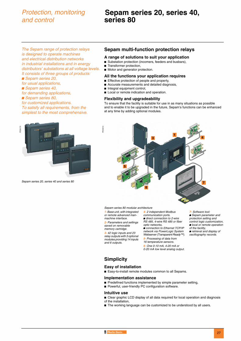
The Sepam range of protection relays is designed to operate machines and electrical distribution networks in industrial installations and in energy distributors’ substations at all voltage levels.It consists of three groups of products: b Sepam series 20, for usual applications,b Sepam series 40,for demanding applications,b Sepam series 80, for customized applications.To satisfy all requirements, from the simplest to the most comprehensive.
Sepam multi-function protection relays
A range of solutions to suit your applicationb Substation protection (incomers, feeders and busbars),b Transformer protection,b Motor and generator protection.
All the functions your application requires b Effective protection of people and property,b Accurate measurements and detailed diagnosis,b Integral equipment control,b Local or remote indication and operation.
Flexibility and upgradeabilityTo ensure that the facility is suitable for use in as many situations as possible and to enable it to be upgraded in the future, Sepam’s functions can be enhanced at any time by adding optional modules.
PE
5517
0
PE
4001
3
Sepam series 20, series 40 and series 80
Sepam series 80 modular architecture1- Base unit, with integrated or remote advanced man-machine interface.2- Parameters and settings saved on removable memory cartridge.3- 42 logic inputs and 23 relay outputs with 3 optional modules providing 14 inputs and 6 outputs.
4- 2 independent Modbus communication ports.b direct connection to 2-wire RS 485, 4-wire RS 485 or fiber optic networks,b connection to Ethernet TCP/IP network via PowerLogic System Webserver (Transparent Ready™).5- Processing of data from 16 temperature sensors.6- One 0-10 mA, 4-20 mA or 0-20 mA low level analog output.
7- Software tool:b Sepam parameter and protection setting and control logic customization,b local or remote operation of the facility,b retrieval and display of oscillography records.
Simplicity
Easy of installation b Easy-to-install remote modules common to all Sepams.
Implementation assistanceb Predefined functions implemented by simple parameter setting,b Powerful, user-friendly PC configuration software.
Intuitive useb Clear graphic LCD display of all data required for local operation and diagnosis of the installation,b The working language can be customized to be understood by all users.
31
5
67
4

28
Protection, monitoring and control
0Sepam series 20, series 40, series 80Selection guide
Sepam Protection Functional units and applicationsBasic Specific SS-B, BS-B, LF-B,
LI-BTI-B, TF-B
MF-B GI-B
Substation Busbar Transfo. Motor Generator
Sepam series 20b 10 logic inputsb 8 relay outputsb 8 temperature sensor inputsb 1 Modbus communication port
DE
5671
1
Current protection
S20 T20 M20
DE
5671
2
Voltage and frequency protection
B21
Frequency- derived
B22
Sepam series 40b 10 logic inputsb 8 relay outputsb 16 temperature sensor inputsb 1 Modbus communication portb logic equations editor
DE
5671
3
Current, voltage and frequency protection
S40 T40 G40
Directional earth
S41 M41
Directional earth and phase
S42 T42
Sepam series 80b 42 logic inputsb 23 relay outputsb 16 temperature sensor inputsb 2 Modbus communication portsb logic equations editor
DE
5671
4
Current, voltage and frequency protection
S80
Directional earth
S81 T81 M81
DE
5671
5
Directional earth and phase
S82 T82 G82
Transformer of group assembly differential
T87 M88 G88
MachineDifferential
M87 G87
29
Protection, monitoring and control
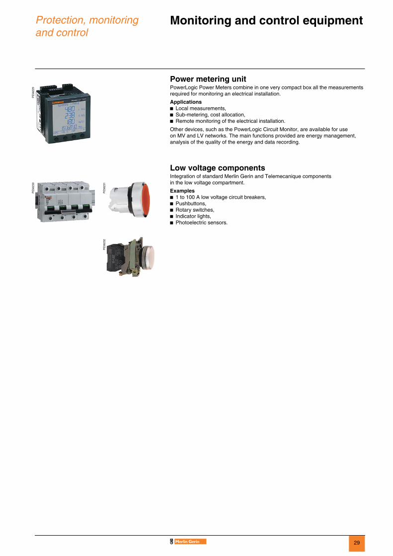
Monitoring and control equipment 0
Power metering unitPowerLogic Power Meters combine in one very compact box all the measurements required for monitoring an electrical installation.
Applicationsb Local measurements,b Sub-metering, cost allocation,b Remote monitoring of the electrical installation.
Other devices, such as the PowerLogic Circuit Monitor, are available for use on MV and LV networks. The main functions provided are energy management, analysis of the quality of the energy and data recording.
Low voltage componentsIntegration of standard Merlin Gerin and Telemecanique components in the low voltage compartment.
Examplesb 1 to 100 A low voltage circuit breakers,b Pushbuttons,b Rotary switches,b Indicator lights,b Photoelectric sensors.
PE
5622
9P
E56
230
PE
5623
1P
E56
232

30
Protection, monitoring and control
Instrument transformers 0
Conventional current transformers are used to provide power to measuring, metering or monitoring devices. They measure primary currents from 50 A to 2500 A.
Schneider Electric has drawn up a list of preferred current transformers which are appropriate for use with digital protection devices to make it easier to determine accuracy characteristics.
The live parts of the dry-insulated current transformers are integrated into a resin enclosure. These compact transformers have excellent electrical and mechanical characteristics and are fully protected against fire hazards.
Conventional current transformers provide power to the “current” circuits of the measuring instruments and/or protection devices.
Functional current transformersF400 cubicles are fitted with functional current transformers.These transformers are integrated into the power bushings on which the fixed rack-in contacts are mounted.The current transformers have one, two or three 1 or 5 A secondary windings (1). The transformation ratios can be changed in the LV control cabinet.
Technical characteristics
(1) For all other characteristics, please contact us.
PE
5503
2
Functional current transformer
Type Ratio (A/A) Measurement VA cl 0.5
Protection VA 5P20
Ith max
25 kA/1 s 25 kA/3 s 31.5 kA/1 s 31.5 kA/3 s 40 kA/1 s 40 kA/3 s
TCF4/N2 50-100/5-5 10-20 5-10 b b b b b100-200/5-5 15-30 5-10 b b b b b200-400/5-5 15-30 5-10 b b b b b300-600/5-5 15-30 5-10 b b b b b b400-800/5-5 15-30 5-10 b b b b b b600-1200/5-5 15-30 5-10 b b b b b b
TCF4G/N2 1500/5-5 15 5 b b b b b b2000/5-5 15 5 b b b b b b2500/5-5 15 5 b b b b b b

31
Protection, monitoring and control
Instrument transformers (continued) 0
DIN format current transformersF400 cubicles are fitted with DIN format current transformers when the installation requires additional secondary windings (>3).The current transformers have one, two or three 1 to 5 A secondary windings (1).The transformation ratios can be changed in the LV control cabinet.
Technical characteristics
(1) For all other characteristics, please contact us.
LV toroid type current transformersF400 cubicles can be fitted with low voltage toroid type current transformers.F400 cubicles are fitted with LV toroid type current transformers when the installation requires additional secondary windings (>3).AOPC, ARL4 and ARL5 toroid current transformers are installed in the cable compartment. The toroid accepts the secondary windings; the cable is the primary winding.The transformers have a primary current of 50 to 2500 A and a secondary current of 1 to 5 A.The type of AOPC, ARL4 and ARL5 current transformer selected depends on the number of medium voltage cables installed in the F400 cubicle.
(2) Cable section for size 3 connection pads: 150 to 630 mm2.
CSH type homopolar toroidCSH 120 and CSH 200 homopolar toroids provide more sensitive protection by measuring earth fault currents directly.They are specifically designed for the Sepam range and can be connected directly to the “residual current” of the Sepam devices.They differ only in their diameter: b CSH 120 - internal diameter 120 mm,b CSH 200 - internal diameter 200 mm.
PE
5020
6
DIN format current transformer
Type Ratio (A/A) Measurement VA cl 0.5
Protection VA 5P20
Ith max
25 kA/1 s 25 kA/3 s 31.5 kA/1 s 31.5 kA/3 s 40 kA/1 s 40 kA/3 s
ARM9T/N2 50-100/5-5 10-20 5-10 b b b b b100-200/5-5 15-30 5-10 b b b b b200-400/5-5 15-30 5-10 b b b b b300-600/5-5 15-30 5-10 b b b b b b400-800/5-5 15-30 5-10 b b b b b b600-1200/5-5 15-30 5-10 b b b b b b1500/5-5 15 5 b b b b b b2000/5-5 15 5 b b b b b b2500/5-5 15 5 b b b b b b
PE
4032
5
ARL4 current transformer
Type of connection pads (for reference only)Rated voltage Rated current Short-circuit
currentMax. number of cables
by phase(2)
Max. number of CTs
by phasekV A kA size and type12-36 1250/1600 31.5 2 2 x AOPC12-36 2000 31.5 3 2 x ARL412-36 2500 31.5 4 2 x ARL5
E28
678
CSH homopolar toroid
32
Protection, monitoring and control
Instrument transformers (continued) 0
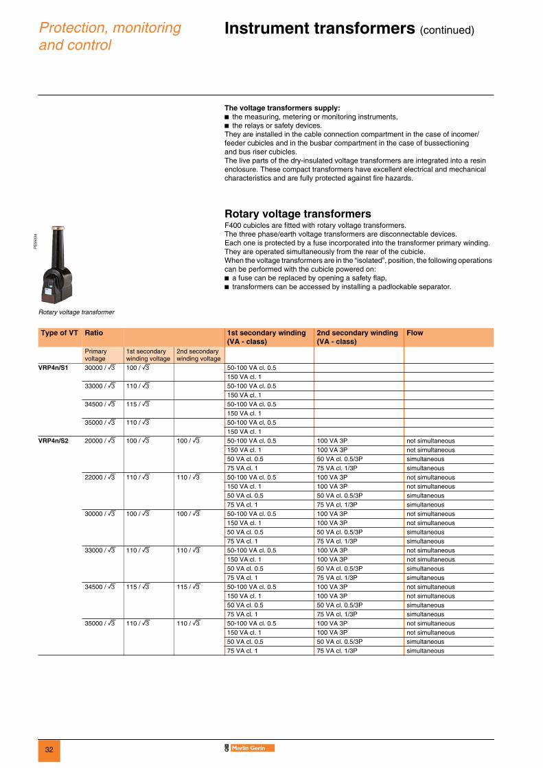
The voltage transformers supply:b the measuring, metering or monitoring instruments,b the relays or safety devices.They are installed in the cable connection compartment in the case of incomer/feeder cubicles and in the busbar compartment in the case of bussectioning and bus riser cubicles.The live parts of the dry-insulated voltage transformers are integrated into a resin enclosure. These compact transformers have excellent electrical and mechanical characteristics and are fully protected against fire hazards.
Rotary voltage transformersF400 cubicles are fitted with rotary voltage transformers.The three phase/earth voltage transformers are disconnectable devices.Each one is protected by a fuse incorporated into the transformer primary winding.They are operated simultaneously from the rear of the cubicle.When the voltage transformers are in the “isolated”, position, the following operations can be performed with the cubicle powered on:b a fuse can be replaced by opening a safety flap,b transformers can be accessed by installing a padlockable separator.
PE
5503
4
Rotary voltage transformer
Type of VT Ratio 1st secondary winding(VA - class)
2nd secondary winding(VA - class)
Flow
Primary voltage
1st secondary winding voltage
2nd secondary winding voltage
VRP4n/S1 30000 / 3 100 / 3 50-100 VA cl. 0.5150 VA cl. 1
33000 / 3 110 / 3 50-100 VA cl. 0.5150 VA cl. 1
34500 / 3 115 / 3 50-100 VA cl. 0.5150 VA cl. 1
35000 / 3 110 / 3 50-100 VA cl. 0.5150 VA cl. 1
VRP4n/S2 20000 / 3 100 / 3 100 / 3 50-100 VA cl. 0.5 100 VA 3P not simultaneous150 VA cl. 1 100 VA 3P not simultaneous50 VA cl. 0.5 50 VA cl. 0.5/3P simultaneous75 VA cl. 1 75 VA cl. 1/3P simultaneous
22000 / 3 110 / 3 110 / 3 50-100 VA cl. 0.5 100 VA 3P not simultaneous150 VA cl. 1 100 VA 3P not simultaneous50 VA cl. 0.5 50 VA cl. 0.5/3P simultaneous75 VA cl. 1 75 VA cl. 1/3P simultaneous
30000 / 3 100 / 3 100 / 3 50-100 VA cl. 0.5 100 VA 3P not simultaneous150 VA cl. 1 100 VA 3P not simultaneous50 VA cl. 0.5 50 VA cl. 0.5/3P simultaneous75 VA cl. 1 75 VA cl. 1/3P simultaneous
33000 / 3 110 / 3 110 / 3 50-100 VA cl. 0.5 100 VA 3P not simultaneous150 VA cl. 1 100 VA 3P not simultaneous50 VA cl. 0.5 50 VA cl. 0.5/3P simultaneous75 VA cl. 1 75 VA cl. 1/3P simultaneous
34500 / 3 115 / 3 115 / 3 50-100 VA cl. 0.5 100 VA 3P not simultaneous150 VA cl. 1 100 VA 3P not simultaneous50 VA cl. 0.5 50 VA cl. 0.5/3P simultaneous75 VA cl. 1 75 VA cl. 1/3P simultaneous
35000 / 3 110 / 3 110 / 3 50-100 VA cl. 0.5 100 VA 3P not simultaneous150 VA cl. 1 100 VA 3P not simultaneous50 VA cl. 0.5 50 VA cl. 0.5/3P simultaneous75 VA cl. 1 75 VA cl. 1/3P simultaneous

33
Protection, monitoring and control
Instrument transformers (continued) 0
Fixed voltage transformersF400 cubicles can be fitted with fixed voltage transformers.The three transformers are phase/earth type voltage transformers.
PE
5632
7
Fixed voltage transformer
Type of VT Ratio Ratio Ratio 1st secondary winding(VA - class)
2nd secondary winding(VA - class)
Flow
Primary voltage
1st secondary winding voltage
2nd secondary winding voltage
VRF3n/S2 20000 / 3 100 / 3 100 / 3 50-100 VA cl. 0.5 100 VA 3P not simultaneous150 VA cl. 1 100 VA 3P not simultaneous50 VA cl. 0.5 50 VA cl. 0.5/3P simultaneous75 VA cl. 1 75 VA cl. 1/3P simultaneous
22000 / 3 110 / 3 110 / 3 50-100 VA cl. 0.5 100 VA 3P not simultaneous150 VA cl. 1 100 VA 3P not simultaneous50 VA cl. 0.5 50 VA cl. 0.5/3P simultaneous75 VA cl. 1 75 VA cl. 1/3P simultaneous
30000 / 3 100 / 3 100 / 3 50-100 VA cl. 0.5 100 VA 3P not simultaneous150 VA cl. 1 100 VA 3P not simultaneous50 VA cl. 0.5 50 VA cl. 0.5/3P simultaneous75 VA cl. 1 75 VA cl. 1/3P simultaneous
33000 / 3 110 / 3 110 / 3 50-100 VA cl. 0.5 100 VA 3P not simultaneous150 VA cl. 1 100 VA 3P not simultaneous50 VA cl. 0.5 50 VA cl. 0.5/3P simultaneous75 VA cl. 1 75 VA cl. 1/3P simultaneous
35000 / 3 110 / 3 110 / 3 50-100 VA cl. 0.5 100 VA 3P not simultaneous150 VA cl. 1 100 VA 3P not simultaneous50 VA cl. 0.5 50 VA cl. 0.5/3P simultaneous75 VA cl. 1 75 VA cl. 1/3P simultaneous

34
Switchgear Withdrawable parts 0
They include:b the circuit breaker with its opening and closing mechanism, the disconnector unit or the earthing unit,b the racking in/out handle propulsion mechanism,b interlocks for fixing the withdrawable part firmly to the fixed part.F400 SF1 or SF2 circuit breakers use sulphur hexafluoride (SF6) for insulation and breaking. The live parts are housed in a sealed pressure system type insulating enclosure in compliance with IEC 62271-100.
The devices used to equip the F400 range of functional units have outstanding features:b long service life,b maintenance-free live parts,b high electrical endurance,b very low overvoltage,b dependability,b environmental insensitivity,b breaking capacity and dielectric strength maintained at atmospheric pressure,b low filling pressure.
PE
5632
9
Circuit breaker
DE
5671
6
A circuit breaker is a safety device used to operate and protect electrical distribution networks. It is fitted in the F400 cubicle to protect all the downstream components in the event of a short-circuit.
Earthing unit
DE
5671
7
The earthing unit is a safety feature used to earth the cubicle busbar. It is installed in place of the circuit breaker and provides many locking possibilities.
Disconnector unit
DE
5671
8
The disconnector unit enables the upper and lower part of the cubicle to be short-circuited. It is installed in place of the circuit breaker and provides the same locking possibilities.
Racking handle
DE
5671
9
This handle is used to:b rack the withdrawable part in/out,b open/close the earthing switch.
35
Switchgear SF circuit breakers 0
SF range
PE
5018
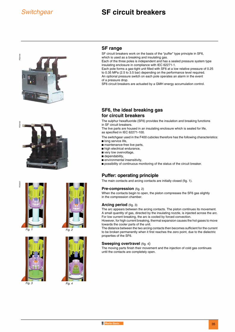
4 SF circuit breakers work on the basis of the “puffer” type principle in SF6, which is used as a breaking and insulating gas. Each of the three poles is independent and has a sealed pressure system type insulating enclosure in compliance with IEC 62271-1. Each pole forms a gas-tight unit filled with SF6 at a low relative pressure of 0.25 to 0.35 MPa (2.5 to 3.5 bar) depending on the performance level required.An optional pressure switch on each pole operates an alarm in the event of a pressure drop.SF6 circuit breakers are actuated by a GMH energy accumulation control.
SF6, the ideal breaking gas for circuit breakers
PE
5018
3 The sulphur hexafluoride (SF6) provides the insulation and breaking functions in SF circuit breakers.The live parts are housed in an insulating enclosure which is sealed for life, as specified in IEC 62271-100.
The switchgear used in the F400 cubicles therefore has the following characteristics:b long service life,b maintenance-free live parts,b high electrical endurance,b very low overvoltage,b dependability,b environmental insensitivity,b possibility of continuous monitoring of the status of the circuit breaker.
Puffer: operating principle
PE
5503
7 The main contacts and arcing contacts are initially closed (fig. 1).
Pre-compression (fig. 2)When the contacts begin to open, the piston compresses the SF6 gas slightly in the compression chamber.
Arcing period (fig. 3)The arc appears between the arcing contacts. The piston continues its movement. A small quantity of gas, directed by the insulating nozzle, is injected across the arc.For low current breaking, the arc is cooled by forced convection.However, for high current breaking, thermal expansion causes the hot gases to move towards the cooler parts of the unit.The distance between the two arcing contacts then becomes sufficient for the current to be broken permanently when it first reaches the zero point, due to the dielectric properties of the SF6.
Sweeping overtravel (fig. 4)The moving parts finish their movement and the injection of cold gas continues until the contacts are completely open.
Fig. 1 Fig. 2
Fig. 3 Fig. 4

36
Switchgear GMH operating mechanism 0
0283
68
SF circuit breakers are actuated by the GMH operating mechanism which ensures that the closing and opening speed of the breaking device is not operator-dependent.
The circuit breakers are fitted with a GMH electrical operating mechanism. They are used for remote operation and to ensure a fast resetting cycle.
The GMH electrical operating mechanism includes: b an energy accumulation mechanism that stores, in the springs, the energy required to close and open the breaker,b a manual lever-operated resetting device,b an electrical motor-operated resetting device that automatically resets the control as soon as the breaker closes (time y 15 s),b a mechanical opening and closing device operated by two pushbuttons on the front panel,b an electrical closing device including: v a closing release for remote control with an anti-pumping relay,b an electrical opening device including one or more opening releases that may be one of the following types:v power on,v undervoltage,v a low consumption mitop(1),b an operation counter,b an optional reset control indication contact,b a resetting limit switch contact,b a black/white mechanical “open-closed” position indicator,b a multi-pin connector to isolate auxiliary circuits in the “racked out” position.
Auxiliary contactsThe GMH operating mechanism is fitted with a block of 14 auxiliary contacts including:b 1 changeover contact for the electrical control,b 1 changeover contact for indication,b 1 contact for the power-on release. The number of available contacts depends on the composition of the control and on the options selected (see table below).
(1) Mitop: release with its own optional current used in combination with the Sepam 100 LA protection relay.
Rated current 10 ABreaking capacity AC 10 A at 220 V (cos ϕ u 0.3)
DC 1.5 A at 110 or 220 V (L/R y 0.01 s)
GMH operating mechanism characteristics
Types of auxiliaries Spring charging motor
Closing release
Opening release Available contactsPower on Undervoltage Mitop C/O O/C Changeoversingle dual
Power supply voltage AC (V) 50 Hz 50 to 55 - 100 to 140 - 220 to 250 - 38060 Hz 110 to 127 - 200 to 250
DC (V) 24 to 33 - 48 to 60 - 110 to 136 - 220 to 260Consumption AC (VA) 700 120 120 240 400/100(2)
DC (W) 570 70 70 140 100/10(2)
Possibility of combining auxiliaries and quantities
b 1 b 1 b 1 b 1 3 4 1or b 1 b 1 b 1 3 4 1or b 1 b 1 b 2 3 3 1or b 1 b 1 b 1 b 1 3 3 1or b 1 b 1 b 1 3 3 1or b 1 b 1 b 1 3 5 1or b 1 b 1 b 1 b 1 3 4 1or b 1 b 1 b 1 b 1 3 3 1
(2) Pick-up/latched consumption.
37
Switchgear GMH operating mechanism 0
Auxiliaries diagram
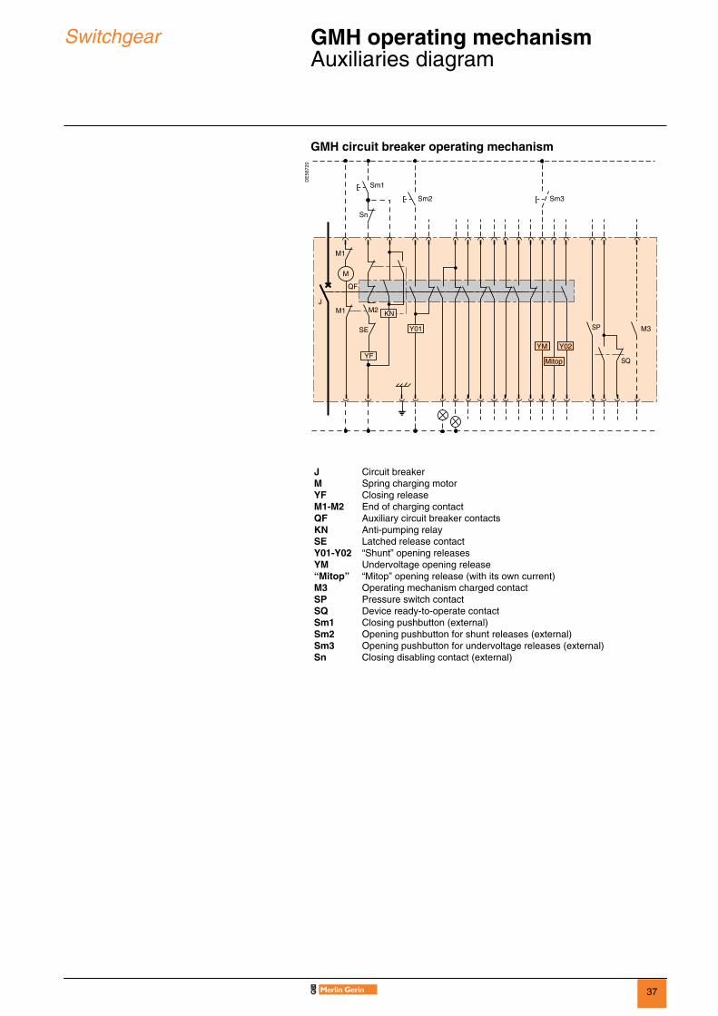
GMH circuit breaker operating mechanism
DE
5672
0
JMYFM1-M2QFKNSEY01-Y02YM“Mitop”M3SPSQSm1Sm2Sm3Sn
Circuit breakerSpring charging motorClosing releaseEnd of charging contactAuxiliary circuit breaker contactsAnti-pumping relayLatched release contact“Shunt” opening releasesUndervoltage opening release“Mitop” opening release (with its own current)Operating mechanism charged contactPressure switch contactDevice ready-to-operate contactClosing pushbutton (external)Opening pushbutton for shunt releases (external)Opening pushbutton for undervoltage releases (external)Closing disabling contact (external)
Sm1
Sn
KN
Y01
M2
SE
YF
JM1
M
QF
SP
M1
SQ
M3
Sm2 Sm3
YM
Mitop
Y02

38
Switchgear Circuit breaker selection guide SF1, SF2 0
Circuit breakersType of cubicle Type of circuit breaker
Incomer/feederBussectioning
SF1 - SF2
Electric resetting device with opening and closing mechanism (GMH)
b
“Shunt” closing release bOpening release 1 release b
2 releases vWithdrawable part rack-in padlocking b
Maximum combinations of available releases and auxiliary contacts“Shunt” release Undervoltage Mitop Contactssingle dual C/O O/C changeoverb 1 b 1 3 4 1b 1 b 1 3 4 1
b 1 b 1 3 3 1b 1 b 1 3 3 1
Auxiliary voltagesSpring charging motor
DC 24 48 110 127 220 250AC 50/60 Hz 48 110 120 220 250Opening or closing coils
DC 24 48 110 127 220AC 50 Hz 110 220 240AC 60 Hz 120 240
Performance table (IEC 62271-100)Type of circuit breaker SF1 SF2
Rated voltage kV, 50/60 Hz 36 40.5 36 36 36 36 36 40.5Insulation level kV, rms 50 Hz - 1 mm 70 85 70 70 70 70 70 95
kV impulse 1.2/50 µs 170 185 170 170 170 170 170 185Rated current Ia 1250 A b b b b b
2500 A b b b bBreaking capacity Isc kA, rms 25 25 25 31.5 31.5 40 40 31.5Making capacity kA, peak 63 63 63 79 79 100 100 79Permissible rated short-time withstand current kA, rms 3 s 25 25 25 31.5 31.5 40 40 31.5Capacitor breaking capacity for rated current 1250 A 875 875 875 875 875
2500 A 1500 1500 1500Operating sequence O - 3 min - CO 3 min - CO b b b b b b b b
O - 0.3 s CO - 3 min CO b b b b b bO - 0.3 s - CO 15 s - CO b b
Operating time opening in ms 50 50 50 50 50 50 50 50breaking in ms 65 65 65 65 65 65 65 65closing in ms 70 70 70 70 70 70 70 70
Cubicle width 900 mm b b b1100 mm b b b b b b b b
39
Installation F400 connection
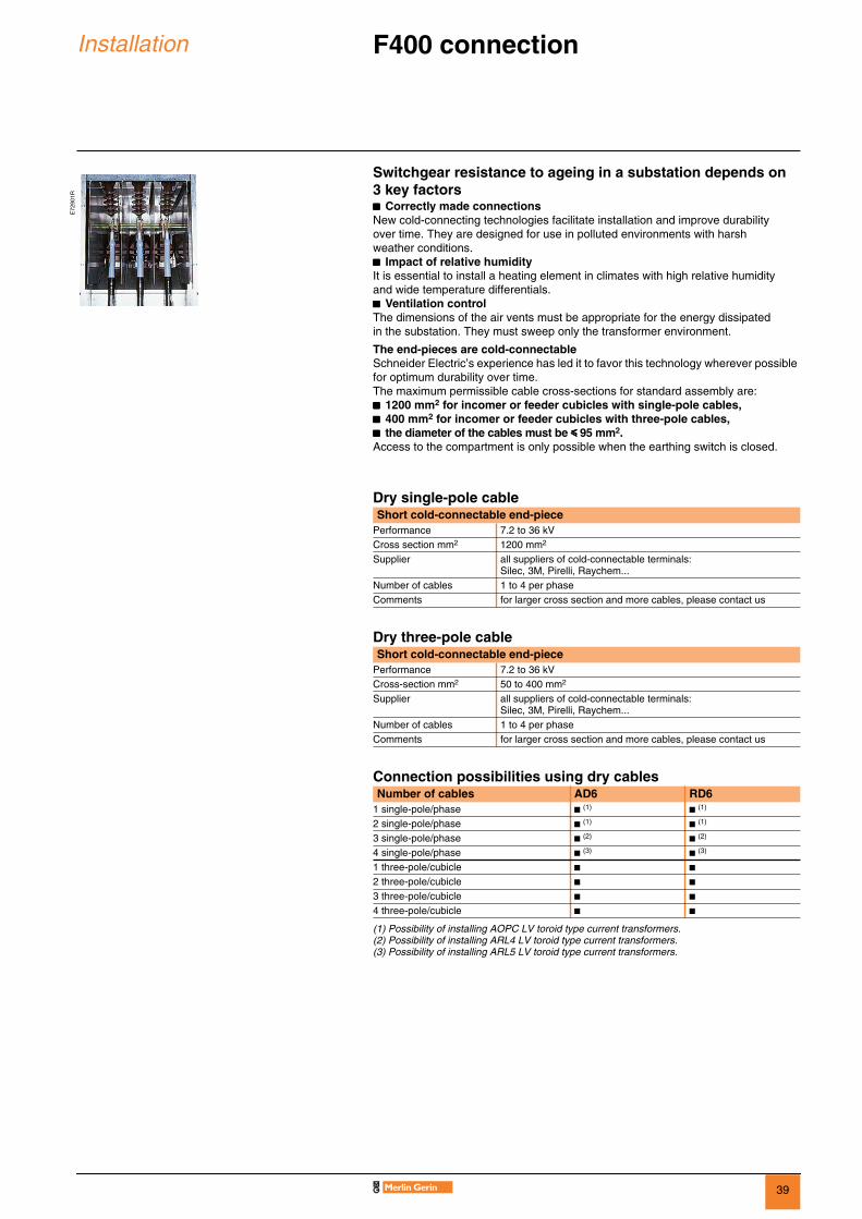
Switchgear resistance to ageing in a substation depends on 3 key factorsbbbb Correctly made connectionsNew cold-connecting technologies facilitate installation and improve durability over time. They are designed for use in polluted environments with harsh weather conditions.bbbb Impact of relative humidityIt is essential to install a heating element in climates with high relative humidity and wide temperature differentials.bbbb Ventilation controlThe dimensions of the air vents must be appropriate for the energy dissipated in the substation. They must sweep only the transformer environment.
The end-pieces are cold-connectableSchneider Electric’s experience has led it to favor this technology wherever possible for optimum durability over time. The maximum permissible cable cross-sections for standard assembly are: bbbb 1200 mm2 for incomer or feeder cubicles with single-pole cables,bbbb 400 mm2 for incomer or feeder cubicles with three-pole cables,bbbb the diameter of the cables must be yyyy 95 mm2.Access to the compartment is only possible when the earthing switch is closed.
Dry single-pole cable
Dry three-pole cable
Connection possibilities using dry cables
(1) Possibility of installing AOPC LV toroid type current transformers.(2) Possibility of installing ARL4 LV toroid type current transformers.(3) Possibility of installing ARL5 LV toroid type current transformers.
E72
901R
Short cold-connectable end-piecePerformance 7.2 to 36 kVCross section mm2 1200 mm2
Supplier all suppliers of cold-connectable terminals: Silec, 3M, Pirelli, Raychem...
Number of cables 1 to 4 per phaseComments for larger cross section and more cables, please contact us
Short cold-connectable end-piecePerformance 7.2 to 36 kVCross-section mm2 50 to 400 mm2
Supplier all suppliers of cold-connectable terminals: Silec, 3M, Pirelli, Raychem...
Number of cables 1 to 4 per phaseComments for larger cross section and more cables, please contact us
Number of cables AD6 RD61 single-pole/phase b (1) b (1)
2 single-pole/phase b (1) b (1)
3 single-pole/phase b (2) b (2)
4 single-pole/phase b (3) b (3)
1 three-pole/cubicle b b2 three-pole/cubicle b b3 three-pole/cubicle b b4 three-pole/cubicle b b

40
Installation Dimensions
Type Un (kV) In (A) No. of cables
Additional DIN format CT
Width Depth Height without PT control cabinet
Height with PT control cabinet
Mass without VT
Mass with VT
AD6/RD6 36 1250 2 900 2670 2255 2335 1095 13204 900 3020 2255 2335 1095 13202 or 4 1100 3020 2255 2335 1340 1610
b 1100 3220 2255 2335 1610 18352500 4 1100 3020 2255 2335 1560 1790
b 1100 3220 2255 2335 1790 201540.5 1250 2 or 4 1100 3020 2255 2335 1340 1610
b 1100 3220 2255 2335 1610 1835CL6 36 1250 900 3020 2255 2335 940 1160
1100 3020 2255 2335 1150 14202500 1100 3020 2255 2335 1150 1420
40.5 1250 1100 3020 2255 2335 1150 1420GL6 36 1250 1100 3020 2255 2335 740 970
2500 1100 3020 2255 2335 740 97040.5 1250 1100 3020 2255 2335 740 970
TT6 36 900 2670 2335 12001100 2670 2335 1140
40.5 1250 1100 2670 2335 1140LB6 36 1250 1100 2670 2255 930
2500 1100 2670 2255 93040.5 1250 1100 2670 2255 930
PE
5632
1P
E56
322
PE
5632
3

41
Installation Dimensions with internal arc withstand 0
Type Un (kV) In (A) No. of cables
Additional DIN format CT in at least one switchboard cubicle
Width Depth Height without PTcontrol cabinet
Height with PT control cabinet
Mass without VT
Mass with VT
AD6/RD6 36 1250 4 maximum 900 3074 2255 2335 1246 14671100 3074 2255 2335 1491 1712
b 900 3274 2255 2335 1467 16921100 3274 2255 2335 1712 1937
2500 4 maximum 1100 3074 2255 2335 1710 1929b 1100 3274 2255 2335 1929 2154
40.5 1250 4 maximum 1100 3074 2255 2335 1710 1929b 1100 3274 2255 2335 1929 2154
CL6 36 1250 900 3074 2255 2335 1091 13121100 3074 2255 2335 1233 1462
b 900 3274 2255 2335 1150 13701100 3274 2255 2335 1313 1542
2500 1100 3074 2255 2335 1233 1462b 1100 3274 2255 2335 1313 1542
40.5 1250 1100 3074 2255 2335 1233 1462b 1100 3274 2255 2335 1313 1542
GL6 36 1250 1100 3074 2255 2335 890 1119b 1100 3274 2255 2335 970 1199
2500 1100 3074 2255 2335 890 1119b 1100 3274 2255 2335 970 1199
40.5 1250 1100 3074 2255 2335 890 1119b 1100 3274 2255 2335 970 1199
TT6 36 900 3074 2335 10811100 3074 2335 1010
b 900 3274 2335 11411100 3274 2335 1090
40.5 1250 1100 3074 2335 1010b 1100 3274 2335 1090
LB6 36 1250 1100 3074 2255 1010b 1100 3274 2255 1090
2500 1100 3074 2255 1010b 1100 3274 2255 1090
40.5 1250 1100 3074 2255 1010b 1100 3274 2255 1090
PE
5632
4P
E56
325
42
Installation Implementation examples 0
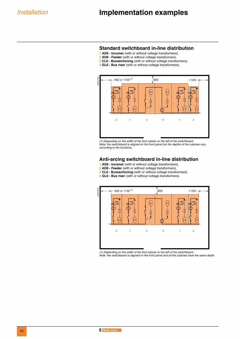
Standard switchboard in-line distribution1 AD6 - Incomer (with or without voltage transformers).2 AD6 - Feeder (with or without voltage transformers).3 CL6 - Bussectioning (with or without voltage transformers).4 GL6 - Bus riser (with or without voltage transformers).
(1) Depending on the width of the first cubicle on the left of the switchboard.Note: the switchboard is aligned on the front panel but the depths of the cubicles vary according to the functions.
Anti-arcing switchboard in-line distribution1 AD6 - Incomer (with or without voltage transformers).2 AD6 - Feeder (with or without voltage transformers).3 CL6 - Bussectioning (with or without voltage transformers).4 GL6 - Bus riser (with or without voltage transformers).
(1) Depending on the width of the first cubicle on the left of the switchboard.Note: the switchboard is aligned on the front panel and all the cubicles have the same depth.
DE
5672
1EN
DE
5672
2EN
800900 or 1100 (1)
800900 or 1100 (1)

43
Installation Implementation examples (continued) 0
“Duplex” distribution“Duplex” distribution can be implemented in two ways:b interconnection by means of cables,b interconnection by means of insulated busbars (on request).b interconnection by means of busbars in a tunnel.
1 Incomer (with or without voltage transformers).2 Feeder (with or without voltage transformers).3 Transversal bussectioning with a busbar or cable system and a disconnector unit (represented by the dotted line).
(1) Depending on the width of the first cubicle on the left of the switchboard.
Interconnections by means of cables
DE
5672
3EN
PE
5632
6800
800
2200
900 or 1100 (1)
44
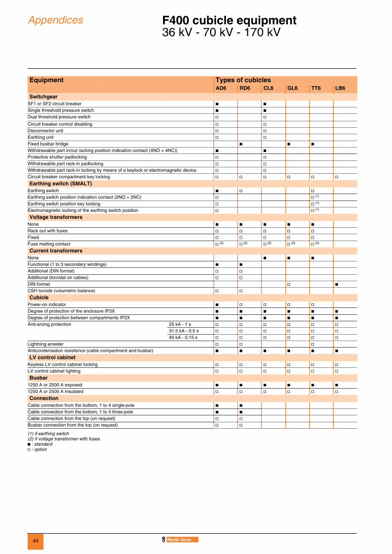
Appendices F400 cubicle equipment 0
36 kV - 70 kV - 170 kV
Equipment Types of cubiclesAD6 RD6 CL6 GL6 TT6 LB6
SwitchgearSF1 or SF2 circuit breaker b bSingle threshold pressure switch b bDual threshold pressure switch v v
Circuit breaker control disabling v vDisconnector unit v vEarthing unit v vFixed busbar bridge b b bWithdrawable part in/out racking position indication contact (4NO + 4NC)) b bProtective shutter padlocking v vWithdrawable part rack-in padlocking v vWithdrawable part rack-in locking by means of a keylock or electromagnetic device v vCircuit breaker compartment key locking v v v v v v
Earthing switch (SMALT)Earthing switch b v vEarthing switch position indication contact (2NO + 2NC) v v (1)
Earthing switch position key locking v v (1)
Electromagnetic locking of the earthing switch position v v (1)
Voltage transformersNone b b b b bRack out with fuses v v v v vFixed v v v v vFuse melting contact v (2) v (2) v (2) v (2) v (2)
Current transformersNone b b bFunctional (1 to 3 secondary windings) b bAdditional (DIN format) v vAdditional (toroidal on cables) v vDIN format v bCSH toroids (volumetric balance) v v
CubiclePower-on indicator b v v v vDegree of protection of the enclosure IP3X b b b b b bDegree of protection between compartments IP2X b b b b b bAnti-arcing protection 25 kA - 1 s v v v v v v
31.5 kA - 0.5 s v v v v v v40 kA - 0.15 s v v v v v v
Lightning arrester v v vAnticondensation resistance (cable compartment and busbar) b b b b b b
LV control cabinetKeyless LV control cabinet locking v v v v v vLV control cabinet lighting v v v v v v
Busbar1250 A or 2500 A exposed b b b b b b1250 A or 2500 A insulated v v v v v v
ConnectionCable connection from the bottom, 1 to 4 single-pole b bCable connection from the bottom, 1 to 4 three-pole b bCable connection from the top (on request) v vBusbar connection from the top (on request) v v
(1) if earthing switch(2) if voltage transformer with fusesb : standardv : option

45
Appendices F400 cubicle equipment 0
40.5 kV - 95 kV - 185 kV
Equipment Types of cubiclesAD6 RD6 CL6 GL6 TT6 LB6
SwitchgearSF1 or SF2 circuit breaker b bSingle threshold pressure switch b bDual threshold pressure switch v v
Circuit breaker control disabling v vDisconnector unit v vEarthing unit v vFixed busbar bridge b b bWithdrawable part in/out racking position indication contact (4NO + 4NC) b bProtective shutter padlocking v vWithdrawable part rack-in padlocking v vWithdrawable part rack-in locking by means of a keylock or electromagnetic device v vCircuit breaker compartment key locking v v v v v v
Earthing switch (SMALT)Earthing switch b v vEarthing switch position indication contact (2NO + 2NC) v v (1)
Earthing switch position key locking v v (1)
Electromagnetic locking of the earthing switch position v v (1)
Voltage transformersNone b b b b bRack out with fuses v v v v vFixed v v v v vFuse melting contact v (2) v (2) v (2) v (2) v (2)
Current transformersNone b b bFunctional (1 to 3 secondary windings) b bAdditional (DIN format) v vAdditional (toroidal on cables) v vDIN format v bCSH toroids (volumetric balance) v v
CubiclePower-on indicator b v v v vDegree of protection of the enclosure IP3X b b b b b bDegree of protection between compartments IP2X b b b b b bAnti-arcing protection 25 kA - 1 s v v v v v v
31.5 kA - 0.5 s v v v v v v40 kA - 0.15 s v v v v v v
Lightning arrester v v vAnticondensation resistance (cable compartment and busbar) b b b b b b
LV control cabinetKeyless LV control cabinet locking v v v v v vLV control cabinet lighting v v v v v v
Busbar1250 A insulated b b b b b b
ConnectionCable connection from the bottom, 1 to 4 single-pole b bCable connection from the bottom, 1 to 4 three-pole b bCable connection from the top (on request) v vBusbar connection from the top (on request) v v(
(1) f earthing switch(2) if voltage transformer with fusesb : standardv : option

46
Notes 0

47
Notes 0

48
Notes 0


AM
TE
D39
9053
EN
© 2
006
Sch
neid
er E
lect
ric -
All
right
s re
serv
ed
89, boulevard Franklin RooseveltF - 92500 Rueil-Malmaison (France)Tel.: +33 (0)1 41 29 85 00
http://www.schneider-electric.comhttp://www.merlin-gerin.com
As standards, specifications and designs change from time to time, please ask for confirmation of the information given in this publication.
Publishing: Schneider ElectricProduction: Esquisse, GraphèmePrinting: Imprimerie du Pont-de-Claix - Made in France
06/2006
This document has been printed on ecological paper
Schneider Electric Industries SAS
ART.28744