13th may 2011 - ieeeewh.ieee.org/conf/icra/2011/workshops/space... · 13th may 2011 hiroshi ueno...
TRANSCRIPT
Japanese Experiment Module
ICRA 2011@Shanghai (2011/May/13) 1
Japanese Experiment Module (JEM) Berthing Evaluation
13th May 2011
Hiroshi UenoHuman Space Systems and Utilization Mission Directorate
Japan Aerospace Exploration Agency (JAXA)

Japanese Experiment Module
ICRA 2011@Shanghai (2011/May/13) 2
Outline
1. Japanese Experiment Module ’Kibo’2. Assembly Sequences of JEM3. Berthing Operation Consideration of EF, ES4. Initial Checkout of JEMRMS5. Berthing Operation by JEMRMS
Japanese Experiment Module
ICRA 2011@Shanghai (2011/May/13) 3
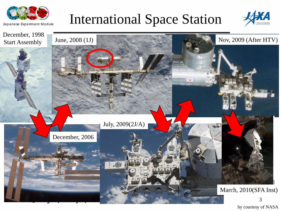
International Space Station
by courtesy of NASA
June, 2008 (1J)
December, 2006
December, 1998Start Assembly
July, 2009(2J/A)
Nov, 2009 (After HTV)
March, 2010(SFA Inst)

Japanese Experiment Module
ICRA 2011@Shanghai (2011/May/13) 4
Japanese Experiment Module ‘Kibo’Assembly & Maintenance Events
Experiment Logistics Module (Pressurized Section) (ELM-PS)
JEM Remote Manipulator System(JEMRMS-MA)
Exposed Facility (EF)
JEM
Pressurized Module (PM)
①1J/A
②1J
③2J/A
Experiment Logistics Module (ExposedSection) (ELM-ES)
by courtesy of NASA
① 2008/03 1J/A ELM-PS:ELM Pressurized Section② 2008/06 1J PM:Pressurized Module & JEMRMS③ 2008/06 Relocation ELM-PS:④ 2009/07 2J/A EF:Exposed Facility⑤ 2009/07 2J/A ELM-ES:ELM Exposed Section⑥ 2009/07 2J/A Payloads(3)⑦ 2009/09 HTV1 HTV-EP, Payloads(2), (SFA)⑧ 2010/03 Installation JEMRMS SFA(Small Fine Arm) ⑨ 2011/02 HTV2 HTV-EP2,⑩ (2012/01) HTV3 HTV-EP3, Payload(1)
Japanese Experiment Module
ICRA 2011@Shanghai (2011/May/13) 5
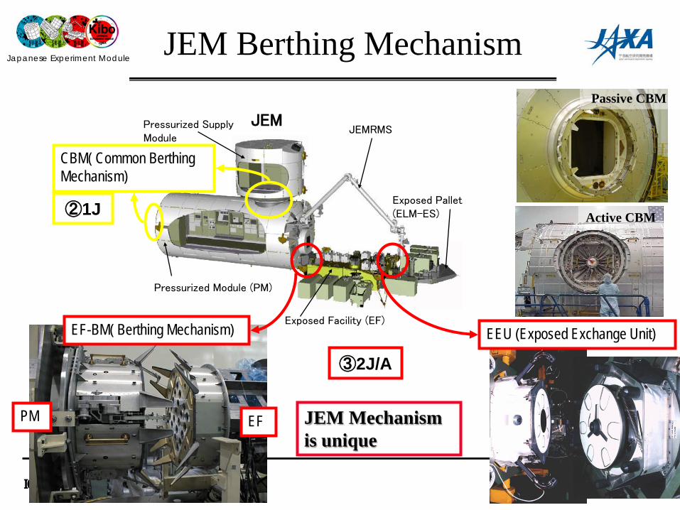
JEM Berthing Mechanism
Pressurized Supply Module
JEMRMS
Exposed Facility (EF)
JEM
Pressurized Module (PM)
Exposed Pallet(ELM-ES)
PM EF
EF-BM( Berthing Mechanism) EEU (Exposed Exchange Unit)
CBM( Common Berthing Mechanism)
③2J/A
②1J
JEM Mechanism is unique
Passive CBM
Active CBM

Japanese Experiment Module
ICRA 2011@Shanghai (2011/May/13) 6
Robot Arms Utilized for Kibo Assembly
JEM RMS-Main Arm (JEMRMS/MA,10m)JEMRS Small Fine
Arm (SFA,2m)
DEXTRE(SPDM)Space Staion RMS(SSRMS,17m)
On-orbit Boom Sensor System(OBSS, 10m)
Shuttle RMS (SRMS,15m)
by courtesy of NASA

Japanese Experiment Module
ICRA 2011@Shanghai (2011/May/13) 7
JEM Remote Manipulator System (JEMRMS)
Main Arm on orbit
Main Arm on ground test
SFA through Airlock
Type Main Arm(MA)
Small Fine Arm(SFA)
DOF 6 6 Lenght Aprox. 9.9m Aprox. 1.9mWeight 780kg 200kgPayload Mass Max 7,000kg Max 300kg
Pstn. Accura.
±50mm ±10mm±1deg ±1deg
Tip Vel.
60mm/s (P/L: <600kg)
50mm/s (P/L: <80kg)
30mm/s (P/L: <3,000kg)
25mm/s (P/L: <300kg)
20mm/s (P/L: <7,000kg)
-
Life 10years or more

Japanese Experiment Module
ICRA 2011@Shanghai (2011/May/13) 8JEMRMS Console
JEMRMS ConsoleConsole on orbit
Console on Ground
by courtesy of NASA
Japanese Experiment Module
ICRA 2011@Shanghai (2011/May/13) 9
Outline
1. Japanese Experiment Module ’Kibo’2. Assembly Sequences of JEM3. Berthing Operation Consideration of EF, ES4. Initial Checkout of JEMRMS5. Berthing Operation by JEMRMS
Japanese Experiment Module
ICRA 2011@Shanghai (2011/May/13) 10by courtesy of NASA
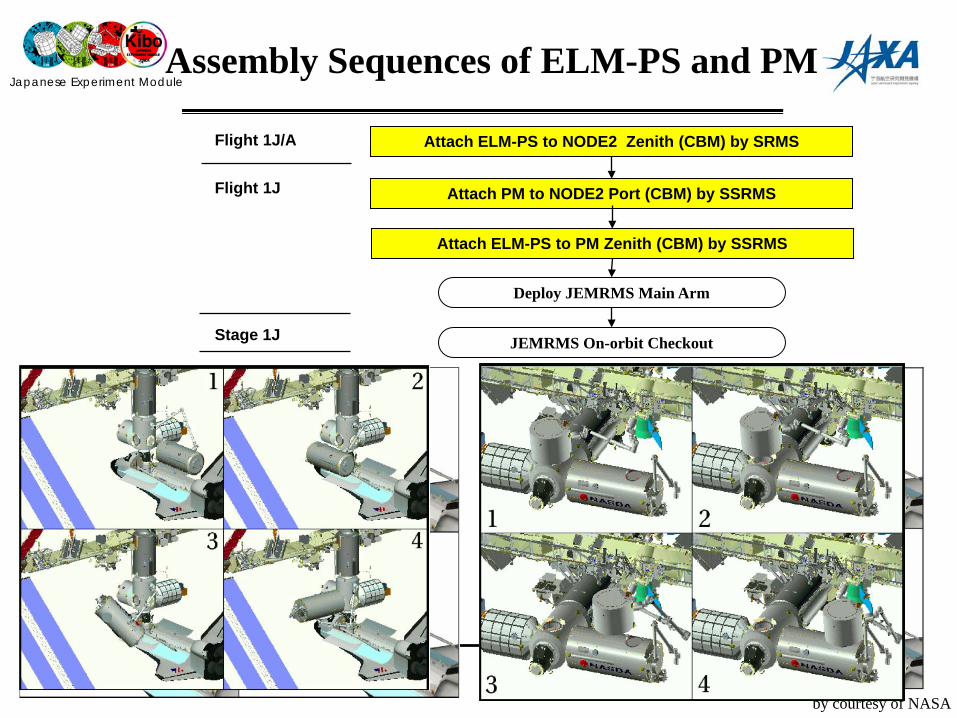
Assembly Sequences of ELM-PS and PM
Attach ELM-PS to NODE2 Zenith (CBM) by SRMS
Attach PM to NODE2 Port (CBM) by SSRMS
Attach ELM-PS to PM Zenith (CBM) by SSRMS
Flight 1J/A
Flight 1J
Stage 1J
Deploy JEMRMS Main Arm
JEMRMS On-orbit Checkout
Japanese Experiment Module
ICRA 2011@Shanghai (2011/May/13) 11
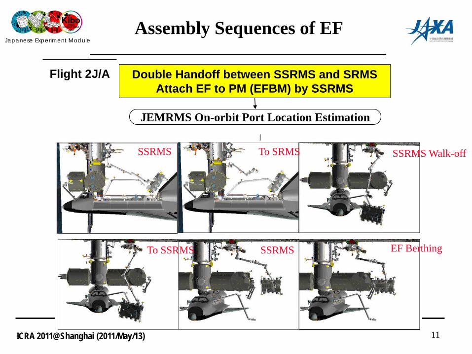
Assembly Sequences of EF
Double Handoff between SSRMS and SRMSAttach EF to PM (EFBM) by SSRMS
Flight 2J/A
JEMRMS On-orbit Port Location Estimation
SSRMS To SRMS SSRMS Walk-off
To SSRMS SSRMS EF Berthing

Japanese Experiment Module
ICRA 2011@Shanghai (2011/May/13) 12
Assembly Sequences of ELM-ES, HTV-EP and Payloads
Handoff ELM-ES from SRMS to SSRMSAttach ELM-ES to EF(EFU#10) by SSRMS
Transfer ICS (Sys. P/L) on ES to EF(EFU#7) by JEMRMSTransfer MAXI (Exp. P/L) on ES to EF(EFU#1) by JEMRMSTransfer SEDA (Exp. P/L) on ES to EF(EFU#9) by JEMRMS
Flight 2J/A
Handoff ELM-ES from SSRMS to SRMSStow ELM-ES to Cargo Bay by SRMS
HTVHandoff HTV-EP from SSRMS to JEMRMSAttach HTV-EP to EF(EFU#10) by JEMRMS
Transfer SMILES (Exp. P/L) on EP to EF(EFU#3) by JEMRMSTransfer HREP(Exp. P/L) on ESPto EF(EFU#6) by JEMRMS
Handoff HTV-EP from JEMRMS to SSRMSStow HTV-EP to HTV by SSRMS

Japanese Experiment Module
ICRA 2011@Shanghai (2011/May/13) 13
Outline
1. Japanese Experiment Module ’Kibo’2. Assembly Sequences of JEM3. Berthing Operation Consideration of EF, ES4. Initial Checkout of JEMRMS5. Berthing Operation by JEMRMS
Japanese Experiment Module
ICRA 2011@Shanghai (2011/May/13) 14
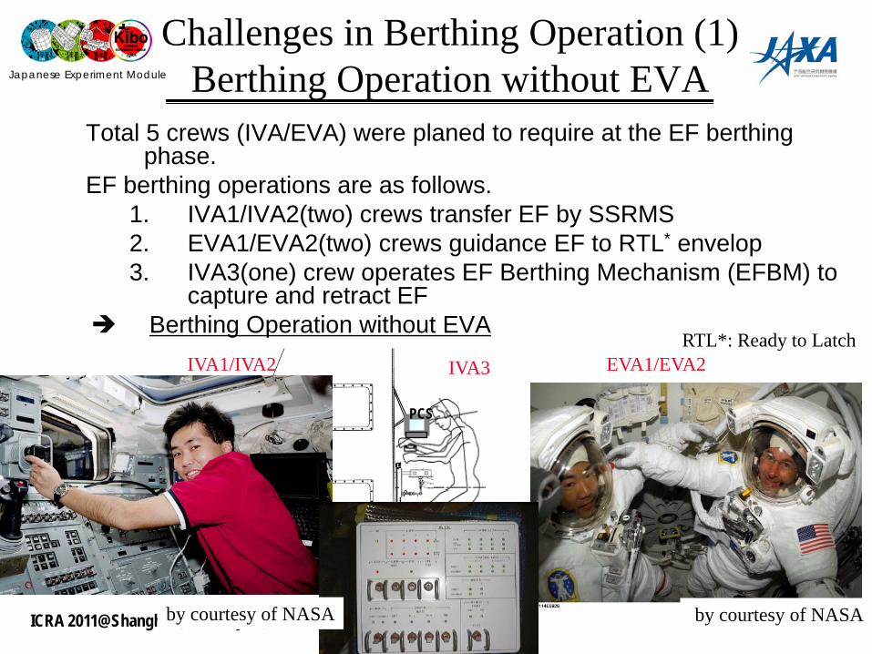
Challenges in Berthing Operation (1)Berthing Operation without EVA
PCS
by courtesy of NASA by courtesy of NASA
Total 5 crews (IVA/EVA) were planed to require at the EF berthing phase.
EF berthing operations are as follows.1. IVA1/IVA2(two) crews transfer EF by SSRMS2. EVA1/EVA2(two) crews guidance EF to RTL* envelop3. IVA3(one) crew operates EF Berthing Mechanism (EFBM) to
capture and retract EF Berthing Operation without EVA
RTL*: Ready to LatchIVA1/IVA2 IVA3 EVA1/EVA2

Japanese Experiment Module
ICRA 2011@Shanghai (2011/May/13)
Challenges in Berthing Operation (1)Berthing Operation without EVA
① Visual Marking on EFBM
15
NASA

Japanese Experiment Module
ICRA 2011@Shanghai (2011/May/13) 16
Challenges in Berthing Operation (1)Berthing Operation without EVA
②Simulation Environments were built and Crews Fly the Approach Operation.(SSRMS Dynamics, Berthing Mechanism (EFBM/EEU)Contact Model, Malfunction of Cameras)
• JEMRMS EE Camera provides excellent view to IVA crew• The three RMSs (SRMS, SSRMS and JEMRMS) are utilized for EF
installation
by courtesy of NASA
SSRMS
JEMRMS
SRMS
Crew Evaluation
JEMRMS EE Camera View
Japanese Experiment Module
ICRA 2011@Shanghai (2011/May/13) 17
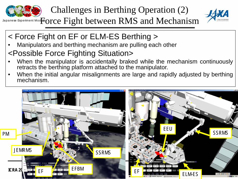
Challenges in Berthing Operation (2)Force Fight between RMS and Mechanism
< Force Fight on EF or ELM-ES Berthing >• Manipulators and berthing mechanism are pulling each other<Possible Force Fighting Situation>• When the manipulator is accidentally braked while the mechanism continuously
retracts the berthing platform attached to the manipulator.• When the initial angular misalignments are large and rapidly adjusted by berthing
mechanism.
SSRMS
EF
PM
JEMRMS
EFBM
SSRMS
ELM-ESEF
EEU
Japanese Experiment Module
ICRA 2011@Shanghai (2011/May/13) 18
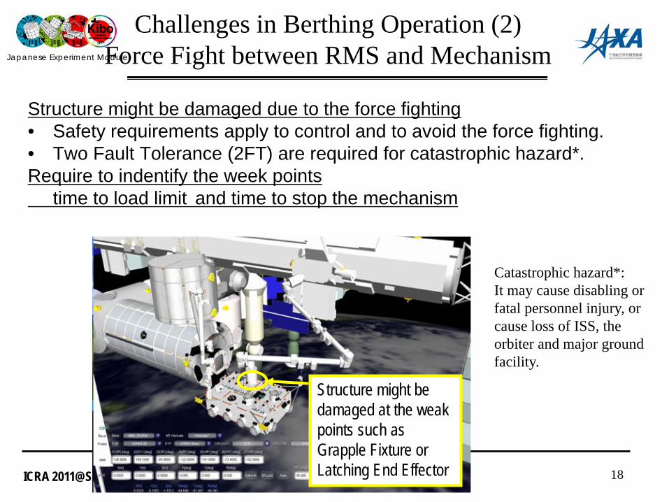
Challenges in Berthing Operation (2)Force Fight between RMS and Mechanism
Structure might be damaged at the weak points such as Grapple Fixture or Latching End Effector
Structure might be damaged due to the force fighting• Safety requirements apply to control and to avoid the force fighting.• Two Fault Tolerance (2FT) are required for catastrophic hazard*.Require to indentify the week points
time to load limit and time to stop the mechanism
Catastrophic hazard*:It may cause disabling or fatal personnel injury, or cause loss of ISS, the orbiter and major ground facility.
Japanese Experiment Module
ICRA 2011@Shanghai (2011/May/13) 19
SLB_1
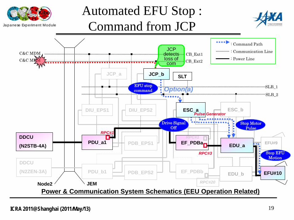
Power & Communication System Schematics (EEU Operation Related)
C&C MDMC&C MDM
CB_Ext1CB_Ext2
●
EFU#9
SLB_2
Node2
Automated EFU Stop : Command from JCP
DDCU
(N2STB-4A)
DDCU
(N2ZEN-3A)
JEM
PDU_b1
PDU_a1 PDB_EPS1
PDB_EPS2
JCP_a JCP_b
EF_PDBb
EF_PDBa
DIU_EPS1 DIU_EPS2
EFU#10
ESC_a ESC_b
SLT
EDU_a
EDU_b
: Command Path: Communication Line: Power Line
RPC#1
RPC#3
RPC#20
RPC#1
Stop EFU Motion
JCP detects loss of com
EFU stop command Option(a)
Drive Signal Off
Pulse Generator
Stop Motor Pulse
Japanese Experiment Module
ICRA 2011@Shanghai (2011/May/13)20
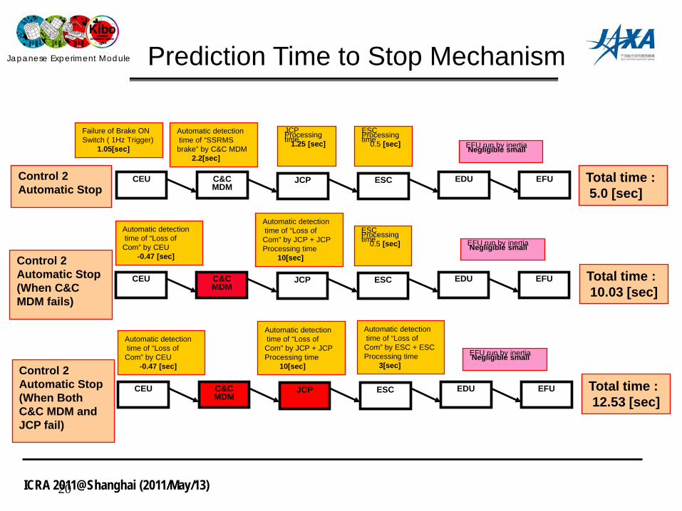
CEU C&C MDM
JCP ESC EDU Total time :5.0 [sec]
EFU
Automatic detectiontime of “SSRMS
brake” by C&C MDM2.2[sec]
JCPProcessingtime1.25 [sec]
ESCProcessingtime0.5 [sec] EFU run by inertiaNegligible small
Control 2Automatic Stop
Prediction Time to Stop Mechanism
CEU C&C MDM
JCP ESC EDU Total time :10.03 [sec]
EFU
Automatic detectiontime of “Loss of
Com” by JCP + JCP Processing time
10[sec]
ESCProcessingtime0.5 [sec]
Control 2Automatic Stop(When C&C MDM fails)
EFU run by inertiaNegligible small
Failure of Brake ON Switch ( 1Hz Trigger)
1.05[sec]
Automatic detectiontime of “Loss of
Com” by CEU-0.47 [sec]
CEU C&C MDM
JCP ESC EDU Total time :12.53 [sec]
EFU
Control 2Automatic Stop(When Both C&C MDM and JCP fail)
EFU run by inertiaNegligible small
Automatic detectiontime of “Loss of
Com” by CEU-0.47 [sec]
Automatic detectiontime of “Loss of
Com” by JCP + JCP Processing time
10[sec]
Automatic detectiontime of “Loss of
Com” by ESC + ESC Processing time
3[sec]

Japanese Experiment Module
ICRA 2011@Shanghai (2011/May/13) 21
Outline
1. Japanese Experiment Module ’Kibo’2. Assembly Sequences of JEM3. Berthing Operation Consideration of EF, ES4. Initial Checkout of JEMRMS5. Berthing Operation by JEMRMS
Japanese Experiment Module
ICRA 2011@Shanghai (2011/May/13)
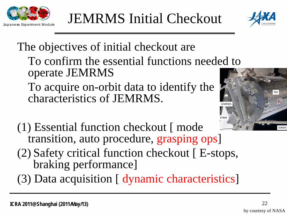
JEMRMS Initial Checkout
The objectives of initial checkout are To confirm the essential functions needed to operate JEMRMSTo acquire on-orbit data to identify the characteristics of JEMRMS.
(1) Essential function checkout [ mode transition, auto procedure, grasping ops]
(2) Safety critical function checkout [ E-stops, braking performance]
(3) Data acquisition [ dynamic characteristics]
22
PM
SSRMS
JEMRMS
EFBM
by courtesy of NASA
Japanese Experiment Module
ICRA 2011@Shanghai (2011/May/13)
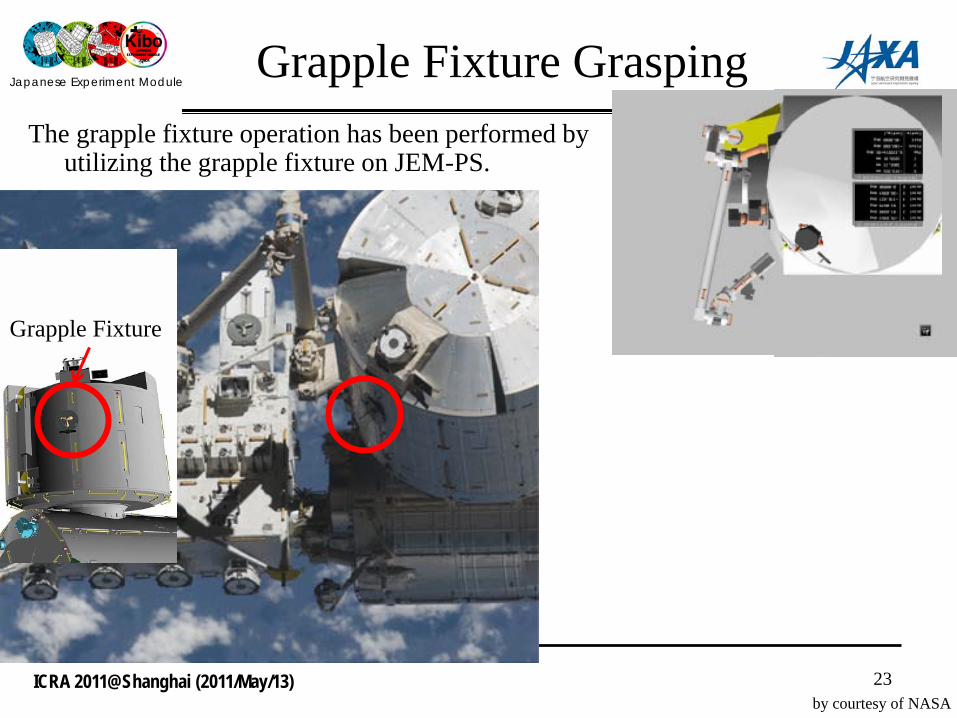
Grapple Fixture GraspingThe grapple fixture operation has been performed by
utilizing the grapple fixture on JEM-PS.
23
Grapple Fixture
by courtesy of NASA
Japanese Experiment Module
ICRA 2011@Shanghai (2011/May/13)
420 425 430 435 440 445 450 455 460-80
-70
-60
-50
-40
-30
-20
-10
0
10
24
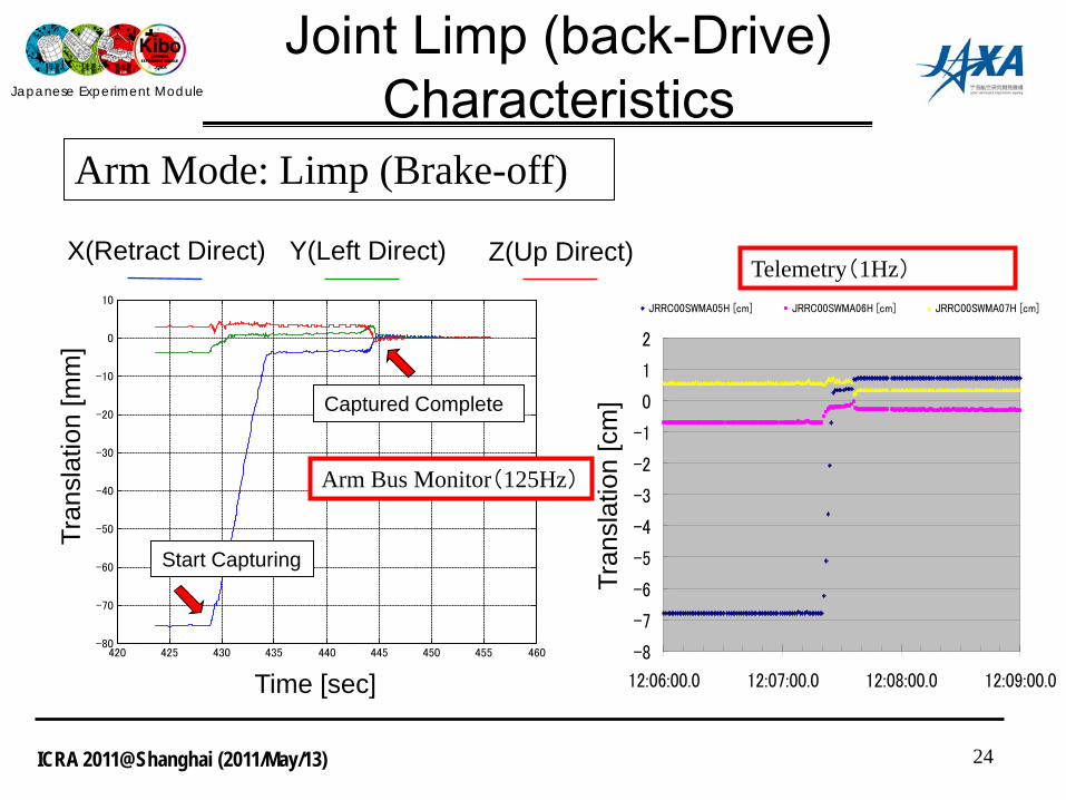
Joint Limp (back-Drive) Characteristics
-8
-7
-6
-5
-4
-3
-2
-1
0
1
2
12:06:00.0 12:07:00.0 12:08:00.0 12:09:00.0
JRRC00SWMA05H [cm] JRRC00SWMA06H [cm] JRRC00SWMA07H [cm]
X(Retract Direct) Y(Left Direct) Z(Up Direct)
Tran
slat
ion
[mm
]
Time [sec]
Start Capturing
Captured Complete
Tran
slat
ion
[cm
]
Arm Mode: Limp (Brake-off)
Telemetry(1Hz)
Arm Bus Monitor(125Hz)

Japanese Experiment Module
ICRA 2011@Shanghai (2011/May/13) 25
420 430 440 450 460-84
-83.5
-83
time [sec] (Zoomed)
Join
t #1 [
deg]
1.153 JEMRMS C/O #3 JLP GF Grapple Ops Step41
420 430 440 450 460
85.9
86
86.1
86.2
86.3
time [sec] (Zoomed)
Join
t #2 [
deg]
Motor Angles x Gear Ratio
420 430 440 450 460-96.5
-96
-95.5
time [sec] (Zoomed)
Join
t #3 [
deg]
2008.08.15 12:03:03 20080815090925-0030
420 430 440 450 460-170.36
-170.34
-170.32
-170.3
-170.28
time [sec] (Zoomed)
Join
t #4 [
deg]
420 430 440 450 460-43
-42.8
-42.6
-42.4
-42.2
time [sec] (Zoomed)
Join
t #5 [
deg]
420 430 440 450 460-0.15
-0.1
-0.05
0
0.05
time [sec] (Zoomed) Join
t #6 [
deg]
Joint Behavior During Limp Motion
420 430 440 450 460-0.1
-0.08
-0.06
-0.04
-0.02
0
0.02
0.04
0.06
0.08
time [sec] (Zoomed)
Joint
#1
[deg
]
1.153 JEMRMS C/O #3 JLP GF Grapple Ops Step41
420 430 440 450 4600
0.02
0.04
0.06
0.08
0.1
0.12
0.14
0.16
time [sec] (Zoomed)
Joint
#2
[deg
]
Joint Ang B - Motor Ang
420 430 440 450 460-0.18
-0.16
-0.14
-0.12
-0.1
-0.08
-0.06
-0.04
-0.02
0
time [sec] (Zoomed)
Joint
#3
[deg
]
2008.08.15 12:03:03 20080815090925-0030
Joint Behavior Difference between Motor and Joint
0.12
[deg
]
Joint Limp (back-Drive) Characteristics

Japanese Experiment Module
ICRA 2011@Shanghai (2011/May/13)
Mot
or A
xis
Out
put A
xis
2480 2500 2520 2540 2560 25800
0.1
0.2
0.3
0.4
time [sec] (Zoomed)
Join
t #1 (M
oto
r A
xis
Resolv
er)
[deg]
1.151 JEMRMS C/O#1 (Dynamics Resp and Resion Ck) Step28
2480 2500 2520 2540 2560 25800
0.1
0.2
0.3
0.4
time [sec] (Zoomed) Join
t #1 (O
utp
ut
Axis
Encord
er
B) [d
eg]
Mot
or A
xis
Out
put A
xis
750 760 770 780 790 800 8100
0.05
0.1
0.15
0.2
0.25
time [sec] (Zoomed) Join
t #1 (M
oto
r A
xis
Resolv
er)
[deg]
1.151 JEMRMS C/O#1 (Dynamics Resp and Resion Ck) Step40
750 760 770 780 790 800 8100
0.1
0.2
0.3
0.4
Dynamics Characteristics
00.05
0.10.15
0.20.25
0 20
0
0.05
0.1
0.15
0.2
0.25
0.3
0 20
Analysis(Extended)

Japanese Experiment Module
ICRA 2011@Shanghai (2011/May/13) 27
Outline
1. Japanese Experiment Module ’Kibo’2. Assembly Sequences of JEM3. Berthing Operation Consideration of EF, ES4. Initial Checkout of JEMRMS5. Berthing Operation by JEMRMS

Japanese Experiment Module
ICRA 2011@Shanghai (2011/May/13)
Port Location EstimationCamera Calibration
28
• The measurement of port location on-orbit to precisely position for the berthing operation.
• The wrist camera calibration to confirm that the parameters are maintained on orbit.
• The wrist camera parameters to obtain on the ground test
JEMRMS
Wrist CameraTarget Marker
JEM-PS
JEM-PM
JEMRMS
JEM-EF
PayloadsPort
JEM-PM
JEM-PS
Japanese Experiment Module
ICRA 2011@Shanghai (2011/May/13) 29
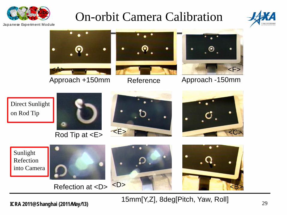
ReferenceApproach +150mm Approach -150mm
15mm[Y,Z], 8deg[Pitch, Yaw, Roll]
<C>
<B><D>
<E>
<A> <F>
Rod Tip at <E>
Refection at <D>
On-orbit Camera Calibration
Sunlight Refection into Camera
Direct Sunlight on Rod Tip

Japanese Experiment Module
ICRA 2011@Shanghai (2011/May/13) 30
On-orbit Camera Calibration
• By neglecting location ‘E’, the estimation errors become the smallest.
• The parameters estimated on orbit are similar to ones of the ground.
Large Deviation
Manual Estimation
Japanese Experiment Module
ICRA 2011@Shanghai (2011/May/13) 31
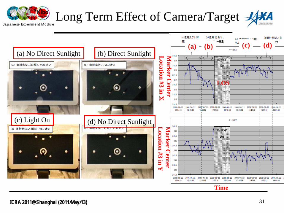
Long Term Effect of Camera/Target
(b) Direct Sunlight(a) No Direct Sunlight
(c) Light On (d) No Direct Sunlight
(a) (b) (c) (d)
Time
LOS
Marker C
enter L
ocation #3 in XM
arker Center
Location #3 in Y
Japanese Experiment Module
ICRA 2011@Shanghai (2011/May/13)
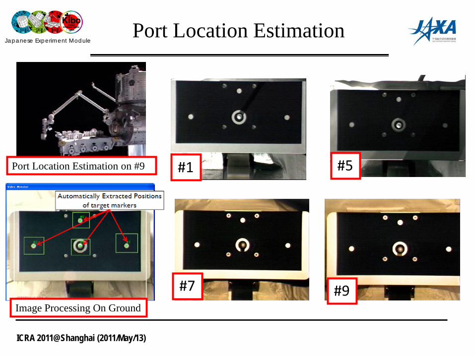
Port Location Estimation
#1 #5
#7 #9Image Processing On Ground
Port Location Estimation on #9

Japanese Experiment Module
ICRA 2011@Shanghai (2011/May/13)
Payload Berthing by Kibo Robot Arm
Three Payloads were assembled by Astronauts tele-operation. (July ‘09)
Handling and Berthing Large Size Pallet (2300kg) were also successful . (Sept’09 , Feb ‘11)
Handling After Installation
Handling EP
Positioning EP
Standard Payload SpecificationMass: 500kgShape: 0.8 x 1.0 x 1.8 mInterface Function- Robot Arm- Equipment Exchange Unit
by courtesy of NASA

Japanese Experiment Module
ICRA 2011@Shanghai (2011/May/13)
JEMRMS Base Offset
• Estimate the base offset from the location of five ports
• Find the base offset to be the pressurized deformation and zero-gravity effect.
34
X[mm] Y[mm] Z[mm] R[deg] P[deg] Y[deg]Design -20.3 -9.6 22.3 -0.02 -0.71 -0.37Estimated Error 2.5 1.6 3.9 0.00 0.08 0.06Max in Design -22.8 -11.1 18.5 -0.02 -0.79 -0.43Min in Design -17.7 -8.0 26.2 -0.02 -0.63 -0.31
Estimated Offset -28.1 -6.3 16.8 0.15 -0.75 -0.53Difference 5.3 1.8 1.6 0.17 ○ 0.10
EF Coordinates@RMS Coordinates
Japanese Experiment Module
ICRA 2011@Shanghai (2011/May/13)
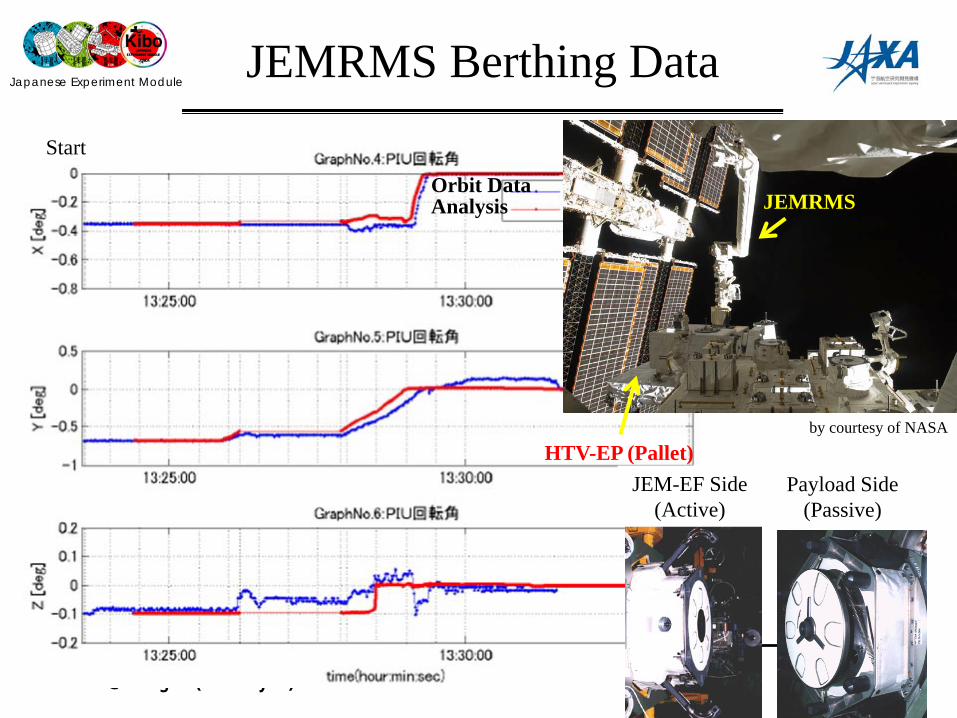
JEMRMS Berthing Data
35
Orbit DataAnalysis
EndStart
JEM-EF Side (Active)
Payload Side (Passive)
HTV-EP (Pallet)
JEMRMS
by courtesy of NASA