14 engine cooling
TRANSCRIPT

ENGINECOOLING

14-1
ENGINECOOLING
CONTENTS
GENERAL INFORMATION 2. . . . . . . . . . . . . . . . . .
SERVICE SPECIFICATIONS 2. . . . . . . . . . . . . . . . .
LUBRICANT 2. . . . . . . . . . . . . . . . . . . . . . . . . . . . . . .
SEALANTS 3. . . . . . . . . . . . . . . . . . . . . . . . . . . . . . . .
SPECIAL TOOL 3. . . . . . . . . . . . . . . . . . . . . . . . . . . .
TROUBLESHOOTING 3. . . . . . . . . . . . . . . . . . . . . . .
ON-VEHICLE SERVICE 8. . . . . . . . . . . . . . . . . . . . . Engine Coolant Leak Checking 8. . . . . . . . . . . . . . . . .
Radiator Cap Valve Opening Pressure Check 8. . .
Engine Coolant Replacement 9. . . . . . . . . . . . . . . . . .
Concentration Measurement 10. . . . . . . . . . . . . . . . .
Fan Controller Check 10. . . . . . . . . . . . . . . . . . . . . . .
Fan Control Relay Continuity Check 11. . . . . . . . . . .
THERMOSTAT 12. . . . . . . . . . . . . . . . . . . . . . . . . . . .
WATER PUMP 14. . . . . . . . . . . . . . . . . . . . . . . . . . . . .
WATER HOSE AND WATER PIPE 15. . . . . . . . . .
RADIATOR 18. . . . . . . . . . . . . . . . . . . . . . . . . . . . . . . .
ENGINE COOLING – General Information/Service Specifications/Lubricant14-2
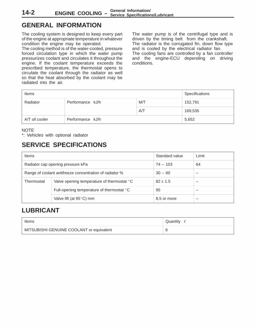
GENERAL INFORMATIONThe cooling system is designed to keep every partof the engine at appropriate temperature in whatevercondition the engine may be operated.The cooling method is of the water-cooled, pressureforced circulation type in which the water pumppressurizes coolant and circulates it throughout theengine. If the coolant temperature exceeds theprescribed temperature, the thermostat opens tocirculate the coolant through the radiator as wellso that the heat absorbed by the coolant may beradiated into the air.
The water pump is of the centrifugal type and isdriven by the timing belt from the crankshaft.The radiator is the corrugated fin, down flow typeand is cooled by the electrical radiator fan.The cooling fans are controlled by a fan controllerand the engine-ECU depending on drivingconditions.
Items Specifications
Radiator Performance kJ/h M/T 152,791
A/T 169,535
A/T oil cooler Performance kJ/h 5,652
NOTE*: Vehicles with optional radiator
SERVICE SPECIFICATIONS
Items Standard value Limit
Radiator cap opening pressure kPa 74 – 103 64
Range of coolant antifreeze concentration of radiator % 30 – 60 –
Thermostat Valve opening temperature of thermostat �C 82�1.5 –
Full-opening temperature of thermostat �C 95 –
Valve lift (at 95�C) mm 8.5 or more –
LUBRICANT
Items Quantity �
MITSUBISHI GENUINE COOLANT or equivalent 6

ENGINE COOLING – Sealants/Special Tool/Troubleshooting 14-3
SEALANTS
Items Specified sealant Remarks
Cylinder block drain plug 3M Nut Locking Part No. 4171 or equivalent Drying sealant
Water pump Mitsubishi Genuine Parts No. MD970389 orequivalent
Semi-drying sealant
Water fittingequivalent
Water outlet fitting
Water by-pass fitting
SPECIAL TOOL
Tool Number Name Use
A
B
C
D
MB991223A: MB991219B: MB991220C: MB991221D: MB991222
Harness setA: Test harnessB: LED harnessC: LED harness
adapterD: probe
Measurement of terminal voltageA: Connector pin contact pressure inspectionB: Power circuit inspectionC: Power circuit inspectionD: Commercial tester connection
TROUBLESHOOTINGINSPECTION CHART FOR TROUBLE SYMPTOMS
Trouble symptoms Inspection procedureNo.
Reference page
Radiator fan and condenser fan do not operate. <Vehicles with A/C>Radiator fan does not operate. <Vehicles without A/C>
1 14-4
Radiator fan and condenser fan do not change speed or stop.<Vehicles with A/C>Radiator fan does not change speed or stop. <Vehicles without A/C>
2 14-6
Radiator fan does not operate. <Vehicles with A/C> 3 14-7
Condenser fan does not operate. <Vehicles with A/C> 4 14-7
ENGINE COOLING – Troubleshooting14-4
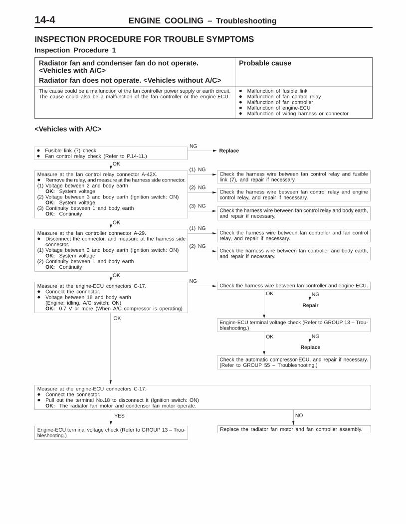
INSPECTION PROCEDURE FOR TROUBLE SYMPTOMSInspection Procedure 1
Radiator fan and condenser fan do not operate. <Vehicles with A/C>Radiator fan does not operate. <Vehicles without A/C>
Probable cause
The cause could be a malfunction of the fan controller power supply or earth circuit.The cause could also be a malfunction of the fan controller or the engine-ECU.
� Malfunction of fusible link� Malfunction of fan control relay� Malfunction of fan controller� Malfunction of engine-ECU� Malfunction of wiring harness or connector
<Vehicles with A/C>
NGReplace
OK(1) NG
Check the harness wire between fan control relay and fusiblelink (7), and repair if necessary.
(2) NGCheck the harness wire between fan control relay and enginecontrol relay, and repair if necessary.
(3) NGCheck the harness wire between fan control relay and body earth,and repair if necessary.
OK NG
Repair
OK NG
Replace
Check the automatic compressor-ECU, and repair if necessary.(Refer to GROUP 55 – Troubleshooting.)
YES NO
Engine-ECU terminal voltage check (Refer to GROUP 13 – Trou-bleshooting.)
Replace the radiator fan motor and fan controller assembly.
OK
Measure at the engine-ECU connectors C-17.� Connect the connector.� Pull out the terminal No.18 to disconnect it (Ignition switch: ON)
OK: The radiator fan motor and condenser fan motor operate.
Engine-ECU terminal voltage check (Refer to GROUP 13 – Trou-bleshooting.)
OK
Measure at the engine-ECU connectors C-17.� Connect the connector.� Voltage between 18 and body earth
(Engine: idling, A/C switch: ON)OK: 0.7 V or more (When A/C compressor is operating)
NGCheck the harness wire between fan controller and engine-ECU.
OK(1) NG
Check the harness wire between fan controller and fan controlrelay, and repair if necessary.
(2) NGCheck the harness wire between fan controller and body earth,and repair if necessary.
Measure at the fan controller connector A-29.� Disconnect the connector, and measure at the harness side
connector.(1) Voltage between 3 and body earth (Ignition switch: ON)
OK: System voltage(2) Continuity between 1 and body earth
OK: Continuity
Measure at the fan control relay connector A-42X.� Remove the relay, and measure at the harness side connector.(1) Voltage between 2 and body earth
OK: System voltage(2) Voltage between 3 and body earth (Ignition switch: ON)
OK: System voltage(3) Continuity between 1 and body earth
OK: Continuity
� Fusible link (7) check� Fan control relay check (Refer to P.14-11.)

ENGINE COOLING – Troubleshooting 14-5
<Vehicles without A/C>
OK(1) NG
Check the harness wire between fan control relay and fusiblelink (7), and repair if necessary.
(2) NGCheck the harness wire between fan control relay and enginecontrol relay, and repair if necessary.
(3) NGCheck the harness wire between fan control relay and body earth,and repair if necessary.
OK(1) NG
Check the harness wire between fan controller and fan controlrelay, and repair if necessary.
(2) NGCheck the harness wire between fan controller and body earth,and repair if necessary.
OK NG
Repair
Engine-ECU terminal voltage check (Refer to GROUP 13 – Trou-bleshooting.)
YES NO
Engine-ECU terminal voltage check (Refer to GROUP 13 – Trou-bleshooting.)
Replace the radiator fan motor and fan controller assembly.
OK
Measure at the engine-ECU connectors C-17.� Connect the connector.� Pull out the terminal No.18 to disconnect it (Ignition switch: ON).
OK: The radiator fan motor operates.
OK
Measure at the engine-ECU connectors C-17.� Connect the connector.� Voltage between 18 and body earth (Engine: idling)
OK: 0.7 V or more (When radiator fan is operating)
NGCheck the harness wire between fan controller and engine-ECU.
Measure at the fan controller connector A-29.� Disconnect the connector, and measure at the harness side
connector.(1) Voltage between 3 and body earth (Ignition switch: ON)
OK: System voltage(2) Continuity between 1 and body earth
OK: Continuity
Measure at the fan control relay connector A-42X.� Remove the relay, and measure at the harness side connector.(1) Voltage between 2 and body earth
OK: System voltage(2) Voltage between 3 and body earth (Ignition switch: ON)
OK: System voltage(3) Continuity between 1 and body earth
OK: Continuity
� Fusible link (7) check� Fan control relay check (Refer to P.14-11.)
NGReplace
ENGINE COOLING – Troubleshooting14-6
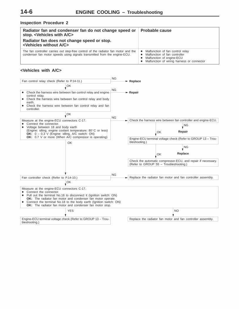
Inspection Procedure 2
Radiator fan and condenser fan do not change speed orstop. <Vehicles with A/C>Radiator fan does not change speed or stop. <Vehicles without A/C>
Probable cause
The fan controller carries out step-free control of the radiator fan motor and thecondenser fan motor speeds using signals transmitted from the engine-ECU.
� Malfunction of fan control relay� Malfunction of fan controller� Malfunction of engine-ECU� Malfunction of wiring harness or connector
<Vehicles with A/C>
OK
NG
Repair
OK
NG
Replace
Check the automatic compressor-ECU, and repair if necessary.(Refer to GROUP 55 – Troubleshooting.)
YES NO
Engine-ECU terminal voltage check (Refer to GROUP 13 – Trou-bleshooting.)
Replace the radiator fan motor and fan controller assembly.
OK
Measure at the engine-ECU connectors C-17.� Connect the connector.� Pull out the terminal No.18 to disconnect it (Ignition switch: ON)
OK: The radiator fan motor and condenser fan motor operate.� Connect the terminal No.18 to the body earth (Ignition switch: ON)
OK: The radiator fan motor and condenser fan motor stop.
OK
Fan controller check (Refer to P.14-10.)NG
Replace the radiator fan motor and fan controller assembly.
Engine-ECU terminal voltage check (Refer to GROUP 13 – Trou-bleshooting.)
OK
Measure at the engine-ECU connectors C-17.� Connect the connector.� Voltage between 18 and body earth
(Engine: idling, engine coolant temperature: 80�C or less)OK: 0 – 0.3 V (Engine: idling, A/C switch: ON)OK: 0.7 V or more (When A/C compressor is operating)
NGCheck the harness wire between fan controller and engine-ECU.
OK
� Check the harness wire between fan control relay and enginecontrol relay.
� Check the harness wire between fan control relay and bodyearth.
� Check the harness wire between fan control relay and fancontroller.
NGRepair
Fan control relay check (Refer to P.14-11.)NG
Replace
ENGINE COOLING – Troubleshooting 14-7
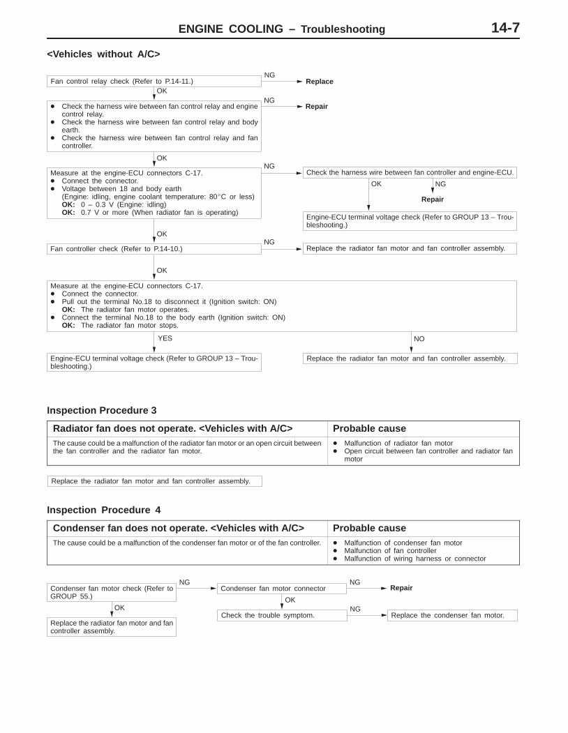
<Vehicles without A/C>
OK NG
Repair
Engine-ECU terminal voltage check (Refer to GROUP 13 – Trou-bleshooting.)
YES NO
Engine-ECU terminal voltage check (Refer to GROUP 13 – Trou-bleshooting.)
Replace the radiator fan motor and fan controller assembly.
OK
Measure at the engine-ECU connectors C-17.� Connect the connector.� Pull out the terminal No.18 to disconnect it (Ignition switch: ON)
OK: The radiator fan motor operates.� Connect the terminal No.18 to the body earth (Ignition switch: ON)
OK: The radiator fan motor stops.
OK
Fan controller check (Refer to P.14-10.)NG
Replace the radiator fan motor and fan controller assembly.
OK
Measure at the engine-ECU connectors C-17.� Connect the connector.� Voltage between 18 and body earth
(Engine: idling, engine coolant temperature: 80�C or less)OK: 0 – 0.3 V (Engine: idling)OK: 0.7 V or more (When radiator fan is operating)
NGCheck the harness wire between fan controller and engine-ECU.
OK
� Check the harness wire between fan control relay and enginecontrol relay.
� Check the harness wire between fan control relay and bodyearth.
� Check the harness wire between fan control relay and fancontroller.
NGRepair
Fan control relay check (Refer to P.14-11.)NG
Replace
Inspection Procedure 3
Radiator fan does not operate. <Vehicles with A/C> Probable causeThe cause could be a malfunction of the radiator fan motor or an open circuit betweenthe fan controller and the radiator fan motor.
� Malfunction of radiator fan motor� Open circuit between fan controller and radiator fan
motor
Replace the radiator fan motor and fan controller assembly.
Inspection Procedure 4
Condenser fan does not operate. <Vehicles with A/C> Probable causeThe cause could be a malfunction of the condenser fan motor or of the fan controller. � Malfunction of condenser fan motor
� Malfunction of fan controller� Malfunction of wiring harness or connector
OK
Replace the radiator fan motor and fancontroller assembly.
OK
Check the trouble symptom.NG
Replace the condenser fan motor.
Condenser fan motor check (Refer toGROUP 55.)
NGCondenser fan motor connector
NGRepair
ENGINE COOLING – On-vehicle Service14-8
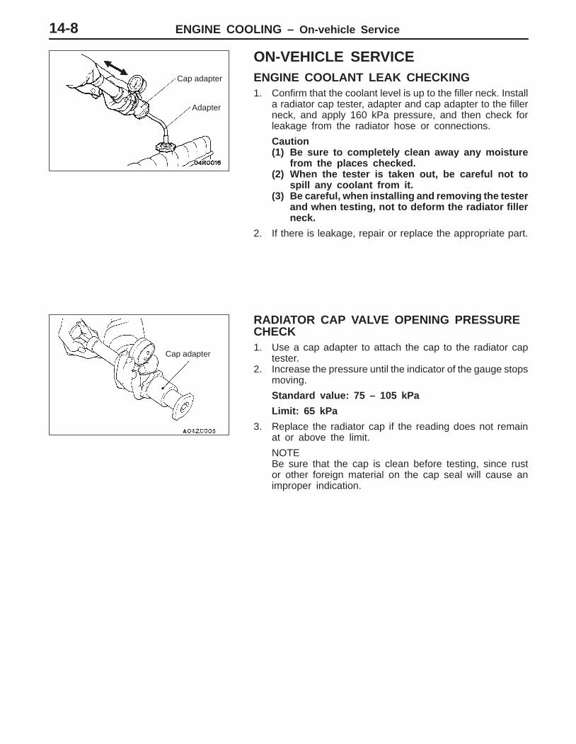
ON-VEHICLE SERVICEENGINE COOLANT LEAK CHECKING1. Confirm that the coolant level is up to the filler neck. Install
a radiator cap tester, adapter and cap adapter to the fillerneck, and apply 160 kPa pressure, and then check forleakage from the radiator hose or connections.
Caution(1) Be sure to completely clean away any moisture
from the places checked.(2) When the tester is taken out, be careful not to
spill any coolant from it.(3) Be careful, when installing and removing the tester
and when testing, not to deform the radiator fillerneck.
2. If there is leakage, repair or replace the appropriate part.
RADIATOR CAP VALVE OPENING PRESSURECHECK1. Use a cap adapter to attach the cap to the radiator cap
tester.2. Increase the pressure until the indicator of the gauge stops
moving.
Standard value: 75 – 105 kPa
Limit: 65 kPa
3. Replace the radiator cap if the reading does not remainat or above the limit.
NOTEBe sure that the cap is clean before testing, since rustor other foreign material on the cap seal will cause animproper indication.
Cap adapter
Adapter
Cap adapter
ENGINE COOLING – On-vehicle Service 14-9
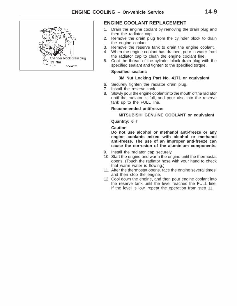
ENGINE COOLANT REPLACEMENT1. Drain the engine coolant by removing the drain plug and
then the radiator cap.2. Remove the drain plug from the cylinder block to drain
the engine coolant.3. Remove the reserve tank to drain the engine coolant.4. When the engine coolant has drained, pour in water from
the radiator cap to clean the engine coolant line.5. Coat the thread of the cylinder block drain plug with the
specified sealant and tighten to the specified torque.
Specified sealant:
3M Nut Locking Part No. 4171 or equivalent
6. Securely tighten the radiator drain plug.7. Install the reserve tank.8. Slowly pour the engine coolant into the mouth of the radiator
until the radiator is full, and pour also into the reservetank up to the FULL line.
Recommended antifreeze:
MITSUBISHI GENUINE COOLANT or equivalent
Quantity: 6 �
CautionDo not use alcohol or methanol anti-freeze or anyengine coolants mixed with alcohol or methanolanti-freeze. The use of an improper anti-freeze cancause the corrosion of the aluminium components.
9. Install the radiator cap securely.10. Start the engine and warm the engine until the thermostat
opens. (Touch the radiator hose with your hand to checkthat warm water is flowing.)
11. After the thermostat opens, race the engine several times,and then stop the engine.
12. Cool down the engine, and then pour engine coolant intothe reserve tank until the level reaches the FULL line.If the level is low, repeat the operation from step 11.
Cylinder block drain plug39 Nm
ENGINE COOLING – On-vehicle Service14-10
CONCENTRATION MEASUREMENTMeasure the temperature and specific gravity of the enginecoolant to check the antifreeze concentration.
Standard value: 30–60% (allowable concentration range)
RECOMMENDED ANTIFREEZE
Antifreeze Allowable concentration
MITSUBISHI GENUINE COOLANTor equivalent
30–60%
CautionIf the concentration of the antifreeze is below 30 %, theanti-corrosion property will be adversely affected. Inaddition, if the concentration is above 60 %, both theanti-freezing and engine cooling properties will decrease,affecting the engine adversely. For these reasons, be sureto maintain the concentration level within the specifiedrange.
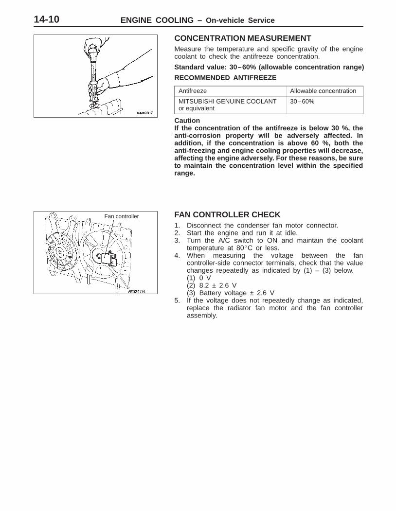
FAN CONTROLLER CHECK1. Disconnect the condenser fan motor connector.2. Start the engine and run it at idle.3. Turn the A/C switch to ON and maintain the coolant
temperature at 80�C or less.4. When measuring the voltage between the fan
controller-side connector terminals, check that the valuechanges repeatedly as indicated by (1) – (3) below.(1) 0 V(2) 8.2 ± 2.6 V(3) Battery voltage ± 2.6 V
5. If the voltage does not repeatedly change as indicated,replace the radiator fan motor and the fan controllerassembly.
Fan controller

ENGINE COOLING – On-vehicle Service 14-11
FAN CONTROL RELAY CONTINUITY CHECK
Battery voltage Terminal No.
1 2 3 4
When current is notsupplied
When current issupplied
Fan control relay
ENGINE COOLING – Thermostat14-12
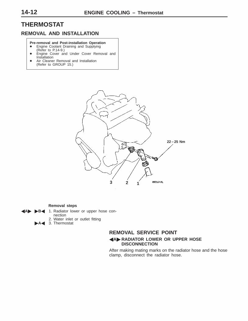
THERMOSTATREMOVAL AND INSTALLATION
Pre-removal and Post-installation Operation� Engine Coolant Draining and Supplying
(Refer to P.14-9.)� Engine Cover and Under Cover Removal and
Installation� Air Cleaner Removal and Installation
(Refer to GROUP 15.)
1
22 – 25 Nm
23
Removal steps�A� �B� 1. Radiator lower or upper hose con-
nection2. Water inlet or outlet fitting
�A� 3. Thermostat
REMOVAL SERVICE POINT�A�RADIATOR LOWER OR UPPER HOSE
DISCONNECTIONAfter making mating marks on the radiator hose and the hoseclamp, disconnect the radiator hose.

ENGINE COOLING – Thermostat 14-13
INSTALLATION SERVICE POINTS�A� THERMOSTAT INSTALLATIONInstall the thermostat so that the jiggle valve is facing straightup.
CautionMake absolutely sure that no oil is adhering to the rubberring of the thermostat. In addition, be careful not to foldover or scratch the rubber ring when inserting. If the rubberring is damaged, replace the thermostat.
�B�RADIATOR LOWER OR UPPER HOSECONNECTION
1. Insert each hose as far as the projection of the waterinlet fitting.
2. Align the mating marks on the radiator hose and hoseclamp, and then connect the radiator hose.
INSPECTIONTHERMOSTAT CHECK1. Immerse the thermostat in water, and heat the water while
stirring. Check the thermostat valve opening temperature.
Standard value: Valve opening temperature: 82 �1.5�C
2. Check that the amount of valve lift is at the standard valuewhen the water is at the full-opening temperature.
Standard value:
Full-opening temperature: 95 �C
Amount of valve lift: 8.5 mm or more
NOTEMeasure the valve height when the thermostat is fullyclosed, and use this measurement to calculate the valveheight when the thermostat is fully open.
Jiggle valve
Rubber ring
Valve lift

ENGINE COOLING – Water Pump14-14
WATER PUMPREMOVAL AND INSTALLATION
Pre-removal and Post-installation Operation� Engine Coolant Draining and Supplying
(Refer to P.14-9.)� Timing Belt Removal and Installation
(Refer to GROUP 11.)� Idler Pulley Removal and Installation
(Refer to GROUP 11A.)
24 Nm
1
10 – 12 Nm
2
Sealant:Mitsubishi Genuine Part No.MD970389 or equivalent
Removal steps1. Timing belt rear cover
�A� 2. Water pump
INSTALLATION SERVICE POINT�A�WATER PUMP INSTALLATIONSqueeze out the sealant from the tube evenly and apply itso that there is not too much sealant and no places withoutsealant.
Specified Sealant:
Mitsubishi Genuine Parts No. MD970389 or equivalent
ENGINE COOLING – Water Hose and Water Pipe 14-15
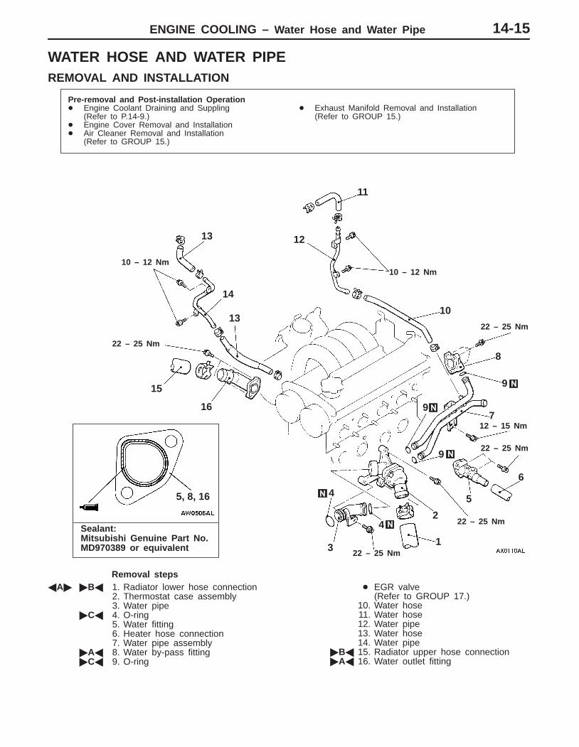
WATER HOSE AND WATER PIPEREMOVAL AND INSTALLATION
Pre-removal and Post-installation Operation� Engine Coolant Draining and Suppling
(Refer to P.14-9.)� Engine Cover Removal and Installation� Air Cleaner Removal and Installation
(Refer to GROUP 15.)
� Exhaust Manifold Removal and Installation(Refer to GROUP 15.)
Sealant:Mitsubishi Genuine Part No.MD970389 or equivalent
10 – 12 Nm
1
10 – 12 Nm
22 – 25 Nm
22 – 25 Nm
22 – 25 Nm
22 – 25 Nm
22 – 25 Nm
5, 8, 16
2
3
4
5
6
7
8
9
10
11
1213
14
15
16
13
9
12 – 15 Nm
9
4
Removal steps�A� �B� 1. Radiator lower hose connection
2. Thermostat case assembly3. Water pipe
�C� 4. O-ring5. Water fitting6. Heater hose connection7. Water pipe assembly
�A� 8. Water by-pass fitting�C� 9. O-ring
� EGR valve (Refer to GROUP 17.)
10. Water hose11. Water hose12. Water pipe13. Water hose14. Water pipe
�B� 15. Radiator upper hose connection�A� 16. Water outlet fitting
ENGINE COOLING – Water Hose and Water Pipe14-16
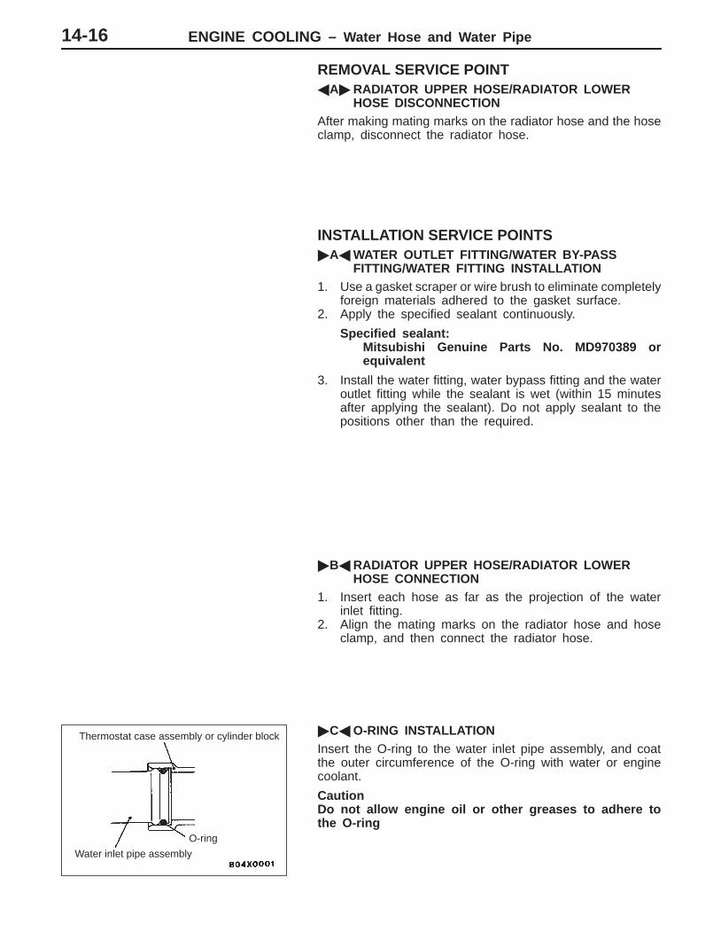
REMOVAL SERVICE POINT�A�RADIATOR UPPER HOSE/RADIATOR LOWER
HOSE DISCONNECTIONAfter making mating marks on the radiator hose and the hoseclamp, disconnect the radiator hose.
INSTALLATION SERVICE POINTS�A�WATER OUTLET FITTING/WATER BY-PASS
FITTING/WATER FITTING INSTALLATION1. Use a gasket scraper or wire brush to eliminate completely
foreign materials adhered to the gasket surface.2. Apply the specified sealant continuously.
Specified sealant:Mitsubishi Genuine Parts No. MD970389 orequivalent
3. Install the water fitting, water bypass fitting and the wateroutlet fitting while the sealant is wet (within 15 minutesafter applying the sealant). Do not apply sealant to thepositions other than the required.
�B�RADIATOR UPPER HOSE/RADIATOR LOWERHOSE CONNECTION
1. Insert each hose as far as the projection of the waterinlet fitting.
2. Align the mating marks on the radiator hose and hoseclamp, and then connect the radiator hose.
�C�O-RING INSTALLATIONInsert the O-ring to the water inlet pipe assembly, and coatthe outer circumference of the O-ring with water or enginecoolant.
CautionDo not allow engine oil or other greases to adhere tothe O-ring
Thermostat case assembly or cylinder block
O-ring
Water inlet pipe assembly

ENGINE COOLING – Water Hose and Water Pipe 14-17
INSPECTIONWATER PIPE AND HOSE CHECKCheck the water pipe and hose for cracks, damage, clog andreplace them if necessary.
ENGINE COOLING – Radiator14-18
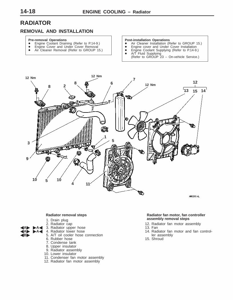
RADIATORREMOVAL AND INSTALLATION
Pre-removal Operations� Engine Coolant Draining (Refer to P.14-9.)� Engine Cover and Under Cover Removal� Air Cleaner Removal (Refer to GROUP 15.)
Post-installation Operations� Air Cleaner Installation (Refer to GROUP 15.)� Engine cover and Under Cover Installation� Engine Coolant Supplying (Refer to P.14-9.)� A/T Fluid Supplying
(Refer to GROUP 23 – On-vehicle Service.)
3
1
12 Nm 12 Nm
12 Nm8 28
7
13 15 14
12
5
4 11
6
5 1010
9
Radiator removal steps1. Drain plug2. Radiator cap
�A� �A� 3. Radiator upper hose�A� �A� 4. Radiator lower hose�B� 5. A/T oil cooler hose connection
6. Rubber hose7. Condense tank8. Upper insulator9. Radiator assembly
10. Lower insulator11. Condenser fan motor assembly12. Radiator fan motor assembly
Radiator fan motor, fan controllerassembly removal steps
12. Radiator fan motor assembly13. Fan14. Radiator fan motor and fan control-
ler assembly15. Shroud

ENGINE COOLING – Radiator 14-19
REMOVAL SERVICE POINTS�A�RADIATOR UPPER HOSE/RADIATOR LOWER
HOSE DISCONNECTIONAfter making mating marks on the radiator hose and the hoseclamp, disconnect the radiator hose.
�B�A/T OIL COOLER HOSE REMOVALAfter removing the hose from the radiator, plug the hose andthe radiator nipple to prevent dust or foreign particles fromgetting in.
INSTALLATION SERVICE POINT�A�RADIATOR LOWER HOSE/RADIATOR UPPER
HOSE CONNECTION1. Insert each hose as far as the projection of the water
inlet fitting.2. Align the mating marks on the radiator hose and hose
clamp, and then connect the radiator hose.

NOTES

ENGINE COOLING – General/Water Hose and Water Pipe 14-1
GROUP 14
ENGINE COOLINGGENERALOUTLINE OF CHANGESThe following service procedures have been established due to the addition of vehicles with 4G9-MPI engine.Other service procedures are the same as the vehicles with GDI engine.
WATER HOSE AND WATER PIPEREMOVAL AND INSTALLATION
Pre-removal and Post-installation Operation� Engine Coolant Draining and Suppling� Air Cleaner Removal and Installation
(Refer to GROUP 15.)
� Exhaust Manifold Removal and Installation(Refer to GROUP 15.)
1
23
4
5
6
7
8
9
10
11
12
1314
9
9
4
10
24 ± 1 N·m
24 ± 1 N·m
14 ± 1 N·m
24 ± 1 N·m
24 ± 1 N·m
24 ± 1 N·m
14 ± 1 N·m
Removal steps1. Radiator lower hose connection2. Thermostat case assembly3. Water pipe4. O-ring5. Water fitting6. Heater hose connection7. Water pipe assembly
8. Water by-pass fitting9. O-ring
10. Water hose11. Water pipe12. Water hose13. Radiator upper hose connection14. Water outlet fitting

ENGINE COOLING – Radiator14-2
RADIATORREMOVAL AND INSTALLATION
Pre-removal Operations� Engine Coolant Draining� Engine Cover and Under Cover Removal� Air Cleaner Removal
Post-installation Operations� Air Cleaner Installation� Engine Cover and Under Cover Installation� Engine Coolant Supplying� A/T Fluid Supplying
3
1
8 28
7
1315
14
12
5
411
6
5
10
10
9
12 ± 2 N·m
12 ± 2 N·m
12 ± 2 N·m
Radiator removal steps1. Drain plug2. Radiator cap3. Radiator upper hose4. Radiator lower hose5. A/T oil cooler hose connection6. Rubber hose7. Condense tank8. Upper insulator9. Radiator assembly
10. Lower insulator11. Condenser fan motor assembly12. Radiator fan motor assembly
Radiator fan motor assembly removalsteps
12. Radiator fan motor assembly13. Fan14. Radiator fan motor15. Shroud
ENGINE COOLING – Radiator 14-3
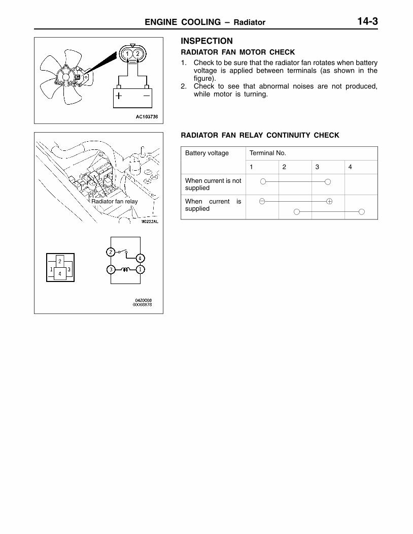
INSPECTIONRADIATOR FAN MOTOR CHECK1. Check to be sure that the radiator fan rotates when battery
voltage is applied between terminals (as shown in thefigure).
2. Check to see that abnormal noises are not produced,while motor is turning.
RADIATOR FAN RELAY CONTINUITY CHECK
Battery voltage Terminal No.
1 2 3 4
When current is notsupplied
When current issupplied
Radiator fan relay

NOTES