14. test generation algorithms and emulation for veri cation
TRANSCRIPT
Verification of Digital Systems, Spring 202014. Test Generation Algorithms and Emulation for Verification 1
14. Test Generation Algorithms and Emulation forVerification
Jacob Abraham
Department of Electrical and Computer EngineeringThe University of Texas at Austin
Verification of Digital SystemsSpring 2020
March 5, 2020
ECE Department, University of Texas at AustinLecture 14. Test Generation Algorithms and
Emulation for Verification Jacob Abraham, March 5, 2020 1 / 41
Manufacturing Test
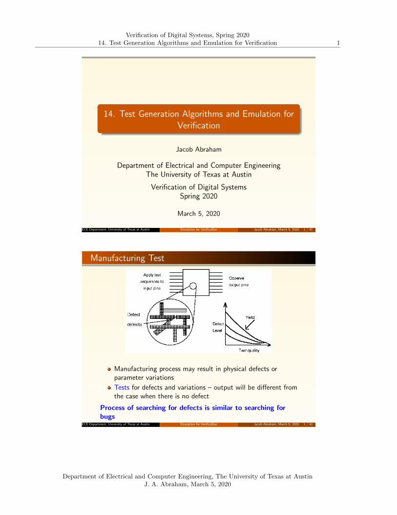
Manufacturing process may result in physical defects orparameter variations
Tests for defects and variations – output will be different fromthe case when there is no defect
Process of searching for defects is similar to searching forbugs
ECE Department, University of Texas at AustinLecture 14. Test Generation Algorithms and
Emulation for Verification Jacob Abraham, March 5, 2020 1 / 41
Department of Electrical and Computer Engineering, The University of Texas at AustinJ. A. Abraham, March 5, 2020

Verification of Digital Systems, Spring 202014. Test Generation Algorithms and Emulation for Verification 2
Tests for Faults in a Circuit
Approach to generating tests for defects is to map defects to(higher level) faults: develop fault model, then generate testsfor the faults
Typical for defects: gate-level “stuck-at” fault modelFor bugs: Line coverage, control state coverage, “coveragepoints”, etc.
As technology shrinks, other physical faults: bridging faults,delay faults, crosstalk faults, etc.
Some electrical faults (due to design or manufacturing) areonly seen in post-silicon validation
An interesting point: what is important is how well the testsgenerated (based on the fault model) will detect realisticdefects or bugs
The accuracy of the fault model is secondary
ECE Department, University of Texas at AustinLecture 14. Test Generation Algorithms and
Emulation for Verification Jacob Abraham, March 5, 2020 2 / 41
Automatic Test Pattern Generation (ATPG)
Map defects to (higher level) faults, and develop fault models(example logic-level “stuck-at” faults, or “path delay” faults)
Steps in Test Generation
Activate fault (produce error at fault site)
“Sensitize” path from fault to output (propagate error tooutput)
“Justify” internal signals to primary inputs
Choices may exist during sensitization and justification: ifconflicts arise, need to backtrack
If no test exists, fault is redundant
SAT solvers have been applied to generating tests forcombinational blocksPropagation of the error is not necessary for verification (anynode can be monitored in simulation)
ECE Department, University of Texas at AustinLecture 14. Test Generation Algorithms and
Emulation for Verification Jacob Abraham, March 5, 2020 3 / 41
Department of Electrical and Computer Engineering, The University of Texas at AustinJ. A. Abraham, March 5, 2020

Verification of Digital Systems, Spring 202014. Test Generation Algorithms and Emulation for Verification 3
ATPG Complexity
Problem of generating a test for a stuck-at-fault in acombinational circuit is NP-Complete
Satisfiability is also NP-Complete
A lot of interesting problems belong to the class of NP-Completeproblems
Tovey, Craig A, “Tutorial on computational complexity,”,INFORMS Journal on Applied Analytics, vol. 32, pp. 30–61,2002.
Classic paper by Karp: Karp R .M., “Reducibility amongCombinatorial Problems,” In: Miller R. E., Thatcher J.W.,Bohlinger J.D. (eds) Complexity of Computer Computations,The IBM Research Symposia Series, 1972, Springer, Boston,MA.
ECE Department, University of Texas at AustinLecture 14. Test Generation Algorithms and
Emulation for Verification Jacob Abraham, March 5, 2020 4 / 41
Observability and Controllability
Observability: ease of observing a value on a node bymonitoring external output pins of the chip
Controllability: ease of forcing a node to 0 or 1 by drivinginput pins of the chip
Combinational logic is usually easier to observe and control
Still, NP-complete problem
Finite state machines can be very difficult, requiring manycycles to enter desired state
Especially if state transition diagram is not known to the testengineer, or is too large
ECE Department, University of Texas at AustinLecture 14. Test Generation Algorithms and
Emulation for Verification Jacob Abraham, March 5, 2020 5 / 41
Department of Electrical and Computer Engineering, The University of Texas at AustinJ. A. Abraham, March 5, 2020
Verification of Digital Systems, Spring 202014. Test Generation Algorithms and Emulation for Verification 4
Sequential Circuit Test Generation
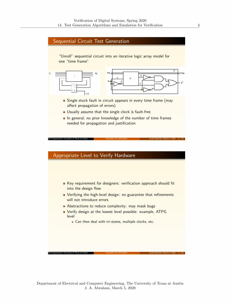
“Unroll” sequential circuit into an iterative logic array model forone “time frame”
Single stuck fault in circuit appears in every time frame (mayaffect propagation of errors)
Usually assume that the single clock is fault-free
In general, no prior knowledge of the number of time framesneeded for propagation and justification
ECE Department, University of Texas at AustinLecture 14. Test Generation Algorithms and
Emulation for Verification Jacob Abraham, March 5, 2020 6 / 41
Appropriate Level to Verify Hardware
Key requirement for designers: verification approach should fitinto the design flow
Verifying the high-level design: no guarantee that refinementswill not introduce errors
Abstractions to reduce complexity: may mask bugs
Verify design at the lowest level possible: example, ATPGlevel
Can then deal with tri-states, multiple clocks, etc.
ECE Department, University of Texas at AustinLecture 14. Test Generation Algorithms and
Emulation for Verification Jacob Abraham, March 5, 2020 7 / 41
Department of Electrical and Computer Engineering, The University of Texas at AustinJ. A. Abraham, March 5, 2020
Verification of Digital Systems, Spring 202014. Test Generation Algorithms and Emulation for Verification 5
Test Generation Algorithms for Verification
Testing and verification constraints
Limited observability inside a chip during manufacturing test
Pre-silicon verification can take advantage of a high degree ofobservability (not necessary to propagate errors to chipoutputs or scan flip-flops during verification)
Testing versus verification
Activating a test for a fault on a node (say x stuck-at-0)means that a test sequence should result in a 1 on x
This sequence is a witness to the property Fx
To find a sequence which will prove that a state si iseventually reached (i.e., Fsi), we test for a stuck-at-0 on anAND gate with the appropriate state variable inputs
ECE Department, University of Texas at AustinLecture 14. Test Generation Algorithms and
Emulation for Verification Jacob Abraham, March 5, 2020 8 / 41
Functional Test Generation
Attempt to generate tests when detailed structuralinformation is not available, or for extremely complex systems
Useful for verification and speed tests
Requirement for successful functional test:Check for unintended functions in addition to the correct onePhysical failures can cause spurious operations whileperforming the desired function correctlyAd-hoc functional tests typically do not check for such behavior
Applied to generating tests for memories, microprocessors
ECE Department, University of Texas at AustinLecture 14. Test Generation Algorithms and
Emulation for Verification Jacob Abraham, March 5, 2020 9 / 41
Department of Electrical and Computer Engineering, The University of Texas at AustinJ. A. Abraham, March 5, 2020

Verification of Digital Systems, Spring 202014. Test Generation Algorithms and Emulation for Verification 6
Functional Fault Model for Memories
Memory Arrays
One or more cells become stuck at 1 or 0
One or more cells fail to undergo a 0 to 1 or a 1 to 0 transition
There exist two (or more) cells which are coupledA 0 to 1 (or a 1 to 0) transition in a cell (due to a write inthat cell) changes the contents of another cell from 0 to 1 orfrom 1 to 0If transition in cell I changes J, transition in J may not affectthe state of cell I
Multiple cells accessed during READ or WRITE
ECE Department, University of Texas at AustinLecture 14. Test Generation Algorithms and
Emulation for Verification Jacob Abraham, March 5, 2020 10 / 41
Memory Fault Model, Cont’d
Decoders
The decoder will not access the addressed cell, and in additionmay access non-addressed cells
The decoder will access multiple cells, including the addressedcell
Assumption that the combinational logic of the decoder willnot be transformed into sequential logic
Decoder faults look like memory cell array faults
Fault model can be validated by simulating effects of faults atthe transistor level
ECE Department, University of Texas at AustinLecture 14. Test Generation Algorithms and
Emulation for Verification Jacob Abraham, March 5, 2020 11 / 41
Department of Electrical and Computer Engineering, The University of Texas at AustinJ. A. Abraham, March 5, 2020

Verification of Digital Systems, Spring 202014. Test Generation Algorithms and Emulation for Verification 7
Example “March” Test for Memories
R: Read cell and verifyC: Complement cell
Complexity of Test: 14N (N cells)
This test will verify that writing any location will not disturbany other location
ECE Department, University of Texas at AustinLecture 14. Test Generation Algorithms and
Emulation for Verification Jacob Abraham, March 5, 2020 12 / 41
Functional Testing of Microprocessors
Developed in the 80s for generating tests based oninformation about the instruction set
Tests for vendor parts without knowing details
Tests based on “functional fault models” derived fromanalysis of the effects of low level faults on the behavior ofmodules
Based on functional tests for memories
Fault models at control sequencing level
Tests based on high-level information can also be used forvalidating design correctness
ECE Department, University of Texas at AustinLecture 14. Test Generation Algorithms and
Emulation for Verification Jacob Abraham, March 5, 2020 13 / 41
Department of Electrical and Computer Engineering, The University of Texas at AustinJ. A. Abraham, March 5, 2020

Verification of Digital Systems, Spring 202014. Test Generation Algorithms and Emulation for Verification 8
Data Storage and Transfer Tests0000000000000000000000000000000011111111111111111111111111111111
0000000000000000111111111111111111111111111111110000000000000000
0000000011111111000000001111111111111111000000001111111100000000
0000111100001111000011110000111111110000111100001111000011110000
0011001100110011001100110011001111001100110011001100110011001100
0101010101010101010101010101010110101010101010101010101010101010
Data patterns to check alllogical paths and all registers(32-bit transfer path)
Test length logarithmic in number of bits (divide and conquer)Will such tests verify that there is no interaction between linesin a data path?
ECE Department, University of Texas at AustinLecture 14. Test Generation Algorithms and
Emulation for Verification Jacob Abraham, March 5, 2020 14 / 41
Automatic Functional Test Generation for an ISAShen, 1998–99
ECE Department, University of Texas at AustinLecture 14. Test Generation Algorithms and
Emulation for Verification Jacob Abraham, March 5, 2020 15 / 41
Department of Electrical and Computer Engineering, The University of Texas at AustinJ. A. Abraham, March 5, 2020
Verification of Digital Systems, Spring 202014. Test Generation Algorithms and Emulation for Verification 9
Tests for Superscalar Processors
Test various mechanisms
Branch prediction
Exception and misprediction recovery
Data dependency solutions
Pipeline seelction (instruction pairing)
In addition
Monitor performance
ECE Department, University of Texas at AustinLecture 14. Test Generation Algorithms and
Emulation for Verification Jacob Abraham, March 5, 2020 16 / 41
Improving Tests Through Genetic LearningSaab, 1994
Approach
Partition circuit
Depth first search
Run tests
Pick regions with very low activity
Create activity
Approach – Genetic Algorithm
Reproduction (copying potentially useful candidate vectorsand sequences)
Mutation (flipping bits in a vector).
Splicing (producing a new vector using substrings from twoother vectors)
Splicing (producing a new sequence using subsequence fromtwo sequences)
ECE Department, University of Texas at AustinLecture 14. Test Generation Algorithms and
Emulation for Verification Jacob Abraham, March 5, 2020 17 / 41
Department of Electrical and Computer Engineering, The University of Texas at AustinJ. A. Abraham, March 5, 2020

Verification of Digital Systems, Spring 202014. Test Generation Algorithms and Emulation for Verification 10
Genetic Algorithm
Found to be fast and efficient
Can be used for very large circuits
Applicable to different levels – RTL, gate, transistor
ECE Department, University of Texas at AustinLecture 14. Test Generation Algorithms and
Emulation for Verification Jacob Abraham, March 5, 2020 18 / 41
Verifying Properties Using Sequential ATPG
Prior work in checking safety properties; required custom ATPG ormodifications to existing ATPG tools
Detecting a “stuck-at-0” fault on p is equivalent to proving EFp
ECE Department, University of Texas at AustinLecture 14. Test Generation Algorithms and
Emulation for Verification Jacob Abraham, March 5, 2020 19 / 41
Department of Electrical and Computer Engineering, The University of Texas at AustinJ. A. Abraham, March 5, 2020

Verification of Digital Systems, Spring 202014. Test Generation Algorithms and Emulation for Verification 11
Approach to Property Checking
Abraham, Vedula and Saab, 2002
Bounded Model Checking
ECE Department, University of Texas at AustinLecture 14. Test Generation Algorithms and
Emulation for Verification Jacob Abraham, March 5, 2020 20 / 41
Monitor State Machine for EXp
The monitor machine moves to an accepting state if p is true
This is combined with the design, and the ATPG tool asked to findan input sequence to reach the state “n”
The result would be one of
ATPG finds an input sequence – EXp is proved, and thesequence would be a witness to the property
ATPG returns the result that a “test” is not possible – EXp isfalse
ATPG aborts – the design was too complex to be analyzed
ECE Department, University of Texas at AustinLecture 14. Test Generation Algorithms and
Emulation for Verification Jacob Abraham, March 5, 2020 21 / 41
Department of Electrical and Computer Engineering, The University of Texas at AustinJ. A. Abraham, March 5, 2020

Verification of Digital Systems, Spring 202014. Test Generation Algorithms and Emulation for Verification 12
Checking EGp
Find an input sequence of length n for which the system will satisfythe property p
Bounded Liveness
If there is a loop back from state n to the starting state, we candeduce general liveness
ECE Department, University of Texas at AustinLecture 14. Test Generation Algorithms and
Emulation for Verification Jacob Abraham, March 5, 2020 22 / 41
Checking E pUq
For some path of up to n cycles, there is a state where q holds,and p holds in every previous state
ECE Department, University of Texas at AustinLecture 14. Test Generation Algorithms and
Emulation for Verification Jacob Abraham, March 5, 2020 23 / 41
Department of Electrical and Computer Engineering, The University of Texas at AustinJ. A. Abraham, March 5, 2020
Verification of Digital Systems, Spring 202014. Test Generation Algorithms and Emulation for Verification 13
Results on ISCAS89 Benchmark Circuits
ATPG: commercial tool (Mentor flextest)
BMC: Cadence research tool (SMV) with zchaff SAT solver
s838.1 – 36 inputs, 1 output, 446 gates, 32 flops
Property: output is 1 for a sequence of n clocks (n=5, 10, 15)
Result: true for n = 5, 10 (false for n = 15)
CPU seconds to check property(SUN UltraSparc, dual 450MHz, 1 GByte)
Bound: 5 Bound: 10 Bound: 15
BMC ATPG BMC ATPG BMC ATPG
1.57 0.1 2.0 0.2 2.88 0.3
ECE Department, University of Texas at AustinLecture 14. Test Generation Algorithms and
Emulation for Verification Jacob Abraham, March 5, 2020 24 / 41
Checking Properties of GL85
Clone of Intel 8085 designed by Alex Miczo (notpin-compatible)
10,084 gates, 238 flip-flops
Properties (dealing with system reset)
ROIA: Reset on Interrupt AcknowledgeRORW: Reset on Read-WriteROTF: Reset on Tstates FlowROIE: Reset on Interrupt EnableTOPE: Trap on Priority EncodingRWIO: Reset While Interrupt On
Example:G((TRAP = 1 & TRAPFF = 1) =⇒ (P5/PIE(2 : 0) =000B))
ECE Department, University of Texas at AustinLecture 14. Test Generation Algorithms and
Emulation for Verification Jacob Abraham, March 5, 2020 25 / 41
Department of Electrical and Computer Engineering, The University of Texas at AustinJ. A. Abraham, March 5, 2020

Verification of Digital Systems, Spring 202014. Test Generation Algorithms and Emulation for Verification 14
Time for Checking GL85 Properties
CPU seconds on SUN UltraSparc, dual 450MHz, 1 GByte
Bound = 25
Property BMC ATPG
RORW 7209 12.1
ROTF 4373 12.4
ROIA 6589 12.8
ROIE 7072 13.8
TOPE 10156 13.2
RWIO 6669 12.3
ECE Department, University of Texas at AustinLecture 14. Test Generation Algorithms and
Emulation for Verification Jacob Abraham, March 5, 2020 26 / 41
ATPG State Justification
ATPG activates the monitor faults in the last time frame
Justify the activation state from unknown on known initialstate
ECE Department, University of Texas at AustinLecture 14. Test Generation Algorithms and
Emulation for Verification Jacob Abraham, March 5, 2020 27 / 41
Department of Electrical and Computer Engineering, The University of Texas at AustinJ. A. Abraham, March 5, 2020
Verification of Digital Systems, Spring 202014. Test Generation Algorithms and Emulation for Verification 15
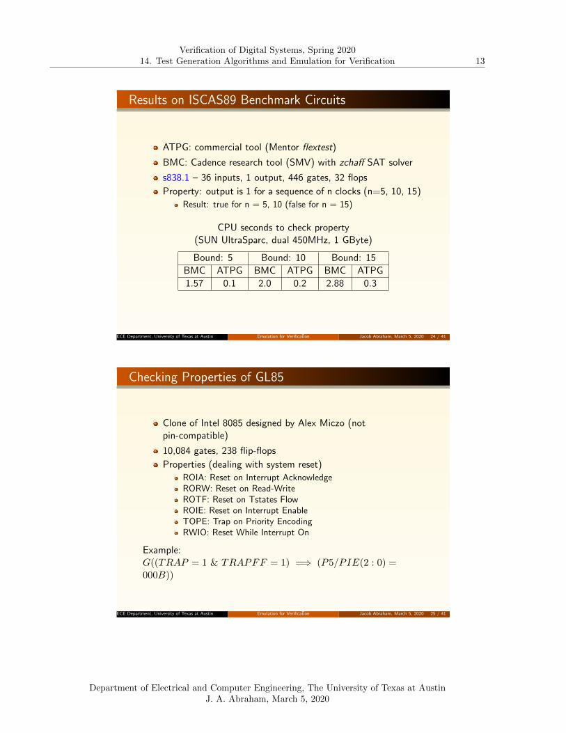
ATPG Model for EF(p)
EF(p) is valid if fault at line EF(p) stuck-at-1 is redundant
The fault is at the primary output; only fault-free values need tobe justified
ECE Department, University of Texas at AustinLecture 14. Test Generation Algorithms and
Emulation for Verification Jacob Abraham, March 5, 2020 28 / 41
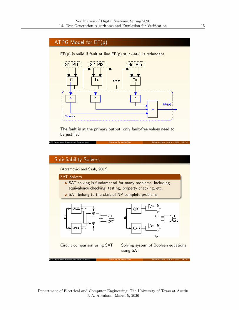
Satisfiability Solvers
(Abramovici and Saab, 2007)
SAT Solvers
SAT solving is fundamental for many problems, includingequivalence checking, testing, property checking, etc.
SAT belong to the class of NP-complete problems
Circuit comparison using SAT Solving system of Boolean equationsusing SAT
ECE Department, University of Texas at AustinLecture 14. Test Generation Algorithms and
Emulation for Verification Jacob Abraham, March 5, 2020 29 / 41
Department of Electrical and Computer Engineering, The University of Texas at AustinJ. A. Abraham, March 5, 2020
Verification of Digital Systems, Spring 202014. Test Generation Algorithms and Emulation for Verification 16
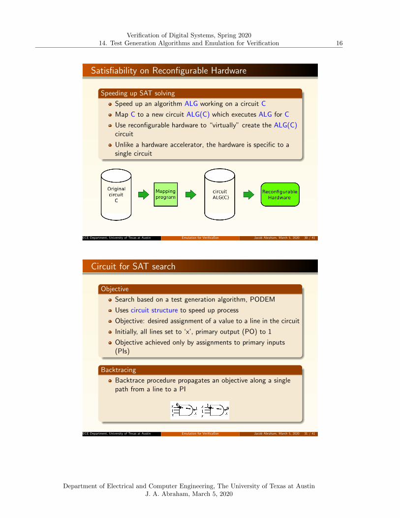
Satisfiability on Reconfigurable Hardware
Speeding up SAT solving
Speed up an algorithm ALG working on a circuit C
Map C to a new circuit ALG(C) which executes ALG for C
Use reconfigurable hardware to “virtually” create the ALG(C)circuit
Unlike a hardware accelerator, the hardware is specific to asingle circuit
ECE Department, University of Texas at AustinLecture 14. Test Generation Algorithms and
Emulation for Verification Jacob Abraham, March 5, 2020 30 / 41
Circuit for SAT search
Objective
Search based on a test generation algorithm, PODEM
Uses circuit structure to speed up process
Objective: desired assignment of a value to a line in the circuit
Initially, all lines set to ‘x’, primary output (PO) to 1
Objective achieved only by assignments to primary inputs(PIs)
Backtracing
Backtrace procedure propagates an objective along a singlepath from a line to a PI
ECE Department, University of Texas at AustinLecture 14. Test Generation Algorithms and
Emulation for Verification Jacob Abraham, March 5, 2020 31 / 41
Department of Electrical and Computer Engineering, The University of Texas at AustinJ. A. Abraham, March 5, 2020
Verification of Digital Systems, Spring 202014. Test Generation Algorithms and Emulation for Verification 17
Flowchart of Search Algorithm
ECE Department, University of Texas at AustinLecture 14. Test Generation Algorithms and
Emulation for Verification Jacob Abraham, March 5, 2020 32 / 41
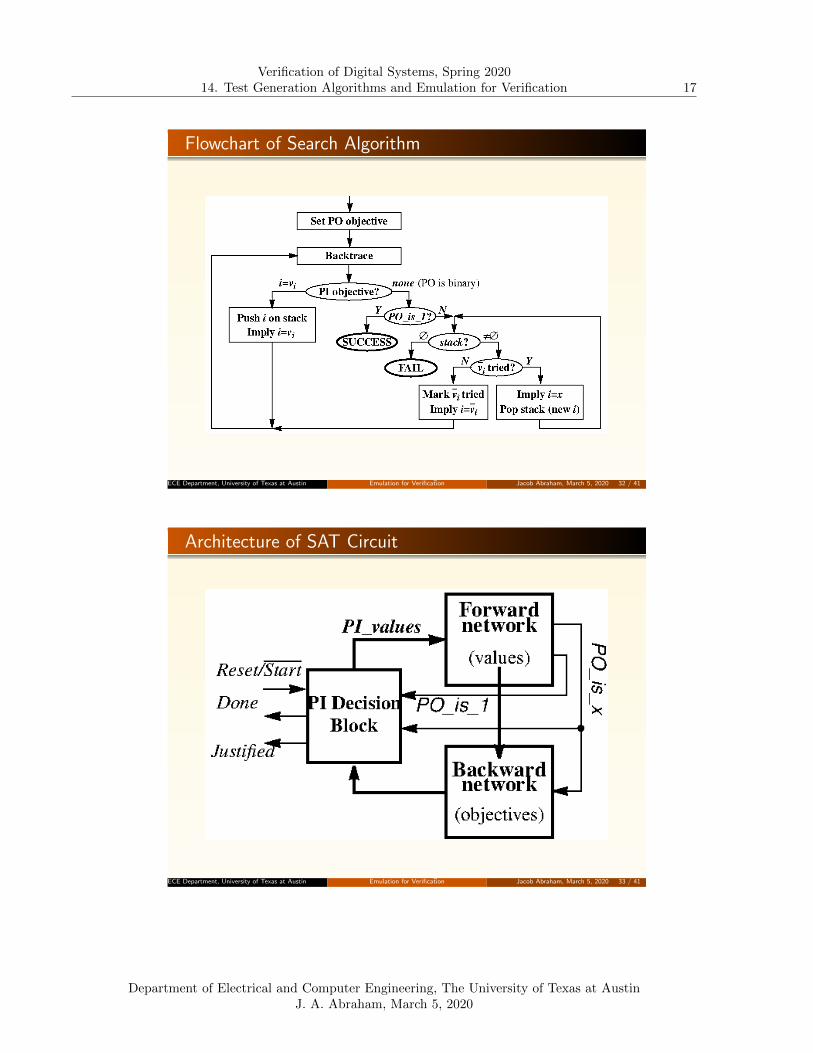
Architecture of SAT Circuit
ECE Department, University of Texas at AustinLecture 14. Test Generation Algorithms and
Emulation for Verification Jacob Abraham, March 5, 2020 33 / 41
Department of Electrical and Computer Engineering, The University of Texas at AustinJ. A. Abraham, March 5, 2020
Verification of Digital Systems, Spring 202014. Test Generation Algorithms and Emulation for Verification 18
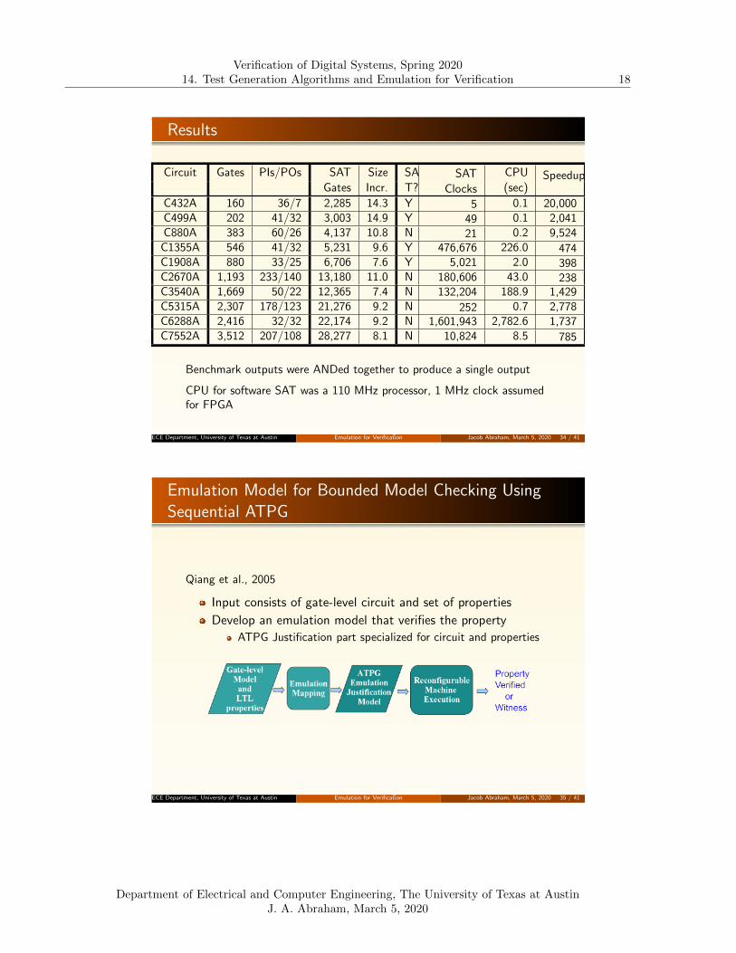
Results
Circuit Gates PIs/POs SAT Size SA SAT CPU SpeedupGates Incr. T? Clocks (sec)
C432A 160 36/7 2,285 14.3 Y 5 0.1 20,000C499A 202 41/32 3,003 14.9 Y 49 0.1 2,041C880A 383 60/26 4,137 10.8 N 21 0.2 9,524
C1355A 546 41/32 5,231 9.6 Y 476,676 226.0 474C1908A 880 33/25 6,706 7.6 Y 5,021 2.0 398C2670A 1,193 233/140 13,180 11.0 N 180,606 43.0 238C3540A 1,669 50/22 12,365 7.4 N 132,204 188.9 1,429C5315A 2,307 178/123 21,276 9.2 N 252 0.7 2,778C6288A 2,416 32/32 22,174 9.2 N 1,601,943 2,782.6 1,737C7552A 3,512 207/108 28,277 8.1 N 10,824 8.5 785
Benchmark outputs were ANDed together to produce a single output
CPU for software SAT was a 110 MHz processor, 1 MHz clock assumedfor FPGA
ECE Department, University of Texas at AustinLecture 14. Test Generation Algorithms and
Emulation for Verification Jacob Abraham, March 5, 2020 34 / 41
Emulation Model for Bounded Model Checking UsingSequential ATPG
Qiang et al., 2005
Input consists of gate-level circuit and set of properties
Develop an emulation model that verifies the property
ATPG Justification part specialized for circuit and properties
ECE Department, University of Texas at AustinLecture 14. Test Generation Algorithms and
Emulation for Verification Jacob Abraham, March 5, 2020 35 / 41
Department of Electrical and Computer Engineering, The University of Texas at AustinJ. A. Abraham, March 5, 2020

Verification of Digital Systems, Spring 202014. Test Generation Algorithms and Emulation for Verification 19
Emulation Architecture
ECE Department, University of Texas at AustinLecture 14. Test Generation Algorithms and
Emulation for Verification Jacob Abraham, March 5, 2020 36 / 41
Model Sizes of ISCAS89 Circuits
Original Model ATPG ModelCircuit PIs POs PPIs Gates Gates Increase
s1238 14 14 18 508 16011 30.5s1423 17 5 74 657 17690 25.9s1488 8 19 6 653 16327 24.0s1494 8 19 6 647 16365 24.3s5378 35 49 179 2779 30862 10.1s9234 36 39 211 5597 42430 6.6s13207 62 152 638 7951 63437 7.0s15850 77 150 534 9772 67855 5.9s35932 35 320 1728 16065 162415 9.1s38417 28 106 1636 22179 143977 5.5s38584 38 304 1426 19253 159249 7.3
2 – 3 orders of magnitude speedup over software by usingemulation hardware
ECE Department, University of Texas at AustinLecture 14. Test Generation Algorithms and
Emulation for Verification Jacob Abraham, March 5, 2020 37 / 41
Department of Electrical and Computer Engineering, The University of Texas at AustinJ. A. Abraham, March 5, 2020

Verification of Digital Systems, Spring 202014. Test Generation Algorithms and Emulation for Verification 20
When Should Emulation be Used for Verification?
Source: L. Rizzatti, “10 Best Verification Practices for Hardware Emulation”,
Electronic Design, June 29, 2016
ECE Department, University of Texas at AustinLecture 14. Test Generation Algorithms and
Emulation for Verification Jacob Abraham, March 5, 2020 38 / 41
Synopsys Emulation (ZeBu)
ECE Department, University of Texas at AustinLecture 14. Test Generation Algorithms and
Emulation for Verification Jacob Abraham, March 5, 2020 39 / 41
Department of Electrical and Computer Engineering, The University of Texas at AustinJ. A. Abraham, March 5, 2020

Verification of Digital Systems, Spring 202014. Test Generation Algorithms and Emulation for Verification 21
Cadence Special-Purpose Emulator (Palladium)
ECE Department, University of Texas at AustinLecture 14. Test Generation Algorithms and
Emulation for Verification Jacob Abraham, March 5, 2020 40 / 41
Mentor Emulation (Veloce)
ECE Department, University of Texas at AustinLecture 14. Test Generation Algorithms and
Emulation for Verification Jacob Abraham, March 5, 2020 41 / 41
Department of Electrical and Computer Engineering, The University of Texas at AustinJ. A. Abraham, March 5, 2020