1.4 work covered by contract documents
TRANSCRIPT

1.4 WORK COVERED BY CONTRACT DOCUMENTS
A. Type of Contract:
1. Project will be constructed under a single prime contract.
B. The Work of Project is defined by the Contract Documents and consists generally of the
following:
1. Selective demolition and renovation of existing toilet rooms and related spaces with toilet
and shower facilities for the purposes of complying with the Americans with Disabilities Act.
2. Renovations to existing pedestrian horizontal and vertical circulation to create accessible routes to upgraded restrooms.
3. Scope of work includes delegated design services provided by the Contractor to achieve the indicated renovations for the following:
a. Renovation and improvement of HVAC air circulation systems b. Renovation and improvement of plumbing systems c. Rerouting and modification of existing utilities to accommodate new work d. Renovation and improvement of fire suppression and fire safety and
communications systems
4. New and renovated Mechanical, Electrical and Plumbing are design-build in accordance
with but not necessarily limited to the requirements indicated. Delegated design includes the sizing, routing and placement of utility and mechanical services as wholly new, or extensions of existing services in order to comply with Authorities Having Jurisdiction.
5. Renovations occur in multiple schools and multiple locations within schools as indicated in the Contract Documents.
6. Refer to the Contract Documents for additional information, with common work for all spaces generally as follows:
a. Demolition of existing masonry and lightweight partitions within existing rooms and
spaces. b. Removal of all existing fixtures, fittings and plumbing service not indicated to
remain. Selected salvage and return to Owner as indicated. c. Removal of all toilet accessories. Selected salvage and return to Owner as
indicated. d. Removal of existing flooring, trenching for new work, and concrete patching and/or
cement underlayment to re-level modified existing substrates. e. Relocation of existing utilities and services to fit new and relocated mechanical
chases. f. Removal of existing doors and frames.

g. New finishes include epoxy floor systems, resilient tile, and wall tile. Ceilings are
generally repainted exposed structure, suspended gypsum board, and acoustical panel ceilings and soffits.
h. Fit out includes all new toilet fixtures, fittings, lighting and air circulation services, including new toilet compartments and toilet, shower, and janitorial accessories.
i. Remodeling openings for accessibility include new hollow metal frames and flush wood doors.
j. Paints and coatings include acryclic latex and epoxy paints, with anti-graffiti treatments for wall finishes, and moisture transmission vapor control coatings for concrete.
k. Fire suppression and fire safety devices are new and existing relocated devices with new wired communication to central fire control systems.
1.5 WORK BY OWNER
A. General: Cooperate fully with Owner so work may be carried out smoothly, without interfering
with or delaying work under this Contract or work by Owner. Coordinate the Work of this Contract with work performed by Owner.
B. Preceding Work: Owner will perform the following construction operations at Project site.
Those operations are scheduled to be substantially complete(or non-intrusive) before work under this Contract begins.
1. Hazardous Material Abatement (Abatement Contractor may be on site once contractor
mobilizes, but work will be limited to attic ductwork cleaning, and should not interrupt general demolition in main auditorium)
1.6 OWNER-FURNISHED PRODUCTS
A. Owner will furnish only those products indicated. The Work includes the Contractor
receiving, unloading, handling, storing, protecting, and installing Owner-furnished products
1.7 ACCESS TO SITE
A. General: Contractor shall have limited use of Project site for construction operations as
indicated by the Contract limits.
B. It is the intention of this contract to perform the work during summer hours when school is not in
session and students are not typically present. Owner may, at his discretion, allow summer programs in other portions of the building. Contractor to maintain strict controls on site between work areas and any student activity, inside or exterior to the buildings.
C. Use of Site: Limit use of Project site to work in areas indicated. Do not disturb portions of
project site beyond areas in which the work is indicated.
1. Limits: Confine construction operations to areas of construction 2. Do not allow contractor’s disposal or delivery paths through the building to cross or occur
directly adjacent to any Owner occupied spaces where students may be present during summer hours.
3. Driveways, Walkways and Entrances: Keep driveways, loading areas, and entrances serving premises clear and available to Owner, Owner's employees, and emergency vehicles at all times. Do not use these areas for parking or storage of materials.

a. Schedule deliveries to minimize use of driveways and entrances by construction operations.
b. Schedule deliveries to minimize space and time requirements for storage of materials and equipment on-site.
D. Condition of Existing Building: Maintain portions of existing building affected by construction
operations in a weather-tight condition throughout construction period. Repair damage caused by construction operations to the owners satisfaction.
E. Maintain existing exit-ways for emergency egress.
1.8 COORDINATION WITH OCCUPANTS
A. Partial Owner Occupancy: Owner m ay occupy the premises during the entire construction
period, with the exception of areas under construction. Cooperate with Owner during construction operations to minimize conflicts and facilitate Owner usage. Perform the Work so as not to interfere with Owner's operations. Maintain existing exits unless otherwise indicated.
1. Maintain access to existing walkways, corridors, and other adjacent occupied or used
facilities. Do not close or obstruct walkways, corridors, or other occupied or used facilities without written permission from Owner and authorities having jurisdiction.
2. Provide not less than 48 (forty eight) hours' notice to Owner of activities that will affect Owner's operations.
1.9 WORK RESTRICTIONS
A. Work Restrictions, General:
1. Comply with limitations on use of public streets and with other requirements of authorities
having jurisdiction.
B. On-Site Work Hours:
1. Day shift during summer and unoccupied times 2. Weekend Hours: Unlimited 3. Utility Shutdowns: As coordinated with Owner 4. Hours for Core Drilling and other noisy activity: Second Shift when building is occupied by students or staff
C. Existing Utility Interruptions: Do not interrupt utilities serving facilities occupied by Owner or
others unless permitted under the following conditions and then only after providing temporary utility services according to requirements indicated:
1. Notify Owner not less than (4) four days in advance of proposed utility interruptions. 2. Obtain Owner's written permission before proceeding with utility interruptions.
D. Structural loading of Existing Floors:
1. Demolition work, new work and staging of materials and equipment shall be limited to a
maximum imposed loading of 100 psf at any existing floor system, both concentrated and uniformly distributed loading.

E. Noise, Vibration, and Odors: Coordinate operations that may result in high levels of noise and vibration, odors, or other disruption to occupants.
1. Notify Owner not less than two (2) days in advance of proposed disruptive operations. 2. Obtain Owner’s written permission before proceeding with disruptive operations.
F. Nonsmoking School Zone: Smoking is not permitted anywhere on School Property.
G. Controlled Substances: Use of tobacco products and other controlled substances within the on
Project site is not permitted.
H. Coordinate Employee Identification Requirements with Owner
I. Employee Screening: Comply with Owner screening requirements for drug and background
screening of Contractor personnel working on Project site.
1. Maintain list of approved screened personnel with Owner's representative.
1.10 SPECIFICATION AND DRAWING CONVENTIONS
A. Specification Content: The Specifications use certain conventions for the style of language and
the intended meaning of certain terms, words, and phrases when used in particular situations. These conventions are as follows:
1. Imperative mood and streamlined language are generally used in the Specifications. The
words "shall," "shall be," or "shall comply with," depending on the context, are implied where a colon (:) is used within a sentence or phrase.
2. Specification requirements are to be performed by Contractor unless specifically stated otherwise.
B. Drawing Coordination: Requirements for materials and products identified on Drawings ( i f
u s e d ) are described in detail in the Specifications. One or more of the following are used on Drawings to identify materials and products:
1. Terminology: Materials and products are identified by the typical generic terms used in
the individual Specifications Sections. 2. Abbreviations: Materials and products are identified by abbreviations scheduled on
Drawings. 3. Keynoting: Materials and products are identified by reference keynotes referencing
Specification Section numbers found in this Project Manual.
END OF SECTION

- SUBSTITUTION PROCEDURES PART 1 -
GENERAL
1.1 RELATED DOCUMENTS
A. Drawings and general provisions of the Contract, including General and Supplementary
Conditions and other Specification Sections, apply to this Section.
1.2 SUMMARY
A. Section includes administrative and procedural requirements for substitutions.
1.3 DEFINITIONS
A. Substitutions: Changes in products, materials, equipment, and methods of construction from
those required by the Contract Documents and proposed by Contractor.
1. Substitutions for Cause: Changes proposed by Contractor that are required due to
changed Project conditions, such as unavailability of product, regulatory changes, or unavailability of required warranty terms.
2. Substitutions for Convenience: Changes proposed by Contractor or Owner that are not required in order to meet other Project requirements but may offer advantage to Contractor or Owner.
1.4 ACTION SUBMITTALS
A. Substitution Requests: Submit three copies of each request for consideration. Identify product
or fabrication or installation method to be replaced. Include Specification Section number and title and Drawing numbers and titles if available.
1. Substitution Request Form: W r i t t e n r e q u e s t 2. Documentation: Show compliance with requirements for substitutions and the following,
as applicable:
a. Statement indicating why specified product or fabrication or installation cannot be
provided, if applicable. b. Coordination information, including a list of changes or revisions needed to
complete other parts of the Work and to construction performed by Owner and separate contractors, that will be necessary to accommodate proposed substitution.
c. Detailed comparison of significant qualities of proposed substitution with those of the Work specified. Include annotated copy of applicable Specification Section. Significant qualities may include attributes such as performance, weight, size,

durability, visual effect, sustainable design characteristics, warranties, and specific features and requirements indicated. Indicate deviations, if any, from the Work specified.
d. Product Data, including drawings and descriptions of products and fabrication and installation procedures.
e. Samples, where applicable or requested. f. Certificates and qualification data, where applicable or requested. g. Material test reports from a qualified testing agency indicating and interpreting test
results for compliance with requirements indicated. h. Detailed comparison of Contractor's construction schedule using proposed
substitution with products specified for the Work, including effect on the overall Contract Time. If specified product or method of construction cannot be provided within the Contract Time, include letter from manufacturer, on manufacturer's letterhead, stating date of receipt of purchase order, lack of availability, or delays in delivery.
i. Cost information, including a proposal of change, if any, in the Contract Sum. j. Contractor's certification that proposed substitution complies with requirements in
the Contract Documents except as indicated in substitution request, is compatible with related materials, and is appropriate for applications indicated.
k. Contractor's waiver of rights to additional payment or time that may subsequently become necessary because of failure of proposed substitution to produce indicated results.
3. Owner's Action: If necessary, Owner will request additional information or
documentation for evaluation within seven days of receipt of a request for substitution. Owner will notify Contractor of acceptance or rejection of proposed substitution within 15 days of receipt of request, or seven days of receipt of additional information or documentation, whichever is later.
a. Forms of Acceptance: Change Order, Construction Change Directive, or
Owner's Supplemental Instructions for minor changes in the Work. b. Use product specified if Owner does not issue a decision on use of a proposed
substitution within time allocated.
1.5 QUALITY ASSURANCE
A. Compatibility of Substitutions: Investigate and document compatibility of proposed substitution
with related products and materials. Engage a qualified testing agency to perform compatibility tests recommended by manufacturers.
1.6 PROCEDURES
A. Coordination: Revise or adjust affected work as necessary to integrate work of the approved
substitutions.

PART 2 - PRODUCTS
2.1 SUBSTITUTIONS
A. Substitutions for Cause: Submit requests for substitution immediately on discovery of need for
change, but not later than 15 days prior to time required for preparation and review of related submittals.
1. Conditions: Owner will consider Contractor's request for substitution when the
following conditions are satisfied. If the following conditions are not satisfied, Owner will return requests without action, except to record noncompliance with these requirements:
a. Requested substitution is consistent with the Contract Documents and will produce
indicated results. b. Requested substitution provides sustainable design characteristics that specified
product provided. c. Substitution request is fully documented and properly submitted. d. Requested substitution will not adversely affect Contractor's construction schedule. e. Requested substitution has received necessary approvals of authorities having
jurisdiction. f. Requested substitution is compatible with other portions of the Work. g. Requested substitution has been coordinated with other portions of the Work. h. Requested substitution provides specified warranty. i. If requested substitution involves more than one contractor, requested substitution
has been coordinated with other portions of the Work, is uniform and consistent, is compatible with other products, and is acceptable to all contractors involved.
B. Substitutions for Convenience: Owner will consider requests for substitution if received 10
days prior to bid, and within 30 days after the Notice of Award. Requests received at any other time may be considered or rejected at discretion of Owner.
1. Conditions: Owner will consider Contractor's request for substitution when the
following conditions are satisfied. If the following conditions are not satisfied, Owner will return requests without action, except to record noncompliance with these requirements:
a. Requested substitution offers Owner a substantial advantage in cost, time, energy
conservation, or other considerations, after deducting additional responsibilities Owner must assume. Owner's additional responsibilities may include compensation to Owner for redesign and evaluation services, increased cost of other construction by Owner, and similar considerations.
b. Requested substitution does not require extensive revisions to the Contract Documents.
c. Requested substitution is consistent with the Contract Documents and will produce indicated results.
d. Requested substitution provides sustainable design characteristics that specified product provided.
e. Substitution request is fully documented and properly submitted.
f. Requested substitution will not adversely affect Contractor's construction schedule. g. Requested substitution has received necessary approvals of authorities having
jurisdiction. h. Requested substitution is compatible with other portions of the Work. i. Requested substitution has been coordinated with other portions of the Work. j. Requested substitution provides specified warranty.
k. If requested substitution involves more than one contractor, requested substitution has been coordinated with other portions of the Work, is uniform and consistent, is compatible with other products, and is acceptable to all contractors involved.
PART 3 - EXECUTION
3.1 Sample Substitution Form begins on next page.
END OF SECTION
- CONTRACT MODIFICATION PROCEDURES PART 1 -
GENERAL
1.1 SUMMARY
A. This Section specifies administrative and procedural requirements for handling and processing
Contract modifications.
1.2 MINOR CHANGES IN THE WORK
A. Owner will issue supplemental instructions authorizing Minor Changes in the Work, not
involving adjustment to the Contract Sum or the Contract Time, on AIA Document G710, "Owner's Supplemental Instructions."
1.3 PROPOSAL REQUESTS
A. Owner-Initiated Proposal Requests: Owner will issue a detailed description of proposed
changes in the Work that may require adjustment to the Contract Sum or the Contract Time. If necessary, the description will include supplemental or revised Drawings and Specifications.
1. Proposal Requests issued by Owner are for information only. Do not consider them
instructions either to stop work in progress or to execute the proposed change. 2. Within 20 days after receipt of Proposal Request, submit a “not to exceed” cost
adjustment to the Contract Sum and the Contract Time necessary to execute the change.
a. Include a list of quantities of products required or eliminated and unit costs, with
total amount of purchases and credits to be made. If requested, furnish survey data to substantiate quantities.
b. Indicate applicable taxes, delivery charges, equipment rental, and amounts of trade discounts.
c. Include costs of labor and supervision directly attributable to the change. d. Include an updated Contractor's Construction Schedule that indicates the effect of
the change. Use available total float before requesting an extension of the Contract Time.
B. Contractor-Initiated Proposals: If latent or unforeseen conditions require modifications to the
Contract, Contractor may propose changes by submitting a request for a change to Owner.
1. Include a statement outlining reasons for the change and the effect of the change on the
Work. Provide a complete description of the proposed change. Indicate the effect of the proposed change on the Contract Sum and the Contract Time.
2. Include a list of quantities of products required or eliminated and unit costs, with total amount of purchases and credits to be made. If requested, furnish survey data to substantiate quantities.
3. Indicate applicable taxes, delivery charges, equipment rental, and amounts of trade discounts.
4. Include costs of labor and supervision directly attributable to the change. 5. Include an updated Contractor's Construction Schedule that indicates the effect of the
change, including, but not limited to, changes in activity duration, start and finish times,

and activity relationship. Use available total float before requesting an extension of the Contract Time.
6. Comply with requirements in Section "Product Substitutions" if the proposed change requires substitution of one product or system for product or system specified.
C. Proposal Request Form: Use AIA Document G709 for Proposal Requests.
1.4 ADMINISTRATIVE CHANGE ORDERS
A. Allowance Adjustment: "Allowances" for administrative procedures for preparation of
Change Order Proposal for adjusting the Contract Sum to reflect actual costs of allowances.
1.5 CHANGE ORDER PROCEDURES - GENERAL
A. Owner will review all proposal requests, including the Contractor’s estimate of costs. On
Owner's approval of a Proposal Request, Owner will issue:
1. A Change Order. 2. A Construction Change Directive.(CCD) 3. Any change document will not go into effect until signatures of Contractor, Owner, and
Owner (in that order) are finalized.
B. Upon completion of the work approved by a CCD, and a finalization of costs, the Owner will
prepare a Change Order for signatures of the Contractor, Owner, and Owner (in that order) using the Owner’s format.
C. CO’s shall describe changes in the Work, both additions and deletions, with references to
revised Contract Documents or other supporting documents to define details of the changes. CO’s shall include an accounting of the adjustments in the Contract Sum and Contract Time.
1.6 CONSTRUCTION CHANGE DIRECTIVE
A. Construction Change Directive: Construction Change Directive instructs Contractor to proceed
with a change in the Work, for subsequent inclusion in a Change Order.
1. Construction Change Directive contains a complete description of change in the Work. It
also designates the not to exceed proposal cost, and a method to be followed to determine change in the Contract Sum or the Contract Time.
2. AIA G714 or similar approved format.
B. Documentation: Maintain detailed records on a time and material basis of work required by the
Construction Change Directive.
1. After completion of change, submit an itemized account and supporting data necessary
to substantiate cost and time adjustments to the Contract.

1.7 CHANGE ORDERS
A. Change Order: Upon completion of the work authorized by the Construction Change Directive,
the Owner will issue a Change Order prepared on the Owner’s approved format or AIA Document G701.
B. Change Orders may include Contractor’s response to multiple CCDs.
C. Contractor may not request payment for changes in the Contract prior to receiving a fully
executed Change Order.
END OF SECTION
- PAYMENT PROCEDURES PART 1 -
GENERAL
1.1 RELATED DOCUMENTS
A. Drawings and general provisions of the Contract, including General and Supplementary
Conditions and other Specification Sections, apply to this Section.
1.2 SUMMARY
A. This Section specifies administrative and procedural requirements necessary to prepare and
process Applications for Payment.
B. Related Sections include the following:
1. "Contract Modification Procedures" for administrative procedures for handling changes
to the Contract. 2. "Project Management and Coordination" for administrative requirements governing
preparation and submittal of Contractor's Construction Schedule and Submittals Schedule.
1.3 DEFINITIONS
A. Schedule of Values: A statement furnished by Contractor allocating portions of the Contract
Sum to various portions of the Work and used as the basis for reviewing Contractor's Applications for Payment.
1.4 SCHEDULE OF VALUES
A. Coordination: Coordinate preparation of the Schedule of Values with preparation of
Contractor's Construction Schedule.
B. Correlate line items in the Schedule of Values with other required administrative forms and
schedules, including the following:
1. Application for Payment forms with Continuation Sheets.

2. Submittals Schedule. 3. Contractor's Construction Schedule.
a. Submit the Schedule of Values to Owner at earliest possible date but no later than 14 days before the date scheduled for submittal of initial Applications for Payment.
C. Format and Content: Use the Project Manual table of contents as a guide to establish line items
for the Schedule of Values. Provide at least one line item for each Specification Section.
1. Identification: Include the following Project identification on the Schedule of Values:
a. Project name and location.
b. Name of Owner. c. Owner's project number. d. Contractor's name and address. e. Date of submittal.
2. Submit draft of AIA Document G703 Continuation Sheets
a. Percentage of the Contract Sum to nearest one-hundredth percent, adjusted to
total 100 percent.
3. Provide a breakdown of the Contract Sum in enough detail to facilitate continued
evaluation of Applications for Payment and progress reports. 4. Provide a separate line item in the Schedule of Values for each part of the Work where
Applications for Payment may include materials or equipment purchased or fabricated and stored, but not yet installed.
a. Differentiate between items stored on-site and items stored off-site. If specified,
include evidence of insurance or bonded warehousing.
5. Each item in the Schedule of Values and Applications for Payment shall be complete.
Include total cost and proportionate share of general overhead and profit for each item.
a. Temporary facilities and other major cost items that are not direct cost of actual
work-in-place may be shown either as separate line items in the Schedule of Values or distributed as general overhead expense, at Contractor's option.
6. Schedule Updating: Update and resubmit the Schedule of Values before the next
Applications for Payment when Change Orders or Construction Change Directives result in a change in the Contract Sum.
1.5 APPLICATIONS FOR PAYMENT
A. Each Application for Payment shall be consistent with previous applications and payments as
certified by Owner.
1. Initial Application for Payment, Application for Payment at time of Substantial Completion,
and final Application for Payment involve additional requirements.
B. Payment Application Times: Progress payments shall be submitted to Owner according to
the terms of the Agreement between Owner and Contractor. The period covered by each Application for Payment is one month, ending on the last day of the month
C. Payment Application Forms: Use AIA Document G702 and AIA Document G703 Continuation
Sheets as form for Applications for Payment.

D. Application Preparation: Complete every entry on form. Notarize and execute by a person
authorized to sign legal documents on behalf of Contractor. Owner will return incomplete applications without action.
1. Entries shall match data on the Schedule of Values and Contractor's Construction
Schedule. Use updated schedules if revisions were made. 2. Include amounts of Change Orders and Construction Change Directives issued before
last day of construction period covered by application.
E. Transmittal: Submit 3 signed and notarized original copies of each Application for Payment to Owner by a method ensuring receipt within 24 hours. One copy shall include waivers of lien and similar attachments if required.
F. Waivers of Mechanic's Lien: With each Application for Payment, submit waivers of mechanic's
lien from every entity who is lawfully entitled to file a mechanic's lien arising out of the Contract and related to the Work covered by the payment.
1. Submit partial waivers on each item for amount requested in previous application, after
deduction for retainage, on each item. 2. When an application shows completion of an item, submit final or full waivers. 3. Owner reserves the right to designate which entities involved in the Work must submit
waivers. 4. Waiver Forms: Submit waivers of lien on forms, executed in a manner acceptable to
Owner.
G. Initial Application for Payment: Administrative actions and submittals that must precede or
coincide with submittal of first Application for Payment include the following:
1. List of subcontractors. 2. Schedule of Values. 3. Contractor's Construction Schedule (preliminary if not final). 4. Products list. 5. Schedule of unit prices. 6. Submittals Schedule (preliminary if not final). 7. List of Contractor's staff assignments. 8. List of Contractor's principal consultants. 9. Copies of building permits. 10. Copies of authorizations and licenses from authorities having jurisdiction for performance
of the Work. 11. Initial progress report. 12. Report of preconstruction conference. 13. Certificates of insurance and insurance policies. 14. Performance and payment bonds. 15. Data needed to acquire Owner's insurance. 16. Initial settlement survey and damage report if required.
H. Application for Payment at Substantial Completion: After issuing the Certificate of Substantial
Completion, submit an Application for Payment showing 100 percent completion for portion of the Work claimed as substantially complete.
1. Include documentation supporting claim that the Work is substantially complete and a
statement showing an accounting of changes to the Contract Sum. 2. This application shall reflect Certificates of Partial Substantial Completion issued
previously for Owner occupancy of designated portions of the Work.
I. Final Payment Application: Submit final Application for Payment with releases and supporting
documentation not previously submitted and accepted, including, but not limited, to the

following:
1. Evidence of completion of Project closeout requirements. 2. Insurance certificates for products and completed operations where required and proof
that taxes, fees, and similar obligations were paid. 3. Updated final statement, accounting for final changes to the Contract Sum. 4. AIA Document G706, "Contractor's Affidavit of Payment of Debts and Claims." 5. AIA Document G706A, "Contractor's Affidavit of Release of Liens."
6. AIA Document G707, "Consent of Surety to Final Payment." 7. Evidence that claims have been settled. 8. Final meter readings for utilities, a measured record of stored fuel, and similar data as of
date of Substantial Completion or when Owner took possession of and assumed responsibility for corresponding elements of the Work.
9. Final, liquidated damages settlement statement.
END OF SECTION
- PROJECT MANAGEMENT AND COORDINATION PART 1 -
GENERAL
1.1 RELATED DOCUMENTS
A. Drawings and general provisions of the Contract, including General and Supplementary
Conditions and other Specification Sections, apply to this Section.
1.2 SUMMARY
A. Section includes administrative provisions for coordinating construction operations on Project
including, but not limited to, the following:
1. General coordination procedures. 2. Coordination drawings. 3. Requests for Information (RFIs). 4. Project Web site. 5. Project meetings.
B. Each contractor shall participate in coordination requirements. Certain areas of responsibility
are assigned to a specific contractor.
C. Related Requirements:
1. "Construction Progress Documentation" for preparing and submitting
Contractor's construction schedule. 2. "Execution" for procedures for coordinating general installation and field-engineering
services, including establishment of benchmarks and control points. 3. "Closeout Procedures" for coordinating closeout of the Contract.
1.3 DEFINITIONS
A. RFI: Request from Owner, or Contractor seeking information required by or
clarifications of the Contract Documents.

1.4 INFORMATIONAL SUBMITTALS
A. Subcontract List: Prepare a written summary identifying individuals or firms proposed for each
portion of the Work, including those who are to furnish products or equipment fabricated to a special design. Include the following information in tabular form:
1. Name, address, and telephone number of entity performing subcontract or supplying
products. 2. Number and title of related Specification Section(s) covered by subcontract. 3. Drawing number and detail references, as appropriate, covered by subcontract.
B. Key Personnel Names: Within 15 days of starting construction operations, submit a list of key
personnel assignments, including superintendent and other personnel in attendance at Project
site. Identify individuals and their duties and responsibilities; list addresses and telephone numbers, including home, office, and cellular telephone numbers and e-mail addresses. Provide names, addresses, and telephone numbers of individuals assigned as alternates in the absence of individuals assigned to Project.
1. Post copies of list in project meeting room, in temporary field office, on Project Web
site, and by each temporary telephone. Keep list current at all times.
1.5 GENERAL COORDINATION PROCEDURES
A. Coordination: Coordinate construction operations included in different Sections of the
Specifications to ensure efficient and orderly installation of each part of the Work. Coordinate construction operations, included in different Sections that depend on each other for proper installation, connection, and operation.
1. Schedule construction operations in sequence required to obtain the best results where
installation of one part of the Work depends on installation of other components, before or after its own installation.
2. Coordinate installation of different components to ensure maximum performance and accessibility for required maintenance, service, and repair.
3. Make adequate provisions to accommodate items scheduled for later installation.
B. Coordination: Each contractor shall coordinate its construction operations with those of other
contractors and entities to ensure efficient and orderly installation of each part of the Work. Each contractor shall coordinate its operations with operations, included in different Sections, that depend on each other for proper installation, connection, and operation.
1. Schedule construction operations in sequence required to obtain the best results where
installation of one part of the Work depends on installation of other components, before or after its own installation.
2. Coordinate installation of different components with other contractors to ensure maximum performance and accessibility for required maintenance, service, and repair.
3. Make adequate provisions to accommodate items scheduled for later installation.
C. Prepare memoranda for distribution to each party involved, outlining special procedures
required for coordination. Include such items as required notices, reports, and list of attendees at meetings.
1. Prepare similar memoranda for Owner and separate contractors if coordination of their
Work is required.

D. Administrative Procedures: Coordinate scheduling and timing of required administrative procedures with other construction activities to avoid conflicts and to ensure orderly progress of the Work. Such administrative activities include, but are not limited to, the following:
1. Preparation of Contractor's construction schedule. 2. Preparation of the schedule of values. 3. Installation and removal of temporary facilities and controls. 4. Delivery and processing of submittals. 5. Progress meetings. 6. Pre-installation conferences. 7. Project closeout activities. 8. Startup and adjustment of systems.
E. Conservation: Coordinate construction activities to ensure that operations are carried out with consideration given to conservation of energy, water, and materials. Coordinate use of temporary utilities to minimize waste.
1.6 COORDINATION DRAWINGS
A. Coordination Drawings, General: Prepare coordination drawings according to requirements in
individual Sections, and additionally where installation is not completely shown on Shop Drawings, where limited space availability necessitates coordination, or if coordination is required to facilitate integration of products and materials fabricated or installed by more than one entity.
1. Content: Project-specific information, drawn accurately to a scale large enough to
indicate and resolve conflicts. Do not base coordination drawings on standard printed data. Include the following information, as applicable:
a. Use applicable Drawings as a basis for preparation of coordination drawings.
Prepare sections, elevations, and details as needed to describe relationship of various systems and components.
b. Coordinate the addition of trade-specific information to the coordination drawings by multiple contractors in a sequence that best provides for coordination of the information and resolution of conflicts between installed components before submitting for review.
c. Indicate functional and spatial relationships of components of structural, civil, mechanical, and electrical systems.
d. Indicate space requirements for routine maintenance and for anticipated replacement of components during the life of the installation.
e. Show location and size of access doors required for access to concealed dampers, valves, and other controls.
f. Indicate required installation sequences. g. Indicate dimensions shown on the Drawings. Specifically note dimensions that
appear to be in conflict with submitted equipment and minimum clearance requirements. Provide alternate sketches to Owner indicating proposed resolution of such conflicts. Minor dimension changes and difficult installations will not be considered changes to the Contract.
B. Coordination Drawing Organization: Organize coordination drawings as follows:
1. Floor Plans and Reflected Ceiling Plans: Show structural elements, and mechanical,
plumbing, fire-protection, fire-alarm, and electrical Work. Show locations of visible ceiling-mounted devices relative to acoustical ceiling grid. Supplement plan drawings with section drawings where required to adequately represent the Work.
2. Plenum Space: Indicate sub-framing for support of ceiling and wall systems, mechanical and electrical equipment, and related Work. Locate components within ceiling plenum to

accommodate layout of light fixtures indicated on Drawings. Indicate areas of conflict between light fixtures and other components.
3. Mechanical Rooms: Provide coordination drawings for mechanical rooms showing plans and elevations of mechanical, plumbing, fire-protection, fire-alarm, and electrical equipment.
4. Structural Penetrations: Indicate penetrations and openings required for all disciplines. 5. Mechanical and Plumbing Work: Show the following:
a. Sizes and bottom elevations of ductwork, piping, and conduit runs, including
insulation, bracing, flanges, and support systems.
b. Dimensions of major components, such as dampers, valves, diffusers, access doors, cleanouts and electrical distribution equipment.
c. Fire-rated enclosures around ductwork.
6. Fire-Protection System: Show the following:
a. Locations of standpipes, mains piping, branch lines, pipe drops, and sprinkler
heads.
7. Review: Owner will review coordination drawings to confirm that the Work is being
coordinated, but not for the details of the coordination, which are Contractor's responsibility. If Owner determines that coordination drawings are not being prepared in sufficient scope or detail, or are otherwise deficient, Owner will so inform Contractor, who shall make changes as directed and resubmit at no cost to the owner.
C. Coordination Digital Data Files: Prepare coordination digital data files according to the following
requirements:
1. File Preparation Format: Same digital data software program, version, and operating
system as original Drawings. 2. File Preparation Format: DWG or DXF. 3. File Submittal Format: PDF format.
a. Owner makes no representations as to the accuracy or completeness of digital data files as they relate to Drawings.
b. Digital Data Software Program: Drawings are available in c. Contractor shall execute a data licensing agreement in the form of Agreement
included in this Project Manual.
1.7 REQUESTS FOR INFORMATION (RFIs)
A. General: Immediately on discovery of the need for additional information or interpretation of the
Contract Documents, Contractor shall prepare and submit an RFI in the form specified.
1. Owner will return RFIs submitted by other entities controlled by Contractor with no
response. 2. Coordinate and submit RFIs in a prompt manner so as to avoid delays in Contractor's
work or work of subcontractors. 3. RFIs will be numbered sequentially by the General Contractor, including the renumbering
subcontractor RFIs to follow the general sequence.
B. Content of the RFI: Include a detailed, legible description of item needing information or
interpretation and the following:
1. Project name. 2. Project number. 3. Date.

4. Name of Contractor. 5. Name of Owner. 6. RFI number, numbered sequentially by the General Contractor. 7. RFI subject. 8. Specification Section number and title and related paragraphs, as appropriate.
9. Drawing number and detail references, as appropriate. 10. Field dimensions and conditions, as appropriate. 11. Contractor's suggested resolution. If Contractor's suggested resolution impacts the
Contract Time or the Contract Sum, Contractor shall state impact in the RFI. 12. Contractor's signature. 13. Attachments: Include sketches, descriptions, measurements, photos, Product Data,
Shop Drawings, coordination drawings, and other information necessary to fully describe items needing interpretation.
a. Include dimensions, thicknesses, structural grid references, and details of affected
materials, assemblies, and attachments on attached sketches.
C. RFI Forms: AIA Document G716 or software-generated form with substantially the same
content as indicated above, is acceptable to Owner.
1. Delivered RFI and attachments shall be electronic files in Adobe Acrobat PDF format.
D. Owner's Action: Owner will review each RFI, determine action required, and respond.
Allow seven business days for Owner's response for each RFI. Contractor to indicate priority RFI’s for issues on the critical path, which OWNER will endeavor to accelerate where possible. RFIs received by Owner after 1:00 p.m. will be considered as received the following working day.
1. The following Contractor-generated RFIs will be returned without action:
a. Requests for approval of submittals. b. Requests for approval of substitutions. c. Requests for approval of Contractor's means and methods. d. Requests for coordination information already indicated in the Contract
Documents. e. Requests for adjustments in the Contract Time or the Contract Sum. f. Requests for interpretation of Owner's actions on submittals. g. Incomplete RFIs or inaccurately prepared RFIs.
2. Owner's action may include a request for additional information, in which case
Owner's time for response will date from time of receipt of additional information. 3. Owner's action on RFIs that may result in a change to the Contract Time or the
Contract Sum may be eligible for Contractor to submit Change Proposal according to "Contract Modification Procedures."
a. If Contractor believes the RFI response warrants change in the Contract Time or
the Contract Sum, notify Owner in writing within 10 days of receipt of the RFI response.
E. RFI Log: Prepare, maintain, and submit a tabular log of RFIs organized by the RFI number. Submit log weekly. Include the following:
1. Project name. 2. Name and address of Contractor.

3. Name and address of Owner. 4. RFI number including RFIs that were returned without action or withdrawn. 5. RFI description. 6. Date the RFI was submitted. 7. Date Owner's response was received.
F. On receipt of Owner's action, update the RFI log and immediately distribute the RFI response to affected parties. Review response and notify Owner within seven days if Contractor disagrees with response.
1. Identification of related Minor Change in the Work, Construction Change Directive, and
Proposal Request, as appropriate.
1.8 PROJECT WEB SITE(NOT USED)
1.9 PROJECT MEETINGS
A. General: Schedule and conduct meetings and conferences at Project site unless otherwise
indicated.
1. Attendees: Inform participants and others involved, and individuals whose presence is
required, of date and time of each meeting. Notify Owner of scheduled meeting dates and times.
2. Agenda: Prepare the meeting agenda. Distribute the agenda to all invited attendees. 3. Minutes: Entity responsible for conducting meeting will record significant discussions and
agreements achieved. Distribute the meeting minutes to everyone concerned, including Owner and Owner, within three days of the meeting.
B. Preconstruction Conference: Schedule and conduct a preconstruction conference before
starting construction, at a time convenient to Owner, but no later than 15 days after execution of the Agreement.
1. Conduct the conference to review responsibilities and personnel assignments. 2. Attendees: Authorized representatives of Owner and their consultants; Contractor and
its superintendent; major subcontractors; suppliers; and other concerned parties shall attend the conference. Participants at the conference shall be familiar with Project and authorized to conclude matters relating to the Work.
3. Agenda: Discuss items of significance that could affect progress, including the following:
a. Tentative construction schedule. b. Demolition Phasing. c. Critical work sequencing and long-lead items. d. Designation of key personnel and their duties. e. Lines of communications. f. Procedures for processing field decisions and Change Orders. g. Procedures for RFIs. h. Procedures for testing and inspecting. i. Procedures for processing Applications for Payment. j. Distribution of the Contract Documents. k. Submittal procedures. l. Preparation of record documents. m. Use of the premises and existing building. n. Work restrictions. o. Working hours. p. Owner's occupancy requirements.

q. Responsibility for temporary facilities and controls. r. Procedures for moisture and mold control.
s. Procedures for disruptions and shutdowns. t. Parking availability. u. Office, work, and storage areas. v. Equipment deliveries and priorities. w. First aid. x. Security. y. Progress cleaning.
4. Minutes: Entity responsible for conducting meeting will record and distribute meeting
minutes.
C. Pre-installation Conferences: Conduct a pre-installation conference at Project site before each
construction activity that requires coordination with other construction.
1. Attendees: Installer and representatives of manufacturers and fabricators involved in or
affected by the installation and its coordination or integration with other materials and installations that have preceded or will follow, shall attend the meeting. Advise Owner of scheduled meeting dates.
2. Agenda: Review progress of other construction activities and preparations for the particular activity under consideration, including requirements for the following:
a. Contract Documents. b. Options. c. Related RFIs. d. Related Change Orders. e. Submittals. f. Review of mockups. g. Possible conflicts. h. Compatibility requirements. i. Weather limitations. j. Manufacturer's written instructions. k. Warranty requirements. l. Compatibility of materials. m. Acceptability of substrates. n. Temporary facilities and controls. o. Space and access limitations. p. Regulations of authorities having jurisdiction. q. Testing and inspecting requirements. r. Installation procedures. s. Coordination with other work. t. Required performance results. u. Protection of adjacent work. v. Protection of construction and personnel.
3. Record significant conference discussions, agreements, and disagreements, including
required corrective measures and actions. 4. Reporting: Distribute minutes of the meeting to each party present and to other parties
requiring information. 5. Do not proceed with installation if the conference cannot be successfully concluded.
Initiate whatever actions are necessary to resolve impediments to performance of the Work and reconvene the conference at earliest feasible date.
D. Progress Meetings: Conduct progress meetings at biweekly intervals.
1. Coordinate dates of meetings with preparation of payment requests.
2. Attendees: In addition to representatives of Owner, each contractor, subcontractor,

supplier, and other entity concerned with current progress or involved in planning, coordination, or performance of future activities shall be represented at these meetings. All participants at the meeting shall be familiar with Project and authorized to conclude matters relating to the Work.
3. Agenda: Review and correct or approve minutes of previous progress meeting. Review other items of significance that could affect progress. Include topics for discussion as appropriate to status of Project.
a. Contractor's Construction Schedule: Review progress since the last meeting.
Determine whether each activity is on time, ahead of schedule, or behind schedule, in relation to Contractor's construction schedule. Determine how construction behind schedule will be expedited; secure commitments from parties involved to do so. Discuss whether schedule revisions are required to ensure that current and subsequent activities will be completed within the Contract Time.
1) Review schedule for next period.
b. Review present and future needs of each entity present, including the following:
1) Interface requirements. 2) Sequence of operations. 3) Resolution of coordination conflicts 4) Status of submittals. 5) Deliveries. 6) Off-site fabrication. 7) Access. 8) Site utilization. 9) Temporary facilities and controls. 10) Progress cleaning. 11) Quality and work standards. 12) Status of correction of deficient items. 13) Field observations. 14) Status of RFIs. 15) Status of proposal requests. 16) Pending changes. 17) Status of Change Orders. 18) Pending claims and disputes. 19) Documentation of information for payment requests.
4. Minutes: Entity responsible for conducting the meeting will record and distribute the
meeting minutes to each party present and to parties requiring information.
a. Schedule Updating: Revise Contractor's construction schedule after each progress
meeting where revisions to the schedule have been made or recognized. Issue revised schedule concurrently with the report of each meeting.
E. Coordination Meetings: Conduct Project coordination meetings at regular intervals. Project
coordination meetings are in addition to specific meetings held for other purposes, such as progress meetings and pre-installation conferences.
1. Attendees: In addition to representatives of Owner, each contractor, subcontractor,
supplier, and other entity concerned with current progress or involved in planning, coordination, or performance of future activities shall be represented at these meetings. All participants at the meetings shall be familiar with Project and authorized to conclude matters relating to the Work.
2. Agenda: Review and correct or approve minutes of the previous coordination meeting. Review other items of significance that could affect progress. Include topics for discussion as appropriate to status of Project.

a. Combined Contractor's Construction Schedule: Review progress since the last
coordination meeting. Determine whether each contract is on time, ahead of schedule, or behind schedule, in relation to combined Contractor's construction schedule. Determine how construction behind schedule will be expedited; secure commitments from parties involved to do so. Discuss whether schedule revisions are required to ensure that current and subsequent activities will be completed within the Contract Time.
b. Schedule Updating: Revise combined Contractor's construction schedule after each coordination meeting where revisions to the schedule have been made or recognized. Issue revised schedule concurrently with report of each meeting.
3. Reporting: Record meeting results and distribute copies to everyone in attendance and
to others affected by decisions or actions resulting from each meeting.
PART 2 - PRODUCTS (Not Used)
PART 3 - EXECUTION (Not Used)
END OF SECTION
- CONSTRUCTION PROGRESS DOCUMENTATION PART 1 -
GENERAL
1.1 SUMMARY
A. This Section includes administrative and procedural requirements for documenting the progress
of construction during performance of the Work, including the following:
1. Contractor's Construction Schedule. 2. Daily construction reports. 3. Field condition reports.
B. See "Payment Procedures" for submitting the Schedule of Values.
1.2 DEFINITIONS
A. Activity: A discrete part of a project that can be identified for planning, scheduling, monitoring,
and controlling the construction project. Activities included in a construction schedule consume time and resources.
1. Critical activities are activities on the critical path. They must start and finish on the
planned early start and finish times. 2. Predecessor Activity: An activity that precedes another activity in the network. 3. Successor Activity: An activity that follows another activity in the network.
B. CPM: Critical path method, which is a method of planning and scheduling a construction project
where activities are arranged based on activity relationships. Network calculations determine

when activities can be performed and the critical path of Project.
C. Critical Path: The longest connected chain of interdependent activities through the network
schedule that establishes the minimum overall Project duration and contains no float.
D. Float: The measure of leeway in starting and completing an activity.
1. Float time is not for the exclusive use or benefit of either Owner or Contractor, but is a
jointly owned, expiring Project resource available to both parties as needed to meet schedule milestones and Contract completion date.
E. Major Area: A story of construction, a separate building, or a similar significant construction
element.
1.3 SUBMITTALS
A. Contractor's Construction Schedule: Submit two opaque copies of initial schedule, large
enough to show entire schedule for entire construction period.
B. CPM Reports: Format for each activity in reports shall contain activity number, activity
description, cost and resource loading, original duration, remaining duration, early start date, early finish date, late start date, late finish date, and total float in calendar days.
C. Daily Construction Reports: Submit two copies at weekly intervals.
D. Field Condition Reports: Submit two copies at time of discovery of differing conditions.
1.4 COORDINATION
A. Coordinate Contractor's Construction Schedule with the Schedule of Values, list of
subcontracts, Submittals Schedule, progress reports, payment requests, and other required schedules and reports.
1. Secure time commitments for performing critical elements of the Work from parties
involved. 2. Coordinate each construction activity in the network with other activities and schedule
them in proper sequence.
PART 2 - PRODUCTS
2.1 CONTRACTOR'S CONSTRUCTION SCHEDULE, GENERAL
A. Time Frame: Extend schedule from date established for the Notice to Proceed to date of Final
Completion.
1. Contract completion date shall not be changed by submission of a schedule that shows
an early completion date, unless specifically authorized by Change Order. 2. Activities: Treat each story or separate area as a separate numbered activity for each
principal element of the Work. 3. Work Stages: Indicate important stages of construction for each major portion of the
Work.
B. Activities: Treat each story or separate area as a separate numbered activity for each main

element of the Work. Comply with the following:
1. Activity Duration: Define activities so no activity is longer than 20 days, unless
specifically allowed by Owner. 2. Submittal Review Time: Include review and resubmittal times indicated in
Section 013300 "Submittal Procedures" in schedule. Coordinate submittal review times in Contractor's construction schedule with submittal schedule.
3. Startup and Testing Time: Include no fewer than 15 days for startup and testing.
4. Substantial Completion: Indicate completion in advance of date established for Substantial Completion, and allow time for Owner's administrative procedures necessary for certification of Substantial Completion.
5. Punch List and Final Completion: Include not more than 30 days for completion of punch list items and final completion.
C. Constraints: Include constraints and work restrictions indicated in the Contract Documents and
as follows in schedule, and show how the sequence of the Work is affected.
1. Phasing: Arrange list of activities on schedule by phase. 2. Construction Areas: Identify each major area of construction for each major portion of
the Work. Indicate where each construction activity within a major area must be sequenced or integrated with other construction activities to provide for the following:
a. Structural completion. b. Temporary enclosure and space conditioning. c. Permanent space enclosure. d. Completion of mechanical installation. e. Completion of electrical installation. f. Substantial Completion.
D. Contract Modifications: For each proposed contract modification and concurrent with its
submission, prepare a time-impact analysis using fragnets to demonstrate the effect of the proposed change on the overall project schedule.
E. Recovery Schedule: When periodic update indicates the Work is 14 or more calendar days
behind the current approved schedule, submit a separate recovery schedule indicating means by which Contractor intends to regain compliance with the schedule. Indicate changes to working hours, working days, crew sizes, and equipment required to achieve compliance, and date by which recovery will be accomplished.
2.2 CONTRACTOR'S CONSTRUCTION SCHEDULE (CPM SCHEDULE)
A. General: Prepare network diagrams using an electronic format
B. Startup Network Diagram: Submit diagram within 14 days of date established for the Notice to
Proceed. Outline significant construction activities for the first 90 days of construction. Include skeleton diagram for the remainder of the Work and a cash requirement prediction based on indicated activities.
C. CPM Schedule: Prepare Contractor's construction schedule using a time-scaled CPM network
analysis diagram for the Work.
1. Develop network diagram in sufficient time to submit CPM schedule so it can be
accepted for use no later than 60 days after date established for the Notice to Proceed.
a. Failure to include any work item required for performance of this Contract shall not
excuse Contractor from completing all work within applicable completion dates, regardless of Owner's approval of the schedule.

2. Use "one workday" as the unit of time for individual activities. Indicate nonworking days and holidays incorporated into the schedule in order to coordinate with the Contract Time.
D. CPM Schedule Preparation: Prepare a list of all activities required to complete the Work. Using
the startup network diagram, prepare a skeleton network to identify probable critical paths.
1. Activities: Indicate the estimated time duration, sequence requirements, and relationship
of each activity in relation to other activities. Include estimated time frames for, but not limited to, the following activities:
a. Preparation and processing of submittals. b. Mobilization and demobilization. c. Work by Owner that may affect or be affected by Contractor's activities. d. Testing and commissioning. e. Punch list and final completion. f. Activities occurring following final completion.
2. Critical Path Activities: Identify critical path activities, including those for interim completion dates. Scheduled start and completion dates shall be consistent with Contract milestone dates.
3. Processing: Process data to produce output data on a computer-drawn, time-scaled network. Revise data, reorganize activity sequences, and reproduce as often as necessary to produce the CPM schedule within the limitations of the Contract Time.
4. Format: Mark the critical path. Locate the critical path near center of network; locate paths with most float near the edges.
a. Subnetworks on separate sheets are permissible for activities clearly off the critical
path.
E. Contract Modifications: For each proposed contract modification and concurrent with its
submission, prepare a time-impact analysis using a network fragment to demonstrate the effect of the proposed change on the overall project schedule.
F. Initial Issue of Schedule: Prepare initial network diagram from a sorted activity list indicating
straight "early start-total float." Identify critical activities. Prepare tabulated reports showing the following:
1. Contractor or subcontractor and the Work or activity. 2. Description of activity. 3. Main events of activity. 4. Immediate preceding and succeeding activities. 5. Early and late start dates. 6. Early and late finish dates. 7. Activity duration in workdays. 8. Total float or slack time. 9. Average size of workforce. 10. Dollar value of activity (coordinated with the schedule of values).
G. Schedule Updating: Concurrent with making revisions to schedule, prepare tabulated reports
showing the following:
1. Identification of activities that have changed. 2. Changes in early and late start dates. 3. Changes in early and late finish dates. 4. Changes in activity durations in workdays. 5. Changes in the critical path. 6. Changes in total float or slack time. 7. Changes in the Contract Time.
H. Value Summaries: Prepare two cumulative value lists, sorted by finish dates.
1. In first list, tabulate activity number, early finish date, dollar value, and cumulative dollar
value. 2. In second list, tabulate activity number, late finish date, dollar value, and cumulative
dollar value.
2.3 REPORTS
A. Daily Construction Reports: Prepare a daily construction report recording the following
information concerning events at Project site:
1. List of subcontractors at Project site. 2. Equipment at Project site. 3. Material deliveries. 4. High and low temperatures and general weather conditions. 5. Accidents. 6. Stoppages, delays, shortages, and losses. 7. Meter readings and similar recordings. 8. Orders and requests of authorities having jurisdiction. 9. Services connected and disconnected. 10. Equipment or system tests and startups.
B. Field Condition Reports: Immediately on discovery of a difference between field conditions and
the Contract Documents, prepare and submit a detailed report. Submit with a request for interpretation in format similar to CSI Form 13.2A. Include a detailed description of the differing conditions, together with recommendations for changing the Contract Documents.
PART 3 - EXECUTION
3.1 CONTRACTOR'S CONSTRUCTION SCHEDULE
A. Contractor's Construction Schedule Updating: At bi-weekly intervals, update schedule to reflect
actual construction progress and activities. Issue schedule one week before each regularly scheduled progress meeting.
1. Revise schedule immediately after each meeting or other activity where revisions have
been recognized or made. Issue updated schedule concurrently with the report of each such meeting.
2. Include a report with updated schedule that indicates every change, including, but not limited to, changes in logic, durations, actual starts and finishes, and activity durations.
3. As the Work progresses, indicate Actual Completion percentage for each activity.
B. Distribution: Distribute copies of approved schedule to Owner, separate contractors, testing
and inspecting agencies, and other parties identified by Contractor with a need-to-know schedule responsibility.
1. Post copies to:
a. Project web site.(If used) b. Hardcopies at Project meeting rooms c. Hardcopies at temporary field offices.
2. When revisions are made, distribute updated schedules to the same parties and post in

the same locations. Delete parties from distribution when they have completed their assigned portion of the Work and are no longer involved in performance of construction activities.
END OF SECTION
- SUBMITTAL PROCEDURES PART 1 -
GENERAL
1.1 SUMMARY
A. This Section includes administrative and procedural requirements for submitting Shop
Drawings, Product Data, Samples, and other submittals.
B. See "Quality Requirements" for submitting test and inspection reports.
C. See "Closeout Procedures" for submitting warranties.
D. See "Project Record Documents" for submitting Record Drawings, Record Specifications, and Record Product Data.
1.2 DEFINITIONS
A. Action Submittals: Written and graphic information that requires Owner's responsive action.
B. Informational Submittals: Written information that does not require Owner's responsive
action. Submittals may be rejected for not complying with requirements.
1.3 ELECTRONIC SUBMITTALS PROCESSING
A. The OWNER requires the Contractor to use an all electronic submittals recording and
transmittal process. Electronic processing will be used in lieu of paper printing of schedules, product data, test reports, shop drawings, etc. for review by the OWNER. Exceptions where paper submittals are required are noted in this section.
B. Definitions: References to “Submittals” in other sections of these specifications refer to
electronic submittals and procedures.
C. Procedures outlined herein are to be coordinated with the Owner prior to providing any
submittals required by these specifications.
1. The Owner and Contractor will jointly prepare a tabular Schedule of Submittals after the
award of Bids. The Schedule indicates the type and description of each submittal required by these specifications. Each Contractor responsible for providing a particular submittal will fill out the List form, and return it to the OWNER within 15 days of receipt and as a condition of submitting the first Application for Payment. Provide the following information:
a. Estimated Date when each submittal will be sent to the OWNER.
b. Estimated Date of return requested of the OWNER for each listed submittal.

1) Completion of these dates on the Submittals List form meets the requirements for providing a Submittals Schedule, as specified herein.
2) Owner will review the Submittals List and return an approved copy to the Contractor(s). Contractors will use this List to label submittals with their spec section number for routing.
2. Unless otherwise noted, the Contractor will be required to provide ALL submittal data,
(e.g. schedules, certificates, product data, shop drawings, action stamps, test reports, and transmittals.) in Adobe PDF format. This will require the Contractor to request data and/or shop drawings from vendors as PDF documents, or the Contractor will scan or convert documents provided in other formats into PDF, prior to sending to the OWNER.
3. Initial submittals shall be prepared in accordance with the section and submitted to the Contractor for distribution to the OWNER.
a. Submittal information provided by Contractor(s) will be transmitted entirely
electronically, excepting:
1) Physical samples will be sent conventionally. 2) Color / pattern / texture charts shall be treated as samples. Electronic
images of manufacturer’s colors or patterns are not acceptable.
4. The Owner will provide a unique e-mail address or web based FTP site address for the
Contractor’s use in the distribution of electronic submittals to the OWNER. The Contractor will provide a unique e-mail address or FTP address for return routing, and as follows:
a. Password protection of individual files may be used but is not required. b. Where several pages are to be transmitted from multiple sources and constitute a
single submittal, the Contractor will combine all PDF pages as a single electronic PDF file, prior to e-mailing.
1) Large format drawings are to be retained as single PDF files and submitted
as a separate file under the same submittal numbering, and not combined with any associated product or informational data. (e.g. submit flooring product data as one file, and floor layout plans as another, but labeled with the same submittal number.)
c. Follow the approved Submittals List as a guide to when submittal data should be
separated and labeled with a unique spec section number.
5. Where an Action (Review) stamp is required by these specifications, the Contractor will
provide such stamp electronically embedded within the submittal file. Contractor agrees to receive OWNER action stamps in like manner after submittals are reviewed.
6. Where shop drawings are required by these specifications, they shall be provided by the vendor as PDF originals or electronically scanned in their original size and converted to Adobe PDF format for review. Combine all drawings for each submittal into a single electronic file.
7. Where product data, certificates, or test reports are required, they shall be provided as PDF documents, or converted to Adobe PDF format scaled to their original size. Upon review and acceptance of electronic submittals, Owner will e-mail completed documents with an Action Stamp to the Contractor. A return receipt is required via e- mail.
a. Owner will be electronically copied with all transmittals for submittals sent direct to
the Owner’s consultants, when such procedures are approved. OWNER’s Consultants will follow the same procedures for electronic submittals.
D. At closeout of project, Contactor shall be required to prepare paper copies of electronic submittal data for maintenance and emergency manuals, unless otherwise agreed by Owner.

Upon request of the Owner, print and bind shop drawings into individual sets, from reviewed and stamped PDF electronic files and deliver to Owner for project record documents.
E. A record of all electronic submittals data and transmittals related to the same, shall be kept on
file by the Contractor(s) and Owner.
1.4 SUBMITTAL PROCEDURES
A. Coordination: Coordinate preparation and processing of submittals with performance of
construction activities.
1. Coordinate each submittal with fabrication, purchasing, testing, delivery, other submittals,
and related activities that require sequential activity. 2. Coordinate transmittal of different types of submittals for related parts of the Work so
processing will not be delayed because of need to review submittals concurrently for coordination.
a. Owner reserves the right to withhold action on a submittal requiring coordination
with other submittals until related submittals are received.
B. Submittals Schedule: Comply with requirements in Section "Construction Progress
Documentation" for list of submittals and time requirements for scheduled performance of related construction activities.
C. Processing Time: Allow enough time for submittal review, including time for resubmittals, as
follows. Time for review shall commence on Owner's receipt of submittal. No extension of the Contract Time will be authorized because of failure to transmit submittals enough in advance of the Work to permit processing, including resubmittals.
1. Initial Review: Allow 14 days for initial review of each submittal with 7 additional days if
submittal is sent to Owner’s consultants. Allow additional time if coordination with subsequent submittals is required. Owner will advise Contractor when a submittal being processed must be delayed for coordination.
2. Resubmittal Review: Allow 14 days for review of each resubmittal.
D. Identification: Include a title page with each submittal for identification.
1. Indicate name of firm or entity that prepared each submittal on label or title block. 2. Provide a space on title page to record Contractor's review and approval markings and
action taken by Owner. 3. Include the following information on title page for processing and recording action taken:
a. Project name. b. Date. c. Name and address of Owner. d. Name and address of Contractor. e. Name and address of subcontractor. f. Name and address of supplier. g. Name of manufacturer. h. Submittal number or other unique identifier, including revision identifier.
subsequent submittals under that same section (i.e. 096730-01, 096730-02, etc.)
2) Resubmittals of same item shall be identified with a letter suffix (i.e. 096730- 01A,…B, …C , etc.) until review is finalized.
i. Drawing number and detail references, as appropriate. j. Location(s) where product is to be installed, as appropriate.

k. Other necessary identification.
E. Deviations: Highlight, encircle, or otherwise specifically identify deviations from the Contract
Documents on submittals. Confirm Owner responds to all deviations with a written response within the submittal. Unmarked deviations do not indicate acceptance of the deviation.
F. Additional Copies of files: Unless additional copies are required for final submittal, and unless
Owner observes noncompliance with provisions in the Contract Documents, initial submittal file may serve as the final submittal record.
G. Transmittal: Package each submittal individually and titled appropriately for transmittal and
handling. Transmit each submittal using a transmittal form. Owner will return submittals, without review, received from sources other than the Contractor.
H. Resubmittals: Make resubmittals in same form as initial submittal.
I. Distribution: Furnish copies of final submittals to manufacturers, subcontractors, suppliers,
fabricators, installers, authorities having jurisdiction, and others as necessary for performance of construction activities. Show distribution on transmittal forms.
J. Use for Construction: Use only final submittals with mark indicating “reviewed” or “furnish as
corrected” per Owner's action stamp.
1.5 DELEGATED DESIGN
A. Performance and Design Criteria: Where professional design services or certifications by a
design professional are specifically required of Contractor by the Contract Documents, provide products and systems complying with specific performance and design criteria indicated.
1. If criteria indicated are not sufficient to perform services or certification required, submit a
written request for additional information to Owner.
B. Delegated-Design Submittal: In addition to Shop Drawings, Product Data, and other required
submittals, submit three copies of a statement, signed and sealed by the responsible design professional, for each product and system specifically assigned to Contractor to be designed or certified by a design professional.
1.6 CONTRACTOR'S USE OF OWNER'S CAD FILES
A. General: At Contractor's written request, copies of Owner's CAD files will be provided to
Contractor for Contractor's use in connection with Project, subject to the following conditions:
1. Signature on “Electronic Data Transfer Agreement” will be required for release of CAD
documents to the General Contractor. Contractor may make copies per the terms of the Agreement. Sample of the agreement is appended to the end of this section.
2. A pre-paid handling fee may be charged, payable as indicated in the Agreement, unless waived by the Owner. Requests should be concise and delineate Version of CAD needed
and all files that are required at the time of request.
PART 2 - PRODUCTS
2.1 ACTION SUBMITTALS

A. General: Prepare and submit Action Submittals required by individual Specification Sections.
B. Product Data: Collect information into a single submittal for each element of construction and
type of product or equipment.
1. If information must be specially prepared for submittal because standard printed data are
not suitable for use, submit as Shop Drawings, not as Product Data. 2. Mark each copy of each submittal to show which products and options are applicable. 3. Include the following information, as applicable:
a. Manufacturer's written recommendations. b. Manufacturer's product specifications. c. Manufacturer's installation instructions. d. Manufacturer's catalog cuts. e. Wiring diagrams showing factory-installed wiring f. Compliance with specified referenced standards. g. Testing by recognized testing agency.
4. Paper copies needed by Contractor shall be made from reviewed and approved
electronic files for distribution.
C. Shop Drawings: Prepare Project-specific information, drawn accurately to scale. Do not base
Shop Drawings on reproductions of the Contract Documents or standard printed data, unless prior request is made to use Owner's CAD Drawings as base, marked with information specific to this project.
1. Preparation: Fully illustrate requirements in the Contract Documents. Include the
following information, as applicable:
a. Dimensions. b. Identification of products. c. Fabrication and installation drawings. d. Roughing-in and setting diagrams. e. Wiring diagrams showing field-installed wiring, including power, signal, and control
wiring. f. Shopwork manufacturing instructions. g. Templates and patterns. h. Schedules. i. Notation of coordination requirements. j. Notation of dimensions established by field measurement. k. Relationship to adjoining construction clearly indicated. l. Seal and signature of professional engineer if specified. m. Wiring Diagrams: Differentiate between manufacturer-installed and field-installed
wiring.
2. Sheet Size: Except for templates, patterns, and similar full-size drawings, submit Shop
Drawings as full scale electronic files whose original format is at least 8-1/2 by 11 inches but no larger than 30 by 42 inches.
D. The original electronic file will be mark electronically and returned to the Contractor for
reproduction and distribution to subcontractors, fabricators and suppliers
1. Structural Shop Drawings: The Engineer of Record will mark all sets with red and will
return one set to the contractor through the Owner. The contractor shall make the number of photocopies required of the approved shop drawings for distribution to other parties, and the contractor shall be responsible for transmitting the original red-marked set to the fabricator for corrections
E. Samples: Submit Samples for review of kind, color, pattern, and texture for a check of these characteristics with other elements and for a comparison of these characteristics between submittal and actual component as delivered and installed.
1. Transmit Samples that contain multiple, related components such as accessories
together in one submittal package. 2. Identification: Attach label on unexposed side of Samples that includes the following:
a. Generic description of Sample. b. Product name and name of manufacturer. c. Sample source. d. Number and title of appropriate Specification Section.
3. Disposition: Maintain sets of approved Samples at Project site 4. Samples for Initial Selection: Submit manufacturer's color charts consisting of units or
sections of units showing the full range of colors, textures, and patterns available.
a. Number of Samples: Submit one full set(s) of available choices where color,
pattern, texture, or similar characteristics are required to be selected from manufacturer's product line. Owner will return submittal with options selected.
b. Submit only scheduled or specified color and finish samples. Indicate where color or manufacturer substitution “or equal” is being submitted.
1) Full range color decks with no indication of items to be used in the project
will be returned without review.
5. Samples for Verification: Submit full-size units or Samples of size indicated, prepared
from same material to be used for the Work, cured and finished in manner specified, and physically identical with material or product proposed for use, and that show full range of color and texture variations expected. Samples include, but are not limited to, the following: partial sections of manufactured or fabricated components; small cuts or containers of materials; complete units of repetitively used materials; swatches showing color, texture, and pattern; color range sets; and components used for independent testing and inspection.
a. Number of Samples: Submit two sets of Samples. Owner will retain one Sample
sets; remainder will be returned. Mark up and retain one returned Sample set as a Project Record Sample.
b. Confirm need to ship bulky or large samples with Owner. Final site review of finished samples is indicated in each respective section. Contractor shall schedule site review of samples to work with construction schedule. No claim for delays due
to failure to coordinate site review of samples with regularly scheduled Owner visits shall be considered.
F. Submittals Schedule: Comply with requirements specified in Section "Construction
Progress Documentation” and this section.
G. Application for Payment: Comply with requirements specified in Section "Payment
Procedures."
H. Schedule of Values: Comply with requirements specified in Section "Payment
Procedures."
I. Subcontract List: Prepare a written summary identifying individuals or firms proposed for each
portion of the Work, including those who are to furnish products or equipment fabricated to a special design. Use CSI Form 1.5A.
1. Number of Copies: Submit three copies of subcontractor list, unless otherwise indicated.
Owner will return two copies.
2.2 INFORMATIONAL SUBMITTALS
A. General: Prepare and submit Informational Submittals required by other Specification Sections.
1. Certificates and Certifications: Provide a notarized statement that includes signature of
entity responsible for preparing certification. Prior to conversion to an electronic file for submittal, certificates and certifications shall be signed by an officer or other individual authorized to sign documents on behalf of that entity l.
2. Test and Inspection Reports: Comply with requirements specified in Section "Quality Requirements."
B. Coordination Drawings: Comply with requirements specified in Section "Project
Management and Coordination."
C. Contractor's Construction Schedule: Comply with requirements specified in Section
"Construction Progress Documentation."
D. Qualification Data: Prepare written information that demonstrates capabilities and experience of
firm or person. Include lists of completed projects with project names and addresses, names and addresses of Owners and owners, and other information specified.
E. Welding Certificates: Prepare written certification that welding procedures and personnel
comply with requirements in the Contract Documents. Submit record of Welding Procedure Specification (WPS) and Procedure Qualification Record (PQR) on AWS forms. Include names of firms and personnel certified.
F. Installer Certificates: Prepare written statements on manufacturer's letterhead certifying that
Installer complies with requirements in the Contract Documents and, where required, is authorized by manufacturer for this specific Project.
G. Manufacturer Certificates: Prepare written statements on manufacturer's letterhead certifying
that manufacturer complies with requirements in the Contract Documents. Include evidence of manufacturing experience where required.
H. Product Certificates: Prepare written statements on manufacturer's letterhead certifying that product complies with requirements in the Contract Documents.
I. Material Certificates: Prepare written statements on manufacturer's letterhead certifying that
material complies with requirements in the Contract Documents.
J. Material Test Reports: Prepare reports written by a qualified testing agency, on testing
agency's standard form, indicating and interpreting test results of material for compliance with requirements in the Contract Documents.
K. Product Test Reports: Prepare written reports indicating current product produced by
manufacturer complies with requirements in the Contract Documents. Base reports on evaluation of tests performed by manufacturer and witnessed by a qualified testing agency, or on comprehensive tests performed by a qualified testing agency.
L. Field Test Reports: Prepare reports written by a qualified testing agency, on testing agency's
standard form, indicating and interpreting results of field tests performed either during installation of product or after product is installed in its final location, for compliance with requirements in the Contract Documents.
M. Maintenance Data: Prepare written and graphic instructions and procedures for operation and
normal maintenance of products and equipment. Comply with requirements specified in
Section "Operation and Maintenance Data."
N. Design Data: Prepare written and graphic information, including, but not limited to, performance
and design criteria, list of applicable codes and regulations, and calculations. Include list of assumptions and other performance and design criteria and a summary of loads. Include load diagrams if applicable. Provide name and version of software, if any, used for calculations. Include page numbers.
O. Manufacturer's Instructions: Prepare written or published information that documents
manufacturer's recommendations, guidelines, and procedures for installing or operating a product or equipment. Include name of product and name, address, and telephone number of manufacturer.
P. Insurance Certificates and Bonds: Prepare written information indicating current status of
insurance or bonding coverage. Include name of entity covered by insurance or bond, limits of coverage, amounts of deductibles, if any, and term of the coverage.
PART 3 - EXECUTION
3.1 CONTRACTOR'S REVIEW
A. Review each submittal and check for coordination with other Work of the Contract and for
compliance with the Contract Documents. Note corrections and field dimensions. Mark with approval stamp before submitting to Owner.
B. Approval Stamp: Stamp each submittal with a uniform, approval stamp. Include Project name
and location, submittal number, Specification Section title and number, name of reviewer, date of Contractor's approval, and statement certifying that submittal has been reviewed, checked, and approved for compliance with the Contract Documents.
3.2 OWNER'S ACTION
A. General: Owner will not review submittals that do not bear Contractor's approval stamp and
will return them without action.
B. Action Submittals: Owner will review each submittal, make marks to indicate corrections or
modifications required, and return it. Owner will stamp each submittal with an action stamp and will mark stamp appropriately to indicate action taken, as follows:
1. “Reviewed:” No further action to be taken. 2. “Furnish As Corrected:”. Note markings in the submittal for additional direction or
corrections. Provide missing data if indicated. Resubmit only missing or requested information.
3. “Revise and Resubmit:” Note markings and provide missing data and /or corrections. Resubmit entire submittal when corrected. Indicate where compliance with Owner or Engineer markings are limited in any fashion.
4. “Rejected:” Product, service or assembly is not in compliance with contract documents. Note markings if any. Resubmit new complaint product or indicate need for substitution per “Substitutions Submitted after Award of Contract”
C. Informational Submittals: Owner will review each submittal and will not return it, or will return it
if it does not comply with requirements. Owner will forward each submittal to appropriate party.
D. Partial submittals are not acceptable, will be considered nonresponsive, and will be returned
without review.

E. Submittals not required by the Contract Documents may not be reviewed and may be discarded.
3.3 TRANSFER AGREEMENT
A. Request an original electronic file from the Owner, and provide a completed transfer files
agreement, filling in the required spaces with the Owner’s assistance. Allow 5 business days from receipt of a signed agreement, for file preparation and electronic delivery by the OWNER. Submittal delays shall not be attributable to late requests for a CAD file transfer agreement. More than one agreement may be necessary. A sample copy of the Agreement begins directly after this section.
B. Sample Transfer Agreement begins on next page
END OF SECTION
- QUALITY REQUIREMENTS PART 1 -
GENERAL
1.1 SUMMARY
A. This Section includes administrative and procedural requirements for quality assurance and
quality control.
1. Special Testing and inspecting services are described in Section “Special
Inspections”
B. See Sections for specific test and inspection requirements.
1.2 DEFINITIONS
A. Quality-Assurance Services: Activities, actions, and procedures performed before and during
execution of the Work to guard against defects and deficiencies and substantiate that proposed construction will comply with requirements.
B. Quality-Control Services: Tests, inspections, procedures, and related actions during and after
execution of the Work to evaluate that actual products incorporated into the Work and completed construction comply with requirements. Services do not include contract enforcement activities performed by Owner.
C. Mockups: Full-size, physical assemblies that are constructed on-site. Mockups are used to
verify selections made under sample submittals, to demonstrate aesthetic effects and, where indicated, qualities of materials and execution, and to review construction, coordination, testing, or operation; they are not Samples. Approved mockups establish the standard by which the Work will be judged.
D. Product Testing: Tests and inspections that are performed by an NRTL, an NVLAP, or a testing
agency qualified to conduct product testing and acceptable to authorities having jurisdiction, to establish product performance and compliance with industry standards.

E. Source Quality-Control Testing: Tests and inspections that are performed at the source, i.e., plant, mill, factory, or shop.
F. Field Quality-Control Testing: Tests and inspections that are performed on-site for installation
of the Work and for completed Work.
G. Testing Agency: An entity engaged to perform specific tests, inspections, or both. Testing
laboratory shall mean the same as testing agency.
H. Installer/Applicator/Erector: Contractor or another entity engaged by Contractor as an
employee, Subcontractor, or Sub-subcontractor, to perform a particular construction operation, including installation, erection, application, and similar operations.
1. Using a term such as "carpentry" does not imply that certain construction activities must
be performed by accredited or unionized individuals of a corresponding generic name,such as "carpenter." It also does not imply that requirements specified apply exclusively to tradespeople of the corresponding generic name.
I. Experienced: When used with an entity, "experienced" means having successfully completed a
minimum of five previous projects similar in size and scope to this Project; being familiar with special requirements indicated; and having complied with requirements of authorities having jurisdiction.
1.3 CONFLICTING REQUIREMENTS
A. General: If compliance with two or more standards is specified and the standards establish
different or conflicting requirements for minimum quantities or quality levels, comply with the most stringent requirement. Refer uncertainties and requirements that are different, but apparently equal, to Owner for a decision before proceeding.
B. Minimum Quantity or Quality Levels: The quantity or quality level shown or specified shall be
the minimum provided or performed. The actual installation may comply exactly with the minimum quantity or quality specified, or it may exceed the minimum within reasonable limits. To comply with these requirements, indicated numeric values are minimum or maximum, as appropriate, for the context of requirements. Refer uncertainties to Owner for a decision before proceeding.
1.4 SUBMITTALS
A. Comply with the electronic submittal requirements in Section “Submittals” for providing
documentation specified herein.
B. Qualification Data: For testing agencies specified in "Quality Assurance" Article to demonstrate
their capabilities and experience. Include proof of qualifications in the form of a recent report on the inspection of the testing agency by a recognized authority.
C. Reports: Prepare and submit certified written reports that include the following:
1. Date of issue. 2. Project title and number. 3. Name, address, and telephone number of testing agency. 4. Dates and locations of samples and tests or inspections. 5. Names of individuals making tests and inspections. 6. Description of the Work and test and inspection method. 7. Identification of product and Specification Section. 8. Complete test or inspection data.

9. Test and inspection results and an interpretation of test results. 10. Record of temperature and weather conditions at time of sample taking and testing and
inspecting. 11. Comments or professional opinion on whether tested or inspected Work complies with
the Contract Document requirements. 12. Name and signature of laboratory inspector. 13. Recommendations on retesting and re-inspecting.
D. Permits, Licenses, and Certificates: For Owner's records, submit copies of permits, licenses,
certifications, inspection reports, releases, jurisdictional settlements, notices, receipts for fee payments, judgments, correspondence, records, and similar documents, established for compliance with standards and regulations bearing on performance of the Work.
1.5 QUALITY ASSURANCE
A. General: Qualifications paragraphs in this Article establish the minimum qualification levels
required; individual Specification Sections specify additional requirements.
B. Installer Qualifications: A firm or individual experienced in installing, erecting, or assembling
work similar in material, design, and extent to that indicated for this Project, whose work has resulted in construction with a record of successful in-service performance.
C. Manufacturer Qualifications: A firm experienced in manufacturing products or systems similar
to those indicated for this Project and with a record of successful in-service performance, as well as sufficient production capacity to produce required units.
D. Fabricator Qualifications: A firm experienced in producing products similar to those indicated
for this Project and with a record of successful in-service performance, as well as sufficient production capacity to produce required units.
E. Professional Engineer Qualifications: A professional engineer who is legally qualified to
practice in jurisdiction where Project is located and who is experienced in providing engineering services of the kind indicated. Engineering services are defined as those performed for installations of the system, assembly, or product that are similar to those indicated for this Project in material, design, and extent.
F. Testing Agency Qualifications: An NRTL, an NVLAP, or an independent agency with the
experience and capability to conduct testing and inspecting indicated, as documented according to ASTM E 548; and with additional qualifications specified in individual Sections; and where required by authorities having jurisdiction, that is acceptable to authorities.
1. NRTL: A nationally recognized testing laboratory according to 29 CFR 1910.7. 2. NVLAP: A testing agency accredited according to NIST's National Voluntary Laboratory
Accreditation Program.
G. Factory-Authorized Service Representative Qualifications: An authorized representative of
manufacturer who is trained and approved by manufacturer to inspect installation of manufacturer's products that are similar in material, design, and extent to those indicated for this Project.
H. Mockups: Before installing portions of the Work requiring mockups, build mockups for each
form of construction and finish required to comply with the following requirements, using materials indicated for the completed Work:
1. Build mockups in location and of size indicated or, if not indicated, as directed by
Owner. 2. Notify Owner seven days in advance of dates and times when mockups will be
constructed.

3. Demonstrate the proposed range of aesthetic effects and workmanship. Comply with additional requirements indicated in each respective specification section.
4. Obtain Owner's approval of mockups before starting work, fabrication, or construction.
5. Maintain mockups during construction in an undisturbed condition as a standard for judging the completed Work.
6. Demolish and remove mockups when directed, unless otherwise indicated.
1.6 QUALITY CONTROL
A. Responsibilities: Generally, all testing services shall be arranged for and paid by the Contractor
unless otherwise noted.
1. Contractor will furnish Contractor with names, addresses, and telephone numbers of
testing agencies engaged and a description of types of testing and inspecting they are engaged to perform.
2. Costs for retesting and re-inspecting construction that replaces or is necessitated by work that failed to comply with the Contract Documents will be charged to Contractor, and the Contract Sum will be adjusted by Change Order.
B. Tests and inspections are Contractor's responsibility. Unless otherwise indicated, provide
quality-control services specified and those required by authorities having jurisdiction. Perform quality-control services required of Contractor by authorities having jurisdiction, whether specified or not.
1. Where services are indicated as Contractor's responsibility, engage a qualified testing
agency to perform these quality-control services.
2. Notify testing agencies at least 24 hours in advance of time when Work that requires
testing or inspecting will be performed. 3. Where quality-control services are indicated as Contractor's responsibility, submit a
certified written report, in duplicate, of each quality-control service. 4. Testing and inspecting requested by Contractor and not required by the Contract
Documents are Contractor's responsibility. 5. Submit additional copies of each written report directly to authorities having jurisdiction,
when they so direct.
C. Manufacturer's Field Services: Where indicated, engage a factory-authorized service
representative to inspect field-assembled components and equipment installation, including service connections. Report results in writing as specified in Section "Submittal Procedures."
D. Retesting/Re-inspecting: Regardless of whether original tests or inspections were Contractor's
responsibility, provide quality-control services, including retesting and reinspecting, for construction that replaced Work that failed to comply with the Contract Documents.
E. Testing Agency Responsibilities: Cooperate with Owner and Contractor in performance of
duties. Provide qualified personnel to perform required tests and inspections.
F. Coordinate sequence of activities to accommodate required quality-assurance and -control
services with a minimum of delay and to avoid necessity of removing and replacing construction to accommodate testing and inspecting.
1. Schedule times for tests, inspections, obtaining samples, and similar activities.
PART 2 - PRODUCTS (Not Used)

PART 3 - EXECUTION
3.1 REPAIR AND PROTECTION
A. General: On completion of testing, inspecting, sample taking, and similar services, repair
damaged construction and restore substrates and finishes.
1. Provide materials and comply with installation requirements specified in other
Specification Sections. Restore patched areas and extend restoration into adjoining areas with durable seams that are as invisible as possible.
2. Comply with the Contract Document requirements for Section "Cutting and Patching."
B. Protect construction exposed by or for quality-control service activities.
C. Repair and protection are Contractor's responsibility, regardless of the assignment of
responsibility for quality-control services.
END OF SECTION
– SPECIAL INSPECTIONS GENERAL
1.1 RELATED DOCUMENTS
A. This section includes procedures for code related special inspections to be performed during
the progress of this project.
B. Related Work: Requirements of Section 014000 Quality Control shall apply to this section.
1.2 RESPONSIBILITY
A. It will be the Contractor’s responsibility to contract for special inspections. The Contractor shall
engage a qualified testing agency to perform tests & inspections. The cost of these services are to be added to the Contractor’s bid.
B. Scope of work requiring special inspections are part of the delegated design requirements
indicated in the technical sections of the specifications. Final determination of type and extent of special inspections are to be determined by the Contractor as a part of the delegated design services.
C. Contractor shall be responsible for proper notification when inspection is required in the
progress of the work, providing access to facilitate the inspection and making corrections necessary when work is not in compliance with the Contract Documents.
D. Contractor will be responsible for corrections to Work that is not in compliance with the Contract
Documents and as determined by special inspections.
E. The Inspection / Testing agency is responsible for providing qualifying documents, statement of
inspections, and testing and inspection reports to the Owner, and to file a copy of the same with any authorities having jurisdiction.
F. The Contractor is responsible for maintaining a log of all special inspections and verifying their
completion. Contractor will distribute test results and deficiency reports.

1.3 REPORTS
A. Copies of inspection reports signed by person performing the inspection or test shall be
submitted to OWNER, and affected Contractor. A copy shall also be kept in the site office.
1.4 GENERAL REQUIREMENTS
A. Special Inspections and Structural Testing shall be in accordance with Chapter 17 of the edition
of the International Building Code applicable to the project.
B. The program of Special Inspections and Structural Testing is a Quality Assurance Program
intended to ensure that the work is performed in accordance with the Contract Documents.
C. This specification section is intended to inform the Contractors of the Owner’s quality assurance program and the extent of the Contractor’s responsibilities. This specification section is also intended to notify the Special Inspector, Testing Laboratory, and other Agents of the Special Inspector of their requirements and responsibilities.
1.5 SPECIAL INSPECTIONS
A. Performed by an approved third party entity.
B. Contractor shall be responsible to notify inspector in a timely manner when required inspections
need to be performed.
C. The inspection/testing firm shall be responsible to notify the Owner and Authority Having
Jurisdiction immediately of all failed inspections and/or tests in writing. The OWNER will be notified by the Owner.
D. The inspection/testing firm shall review the project documents and determine any additional
tests required by the IBC and their extent.
1.6 SUBMITTALS
A. The Approved Third Party Special Inspector and Testing Laboratory shall submit to the Owner
and Authority Having Jurisdiction for review a copy of their qualifications which shall include the names and qualifications of each of the individual inspectors and technicians who will be performing inspections or tests.
B. The Third Party Special Inspector and Testing Laboratory shall disclose any past or present
business relationship or potential conflict of interest with the Contractor or any of the Subcontractors whose work will be inspected or tested.
C. All proposed tests or inspections to be performed by the Third Party Special Inspector shall be
identified in a Statement of Special Inspections and appended to any agreement with the Contractor for the contracting of inspection/testing services.
D. Contractor shall append a list of all additional testing requirements, applicable spec section, and
extent, not indicated in the Schedule but otherwise required by the Contract Documents.
1.7 STATEMENT OF INSPECTIONS AND TESTS

A. Required inspections and tests to be performed are to be indicated in a “Statement of Special Inspections” in accordance with International Building Code, Chapter 17 provisions, and submitted to the all parties on forms acceptable to Authorities Having Jurisdiction.
B. Distribute a completed Statement and supporting qualification documents to the Contractor for
his review and approval. Submit an approved copy of the Statement and qualifications to authorities having jurisdiction.
C. Provide all information to authorities having jurisdiction in a time and manner that will not
impede the progress of the work.
D. Provide a copy of the Statement of Special Inspections approved by the Contractor and the
Authority Having Jurisdiction, to the Owner. 1.8 STRUCTURAL TESTING/INSPECTION REQUIREMENT SUMMARY
A. Specific structural testing/inspection requirements are indicated in the Contract Documents, but
not necessarily limited to, the following sections:
1. Concrete Testing/Inspection.
B. Inspections that may become necessary for Contractor’s delegated design scope include, but
are not necessarily limited to:
1. Soils testing for delegated design foundation systems. 2. Structural steel welded connections 3. Metal Deck Inspection 4. Cold Formed Metal Framing 5. Fireproofing verification.
C. Contractor shall make a determination of the scope of special inspection services in
coordination with providers of the systems or construction designated their design responsibility. Testing shall be included in the cost of the construction.
1. Costs for special inspections required by code or the authorities having jurisdication will
not be reimbursed due to a failure to coordinate information with all providers of delegated design services prior to bid.
1.9 PAYMENT
A. Contractor shall engage and pay for the services of the Special Inspector, Agents of the Special
Inspector, and the Testing Laboratory. Owner reserves right to require additional inspections than those specified, and the amount of additional testing to be adjusted by Change Order.
B. If any materials which require Special Inspections are fabricated in a plant which is not located
within 100 miles of the project, the Contractor shall be responsible for the travel expenses of the Special Inspector or Testing Laboratory.
1. Expenses shall be adequate to provide same-day round-trip transportation to remote
plant. 2. Expenses shall include travel, lodging and meals.
C. The Contractor whose work is inspected, shall be responsible for the cost of any retesting or re-
inspection of work which fails to comply with the requirements of the Contract Documents.

1.10 QUALIFICATIONS
A. The Testing Laboratory shall maintain a full time licensed Professional Engineer (P.E.) or
licensed specialist on staff who shall certify the test reports. The Engineer shall be responsible for the training of the testing technicians and shall be in responsible charge of the filed and laboratory testing operations.
B. Special Inspections shall be performed by inspectors as indicated below:
1. Special Inspections of soils may be performed by inspectors with an education and
background in geotechnical engineering.
2. Technicians performing sampling and testing of concrete shall be ACI certified “Concrete Field Testing Technicians-Grade 1.”
3. Inspectors performing inspections of concrete work such as inspections of concrete placement, batching, reinforcing placement, curing and protection, shall be ICC certified “Reinforced Concrete Special Inspector”.
4. Inspectors performing visual inspection of welding shall be ICC certified “Structural Steel and Welding Special Inspectors.” Technicians performing non-destructive testing such as ultrasonic testing, radiographic testing, magnetic particle testing, or dye penetrant testing shall be certified as an ASNT-TC Level II or Level III technicians.
5. Technicians performing standard tests described by specific ASTM Standards shall have training in the performance of such tests and must be able to demonstrate either by oral or written examination competence for the test to be conducted. They shall be under the supervision of a licensed Professional Engineer and shall not be permitted to independently evaluate test results.
1.11 CONTRACTOR RESPONSIBILITIES
A. Contractor shall cooperate with the Special Inspector and his agents so that the Special
Inspections and testing may be performed without hindrance.
B. Contractor shall review the “Statement of Special Inspections” and shall be responsible for
coordinating and scheduling inspections and tests. The Contractor shall notify the Special Inspector or Testing Laboratory at least 48 hours in advance of a required inspection or test. Un-inspected work that required inspection may be rejected solely on that basis.
C. Contractor shall provide incidental labor and facilities to provide access to the work to be
inspected or tested for which they are responsible, to obtain and handle samples at the site or at the source of products to be tested, and to facilitate tests and inspection, storage and curing of test samples.
D. The Contractor shall keep at the project site the latest set of construction drawings, field
sketches, approved and field use shop and erection drawings, and specifications for use by the inspectors and testing technicians.
E. The Special Inspection program shall in no way relieve any Contractor of his obligation to
perform work in accordance with the requirements of the Contract Documents or from implementing an effective Quality Control program. All work that is to be subjected to Special Inspections shall first be reviewed by the Contractor’s quality control personnel.
F. The Contractor shall be solely responsible for construction site safety.
1.12 LIMITS ON AUTHORITY

A. The Special Inspector or Testing Laboratory may not release, revoke, alter or enlarge on the requirements of the Contract Documents.
B. The Special Inspector or Testing Laboratory will not have control over the Contractor’s means
and methods of construction.
C. The Special Inspector or Testing Laboratory shall not be responsible for construction site safety.
D. The Special Inspector or Testing Laboratory has no authority to stop the work.
1.13 RECORDS AND REPORTS
A. Detailed daily reports shall be prepared of each inspection and test by the Special Inspector and
Testing Laboratory. Reports shall include:
1. Date of test or inspection 2. Name of inspector or technician 3. Location of specific areas tested or inspected 4. Description of test or inspection and results 5. Applicable ASTM standard. 6. Weather conditions 7. Engineer’s seal and signature
B. The Special Inspector shall submit interim reports to the Owner and Authority Having
Jurisdiction at the end of each week, which includes all inspections and test reports received that week. Copies shall be sent to the OWNER, and Contractor.
C. Any discrepancies from the Contract Documents found during a Special Inspection shall be
immediately reported to the responsible Contractor(s) and Owner. If the discrepancies are not corrected, the Special Inspector shall notify the Owner and Authority Having Jurisdiction. Reports shall document all discrepancies identified and the corrective action taken.
D. The Testing Laboratory shall immediately notify the Owner and Authority Having Jurisdiction by
telephone, fax or email of any test results, which fail to comply with the requirements of the Contract Documents.
E. At the completion of the work requiring Special Inspections, each inspection agency and testing
laboratory shall provide a statement to the Owner and Authority Having Jurisdiction that all work was completed in substantial conformance with the Contract Documents and that all appropriate inspections and tests were performed.
PART 2 - PRODUCTS (Not Used)
PART 3 - EXECUTION
A. The Schedule of Special Inspections is to be completed by the Contractor with the advisement
of a qualified testing agency and information contained in the Contract Documents. Where Contractor elects to employ the Engineer of Record, if any and / or the Owner to conduct certain tests or inspections, these parties will complete their portion of the Schedule and return it to the Contractor for their use.
B. Type and extent of testing indicated in a signed and completed Statement shall be reviewed
with the Authorities Having Jurisdiction for approval prior to start of construction. Where required by the AHJ, Owner shall adjust the extent of testing indicated in schedule to satisfy

requirements of AHJ and any additional requirements that may be included by the Owner will be paid to the Contractor by Change Order.
C. Special Inspections are to proceed only from the approved Special Inspection Schedule signed
by the Contractor and the Owner’s representative.
END OF SECTION
- TEMPORARY FACILITIES AND CONTROLS PART 1 -
GENERAL
1.1 SUMMARY
A. This Section includes requirements for temporary utilities, support facilities, and security and
protection facilities.
1.2 DEFINITIONS (Not Used)
1.3 USE CHARGES
A. General: Cost or use charges for temporary facilities shall be included in the Contract Sum.
Allow other entities to use temporary services and facilities without cost, including, but not limited to, Owner's construction forces, Owner, campus facilities staff, testing agencies, and authorities having jurisdiction.
B. Water Service: Water from Owner's existing water system is available for use without metering
and without payment of use charges. Provide connections and extensions of services as required for construction operations.
C. Electric Power Service: Electric power from Owner's existing system is available for use without
payment of use charges. Owner requires Contractor to provide and install a temporary electric meter and perform periodic measurement of usage for their own purposes. Provide power usage records with weekly field reports. Provide connections and extensions of services as required for construction operations.
1.4 SUBMITTALS
A. Site Plan: Provide a marked up site plan showing temporary facilities, utility hookups, staging
areas, and parking areas for construction personnel.
1.5 QUALITY ASSURANCE
A. Electric Service: Comply with NECA, NEMA, and UL standards and regulations for temporary
electric service. Install service to comply with NFPA 70.
B. Tests and Inspections: Arrange for authorities having jurisdiction to test and inspect each
temporary utility before use. Obtain required certifications and permits.
1.6 PROJECT CONDITIONS

A. Temporary Use of Permanent Facilities: Installer of each permanent service shall assume
responsibility for operation, maintenance, and protection of each permanent service during its use as a construction facility before Owner's acceptance, regardless of previously assigned responsibilities.
PART 2 - PRODUCTS
2.1 MATERIALS
A. Portable Chain-Link Fencing: Minimum 2-inch, 9-gage, galvanized steel, chain-link fabric
fencing; minimum 6 feet high with galvanized steel pipe posts; minimum 2-3/8-inch- OD line posts and 2-7/8-inch- OD corner and pull posts, with 1-5/8-inch- OD top and bottom rails. Provide galvanized steel or concrete bases for supporting posts.
2.2 TEMPORARY FACILITIES
A. Field Offices, General: Prefabricated or mobile units with serviceable finishes, temperature
controls, and foundations adequate for normal loading.
B. Storage and Fabrication Sheds: Provide sheds sized, furnished, and equipped to
accommodate materials and equipment for construction operations.
2.3 EQUIPMENT
A. Fire Extinguishers: Portable, UL rated; with class and extinguishing agent as required by
locations and classes of fire exposures.
PART 3 - EXECUTION
3.1 INSTALLATION, GENERAL
A. Locate facilities where they will serve Project adequately and result in minimum interference
with performance of the Work. Relocate and modify facilities as required by progress of the Work.
1. Obtain written approval of Owner to temporary facilities site plan. Notify Owner 72 hours
in advance of any needed changes to staging, parking or field office locations. Obtain Owner approval for all such changes or expansions to temporary facilities.
B. Provide each facility ready for use when needed to avoid delay. Do not remove until facilities
are no longer needed or are replaced by authorized use of completed permanent facilities.
3.2 TEMPORARY UTILITY INSTALLATION
A. General: Install temporary service or connect to existing service.
1. Arrange with utility company, Owner, and existing users for time when service can be
interrupted, if necessary, to make connections for temporary services.
B. Sewers and Drainage: Provide temporary utilities to remove effluent lawfully.

1. Connect temporary sewers to private system indicated as directed by authorities having
jurisdiction.
C. Water Service: Use of Owner's existing water service facilities will be permitted, as long as facilities are cleaned and maintained in a condition acceptable to Owner. At Substantial Completion, restore these facilities to condition existing before initial use.
D. Sanitary Facilities: Provide temporary toilets, wash facilities, and drinking water for use of
construction personnel. Comply with authorities having jurisdiction for type, number, location, operation, and maintenance of fixtures and facilities.
1. Toilets: Use of Owner's existing toilet facilities will NOT be permitted.
E. Electric Power Service: Provide electric power service and distribution system of sufficient size,
capacity, and power characteristics required for construction operations.
1. Connect temporary service to Owner's existing power source, as directed by Owner.
F. Lighting: Provide temporary lighting with local switching that provides adequate illumination for
construction operations, observations, inspections, and traffic conditions.
1. Install and operate temporary lighting that fulfills security and protection requirements
without operating entire system.
G. Telephone Service: Provide temporary telephone service in common-use facilities for use by all
construction personnel. Install one common use cellular phone or one telephone line for each field office.
1. Provide additional telephone lines for the following:
a. Provide a dedicated telephone or data line for each facsimile machine and
computer in each field office.
2. With each telephone, post a list of important telephone numbers including police and fire
departments, Contractor's home office, Owner's office, Facilities Maintenance office, Campus Security, and Principal subcontractors' field and home offices.
3. Provide superintendent with cellular telephone or portable two-way radio for use when away from field office.
H. Electronic Communication Service: Provide temporary electronic communication service,
including electronic mail in field office.
3.3 USE OF PERMANENT HVAC
A. HVAC Equipment: The permanent heating, ventilating and air conditioning systems and
machinery shall not be used for temporary heating or cooling during construction for the convenience of the Contractor. Any devices required for temporary conditioning of the spaces would be the responsibility of the Contractor.
1. Where the specifications require the establishment of permanent environmental
conditions, the Contractor should request to utilize the permanent systems or equipment for space conditioning, and meet the following minimum conditions:
a. The return air system shall not be used. This shall include the return air ductwork,
return air inlets at air devices and return air connections at air handling equipment.

Air shall be returned directly through the filter section at the air handling equipment and the return air system shall be isolated and sealed tightly.
b. All safety devices shall be installed and operative. c. Temporary filters shall be installed in the filter section(s) with a minimum MERV
rating of 12. These filters shall be periodically maintained then removed and discarded at the end of the temporary period.
d. At the end of the temporary period and before acceptance, coils shall be chemically cleaned, and all supply air system(s) including ductwork, plenums, and air devices shall be cleaned and return air system(s) activated all to the satisfaction of the OWNER.
e. The established start of warranties for air handling equipment shall not be altered from that already required for the permanent use of equipment. The cost of extending such warranties to include use of equipment during the construction period shall be borne by the Contractor.
3.4 SUPPORT FACILITIES INSTALLATION
A. General: Comply with the following:
1. Provide incombustible construction for offices, shops, and sheds located within
construction area or within 30 feet of building lines. Comply with NFPA 241.
B. Access Roads and Paved Areas: Maintain temporary roads and paved areas adequate for
construction operations.
1. Provide dust-control treatment that is nonpolluting and non-tracking. Reapply
treatment as required to minimize dust.
C. Traffic Controls: Comply with requirements of authorities having jurisdiction.
1. Protect existing site improvements to remain including curbs, pavement, and utilities. 2. Maintain access for fire-fighting equipment and access to fire hydrants.
D. Parking: Use designated areas of Owner's existing] parking areas for construction personnel.
Review campus parking permit requirements with Owner.
E. Dewatering Facilities and Drains: Comply with requirements of authorities having jurisdiction.
Maintain Project site, excavations, and construction free of water.
1. Dispose of rainwater in a lawful manner that will not result in flooding Project or adjoining
properties nor endanger permanent Work or temporary facilities. 2. Remove snow and ice as required to minimize accumulations.
F. Project Identification and Temporary Signs: Provide Project identification and other signs.
Install signs where indicated to inform public and individuals seeking entrance to Project. Unauthorized signs are not permitted.
1. Provide temporary, directional signs for construction personnel and visitors. 2. Maintain and touchup signs so they are legible at all times.
G. Waste Disposal Facilities: Provide waste-collection containers in sizes adequate to handle
waste from construction operations. Comply with requirements of authorities having jurisdiction. Comply with Section "Execution Requirements" for progress cleaning requirements.
H. Lifts and Hoists: Provide facilities necessary for hoisting materials and personnel.

1. Truck cranes and similar devices used for hoisting materials are considered "tools and equipment" and not temporary facilities.
3.5 SECURITY AND PROTECTION FACILITIES INSTALLATION
A. Environmental Protection: Provide protection, operate temporary facilities, and conduct
construction in ways and by methods that comply with environmental regulations and that minimize possible air, waterway, and subsoil contamination or pollution or other undesirable effects.
B. Temporary Erosion and Sedimentation Control: Provide measures to prevent soil erosion and
discharge of soil-bearing water runoff and airborne dust to adjacent properties and walkways, according to requirements of authorities having jurisdiction.
C. Storm water Control: Comply with authorities having jurisdiction. Provide barriers in and around
excavations and subgrade construction to prevent flooding by runoff of storm water from heavy rains.
D. Tree and Plant Protection: Install temporary fencing located as indicated or outside the drip line
of trees to protect vegetation from damage from construction operations. Protect tree root systems from damage, flooding, and erosion.
E. Pest Control: Engage pest-control service to recommend practices to minimize attraction and
harboring of rodents, roaches, and other pests and to perform extermination and control procedures at regular intervals so Project will be free of pests and their residues at Substantial Completion. Obtain extended warranty for Owner. Perform control operations lawfully, using environmentally safe materials.
F. Site Enclosure Fence: Before construction operations begin, furnish and install site enclosure
fence in a manner that will prevent people and animals from easily entering site except by entrance gates.
1. Extent of Fence: As required to enclose entire Project site or portion determined
sufficient to accommodate construction operations. 2. Maintain security by limiting number of keys and restricting distribution to authorized
personnel. Provide Owner with one set of keys.
G. Barricades, Warning Signs, and Lights: Comply with requirements of authorities having
jurisdiction for erecting structurally adequate barricades, including warning signs and lighting.
H. Temporary Enclosures: Provide temporary enclosures for protection of construction, in
progress and completed, from exposure, foul weather, other construction operations, and similar activities.
I. Temporary Fire Protection: Install and maintain temporary fire-protection facilities of types
needed to protect against reasonably predictable and controllable fire losses. Comply with NFPA 241.
3.6 OPERATION, TERMINATION, AND REMOVAL
A. Supervision: Enforce strict discipline in use of temporary facilities. To minimize waste and
abuse, limit availability of temporary facilities to essential and intended uses.

B. Maintenance: Maintain facilities in good operating condition until removal.
C. Temporary Facility Changeover: Do not change over from using temporary security and
protection facilities to permanent facilities until Substantial Completion.
D. Termination and Removal: Remove each temporary facility when need for its service has
ended, when it has been replaced by authorized use of a permanent facility, or no later than Substantial Completion. Complete or, if necessary, restore permanent construction that may have been delayed because of interference with temporary facility. Repair damaged Work, clean exposed surfaces, and replace construction that cannot be satisfactorily repaired.
1. Materials and facilities that constitute temporary facilities are property of Contractor.
Owner reserves right to take possession of Project identification signs. 2. At Substantial Completion, clean and renovate permanent facilities used during
construction period. Comply with final cleaning requirements specified in Section "Closeout Procedures."
END OF SECTION
- PRODUCT REQUIREMENTS PART 1 -
GENERAL
1.1 SUMMARY
A. This Section includes administrative and procedural requirements for selection of products for
use in Project; product delivery, storage, and handling; manufacturers' standard warranties on products; special warranties; product substitutions; and comparable products.
B. See Section "Closeout Procedures" for submitting warranties for Contract closeout.
C. See Sections for specific requirements for warranties on products and installations specified to
be warranted.
1.2 DEFINITIONS
A. Products: Items purchased for incorporating into the Work, whether purchased for Project or
taken from previously purchased stock. The term "product" includes the terms "material," "equipment," "system," and terms of similar intent.
1. Named Products: Items identified by manufacturer's product name, including make or
model number or other designation shown or listed in manufacturer's published product literature, that is current as of date of the Contract Documents.
2. New Products: Items that have not previously been incorporated into another project or facility. Products salvaged or recycled from other projects are not considered new products.
3. Comparable Product: Product that is demonstrated and approved through submittal process, or where indicated as a product substitution, to have the indicated qualities related to type, function, dimension, in-service performance, physical properties, appearance, and other characteristics that equal or exceed those of specified product.
4. Products listed in individual specification Sections as "acceptable" are approved by the Owner to be generically equal and in general conformance with the design intent. It is the responsibility of the Manufacturer and Contractor to verify that the products listed can

meet the full requirements of the specification. The products will only be "approved" by the Owners if they are fully compliant with requirements as stated in the specification.
B. Substitutions: Changes in products, materials, equipment, and methods of construction from
those required by the Contract Documents and proposed by Contractor.
C. Basis-of-Design Product Specification: Where a specific manufacturer's product is named and
accompanied by the words "basis of design," including make or model number or other designation, to establish the significant qualities related to type, function, dimension, in-service performance, physical properties, appearance, and other characteristics for purposes of evaluating comparable products of other named manufacturers.
1.3 SUBMITTALS
A. Substitution Requests: Refer to Section “Substitutions” for requirements.
B. Comparable Product Requests: Where “acceptable” manufacturers are indicated, use only the listed manufacturers for comparable products. Non-listed manufacturers products are to be submitted under the procedures for substitutions.
1. Submit an electronic copy of each request for consideration. Identify product or
fabrication or installation method to be replaced. Include Specification Section number and title and Drawing numbers and titles.
2. Owner's Action: If necessary, Owner will request additional information or documentation for evaluation within one week of receipt of a comparable product request. Owner will notify Contractor of approval or rejection of proposed comparable product request within 15 days of receipt of request, or 7 days of receipt of additional information or documentation, whichever is later.
a. Form of Approval: As specified in Section "Submittal Procedures." b. Use product specified if Owner cannot make a decision on use of a comparable
product request within time allocated.
C. Basis-of-Design Product Specification Submittal: Comply with requirements in
Section "Submittal Procedures." Show compliance with requirements.
1.4 QUALITY ASSURANCE
A. Compatibility of Options: If Contractor is given option of selecting between two or more
products for use on Project, product selected shall be compatible with products previously selected, even if previously selected products were also options.
1.5 PRODUCT DELIVERY, STORAGE, AND HANDLING
A. Deliver, store, and handle products using means and methods that will prevent damage,
deterioration, and loss, including theft. Comply with manufacturer's written instructions.
B. Delivery and Handling:
1. Schedule delivery to minimize long-term storage at Project site and to prevent
overcrowding of construction spaces. 2. Inspect products on delivery to ensure compliance with the Contract Documents and to
ensure that products are undamaged and properly protected.

C. Storage:
1. Store products to allow for inspection and measurement of quantity or counting of units. 2. Store products that are subject to damage by the elements, under cover in a weather tight
enclosure above ground, with ventilation adequate to prevent condensation. 3. Store cementitious products and materials on elevated platforms.
1.6 PRODUCT WARRANTIES
A. Warranties specified in other Sections shall be in addition to, and run concurrent with, other
warranties required by the Contract Documents. Manufacturer's disclaimers and limitations on product warranties do not relieve Contractor of obligations under requirements of the Contract Documents.
1. Manufacturer's Warranty: Preprinted written warranty published by individual manufacturer for a particular product and specifically endorsed by manufacturer to Owner.
2. Special Warranty: Written warranty required by or incorporated into the Contract Documents, either to extend time limit provided by manufacturer's warranty or to provide more rights for Owner.
B. Special Warranties: Prepare a written document that contains appropriate terms and
identification, ready for execution. Submit a draft for approval before final execution.
1. Manufacturer's Standard Form: Modified to include Project-specific information and
properly executed. 2. Specified Form: When specified forms are included with the Specifications, prepare a
written document using appropriate form properly executed. 3. Refer to Sections for specific content requirements and particular requirements for
submitting special warranties.
C. Submittal Time: Comply with requirements in Section "Closeout Procedures."
PART 2 - PRODUCTS
2.1 PRODUCT SELECTION PROCEDURES
A. General Product Requirements: Provide products that comply with the Contract Documents,
that are undamaged and, unless otherwise indicated, that are new at time of installation.
1. Provide products complete with accessories, trim, finish, fasteners, and other items
needed for a complete installation and indicated use and effect. 2. Standard Products: If available, and unless custom products or nonstandard options are
specified, provide standard products of types that have been produced and used successfully in similar situations on other projects.
3. Owner reserves the right to limit selection to products with warranties not in conflict with requirements of the Contract Documents.
4. Where products are accompanied by the term "as selected," Owner will make selection.
5. Where products are accompanied by the term "match sample," sample to be matched is Owner's.
1. Descriptive, performance, and reference standard requirements in the Specifications establish salient characteristics of products.
2. Or Equal: For products specified by name and accompanied by the term "or equal," or

"or approved equal," or "or approved," comply with requirements in "Comparable Products" Article to obtain approval for use of an unnamed product.
B. Product Selection Procedures:
1. Product: Where Specifications name a single product and manufacturer, provide the named product that complies with requirements.
2. Products: Where Specifications include a list of names of both products and manufacturers, provide one of the products listed that complies with requirements.
3. Acceptable Manufacturers: Where Specifications include a list of manufacturers' names, provide a product by one of the manufacturers listed that complies with requirements.
4. Available Products: Where Specifications include a list of names of both products and Manufacturer’s, provide one of the products listed, or an unnamed product, that complies
with requirements. Comply with provisions in Part 2 "Comparable Products" Article for consideration of an unnamed product.
5. Product Options: Where Specifications indicate that sizes, profiles, and dimensional requirements on Drawings are based on a specific product or system, provide the specified product or system. Comply with provisions in "Product Substitutions" for consideration of an unnamed product or system.
6. Basis-of-Design Product: Where Specifications name a product and include a list of manufacturers, provide the specified product or a comparable product by one of the other named manufacturers. Drawings and Specifications indicate sizes, profiles, dimensions, and other characteristics that are based on the product named. Comply with provisions in Part 2 "Comparable Products" Article for consideration of an unnamed product by the other named manufacturers.
7. Visual Matching Specification: Where Specifications require matching an established Sample, select a product that complies with requirements and matches Owner's sample. Owner's decision will be final on whether a proposed product matches.
a. If no product available within specified category matches and complies with other
specified requirements, comply with provisions in "Product Substitutions" for proposal of product.
8. Visual Selection Specification: Where Specifications include the phrase "as selected
from manufacturer's colors, patterns, textures" or a similar phrase, select a product that complies with other specified requirements.
a. Standard Range: Where Specifications include the phrase "standard range of
colors, patterns, textures" or similar phrase, Owner will select color, pattern, density, or texture from manufacturer's product line that does not include premium items.
b. Full Range: Where Specifications include the phrase "full range of colors, patterns, textures" or similar phrase, Owner will select color, pattern, density, or texture from manufacturer's product line that includes both standard and premium items.
2.2 PRODUCT SUBSTITUTIONS
A. Refer to Section “Substitutions.”
2.3 COMPARABLE PRODUCTS
A. Conditions: Owner will consider Contractor's request for comparable product when the
following conditions are satisfied. If the following conditions are not satisfied, Owner will return requests without action, except to record noncompliance with these requirements:

1. Evidence that the proposed product does not require extensive revisions to the Contract Documents, that it is consistent with the Contract Documents and will produce the indicated results, and that it is compatible with other portions of the Work.
2. Detailed comparison of significant qualities of proposed product with those named in the Specifications. Significant qualities include attributes such as performance, weight, size, durability, visual effect, and specific features and requirements indicated.
3. Evidence that proposed product provides specified warranty. 4. List of similar installations for completed projects with project names and addresses and
names and addresses of Owners and owners, if requested. 5. Samples, where basis of design product required samples, and as requested.
PART 3 - EXECUTION - (NOT USED)
END OF SECTION
- EXECUTION PART 1 -
GENERAL
1.1 RELATED DOCUMENTS
A. Drawings and general provisions of the Contract, including General and Supplementary
Conditions and other Specification Sections, apply to this Section.
1.2 SUMMARY
A. Section includes general administrative and procedural requirements governing execution of the
Work including, but not limited to, the following:
1. Construction layout. 2. Field engineering and surveying. 3. Installation of the Work. 4. Cutting and patching. 5. Progress cleaning. 6. Starting and adjusting. 7. Protection of installed construction. 8. Correction of the Work.
B. Related Requirements:
1. Section "Summary" for limits on use of Project site. 2. Section "Submittal Procedures" for submitting surveys. 3. Section "Closeout Procedures" for Project Record Documents, recording of
Owner-accepted deviations from indicated lines and levels, and final cleaning. 4. Section "Selective Demolition" for demolition and removal of selected portions of the
building.
1.3 DEFINITIONS

A. Cutting: Removal of in-place construction necessary to permit installation or performance of
other work.
B. Patching: Fitting and repair work required to restore construction to original conditions after
installation of other work.
1.4 INFORMATIONAL SUBMITTALS
A. Qualification Data: For professional engineer
B. Certificates: Submit certificate signed by land surveyor certifying that location and elevation of
improvements comply with requirements.
C. Cutting and Patching Plan: Submit plan describing procedures at least 10 days prior to the time
cutting and patching will be performed. Include the following information:
1. Extent: Describe reason for and extent of each occurrence of cutting and patching. 2. Changes to In-Place Construction: Describe anticipated results. Include changes to
structural elements and operating components as well as changes in building appearance and other significant visual elements.
3. Products: List products to be used for patching and firms or entities that will perform patching work.
4. Dates: Indicate when cutting and patching will be performed. 5. Utilities and Mechanical and Electrical Systems: List services and systems that cutting
and patching procedures will disturb or affect. List services and systems that will be relocated and those that will be temporarily out of service. Indicate length of time permanent services and systems will be disrupted.
a. Include description of provisions for temporary services and systems during
interruption of permanent services and systems.
D. Landfill Receipts: Submit copy of receipts issued by a landfill facility, licensed to accept
hazardous materials, for hazardous waste disposal.
1.5 QUALITY ASSURANCE
A. Land Surveyor Qualifications: A professional land surveyor who is legally qualified to practice in
jurisdiction where Project is located and who is experienced in providing land-surveying services of the kind indicated.
B. Cutting and Patching: Comply with requirements for and limitations on cutting and patching of
construction elements.
1. Structural Elements: When cutting and patching structural elements, notify Owner of
locations and details of cutting and await directions from OWNER before proceeding. Shore, brace, and support structural elements during cutting and patching. Do not cut and patch structural elements in a manner that could change their load-carrying capacity or increase deflection
2. Operational Elements: Do not cut and patch operating elements and related components in a manner that results in reducing their capacity to perform as intended or that results in increased maintenance or decreased operational life or safety. Operational elements include the following:

a. Primary operational systems and equipment. b. Fire separation assemblies. c. Air or smoke barriers.
d. Mechanical systems piping and ducts. e. Control systems. f. Communication systems. g. Fire-detection and -alarm systems. h. Electrical wiring systems. i. Operating systems of special construction.
3. Other Construction Elements: Do not cut and patch other construction elements or
components in a manner that could change their load-carrying capacity, that results in reducing their capacity to perform as intended, or that results in increased maintenance or decreased operational life or safety. Other construction elements include but are not limited to the following:
a. Water, moisture, or vapor barriers.
b. Membranes and flashings. c. Sprayed fire-resistive material. d. Equipment supports. e. Piping, ductwork, vessels, and equipment. f. Noise- and vibration-control elements and systems.
4. Visual Elements: Do not cut and patch construction in a manner that results in visual
evidence of cutting and patching. Do not cut and patch exposed construction in a manner that would, in Owner's opinion, reduce the building's aesthetic qualities. Remove and replace construction that has been cut and patched in a visually unsatisfactory manner.
C. Cutting and Patching Conference: Before proceeding, meet at Project site with parties involved
in cutting and patching, including mechanical and electrical trades. Review areas of potential interference and conflict. Coordinate procedures and resolve potential conflicts before proceeding.
D. Manufacturer's Installation Instructions: Obtain and maintain on-site manufacturer's written
recommendations and instructions for installation of products and equipment.
PART 2 - PRODUCTS
2.1 MATERIALS
A. General: Comply with requirements specified in other Sections.
B. In-Place Materials: Use materials for patching identical to in-place materials. For exposed
surfaces, use materials that visually match in-place adjacent surfaces to the fullest extent possible.
1. If identical materials are unavailable or cannot be used, use materials that, when
installed, will provide a match acceptable to Owner for the visual and functional performance of in-place materials.

PART 3 - EXECUTION
3.1 EXAMINATION
A. Existing Conditions: The existence and location of underground and other utilities and
construction indicated as existing are not guaranteed. Before beginning sitework, investigate and verify the existence and location of underground utilities, mechanical and electrical systems, and other construction affecting the Work.
1. Before construction, verify the location and invert elevation at points of connection of
sanitary sewer, storm sewer, and water-service piping; underground electrical services, and other utilities.
2. Furnish location data for work related to Project that must be performed by public utilities serving Project site.
B. Examination and Acceptance of Conditions: Before proceeding with each component of the
Work, examine substrates, areas, and conditions, with Installer or Applicator present where
indicated, for compliance with requirements for installation tolerances and other conditions affecting performance. Record observations.
1. Examine roughing-in for mechanical and electrical systems to verify actual locations of
connections before equipment and fixture installation. 2. Examine walls, floors, and roofs for suitable conditions where products and systems are
to be installed. 3. Verify compatibility with and suitability of substrates, including compatibility with existing
finishes or primers.
C. Written Report: Where a written report listing conditions detrimental to performance of the Work
is required by other Sections, include the following:
1. Description of the Work. 2. List of detrimental conditions, including substrates. 3. List of unacceptable installation tolerances. 4. Recommended corrections.
D. Proceed with installation only after unsatisfactory conditions have been corrected. Proceeding
with the Work indicates acceptance of surfaces and conditions.
3.2 PREPARATION
A. Existing Utility Information: Furnish information to Owner that is necessary to adjust, move, or
relocate existing utility structures, utility poles, lines, services, or other utility appurtenances located in or affected by construction. Coordinate with authorities having jurisdiction.
B. Field Measurements: Take field measurements as required to fit the Work properly. Recheck
measurements before installing each product. Where portions of the Work are indicated to fit to other construction, verify dimensions of other construction by field measurements before fabrication. Coordinate fabrication schedule with construction progress to avoid delaying the Work.
C. Space Requirements: Verify space requirements and dimensions of items shown
diagrammatically on Drawings.
D. Review of Contract Documents and Field Conditions: Immediately on discovery of the need for
clarification of the Contract Documents caused by differing field conditions outside the control of Contractor, submit a request for information to Owner according to requirements in

Section 013100 "Project Management and Coordination."
3.3 CONSTRUCTION LAYOUT
A. Verification: Before proceeding to lay out the Work, verify layout information shown on
Drawings, in relation to the property survey and existing benchmarks. If discrepancies are discovered, notify Owner promptly.
B. General: Engage a land surveyor to lay out the Work using accepted surveying practices.
C. Site Improvements: Locate and lay out site improvements, including pavements, grading, fill
and topsoil placement, utility slopes, and rim and invert elevations.
D. Record Log: Maintain a log of layout control work. Record deviations from required lines and levels. Include beginning and ending dates and times of surveys, weather conditions, name and duty of each survey party member, and types of instruments and tapes used. Make the log available for reference by Owner.
3.4 INSTALLATION
A. General: Locate the Work and components of the Work accurately, in correct alignment and
elevation, as indicated.
1. Make vertical work plumb and make horizontal work level. 2. Where space is limited, install components to maximize space available for maintenance
and ease of removal for replacement. 3. Conceal pipes, ducts, and wiring in finished areas unless otherwise indicated. 4. Maintain minimum headroom clearance of 96 inches in occupied spaces.
B. Comply with manufacturer's written instructions and recommendations for installing products in
applications indicated.
C. Install products at the time and under conditions that will ensure the best possible results.
Maintain conditions required for product performance until Substantial Completion.
D. Conduct construction operations so no part of the Work is subjected to damaging operations or
loading in excess of that expected during normal conditions of occupancy.
E. Sequence the Work and allow adequate clearances to accommodate movement of construction
items on site and placement in permanent locations.
F. Tools and Equipment: Do not use tools or equipment that produce harmful noise levels.
G. Templates: Obtain and distribute to the parties involved templates for work specified to be
factory prepared and field installed. Check Shop Drawings of other work to confirm that adequate provisions are made for locating and installing products to comply with indicated requirements.
H. Attachment: Provide blocking and attachment plates and anchors and fasteners of adequate
size and number to securely anchor each component in place, accurately located and aligned with other portions of the Work. Where size and type of attachments are not indicated, verify size and type required for load conditions.
1. Mounting Heights: Where mounting heights are not indicated, mount components at
heights directed by Owner, but no less than or greater than required by the Accessibility Code applicable to the work.

2. Allow for building movement, including thermal expansion and contraction. 3. Coordinate installation of anchorages. Furnish setting drawings, templates, and
directions for installing anchorages, including sleeves, concrete inserts, anchor bolts, and items with integral anchors, that are to be embedded in concrete or masonry. Deliver such items to Project site in time for installation.
I. Joints: Make joints of uniform width. Where joint locations in exposed work are not indicated,
arrange joints for the best visual effect. Fit exposed connections together to form hairline joints.
J. Hazardous Materials: Use products, cleaners, and installation materials that are not considered
hazardous.
3.5 CUTTING AND PATCHING
A. Cutting and Patching, General: Employ skilled workers to perform cutting and patching.
Proceed with cutting and patching at the earliest feasible time, and complete without delay.
1. Cut in-place construction to provide for installation of other components or performance
of other construction, and subsequently patch as required to restore surfaces to their original condition.
B. Existing Warranties: Remove, replace, patch, and repair materials and surfaces cut or
damaged during installation or cutting and patching operations, by methods and with materials so as not to void existing warranties.
C. Temporary Support: Provide temporary support of work to be cut.
D. Protection: Protect in-place construction during cutting and patching to prevent damage.
Provide protection from adverse weather conditions for portions of Project that might be exposed during cutting and patching operations.
E. Adjacent Occupied Areas: Where interference with use of adjoining areas or interruption of free
passage to adjoining areas is unavoidable, coordinate cutting and patching according to requirements in Section "Summary."
F. Existing Utility Services and Mechanical/Electrical Systems: Where existing services/systems
are required to be removed, relocated, or abandoned, bypass such services/systems before cutting to minimize interruption to occupied areas.
G. Cutting: Cut in-place construction by sawing, drilling, breaking, chipping, grinding, and similar
operations, including excavation, using methods least likely to damage elements retained or adjoining construction. If possible, review proposed procedures with original Installer; comply with original Installer's written recommendations.
1. In general, use hand or small power tools designed for sawing and grinding, not
hammering and chopping. Cut holes and slots neatly to minimum size required, and with minimum disturbance of adjacent surfaces. Temporarily cover openings when not in use.
2. Finished Surfaces: Cut or drill from the exposed or finished side into concealed surfaces. 3. Concrete and Masonry: Cut using a cutting machine, such as an abrasive saw or a
diamond-core drill. 4. Excavating and Backfilling: Comply with requirements in applicable Sections where
required by cutting and patching operations. 5. Mechanical and Electrical Services: Cut off pipe or conduit in walls or partitions to be
removed. Cap, valve, or plug and seal remaining portion of pipe or conduit to prevent entrance of moisture or other foreign matter after cutting.
6. Proceed with patching after construction operations requiring cutting are complete.
H. Patching: Patch construction by filling, repairing, refinishing, closing up, and similar operations

following performance of other work. Patch with durable seams that are as invisible as practicable. Provide materials and comply with installation requirements specified in other Sections, where applicable.
1. Inspection: Where feasible, test and inspect patched areas after completion to
demonstrate physical integrity of installation. 2. Exposed Finishes: Restore exposed finishes of patched areas and extend finish
restoration into retained adjoining construction in a manner that will minimize evidence of patching and refinishing.
a. Clean piping, conduit, and similar features before applying paint or other finishing materials.
b. Restore damaged pipe covering to its original condition.
3. Floors and Walls: Where walls or partitions that are removed extend one finished area
into another, patch and repair floor and wall surfaces in the new space. Provide an even surface of uniform finish, color, texture, and appearance. Remove in-place floor and wall coverings and replace with new materials, if necessary, to achieve uniform color and appearance.
a. Where patching occurs in a painted surface, prepare substrate and apply primer
and intermediate paint coats appropriate for substrate over the patch, and apply final paint coat over entire unbroken surface containing the patch. Provide additional coats until patch blends with adjacent surfaces.
4. Ceilings: Patch, repair, or rehang in-place ceilings as necessary to provide an even-
plane surface of uniform appearance. 5. Exterior Building Enclosure: Patch components in a manner that restores enclosure to a
weather tight condition and ensures thermal and moisture integrity of building enclosure.
I. Cleaning: Clean areas and spaces where cutting and patching are performed. Remove paint,
mortar, oils, putty, and similar materials from adjacent finished surfaces.
3.6 PROGRESS CLEANING
A. General: Clean Project site and work areas daily, including common areas. Enforce
requirements strictly. Dispose of materials lawfully.
1. Comply with requirements in NFPA 241 for removal of combustible waste materials and
debris. 2. Do not hold waste materials more than seven days during normal weather or three days if
the temperature is expected to rise above 80 deg F. 3. Containerize hazardous and unsanitary waste materials separately from other waste.
Mark containers appropriately and dispose of legally, according to regulations.
a. Use containers intended for holding waste materials of type to be stored.
4. Coordinate progress cleaning for joint-use areas where Contractor and other contractors are working concurrently.
B. Site: Maintain Project site free of waste materials and debris.
C. Work Areas: Clean areas where work is in progress to the level of cleanliness necessary for
proper execution of the Work.
1. Remove liquid spills promptly. 2. Where dust would impair proper execution of the Work, broom-clean or vacuum the
entire work area, as appropriate.

D. Installed Work: Keep installed work clean. Clean installed surfaces according to written
instructions of manufacturer or fabricator of product installed, using only cleaning materials specifically recommended. If specific cleaning materials are not recommended, use cleaning materials that are not hazardous to health or property and that will not damage exposed surfaces.
E. Concealed Spaces: Remove debris from concealed spaces before enclosing the space.
F. Exposed Surfaces in Finished Areas: Clean exposed surfaces and protect as necessary to
ensure freedom from damage and deterioration at time of Substantial Completion.
G. Waste Disposal: Do not bury or burn waste materials on-site. Do not wash waste materials
down sewers or into waterways. Comply with waste disposal requirements in Section 015000 "Temporary Facilities and Controls."
H. During handling and installation, clean and protect construction in progress and adjoining
materials already in place. Apply protective covering where required to ensure protection from damage or deterioration at Substantial Completion.
I. Clean and provide maintenance on completed construction as frequently as necessary through
the remainder of the construction period. Adjust and lubricate operable components to ensure operability without damaging effects.
J. Limiting Exposures: Supervise construction operations to assure that no part of the
construction, completed or in progress, is subject to harmful, dangerous, damaging, or otherwise deleterious exposure during the construction period.
3.7 STARTING AND ADJUSTING
A. Start equipment and operating components to confirm proper operation. Remove
malfunctioning units, replace with new units, and retest.
B. Adjust equipment for proper operation. Adjust operating components for proper operation
without binding.
C. Test each piece of equipment to verify proper operation. Test and adjust controls and safeties.
Replace damaged and malfunctioning controls and equipment.
D. Manufacturer's Field Service: Comply with qualification requirements in Section 014000
"Quality Requirements."
3.8 PROTECTION OF INSTALLED CONSTRUCTION
A. Provide final protection and maintain conditions that ensure installed Work is without damage or
deterioration at time of Substantial Completion.
B. Comply with manufacturer's written instructions for temperature and relative humidity.
END OF SECTION

- CLOSEOUT PROCEDURES PART 1 -
GENERAL
1.1 SUMMARY
A. This Section includes administrative and procedural requirements for contract closeout,
including, but not limited to, the following:
1. Inspection procedures. 2. Warranties. 3. Final cleaning.
B. See Section "Payment Procedures" for requirements for Applications for Payment for
Substantial and Final Completion.
C. See Section "Project Record Documents" for submitting Record Drawings, Record
Specifications, and Record Product Data.
D. See Section "Operation and Maintenance Data" for operation and maintenance manual
requirements.
E. See Sections for specific closeout and special cleaning requirements for the Work in those
Sections.
1.2 SUBSTANTIAL COMPLETION
A. Preliminary Procedures: Before requesting inspection for determining date of Substantial
Completion, complete the following. List items below that are incomplete in request.
1. Prepare a list of items to be completed and corrected (punch list), the value of items on
the list, and reasons why the Work is not complete. 2. Submit specific warranties, workmanship bonds, maintenance service agreements, final
certifications, and similar documents. 3. Obtain and submit releases permitting Owner unrestricted use of the Work and access to
services and utilities. Include occupancy permits, operating certificates, and similar releases.
4. Prepare and submit Project Record Documents, operation and maintenance manuals, Final Completion damage or settlement surveys, property surveys, and similar final record information.
5. Deliver tools, spare parts, extra materials, and similar items to location designated by Owner. Label with manufacturer's name and model number where applicable.
6. Complete startup testing of electrical systems. 7. Terminate and remove temporary facilities from Project site, along with mockups,
construction tools, and similar elements. 8. Advise Owner of change-over of utilities.
9. Submit changeover information related to Owner's occupancy, use, operation, and maintenance.
10. Complete final cleaning requirements, including touchup painting.
11. Touch up and otherwise repair and restore marred exposed finishes to eliminate visual defects.

B. Inspection: Submit a written request for inspection for Substantial Completion. On receipt of request, Owner will either proceed with inspection or notify Contractor of unfulfilled requirements. Owner will prepare the Certificate of Substantial Completion after inspection or will notify Contractor of items, either on Contractor's list or additional items identified by Owner, that must be completed or corrected before certificate will be issued.
1. Re-inspection: Request re-inspection when the Work identified in previous inspections
as incomplete is completed or corrected. 2. Results of completed inspection will form the basis of requirements for Final Completion.
1.3 FINAL COMPLETION
A. Preliminary Procedures: Before requesting final inspection for determining date of Final
Completion, complete the following:
1. Submit a final Application for Payment according to Section "Payment
Procedures." 2. Submit certified copy of Owner's Substantial Completion inspection list of items to be
completed or corrected (punch list), endorsed and dated by Owner. The certified copy of the list shall state that each item has been completed or otherwise resolved for acceptance.
3. Submit evidence of final, continuing insurance coverage complying with insurance requirements.
4. Submit pest-control final inspection report and warranty. 5. Instruct Owner's personnel in operation, adjustment, and maintenance of products,
equipment, and systems.
B. Inspection: Submit a written request for final inspection for acceptance. On receipt of request,
Owner will either proceed with inspection or notify Contractor of unfulfilled requirements. Owner will prepare a final Certificate for Payment after inspection or will notify Contractor of construction that must be completed or corrected before certificate will be issued.
1. Re-inspection: Request re-inspection when the Work identified in previous inspections
as incomplete is completed or corrected.
1.4 LIST OF INCOMPLETE ITEMS (PUNCH LIST)
A. Preparation: Submit electronic copies of list. Include name and identification of each space
and area affected by construction operations for incomplete items and items needing correction including, if necessary, areas disturbed by Contractor that are outside the limits of construction. Use form in format similar to sample attached to the end of this Section.
1. Organize items applying to each space by major element, including categories for ceiling,
individual walls, floors, equipment, and building systems.
1.5 WARRANTIES
A. Submittal Time: Submit written warranties on request of Owner for designated portions of the
Work where commencement of warranties other than date of Substantial Completion is indicated.

B. Organize warranty documents into an orderly sequence based on the table of contents of the Project Manual.
1. Bind warranties and bonds in heavy-duty, 3-ring, vinyl-covered, loose-leaf binders,
thickness as necessary to accommodate contents, and sized to receive 8-1/2-by-11-inch paper.
C. Provide additional copies of each warranty to include in operation and maintenance manuals.
PART 2 - PRODUCTS
2.1 MATERIALS
A. Cleaning Agents: Use cleaning materials and agents recommended by manufacturer or
fabricator of the surface to be cleaned. Do not use cleaning agents that are potentially hazardous to health or property or that might damage finished surfaces.
PART 3 - EXECUTION
3.1 FINAL CLEANING
A. General: Provide final cleaning. Conduct cleaning and waste-removal operations to comply
with local laws and ordinances and Federal and local environmental and antipollution regulations.
B. Cleaning: Employ experienced workers or professional cleaners for final cleaning. Clean each
surface or unit to condition expected in an average commercial building cleaning and maintenance program. Comply with manufacturer's written instructions.
1. Complete the following cleaning operations before requesting inspection for certification
of Substantial Completion for entire Project or for a portion of Project:
a. Clean Project site, yard, and grounds, in areas disturbed by construction activities,
including landscape development areas, of rubbish, waste material, litter, and other foreign substances.
b. Sweep paved areas broom clean. Remove petrochemical spills, stains, and other foreign deposits.
c. Clean exterior walkways, drive lanes, and parking areas of dirt and construction staining.
d. Remove tools, construction equipment, machinery, and surplus material from Project site.
e. Clean exposed exterior hard-surfaced finishes to a dirt-free condition, free of stains, films, and similar foreign substances. Avoid disturbing natural weathering of exterior surfaces. Restore reflective surfaces to their original condition.
f. Remove all labels and factory markings not considered permanent. g. Replace parts subject to unusual operating conditions. h. Clean light fixtures, lamps, globes, and reflectors to function with full efficiency.
Replace burned-out bulbs, and those noticeably dimmed by hours of use, and defective and noisy starters in fluorescent and mercury vapor fixtures to comply with requirements for new fixtures.
i. Leave Project clean and ready for occupancy.

C. Pest Control: Engage and pay for the Owner’s existing contracted pest control agent or provide an experienced, licensed exterminator to make a final inspection and rid Project Area of rodents, insects, and other pests within the indicated Contract Limit Lines. Advise the Owner of areas and potential treatments for sources of infestation outside the Contract Limits that may be a contributing factor in ongoing infestation of new work. Prepare a report.
D. Comply with safety standards for cleaning. Do not burn waste materials. Do not bury debris or
excess materials on Owner's property. Do not discharge volatile, harmful, or dangerous materials into drainage systems. Remove waste materials from Project site and dispose of lawfully.
END OF SECTION
- PROJECT RECORD DOCUMENTS PART 1 -
GENERAL
1.1 SUMMARY
A. This Section includes administrative and procedural requirements for Project Record
Documents, including the following:
1. Record Drawings. 2. Record Specifications. 3. Record Product Data.
B. See Sections for specific requirements for Project Record Documents of the Work in those
Sections.
1.2 SUBMITTALS
A. Record Drawings: Comply with the following:
1. Number of Copies: Submit two set(s) of marked-up Record Prints. 2. Number of Copies: Submit copies of Record Drawings as follows:
a. Initial Submittal: Submit one set of prints from marked up paper copies of
contract set, or PDF copies as directed by Owner. Include copy of both marked up drawings and specifications.
b. Owner will initial and date each physical or electronic print and mark whether general scope of changes, additional information recorded, and quality of drafting are acceptable. Owner will return documents for organizing into sets, printing, binding, and final submittal.
c. Final Submittal: Submit one set(s) of marked-up Record Prints, and the following:
1) Electronic copy of corrected Record Set on recordable DVD media. 2) Copies printed from Record CAD Drawing Plots where applicable: One set.
Include each Drawing of the original set, whether or not changes and additional information were recorded.
3) Copy of Marked up Field Print set: One set.
B. Record Specifications: Submit two paper copies of Project's Specifications and one electronic
copy, including a PDF copy of all addenda and contract modifications documents.

1. Provide specifications and contract change documents on the same DVD media as the
Record Drawings.
C. Record Product Data: Submit one electronic copy of each Product Data submittal.
PART 2 - PRODUCTS
2.1 RECORD DRAWINGS
A. Record Prints: Upon approval by the Owner, maintain one set of blue- or black-line white
prints, or marked up electronic drawing files of the Contract Drawings and Shop Drawings.
1. Preparation: Mark Record Prints to show the actual installation where installation varies
from that shown originally. Require individual or entity who obtained record data, whether individual or entity is Installer, subcontractor, or similar entity, to prepare the marked-up Record Prints.
a. Give particular attention to information on concealed elements that would be
difficult to identify or measure and record later. b. Record data as soon as possible after obtaining it. Record and check the markup
before enclosing concealed installations.
2. Mark the Contract Drawings or Shop Drawings, whichever is most capable of showing
actual physical conditions, completely and accurately. If Shop Drawings are marked, show cross-reference on the Contract Drawings.
3. Mark record sets with erasable, red-colored pencil. Use other colors to distinguish between changes for different categories of the Work at same location.
4. Note Construction Change Directive numbers, alternate numbers, Change Order numbers, and similar identification, where applicable.
B. Format: Identify and date each Record Drawing; include the designation "PROJECT RECORD
DRAWING" in a prominent location.
1. Record Prints: Organize Record Prints and newly prepared Record Drawings into
manageable sets. Bind each set with durable paper cover sheets. Include identification on cover sheets.
2. Record CAD Drawings: Organize CAD information into separate electronic files that correspond to each sheet of the Contract Drawings. Name each file with the sheet identification. Include identification in each CAD file.
3. Identification: As follows:
a. Project name. b. Date. c. Designation "PROJECT RECORD DRAWINGS." d. Name of Owner. e. Name of Contractor. f. File format: DWG or DXF only with Owner’s approval. Otherwise provide all
documents in PDF format.
2.2 RECORD SPECIFICATIONS
A. Preparation: Mark Specifications to indicate the actual product installation where installation
varies from that indicated in Specifications, addenda, and contract modifications.

1. Give particular attention to information on concealed products and installations that cannot be readily identified and recorded later.
2. Mark copy with the proprietary name and model number of products, materials, and equipment furnished, including substitutions and product options selected.
3. Record the name of manufacturer, supplier, Installer, and other information necessary to provide a record of selections made.
4. Note related Change Orders, and Record Drawings where applicable.
2.3 RECORD PRODUCT DATA
A. Preparation: Mark Product Data to indicate the actual product installation where installation
varies substantially from that indicated in Product Data submittal.
1. Give particular attention to information on concealed products and installations that
cannot be readily identified and recorded later. 2. Include significant changes in the product delivered to Project site and changes in
manufacturer's written instructions for installation. 3. Note related Change Orders, Record Specifications, and Record Drawings where
applicable.
2.4 MISCELLANEOUS RECORD SUBMITTALS
A. Assemble miscellaneous records required by other Specification Sections for miscellaneous
record keeping and submittal in connection with actual performance of the Work as indicated below. Bind or file miscellaneous records and identify each, ready for continued use and reference. Submit the following:
1. Field Test reports 2. Property Survey Report; pre and post demolition, as applicable.
PART 3 - EXECUTION
3.1 RECORDING AND MAINTENANCE
A. Recording: Maintain one copy of each submittal during the construction period for Project
Record Document purposes. Post changes and modifications to Project Record Documents as they occur; do not wait until the end of Project.
B. Maintenance of Record Documents and Samples: Store Record Documents and Samples in
the field office apart from the Contract Documents used for construction. Do not use Project Record Documents for construction purposes. Maintain Record Documents in good order and in a clean, dry, legible condition, protected from deterioration and loss. Provide access to Project Record Documents for Owner's reference during normal working hours.
END OF SECTION
- DEMONSTRATION AND TRAINING PART 1 -
GENERAL

1.1 SUMMARY
A. Section includes administrative and procedural requirements for instructing Owner's personnel,
including the following:
1. Demonstration of operation of systems, subsystems, and equipment. 2. Training in operation and maintenance of systems, subsystems, and equipment. 3. Demonstration and training video recordings.
B. Provide training and demonstrations for the following:
1. Modifications to HVAC system controls and set points for modifications to system 2. Vertical transportation equipment.
1.2 INFORMATIONAL SUBMITTALS
A. Instruction Program: Submit outline of instructional program for demonstration and training,
including a list of training modules and a schedule of proposed dates, times, length of instruction time, and instructors' names for each training module. Include learning objective and outline for each training module.
1. Indicate proposed training modules using manufacturer-produced demonstration and
training video recordings for systems, equipment, and products in lieu of video recording of live instructional module.
1.3 CLOSEOUT SUBMITTALS
A. Demonstration and Training Video Recordings: Submit two copies within seven days of end of
each training module.
1. At completion of training, submit complete training manual(s) for Owner's use prepared
and bound in format matching operation and maintenance manuals and in PDF electronic file format on recordable DVD media.
1.4 QUALITY ASSURANCE
A. Instructor Qualifications: A factory-authorized service representative, complying with
requirements in Section "Quality Requirements," experienced in operation and maintenance procedures and training.
1.5 COORDINATION
A. Coordinate instruction schedule with Owner's operations. Adjust schedule as required to
minimize disrupting Owner's operations and to ensure availability of Owner's personnel.

B. Coordinate content of training modules with content of approved emergency, operation, and maintenance manuals. Do not submit instruction program until operation and maintenance data has been reviewed and approved by Owner.
PART 2 - PRODUCTS
2.1 INSTRUCTION PROGRAM
A. Program Structure: Develop an instruction program that includes individual training modules for
each system and for equipment not part of a system, as required by individual Specification Sections.
B. Training Modules: Develop a learning objective and teaching outline for each module. Include
a description of specific skills and knowledge that participant is expected to master. For each module, include instruction for the following as applicable to the system, equipment, or component:
1. Basis of System Design, Operational Requirements, and Criteria: Include the following:
a. System, subsystem, and equipment descriptions. b. Performance and design criteria if Contractor is delegated design responsibility. c. Operating standards. d. Regulatory requirements. e. Equipment function. f. Operating characteristics. g. Limiting conditions. h. Performance curves.
2. Documentation: Review the following items in detail:
a. Emergency manuals. b. Operations manuals. c. Maintenance manuals. d. Project record documents. e. Identification systems. f. Warranties and bonds. g. Maintenance service agreements and similar continuing commitments.
3. Emergencies: Include the following, as applicable:
a. Instructions on meaning of warnings, trouble indications, and error messages. b. Instructions on stopping. c. Shutdown instructions for each type of emergency.
d. Operating instructions for conditions outside of normal operating limits. e. Sequences for electric or electronic systems. f. Special operating instructions and procedures.
4. Operations: Include the following, as applicable:
a. Startup procedures. b. Equipment or system break-in procedures. c. Routine and normal operating instructions. d. Regulation and control procedures.

e. Control sequences. f. Safety procedures. g. Instructions on stopping. h. Normal shutdown instructions. i. Operating procedures for emergencies. j. Operating procedures for system, subsystem, or equipment failure. k. Seasonal and weekend operating instructions. l. Required sequences for electric or electronic systems. m. Special operating instructions and procedures.
5. Adjustments: Include the following:
a. Alignments. b. Checking adjustments. c. Noise and vibration adjustments. d. Economy and efficiency adjustments.
6. Troubleshooting: Include the following:
a. Diagnostic instructions. b. Test and inspection procedures.
7. Maintenance: Include the following:
a. Inspection procedures. b. Types of cleaning agents to be used and methods of cleaning. c. List of cleaning agents and methods of cleaning detrimental to product. d. Procedures for routine cleaning e. Procedures for preventive maintenance. f. Procedures for routine maintenance. g. Instruction on use of special tools.
8. Repairs: Include the following:
a. Diagnosis instructions. b. Repair instructions. c. Disassembly; component removal, repair, and replacement; and reassembly
instructions. d. Instructions for identifying parts and components. e. Review of spare parts needed for operation and maintenance.
PART 3 - EXECUTION
3.1 PREPARATION
A. Assemble educational materials necessary for instruction, including documentation and training
module. Assemble training modules into a training manual organized in coordination with requirements in Section "Operation and Maintenance Data."

3.2 INSTRUCTION
A. Facilitator: Engage a qualified facilitator to prepare instruction program and training modules, to
coordinate instructors, and to coordinate between Contractor and Owner for number of participants, instruction times, and location.
B. Engage qualified instructors to instruct Owner's personnel to adjust, operate, and maintain
systems, subsystems, and equipment not part of a system.
1. Owner will furnish an instructor to describe Owner's operational philosophy. 2. Owner will furnish Contractor with names and positions of participants.
C. Scheduling: Provide instruction at mutually agreed on times. For equipment that requires
seasonal operation, provide similar instruction at start of each season.
1. Schedule training with Owner with at least seven days' advance notice. Notify Owner of
agreed training schedule.
D. Training Location and Reference Material: Conduct training on-site in the completed and fully
operational facility using the actual equipment in-place. Conduct training using final operation and maintenance data submittals.
E. Evaluation: At conclusion of each training module, assess and document each participant's
mastery of module by use of a written or demonstration performance-based test as suits the person’s role as manager or operator of the equipment or system, respectively. Provide copy of evaluation test results to Owner.
3.3 DEMONSTRATION AND TRAINING VIDEO RECORDINGS
A. General: Engage a qualified commercial videographer to record demonstration and training
video recordings. Record each training module separately. Include classroom instructions and demonstrations, board diagrams, and other visual aids, but not student practice.
1. At beginning of each training module, record each chart containing learning objective and
lesson outline.
B. Video Recording Format: Provide high-quality color video recordings with menu navigation in
format acceptable to Owner.
C. Narration: Describe scenes on video recording by dubbing audio narration off-site after video
recording is recorded. Include description of items being viewed.
D. Pre-produced Video Recordings: Provide video recordings used as a component of training
modules in same format as recordings of live training.
END OF SECTION

SECTION 024119 - SELECTIVE DEMOLITION
PART 1 - GENERAL
1.1 SUMMARY
A. Section Includes:
1. Demolition and removal of selected portions of building or structure. 2. Salvage of existing items to be reused.
B. The extent of HVAC renovation is design-build and the limits of demolition to existing services to
accommodate new work are to be determined by the Contractor.
1.2 DEFINITIONS
A. Remove: Detach items from existing construction and legally dispose of them off-site unless
indicated to be removed and salvaged or removed and reinstalled.
B. Remove and Salvage: Carefully detach from existing construction, in a manner to prevent
damage, and deliver to Owner.
C. Remove and Reinstall: Detach items from existing construction, prepare for reuse, and reinstall
where indicated.
D. Existing to Remain: Existing items of construction that are not to be permanently removed and
that are not otherwise indicated to be removed, removed and salvaged, or removed and reinstalled.
1.3 INFORMATIONAL SUBMITTALS
A. Qualification Data: For refrigerant recovery technician.
B. Pre-demolition Photographs or Video: Submit before Work begins.
C. Statement of Refrigerant Recovery: Signed by refrigerant recovery technician.
1.4 QUALITY ASSURANCE
A. Refrigerant Recovery Technician Qualifications: Certified by an EPA-approved certification
program.
1.5 FIELD CONDITIONS
A. Owner will occupy portions of building immediately adjacent to selective demolition area.
Conduct selective demolition so Owner's operations will not be disrupted.
B. Conditions existing at time of inspection for bidding purpose will be maintained by Owner as far as practical.
C. Notify Owner of discrepancies between existing conditions and Drawings before proceeding
with selective demolition.
D. Hazardous Materials: It is not expected that hazardous materials will be encountered in the
Work.
1. Hazardous materials will be removed by Owner before start of the Work. 2. If suspected hazardous materials are encountered, do not disturb; immediately notify
Owner and Owner. Hazardous materials will be removed by Owner under a separate contract.
E. Storage or sale of removed items or materials on-site is not permitted.
F. Utility Service: Maintain existing utilities indicated to remain in service and protect them against
damage during selective demolition operations.
1. Maintain fire-protection facilities in service during selective demolition operations.
1.6 WARRANTY
A. Existing Warranties: It is not anticipated that original warranties are in-force for items or system
to be removed or modified, except as follows:
1. Roofing; related to repairs and patching to accommodate new design build mechanical
systems or piping through or located on the roof.
2. Existing HVAC equipment purchased less than five years ago. Verify age and condition
of all major HVAC system components with Owner’s Representative to confirm warranty status.
3. Remove, replace, patch, and repair materials and surfaces cut or damaged during
selective demolition, by methods and with materials so as not to void existing warranties.
PART 2 - PRODUCTS
2.1 PEFORMANCE REQUIREMENTS
A. Regulatory Requirements: Comply with governing EPA notification regulations before
beginning selective demolition. Comply with hauling and disposal regulations of authorities having jurisdiction.
B. Standards: Comply with ANSI/ASSE A10.6 and NFPA 241.
C.
Waste handling for the purposes of recycling is at the discretion of the Contractor. recycled materials on site is prohibited.
Sale of

PART 3 - EXECUTION
3.1 EXAMINATION
A. Verify that utilities have been disconnected and capped before starting selective demolition
operations.
B. Survey existing conditions and correlate with requirements indicated to determine extent of
selective demolition required.
C. When unanticipated mechanical, electrical, or structural elements that conflict with intended
function or design are encountered, investigate and measure the nature and extent of conflict. Promptly submit a written report to Owner.
D. Perform an engineering survey of conditions, as determined by the Contractor, where removal
of elements might result in structural deficiency or unplanned collapse of any portion of structure during selective building demolition operations.
E. Survey of Existing Conditions: Record existing conditions by use of preconstruction
photographs.
1. Comply with requirements specified in Section "Photographic Documentation."
3.2 UTILITY SERVICES AND MECHANICAL/ELECTRICAL SYSTEMS
A. Existing Services/Systems to Remain: Maintain services/systems indicated to remain and
protect them against damage.
1. Comply with requirements for existing services/systems interruptions specified in
Section 011000 "Summary."
B. Existing Services/Systems to Be Removed, Relocated, or Abandoned: Locate, identify,
disconnect, and seal or cap off indicated utility services and mechanical/electrical systems serving areas to be selectively demolished.
1. Owner will arrange to shut off indicated services/systems when requested by Contractor. 2. If services/systems are required to be removed, relocated, or abandoned, provide
temporary services/systems that bypass area of selective demolition and that maintain continuity of services/systems to other parts of building.
3. Disconnect, demolish, and remove fire-suppression systems, plumbing, and HVAC systems, equipment, and components indicated to be removed.
4. Generally, all capping of services is to nearest face of walls and below the level of floors to remain, unless otherwise noted.
a. Piping to Be Removed: Remove portion of piping connected to fixtures and
equipment indicated to be removed and cap or plug remaining piping with same or compatible piping material.
b. Piping to Be Abandoned in Place: Drain piping and cap or plug piping with same or compatible piping material.
c. Equipment to Be Removed: Disconnect and cap services and remove equipment. d. Equipment to Be Removed and Reinstalled: Disconnect and cap services and
remove, clean, and store equipment; when appropriate, reinstall, reconnect, and make equipment operational.

e. Equipment to Be Removed and Salvaged: Disconnect and cap services and remove equipment and deliver to Owner.
f. Ducts to Be Removed: Remove portion of ducts indicated to be removed and plug remaining ducts with same or compatible ductwork material.
g. Ducts to Be Abandoned in Place: Cap or plug ducts with same or compatible ductwork material.
C. Refrigerant: Remove refrigerant from mechanical equipment to be selectively demolished
according to 40 CFR 82 and regulations of authorities having jurisdiction.
3.3 PREPARATION
A. Site Access and Temporary Controls: Conduct selective demolition and debris-removal
operations to ensure minimum interference with roads, streets, walks, walkways, and other adjacent occupied and used facilities.
1. Comply with requirements for access and protection specified in Section
"Temporary Facilities and Controls."
B. Temporary Facilities: Provide temporary barricades and other protection required to prevent
injury to people and damage to adjacent buildings and facilities to remain.
C. Temporary Shoring: Provide and maintain shoring, bracing, and structural supports as required
to preserve stability and prevent movement, settlement, or collapse of construction and finishes to remain, and to prevent unexpected or uncontrolled movement or collapse of construction being demolished.
3.4 SELECTIVE DEMOLITION, GENERAL
A. General: Demolish and remove existing construction only to the extent required by new
construction and as indicated. Use methods required to complete the Work within limitations of governing regulations and as follows:
1. Neatly cut openings and holes plumb, square, and true to dimensions required. Use
cutting methods least likely to damage construction to remain or adjoining construction. Use hand tools or small power tools designed for sawing or grinding, not hammering and chopping, to minimize disturbance of adjacent surfaces. Temporarily cover openings to remain.
2. Cut or drill from the exposed or finished side into concealed surfaces to avoid marring existing finished surfaces.
3. Do not use cutting torches until work area is cleared of flammable materials. At concealed spaces, such as duct and pipe interiors, verify condition and contents of hidden space before starting flame-cutting operations. Maintain fire watch and portable fire-suppression devices during flame-cutting operations.
4. Locate selective demolition equipment and remove debris and materials so as not to impose excessive loads on supporting walls, floors, or framing.
5. Dispose of demolished items and materials promptly.
B. Removed and Salvaged Items:
1. Clean salvaged items. 2. Pack or crate items after cleaning. Identify contents of containers. 3. Store items in a secure area until delivery to Owner.

4. Transport items to Owner's storage area on-site as designated by Owner. 5. Protect items from damage during transport and storage.
C. Removed and Reinstalled Items:
1. Clean and repair items to functional condition adequate for intended reuse. 2. Pack or crate items after cleaning and repairing. Identify contents of containers. 3. Protect items from damage during transport and storage. 4. Reinstall items in locations indicated. Comply with installation requirements for new
materials and equipment. Provide connections, supports, and miscellaneous materials necessary to make item functional for use indicated.
D. Existing Items to Remain: Protect construction indicated to remain against damage and soiling
during selective demolition. When permitted by Owner, items may be removed to a suitable, protected storage location during selective demolition and cleaned and reinstalled in their original locations after selective demolition operations are complete.
3.5 DISPOSAL OF DEMOLISHED MATERIALS
A. General: Except for items or materials indicated to be reused, salvaged, reinstalled, or
otherwise indicated to remain Owner's property, remove demolished materials from Project site.
1. Do not allow demolished materials to accumulate on-site. 2. Remove and transport debris in a manner that will prevent spillage on adjacent surfaces
and areas. 3. Remove debris from elevated portions of building by chute, hoist, or other device that will
convey debris to grade level in a controlled descent.
B. Burning: Do not burn demolished materials.
C. Disposal: Transport demolished materials off Owner's property and legally dispose of them.
3.6 SELECTIVE DEMOLITION BY COMPONENT
A. Pre-glazed Masonry: Remove in sections, preserving whole units for reuse as indicated.
Where new openings are indicated, sawcut to size or remove by toothing back wall to nearest block beyond the design opening.
B. Partitions: Remove in sections. Precut intersections loose from walls to be removed. Remove
concrete masonry or gypsum partitions completely. Removing back to adjoining intersection of floors, walls and ceilings with all anchors removed or cut and ground flush with surface to remain.
C. Concrete: Saw cut at edges of areas to be removed, and break up and remove in small
sections.
1. Use of pneumatic impact equipment is subject to noise control restrictions when summer
programs are in session. Coordinate with Owner.
D. Floor finishes: Removal includes exposed surface materials and all setting beds, adhesives,
and under-layments to expose existing substrate.
E. Utilities and services: Removal includes all pipe-hanging devices, hardware and anchors.

3.7 CLEANING
A. Clean adjacent structures and improvements of dust, dirt, and debris caused by selective
demolition operations. Return adjacent areas to condition existing before selective demolition operations began.
3.8 SALVAGE SCHEDULE
A. General: Salvaged items and systems are as indicated on the Drawings, and not necessarily
limited to the items in these schedules.
B. Stone wall panels, preserved in the original cut size, unless otherwise noted.
1. Where panel size makes transportation or storage impractical, obtain Owner’ approval by
proposing new sizes that correspond to a common panel dimension.
2. Coordinate the cutting of panels to manageable sizes with equipment that is designed for
the type of stone and will produce clean cuts with minimal or no chipping at edges.
C. Pre-faced concrete masonry: Preserve whole units for Contractors and return excess units to
Owner. Where excess material is available, clean mortar from edges by chipping with hand tools prior to palletizing and covering for transportation to Owner’s designated storage facility.
D. Toilet partitions, entrance and urinal screens: Remove and identify original school location, and
number each component uniquely with temporary labels to aid Owner re-assembly.
1. Salvaged units include, natural stone and phenolic units. Tag and number each
component with a unique identifier, coordinated to the salvaged hardware from each compartment. Keep compartment units together during storage and transportation.
a. Do not cut down stone toilet compartments or screens.
2. Remove all assembly and accessory hardware, including panel attachments. Place
hardware in marked containers identifying the contents and the original partition panels by using a unique number coordinated with panel tags.
3. Lay protective sheets between disassembled panels to prevent further damage to
existing surfaces during transportation and storage.
E. Toilet Accessories: Empty liquids, paper and other contents from units, and clean units prior to
wrapping for storage. Package by box or durable container by like type and identify contents of container. Package to prevent further damage caused by shifting in transportation and handling.
1. Labeling of toilet accessories shall include:
a. The generic name of item b. Manufacturer’s name c. A model number if identified on the unit d. The basic color or finish.
2. Provide a container number and locate the contents list in a durable sleeve or protective
sheet and attach to the outside of the container. Provide a copy of the list to the Owner.

3.9 REMOVE AND REINSTALL
A. Existing wall and ceiling mounted radiators, as indicated.
1. Preserve existing fittings and piping until a determination is made by Contractor for their
applicability in reinstallation. Return all unused copper piping to Owner for salvage.
B. Fire safety devices: Smoke alarms and fire strobe units.
END OF SECTION
SECTION - MISCELLANEOUS CAST-IN-PLACE CONCRETE PART
1 - GENERAL
1.1 SUMMARY
A. Section includes cast-in-place concrete for in-fill and patching; including reinforcement, concrete
materials, mixture design, placement procedures, and finishes.
B. Concrete work for structural foundations and flatwork is to be determined by the Contractor as
part of delegated design services specified elsewhere. Delegated design for concrete work is to otherwise comply with the requirements of this section.
C. Related Sections:
1. Section, “Hydraulic Cement Underlayment” for leveling floors with 1/8 inch to
5 inches in elevation difference than the indicated finish floor level. 2. “Hydraulic Elevators”, and “Wheelchair Lifts” for equipment requiring delegated design
of concrete foundations, pits, and slabs.
1.2 ACTION SUBMITTALS
A. Product Data: For each type of product indicated.
B. Other Action Submittal: 1. Design Mixtures: For each concrete mixture.
1.3 QUALITY ASSURANCE
A. Ready-Mix-Concrete Manufacturer Qualifications: A firm experienced in manufacturing ready-
mixed concrete products and that complies with ASTM C 94/C 94M requirements for production facilities and equipment.
B. Comply with ACI 301.
C. Comply with ACI 117, "Specifications for Tolerances for Concrete Construction and Materials."
PART 2 - PRODUCTS

2.1 FORMWORK
A. Furnish formwork and formwork accessories according to ACI 301.
2.2 STEEL REINFORCEMENT
A. Reinforcing Bars: ASTM A 615/A 615M, Grade 60, deformed.
B. Plain-Steel Wire: ASTM A 82/A 82M, as drawn.
C. Plain-Steel Welded Wire Reinforcement: ASTM A 185/A 185M, fabricated from as-drawn steel
wire into flat sheets.
D. Deformed-Steel Welded Wire Reinforcement: ASTM A 497/A 497M, flat sheet.
2.3 CONCRETE MATERIALS
A. Cementitious Material: Use the following cementitious materials, of the same type, brand, and
source throughout Project: 1. Portland Cement: ASTM C 150, Type I/II.
a. Fly Ash: ASTM C 618, Class C or F.
B. Normal-Weight Aggregate: ASTM C 33, graded, 3/4 inch nominal maximum aggregate size.
C. Water: ASTM C 94/C 94M.
D. Synthetic Fiber: Not allowed.
2.4 ADMIXTURES
A. Admixtures for flatwork to receive floor coatings shall be approved by the coating manufacturer
of the coating for bond compatibility.
B. Air-Entraining Admixture: ASTM C 260.
C. Chemical Admixtures: Provide admixtures certified by manufacturer to be compatible with other
admixtures and that will not contribute water-soluble chloride ions exceeding those permitted in hardened concrete. Do not use calcium chloride or admixtures containing calcium chloride. 1. Water-Reducing Admixture: ASTM C 494/C 494M, Type A. 2. Retarding Admixture: ASTM C 494/C 494M, Type B. 3. Water-Reducing and Retarding Admixture: ASTM C 494/C 494M, Type D.
2.5 RELATED MATERIALS
A. Vapor Retarder: Polyethylene sheet, ASTM D 4397, not less than 10 mils thick; or plastic
sheet, ASTM E 1745, Class C.
2.6 CURING MATERIALS
A. Evaporation Retarder: Waterborne, monomolecular film forming; manufactured for application
to fresh concrete.
B. Absorptive Cover: AASHTO M 182, Class 3, burlap cloth or cotton mats.
C. Moisture-Retaining Cover: ASTM C 171, polyethylene film or white burlap-polyethylene sheet.
D. Water: Potable.
2.7 CONCRETE MIXTURES
A. Interior Normal-Weight Concrete for in-fill and patching of existing floors: Prepare design mixes,
proportioned according to ACI 301, as follows: 1. Minimum Compressive Strength: 3500 psi at 28 days. 2. Maximum Water-Cementitious Materials Ratio: 0.50. 3. Cementitious Materials: Use fly ash as needed to reduce the total amount of portland
cement, which would otherwise be used, by not less than 40 percent. 4. Slump Limit: 4 inches, plus or minus 1 inch.
5. Air Content: Maintain within range permitted by ACI 301. Do not allow air content of trowel-finished floor slabs to exceed 3 percent.
B. Normal-Weight Concrete for structural elements and exterior use: Prepare design mixes,
proportioned according to ACI 301, as follows: 1. Minimum Compressive Strength: 4000 psi at 28 days. 2. Maximum Water-Cementitious Materials Ratio: 0.50. 3. Cementitious Materials: Use fly ash as needed to reduce the total amount of portland
cement, which would otherwise be used, by not less than 40 percent. 4. Slump Limit: 4 inches, plus or minus 1 inch. 5. Air Content: Maintain within range permitted by ACI 301 but no less than 5%..
2.8 CONCRETE MIXING
A. Ready-Mixed Concrete: Measure, batch, mix, and deliver concrete according to
ASTM C 94/C 94M, and furnish batch ticket information. 1. When air temperature is above 90 deg F, reduce mixing and delivery time to 60 minutes.
PART 3 - EXECUTION
3.1 FORMWORK
A. Design, construct, erect, brace, and maintain formwork according to ACI 301.
3.2 EMBEDDED ITEMS
A. Place and secure anchorage devices and other embedded items required for adjoining work
attached to or supported by cast-in-place concrete. Use setting drawings, templates, diagrams, instructions, and directions furnished with items to be embedded.
3.3 VAPOR RETARDERS
A. Install, protect, and repair vapor retarders according to ASTM E 1643; place sheets in position
with longest dimension parallel with direction of pour. 1. Lap joints 6 inches and seal with manufacturer's recommended adhesive or joint tape.

3.4 STEEL REINFORCEMENT
A. Comply with CRSI's "Manual of Standard Practice" for fabricating, placing, and supporting
reinforcement.
1. Do not cut or puncture vapor retarder. Repair damage and reseal vapor retarder before placing concrete.
3.5 JOINTS
A. General: Construct joints true to line with faces perpendicular to surface plane of concrete.
B. Contraction Joints in Slabs-on-Grade: For areas larger than 144 sf., form weakened-plane
sawed contraction joints, sectioning concrete into areas no larger than 10 by 10 feet. Construct contraction joints for a depth equal to at least one-fourth of concrete thickness.
C. Isolation Joints: Install joint-filler strips at junctions with slabs-on-grade and vertical surfaces,
such as column pedestals, foundation walls, grade beams, and other locations, as indicated. 1. Extend joint fillers full width and depth of joint, terminating flush with finished concrete
surface, unless otherwise indicated.
3.6 CONCRETE PLACEMENT
A. Comply with ACI 301for placing concrete.
B. Before test sampling and placing concrete, water may be added at Project site, subject to
limitations of ACI 301.
C. Consolidate concrete with mechanical vibrating equipment.
3.7 FINISHING FORMED SURFACES
A. Smooth-Formed Finish: As-cast concrete texture imparted by form-facing material, arranged in
an orderly and symmetrical manner with a minimum of seams. Repair and patch tie holes and defective areas. Remove fins and other projections exceeding 1/8 inch (3 mm).
1. Apply to concrete surfaces to receive a rubbed finish, and exposed to public view.
B. Rubbed Finish: Apply the following rubbed finish, defined in ACI 301, to smooth-formed
finished as-cast concrete where indicated:
1. Vertical surfaces left exposed to view: Grout-cleaned finish. 2. Otherwise, smooth formed finish.
C. Related Unformed Surfaces: At tops of walls, horizontal offsets, and similar unformed surfaces
adjacent to formed surfaces, strike off smooth and finish with a texture matching adjacent formed surfaces. Continue final surface treatment of formed surfaces uniformly across adjacent unformed surfaces, unless otherwise indicated.

3.8 FINISHING UNFORMED SURFACES
A. General: Comply with ACI 302.1R for screeding, restraightening, and finishing operations for
concrete surfaces. Do not wet concrete surfaces.
B. Screed surfaces with a straightedge and strike off. Begin initial floating using bull floats or darbies to form a uniform and open-textured surface plane before excess moisture or bleedwater appears on surface. 1. Do not further disturb surfaces before starting finishing operations.
C. Trowel Finish: Apply a hard trowel finish to surfaces indicated and to floor and slab surfaces
exposed to view or to be covered with resilient flooring, tile over a cleavage membrane, or resinous flooring.
D. Trowel and Fine-Broom Finish: Apply a partial trowel finish, stopping after second troweling, to
surfaces indicated and to surfaces where ceramic tile is to be installed by either thickset or thin- set methods. Immediately after second troweling, and when concrete is still plastic, slightly scarify surface with a fine broom.
E. Nonslip Broom Finish: Apply a nonslip broom finish to surfaces indicated and to exterior
concrete platforms, steps, and ramps. Immediately after float finishing, slightly roughen trafficked surface by brooming with fiber-bristle broom perpendicular to main traffic route.
3.9 CONCRETE PROTECTING AND CURING
A. General: Protect freshly placed concrete from premature drying and excessive cold or hot
temperatures. Comply with ACI 306.1 for cold-weather protection and with ACI 301 for hot- weather protection during curing.
B. Evaporation Retarder: Apply evaporation retarder to concrete surfaces if hot, dry, or windy
conditions cause moisture loss approaching 0.2 lb/sq. ft. x h before and during finishing operations. Apply according to manufacturer's written instructions after placing, screeding, and bull floating or darbying concrete, but before float finishing.
C. Begin curing after finishing concrete but not before free water has disappeared from concrete
surface.
D. Curing Methods: Cure formed and unformed concrete for at least seven days by one or a
combination of the following methods: 1. Moisture-Retaining-Cover Curing: Cover concrete surfaces with moisture-retaining cover
for curing concrete, placed in widest practicable width, with sides and ends lapped at least 12 inches, and sealed by waterproof tape or adhesive. Cure for not less than seven days. Immediately repair any holes or tears during curing period using cover material and waterproof tape.
2. Dissipating or Membrane forming curing compounds are not allowed.
3.10 FIELD QUALITY CONTROL
A. Testing Agency: Owner will engage a qualified testing agency to perform tests and inspections.
B. Tests: Perform according to ACI 301 and Authorities Having Jurisdiction. 1. Testing Frequency: One composite sample shall be obtained for each day's pour of each
concrete mix per project site (per school), plus one additional test for each additional 10 cubic yards poured or fraction thereof.

3.11 REPAIRS
A. Remove and replace concrete that does not comply with requirements in this Section.
END OF SECTION
SECTION - HYDRAULIC CEMENT UNDERLAYMENT PART
1 - GENERAL
1.1 RELATED DOCUMENTS
A. Drawings and general provisions of the Contract, including General and Supplementary
Conditions and Specification Sections, apply to this Section.
1.2 SUMMARY
A. Section includes hydraulic-cement-based, polymer-modified, self-leveling underlayment for
application below interior tile, where full depth concrete is not used or restoration of floor level is required. Work includes but is not limited to:
1. Leveling of floors that exceed the limits of thin-film underlayments and floor patching
compounds, generally any conditions requiring more than ½ inch depth of leveling material.
2. In fill of floor where tile setting beds were removed.
3. In fill of floors with floor recessed plumbing fixtures.
4. In fill of miscellaneous voids and changes in floor elevation related to modifying existing
floors for new construction.
B. Not Used
C. Related Sections:
1. “Allowances.” 2. “Miscellaneous Cast in Place Concrete.” 3. “Resinous Flooring.” 4. “Resilient Flooring.”
1.3 ACTION SUBMITTALS
A. Product Data: For each type of product indicated.
B. Shop Drawings: Include plans indicating substrates, locations, and average depths of
underlayment based on survey of substrate conditions and transition detailing.
1.4 INFORMATIONAL SUBMITTALS
A. Qualification Data: For qualified Installer.
B. Product Certificates: Signed by manufacturers of underlayment and floor-covering systems certifying that products are compatible.
C. Minutes of preinstallation conference.
1.5 QUALITY ASSURANCE
A. Installer Qualifications: Installer who is approved by manufacturer for application of
underlayment products required for this Project.
B. Product Compatibility: Manufacturers of underlayment and floor-covering systems certify in
writing that products are compatible.
C. Preinstallation Conference: Conduct conference at Project site.
1.6 DELIVERY, STORAGE, AND HANDLING
A. Store materials to comply with manufacturer's written instructions to prevent deterioration from
moisture or other detrimental effects.
1.7 PROJECT CONDITIONS
A. Environmental Limitations: Comply with manufacturer's written instructions for substrate
temperature, ventilation, ambient temperature and humidity, and other conditions affecting underlayment performance.
1. Place hydraulic-cement-based underlayments only when ambient temperature and
temperature of substrates are between 50 and 80 deg F.
1.8 COORDINATION
A. Coordinate application of underlayment with requirements of floor-covering products and
adhesives, to ensure compatibility of products.
PART 2 - PRODUCTS
2.1 HYDRAULIC-CEMENT-BASED UNDERLAYMENTS
A. Underlayment: Hydraulic-cement-based, polymer-modified, self-leveling product that can be
applied in minimum uniform thickness of 1/4 inch and that can be feathered at edges to match adjacent floor elevations.
1. Products: Subject to compliance with requirements, provide one of the following:
a. Ardex; K-500 Self-Leveling Underlayment Concrete. b. Dayton Superior Corporation; LeveLayer. c. L&M Construction Chemicals, Inc.; Levelex. d. Specialty Construction Brands, Inc., an H.B. Fuller company; TEC EZ Level
Premium.

2. Cement Binder: ASTM C 150, portland cement, or hydraulic or blended hydraulic cement as defined by ASTM C 219.
3. Compressive Strength: Not less than 4000 psi at 28 days when tested according to
ASTM C 109/C 109M.
4. Underlayment Additive: Resilient-emulsion product of underlayment manufacturer,
formulated for use with underlayment when applied to substrate and conditions indicated.
B. Aggregate: Well-graded, washed pea gravel, 1/8 to 1/4 inch; or coarse sand as recommended
by underlayment manufacturer.
1. Provide aggregate when recommended in writing by underlayment manufacturer for
underlayment thickness required.
C. Water: Potable and at a temperature of not more than 70 deg F.
D. Primer: Product of underlayment manufacturer recommended in writing for substrate,
conditions, and application indicated.
1. Primer shall have a VOC content of 200 g/L or less when calculated according to
40 CFR 59, Subpart D.
E. Moisture Control Coatings: Provide products equal to Koester VAP-2000 or comparable
product acceptable to the listed manufacturers of underlayment of this section, compatible with their own cement based products.
1. Single source: Concrete moisture control treatments placed under hydraulic cement
underlayments shall be provided by the manufacturer as a single system.
2. Moisture control treatments to be applied on the surface of cured, exposed
underlayments, shall be provided in accordance with Section “Resilient Flooring.”
PART 3 - EXECUTION
3.1 EXAMINATION
A. Examine substrates, with Installer present, for conditions affecting performance.
1. Proceed with application only after unsatisfactory conditions have been corrected.
3.2 PREPARATION
A. General: Prepare and clean substrate according to manufacturer's written instructions.
1. Treat nonmoving substrate cracks according to manufacturer's written instructions to
prevent cracks from telegraphing (reflecting) through underlayment.
2. Fill substrate voids to prevent underlayment from leaking.

B. Concrete Substrates: Mechanically remove, according to manufacturer's written instructions, laitance, glaze, efflorescence, curing compounds, form-release agents, dust, dirt, grease, oil, and other contaminants that might impair underlayment bond.
C. Moisture Testing and Remediation: Perform anhydrous calcium chloride test, ASTM F 1869.
Proceed with installation only after substrates do not exceed a maximum moisture-vapor- emission rate of 3 lb of water/1000 sq. ft. in 24 hours.
1. Where existing concrete slabs fail to fall below the required moisture vapor emissions
required by underlayment manufacturer, take a 4 inch diameter core drilled cylinder from existing concrete floor in the area where underlayment occurs, including areas where resilient flooring will be placed over underlayment of this section.
2. Core cylinders are to be sent to an independent laboratory for hydraulic conductivity
(coefficient of permeability) per ASTM D5084. The results of this test will determine the need for additional moisture vapor control coatings for the floor area in question.
3. Should the testing deliver results in excess of the moisture vapor transmission rate acceptable to the hydraulic cement manufacturer or the resilient flooring manufacturer, moisture vapor control coating shall be applied to the substrate or the surface of the cement underlayment as acceptable to the manufacturer of products of this section.
a. The moisture mitigation prevention coating shall include all labor and material for
slab profiling, epoxy material, and application.
D. Adhesion Tests: After substrate preparation, test substrate for adhesion with underlayment
according to manufacturer's written instructions.
3.3 APPLICATION
A. General: Mix and apply underlayment components according to manufacturer's written
instructions.
1. Close areas to traffic during underlayment application and for time period after application recommended in writing by manufacturer.
2.
Coordinate application of components to provide optimum underlayment-to-substrate and intercoat adhesion.
3.
At substrate expansion, isolation, and other moving joints, allow joint of same width to continue through underlayment.
B.
App
ly primer over prepared substrate at manufacturer's recommended spreading rate.
C.
App
ly underlayment to produce uniform, level surface.
1.
Apply a final layer without aggregate to product surface where recommended by the manufacturer for the finish flooring indicated.
2.
Feather edges to match adjacent floor elevations.

D. Cure underlayment according to manufacturer's written instructions. Prevent contamination during application and curing processes.
E. Do not install floor coverings over underlayment until after time period recommended in writing
by underlayment manufacturer.
F. Remove and replace underlayment areas that evidence lack of bond with substrate, including
areas that emit a "hollow" sound when tapped.
3.4 PROTECTION
A. Protect underlayment from concentrated and rolling loads for remainder of construction period.
END OF SECTION
SECTION - UNIT MASONRY ASSEMBLIES PART
1 - GENERAL
1.1 RELATED DOCUMENTS
A. Drawings and general provisions of the Contract, including General and Supplementary
Conditions and Specification Sections, apply to this Section.
1.2 SUMMARY
A. Section Includes:
1. Concrete masonry units. 2. Face Brick 3. Mortar and grout. 4. Steel reinforcing bars. 5. Ties and anchors.
1.3 DEFINITIONS
A. CMU(s): Concrete masonry unit(s).
B. Reinforced Masonry: Masonry containing reinforcing steel in grouted cells.
1.4 PERFORMANCE REQUIREMENTS
A. Provide unit masonry that develops indicated net-area compressive strengths at 28 days.
1. Determine net-area compressive strength of masonry from average net-area
compressive strengths of masonry units and mortar types (unit-strength method) according to Tables 1 and 2 in ACI 530.1/ASCE 6/TMS 602.

1.5 PRECONSTRUCTION TESTING
A. Preconstruction Testing Service: Owner will engage a qualified independent testing agency to
perform preconstruction testing indicated below. Retesting of materials that fail to comply with specified requirements shall be done at Contractor's expense.
1. Concrete Masonry Unit Test: For each type of unit required, according to ASTM C 140
for compressive strength. 2. Mortar Test (Property Specification): For each mix required, according to
ASTM C 109/C 109M for compressive strength. 3. Grout Test (Compressive Strength): For each mix required, according to ASTM C 1019.
1.6 SUBMITTALS
A. Product Data: For each type of product indicated.
B. Shop Drawings: For the following:
1. Masonry Units and Brick: Show sizes, profiles, coursing, and locations of special shapes.
C. Samples for Initial Selection:
1. CMU and Brick, in the form of small-scale units.
D. Samples for Verification: For each type and color of the following:
1. Exposed CMU and Brick.
E. Qualification Data: For testing agency.
F. Material Certificates: For each type and size of the following:
1. Masonry units and Brick
a. Include material test reports substantiating compliance with requirements. 2. Grout mixes. Include description of type and proportions of ingredients. 3. Reinforcing bars. 4. Anchors, ties, and metal accessories.
G. Mix Designs: For each type of mortar and grout. Include description of type and proportions of
ingredients.
1. Include test reports for mortar mixes required to comply with property specification. Test
according to ASTM C 109/C 109M for compressive strength, ASTM C 1506 for water retention, and ASTM C 91 for air content.
2. Include test reports, according to ASTM C 1019, for grout mixes required to comply with compressive strength requirement.
H. Statement of Compressive Strength of Masonry: For each combination of masonry unit type
and mortar type, provide statement of average net-area compressive strength of masonry units, mortar type, and resulting net-area compressive strength of masonry determined according to Tables 1 and 2 in ACI 530.1/ASCE 6/TMS 602.
1.7 QUALITY ASSURANCE
A. Testing Agency Qualifications: Qualified according to ASTM C 1093 for testing indicated.

B. Source Limitations for Masonry Units: Obtain exposed masonry units of a uniform texture and
color, or a uniform blend within the ranges accepted for these characteristics, from single source from single manufacturer for each product required.
C. Source Limitations for Mortar Materials: Obtain mortar ingredients of a uniform quality,
including color for exposed masonry, from single manufacturer for each cementitious component and from single source or producer for each aggregate.
D. Masonry Standard: Comply with ACI 530.1/ASCE 6/TMS 602 unless modified by requirements
in the Contract Documents.
1.8 DELIVERY, STORAGE, AND HANDLING
A. Store masonry units on elevated platforms in a dry location. If units are not stored in an
enclosed location, cover tops and sides of stacks with waterproof sheeting, securely tied. If units become wet, do not install until they are dry.
B. Store cementitious materials on elevated platforms, under cover, and in a dry location. Do not
use cementitious materials that have become damp.
C. Store aggregates where grading and other required characteristics can be maintained and
contamination avoided.
D. Store masonry accessories, including metal items, to prevent corrosion and accumulation of dirt
and oil.
PART 2 - PRODUCTS
2.1 MASONRY UNITS, GENERAL
A. Defective Units: Referenced masonry unit standards may allow a certain percentage of units to
contain chips, cracks, or other defects exceeding limits stated in the standard. Do not use units where such defects will be exposed in the completed Work.
2.2 CONCRETE MASONRY UNITS
A. Regional Materials: Provide CMUs that have been manufactured within 500 miles of Project
site from aggregates and cement that have been extracted, harvested, or recovered, as well as manufactured, within 500 miles of Project site.
B. Shapes: Provide shapes indicated and as follows, with exposed surfaces matching exposed
faces of adjacent units unless otherwise indicated.
1. Provide special shapes for lintels, corners, jambs, sashes, movement joints, headers,
bonding, and other special conditions. 2. Provide square-edged units for outside corners unless otherwise indicated.
C. Integral Water Repellent: {article deleted}
D. CMUs: ASTM C 90.
1. Unit Compressive Strength: Provide units with minimum average net-area compressive strength of 1500 psi.

2. Density Classification: Normal weight. 3. Size (Width): Manufactured to dimensions 3/8 inch less than nominal dimensions. 4. Exposed Faces: Provide color and texture matching the range represented by Owner's
sample.
2.3 BRICK
A. General: Provide shapes indicated and as follows:
1. For ends of sills and caps and for similar applications that would otherwise expose unfinished brick surfaces, provide units without cores or frogs and with exposed surfaces finished.
2. Provide special shapes for applications where shapes produced by sawing would result in sawed surfaces being exposed to view.
B. Face Brick: Facing brick complying with ASTM C 216.
1. Products: Subject to compliance with requirements, provide the following:
a. Matching existing in size, shape and texture.
2. Grade: SW. 3. Type: FBS or FBX as suits match to existing masonry. 4. Unit Compressive Strength: Provide units with minimum average net-area compressive
strength (fm) of 1,800 psi. 5. Initial Rate of Absorption: Less than 30 g/30 sq. in. per minute when tested per
ASTM C 67. 6. Efflorescence: Provide brick that has been tested according to ASTM C 67 and is rated
"not effloresced."
2.4 MORTAR AND GROUT MATERIALS
A. Portland Cement: ASTM C 150, Type I or II, except Type III may be used for cold-weather
construction. Provide natural color or white cement as required to produce mortar color indicated.
B. Hydrated Lime: ASTM C 207, Type S.
C. Portland Cement-Lime Mix: Packaged blend of portland cement and hydrated lime containing
no other ingredients.
D. Masonry Cement: ASTM C 91.
1. Products: Subject to compliance with requirements, available products that may be
incorporated into the Work include, but are not limited to, the following:
a. Cemex S.A.B. de C.V.; Brikset Type N. b. Holcim (US) Inc.; Mortamix Masonry Cement.
c. Lafarge North America Inc.; Lafarge Masonry Cement.
2. Match existing building color and texture.
E. Mortar Pigments: Natural and synthetic iron oxides and chromium oxides, compounded for use
in mortar mixes and complying with ASTM C 979. Use only pigments with a record of satisfactory performance in masonry mortar.

1. Products: Subject to compliance with requirements, available products that may be
incorporated into the Work include, but are not limited to, the following:
a. Davis Colors; True Tone Mortar Colors. b. Lanxess Corporation; Bayferrox Iron Oxide Pigments. c. Solomon Colors, Inc.; SGS Mortar Colors.
2. Colored Masonry Cement:
a. Products: Subject to compliance with requirements, available products that may
be incorporated into the Work include, but are not limited to, the following:
1) Cemex S.A.B. de C.V.; Richcolor Masonry Cement. 2) Holcim (US) Inc.; Rainbow Mortamix Custom Color Masonry Cement.
3) Lafarge North America Inc.; U.S. Cement Custom Color Masonry Cement.
F. Aggregate for Grout: ASTM C 404.
G. Cold-Weather Admixture: Nonchloride, noncorrosive, accelerating admixture complying with
ASTM C 494/C 494M, Type C, and recommended by manufacturer for use in masonry mortar of composition indicated.
H. Water: Potable.
2.5 REINFORCEMENT
A. Masonry Joint Reinforcement, General: ASTM A 951/A 951M.
1. Interior Walls: Hot-dip galvanized, carbon steel. 2. Exterior Walls: Hot-dip galvanized, carbon steel. 3. Wire Size for Side Rods: 0.148-inch 4. Wire Size for Cross Rods: 0.148-inch diameter. 5. Wire Size for Veneer Ties: 0.148-inch diameter. 6. Spacing of Cross Rods, Tabs, and Cross Ties: Not more than 16 inches o.c. 7. Provide in lengths of not less than 10 feet, with prefabricated corner and tee units.
B. Masonry Joint Reinforcement for Single-Wythe Masonry: Either ladder or truss type with single
pair of side rods.
C. Masonry Joint Reinforcement for Multiwythe Masonry:
1. Ladder type with 1 side rod at each face shell of hollow masonry units more than 4 inches
wide, plus 1 side rod at each wythe of masonry 4 inches wide or less.
D. Masonry Joint Reinforcement for Veneers Anchored with Seismic Masonry-Veneer Anchors:
Single 0.187-inch-diameter, hot-dip galvanized, carbon-steel continuous wire.
2.6 MASONRY ANCHORS
A. Adjustable Masonry-Veneer Anchors
1. General: Provide anchors that allow vertical adjustment but resist tension and
compression forces perpendicular to plane of wall, for attachment over sheathing metal studs, and as follows:

a. Structural Performance Characteristics: Capable of withstanding a 100-lbf load in
both tension and compression without deforming or developing play in excess of 0.05 inch.
2. Screw-Attached, Masonry-Veneer Anchors: Units consisting of a wire tie and a metal anchor section.
a. Anchor Section: Rib-stiffened, sheet metal plate with screw holes top and bottom,
2-3/4 inches wide by 3 inches high; with projecting tabs having slotted holes for inserting vertical legs of wire tie specially formed to fit anchor section.
b. Fabricate sheet metal anchor sections and other sheet metal parts from 0.0747 (14 gage) thick, steel sheet, galvanized after fabrication
c. Wire Ties: Triangular-, rectangular-, or T-shaped wire ties fabricated from 0.25- inch- diameter, hot-dip galvanized steel or stainless-steel wire.
d. Available Products:
1) Dayton Superior Corporation, Dur-O-Wal Division D/A 213 with D/A 700-
708. 2) Wire-Bond; RJ-711.
3. Stainless-Steel Drill Screws for Steel Studs: Steel drill point screws with stainless-steel
shank, complying with ASTM C 954 except manufactured with hex washer head and neoprene washer, No. 10 diameter by length required to penetrate steel stud flange with not less than three exposed threads.
a. Available Products:
1) Dayton Superior Corporation, Dur-O-Wal Division; Stainless Steel SX
Fastener. 2) ITW Buildex; Scots long life Teks.
2.7 EMBEDDED FLASHING MATERIALS
A. Flexible Flashing: For flashing not exposed to the exterior, use the following, unless otherwise
indicated:
1. Copper-Laminated Flashing: 5-oz./sq. ft. copper sheet bonded with asphalt between 2
layers of glass-fiber cloth. Use only where flashing is fully concealed in masonry.
a. Products:
1) Advanced Building Products Inc.; Copper Fabric Flashing. 2) AFCO Products Inc.; Copper Fabric. 3) Hohmann & Barnard, Inc.; H & B C-Fab Flashing. 4) Phoenix Building Products; Type FCC-Fabric Covered Copper. 5) Polytite Manufacturing Corp.; Copper Fabric Flashing. 6) Sandell Manufacturing Co., Inc.; Copper Fabric Flashing. 7) York Manufacturing, Inc.; York Copper Fabric Flashing.
b. Accessories: Provide preformed corners, end dams, other special shapes, and
seaming materials produced by flashing manufacturer.
B. Solder and Sealants for Sheet Metal Flashings:
1. Solder for Copper: ASTM B 32, Grade Sn50, 50 percent tin and 50 percent lead.

2. Elastomeric Sealant: ASTM C 920, chemically curing urethane sealant; of type, grade, class, and use classifications required to seal joints in sheet metal flashing and trim and remain watertight.
2.8 CAVITY-WALL INSULATION
A. Extruded-Polystyrene Board Insulation: ASTM C 578, Type IV, closed-cell product extruded
with an integral skin.
B. Adhesive: Type recommended by insulation board manufacturer for application indicated.
C. Insulation Accessories:
1. Tape for sealing joints as recommended by the manufacturer.
D. Low-expansion foam sealant: Foam sealant for joints and penetrations in board type insulation:
One part, low expansion (25% by volume or less) polyurethane insulating foam to use as sealant between rigid insulation panel to panel joints, edges, and thru panel penetrations. 1.5
lb/cu.ft. (18 kg/m3) or greater cured density.
1. Provide foam sealant at board to board edges, to seal butt joints between boards,
penetrations, and perimeter of insulation at changes in plane or materials.
2.9 MISCELLANEOUS MASONRY ACCESSORIES
A. Compressible Filler (Top of wall cavity and top of exterior wall closures): Premolded filler strips
complying with ASTM D 1056, Grade 2A1; compressible up to 35 percent; of width and thickness indicated; formulated from neoprene.
B. Preformed Control-Joint Gaskets: Made from styrene-butadiene-rubber compound, complying
with ASTM D 2000, Designation M2AA-805 or PVC, complying with ASTM D 2287, Type PVC- 65406 and designed to fit standard sash block and to maintain lateral stability in masonry wall; size and configuration as indicated.
C. Bond-Breaker Strips: Asphalt-saturated, organic roofing felt complying with ASTM D 226,
Type I (No. 15 asphalt felt).
D. Weep/Vent Products: Use the following, unless otherwise indicated:
1. Mesh Weep/Vent: Free-draining mesh; made from polyethylene strands, full height and
width of head joint and depth 1/8 inch less than depth of outer wythe; in color selected from manufacturer's standard.
a. Products:
1) Mortar Net USA, Ltd.; Mortar Net Weep Vents.
E. Cavity Drainage Material: Free-draining mesh, made from polymer strands that will not degrade
within the wall cavity.
1. Provide one of the following configurations:
a. Strips, full-depth of cavity and 10 inches wide, with dovetail shaped notches 7
inches deep that prevent mesh from being clogged with mortar droppings.
2. Available Products:

a. Advanced Building Products Inc.; Mortar Break.
b. Archovations, Inc.; CavClear Masonry Mat. c. Dayton Superior Corporation, Dur-O-Wal Division; Polytite MortarStop. d. Mortar Net USA, Ltd.; Mortar Net.
2.10 COMBINATION FLASHING / WEEP SYSTEM
A. At Contractor’s option: Provide Mortar Net’s “TotalFlash” system consisting of: Elastomeric
Flashing; drainage weeps, drip edge and termination bars where not mortared into joints of backup masonry. System requires the use of manufacturer’s preformed components. Provide components as follows:
B. System:
1. Hyload Flashing:
a. The Hyload Flashing Membrane is a 40 mil polymeric, reinforced, UV stable
membrane, incorporating DuPont's Elvaloy®
KEE polymer. b. Accessories: Provide preformed corners, end dams, other special shapes, and
seaming materials produced by flashing manufacturer.
C. Mortar Collection Device/Weep Tabs:
1. Recycled polyester material impregnated with UV protection, biocide and flame retardant.
Woven mesh designed to allow moisture to migrate to the integrated weep tabs; product adhered to the Hyload Flashing.
a. Thickness: 3/16 inch (4.7625 mm) b. Height: 10 inches (254 mm), dovetail pattern. c. Length: 5-1/2 inches. (1676.4 mm) in continuous repeating pattern. d. Weep material extends through wall to drip edge with 1 inch wide tabs spaced
approx. every 5 inches.
2. Drip Edge:
a. 304 Stainless Steel Drip Edge pre-attached to the Hyload Flashing and designed
to divert moisture away from the masonry wall.
1) 28 gauge (.014) 304 Stainless Steel with formed drip edge 2) Length: 5.4 feet (1625.6 mm) 3) Width: 3.0 inches (76.2 mm)
b. Provide manufacturer’s pre-formed drip edge outside corner units.
3. Adhesive:
a. Provided with system for lapping sections end to end, and transitions:
1) Multi Purpose/Structural Sealant/No Slump/Moisture Cure (ASTM C920-94) 2) NO VOC 3) One part 4) 10.3 ounce tubes
4. Termination Bar:

a. Pre-attached termination bar fastened to the substrate or tucked into mortar joint.
1) High strength corrosion resistance plastic with pre-drilled holes for
attachment. 2) Length 5 feet (1524 mm) 3) Hole spacing 6 inches (152 mm)
5. Screws:
a. Provided self-tapping hex head screws for attachment to masonry.
1) #14 x 1 ¼ 2) 10 screws per 5-1/2 foot section
2.11 MISCELLANEOUS MASONRY ACCESSORIES
A. Compressible Filler: Premolded filler strips complying with ASTM D 1056, Grade 2A1;
compressible up to 35 percent; formulated from neoprene or PVC.
B. Joint Sealants: Single-Component, Nonsag, Urethane Joint Sealant: ASTM C 920, Type S,
Grade NS, Class 100/50, for Use NT. Color to match adjacent brick or stone.
1. Products: Subject to compliance with requirements, available products that may be
incorporated into the Work include, but are not limited to, the following:
a. Tremco Incorporated; Dymonic FC.
2.12 MASONRY CLEANERS
A. Proprietary Acidic Cleaner: Manufacturer's standard-strength cleaner designed for removing
mortar/grout stains, efflorescence, and other new construction stains from new masonry without discoloring or damaging masonry surfaces. Use product expressly approved for intended use by cleaner manufacturer and manufacturer of masonry units being cleaned.
1. Manufacturers: Subject to compliance with requirements, available manufacturers
offering products that may be incorporated into the Work include, but are not limited to, the following:
a. Diedrich Technologies, Inc. b. EaCo Chem, Inc.
c. ProSoCo, Inc.
2.13 MORTAR AND GROUT MIXES
A. General: Do not use admixtures, including pigments, air-entraining agents, accelerators,
retarders, water-repellent agents, antifreeze compounds, or other admixtures, unless otherwise indicated.
1. Do not use calcium chloride in mortar or grout. 2. For exterior masonry, use portland cement-lime or masonry cement mortar, and as
modified by the tested mortar characteristics. Review mix design with the Owner prior to application.

B. Mortar for Veneer Masonry: Comply with ASTM C 270, Property Specification. Provide the following types of mortar for applications stated unless another type is indicated.
1. Type N.
2. See drawings for structural unit masonry mortar requirements.
PART 3 - EXECUTION
3.1 EXAMINATION
A. Examine conditions, with Installer present, for compliance with requirements for installation
tolerances and other conditions affecting performance of the Work.
1. For the record, prepare written report, endorsed by Installer, listing conditions detrimental
to performance of work. 2. Verify that foundations are within tolerances specified. 3. Verify that reinforcing dowels are properly placed.
B. Before installation, examine rough-in and built-in construction for piping systems to verify actual
locations of piping connections.
C. Proceed with installation only after unsatisfactory conditions have been corrected.
3.2 INSTALLATION, GENERAL
A. Thickness: Build single-wythe walls to actual widths of masonry units, using units of widths
indicated.
B. Use full-size units without cutting if possible. If cutting is required to provide a continuous
pattern or to fit adjoining construction, cut units with motor-driven saws; provide clean, sharp, unchipped edges. Allow units to dry before laying unless wetting of units is specified. Install cut units with cut surfaces and, where possible, cut edges concealed.
C. Matching Existing Masonry: Match coursing, bonding, color, and texture of existing masonry.
3.3 TOLERANCES
A. Dimensions and Locations of Elements:
1. For dimensions in cross section or elevation do not vary by more than plus 1/2 inch or
minus 1/4 inch. 2. For location of elements in plan do not vary from that indicated by more than plus or
minus 1/2 inch. 3. For location of elements in elevation do not vary from that indicated by more than plus or
minus 1/4 inch in a story height or 1/2 inch total.
B. Lines and Levels:
1. For bed joints and top surfaces of bearing walls do not vary from level by more than 1/4
inch in 10 feet, or 1/2 inch maximum.

2. For conspicuous horizontal lines, such as lintels, sills, parapets, and reveals, do not vary from level by more than 1/8 inch in 10 feet, 1/4 inch in 20 feet, or 1/2 inch maximum.
3. For vertical lines and surfaces do not vary from plumb by more than 1/4 inch in 10 feet, 3/8 inch in 20 feet, or 1/2 inch maximum.
4. For lines and surfaces do not vary from straight by more than 1/4 inch in 10 feet, 3/8 inch in 20 feet, or 1/2 inch maximum.
5. For faces of adjacent exposed masonry units, do not vary from flush alignment by more than 1/16 inch except due to warpage of masonry units within tolerances specified for warpage of units.
C. Joints:
1. For exposed bed joints and head joints of stacked bond, do not vary from a straight line
by more than 1/16 inch from one masonry unit to the next.
3.4 LAYING MASONRY WALLS
A. Lay out walls in advance for accurate spacing of surface bond patterns with uniform joint
thicknesses and for accurate location of openings, movement-type joints, returns, and offsets. Avoid using less-than-half-size units, particularly at corners, jambs, and, where possible, at other locations.
B. Bond Pattern for Exposed Masonry: Unless otherwise indicated, lay exposed masonry in
running bond; do not use units with less than nominal 4-inch horizontal face dimensions at corners or jambs.
C. Built-in Work: As construction progresses, build in items specified in this and other Sections.
Fill in solidly with masonry around built-in items.
3.5 MORTAR BEDDING AND JOINTING
A. Lay masonry units with completely filled bed and head joints; butter ends with sufficient mortar
to fill head joints and shove into place. Do not deeply furrow bed joints or slush head joints.
B. Tool exposed joints slightly concave when thumbprint hard, using a jointer larger than joint
thickness unless otherwise indicated.
3.6 MASONRY JOINT REINFORCEMENT
A. General: Install entire length of longitudinal side rods in mortar with a minimum cover of 5/8
inch on exterior side of walls, 1/2 inch elsewhere. Lap reinforcement a minimum of 6 inches.
1. Space reinforcement not more than 16 inches o.c. 2. Space reinforcement not more than 8 inches o.c. in foundation walls and parapet walls. 3. Provide reinforcement not more than 8 inches above and below wall openings and
extending 12 inches beyond openings.
B. Interrupt joint reinforcement at control and expansion joints unless otherwise indicated.
C. Provide continuity at wall intersections by using prefabricated T-shaped units.
D. Provide continuity at corners by using prefabricated L-shaped units.

3.7 REINFORCED UNIT MASONRY INSTALLATION
A. Temporary Formwork and Shores: Construct formwork and shores as needed to support
reinforced masonry elements during construction.
1. Construct formwork to provide shape, line, and dimensions of completed masonry as
indicated. Make forms sufficiently tight to prevent leakage of mortar and grout. Brace, tie, and support forms to maintain position and shape during construction and curing of reinforced masonry.
2. Do not remove forms and shores until reinforced masonry members have hardened sufficiently to carry their own weight and other loads that may be placed on them during construction.
B. Placing Reinforcement: Comply with requirements in ACI 530.1/ASCE 6/TMS 602.
C. Grouting: Do not place grout until entire height of masonry to be grouted has attained enough
strength to resist grout pressure.
1. Comply with requirements in ACI 530.1/ASCE 6/TMS 602 for cleanouts and for grout
placement, including minimum grout space and maximum pour height. 2. Limit height of vertical grout pours to not more than 60 inches.
3.8 CAVITY WALL INSULATION
A. Place small dabs of adhesive, spaced approximately 12 inches o.c. both ways, on inside face of
insulation boards. Fit courses of insulation between wall ties and other confining obstructions in cavity, with edges butted tightly both ways. Press units firmly against inside wythe of masonry or other construction as shown.
1. Fill cracks and open gaps in insulation with low expansion foam sealant compatible with
insulation and masonry. 2. Apply tape over panel to panel joints.
3.9 FLASHING, WEEP HOLES, CAVITY DRAINAGE, AND VENTS
A. General: Install embedded flashing and weep holes in masonry at shelf angles, lintels, ledges,
other obstructions to downward flow of water in wall, and where indicated.
B. Install flashing as follows unless otherwise indicated:
1. Prepare masonry surfaces so they are smooth and free from projections that could
puncture flashing. Where flashing is within mortar joint, place through-wall flashing on sloping bed of mortar and cover with mortar. Before covering with mortar, seal penetrations in flashing with adhesive, sealant, or tape as recommended by flashing manufacturer.
2. At masonry-veneer walls, extend flashing through veneer, across air space behind veneer, and up face of backup wall at least 8 inches and bed into nearest, or higher horizontal backup masonry joint.
3. At lintels and shelf angles, extend flashing a minimum of 6 inches into masonry at each end. At heads and sills, extend flashing 6 inches at ends and turn up not less than 2 inches to form end dams.

4. Install metal drip edges with ribbed sheet metal flashing by interlocking hemmed edges to form hooked seam. Seal seam with elastomeric sealant. Recommended by drip edge manufacturer for application indicated.
5. Install metal drip edges beneath flexible flashing at exterior face of wall. Stop flexible flashing 1/2 inch back from outside face of wall and adhere flexible flashing to top of metal drip edge.
C. Install weep holes in head joints in exterior wythes of first course of masonry immediately above
embedded flashing and as follows:
1. Use specified weep/vent products to form weep holes. 2. Use wicking material to form weep holes above flashing under brick sills. Turn wicking
down at lip of sill to be as inconspicuous as possible. 3. Space weep holes 24 inches o.c. unless otherwise indicated. 4. Space weep holes formed from plastic tubing with rope weep inserts at 16 inches o.c. 5. Trim wicking material flush with outside face of wall after mortar has set.
D. Place cavity drainage material in cavities to comply with configuration requirements for cavity
drainage material in "Miscellaneous Masonry Accessories" Article.
3.10 FIELD QUALITY CONTROL
A. Testing and Inspecting: Owner will engage special inspectors to perform tests and inspections
and prepare reports. Allow inspectors access to scaffolding and work areas, as needed to perform tests and inspections. Retesting of materials that fail to comply with specified requirements shall be done at Contractor's expense.
B. Inspections: Level 1 special inspections according to the "International Building Code."
1. Begin masonry construction only after inspectors have verified proportions of site-
prepared mortar. 2. Place grout only after inspectors have verified compliance of grout spaces and of grades,
sizes, and locations of reinforcement. 3. Place grout only after inspectors have verified proportions of site-prepared grout.
C. Testing Prior to Construction: One set of tests.
D. Testing Frequency: One set of tests for every 300 sq. ft. of wall.
E. Concrete Masonry Unit Test: For each type of unit provided, according to ASTM C 140 for
compressive strength.
F. Mortar Test (Property Specification): For each mix provided, according to ASTM C 780. Test
mortar for mortar air content and compressive strength.
G. Grout Test (Compressive Strength): For each mix provided, according to ASTM C 1019.
3.11 REPAIRING, POINTING, AND CLEANING
A. In-Progress Cleaning: Clean unit masonry as work progresses by dry brushing to remove
mortar fins and smears before tooling joints.
END OF SECTION

SECTION - METAL FABRICATIONS PART
1 - GENERAL
1.1 RELATED DOCUMENTS
A. Drawings and general provisions of the Contract, including General and Supplementary
Conditions and Specification Sections, apply to this Section.
1.2 SUMMARY
A. This Section includes the following:
1. Steel framing and supports for:
a. Steel framing and supports for mechanical and electrical equipment.
2. Support angles for elevator door sills. 3. Metal ladders for elevator pit.
B. Products furnished, but not installed, under this Section include the following:
1. Loose steel lintels. 2. Anchor bolts, steel pipe sleeves, and wedge-type inserts indicated to be cast into
concrete or built into unit masonry.
C. Related Sections include the following:
1. Section "Pipe and Tube Railings."
1.3 PERFORMANCE REQUIREMENTS
A. Structural Performance of Ladders: Provide ladders capable of withstanding the effects of loads
and stresses within limits and under conditions specified in ANSI A14.3.
B. Thermal Movements: Provide exterior metal fabrications that allow for thermal movements
resulting from the following maximum change (range) in ambient and surface temperatures by preventing buckling, opening of joints, overstressing of components, failure of connections, and other detrimental effects. Base engineering calculation on surface temperatures of materials due to both solar heat gain and nighttime-sky heat loss.
1. Temperature Change (Range): 120 deg F, ambient; 180 deg F, material surfaces.
1.4 SUBMITTALS
A. Product Data: For the following:
1. Shop primer paint products. 2. Grout.

B. Mill Certificates: Signed by manufacturers of stainless-steel sheet certifying that products furnished comply with requirements.
C. Welding certificates.
D. Qualification Data: For professional engineer.
1.5 QUALITY ASSURANCE
A. Welding: Qualify procedures and personnel according to the following:
1. AWS D1.1, "Structural Welding Code--Steel." 2. AWS D1.3, "Structural Welding Code--Sheet Steel." 3. AWS D1.6, "Structural Welding Code--Stainless Steel."
1.6 PROJECT CONDITIONS
A. Field Measurements: Verify actual locations of walls and other construction contiguous with
metal fabrications by field measurements before fabrication and indicate measurements on Shop Drawings.
1. Established Dimensions: Where field measurements cannot be made without delaying
the Work, establish dimensions and proceed with fabricating metal fabrications without field measurements. Coordinate wall and other contiguous construction to ensure that actual dimensions correspond to established dimensions.
1.7 COORDINATION
A. Coordinate installation of anchorages for metal fabrications. Furnish setting drawings,
templates, and directions for installing anchorages, including sleeves, concrete inserts, anchor bolts, and items with integral anchors, that are to be embedded in concrete or masonry. Deliver such items to Project site in time for installation.
B. Coordinate installation of steel weld plates and angles for casting into concrete that are
specified in this Section but required for work of another Section. Deliver such items to Project site in time for installation.
PART 2 - PRODUCTS
2.1 METALS, GENERAL
A. Metal Surfaces, General: Provide materials with smooth, flat surfaces, unless otherwise
indicated. For metal fabrications exposed to view in the completed Work, provide materials without seam marks, roller marks, rolled trade names, or blemishes.
2.2 FERROUS METALS
A. Steel Plates, Shapes, and Bars: ASTM A 36/A 36M.

B. Stainless-Steel Sheet, Strip, Plate, and Flat Bars: ASTM A 666, Type 304.
C. Stainless-Steel Bars and Shapes: ASTM A 276, Type 304.
D. Steel Tubing: ASTM A 500, cold-formed steel tubing.
E. Steel Pipe: ASTM A 53/A 53M, standard weight (Schedule 80), unless another weight is
indicated or required by structural loads.
F. Slotted Channel Framing: Cold-formed metal channels with continuous slot complying with
MFMA-3.
1. Size of Channels: 1-5/8 by 1-5/8 inches. 2. Material: Steel complying with ASTM A 1008/A 1008M, commercial steel, Type B;
0.0677-inch minimum thickness; coated with rust-inhibitive, baked-on, acrylic enamel.
2.3 FASTENERS
A. General: Unless otherwise indicated, provide Type 304 stainless-steel fasteners for exterior
use and zinc-plated fasteners with coating complying with ASTM B 633, Class Fe/Zn 5, at exterior walls and interior wet areas. Provide stainless-steel fasteners for fastening aluminum. Select fasteners for type, grade, and class required.
B. Steel Bolts and Nuts: Regular hexagon-head bolts, ASTM A 307, Grade A; with hex nuts,
ASTM A 563; and, where indicated, flat washers.
C. Stainless-Steel Bolts and Nuts: Regular hexagon-head annealed stainless-steel bolts, nuts
and, where indicated, flat washers; ASTM F 593 for bolts and ASTM F 594 for nuts, Alloy Group 1.
D. Anchor Bolts: ASTM F 1554, Grade 36.
1. Provide hot-dip or mechanically deposited, zinc-coated anchor bolts where item being
fastened is indicated to be galvanized.
E. Eyebolts: ASTM A 489.
F. Machine Screws: ASME B18.6.3.
G. Lag Bolts: ASME B18.2.1.
H. Plain Washers: Round, ASME B18.22.1.
I. Lock Washers: Helical, spring type, ASME B18.21.1.
J. Cast-in-Place Anchors in Concrete: Anchors capable of sustaining, without failure, a load equal
to four times the load imposed, as determined by testing according to ASTM E 488, conducted by a qualified independent testing agency.
1. Threaded or wedge type; galvanized ferrous castings, either ASTM A 47/A 47M
malleable iron or ASTM A 27/A 27M cast steel. Provide bolts, washers, and shims as needed, hot-dip galvanized per ASTM A 153/A 153M.

K. Expansion Anchors: Anchor bolt and sleeve assembly with capability to sustain, without failure, a load equal to six times the load imposed when installed in unit masonry and four times the load imposed when installed in concrete, as determined by testing according to ASTM E 488, conducted by a qualified independent testing agency.
1. Material for Anchors in Interior Locations: Carbon-steel components zinc-plated to
comply with ASTM B 633, Class Fe/Zn 5. 2. Material for Anchors in Exterior Locations: Alloy Group 1 stainless-steel bolts complying
with ASTM F 593 and nuts complying with ASTM F 594.
2.4 MISCELLANEOUS MATERIALS
A. Welding Rods and Bare Electrodes: Select according to AWS specifications for metal alloy
welded.
B. Shop Primers: Provide primers that comply with topcoats specified in Section
“Painting.”
C. Nonshrink, Metallic Grout: Factory-packaged, ferrous-aggregate grout complying with
ASTM C 1107, specifically recommended by manufacturer for heavy-duty loading applications.
D. Concrete Materials and Properties: Comply with requirements in Section "Cast-in- Place
Concrete" for normal-weight, air-entrained, ready-mix concrete with a minimum 28-day compressive strength of 3000 psi, unless otherwise indicated.
2.5 FABRICATION, GENERAL
A. Shop Assembly: Preassemble items in the shop to greatest extent possible. Disassemble units
only as necessary for shipping and handling limitations. Use connections that maintain structural value of joined pieces. Clearly mark units for reassembly and coordinated installation.
B. Cut, drill, and punch metals cleanly and accurately. Remove burrs and ease edges to a radius
of approximately 1/32 inch, unless otherwise indicated. Remove sharp or rough areas on exposed surfaces.
C. Form bent-metal corners to smallest radius possible without causing grain separation or
otherwise impairing work.
D. Form exposed work true to line and level with accurate angles and surfaces and straight edges.
E. Weld corners and seams continuously to comply with the following:
1. Use materials and methods that minimize distortion and develop strength and corrosion resistance of base metals.
2. Obtain fusion without undercut or overlap. 3. Remove welding flux immediately. 4. At exposed connections, finish exposed welds and surfaces smooth and blended so no
roughness shows after finishing and contour of welded surface matches that of adjacent surface.
F. Form exposed connections with hairline joints, flush and smooth, using concealed fasteners
where possible. Where exposed fasteners are required, use Phillips flat-head (countersunk) screws or bolts, unless otherwise indicated. Locate joints where least conspicuous.

G. Fabricate seams and other connections that will be exposed to weather in a manner to exclude water. Provide weep holes where water may accumulate.
H. Cut, reinforce, drill, and tap metal fabrications as indicated to receive finish hardware, screws,
and similar items.
I. Provide for anchorage of type indicated; coordinate with supporting structure. Space anchoring
devices to secure metal fabrications rigidly in place and to support indicated loads.
1. Where units are indicated to be cast into concrete or built into masonry, equip with
integrally welded steel strap anchors, 1/8 by 1-1/2 inches, with a minimum 6-inch embedment and 2-inch hook, not less than 8 inches from ends and corners of units and 24 inches o.c., unless otherwise indicated.
2.6 MISCELLANEOUS FRAMING AND SUPPORTS
A. General: Provide steel framing and supports not specified in other Sections as needed to
complete the Work.
B. Fabricate units from steel shapes, plates, and bars of welded construction, unless otherwise
indicated. Fabricate to sizes, shapes, and profiles indicated and as necessary to receive adjacent construction retained by framing and supports. Cut, drill, and tap units to receive hardware, hangers, and similar items.
1. Fabricate units from slotted channel framing where indicated. 2. Furnish inserts if units are installed after concrete is placed.
2.7 LOOSE STEEL LINTELS
A. Fabricate loose steel lintels from steel angles and shapes of size indicated for openings and
recesses in masonry walls and partitions at locations indicated. Weld adjoining members together to form a single unit where indicated.
B. Size loose lintels to provide bearing length at each side of openings equal to 1/12 of clear span
but not less than 8 inches, unless otherwise indicated.
C. Galvanize loose steel lintels located in exterior walls.
D. Prime loose steel lintels with zinc-rich primer where not galvanized for exterior use.
2.8 LOOSE BEARING AND LEVELING PLATES
A. Provide loose bearing and leveling plates for steel items bearing on masonry or concrete
construction. Drill plates to receive anchor bolts and for grouting.
B. Galvanize plates after fabrication.
C. Prime exposed plates with zinc-rich primer specified with section “Special Coatings.”

2.9 MISCELLANEOUS STEEL TRIM
A. Unless otherwise indicated, fabricate units from steel shapes, plates, and bars of profiles shown
with continuously welded joints and smooth exposed edges. Miter corners and use concealed field splices where possible.
B. Provide cutouts, fittings, and anchorages as needed to coordinate assembly and installation
with other work.
1. Provide with integrally welded steel strap anchors for embedding in concrete or masonry
construction.
C. Galvanize exterior miscellaneous steel trim and finish exposed trim at interior in accordance
with Section “Painting.”
2.10 METAL LADDERS
A. General:
1. Comply with ANSI A14.3, unless otherwise indicated. 2. For elevator pit ladders, comply with ASME A17.1. 3. Space siderails as indicated. 4. Support each ladder at top and bottom and not more than 60 inches o.c. with welded or
bolted brackets, made from same metal as ladder. 5. Provide abrasive surface for slip resistance to ships ladder treads.
B. Steel Ladders: Provide in dimensions and profiles indicated.
1. Prime exterior ladders interior ladders, where indicated, including brackets and fasteners, with specified primer indicated in section “Special Coatings.”
2.11 FINISHES, GENERAL
A. Finish metal fabrications after assembly.
2.12 STEEL AND IRON FINISHES
A. Galvanizing: Hot-dip galvanize items as indicated to comply with applicable standard listed
below:
1. ASTM A 123/A 123M, for galvanizing steel and iron products. 2. ASTM A 153/A 153M, for galvanizing steel and iron hardware.
B. Preparation for Shop Priming: Prepare uncoated ferrous-metal surfaces to comply with
“Painting” section. Prepare surfaces as indicated:
1. Exteriors; SSPC-SP 6/NACE No. 3, "Commercial Blast Cleaning." 2. Interiors: SSPC-SP 3, "Power Tool Cleaning."
C. Shop Priming: Apply shop primer to uncoated surfaces of metal fabrications, except those with
galvanized finishes and those to be embedded in concrete, sprayed-on fireproofing, or masonry, unless otherwise indicated. Comply with SSPC-PA 1, "Paint Application Specification No. 1: Shop, Field, and Maintenance Painting of Steel," for shop painting.

1. Stripe paint corners, crevices, bolts, welds, and sharp edges.
PART 3 - EXECUTION
3.1 INSTALLATION, GENERAL
A. Cutting, Fitting, and Placement: Perform cutting, drilling, and fitting required for installing metal
fabrications. Set metal fabrications accurately in location, alignment, and elevation; with edges and surfaces level, plumb, true, and free of rack; and measured from established lines and levels.
B. Fit exposed connections accurately together to form hairline joints. Weld connections that are
not to be left as exposed joints but cannot be shop welded because of shipping size limitations. Do not weld, cut, or abrade surfaces of exterior units that have been hot-dip galvanized after fabrication and are for bolted or screwed field connections.
C. Field Welding: Comply with the following requirements:
1. Use materials and methods that minimize distortion and develop strength and corrosion
resistance of base metals. 2. Obtain fusion without undercut or overlap. 3. Remove welding flux immediately. 4. At exposed connections, finish exposed welds and surfaces smooth and blended so no
roughness shows after finishing and contour of welded surface matches that of adjacent surface.
D. Fastening to In-Place Construction: Provide anchorage devices and fasteners where metal
fabrications are required to be fastened to in-place construction. Provide threaded fasteners for use with concrete and masonry inserts, toggle bolts, through bolts, lag bolts, wood screws, and other connectors.
E. Provide temporary bracing or anchors in formwork for items that are to be built into concrete,
masonry, or similar construction.
F. Corrosion Protection: Coat concealed surfaces of aluminum that will come into contact with
grout, concrete, masonry, wood, or dissimilar metals with a heavy coat of bituminous paint.
3.2 INSTALLING MISCELLANEOUS FRAMING AND SUPPORTS
A. General: Install framing and supports to comply with requirements of items being supported,
including manufacturers' written instructions and requirements indicated on Shop Drawings.
3.3 INSTALLING BEARING AND LEVELING PLATES
A. Clean concrete and masonry bearing surfaces of bond-reducing materials, and roughen to
improve bond to surfaces. Clean bottom surface of plates.
B. Set bearing and leveling plates on wedges, shims, or leveling nuts. After bearing members
have been positioned and plumbed, tighten anchor bolts. Do not remove wedges or shims but, if protruding, cut off flush with edge of bearing plate before packing with grout.

1. Use nonshrink grout, either metallic or nonmetallic, in concealed locations where not exposed to moisture; use nonshrink, nonmetallic grout in exposed locations, unless otherwise indicated.
2. Pack grout solidly between bearing surfaces and plates to ensure that no voids remain.
3.4 ADJUSTING AND CLEANING
A. Touchup Painting: Immediately after erection, clean field welds, bolted connections, and
abraded areas. Paint uncoated and abraded areas with the same material as used for shop painting to comply with SSPC-PA 1 for touching up shop-painted surfaces.
1. Apply by brush or spray to provide a minimum 2.0-mil dry film thickness.
B. Touchup Painting: Cleaning and touchup painting of field welds, bolted connections, and
abraded areas of shop paint are specified in painting Sections.
C. Galvanized Surfaces: Clean field welds, bolted connections, and abraded areas and repair
galvanizing to comply with ASTM A 780.
D. Adjust gate to operate smoothly, easily, and quietly, free of binding, warp, excessive deflection,
distortion, nonalignment, misplacement, disruption, or malfunction, throughout entire operational range. Confirm that latches and locks engage accurately and securely without forcing or binding.
END OF SECTION
SECTION - PIPE AND TUBE RAILINGS PART
1 - GENERAL
1.1 SUMMARY
A. Section Includes:
1. Aluminum pipe railings.
2. Ground set or bracket mounted, as indicated.
B. Related Sections:
1. Section “Miscellaneous Rough Carpentry” for concealed interior blocking.
1.2 PERFORMANCE REQUIREMENTS
A. Delegated Design: Design railings, including comprehensive engineering analysis by a qualified
professional engineer, using performance requirements and design criteria indicated.
B. Structural Performance: Railings shall withstand the effects of gravity loads and the following
loads and stresses within limits and under conditions indicated:
1. Handrails and Top Rails of Guards:

a. Uniform load of 50 lbf/ ft. applied in any direction. b. Concentrated load of 200 lbf applied in any direction. c. Uniform and concentrated loads need not be assumed to act concurrently.
C. Control of Corrosion: Prevent galvanic action and other forms of corrosion by insulating metals
and other materials from direct contact with incompatible materials.
1.3 ACTION SUBMITTALS
A. Product Data: For the following:
1. Manufacturer's product lines of mechanically connected railings. 2. Railing brackets. 3. Grout, anchoring cement, and paint products.
B. Shop Drawings: Include plans, elevations, sections, details, and attachments to other work.
C. Samples: For each type of exposed finish required.
D. Delegated-Design Submittal: For installed products indicated to comply with performance requirements and design criteria, including analysis data signed and sealed by the qualified professional engineer responsible for their preparation.
1.4 INFORMATIONAL SUBMITTALS
A. Product Test Reports: Based on evaluation of comprehensive tests performed by a qualified
testing agency, according to ASTM E 894 and ASTM E 935.
PART 2 - PRODUCTS
2.1 METALS, GENERAL
A. Brackets, Flanges, and Anchors: Cast or formed metal of same type of material and finish as
supported rails unless otherwise indicated.
2.2 ALUMINUM
A. Aluminum, General: Provide alloy and temper recommended by aluminum producer and
finisher for type of use and finish indicated, and with not less than the strength and durability properties of alloy and temper designated below for each aluminum form required.
B. Extruded Bars and Tubing: ASTM B 221, Alloy 6063-T5/T52.
C. Extruded Structural Pipe and Round Tubing: ASTM B 429/B 429M, Alloy 6063-T6.
D. Drawn Seamless Tubing: ASTM B 210, Alloy 6063-T832.
E. Plate and Sheet: ASTM B 209, Alloy 6061-T6.
F. Die and Hand Forgings: ASTM B 247, Alloy 6061-T6.
G. Castings: ASTM B 26/B 26M, Alloy A356.0-T6.

2.3 MISCELLANEOUS MATERIALS
A. Fasteners: Provide the following:
1. Aluminum Railings: Type 304 stainless-steel fasteners.
B. Post-Installed Anchors: Torque-controlled expansion anchors capable of sustaining, without
failure, a load equal to six times the load imposed when installed in unit masonry and four times the load imposed when installed in concrete, as determined by testing according to ASTM E 488, conducted by a qualified independent testing agency.
C. Welding Rods and Bare Electrodes: Select according to AWS specifications for metal alloy
welded.
D. Bituminous Paint: Cold-applied asphalt emulsion complying with ASTM D 1187.
E. Nonshrink, Nonmetallic Grout: Factory-packaged, nonstaining, noncorrosive, nongaseous grout
complying with ASTM C 1107. Provide grout specifically recommended by manufacturer for interior and exterior applications.
2.4 FABRICATION
A. Cut, drill, and punch metals cleanly and accurately. Remove burrs and ease edges to a radius
of approximately 1/32 inch unless otherwise indicated. Remove sharp or rough areas on exposed surfaces.
B. Form work true to line and level with accurate angles and surfaces.
C. Nonwelded Connections: Connect members with concealed mechanical fasteners and fittings.
Fabricate members and fittings to produce flush, smooth, rigid, hairline joints.
D. Form changes in direction by bending or by inserting prefabricated elbow fittings.
E. Bend members in jigs to produce uniform curvature without buckling or otherwise deforming
exposed surfaces.
F. Close exposed ends of railing members with prefabricated end fittings.
G. Return pipe ends at wall mounted rails by a radiused return and hold back pipe end from wall
face 1//2 inch.
H. Brackets, Flanges, Fittings, and Anchors: Provide wall brackets, flanges, miscellaneous fittings,
and anchors to interconnect railing members to other work unless otherwise indicated.
1. At brackets and fittings fastened to plaster or gypsum board partitions, provide crush-
resistant fillers to transfer loads through wall finishes.
2.5 ALUMINUM FINISHES
A. Powder-Coat Finish: AAMA 2603 except with a minimum dry film thickness of 1.5 mils. Comply
with coating manufacturer's written instructions for cleaning, conversion coating, and applying and baking finish.
1. Color and Gloss: As selected by Owner from manufacturer's full range.

2. Two colors per project site: One color for exterior rails, one color for interior rails per project location.
PART 3 - EXECUTION
3.1 INSTALLATION
A. Set railings accurately in location, alignment, and elevation; measured from established lines
and levels and free of rack.
1. Do not weld, cut, or abrade surfaces of railing components that have been coated or
finished after fabrication and that are intended for field connection by mechanical or other means without further cutting or fitting.
2. Set posts plumb within a tolerance of 1/16 inch in 3 feet. 3. Align rails so variations from level for horizontal members and variations from parallel
with rake of steps and ramps for sloping members do not exceed 1/4 inch in 12 feet.
B. Corrosion Protection: Coat concealed surfaces of aluminum that will be in contact with grout, concrete, masonry, wood, or dissimilar metals, with a heavy coat of bituminous paint.
C. Install railings as indicated, using the appropriate method:
1. Anchor exterior posts in concrete by inserting into formed or core-drilled holes and
grouting annular space.
2. Attach railings to wall with wall brackets. Use type of bracket with predrilled hole for
exposed bolt anchorage. Solid cast or plain drawn aluminum bar type bracket with oval flanges with countersunk exposed fasteners.
3. Do not change mounting type without the approval of the Owner.
D. Use security type fasteners for all exposed conditions.
E. Secure wall brackets and railing end flanges to building construction as follows:
1. For concrete and solid masonry anchorage, use drilled-in expansion shields and hanger
or lag bolts. 2. For hollow masonry anchorage, use toggle bolts. 3. For steel-framed partitions, use toggle bolts installed through flanges of steel framing or
through concealed steel reinforcements.
a. Where stud spacing is inadequate to support distributed loading, provide an
exposed 1 x 4 hardwood trim board with eased edges, mounted full length of handrail and mounted to each available stud with countersunk and plugged fasteners for a concealed appearance.
b. Finish mounting board by staining with a clear two coat urethane satin finish, or
painting wood to match adjacent existing finish conditions of wood trim or doors. Verify proposed finish with Owner.
c. Mount handrail flanges to wood trim board with exposed flat head security
fasteners.
3.2 ADJUSTING AND CLEANING

A. Touchup Painting: Immediately after erection, clean field welds, bolted connections, and
abraded areas of shop paint, and paint exposed areas with the same material as used for shop painting to comply with SSPC-PA 1 for touching up shop-painted surfaces.
END OF SECTION
SECTION – SHEATHING PART
1 - GENERAL
1.1 RELATED DOCUMENTS
A. Drawings and general provisions of the Contract, including General and Supplementary
Conditions and Specification Sections, apply to this Section.
1.2 SUMMARY
A. This Section includes the following:
1. Gypsum based sheathing. 2. Sheathing joint-and-penetration treatment.
B. Related Sections include the following:
1. Section "Rough Carpentry" for grounds and nailers.
1.3 SUBMITTALS
A. Product Data: For each type of process and factory-fabricated product. Indicate component
materials and dimensions and include construction and application details.
1.4 DELIVERY, STORAGE, AND HANDLING
A. Stack plywood and other panels flat with spacers between each bundle to provide air
circulation. Provide for air circulation around stacks and under coverings.
PART 2 - PRODUCTS
2.1 WALL SHEATHING
A. Glass-Mat Gypsum Wall Sheathing: ASTM C 1177/1177M.
1. Product: Subject to compliance with requirements,
a. "Dens-Glass Gold" by G-P Gypsum Corporation.
2. Type and Thickness: Regular, 1/2 inch 3. Size: 48 by 96 inches for vertical installation.

2.2 FASTENERS
A. General: Provide fasteners of size and type indicated that comply with requirements specified
in this Article for material and manufacture.
B. Screws for Fastening Gypsum Sheathing to Cold-Formed Metal Framing: Steel drill screws, in
length recommended by sheathing manufacturer for thickness of sheathing board to be attached, with organic-polymer or other corrosion-protective coating having a salt-spray resistance of more than 800 hours according to ASTM B 117.
1. For steel framing less than 0.0329 inch thick, attach sheathing to comply with
ASTM C 1002. 2. For steel framing from 0.033 to 0.112 inch thick, attach sheathing to comply with
ASTM C 954.
2.3 SHEATHING JOINT-AND-PENETRATION TREATMENT MATERIALS
A. Sealant for Glass-Mat Gypsum Sheathing Board: Silicone emulsion sealant complying with
ASTM C 834, compatible with sheathing tape and sheathing, and recommended by tape and sheathing manufacturers for use with glass-fiber sheathing tape and for covering exposed fasteners.
B. Sheathing Tape for Glass-Mat Gypsum Sheathing Board: Self-adhering glass-fiber tape,
minimum 2 inches wide, 10 by 10 or 10 by 20 threads/inch, of type recommended by sheathing and tape manufacturers for use with silicone emulsion sealant in sealing joints in glass-mat gypsum sheathing board and with a history of successful in-service use.
2.4 MISCELLANEOUS MATERIALS
A. Adhesives for Field Gluing Panels to Framing: Formulation complying with APA AFG-01 that is
approved for use with type of construction panel indicated by manufacturers of both adhesives and panels.
B. Flexible Flashing: Composite, self-adhesive, flashing product consisting of a pliable,
rubberized-asphalt compound, bonded to a high-density, cross-laminated polyethylene film to produce an overall thickness of not less than 0.040 inch
1. Available Products: Subject to compliance with requirements, products that may be
incorporated into the Work include, but are not limited to, the following:
a. Carlisle Coatings & Waterproofing; CCW-705-TWF Thru-Wall Flashing. b. Grace Construction Products, a unit of W. R. Grace & Co. - Conn.; Vycor Plus
Self-Adhered Flashing.
C. Primer for Flexible Flashing: Product recommended by manufacturer of flexible flashing for
substrate.
PART 3 - EXECUTION
3.1 INSTALLATION, GENERAL
A. Do not use materials with defects that impair quality of sheathing or pieces that are too small to
use with minimum number of joints or optimum joint arrangement.

B. Cut panels at penetrations, edges, and other obstructions of work; fit tightly against abutting
construction, unless otherwise indicated.
C. Securely attach to substrate by fastening as indicated, complying with the following:
1. Table 2304.9.1, "Fastening Schedule," in ICC's "International Building Code."
D. Use steel screws coated or uncoated to suit substrate and framing, unless otherwise indicated.
Select fasteners of size that will penetrate members to degree recommended by framing manufacturer, but will not penetrate fully through to exposed to view surfaces on the opposite side. Make tight connections. Install fasteners without splitting wood.
E. Coordinate roof and wall sheathing installation with flashing and joint-sealant installation so
these materials are installed in sequence and manner that prevent exterior moisture from passing through completed assembly.
F. Do not bridge building expansion joints; cut and space edges of panels to match spacing of
structural support elements.
G. Coordinate sheathing installation with installation of materials installed over sheathing so
sheathing is not exposed to precipitation or left exposed at end of the workday when rain is forecast.
3.2 GYPSUM SHEATHING INSTALLATION
A. Comply with GA-253 and with manufacturer's written instructions.
1. Fasten gypsum sheathing to cold-formed metal framing with screws. 2. Install boards with a 3/8-inch gap where non-load-bearing construction abuts structural
elements. 3. Install boards with a 1/4-inch gap where they abut masonry or similar materials that might
retain moisture, to prevent wicking.
B. Apply fasteners so heads bear tightly against face of sheathing boards but do not cut into
facing.
C. Vertical Installation: Install board vertical edges centered over studs. Abut ends and edges of
each board with those of adjacent boards. Attach boards at perimeter and within field of board to each stud.
1. Space fasteners approximately 8 inches o.c. and set back a minimum of 3/8 inch from
edges and ends of boards. 2. For sheathing under stucco cladding, boards may be initially tacked in place with screws
if overlying self-furring metal lath is screw-attached through sheathing to studs immediately after sheathing is installed.
3.3 SHEATHING JOINT-AND-PENETRATION TREATMENT
A. Seal sheathing joints according to sheathing manufacturer's written instructions.
1. Apply glass-fiber sheathing tape to glass-mat gypsum sheathing board joints, and apply
and trowel silicone emulsion sealant to embed entire face of tape in sealant. Apply sealant to exposed fasteners with a trowel so fasteners are completely covered. Seal other penetrations and openings.

3.4 FLEXIBLE FLASHING INSTALLATION
A. Apply flexible flashing where indicated to comply with manufacturers written instructions.
1. Prime substrates as recommended by flashing manufacturer. 2. Lap seams and junctures with other materials at least 4 inches, except that at flashing
flanges of other construction, laps need not exceed flange width. 3. After flashing has been applied, roll surfaces with a hard rubber or metal roller to ensure
that flashing is completely adhered to substrates.
END OF SECTION
SECTION - BENTONITE WATERPROOFING PART
1 - GENERAL
1.1 RELATED DOCUMENTS
A. Drawings and general provisions of the Contract, including General and Supplementary
Conditions and Specification Sections, apply to this Section.
1.2 SUMMARY
A. This Section includes geotextile/bentonite sheet waterproofing at below grade construction:
1. Elevator pit foundations, including sump pit.
B. Provide all components and installation of bentonite waterproofing system including substrate
preparation, crack treatment, sheet membrane, flashings, joint treatments, fastening hardware and protection for a fully watertight assembly.
C. Related Sections include the following:
1. Section "Cast-in-Place Concrete" for forms and for waterstops.
1.3 PERFORMANCE REQUIREMENTS
A. Provide waterproofing that prevents the passage of water according to the following criteria:
1. Permeability: 1 by 10-9
cm/sec. according to ASTM D 5084. 2. Grab Tensile Strength: 95 lbf according to ASTM D 4632. 3. Elongation: 75 percent according to ASTM D 4632. 4. Puncture Resistance: 120 psi according to ASTM D 4833.
1.4 SUBMITTALS
A. Product Data: For each type of product indicated. Include product specifications and

manufacturer's written installation instructions.
B. Material Certificates: For each type of bentonite waterproofing, signed by manufacturers.
C. Warranty: Special warranty specified in this Section.
1.5 QUALITY ASSURANCE
A. Source Limitations: Obtain bentonite waterproofing system through one source from a single
manufacturer. Obtain accessory products used with bentonite waterproofing from sources acceptable to bentonite waterproofing manufacturer.
1.6 DELIVERY, STORAGE, AND HANDLING
A. Deliver materials to Project site in manufacturer's original unopened and undamaged
containers.
B. Store materials in a dry, well-ventilated space.
C. Remove and replace bentonite materials that have been prematurely exposed to moisture.
1.7 PROJECT CONDITIONS
A. Weather Limitations: Proceed with installation only when existing and forecasted weather
conditions permit bentonite waterproofing to be installed according to manufacturers' written instructions and warranty requirements.
1. Placing of bentonite clay products in panel or composite form on damp surfaces is
allowed if approved in writing by manufacturer.
1.8 WARRANTY
A. Special Warranty: Manufacturer's standard form in which manufacturer and Installer agrees to
repair or replace components of bentonite waterproofing system that fail in materials or workmanship within specified warranty period.
1. Failures include, but are not limited to, the following:
a. Water penetrating the building or structure resulting from substrate cracking of up
to 1/8 inch. b. Deteriorated or displaced waterproofing materials.
2. Warranty Period: Five years from date of Substantial Completion.
PART 2 - PRODUCTS
2.1 MATERIALS, GENERAL
A. Granular Bentonite: Sodium bentonite clay containing a minimum of 90 percent montmorillonite
(hydrated aluminum silicate), with a minimum of 90 percent passing a No. 20 sieve.

B. Bentonite Mastic: Trowelable consistency, bentonite compound, specifically formulated for application at joints and penetrations.
C. Granular Bentonite Tubes: Manufacturer's standard 2-inch- diameter, water-soluble tube
containing approximately 1.5 lb/ft. of bentonite; hermetically sealed; designed specifically for placing on wall footings at line of joint with exterior base of wall.
D. Preformed Waterstop: Flexible strip of bentonite waterproofing compound in cartridge or coil
form; designed specifically for vertical and horizontal joints in concrete construction.
E. Bentonite Grout: High-solids bentonite fluid mixture formulated to be injected to stop leaks in
existing below-grade structures.
2.2 COMPOSITE GEOTEXTILE-HDPE/BENTONITE MEMBRANE
A. General: Minimum of 1.1 lb/sq. ft. of bentonite clay granules bonded to nonwoven geotextile
polypropylene fabric with HDPE bonded to surface of nonwoven fabric.
1. Available Products:
a. CETCO; Voltex DS. b. CCW; Miraclay. c. Tremco Sealant/Waterproofing Division; Paraseal LG.
2.3 INSTALLATION ACCESSORIES
A. Protection Board: Provide products recommended in writing by waterproofing manufacturer to
suit Project.
1. Semi-rigid board with mineral-reinforced asphaltic core laminated between an asphalt-
saturated felt liner on one side and a weather-coated, glass-mat liner covered with a bond-breaking film on the other.
a. Thickness: 1/8 inch.
B. Termination Bar: Extruded-aluminum or formed-stainless-steel bars with upper flange to
receive sealant.
C. Plastic Protection Sheets: Polyethylene sheeting complying with ASTM D 4397; thickness as
recommended in writing by waterproofing manufacturer to suit application but at least 6 mils thick.
D. Fasteners: Case-hardened nails or hardened-steel, powder-actuated fasteners. Depending on
manufacturer's written requirements, provide 1/2- or 1-inch- diameter washers under fastener heads.
E. Sealants: As recommended in writing by waterproofing manufacturer and compatible with
waterproofing membrane.
F. Tapes: As recommended in writing by waterproofing manufacturer for joints between sheets or
panels.
G. Adhesive: Water-based adhesive used to secure membrane to both vertical and horizontal
surfaces.
PART 3 - EXECUTION
3.1 EXAMINATION
A. Examine substrates, areas, and conditions, with Installer present, for compliance with
requirements for substrate preparations affecting performance of bentonite waterproofing.
1. For the record, prepare written report, endorsed by Installer, listing conditions detrimental
to performance of bentonite waterproofing. 2. Do not proceed with installation until unsatisfactory conditions have been corrected.
B. Verify that substrate is complete and that all work that will penetrate waterproofing is complete and rigidly installed. Verify locations of waterproofing termination.
3.2 PREPARATION
A. Coordinate work in the vicinity of waterproofing to ensure proper conditions for installing the
waterproofing system and to prevent damage to waterproofing after installation.
B. Formed Concrete Surfaces: Remove fins and projections. Fill voids, rock pockets, form-tie
holes, and other defects with bentonite mastic or cementitious patching material according to manufacturer's written instructions.
C. Horizontal Concrete Surfaces: Remove debris, standing water, oily substances, mud, and
similar substances that could impair the bonding ability of concrete or the effectiveness of waterproofing. Fill voids, cracks greater than 1/8 inch, honeycomb areas, and other defects with bentonite mastic or cementitious patching material according to manufacturer's written instructions.
D. Excavation Support and Protection or Stable Excavation: If water is seeping, use plastic sheets
or other suitable means to prevent wetting the bentonite waterproofing. Fill minor gaps and spaces 1/8 inch wide or wider with wood, metal, concrete, or other appropriate filling material. Cover or fill large voids and crevices with cement mortar according to manufacturer's written instructions.
3.3 INSTALLATION, GENERAL
A. Install waterproofing and accessories according to manufacturer's written instructions, standard
details, and recommended practices.
1. Apply linear joint-sealing tubes, bentonite mastic, or both at changes of plane,
construction joints in substrate, projections, and penetrations. 2. Apply granular bentonite around penetrations in horizontal surfaces according to
manufacturer's written instructions.
B. Static Construction Joints: Protect construction joints with bentonite preformed waterstop
flexible strips. Either place concrete directly over flexible strips or press strips into preformed cavities. Comply with manufacturer's written instructions where joint waterproofing is not otherwise indicated.
C. Apply granular bentonite continuously at base of wall waterproofing (on footing, against wall)
according to manufacturer's written instructions.

D. Protect waterproofing from damage and wetting before and during subsequent construction
operations. Repair punctures, tears, and cuts according to manufacturer's written instructions.
3.4 INSTALLATION
A. Horizontal Footings and Under slabs: After sub-base is prepared, lay waterproofing membrane
over drainage layer aggregate base, overlapping seams by a minimum of 12 inches. Extend the membrane to face of foundation walls and turn down into aggregate layer a minimum of 4 inches.
1. At elevator pit sump, lay waterproofing membrane below base of drainage sump over drainage layer, and waterstop sump to pit base slab joint. Extend an excess length of membrane all around sump base of 12-14 inches and tie into vertical sump walls once completed.
B. Vertical Concrete Walls: Apply mastic around penetrations and form continuous 2-inch cant at
intersection of footings and walls with mastic.
1. Starting at lowest point, install a layer of waterproofing membrane horizontally, extending
a minimum of 6 inches onto the footing. Lap membrane ends and edges a minimum of 2 inches.
2. Secure membrane to wall with adhesive or washer-headed fasteners and terminate membrane at grade with tape, according to manufacturer's written instructions.
C. Refer to Section “Cast in Place Concrete” for application of bentonite waterstops.
3.5 COMPOSITE GEOTEXTILE-HDPE/BENTONITE MEMBRANE INSTALLATION
A. General: Install a continuous layer of waterproofing membrane with ends and edges lapped a
minimum of 3 inches. Stagger end joints between membranes. Fasten seams by stapling to adjacent sheet or nailing to substrate.
B. Below Structural Slabs-on-Grade: Apply waterproofing membrane with HDPE side down and
staple ends and edges.
1. Install under footings, elevator pit slab, elevator sump pit, and continue waterproofing
through key joints between footings and foundation walls, and extend a minimum of 8 inches up or beyond perimeter slab forms.
2. Protect waterproofing from damage caused by chairs with sharp edges.
C. Concrete Walls: Starting at bottom of wall, apply waterproofing membrane with HDPE side
facing Installer; overlap sheets 3 inches. Secure with powder-actuated fasteners or case- hardened nails, spaced according to manufacturer's written instructions. Extend to bottom of footing, grade beam, or wall and secure as recommended in writing by manufacturer.
1. Termination at floor level: Extend waterproofing membrane to height equal to the
underside of the existing floor level, unless otherwise indicated. Secure top edge with termination bar. Apply sealant to top edge of termination bar.
3.6 FIELD QUALITY CONTROL

A. Inspection: Arrange for manufacturer's representative to inspect completed installation and
provide written report that installation complies with manufacturer's written instructions.
1. Remove and replace applications of bentonite waterproofing where inspection indicates
that it does not comply with specified requirements.
B. Perform additional testing and inspecting, at Contractor's expense, to determine compliance of
replaced or additional work with specified requirements.
END OF SECTION
SECTION - THERMAL INSULATION PART
1 - GENERAL
1.1 RELATED DOCUMENTS
A. Drawings and general provisions of the Contract, including General and Supplementary
Conditions and Specification Sections, apply to this Section.
1.2 SUMMARY
A. Section Includes:
1. Glass-fiber blanket insulation. 2. Rigid board insulation.
1.3 SUBMITTALS
A. Product Data: For each type of product indicated.
B. Product Test Reports: Based on evaluation of comprehensive tests performed by a qualified
testing agency, for each product.
C. Research/Evaluation Reports: For foam-plastic insulation, from ICC-ES.
1.4 QUALITY ASSURANCE
A. Surface-Burning Characteristics: As determined by testing identical products according to
ASTM E 84 by a qualified testing agency. Identify products with appropriate markings of applicable testing agency.
1.5 DELIVERY, STORAGE, AND HANDLING
A. Protect insulation materials from physical damage and from deterioration due to moisture,
soiling, and other sources. Store inside and in a dry location. Comply with manufacturer's

written instructions for handling, storing, and protecting during installation.
PART 2 - PRODUCTS
2.1 GLASS-FIBER BLANKET INSULATIONGLASS-FIBER BLANKET INSULATION
A. Subject to compliance with requirements, provide products by one of the following:
1. CertainTeed Corporation. 2. Guardian Building Products, Inc. 3. Johns Manville. 4. Knauf Insulation.
5. Owens Corning.
A. Kraft-Faced, Glass-Fiber Blanket Insulation: ASTM C 665, Type II (non-reflective faced),
Class C (faced surface not rated for flame propagation); Category 1 (membrane is a vapor retarder).
1. Provide primary layer of insulation in single layer batts at 3-1/2 inches thick, R-15
minimum, and additional thickness to provide R-values indicated.
B. Sustainability Requirements: Provide glass-fiber blanket insulation as follows:
1. Free of Formaldehyde: Insulation manufactured with 100 percent acrylic binders and no
formaldehyde. 2. Low Emitting: Insulation tested according to ASTM D 5116 and shown to emit less than
0.05-ppm formaldehyde.
2.2 FOAM-PLASTIC BOARD INSULATION
A. Extruded-Polystyrene Board Insulation: ASTM C 578, with maximum flame-spread and smoke-
developed indexes of 75 and 450, respectively, per ASTM E 84.
Manufacturers: Subject to compliance with requirements, provide products by one of the following: 1. DiversiFoam Products. 2. Dow Chemical Company (The). 3. Owens Corning. 4. Pactiv Building Products.Retain one or more of first five paragraphs below. If retaining
more than one, indicate location of each on Drawings or by inserts. a. Type IV, 25 psi.
PART 3 - EXECUTION
3.1 PREPARATION
A. Clean substrates of substances that are harmful to insulation or vapor retarders, including
removing projections capable of puncturing vapor retarders, or that interfere with insulation attachment.

3.2 INSTALLATION, GENERAL
A. Comply with insulation manufacturer's written instructions applicable to products and
applications indicated.
B. Install insulation that is undamaged, dry, and unsoiled and that has not been left exposed to ice,
rain, or snow at any time.
C. Extend insulation to envelop entire area to be insulated. Cut and fit tightly around obstructions
and fill voids with insulation. Remove projections that interfere with placement.
D. Provide sizes to fit applications indicated and selected from manufacturer's standard thicknesses, widths, and lengths. Apply single layer of insulation units to produce thickness indicated unless multiple layers are otherwise shown or required to make up total thickness.
3.3 INSTALLATION OF INSULATION FOR FRAMED CONSTRUCTION
A. Apply insulation units to substrates by method indicated, complying with manufacturer's written
instructions. If no specific method is indicated, bond units to substrate with adhesive or use mechanical anchorage to provide permanent placement and support of units.
B. Glass-Fiber Blanket Insulation: Install in cavities formed by framing members according to the
following requirements:
1. Use insulation widths and lengths that fill the cavities formed by framing members. If
more than one length is required to fill the cavities, provide lengths that will produce a snug fit between ends.
2. Place insulation in cavities formed by framing members to produce a friction fit between edges of insulation and adjoining framing members.
3. Maintain 3-inch clearance of insulation around recessed lighting fixtures not rated for or protected from contact with insulation.
4. For metal-framed wall cavities where cavity heights exceed 96 inches, support unfaced blankets mechanically and support faced blankets by taping flanges of insulation to flanges of metal studs.
5. For wood-framed construction, install blankets according to ASTM C 1320 and as follows: a. With faced blankets having stapling flanges, secure insulation by inset, stapling
flanges to sides of framing members. b. With faced blankets having stapling flanges, lap blanket flange over flange of
adjacent blanket to maintain continuity of vapor retarder once finish material is installed over it.
C. Miscellaneous Voids: Install insulation in miscellaneous voids and cavity spaces where required to prevent gaps in insulation.
3.4 INSTALLATION OF INSULATION IN CEILINGS FOR SOUND ATTENUATION
A. Where glass-fiber blankets are indicated for sound attenuation above ceilings, install blanket
insulation over entire ceiling area in thicknesses indicated. Extend insulation 48 inches up either side of partitions.
3.5 PROTECTION
A. Protect installed insulation and vapor retarders from damage due to harmful weather exposures,
physical abuse, and other causes. Provide temporary coverings or enclosures where insulation is subject to abuse and cannot be concealed and protected by permanent construction immediately after installation.
END OF SECTION

SECTION - THERMOPLASTIC POLYOLEFIN (TPO) ROOFING PART
1 - GENERAL
1.1 RELATED DOCUMENTS
A. Drawings and general provisions of the Contract, including General and Supplementary
Conditions and Specification Sections, apply to this Section.
1.2 SUMMARY
A. Work of this section includes
1. Roof insulation. 2. Adhered TPO membrane roofing system.
B. Related Sections:
1. Section "Rough Carpentry" for wood nailers, curbs, and blocking. 2. Section "Sheet Metal Flashing and Trim" roof drainage flashing assemblies. 3. Section “Roof Specialties” for roof edge copings 4. Section "Joint Sealants" for joint sealants, joint fillers, and joint preparation.
1.3 DEFINITIONS
A. TPO: Thermoplastic polyolefin.
B. Roofing Terminology: See ASTM D 1079 and glossary in NRCA's "The NRCA Roofing and
Waterproofing Manual" for definitions of terms related to roofing work in this Section.
1.4 PERFORMANCE REQUIREMENTS
A. General Performance: Installed membrane roofing and base flashings shall withstand specified
uplift pressures, thermally induced movement, and exposure to weather without failure due to defective manufacture, fabrication, installation, or other defects in construction. Membrane roofing and base flashings shall remain watertight.
B. Material Compatibility: Provide roofing materials that are compatible with one another under
conditions of service and application required, as demonstrated by membrane roofing manufacturer based on testing and field experience.
C. FM Approvals Listing: Provide membrane roofing, base flashings, and component materials
that comply with requirements in FM Approvals 4450 and FM Approvals 4470 as part of a membrane roofing system, and that are listed in FM Approvals' "RoofNav" for Class 1 or noncombustible construction, as applicable. Identify materials with FM Approvals markings.
1. Fire/Windstorm Classification: Class 1A-90. 2. Hail Resistance: SH.

D. Energy Performance: Provide roofing system with initial Solar Reflectance Index not less than 78 when calculated according to ASTM E 1980, based on testing identical products by a qualified testing agency.
E. Energy Performance: Provide roofing system that is listed on the DOE's ENERGY STAR "Roof
Products Qualified Product List" for low-slope roof products.
F. Energy Performance: Provide roofing system with initial solar reflectance not less than 0.70
and emissivity not less than 0.75 when tested according to CRRC-1.
1.5 SUBMITTALS
A. Product Data: For each type of product indicated.
B. Shop Drawings: For roofing system. Include plans, elevations, sections, details, and
attachments to other work.
1. Base flashings and membrane terminations.
2. Roof plan showing orientation of steel roof deck and orientation of membrane roofing and
fastening spacings and patterns for mechanically fastened membrane roofing.
3. Insulation fastening patterns for corner, perimeter, and field-of-roof locations.
C. Samples for Verification: For the following products:
1. Sheet roofing, of color specified, including T-shaped side and end lap seam.
D. Qualification Data: For qualified Installer and manufacturer.
E. Manufacturer Certificates: Signed by roofing manufacturer certifying that roofing system complies with requirements specified in "Performance Requirements" Article.
1. Submit evidence of compliance with performance requirements.
F. Product Test Reports: Based on evaluation of comprehensive tests performed by manufacturer
and witnessed by a qualified testing agency, for components of membrane roofing system.
G. Maintenance Data: For roofing system to include in maintenance manuals.
H. Warranties: Sample of special warranties.
1.6 QUALITY ASSURANCE
A. Manufacturer Qualifications: A qualified manufacturer that is FM Approvals approved for
membrane roofing system identical to that used for this Project.
B. Installer Qualifications: A qualified firm that is approved, authorized, or licensed by membrane
roofing system manufacturer to install manufacturer's product and that is eligible to receive manufacturer's special warranty.
C. Source Limitations: Obtain components including roof insulation fasteners for membrane
roofing system from same manufacturer as membrane roofing.

D. Exterior Fire-Test Exposure: ASTM E 108, Class A; for application and roof slopes indicated, as determined by testing identical membrane roofing materials by a qualified testing agency. Materials shall be identified with appropriate markings of applicable testing agency.
E. Fire-Resistance Ratings: Where indicated, provide fire-resistance-rated roof assemblies
identical to those of assemblies tested for fire resistance per ASTM E 119 by a qualified testing agency. Identify products with appropriate markings of applicable testing agency.
F. Pre-installation Roofing Conference: Conduct conference at Project site.
1.7 DELIVERY, STORAGE, AND HANDLING
A. Deliver roofing materials to Project site in original containers with seals unbroken and labeled
with manufacturer's name, product brand name and type, date of manufacture, approval or listing agency markings, and directions for storing and mixing with other components.
B. Store liquid materials in their original undamaged containers in a clean, dry, protected location
and within the temperature range required by roofing system manufacturer. Protect stored liquid material from direct sunlight.
1. Discard and legally dispose of liquid material that cannot be applied within its stated shelf
life.
C. Protect roof insulation materials from physical damage and from deterioration by sunlight,
moisture, soiling, and other sources. Store in a dry location. Comply with insulation manufacturer's written instructions for handling, storing, and protecting during installation.
D. Handle and store roofing materials and place equipment in a manner to avoid permanent
deflection of deck.
1.8 PROJECT CONDITIONS
A. Weather Limitations: Proceed with installation only when existing and forecasted weather
conditions permit roofing system to be installed according to manufacturer's written instructions and warranty requirements.
1.9 WARRANTY
A. Special Warranty: Manufacturer's standard or customized form, without monetary limitation, in
which manufacturer agrees to repair or replace components of membrane roofing system that fail in materials or workmanship within specified warranty period.
1. Special warranty includes membrane roofing, base flashings, roof insulation, fasteners,
roofing accessories, and other components of membrane roofing system.
2. Warranty Period: 15 years from date of Substantial Completion.

PART 2 - PRODUCTS
2.1 TPO MEMBRANE ROOFING
A. Fabric-Reinforced Thermoplastic Polyolefin Sheet: ASTM D 6878, internally fabric or scrim
reinforced, uniform, flexible TPO sheet.
1. Manufacturers: Subject to compliance with requirements, provide products by one of the
following:
a. Carlisle SynTec Incorporated. b. Everguard Roofing System (T-FA-N-I-60) c. Firestone Building Products Company. d. Versico Incorporated.
2. Thickness: 60 mils, nominal.
3. Exposed Face Color: White.
2.2 AUXILIARY MEMBRANE ROOFING MATERIALS
A. General: Auxiliary membrane roofing materials recommended by roofing system manufacturer
for intended use, and compatible with membrane roofing.
1. Liquid-type auxiliary materials shall comply with VOC limits of authorities having
jurisdiction.
2. Adhesives and sealants that are not on the exterior side of weather barrier shall comply
with the following limits for VOC content when calculated according to 40 CFR 59, Subpart D (EPA Method 24):
a. Plastic Foam Adhesives: 50 g/L. b. Gypsum Board and Panel Adhesives: 50 g/L. c. Multipurpose Construction Adhesives: 70 g/L. d. Fiberglass Adhesives: 80 g/L. e. Contact Adhesive: 80 g/L. f. Other Adhesives: 250 g/L. g. Single-Ply Roof Membrane Sealants: 450 g/L. h. Nonmembrane Roof Sealants: 300 g/L. i. Sealant Primers for Nonporous Substrates: 250 g/L. j. Sealant Primers for Porous Substrates: 775 g/L.
B. Sheet Flashing: Manufacturer's standard unreinforced thermoplastic polyolefin sheet flashing,
55 mils thick, minimum, of same color as sheet membrane.
C. Bonding Adhesive: Manufacturer's standard.
D. Slip Sheet: Manufacturer's standard, of thickness required for application.
E. Metal Termination Bars: Manufacturer's standard, predrilled stainless-steel or aluminum bars,
approximately 1 by 1/8 inch thick; with anchors.

F. Fasteners: Factory-coated steel fasteners and metal or plastic plates complying with corrosion- resistance provisions in FM Approvals 4470, designed for fastening membrane to substrate, and acceptable to membrane roofing system manufacturer.
G. Miscellaneous Accessories: Provide pourable sealers, preformed cone and vent sheet
flashings, preformed inside and outside corner sheet flashings, T-joint covers, lap sealants, termination reglets, and other accessories.
2.3 ROOF INSULATION
A. General: Preformed roof insulation boards manufactured by TPO membrane roofing
manufacturer, selected from manufacturer's standard sizes suitable for application, of thicknesses indicated.
B. Polyisocyanurate Board Insulation: ASTM C 1289, Type II, Class 1, Grade 2, felt or glass-fiber
mat facer on both major surfaces.
1. Bottom layer minimum thickness – 2.0 inches.
2. Where deck is not sloped, provide insulation tapered ¼” per foot for drainage.
3. Density: 20 pcf.
4. R-value: no less than R-11 in any location, not including tapered insulation.
C. Tapered Insulation: Provide factory-tapered insulation boards fabricated to slope of unless
otherwise indicated.
D. Provide preformed saddles, crickets, tapered edge strips, and other insulation shapes where
indicated for sloping to drain. Fabricate to slopes indicated.
2.4 INSULATION ACCESSORIES
A. General: Furnish roof insulation accessories recommended by insulation manufacturer for
intended use and compatibility with membrane roofing.
B. Fasteners: Factory-coated steel fasteners and metal or plastic plates complying with corrosion-
resistance provisions in FM Approvals 4470, designed for fastening roof insulation to substrate, and acceptable to roofing system manufacturer.
C. Bead-Applied Insulation Adhesive: Insulation manufacturer's recommended bead-applied, low-
rise, one- or multicomponent urethane adhesive formulated to attach roof insulation to substrate or to another insulation layer.
PART 3 - EXECUTION
3.1 EXAMINATION
A. Examine substrates, areas, and conditions, with Installer present, for compliance with the
following requirements and other conditions affecting performance of roofing system:

1. Verify that roof openings and penetrations are in place and curbs are set and braced and that roof drain bodies are securely clamped in place.
2. Verify that wood blocking, curbs, and nailers are securely anchored to roof deck at
penetrations and terminations and that nailers match thicknesses of insulation.
3. Verify that surface plane flatness and fastening of steel roof deck complies with
requirements.
B. Proceed with installation only after unsatisfactory conditions have been corrected.
3.2 PREPARATION
A. Clean substrate of dust, debris, moisture, and other substances detrimental to roofing
installation according to roofing system manufacturer's written instructions. Remove sharp projections.
B. Prevent materials from entering and clogging conductors and from spilling or migrating onto
surfaces of other construction.
C. Complete terminations and base flashings and provide temporary seals to prevent water from
entering completed sections of roofing system at the end of the workday or when rain is forecast. Remove and discard temporary seals before beginning work on adjoining roofing.
3.3 INSULATION INSTALLATION
A. Coordinate installing membrane roofing system components so insulation is not exposed to
precipitation or left exposed at the end of the workday.
B. Comply with membrane roofing system and insulation manufacturer's written instructions for
installing roof insulation.
C. Install tapered insulation under area of roofing to conform to slopes indicated.
D. Install insulation under area of roofing to achieve required thickness. Where overall insulation
thickness is 2.7 inches or greater, install two or more layers with joints of each succeeding layer staggered from joints of previous layer a minimum of 6 inches in each direction.
1. Where installing composite and noncomposite insulation in two or more layers, install
noncomposite board insulation for bottom layer and intermediate layers, if applicable, and install composite board insulation for top layer.
2. No insulation layer will be tapered or installed at less than 2 inch thickness in any location
on the roof, including around drains or scuppers.
E. Trim surface of insulation where necessary at roof drains so completed surface is flush and
does not restrict flow of water.
F. Install insulation with long joints of insulation in a continuous straight line with end joints
staggered between rows, abutting edges and ends between boards. Fill gaps exceeding 1/4 inch with insulation.
1. Cut and fit insulation within 1/4 inch of nailers, projections, and penetrations.

G. Mechanically Fastened and Adhered Insulation: Install each layer of insulation and secure first layer of insulation to deck using mechanical fasteners specifically designed and sized for fastening specified board-type roof insulation to deck type.
1. Fasten first layer of insulation according to requirements in FM Approvals' "RoofNav" for
specified Windstorm Resistance Classification.
2. Fasten first layer of insulation to resist uplift pressure at corners, perimeter, and field of
roof.
3. Set each subsequent layer of insulation in ribbons of bead-applied insulation adhesive,
firmly pressing and maintaining insulation in place.
3.4 ADHERED MEMBRANE ROOFING INSTALLATION
A. Adhere membrane roofing over area to receive roofing and install according to membrane
roofing system manufacturer's written instructions.
B. Accurately align membrane roofing and maintain uniform side and end laps of minimum
dimensions required by manufacturer. Stagger end laps.
C. Bonding Adhesive: Apply to substrate and underside of membrane roofing at rate required by
manufacturer and allow to partially dry before installing membrane roofing. Do not apply to splice area of membrane roofing.
D. In addition to adhering, mechanically fasten membrane roofing securely at terminations,
penetrations, and perimeter of roofing.
E. Apply membrane roofing with side laps shingled with slope of roof deck where possible.
F. Seams: Clean seam areas, overlap membrane roofing, and hot-air weld side and end laps of
membrane roofing and sheet flashings according to manufacturer's written instructions to ensure a watertight seam installation.
1. Test lap edges with probe to verify seam weld continuity. Apply lap sealant to seal cut
edges of sheet membrane.
2. Verify field strength of seams a minimum of twice daily and repair seam sample areas.
3. Repair tears, voids, and lapped seams in roofing that does not comply with requirements.
G. Spread sealant bed over deck drain flange at roof drains and securely seal membrane roofing in place with clamping ring.
H. Install membrane roofing and auxiliary materials to tie in to existing roofing to maintain
weathertightness of transition.
3.5 BASE FLASHING INSTALLATION
A. Install sheet flashings and preformed flashing accessories and adhere to substrates according
to membrane roofing system manufacturer's written instructions.

B. Apply bonding adhesive to substrate and underside of sheet flashing at required rate and allow to partially dry. Do not apply to seam area of flashing.
C. Flash penetrations and field-formed inside and outside corners with cured or uncured sheet
flashing.
D. Clean seam areas, overlap, and firmly roll sheet flashings into the adhesive. Hot-air weld side
and end laps to ensure a watertight seam installation.
E. Terminate and seal top of sheet flashings and mechanically anchor to substrate through
termination bars.
3.6 FIELD QUALITY CONTROL
A. Final Roof Inspection: Arrange for roofing system manufacturer's technical personnel to inspect
roofing installation on completion.
1. Notify Owner or Owner 48 hours in advance of date and time of completion.
B. Plug roof scuppers and flood test roof determine if leaks are present at field of roof, roof seams
and terminations.
C. Repair or remove and replace components of membrane roofing system where inspections
indicate that they do not comply with specified requirements.
D. Additional inspections, at Contractor's expense, will be performed to determine compliance of
replaced or additional work with specified requirements.
3.7 PROTECTING AND CLEANING
A. Protect membrane roofing system from damage and wear during remainder of construction
period. When remaining construction will not affect or endanger roofing, inspect roofing for deterioration and damage, describing its nature and extent in a written report, with copies to Owner and Owner.
B. Correct deficiencies in or remove membrane roofing system that does not comply with
requirements; repair substrates; and repair or reinstall membrane roofing system to a condition free of damage and deterioration at time of Substantial Completion and according to warranty requirements.
C. Clean overspray and spillage from adjacent construction using cleaning agents and procedures
recommended by manufacturer of affected construction.
END OF SECTION
SECTION - SHEET METAL FLASHING AND TRIM PART
1 - GENERAL
1.1 SUMMARY
A. This Section includes the following:

1. Gutters 2. Downspouts 3. Splash pans
B. Related Sections:
1. Section “Roof Specialties” for prefabricated copings.
1.2 SUBMITTALS
A. Product Data: For each product indicated.
B. Shop Drawings: Show layouts and profiles of each condition including the following at no less
than 1 1-1/2 inches = 1’-0” scale:
1. Include plans, elevations, sections, and attachment details. 2. Detail fabrication and installation layouts, expansion-joint locations, and keyed details.
Distinguish between shop- and field-assembled work. 3. Include identification of material, thickness, weight, and finish for each item and location
in Project. 4. Include details for forming, including profiles, shapes, seams, and dimensions. 5. Include details for joining, supporting, and securing, including layout and spacing of
fasteners, cleats, clips, and other attachments. Include pattern of seams. 6. Include details of expansion joints and expansion-joint covers, including showing
direction of expansion and contraction from fixed points. 7. Include details of roof-penetration flashing.
C. Samples: For each type of sheet metal flashing and trim. Minimum 8 inch square sample.
1.1 COORDINATION
A. Coordinate sheet metal flashing and trim layout and seams with sizes and locations of
penetrations to be flashed, and joints and seams in adjacent materials.
B. Coordinate sheet metal flashing and trim installation with adjoining roofing and wall materials,
joints, and seams to provide leakproof, secure, and noncorrosive installation.
1.2 QUALITY ASSURANCE
A. Sheet Metal Flashing and Trim Standard: Comply with SMACNA's "Ownerural Sheet Metal
Manual." Conform to dimensions and profiles shown unless more stringent requirements are indicated.
A. SPRI Wind Design Standard: Manufacture and install copings tested according to SPRI ES-1
and capable of resisting the following design pressure:
1. Design Pressure: As indicated on Drawings.
1.1 WARRANTY
A. Special Warranty on Finishes: Manufacturer agrees to repair finish or replace sheet metal
flashing and trim that shows evidence of deterioration of factory-applied finishes within specified warranty period.

1. Exposed Panel Finish: Deterioration includes, but is not limited to, the following:
a. Color fading more than 5 Hunter units when tested according to ASTM D 2244. b. Chalking in excess of a No. 8 rating when tested according to ASTM D 4214. c. Cracking, checking, peeling, or failure of paint to adhere to bare metal.
2. Finish Warranty Period: 10 years from date of Substantial Completion.
PART 2 - PRODUCTS
2.1 SHEET METALS
A. Aluminum Sheet: ASTM B 209, alloy as standard with manufacturer for finish required, with
temper as required to suit forming operations and performance required; with smooth, flat surface.
1. Exposed Coil-Coated Finish:
a. Two-Coat Fluoropolymer: AAMA 620. Fluoropolymer finish containing not less
than 70 percent PVDF resin by weight in color coat. Prepare, pretreat, and apply coating to exposed metal surfaces to comply with coating and resin manufacturers' written instructions.
2. Color to match existing roof drainage assemblies on adjacent building.
B. Stainless-Steel Sheet: ASTM A 240/A, Type 304, dead soft, fully annealed; with smooth, flat
surface.
1. Finish: 3 (coarse, polished directional satin), where not matching existing finishes.
Where school uses stainless steel gutters and downpouts, match the existing gutter and downspout profiles in matching gauge and finish.
2.2 MISCELLANEOUS MATERIALS
A. General: Provide materials and types of fasteners, solder, welding rods, protective coatings,
separators, sealants, and other miscellaneous items as required for complete sheet metal flashing and trim installation.
B. Fasteners: Same metal as flashing/sheet metal or other non-corrosive metal as recommended
by the sheet manufacturer. Match finish of exposed heads with material being fastened.
C. Sealing Tape: Pressure-sensitive, 100 percent solids, polyisobutylene compound sealing tape
with release-paper backing. Provide permanently elastic, nonsag, nontoxic, nonstaining tape.
D. Elastomeric Sealant: ASTM C 920, elastomeric polyurethane polymer sealant; of type, grade,
class, and use classifications required to seal joints in sheet metal flashing and trim and remain watertight.
E. Mastic Sealant: ASTM C 1311, single-component, solvent-release butyl rubber sealant,
polyisobutylene plasticized, heavy bodied for hooked-type expansion joints with limited movement.
F. Bituminous Coating: Cold-applied asphalt mastic, SSPC-Paint 12, compounded for 15-mil dry
film thickness per coat.

2.3 FABRICATION, GENERAL
A. General: Custom fabricate sheet metal flashing and trim to comply with recommendations in
SMACNA's "Ownerural Sheet Metal Manual" that apply to design, dimensions, metal, and other characteristics of item indicated. Shop fabricate items where practicable. Obtain field measurements for accurate fit before shop fabrication.
B. Fabricate sheet metal flashing and trim without excessive oil canning, buckling, and tool marks
and true to line and levels indicated, with exposed edges folded back to form hems.
1. Seams: Fabricate nonmoving seams in accessories with flat-lock seams. Tin edges to
be seamed, form seams, and solder.
C. Sealed Joints: Form nonexpansion but movable joints in metal to accommodate elastomeric
sealant to comply with SMACNA recommendations.
D. Expansion Provisions: Where lapped or bayonet-type expansion provisions in the Work cannot
be used, form expansion joints of intermeshing hooked flanges, not less than 1 inch deep, filled with butyl sealant concealed within joints.
E. Conceal fasteners and expansion provisions where possible on exposed-to-view sheet metal
flashing and trim, unless otherwise indicated.
F. Fabricate cleats and attachment devices from same material as accessory being anchored or
from compatible, noncorrosive metal, and in thickness not less than that of metal being secured.
2.4 ROOF DRAINAGE SHEET METAL FABRICATIONS
A. Hanging Gutters: Fabricate to cross section indicated, complete with end pieces, outlet tubes,
and other accessories as required. Fabricate in minimum 96-inch- long sections. Furnish flat-
stock gutter spacers and gutter brackets fabricated from same metal as gutters, of size recommended by SMACNA but not less than twice the gutter thickness. Fabricate expansion joints, expansion-joint covers, gutter bead reinforcing bars, and gutter accessories from same metal as gutters.
1. Gutter supports shall be fascia mounted gutter brackets 2. Accessories: Bronze Wire ball downspout strainer. 3. Fabricate from the following material and gage:
Girth Coated & Stainless Steel Aluminum
Up to 15" 26 gage .032 inch .
16" to 20" 24 gage .040 21" to 25" 22 gage .050 26" to 30" 20 gage .063 .
31" to 35" 18 gage Use steel Over 35" 16 gage Use steel
B. Downspouts: Fabricate rectangular downspouts complete with mitered elbows. Furnish with metal hangers, from same material as downspouts, and anchors.
1. Fabricate downspouts from materials to match existing roof drainage assemblies of the
same type, and in gauge no less than:
a. If Aluminum: 0.032 inch thick.

b. If Stainless Steel: 0.016 inch (0.40 mm) thick.
2. Manufactured Hanger Style: Two piece copper, with back mounting flange and front
strap, 1” wide, 2 gages heavier than downspout material. Side fasteners to mounting straps only.
C. Downspouts: Fabricate downspouts in profile to match existing, complete with mitered elbows.
Furnish with metal hangers, from same material as downspouts, and anchors.
1. Fabricate downspouts to match existing materials and gauge, but no less than:
a. If Aluminum: 0.032 inch thick. b. If Stainless Steel: 0.016 inch (0.40 mm) thick.
2. Manufactured Hanger Style: Two piece copper, with back mounting flange and front
strap, 1” wide, 2 gages heavier than downspout material. Side fasteners to mounting straps only.
A. Splash Pans: Fabricate to dimensions and shape required and from the following materials:
1. Aluminum: 0.040 inch thick. Mill finish
2.5 WALL SHEET METAL FABRICATIONS
A. Openings Flashing in Frame Construction: Fabricate head, sill, jamb, and similar flashings to
extend 4 inches beyond wall openings. Form head and sill flashing with 2-inch- high end dams. Fabricate from the following material:
1. Aluminum: 0.032 inch thick. 2. Stainless Steel: 0.016 inch thick.
PART 3 - EXECUTION
3.1 INSTALLATION, GENERAL
A. General: Anchor sheet metal flashing and trim and other components of the Work securely in
place, with provisions for thermal and structural movement. Use fasteners, solder, welding rods, protective coatings, separators, sealants, and other miscellaneous items as required to complete sheet metal flashing and trim system.
1. Torch cutting of sheet metal flashing and trim is not permitted.
B. Metal Protection: Where dissimilar metals will contact each other or corrosive substrates,
protect against galvanic action by painting contact surfaces with bituminous coating or by other permanent separation as recommended by fabricator or manufacturers of dissimilar metals.
C. Install exposed sheet metal flashing and trim without excessive oil canning, buckling, and tool
marks.
D. Install sheet metal flashing and trim true to line and levels indicated. Provide uniform, neat
seams with minimum exposure of solder, welds, and elastomeric sealant.
E. Install sheet metal flashing and trim to fit substrates and to result in watertight performance.
Verify shapes and dimensions of surfaces to be covered before fabricating sheet metal.

1. Space cleats not more than 12 inches apart. Anchor each cleat with two fasteners. Bend tabs over fasteners.
F. Expansion Provisions: Provide for thermal expansion of exposed flashing and trim. Space
movement joints at a maximum of 10 feet with no joints allowed within 24 inches of corner or intersection. Where lapped or bayonet-type expansion provisions cannot be used or would not be sufficiently watertight, form expansion joints of intermeshing hooked flanges, not less than 1 inch deep, filled with elastomeric sealant concealed within joints.
G. Fasteners: Use fasteners of sizes that will penetrate substrate not less than 1-1/4 inches for
nails and not less than 3/4 inch for wood screws.
1. Galvanized or Prepainted, Metallic-Coated Steel: Use stainless-steel fasteners. 2. Stainless Steel and Aluminum: Use stainless-steel fasteners.
H. Seal joints with elastomeric sealant as required for watertight construction.
I. Soldered Joints: Clean surfaces to be soldered, removing oils and foreign matter. Pretin edges
of sheets to be soldered to a width of 1-1/2 inches except where pretinned surface would show in finished Work.
J. Fabricate splash pans with all soldered lap seam construction. Fold lap seam all exposed
edges. Do not use pop rivets or other exposed fasteners.
3.2 ROOF DRAINAGE SYSTEM INSTALLATION
A. General: Install sheet metal roof drainage items to produce complete roof drainage system
according to SMACNA recommendations and as indicated. Coordinate installation of roof perimeter flashing with installation of roof drainage system.
B. Hanging Gutters: Join sections with riveted and soldered joints or with lapped joints sealed with elastomeric sealant. Provide for thermal expansion. Attach gutters at eave or fascia to firmly anchored gutter brackets spaced not more than 36 inches apart. Provide end closures and seal watertight with sealant. Slope to downspouts.
1. Install gutter with expansion joints at locations indicated but not exceeding 50 feet apart.
Install expansion joint caps.
C. Downspouts: Join sections with 1-1/2-inch telescoping joints. Provide fasteners designed to
hold downspouts securely 1 inch away from walls; locate fasteners at top and bottom and at approximately 60 inches o.c. in between.
3.3 ROOF FLASHING INSTALLATION
A. General: Install sheet metal roof flashing and trim to comply with performance requirements
and SMACNA's "Ownerural Sheet Metal Manual." Provide concealed fasteners where possible, set units true to line, and level as indicated. Install work with laps, joints, and seams that will be permanently watertight.
3.4 WALL FLASHING INSTALLATION
A. General: Install sheet metal wall flashing to intercept and exclude penetrating moisture
according to SMACNA recommendations and as indicated. Coordinate installation of wall flashing with installation of wall-opening components such as windows, doors, and louvers.

END OF SECTION
SECTION - ROOF SPECIALTIES PART
1 - GENERAL
1.1 SUMMARY
A. This Section includes the following:
1. Pre-formed Metal copings.
1.2 PERFORMANCE REQUIREMENTS
A. Manufacture and install copings tested according to SPRI ES-1 and capable of resisting the
following design pressures:
1. Wind speed: 72 mph 2. Exposure: B 3. Category: III 4. Importance Factor: 1.15 5. Design Pressure: 20.7 psf outward, 37.2 upward.
1.3 SUBMITTALS
A. Product Data: For each type of product indicated.
B. Shop Drawings: Show layouts of manufactured roof specialties, including plans and elevations.
Identify factory- vs. field-assembled work.
C. Samples: For each type of manufactured roof specialty indicated with factory-applied color
finishes.
D. Product Test Reports: Verifying compliance of copings with performance requirements.
PART 2 - PRODUCTS
2.1 MANUFACTURERS
A. In other Part 2 articles where titles below introduce lists, the following requirements apply to
product selection:
1. Basis-of-Design Product: The designs for copings are based on the products named.
Subject to compliance with requirements, provide either the named products or comparable products by one of the other manufacturers specified.
2.2 EXPOSED METALS
A. Aluminum Sheet: ASTM B 209, alloy as standard with manufacturer for finish required, with
temper to suit forming operations and performance required.
1. Surface: Smooth, flat finish. 2. Mill Finish: As manufactured. 3. Exposed Coil-Coated Finishes: Prepare, pretreat, and apply coating to exposed metal
surfaces to comply with coating and resin manufacturers' written instructions.
a. No less than two-Coat Fluoropolymer: AAMA 620. System consisting of primer
and fluoropolymer color topcoat containing not less than 70 percent PVDF resin by weight.
b. Concealed Surface: Pretreat with manufacturer's standard white or light-colored acrylic or polyester backer finish, consisting of prime coat and wash coat with a minimum total dry film thickness of 0.5 mil.
2.3 CONCEALED METALS
A. Aluminum Sheet: ASTM B 209, alloy and temper recommended by manufacturer for use and
structural performance indicated, mill finished.
B. Aluminum Extrusions: ASTM B 221, alloy and temper recommended by manufacturer for type
of use and structural performance indicated, mill finished.
C. Stainless-Steel Sheet: ASTM A 240/A 240M, Type 304.
2.4 MISCELLANEOUS MATERIALS
A. General: Provide materials and types of fasteners, protective coatings, separators, sealants,
and other miscellaneous items required by manufacturer for a complete installation.
B. Fasteners: Manufacturer's recommended fasteners, suitable for application and designed to
withstand design loads.
1. Exposed Penetrating Fasteners: Gasketed screws with hex washer heads matching
color of sheet metal.
C. Elastomeric Sealant: ASTM C 920, elastomeric silicone polymer sealant; of type, grade, class,
and use classifications required to seal joints in sheet metal flashing and trim and remain watertight.
D. Bituminous Coating: Cold-applied asphalt mastic, SSPC-Paint 12, compounded for 15-mil dry
film thickness per coat. Provide inert-type noncorrosive compound free of asbestos fibers, sulfur components, and other deleterious impurities.
2.5 COPINGS
A. Copings: Manufactured coping system consisting of formed-metal coping cap in section lengths
not exceeding 12 feet, concealed anchorage, concealed splice plates, and drainage pans, with same finish as coping caps, mitered corner units, and end cap units.

1. Basis-of-Design Product: “Modular Coping System” by W.P.Hickman or a comparable product by one of the following:
2. Available Manufacturers:
a. ATAS International, Inc. b. Castle Metal Products. c. Metal-Era, Inc. d. MM Systems Corporation. e. Perimeter Systems, a division of Southern Aluminum Finishing Co.
3. Coping Caps: Snap-on, fabricated from the following exposed metal:
a. Formed Aluminum: Thickness as required to meet performance requirements.
4. Corners: Mechanically clinched and sealed watertight. 5. Snap-on Coping Anchor Plates: Concealed, galvanized steel sheet, 12 inches wide, 16
gauge, with integral cleats. 6. Face Leg Cleats: Concealed, continuous stainless steel. 7. Sloped, concealed drainage pans at all end laps. 8. Color: As selected by Owner from manufacturer’s full range of two coat colors.
PART 3 - EXECUTION
3.1 INSTALLATION
A. General: Install manufactured roof specialties according to manufacturer's written instructions.
Anchor manufactured roof specialties securely in place and capable of resisting forces specified in performance requirements. Use fasteners, separators, sealants, and other miscellaneous items as required to complete manufactured roof specialty systems.
1. Install manufactured roof specialties with provisions for thermal and structural movement. 2. Torch cutting of manufactured roof specialties is not permitted.
B. Metal Protection: Where dissimilar metals will contact each other or corrosive substrates,
protect against galvanic action by painting contact surfaces with bituminous coating or by other permanent separation as recommended by manufacturer.
C. Install manufactured roof specialties level, plumb, true to line and elevation, and without
warping, jogs in alignment, excessive oil-canning, buckling, or tool marks.
D. Install manufactured roof specialties to fit substrates and to result in watertight performance.
Verify shapes and dimensions of surfaces to be covered before manufacture.
E. Expansion Provisions: Provide for thermal expansion of exposed manufactured roof specialties.
Space movement joints at a maximum of 12 feet with no unplanned joints within 18 inches of corners or intersections.
F. Fasteners: Use fasteners of type and size recommended by manufacturer but of sizes that will
penetrate substrate not less than 1-1/4 inches for nails and not less than 3/4 inch for wood screws.
G. Seal joints with elastomeric sealant as required by manufacturer of roofing specialties.

3.2 COPING INSTALLATION
A. Install cleats, anchor plates, and other anchoring and attachment accessories and devices with
concealed fasteners.
B. Anchor copings to resist uplift and outward forces according to performance requirements.
1. Interlock face and back leg drip edges of snap-on coping cap into cleated anchor plates
anchored to substrate at manufacturer's recommended spacing.
END OF SECTION
SECTION – JOINT SEALANTS PART
1 - GENERAL
1.1 RELATED DOCUMENTS
A. Drawings and general provisions of Contract, including General and Supplementary Conditions
and Specification Sections, apply to this Section.
1.2 SUMMARY
A. Extent of each form and type of joint sealer is indicated on drawings and schedules.
B. Where not indicated, all exposed joints between dissimilar materials are to receive joint sealers
suitable to the substrates, and as specified herein by type of condition, unless otherwise noted.
1.3 SYSTEM BY APPLICATION:
A. Sealant A or B:
1. For exterior joints in vertical surfaces and non-traffic horizontal surfaces as indicated
below, use one of the specified one-part or multi-part, non-sag urethane sealers in a standard or custom color as required to match color of mortar in adjacent masonry work.
a. Control and expansion joints in unit masonry. b. Perimeter joints between materials listed above and frames of doors, windows and
louvers. c. Other joints as indicated and as required for a complete weather-tight exterior
enclosure system.
B. Sealant C or D:
1. For exterior joints in horizontal traffic surfaces use one of the specified one-part or multi-
part, pourable urethane sealers in a standard color selected by Owner to blend with concrete paving.
a. Expansion joints in concrete walks.
C. Sealant E:

1. For interior joints in vertical surfaces and horizontal nontraffic surfaces as indicated below use one of the specified acrylic emulsion sealants or use same sealant used for exterior vertical joints, except as otherwise specified.
a. Perimeter joints of exterior openings. b. Vertical control joints on exposed surfaces of interior unit masonry walls, and
gypsum board partitions. c. Perimeter joints between interior wall surfaces and frames of interior doors,
windows, and borrowed lights.
D. Sealant F: NOT USED
E. Sealant G: Sealing concealed perimeter joints of gypsum drywall partitions to reduce sound
transmission characteristics.
F. Sealant H: Foamed in place polyurethane insulation / sealant for filling gaps and sealing tops of
walls in air and vapor controlled construction.
1.4 SYSTEM PERFORMANCES
A. Provide joint sealers that have been produced and installed to establish and maintain watertight
and airtight continuous seals.
1.5 SUBMITTALS
A. Product Data from manufacturers for each joint sealer product required, including instructions
for joint preparation and joint sealer application.
B. Samples for Initial Selection Purposes: Manufacturer's standard bead samples consisting of
strips of actual products showing full range of colors available, for each product exposed to view.
C. Samples for verification purposes of each type and color of joint sealer required. Install joint
sealer samples in 1/2 inch wide joints formed between two 6 inch long strips of material matching the appearance of exposed surfaces adjacent to joint sealers.
D. Certificates from manufacturers of joint sealers attesting that their products comply with
specification requirements and are suitable for the use indicated.
E. Preconstruction field test reports indicating which products and joint preparation methods
demonstrated acceptable adhesion to joint substrates.
1.6 QUALITY ASSURANCE
A. Installer Qualifications: Engage an Installer who has successfully completed within the last 3
years at least 3 joint sealer applications similar in type and size to that of this Project.
B. Single Source Responsibility for Joint Sealer Materials: Obtain joint sealer materials from a
single manufacturer for each different product required.
C. Preconstruction Field Testing: Prior to installation of joint sealants, field-test their adhesion to
joint substrates as follows:

1.7 DELIVERY, STORAGE, AND HANDLING
A. Deliver materials to Project site in original unopened containers or bundles with labels informing
about manufacturer, product name and designation, color, expiration period for use, pot life, curing time, and mixing instructions for multicomponent materials.
B. Store and handle materials in compliance with manufacturers' recommendations to prevent their deterioration or damage due to moisture, high or low temperatures, contaminants, or other causes.
1.8 PROJECT CONDITIONS
A. Environmental Conditions: Do not proceed with installation of joint sealers under the following
conditions:
1. When ambient and substrate temperature conditions are outside the limits permitted by
joint sealer manufacturer or below 40 deg F (4.4 deg C). 2. When joint substrates are wet due to rain, frost, condensation, or other causes.
B. Joint Width Conditions: Do not proceed with installation of joint sealers where joint widths are
less than or greater than allowed by joint sealer manufacturer for application indicated.
C. Joint Substrate Conditions: Do not proceed with installation of joint sealers until contaminants
capable of interfering with their adhesion are removed from joint substrates.
PART 2 - PRODUCTS
2.1 MATERIALS, GENERAL
A. Compatibility: Provide joint sealers, joint fillers and other related materials that are compatible
with one another and with joint substrates under conditions of service and application, as demonstrated by sealant manufacturer based on testing and field experience.
B. Colors: Provide colors of exposed joint sealers to match color of materials adjacent to joints.
Provide the number of different sealant colors including custom colors as required for the color matching as directed by the Owner.
C. Elastomeric Sealant Standard: Provide manufacturer's standard chemically curing, elastomeric
sealant of base polymer indicated which complies with ASTM C 920 requirements, including those referenced for Type, Grade, Class, and Uses.
a. Type S: Single component/one-part. b. Type M: Multi-component/two or more parts. c. Grade P: Pourable for horizontal surfaces. d. Grade NS: Non-sag for vertical surfaces. e. Class 25: Tested range +/- 25% of joint width. f. Class 50: Tested range +/- 50% of joint width. g. Use T: Suitable for surfaces subject to traffic. h. Use NT: Non-traffic surfaces.
2.2 SEALANT A:
A. One-Part Nonsag Urethane Sealant for Use NT: Type S; Grade NS; Class 25; use NT, M, A,

and, as applicable to joint substrates indicated, O.
1. Acceptable Product: Provide one of the following:
a. Bostik Findley; Chem-Calk 900. b. Bostik Findley; Chem-Calk 915. c. Bostik Findley; Chem-Calk 916 Textured. d. Pecora Corporation; Dynatrol I-XL. e. Polymeric Systems Inc.; Flexiprene 1000. f. Polymeric Systems Inc.; PSI-901. g. Schnee-Morehead, Inc.; Permathane SM7108. h. Schnee-Morehead, Inc.; Permathane SM7110. i. Sikaflex-la"; Sika Corp. j. Sika Corporation, Inc.; Sikaflex - 15LM. k. Tremco; Dymonic FC.
2.3 SEALANT B:
A. Multi-Part Nonsag Urethane Sealant for Use NT: Type M, Grade NS, Class 25 or 50, use NT.
1. Acceptable Product: Provide one of the following:
a. Pecora Corporation; Dynatrol II. b. Tremco; Dymeric 240/240 FC c. Schnee-Morehead, Inc.; Pemathane SM 7200
2.4 SEALANT C:
A. One-Part Pourable Urethane Sealant for Use T: Type S, Grade P, Class 25, use T.
1. Acceptable Product: Provide one of the following:
a. Bostik Findley; Chem-Calk 950. b. Pecora Corporation; Urexpan NR-201. c. Polymeric Systems Inc.; Flexiprene 952. d. Schnee-Morehead, Inc.; Permathane SM7101. e. Tremco; Vulkem 45/45 SSL
2.5 SEALANT D:
A. Multi-Part Pourable Urethane Sealant for Use T: Type M, Grade P, Class 25, use T.
1. Acceptable Product: Provide one of the following:
a. Bostik Findley; Chem-Calk 550. b. Meadows, W. R., Inc.; POURTHANE. c. Pacific Polymers, Inc.; Elasto-Thane 227 High Shore Type I (Self Leveling). d. Pacific Polymers, Inc.; Elasto-Thane 227 Type I (Self Leveling). e. Pecora Corporation; Urexpan NR-200. f. Polymeric Systems Inc.; PSI-270SL. g. Schnee-Morehead, Inc.; Permathane SM 7201. h. Tremco; THC-901. i. Tremco; THC-900. j. Tremco; Vulkem 245.

k. Products listed above are classified by manufacturers as Class 25 sealants; below, as Class 12-1/2.
l. Pecora Corporation; Urexpan NR 300, Type H. m. Pecora Corporation; Urexpan NR 300, Type M
2.6 SEALANT E:
A. Acrylic-Emulsion Sealant: Manufacturer's standard, one part, nonsag, mildew-resistant, acrylic-
emulsion sealant complying with ASTM C 834, formulated to be paintable and recommended for exposed applications on interior and on protected exterior locations involving joint movement of not more than plus or minus 5 percent.
1. Acceptable Product: Provide one of the following:
a. Bostik Findley; Chem-Calk 600. b. Pecora Corporation; AC-20+. c. Schnee-Morehead, Inc.; SM 8200. d. Sonneborn, Division of ChemRex Inc.; Sonolac. e. Tremco; Tremflex 834.
2.7 SEALANT F: NOT USED
2.8 SEALANT G:
A. Manufacturer's standard nonsag, paintable, non-staining latex sealant complying with ASTM C
834 and the following requirements:
1. Product is effective in reducing airborne sound transmission through perimeter joints and
openings in building construction as demonstrated by testing representatives assemblies per ASTM E90.
2. Product has flame spread and smoke developed ratings of less than 25 per ASTM 84 for fire rated wall application.
B. Available Products: Subject to compliance with requirements acoustical joint sealants that may
be incorporated in the Work include, but not limited to, the following:
1. Acoustical Sealant:
a. "SHEETROCK Acoustical Sealant", United States Gypsum Co. b. "AC-20 FTR Acoustical and Insulation Sealant," Pecora Corp.
C. Acoustical Sealant for Concealed Joints: Manufacturer's standard, nondrying, nonhardening,
nonskinning, nonstaining, gunnable, synthetic rubber sealant recommended for sealing interior concealed joints to reduce transmission of airborne sounds.
1. Acoustical Sealant for Concealed Joints
a. "BA-98", Pecora Corp. b. "Tremco Acoustical Sealant," Tremco, Inc.

2.9 SEALANT H:
A. Two part, mixed at the applicator, spray applied closed cell polyurethane foam. ASTM E-94
permeance rating of less than 1.0, with total water absorption of less than .03 lbs/cu.ft. (24 hour test). Minimum in place density: no less than 2.4 pcf.
1. “Froth-Pak 180” by Dow Chemical Corporation 2. “Handi-Foam 205” (2.5 lb/pcf density) by Fomo Products, Inc. 3. “Prozone SCF 2.4” by ProFoam. 4. “Touch n Seal” High Density 3.0 pcf, by Convenience Products
B. Work includes, but is not limited to concealed locations as follows:
1. Tops of walls at roof decking in wet environments to prevent vapor transmission between
indoor spaces, and between indoors and exterior wall cavities. 2. In-fill gaps around electrical device boxes and conduit routed through wet walls. 3. Foam applied full depth of thru wall cavities, but no less than 2 inches minimum. Trim
back excess foam when covered with interior finish or exposed to public view.
2.10 JOINT SEALANT BACKING
A. General: Provide sealant backings of material and type which are nonstaining; are compatible
with joint substrates, sealants, primers and other joint fillers; and are approved for applications indicated by sealant manufacturer based on field experience and laboratory testing.
B. Plastic Foam Backer Rods: Preformed, compressible, resilient, nonwaxing, nonextruding strips
of flexible, nongassing plastic foam of material indicated below; nonabsorbent to water and gas; and of size, shape and density to control sealant depth and otherwise contribute to producing optimum sealant performance.
1. Open-cell polyurethane foam, non-gassing if punctured, subject to approval of sealant
manufacturer, for cold-applied sealants only, except use only closed-cell products for sidewalk joints. a. “Sofrod” by Nomaco, Inc. [NO SUBSTITUTIONS]
C. Bond-Breaker Tape: Polyethylene tape or other plastic tape as recommended by sealant
manufacturer for preventing sealant from adhering to rigid, inflexible joint filler materials or joint surfaces at back of joint where such adhesion would result in sealant failure. Provide self- adhesive tape where applicable.
2.11 MISCELLANEOUS MATERIALS
A. Primer: Provide type recommended by joint sealer manufacturer where required for adhesion of
sealant to joint substrates indicated, as determined from preconstruction joint sealer-substrate tests and field tests.
B. Cleaners for Nonporous Surfaces: Provide nonstaining, chemical cleaners of type which are
acceptable to manufacturers of sealants and sealant backing materials, which are not harmful to substrates and adjacent nonporous materials, and which do not leave oily residues or otherwise have a detrimental effect on sealant adhesion or in-service performance.
C. Masking Tape: Provide nonstaining, nonabsorbent type compatible with joint sealants and to
surfaces adjacent to joints.

PART 3 - EXECUTION
3.1 EXAMINATION
A. Examine joints indicated to receive joint sealers, with Installer present, for compliance with
requirements for compliance with requirements for joint configuration, installation tolerances and other conditions affecting joint sealer performance. Do not proceed with installation of joint sealers until unsatisfactory conditions have been corrected.
3.2 PREPARATION
A. Surface Cleaning of Joints: Clean out joints immediately before installing joint sealers to comply
with recommendations of joint sealer manufacturers and the following requirements:
1. Remove all foreign material from joint substrates which could interfere with adhesion of
joint sealer, including dust; paints, except for permanent, protective coatings tested and approved for sealant adhesion and compatibility by sealant manufacturer; old joint sealers; oil; grease; waterproofing; water repellants; water; surface dirt; and frost.
2. Clean concrete, masonry, unglazed surfaces of ceramic tile and similar porous joint substrate surfaces, by brushing, grinding, blast cleaning, mechanical abrading, or a combination of these methods to produce a clean, sound substrate capable of developing optimum bond with joint sealers. Remove loose particles remaining from above cleaning operations by vacuuming or blowing out joints with oil-free compressed air.
3. Remove laitance and form release agents from concrete. 4. Clean metal, glass, porcelain enamel, glazed surfaces of ceramic tile; and other
nonporous surfaces by chemical cleaners or other means which are not harmful to substrates or leave residues capable of interfering with adhesion of joint sealers.
B. Joint Priming: Prime joint substrates where indicated or where recommended by joint sealer
manufacturer based on preconstruction joint sealer-substrate tests or prior experience. Apply primer to comply with joint sealer manufacturer's recommendations. Confine primers to areas of joint sealer bond, do not allow spillage or migration onto adjoining surfaces.
C. Masking Tape: Use masking tape where required to prevent contact of sealant with adjoining
surfaces which otherwise would be permanently stained or damaged by such contact or by cleaning methods required to remove sealant smears. Remove tape immediately after tooling without disturbing joint seal.
3.3 INSTALLATION OF JOINT SEALERS
A. General: Comply with joint sealer manufacturers' printed installation instructions applicable to
products and applications indicated, except where more stringent requirements apply.
B. Elastomeric Sealant Installation Standard: Comply with recommendations of ASTM C 962 for
use of joint sealants as applicable to materials, applications and conditions indicated.
C. Latex Sealant Installation Standard: Comply with requirements of ASTM C 790 for use of latex
sealants.
D. Acoustical Sealant Application Standard: Comply with recommendations of ASTM C 919 for
use of joint sealants in acoustical applications as applicable to materials, applications and conditions indicated.

E. Installation of Sealant Backings: Install sealant backings to comply with the following requirements:
1. Install joint fillers to provide support of sealants during application and at position required
to produce the cross-sectional shapes and depths of installed sealants relative to joint widths which allow optimum sealant movement capability.
a. Do not leave gaps between ends of joint fillers. b. Do not stretch, twist, puncture, or tear joint fillers. c. Remove absorbent joint fillers which have become wet prior to sealant application
and replace with dry material.
2. Install bond breaker tape between sealants and joint fillers, compression seals, or back of
joints where adhesion of sealant to surfaces at back of joints would result in sealant failure.
F. Installation of Sealants: Install sealants by proven techniques that result in sealants directly
contacting and fully wetting joint substrates, completely filling recesses provided for each joint configuration, and providing uniform, cross-sectional shapes and depths relative to joint widths which allow optimum sealant movement capability.
G. Tooling of Nonsag Sealants: Immediately after sealant application and prior to time skinning or
curing begins, tool sealants to form smooth, uniform beads of configuration indicated, to eliminate air pockets, and to ensure contact and adhesion of sealant with sides of joint. Remove excess sealants from surfaces adjacent to joint. Do not use tooling agents which discolor sealants or adjacent surfaces or are not approved by sealant manufacturer.
1. Provide concave joint configuration per Figure 6A in ASTM C 962.
a. Use masking tape to protect adjacent surfaces of recessed tooled joints.
3.4 CLEANING
A. Clean off excess sealants or sealant smears adjacent to joints as work progresses by methods
and with cleaning materials approved by manufacturers of joint sealers and of products in which joints occur.
3.5 PROTECTION
A. Protect joint sealers during and after curing period from contact with contaminating substances
or from damage resulting from construction operations or other causes so that they are without deterioration or damage at time of Substantial Completion. If, despite such protection, damage or deterioration occurs, cut out and remove damaged or deteriorated joint sealers immediately and reseal joints with new materials to produce joint sealer installations with repaired areas indistinguishable from original work.
END OF SECTION

SECTION - HOLLOW METAL FRAMES PART
1 - GENERAL
1.1 SUMMARY
A. Section includes hollow-metal frames.
B. Related Requirements:
1. Section 081416 "Flush Wood Doors" for wood doors installed in hollow-metal frames.
1.2 DEFINITIONS
A. Minimum Thickness: Minimum thickness of base metal without coatings according to NAAMM-
HMMA 803 or SDI A250.8.
1.3 ACTION SUBMITTALS
A. Product Data: For each type of product.
B. Shop Drawings: Include elevations, frame profiles, metal thicknesses, preparations for
hardware, and other details.
C. Schedule: Prepared by or under the supervision of supplier, using same reference numbers for
details and openings as those on Drawings.
1.4 INFORMATIONAL SUBMITTALS
A. Product test reports.
PART 2 - PRODUCTS
2.1 MANUFACTURERS
A. Manufacturers: Subject to compliance with requirements, provide products by the following:
1. Amweld International, LLC. 2. Ceco Door Products; an Assa Abloy Group company. 3. Curries Company; an Assa Abloy Group company. 4. Mesker Door Inc. 5. MPI Group, LLC (The). 6. Republic Doors and Frames. 7. Steelcraft; an Ingersoll-Rand company.

2.2 REGULATORY REQUIREMENTS
A. Fire-Rated Assemblies: Complying with NFPA 80 and listed and labeled by a qualified testing
agency acceptable to authorities having jurisdiction for fire-protection ratings indicated, based on testing at positive pressure according to NFPA 252 or UL 10C.
1. Smoke- and Draft-Control Assemblies: Provide an assembly with gaskets listed and
labeled for smoke and draft control by a qualified testing agency acceptable to authorities having jurisdiction, based on testing according to UL 1784 and installed in compliance with NFPA 105.
2.3 INTERIOR FRAMES
A. General: Comply with ANSI/SDI A250.8. Fabricate frames to be rigid, neat in appearance, and
free from defects, warp or buckle, including installation. Preassemble frames in manufacturer’s plant wherever practical.
B. Frames: Fabricated from metallic-coated steel sheet.
1. Fabricate frames with mitered or coped corners. 2. Fabricate frames as full profile welded unless otherwise indicated. Knock down frames
are not acceptable. 3. Frames for Level 4 Steel Doors: 0.067-inch- (1.7-mm-) thick steel sheet.
C. Interior Frames: Fabricated from cold-rolled steel sheet.
1. Fabricate frames with mitered or coped corners. 2. Fabricate frames as full profile welded unless otherwise indicated. 3. Frames for Level 3: 0.067 thick steel sheet.
D. Door silencers: Except on weatherstripped frames, drill stops to receive silencers on strike side
of jambs.
E. Exposed finish: Factory pre-treated for galvanized frames and factory primed in accordance
with the requirements of Section “Painting.” Primers to be compatible with topcoats without the need for a barrier coat.
2.4 FRAME ANCHORS
A. Jamb Anchors:
1. Masonry Type (New construction): Adjustable strap-and-stirrup or T-shaped anchors to
suit frame size, not less than 0.042 inch thick, with corrugated or perforated straps not less than 2 inches wide by 10 inches long; or wire anchors not less than 0.177 inch thick.
2. Stud-Wall Type: Designed to engage stud, welded to back of frames; not less than 0.042 inch thick.
3. Postinstalled Expansion Type for In-Place Concrete or Masonry: Minimum 3/8-inch- diameter bolts with expansion shields or inserts. Provide pipe spacer from frame to wall, with throat reinforcement plate, welded to frame at each anchor location.
B. Floor Anchors: Formed from same material as frames, minimum thickness of 0.042 inch, and
as follows:
2.5 MATERIALS
A. Metallic-Coated Steel Sheet: ASTM A 653/A 653M, Commercial Steel (CS), Type B.
B. Frame Anchors: ASTM A 879/A 879M, Commercial Steel (CS), 04Z coating designation; mill
phosphatized.
C. Inserts, Bolts, and Fasteners: Hot-dip galvanized according to ASTM A 153/A 153M.
D. Power-Actuated Fasteners in Concrete: From corrosion-resistant materials.
E. Grout: ASTM C 476, except with a maximum slump of 4 inches, as measured according to ASTM C 143/C 143M.
F. Mineral-Fiber Insulation: ASTM C 665, Type I (blankets without membrane facing).
G. Bituminous Coating: Cold-applied asphalt mastic, compounded for 15-mil dry film thickness per
coat.
2.6 FABRICATION
A. Fabricate hollow-metal work to be rigid and free of defects, warp, or buckle. Accurately form
metal to required sizes and profiles, with minimum radius for metal thickness. Where practical, fit and assemble units in manufacturer's plant. To ensure proper assembly at Project site, clearly identify work that cannot be permanently factory assembled before shipment.
B. Hollow-Metal Frames: Where frames are fabricated in sections due to shipping or handling
limitations, provide alignment plates or angles at each joint, fabricated of same thickness metal as frames.
1. Provide countersunk, flat- or oval-head exposed screws and bolts for exposed fasteners
unless otherwise indicated. 2. Grout Guards: Weld guards to frame at back of hardware mortises in frames to be
grouted. 3. Floor Anchors: Weld anchors to bottoms of jambs with at least four spot welds per
anchor; however, for slip-on drywall frames, provide anchor clips or countersunk holes at bottoms of jambs.
4. Jamb Anchors: Provide number and spacing of anchors as follows:
a. Masonry Type: Locate anchors not more than 16 inches from top and bottom of
frame. Space anchors not more than 32 inches o.c., to match coursing. b. Stud-Wall Type: Locate anchors not more than 18 inches from top and bottom of
frame. Space anchors not more than 32 inches o.c. c. Postinstalled Expansion Type: Locate anchors not more than 6 inches from top
and bottom of frame. Space anchors not more than 26 inches o.c.
C. Hardware Preparation: Factory prepare hollow-metal work to receive templated mortised
hardware; include cutouts, reinforcement, mortising, drilling, and tapping according to SDI A250.6, the Door Hardware Schedule, and templates.
1. Reinforce frames to receive nontemplated, mortised, and surface-mounted hardware. 2. Comply with applicable requirements in SDI A250.6 and BHMA A156.115 for preparation
of hollow-metal work for hardware.

2.7 STEEL FINISHES
A. Prime Finish: Clean, pretreat, and apply primer that meets the performance and compatibility
requirements of Section “Painting.”
1. Shop Primer: SDI A250.10.
2.8 ACCESSORIES
A. Grout Guards: Formed from same material as frames, not less than 0.016 inch thick.
PART 3 - EXECUTION
3.1 INSTALLATION
A. Hollow-Metal Frames: Install hollow-metal frames of size and profile indicated. Comply with
SDI A250.11.
1. Set frames accurately in position; plumbed, aligned, and braced securely until permanent
anchors are set. After wall construction is complete, remove temporary braces, leaving surfaces smooth and undamaged.
a. At fire-rated openings, install frames according to NFPA 80. b. Where frames are fabricated in sections because of shipping or handling
limitations, field splice at approved locations by welding face joint continuously; grind, fill, dress, and make splice smooth, flush, and invisible on exposed faces.
c. Install door silencers in frames before grouting. d. Remove temporary braces necessary for installation only after frames have been
properly set and secured. e. Check plumb, square, and twist of frames as walls are constructed. Shim as
necessary to comply with installation tolerances. f. Field apply bituminous coating to backs of frames that will be filled with grout
containing anticorrosive agents.
2. Floor Anchors: Provide floor anchors for each jamb and mullion that extends to floor, and
secure with postinstalled expansion anchors.
a. Floor anchors may be set with power-actuated fasteners instead of postinstalled
expansion anchors if so indicated and approved on Shop Drawings.
3. Metal-Stud Partitions: Solidly pack mineral-fiber insulation inside frames. 4. Masonry Walls: Coordinate installation of frames to allow for solidly filling space between
frames and masonry with grout. 5. Concrete Walls: Solidly fill space between frames and concrete with mineral-fiber
insulation. 6. In-Place Concrete or Masonry Construction: Secure frames in place with postinstalled
expansion anchors. Countersink anchors, and fill and make smooth, flush, and invisible on exposed faces.
7. Installation Tolerances: Adjust hollow-metal door frames for squareness, alignment, twist, and plumb to the following tolerances:

a. Squareness: Plus or minus 1/16 inch, measured at door rabbet on a line 90 degrees from jamb perpendicular to frame head.
b. Alignment: Plus or minus 1/16 inch, measured at jambs on a horizontal line parallel to plane of wall.
c. Twist: Plus or minus 1/16 inch, measured at opposite face corners of jambs on parallel lines, and perpendicular to plane of wall.
d. Plumbness: Plus or minus 1/16 inch, measured at jambs at floor.
3.2 ADJUSTING AND CLEANING
A. Final Adjustments: Remove and replace defective work, including hollow-metal work that is
warped, bowed, or otherwise unacceptable.
B. Remove grout and other bonding material from hollow-metal work immediately after installation.
C. Prime-Coat Touchup: Immediately after erection, sand smooth rusted or damaged areas of prime coat and apply touchup of compatible air-drying, rust-inhibitive primer.
D. Metallic-Coated Surface Touchup: Clean abraded areas and repair with galvanizing repair paint
according to manufacturer's written instructions.
END OF SECTION
SECTION - FLUSH WOOD DOORS PART
1 - GENERAL
1.1 RELATED DOCUMENTS
A. Drawings and general provisions of the Contract, including the General and Supplementary
Conditions and Specification Sections, apply to this Section.
1.2 SUMMARY
A. This Section includes solid core wood doors with wood veneer faces.
B. Factory finishing of flush wood doors.
C. Factory machining for hardware.
1.3 RELATED SECTIONS
A. Section “Finish Hardware” for hardware requirements.
1.4 SUBMITTALS
A. Product data for each type of door, including details of core and edge construction and factory-
finishing specifications.

B. Shop drawings indicating location and size of each door, elevation of each kind of door, details of construction, location and extent of hardware blocking, fire ratings, requirements for veneer matching and factory finishing and other pertinent data.
1. For factory-machined doors, indicate dimensions and locations of cutouts for locksets
and other cutouts adjacent to light openings.
C. Samples for initial selection in the form of color charts consisting of actual materials in small
sections for the following:
1. Faces of factory-finished doors with transparent finish. Show the full range of colors
available for stained finishes. 2. Certification of Veneer to be submitted in writing by Wood Veneer manufacturer that the
face veneers are the grade specified. Certification to be submitted accompanied by Door manufacturer statement that doors are faced with specified veneers.
D. Samples for verification - Provide form and size indicated below:
1. Provide 4 sets of two samples of unfinished veneer mounted on plywood approximately
12 inches (300 mm) square illustrating expected range of veneer color and grain illustrating allowable inclusions, mineral streaks, vinemarks cross bars, birdseye, sugartracks, wormtracks gumpockets barkpockets and other imperfections. Owner shall judge the acceptable variations to be slight or occasional.
2. Provide 4 sets of two samples the Corner sections of doors approximately 12 inches (300 mm) square with door faces depicting door construction and edgings and representing the typical range of door finish color for each species of veneer and solid lumber required. Finish sample with same materials proposed for factory-finished doors.
3. One Approved set of each type of samples shall be retained and serve as range samples for wood veneer grade and finish. Doors delivered to project but not falling within range shall not be acceptable.
1.5 QUALITY ASSURANCE
A. Quality Standard: Comply with the following standard:
1. WDMA; “Window and Door Manufacturing Association” WDMA I.S. 1A-04 for grade of
door, core, finish, construction, and other requirements.
B. Fire-Rated Wood Doors: Provide wood doors that comply with NFPA 252; are identical in
materials and construction to units tested in door and frame assemblies per ASTM E 152; and are labeled and listed by UL, Warnock Hersey, or another testing and inspection agency acceptable to authorities having jurisdiction.
1. Oversized, Fire-Rated Wood Doors: For door assemblies exceeding sizes of tested
assemblies, provide manufacturer's certificate stating that doors conform to all standard construction requirements of tested and labeled fire-door assemblies except for size.
C. Single-Source Responsibility: Obtain flush wood doors from one source and by a single
manufacturer.
1.6 DELIVERY, STORAGE, AND HANDLING
A. Protect doors during transit, storage, and handling to prevent damage, soiling, and
deterioration. Comply with requirements of referenced standard and manufacturer's instructions.

B. Identify each door with individual opening numbers as designated on shop drawings, using
temporary, removable, or concealed markings.
1.7 PROJECT CONDITIONS
A. Conditioning: Do not deliver or install doors until conditions for temperature and relative
humidity have been stabilized and will be maintained in storage and installation areas during the remainder of the construction period to comply with the following requirements applicable to Project's geographical location:
1. WDMA I.S. 1A-04: J-1 Job Site Information, and AWS Section 12 (Appendix B) “Site
Conditions, Materials, and Preparation”
1.8 WARRANTY
A. General Warranty: Door manufacturer's warranty specified in this Article shall not deprive the
Owner of other rights the Owner may have under other provisions of the Contract Documents
and shall be in addition to, and run concurrent with, other warranties made by the Contractor under requirements of the Contract Documents.
B. Door Manufacturer's Warranty: Submit written agreement on door manufacturer's standard form
signed by manufacturer, Installer, and Contractor, agreeing to repair or replace defective doors that have warped (bow, cup, or twist) more than 1/4 inch in a 42-by-84-inch section or that show telegraphing of core construction in face veneers exceeding 0.01 inch in a 3-inch span, or do not conform to tolerance limitations of referenced quality standards.
1. Warranty shall also include installation and finishing that may be required due to repair or
replacement of defective doors where defect was not apparent prior to hanging. 2. Warranty shall be in effect during the Life of Installation after date of Substantial
Completion.
PART 2 - PRODUCTS
2.1 MANUFACTURERS
A. Acceptable Manufacturers: Subject to compliance with requirements, provide doors by one of
the following manufacturers.
1. Algoma Hardwoods Inc. 2. Eggers Industries; Ownerural Door Div. 3. Graham Wood Doors 4. VT Industries Inc.
B. Products of listed manufacturers which do not meet all specified requirements will not be
acceptable.
2.2 INTERIOR HALF AND FULL LITE DOORS
A. Manufacturer: Subject to compliance with requirements, provide doors by manufacturer’s who
will provide a 'Full Lite/Full Warranty for doors with 6 inch wide timber strand core stiles.

2.3 INTERIOR FLUSH WOOD DOORS
A. Non-Rated Solid Core Doors for Transparent Finish: Comply with the following requirements for
WDMA “Heavy Duty” Door WDMA Symbol PC-5.
1. Faces: Any available hardwood that matches the existing and adjacent public corridor
doors in specie, face cut, and finish. a. Field verify with the Owner the door to use as a selection where two or more
varieties of finish are adjacent to new door location. 2. Grade: Premium, Grade ‘A’ Face Veneer. 3. Construction: Manufacturer's standard 5 plies. 4. Core: Particleboard core. 5. Bonding: Stiles and rails bonded to core, then entire unit abrasive planed before
veneering. 6. Edges: Composite lumber edge with same species (ME) face veneer or compatible
hardwood edge (CE).
B. Fire-Rated Solid Core Doors: Comply with the following requirements:
1. Faces and Grade: Provide faces and grade to match non-fire-rated doors in same area of
building, unless otherwise indicated. 2. Construction: Manufacturer's standard core construction as required to provide fire-
resistance rating indicated. 3. Blocking: Provide optional composite blocking designed to maintain fire resistance of
door but with improved screw-holding capability of same thickness as core. Locate blocking at all hardware points.
4. Coordinate blocking requirements with Hardware Schedule at end of Section 08710. 5. Edge Construction: Provide manufacturer's standard laminated-edge construction for
improved screw-holding capability and split resistance as compared to edges composed of a single layer of treated lumber.
6. Pairs: Equip fire-rated pairs receiving exit devices with edges which are labeled and listed for kinds of applications indicated without overlapping astragals.
2.4 VENEER MATCHING
A. Within Door Faces: Provide doors with the following veneer matching:
1. Book matching.
B. Pairs and Sets: Provide pair matching and set matching for pairs of doors and for doors hung in
adjacent sets.
2.5 FABRICATION
A. Fabricate flush wood doors to comply with following requirements:
B. Factory fit doors to suit frame-opening sizes indicated, with the following uniform clearances
and bevels:
1. Comply with clearance requirements of referenced quality standard for fitting. Comply
with requirements of NFPA 80 for fire-resistance-rated doors. 2. Provide undercut doors where indicated and where not indicated, for ventilation at all
toilet, shower, and janitor closet rooms.
C. Factory machine doors for hardware that is not surface applied. Locate hardware to comply with DHI-WDHS-3. Comply with final hardware schedules, doorframe shop drawings, DHI A115-W series standards, and hardware templates.
1. Coordinate measurements of hardware mortises in metal frames to verify dimensions and
alignment before proceeding with factory machining.
D. Openings: Cut and trim openings through doors to comply with applicable requirements of
referenced standards for kind(s) of door(s) required.
2.6 FACTORY FINISHING
A. General: Comply with referenced quality standard's requirements for factory finishing.
B. Finish wood doors at factory.
C. Transparent Finish: Comply with requirements indicated for grade, finish system, staining effect, and sheen.
1. Grade: Premium, Grade ‘A’ face veneer. 2. Finish: System TR-6 catalyzed polyurethane. 3. Staining: Match Owners sample. 4. Effect: Open-grain finish. 5. Sheen: Satin, no more than 40
PART 3 - EXECUTION
3.1 EXAMINATION
A. Examine installed doorframes prior to hanging door:
1. Verify that frames comply with indicated requirements for type, size, location, and swing
characteristics and have been installed with plumb jambs and level heads. 2. Reject doors with defects. 3. Do not proceed with installation until unsatisfactory conditions have been corrected.
3.2 INSTALLATION
A. Hardware: For installation see Section “Finish Hardware.”
B. Manufacturer's Instructions: Install wood doors to comply with manufacturer's instructions and
referenced quality standard and as indicated.
1. Install fire-rated doors in corresponding fire-rated frames according to requirements of
NFPA 80.
C. Factory-Finished Doors: Restore finish before installation, if fitting or machining is required at
the job site.
3.3 ADJUSTING AND PROTECTION
A. Operation: Re-hang or replace doors that do not swing or operate freely.
B. Finished Doors: Refinish or replace doors damaged during installation.
C. Protect doors as recommended by door manufacturer to ensure that wood doors will be without damage or deterioration at the time of Substantial Completion.
END OF SECTION
SECTION - GYPSUM BOARD SHAFT WALL ASSEMBLIES PART 1 -
GENERAL
1.1 SUMMARY
A. Section Includes: Gypsum board shaft wall assemblies.
1.2 ACTION SUBMITTALS
A. Product Data: For each component of gypsum board shaft wall assembly.
PART 2 - PRODUCTS
2.1 PERFORMANCE REQUIREMENTS
A. Fire-Resistance-Rated Assemblies: For fire-resistance-rated assemblies, provide materials and
construction identical to those tested in assembly indicated according to ASTM E 119 by an independent testing agency.
B. STC-Rated Assemblies: Provide materials and construction identical to those of assemblies
tested according to ASTM E 90 and classified according to ASTM E 413 by a testing and inspecting agency.
C. Low-Emitting Materials: Gypsum shaft wall assemblies shall comply with the testing and
product requirements of the California Department of Health Services' "Standard Practice for the Testing of Volatile Organic Emissions from Various Sources Using Small-Scale Environmental Chambers."
2.2 GYPSUM BOARD SHAFT WALL ASSEMBLIES:
A. Studs: Manufacturer's standard profile for repetitive members, corner and end members, and
fire-resistance-rated assembly indicated.
1. Depth: As indicated on Drawings. 2. Minimum Base-Metal Thickness: 0.033 inch.
B. Runner Tracks: Manufacturer's standard J-profile track with manufacturer's standard long-leg
length, but at least 2 inches long and matching studs in depth.
1. Minimum Base-Metal Thickness: 0.033 inch.

C. Firestop Tracks: Provide firestop track at head of shaft wall on each floor level.
D. Elevator Hoistway Entrances: Manufacturer's standard J-profile jamb strut with long-leg length
of 3 inches, matching studs in depth.
E. Room-Side Finish: Gypsum board.
F. Shaft-Side Finish: Gypsum shaftliner board, Type X.
G. Insulation: Sound attenuation blankets where indicated on Drawings.
2.3 PANEL PRODUCTS
A. Panel Size: Provide in maximum lengths and widths available that will minimize joints in each
area and that correspond with support system indicated.
B. Gypsum Shaftliner Board, Type X: ASTM C 1396/C 1396M; manufacturer's proprietary fire-
resistive liner panels with paper faces.
1. Products: Subject to compliance with requirements, provide one of the following:
a. American Gypsum; Shaft Liner. b. CertainTeed Corp.; ProRoc Shaftliner. c. Georgia-Pacific Gypsum LLC, Subsidiary of Georgia Pacific; ToughRock Fireguard
Shaftliner. d. Lafarge North America, Inc.; Firecheck Type X Shaftliner. e. National Gypsum Company; Gold Bond Brand Fire-Shield Shaftliner. f. PABCO Gypsum; Pabcore Shaftliner Type X. g. Temple-Inland Inc.; Fire-Rated SilentGuard Gypsum Shaftliner System. h. USG Corporation; Sheetrock Brand Gypsum Liner Panel.
2. Thickness: 1 inch. 3. Long Edges: Double bevel.
C. Gypsum Board: As specified in Section "Gypsum Board."
2.4 AUXILIARY MATERIALS
A. Trim Accessories: Material and shapes as specified in Section "Gypsum Board" that comply
with gypsum board shaft wall assembly manufacturer's written recommendations for application indicated.
B. Steel Drill Screws: ASTM C 1002 unless otherwise indicated.
C. Track Fasteners: Power-driven fasteners of size and material required to withstand loading
conditions.
D. Sound Attenuation Blankets: As specified in Section "Gypsum Board." E.
Acoustical Sealant: As specified in Section -Joint Sealants.

PART 3 - EXECUTION
3.1 INSTALLATION
A. General: Comply with requirements of fire-resistance-rated assemblies indicated,
manufacturer's written installation instructions, and ASTM C 754 other than stud-spacing requirements.
B. Examine panels before installation. Reject panels that are wet, moisture damaged, or mold
damaged.
C. Install supplementary framing around openings and as required for blocking, bracing, and
support of gravity and pullout loads of fixtures, equipment, handrails, and similar items.
1. Elevator Hoistway: Provide jamb struts on each side of door frame.
D. Penetrations: Install supplementary steel framing around perimeter of penetration behind boxes
containing wiring devices, elevator call buttons, elevator floor indicators, and similar items.
E. Isolate perimeter of gypsum panels from building structure, while maintaining continuity of fire-
rated construction.
F. Firestop Tracks: Install to maintain continuity of fire-resistance-rated assembly indicated.
G. Installation Tolerance: Install each framing member so fastening surfaces vary not more than
1/8 inch from the plane formed by faces of adjacent framing.
H. Remove and replace panels that are wet, moisture damaged, or mold damaged.
END OF SECTION
PART 1 - GENERAL
1.1 SUMMARY
A. Section Includes:
1. Non-load-bearing steel framing systems for interior gypsum board assemblies. 2. Suspension systems for interior gypsum ceilings and soffits.
1.2 ACTION SUBMITTALS
A. Product Data: For each type of product.
PART 2 - PRODUCTS
2.1 PERFORMANCE REQUIREMENTS
A. Fire-Test-Response Characteristics: Provide materials and construction identical to those

tested according to ASTM E 119.
2.2 FRAMING SYSTEMS
A. Steel Studs and Runners: ASTM C 645. Use either steel studs and runners or dimpled steel
studs and runners of equivalent minimum base-metal thickness.
1. Minimum Base-Metal Thickness: 0.0359 inch. 2. Depth: As indicated on Drawings.
B. Slip-Type Head Joints: Where indicated, provide one of the following in thickness not less than
indicated for studs and in width to accommodate depth of studs:
1. Single Long-Leg Runner System: ASTM C 645 top runner with 2-inch- deep flanges,
installed with studs friction fit into top runner and with continuous bridging located within 12 inches of the top of studs to provide lateral bracing.
2. Double-Runner System: ASTM C 645 top runners, inside runner with 2-inch- deep flanges and fastened to studs, and outer runner sized to friction fit inside runner.
C. Firestop Tracks: Manufactured to allow partition heads to expand and contract with movement
of the structure while maintaining continuity of fire-resistance-rated assembly indicated; in thickness not less than indicated for studs and in width to accommodate depth of studs.
1. Products: Subject to compliance with requirements, provide one of the following:
a. Fire Trak Corp.; Fire Trak System. b. Grace Construction Products; FlameSafe FlowTrak System. c. Metal-Lite, Inc.; The System.
D. Flat Strap and Backing Plate: Steel sheet for blocking and bracing in length and width indicated.
1. Minimum Base-Metal Thickness: 0.027 inch.
E. Cold-Rolled Channel Bridging: Steel, 0.053-inch minimum base-metal thickness, with minimum
1/2-inch- wide flanges.
1. Depth: 1-1/2 inches. 2. Clip Angle: Not less than 1-1/2 by 1-1/2 inches, 0.068-inch- thick, galvanized steel.
F. Hat-Shaped, Rigid Furring Channels: ASTM C 645.
1. Minimum Base-Metal Thickness: 0.033 inch. 2. Depth: As indicated on Drawings.
G. Cold-Rolled Furring Channels: 0.053-inch uncoated-steel thickness, with minimum 1/2-inch-
wide flanges.
1. Depth: 3/4 inch. 2. Furring Brackets: Adjustable, corrugated-edge type of steel sheet with minimum
uncoated-steel thickness of 0.033 inch. 3. Tie Wire: ASTM A 641/A 641M, Class 1 zinc coating, soft temper, 0.062-inch- diameter
wire, or double strand of 0.048-inch- diameter wire.
2.3 SUSPENSION SYSTEMS

A. Tie Wire: ASTM A 641/A 641M, Class 1 zinc coating, soft temper, 0.062-inch- diameter wire, or double strand of 0.048-inch- diameter wire.
B. Hanger Attachments to Concrete:
1. Anchors: Capable of sustaining a load equal to 5 times that imposed as determined by
ASTM E 488.
a. Type: Postinstalled, chemical anchor or postinstalled, expansion anchor.
2. Powder-Actuated Fasteners: Capable of sustaining, a load equal to 10 times that
imposed as determined by ASTM E 1190.
C. Wire Hangers: ASTM A 641/A 641M, Class 1 zinc coating, soft temper, 0.16 inch in diameter.
D. Carrying Channels: Cold-rolled, commercial-steel sheet with a base-metal thickness of 0.053
inch and minimum 1/2-inch- wide flanges.
1. Depth: As appropriate to the span, but no less than 1 ½ inch.
E. Furring Channels (Furring Members):
1. Cold-Rolled Channels: 0.053-inch uncoated-steel thickness, with minimum 1/2-inch- wide flanges, 3/4 inch deep.
2. Hat-Shaped, Rigid Furring Channels: ASTM C 645, 7/8 inch deep.
a. Minimum Base-Metal Thickness: 0.033 inch.
2.4 AUXILIARY MATERIALS
A. Fasteners for Metal Framing: Of type, material, size, corrosion resistance, holding power, and
other properties required to fasten steel members to substrates.
B. Isolation Strip at Exterior Walls: Provideasphalt saturated organic felt or foam gasket.
PART 3 - EXECUTION
3.1 INSTALLATION, GENERAL
A. Installation Standard: ASTM C 754.
1. Gypsum Board Assemblies: Also comply with requirements in ASTM C 840 that apply to
framing installation.
B. Install supplementary framing, and blocking to support fixtures, equipment services, heavy trim,
grab bars, toilet accessories, furnishings, or similar construction.
C. Install bracing at terminations in assemblies.
D. Do not bridge building control and expansion joints with non-load-bearing steel framing
members. Frame both sides of joints independently.
3.2 INSTALLING FRAMED ASSEMBLIES

A. Install framing system components according to spacings indicated, but not greater than
spacings required by referenced installation standards for assembly types.
1. Where not otherwise indicated, typical framing spacing is 16 inches o.c. walls, 24 inches
o.c. ceilings.
B. Where studs are installed directly against exterior masonry walls or dissimilar metals at exterior
walls, install isolation strip between studs and exterior wall.
C. Install studs so flanges within framing system point in same direction.
D. Install tracks (runners) at floors and overhead supports. Extend framing full height to structural
supports or substrates above suspended ceilings, except where partitions are indicated to terminate at suspended ceilings. Continue framing around ducts penetrating partitions above ceiling.
1. Slip-Type Head Joints: Where framing extends to overhead structural supports, install to
produce joints at tops of framing systems that prevent axial loading of finished assemblies.
2. Door Openings: Screw vertical studs at jambs to jamb anchor clips on door frames; install runner track section (for cripple studs) at head and secure to jamb studs.
a. Install two studs at each jamb unless otherwise indicated.
b. Install cripple studs at head adjacent to each jamb stud, with a minimum 1/2-inch clearance from jamb stud to allow for installation of control joint in finished assembly.
c. Extend jamb studs through suspended ceilings and attach to underside of overhead structure.
3. Other Framed Openings: Frame openings other than door openings the same as
required for door openings unless otherwise indicated. Install framing below sills of openings to match framing required above door heads.
4. Fire-Resistance-Rated Partitions: Install framing to comply with fire-resistance-rated assembly indicated and support closures and to make partitions continuous from floor to underside of solid structure.
a. Firestop Track: Where indicated, install to maintain continuity of fire-resistance-
rated assembly indicated.
E. Direct Furring:
1. Attach to concrete or masonry with stub nails, screws designed for masonry attachment,
or powder-driven fasteners spaced 24 inches o.c.
F. Installation Tolerance: Install each framing member so fastening surfaces vary not more than
1/8 inch from the plane formed by faces of adjacent framing.
3.3 INSTALLING SUSPENSION SYSTEMS
A. Install suspension system components according to spacings indicated, but not greater than
spacings required by referenced installation standards for assembly types.
B. Isolate suspension systems from building structure where they abut or are penetrated by
building structure to prevent transfer of loading imposed by structural movement.
C. Suspend hangers from building structure as follows:

1. Install hangers plumb and free from contact with insulation or other objects within ceiling
plenum that are not part of supporting structural or suspension system.
a. Splay hangers only where required to miss obstructions and offset resulting
horizontal forces by bracing, countersplaying, or other equally effective means.
2. Where width of ducts and other construction within ceiling plenum produces hanger
spacings that interfere with locations of hangers, install supplemental suspension members and hangers in the form of trapezes or equivalent devices.
3. Do not attach hangers to steel roof deck.
4. Do not attach hangers to permanent metal forms. Furnish cast-in-place hanger inserts that extend through forms.
5. Do not attach hangers to rolled-in hanger tabs of composite steel floor deck.
6. Do not connect or suspend steel framing from ducts, pipes, or conduit.
D. Fire-Resistance-Rated Assemblies: Wire tie furring channels to supports.
E. Seismic Bracing: Sway-brace suspension systems with hangers used for support.
F. Installation Tolerances: Install suspension systems that are level to within 1/8 inch in 12 feet measured lengthwise on each member that will receive finishes and transversely between parallel members that will receive finishes.
END OF SECTION
SECTION - GYPSUM BOARD PART
1 - GENERAL
1.1 SUMMARY
A. Section Includes:
1. Interior gypsum board.
1.2 ACTION SUBMITTALS
A. Product Data: For each type of product.
PART 2 - PRODUCTS
2.1 PERFORMANCE REQUIREMENTS
A. Fire-Resistance-Rated Assemblies: For fire-resistance-rated assemblies, provide materials and
construction identical to those tested in assembly indicated according to ASTM E 119 by an independent testing agency.
B. Provide mold and moisture resistant gypsum board at all walls within toilet rooms, janitor
closets, and toilet room entry vestibules.

1. Provide cement backer board at all tiles walls. 2. Provide mold and moisture resistant gypsum board with fire-resistive properties where
rated assembly is indicated
2.2 INTERIOR GYPSUM BOARD
A. Acceptable Manufacturers: Subject to compliance with requirements, provide products by one
of the following:
1. CertainTeed Corp. 2. Georgia-Pacific Gypsum LLC. 3. Lafarge North America Inc. 4. National Gypsum Company. 5. Temple-Inland. 6. USG Corporation.
B. Gypsum Wallboard: ASTM C 1396/C 1396M.
1. Thickness: 5/8 inch. 2. Long Edges: Tapered and featured (rounded or beveled) for prefilling.
C. Gypsum Board, Type X: ASTM C 1396/C 1396M.
1. Thickness: 5/8 inch. 2. Long Edges: Tapered and featured (rounded or beveled) for prefilling.
D. Gypsum Ceiling Board: ASTM C 1396/C 1396M.
1. Thickness: 1/2 inch. 2. Long Edges: Tapered.
E. Specialty Gypsum Board, Type C: ASTM C 1396/C 1396M. Where fire rated assembly
requires it: manufactured to have increased fire-resistive capability.
1. Core: 5/8 inch 2. Long edges: Tapered
2.3 TRIM ACCESSORIES
A. Interior Trim: ASTM C 1047.
1. Material: Galvanized or aluminum-coated steel sheet, rolled zinc or paper-faced
galvanized steel sheet.
2.4 JOINT TREATMENT MATERIALS
A. General: Comply with ASTM C 475/C 475M.
B. Joint Tape:
1. Interior Gypsum Board: Paper. 2. Tile Backing Panels: As recommended by panel manufacturer.
C. Joint Compound for Interior Gypsum Board: For each coat use formulation that is compatible
with other compounds applied on previous or for successive coats.

2.5 AUXILIARY MATERIALS
A. Laminating Adhesive: Adhesive or joint compound recommended for directly adhering gypsum
panels to continuous substrate.
1. Laminating adhesive shall have a VOC content of 50 g/L or less when calculated
according to 40 CFR 59, Subpart D (EPA Method 24).
B. Steel Drill Screws: ASTM C 1002, unless otherwise indicated.
C. Sound Attenuation Blankets: ASTM C 665, Type I (blankets without membrane facing).
D. Acoustical Joint Sealant: In accordance with Section “Joint Sealants”.
ASTM C 834. Product effectively reduces airborne sound transmission through perimeter joints and openings as demonstrated by testing according to ASTM E 90.
PART 3 - EXECUTION
3.1 APPLYING AND FINISHING PANELS
A. Comply with ASTM C 840.
B. Examine panels before installation. Reject panels that are wet, moisture damaged, and mold
damaged.
C. Isolate perimeter of gypsum board applied to non-load-bearing partitions at structural
abutments, except floors. Provide 1/4- to 1/2-inch- wide spaces at these locations and trim edges with edge trim where edges of panels are exposed. Seal joints between edges and abutting structural surfaces with acoustical sealant.
D. Install trim with back flanges intended for fasteners, attach to framing with same fasteners used
for panels. Otherwise, attach trim according to manufacturer's written instructions.
1. Control Joints: As indicated. Where not indicated, locate and install control joints
according to ASTM C 840 and in specific locations approved by Owner for visual effect.
2. Provide control joints between intersections of gypsum board and masonry walls.
E. Prefill open joints, rounded or beveled edges, and damaged surface areas.
F. Apply joint tape over gypsum board joints, except for trim products specifically indicated as not intended to receive tape.
G. Gypsum Board Finish Levels: Finish panels to levels indicated below and according to
ASTM C 840:
1. Level 2: In concealed locations above finished ceilings. 2. Level 4: At panel surfaces that will be exposed to view unless otherwise indicated.
a. Primer and its application to surfaces are specified in Section
“Painting.”
H. Protect adjacent surfaces from drywall compound and texture finishes and promptly remove
from floors and other non-drywall surfaces. Repair surfaces stained, marred, or otherwise

damaged during drywall application.
I. Remove and replace panels that are wet, moisture damaged, and mold damaged.
END OF SECTION
SECTION - ACOUSTICAL PANEL CEILINGS PART
1 - GENERAL
1.1 RELATED DOCUMENTS
A. Drawings and general provisions of the Contract, including General and Supplementary
Conditions and Specification Sections, apply to this Section.
1.2 SUMMARY
A. Section includes acoustical panels and standard exposed suspension systems for ceilings.
B. Products furnished, but not installed under this Section, include anchors, clips, and other ceiling
attachment devices to be cast in concrete at ceilings.
1.3 DEFINITIONS
A. AC: Articulation Class.
B. CAC: Ceiling Attenuation Class. C.
LR: Light Reflectance coefficient.
D. NRC: Noise Reduction Coefficient.
1.4 SUBMITTALS
A. Product Data: For each type of product indicated.
B. Coordination Drawings: Reflected ceiling plans, drawn to scale, on which the following items
are shown and coordinated with each other, based on input from installers of the items involved:
1. Ceiling suspension system members. 2. Method of attaching hangers to building structure.
a. Furnish layouts for cast-in-place anchors, clips, and other ceiling attachment
devices whose installation is specified in other Sections.
3. Ceiling-mounted items including lighting fixtures, diffusers, grilles, speakers, sprinklers,
access panels, and special moldings. 4. Minimum Drawing Scale: 1/8 inch = 1 foot.
C. Samples for Initial Selection: For components with factory-applied color finishes.

D. Samples for Verification: For each component indicated and for each exposed finish required,
prepared on Samples of size indicated below.
1. Acoustical Panel: Set of 6-inch- square Samples of each type, color, pattern, and texture.
2. Exposed Suspension System Members, Moldings, and Trim: Set of 12-inch- long Samples of each type, finish, and color.
E. Qualification Data: For testing agency.
F. Field quality-control test reports.
G. Product Test Reports: Based on evaluation of comprehensive tests performed by a qualified
testing agency, for each acoustical panel ceiling.
H. Research/Evaluation Reports: For each acoustical panel ceiling and components and anchor
and fastener type.
I. Maintenance Data: For finishes to include in maintenance manuals.
1.5 QUALITY ASSURANCE
A. Acoustical Testing Agency Qualifications: An independent testing laboratory, or an NVLAP-
accredited laboratory, with the experience and capability to conduct the testing indicated. NVLAP-accredited laboratories must document accreditation, based on a "Certificate of Accreditation" and a "Scope of Accreditation" listing the test methods specified.
B. Source Limitations:
1. Acoustical Ceiling Panel: Obtain each type through one source from a single
manufacturer. 2. Suspension System: Obtain each type through one source from a single manufacturer.
C. Source Limitations: Obtain each type of acoustical ceiling panel and supporting suspension
system through one source from a single manufacturer.
D. Surface-Burning Characteristics: Provide acoustical panels with the following surface-burning
characteristics complying with ASTM E 1264 for Class A materials as determined by testing identical products per ASTM E 84:
1. Smoke-Developed Index: 50 or less.
E. Seismic Standard: Provide acoustical panel ceilings designed and installed to withstand the
effects of earthquake motions in Seismic Category D and in accordance with the following:
1. CISCA's Guidelines for Systems Requiring Seismic Restraint: Comply with CISCA's
"Guidelines for Seismic Restraint of Direct-Hung Suspended Ceiling Assemblies--Seismic Zones 3 & 4."
F. Mockups: Build in-place mockups in a single room of 100 square feet or entire room, whichever
is less, one per each project site, to verify selections made under sample submittals and to demonstrate aesthetic effects and set quality standards for materials and execution.
1. Leave a section of the grid exposed to allow view of concealed conditions and
demonstrate seismic restraint systems and anchorage to structure.

2. Approved mockups may become part of the completed Work if undisturbed at time of Substantial Completion.
G. Preinstallation Conference: Conduct conference at Project site to comply with requirements in
Section "Project Management and Coordination."
1.6 DELIVERY, STORAGE, AND HANDLING
A. Deliver acoustical panels, suspension system components, and accessories to Project site in
original, unopened packages and store them in a fully enclosed, conditioned space where they will be protected against damage from moisture, humidity, temperature extremes, direct sunlight, surface contamination, and other causes.
B. Before installing acoustical panels, permit them to reach room temperature and a stabilized
moisture content.
C. Handle acoustical panels carefully to avoid chipping edges or damaging units in any way.
1.7 PROJECT CONDITIONS
A. Environmental Limitations: Do not install acoustical panel ceilings until spaces are enclosed
and weatherproof, wet work in spaces is complete and dry, work above ceilings is complete, and ambient temperature and humidity conditions are maintained at the levels indicated for Project when occupied for its intended use.
1. Pressurized Plenums: Operate ventilation system for not less than 48 hours before
beginning acoustical panel ceiling installation.
1.8 COORDINATION
A. Coordinate layout and installation of acoustical panels and suspension system with other
construction that penetrates ceilings or is supported by them, including light fixtures, HVAC equipment, fire-suppression system, and partition assemblies.
1.9 EXTRA MATERIALS
A. Furnish extra materials described below that match products installed and that are packaged
with protective covering for storage and identified with labels describing contents.
1. Acoustical Ceiling Panels: Full-size panels equal to 2.0 percent of quantity installed. 2. Suspension System Components: Quantity of each exposed component equal to 2.0
percent of quantity installed. 3. Hold-Down Clips: Equal to 2.0 percent of quantity installed.
PART 2 - PRODUCTS
2.1 ACOUSTICAL PANELS, GENERAL
A. Acoustical Panel Standard: Provide manufacturer's standard panels of configuration indicated
that comply with ASTM E 1264 classifications as designated by types, patterns, acoustical ratings, and light reflectances, unless otherwise indicated.
1. Mounting Method for Measuring NRC: Type E-400; plenum mounting in which face of
test specimen is 15-3/4 inches away from test surface per ASTM E 795.
B. Acoustical Panel Colors and Patterns: Match appearance characteristics indicated for each
product type.
C. Broad Spectrum Antimicrobial Fungicide and Bactericide Treatment: Provide acoustical panels
treated with manufacturer's standard antimicrobial formulation that inhibits fungus, mold, mildew, and gram-positive and gram-negative bacteria and showing no mold, mildew, or bacterial growth when tested according to ASTM D 3273 and evaluated according to ASTM D 3274 or ASTM G 21.
2.2 ACOUSTICAL PANELS FOR ACOUSTICAL PANEL CEILING
A. Available Products: Subject to compliance with requirements, provide named products by
Armstrong World Industries, Inc as indicated in the Material Legend on the Drawings. Comparable products may be considered by one of the following:
1. Certainteed, Inc. 2. USG Interiors
B. Classification: Provide standard and fire-resistance-rated tiles complying with ASTM E 1264 for
type, form, and pattern as follows:
1. Type XX, mineral fiber base with ceramic-like, scrubbable finish; Pattern CE (lightly
textured).
C. Color: As indicated in a schedule.
D. LR: Not less than 0.82.
E. NRC: Not less than 0.55.
F. CAC: 38.
G. Edge/Joint Detail: Square.
H. Thickness: 5/8 inch.
I. Modular Size: As indicated in a Finish Schedule.
J. Antimicrobial Treatment: Broad spectrum fungicide and bactericide based.

2.3 METAL SUSPENSION SYSTEMS, GENERAL
A. Recycled Content: Provide products made from steel sheet with average recycled content such
that postconsumer recycled content plus one-half of preconsumer recycled content is not less than 25 percent.
B. Metal Suspension System Standard: Provide manufacturer's standard direct-hung metal
suspension systems of types, structural classifications, and finishes indicated that comply with applicable requirements in ASTM C 635.
C. Finishes and Colors, General: Comply with NAAMM's "Metal Finishes Manual for Ownerural
and Metal Products" for recommendations for applying and designating finishes. Provide manufacturer's standard factory-applied finish for type of system indicated.
1. High-Humidity Finish: Provide all grid in finish system that complies with ASTM C 635
requirements for "Coating Classification for Severe Environment Performance."
D. Attachment Devices: Size for five times the design load indicated in ASTM C 635, Table 1,
"Direct Hung," unless otherwise indicated. Comply with seismic design requirements.
1. Anchors in Concrete: Anchors of type and material indicated below, with holes or loops
for attaching hangers of type indicated and with capability to sustain, without failure, a load equal to five times that imposed by ceiling construction, as determined by testing per ASTM E 488 or ASTM E 1512 as applicable, conducted by a qualified testing and inspecting agency.
a. Type: Postinstalled bonded anchors. b. Corrosion Protection: Stainless-steel components complying with ASTM F 593
and ASTM F 594, Group 1 Alloy 304 or 316 for bolts; Alloy 304 or 316 for anchor.
2. Power-Actuated Fasteners in Concrete: Fastener system of type suitable for application
indicated, fabricated from corrosion-resistant materials, with clips or other accessory devices for attaching hangers of type indicated, and with capability to sustain, without failure, a load equal to 10 times that imposed by ceiling construction, as determined by testing per ASTM E 1190, conducted by a qualified testing and inspecting agency.
E. Wire Hangers, Braces, and Ties: Provide wires complying with the following requirements:
1. Zinc-Coated, Carbon-Steel Wire: ASTM A 641/A 641M, Class 1 zinc coating, soft
temper. 2. Size: Select wire diameter so its stress at 3 times hanger design load (ASTM C 635,
Table 1, "Direct Hung") will be less than yield stress of wire, but provide not less than 0.106-inch- diameter wire.
F. Hanger Rods: Mild steel, zinc coated or protected with rust-inhibitive paint.
G. Seismic Stabilizer Bars: Manufacturer's standard perimeter stabilizers designed to
accommodate seismic forces.
H. Seismic Struts: Manufacturer's standard compression struts designed to accommodate seismic
forces.
I. Seismic Clips: Manufacturer's standard seismic clips designed and spaced to secure acoustical
panels in-place.

J. Hold-Down Clips: Where indicated, provide manufacturer's standard hold-down clips spaced 24 inches o.c. on all cross tees.
2.4 METAL SUSPENSION SYSTEM FOR ACOUSTICAL PANEL CEILING
A. Available Products: Subject to compliance with requirements, products that may be
incorporated into the Work include, but are not limited to, the following:
1. Armstrong World Industries, Inc.. 2. BPB USA. 3. Chicago Metallic Corporation. 4. Ecophon CertainTeed, Inc. 5. USG Interiors, Inc..
B. Wide-Face, Capped, Double-Web, Fire-Rated when indicated, Steel Suspension System: Main
and cross runners roll formed from cold-rolled steel sheet, prepainted, electrolytically zinc coated, or hot-dip galvanized according to ASTM A 653/A 653M, not less than G30 coating designation, with prefinished 15/16-inch- wide metal caps on flanges.
1. Structural Classification: Intermediate-duty system. 2. End Condition of Cross Runners: Butt edge type. 3. Face Design: Flat, flush. 4. Cap Material: Steel or aluminum cold-rolled sheet.
2.5 METAL EDGE MOLDINGS AND TRIM
A. Available Products: Subject to compliance with requirements, products that may be
incorporated into the Work include, but are not limited to, the following:
1. Armstrong World Industries, Inc.. 2. Chicago Metallic Corporation. 3. USG Interiors, Inc..
B. Roll-Formed, Sheet-Metal Edge Moldings and Trim: Manufacturer's standard 15/16 inch
moldings for edges and penetrations that comply with seismic design requirements; formed from sheet metal of same material, finish, and color as that used for exposed flanges of suspension system runners.
1. Provide manufacturer's standard edge moldings that fit acoustical panel edge details and
suspension systems indicated and that match width and configuration of exposed runners, unless otherwise indicated.
2. For lay-in panels with reveal edge details, provide stepped edge molding that forms reveal of same depth and width as that formed between edge of panel and flange at exposed suspension member.
3. For circular penetrations of ceiling, provide edge moldings fabricated to diameter required to fit penetration exactly.
C. Extruded-Aluminum Edge Moldings and Trim: Where indicated, provide manufacturer's
extruded-aluminum edge moldings and trim of profile indicated or referenced by manufacturer's designations, including splice plates, corner pieces, and attachment and other clips, complying with seismic design requirements and the following:

1. Aluminum Alloy: Alloy and temper recommended by aluminum producer and finisher for type of use and finish indicated, and with not less than the strength and durability properties of aluminum extrusions complying with ASTM B 221 for Alloy and Temper 6063-T5.
2. Baked-Enamel Finish: AA-C12C42R1x (Chemical Finish: cleaned with inhibited
chemicals; Chemical Finish: acid-chromate-fluoride-phosphate conversion coating; organic coating: as specified below). Apply baked enamel complying with paint manufacturer's written instructions for cleaning, conversion coating, and painting.
a. Organic Coating: Thermosetting, primer/topcoat system with a minimum dry film
thickness of 0.8 to 1.2 mils.
D. Expansion Control Assemblies:
1. Aluminum extrusion with elastomeric accordion fold insert specifically designed for
acoustical panel suspension grid applications. Prefinished to match grid. Locations as indicated.
a. Model DX by MM Systems, Inc. or approved equal.
PART 3 - EXECUTION
3.1 EXAMINATION
A. Examine substrates, areas, and conditions, including structural framing to which acoustical
panel ceilings attach or abut, with Installer present, for compliance with requirements specified in this and other Sections that affect ceiling installation and anchorage and with requirements for installation tolerances and other conditions affecting performance of acoustical panel ceilings.
1. Proceed with installation only after unsatisfactory conditions have been corrected.
3.2 PREPARATION
A. Measure each ceiling area and establish layout of acoustical panels to balance border widths at
opposite edges of each ceiling. Avoid using less-than-half-width panels at borders, and comply with layout shown on reflected ceiling plans.
3.3 INSTALLATION
A. General: Install acoustical panel ceilings to comply with ASTM C 636 and seismic design
requirements indicated, per manufacturer's written instructions and CISCA's "Ceiling Systems Handbook."
1. Fire-Rated Assembly: Install fire-rated ceiling systems according to tested fire-rated
design.
B. Suspend ceiling hangers from building's structural members and as follows:

1. Install hangers plumb and free from contact with insulation or other objects within ceiling plenum that are not part of supporting structure or of ceiling suspension system.
2. Splay hangers only where required to miss obstructions; offset resulting horizontal forces by bracing, countersplaying, or other equally effective means.
3. Where width of ducts and other construction within ceiling plenum produces hanger spacings that interfere with location of hangers at spacings required to support standard suspension system members, install supplemental suspension members and hangers in form of trapezes or equivalent devices.
4. Secure wire hangers to ceiling suspension members and to supports above with a minimum of three tight turns. Connect hangers directly either to structures or to inserts, eye screws, or other devices that are secure and appropriate for substrate and that will not deteriorate or otherwise fail due to age, corrosion, or elevated temperatures.
5. Secure flat, angle, channel, and rod hangers to structure, including intermediate framing members, by attaching to inserts, eye screws, or other devices that are secure and appropriate for both structure to which hangers are attached and type of hanger involved. Install hangers in a manner that will not cause them to deteriorate or fail due to age, corrosion, or elevated temperatures.
6. Do not support ceilings directly from permanent metal forms or floor deck. Fasten hangers to postinstalled mechanical or adhesive anchors, or power-actuated fasteners that extend through forms into concrete.
7. When steel framing does not permit installation of hanger wires at spacing required, install carrying channels or other supplemental support for attachment of hanger wires.
8. Do not attach hangers to steel deck tabs. 9. Do not attach hangers to steel roof deck. Attach hangers to structural members. 10. Space hangers not more than 48 inches o.c. along each member supported directly from
hangers, unless otherwise indicated; provide hangers not more than 8 inches from ends of each member.
11. Size supplemental suspension members and hangers to support ceiling loads within performance limits established by referenced standards and publications.
C. Secure bracing wires to ceiling suspension members and to supports with a minimum of four
tight turns. Suspend bracing from building's structural members as required for hangers, without attaching to permanent metal forms, steel deck, or steel deck tabs. Fasten bracing wires into concrete with cast-in-place or postinstalled anchors.
D. Install edge moldings and trim of type indicated at perimeter of acoustical ceiling area and
where necessary to conceal edges of acoustical panels.
1. Apply acoustical sealant in a continuous ribbon concealed on back of vertical legs of
moldings before they are installed. 2. Screw attach moldings to substrate at intervals not more than 16 inches o.c. and not
more than 3 inches from ends, leveling with ceiling suspension system to a tolerance of 1/8 inch in 12 feet. Miter corners accurately and connect securely.
3. Do not use exposed fasteners, including pop rivets, on moldings and trim.
E. Install suspension system runners so they are square and securely interlocked with one
another. Remove and replace dented, bent, or kinked members.
F. Install acoustical panels with undamaged edges and fit accurately into suspension system
runners and edge moldings. Scribe and cut panels at borders and penetrations to provide a neat, precise fit.
1. Arrange directionally patterned acoustical panels as follows:
a. As indicated on reflected ceiling plans.

2. For square-edged panels, install panels with edges fully hidden from view by flanges of suspension system runners and moldings.
3. For reveal-edged panels on suspension system runners, install panels with bottom of reveal in firm contact with top surface of runner flanges.
4. Paint cut edges of panel remaining exposed after installation; match color of exposed panel surfaces using coating recommended in writing for this purpose by acoustical panel manufacturer.
5. Install hold-down clips typically, and for fire-resistance ratings; space as recommended by panel manufacturer's written instructions, unless otherwise indicated.
6. Protect lighting fixtures and air ducts to comply with requirements indicated for fire- resistance-rated assembly.
3.4 FIELD QUALITY CONTROL
A. Special Inspections: Owner will engage a qualified special inspector to perform the following
special inspections and prepare reports:
1. Suspended ceiling system for seismically restrained assemblies.
B. Testing Agency: Engage a qualified testing agency to perform tests and inspections and
prepare test reports.
C. Tests and Inspections: Testing and inspecting of completed installations of acoustical panel
ceiling hangers and anchors and fasteners shall take place in successive stages, in areas of extent and using methods as follows. Do not proceed with installations of acoustical panel ceiling hangers for the next area until test results for previously completed installations of acoustical panel ceiling hangers show compliance with requirements.
1. Extent of Each Test Area: When installation of ceiling suspension systems on each floor
has reached 20 percent completion but no panels have been installed.
a. At each project location, testing agency will select 1 of every 50 power-actuated
fasteners and postinstalled anchors used to attach hangers to concrete and will test them for 200 lbf of tension; it will also select one of every 2 postinstalled anchors used to attach bracing wires to concrete and will test them for 440 lbf of tension.
b. When testing discovers fasteners and anchors that do not comply with
requirements, testing agency will test those anchors not previously tested until 20 pass consecutively and then will resume initial testing frequency.
D. Remove and replace acoustical panel ceiling hangers and anchors and fasteners that do not
pass tests and inspections and retest as specified above.
3.5 CLEANING
A. Clean exposed surfaces of acoustical panel ceilings, including trim, edge moldings, and
suspension system members. Comply with manufacturer's written instructions for cleaning and touchup of minor finish damage. Remove and replace ceiling components that cannot be successfully cleaned and repaired to permanently eliminate evidence of damage.
END OF SECTION

SECTION - RESILIENT BASE AND ACCESSORIES PART
1 - GENERAL
1.1 RELATED DOCUMENTS
A. Drawings and general provisions of the Contract, including General and Supplementary
Conditions and Specification Sections, apply to this Section.
1.2 SUMMARY
A. Section Includes:
1. Resilient base, coved. 2. Resilient molding accessories.
B. Extent of resilient base and accessories is indicated in Drawings and Finish and Color
Schedule.
C. Related Sections:
1. Section "Resilient Tile Flooring" for resilient floor tile. 2. Section “Tiling” for ceramic and porcelain products, including metal transitions at tile.
1.3 SUBMITTALS
A. Product Data: For each type of product indicated.
B. Samples for Initial Selection: For each type of product indicated.
C. Samples for Verification: For each type of product indicated, in manufacturer's standard-size
Samples but not less than 12 inches long, of each resilient product color, texture, and pattern required.
1.4 QUALITY ASSURANCE
A. Fire-Test-Response Characteristics: As determined by testing identical products according to
ASTM E 648 or NFPA 253 by a qualified testing agency.
1. Critical Radiant Flux Classification: Class I, not less than 0.45 W/sq. cm.
B. Mockups: Provide resilient products with mockups specified in other Sections.
1.5 DELIVERY, STORAGE, AND HANDLING
A. Store resilient products and installation materials in dry spaces protected from the weather, with
ambient temperatures maintained within range recommended by manufacturer, but not less than 50 deg F or more than 90 deg F.

1.6 PROJECT CONDITIONS
A. Maintain ambient temperatures within range recommended by manufacturer, but not less than
70 deg F or more than 95 deg F, in spaces to receive resilient products during the following time periods:
1. 48 hours before installation. 2. During installation. 3. 48 hours after installation.
B. Until Substantial Completion, maintain ambient temperatures within range recommended by
manufacturer, but not less than 55 deg F or more than 95 deg F.
C. Install resilient products after other finishing operations, including painting, have been
completed.
1.7 EXTRA MATERIALS
A. Furnish extra materials that match products installed and that are packaged with protective
covering for storage and identified with labels describing contents.
1. Furnish not less than 10 linear feet for every 500 linear feet or fraction thereof, of each
type, color, pattern, and size of resilient product installed.
PART 2 - PRODUCTS
2.1 MANUFACTURERS
A. Resilient base, mouldings and accessory textures, finishes and colors are indicated by
manufacturer’s names and numbers in the Material Legend on the Drawings. Where specified products are not available, similar products by listed manufacturers will be considered. The Owner will make the final determination of acceptable alternate products.
2.2 RESILIENT BASE
A. Resilient Base:
1. Manufacturers: Subject to compliance with requirements, provide products by one of the
following:
a. Allstate Rubber Corp.; Stoler Industries. b. Armstrong World Industries, Inc. c. Flexco Corporation. d. Johnsonite.
e. Roppe Corporation, USA.
2.3 RESILIENT BASE STANDARD: ASTM F 1861
A. General:
1. Material Requirement: Type TS (rubber, vulcanized thermoset) 2. Manufacturing Method: Group I (solid, homogeneous).
3. Style: Cove (base with toe)
B. Minimum Thickness: 0.125 inch.
1. Height: As indicated on Drawings. 2. Lengths: Coils in manufacturer's standard length. 3. Outside Corners: Preformed, excepting Specialty Base to be miter cut. 4. Inside Corners: Miter cut or Preformed. 5. Finish: As selected by Owner from manufacturer's full range. 6. Colors and Patterns: As selected by Owner from full range of industry colors.
2.4 RESILIENT MOLDING ACCESSORY
A. Resilient Molding Accessory:
1. Manufacturers: Subject to compliance with requirements, provide products by one of the
following:
a. Burke Mercer Flooring Products; Division of Burke Industries, Inc. b. Johnsonite. c. Roppe Corporation, USA.
B. Description: Nosing for joiner for resilient tile to concrete or other resilient surfaces. Metal
transistions for epoxy flooring is specified in Section “Resinous Flooring.”
C. Material: Rubber.
D. Profile and Dimensions: As indicated. Where not indicated, provide manufacturer’s standard
rubber transition for the following applications:
1. VCT to concrete: 1 to 1 ¾ inch wide sloped resilient rubber transition strip, routed on both
edges to capture and conceal the exposed edges of the finished flooring. Similar to Johnsonite Wheeled Traffic transition CTA-XX-D
2. Indicated transition details supercede generic transitions specified here.
E. Colors and Patterns: As selected by Owner from full range of industry colors.
2.5 INSTALLATION MATERIALS
A. Trowelable Leveling and Patching Compounds: Latex-modified, portland cement based or
blended hydraulic-cement-based formulation provided or approved by manufacturer for applications indicated.
B. Adhesives: Water-resistant type recommended by manufacturer to suit resilient products and substrate conditions indicated.
1. Use adhesives that comply with the following limits for VOC content when calculated
according to 40 CFR 59, Subpart D (EPA Method 24):
a. Cove Base Adhesives: Not more than 50 g/L.
C. Floor Polish: Provide protective liquid floor polish products as recommended by resilient stair
tread manufacturer.

PART 3 - EXECUTION
3.1 EXAMINATION
A. Examine substrates, with Installer present, for compliance with requirements for maximum
moisture content and other conditions affecting performance of the Work.
B. Verify that finishes of substrates comply with tolerances and other requirements specified in
other Sections and that substrates are free of cracks, ridges, depressions, scale, and foreign deposits that might interfere with adhesion of resilient products.
C. Proceed with installation only after unsatisfactory conditions have been corrected.
3.2 PREPARATION
A. Prepare substrates according to manufacturer's written instructions to ensure adhesion of
resilient products.
B. Fill cracks, holes, and depressions in substrates with trowelable leveling and patching
compound and remove bumps and ridges to produce a uniform and smooth substrate.
C. Do not install resilient products until they are same temperature as the space where they are to
be installed.
1. Move resilient products and installation materials into spaces where they will be installed
at least 48 hours in advance of installation.
D. Sweep and vacuum clean substrates to be covered by resilient products immediately before
installation.
3.3 RESILIENT BASE INSTALLATION
A. Comply with manufacturer's written instructions for installing resilient base.
B. Apply resilient base to walls, columns, pilasters, casework and cabinets in toe spaces, and
other permanent fixtures in rooms and areas where base is required.
C. Install resilient base in lengths as long as practicable without gaps at seams and with tops of
adjacent pieces aligned.
D. Tightly adhere resilient base to substrate throughout length of each piece, with base in continuous contact with horizontal and vertical substrates.
E. Accurately align specialty base profiles at joints, corners and splices.
F. Do not stretch resilient base during installation.
G. On masonry surfaces or other similar irregular substrates, fill voids along top edge of resilient base with manufacturer's recommended adhesive filler material.
H. Preformed Corners: Install preformed corners before installing straight pieces.

3.4 RESILIENT ACCESSORY INSTALLATION
A. Comply with manufacturer's written instructions for installing resilient accessories.
B. Resilient Molding Accessories: Butt to adjacent materials and tightly adhere to substrates
throughout length of each piece. Install reducer strips at edges of resilient floor covering that would otherwise be exposed. Place at centerline of door in the closed position unless otherwise noted.
3.5 CLEANING AND PROTECTION
A. Comply with manufacturer's written instructions for cleaning and protection of resilient products.
B. Perform the following operations immediately after completing resilient product installation:
1. Remove adhesive and other blemishes from exposed surfaces. 2. Sweep and vacuum surfaces thoroughly. 3. Damp-mop surfaces to remove marks and soil.
C. Protect resilient products from mars, marks, indentations, and other damage from construction
operations and placement of equipment and fixtures during remainder of construction period.
D. Floor Polish: Remove soil, visible adhesive, and surface blemishes from resilient stair treads
before applying liquid floor polish.
1. Apply one coat.
E. Cover resilient products until Substantial Completion.
END OF SECTION
SECTION - RESILIENT TILE FLOORING PART
1 - GENERAL
1.1 RELATED DOCUMENTS
A. Drawings and general provisions of the Contract, including General and Supplementary
Conditions and Specification Sections, apply to this Section.
1.2 SUMMARY
A. Section Includes:
1. Vinyl composition floor tiles.
B. Work of this section does not include an allowance for testing and remediation of non-compliant
existing and new concrete floors that fail to pass moisture vapor emissions rates for resilient flooring adhesives and products.
C. Related Sections:

1. Section “Cast-In-Place Concrete” for full depth floor patching.
2. Section “Hydraulic Cement Underlayment” for medium to thin film floor leveling and
in-fill compounds.
3. Section "Resilient Base and Accessories" for resilient base, reducer strips, and other
accessories installed with resilient floor coverings.
1.3 ACTION SUBMITTALS
A. Product Data: For each type of product indicated.
B. Shop Drawings: For each type of floor tile. Include floor tile layouts, edges, columns,
doorways, enclosing partitions, built-in furniture, cabinets, and cutouts.
1. Show details of special patterns.
C. Samples for Initial Selection: For each type of resilient tile flooring product submitted other than
Basis-of-Design products specified.
D. Samples for Verification: Full-size units of each color and pattern of floor tile required.
E. Product Schedule: For floor tile. Use same designations indicated on Drawings.
1.4 INFORMATIONAL SUBMITTALS
A. Qualification Data: For qualified Installer.
B. Adhesion Tests: Submit copies of the following on-site tests identified in PART 3 - EXECUTION.
1. Moisture vapor transmission 2. Alkalinity and adhesion testing.
C. Warranties: Samples of Special warranties specified in this Section.
1.5 CLOSEOUT SUBMITTALS
A. Maintenance Data: For each type of floor tile to include in maintenance manuals.
1.6 MATERIALS MAINTENANCE SUBMITTALS
A. Furnish extra materials that match products installed and that are packaged with protective
covering for storage and identified with labels describing contents.
1. Floor Tile: Furnish 1 box for every 50 boxes or fraction thereof, of each type, color, and
pattern of floor tile installed.
1.7 QUALITY ASSURANCE
A. Installer Qualifications: A qualified installer who employs workers for this Project who are

competent in techniques required by manufacturer for floor tile installation indicated.
1. Engage an installer who employs workers for this Project who are trained or certified by
manufacturer for installation techniques and floor preparation required.
B. Mockups: Build mockups to verify selections made under sample submittals and to
demonstrate aesthetic effects and set quality standards for materials and execution.
1. Build mockups for each type of floor tile including resilient base and accessories.
a. Size: Minimum 100 sq. ft. for each type, color, and pattern in locations
directed by Owner.
2. Approval of mockup does not constitute approval of deviations from the Contract
Documents contained in mockup unless Owner specifically approves such deviations in writing.
3. Approved mockup may become part of the completed Work if undisturbed at time of
Substantial Completion.
1.8 DELIVERY, STORAGE, AND HANDLING
A. Store floor tile and installation materials in dry spaces protected from the weather, with ambient
temperatures maintained within range recommended by manufacturer, but not less than 50 deg F or more than 90 deg F. Store floor tiles on flat surfaces.
1.9 PROJECT CONDITIONS
A. Maintain ambient temperatures within range recommended by manufacturer, but not less than 70 deg F or more than 95 deg F, in spaces to receive floor tile during the following time periods:
1. 48 hours before installation.
2. During installation.
3. 48 hours after installation.
B. Until Substantial Completion, maintain ambient temperatures within range recommended by
manufacturer, but not less than 55 deg F or more than 95 deg F.
C. Close spaces to traffic during floor tile installation.
D. Close spaces to traffic for 48 hours after floor tile installation.
E. Install floor tile after other finishing operations, including painting, have been completed.
1.10 WARRANTY
A. Special Warranty for Vinyl Composition Floor Tiles (VCT): Manufacturer's standard form in
which manufacturer agrees to repair or replace components of vinyl composition floor tile installation that fail in materials or workmanship within specified warranty period.
1. Warranty Period: 5 year limited warranty from date of Substantial Completion.

B. The manufacturer of the submitted flooring material and associated adhesive shall convey the standard product warranties within the guidelines of this Specification.
PART 2 - PRODUCTS
2.1 MANUFACTURERS
A. Basis-of-Design Products: The design for each type of resilient tile flooring product is based on
the products named in the Interior Finish Product List on the Drawings and as specified in this Section. Subject to compliance with requirements, provide either the named products or comparable products as approved by the Owner.
2.2 PERFORMANCE REQUIREMENTS
A. FloorScore Compliance (Vinyl Composition Floor Tiles VCT1): Resilient tile flooring shall
comply with requirements of FloorScore Standard.
B. Fire-Test-Response Characteristics: As determined by testing identical products according to
ASTM E 648 or NFPA 253 by a qualified testing agency.
1. Critical Radiant Flux Classification: Class I, not less than 0.45 W/sq. cm.
2.3 VINYL COMPOSITION FLOOR TILES (VCT1)
A. Basis-of-Design Product: Subject to compliance with requirements, provide named products by Armstrong as indicated in Material Legend. Comparable products may be considered by one of the following:
1. Johnsonite Inc. 2. Tarkett Company 3. Owner will be sole judge of comparable color and pattern to basis of design products.
B. Tile Standard: ASTM F 1066, Class 2, through-pattern tile.
C. Wearing Surface: Smooth.
D. Thickness: 0.125 inch.
E. Size: 12 by 12 inches.
F. Colors and Patterns: As indicated by manufacturer's designations in the Material Legend and Schedule on the Drawings.
2.4 INSTALLATION MATERIALS
A. Trowelable Leveling and Patching Compounds: Latex-modified, portland cement based or
blended hydraulic-cement-based formulation provided or approved by manufacturer for applications indicated.
B. Moisture Control Coatings: Provide Koester VAP-2000 or comparable product acceptable to
the listed manufacturers of this section, and compatible with their own flooring products to meet manufacturer’s required adhesion performance.
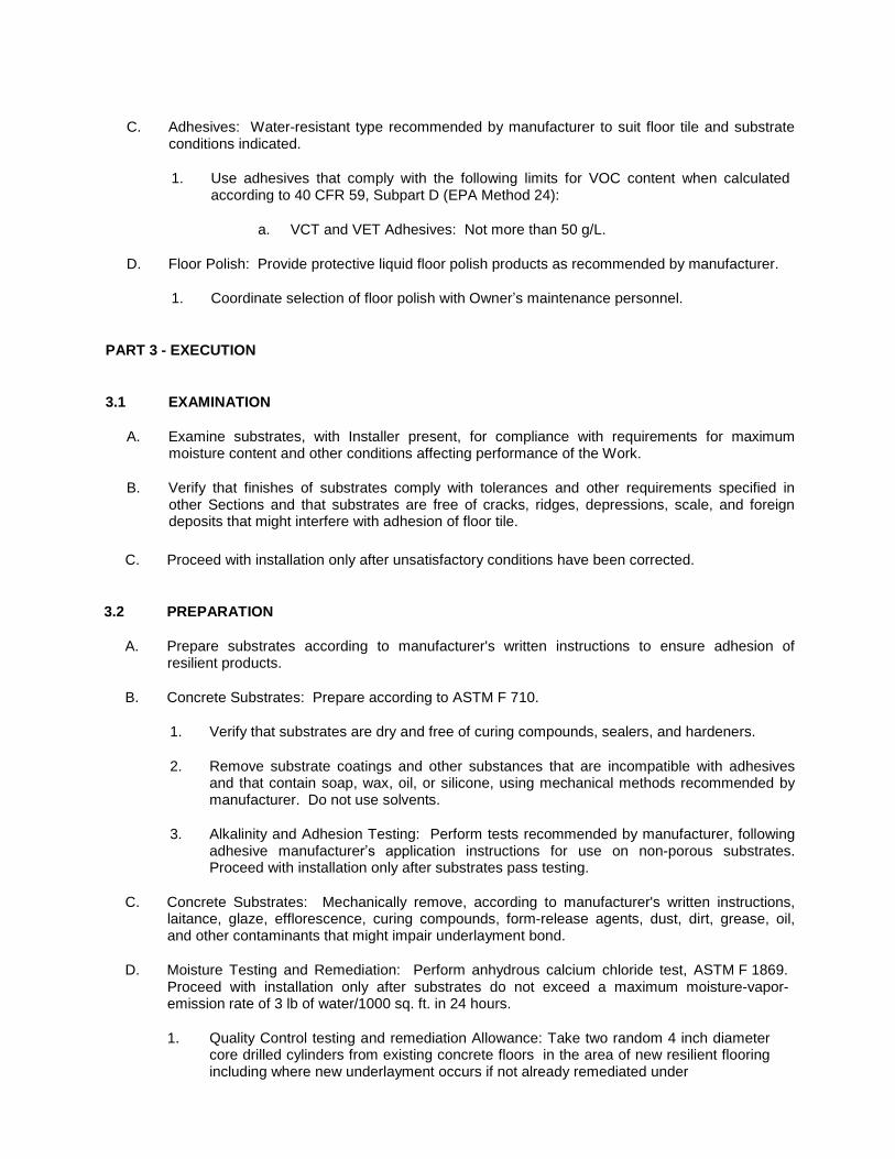
C. Adhesives: Water-resistant type recommended by manufacturer to suit floor tile and substrate
conditions indicated.
1. Use adhesives that comply with the following limits for VOC content when calculated
according to 40 CFR 59, Subpart D (EPA Method 24):
a. VCT and VET Adhesives: Not more than 50 g/L.
D. Floor Polish: Provide protective liquid floor polish products as recommended by manufacturer.
1. Coordinate selection of floor polish with Owner’s maintenance personnel.
PART 3 - EXECUTION
3.1 EXAMINATION
A. Examine substrates, with Installer present, for compliance with requirements for maximum
moisture content and other conditions affecting performance of the Work.
B. Verify that finishes of substrates comply with tolerances and other requirements specified in
other Sections and that substrates are free of cracks, ridges, depressions, scale, and foreign deposits that might interfere with adhesion of floor tile.
C. Proceed with installation only after unsatisfactory conditions have been corrected.
3.2 PREPARATION
A. Prepare substrates according to manufacturer's written instructions to ensure adhesion of
resilient products.
B. Concrete Substrates: Prepare according to ASTM F 710.
1. Verify that substrates are dry and free of curing compounds, sealers, and hardeners.
2. Remove substrate coatings and other substances that are incompatible with adhesives
and that contain soap, wax, oil, or silicone, using mechanical methods recommended by manufacturer. Do not use solvents.
3. Alkalinity and Adhesion Testing: Perform tests recommended by manufacturer, following
adhesive manufacturer’s application instructions for use on non-porous substrates. Proceed with installation only after substrates pass testing.
C. Concrete Substrates: Mechanically remove, according to manufacturer's written instructions,
laitance, glaze, efflorescence, curing compounds, form-release agents, dust, dirt, grease, oil, and other contaminants that might impair underlayment bond.
D. Moisture Testing and Remediation: Perform anhydrous calcium chloride test, ASTM F 1869.
Proceed with installation only after substrates do not exceed a maximum moisture-vapor- emission rate of 3 lb of water/1000 sq. ft. in 24 hours.
1. Quality Control testing and remediation Allowance: Take two random 4 inch diameter
core drilled cylinders from existing concrete floors in the area of new resilient flooring including where new underlayment occurs if not already remediated under

Section “Hydraulic Cement Underlayment.”
2. Core cylinders are to be sent to an independent laboratory for hydraulic conductivity
(coefficient of permeability) per ASTM D5084. The results of this test will determine the need for additional moisture vapor control coatings for the floor area in question.
3. Should the testing deliver results in excess of the moisture vapor transmission rate allowable to the flooring manufacturer, the specified moisture vapor control coating shall be applied to the substrate until acceptable moisture vapor performance is achieved.
a. The moisture mitigation prevention coating shall include all labor and material for
slab profiling, material, and application.
E. Adhesion Tests: After substrate preparation, test substrate for adhesion with underlayment
according to manufacturer's written instructions.
F. Remove substrate coatings and other substances that are incompatible with adhesives and that
contain soap, wax, oil, or silicone, using mechanical methods recommended by manufacturer. Do not use solvents.
G. Fill cracks, holes, and depressions in substrates with trowelable leveling and patching compound and remove bumps and ridges to produce a uniform and smooth substrate.
H. Do not install floor tiles until they are same temperature as space where they are to be installed.
1. Move resilient products and installation materials into spaces where they will be installed
at least 48 hours in advance of installation.
I. Sweep and vacuum clean substrates to be covered by resilient products immediately before
installation. After cleaning, examine substrates for moisture, alkaline salts, carbonation, and dust. Proceed with installation only after unsatisfactory conditions have been corrected.
3.3 FLOOR TILE INSTALLATION
A. Comply with manufacturer's written instructions for installing floor tile.
B. Lay out floor tiles from center marks established with principal walls, discounting minor offsets,
so tiles at opposite edges of room are of equal width. Adjust as necessary to avoid using cut widths that equal less than one-half tile at perimeter.
1. Lay tiles in pattern shown on drawings or square with room axis if no pattern is shown, to
comply with approved mockups.
C. Match floor tiles for color and pattern by selecting tiles from cartons in the same sequence as
manufactured and packaged, if so numbered. Discard broken, cracked, chipped, or deformed tiles.
1. Lay tiles with grain running in one direction, to comply with approved mockups, unless
otherwise indicated.
D. Scribe, cut, and fit floor tiles to butt neatly and tightly to vertical surfaces and permanent fixtures
including built-in furniture, cabinets, pipes, outlets, and door frames.
E. Extend floor tiles into toe spaces, door reveals, closets, and similar openings. Extend floor tiles
to center of door openings.

F. Maintain reference markers, holes, and openings that are in place or marked for future cutting
by repeating on floor tiles as marked on substrates. Use chalk or other nonpermanent, nonstaining marking device.
G. Install floor tiles on covers for telephone and electrical ducts, and similar items in finished floor
areas. Maintain overall continuity of color and pattern between pieces of tile installed on covers and adjoining tiles. Tightly adhere tile edges to substrates that abut covers and to cover perimeters.
1. Install floor coverings on floor cleanout covers.
H. Adhere floor tiles to flooring substrates using a full spread of adhesive applied to substrate to
produce a completed installation without open cracks, voids, raising and puckering at joints, telegraphing of adhesive spreader marks, and other surface imperfections.
3.4 CLEANING AND PROTECTION
A. Comply with manufacturer's written instructions for cleaning and protection of floor tile.
B. Perform the following operations immediately after completing floor tile installation:
1. Remove adhesive and other blemishes from exposed surfaces.
2. Sweep and vacuum surfaces thoroughly.
3. Damp-mop surfaces to remove marks and soil. Do not wash surfaces until after time
period recommended by manufacturer.
C. Floor Polish: Remove soil, visible adhesive, and surface blemishes from floor tile surfaces
before applying liquid floor polish.
1. Apply minimum two coat(s), or as otherwise recommended by the resilient floor tile
manufacturer.
D. Protect resilient products from mars, marks, indentations, and other damage from construction
operations and placement of equipment and fixtures during remainder of construction period. Use protection methods recommended in writing by manufacturer.
1. Cover products installed on horizontal surfaces with undyed, untreated building paper
until Substantial Completion.
2. Do not move heavy and sharp objects directly over surfaces. Place hardboard or
plywood panels over flooring and under objects while they are being moved. Slide or roll objects over panels without moving panels.
END OF SECTION

– PAINTING AND COATINGS PART 1 -
GENERAL
1.1 RELATED DOCUMENTS
A. Drawings and general provisions of Contract, including General and Supplementary Conditions
and Specification sections, apply to this section.
1.2 SUMMARY
A. This Section includes applying paint coating systems to items and surfaces scheduled including
surface preparation, prime coats and finish coats.
1. Section includes anti-graffiti coatings for tile.
B. Types of painting and coating systems required for the Project include the following as specified
in this section where indicated in the Room Finish and Material Schedules.
C. Related Sections: The following sections contain requirements that relate to this section:
1. Section "Hollow Metal Frames" for shop priming steel doors and frames. 2. Section “Tiling” for products to receive anti-graffiti coatings.
1.3 PAINT - (PNT)
PNT-L Acrylic latex paint for gypsum drywall soffits and ceilings. PNT-E One or two coat water-based epoxy paint for concrete block and/or gypsum
board walls/partitions. PNT-WDG Epoxy or Acrylic ester dry fall or wet fall coating for properly prepared concrete
ceiling structure and deck. PNT-UV Urethane varnish finish for wood doors and other exposed hardwood surfaces.
SC-PP Polyester polyurethane special coating for hollow metal doors and frames, and
other miscellaneous exposed steel within 8’-0” of the finished floor.
1.4 COATINGS
AG-S Anti-Graffiti Coatings. Two component, Urethane Silicone coating; with typical
coverage over all porcelain and ceramic non-glazed tile surfaces, and grout.
1.5 PAINTS AND COATINGS - GENERAL
A. Paint exposed surfaces whether or not colors are designated in "schedules," except where a
surface or material is specifically indicated not to be painted or is to remain natural. Where an item or surface is not specifically mentioned, paint the same as similar adjacent materials or

surfaces. If color or finish is not designated, the Owner will select from standard colors or finishes available.
B. Painting includes field painting areas scheduled to have walls and/or ceilings painted of all
exposed bare and covered pipes and ducts, hangers, exposed steel and iron work, and primed metal surfaces of mechanical and electrical equipment.
C. Painting is not required on prefinished items, finished metal surfaces, concealed surfaces,
operating parts, and labels.
D. Prefinished items not to be painted include the following factory-finished components:
1. Metal toilet enclosures. 2. Acoustic materials. 3. Ownerural casework. 4. Elevator equipment. 5. Finished mechanical and electrical equipment. 6. Light fixtures and device coverplates.
E. Prefinished items to be painted under this section include the following:
1. Grilles or diffusers which occur in surfaces scheduled to be painted shall be painted to
match adjacent surfaces.
F. Concealed surfaces not to be painted include wall or ceiling surfaces in the following generally
inaccessible areas:
1. Foundation spaces. 2. Furred areas. 3. Utility tunnels. 4. Pipe spaces. 5. Duct shafts. 6. Elevator shafts.
G. Non-ferrous metal surfaces not to be painted include:
1. Anodized aluminum. 2. Stainless steel. 3. Chromium plate. 4. Copper. 5. Bronze. 6. Brass.
H. Operating parts not to be painted include moving parts of operating equipment such as the
following:
1. Valve and damper operators. 2. Linkages. 3. Sensing devices. 4. Motor and fan shafts.
I. Labels: Do not paint over Underwriter's Laboratories, Factory Mutual or other code-required
labels or equipment name, identification, performance rating, or nomenclature plates.

1.6 DEFINITIONS
A. "Paint" includes coating systems materials, primers, emulsions, enamels, stains, sealers and
fillers, and other applied materials whether used as prime, intermediate, or finish coats.
1.7 SUBMITTALS
A. Product Data: Manufacturer's technical information, label analysis, and application instructions
for each material proposed for use.
1. List each material and cross-reference the specific coating and finish system and
application. Identify each material by the manufacturer's catalog number and general classification.
B. Samples for Verification Purposes: Provide samples of each color and material to be applied,
with texture to simulate actual conditions, on representative samples of the actual substrate. Define each separate coat, including block fillers and primers. Use representative colors when preparing samples for review. Resubmit until required sheen, color, and texture are achieved.
1. Provide a list of material and application for each coat of each sample. Label each
sample as to location and application.
C. Submit samples on the following substrates for the Owner's review of color and texture only:
1. Concrete: Provide two 4-inch-square samples for each color and finish. 2. Concrete Masonry: Provide two 4- by-8-inch samples of masonry, with mortar joint in the
center, for each finish and color. 3. Stained or Natural Wood: Provide two 4- by 8-inch samples of natural and stained wood
finish on actual wood surfaces. 4. Spray Applied Fireproofing: Provide a field sample 2’ x 2’ square for Owners approval.
1.8 QUALITY ASSURANCE
A. Single-Source Responsibility: Provide primers and undercoat paint produced by the same
manufacturer as the finish coats.
B. Coordination of Work: Review other sections in which primers are provided to ensure
compatibility of the total systems for various substrates. On request, furnish information on characteristics of finish materials to ensure use of compatible primers.
1. Notify the Owner of problems anticipated using the materials specified.
1.9 DELIVERY, STORAGE, AND HANDLING
A. Deliver materials to the job site in the manufacturer's original, unopened packages and
containers bearing manufacturer's name and label and the following information:
1. Product name or title of material. 2. Product description (generic classification or binder type). 3. Manufacturer's stock number and date of manufacture. 4. Contents by volume, for pigment and vehicle constituents. 5. Thinning instructions.

6. Application instructions. 7. Color name and number.
B. Store materials not in use in tightly covered containers in a well- ventilated area at a minimum
ambient temperature of 45 deg F (7 deg C). Maintain containers used in storage in a clean condition, free of foreign materials and residue.
C. Protect from freezing. Keep storage area neat and orderly. Remove oily rags and waste daily.
Take necessary measures to ensure that workers and work areas are protected from fire and health hazards resulting from handling, mixing, and application.
1.10 JOB CONDITIONS
A. Apply water-based paints only when the temperature of surfaces to be painted and surrounding
air temperatures are between 50 deg F(10 deg C) and 90 deg F (32 deg C).
B. Apply solvent-thinned paints only when the temperature of surfaces to be painted and
surrounding air temperatures are between 45 deg F (7 deg C) and 95 deg F (35 deg C).
C. Do not apply paint in snow, rain, fog, or mist, when the relative humidity exceeds 85 percent, at
temperatures less than 5 deg F (3 deg C) above the dew point, or to damp or wet surfaces.
1. Painting may continue during inclement weather if surfaces and areas to be painted are
enclosed and heated within temperature limits specified by the manufacturer during application and drying periods.
PART 2 - PRODUCTS
2.1 PAINT - (PNT)
A. General: Provide systems indicated by application and where scheduled. Primers and finish
coats are considered one system. Primers by other manufacturers shall be tested with finish system by the paint manufacturer for adhesion and the system adjusted with the approval of the Owner.
B. Barrier coats to be used to provide adequate adhesion are in addition to system primers and
finish coats and used where directed by the paint manufacturer to meet requirements.
2.2 PNT-L ACRYLIC LATEX ENAMEL, FLAT for "GB" (Gypsum board soffits, and ceilings.
Non-storage or janitor room use.
A. Prime Coat
1. Glidden Pro: 1030-1200 PVA Latex Wall Primer Sealer 2. Moore: Latex Quick Dry Primer Sealer 3. Pittsburgh: Speedhide Quick Drying Latex Primer Sealer, 6-2 4. Sherwin Williams: Pro Mar 200 Latex Wall Primer, B28W, 200 5. Tnemec 51-792 PVA Sealer
B. Two Finish Coats at 3 to 4 mils total DFT

1. Glidden Pro: 1210-XXXX Ultra-Hide 150 Latex Flat Wall Paint 2. Moore: Moore's Regal Wall Satin 3. Pittsburgh: 6-70 Speedhide Latex Flat Wall Paint 4. Sherwin-Williams: Pro Mar 200 Flat Latex B30 Series 5. Tnemec Series 6 Tneme-Cryl
2.3 PNT-L ACRYLIC LATEX ENAMEL - Semi-Gloss, for "GB" (Gypsum Board) all ceilings
and soffits.
A. System Option: Sealer/primer plus two finish coats as specified below:
1. Glidden Pro: 1030-1200 PVA Latex Primer Sealer 2. Moore: Latex Quick Dry Primer Sealer 3. Pittsburgh: Speed Hide Quick Drying latex Primer Sealer 6-2 4. Sherwin Williams: Pro Mar 200 Latex Wall Primer 5. Tnemec Series 51-792 PVA Sealer
B. Two Finish Coats System at 3 to 4 mils total DFT.
1. Glidden Pro: 1416-XXXX Ultra Hide 150 Semi Gloss Latex Enamel 2. Moore: Moorecraft Super-Hide Semi Gloss Latex Enamel 3. Pittsburgh: Speedhide Interior Latex Semi-Gloss 6-500 4. Sherwin-Williams: Pro Mar 200 Latex Enamel 5. Tnemec Series 29 Tuf-Cryl
2.4 PNT-E WATER BASE EPOXY - Semi-Gloss, for standard (non-glazed) CMU (Concrete
Block).
A. System Option: Filler plus one finish coat or filler plus two finish coats as specified below:
B. Provide block filler at rate to provide PINHOLE-FREE SURFACES.
1. Glidden Pro: 4000-1000 Bloxfil Heavy Acrylic Block Filler 2. Pittsburgh: Pitt-Glaze Block Filler 16-90 3. Sherwin-William: Heavy Duty Block Filler B42 4. Tnemec: Series 130 Enviro-Fill
C. One Finish Coat System:
1. Glidden Pro: 4426-XXXX Tru Glaze WB Semi Gloss Epoxy at 5 mils DFT min 2. Pittsburgh Paints: AquaPon WB Semi-Gloss, 98-1 Series 3. Tnemec: Series 113 at 5 mils DFT minimum (spray applied).
D. Two Finish Coats System at 5 to 6 mils DFT.
1. Glidden Pro: 4426-XXXX Tru-Glaze WB Epoxy Semi Gloss at 5 mils DFT min 2. Pittsburgh: AquaPon WB Semi-Gloss, 98 Series 3. Sherwin-Williams: Water Based Catalyzed Epoxy B70/B60V25

2.5 PNT-E WATER BASE EPOXY - Semi-Gloss, where scheduled for "GB" Gypsum Board walls, typical.
A. System Option: Sealer/primer plus two finish coats as specified below:
1. Glidden Pro: 1030-1200 PVA Latex Primer Sealer 2. Pittsburgh: Speed Hide 6-2 Sealer Primer 3. Sherwin Williams: Pro Mar Latex Wall Primer 4. Tnemec: Series 51-792 PVA Sealer
B. Two Finish Coats System at 5 to 6 mils total DFT.
1. Glidden Pro: 4426-XXXX Tru-Glaze WB Epoxy Semi Gloss at 5 mils DFT min. 2. Pittsburgh: AquaPon WB Semi-Gloss, 98 Series 3. Sherwin-Williams: Water Based Catalyzed Epoxy B70/B60V25 4. Tnemec: Series 113 at 5 mils DFT minimum (spray applied).
2.6 PNT-WDF WET FALL OR DRY FALL PAINT
A. Where scheduled for over properly prepared and exposed existing concrete ceiling structure
use one the following wet or dry fall paints:
B. Wet Fall: Finish deck, joists, beams, hangers and conduit, ONE coat Tnemec Series 15 Uni-
Bond Wet Fall at rate required for full coverage and uniform sheen.
C. Dry Fall: Finish deck, joists, beams, hangers and conduit with TWO coats 3 to 4 mils DFT at
rate required for full coverage and uniform sheen.
1. Glidden Pro: 4380-XXXX Uni Grip Modified Epoxy Dry Fall Flat 2. Pittsburgh: SuperTech 6-157 Epoxy Ester Dry Fog 3. Sherwin Williams Waterborne Acrylic Dry-Fall B42W0001 (Flat) 4. Tnemec: Series 115 (one coat possible)
2.7 PNT-UV NATURAL FINISH WOOD - SATIN, URETHANE Apply natural finish to all
exposed hardwood surfaces.
A. Stain As noted in the Finish Schedule Color Remarks
1. Glidden Pro: 1700 Woodpride Oil Stain 2. Moore: Interior Wood Finishes Penetrating Stain 3. Pittsburgh: Rez Semi-Transparent Alkyd-Oil Interior Stain 4. Sherwin Williams: S-W Oil Stain Series A49-200
B. Sealer
1. Glidden Pro: 1908-0000 Woodpride Polyurethane - Gloss 2. Moore: Benwood Satin Finish Varnish, thinned 1 pint mineral spirits per
gallon. 3. Pittsburgh: Speedhide Interior Wood Sanding Sealer 6-10 4. Sherwin Williams: A66 V91 Gloss Varnish
C. First & Second Finish Coats

1. Glidden Pro: 1902-0000 Woodpride Clear Satin Varnish 2. Moore: Benwood Satin Finish Varnish 3. Pittsburgh: Rez 77-89 Polyurethane - Satin 4. Sherwin Williams: A66 F90 Hand Rubbed Satin Varnish
2.8 SC-PP SEMI-GLOSS POLYESTER POLYURETHANE for Hollow Metal doors and frames.
1. Barrier Coat:
a. Tnemec Series 27WB Typoxy at 2 to 3 mils DFT b. Carboline Rustbond Sealer at 1 to 2 mils DFT. c. Sherwin Williams; Epolon II Rust Inhibitive Primer at 2.0 to 4 mils DFT
2. Finish Coat:
a. Tnemec Series 740 Endura-Shield 3 at 5 mils DFT b. Carboline Carbothane 133 MC at 3 to 4 mils DFT. c. Sherwin Williams, Epolon II at 3.0 to 5.0 DFT
2.9 AG-S ANTI-GRAFITTI COATING - Satin for exposed, non glazed porcelain and ceramic
wall tile.
A. Basis of Design: Provide “EC-8120” by Ecological Coatings (Clifton Park, NY 518-670-4710) or
subject to compliance with requirements, comparable low VOC, two part silicone based, non- sacrificial coatings compatible with the tile products.
B. Application: Two component in raw state, mixed at the site. Spray, roll or brush application to
achieve a 1.5 mil DFT per coat in a two coat application and in accordance with manufacturer’s written instructions. Do not over-apply.
C. Cleaning Agent: Basis of Design: Provide EC-9920 grafitti cleaner as a system with the
coating. Where comparable anti-grafitti coatings are used, the coating manufacture to supply the standard cleaner formulation for their coating.
1. Quantities: Provide (1) one standard 16 oz. container of graffiti cleaner for each 500
square feet of protected tile. Deliver multiple units to each project site in clearly marked durable container of no more than 50 lbs total weight, with manufacturing date and shelf life of contents. Provide Owner’s at each project location with contact and ordering information.
PART 3 - EXECUTION
3.1 EXAMINATION
A. Examine substrates and conditions under which painting will be performed for compliance with
requirements for application of paint. Do not begin paint application until unsatisfactory conditions have been corrected.
1. Start of painting will be construed as the Applicator's acceptance of surfaces and
conditions within a particular area.
2. Substrate defects shall be properly filled and sanded and ready for painting after the first
coat of paint. Start of finish topcoats of defective surfaces, including joint treatments in

gypsum board surfaces, will indicate acceptance of the substrate and any costs associated of correcting such defect shall be borne by the painter.
3. Repairs of defective areas will require repainting of the entire surface to the nearest
change in wall plane, floor and ceiling. No touch up only painting of corrected areas of repair.
4. Examine and prepare all surfaces under adequate illumination, ventilation and
temperature requirements.
B. Any scraping, sanding, and repairing of existing substrates in excess of 25% of the total surface
area (by room) shall have the existing coating system completely removed to the underlying substrate in conformance to SSPC-SP 3 Power Tool Cleaning or SSPC-SP 6 Commercial Blast Cleaning.
3.2 PREPARATION
A. General Procedures: Remove new or existing hardware and hardware accessories, plates,
machined surfaces, lighting fixtures, and similar items in place that are not to be painted, or provide surface-applied protection prior to surface preparation and painting. Remove these items if necessary for complete painting of the items and adjacent surfaces. Following completion of painting operations in each space or area, have items reinstalled by workers skilled in the trades involved.
1. Clean surfaces before applying paint or surface treatments. Remove oil and grease prior
to cleaning. Schedule cleaning and painting so that dust and other contaminants from the cleaning process will not fall on wet, newly painted surfaces.
B. Surface Preparation: Clean and prepare surfaces to be painted in accordance with the
manufacturer's instructions for each particular substrate condition and as specified.
1. Provide barrier coats over incompatible primers or remove and reprime.
C. Cementitious Materials: Prepare concrete, and concrete masonry block, surfaces to be painted.
Remove efflorescence, chalk, dust, dirt, grease, oils, and release agents. Roughen as required to remove glaze. If hardeners or sealers have been used to improve curing, use mechanical methods of surface preparation.
1. Use abrasive blast-cleaning methods if recommended by the paint manufacturer. 2. Determine alkalinity and moisture content of surfaces by performing appropriate tests. If
surfaces are sufficiently alkaline to cause blistering and burning of finish paint, correct this condition before application.
3. Do not paint surfaces where moisture content exceeds that permitted in manufacturer's printed directions.
D. Materials Preparation: Carefully mix and prepare paint materials in accordance with
manufacturer's directions.
1. Maintain containers used in mixing and application of paint in a clean condition, free of
foreign materials and residue. 2. Stir material before application to produce a mixture of uniform density; stir as required
during application. Do not stir surface film into material. Remove film and, if necessary, strain material before using.

3.
limits.
E. Tinting: Tint each undercoat a lighter shade to facilitate identification of each coat where
multiple coats of the same material are applied. Tint undercoats to match the color of the finish coat, but provide sufficient differences in shade of undercoats to distinguish each separate coat.
3.3 APPLICATION
A. Apply paint in accordance with manufacturer's directions. Use applicators and techniques best
suited for substrate and type of material being applied.
B. Do not paint over dirt, rust, scale, grease, moisture, scuffed surfaces, finished caulking beads,
or conditions detrimental to formation of a durable paint film.
C. Paint colors, surface treatments, and finishes are indicated in the Material Legend and Finish
Schedules located on the Drawings.
1. Provide finish coats that are compatible with primers used. 2. The number of coats and film thickness required is the same regardless of the application
method. Do not apply succeeding coats until the previous coat has cured as recommended by the manufacturer. Sand between applications where sanding is required to produce an even smooth surface in accordance with the manufacturer's directions.
3. Apply additional coats when undercoats, stains, or other conditions show through final coat of paint until paint film is of uniform finish, color, and appearance. Give special attention to ensure that surfaces, including edges, corners, crevices, welds, and exposed fasteners, receive a dry film thickness equivalent to that of flat surfaces.
4. The term "exposed surfaces" includes areas visible when permanent or built-in fixtures, convector covers, covers for finned tube radiation, grilles, and similar components are in place. Extend coatings in these areas as required to maintain the system integrity and provide desired protection.
5. Paint surfaces behind movable equipment and furniture same as similar exposed surfaces. Paint surfaces behind permanently fixed equipment or furniture with prime coat only before final installation of equipment.
6. Paint interior surfaces of ducts, where visible through registers or grilles, with a flat, nonspecular black paint.
7. Paint back sides of access panels and removable or hinged covers to match exposed surfaces.
8. Sand lightly between each succeeding enamel or varnish coat. 9. Omit primer on metal surfaces that have been shop-primed and touch up painted.
D. Scheduling Painting: Apply first coat to surfaces that have been cleaned, pretreated, or
otherwise prepared for painting as soon as practicable after preparation and before subsequent surface deterioration.
1. Allow sufficient time between successive coats to permit proper drying. Do not recoat
until paint has dried to where it feels firm, and does not deform or feel sticky under moderate thumb pressure and where application of another coat of paint does not cause lifting or loss of adhesion of the undercoat.
E. Minimum Coating Thickness: Apply materials at not less than the manufacturer's
recommended spreading rate. Provide a total dry film thickness of the entire system as recommended by the manufacturer.

F. Block Fillers: Provide block fillers to concrete masonry block at a rate to ensure complete coverage to provide PINHOLE FREE surfaces.
1. PINHOLE FREE means there will be no visible perforations or pore-like holes in paint film
either to the naked eye or under low magnification. Paint film shall be uniform and continuous with no breaks in it which could allow moisture to reach substrate.
G. Prime Coats: Before application of finish coats, apply a prime coat of material as recommended
by the manufacturer to material that is required to be painted or finished and has not been prime coated by others. Recoat primed and sealed surfaces where evidence of suction spots or unsealed areas in first coat appears, to assure a finish coat with no burn through or other defects due to insufficient sealing.
H. Pigmented (Opaque) Finishes: Completely cover to provide an opaque, smooth surface of
uniform finish, color, appearance, and coverage. Cloudiness, spotting, holidays, laps, brush marks, runs, sags, ropiness, or other surface imperfections will not be acceptable.
I. Transparent (Clear) Finishes: Use multiple coats to produce a glass-smooth surface film of
even luster. Provide a finish free of laps, cloudiness, color irregularity, runs, brush marks, orange peel, nail holes, or other surface imperfections.
1. Provide satin finish for final coats.
J. Completed Work: Match approved samples for color, texture, and coverage. Remove, refinish,
or repaint work not in compliance with specified requirements.
3.4 CLEANING
A. Cleanup: At the end of each work day, remove empty cans, rags, rubbish, and other discarded
paint materials from the site.
B. Upon completion of painting, clean glass and paint-spattered surfaces. Remove spattered paint
by washing and scraping, using care not to scratch or damage adjacent finished surfaces.
3.5 PROTECTION
A. Protect work of other trades, whether to be painted or not, against damage by painting. Correct
damage by cleaning, repairing or replacing, and repainting, as acceptable to Owner.
B. Provide "wet paint" signs to protect newly painted finishes. Remove temporary protective
wrappings provided by others for protection of their work after completion of painting operations.
1. At completion of construction activities of other trades, touch up and restore damaged or
defaced painted surfaces.
END OF SECTION

- HYDRAULIC ELEVATORS PART 1 -
GENERAL
1.1 SUMMARY
A. This Section includes requirements for holeless hydraulic passenger elevators.
B. Information provided for passenger elevators is diagrammatic. Contractor is responsible for
delegated design for the elevator, power and controls, hoistway and supporting components including, but not necessarily limited to the following:
1. Final Hoistway and final cab size. 2. Pits, Ladder, Sumps and Lighting as required by AHJ’s. 3. Machine room size, services and equipment. 4. Power requirements, including new service and phase to the elevator equipment. 5. Metal Fabrications for:
a. Attachment plates and angle brackets for supporting guide-rail brackets. b. Structural-steel shapes for subsills. c. Pit ladders. d. Hoist beams.
6. Complete cab interior finishes 7. Hoistway doors and door frame finishes. 8. Fire protection sensors, alarms and communications
C. Provide a complete and functioning elevator system, compliant with Authorities Having
Jurisdication:
D. Related Sections:
1. Section “Limited Use, Limited Application Elevators” 2. Section “Wheelchair Lifts”
1.2 DEFINITIONS
A. Defective Elevator Work: Repeated operation or control system failures; performances below
specified ratings; excessive wear; unusual deterioration or aging of materials or finishes; unsafe conditions; the need for excessive maintenance; abnormal noise or vibration; and similar unusual, unexpected, and unsatisfactory conditions.
1.3 SUBMITTALS
A. Product Data: Include capacities, sizes, performances, operations, safety features, finishes,
and similar information.
B. Shop Drawings: Show plans, elevations, sections, and large-scale details indicating service at
each landing, machine room layout, coordination with building structure, relationships with other construction, and locations of equipment and signals. Indicate variations from specified

requirements, maximum dynamic and static loads imposed on building structure at points of support, and maximum and average power demands.
C. Samples: For exposed finishes of cars, hoistway doors and frames, and signal equipment; 3-
inch- square samples of sheet materials; and 4-inch lengths of running trim members. When requested, submit color charts of exposed finishes for color selection.
D. Manufacturer Certificates: Signed by elevator manufacturer certifying that hoistway, pit, and
machine room layout and dimensions, as shown on Drawings, and electrical service, as shown and specified, are adequate for elevator system being provided.
E. Maintenance Manuals: Include operation and maintenance instructions, parts listing with
sources indicated, recommended parts inventory listing, emergency instructions, and similar information. Submit for Owner's information at Project closeout.
F. Inspection and Acceptance Certificates and Operating Permits: As required by authorities
having jurisdiction for normal, unrestricted elevator use.
G. Qualification Data: For manufacturer.
1.4 QUALITY ASSURANCE
A. Manufacturer Qualifications:
1. Regularly engages in manufacturing, installing and servicing elevators of the type
specified. 2. Manufactures major elevator components in North America.
B. Installer Qualifications: Elevator manufacturer or an experienced installer approved by elevator
manufacturer who has completed elevator installations similar in material, design, and extent to that indicated for this Project and with a record of successful in-service performance.
C. Regulatory Requirements: In addition to local governing regulations, comply with applicable
provisions in ASME A17.1, "Safety Code for Elevators and Escalators."
D. Accessibility Requirements: In addition to local governing regulations, comply with Section 4.10
in the U.S. Ownerural & Transportation Barriers Compliance Board's "Americans with Disabilities Act (ADA), Accessibility Guidelines (ADAAG)."
1.5 DELIVERY, STORAGE, AND HANDLING
A. Store materials, components and equipment in manufacturer’s original protective packaging in a
dry protected area.
B. Handle materials in accordance with manufacturer’s recommendations to prevent damage,
soiling, or deterioration.

1.6 COORDINATION
A. Coordinate installation of sleeves, block outs, and items that are embedded in concrete or
masonry for elevator equipment. Furnish templates and installation instructions and deliver to Project site in time for installation.
B. Coordinate locations and dimensions of other work relating to hydraulic elevators including pit
ladders, sumps, and floor drains in pits; entrance subsills; and electrical service, electrical outlets, lights, and switches in pits and machine rooms.
1.7 WARRANTY
A. Special Manufacturer's Warranty: Written warranty, signed by manufacturer agreeing to repair,
restore, or replace defective elevator work within specified warranty period.
1. Warranty Period: 12 months from date of Substantial Completion.
1.8 MAINTENANCE SERVICE
A. Initial Maintenance Service: Beginning at Substantial Completion, provide 12 months' full
maintenance service by skilled employees of the elevator Installer. Include monthly preventive maintenance, repair or replacement of worn or defective components, lubrication, cleaning, and adjusting as required for proper elevator operation at rated speed and capacity. Provide parts and supplies as used in the manufacture and installation of original equipment.
1. Perform maintenance, including emergency callback service, during normal working
hours. 2. Include 24-hour-per-day, 7-day-per-week emergency callback service.
a. Response Time: Two hours or less.
PART 2 - PRODUCTS
2.1 MANUFACTURERS
A. Basis-of-Design Product: The design for hydraulic elevators is based on ThyssenKrupp
Elevator model AAME 21 (holeless) with EP type power unit.
B. Subject to compliance with requirements, provide the named product or a comparable product
by one of the following:
1. KONE Inc. 2. Otis Elevator Co. 3. Schindler Elevator Corp.

2.2 MATERIALS AND COMPONENTS
A. General: Provide manufacturer's standard elevator systems. Where components are not
otherwise indicated, provide standard components, published by manufacturer as included in standard pre-engineered elevator systems and as required for a complete system.
a. Provide an affidavit of Non-Proprietary Equipment representing compliance with
established standards for Universal Serviceability and Maintainability. Include the following provisions:
1) Spare parts with regard to universal availability to elevator contractor
designated by the Owner to maintain and service the equipment. No exchange-only provisions.
2) Diagnostics controls with all available diagnostic function available on board or in a separate device, providing restricted access to all parameters necessary to adjust and maintain operation by any elevator contractor.
3) Training. After warranty period, OEM training shall be made available to anyone who desires to learn maintenance and adjustment of the system. Provide training at reasonable cost, appropriate to the level desired.
4) Unrestricted Technical Support to Owner’s designated elevator contractor(s).
5) Unrestricted Engineering support to Owner’s designated elevator contractor(s).
6) Availability of complete Replacement Documentation at Owner request; at reasonable cost.
B. Pump Units: Positive-displacement type with a maximum of 10 percent variation between no
load and full load and with minimum pulsations. Provide the following:
1. Passenger Elevator: provide elevator motor with solid-state starting.
C. Hydraulic Silencers: Provide hydraulic silencer containing pulsation-absorbing material in a
blowout-proof housing at pump unit.
D. Piping: Provide size, type, and weight piping recommended by manufacturer, and provide
flexible connectors to minimize sound and vibration transmissions from power unit.
E. Hydraulic Oil: Provide hydraulic oil of proper grade in the quantity recommended by
manufacturer.
1. Provide dielectric couplings between power unit and cylinder units. 2. Casing for Underground Piping: PVC pipe complying with ASTM D 1785 joined with PVC
fittings complying with ASTM D 2466 and solvent cement complying with ASTM D 2564.
F. Inserts: Furnish required concrete and masonry inserts and similar anchorage devices for
installing guide rails, machinery, and other components of elevator work where installation of devices is specified in another Specification Section.
G. Protective Cylinder Casings: HDPE pipe casings complying with ASME A17.1, of sufficient size
to provide not less than 1-inch clearance from cylinder, and extending above pit floor.
H. Car Frame and Platform: Formed or structural steel members, bolted or welded together.

I. Finish Materials: Provide the following materials and finishes for exposed parts of elevator car enclosures, car doors, hoistway entrance doors and frames, and signal equipment as indicated:
1. Enameled-Steel Sheet: Cold-rolled steel sheet complying with ASTM A 366/A 366M,
matte finish, stretcher-leveled standard of flatness; hot-rolled steel sheet complying with ASTM A 569/A 569M may be used for door frames. Provide with factory-applied enamel finish; colors as selected by Owner.
2. Prime-Painted Steel Sheet: Cold-rolled steel sheet, ASTM A 366/A 366M, or hot-rolled steel sheet, ASTM A 569/A 569M, with factory-applied rust-inhibitive primer.
3. Plastic Laminate: High-pressure type complying with NEMA LD 3, Type HGP for postformed applications and Type HGS for flat applications; color, texture, and pattern as selected by Owner from plastic-laminate manufacturer's full range of products.
4. Rolled Steel Floor Plate: ASTM A 786/A 786M.
J. Stainless-Steel Sheet: ASTM A 240/A 240M, Type 304.
1. Exposed finish: No. 4 non-directional finish, satin polished and clear coated after rolling.
K. Stainless-Steel Bars: ASTM A 276, Type 304.
L. Stainless-Steel Tubing: ASTM A 554, Grade MT 304.
2.3 OPERATION SYSTEMS
A. Passenger Elevators: Provide manufacturer's standard microprocessor operation system for
each elevator or group of elevators as required to provide type of operation system indicated.
1. Single Elevator: Provide "selective collective automatic operation" as defined in
ASME A17.1.
B. Auxiliary Operations: In addition to primary operation system features, provide the following
operational features for elevators where indicated.
1. Standby Power Operation: On activation of standby power, cars are returned to a field
programmable floor, doors cycled, and parked with doors closed. The door open button is to remain active to allow passengers to exit the car. Car is selected for service on standby power by a switch located at main floor elevator lobby.
2. Loaded-Car Bypass: When car load exceeds a predetermined weight, car will respond only to car calls, not to hall calls. Predetermined weight can be adjusted.
C. Security Features: In addition to above operational features, provide the following security
features, where indicated. Security features shall not affect emergency firefighters' service. The main landing will not be locked out from the car to allow access out of the building to the "security level".
1. Keyswitch Feature: Car and hall push buttons are activated and deactivated by security
keyswitches. Key is removable only in deactivated position.

2.4 SIGNAL EQUIPMENT
A. General: Provide signal equipment for each elevator or group of elevators with hall-call and car-
call buttons that light when activated and remain lit until call has been fulfilled. Fabricate lighted elements of acrylic or other permanent, nonyellowing translucent plastic.
B. Car Control Stations: Provide fully recessed car control stations with applied metal faceplates.
Mount in return panel adjacent to car door, if not otherwise indicated.
C. Emergency Communication System: Provide system that complies with ASME A17.1 and the
U.S. Ownerural & Transportation Barriers Compliance Board's "Americans with Disabilities Act (ADA), Accessibility Guidelines (ADAAG)." On activation, system dials preprogrammed number of monitoring station and identifies elevator location to monitoring station. System provides two-way voice communication without using a handset and provides visible signals that indicate when system has been activated and when monitoring station has responded. System is contained in flush-mounted cabinet, with identification, instructions for use, and battery backup power supply.
D. Fire Department Communication System: Provide flush-mounted cabinet in each car and
required conductors in traveling cable for fire department communication system specified by code.
E. Car Position Indicator: For elevator cars, provide digital-display type (passenger elevator),
located above car door or above car control station. Also provide audible signal to indicate to passengers that car is either stopping at or passing each of the floors served.
1. Include travel direction arrows if not provided in car control station.
F. Passenger Elevator Hall Push-Button Stations: Provide hall push-button stations at each
landing as indicated.
1. Provide units with flat faceplate for mounting with body of unit recessed in wall.
G. Hall Lanterns: Provide units with illuminated arrows, but provide single arrow at terminal
landings.
1. Provide units with flat faceplate for mounting with body of unit recessed in wall and with
illuminated elements projecting from faceplate for ease of angular viewing. 2. Place lanterns either above each hoistway entrance, unless otherwise indicated. Mount
at a minimum of 72 inches above finished floor. 3. With each lantern, provide audible signals indicating car arrival and direction of travel.
Signals sound once for up and twice for down.
H. Hall Position Indicators: Provide illuminated-signal type or digital-display type, located above
each hoistway entrance at ground floor. Provide units with flat faceplate for mounting with body of unit recessed in wall.
1. Integrate ground-floor hall lanterns with hall position indicators.

2.5 DOOR REOPENING DEVICES
A. Infrared Array: Provide door reopening devices with a uniform array of 40 or more
microprocessor-controlled, infrared light beams projecting across car entrance. Interruption of one or more of the light beams shall cause doors to stop and reopen.
1. Nudging Feature: After car doors are prevented from closing for a predetermined
adjustable time, through activating door reopening device, a loud buzzer shall sound. When the doors are released, the doors shall begin to close at reduced kinetic energy.
2.6 PASSENGER ELEVATOR CAR ENCLOSURES
A. General: Provide manufacturer's painted enamel steel metal car enclosures, with removable
wood wall panels with specified finish, suspended ceiling, trim, accessories, access doors, doors, power door operators, sills (thresholds), lighting, and ventilation.
1. Plastic-Laminate Wall Panels: Plastic laminate adhesively applied to 1/2-inch fire-
retardant-treated particleboard with manufacturer's standard protective edge trim. Panels have a flame-spread rating of 25 or less, when tested according to ASTM E 84.
a. Color and pattern selected by Owner from manufacturer’s standard laminates.
b. Horizontal application.
2. Fabricate car with recesses and cutouts for signal equipment. 3. Fabricate car door frame integrally with front wall of car. 4. Passenger Elevator cab base material: Flush, hollow-metal, baked enamel steel. 5. Sills:
a. Extruded metal, with groove(s) in top surface, 1/4 inch thick. Provide mill finish aluminum.
6. Translucent Ceiling: Backed enamel suspended frame with white transluscent diffusers.
Concealed lighting above panels.
7. Flooring: Vinyl Composition Tile. Basis of Design: Armstrong Excelon or approved
equal. a. Color and Pattern to match existing adjacent hallway. If no hallway tile, then as
selected by Owner from manufacturers full range.
8. Handrails: Manufacturer's handrails, satin stainless steel to match ceiling panels.
2.7 PASSENGER HOISTWAY ENTRANCES
A. General: Provide manufacturer's standard horizontal-sliding, door-and-frame hoistway
entrances complete with track systems, hardware, sills, and accessories. Provide frame size and profile to coordinate with hoistway wall construction.
1. Where gypsum board wall construction is indicated, provide self-supporting frames with
reinforced head sections.
B. Materials and Fabrication: Provide manufacturer's standards but not less than the following:
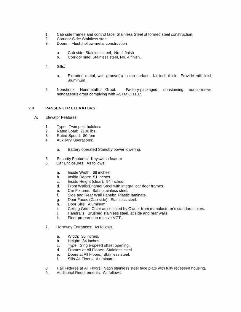
1. Cab side frames and control face: Stainless Steel of formed steel construction. 2. Corridor Side: Stainless steel. 3. Doors : Flush,hollow-metal construction
a. Cab side: Stainless steel, No. 4 finish b. Corridor side: Stainless steel, No. 4 finish.
4. Sills:
a. Extruded metal, with groove(s) in top surface, 1/4 inch thick. Provide mill finish
aluminum.
5. Nonshrink, Nonmetallic Grout: Factory-packaged, nonstaining, noncorrosive,
nongaseous grout complying with ASTM C 1107.
2.8 PASSENGER ELEVATORS
A. Elevator Features
1. Type: Twin post holeless 2. Rated Load: 2100 lbs. 3. Rated Speed: 80 fpm 4. Auxiliary Operations:
a. Battery operated Standby power lowering.
5. Security Features: Keyswitch feature 6. Car Enclosures: As follows:
a. Inside Width: 68 inches. b. Inside Depth: 51 inches. c. Inside Height (clear): 94 inches. d. Front Walls:Enamel Steel with integral car door frames. e. Car Fixtures: Satin stainless steel. f. Side and Rear Wall Panels: Plastic laminate. g. Door Faces (Cab side): Stainless steel. h. Door Sills: Aluminum i. Ceiling Grid: Color as selected by Owner from manufacturer’s standard colors. j. Handrails: Brushed stainless steel, at side and rear walls. k. Floor prepared to receive VCT.
7. Hoistway Entrances: As follows:
a. Width: 36 inches. b. Height: 84 inches. c. Type: Single-speed offset opening. d. Frames at All Floors: Stainless steel e. Doors at All Floors: Stainless steel. f. Sills All Floors: Aluminum.
8. Hall Fixtures at All Floors: Satin stainless steel face plate with fully recessed housing. 9. Additional Requirements: As follows:

a. Provide inspection certificate in each car, mounted under acrylic cover with satin stainless steel frame.
10. Additional Requirements: As follows:
a. Door reopening device.
PART 3 - EXECUTION
3.1 EXAMINATION
A. Examine elevator areas, with Installer present, for compliance with requirements for installation
tolerances and other conditions affecting performance. Verify critical dimensions, and examine supporting structure and other conditions under which elevator work is to be installed. Proceed with installation only after unsatisfactory conditions have been corrected.
1. For the record, prepare a written report, endorsed by Installer, listing dimensional
discrepancies and conditions detrimental to performance.
3.2 INSTALLATION
A. Install cylinders plumb and accurately centered for elevator car position and travel. Anchor
securely in place, supported at pit floor.
B. Welded Construction: Provide welded connections for installing elevator work where bolted
connections are not required for subsequent removal or for normal operation, adjustment, inspection, maintenance, and replacement of worn parts. Comply with AWS standards for workmanship and for qualifications of welding operators.
C. Sound Isolation: Mount rotating and vibrating equipment on vibration-isolating mounts designed
to effectively prevent transmission of vibrations to structure and thereby eliminate sources of structure-borne noise from elevator system.
D. Install piping above the floor, where possible. Where not possible, install underground piping in
Schedule 40 PVC pipe casing assembled with solvent-cement fittings.
E. Lubricate operating parts of systems as recommended by manufacturers.
F. Alignment: Coordinate installation of hoistway entrances with installation of elevator guide rails
for accurate alignment of entrances with cars. Where possible, delay installation of sills and frames until car is operable in shaft. Reduce clearances to minimum, safe, workable dimension at each landing.
G. Leveling Tolerance: 1/4 inch, up or down, regardless of load and direction of travel.
H. Set sills flush with finished floor surface at landing. Fill space under sill solidly with nonshrink,
nonmetallic grout.

3.3 FIELD QUALITY CONTROL
A. Acceptance Testing: On completion of elevator installation and before permitting use (either
temporary or permanent) of elevators, perform acceptance tests as required and recommended by ASME A17.1 and by governing regulations and agencies.
B. Advise Owner, and authorities having jurisdiction in advance of dates and times tests are to be
performed on elevators.
3.4 ADJUSTING
A. Make necessary adjustments of operating devices and equipment to ensure elevator operates
safely, accurately, and smoothly.
3.5 DEMONSTRATION
A. Instruct Owner's personnel in proper use, operations, and daily maintenance of elevators.
Review emergency provisions, including emergency access and procedures to be followed at time of operational failure and other building emergencies. Train Owner's personnel in procedures to follow in identifying sources of operational failures or malfunctions. Confer with Owner on requirements for a complete elevator maintenance program.
B. Make a final check of each elevator operation with Owner's personnel present and before date
of Substantial Completion. Determine that operation systems and devices are functioning properly.
3.6 PROTECTION
A. Temporary Use: Do not use elevators for construction purposes unless cars are provided with
temporary enclosures, either within finished cars or in place of finished cars, to protect finishes from damage.
1. Provide full maintenance service by skilled, competent employees of elevator Installer for
elevators used for construction purposes. Include preventive maintenance, repair or replacement of worn or defective components, lubrication, cleaning, and adjusting as required for proper elevator operation at rated speed and capacity. Use same parts and supplies as used in the manufacture and installation of original equipment.
2. Provide protective coverings, barriers, devices, signs, and other procedures to protect elevators. If, despite such protection, elevators become damaged, engage elevator Installer to restore damaged work so that no evidence remains of correction work. Return items that cannot be refinished in the field to the shop, make required repairs and refinish entire unit, or provide new units as required.
END OF SECTION

- WHEELCHAIR LIFTS PART 1 -
GENERAL
1.1 RELATED DOCUMENTS
A. Drawings and general provisions of the Contract, including General and Supplementary
Conditions and Specification Sections, apply to this Section.
1.2 SUMMARY
A. Section Includes:
1. Vertical platform lifts.
B. Related Requirements:
1. Section "Cast-in-Place Concrete" for setting sleeves, inserts, and anchoring devices in concrete.
1.3 DEFINITIONS
A. Definitions in ASME A18.1 apply to Work of this Section.
1.4 ACTION SUBMITTALS
A. Product Data: For each type of product.
1. Include construction details, material descriptions, dimensions of individual components,
and finishes for lifts. 2. Include rated capacities, operating characteristics, electrical characteristics, safety
features, controls, finishes, and accessories.
B. Shop Drawings: For each lift.
1. Include plans, elevations, sections, details, attachments to other work, and required
clearances. 2. Indicate dimensions, weights, loads, and points of load to building structure.
3. Include details of equipment assemblies, method of field assembly, components, and location and size of each field connection.
4. Include diagrams for power, signal, and control wiring.
C. Samples for Initial Selection: For surfaces and components with factory-applied color finishes.
1. Include Samples of integrally colored materials and accessories involving color selection.
D. Samples for Verification: For each type of exposed finish required, prepared on Samples of sizes indicated below:
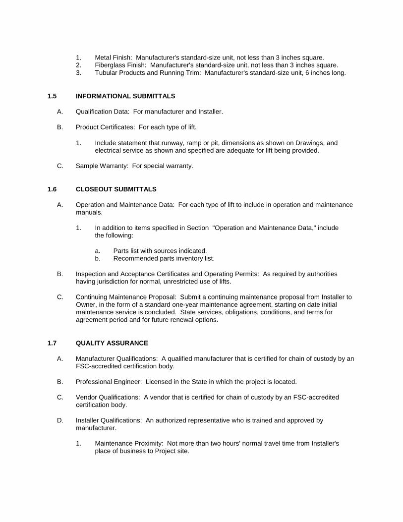
1. Metal Finish: Manufacturer's standard-size unit, not less than 3 inches square. 2. Fiberglass Finish: Manufacturer's standard-size unit, not less than 3 inches square. 3. Tubular Products and Running Trim: Manufacturer's standard-size unit, 6 inches long.
1.5 INFORMATIONAL SUBMITTALS
A. Qualification Data: For manufacturer and Installer.
B. Product Certificates: For each type of lift.
1. Include statement that runway, ramp or pit, dimensions as shown on Drawings, and electrical service as shown and specified are adequate for lift being provided.
C. Sample Warranty: For special warranty.
1.6 CLOSEOUT SUBMITTALS
A. Operation and Maintenance Data: For each type of lift to include in operation and maintenance
manuals.
1. In addition to items specified in Section "Operation and Maintenance Data," include
the following:
a. Parts list with sources indicated. b. Recommended parts inventory list.
B. Inspection and Acceptance Certificates and Operating Permits: As required by authorities
having jurisdiction for normal, unrestricted use of lifts.
C. Continuing Maintenance Proposal: Submit a continuing maintenance proposal from Installer to
Owner, in the form of a standard one-year maintenance agreement, starting on date initial maintenance service is concluded. State services, obligations, conditions, and terms for agreement period and for future renewal options.
1.7 QUALITY ASSURANCE
A. Manufacturer Qualifications: A qualified manufacturer that is certified for chain of custody by an
FSC-accredited certification body.
B. Professional Engineer: Licensed in the State in which the project is located.
C. Vendor Qualifications: A vendor that is certified for chain of custody by an FSC-accredited
certification body.
D. Installer Qualifications: An authorized representative who is trained and approved by
manufacturer.
1. Maintenance Proximity: Not more than two hours' normal travel time from Installer's
place of business to Project site.

1.8 WARRANTY
A. Special Warranty: Manufacturer agrees to repair or replace components of lifts that fail in
materials or workmanship within specified warranty period.
1. Warranty Period: Two years from date of Substantial Completion.
PART 2 - PRODUCTS
2.1 PERFORMANCE REQUIREMENTS
A. Accessibility Requirements: Comply with applicable provisions in ICC A117.1.
B. Regulatory Requirements: Comply with ASME A18.1, "Safety Standard for Platform Lifts and
Stairway Chairlifts."
2.2 VERTICAL PLATFORM LIFT
A. Vertical Platform Lift, General: Pre-engineered lift system.
1. Basis-of-Design Product: Subject to compliance with requirements, provide Multilift VPL
by Savaria Lift Type 2or comparable product by one of the following:
a. Inclinator Company of America. b. Liftavator, Inc. c. National Wheel-O-Vator Co., Inc. (The); a division of ThyssenKrupp Access. d. Symmetry Elevator
B. Number of Stops: Two.
C. Platform Size: 36 by 48 inches.
D. Door Operation and Clear Opening Width: Low-energy, power-operated doors that remain
open for 20 seconds minimum; end door with minimum 32-inch clear opening width.
E. Rated Speed: 8 fpm.
F. Power Supply: 1 HP 110 VAC.
G. Emergency Operation: Provide manual operation and battery power system to raise or lower
unit in case of malfunction or power loss.
H. Attendant Operation: Provide attendant call device at each landing.
I. Self-Supporting Unit: Support vertical loads of unit only at base, with lateral support only at
landing levels.
J. Platform Enclosure: Manufacturer's standard enclosure assembly.
1. Platform Enclosure: Rectangular steel-tube frame with flush steel-sheet panels.

2. Platform-Enclosure Doors: Rectangular steel-tube frame glazed with 6.0-mm-thick, clear acrylic glazing and with 12-inch- high, steel kick panels.
K. Platform: Steel sheet or galvanized-steel sheet with matte or primed finish suitable to accept
flooring.
L. Ramp: Retractable ramp matching platform to provide transition from lower floor to lift platform.
Ramp lowers to floor automatically when lifts reach lower landing and door opens. Ramp rises automatically when lift control is activated for lift to leave lower landing.
1. Ramp Size: End ramps a minimum of 32 inches wide; length as required for slope. 2. Ramp Slope: Maximum 1:12. 3. Ramp Finish: Finish ramps to match metal finish on lift platform. Provide non-skid
surface.
2.3 MATERIALS
A. Steel Plates, Shapes, and Bars: ASTM A 36.
B. Steel Tubing: ASTM A 500.
C. Steel Pipe: ASTM A 53; standard weight (Schedule 40) unless otherwise indicated or required by loads.
D. Steel Sheet: ASTM A 1008, cold-rolled commercial steel (CS) or ASTM A 1011 hot-rolled,
commercial steel (CS); as required for each use.
E. Aluminum: Alloy and temper recommended by aluminum producer and finisher for type of use,
corrosion resistance, and finish indicated; manufacturer's standard strengths and thicknesses for type of use.
1. Extruded Aluminum: ASTM B 221. 2. Aluminum Sheet and Plate: ASTM B 209.
F. Stainless-Steel Bars and Shapes: ASTM A 276, Type 304.
G. Stainless-Steel Tubing: ASTM A 554, Grade MT-304.
H. Stainless-Steel Sheet, Strip, and Plate: ASTM A 240 or ASTM A 666, Type 304.
I. Fiberglass: Multiple laminations of glass-fiber-reinforced polyester resin with UV-light-stable,
colorfast, nonfading, weather- and stain-resistant, colored polyester gel coat, and manufacturer's standard finish.
J. Glass: As indicated by manufacturer's designations and complying with ASME A18.1.
1. Safety Glass Products: Glass tested according to laminated-glass requirements of
16 CFR 1201, Category II, or ANSI Z97.1, Class A. 2. Safety Glass Marking: Glass permanently marked with certification label of SGCC or
another certification agency acceptable to authorities having jurisdiction. Label shall indicate manufacturer's name, type of glass, thickness, safety glazing standard with which glass complies, and be located so as to be visible after installation.

K. Inserts: Furnish required concrete and masonry inserts and similar anchorage devices for installing structural members, guide rails, machines, and other lift components where installation of devices is specified in another Section.
L. Expansion Anchors: Anchor-bolt-and-sleeve assembly of material indicated below with
capability to sustain a load equal to 10 times the load imposed as determined by testing according to ASTM E 488 conducted by a qualified independent testing agency.
1. Material: Carbon-steel components, zinc plated to comply with ASTM B 633,
Class Fe/Zn 5. 2. Material: Group 1, Alloy 304 or Alloy 316, stainless-steel bolts and nuts complying with
ASTM F 593 and ASTM F 594.
M. Nonshrink, Nonmetallic Grout: Factory-packaged, nonstaining, noncorrosive, nongaseous grout
complying with ASTM C 1107/C 1107M.
2.4 GENERAL FINISH REQUIREMENTS
A. Protect mechanical finishes on exposed surfaces from damage by applying a strippable,
temporary protective covering before shipping.
B. Appearance of Finished Work: Noticeable variations in same piece are not acceptable.
Variations in appearance of adjoining components are acceptable if they are within the range of approved Samples and are assembled or installed to minimize contrast.
2.5 FINISHES
A. Steel Factory Finish:
1. Baked-Enamel or Powder-Coat Finish: After cleaning and pretreating, apply
manufacturer's standard two-coat, baked-on finish consisting of prime coat and thermosetting topcoat to a minimum dry film thickness of 2 mils.
2. Color and Gloss: As selected by Owner from manufacturer's full range. B.
Stainless-Steel Finishes: (If applicable)
1. Floor Plate Finish: Mill. 2. Grab Rail Finish: Directional satin finish No. 4.
C. Aluminum Finishes: (If applicable)
1. Baked-Enamel or Powder-Coat Finish: AAMA 2603 except with a minimum dry film thickness of 1.5 mils. Comply with coating manufacturer's written instructions for cleaning, conversion coating, and applying and baking finish.
a. Color and Gloss: As selected by Owner from manufacturer's full range.
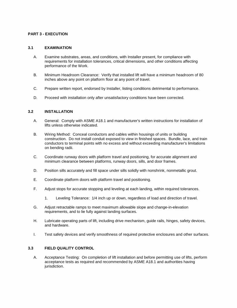
PART 3 - EXECUTION
3.1 EXAMINATION
A. Examine substrates, areas, and conditions, with Installer present, for compliance with
requirements for installation tolerances, critical dimensions, and other conditions affecting performance of the Work.
B. Minimum Headroom Clearance: Verify that installed lift will have a minimum headroom of 80
inches above any point on platform floor at any point of travel.
C. Prepare written report, endorsed by Installer, listing conditions detrimental to performance.
D. Proceed with installation only after unsatisfactory conditions have been corrected.
3.2 INSTALLATION
A. General: Comply with ASME A18.1 and manufacturer's written instructions for installation of
lifts unless otherwise indicated.
B. Wiring Method: Conceal conductors and cables within housings of units or building
construction. Do not install conduit exposed to view in finished spaces. Bundle, lace, and train conductors to terminal points with no excess and without exceeding manufacturer's limitations on bending radii.
C. Coordinate runway doors with platform travel and positioning, for accurate alignment and
minimum clearance between platforms, runway doors, sills, and door frames.
D. Position sills accurately and fill space under sills solidly with nonshrink, nonmetallic grout.
E. Coordinate platform doors with platform travel and positioning.
F. Adjust stops for accurate stopping and leveling at each landing, within required tolerances.
1. Leveling Tolerance: 1/4 inch up or down, regardless of load and direction of travel.
G. Adjust retractable ramps to meet maximum allowable slope and change-in-elevation requirements, and to lie fully against landing surfaces.
H. Lubricate operating parts of lift, including drive mechanism, guide rails, hinges, safety devices,
and hardware.
I. Test safety devices and verify smoothness of required protective enclosures and other surfaces.
3.3 FIELD QUALITY CONTROL
A. Acceptance Testing: On completion of lift installation and before permitting use of lifts, perform
acceptance tests as required and recommended by ASME A18.1 and authorities having jurisdiction.

B. Operating Test: In addition to acceptance testing, load lifts to rated capacity and operate continuously for 30 minutes between lowest and highest landings served. Readjust stops, signal equipment, and other devices for accurate stopping and operation of system.
C. Advise Owner, Owner, and authorities having jurisdiction in advance of dates and times tests
are to be performed on lifts.
3.4 MAINTENANCE SERVICE
A. Initial Maintenance Service: Beginning at Substantial Completion, maintenance service shall
include 12 months' full maintenance by skilled employees of lift Installer. Include quarterly preventive maintenance, repair or replacement of worn or defective components, lubrication, cleaning, and adjusting as required for proper lift operation. Parts and supplies shall be manufacturer's authorized replacement parts and supplies.
3.5 DEMONSTRATION
A. Engage a factory-authorized service representative to train Owner's maintenance personnel to
adjust, operate, and maintain lifts. Include a review of emergency systems and emergency procedures to be followed at time of operational failure and other building emergencies.
B. Check operation of lifts with Owner's personnel present and before date of Substantial
Completion. Determine that operating systems and devices are functioning properly.
C. Check operation of lifts with Owner's personnel present not more than one month before end of
warranty period. Determine that operating systems and devices are functioning properly.
END OF SECTION