142685392 huawei antenna
DESCRIPTION
Huawey RF AntennasTRANSCRIPT

Huawei Antenna & Antenna Line Products Catalogue
2013 01 Issue
HUAWEI TECHNOLOGIES CO., LTD.

Huawei Network Antenna, Leading to Mobile Broadband Era
Huawei' VisionTo focus on customers' challenges and needs in MBB Era by providing best network antenna solutions based on deep insight into network.
Industry-Leading Antenna Solutions
Antennas for Optimal Network Performance• Huawei is a pioneer in designing antenna for better network performance. All antennas are analyzed and optimized using network simulation systems. This makes it possible for Huawei antennas to provide enhanced network performance (10% better than traditional antennas).
S• upporting Full Range of Frequency Bands and Reducing TCOHuawei provides more than 100 types of mainstream antennas covering frequency ranges from 698 MHz to 2690 MHz, with the support from single band to penta-band. Huawei's antennas lead the industry in terms of width, weight, wind load and "green upgrade" support to minimize tower modernization costs and rental fees.
Easy Maintenance for Reducing OPEX• Huawei's EasyRET solution for antennas eliminates extra sites visit due to incorrect
Huawei has been dedicated to participate in mobile communications for over 20 years. and always absorbed to design and produce Base Station Antenna with some 300 experts and engineers in five R&D centers based in China, Germany, Canada and USA. Huawei has been awarded more than 100 BTS antenna patents and has membership in more than 50 standardization organizations. Thanks to Huawei's experience as well as its industry-leading network designs, performance simulation platforms, and precise 3D spherical antenna near-field testing system, Huawei is capable of providing network antennas with optimal network performance.

installation and shortens installation time by 95%. RCUs Integrated improve reliability while reducing antenna installation and RCU maintenance costs by 80%. Imbedded RCU software requires no configuration, and improves service provisioning efficiency by approximately 95%.
Flexible MIMO Configurations• Flexible configurations are available for multi-band(700/ 800/1800/1900/2100/2300/2600 MHz) for LTE in 2T2R/2T4R/ 4T4R/4T8R/8T8R MIMO. One time deployment supports long-term evolution.
Supporting Evolution to AAS• The integration of Radio Unit within the antenna is the elimination of several components like cables, connectors, and mounting hardware and an overall reduction in the physical tower space required. Huawei can provide an industry-leading active antenna
system (AAS) to handle dynamic capacity requirements, and the aesthetics of the site can be improved and wind load reduced by integrating RRU functionality into the antenna.
High-Performing TMA and Easy O&M• Huawei can provide Dual Tower Mounted Amplifier(DTMA) and Dualband Tower Mounted Amplifier with less noise figure, lower insertion loss and PIM, which improves uplink receiver sensitivity of radio system. Huawei is also the only vendor in the world to provide remote gain control as well as electrical labeling (essential to TMA asset management).
Huawei is committed to improving its customers' Wireless Communications Network capacities over the long-term. We look forward to cooperating with you in delivering optimal network performance using our antenna solutions.

Huawei Antenna & Antenna Line Products Catalogue >>
Huawei's SG128 spherical near field testing system - the world's most
advanced antenna testing system:High-performing ultra-broadband dual-polarization probes•
Five-axis precision turret for military use (can be rotated with 0.01 degree precision)•
Albatross high-performing shielded room from Germany•
AEMI radar absorbing materials from the US•
Precise and stable equipment imported from industry-leading countries•
Infrared laser for calibration and dedicated installation support•
Full series of installation poles•
Industry-leading temperature control technology•

Type Reference Method Condition Duration Parameters Tested
Low Temperature Exposure
ETSI 300 019 - 2 - 4 IEC 60068 - 2 - 1 -55 16hVisual/physical exam VSWR ISO and PIM (pre and post)
High Temperature Exposure
ETSI 300 019 - 2 - 4 IEC 60068 - 2 - 2 +70 16hVisual/physical exam VSWR ISO and PIM (pre and post)
Temperature Cycling
ETSI 300 019 - 2 - 4 IEC 60068 - 2 - 14 -55ºC/+70ºC 5cycles,50hVisual/physical exam VSWR ISO and PIM (pre and post)
Humidity ETSI 300 019 - 2 - 4 IEC 60068 - 2 - 30 +25ºC/+55ºC @ 95% RH 10cycles,240hVisual/physical exam VSWR ISO and PIM (pre and post)
Wind Loading ETSI 300 019 - 2 - 4 IEC 721 - 3 - 4Simulated constant force of
200 km/h wind3surfaces,144h
Visual/physical exam VSWR ISO and PIM (pre and post)
Vibration ETSI 300 019 - 2 - 4 IEC 60068 - 2 - 6sinusoidal 6.15mm,10m/
s2,2-9HZ 9HZ-200HZ 3axes×5
sweep cyclesVisual/physical exam VSWR ISO and PIM (pre and post)
Transportation Vibration
ETSI 300 019 - 2 - 4 IEC 60068 - 2 - 64 Truck level 3 3 axes,90minVisual/physical exam VSWR ISO and PIM (pre and post)
Shocks(without package)
ETSI 300 019 - 2 - 4 IEC 60068 - 2 - 27 300 m/s2,6ms pulse width 72sVisual/physical exam VSWR ISO and PIM (pre and post)
shocks(with package)
ETSI 300 019 - 2 - 2 IEC 60068 - 2 - 27 300 m/s2,6ms pulse width 72sVisual/physical exam VSWR ISO and PIM (pre and post)
Drop(with package)
ETSI 300 019 - 2 - 2 ISO 12048 6surfaces/4Angles/3Edges 13 dropsVisual/physical exam VSWR ISO and PIM (pre and post)
Rain(in water chamber)
ETSI 300 019 - 2 - 4 IEC 60068 - 2 - 18 0.067m3/min,5r/min 2hVisual/physical exam VSWR ISO and PIM (pre and post)
Wind Driven Rain GR - 487 - COREMIL - STD - 810 Method 506.3
150mm/h,31m/s,0.5mm-4.5mm,45°
4surfaces,more than 120min
Visual/physical exam VSWR ISO and PIM (pre and post)
Salt Fog(Continuous)
ETSI 300 019 - 2 - 4 IEC 60068 - 2 - 11 5%NaCl mist @+40ºC 1000hVisual/physical exam VSWR ISO and PIM (pre and post)
Salt Fog(Cyclic)
ETSI 300 019 - 2 - 4 IEC 60068 - 2 - 525%NaCl mist
@+15/+40ºC,93% RH 10 cycles,240h
Visual/physical exam VSWR ISO and PIM (pre and post)
Solar(UV) Exposure
ETSI 300 019 - 2 - 4 IEC 60068 - 2 - 5 1120W/s2 @+40ºC24h/
cycle,56daysVisual/physical exam VSWR ISO and PIM (pre and post)
Dust and sand ETSI 300 019 - 2 - 4 IEC 60068 - 2 - 68150um-850um,1g/m3,20m/
s @+70ºC,RH<30%8h
Visual/physical exam VSWR ISO and PIM (pre and post)
Huawei Antenna & Antenna Line Products Catalogue >>
Huawei Antenna Test Standard
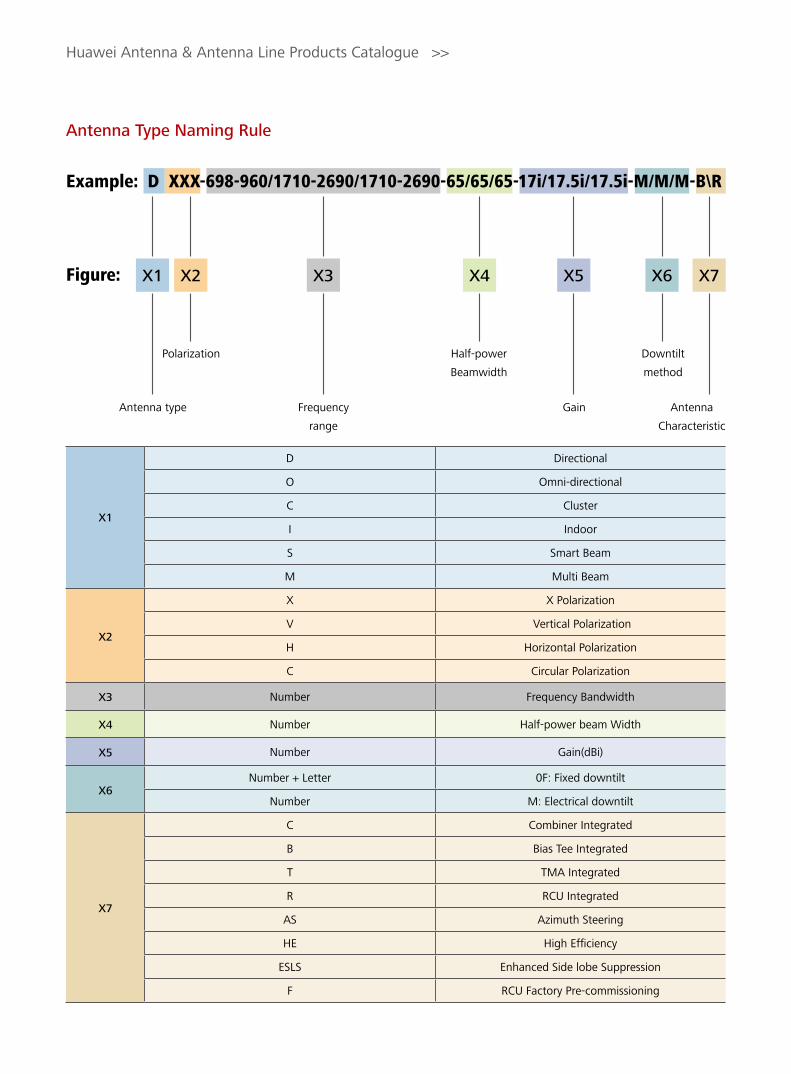
Antenna Type Naming Rule
Huawei Antenna & Antenna Line Products Catalogue >>
Figure:
D Directional
O Omni-directional
C Cluster
I Indoor
S Smart Beam
M Multi Beam
X X Polarization
V Vertical Polarization
H Horizontal Polarization
C Circular Polarization
Number Frequency Bandwidth
Number Half-power beam Width
Number Gain(dBi)
Number + Letter 0F: Fixed downtilt
Number M: Electrical downtilt
C Combiner Integrated
B Bias Tee Integrated
T TMA Integrated
R RCU Integrated
AS Azimuth Steering
HE High Efficiency
ESLS Enhanced Side lobe Suppression
F RCU Factory Pre-commissioning
X1
X2
X4
X6
X3
X5
Antenna
Characteristic
Frequency
range
GainAntenna type
Downtilt
method
Polarization Half-power
Beamwidth
X1 X2 X4 X6X3 X5 X7
X7
Example: D XXX-698-960/1710-2690/1710-2690-65/65/65-17i/17.5i/17.5i-M/M/M-B\R

(Optional) Version
Function
Identification
Product type
Figure shows naming rules for models
Huawei Antenna & Antenna Line Products Catalogue >>
Figure:
Antenna Example: ADU451807v01
RCU Example: ARCU01109
v01/v02 version(or blank)
v01/v02 version(or blank)
Frequency info+ Polarization + Gain
RCU + Protocol (AISG1.1/2.0 )
Identify different characters in ascending order
Identify different characters in ascending order
Antenna Products
ALD Products
1
A
A
2 3 4 5 6
D U 4 5 1 8
R C U 0 1 1
10 11 12
v 0 1
v 0 1
8 9
0 7
0 9
TMA Example: ATA261100
v01/v02 version(or blank)
TA(TMA short) + Frequency + Protocol(AISG1.1/2.0)
Identify different characters in ascending order
ALD Products
A T A 2 6 1 1 v 0 10 0
Combiner Example: ACOMD2H00
v01/v02 version(or blank)
Combiner+Channel+Unit Number+DC bypass properpies
Identify different characters in ascending order
ALD Products
A C O M D 2 H v 0 10 0
Notes:45: single-band 450–470 MHz antennas79: single-band 790–960 MHz antennas90: single-band 806–960 MHz antennas19: single-band 1710–2200 MHz or 1710–2170 MHz antennas25: single-band 2300–2700 MHz antennas26: single-band 1710–2690 MHz antennasDU: dual-band antennasTR: tri-band antennasQU: quad-band antennasPE: penta-band antennas80: TMAs working at 800 MHz90: TMAs working at 900 MHz18: TMAs working at 1800 MHz21: TMAs working at 2100 MHz26: TMAs working at 2600 MHzDU: dual-band TMAs

ContentsProduct Portfolio
A. Huawei Network Antennas C. Accessories for RET Systems
B. Antenna Line Products D. Mounting Instructions
B - 1. Tower Mounted Amplifiers
B - 2. Combiners
D - 1. MET Installation Guide
D - 2. RET Installation Guide
D - 3. FET Installation Guide
D - 4. Tri-sector Cluster Installation Guide
A - 1. FET Antenna
A - 2. Single Band Antenna
A - 3. Dual-band Antenna
A - 4. Triple-band Antenna
A - 5. Quad-band Antenna
A - 6. Penta-band Antenna
A - 7. TDD Antenna
A - 8. Cluster Antenna
A - 9. Antenna Integrated Bracket
C - 1. Remote Control Unit (RCU)
C - 2. Bias Tee (BT)
C - 3. Smart Bias Tee (SBT)
C - 4. AISG Connecting Cables
C - 5. Portable Control Unit (PCU)
Huawei Antenna & Antenna Line Products Catalogue >>
i
Contents

IndexA. Huawei Network Antennas
Huawei Antenna & Antenna Line Products Catalogue >>
A - 1. FET Antenna
Frequency Range (MHz)
Polarization3dB Horizontal beam width (°)
Gain (dBi) Electrical
downtilt (°) Tilt
MethodConnector Dimension (mm) Model Page
450-470 v 360 9 0 FET1 x 7/16 DIN
Female Φ52 x 3316 A45VP0900 1
450-470 x 65 15 0 FET2 x 7/16 DIN
Female 2042 x 486 x 98 A45451500 2
806-960 x 65 15 0 FET2 x 7/16 DIN
Female 1322 x 289 x 85 A90451500 3
806-960 x 65 15 3 FET2 x 7/16 DIN
Female 1322 x 289 x 85 A90451505 4
806-960 x 65 15 6 FET2 x 7/16 DIN
Female 1322 x 289 x 85 A90451501 5
806-960 x 65 15.3 0 FET2 x 7/16 DIN
Female 1312 x 295 x 126 A90451502 6
806-960 x 65 15.3 6 FET2 x 7/16 DIN
Female 1312 x 295 x 126 A90451503 7
806-960 x 65 17 0 FET2 x 7/16 DIN
Female 1932 x 289 x 85 A90451700 8
806-960 x 65 17 3 FET2 x 7/16 DIN
Female 1932 x 289 x 85 A90451705 9
806-960 x 65 18 0 FET2 x 7/16 DIN
Female 2572 x 289 x 85 A90451800 10
806-960 x 65 18 3 FET2 x 7/16 DIN
Female 2572 x 289 x 85 A90451805 11
806-960 x 65 18 6 FET2 x 7/16 DIN
Female 2572 x 289 x 85 A90451801 12
806-960 x 90 17 0 FET2 x 7/16 DIN
Female 2526 x 268 x 125 A90451600 13
806-960 x 90 17 3 FET2 x 7/16 DIN
Female 2526 x 268 x 125 A90451706 14
790-960 x 65 17 0 FET2 x 7/16 DIN
Female 1936 x 260 x 135 A90451702v01 16
790-960 x 65 17 3 FET2 x 7/16 DIN
Female 1936 x 260 x 135 A90451705v01 18
790-960 x 65 17 6 FET2 x 7/16 DIN
Female 1936 x 260 x 135 A90451709 20
790-960 x 65 18 0 FET2 x 7/16 DIN
Female 2535 x 259 x 135 A90451802v01 22
790-960 x 65 18 3 FET2 x 7/16 DIN
Female 2535 x 259 x 135 A90451805v01 24
1710-2170 x 90 17 0 FET2 x 7/16 DIN
Female 1306 x 155 x 79 A19451704 26
1710-2170 x 90 17 3 FET2 x 7/16 DIN
Female 1306 x 155 x 79 A19451705 28
iiIn
dex

Huawei Antenna & Antenna Line Products Catalogue >>
iii
Index
Frequency Range (MHz)
Polarization3dB Horizontal beam width (°)
Gain (dBi) Electrical
downtilt (°) Tilt
MethodConnector Dimension (mm) Model Page
806-960 x 90 17 2-9.5 MET2 x 7/16 DIN
Female 2526 x 268 x 125 A90451704 44
790-960 x 65 15 0-14 MET2 x 7/16 DIN
Female 1356 x 259 x 135 A79451500v01 45
790-960 x 65 16.5 0-12 MET2 x 7/16 DIN
Female 1936 x 259 x 135 A79451600v01 46
790-960 x 65 17.5 0-10 MET2 x 7/16 DIN
Female2535 x 259 x 135 A79451700v01 48
698-960 x 65 15 0-14 MET2 x 7/16 DIN
Female 1356 x 259 x 135 **A70451501 50
698-960 x 65 16.5 0-12 MET2 x 7/16 DIN
Female 1936 x 259 x 135 **A70451600 51
698-960 x 65 17.5 0-10 MET2 x 7/16 DIN
Female2535 x 259 x 135 **A70451700 52
698-960 x 90 15 0-12 MET2 x 7/16 DIN
Female1936 x 259 x 135 **A70451500 53
1710-2170 x 90 17 2-10 MET2 x 7/16 DIN
Female 1306 x 155 x 79 A19451703 54
1710-2170 x 33 21 2-10 MET2 x 7/16 DIN
Female 1318 x 289 x 85 A19452101 55
1710-2200 x 65 15.5 0–12 MET2 x 7/16 DIN
Female702 x 155 x 89 A19451505 56
1710-2200 x 65 18 0-10 MET2 x 7/16 DIN
Female1311 x 155 x 89 A19451811 58
A - 2. Single Band Antenna
** Preliminary Issue
Frequency Range (MHz)
Polarization3dB Horizontal beam width (°)
Gain (dBi) Electrical
downtilt (°) Tilt
MethodConnector Dimension (mm) Model Page
1710-2170 x 65 18 2 FET2 x 7/16 DIN
Female 1306 x 155 x 79 A19451801 30
1710-2170 x 33 21 0 FET2 x 7/16 DIN
Female 1318 x 289 x 85 A19452102 31
1710-2170 x 65 21 0 FET2 x 7/16 DIN
Female 2170 x 155 x 79 A19452100 32
1710-2170 x 65 21 2 FET2 x 7/16 DIN
Female 2170 x 155 x 79 A19452103 33
1710-2200 x 65 15.5 3 FET2 x 7/16 DIN
Female 702 x 155 x 89 A19451601 34
1710-2200 x 65 15.5 6 FET2 x 7/16 DIN
Female 702 x 155 x 89 A19451602 36
1710-2200 x 65 18 0 FET2 x 7/16 DIN
Female 1311 x 155 x 89 A19451800v01 38
1710-2200 x 65 18 3 FET2 x 7/16 DIN
Female 1311 x 155 x 89 A19451810v01 40
1710-2200 x 65 18 6 FET2 x 7/16 DIN
Female 1311 x 155 x 89 A19451802v01 42

Huawei Antenna & Antenna Line Products Catalogue >>
ivIn
dex
** Preliminary Issue
Frequency Range (MHz)
Polarization3dB Horizontal beam width (°)
Gain (dBi) Electrical
downtilt (°) Tilt
MethodConnector Dimension (mm) Model Page
1710-2200 x 65 18 0-10 EasyRET2 x 7/16 DIN
Female 1315 x 155 x 89 A194518R0 60
1710-2200 x 65 19.5 0-6 MET2 x 7/16 DIN
Female1954 x 155 x 89 A19451902 62
1710-2690 x 65 16 0-14 MET2 x 7/16 DIN
Female790 x 155 x 109 **A26451500 64
1710-2690 x 65 18 0-12 MET2 x 7/16 DIN
Female 1365 x 155 x 109 **A26451800v01 65
1710-2690 x 65 18 0-12 EasyRET2 x 7/16 DIN
Female 1365 x 155 x 109 **A264518R0 67
1710-2690 x 65 19.5 0-8 MET2 x 7/16 DIN
Female1690 x 155 x 109 **A26451900v01 69
** Preliminary Issue
Frequency Range (MHz)
Polarization3dB Horizontal beam width (°)
Gain (dBi) Electrical
downtilt (°) Tilt
MethodConnector Dimension (mm) Model Page
790-862/880-960
xx 65/65 14.5/15 0-14/0-14 EasyRET4 x 7/16 DIN
Female1536 x 349 x 166 **ADU4515R0 70
790-862/880-960
xx 65/65 16/16.5 0-12/0-12 EasyRET4 x 7/16 DIN
Female1999 x 259 x 135 ADU4516R0 72
790-862/880-960
xx 65/65 17/17.5 0-10/0-10 EasyRET4 x 7/16 DIN
Female 2538 x 259 x 135 ADU4517R0 74
790-960/1710-2180
xx 65/65 15/17.5 0-14/0-10 MET4 x 7/16 DIN
Female1360 x 259 x 135 ADU451503 76
790-960/1710-2180
xx 65/65 16.5/18.5 0-12/0-8 MET4 x 7/16 DIN
Female1936 x 259 x 135 ADU451602v01 78
790-960/1710-2180
xx 65/65 16.5/18.5 0-12/0-8 EasyRET4 x 7/16 DIN
Female 1936 x 259 x 135 ADU4518R3 80
790-960/1710-2180
xx 65/65 17.5/18.5 0-10/0-8 MET4 x 7/16 DIN
Female2535 x 259 x 135 ADU451807v01 82
790-960/1710-2180
xx 65/65 17.5/18.5 0-10/0-8 EasyRET4 x 7/16 DIN
Female 2535 x 259 x 135 ADU4518R0 84
790-960/1710-2180
x 65/65 15/17.5 0-14/0-10MET+
Combiner2 x 7/16 DIN
Female1360 x 259 x 135 **ADU4517C0 86
790-960/1710-2180
x 65/65 16.5/18.5 0-12/0-8MET+
Combiner2 x 7/16 DIN
Female1936 x 259 x 135 **ADU4518C1 87
790-960/1710-2180
x 65/65 17.5/18.5 0-10/0-8MET+
Combiner2 x 7/16 DIN
Female2535 x 259 x 135 ADU4518C0 88
790-960/1710-2180
xx 65/65 16.5/18.5 0-12/0-8MET-ESLS
4 x 7/16 DIN Female
1936 x 259 x 135 ADU451820 90
790-960/1710-2180
xx 65/65 17.5/18.5 0-10/0-8MET-ESLS
4 x 7/16 DIN Female
2535 x 259 x 135 ADU451821 92
790-960/1710-2690
xx 65/65 15/17.5 0-14/0-10 MET4 x 7/16 DIN
Female1450 x 298 x 148 **ADU451716 94
A - 3. Dual-band Antenna
Huawei Antenna & Antenna Line Products Catalogue >>
v
Index
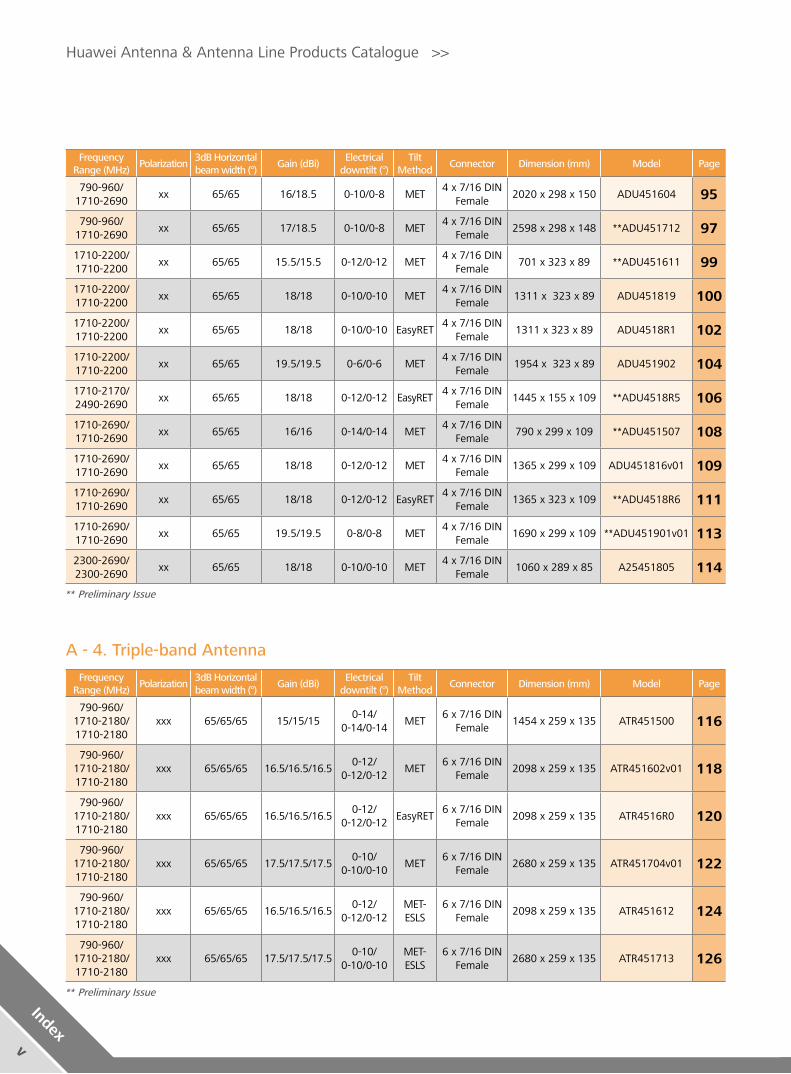
Frequency Range (MHz)
Polarization3dB Horizontal beam width (°)
Gain (dBi) Electrical
downtilt (°) Tilt
MethodConnector Dimension (mm) Model Page
790-960/1710-2180/1710-2180
xxx 65/65/65 15/15/150-14/
0-14/0-14MET
6 x 7/16 DIN Female
1454 x 259 x 135 ATR451500 116
790-960/1710-2180/1710-2180
xxx 65/65/65 16.5/16.5/16.5 0-12/
0-12/0-12MET
6 x 7/16 DIN Female
2098 x 259 x 135 ATR451602v01 118
790-960/1710-2180/1710-2180
xxx 65/65/65 16.5/16.5/16.5 0-12/
0-12/0-12EasyRET
6 x 7/16 DIN Female
2098 x 259 x 135 ATR4516R0 120
790-960/1710-2180/1710-2180
xxx 65/65/65 17.5/17.5/17.50-10/
0-10/0-10MET
6 x 7/16 DIN Female
2680 x 259 x 135 ATR451704v01 122
790-960/1710-2180/1710-2180
xxx 65/65/65 16.5/16.5/16.50-12/
0-12/0-12MET-ESLS
6 x 7/16 DIN Female
2098 x 259 x 135 ATR451612 124
790-960/1710-2180/1710-2180
xxx 65/65/65 17.5/17.5/17.50-10/
0-10/0-10MET-ESLS
6 x 7/16 DIN Female
2680 x 259 x 135 ATR451713 126
A - 4. Triple-band Antenna
** Preliminary Issue
Frequency Range (MHz)
Polarization3dB Horizontal beam width (°)
Gain (dBi) Electrical
downtilt (°) Tilt
MethodConnector Dimension (mm) Model Page
790-960/1710-2690
xx 65/65 16/18.5 0-10/0-8 MET4 x 7/16 DIN
Female2020 x 298 x 150 ADU451604 95
790-960/1710-2690
xx 65/65 17/18.5 0-10/0-8 MET4 x 7/16 DIN
Female2598 x 298 x 148 **ADU451712 97
1710-2200/1710-2200
xx 65/65 15.5/15.5 0-12/0-12 MET4 x 7/16 DIN
Female701 x 323 x 89 **ADU451611 99
1710-2200/1710-2200
xx 65/65 18/18 0-10/0-10 MET4 x 7/16 DIN
Female1311 x 323 x 89 ADU451819 100
1710-2200/1710-2200
xx 65/65 18/18 0-10/0-10 EasyRET4 x 7/16 DIN
Female 1311 x 323 x 89 ADU4518R1 102
1710-2200/1710-2200
xx 65/65 19.5/19.5 0-6/0-6 MET4 x 7/16 DIN
Female1954 x 323 x 89 ADU451902 104
1710-2170/2490-2690
xx 65/65 18/18 0-12/0-12 EasyRET4 x 7/16 DIN
Female1445 x 155 x 109 **ADU4518R5 106
1710-2690/1710-2690
xx 65/65 16/16 0-14/0-14 MET4 x 7/16 DIN
Female790 x 299 x 109 **ADU451507 108
1710-2690/1710-2690
xx 65/65 18/18 0-12/0-12 MET4 x 7/16 DIN
Female1365 x 299 x 109 ADU451816v01 109
1710-2690/1710-2690
xx 65/65 18/18 0-12/0-12 EasyRET4 x 7/16 DIN
Female1365 x 323 x 109 **ADU4518R6 111
1710-2690/1710-2690
xx 65/65 19.5/19.5 0-8/0-8 MET4 x 7/16 DIN
Female 1690 x 299 x 109 **ADU451901v01 113
2300-2690/2300-2690
xx 65/65 18/18 0-10/0-10 MET4 x 7/16 DIN
Female 1060 x 289 x 85 A25451805 114
** Preliminary Issue

Huawei Antenna & Antenna Line Products Catalogue >>
viIn
dex
A - 5. Quad-band Antenna
Frequency Range (MHz)
Polarization3dB Horizontal beam width (°)
Gain (dBi) Electrical
downtilt (°) Tilt
MethodConnector Dimension (mm) Model Page
790-960/ 1710-2690/ 1710-2170/ 2490-2690
xxxx 65/65/65/65 16/18/18/180-10/0-8/0-8/0-8
EasyRET8 x 7/16 DIN
Female 1999 x 349 x 166 **AQU4518R0 142
790-960/1710-2690/1710-2170/2490-2690
xxxx 65/65/65/65 17/18/18/180-10/0-8/0-8/0-8
EasyRET8 x 7/16 DIN
Female 2593 x 349 x 166 **AQU4518R1 144
** Preliminary Issue
** Preliminary Issue
Frequency Range (MHz)
Polarization3dB Horizontal beam width (°)
Gain (dBi) Electrical
downtilt (°) Tilt
MethodConnector Dimension (mm) Model Page
790-960/1710-2180/1710-2180
xxx 65/65/65 17.5/17.5/17.50-10/
0-10/0-10EasyRET
6 x 7/16 DIN Female
2680×259×135 ATR4517R0 128
790-960/ 1710-2690/ 1710-2690
xxx 65/65/65 16/18/180-10/
0-8/0-8EasyRET
6 x 7/16 DIN Female
1999 x 349 x 166 **ATR4518R4 130
790-960/ 1710-2690/ 1710-2690
xxx 65/65/65 17/18/180-10/
0-8/0-8EasyRET
6 x 7/16 DIN Female
2593 x 349 x 166 **ATR4518R7 132
790-960/ 1710-2690/ 1710-2690
xxx 65/65/65 15/17.5/17.50-14/
0-10/0-10MET
6 x 7/16 DIN Female
1472 x 349 x 166 **ATR451709 134
790-960/ 1710-2690/ 1710-2690
xxx 65/65/65 16/18/180-10/
0-8/0-8MET
6 x 7/16 DIN Female
1999 x 349 x 166 **ATR451606 135
790-960/ 1710-2690/ 1710-2690
xxx 65/65/65 17/18/180-10/
0-8/0-8MET
6 x 7/16 DIN Female
2593 x 349 x 166 **ATR451607 136
698-960/ 1710-2690/ 1710-2690
xxx 65/65/65 17/17.5/17.50-10/
0-8/0-8EasyRET+
SBT6 x 7/16 DIN
Female 2685 x 349 x 148 **ATR4518R9 137
1710-2690/ 1710-2170/ 2490-2690
xxx 65/65/65 18/18/180-10/
0-10/0-10EasyRET
6 x 7/16 DIN Female
1445 x 299 x 109 **ATR4518R3 139
1710-2690/ 1710-2690/ 1710-2690
xxx 65/65/65 18/18/180-12/
0-12/0-12MET
6 x 7/16 DIN Female
1445 x 449 x 115 **ATR451714 141
A - 6. Penta-band Antenna
Frequency Range (MHz)
Polarization3dB Horizontal beam width (°)
Gain (dBi) Electrical
downtilt (°) Tilt
MethodConnector Dimension (mm) Model Page
698-960/ 1710-2690/ 1710-2690/ 1710-2690/ 1710-2690
xxxxx65/65/
65/65/6517/17.5/
17.5/17/17
0-10/0-10/0-10/0-10/
0-10EasyRET
10 x 7/16 DIN Female
2695 x 349 x 166 **APE4517R2 146
** Preliminary Issue

Frequency Range (MHz)
Polarization3dB Horizontal beam width (°)
Gain (dBi) Electrical
downtilt (°) Tilt
MethodConnector Dimension (mm) Model Page
1710-2690 x 65 18 2-12 MET3 x 2 x 7/16 DIN Female
1793 x Φ230 & Φ250
A264518S0 166
A - 8. Cluster Antenna
Frequency Range (MHz)
Polarization3dB Horizontal beam width (°)
Gain (dBi) Electrical
downtilt (°) Tilt
MethodConnector Dimension (mm) Model Page
1880-2690 x 90 16 0 FET 9 x N Female 1396 x 319 x 116 **ATD451600 148
1880-2690 x 90 16 3 FET 9 x N Female 1396 x 319 x 116 **ATD451601 150
1880-2690 x 90 16 6 FET 9 x N Female 1396 x 319 x 116 **ATD451602 152
1880-2690 x 90 16 9 FET 9 x N Female 1396 x 319 x 116 **ATD451603 154
1880-2690 x 90 16 0MET+
Combiner
4 x Circular Multipin
Connnector1396 x 319 x 116 **ATD4516C0 156
1880-2690 x 90 16 3MET+
Combiner
4 x Circular Multipin
Connnector1396 x 319 x 116 **ATD4516C1 158
1880-2690 x 90 16 6MET+
Combiner
4 x Circular Multipin
Connnector1396 x 319 x 116 **ATD4516C2 160
1880-2690 x 90 16 9MET+
Combiner
4 x Circular Multipin
Connnector1396 x 319 x 116 **ATD4516C3 162
2300-2700 x 60 18 2-10 MET 2 x N Female 1060 x 155 x 79 A25451804 164
2300-2700/2300-2700
xx 65/65 18/18 2-10 MET 4 x N Female 1060 x 289 x 85 A25451803 165
A - 7. TDD Antenna
** Preliminary Issue
Huawei Antenna & Antenna Line Products Catalogue >>
vii
Index
Bracket typeAntenna Width
ReqiredWeight (Kg) Dimension (mm) Model Page
TSC-S (3 Sector Clamp-Small)
<280mm 5.8 88.9mm (3.5inch) ASMC00001
168TSC-M (3 Sector Clamp-Medium)
<380mm 6.3 114.3mm (4.5inch) ASMC00002
TSC-L (3 Sector Clamp-Large)
<400mm 6.6 139.7mm (5.5inch) ASMC00003
A - 9. Antenna Integrated Bracket
**AISG Color Coding Standard 170

Description Frequency Range (MHz) AISG type Gain (dB) Dimension (mm) Model Page
DD800MHz
RX : 832 - 862 AISG v1.1 8 - 16
(0.5 dB Step) 190 x 240 x 120
ATA801100
172TX : 791 - 821 AISG v2.0 ATA802000
EGSM 900MHz SUBBAND
RX : 880 - 905 AISG v1.1 8 - 16
(0.5 dB Step)198 x 308 x 70.5
ATA901102
175TX : 925 - 950 AISG v2.0 ATA902002
EGSM 900MHz
RX : 880 - 915 AISG v1.1 8 - 16
(0.5 dB Step) 248 x 324 x 75.5
ATA901101
178TX : 925 - 960 AISG v2.0 ATA902001
PGSM 900MHz
RX : 890 - 915 AISG v1.1 8 - 16
(0.5 dB Step)198 x 308 x 70.5
ATA901103
181TX : 935 - 960 AISG v2.0 ATA902003
1800MHz
RX : 1710 - 1785 AISG v1.1
12 160 x 220 x 100
ATA181101
184TX : 1805 - 1880 AISG v2.0 ATA182001
2100MHz
RX : 1920 - 1980 AISG v1.1
12 160 x 205 x 54.5
ATA211101
187TX : 2110 - 2170 AISG v2.0 ATA212001
2600MHz
RX : 2500 - 2570 AISG v1.1
12 160 x 210 x 54.5
ATA261100
190TX : 2620 - 2690 AISG v2.0 ATA262000
900MHz Bypass 1800MHz
RX : 880 - 915
AISG v2.08-16
(0.5 dB Step)248 x 324 x 100 **ATA902004 193
TX : 925 - 960
2100MHz Bypass 900MHz
RX : 1920 - 1980
AISG v2.0 12 228 x 205 x 54.5 **ATA212004 196TX : 2110 - 2170
2100MHz Bypass 1800MHz
RX : 1920 - 1980
AISG v2.0 12 175 x 245 x 100 **ATA212002 199TX : 2110 - 2170
2100MHz Bypass 900/1800MHz
RX : 1920 - 1980
AISG v2.0 12 224 x 312 x 95 **ATA212003 202TX : 2110 - 2170
** Preliminary Issue
B. Antenna Line Products
B - 1. Tower Mounted Amplifiers
Huawei Antenna & Antenna Line Products Catalogue >>
viiiIn
dex
** Preliminary Issue
** Preliminary Issue
Catagery Pass Band (MHz)Max. Input power (W)
DC-BypassIntermodulation
(dBm)Dimension (mm) Model Page
Dual-band Combiner
Band 1 : 790 - 862 200880 - 960MHz
DC-bypass< -110
Double Unit: 180 x 210 x 107
ACOMD2H09 217Band 2 : 880 - 960 200
Band 1 : 790 - 862 200880 - 960MHz
DC-bypass< -117
Double Unit: 180 x 210 x 107
ACOMD2H04 220Band 2 : 880 - 960 200
Band 1 : 790 - 862 200
All DC-bypass < -110 Double Unit:
180 x 210 x 107 **ACOMD2H18 223
Band 2 : 880 - 960 200
Band 1 : 790 - 862 200
All DC-bypass < -117Double Unit:
180 x 210 x 107 **ACOMD2H15 226
Band 2 : 880 - 960 200
Band 1 : 790 - 862 300
All DC-bypass < -117Double Unit:
220 x 210 x 115 **ACOMD2H14 229
Band 2 : 880 - 2200 300
Band 1 : 698 - 960 3001710 - 2200MHz
DC-bypass< -110
Double Unit: 130 x 190 x 105
ACOMD2H11 232Band 2 : 1710 - 2200 300
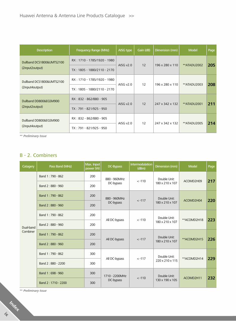
B - 2. Combiners
Huawei Antenna & Antenna Line Products Catalogue >>
ix
Index
Description Frequency Range (MHz) AISG type Gain (dB) Dimension (mm) Model Page
Dullband DCS1800&UMTS2100
(2input2output)
RX : 1710 - 1785/1920 - 1980
AISG v2.0 12 196 x 280 x 110 **ATADU2002 205TX : 1805 - 1880/2110 - 2170
Dullband DCS1800&UMTS2100
(2input4output)
RX : 1710 - 1785/1920 - 1980
AISG v2.0 12 196 x 280 x 110 **ATADU2003 208TX : 1805 - 1880/2110 - 2170
Dullband DD800&EGSM900
(2input2output)
RX : 832 - 862/880 - 905
AISG v2.0 12 247 x 342 x 132 **ATADU2001 211TX : 791 - 821/925 - 950
Dullband DD800&EGSM900
(2input4output)
RX : 832 - 862/880 - 905
AISG v2.0 12 247 x 342 x 132 **ATADU2005 214TX : 791 - 821/925 - 950

Catagery Pass Band (MHz)Max. Input power (W)
DC-BypassIntermodulation
(dBm)Dimension (mm) Model Page
Dual-band Combiner
Band 1 : 698 - 960 3001710 - 2200MHz
DC-bypass< -117
Double Unit: 130 x 190 x 105
ACOMD2H10 235Band 2 : 1710 - 2200 300
Band 1 : 698 - 960 300
All DC-bypass < -110Double Unit:
130 x 190 x 105 **ACOMD2H19 238
Band 2 : 1710 - 2200 300
Band 1 : 698 - 960 3002490 - 2700MHz
DC-bypass< -110
Double Unit: 130 x 190 x 105
ACOMD2H13 241Band 2 : 2490 - 2700 300
Band 1 : 698 - 960 3002490 - 2700MHz
DC-bypass< -117
Double Unit: 130 x 190 x 105
ACOMD2H12 244Band 2 : 2490 - 2700 300
Band 1 : 698 - 960 300
All DC-bypass < -110Double Unit:
130 x 190 x 105 **ACOMD2H20 247
Band 2 : 2490 - 2700 300
Band 1 : 698 - 960 3001710 - 2700MHz
DC-bypass< -117
Double Unit: 130 x 190 x 105
ACOMD2H00 250Band 2 : 1710 - 2700 300
Band 1 : 790 - 1880 3001920 - 2200MHz
DC-bypass< -110
Double Unit: 190 x 154 x 105
**ACOMD2H02 253Band 2 : 1920 - 2200 300
Band 1 : 790 - 1880 300
All DC-bypass < -110Double Unit:
190 x 154 x 105 **ACOMD2H21 256
Band 2 : 1920 - 2200 300
Band 1 : 1710 - 1880 3001920 - 2200MHz
DC-bypass< -110
Double Unit: 160 x 154 x 103
ACOMD2H06
259Band 2 : 1920 - 2200 300
Band 1 : 1710 - 1880 300
All DC-bypass < -110Double Unit:
160 x 154 x 103 ACOMD2H08
Band 2 : 1920 - 2200 300
Band 1 : 1710 - 1880 3001920 - 2200MHz
DC-bypass< -117
Double Unit: 160 x 154 x 103
ACOMD2H05
262Band 2 : 1920 - 2200 300
Band 1 : 1710 - 1880 300
All DC-bypass < -117Double Unit:
160 x 154 x 103ACOMD2H07
Band 2 : 1920 - 2200 300
** Preliminary Issue
Huawei Antenna & Antenna Line Products Catalogue >>
xIn
dex
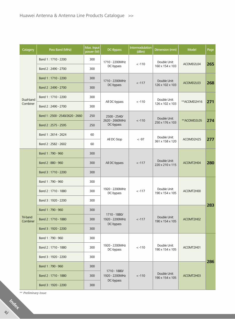
Catagery Pass Band (MHz)Max. Input power (W)
DC-BypassIntermodulation
(dBm)Dimension (mm) Model Page
Dual-band Combiner
Band 1 : 1710 - 2200 3001710 - 2200MHz
DC-bypass< -110
Double Unit: 160 x 154 x 103
ACOMD2L04 265Band 2 : 2490 - 2700 300
Band 1 : 1710 - 2200 3001710 - 2200MHz
DC-bypass< -117
Double Unit: 126 x 102 x 103
ACOMD2L03 268Band 2 : 2490 - 2700 300
Band 1 : 1710 - 2200 300
All DC-bypass < -110Double Unit:
126 x 102 x 103 **ACOMD2H16 271
Band 2 : 2490 - 2700 300
Band 1 : 2500 - 2540/2620 - 2660 250 2500 - 2540/2620 - 2660MHz
DC-bypass< -110
Double Unit: 250 x 176 x 103
**ACOMD2L05 274Band 2 : 2575 - 2595 250
Band 1 : 2614 - 2624 60
All DC-Stop < -97Double Unit:
361 x 158 x 120 ACOMD2H25 277
Band 2 : 2582 - 2602 60
Tri-band Combiner
Band 1 : 790 - 960 300
All DC-bypass < -117Double Unit:
220 x 210 x 115ACOMT2H04 280Band 2 : 880 - 960 300
Band 3 : 1710 - 2200 300
Band 1 : 790 - 960 300
1920 - 2200MHz DC-bypass
< -117Double Unit:
190 x 154 x 105 ACOMT2H00
283
Band 2 : 1710 - 1880 300
Band 3 : 1920 - 2200 300
Band 1 : 790 - 960 3001710 - 1880/
1920 - 2200MHz
DC-bypass
< -117Double Unit:
190 x 154 x 105ACOMT2H02 Band 2 : 1710 - 1880 300
Band 3 : 1920 - 2200 300
Band 1 : 790 - 960 300
1920 - 2200MHz DC-bypass
< -110Double Unit:
190 x 154 x 105 ACOMT2H01
286
Band 2 : 1710 - 1880 300
Band 3 : 1920 - 2200 300
Band 1 : 790 - 960 300 1710 - 1880/
1920 - 2200MHz
DC-bypass
< -110Double Unit:
190 x 154 x 105 ACOMT2H03 Band 2 : 1710 - 1880 300
Band 3 : 1920 - 2200 300
Huawei Antenna & Antenna Line Products Catalogue >>
xi
Index
** Preliminary Issue
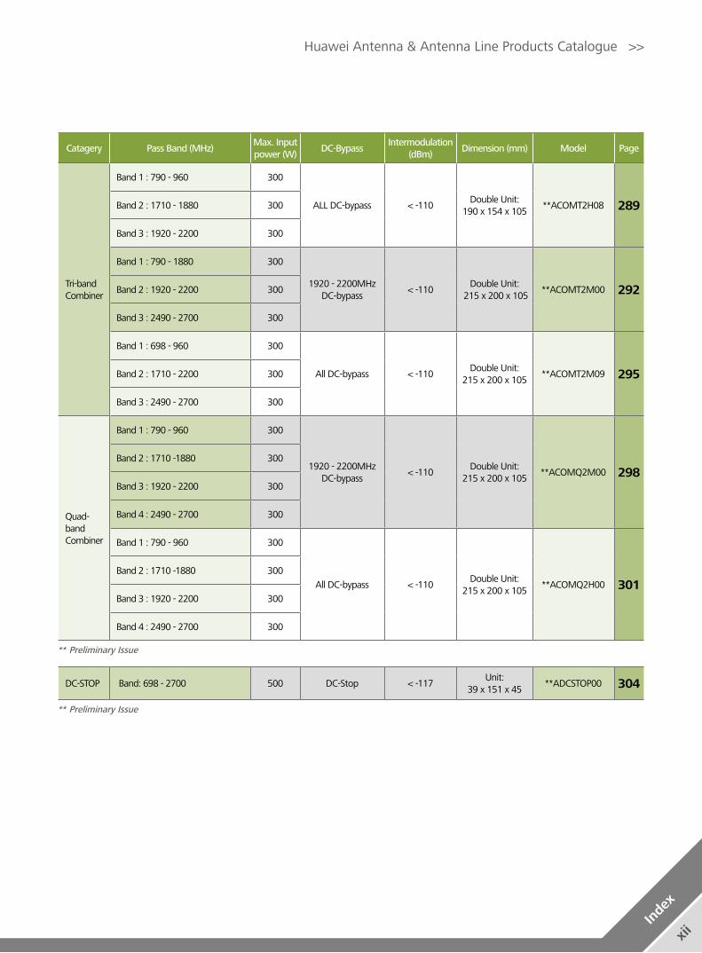
DC-STOP Band: 698 - 2700 500 DC-Stop < -117Unit:
39 x 151 x 45**ADCSTOP00 304
Huawei Antenna & Antenna Line Products Catalogue >>
xii
Inde
x
Catagery Pass Band (MHz)Max. Input power (W)
DC-BypassIntermodulation
(dBm)Dimension (mm) Model Page
Tri-band Combiner
Band 1 : 790 - 960 300
ALL DC-bypass < -110Double Unit:
190 x 154 x 105 **ACOMT2H08 289Band 2 : 1710 - 1880 300
Band 3 : 1920 - 2200 300
Band 1 : 790 - 1880 300
1920 - 2200MHz DC-bypass
< -110Double Unit:
215 x 200 x 105 **ACOMT2M00 292Band 2 : 1920 - 2200 300
Band 3 : 2490 - 2700 300
Band 1 : 698 - 960 300
All DC-bypass < -110Double Unit:
215 x 200 x 105 **ACOMT2M09 295Band 2 : 1710 - 2200 300
Band 3 : 2490 - 2700 300
Quad-band Combiner
Band 1 : 790 - 960 300
1920 - 2200MHz DC-bypass
< -110Double Unit:
215 x 200 x 105 **ACOMQ2M00 298
Band 2 : 1710 -1880 300
Band 3 : 1920 - 2200 300
Band 4 : 2490 - 2700 300
Band 1 : 790 - 960 300
All DC-bypass < -110Double Unit:
215 x 200 x 105 **ACOMQ2H00 301
Band 2 : 1710 -1880 300
Band 3 : 1920 - 2200 300
Band 4 : 2490 - 2700 300
** Preliminary Issue
** Preliminary Issue

C. Accessories for RET Systems
C - 2. Bias Tee (BT)
Frequency Range (MHz)
AISG type Insertion loss (dB) Dimension (mm) Model Page
690 - 2700 AISG v1.1AISG v2.0
≤ 0.1 (690 - 960 MHz / 1710 - 2690 MHz) ≤ 0.15 (960 - 1710 MHz)
48.5 x 151 x 45 ABT000001 310
Frequency Range (MHz)
AISG type Insertion loss (dB) Dimension (mm) Model Page
690 - 2700 AISG v1.1AISG v2.0
≤ 0.1 (690 - 960 MHz / 1710 - 2690 MHz) ≤ 0.15 (960 - 1710 MHz)
75 x 160 x 45ASBT00001(ANT Side)
313ASBT00002 (BTS Side)
C - 3. Smart Bias Tee (SBT)
Frequency Range (MHz)
AISG type Insertion loss (dB) Dimension (mm) Model Page
DC 12-15V 1.5AAISG v1.1 AISG v2.0
Interface to RCU:RS485 / Power supplyInterface to PC: USB 2.0
168 x 90 x 44 APCU00001 318
C - 5. Portable Control Unit (PCU)
C - 4. AISG Connecting Cables
AISG Connecting Cables For Remote Electrical Tilt (RET) System 316
AISG Connecting Cables For RRU RET_Port 317
C - 1. Remote Control Unit (RCU)
Input voltage range (V)
AISG typeAdjustment time (full
range) (min) Calibration time
(min) Dimension (mm) Model Page
DC 10 - 30AISG v1.1
< 2 < 4 200 x 56 x 47 ARCU01104
308AISG v2.0 ARCU02001
DC 10 - 30AISG v1.1 < 1.5
(typically, depending on antenna type)
< 3 (typically, depending
on antenna type) 180 x 65 x 54
ARCU01109 309
AISG v2.0 ARCU02004
Antenna and RCU configuration list 307
Huawei Antenna & Antenna Line Products Catalogue >>
xiii
Index

D. Mounting Instructions
D - 1. MET Installation Guide
MET Antenna with H-Brackets Installation Guide (A) 321
MET Antenna with L-Brackets Installation Guide 323
MET Antenna with H-Brackets Installation Guide (B) 325
D - 3. FET Installation Guide
FET Antenna with H-Brackets Installation Guide 333
FET Antenna with L-Brackets Installation Guide 335
D - 2. RET Installation Guide
RET Antenna with L-Brackets Installation Guide 327
RET Antenna with H-Brackets Installation Guide 330
D - 4. Tri-sector Cluster Installation Guide
Tri-sector Cluster Antenna Installation Guide 337
Huawei Antenna & Antenna Line Products Catalogue >>
xiv
Inde
x

Huawei Antenna & Antenna Line Products Catalogue >>
Huawei Network AntennasA

Electrical Properties
Frequency range (MHz) 450 - 470
Polarization Vertical
VSWR ≤1.4
Gain (dBi) 9.0
Horizontal 3dB beam width (°) 360
Vertical 3dB beam width (°) 11
Antenna pattern roundness (dB) ±1
Electrical downtilt(°) 0
Intermodulation IM3 (dBc) ≤-150
Max. CW input power (W) 150
Impedance (Ω) 50
Grounding DC Ground
OV-450-470-360-9i-0F
Model: A45VP0900
Any previous catalogue issues become invalid.
Issue: 2012-10-26
HUAWEI TECHNOLOGIES CO., LTD.
Huawei Industrial BaseBantian Longgang
Shenzhen 518129, P.R. ChinaTel: +86-755-28780808
Email: [email protected]
www.huawei.com
Copyright © Huawei Technologies Co., Ltd. 2013. All rights reserved.
THIS DOCUMENT IS FOR INFORMATION PURPOSE ONLY, AND DOSE NOT CONSTITUTE ANY KIND OF WARRANTIES.
450 - 460 MHz 455 - 465 MHz 460 - 470 MHz
Mechanical Properties
Dimensions (mm) Φ52 x 3316
Net weight (kg) 5.0
Bracket weight (kg) 2.0
Mast diameter (mm) 50 - 85
Radome material Fiberglass
Operating temperature () -55 - +65
Max. wind velocity (km/h) 200
Connector 1 x 7/16 DIN Female
1450
- 470
MHz
OV

450 - 460 MHz 455 - 465 MHz 460 - 470 MHz
Any previous catalogue issues become invalid.
Issue: 2012-10-26
HUAWEI TECHNOLOGIES CO., LTD.
Huawei Industrial BaseBantian Longgang
Shenzhen 518129, P.R. ChinaTel: +86-755-28780808
Email: [email protected]
www.huawei.com
Copyright © Huawei Technologies Co., Ltd. 2013. All rights reserved.
THIS DOCUMENT IS FOR INFORMATION PURPOSE ONLY, AND DOSE NOT CONSTITUTE ANY KIND OF WARRANTIES.
DX-450-470-65-15i-0F
Model: A45451500
Electrical Properties
Frequency range (MHz) 450 - 470
Polarization +45° , -45°
VSWR ≤1.5
Gain (dBi) 15
Horizontal 3dB beam width (°) 65
Vertical 3dB beam width (°) 16
Isolation between ports (dB) ≥ 30
Front to back ratio, copolar (dB) ≥ 25
Cross polar ratio (dB) ≥ 15
Electrical downtilt (°) 0
Intermodulation IM5 (dBc) ≤-160 (2 x 43 dBm carrier)
Max. CW input power (W) 500
Impedance (Ω) 50
Grounding DC Ground
Mechanical Properties
Dimensions (H x W x D) (mm) 2042 x 486 x 98
Net weight (kg) 28.3
Bracket weight (kg) 6.5
Mechanical downtilt (°) 0 - 16
Mast diameter (mm) 50 - 115
Radome material Fiberglass
Operating temperature () -55 - +65
Wind load (N)Frontal: 740 (v=150 km/h)Lateral: 220 (v=150 km/h)
Rear side: 1100 (v=150 km/h)
Max. wind velocity (km/h) 200
Connector 2 x 7/16 DIN Female
450 - 470X
+45°
7/16 (F) 7/16 (F)
-45°
2
450 - 470MHz
DX

806 - 866 MHz 824 - 894 MHz 880 - 960 MHz
DX-806-960-65-15i-0F
Model: A90451500
Electrical Properties
Frequency range (MHz) 806 - 866 824 - 894 880 - 960Polarization +45° , -45°
VSWR ≤1.4
Gain (dBi) 14.6 14.8 15.0Side lobe suppression for first side lobe above horizon (dB)
Typ. 17 Typ. 17 Typ. 17
Horizontal 3dB beam width (°) 67 65 62
Vertical 3dB beam width (°) 15.5 14.6 14.0Isolation between ports (dB) ≥30Front to back ratio, copolar (dB) ≥25Cross polar ratio (dB) ≥15Electrical downtilt (°) 0Intermodulation IM3 (dBc) ≤-150 (2 x 43 dBm carrier)Max. CW input power (W) 500Impedance (Ω) 50Grounding DC Ground
Mechanical Properties
Dimensions (H x W x D) (mm) 1322 x 289 x 85Net weight (kg) 9.5Bracket weight (kg) 4.6Mechanical downtilt (°) 0 - 16Mast diameter (mm) 50 - 115Radomematerial FiberglassOperating temperature () -55 .. +65
Wind load (N)Frontal: 290 (v=150 km/h)Lateral: 120 (v=150 km/h)
Rear side: 425 (v=150 km/h)Max. wind velocity (km/h) 200Connector 2 x 7/16 DIN Female
Any previous catalogue issues become invalid.
Issue: 2012-10-26
HUAWEI TECHNOLOGIES CO., LTD.
Huawei Industrial BaseBantian Longgang
Shenzhen 518129, P.R. ChinaTel: +86-755-28780808
Email: [email protected]
www.huawei.com
Copyright © Huawei Technologies Co., Ltd. 2013. All rights reserved.
THIS DOCUMENT IS FOR INFORMATION PURPOSE ONLY, AND DOSE NOT CONSTITUTE ANY KIND OF WARRANTIES.
806 - 960X
+45°
7/16 (F) 7/16 (F)
-45°
380
6 - 9
60M
Hz
DX
806 - 960X
+45°
7/16 (F) 7/16 (F)
-45°
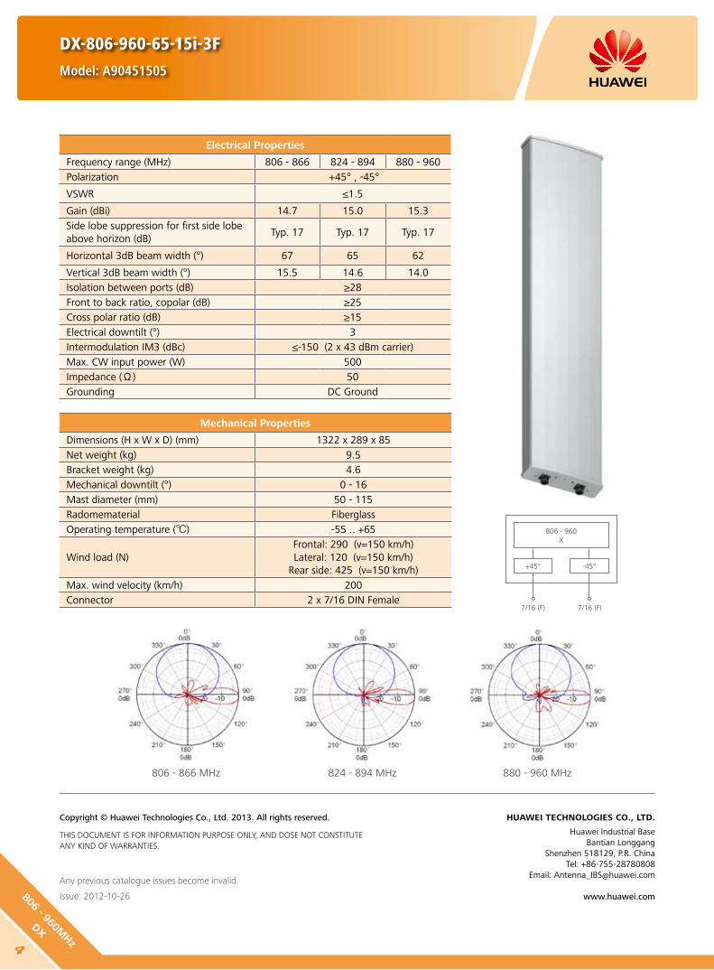
806 - 866 MHz 824 - 894 MHz 880 - 960 MHz
DX-806-960-65-15i-3F
Model: A90451505
Electrical Properties
Frequency range (MHz) 806 - 866 824 - 894 880 - 960Polarization +45° , -45°
VSWR ≤1.5
Gain (dBi) 14.7 15.0 15.3Side lobe suppression for first side lobe above horizon (dB)
Typ. 17 Typ. 17 Typ. 17
Horizontal 3dB beam width (°) 67 65 62
Vertical 3dB beam width (°) 15.5 14.6 14.0Isolation between ports (dB) ≥28Front to back ratio, copolar (dB) ≥25Cross polar ratio (dB) ≥15Electrical downtilt (°) 3Intermodulation IM3 (dBc) ≤-150 (2 x 43 dBm carrier)Max. CW input power (W) 500Impedance (Ω) 50Grounding DC Ground
Mechanical Properties
Dimensions (H x W x D) (mm) 1322 x 289 x 85Net weight (kg) 9.5Bracket weight (kg) 4.6Mechanical downtilt (°) 0 - 16Mast diameter (mm) 50 - 115Radomematerial FiberglassOperating temperature () -55 .. +65
Wind load (N)Frontal: 290 (v=150 km/h)Lateral: 120 (v=150 km/h)
Rear side: 425 (v=150 km/h)Max. wind velocity (km/h) 200Connector 2 x 7/16 DIN Female
Any previous catalogue issues become invalid.
Issue: 2012-10-26
HUAWEI TECHNOLOGIES CO., LTD.
Huawei Industrial BaseBantian Longgang
Shenzhen 518129, P.R. ChinaTel: +86-755-28780808
Email: [email protected]
www.huawei.com
Copyright © Huawei Technologies Co., Ltd. 2013. All rights reserved.
THIS DOCUMENT IS FOR INFORMATION PURPOSE ONLY, AND DOSE NOT CONSTITUTE ANY KIND OF WARRANTIES.
4
806 - 960MHz
DX

806 - 866 MHz 824 - 894 MHz 880 - 960 MHz
DX-806-960-65-15i-6F
Model: A90451501
Electrical Properties
Frequency range (MHz) 806 - 866 824 - 894 880 - 960Polarization +45° , -45°
VSWR ≤1.4
Gain (dBi) 14.5 14.7 14.9Side lobe suppression for first side lobe above horizon (dB)
Typ. 17 Typ. 17 Typ. 17
Horizontal 3dB beam width (°) 67 65 62
Vertical 3dB beam width (°) 15.5 14.9 14.0Isolation between ports (dB) ≥30Front to back ratio, copolar (dB) ≥25Cross polar ratio (dB) ≥15Electrical downtilt (°) 6Intermodulation IM3 (dBc) ≤-150 (2 x 43 dBm carrier)Max. CW input power (W) 500Impedance (Ω) 50Grounding DC Ground
Mechanical Properties
Dimensions (H x W x D) (mm) 1322 x 289 x 85Net weight (kg) 9.5Bracket weight (kg) 4.6Mechanical downtilt (°) 0 - 16Mast diameter (mm) 50 - 115Radomematerial FiberglassOperating temperature () -55 .. +65
Wind load (N)Frontal: 290 (v=150 km/h)Lateral: 120 (v=150 km/h)
Rear side: 425 (v=150 km/h)Max. wind velocity (km/h) 200Connector 2 x 7/16 DIN Female
Any previous catalogue issues become invalid.
Issue: 2012-10-26
HUAWEI TECHNOLOGIES CO., LTD.
Huawei Industrial BaseBantian Longgang
Shenzhen 518129, P.R. ChinaTel: +86-755-28780808
Email: [email protected]
www.huawei.com
Copyright © Huawei Technologies Co., Ltd. 2013. All rights reserved.
THIS DOCUMENT IS FOR INFORMATION PURPOSE ONLY, AND DOSE NOT CONSTITUTE ANY KIND OF WARRANTIES.
806 - 960X
+45°
7/16 (F) 7/16 (F)
-45°
580
6 - 9
60M
Hz
DX

806 - 960X
+45°
7/16 (F) 7/16 (F)
-45°
DX-806-960-65-15.3i-0F
Model: A90451502
Any previous catalogue issues become invalid.
Issue: 2012-10-26
HUAWEI TECHNOLOGIES CO., LTD.
Huawei Industrial BaseBantian Longgang
Shenzhen 518129, P.R. ChinaTel: +86-755-28780808
Email: [email protected]
www.huawei.com
Copyright © Huawei Technologies Co., Ltd. 2013. All rights reserved.
THIS DOCUMENT IS FOR INFORMATION PURPOSE ONLY, AND DOSE NOT CONSTITUTE ANY KIND OF WARRANTIES.
806 - 866 MHz 824 - 894 MHz 880 - 960 MHz
Electrical Properties
Frequency range (MHz) 806 - 866 824 - 894 880 - 960Polarization +45° , -45°
VSWR ≤1.4 ≤1.4 ≤1.3
Gain (dBi) 14.8 15.0 15.3Side lobe suppression for first side lobe above horizon (dB)
≥19 ≥19 ≥19
Horizontal 3dB beam width (°) 68 66 64
Vertical 3dB beam width (°) 15.9 15.4 14.3Isolation between ports (dB) ≥30Front to back ratio, copolar (dB) ≥30
Cross polar ratio (dB)0° ≥20±60° ≥10
Electrical downtilt (°) 0Intermodulation IM3 (dBc) ≤-150 (2 x 43 dBm carrier)Max. CW input power (W) 500Impedance (Ω) 50Grounding DC Ground
Mechanical Properties
Dimensions (H x W x D) (mm) 1312 x 295 x 126Net weight (kg) 10.5Bracket weight (kg) 4.6Mechanical downtilt (°) 0 - 16Mast diameter (mm) 50 - 115Radomematerial FiberglassOperating temperature () -55 .. +65
Wind load (N)Frontal: 290 (v=150 km/h)Lateral: 180 (v=150 km/h)
Rear side: 430 (v=150 km/h)Max. wind velocity (km/h) 200Connector 2 x 7/16 DIN Female
6
806 - 960MHz
DX

806 - 960X
+45°
7/16 (F) 7/16 (F)
-45°
806 - 866 MHz 824 - 894 MHz 880 - 960 MHz
DX-806-960-65-15.3i-6F
Model: A90451503
Electrical Properties
Frequency range (MHz) 806 - 866 824 - 894 880 - 960Polarization +45° , -45°
VSWR ≤1.35 ≤1.35 ≤1.3
Gain (dBi) 14.7 14.9 15.2Side lobe suppression for first side lobe above horizon (dB)
≥19 ≥19 ≥19
Horizontal 3dB beam width (°) 68 66 64
Vertical 3dB beam width (°) 15.9 15.4 14.3Isolation between ports (dB) ≥30Front to back ratio, copolar (dB) ≥30
Cross polar ratio (dB)0° ≥20±60° ≥10
Electrical downtilt (°) 6Intermodulation IM3 (dBc) ≤-150 (2 x 43 dBm carrier)Max. CW input power (W) 500Impedance (Ω) 50Grounding DC Ground
Any previous catalogue issues become invalid.
Issue: 2012-10-26
HUAWEI TECHNOLOGIES CO., LTD.
Huawei Industrial BaseBantian Longgang
Shenzhen 518129, P.R. ChinaTel: +86-755-28780808
Email: [email protected]
www.huawei.com
Copyright © Huawei Technologies Co., Ltd. 2013. All rights reserved.
THIS DOCUMENT IS FOR INFORMATION PURPOSE ONLY, AND DOSE NOT CONSTITUTE ANY KIND OF WARRANTIES.
Mechanical Properties
Dimensions (H x W x D) (mm) 1312 x 295 x 126Net weight (kg) 10.5Bracket weight (kg) 4.6Mechanical downtilt (°) 0 - 16Mast diameter (mm) 50 - 115Radomematerial FiberglassOperating temperature () -55 .. +65
Wind load (N)Frontal: 290 (v=150 km/h)Lateral: 180 (v=150 km/h)
Rear side: 430 (v=150 km/h)Max. wind velocity (km/h) 200Connector 2 x 7/16 DIN Female
780
6 - 9
60M
Hz
DX

806 - 960X
+45°
7/16 (F) 7/16 (F)
-45°
Electrical Properties
Frequency range (MHz) 806 - 866 824 - 894 880 - 960Polarization +45° , -45°
VSWR ≤1.37
Gain (dBi) 16.6 16.8 17.0Side lobe suppression for first side lobe above horizon (dB)
Typ. 17 Typ. 17 Typ. 17
Horizontal 3dB beam width (°) 67 64 63
Vertical 3dB beam width (°) 11.0 10.5 10.0Isolation between ports (dB) ≥28Front to back ratio, copolar (dB) ≥25Cross polar ratio (dB) ≥15Electrical downtilt (°) 0Intermodulation IM3 (dBc) ≤-150 (2 x 43 dBm carrier)Max. CW input power (W) 500Impedance (Ω) 50Grounding DC Ground
Mechanical Properties
Dimensions (H x W x D) (mm) 1932 x 289 x 85Net weight (kg) 13.5Bracket weight (kg) 4.6Mechanical downtilt (°) 0 - 12Mast diameter (mm) 50 - 115Radomematerial FiberglassOperating temperature () -55 .. +65
Wind load (N)Frontal: 420 (v=150 km/h)Lateral: 175 (v=150 km/h)
Rear side: 620 (v=150 km/h)Max. wind velocity (km/h) 200Connector 2 x 7/16 DIN Female
806 - 866 MHz 824 - 894 MHz 880 - 960 MHz
DX-806-960-65-17i-0F
Model: A90451700
Any previous catalogue issues become invalid.
Issue: 2012-10-26
HUAWEI TECHNOLOGIES CO., LTD.
Huawei Industrial BaseBantian Longgang
Shenzhen 518129, P.R. ChinaTel: +86-755-28780808
Email: [email protected]
www.huawei.com
Copyright © Huawei Technologies Co., Ltd. 2013. All rights reserved.
THIS DOCUMENT IS FOR INFORMATION PURPOSE ONLY, AND DOSE NOT CONSTITUTE ANY KIND OF WARRANTIES.
8
806 - 960MHz
DX

DX-806-960-65-17i-3F
Model: A90451705
Electrical Properties
Frequency range (MHz) 806 - 866 824 - 894 880 - 960Polarization +45° , -45°
VSWR ≤1.5
Gain (dBi) 16.7 17.0 17.2Side lobe suppression for first side lobe above horizon (dB)
Typ. 17 Typ. 17 Typ. 17
Horizontal 3dB beam width (°) 67 64 63
Vertical 3dB beam width (°) 11.0 10.5 10.0Isolation between ports (dB) ≥28Front to back ratio, copolar (dB) ≥25Cross polar ratio (dB) ≥15Electrical downtilt (°) 3Intermodulation IM3 (dBc) ≤-150 (2 x 43 dBm carrier)Max. CW input power (W) 500Impedance (Ω) 50Grounding DC Ground
Mechanical Properties
Dimensions (H x W x D) (mm) 1932 x 289 x 85Net weight (kg) 13.5Bracket weight (kg) 4.6Mechanical downtilt (°) 0 - 12Mast diameter (mm) 50 - 115Radomematerial FiberglassOperating temperature () -55 .. +65
Wind load (N)Frontal: 420 (v=150 km/h)Lateral: 175 (v=150 km/h)
Rear side: 620 (v=150 km/h)Max. wind velocity (km/h) 200Connector 2 x 7/16 DIN Female
Any previous catalogue issues become invalid.
Issue: 2012-10-26
HUAWEI TECHNOLOGIES CO., LTD.
Huawei Industrial BaseBantian Longgang
Shenzhen 518129, P.R. ChinaTel: +86-755-28780808
Email: [email protected]
www.huawei.com
Copyright © Huawei Technologies Co., Ltd. 2013. All rights reserved.
THIS DOCUMENT IS FOR INFORMATION PURPOSE ONLY, AND DOSE NOT CONSTITUTE ANY KIND OF WARRANTIES.
806 - 866 MHz 824 - 894 MHz 880 - 960 MHz
806 - 960X
+45°
7/16 (F) 7/16 (F)
-45°
980
6 - 9
60M
Hz
DX

DX-806-960-65-18i-0F
Model: A90451800
Electrical Properties
Frequency range (MHz) 806 - 866 824 - 894 880 - 960Polarization +45° , -45°
VSWR ≤1.45
Gain (dBi) 17.4 17.6 17.8Side lobe suppression for first side lobe above horizon (dB)
Typ. 17 Typ. 17 Typ. 17
Horizontal 3dB beam width (°) 67 64 63
Vertical 3dB beam width (°) 8.2 7.5 7.0Isolation between ports (dB) ≥28Front to back ratio, copolar (dB) ≥25Cross polar ratio (dB) ≥15Electrical downtilt (°) 0Intermodulation IM3 (dBc) ≤-150 (2 x 43 dBm carrier)Max. CW input power (W) 500Impedance (Ω) 50Grounding DC Ground
Mechanical Properties
Dimensions (H x W x D) (mm) 2572 x 289 x 85Net weight (kg) 16.5Bracket weight (kg) 4.6Mechanical downtilt (°) 0 - 8Mast diameter (mm) 50 - 115Radomematerial FiberglassOperating temperature () -55 .. +65
Wind load (N)Frontal: 560 (v=150 km/h)Lateral: 235 (v=150 km/h)
Rear side: 830 (v=150 km/h)Max. wind velocity (km/h) 200Connector 2 x 7/16 DIN Female
806 - 866 MHz 824 - 894 MHz 880 - 960 MHz
Any previous catalogue issues become invalid.
Issue: 2012-10-26
HUAWEI TECHNOLOGIES CO., LTD.
Huawei Industrial BaseBantian Longgang
Shenzhen 518129, P.R. ChinaTel: +86-755-28780808
Email: [email protected]
www.huawei.com
Copyright © Huawei Technologies Co., Ltd. 2013. All rights reserved.
THIS DOCUMENT IS FOR INFORMATION PURPOSE ONLY, AND DOSE NOT CONSTITUTE ANY KIND OF WARRANTIES.
806 - 960X
+45°
7/16 (F) 7/16 (F)
-45°
10
806 - 960MHz
DX

DX-806-960-65-18i-3F
Model: A90451805
806 - 866 MHz 824 - 894 MHz 880 - 960 MHz
Electrical Properties
Frequency range (MHz) 806 - 866 824 - 894 880 - 960
Polarization +45° , -45°
VSWR ≤ 1.45
Gain (dBi) 17.8 18.0 18.2
Side lobe suppression for first side lobe above horizon (dB)
Typ. 17 Typ. 17 Typ. 17
Horizontal 3dB beam width (°) 67 64 63
Vertical 3dB beam width (°) 8.2 7.5 7.0
Isolation between ports (dB) ≥ 28
Front to back ratio, copolar (dB) ≥25
Cross polar ratio (dB) ≥15
Electrical downtilt (°) 3
Intermodulation IM3 (dBc) ≤ -150 (2 x 43 dBm carrier)
Max. CW input power (W) 500
Impedance (Ω) 50
Grounding DC Ground
Any previous catalogue issues become invalid.
Issue: 2012-10-26
HUAWEI TECHNOLOGIES CO., LTD.
Huawei Industrial BaseBantian Longgang
Shenzhen 518129, P.R. ChinaTel: +86-755-28780808
Email: [email protected]
www.huawei.com
Copyright © Huawei Technologies Co., Ltd. 2013. All rights reserved.
THIS DOCUMENT IS FOR INFORMATION PURPOSE ONLY, AND DOSE NOT CONSTITUTE ANY KIND OF WARRANTIES.
Mechanical Properties
Dimensions (H x W x D) (mm) 2572 x 289 x 85
Net weight (kg) 16.5
Bracket weight (kg) 4.6
Mechanical downtilt (°) 0 - 8
Mast diameter (mm) 50 - 115
Radomematerial Fiberglass
Operating temperature () -55 .. +65
Wind load (N)Frontal: 560 (v=150 km/h)Lateral: 235 (v=150 km/h)
Rear side: 830 (v=150 km/h)
Max. wind velocity (km/h) 200
Connector 2 x 7/16 DIN Female
806 - 960X
+45°
7/16 (F) 7/16 (F)
-45°
1180
6 - 9
60M
Hz
DX
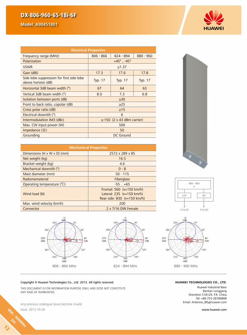
806 - 866 MHz 824 - 894 MHz 880 - 960 MHz
DX-806-960-65-18i-6F
Model: A90451801
Electrical Properties
Frequency range (MHz) 806 - 866 824 - 894 880 - 960Polarization +45° , -45°
VSWR ≤1.37
Gain (dBi) 17.3 17.6 17.8Side lobe suppression for first side lobe above horizon (dB)
Typ. 17 Typ. 17 Typ. 17
Horizontal 3dB beam width (°) 67 64 63
Vertical 3dB beam width (°) 8.0 7.3 6.8Isolation between ports (dB) ≥30Front to back ratio, copolar (dB) ≥25Cross polar ratio (dB) ≥15Electrical downtilt (°) 6Intermodulation IM3 (dBc) ≤-150 (2 x 43 dBm carrier)Max. CW input power (W) 500Impedance (Ω) 50Grounding DC Ground
Any previous catalogue issues become invalid.
Issue: 2012-10-26
HUAWEI TECHNOLOGIES CO., LTD.
Huawei Industrial BaseBantian Longgang
Shenzhen 518129, P.R. ChinaTel: +86-755-28780808
Email: [email protected]
www.huawei.com
Copyright © Huawei Technologies Co., Ltd. 2013. All rights reserved.
THIS DOCUMENT IS FOR INFORMATION PURPOSE ONLY, AND DOSE NOT CONSTITUTE ANY KIND OF WARRANTIES.
Mechanical Properties
Dimensions (H x W x D) (mm) 2572 x 289 x 85Net weight (kg) 16.5Bracket weight (kg) 4.6Mechanical downtilt (°) 0 - 8Mast diameter (mm) 50 - 115Radomematerial FiberglassOperating temperature () -55 .. +65
Wind load (N)Frontal: 560 (v=150 km/h)Lateral: 235 (v=150 km/h)
Rear side: 830 (v=150 km/h)Max. wind velocity (km/h) 200Connector 2 x 7/16 DIN Female
806 - 960X
+45°
7/16 (F) 7/16 (F)
-45°
12
806 - 960MHz
DX
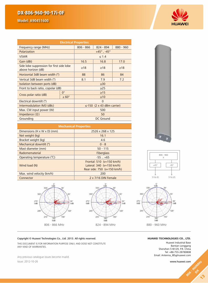
806 - 866 MHz 824 - 894 MHz 880 - 960 MHz
DX-806-960-90-17i-0F
Model: A90451600
Electrical Properties
Frequency range (MHz) 806 - 866 824 - 894 880 - 960Polarization +45° , -45°
VSWR ≤ 1.4
Gain (dBi) 16.5 16.8 17.0Side lobe suppression for first side lobe above horizon (dB)
≥18 ≥18 ≥18
Horizontal 3dB beam width (°) 88 86 84
Vertical 3dB beam width (°) 8.1 7.9 7.2Isolation between ports (dB) ≥30Front to back ratio, copolar (dB) ≥25
Cross polar ratio (dB)0° ≥15±60° ≥10
Electrical downtilt (°) 0Intermodulation IM3 (dBc) ≤-150 (2 x 43 dBm carrier)Max. CW input power (W) 500Impedance (Ω) 50Grounding DC Ground
Any previous catalogue issues become invalid.
Issue: 2012-10-26
HUAWEI TECHNOLOGIES CO., LTD.
Huawei Industrial BaseBantian Longgang
Shenzhen 518129, P.R. ChinaTel: +86-755-28780808
Email: [email protected]
www.huawei.com
Copyright © Huawei Technologies Co., Ltd. 2013. All rights reserved.
THIS DOCUMENT IS FOR INFORMATION PURPOSE ONLY, AND DOSE NOT CONSTITUTE ANY KIND OF WARRANTIES.
Mechanical Properties
Dimensions (H x W x D) (mm) 2526 x 268 x 125Net weight (kg) 16.1Bracket weight (kg) 4.6Mechanical downtilt (°) 0 - 8Mast diameter (mm) 50 - 115Radomematerial FiberglassOperating temperature () -55 .. +65
Wind load (N)Frontal: 510 (v=150 km/h)Lateral: 340 (v=150 km/h)
Rear side: 750 (v=150 km/h)Max. wind velocity (km/h) 200Connector 2 x 7/16 DIN Female
806 - 960X
+45°
7/16 (F) 7/16 (F)
-45°
1380
6 - 9
60M
Hz
DX
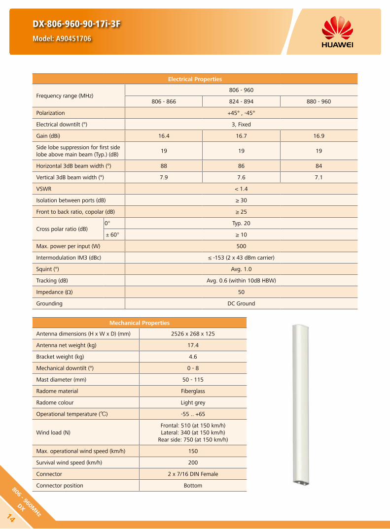
DX-806-960-90-17i-3F
Model: A90451706
Electrical Properties
Frequency range (MHz)806 - 960
806 - 866 824 - 894 880 - 960
Polarization +45° , -45°
Electrical downtilt (°) 3, Fixed
Gain (dBi) 16.4 16.7 16.9
Side lobe suppression for first side lobe above main beam (Typ.) (dB)
19 19 19
Horizontal 3dB beam width (°) 88 86 84
Vertical 3dB beam width (°) 7.9 7.6 7.1
VSWR < 1.4
Isolation between ports (dB) ≥ 30
Front to back ratio, copolar (dB) ≥ 25
Cross polar ratio (dB)0° Typ. 20
±60° ≥ 10
Max. power per input (W) 500
Intermodulation IM3 (dBc) ≤ -153 (2 x 43 dBm carrier)
Squint (°) Avg. 1.0
Tracking (dB) Avg. 0.6 (within 10dB HBW)
Impedance (Ω) 50
Grounding DC Ground
Mechanical Properties
Antenna dimensions (H x W x D) (mm) 2526 x 268 x 125
Antenna net weight (kg) 17.4
Bracket weight (kg) 4.6
Mechanical downtilt (°) 0 - 8
Mast diameter (mm) 50 - 115
Radome material Fiberglass
Radome colour Light grey
Operational temperature () -55 .. +65
Wind load (N)Frontal: 510 (at 150 km/h)Lateral: 340 (at 150 km/h)
Rear side: 750 (at 150 km/h)
Max. operational wind speed (km/h) 150
Survival wind speed (km/h) 200
Connector 2 x 7/16 DIN Female
Connector position Bottom
14
806 - 960MHz
DX

DX-806-960-90-17i-3F
Model: A90451706
Unit: mm
806 - 960X
+45°
7/16 (F) 7/16 (F)
-45°
120
806 - 960 MHz
HINT
Extraordinary operating conditions, such as heavy icing or storm wind, may result in the breakage of an antenna. These facts must be considered during the site planning process.
The installation team must be properly qualified and also be familiar with the relevant national safety regulations.
Any previous catalogue issues become invalid.
Issue: 2012-10-26
HUAWEI TECHNOLOGIES CO., LTD.
Huawei Industrial BaseBantian Longgang
Shenzhen 518129, P.R. ChinaTel: +86-755-28780808
Email: [email protected]
www.huawei.com
Copyright © Huawei Technologies Co., Ltd. 2013. All rights reserved.
THIS DOCUMENT IS FOR INFORMATION PURPOSE ONLY, AND DOSE NOT CONSTITUTE ANY KIND OF WARRANTIES.
1580
6 - 9
60M
Hz
DX
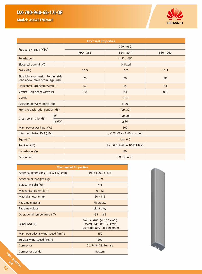
DX-790-960-65-17i-0F
Model: A90451702v01
Electrical Properties
Frequency range (MHz)790 - 960
790 - 862 824 - 894 880 - 960
Polarization +45° , -45°
Electrical downtilt (°) 0, Fixed
Gain (dBi) 16.5 16.7 17.1
Side lobe suppression for first side lobe above main beam (Typ.) (dB)
20 20 20
Horizontal 3dB beam width (°) 67 65 63
Vertical 3dB beam width (°) 9.8 9.4 8.9
VSWR < 1.4
Isolation between ports (dB) ≥ 30
Front to back ratio, copolar (dB) Typ. 32
Cross polar ratio (dB)0° Typ. 25
±60° ≥ 10
Max. power per input (W) 500
Intermodulation IM3 (dBc) ≤ -153 (2 x 43 dBm carrier)
Squint (°) Avg. 0.6
Tracking (dB) Avg. 0.6 (within 10dB HBW)
Impedance (Ω) 50
Grounding DC Ground
Mechanical Properties
Antenna dimensions (H x W x D) (mm) 1936 x 260 x 135
Antenna net weight (kg) 12.9
Bracket weight (kg) 4.6
Mechanical downtilt (°) 0 - 12
Mast diameter (mm) 50 - 115
Radome material Fiberglass
Radome colour Light grey
Operational temperature () -55 .. +65
Wind load (N)Frontal: 665 (at 150 km/h) Lateral: 345 (at 150 km/h)
Rear side: 880 (at 150 km/h)
Max. operational wind speed (km/h) 150
Survival wind speed (km/h) 200
Connector 2 x 7/16 DIN Female
Connector position Bottom
16
790 - 960MHz
DX

790 - 960 MHz
790 - 960X
+45°
7/16 (F) 7/16 (F)
-45°
DX-790-960-65-17i-0F
Model: A90451702v01
Unit: mm70
HINT
Extraordinary operating conditions, such as heavy icing or storm wind, may result in the breakage of an antenna. These facts must be considered during the site planning process.
The installation team must be properly qualified and also be familiar with the relevant national safety regulations.
Any previous catalogue issues become invalid.
Issue: 2012-10-26
HUAWEI TECHNOLOGIES CO., LTD.
Huawei Industrial BaseBantian Longgang
Shenzhen 518129, P.R. ChinaTel: +86-755-28780808
Email: [email protected]
www.huawei.com
Copyright © Huawei Technologies Co., Ltd. 2013. All rights reserved.
THIS DOCUMENT IS FOR INFORMATION PURPOSE ONLY, AND DOSE NOT CONSTITUTE ANY KIND OF WARRANTIES.
1779
0 - 9
60M
Hz
DX

DX-790-960-65-17i-3F
Model: A90451705v01
Electrical Properties
Frequency range (MHz)790 - 960
790 - 862 824 - 894 880 - 960
Polarization +45° , -45°
Electrical downtilt (°) 3, Fixed
Gain (dBi) 16.5 16.7 17.1
Side lobe suppression for first side lobe above main beam (Typ.) (dB)
19 19 19
Horizontal 3dB beam width (°) 67 65 63
Vertical 3dB beam width (°) 9.8 9.4 8.9
VSWR < 1.4
Isolation between ports (dB) ≥ 30
Front to back ratio, copolar (dB) Typ. 32
Cross polar ratio (dB)0° Typ. 25
±60° ≥ 10
Max. power per input (W) 500
Intermodulation IM3 (dBc) ≤ -153 (2 x 43 dBm carrier)
Squint (°) Avg. 0.6
Tracking (dB) Avg. 0.6 (within 10dB HBW)
Impedance (Ω) 50
Grounding DC Ground
Mechanical Properties
Antenna dimensions (H x W x D) (mm) 1936 x 260 x 135
Antenna net weight (kg) 12.9
Bracket weight (kg) 4.6
Mechanical downtilt (°) 0 - 12
Mast diameter (mm) 50 - 115
Radome material Fiberglass
Radome colour Light grey
Operational temperature () -55 .. +65
Wind load (N)Frontal: 665 (at 150 km/h) Lateral: 345 (at 150 km/h)
Rear side: 880 (at 150 km/h)
Max. operational wind speed (km/h) 150
Survival wind speed (km/h) 200
Connector 2 x 7/16 DIN Female
Connector position Bottom
18
790 - 960MHz
DX

DX-790-960-65-17i-3F
Model: A90451705v01
790 - 960 MHz
790 - 960X
+45°
7/16 (F) 7/16 (F)
-45°
Unit: mm70
HINT
Extraordinary operating conditions, such as heavy icing or storm wind, may result in the breakage of an antenna. These facts must be considered during the site planning process.
The installation team must be properly qualified and also be familiar with the relevant national safety regulations.
Any previous catalogue issues become invalid.
Issue: 2012-10-26
HUAWEI TECHNOLOGIES CO., LTD.
Huawei Industrial BaseBantian Longgang
Shenzhen 518129, P.R. ChinaTel: +86-755-28780808
Email: [email protected]
www.huawei.com
Copyright © Huawei Technologies Co., Ltd. 2013. All rights reserved.
THIS DOCUMENT IS FOR INFORMATION PURPOSE ONLY, AND DOSE NOT CONSTITUTE ANY KIND OF WARRANTIES.
1979
0 - 9
60M
Hz
DX

DX-790-960-65-17i-6F
Model: A90451709
Electrical Properties
Frequency range (MHz)790 - 960
790 - 862 824 - 894 880 - 960
Polarization +45° , -45°
Electrical downtilt (°) 6, Fixed
Gain (dBi) 16.5 16.7 17.1
Side lobe suppression for first side lobe above main beam (Typ.) (dB)
19 19 18
Horizontal 3dB beam width (°) 67 65 63
Vertical 3dB beam width (°) 9.8 9.4 8.9
VSWR < 1.4
Isolation between ports (dB) ≥ 30
Front to back ratio, copolar (dB) Typ. 30
Cross polar ratio (dB)0° Typ. 25
±60° ≥ 10
Max. power per input (W) 500
Intermodulation IM3 (dBc) ≤ -153 (2 x 43 dBm carrier)
Max. power per input (W) Avg. 0.6
Intermodulation IM3 (dBc) Avg. 0.8 (within 10dB HBW)
Impedance (Ω) 50
Grounding DC Ground
Mechanical Properties
Antenna dimensions (H x W x D) (mm) 1936 x 260 x 135
Antenna net weight (kg) 12.9
Bracket weight (kg) 4.6
Mechanical downtilt (°) 0 - 12
Mast diameter (mm) 50 - 115
Radome material Fiberglass
Radome colour Light grey
Operational temperature () -55 .. +65
Wind load (N)Frontal: 665 (at 150 km/h) Lateral: 345 (at 150 km/h)
Rear side: 880 (at 150 km/h)
Max. operational wind speed (km/h) 150
Survival wind speed (km/h) 200
Connector 2 x 7/16 DIN Female
Connector position Bottom
20
790 - 960MHz
DX

DX-790-960-65-17i-6F
Model: A90451709
790 - 960 MHz
Unit: mm70
HINT
Extraordinary operating conditions, such as heavy icing or storm wind, may result in the breakage of an antenna. These facts must be considered during the site planning process.
The installation team must be properly qualified and also be familiar with the relevant national safety regulations.
Any previous catalogue issues become invalid.
Issue: 2012-10-26
HUAWEI TECHNOLOGIES CO., LTD.
Huawei Industrial BaseBantian Longgang
Shenzhen 518129, P.R. ChinaTel: +86-755-28780808
Email: [email protected]
www.huawei.com
Copyright © Huawei Technologies Co., Ltd. 2013. All rights reserved.
THIS DOCUMENT IS FOR INFORMATION PURPOSE ONLY, AND DOSE NOT CONSTITUTE ANY KIND OF WARRANTIES.
790 - 960X
+45°
7/16 (F) 7/16 (F)
-45°
2179
0 - 9
60M
Hz
DX

DX-790-960-65-18i-0F
Model: A90451802v01
Electrical Properties
Frequency range (MHz)790 - 960
790 - 862 824 - 894 880 - 960
Polarization +45° , -45°
Electrical downtilt (°) 0, Fixed
Gain (dBi) 17.5 17.7 18.0
Side lobe suppression for first side lobe above main beam (Typ.) (dB)
21 21 21
Horizontal 3dB beam width (°) 67 65 63
Vertical 3dB beam width (°) 7.8 7.5 7.1
VSWR < 1.4
Isolation between ports (dB) ≥ 30
Front to back ratio, copolar (dB) Typ. 32
Cross polar ratio (dB)0° Typ. 25
±60° ≥ 10
Max. power per input (W) 500
Intermodulation IM3 (dBc) ≤ -153 (2 x 43 dBm carrier)
Squint (°) Avg. 0.5
Tracking (dB) Avg. 0.5 (within 10dB HBW)
Impedance (Ω) 50
Grounding DC Ground
Mechanical Properties
Antenna dimensions (H x W x D) (mm) 2535 x 259 x 135
Antenna net weight (kg) 16.3
Bracket weight (kg) 5.6
Mechanical downtilt (°) 0 - 8
Mast diameter (mm) 50 - 115
Radome material Fiberglass
Radome colour Light grey
Operational temperature () -55 .. +65
Wind load (N)Frontal: 910 (at 150 km/h)Lateral: 470 (at 150 km/h)
Rear side: 1200 (at 150 km/h)
Max. operational wind speed (km/h) 150
Survival wind speed (km/h) 200
Connector 2 x 7/16 DIN Female
Connector position Bottom
22
790 - 960MHz
DX

DX-790-960-65-18i-0F
Model: A90451802v01
790 - 960 MHz
Unit: mm70
HINT
Extraordinary operating conditions, such as heavy icing or storm wind, may result in the breakage of an antenna. These facts must be considered during the site planning process.
The installation team must be properly qualified and also be familiar with the relevant national safety regulations.
Any previous catalogue issues become invalid.
Issue: 2012-10-26
HUAWEI TECHNOLOGIES CO., LTD.
Huawei Industrial BaseBantian Longgang
Shenzhen 518129, P.R. ChinaTel: +86-755-28780808
Email: [email protected]
www.huawei.com
Copyright © Huawei Technologies Co., Ltd. 2013. All rights reserved.
THIS DOCUMENT IS FOR INFORMATION PURPOSE ONLY, AND DOSE NOT CONSTITUTE ANY KIND OF WARRANTIES.
790 - 960X
+45°
7/16 (F) 7/16 (F)
-45°
2379
0 - 9
60M
Hz
DX

DX-790-960-65-18i-3F
Model: A90451805v01
Electrical Properties
Frequency range (MHz)790 - 960
790 - 862 824 - 894 880 - 960
Polarization +45° , -45°
Electrical downtilt (°) 3, Fixed
Gain (dBi) 17.5 17.7 18.0
Side lobe suppression for first side lobe above main beam (Typ.) (dB)
20 20 20
Horizontal 3dB beam width (°) 67 65 63
Vertical 3dB beam width (°) 7.8 7.5 7.1
VSWR < 1.4
Isolation between ports (dB) ≥ 30
Front to back ratio, copolar (dB) Typ. 32
Cross polar ratio (dB)0° Typ. 25
±60° ≥ 10
Max. power per input (W) 500
Intermodulation IM3 (dBc) ≤ -153 (2 x 43 dBm carrier)
Squint (°) Avg. 0.5
Tracking (dB) Avg. 0.5 (within 10dB HBW)
Impedance (Ω) 50
Grounding DC Ground
Mechanical Properties
Antenna dimensions (H x W x D) (mm) 2535 x 259 x 135
Antenna net weight (kg) 16.3
Bracket weight (kg) 5.6
Mechanical downtilt (°) 0 - 8
Mast diameter (mm) 50 - 115
Radome material Fiberglass
Radome colour Light grey
Operational temperature () -55 .. +65
Wind load (N)Frontal: 910 (at 150 km/h)Lateral: 470 (at 150 km/h)
Rear side: 1200 (at 150 km/h)
Max. operational wind speed (km/h) 150
Survival wind speed (km/h) 200
Connector 2 x 7/16 DIN Female
Connector position Bottom
24
790 - 960MHz
DX

DX-790-960-65-18i-3F
Model: A90451805v01
790 - 960 MHz
790 - 960X
+45°
7/16 (F) 7/16 (F)
-45°
Unit: mm70
HINT
Extraordinary operating conditions, such as heavy icing or storm wind, may result in the breakage of an antenna. These facts must be considered during the site planning process.
The installation team must be properly qualified and also be familiar with the relevant national safety regulations.
Any previous catalogue issues become invalid.
Issue: 2012-10-26
HUAWEI TECHNOLOGIES CO., LTD.
Huawei Industrial BaseBantian Longgang
Shenzhen 518129, P.R. ChinaTel: +86-755-28780808
Email: [email protected]
www.huawei.com
Copyright © Huawei Technologies Co., Ltd. 2013. All rights reserved.
THIS DOCUMENT IS FOR INFORMATION PURPOSE ONLY, AND DOSE NOT CONSTITUTE ANY KIND OF WARRANTIES.
2579
0 - 9
60M
Hz
DX

DX-1710-2170-90-17i-0F
Model: A19451704
Electrical Properties
Frequency range (MHz)1710 - 2170
1710 - 1880 1850 - 1990 1920 - 2170
Polarization +45° , -45°
Electrical downtilt (°) 0, Fixed
Gain (dBi) 16.5 16.7 17.1
Side lobe suppression for first side lobe above horizon (dB)
18 20 20
Horizontal 3dB beam width (°) 86 85 84
Vertical 3dB beam width (°) 7.0 6.7 6.4
VSWR < 1.4
Isolation between ports (dB) ≥ 30
Front to back ratio, copolar (dB) ≥ 25
Cross polar ratio (dB)0° Typ. 20
±60° ≥ 10
Max. power per input (W) 300 (at 50 ambient temperature)
Intermodulation IM3 (dBc) ≤ -153 (2 x 43 dBm carrier)
Squint (°) Avg. 2.0
Tracking (dB) Avg. 0.8 (within 10dB HBW)
Impedance (Ω) 50
Grounding DC Ground
Mechanical Properties
Antenna dimensions (H x W x D) (mm) 1306 x 155 x 79
Antenna net weight (kg) 5.4
Bracket weight (kg) 3.0
Mechanical downtilt (°) 0 - 16
Mast diameter (mm) 50 - 115
Radome material Fiberglass
Radome colour Light grey
Operational temperature () -55 .. +65
Wind load (N)Frontal: 290 (at 150 km/h)Lateral: 115 (at 150 km/h)
Rear side: 335 (at 150 km/h)
Max. operational wind speed (km/h) 150
Survival wind speed (km/h) 200
Connector 2 x 7/16 DIN Female
Connector position Bottom
26
1710 - 2170MHz
DX

DX-1710-2170-90-17i-0F
Model: A19451704
Unit: mm
1710 - 2170X
+45°
7/16 (F) 7/16 (F)
-45°
80
1710 - 2170 MHz
HINT
Extraordinary operating conditions, such as heavy icing or storm wind, may result in the breakage of an antenna. These facts must be considered during the site planning process.
The installation team must be properly qualified and also be familiar with the relevant national safety regulations.
Any previous catalogue issues become invalid.
Issue: 2012-10-26
HUAWEI TECHNOLOGIES CO., LTD.
Huawei Industrial BaseBantian Longgang
Shenzhen 518129, P.R. ChinaTel: +86-755-28780808
Email: [email protected]
www.huawei.com
Copyright © Huawei Technologies Co., Ltd. 2013. All rights reserved.
THIS DOCUMENT IS FOR INFORMATION PURPOSE ONLY, AND DOSE NOT CONSTITUTE ANY KIND OF WARRANTIES.
271710
- 21
70M
Hz
DX
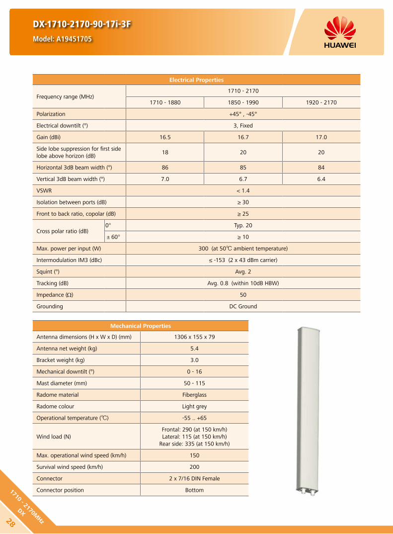
DX-1710-2170-90-17i-3F
Model: A19451705
Electrical Properties
Frequency range (MHz)1710 - 2170
1710 - 1880 1850 - 1990 1920 - 2170
Polarization +45° , -45°
Electrical downtilt (°) 3, Fixed
Gain (dBi) 16.5 16.7 17.0
Side lobe suppression for first side lobe above horizon (dB)
18 20 20
Horizontal 3dB beam width (°) 86 85 84
Vertical 3dB beam width (°) 7.0 6.7 6.4
VSWR < 1.4
Isolation between ports (dB) ≥ 30
Front to back ratio, copolar (dB) ≥ 25
Cross polar ratio (dB)0° Typ. 20
±60° ≥ 10
Max. power per input (W) 300 (at 50 ambient temperature)
Intermodulation IM3 (dBc) ≤ -153 (2 x 43 dBm carrier)
Squint (°) Avg. 2
Tracking (dB) Avg. 0.8 (within 10dB HBW)
Impedance (Ω) 50
Grounding DC Ground
Mechanical Properties
Antenna dimensions (H x W x D) (mm) 1306 x 155 x 79
Antenna net weight (kg) 5.4
Bracket weight (kg) 3.0
Mechanical downtilt (°) 0 - 16
Mast diameter (mm) 50 - 115
Radome material Fiberglass
Radome colour Light grey
Operational temperature () -55 .. +65
Wind load (N)Frontal: 290 (at 150 km/h)Lateral: 115 (at 150 km/h)
Rear side: 335 (at 150 km/h)
Max. operational wind speed (km/h) 150
Survival wind speed (km/h) 200
Connector 2 x 7/16 DIN Female
Connector position Bottom
28
1710 - 2170MHz
DX

DX-1710-2170-90-17i-3F
Model: A19451705
Unit: mm
1710 - 2170X
+45°
7/16 (F) 7/16 (F)
-45°
80
1710 - 2170 MHz
HINT
Extraordinary operating conditions, such as heavy icing or storm wind, may result in the breakage of an antenna. These facts must be considered during the site planning process.
The installation team must be properly qualified and also be familiar with the relevant national safety regulations.
Any previous catalogue issues become invalid.
Issue: 2012-10-26
HUAWEI TECHNOLOGIES CO., LTD.
Huawei Industrial BaseBantian Longgang
Shenzhen 518129, P.R. ChinaTel: +86-755-28780808
Email: [email protected]
www.huawei.com
Copyright © Huawei Technologies Co., Ltd. 2013. All rights reserved.
THIS DOCUMENT IS FOR INFORMATION PURPOSE ONLY, AND DOSE NOT CONSTITUTE ANY KIND OF WARRANTIES.
291710
- 21
70M
Hz
DX

1710 - 1880 MHz 1850 - 1990 MHz 1920 - 2170 MHz
DX-1710-2170-65-18i-2F
Model: A19451801
Any previous catalogue issues become invalid.
Issue: 2012-10-26
HUAWEI TECHNOLOGIES CO., LTD.
Huawei Industrial BaseBantian Longgang
Shenzhen 518129, P.R. ChinaTel: +86-755-28780808
Email: [email protected]
www.huawei.com
Copyright © Huawei Technologies Co., Ltd. 2013. All rights reserved.
THIS DOCUMENT IS FOR INFORMATION PURPOSE ONLY, AND DOSE NOT CONSTITUTE ANY KIND OF WARRANTIES.
Electrical Properties
Frequency range (MHz) 1710 - 1880 1850 - 1990 1920 - 2170Polarization +45° , -45°
VSWR ≤ 1.4
Gain (dBi) 17.6 17.8 18.0Side lobe suppression for first side lobe above horizon (dB)
Typ. 20 Typ. 20 Typ. 20
Horizontal 3dB beam width (°) 68 65 62
Vertical 3dB beam width (°) 7.3 6.8 6.2Isolation between ports (dB) ≥ 30Front to back ratio, copolar (dB) Typ. 30
Cross polar ratio (dB)0° Typ. 21±60° Typ. 10
Electrical downtilt (°) 2Intermodulation IM3 (dBc) ≤-150 (2 x 43 dBm carrier)Max. CW input power (W) 200Impedance (Ω) 50Grounding DC Ground
Mechanical Properties
Dimensions (H x W x D) (mm) 1306 x 155 x 79Net weight (kg) 5.5Bracket weight (kg) 3.0Mechanical downtilt (°) 0 - 16Mast diameter (mm) 50 - 115Radomematerial FiberglassOperating temperature () -55 .. +65
Wind load (N)Frontal: 150 (v=150 km/h)Lateral: 110 (v=150 km/h)
Rear side: 225 (v=150 km/h)Max. wind velocity (km/h) 200Connector 2 x 7/16 DIN Female
1710 - 2170X
+45°
7/16 (F) 7/16 (F)
-45°
30
1710 - 2170MHz
DX

1710 - 1880 MHz 1850 - 1990 MHz 1920 - 2170 MHz
DX-1710-2170-33-21i-0F
Model: A19452102
Any previous catalogue issues become invalid.
Issue: 2012-10-26
HUAWEI TECHNOLOGIES CO., LTD.
Huawei Industrial BaseBantian Longgang
Shenzhen 518129, P.R. ChinaTel: +86-755-28780808
Email: [email protected]
www.huawei.com
Copyright © Huawei Technologies Co., Ltd. 2013. All rights reserved.
THIS DOCUMENT IS FOR INFORMATION PURPOSE ONLY, AND DOSE NOT CONSTITUTE ANY KIND OF WARRANTIES.
1710 - 2170X
+45°
7/16 (F) 7/16 (F)
-45°
311710
- 21
70M
Hz
DX
Electrical Properties
Frequency range (MHz) 1710 - 1880 1850 - 1990 1920 - 2170
Polarization +45° , -45°
VSWR ≤1.45
Gain (dBi) 20.3 20.7 20.9
Side lobe suppression for first side lobe above horizon (dB)
18 18 18
Horizontal 3dB beam width (°) 35 33 31
Vertical 3dB beam width (°) 7.2 6.6 6.2
Isolation between ports (dB) ≥30
Front to back ratio, copolar (dB) Typ. 28
Cross polar ratio (dB) Typ. 20
Electrical downtilt (°) 0
Intermodulation IM3 (dBc) ≤-150 (2 x 43 dBm carrier)
Max. CW input power (W) 300
Impedance (Ω) 50
Grounding DC Ground
Mechanical Properties
Dimensions (H x W x D) (mm) 1318 x 289 x 85
Net weight (kg) 10.4
Bracket weight (kg) 4.6
Mechanical downtilt (°) 0 - 8
Mast diameter (mm) 50 - 115
Radomematerial Fiberglass
Operating temperature () -55 .. +65
Wind load (N)Frontal: 285 (v=150 km/h)Lateral: 120 (v=150 km/h)
Rear side: 425 (v=150 km/h)
Max. wind velocity (km/h) 200
Connector 2 x 7/16 DIN Female

DX-1710-2170-65-21i-0F
Model: A19452100
Any previous catalogue issues become invalid.
Issue: 2012-10-26
HUAWEI TECHNOLOGIES CO., LTD.
Huawei Industrial BaseBantian Longgang
Shenzhen 518129, P.R. ChinaTel: +86-755-28780808
Email: [email protected]
www.huawei.com
Copyright © Huawei Technologies Co., Ltd. 2013. All rights reserved.
THIS DOCUMENT IS FOR INFORMATION PURPOSE ONLY, AND DOSE NOT CONSTITUTE ANY KIND OF WARRANTIES.
1710 - 1880 MHz 1850 - 1990 MHz 1920 - 2170 MHz
Electrical Properties
Frequency range (MHz) 1710 - 1880 1850 - 1990 1920 - 2170Polarization +45° , -45°
VSWR ≤ 1.45
Gain (dBi) 20.0 20.5 20.8Side lobe suppression for first side lobe above horizon (dB)
18 18 18
Horizontal 3dB beam width (°) 66 63 60
Vertical 3dB beam width (°) 4.2 3.7 3.3First null_fill below main beam (dB) 20Isolation between ports (dB) ≥ 30Front to back ratio, copolar (dB) ≥ 30
Cross polar ratio (dB)0° ≥ 17±60° ≥ 10
Electrical downtilt (°) 0Intermodulation IM3 (dBc) ≤-150 (2 x 43 dBm carrier)Max. CW input power (W) 300Impedance (Ω) 50Grounding DC Ground
Mechanical Properties
Dimensions (H x W x D) (mm) 2170 x 155 x 79Net weight (kg) 9.1Bracket weight (kg) 3Mechanical downtilt (°) 0 - 8Mast diameter (mm) 50 - 115Radomematerial FiberglassOperating temperature () -55 .. +65
Wind load (N)Frontal:250 (v=150 km/h)Lateral: 185 (v=150 km/h)
Rear side: 375 (v=150 km/h)Max. wind velocity (km/h) 200Connector 2 x 7/16 DIN Female
1710 - 2170X
+45°
7/16 (F) 7/16 (F)
-45°
32
1710 - 2170MHz
DX

DX-1710-2170-65-21i-2F
Model: A19452103
Any previous catalogue issues become invalid.
Issue: 2012-10-26
HUAWEI TECHNOLOGIES CO., LTD.
Huawei Industrial BaseBantian Longgang
Shenzhen 518129, P.R. ChinaTel: +86-755-28780808
Email: [email protected]
www.huawei.com
Copyright © Huawei Technologies Co., Ltd. 2013. All rights reserved.
THIS DOCUMENT IS FOR INFORMATION PURPOSE ONLY, AND DOSE NOT CONSTITUTE ANY KIND OF WARRANTIES.
1710 - 1880 MHz 1850 - 1990 MHz 1920 - 2170 MHz
Electrical Properties
Frequency range (MHz) 1710 - 1880 1850 - 1990 1920 - 2170Polarization +45° , -45°
VSWR ≤1.45
Gain (dBi) 20.0 20.5 20.8Side lobe suppression for first side lobe above horizon (dB)
16 16 16
Horizontal 3dB beam width (°) 66 63 60
Vertical 3dB beam width (°) 4.5 4.0 3.6First null_fill below main beam (dB) 20Isolation between ports (dB) ≥ 30Front to back ratio, copolar (dB) ≥ 30
Cross polar ratio (dB)0° ≥ 17±60° ≥ 10
Electrical downtilt (°) 0Intermodulation IM3 (dBc) ≤-150 (2 x 43 dBm carrier)Max. CW input power (W) 300Impedance (Ω) 50Grounding DC Ground
Mechanical Properties
Dimensions (H x W x D) (mm) 2170 x 155 x 79Net weight (kg) 9.1Bracket weight (kg) 3Mechanical downtilt (°) 0 - 8Mast diameter (mm) 50 - 115Radomematerial FiberglassOperating temperature () -55 .. +65
Wind load (N)Frontal:250 (v=150 km/h)Lateral: 185 (v=150 km/h)
Rear side: 375 (v=150 km/h)Max. wind velocity (km/h) 200Connector 2 x 7/16 DIN Female
1710 - 2170X
+45°
7/16 (F) 7/16 (F)
-45°
331710
- 21
70M
Hz
DX

DX-1710-2200-65-15.5i-3F
Model: A19451601
Electrical Properties
Frequency range (MHz)1710 - 2200
1710 - 1880 1850 - 1990 1920 - 2170 2170 - 2200
Polarization +45° , -45°
Electrical downtilt (°) 3, Fixed
Gain (dBi) 15.3 15.7 16.2 16.0
Side lobe suppression for first side lobe above horizon (dB)
18 20 20 20
Horizontal 3dB beam width (°) 67 64 61 60
Vertical 3dB beam width (°) 13.3 12.5 11.8 11.3
VSWR < 1.4
Isolation between ports (dB) ≥ 30
Front to back ratio, copolar (dB) Typ. 30
Cross polar ratio (dB)0° Typ. 22
±60° Typ. 10
Max. power per input (W) 300 (at 50 ambient temperature)
Intermodulation IM3 (dBc) ≤ -153 (2 x 43 dBm carrier)
Squint (°) Avg. 1.5
Tracking (dB) Avg. 1.7 (within 10dB HBW)
Impedance (Ω) 50
Grounding DC Ground
Mechanical Properties
Antenna dimensions (H x W x D) (mm) 702 x 155 x 89
Antenna net weight (kg) 3.6
Bracket weight (kg) 2.6
Mechanical downtilt (°) 0 - 20
Mast diameter (mm) 50 - 115
Radome material Fiberglass
Radome colour Light grey
Operational temperature () -55 .. +65
Wind load (N)Frontal: 150 (at 150 km/h)Lateral: 75 (at 150 km/h)
Rear side: 175 (at 150 km/h)
Max. operational wind speed (km/h) 150
Survival wind speed (km/h) 200
Connector 2 x 7/16 DIN Female
Connector position Bottom
34
1710 - 2200MHz
DX

1710 - 2200 MHz
DX-1710-2200-65-15.5i-3F
Model: A19451601
Unit: mm
1710 - 2200X
+45°
7/16 (F) 7/16 (F)
-45°
91
HINT
Extraordinary operating conditions, such as heavy icing or storm wind, may result in the breakage of an antenna. These facts must be considered during the site planning process.
The installation team must be properly qualified and also be familiar with the relevant national safety regulations.
Any previous catalogue issues become invalid.
Issue: 2012-10-26
HUAWEI TECHNOLOGIES CO., LTD.
Huawei Industrial BaseBantian Longgang
Shenzhen 518129, P.R. ChinaTel: +86-755-28780808
Email: [email protected]
www.huawei.com
Copyright © Huawei Technologies Co., Ltd. 2013. All rights reserved.
THIS DOCUMENT IS FOR INFORMATION PURPOSE ONLY, AND DOSE NOT CONSTITUTE ANY KIND OF WARRANTIES.
351710
- 22
00M
Hz
DX

DX-1710-2200-65-15.5i-6F
Model: A19451602
Electrical Properties
Frequency range (MHz)1710 - 2200
1710 - 1880 1850 - 1990 1920 - 2170 2170 - 2200
Polarization +45° , -45°
Electrical downtilt (°) 6, Fixed
Gain (dBi) 15.2 15.6 16.1 16.0
Side lobe suppression for first side lobe above horizon (dB)
18 20 20 20
Horizontal 3dB beam width (°) 67 64 61 60
Vertical 3dB beam width (°) 13.3 12.5 11.8 11.3
VSWR < 1.4
Isolation between ports (dB) ≥ 30
Front to back ratio, copolar (dB) Typ. 30
Cross polar ratio (dB)0° Typ. 22
±60° Typ. 10
Max. power per input (W) 300 (at 50 ambient temperature)
Intermodulation IM3 (dBc) ≤ -153 (2 x 43 dBm carrier)
Squint (°) Avg. 1.8
Tracking (dB) Avg. 2.0 (within 10dB HBW)
Impedance (Ω) 50
Grounding DC Ground
Mechanical Properties
Antenna dimensions (H x W x D) (mm) 702 x 155 x 89
Antenna net weight (kg) 3.6
Bracket weight (kg) 2.6
Mechanical downtilt (°) 0 - 20
Mast diameter (mm) 50 - 115
Radome material Fiberglass
Radome colour Light grey
Operational temperature () -55 .. +65
Wind load (N)Frontal: 150 (at 150 km/h)Lateral: 75 (at 150 km/h)
Rear side: 175 (at 150 km/h)
Max. operational wind speed (km/h) 150
Survival wind speed (km/h) 200
Connector 2 x 7/16 DIN Female
Connector position Bottom
36
1710 - 2200MHz
DX

1710 - 2200 MHz
Unit: mm91
HINT
Extraordinary operating conditions, such as heavy icing or storm wind, may result in the breakage of an antenna. These facts must be considered during the site planning process.
The installation team must be properly qualified and also be familiar with the relevant national safety regulations.
Any previous catalogue issues become invalid.
Issue: 2012-10-26
HUAWEI TECHNOLOGIES CO., LTD.
Huawei Industrial BaseBantian Longgang
Shenzhen 518129, P.R. ChinaTel: +86-755-28780808
Email: [email protected]
www.huawei.com
Copyright © Huawei Technologies Co., Ltd. 2013. All rights reserved.
THIS DOCUMENT IS FOR INFORMATION PURPOSE ONLY, AND DOSE NOT CONSTITUTE ANY KIND OF WARRANTIES.
DX-1710-2200-65-15.5i-6F
Model: A19451602
1710 - 2200X
+45°
7/16 (F) 7/16 (F)
-45°
371710
- 22
00M
Hz
DX

DX-1710-2200-65-18i-0F
Model: A19451800v01
Electrical Properties
Frequency range (MHz)1710 - 2200
1710 - 1880 1850 - 1990 1920 - 2170 2170 - 2200
Polarization +45° , -45°
Electrical downtilt (°) 0, Fixed
Gain (dBi) 17.6 18.0 18.3 18.3
Side lobe suppression for first side lobe above horizon (dB)
18 19 19 19
Horizontal 3dB beam width (°) 67 64 62 60
Vertical 3dB beam width (°) 7.0 6.7 6.4 6.0
VSWR < 1.4
Isolation between ports (dB) ≥ 30
Front to back ratio, copolar (dB) Typ. 30
Cross polar ratio (dB)0° Typ. 22
±60° Typ. 10
Max. power per input (W) 300 (at 50 ambient temperature)
Intermodulation IM3 (dBc) ≤ -153 (2 x 43 dBm carrier)
Max. power per input (W) Avg. 1.2
Intermodulation IM3 (dBc) Avg. 1.2 (within 10dB HBW)
Impedance (Ω) 50
Grounding DC Ground
Mechanical Properties
Antenna dimensions (H x W x D) (mm) 1311 x 155 x 89
Antenna net weight (kg) 5.5
Bracket weight (kg) 2.6
Mechanical downtilt (°) 0 - 12
Mast diameter (mm) 50 - 115
Radome material Fiberglass
Radome colour Light grey
Operational temperature () -55 .. +65
Wind load (N)Frontal: 315 (at 150 km/h)Lateral: 155 (at 150 km/h)
Rear side: 360 (at 150 km/h)
Max. operational wind speed (km/h) 150
Survival wind speed (km/h) 200
Connector 2 x 7/16 DIN Female
Connector position Bottom
38
1710 - 2200MHz
DX

DX-1710-2200-65-18i-0F
Model: A19451800v01
Unit: mm91
1710 - 2200 MHz
HINT
Extraordinary operating conditions, such as heavy icing or storm wind, may result in the breakage of an antenna. These facts must be considered during the site planning process.
The installation team must be properly qualified and also be familiar with the relevant national safety regulations.
Any previous catalogue issues become invalid.
Issue: 2012-10-26
HUAWEI TECHNOLOGIES CO., LTD.
Huawei Industrial BaseBantian Longgang
Shenzhen 518129, P.R. ChinaTel: +86-755-28780808
Email: [email protected]
www.huawei.com
Copyright © Huawei Technologies Co., Ltd. 2013. All rights reserved.
THIS DOCUMENT IS FOR INFORMATION PURPOSE ONLY, AND DOSE NOT CONSTITUTE ANY KIND OF WARRANTIES.
1710 - 2200X
+45°
7/16 (F) 7/16 (F)
-45°
391710
- 22
00M
Hz
DX

DX-1710-2200-65-18i-3F
Model: A19451810v01
Electrical Properties
Frequency range (MHz)1710 - 2200
1710 - 1880 1850 - 1990 1920 - 2170 2170 - 2200
Polarization +45° , -45°
Electrical downtilt (°) 3, Fixed
Gain (dBi) 17.7 18.1 18.4 18.2
Side lobe suppression for first side lobe above horizon (dB)
19 19 19 19
Horizontal 3dB beam width (°) 67 64 62 60
Vertical 3dB beam width (°) 7.0 6.7 6.4 6.0
VSWR < 1.4
Isolation between ports (dB) ≥ 30
Front to back ratio, copolar (dB) Typ. 30
Cross polar ratio (dB)0° Typ. 22
±60° Typ. 10
Max. power per input (W) 300 (at 50 ambient temperature)
Intermodulation IM3 (dBc) ≤ -153 (2 x 43 dBm carrier)
Max. power per input (W) Avg. 1.2
Intermodulation IM3 (dBc) Avg. 1.5 (within 10dB HBW)
Impedance (Ω) 50
Grounding DC Ground
Mechanical Properties
Antenna dimensions (H x W x D) (mm) 1311 x 155 x 89
Antenna net weight (kg) 5.5
Bracket weight (kg) 2.6
Mechanical downtilt (°) 0 - 12
Mast diameter (mm) 50 - 115
Radome material Fiberglass
Radome colour Light grey
Operational temperature () -55 .. +65
Wind load (N)Frontal: 315 (at 150 km/h)Lateral: 155 (at 150 km/h)
Rear side: 360 (at 150 km/h)
Max. operational wind speed (km/h) 150
Survival wind speed (km/h) 200
Connector 2 x 7/16 DIN Female
Connector position Bottom
40
1710 - 2200MHz
DX

DX-1710-2200-65-18i-3F
Model: A19451810v01
Unit: mm91
1710 - 2200 MHz
HINT
Extraordinary operating conditions, such as heavy icing or storm wind, may result in the breakage of an antenna. These facts must be considered during the site planning process.
The installation team must be properly qualified and also be familiar with the relevant national safety regulations.
Any previous catalogue issues become invalid.
Issue: 2012-10-26
HUAWEI TECHNOLOGIES CO., LTD.
Huawei Industrial BaseBantian Longgang
Shenzhen 518129, P.R. ChinaTel: +86-755-28780808
Email: [email protected]
www.huawei.com
Copyright © Huawei Technologies Co., Ltd. 2013. All rights reserved.
THIS DOCUMENT IS FOR INFORMATION PURPOSE ONLY, AND DOSE NOT CONSTITUTE ANY KIND OF WARRANTIES.
1710 - 2200X
+45°
7/16 (F) 7/16 (F)
-45°
411710
- 22
00M
Hz
DX

DX-1710-2200-65-18i-6F
Model: A19451802v01
Electrical Properties
Frequency range (MHz)1710 - 2200
1710 - 1880 1850 - 1990 1920 - 2170 2170 - 2200
Polarization +45° , -45°
Electrical downtilt (°) 6, Fixed
Gain (dBi) 17.7 18.1 18.4 18.2
Side lobe suppression for first side lobe above horizon (dB)
18 20 20 20
Horizontal 3dB beam width (°) 67 64 62 60
Vertical 3dB beam width (°) 7.0 6.7 6.4 6.0
VSWR < 1.4
Isolation between ports (dB) ≥ 30
Front to back ratio, copolar (dB) Typ. 30
Cross polar ratio (dB)0° Typ. 22
±60° Typ. 10
Max. power per input (W) 300 (at 50 ambient temperature)
Intermodulation IM3 (dBc) ≤ -153 (2 x 43 dBm carrier)
Max. power per input (W) Avg. 1.5
Intermodulation IM3 (dBc) Avg. 2.0 (within 10dB HBW)
Impedance (Ω) 50
Grounding DC Ground
Mechanical Properties
Antenna dimensions (H x W x D) (mm) 1311 x 155 x 89
Antenna net weight (kg) 5.5
Bracket weight (kg) 2.6
Mechanical downtilt (°) 0 - 12
Mast diameter (mm) 50 - 115
Radome material Fiberglass
Radome colour Light grey
Operational temperature () -55 .. +65
Wind load (N)Frontal: 315 (at 150 km/h)Lateral: 155 (at 150 km/h)
Rear side: 360 (at 150 km/h)
Max. operational wind speed (km/h) 150
Survival wind speed (km/h) 200
Connector 2 x 7/16 DIN Female
Connector position Bottom
42
1710 - 2200MHz
DX

DX-1710-2200-65-18i-6F
Model: A19451802v01
Unit: mm91
1710 - 2200 MHz
HINT
Extraordinary operating conditions, such as heavy icing or storm wind, may result in the breakage of an antenna. These facts must be considered during the site planning process.
The installation team must be properly qualified and also be familiar with the relevant national safety regulations.
Any previous catalogue issues become invalid.
Issue: 2012-10-26
HUAWEI TECHNOLOGIES CO., LTD.
Huawei Industrial BaseBantian Longgang
Shenzhen 518129, P.R. ChinaTel: +86-755-28780808
Email: [email protected]
www.huawei.com
Copyright © Huawei Technologies Co., Ltd. 2013. All rights reserved.
THIS DOCUMENT IS FOR INFORMATION PURPOSE ONLY, AND DOSE NOT CONSTITUTE ANY KIND OF WARRANTIES.
1710 - 2200X
+45°
7/16 (F) 7/16 (F)
-45°
431710
- 22
00M
Hz
DX

DX-806-960-90-17i-M
Model: A90451704
Mechanical Properties
Dimensions (H x W x D) (mm) 2526 x 268 x 125Net weight (kg) 18.6Bracket weight (kg) 4.6Mechanical downtilt (°) 0 - 8Mast diameter (mm) 50 - 115Radomematerial FiberglassOperating temperature () -55 .. +65
Wind load (N)Frontal: 510 (v=150 km/h)Lateral: 340 (v=150 km/h)
Rear side: 750 (v=150 km/h)Max. wind velocity (km/h) 200Connector 2 x 7/16 DIN Female
Electrical Properties
Frequency range (MHz) 806 - 866 824 - 894 880 - 960Polarization +45° , -45°
VSWR ≤ 1.45 ≤ 1.4 ≤ 1.4
Gain (°) 2 6 9.5 2 6 9.5 2 6 9.5(dBi) 16.1 16.2 16.0 16.3 16.4 16.2 16.4 16.5 16.3
Side lobe suppression for first side lobe above horizon
(°) 2 6 9.5 2 6 9.5 2 6 9.5(dBi) 18 18 18 18 18 18 18 18 18
Horizontal 3dB beam width (°) 88 86 85
Vertical 3dB beam width (°) 8.2 7.6 7.4Isolation between ports (dB) ≥30Front to back ratio, copolar (dB) ≥25
Cross polar ratio (dB)0° ≥20±60° Typ. 13
Electrical downtilt (°) 2 - 9.5Intermodulation IM3 (dBc) ≤-150 (2 x 43 dBm carrier)Max. CW input power (W) 500Impedance (Ω) 50Grounding DC Ground
806 - 866 MHz 824 - 894 MHz 880 - 960 MHz
Any previous catalogue issues become invalid.
Issue: 2012-10-26
HUAWEI TECHNOLOGIES CO., LTD.
Huawei Industrial BaseBantian Longgang
Shenzhen 518129, P.R. ChinaTel: +86-755-28780808
Email: [email protected]
www.huawei.com
Copyright © Huawei Technologies Co., Ltd. 2013. All rights reserved.
THIS DOCUMENT IS FOR INFORMATION PURPOSE ONLY, AND DOSE NOT CONSTITUTE ANY KIND OF WARRANTIES.
806 - 960X
+45°
7/16 (F) 7/16 (F)
-45°
44
806 - 960MHz
DX

Electrical Properties
Frequency range (MHz)790 - 960
790 - 862 824 - 894 880 - 960
Polarization +45° , -45°
Electrical downtilt (°) 0 - 14 , continuously adjustable
Gain (dBi)0° 7° 14° 0° 7° 14° 0° 7° 14°
14.6 14.5 14.2 14.9 14.8 14.6 15.1 14.8 14.7
Side lobe suppression for first side lobe above main beam (Typ.) (dB)
0° 7° 14° 0° 7° 14° 0° 7° 14°
18 17 16 18 17 16 18 17 16
Horizontal 3dB beam width (°) 67 65 63
Vertical 3dB beam width (°) 15.2 14.5 13.6
VSWR < 1.4
Isolation between ports (dB) ≥ 30
Front to back ratio, copolar (dB) Typ. 28
Cross polar ratio (dB)0° Typ. 25
±60° ≥ 10
Max. power per input (W) 500 (at 50 ambient temperature)
Intermodulation IM3 (dBc) ≤ -153 (2 x 43 dBm carrier)
Squint (°) ≤ 3
Tracking (dB) Avg. 1 (within 10dB HBW)
Impedance (Ω) 50
Grounding DC Ground
Mechanical Properties
Antenna dimensions (H x W x D) (mm) 1356 x 259 x 135
Antenna net weight (kg) 11.2
Bracket weight (kg) 4.6
Mechanical downtilt (°) 0 - 16
Mast diameter (mm) 50 - 115
Radome material Fiberglass
Radome colour Light grey
Operational temperature () -55 .. +65
Wind load (N)Frontal: 440 (at 150 km/h) Lateral: 230 (at 150 km/h)
Rear side: 585 (at 150 km/h)
Max. operational wind speed (km/h) 150
Survival wind speed (km/h) 200
Connector 2 x 7/16 DIN Female
Connector position Bottom
DX-790-960-65-15i-M
Model: A79451500v01
Any previous catalogue issues become invalid.
Issue: 2012-10-26
HUAWEI TECHNOLOGIES CO., LTD.
Huawei Industrial BaseBantian Longgang
Shenzhen 518129, P.R. ChinaTel: +86-755-28780808
Email: [email protected]
www.huawei.com
Copyright © Huawei Technologies Co., Ltd. 2013. All rights reserved.
THIS DOCUMENT IS FOR INFORMATION PURPOSE ONLY, AND DOSE NOT CONSTITUTE ANY KIND OF WARRANTIES.
4579
0 - 9
60M
Hz
DX

Electrical Properties
Frequency range (MHz)790 - 960
790 - 862 824 - 894 880 - 960
Polarization +45° , -45°
Electrical downtilt (°) 0 - 12 , continuously adjustable
Gain (dBi)0° 6° 12° 0° 6° 12° 0° 6° 12°
16.2 16.3 16.0 16.3 16.5 16.3 16.6 16.8 16.4
Side lobe suppression for first side lobe above main beam (Typ.) (dB)
0° 6° 12° 0° 6° 12° 0° 6° 12°
20 20 16 20 18 16 20 17 16
Horizontal 3dB beam width (°) 67 65 63
Vertical 3dB beam width (°) 10.5 10.1 9.5
VSWR < 1.5
Isolation between ports (dB) ≥ 30
Front to back ratio, copolar (dB) Typ. 28
Cross polar ratio (dB)0° Typ. 25
±60° ≥ 10
Max. power per input (W) 500 (at 50 ambient temperature)
Intermodulation IM3 (dBc) ≤ -153 (2 x 43 dBm carrier)
Squint (°) Avg. 1.5
Tracking (dB) Avg. 1 (within 10dB HBW)
Impedance (Ω) 50
Grounding DC Ground
Mechanical Properties
Antenna dimensions (H x W x D) (mm) 1936 x 259 x 135
Antenna net weight (kg) 14.2
Bracket weight (kg) 4.6
Mechanical downtilt (°) 0 - 12
Mast diameter (mm) 50 - 115
Radome material Fiberglass
Radome colour Light grey
Operational temperature () -55 .. +65
Wind load (N)Frontal: 665 (at 150 km/h) Lateral: 345 (at 150 km/h)
Rear side: 880 (at 150 km/h)
Max. operational wind speed (km/h) 150
Survival wind speed (km/h) 200
Connector 2 x 7/16 DIN Female
Connector position Bottom
DX-790-960-65-16.5i-M
Model: A79451600v01
46
790 - 960MHz
DX
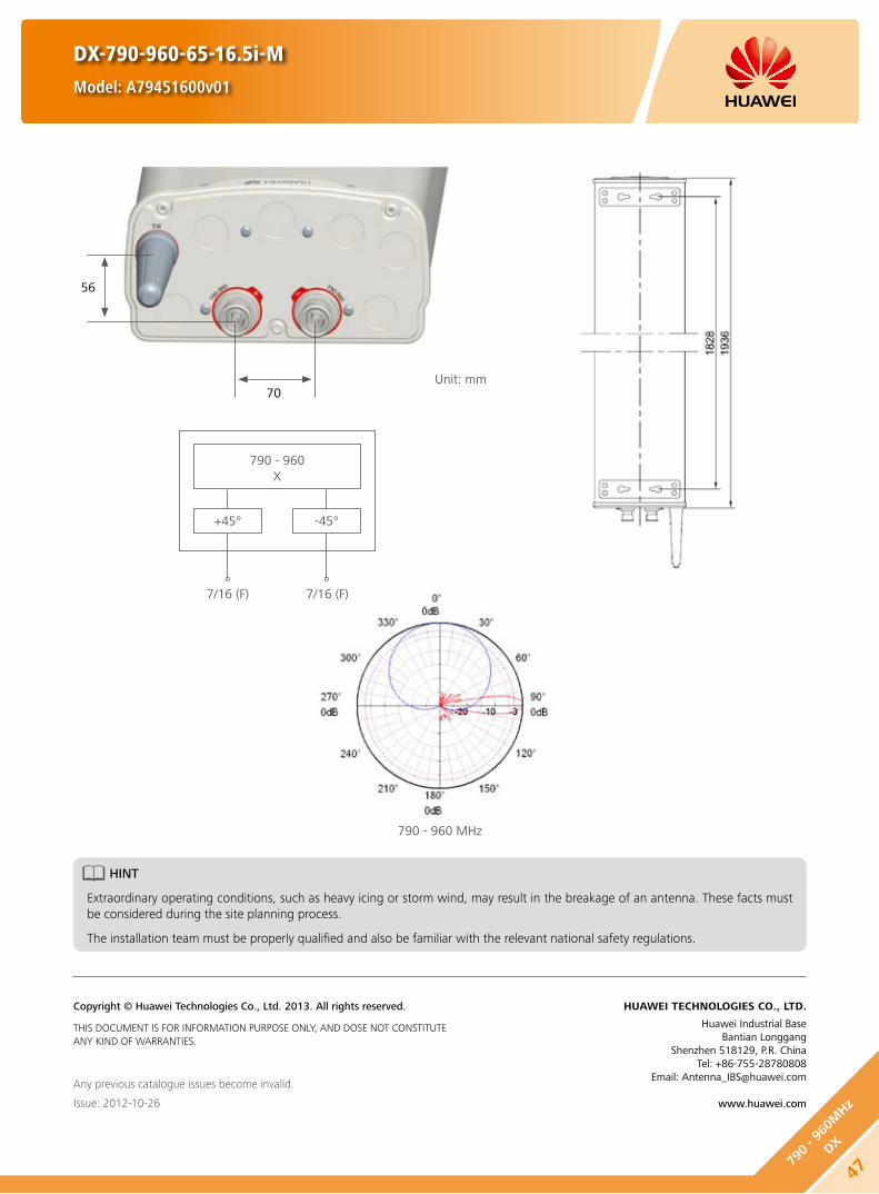
790 - 960 MHz
790 - 960X
+45°
7/16 (F) 7/16 (F)
-45°
DX-790-960-65-16.5i-M
Model: A79451600v01
Unit: mm70
56
HINT
Extraordinary operating conditions, such as heavy icing or storm wind, may result in the breakage of an antenna. These facts must be considered during the site planning process.
The installation team must be properly qualified and also be familiar with the relevant national safety regulations.
Any previous catalogue issues become invalid.
Issue: 2012-10-26
HUAWEI TECHNOLOGIES CO., LTD.
Huawei Industrial BaseBantian Longgang
Shenzhen 518129, P.R. ChinaTel: +86-755-28780808
Email: [email protected]
www.huawei.com
Copyright © Huawei Technologies Co., Ltd. 2013. All rights reserved.
THIS DOCUMENT IS FOR INFORMATION PURPOSE ONLY, AND DOSE NOT CONSTITUTE ANY KIND OF WARRANTIES.
4779
0 - 9
60M
Hz
DX

DX-790-960-65-17.5i-M
Model: A79451700v01
Electrical Properties
Frequency range (MHz)790 - 960
790 - 862 824 - 894 880 - 960
Polarization +45° , -45°
Electrical downtilt (°) 0 - 10, continuously adjustable
Gain (dBi)0° 5° 10° 0° 5° 10° 0° 5° 10°
17.0 17.1 16.7 17.1 17.3 17.0 17.3 17.6 17.1
Side lobe suppression for first side lobe above main beam (Typ.) (dB)
0° 5° 10° 0° 5° 10° 0° 5° 10°
20 18 18 20 20 18 20 18 18
Horizontal 3dB beam width (°) 66 66 64
Vertical 3dB beam width (°) 8.3 7.9 7.3
VSWR < 1.5
Isolation between ports (dB) ≥ 30
Front to back ratio, copolar (dB) Typ. 30
Cross polar ratio (dB)0° Typ. 25
±60° ≥ 10
Max. power per input (W) 500 (at 50 ambient temperature)
Intermodulation IM3 (dBc) ≤ -153 (2 x 43 dBm carrier)
Squint (°) Avg. 1
Tracking (dB) Avg. 1 (within 10dB HBW)
Impedance (Ω) 50
Grounding DC Ground
Mechanical Properties
Antenna dimensions (H x W x D) (mm) 2535 x 259 x 135
Antenna net weight (kg) 17.5
Bracket weight (kg) 5.6
Mechanical downtilt (°) 0 - 8
Mast diameter (mm) 50 - 115
Radome material Fiberglass
Radome colour Light grey
Operational temperature () -55 .. +65
Wind load (N)Frontal: 910 (at 150 km/h)Lateral: 470 (at 150 km/h)
Rear side: 1200 (at 150 km/h)
Max. operational wind speed (km/h) 150
Survival wind speed (km/h) 200
Connector 2 x 7/16 DIN Female
Connector position Bottom
48
790 - 960MHz
DX

790 - 960 MHz
DX-790-960-65-17.5i-M
Model: A79451700v01
HINT
Extraordinary operating conditions, such as heavy icing or storm wind, may result in the breakage of an antenna. These facts must be considered during the site planning process.
The installation team must be properly qualified and also be familiar with the relevant national safety regulations.
Any previous catalogue issues become invalid.
Issue: 2012-10-26
HUAWEI TECHNOLOGIES CO., LTD.
Huawei Industrial BaseBantian Longgang
Shenzhen 518129, P.R. ChinaTel: +86-755-28780808
Email: [email protected]
www.huawei.com
Copyright © Huawei Technologies Co., Ltd. 2013. All rights reserved.
THIS DOCUMENT IS FOR INFORMATION PURPOSE ONLY, AND DOSE NOT CONSTITUTE ANY KIND OF WARRANTIES.
Unit: mm
56
70
790 - 960X
+45°
7/16 (F) 7/16 (F)
-45°
4979
0 - 9
60M
Hz
DX
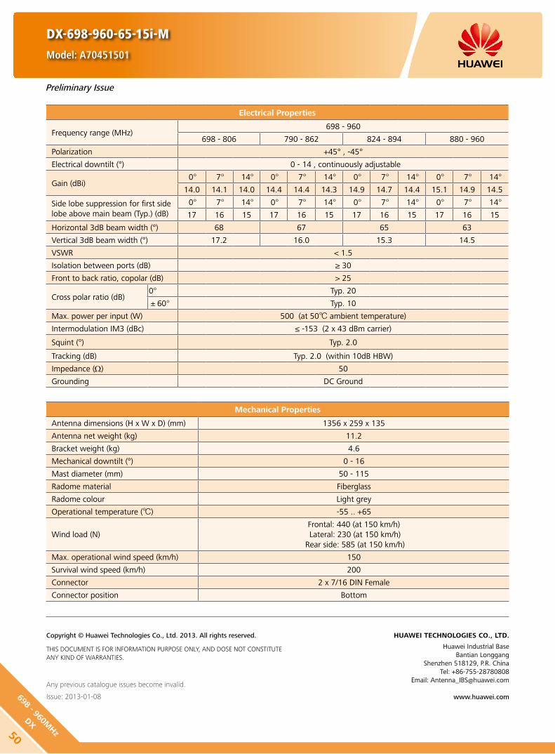
DX-698-960-65-15i-M
Model: A70451501
Preliminary Issue
Electrical Properties
Frequency range (MHz)698 - 960
698 - 806 790 - 862 824 - 894 880 - 960
Polarization +45° , -45°
Electrical downtilt (°) 0 - 14 , continuously adjustable
Gain (dBi)0° 7° 14° 0° 7° 14° 0° 7° 14° 0° 7° 14°
14.0 14.1 14.0 14.4 14.4 14.3 14.9 14.7 14.4 15.1 14.9 14.5
Side lobe suppression for first side lobe above main beam (Typ.) (dB)
0° 7° 14° 0° 7° 14° 0° 7° 14° 0° 7° 14°
17 16 15 17 16 15 17 16 15 17 16 15
Horizontal 3dB beam width (°) 68 67 65 63
Vertical 3dB beam width (°) 17.2 16.0 15.3 14.5
VSWR < 1.5
Isolation between ports (dB) ≥ 30
Front to back ratio, copolar (dB) > 25
Cross polar ratio (dB)0° Typ. 20
±60° Typ. 10
Max. power per input (W) 500 (at 50 ambient temperature)
Intermodulation IM3 (dBc) ≤ -153 (2 x 43 dBm carrier)
Squint (°) Typ. 2.0
Tracking (dB) Typ. 2.0 (within 10dB HBW)
Impedance (Ω) 50
Grounding DC Ground
Mechanical Properties
Antenna dimensions (H x W x D) (mm) 1356 x 259 x 135
Antenna net weight (kg) 11.2
Bracket weight (kg) 4.6
Mechanical downtilt (°) 0 - 16
Mast diameter (mm) 50 - 115
Radome material Fiberglass
Radome colour Light grey
Operational temperature () -55 .. +65
Wind load (N)Frontal: 440 (at 150 km/h) Lateral: 230 (at 150 km/h)
Rear side: 585 (at 150 km/h)
Max. operational wind speed (km/h) 150
Survival wind speed (km/h) 200
Connector 2 x 7/16 DIN Female
Connector position Bottom
Any previous catalogue issues become invalid.
Issue: 2013-01-08
HUAWEI TECHNOLOGIES CO., LTD.
Huawei Industrial BaseBantian Longgang
Shenzhen 518129, P.R. ChinaTel: +86-755-28780808
Email: [email protected]
www.huawei.com
Copyright © Huawei Technologies Co., Ltd. 2013. All rights reserved.
THIS DOCUMENT IS FOR INFORMATION PURPOSE ONLY, AND DOSE NOT CONSTITUTE ANY KIND OF WARRANTIES.
50
698 - 960MHz
DX

Electrical Properties
Frequency range (MHz)698 - 960
698 - 806 790 - 862 824 - 894 880 - 960
Polarization +45° , -45°
Electrical downtilt (°) 0 - 12 , continuously adjustable
Gain (dBi)0° 6° 12° 0° 6° 12° 0° 6° 12° 0° 6° 12°
15.5 15.6 15.3 16.0 16.1 15.8 16.3 16.4 16.0 16.4 16.6 16.1
Side lobe suppression for first side lobe above main beam (Typ.) (dB)
0° 6° 12° 0° 6° 12° 0° 6° 12° 0° 6° 12°
17 16 15 17 16 15 17 16 15 17 16 15
Horizontal 3dB beam width (°) 68 67 65 63
Vertical 3dB beam width (°) 11.5 10.5 10.1 9.5
VSWR < 1.5
Isolation between ports (dB) ≥ 30
Front to back ratio, copolar (dB) Typ. 27
Cross polar ratio (dB)0° Typ. 20
±60° Typ. 10
Max. power per input (W) 500 (at 50 ambient temperature)
Intermodulation IM3 (dBc) ≤ -153 (2 x 43 dBm carrier)
Squint (°) Typ. 2.0
Tracking (dB) Typ. 2.0 (within 10dB HBW)
Impedance (Ω) 50
Grounding DC Ground
Mechanical Properties
Antenna dimensions (H x W x D) (mm) 1936 x 259 x 135
Antenna net weight (kg) 14.5
Bracket weight (kg) 4.6
Mechanical downtilt (°) 0 - 12
Mast diameter (mm) 50 - 115
Radome material Fiberglass
Radome colour Light grey
Operational temperature () -55 .. +65
Wind load (N)Frontal: 665 (at 150 km/h)Lateral: 345 (at 150 km/h)
Rear side: 880 (at 150 km/h)
Max. operational wind speed (km/h) 150
Survival wind speed (km/h) 200
Connector 2 x 7/16 DIN Female
Connector position Bottom
Any previous catalogue issues become invalid.
Issue: 2013-01-08
HUAWEI TECHNOLOGIES CO., LTD.
Huawei Industrial BaseBantian Longgang
Shenzhen 518129, P.R. ChinaTel: +86-755-28780808
Email: [email protected]
www.huawei.com
Copyright © Huawei Technologies Co., Ltd. 2013. All rights reserved.
THIS DOCUMENT IS FOR INFORMATION PURPOSE ONLY, AND DOSE NOT CONSTITUTE ANY KIND OF WARRANTIES.
DX-698-960-65-16.5i-M
Model: A70451600
Preliminary Issue
5169
8 - 9
60M
Hz
DX

DX-698-960-65-17.5i-M
Model: A70451700
Preliminary Issue
Electrical Properties
Frequency range (MHz)698 - 960
698 - 806 790 - 862 824 - 894 880 - 960
Polarization +45° , -45°
Electrical downtilt (°) 0 - 10 , continuously adjustable
Gain (dBi)0° 5° 10° 0° 5° 10° 0° 5° 10° 0° 5° 10°
16.3 16.4 16.0 16.8 16.9 16.5 17.1 17.2 16.8 17.1 17.4 16.9
Side lobe suppression for first side lobe above main beam (Typ.) (dB)
0° 5° 10° 0° 5° 10° 0° 5° 10° 0° 5° 10°
17 16 15 17 16 15 17 16 15 17 16 15
Horizontal 3dB beam width (°) 68 67 65 63
Vertical 3dB beam width (°) 9.0 8.3 7.9 7.3
VSWR < 1.5
Isolation between ports (dB) ≥ 30
Front to back ratio, copolar (dB) Typ. 28
Cross polar ratio (dB)0° Typ. 20
±60° Typ. 10
Max. power per input (W) 500 (at 50 ambient temperature)
Intermodulation IM3 (dBc) ≤ -153 (2 x 43 dBm carrier)
Squint (°) Typ. 2.0
Tracking (dB) Typ. 2.0 (within 10dB HBW)
Impedance (Ω) 50
Grounding DC Ground
Mechanical Properties
Antenna dimensions (H x W x D) (mm) 2535 x 259 x 135
Antenna net weight (kg) 17.5
Bracket weight (kg) 5.6
Mechanical downtilt (°) 0 - 8
Mast diameter (mm) 50 - 115
Radome material Fiberglass
Radome colour Light grey
Operational temperature () -55 .. +65
Wind load (N)Frontal: 910 (at 150 km/h)Lateral: 470 (at 150 km/h)
Rear side: 1200 (at 150 km/h)
Max. operational wind speed (km/h) 150
Survival wind speed (km/h) 200
Connector 2 x 7/16 DIN Female
Connector position Bottom
Any previous catalogue issues become invalid.
Issue: 2013-01-08
HUAWEI TECHNOLOGIES CO., LTD.
Huawei Industrial BaseBantian Longgang
Shenzhen 518129, P.R. ChinaTel: +86-755-28780808
Email: [email protected]
www.huawei.com
Copyright © Huawei Technologies Co., Ltd. 2013. All rights reserved.
THIS DOCUMENT IS FOR INFORMATION PURPOSE ONLY, AND DOSE NOT CONSTITUTE ANY KIND OF WARRANTIES.
52
698 - 960MHz
DX

Electrical Properties
Frequency range (MHz)698 - 960
698 - 806 790 - 862 824 - 894 880 - 960
Polarization +45° , -45°
Electrical downtilt (°) 0 - 12 , continuously adjustable
Gain (dBi)0° 6° 12° 0° 6° 12° 0° 6° 12° 0° 6° 12°
14.4 14.5 14.0 14.9 15.0 14.5 15.0 15.1 14.5 14.9 15.2 14.6
Side lobe suppression for first side lobe above main beam (Typ.) (dB)
0° 6° 12° 0° 6° 12° 0° 6° 12° 0° 6° 12°
17 16 15 17 16 15 17 16 15 17 16 15
Horizontal 3dB beam width (°) 87 86 85 84
Vertical 3dB beam width (°) 11.5 10.5 10.1 9.5
VSWR < 1.5
Isolation between ports (dB) ≥ 30
Front to back ratio, copolar (dB) Typ. 26
Cross polar ratio (dB)0° Typ. 17
±60° Typ. 10
Max. power per input (W) 500 (at 50 ambient temperature)
Intermodulation IM3 (dBc) ≤ -153 (2 x 43 dBm carrier)
Squint (°) Avg. 2.0
Tracking (dB) Avg. 2.0 (within 10dB HBW)
Impedance (Ω) 50
Grounding DC Ground
Mechanical Properties
Antenna dimensions (H x W x D) (mm) 1936 x 259 x 135
Antenna net weight (kg) 12.5
Bracket weight (kg) 4.6
Mechanical downtilt (°) 0 - 12
Mast diameter (mm) 50 - 115
Radome material Fiberglass
Radome colour Light grey
Operational temperature () -55 .. +65
Wind load (N)Frontal: 665 (at 150 km/h)Lateral: 345 (at 150 km/h)
Rear side: 880 (at 150 km/h)
Max. operational wind speed (km/h) 150
Survival wind speed (km/h) 200
Connector 2 x 7/16 DIN Female
Connector position Bottom
Any previous catalogue issues become invalid.
Issue: 2013-01-08
HUAWEI TECHNOLOGIES CO., LTD.
Huawei Industrial BaseBantian Longgang
Shenzhen 518129, P.R. ChinaTel: +86-755-28780808
Email: [email protected]
www.huawei.com
Copyright © Huawei Technologies Co., Ltd. 2013. All rights reserved.
THIS DOCUMENT IS FOR INFORMATION PURPOSE ONLY, AND DOSE NOT CONSTITUTE ANY KIND OF WARRANTIES.
DX-698-960-90-15i-M
Model: A70451500
Preliminary Issue
5369
8 - 9
60M
Hz
DX
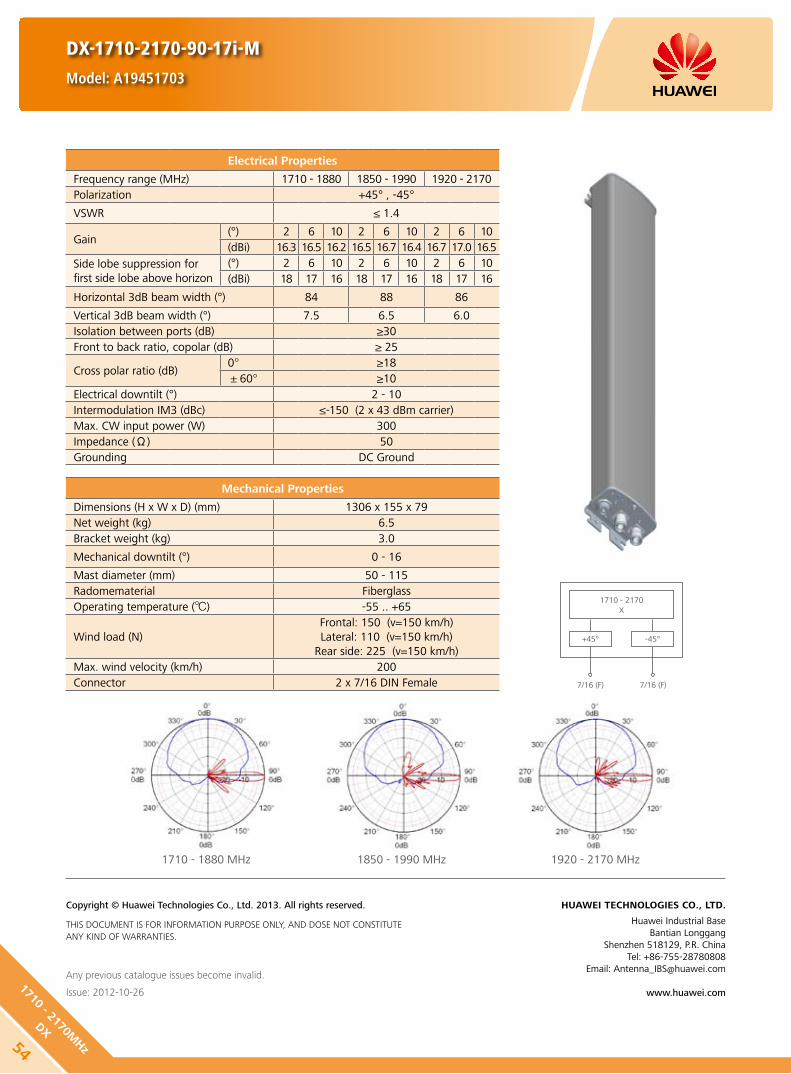
1710 - 2170X
+45°
7/16 (F) 7/16 (F)
-45°
DX-1710-2170-90-17i-M
Model: A19451703
Any previous catalogue issues become invalid.
Issue: 2012-10-26
HUAWEI TECHNOLOGIES CO., LTD.
Huawei Industrial BaseBantian Longgang
Shenzhen 518129, P.R. ChinaTel: +86-755-28780808
Email: [email protected]
www.huawei.com
Copyright © Huawei Technologies Co., Ltd. 2013. All rights reserved.
THIS DOCUMENT IS FOR INFORMATION PURPOSE ONLY, AND DOSE NOT CONSTITUTE ANY KIND OF WARRANTIES.
Mechanical Properties
Dimensions (H x W x D) (mm) 1306 x 155 x 79Net weight (kg) 6.5Bracket weight (kg) 3.0
Mechanical downtilt (°) 0 - 16
Mast diameter (mm) 50 - 115Radomematerial FiberglassOperating temperature () -55 .. +65
Wind load (N)Frontal: 150 (v=150 km/h)Lateral: 110 (v=150 km/h)
Rear side: 225 (v=150 km/h)Max. wind velocity (km/h) 200Connector 2 x 7/16 DIN Female
Electrical Properties
Frequency range (MHz) 1710 - 1880 1850 - 1990 1920 - 2170Polarization +45° , -45°
VSWR ≤ 1.4
Gain (°) 2 6 10 2 6 10 2 6 10(dBi) 16.3 16.5 16.2 16.5 16.7 16.4 16.7 17.0 16.5
Side lobe suppression for first side lobe above horizon
(°) 2 6 10 2 6 10 2 6 10(dBi) 18 17 16 18 17 16 18 17 16
Horizontal 3dB beam width (°) 84 88 86
Vertical 3dB beam width (°) 7.5 6.5 6.0Isolation between ports (dB) ≥30Front to back ratio, copolar (dB) ≥ 25
Cross polar ratio (dB)0° ≥18±60° ≥10
Electrical downtilt (°) 2 - 10Intermodulation IM3 (dBc) ≤-150 (2 x 43 dBm carrier)Max. CW input power (W) 300Impedance (Ω) 50Grounding DC Ground
1710 - 1880 MHz 1850 - 1990 MHz 1920 - 2170 MHz
54
1710 - 2170MHz
DX

DX-1710-2170-33-21i-M
Model: A19452101
Any previous catalogue issues become invalid.
Issue: 2012-10-26
HUAWEI TECHNOLOGIES CO., LTD.
Huawei Industrial BaseBantian Longgang
Shenzhen 518129, P.R. ChinaTel: +86-755-28780808
Email: [email protected]
www.huawei.com
Copyright © Huawei Technologies Co., Ltd. 2013. All rights reserved.
THIS DOCUMENT IS FOR INFORMATION PURPOSE ONLY, AND DOSE NOT CONSTITUTE ANY KIND OF WARRANTIES.
Mechanical Properties
Dimensions (H x W x D) (mm) 1318 x 289 x 85Net weight (kg) 11.4Bracket weight (kg) 4.6
Mechanical downtilt (°) 0 - 8
Mast diameter (mm) 50 - 115Radomematerial FiberglassOperating temperature () -55 .. +65
Wind load (N)Frontal: 285 (v=150 km/h)Lateral: 120 (v=150 km/h)
Rear side: 425 (v=150 km/h)Max. wind velocity (km/h) 200Connector 2 x 7/16 DIN Female
Electrical Properties
Frequency range (MHz) 1710 - 1880 1850 - 1990 1920 - 2170Polarization +45° , -45°
VSWR ≤ 1.45
Gain (°) 2 6 10 2 6 10 2 6 10(dBi) 20.0 20.1 20.1 20.3 20.5 20.1 20.7 20.5 19.8
Side lobe suppression for first side lobe above horizon
(°) 2 6 10 2 6 10 2 6 10(dBi) 18 17 16 18 17 16 18 17 16
Horizontal 3dB beam width (°) 35 33 31
Vertical 3dB beam width (°) 7.2 6.6 6.2Isolation between ports (dB) ≥30Front to back ratio, copolar (dB) Typ. 28Cross polar ratio (dB) Typ. 20Electrical downtilt (°) 0 - 10Intermodulation IM3 (dBc) ≤-150 (2 x 43 dBm carrier)Max. CW input power (W) 300Impedance (Ω) 50Grounding DC Ground
1710 - 1880 MHz 1850 - 1990 MHz 1920 - 2170 MHz
1710 - 2170X
+45°
7/16 (F) 7/16 (F)
-45°
551710
- 21
70M
Hz
DX
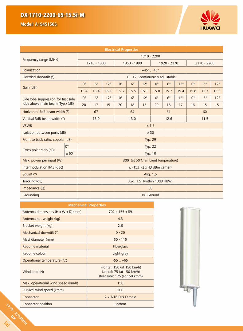
Mechanical Properties
Antenna dimensions (H x W x D) (mm) 702 x 155 x 89
Antenna net weight (kg) 4.3
Bracket weight (kg) 2.6
Mechanical downtilt (°) 0 - 20
Mast diameter (mm) 50 - 115
Radome material Fiberglass
Radome colour Light grey
Operational temperature () -55 .. +65
Wind load (N) Frontal: 150 (at 150 km/h) Lateral: 75 (at 150 km/h)
Rear side: 175 (at 150 km/h)
Max. operational wind speed (km/h) 150
Survival wind speed (km/h) 200
Connector 2 x 7/16 DIN Female
Connector position Bottom
DX-1710-2200-65-15.5i-M
Model: A19451505
Electrical Properties
Frequency range (MHz)1710 - 2200
1710 - 1880 1850 - 1990 1920 - 2170 2170 - 2200
Polarization +45° , -45°
Electrical downtilt (°) 0 - 12 , continuously adjustable
Gain (dBi)0° 6° 12° 0° 6° 12° 0° 6° 12° 0° 6° 12°
15.4 15.4 15.1 15.6 15.5 15.1 15.8 15.7 15.4 15.8 15.7 15.3
Side lobe suppression for first side lobe above main beam (Typ.) (dB)
0° 6° 12° 0° 6° 12° 0° 6° 12° 0° 6° 12°
20 17 15 20 18 15 20 18 17 16 15 15
Horizontal 3dB beam width (°) 67 64 61 60
Vertical 3dB beam width (°) 13.9 13.0 12.6 11.5
VSWR < 1.5
Isolation between ports (dB) ≥ 30
Front to back ratio, copolar (dB) Typ. 29
Cross polar ratio (dB)0° Typ. 22
±60° Typ. 10
Max. power per input (W) 300 (at 50 ambient temperature)
Intermodulation IM3 (dBc) ≤ -153 (2 x 43 dBm carrier)
Squint (°) Avg. 1.5
Tracking (dB) Avg. 1.5 (within 10dB HBW)
Impedance (Ω) 50
Grounding DC Ground
56
1710 - 2200MHz
DX

DX-1710-2200-65-15.5i-M
Model: A19451505
HINT
Extraordinary operating conditions, such as heavy icing or storm wind, may result in the breakage of an antenna. These facts must be considered during the site planning process.
The installation team must be properly qualified and also be familiar with the relevant national safety regulations.
Any previous catalogue issues become invalid.
Issue: 2012-10-26
HUAWEI TECHNOLOGIES CO., LTD.
Huawei Industrial BaseBantian Longgang
Shenzhen 518129, P.R. ChinaTel: +86-755-28780808
Email: [email protected]
www.huawei.com
Copyright © Huawei Technologies Co., Ltd. 2013. All rights reserved.
THIS DOCUMENT IS FOR INFORMATION PURPOSE ONLY, AND DOSE NOT CONSTITUTE ANY KIND OF WARRANTIES.
1710 - 2200 MHz
1710 - 2200X
+45°
7/16 (F) 7/16 (F)
-45°
Unit: mm3446
34
571710
- 22
00M
Hz
DX

Electrical Properties
Frequency range (MHz)1710 - 2200
1710 - 1880 1850 - 1990 1920 - 2170 2170 - 2200
Polarization +45° , -45°
Electrical downtilt (°) 0 - 10, continuously adjustable
Gain (dBi)0° 5° 10° 0° 5° 10° 0° 5° 10° 0° 5° 10°
17.2 17.6 17.4 17.7 18.0 17.7 18.0 18.1 17.9 18.0 18.2 17.9
Side lobe suppression for first side lobe above main beam (Typ.) (dB)
0° 5° 10° 0° 5° 10° 0° 5° 10° 0° 5° 10°
20 16 18 20 20 18 18 17 16 18 18 16
Horizontal 3dB beam width (°) 67 64 61 60
Vertical 3dB beam width (°) 7.5 7.0 6.7 6.2
VSWR < 1.5
Isolation between ports (dB) ≥ 30
Front to back ratio, copolar (dB) Typ. 30
Cross polar ratio (dB)0° Typ. 22
±60° ≥ 10
Max. power per input (W) 500 (at 50 ambient temperature)
Intermodulation IM3 (dBc) ≤ -153 (2 x 43 dBm carrier)
Squint (°) Avg. 1.2
Tracking (dB) Avg. 1.2 (within 10dB HBW)
Impedance (Ω) 50
Grounding DC Ground
Mechanical Properties
Antenna dimensions (H x W x D) (mm) 1311 x 155 x 89
Antenna net weight (kg) 6.2
Bracket weight (kg) 2.6
Mechanical downtilt (°) 0 - 12
Mast diameter (mm) 50 - 115
Radome material Fiberglass
Radome colour Light grey
Operational temperature () -55 .. +65
Wind load (N)Frontal: 315 (at 150 km/h)Lateral: 155 (at 150 km/h)
Rear side: 360 (at 150 km/h)
Max. operational wind speed (km/h) 150
Survival wind speed (km/h) 200
Connector 2 x 7/16 DIN Female
Connector position Bottom
DX-1710-2200-65-18i-M
Model: A19451811
58
1710 - 2200MHz
DX

1710 - 2200 MHz
DX-1710-2200-65-18i-M
Model: A19451811
Unit: mm3446
34
HINT
Extraordinary operating conditions, such as heavy icing or storm wind, may result in the breakage of an antenna. These facts must be considered during the site planning process.
The installation team must be properly qualified and also be familiar with the relevant national safety regulations.
Any previous catalogue issues become invalid.
Issue: 2012-10-26
HUAWEI TECHNOLOGIES CO., LTD.
Huawei Industrial BaseBantian Longgang
Shenzhen 518129, P.R. ChinaTel: +86-755-28780808
Email: [email protected]
www.huawei.com
Copyright © Huawei Technologies Co., Ltd. 2013. All rights reserved.
THIS DOCUMENT IS FOR INFORMATION PURPOSE ONLY, AND DOSE NOT CONSTITUTE ANY KIND OF WARRANTIES.
1710 - 2200X
+45°
7/16 (F) 7/16 (F)
-45°
591710
- 22
00M
Hz
DX

Electrical Properties
Frequency range (MHz)1710 - 2200
1710 - 1880 1850 - 1990 1920 - 2170 2170 - 2200
Polarization +45° , -45°
Electrical downtilt (°) 0 - 10 , continuously adjustable
Gain (dBi)0° 5° 10° 0° 5° 10° 0° 5° 10° 0° 5° 10°
17.2 17.4 17.1 17.5 17.8 17.4 17.8 18.1 17.6 17.4 17.6 17.5
Side lobe suppression for first side lobe above main beam (Typ.) (dB)
0° 5° 10° 0° 5° 10° 0° 5° 10° 0° 5° 10°
18 15 16 18 17 16 18 17 16 18 17 16
Horizontal 3dB beam width (°) 67 64 61 60
Vertical 3dB beam width (°) 7.5 7.0 6.7 6.2
VSWR < 1.5
Isolation between ports (dB) ≥ 30
Front to back ratio, copolar (dB) Typ. 30
Cross polar ratio (dB)0° Typ. 20
±60° Typ. 10
Max. power per input (W) 300 (at 50 ambient temperature)
Intermodulation IM3 (dBc) ≤ -153 (2 x 43 dBm carrier)
Squint (°) Typ. 3
Tracking (dB) Typ. 3 (within 10dB HBW)
Impedance (Ω) 50
Grounding DC Ground
Mechanical Properties
Antenna dimensions (H x W x D) (mm) 1315 x 155 x 89
Antenna net weight (kg) 7
Bracket weight (kg) 2.6
Mechanical downtilt (°) 0 - 12
Mast diameter (mm) 50 - 115
Radome material Fiberglass
Radome colour Light grey
Operational temperature () -40 .. +65
Wind load (N)Frontal: 150 (at 150 km/h) Lateral: 110 (at 150 km/h)
Rear side: 225 (at 150 km/h)
Max. operational wind speed (km/h) 150
Survival wind speed (km/h) 200
Connector 2 x 7/16 DIN Female
Connector position Bottom
RET Type Internal motor
RET Protocols AISG 1.1 / AISG 2.0
RET Connector2 x 8 pin connector according to IEC 60130-9Daisy chain in: Male / Daisy chain out: Female
DX-1710-2200-65-18i-M-R
Model: A194518R0
60
1710 - 2200MHz
DX
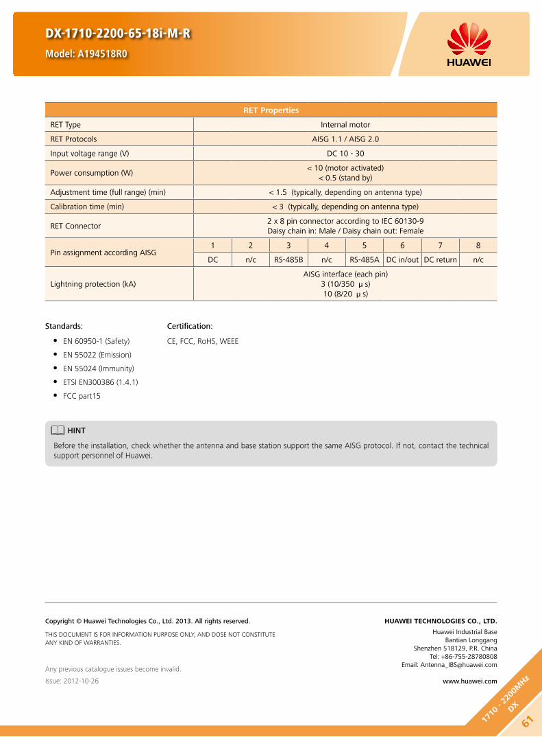
RET Properties
RET Type Internal motor
RET Protocols AISG 1.1 / AISG 2.0
Input voltage range (V) DC 10 - 30
Power consumption (W) < 10 (motor activated)
< 0.5 (stand by)
Adjustment time (full range) (min) < 1.5 (typically, depending on antenna type)
Calibration time (min) < 3 (typically, depending on antenna type)
RET Connector2 x 8 pin connector according to IEC 60130-9Daisy chain in: Male / Daisy chain out: Female
Pin assignment according AISG 1 2 3 4 5 6 7 8
DC n/c RS-485B n/c RS-485A DC in/out DC return n/c
Lightning protection (kA)AISG interface (each pin)
3 (10/350 μs)10 (8/20 μs)
DX-1710-2200-65-18i-M-R
Model: A194518R0
HINT
Before the installation, check whether the antenna and base station support the same AISG protocol. If not, contact the technical support personnel of Huawei.
Standards:
EN 60950-1 (Safety) y
EN 55022 (Emission) y
EN 55024 (Immunity) y
ETSI EN300386 (1.4.1) y
FCC part15 y
Certification:
CE, FCC, RoHS, WEEE
Any previous catalogue issues become invalid.
Issue: 2012-10-26
HUAWEI TECHNOLOGIES CO., LTD.
Huawei Industrial BaseBantian Longgang
Shenzhen 518129, P.R. ChinaTel: +86-755-28780808
Email: [email protected]
www.huawei.com
Copyright © Huawei Technologies Co., Ltd. 2013. All rights reserved.
THIS DOCUMENT IS FOR INFORMATION PURPOSE ONLY, AND DOSE NOT CONSTITUTE ANY KIND OF WARRANTIES.
611710
- 22
00M
Hz
DX
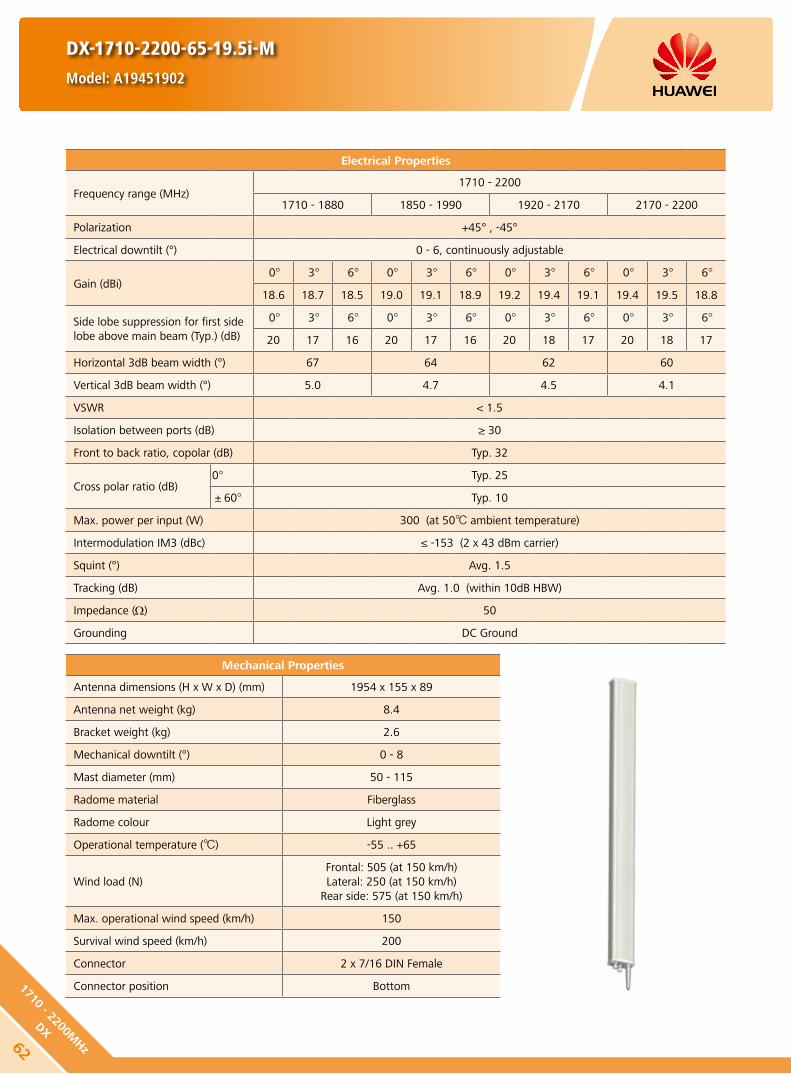
DX-1710-2200-65-19.5i-M
Model: A19451902
Electrical Properties
Frequency range (MHz)1710 - 2200
1710 - 1880 1850 - 1990 1920 - 2170 2170 - 2200
Polarization +45° , -45°
Electrical downtilt (°) 0 - 6, continuously adjustable
Gain (dBi)0° 3° 6° 0° 3° 6° 0° 3° 6° 0° 3° 6°
18.6 18.7 18.5 19.0 19.1 18.9 19.2 19.4 19.1 19.4 19.5 18.8
Side lobe suppression for first side lobe above main beam (Typ.) (dB)
0° 3° 6° 0° 3° 6° 0° 3° 6° 0° 3° 6°
20 17 16 20 17 16 20 18 17 20 18 17
Horizontal 3dB beam width (°) 67 64 62 60
Vertical 3dB beam width (°) 5.0 4.7 4.5 4.1
VSWR < 1.5
Isolation between ports (dB) ≥ 30
Front to back ratio, copolar (dB) Typ. 32
Cross polar ratio (dB)0° Typ. 25
±60° Typ. 10
Max. power per input (W) 300 (at 50 ambient temperature)
Intermodulation IM3 (dBc) ≤ -153 (2 x 43 dBm carrier)
Squint (°) Avg. 1.5
Tracking (dB) Avg. 1.0 (within 10dB HBW)
Impedance (Ω) 50
Grounding DC Ground
Mechanical Properties
Antenna dimensions (H x W x D) (mm) 1954 x 155 x 89
Antenna net weight (kg) 8.4
Bracket weight (kg) 2.6
Mechanical downtilt (°) 0 - 8
Mast diameter (mm) 50 - 115
Radome material Fiberglass
Radome colour Light grey
Operational temperature () -55 .. +65
Wind load (N)Frontal: 505 (at 150 km/h)Lateral: 250 (at 150 km/h)
Rear side: 575 (at 150 km/h)
Max. operational wind speed (km/h) 150
Survival wind speed (km/h) 200
Connector 2 x 7/16 DIN Female
Connector position Bottom
62
1710 - 2200MHz
DX

DX-1710-2200-65-19.5i-M
Model: A19451902
Unit: mm3446
34
1710 - 2200 MHz
HINT
Extraordinary operating conditions, such as heavy icing or storm wind, may result in the breakage of an antenna. These facts must be considered during the site planning process.
The installation team must be properly qualified and also be familiar with the relevant national safety regulations.
Any previous catalogue issues become invalid.
Issue: 2012-10-26
HUAWEI TECHNOLOGIES CO., LTD.
Huawei Industrial BaseBantian Longgang
Shenzhen 518129, P.R. ChinaTel: +86-755-28780808
Email: [email protected]
www.huawei.com
Copyright © Huawei Technologies Co., Ltd. 2013. All rights reserved.
THIS DOCUMENT IS FOR INFORMATION PURPOSE ONLY, AND DOSE NOT CONSTITUTE ANY KIND OF WARRANTIES.
1710 - 2200X
+45°
7/16 (F) 7/16 (F)
-45°
631710
- 22
00M
Hz
DX

Mechanical Properties
Antenna dimensions (H x W x D) (mm) 790 x 155 x 109
Antenna net weight (kg) 5.5
Bracket weight (kg) 2.6
Mechanical downtilt (°) 0 - 16
Mast diameter (mm) 50 - 115
Radome material Fiberglass
Radome colour Light grey
Operational temperature () -55 .. +65
Wind load (N)Frontal: 170 (at 150 km/h)Lateral: 85 (at 150 km/h)
Rear side: 195 (at 150 km/h)
Max. operational wind speed (km/h) 150
Survival wind speed (km/h) 200
Connector 2 x 7/16 DIN Female
Connector position Bottom
Any previous catalogue issues become invalid.
Issue: 2013-01-08
HUAWEI TECHNOLOGIES CO., LTD.
Huawei Industrial BaseBantian Longgang
Shenzhen 518129, P.R. ChinaTel: +86-755-28780808
Email: [email protected]
www.huawei.com
Copyright © Huawei Technologies Co., Ltd. 2013. All rights reserved.
THIS DOCUMENT IS FOR INFORMATION PURPOSE ONLY, AND DOSE NOT CONSTITUTE ANY KIND OF WARRANTIES.
Electrical Properties
Frequency range (MHz)1710 - 2690
1710 - 1990 1920 - 2200 2200 - 2490 2490 - 2690
Polarization +45° , -45°
Electrical downtilt (°) 0 - 14 , continuously adjustable
Gain (dBi)0° 7° 14° 0° 7° 14° 0° 7° 14° 0° 7° 14°
14.8 15.0 14.5 15.3 15.5 15.0 15.8 16.0 15.5 15.8 16.0 15.5
Side lobe suppression (Typ.) (dB)
-for first side lobe above main beam
-within 0° - 15° sector above horizon
0° 7° 14° 0° 7° 14° 0° 7° 14° 0° 7° 14°
17 16 15 17 16 15 17 16 15 17 16 15
16 15 15 16 15 15 16 16 15 16 15 15
Horizontal 3dB beam width (°) 67 65 63 60
Vertical 3dB beam width (°) 12 11 10 9
VSWR < 1.5
Isolation between ports (dB) ≥ 30
Front to back ratio, copolar (dB) Typ. 28
Cross polar ratio (dB)0° Typ. 20
±60° Typ. 10
Max. power per input (W) 250 (at 50 ambient temperature)
Intermodulation IM3 (dBc) ≤ -153 (2 x 43 dBm carrier)
Impedance (Ω) 50
Grounding DC Ground
DX-1710-2690-65-16i-M
Model: A26451500
Preliminary Issue
64
1710 - 2690MHz
DX

Electrical Properties
Frequency range (MHz)1710 - 2690
1710 - 1990 1920 - 2200 2200 - 2490 2490 - 2690
Polarization +45° , -45°
Electrical downtilt (°) 0 - 12 , continuously adjustable
Gain (dBi)0° 6° 12° 0° 6° 12° 0° 6° 12° 0° 6° 12°
17.3 17.4 17.2 17.6 17.8 17.5 17.7 18.0 17.5 17.8 18.0 17.3
Side lobe suppression (Typ.) (dB)
-for first side lobe above main beam
-within 0° - 15° sector above horizon
0° 6° 12° 0° 6° 12° 0° 6° 12° 0° 6° 12°
18 17 16 18 17 16 18 17 16 17 17 16
16 16 15 16 16 15 16 16 15 15 16 15
Horizontal 3dB beam width (°) 66 63 60 60
Vertical 3dB beam width (°) 6.7 6.1 5.5 4.9
VSWR < 1.5
Isolation between ports (dB) ≥ 30
Front to back ratio, copolar (dB) Typ. 30
Cross polar ratio (dB)0° Typ. 20
±60° Typ. 10
Max. power per input (W) 250 (at 50 ambient temperature)
Intermodulation IM3 (dBc) ≤ -153 (2 x 43 dBm carrier)
Squint (°) Typ. 3.0
Tracking (dB) Avg. 2.0 (within 10dB HBW)
Impedance (Ω) 50
Grounding DC Ground
Mechanical Properties
Antenna dimensions (H x W x D) (mm) 1365 x 155 x 109
Antenna net weight (kg) 6.7
Bracket weight (kg) 2.6
Mechanical downtilt (°) 0 - 12
Mast diameter (mm) 50 - 115
Radome material Fiberglass
Radome colour Light grey
Operational temperature () -55 .. +65
Wind load (N)Frontal: 215 (at 150 km/h)Lateral: 200 (at 150 km/h)
Rear side: 370 (at 150 km/h)
Max. operational wind speed (km/h) 150
Survival wind speed (km/h) 200
Connector 2 x 7/16 DIN Female
Connector position Bottom
DX-1710-2690-65-18i-M
Model: A26451800v01
Preliminary Issue
651710
- 26
90M
Hz
DX
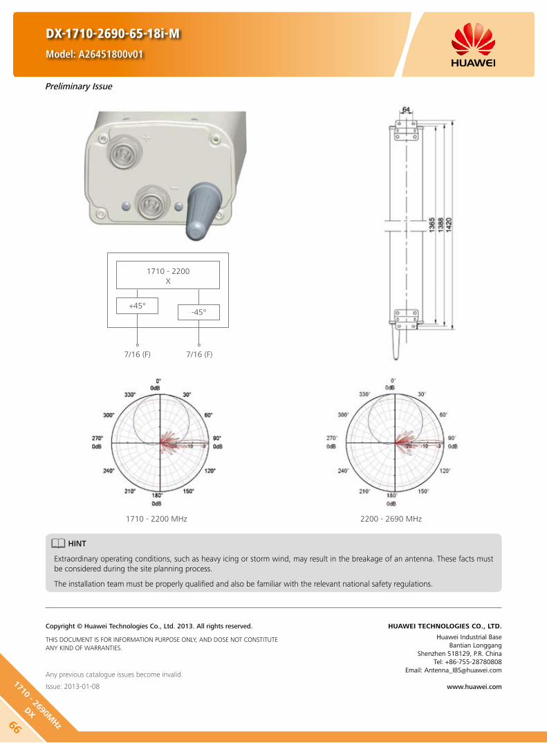
1710 - 2200X
+45°
7/16 (F) 7/16 (F)
-45°
1710 - 2200 MHz 2200 - 2690 MHz
DX-1710-2690-65-18i-M
Model: A26451800v01
Any previous catalogue issues become invalid.
Issue: 2013-01-08
HUAWEI TECHNOLOGIES CO., LTD.
Huawei Industrial BaseBantian Longgang
Shenzhen 518129, P.R. ChinaTel: +86-755-28780808
Email: [email protected]
www.huawei.com
Copyright © Huawei Technologies Co., Ltd. 2013. All rights reserved.
THIS DOCUMENT IS FOR INFORMATION PURPOSE ONLY, AND DOSE NOT CONSTITUTE ANY KIND OF WARRANTIES.
Preliminary Issue
66
1710 - 2690MHz
DX
HINT
Extraordinary operating conditions, such as heavy icing or storm wind, may result in the breakage of an antenna. These facts must be considered during the site planning process.
The installation team must be properly qualified and also be familiar with the relevant national safety regulations.

Electrical Properties
Frequency range (MHz)1710 - 2690
1710 - 1990 1920 - 2200 2200 - 2490 2490 - 2690
Polarization +45° , -45°
Electrical downtilt (°) 0 - 12, continuously adjustable
Gain (dBi)0° 6° 12° 0° 6° 12° 0° 6° 12° 0° 6° 12°
17.3 17.4 17.2 17.6 17.8 17.5 17.7 18.0 17.5 17.8 18.0 17.3
Side lobe suppression (Typ.) (dB)
-for first side lobe above main beam
-within 0° - 15° sector above horizon
0° 6° 12° 0° 6° 12° 0° 6° 12° 0° 6° 12°
18 17 16 18 17 16 18 17 16 17 17 16
16 16 15 16 16 15 16 16 15 15 16 15
Horizontal 3dB beam width (°) 66 63 60 60
Vertical 3dB beam width (°) 6.7 6.1 5.5 4.9
VSWR < 1.5
Isolation between ports (dB) ≥ 30
Front to back ratio, copolar (dB) Typ. 30
Cross polar ratio (dB)0° Typ. 20
±60° Typ. 10
Max. power per input (W) 250 (at 50 ambient temperature)
Intermodulation IM3 (dBc) ≤ -153 (2 x 43 dBm carrier)
Squint (°) Typ. 3.0
Tracking (dB) Avg. 2.0 (within 10dB HBW)
Impedance (Ω) 50
Grounding DC Ground
Mechanical Properties
Antenna dimensions (H x W x D) (mm) 1365 x 155 x 109
Antenna net weight (kg) 7.6
Bracket weight (kg) 2.6
Mechanical downtilt (°) 0 - 12
Mast diameter (mm) 50 - 115
Radome material Fiberglass
Radome colour Light grey
Operational temperature () -40 .. +65
Wind load (N)Frontal: 210 (at 150 km/h)Lateral: 170 (at 150 km/h)
Rear side: 370 (at 150 km/h)
Max. operational wind speed (km/h) 150
Survival wind speed (km/h) 200
Connector 2 x 7/16 DIN Female
Connector position Bottom
Preliminary Issue
DX-1710-2690-65-18i-M-REasyRET Single-Band Antenna with 1 Integrated RCU - 1.4mModel: A264518R0
671710
- 26
90M
Hz
DX

RET Properties
RET Type Integrated RET
RET Protocols* AISG 2.0 / 3GPP
Input voltage range (V) DC 10 - 30
Power consumption (W) < 10 (motor activated)
< 0.5 (stand by)
Adjustment time (full range) (min) < 50 (typically, depending on antenna type)
RET Connector2 x 8 pin connector according to IEC 60130-9Daisy chain in: Male / Daisy chain out: Female
Pin assignment according AISG 1 2 3 4 5 6 7 8
DC n/c RS-485B n/c RS-485A DC in/out DC return n/c
Lightning protection (kA)AISG interface (each pin)
3 (10/350 μs)10 (8/20 μs)
HINT
Before the installation, check whether the antenna and base station support the same AISG protocol. If not, contact the technical support personnel of Huawei.
Any previous catalogue issues become invalid.
Issue: 2013-01-08
HUAWEI TECHNOLOGIES CO., LTD.
Huawei Industrial BaseBantian Longgang
Shenzhen 518129, P.R. ChinaTel: +86-755-28780808
Email: [email protected]
www.huawei.com
Copyright © Huawei Technologies Co., Ltd. 2013. All rights reserved.
THIS DOCUMENT IS FOR INFORMATION PURPOSE ONLY, AND DOSE NOT CONSTITUTE ANY KIND OF WARRANTIES.
Preliminary Issue
DX-1710-2690-65-18i-M-REasyRET Single-Band Antenna with 1 Integrated RCU - 1.4mModel: A264518R0
* Please confirm the AISG protocol of primary station is compatible with RET antenna protocol interface. The protocol of RET antenna software interface is switchable between AISG 2.0/3GPP and AISG 1.1 with a vendor defined command. For more details about protocol switching function, contact Huawei before system installation.
Standards: EN 60950-1 (Safety), EN 55022 (Emission), EN 55024 (Immunity), ETSI EN300386 (1.4.1), FCC part15
Certification: CE, FCC, RoHS, WEEE
68
1710 - 2690MHz
DX
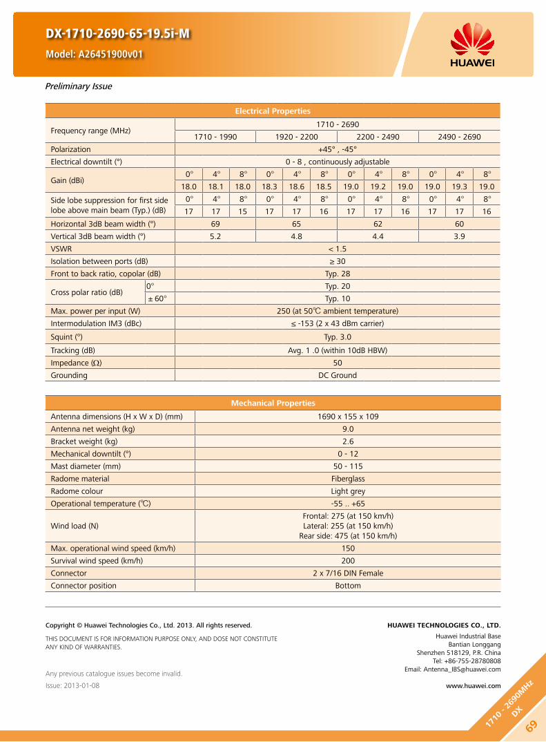
Preliminary Issue
Electrical Properties
Frequency range (MHz)1710 - 2690
1710 - 1990 1920 - 2200 2200 - 2490 2490 - 2690
Polarization +45° , -45°
Electrical downtilt (°) 0 - 8 , continuously adjustable
Gain (dBi)0° 4° 8° 0° 4° 8° 0° 4° 8° 0° 4° 8°
18.0 18.1 18.0 18.3 18.6 18.5 19.0 19.2 19.0 19.0 19.3 19.0
Side lobe suppression for first side lobe above main beam (Typ.) (dB)
0° 4° 8° 0° 4° 8° 0° 4° 8° 0° 4° 8°
17 17 15 17 17 16 17 17 16 17 17 16
Horizontal 3dB beam width (°) 69 65 62 60
Vertical 3dB beam width (°) 5.2 4.8 4.4 3.9
VSWR < 1.5
Isolation between ports (dB) ≥ 30
Front to back ratio, copolar (dB) Typ. 28
Cross polar ratio (dB)0° Typ. 20
±60° Typ. 10
Max. power per input (W) 250 (at 50 ambient temperature)
Intermodulation IM3 (dBc) ≤ -153 (2 x 43 dBm carrier)
Squint (°) Typ. 3.0
Tracking (dB) Avg. 1 .0 (within 10dB HBW)
Impedance (Ω) 50
Grounding DC Ground
Mechanical Properties
Antenna dimensions (H x W x D) (mm) 1690 x 155 x 109
Antenna net weight (kg) 9.0
Bracket weight (kg) 2.6
Mechanical downtilt (°) 0 - 12
Mast diameter (mm) 50 - 115
Radome material Fiberglass
Radome colour Light grey
Operational temperature () -55 .. +65
Wind load (N)Frontal: 275 (at 150 km/h)Lateral: 255 (at 150 km/h)
Rear side: 475 (at 150 km/h)
Max. operational wind speed (km/h) 150
Survival wind speed (km/h) 200
Connector 2 x 7/16 DIN Female
Connector position Bottom
Any previous catalogue issues become invalid.
Issue: 2013-01-08
HUAWEI TECHNOLOGIES CO., LTD.
Huawei Industrial BaseBantian Longgang
Shenzhen 518129, P.R. ChinaTel: +86-755-28780808
Email: [email protected]
www.huawei.com
Copyright © Huawei Technologies Co., Ltd. 2013. All rights reserved.
THIS DOCUMENT IS FOR INFORMATION PURPOSE ONLY, AND DOSE NOT CONSTITUTE ANY KIND OF WARRANTIES.
DX-1710-2690-65-19.5i-M
Model: A26451900v01
691710
- 26
90M
Hz
DX

Electrical Properties
Frequency range (MHz) 790 - 862 880 - 960
Polarization +45° , -45°
Electrical downtilt (°) 0 - 12, continuously adjustable 0 - 14, continuously adjustable
Gain (dBi)0° 7° 14° 0° 7° 14°
14.3 14.1 13.7 14.7 14.5 14.2
Side lobe suppression for first side lobe above main beam (Typ.) (dB)
0° 7° 14° 0° 7° 14°
16 15 15 16 15 15
Horizontal 3dB beam width (°) 66 61
Vertical 3dB beam width (°) 16.6 14.4
VSWR < 1.5
Isolation between ports (dB) ≥ 30
Front to back ratio, copolar (dB) ≥ 25
Cross polar ratio (dB)0° Typ. 20 Typ. 20
±60° ≥ 10 Typ. 10
Max. power per input (W) 500 (at 50 ambient temperature)
Intermodulation IM3 (dBc) ≤ -153 (2 x 43 dBm carrier)
Impedance (Ω) 50
Grounding DC Ground
Mechanical Properties
Antenna dimensions (H x W x D) (mm) 1536 x 349 x 166
Antenna net weight (kg) 19
Bracket weight (kg) 4.6
Mechanical downtilt (°) 0 - 16
Mast diameter (mm) 50 - 115
Radome material Fiberglass
Radome colour Light grey
Operational temperature () -40 .. +65
Wind load (N)Frontal: 460 (at 150 km/h)Lateral: 215 (at 150 km/h)
Rear side: 670 (at 150 km/h)
Max. operational wind speed (km/h) 150
Survival wind speed (km/h) 200
Connector 4 x 7/16 DIN Female
Connector position Bottom
RET Type Internal motor
RET Protocols AISG 1.1 / AISG 2.0
RET Connector2 x 8 pin connector according to IEC 60130-9Daisy chain in: Male / Daisy chain out: Female
DXX-790-862/880-960-65/65-14.5i/15i-M/M-R
Model: ADU4515R0
Preliminary Issue
70
790 - 862/880 - 960MHz
DXX

RET Properties
RET Type Internal motor
RET Protocols AISG 1.1 / AISG 2.0
Input voltage range (V) DC 10 - 30
Power consumption (W) < 10 (motor activated)
< 0.5 (stand by)
Adjustment time (full range) (min) < 1.5 (typically, depending on antenna type)
Calibration time (min) < 3 (typically, depending on antenna type)
RET Connector2 x 8 pin connector according to IEC 60130-9Daisy chain in: Male / Daisy chain out: Female
Pin assignment according AISG 1 2 3 4 5 6 7 8
DC n/c RS-485B n/c RS-485A DC in/out DC return n/c
Lightning protection (kA)AISG interface (each pin)
3 (10/350 μs)10 (8/20 μs)
HINT
Before the installation, check whether the antenna and base station support the same AISG protocol. If not, contact the technical support personnel of Huawei.
Standards:
EN 60950-1 (Safety) y
EN 55022 (Emission) y
EN 55024 (Immunity) y
ETSI EN300386 (1.4.1) y
FCC part15 y
Certification:
CE, FCC, RoHS, WEEE
Any previous catalogue issues become invalid.
Issue: 2013-01-08
HUAWEI TECHNOLOGIES CO., LTD.
Huawei Industrial BaseBantian Longgang
Shenzhen 518129, P.R. ChinaTel: +86-755-28780808
Email: [email protected]
www.huawei.com
Copyright © Huawei Technologies Co., Ltd. 2013. All rights reserved.
THIS DOCUMENT IS FOR INFORMATION PURPOSE ONLY, AND DOSE NOT CONSTITUTE ANY KIND OF WARRANTIES.
DXX-790-862/880-960-65/65-14.5i/15i-M/M-R
Model: ADU4515R0
Preliminary Issue
71790 - 8
62/8
80 - 96
0MHz
DXX

DXX-790-862/880-960-65/65-16i/16.5i-M/M-REasyRET Dual-Band Antenna with 2 Integrated RCUs-2.0mModel: ADU4516R0
Electrical Properties
Frequency range (MHz) 790 - 862 880 - 960
Polarization +45° , -45°
Electrical downtilt (°) 0 - 12 , continuously adjustable
Gain (dBi)0° 6° 12° 0° 6° 12°
15.6 16.0 15.7 16.3 16.8 16.3
Side lobe suppression (Typ.) (dB)
-for first side lobe above main beam
-within 0° - 15° sector above horizon
0° 6° 12° 0° 6° 12°
20 20 17 20 20 17
16 16 15 16 15 15
Horizontal 3dB beam width (°) 69 65
Vertical 3dB beam width (°) 10.5 9.4
VSWR < 1.5
Isolation between ports (dB)Intra-system: ≥ 30
Inter-system (790 - 862 // 880 - 960 MHz): ≥ 30
Front to back ratio, copolar (dB) > 25 Typ. 28
Cross polar ratio (dB)0° Typ. 23 Typ. 25
±60° ≥ 10 ≥ 10
Max. power per input (W) 500 (at 50 ambient temperature)
Intermodulation IM3 (dBc) ≤ -150 (2 x 43 dBm carrier)
Squint (°) Typ. 2.0
Tracking (dB) Avg. 1.0 (within 10dB HBW)
Impedance (Ω) 50
Grounding DC Ground
Mechanical Properties
Antenna dimensions (H x W x D) (mm) 1999 x 259 x 135
Antenna net weight (kg) 21.5
Bracket weight (kg) 5.6
Mechanical downtilt (°) 0 - 12
Mast diameter (mm) 50 - 115
Radome material Fiberglass
Radome colour Light grey
Operational temperature () -40 .. +65
Wind load (N)Frontal: 685 (at 150 km/h)Lateral: 360 (at 150 km/h)
Rear side: 910 (at 150 km/h)
Max. operational wind speed (km/h) 150
Survival wind speed (km/h) 200
Connector 4 x 7/16 DIN Female
Connector position Bottom
72
790 - 862/880 - 960MHz
DXX

DXX-790-862/880-960-65/65-16i/16.5i-M/M-REasyRET Dual-Band Antenna with 2 Integrated RCUs-2.0mModel: ADU4516R0
RET Properties
RET Type Integrated RET
RET Protocols* AISG 2.0 / 3GPP
Input voltage range (V) DC 10 - 30
Power consumption (W) < 10 (motor activated)
< 0.5 (stand by
Adjustment time (full range) (min) < 37 (typically, depending on antenna type)
RET Connector2 x 8 pin connector according to IEC 60130-9Daisy chain in: Male / Daisy chain out: Female
Pin assignment according AISG 1 2 3 4 5 6 7 8
DC n/c RS-485B n/c RS-485A DC in/out DC return n/c
Lightning protection (kA)AISG interface (each pin)
3 (10/350 μs)10 (8/20 μs)
* Please confirm the AISG protocol of primary station is compatible with RET antenna protocol interface. The protocol of RET antenna software interface is switchable between AISG 2.0/3GPP and AISG 1.1 with a vendor defined command. For more details about protocol switching function, contact Huawei before system installation.
Standards: EN 60950-1 (Safety), EN 55022 (Emission), EN 55024 (Immunity), ETSI EN300386 (1.4.1), FCC part15
Integrated RCU S/N: HWMxxx….r
HWMxxx…rr
r - Red
Certification: CE, FCC, RoHS, WEEE
Any previous catalogue issues become invalid.
Issue: 2012-10-26
HUAWEI TECHNOLOGIES CO., LTD.
Huawei Industrial BaseBantian Longgang
Shenzhen 518129, P.R. ChinaTel: +86-755-28780808
Email: [email protected]
www.huawei.com
Copyright © Huawei Technologies Co., Ltd. 2013. All rights reserved.
THIS DOCUMENT IS FOR INFORMATION PURPOSE ONLY, AND DOSE NOT CONSTITUTE ANY KIND OF WARRANTIES.
790 - 862 MHz 880 - 960 MHz
a
b
73790 - 8
62/8
80 - 96
0MHz
DXX

DXX-790-862/880-960-65/65-17i/17.5i-M/M-REasyRET Dual-Band Antenna with 2 Integrated RCUs-2.6mModel: ADU4517R0
Electrical Properties
Frequency range (MHz) 790 - 862 880 - 960
Polarization +45° , -45°
Electrical downtilt (°) 0 - 10 , continuously adjustable
Gain (dBi)0° 5° 10° 0° 5° 10°
16.4 16.8 16.4 17.1 17.5 17.2
Side lobe suppression (Typ.) (dB)
-for first side lobe above main beam
-within 0° - 15° sector above horizon
0° 5° 10° 0° 5° 10°
18 18 17 18 18 18
16 16 15 16 16 16
Horizontal 3dB beam width (°) 68 65
Vertical 3dB beam width (°) 8.3 7.2
VSWR < 1.5
Isolation between ports (dB)Intra-system: ≥ 30
Inter-system (790 - 862 // 880 - 960 MHz): ≥ 30
Front to back ratio, copolar (dB) Typ. 28 Typ. 30
Cross polar ratio (dB)0° Typ. 23 Typ. 25
±60° ≥ 10 ≥ 10
Max. power per input (W) 500 (at 50 ambient temperature)
Intermodulation IM3 (dBc) ≤ -150 (2 x 43 dBm carrier)
Squint (°) Typ. 1.5
Tracking (dB) Avg. 1.0 (within 10dB HBW)
Impedance (Ω) 50
Grounding DC Ground
Mechanical Properties
Antenna dimensions (H x W x D) (mm) 2538 x 259 x 135
Antenna net weight (kg) 25.5
Bracket weight (kg) 5.6
Mechanical downtilt (°) 0 - 8
Mast diameter (mm) 50 - 115
Radome material Fiberglass
Radome colour Light grey
Operational temperature () -40 .. +65
Wind load (N)Frontal: 910 (at 150 km/h)Lateral: 470 (at 150 km/h)
Rear side: 1200 (at 150 km/h)
Max. operational wind speed (km/h) 150
Survival wind speed (km/h) 200
Connector 4 x 7/16 DIN Female
Connector position Bottom
74
790 - 862/880 - 960MHz
DXX
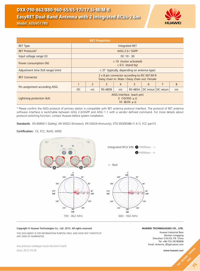
DXX-790-862/880-960-65/65-17i/17.5i-M/M-REasyRET Dual-Band Antenna with 2 Integrated RCUs-2.6mModel: ADU4517R0
RET Properties
RET Type Integrated RET
RET Protocols* AISG 2.0 / 3GPP
Input voltage range (V) DC 10 - 30
Power consumption (W) < 10 (motor activated)
< 0.5 (stand by)
Adjustment time (full range) (min) < 37 (typically, depending on antenna type)
RET Connector2 x 8 pin connector according to IEC 60130-9Daisy chain in: Male / Daisy chain out: Female
Pin assignment according AISG 1 2 3 4 5 6 7 8
DC n/c RS-485B n/c RS-485A DC in/out DC return n/c
Lightning protection (kA)AISG interface (each pin)
3 (10/350 μs)10 (8/20 μs)
* Please confirm the AISG protocol of primary station is compatible with RET antenna protocol interface. The protocol of RET antenna software interface is switchable between AISG 2.0/3GPP and AISG 1.1 with a vendor defined command. For more details about protocol switching function, contact Huawei before system installation.
Standards: EN 60950-1 (Safety), EN 55022 (Emission), EN 55024 (Immunity), ETSI EN300386 (1.4.1), FCC part15
Integrated RCU S/N: HWMxxx….r
HWMxxx…rr
r - Red
Certification: CE, FCC, RoHS, WEEE
Any previous catalogue issues become invalid.
Issue: 2012-10-26
HUAWEI TECHNOLOGIES CO., LTD.
Huawei Industrial BaseBantian Longgang
Shenzhen 518129, P.R. ChinaTel: +86-755-28780808
Email: [email protected]
www.huawei.com
Copyright © Huawei Technologies Co., Ltd. 2013. All rights reserved.
THIS DOCUMENT IS FOR INFORMATION PURPOSE ONLY, AND DOSE NOT CONSTITUTE ANY KIND OF WARRANTIES.
790 - 862 MHz 880 - 960 MHz
a
b
75790 - 8
62/8
80 - 96
0MHz
DXX

DXX-790-960/1710-2180-65/65-15i/17.5i-M/M
Model: ADU451503
Electrical Properties
Frequency range (MHz)790 - 960 1710 - 2180
790 - 862 824 - 894 880 - 960 1710 - 1880 1850 - 1990 1920 - 2180
Polarization +45° , -45°
Electrical downtilt (°) 0 - 14, continuously adjustable 0 - 10, continuously adjustable
Gain (dBi)0° 7° 14° 0° 7° 14° 0° 7° 14° 0° 5° 10° 0° 5° 10° 0° 5° 10°
14.6 14.5 14.3 15.0 14.7 14.5 15.1 15.0 14.5 16.7 16.8 16.6 17.0 17.3 16.6 17.5 17.6 16.7
Side lobe suppression for first side lobe above main beam (Typ.) (dB)
0° 7° 14° 0° 7° 14° 0° 7° 14° 0° 5° 10° 0° 5° 10° 0° 5° 10°
18 18 17 18 18 17 17 15 15 19 17 17 19 16 17 19 16 17
Horizontal 3dB beam width (°) 69 66 64 65 63 60
Vertical 3dB beam width (°) 15.7 15.0 14.0 7.5 7.1 6.6
VSWR < 1.5
Isolation between ports (dB)Intra-system: ≥ 30
Inter-system (790 - 960 // 1710 - 2180 MHz): ≥ 40
Front to back ratio, copolar (dB) Typ. 28 Typ. 28
Cross polar ratio (dB)0° Typ. 25 Typ. 20
±60° Typ. 10 Typ. 10
Max. power per input (W) 500 (at 50 ambient temperature) 300 (at 50 ambient temperature)
Intermodulation IM3 (dBc) ≤ -153 (2 x 43 dBm carrier)
Squint (°) Avg. 2.0
Tracking (dB) Avg. 2.0 (within 10dB HBW)
Impedance (Ω) 50
Grounding DC Ground
Mechanical Properties
Antenna dimensions (H x W x D) (mm) 1360 x 259 x 135
Antenna net weight (kg) 13.7
Bracket weight (kg) 4.6
Mechanical downtilt (°) 0 - 16
Mast diameter (mm) 50 - 115
Radome material Fiberglass
Radome colour Light grey
Operational temperature () -55 .. +65
Wind load (N) Frontal: 440 (at 150 km/h) Lateral: 230 (at 150 km/h)
Rear side: 585 (at 150 km/h)
Max. operational wind speed (km/h) 150
Survival wind speed (km/h) 200
Connector 4 x 7/16 DIN Female
Connector position Bottom
76
790 - 960/1710 - 2180MHz
DXX

790 - 960 MHz 1710 - 2180 MHz
790 - 960X
1710 - 2180X
+45° +45°
7/16 (F) 7/16 (F)7/16 (F) 7/16 (F)
-45° -45°
Unit: mm7055
56
HINT
Extraordinary operating conditions, such as heavy icing or storm wind, may result in the breakage of an antenna. These facts must be considered during the site planning process.
The installation team must be properly qualified and also be familiar with the relevant national safety regulations.
Any previous catalogue issues become invalid.
Issue: 2012-10-26
HUAWEI TECHNOLOGIES CO., LTD.
Huawei Industrial BaseBantian Longgang
Shenzhen 518129, P.R. ChinaTel: +86-755-28780808
Email: [email protected]
www.huawei.com
Copyright © Huawei Technologies Co., Ltd. 2013. All rights reserved.
THIS DOCUMENT IS FOR INFORMATION PURPOSE ONLY, AND DOSE NOT CONSTITUTE ANY KIND OF WARRANTIES.
DXX-790-960/1710-2180-65/65-15i/17.5i-M/M
Model: ADU451503
77790 - 9
60/1
710 - 2
180M
Hz
DXX

DXX-790-960/1710-2180-65/65-16.5i/18.5i-M/M
Model: ADU451602v01
Electrical Properties
Frequency range (MHz)790 - 960 1710 - 2180
790 - 862 824 - 894 880 - 960 1710 - 1880 1850 - 1990 1920 - 2180
Polarization +45° , -45°
Electrical downtilt (°) 0 - 12, continuously adjustable 0 - 8, continuously adjustable
Gain (dBi)0° 6° 12° 0° 6° 12° 0° 6° 12° 0° 4° 8° 0° 4° 8° 0° 4° 8°
15.7 15.7 15.3 16.0 16.0 15.5 16.2 16.0 15.6 18.0 18.5 18.3 18.2 18.7 18.3 18.3 18.7 18.3
Side lobe suppression for first side lobe above main beam (Typ.) (dB)
0° 6° 12° 0° 6° 12° 0° 6° 12° 0° 4° 8° 0° 4° 8° 0° 4° 8°
20 17 15 20 18 15 17 18 15 20 18 18 18 17 15 18 15 15
Horizontal 3dB beam width (°) 69 66 64 65 63 60
Vertical 3dB beam width (°) 10.6 10.2 9.5 5.2 5.0 4.7
VSWR < 1.5
Isolation between ports (dB)Intra-system: ≥ 30
Inter-system (790 - 960 // 1710 - 2180 MHz): ≥ 40
Front to back ratio, copolar (dB) Typ. 28 Typ. 30
Cross polar ratio (dB)0° Typ. 25 Typ. 20
±60° Typ. 10 Typ. 10
Max. power per input (W) 500 (at 50 ambient temperature) 300 (at 50 ambient temperature)
Intermodulation IM3 (dBc) ≤ -153 (2 x 43 dBm carrier)
Squint (°) Avg. 2.5
Tracking (dB) Avg. 2.0 (within 10dB HBW)
Impedance (Ω) 50
Grounding DC Ground
Mechanical Properties
Antenna dimensions (H x W x D) (mm) 1936 x 259 x 135
Antenna net weight (kg) 17.3
Bracket weight (kg) 4.6
Mechanical downtilt (°) 0 - 12
Mast diameter (mm) 50 - 115
Radome material Fiberglass
Radome colour Light grey
Operational temperature () -55 .. +65
Wind load (N)Frontal: 665 (at 150 km/h) Lateral: 345 (at 150 km/h)
Rear side: 880 (at 150 km/h)
Max. operational wind speed (km/h) 150
Survival wind speed (km/h) 200
Connector 4 x 7/16 DIN Female
Connector position Bottom
78
790 - 960/1710 - 2180MHz
DXX

790 - 960 MHz 1710 - 2180 MHz
Unit: mm7055
56
HINT
Extraordinary operating conditions, such as heavy icing or storm wind, may result in the breakage of an antenna. These facts must be considered during the site planning process.
The installation team must be properly qualified and also be familiar with the relevant national safety regulations.
Any previous catalogue issues become invalid.
Issue: 2012-10-26
HUAWEI TECHNOLOGIES CO., LTD.
Huawei Industrial BaseBantian Longgang
Shenzhen 518129, P.R. ChinaTel: +86-755-28780808
Email: [email protected]
www.huawei.com
Copyright © Huawei Technologies Co., Ltd. 2013. All rights reserved.
THIS DOCUMENT IS FOR INFORMATION PURPOSE ONLY, AND DOSE NOT CONSTITUTE ANY KIND OF WARRANTIES.
DXX-790-960/1710-2180-65/65-16.5i/18.5i-M/M
Model: ADU451602v01
790 - 960X
1710 - 2180X
+45° +45°
7/16 (F) 7/16 (F)7/16 (F) 7/16 (F)
-45° -45°
79790 - 9
60/1
710 - 2
180M
Hz
DXX

Electrical Properties
Frequency range (MHz)790 - 960 1710 - 2180
790 - 862 824 - 894 880 - 960 1710 - 1880 1850 - 1990 1920 - 2180
Polarization +45° , -45°
Electrical downtilt (°) 0 - 12 , continuously adjustable 0 - 8 , continuously adjustable
Gain (dBi)0° 6° 12° 0° 6° 12° 0° 6° 12° 0° 4° 8° 0° 4° 8° 0° 4° 8°
15.7 15.7 15.3 16.0 16.0 15.5 16.2 16.0 15.6 18.0 18.5 18.3 18.2 18.7 18.3 18.3 18.7 18.3
Side lobe suppression for first side lobe above main beam (Typ.) (dB)
0° 6° 12° 0° 6° 12° 0° 6° 12° 0° 4° 8° 0° 4° 8° 0° 4° 8°
20 17 15 20 18 15 17 18 15 20 18 18 18 17 15 18 15 15
Horizontal 3dB beam width (°) 69 66 64 65 63 60
Vertical 3dB beam width (°) 10.6 10.2 9.5 5.2 5.0 4.7
VSWR < 1.5
Isolation between ports (dB)Intra-system: ≥ 30
Inter-system (790 - 960 // 1710 - 2180 MHz): ≥ 40
Front to back ratio, copolar (dB) Typ. 28 Typ. 30
Cross polar ratio (dB)0° Typ. 25 Typ. 20
±60° Typ. 10 Typ. 10
Max. power per input (W) 500 (at 50 ambient temperature) 300 (at 50 ambient temperature)
Intermodulation IM3 (dBc) ≤ -153 (2 x 43 dBm carrier)
Squint (°) Avg. 2.5
Tracking (dB) Avg. 2.0 (within 10dB HBW)
Impedance (Ω) 50
Grounding DC Ground
DXX-790-960/1710-2180-65/65-16.5i/18.5i-M/M-REasyRET Dual-Band Antenna with 2 Integrated RCUs - 2.0mModel: ADU4518R3
Mechanical Properties
Antenna dimensions (H x W x D) (mm) 1936 x 259 x 135
Antenna net weight (kg) 18.3
Bracket weight (kg) 4.6
Mechanical downtilt (°) 0 - 12
Mast diameter (mm) 50 - 115
Radome material Fiberglass
Radome colour Light grey
Operational temperature () -40 .. +65
Wind load (N) Frontal: 665 (at 150 km/h) Lateral: 345 (at 150 km/h)
Rear side: 880 (at 150 km/h)
Max. operational wind speed (km/h) 150
Survival wind speed (km/h) 200
Connector 4 x 7/16 DIN Female
Connector position Bottom
80
790 - 960/1710 - 2180MHz
DXX

RET Properties
RET Type Integrated RET
RET Protocols AISG 2.0 / 3GPP
Input voltage range (V) DC 10 - 30
Power consumption (W) < 10 (motor activated)
< 0.5 (stand by)
Adjustment time (full range) (min) < 37 (typically, depending on antenna type)
RET Connector2 x 8 pin connector according to IEC 60130-9Daisy chain in: Male / Daisy chain out: Female
Pin assignment according AISG 1 2 3 4 5 6 7 8
DC n/c RS-485B n/c RS-485A DC in/out DC return n/c
Lightning protection (kA)AISG interface (each pin)
3 (10/350 μs)10 (8/20 μs)
Any previous catalogue issues become invalid.
Issue: 2012-10-26
HUAWEI TECHNOLOGIES CO., LTD.
Huawei Industrial BaseBantian Longgang
Shenzhen 518129, P.R. ChinaTel: +86-755-28780808
Email: [email protected]
www.huawei.com
Copyright © Huawei Technologies Co., Ltd. 2013. All rights reserved.
THIS DOCUMENT IS FOR INFORMATION PURPOSE ONLY, AND DOSE NOT CONSTITUTE ANY KIND OF WARRANTIES.
DXX-790-960/1710-2180-65/65-16.5i/18.5i-M/M-REasyRET Dual-Band Antenna with 2 Integrated RCUs - 2.0mModel: ADU4518R3
* Please confirm the AISG protocol of primary station is compatible with RET antenna protocol interface. The protocol of RET antenna software interface is switchable between AISG 2.0/3GPP and AISG 1.1 with a vendor defined command. For more details about protocol switching function, contact Huawei before system installation.
Standards: EN 60950-1 (Safety), EN 55022 (Emission), EN 55024 (Immunity), ETSI EN300386 (1.4.1), FCC part15
Integrated RCU S/N: HWMxxx…r
HWMxxx…b
Certification: CE, FCC, RoHS, WEEE
790 - 960 MHz 1710 - 2180 MHz
a
b
r - Red b - Blue
81790 - 9
60/1
710 - 2
180M
Hz
DXX

Electrical Properties
Frequency range (MHz)790 - 960 1710 - 2180
790 - 862 824 - 894 880 - 960 1710 - 1880 1850 - 1990 1920 - 2180
Polarization +45° , -45°
Electrical downtilt (°) 0 - 10, continuously adjustable 0 - 8, continuously adjustable
Gain (dBi)0° 5° 10° 0° 5° 10° 0° 5° 10° 0° 4° 8° 0° 4° 8° 0° 4° 8°
16.6 16.7 16.5 16.9 17.0 16.8 17.0 17.2 16.9 18.1 18.4 18.0 18.3 18.6 18.2 18.3 18.6 18.0
Side lobe suppression for first side lobe above main beam (Typ.) (dB)
0° 5° 10° 0° 5° 10° 0° 5° 10° 0° 4° 8° 0° 4° 8° 0° 4° 8°
19 19 18 19 19 18 19 18 17 18 16 18 20 16 18 20 16 18
Horizontal 3dB beam width (°) 69 66 65 64 62 60
Vertical 3dB beam width (°) 8.4 8.0 7.5 5.2 4.9 4.6
VSWR < 1.5
Isolation between ports (dB)Intra-system: ≥ 30Inter-system: ≥ 40
Front to back ratio, copolar (dB) Typ. 28 Typ. 29
Cross polar ratio (dB)0° Typ. 30 Typ. 20
±60° Typ. 10 Typ. 10
Max. power per input (W) 500 (at 50 ambient temperature) 300 (at 50 ambient temperature)
Intermodulation IM3 (dBc) ≤ -153 (2 x 43 dBm carrier)
Squint (°) Avg. 2.5
Tracking (dB) Avg. 1.0 (within 10dB HBW)
Impedance (Ω) 50
Grounding DC Ground
Mechanical Properties
Antenna dimensions (H x W x D) (mm) 2535 x 259 x 135
Antenna net weight (kg) 21
Bracket weight (kg) 5.6
Mechanical downtilt (°) 0 - 8
Mast diameter (mm) 50 - 115
Radome material Fiberglass
Radome colour Light grey
Operational temperature () -55 .. +65
Wind load (N) Frontal: 910 (at 150 km/h) Lateral: 470 (at 150 km/h)
Rear side: 1200 (at 150 km/h)
Max. operational wind speed (km/h) 150
Survival wind speed (km/h) 200
Connector 4 x 7/16 DIN Female
Connector position Bottom
DXX-790-960/1710-2180-65/65-17.5i/18.5i-M/M
Model: ADU451807v01
82
790 - 960/1710 - 2180MHz
DXX

790 - 960 MHz 1710 - 2180 MHz
DXX-790-960/1710-2180-65/65-17i/18.5i-M/M
Model: ADU451807v01
Unit: mm7055
56
HINT
Extraordinary operating conditions, such as heavy icing or storm wind, may result in the breakage of an antenna. These facts must be considered during the site planning process.
The installation team must be properly qualified and also be familiar with the relevant national safety regulations.
Any previous catalogue issues become invalid.
Issue: 2012-10-26
HUAWEI TECHNOLOGIES CO., LTD.
Huawei Industrial BaseBantian Longgang
Shenzhen 518129, P.R. ChinaTel: +86-755-28780808
Email: [email protected]
www.huawei.com
Copyright © Huawei Technologies Co., Ltd. 2013. All rights reserved.
THIS DOCUMENT IS FOR INFORMATION PURPOSE ONLY, AND DOSE NOT CONSTITUTE ANY KIND OF WARRANTIES.
790 - 960X
1710 - 2180X
+45° +45°
7/16 (F) 7/16 (F)7/16 (F) 7/16 (F)
-45° -45°
83790 - 9
60/1
710 - 2
180M
Hz
DXX

Electrical Properties
Frequency range (MHz)790 - 960 1710 - 2180
790 - 862 824 - 894 880 - 960 1710 - 1880 1850 - 1990 1920 - 2180
Polarization +45° , -45°
Electrical downtilt (°) 0 - 10 , continuously adjustable 0 - 8 , continuously adjustable
Gain (dBi)0° 5° 10° 0° 5° 10° 0° 5° 10° 0° 4° 8° 0° 4° 8° 0° 4° 8°
16.6 16.7 16.5 16.9 17.0 16.8 17.0 17.2 16.9 18.1 18.4 18.0 18.3 18.6 18.2 18.3 18.6 18.0
Side lobe suppression for first side lobe above main beam (Typ.) (dB)
0° 5° 10° 0° 5° 10° 0° 5° 10° 0° 4° 8° 0° 4° 8° 0° 4° 8°
19 19 18 19 19 18 19 18 17 18 16 18 20 16 18 20 16 18
Horizontal 3dB beam width (°) 69 66 65 64 62 60
Vertical 3dB beam width (°) 8.4 8.0 7.5 5.2 4.9 4.6
VSWR < 1.5
Isolation between ports (dB)Intra-system: ≥ 30
Inter-system (790 - 960 // 1710 - 2180 MHz): ≥ 40
Front to back ratio, copolar (dB) Typ. 28 Typ. 29
Cross polar ratio (dB)0° Typ. 30 Typ. 20
±60° Typ. 10 Typ. 10
Max. power per input (W) 500 (at 50 ambient temperature) 300 (at 50 ambient temperature)
Intermodulation IM3 (dBc) ≤ -153 (2 x 43 dBm carrier)
Squint (°) Avg. 2.5
Tracking (dB) Avg. 1.0 (within 10dB HBW)
Impedance (Ω) 50
Grounding DC Ground
DXX-790-960/1710-2180-65/65-17.5i/18.5i-M/M-REasyRET Dual-Band Antenna with 2 Integrated RCUs - 2.6mModel: ADU4518R0
Mechanical Properties
Antenna dimensions (H x W x D) (mm) 2535 x 259 x 135
Antenna net weight (kg) 22.2
Bracket weight (kg) 5.6
Mechanical downtilt (°) 0 - 8
Mast diameter (mm) 50 - 115
Radome material Fiberglass
Radome colour Light grey
Operational temperature () -40 .. +65
Wind load (N) Frontal: 910 (at 150 km/h) Lateral: 470 (at 150 km/h)
Rear side: 1200 (at 150 km/h)
Max. operational wind speed (km/h) 150
Survival wind speed (km/h) 200
Connector 4 x 7/16 DIN Female
Connector position Bottom
84
790 - 960/1710 - 2180MHz
DXX

Any previous catalogue issues become invalid.
Issue: 2012-10-26
HUAWEI TECHNOLOGIES CO., LTD.
Huawei Industrial BaseBantian Longgang
Shenzhen 518129, P.R. ChinaTel: +86-755-28780808
Email: [email protected]
www.huawei.com
Copyright © Huawei Technologies Co., Ltd. 2013. All rights reserved.
THIS DOCUMENT IS FOR INFORMATION PURPOSE ONLY, AND DOSE NOT CONSTITUTE ANY KIND OF WARRANTIES.
DXX-790-960/1710-2180-65/65-17.5i/18.5i-M/M-REasyRET Dual-Band Antenna with 2 Integrated RCUs - 2.6mModel: ADU4518R0
RET Properties
RET Type Integrated RET
RET Protocols AISG 2.0 / 3GPP
Input voltage range (V) DC 10 - 30
Power consumption (W) < 10 (motor activated)
< 0.5 (stand by)
Adjustment time (full range) (min) < 37 (typically, depending on antenna type)
RET Connector2 x 8 pin connector according to IEC 60130-9Daisy chain in: Male / Daisy chain out: Female
Pin assignment according AISG 1 2 3 4 5 6 7 8
DC n/c RS-485B n/c RS-485A DC in/out DC return n/c
Lightning protection (kA)AISG interface (each pin)
3 (10/350 μs)10 (8/20 μs)
* Please confirm the AISG protocol of primary station is compatible with RET antenna protocol interface. The protocol of RET antenna software interface is switchable between AISG 2.0/3GPP and AISG 1.1 with a vendor defined command. For more details about protocol switching function, contact Huawei before system installation.
Standards: EN 60950-1 (Safety), EN 55022 (Emission), EN 55024 (Immunity), ETSI EN300386 (1.4.1), FCC part15
Integrated RCU S/N: HWMxxx…r
HWMxxx…b
r - Red b - Blue
Certification: CE, FCC, RoHS, WEEE
790 - 960 MHz 1710 - 2180 MHz
a
b
85790 - 9
60/1
710 - 2
180M
Hz
DXX

Electrical Properties
Frequency range (MHz)790 - 960 1710 - 2180
790 - 862 824 - 894 880 - 960 1710 - 1880 1850 - 1990 1920 - 2180
Polarization +45° , -45°
Electrical downtilt (°) 0 - 14 , continuously adjustable 0 - 10 , continuously adjustable
Gain (dBi)0° 7° 14° 0° 7° 14° 0° 7° 14° 0° 5° 10° 0° 5° 10° 0° 5° 10°
14.6 14.5 14.3 15.0 14.7 14.5 15.1 15.0 14.5 16.7 16.8 16.6 17.0 17.3 16.6 17.5 17.6 16.7
Side lobe suppression for first side lobe above main beam (Typ.) (dB)
0° 7° 14° 0° 7° 14° 0° 7° 14° 0° 5° 10° 0° 5° 10° 0° 5° 10°
18 18 17 18 18 17 17 15 15 19 17 17 19 16 17 19 16 17
Horizontal 3dB beam width (°) 69 66 64 65 63 60
Vertical 3dB beam width (°) 15.7 15.0 14.0 7.5 7.1 6.6
VSWR < 1.5
Isolation between ports (dB) Intra-system: ≥ 30
Front to back ratio, copolar (dB) Typ. 28 Typ. 28
Cross polar ratio (dB)0° Typ. 25 Typ. 20
±60° Typ. 10 Typ. 10
Max. power per input (W) 250 (at 50 ambient temperature) 200 (at 50 ambient temperature)
Total power per combined input (W) 450 (at 50 ambient temperature)
Intermodulation IM3 (dBc) ≤ -153 (2 x 43 dBm carrier)
Squint (°) Avg. 2.0
Tracking (dB) Avg. 2.0 (within 10dB HBW)
Impedance (Ω) 50
Grounding DC Ground
Mechanical Properties
Antenna dimensions (H x W x D) (mm) 1360 x 259 x 135
Antenna net weight (kg) 13.7
Bracket weight (kg) 4.6
Mechanical downtilt (°) 0 - 16
Mast diameter (mm) 50 - 115
Radome material Fiberglass
Radome colour Light grey
Operational temperature () -55 .. +65
Wind load (N)Frontal: 440 (at 150 km/h)Lateral: 230 (at 150 km/h)
Rear side: 585 (at 150 km/h)
Max. operational wind speed (km/h) 150
Survival wind speed (km/h) 200
Connector 2 x 7/16 DIN Female
Connector position Bottom
Any previous catalogue issues become invalid.
Issue: 2013-01-08
HUAWEI TECHNOLOGIES CO., LTD.
Huawei Industrial BaseBantian Longgang
Shenzhen 518129, P.R. ChinaTel: +86-755-28780808
Email: [email protected]
www.huawei.com
Copyright © Huawei Technologies Co., Ltd. 2013. All rights reserved.
THIS DOCUMENT IS FOR INFORMATION PURPOSE ONLY, AND DOSE NOT CONSTITUTE ANY KIND OF WARRANTIES.
DXX-790-960/1710-2180-65/65-15i/17.5i-M/M-C
Model: ADU4517C0
Preliminary Issue
86
790 - 960/1710 - 2180MHz
DXX

Electrical Properties
Frequency range (MHz)790 - 960 1710 - 2180
790 - 862 824 - 894 880 - 960 1710 - 1880 1850 - 1990 1920 - 2180
Polarization +45° , -45°
Electrical downtilt (°) 0 - 12 , continuously adjustable 0 - 8 , continuously adjustable
Gain (dBi)0° 6° 12° 0° 6° 12° 0° 6° 12° 0° 4° 8° 0° 4° 8° 0° 4° 8°
15.7 15.7 15.3 16.0 16.0 15.5 16.2 16.0 15.6 18.0 18.5 18.3 18.2 18.7 18.3 18.3 18.7 18.3
Side lobe suppression for first side lobe above main beam (Typ.) (dB)
0° 6° 12° 0° 6° 12° 0° 6° 12° 0° 4° 8° 0° 4° 8° 0° 4° 8°
20 17 15 20 18 15 17 18 15 20 18 18 18 17 15 18 15 15
Horizontal 3dB beam width (°) 69 66 64 65 63 60
Vertical 3dB beam width (°) 10.6 10.2 9.5 5.2 5.0 4.7
VSWR < 1.5
Isolation between ports (dB) Intra-system: ≥ 30
Front to back ratio, copolar (dB) Typ. 28 Typ. 30
Cross polar ratio (dB)0° Typ. 25 Typ. 20
±60° Typ. 10 Typ. 10
Max. power per input (W) 250 (at 50 ambient temperature) 200 (at 50 ambient temperature)
Total power per combined input (W) 450 (at 50 ambient temperature)
Intermodulation IM3 (dBc) ≤ -153 (2 x 43 dBm carrier)
Squint (°) Avg. 2.5
Tracking (dB) Avg. 2.0 (within 10dB HBW)
Impedance (Ω) 50
Grounding DC Ground
Mechanical Properties
Antenna dimensions (H x W x D) (mm) 1936 x 259 x 135
Antenna net weight (kg) 17.3
Bracket weight (kg) 4.6
Mechanical downtilt (°) 0 - 12
Mast diameter (mm) 50 - 115
Radome material Fiberglass
Radome colour Light grey
Operational temperature () -55 .. +65
Wind load (N)Frontal: 665 (at 150 km/h)Lateral: 345 (at 150 km/h)
Rear side: 880 (at 150 km/h)
Max. operational wind speed (km/h) 150
Survival wind speed (km/h) 200
Connector 2 x 7/16 DIN Female
Connector position Bottom
Any previous catalogue issues become invalid.
Issue: 2013-01-08
HUAWEI TECHNOLOGIES CO., LTD.
Huawei Industrial BaseBantian Longgang
Shenzhen 518129, P.R. ChinaTel: +86-755-28780808
Email: [email protected]
www.huawei.com
Copyright © Huawei Technologies Co., Ltd. 2013. All rights reserved.
THIS DOCUMENT IS FOR INFORMATION PURPOSE ONLY, AND DOSE NOT CONSTITUTE ANY KIND OF WARRANTIES.
DXX-790-960/1710-2180-65/65-16.5i/18.5i-M/M-C
Model: ADU4518C1
Preliminary Issue
87790 - 9
60/1
710 - 2
180M
Hz
DXX

DXX-790-960/1710-2180-65/65-17i/18.5i-M/M-C
Model: ADU4518C0
Electrical Properties
Frequency range (MHz)790 - 960 1710 - 2180
790 - 862 824 - 894 880 - 960 1710 - 1880 1850 - 1990 1920 - 2180
Polarization +45° , -45°
Electrical downtilt (°) 0 - 10, continuously adjustable 0 - 8, continuously adjustable
Gain (dBi)0° 5° 10° 0° 5° 10° 0° 5° 10° 0° 4° 8° 0° 4° 8° 0° 4° 8°
16.6 16.7 16.5 16.9 17.0 16.8 17.0 17.2 16.9 18.1 18.4 18.0 18.3 18.6 18.2 18.3 18.6 18.0
Side lobe suppression for first side lobe above main beam (Typ.) (dB)
0° 5° 10° 0° 5° 10° 0° 5° 10° 0° 4° 8° 0° 4° 8° 0° 4° 8°
19 19 18 19 19 18 19 18 17 18 16 18 20 16 18 20 16 18
Horizontal 3dB beam width (°) 69 66 65 64 62 60
Vertical 3dB beam width (°) 8.4 8.0 7.5 5.2 4.9 4.6
VSWR < 1.5
Isolation between ports (dB) Intra-system: ≥ 30
Front to back ratio, copolar (dB) Typ. 28 Typ. 29
Cross polar ratio (dB)0° Typ. 30 Typ. 20
±60° Typ. 10 Typ. 10
Max. power per input (W) 250 (at 50 ambient temperature) 200 (at 50 ambient temperature)
Total power per combined input (W) 450 (at 50 ambient temperature)
Intermodulation IM3 (dBc) ≤ -153 (2 x 43 dBm carrier)
Squint (°) Avg. 2.5
Tracking (dB) Avg. 1.0 (within 10dB HBW)
Impedance (Ω) 50
Grounding DC Ground
Mechanical Properties
Antenna dimensions (H x W x D) (mm) 2535 x 259 x 135
Antenna net weight (kg) 20.8
Bracket weight (kg) 5.6
Mechanical downtilt (°) 0 - 8
Mast diameter (mm) 50 - 115
Radome material Fiberglass
Radome colour Light grey
Operational temperature () -55 .. +65
Wind load (N)Frontal: 910 (at 150 km/h)Lateral: 470 (at 150 km/h)
Rear side: 1200 (at 150 km/h)
Max. operational wind speed (km/h) 150
Survival wind speed (km/h) 200
Connector 2 x 7/16 DIN Female
Connector position Bottom
88
790 - 960/1710 - 2180MHz
DXX

790 - 960 MHz 1710 - 2180 MHz
790 - 960X
1710 - 2180X
7/16 (F)7/16 (F)
+45° +45°-45° -45°
CC
Unit: mm7070
54
HINT
Extraordinary operating conditions, such as heavy icing or storm wind, may result in the breakage of an antenna. These facts must be considered during the site planning process.
The installation team must be properly qualified and also be familiar with the relevant national safety regulations.
Any previous catalogue issues become invalid.
Issue: 2012-10-26
HUAWEI TECHNOLOGIES CO., LTD.
Huawei Industrial BaseBantian Longgang
Shenzhen 518129, P.R. ChinaTel: +86-755-28780808
Email: [email protected]
www.huawei.com
Copyright © Huawei Technologies Co., Ltd. 2013. All rights reserved.
THIS DOCUMENT IS FOR INFORMATION PURPOSE ONLY, AND DOSE NOT CONSTITUTE ANY KIND OF WARRANTIES.
DXX-790-960/1710-2180-65/65-17i/18.5i-M/M-C
Model: ADU4518C0
89790 - 9
60/1
710 - 2
180M
Hz
DXX

Electrical Properties
Frequency range (MHz)790 - 960 1710 - 2180
790 - 862 824 - 894 880 - 960 1710 - 1880 1850 - 1990 1920 - 2180
Polarization +45° , -45°
Electrical downtilt (°) 0 - 12, continuously adjustable 0 - 8, continuously adjustable
Gain (dBi)0° 6° 12° 0° 6° 12° 0° 6° 12° 0° 4° 8° 0° 4° 8° 0° 4° 8°
15.7 15.7 15.3 16.0 16.0 15.5 16.2 16.0 15.6 18.0 18.3 18.1 18.2 18.5 18.1 18.3 18.5 18.1
Side lobe suppression (Typ.) (dB)
-for first side lobe above main beam
-within 0° - 15° sector above horizon
0° 6° 12° 0° 6° 12° 0° 6° 12° 0° 4° 8° 0° 4° 8° 0° 4° 8°
20 17 15 20 18 15 17 18 15 20 18 18 18 17 15 18 15 15
15 16 15 15 16 15 15 16 15 16 16 15 16 16 15 16 16 15
Horizontal 3dB beam width (°) 69 66 64 65 63 60
Vertical 3dB beam width (°) 10.6 10.2 9.5 5.2 5.0 4.7
VSWR < 1.5
Isolation between ports (dB)Intra-system: ≥ 30
Inter-system (790 - 960 // 1710 - 2180 MHz): ≥ 40
Front to back ratio, copolar (dB) Typ. 28 Typ. 30
Cross polar ratio (dB)0° Typ. 25 Typ. 20
±60° Typ. 10 Typ. 10
Max. power per input (W) 500 (at 50 ambient temperature) 300 (at 50 ambient temperature)
Intermodulation IM3 (dBc) ≤ -153 (2 x 43 dBm carrier)
Squint (°) Avg. 2.5
Tracking (dB) Avg. 2.0 (within 10dB HBW)
Impedance (Ω) 50
Grounding DC Ground
Mechanical Properties
Antenna dimensions (H x W x D) (mm) 1936 x 259 x 135
Antenna net weight (kg) 18.1
Bracket weight (kg) 4.6
Mechanical downtilt (°) 0 - 12
Mast diameter (mm) 50 - 115
Radome material Fiberglass
Radome colour Light grey
Operational temperature () -55 .. +65
Wind load (N) Frontal: 665 (at 150 km/h) Lateral: 345 (at 150 km/h)
Rear side: 880 (at 150 km/h)
Max. operational wind speed (km/h) 150
Survival wind speed (km/h) 200
Connector 4 x 7/16 DIN Female
Connector position Bottom
DXX-790-960/1710-2180-65/65-16.5i/18.5i-M/M-ESLS
Model: ADU451820
90
790 - 960/1710 - 2180MHz
DXX
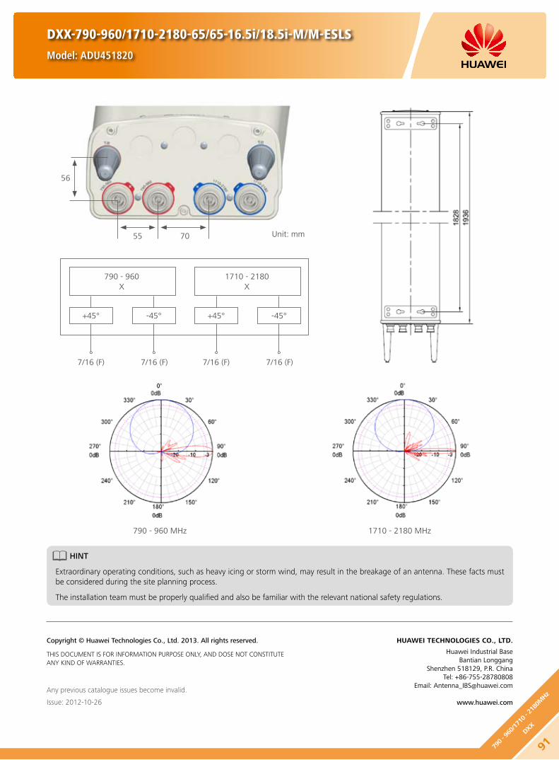
790 - 960 MHz 1710 - 2180 MHz
DXX-790-960/1710-2180-65/65-16.5i/18.5i-M/M-ESLS
Model: ADU451820
Unit: mm7055
56
HINT
Extraordinary operating conditions, such as heavy icing or storm wind, may result in the breakage of an antenna. These facts must be considered during the site planning process.
The installation team must be properly qualified and also be familiar with the relevant national safety regulations.
Any previous catalogue issues become invalid.
Issue: 2012-10-26
HUAWEI TECHNOLOGIES CO., LTD.
Huawei Industrial BaseBantian Longgang
Shenzhen 518129, P.R. ChinaTel: +86-755-28780808
Email: [email protected]
www.huawei.com
Copyright © Huawei Technologies Co., Ltd. 2013. All rights reserved.
THIS DOCUMENT IS FOR INFORMATION PURPOSE ONLY, AND DOSE NOT CONSTITUTE ANY KIND OF WARRANTIES.
790 - 960X
1710 - 2180X
+45° +45°
7/16 (F) 7/16 (F)7/16 (F) 7/16 (F)
-45° -45°
91790 - 9
60/1
710 - 2
180M
Hz
DXX

Electrical Properties
Frequency range (MHz)790 - 960 1710 - 2180
790 - 862 824 - 894 880 - 960 1710 - 1880 1850 - 1990 1920 - 2180
Polarization +45° , -45°
Electrical downtilt (°) 0 - 10, continuously adjustable 0 - 8, continuously adjustable
Gain (dBi)0° 5° 10° 0° 5° 10° 0° 5° 10° 0° 4° 8° 0° 4° 8° 0° 4° 8°
16.6 16.7 16.5 16.9 17.0 16.8 17.0 17.2 16.9 18.1 18.4 18.0 18.3 18.5 18.2 18.3 18.5 18.0
Side lobe suppression (Typ.) (dB)
-for first side lobe above main beam
-within 0° - 15° sector above horizon
0° 5° 10° 0° 5° 10° 0° 5° 10° 0° 4° 8° 0° 4° 8° 0° 4° 8°
19 19 18 19 19 18 19 18 17 18 16 18 20 16 18 20 16 18
15 16 15 15 16 15 15 16 15 16 16 15 16 16 15 16 16 15
Horizontal 3dB beam width (°) 69 66 65 64 62 60
Vertical 3dB beam width (°) 8.4 8.0 7.5 5.2 4.9 4.6
VSWR < 1.5
Isolation between ports (dB)Intra-system: ≥ 30
Inter-system (790 - 960 // 1710 - 2180 MHz): ≥ 40
Front to back ratio, copolar (dB) Typ. 28 Typ. 29
Cross polar ratio (dB)0° Typ. 30 Typ. 20
±60° Typ. 10 Typ. 10
Max. power per input (W) 500 (at 50 ambient temperature) 300 (at 50 ambient temperature)
Intermodulation IM3 (dBc) ≤ -153 (2 x 43 dBm carrier)
Squint (°) Avg. 2.5
Tracking (dB) Avg. 1.0 (within 10dB HBW)
Impedance (Ω) 50
Grounding DC Ground
Mechanical Properties
Antenna dimensions (H x W x D) (mm) 2535 x 259 x 135
Antenna net weight (kg) 21.6
Bracket weight (kg) 5.6
Mechanical downtilt (°) 0 - 8
Mast diameter (mm) 50 - 115
Radome material Fiberglass
Radome colour Light grey
Operational temperature () -55 .. +65
Wind load (N) Frontal: 910 (at 150 km/h) Lateral: 470 (at 150 km/h)
Rear side: 1200 (at 150 km/h)
Max. operational wind speed (km/h) 150
Survival wind speed (km/h) 200
Connector 4 x 7/16 DIN Female
Connector position Bottom
DXX-790-960/1710-2180-65/65-17.5i/18.5i-M/M-ESLS
Model: ADU451821
92
790 - 960/1710 - 2180MHz
DXX

790 - 960 MHz 1710 - 2180 MHz
DXX-790-960/1710-2180-65/65-17.5i/18.5i-M/M-ESLS
Model: ADU451821
Unit: mm7055
56
HINT
Extraordinary operating conditions, such as heavy icing or storm wind, may result in the breakage of an antenna. These facts must be considered during the site planning process.
The installation team must be properly qualified and also be familiar with the relevant national safety regulations.
Any previous catalogue issues become invalid.
Issue: 2012-10-26
HUAWEI TECHNOLOGIES CO., LTD.
Huawei Industrial BaseBantian Longgang
Shenzhen 518129, P.R. ChinaTel: +86-755-28780808
Email: [email protected]
www.huawei.com
Copyright © Huawei Technologies Co., Ltd. 2013. All rights reserved.
THIS DOCUMENT IS FOR INFORMATION PURPOSE ONLY, AND DOSE NOT CONSTITUTE ANY KIND OF WARRANTIES.
790 - 960X
1710 - 2180X
+45° +45°
7/16 (F) 7/16 (F)7/16 (F) 7/16 (F)
-45° -45°
93790 - 9
60/1
710 - 2
180M
Hz
DXX

Electrical Properties
Frequency range (MHz)790 - 960 1710 - 2690
790 - 862 824 - 894 880 - 960 1710 - 1880 1850 - 1990 1920 - 2180
Polarization +45° , -45°
Electrical downtilt (°) 0 - 14 , continuously adjustable 0 - 10 , continuously adjustable
Gain (dBi)0° 7° 14° 0° 7° 14° 0° 7° 14° 0° 5° 10° 0° 5° 10° 0° 5° 10°
14.5 14.3 14 14.7 14.5 14.1 15.0 14.9 14.4 16.6 16.8 16.2 16.9 17.0 16.2 17.0 17.2 16.5
Side lobe suppression for first side lobe above main beam (Typ.) (dB)
0° 7° 14° 0° 7° 14° 0° 7° 14° 0° 5° 10° 0° 5° 10° 0° 5° 10°
16 15 15 16 15 15 16 15 15 16 16 15 16 16 15 16 16 15
Horizontal 3dB beam width (°) 69 66 64 64 62 60
Vertical 3dB beam width (°) 16.6 15.5 14.4 6.8 6.4 5.9
VSWR < 1.5
Isolation between ports (dB)Intra-system: ≥ 28Inter-system: ≥ 40
Front to back ratio, copolar (dB) Typ. 27 Typ. 28
Cross polar ratio (dB)0° Typ. 20 Typ. 20
±60° Typ. 10 Typ. 10
Max. power per input (W) 500 (at 50 ambient temperature) 250 (at 50 ambient temperature)
Intermodulation IM3 (dBc) ≤ -153 (2 x 43 dBm carrier)
Impedance (Ω) 50
Grounding DC Ground
Mechanical Properties
Antenna dimensions (H x W x D) (mm) 1450 x 298 x 148
Antenna net weight (kg) 17
Bracket weight (kg) 4.6
Mechanical downtilt (°) 0 - 14
Mast diameter (mm) 50 - 115
Radome material Fiberglass
Radome colour Light grey
Operational temperature () -55 .. +65
Wind load (N)Frontal: 375 (at 150 km/h) Lateral: 170 (at 150 km/h)
Rear side: 595 (at 150 km/h)
Max. operational wind speed (km/h) 150
Survival wind speed (km/h) 200
Connector 4 x 7/16 DIN Female
Connector position Bottom
Any previous catalogue issues become invalid.
Issue: 2013-01-08
HUAWEI TECHNOLOGIES CO., LTD.
Huawei Industrial BaseBantian Longgang
Shenzhen 518129, P.R. ChinaTel: +86-755-28780808
Email: [email protected]
www.huawei.com
Copyright © Huawei Technologies Co., Ltd. 2013. All rights reserved.
THIS DOCUMENT IS FOR INFORMATION PURPOSE ONLY, AND DOSE NOT CONSTITUTE ANY KIND OF WARRANTIES.
DXX-790-960/1710-2690-65/65-15i/17.5i-M/M
Model: ADU451716
Preliminary Issue
94
790 - 960/1710 - 2690MHz
DXX

Electrical Properties
Frequency range (MHz)790 - 960 1710 - 2690
790 - 862 824 - 894 880 - 960 1710 - 1880 1850 - 1990 1920 - 2170 2490 - 2690
Polarization +45° , -45°
Electrical downtilt (°) 0 - 10, continuously adjustable 0 - 8, continuously adjustable
Gain (dBi)0° 5° 10° 0° 5° 10° 0° 5° 10° 0° 4° 8° 0° 4° 8° 0° 4° 8° 0° 4° 8°
16.0 16.0 15.5 16.1 16.1 15.6 16.2 16.2 15.7 17.9 18.0 17.7 18.2 18.3 18.1 18.4 18.5 18.2 18.4 18.5 18.2
Side lobe suppression (Typ.) (dB)
-for first side lobe above main beam
-within 0° - 15° sector above horizon
0° 5° 10° 0° 5° 10° 0° 5° 10° 0° 4° 8° 0° 4° 8° 0° 4° 8° 0° 4° 8°
18 18 18 18 18 18 18 18 18 18 18 17 18 17 17 18 17 17 18 18 17
16 16 15 16 16 15 16 16 15 15 16 15 15 16 15 15 16 15 15 15 15
Horizontal 3dB beam width (°) 66 64 63 64 62 60 61
Vertical 3dB beam width (°) 9.8 9.5 8.9 5.4 5.1 4.9 3.9
VSWR < 1.5
Isolation between ports (dB)Intra-system: ≥ 30 Intra-system: ≥ 28
Inter-system (790 - 960 // 1710 - 2690 MHz): ≥ 30
Front to back ratio, copolar (dB) Typ. 28 Typ. 30
Cross polar ratio (dB)0° Typ. 20 Typ. 20 Typ. 20
±60° Typ. 10 Typ. 10 Typ. 8
Max. power per input (W) 500 (at 50 ambient temperature) 250 (at 50 ambient temperature)
Intermodulation IM3 (dBc) ≤ -153 (2 x 43 dBm carrier)
Squint (°) Typ. 2.5
Tracking (dB) Avg. 1.5 (within 10dB HBW)
Impedance (Ω) 50
Grounding DC Ground
Mechanical Properties
Antenna dimensions (H x W x D) (mm) 2020 x 298 x 150
Antenna net weight (kg) 21.2
Bracket weight (kg) 5.6
Mechanical downtilt (°) 0 - 12
Mast diameter (mm) 50 - 115
Radome material Fiberglass
Radome colour Light grey
Operational temperature () -55 .. +65
Wind load (N)Frontal: 825 (at 150 km/h)Lateral: 355 (at 150 km/h)
Rear side: 990 (at 150 km/h)
Max. operational wind speed (km/h) 150
Survival wind speed (km/h) 200
Connector 4 x 7/16 DIN Female
Connector position Bottom
DXX-790-960/1710-2690-65/65-16i/18.5i-M/M
Model: ADU451604
95790 - 9
60/1
710 - 2
690M
Hz
DXX

790 - 960 MHz 1710 - 2690 MHz
790 - 960X
1710 - 2690X
+45° +45°
7/16 (F) 7/16 (F)7/16 (F) 7/16 (F)
-45° -45°
DXX-790-960/1710-2690-65/65-16i/18.5i-M/M
Model: ADU451604
Unit: mm11259
60
HINT
Extraordinary operating conditions, such as heavy icing or storm wind, may result in the breakage of an antenna. These facts must be considered during the site planning process.
The installation team must be properly qualified and also be familiar with the relevant national safety regulations.
Any previous catalogue issues become invalid.
Issue: 2012-10-26
HUAWEI TECHNOLOGIES CO., LTD.
Huawei Industrial BaseBantian Longgang
Shenzhen 518129, P.R. ChinaTel: +86-755-28780808
Email: [email protected]
www.huawei.com
Copyright © Huawei Technologies Co., Ltd. 2013. All rights reserved.
THIS DOCUMENT IS FOR INFORMATION PURPOSE ONLY, AND DOSE NOT CONSTITUTE ANY KIND OF WARRANTIES.
96
790 - 960/1710 - 2690MHz
DXX

Electrical Properties
Frequency range (MHz)790 - 960 1710 - 2690
790 - 862 824 - 894 880 - 960 1710 - 1880 1850 - 1990 1920 - 2170 2490 - 2690
Polarization +45° , -45°
Electrical downtilt (°) 0 - 10, continuously adjustable 0 - 8, continuously adjustable
Gain (dBi)0° 5° 10° 0° 5° 10° 0° 5° 10° 0° 4° 8° 0° 4° 8° 0° 4° 8° 0° 4° 8°
16.6 16.8 16.1 16.7 16.9 16.5 16.6 17.0 16.8 17.9 18.0 17.7 18.2 18.3 18.1 18.4 18.5 18.2 18.4 18.5 18.2
Side lobe suppression (Typ.) (dB)
-for first side lobe above main beam
-within 0° - 15° sector above horizon
0° 5° 10° 0° 5° 10° 0° 5° 10° 0° 4° 8° 0° 4° 8° 0° 4° 8° 0° 4° 8°
18 18 18 18 18 18 18 18 18 18 18 17 18 17 17 18 17 17 18 18 17
16 16 15 16 16 15 16 16 15 15 16 15 15 16 15 15 16 15 15 15 15
Horizontal 3dB beam width (°) 67 65 64 64 62 60 61
Vertical 3dB beam width (°) 8.5 8.2 7.7 5.4 5.1 4.9 3.9
VSWR < 1.5
Isolation between ports (dB)Intra-system: ≥ 30 Intra-system: ≥ 28
Inter-system (790 - 960 // 1710 - 2690 MHz): ≥ 30
Front to back ratio, copolar (dB) Typ. 28 Typ. 30
Cross polar ratio (dB)0° Typ. 20 Typ. 20 Typ. 20
±60° Typ. 10 Typ. 10 Typ. 8
Max. power per input (W) 500 (at 50 ambient temperature) 250 (at 50 ambient temperature)
Intermodulation IM3 (dBc) ≤ -153 (2 x 43 dBm carrier)
Squint (°) Typ. 2.5
Tracking (dB) Avg. 1.5 (within 10dB HBW)
Impedance (Ω) 50
Grounding DC Ground
Mechanical Properties
Antenna dimensions (H x W x D) (mm) 2520 x 298 x 150
Antenna net weight (kg) 24.5
Bracket weight (kg) 5.6
Mechanical downtilt (°) 0 - 12
Mast diameter (mm) 50 - 115
Radome material Fiberglass
Radome colour Light grey
Operational temperature () -55 .. +65
Wind load (N)Frontal: 1060 (at 150 km/h)Lateral: 455 (at 150 km/h)
Rear side: 1275 (at 150 km/h)
Max. operational wind speed (km/h) 150
Survival wind speed (km/h) 200
Connector 4 x 7/16 DIN Female
Connector position Bottom
DXX-790-960/1710-2690-65/65-17i/18.5i-M/M
Model: ADU451712
Preliminary Issue
97790 - 9
60/1
710 - 2
690M
Hz
DXX

Preliminary Issue
HINT
Extraordinary operating conditions, such as heavy icing or storm wind, may result in the breakage of an antenna. These facts must be considered during the site planning process.
The installation team must be properly qualified and also be familiar with the relevant national safety regulations.
Any previous catalogue issues become invalid.
Issue: 2013-01-08
HUAWEI TECHNOLOGIES CO., LTD.
Huawei Industrial BaseBantian Longgang
Shenzhen 518129, P.R. ChinaTel: +86-755-28780808
Email: [email protected]
www.huawei.com
Copyright © Huawei Technologies Co., Ltd. 2013. All rights reserved.
THIS DOCUMENT IS FOR INFORMATION PURPOSE ONLY, AND DOSE NOT CONSTITUTE ANY KIND OF WARRANTIES.
DXX-790-960/1710-2690-65/65-17i/18.5i-M/M
Model: ADU451712
98
790 - 960/1710 - 2690MHz
DXX
790 - 960 MHz 1710 - 2690 MHz
790 - 960X
1710 - 2690X
+45°+45°
7/16 (F) 7/16 (F)7/16 (F) 7/16 (F)
-45°-45°
Unit: mm11259
60

DXX-1710-2200/1710-2200-65/65-15.5i/15.5i-M/M
Model: ADU451611
Preliminary Issue
Electrical Properties
Frequency range (MHz)2 x (1710 - 2200)
1710 - 1880 1850 - 1990 1920 - 2170 2170 - 2200
Polarization +45° , -45°
Electrical downtilt (°) 0 - 12 , continuously adjustable
Gain (dBi)0° 6° 12° 0° 6° 12° 0° 6° 12° 0° 6° 12°
15.2 15.2 15.0 15.4 15.3 15.0 15.5 15.4 15.2 15.5 15.4 15.0
Side lobe suppression for first side lobe above main beam (Typ.) (dB)
0° 6° 12° 0° 6° 12° 0° 6° 12° 0° 6° 12°
17 16 15 17 16 15 17 16 15 16 15 15
Horizontal 3dB beam width (°) 67 64 61 60
Vertical 3dB beam width (°) 13.9 13.0 12.6 11.5
VSWR < 1.5
Isolation between ports (dB) ≥ 30
Front to back ratio, copolar (dB) Typ. 28
Cross polar ratio (dB)0° Typ. 22
±60° Typ. 10
Max. power per input (W) 300 (at 50 ambient temperature)
Intermodulation IM3 (dBc) ≤ -150 (2 x 43 dBm carrier)
Squint (°) Avg.2.0
Tracking (dB) Avg.2.0 (within 10dB HBW)
Impedance (Ω) 50
Grounding DC Ground
Mechanical Properties
Antenna dimensions (H x W x D) (mm) 701 x 323 x 89
Antenna net weight (kg) 9
Bracket weight (kg) 4.6
Mechanical downtilt (°) 0 - 20
Mast diameter (mm) 50 - 115
Radome material Fiberglass
Radome colour Light grey
Operational temperature () -55 .. +65
Wind load (N)Frontal: 285 (at 150 km/h)Lateral: 50 (at 150 km/h)
Rear side: 320 (at 150 km/h)
Max. operational wind speed (km/h) 150
Survival wind speed (km/h) 200
Connector 4 x 7/16 DIN Female
Connector position Bottom
Any previous catalogue issues become invalid.
Issue: 2013-01-08
HUAWEI TECHNOLOGIES CO., LTD.
Huawei Industrial BaseBantian Longgang
Shenzhen 518129, P.R. ChinaTel: +86-755-28780808
Email: [email protected]
www.huawei.com
Copyright © Huawei Technologies Co., Ltd. 2013. All rights reserved.
THIS DOCUMENT IS FOR INFORMATION PURPOSE ONLY, AND DOSE NOT CONSTITUTE ANY KIND OF WARRANTIES.
991710
- 22
00/1
710 - 2
200M
Hz
DXX

Electrical Properties
Frequency range (MHz)2 x (1710 - 2200)
1710 - 1880 1850 - 1990 1920 - 2170 2170 - 2200
Polarization +45° , -45°
Electrical downtilt (°) 0 - 10, continuously adjustable
Gain (dBi)0° 5° 10° 0° 5° 10° 0° 5° 10° 0° 5° 10°
17.0 17.4 17.1 17.3 17.7 17.4 17.6 18.0 17.4 17.5 18.0 17.4
Side lobe suppression for first side lobe above main beam (Typ.) (dB)
0° 5° 10° 0° 5° 10° 0° 5° 10° 0° 5° 10°
18 17 17 19 18 18 19 18 17 19 18 17
Horizontal 3dB beam width (°) 67 64 61 60
Vertical 3dB beam width (°) 7.5 7.0 6.6 6.2
VSWR < 1.5
Isolation between ports (dB) ≥ 30
Front to back ratio, copolar (dB) Typ. 28
Cross polar ratio (dB)0° Typ. 22
±60° Typ. 10
Max. power per input (W) 300 (at 50 ambient temperature)
Intermodulation IM3 (dBc) ≤ -153 (2 x 43 dBm carrier)
Squint (°) Avg. 2
Tracking (dB) Avg. 1.5 (within 10dB HBW)
Impedance (Ω) 50
Grounding DC Ground
Mechanical Properties
Antenna dimensions (H x W x D) (mm) 1311 x 323 x 89
Antenna net weight (kg) 12.8
Bracket weight (kg) 4.6
Mechanical downtilt (°) 0 - 16
Mast diameter (mm) 50 - 115
Radome material Fiberglass
Radome colour Light grey
Operational temperature () -55 .. +65
Wind load (N)Frontal: 565 (at 150 km/h)Lateral: 105 (at 150 km/h)
Rear side: 640 (at 150 km/h)
Max. operational wind speed (km/h) 150
Survival wind speed (km/h) 200
Connector 4 x 7/16 DIN Female
Connector position Bottom
DXX-1710-2200/1710-2200-65/65-18i/18i-M/M
Model: ADU451819
100
1710 - 2200/1710 - 2200MHz
DXX

1710 - 2200 MHz
1710 - 2200X
1710 - 2200X
+45° +45°
7/16 (F) 7/16 (F)7/16 (F) 7/16 (F)
-45° -45°
DXX-1710-2200/1710-2200-65/65-18i/18i-M/M
Model: ADU451819
Unit: mmL - Left Column R - Right Column
593643
31
HINT
Extraordinary operating conditions, such as heavy icing or storm wind, may result in the breakage of an antenna. These facts must be considered during the site planning process.
The installation team must be properly qualified and also be familiar with the relevant national safety regulations.
Any previous catalogue issues become invalid.
Issue: 2012-10-26
HUAWEI TECHNOLOGIES CO., LTD.
Huawei Industrial BaseBantian Longgang
Shenzhen 518129, P.R. ChinaTel: +86-755-28780808
Email: [email protected]
www.huawei.com
Copyright © Huawei Technologies Co., Ltd. 2013. All rights reserved.
THIS DOCUMENT IS FOR INFORMATION PURPOSE ONLY, AND DOSE NOT CONSTITUTE ANY KIND OF WARRANTIES.
101
1710
- 22
00/1
710 - 2
200M
Hz
DXX

Electrical Properties
Frequency range (MHz)2 x (1710 - 2200)
1710 - 1880 1850 - 1990 1920 - 2170 2170 - 2200
Polarization +45° , -45°
Electrical downtilt (°) 0 - 10 , continuously adjustable
Gain (dBi)0° 5° 10° 0° 5° 10° 0° 5° 10° 0° 5° 10°
17.0 17.4 17.1 17.3 17.7 17.4 17.6 18.0 17.4 17.5 18.0 17.4
Side lobe suppression for first side lobe above main beam (Typ.) (dB)
0° 5° 10° 0° 5° 10° 0° 5° 10° 0° 5° 10°
18 17 17 19 18 18 19 18 17 19 18 17
Horizontal 3dB beam width (°) 67 64 61 60
Vertical 3dB beam width (°) 7.5 7.0 6.6 6.2
VSWR < 1.5
Isolation between ports (dB) ≥ 30
Front to back ratio, copolar (dB) Typ. 28
Cross polar ratio (dB)0° Typ. 22
±60° Typ. 10
Max. power per input (W) 300 (at 50 ambient temperature)
Intermodulation IM3 (dBc) ≤ -153 (2 x 43 dBm carrier)
Squint (°) Avg. 2.0
Tracking (dB) Avg. 1.5 (within 10dB HBW)
Impedance (Ω) 50
Grounding DC Ground
DXX-1710-2200/1710-2200-65/65-18i/18i-M/M-REasyRET Dual-Band Antenna with 2 Integrated RCUs - 1.4mModel: ADU4518R1
Mechanical Properties
Antenna dimensions (H x W x D) (mm) 1311 x 323 x 89
Antenna net weight (kg) 13.6
Bracket weight (kg) 4.6
Mechanical downtilt (°) 0 - 16
Mast diameter (mm) 50 - 115
Radome material Fiberglass
Radome colour Light grey
Operational temperature () -40 .. +65
Wind load (N)Frontal: 565 (at 150 km/h)Lateral: 105 (at 150 km/h)
Rear side: 640 (at 150 km/h)
Max. operational wind speed (km/h) 150
Survival wind speed (km/h) 200
Connector 4 x 7/16 DIN Female
Connector position Bottom
102
1710 - 2200/1710 - 2200MHz
DXX
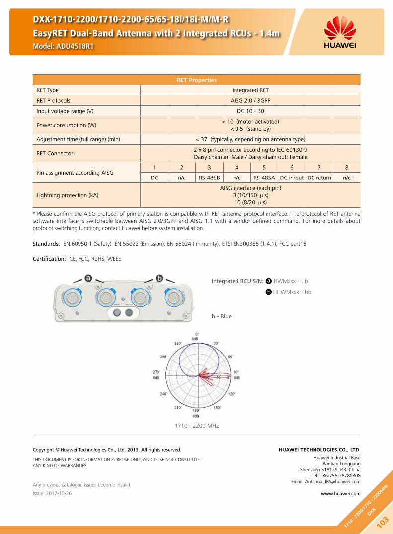
DXX-1710-2200/1710-2200-65/65-18i/18i-M/M-REasyRET Dual-Band Antenna with 2 Integrated RCUs - 1.4mModel: ADU4518R1
RET Properties
RET Type Integrated RET
RET Protocols AISG 2.0 / 3GPP
Input voltage range (V) DC 10 - 30
Power consumption (W) < 10 (motor activated)
< 0.5 (stand by)
Adjustment time (full range) (min) < 37 (typically, depending on antenna type)
RET Connector2 x 8 pin connector according to IEC 60130-9Daisy chain in: Male / Daisy chain out: Female
Pin assignment according AISG 1 2 3 4 5 6 7 8
DC n/c RS-485B n/c RS-485A DC in/out DC return n/c
Lightning protection (kA)AISG interface (each pin)
3 (10/350 μs)10 (8/20 μs)
Any previous catalogue issues become invalid.
Issue: 2012-10-26
HUAWEI TECHNOLOGIES CO., LTD.
Huawei Industrial BaseBantian Longgang
Shenzhen 518129, P.R. ChinaTel: +86-755-28780808
Email: [email protected]
www.huawei.com
Copyright © Huawei Technologies Co., Ltd. 2013. All rights reserved.
THIS DOCUMENT IS FOR INFORMATION PURPOSE ONLY, AND DOSE NOT CONSTITUTE ANY KIND OF WARRANTIES.
* Please confirm the AISG protocol of primary station is compatible with RET antenna protocol interface. The protocol of RET antenna software interface is switchable between AISG 2.0/3GPP and AISG 1.1 with a vendor defined command. For more details about protocol switching function, contact Huawei before system installation.
Standards: EN 60950-1 (Safety), EN 55022 (Emission), EN 55024 (Immunity), ETSI EN300386 (1.4.1), FCC part15
Integrated RCU S/N: HWMxxx…..b
HHWMxxx…bb
Certification: CE, FCC, RoHS, WEEE
1710 - 2200 MHz
a
b
b - Blue
103
1710
- 22
00/1
710 - 2
200M
Hz
DXX

DXX-1710-2200/1710-2200-65/65-19.5i/19.5i-M/M
Model: ADU451902
Electrical Properties
Frequency range (MHz)2 x (1710 - 2200)
1710 - 1880 1850 - 1990 1920 - 2170 2170 - 2200
Polarization +45° , -45°
Electrical downtilt (°) 0 - 6, continuously adjustable
Gain (dBi)0° 3° 6° 0° 3° 6° 0° 3° 6° 0° 3° 6°
18.5 18.7 18.6 18.9 19.1 18.8 19.1 19.4 18.9 19.1 19.3 18.8
Side lobe suppression for first side lobe above main beam (Typ.) (dB)
0° 3° 6° 0° 3° 6° 0° 3° 6° 0° 3° 6°
20 17 16 20 17 17 20 18 17 20 18 17
Horizontal 3dB beam width (°) 67 65 62 60
Vertical 3dB beam width (°) 5.0 4.7 4.5 4.1
VSWR < 1.5
Isolation between ports (dB) ≥ 30
Front to back ratio, copolar (dB) Typ. 28
Cross polar ratio (dB)0° Typ. 25
±60° Typ. 10
Max. power per input (W) 300 (at 50 ambient temperature)
Intermodulation IM3 (dBc) ≤ -153 (2 x 43 dBm carrier)
Impedance (Ω) 50
Grounding DC Ground
Mechanical Properties
Antenna dimensions (H x W x D) (mm) 1954 x 323 x 89
Antenna net weight (kg) 17.3
Bracket weight (kg) 4.6
Mechanical downtilt (°) 0 - 12
Mast diameter (mm) 50 - 115
Radome material Fiberglass
Radome colour Light grey
Operational temperature () -55 .. +65
Wind load (N)Frontal: 890 (at 150 km/h)Lateral: 170 (at 150 km/h)
Rear side: 1000 (at 150 km/h)
Max. operational wind speed (km/h) 150
Survival wind speed (km/h) 200
Connector 4 x 7/16 DIN Female
Connector position Bottom
104
1710 - 2200/1710 - 2200MHz
DXX

DXX-1710-2200/1710-2200-65/65-19.5i/19.5i-M/M
Model: ADU451902
1710 - 2200 MHz
Unit: mmL - Left Column R - Right Column
593643
31
HINT
Extraordinary operating conditions, such as heavy icing or storm wind, may result in the breakage of an antenna. These facts must be considered during the site planning process.
The installation team must be properly qualified and also be familiar with the relevant national safety regulations.
Any previous catalogue issues become invalid.
Issue: 2012-10-26
HUAWEI TECHNOLOGIES CO., LTD.
Huawei Industrial BaseBantian Longgang
Shenzhen 518129, P.R. ChinaTel: +86-755-28780808
Email: [email protected]
www.huawei.com
Copyright © Huawei Technologies Co., Ltd. 2013. All rights reserved.
THIS DOCUMENT IS FOR INFORMATION PURPOSE ONLY, AND DOSE NOT CONSTITUTE ANY KIND OF WARRANTIES.
1710 - 2200X
1710 - 2200X
+45° +45°
7/16 (F) 7/16 (F)7/16 (F) 7/16 (F)
-45° -45°
105
1710
- 22
00/1
710 - 2
200M
Hz
DXX

DXX-1710-2170/2490-2690-65/65-18i/18i-M/M-REasyRET Dual-Band Antenna with 2 Integrated RCUs - 1.4mModel: ADU4518R5
Preliminary Issue
Electrical Properties
Frequency range (MHz)1710 - 2170
2490 - 26901710 - 1880 1850 - 1990 1920 - 2170
Polarization +45° , -45°
Electrical downtilt (°) 0 - 12 , continuously adjustable
Gain (dBi)0° 6° 12° 0° 6° 12° 0° 6° 12° 0° 6° 12°
17.1 17.2 17.0 17.4 17.6 17.3 17.4 17.7 17.2 17.6 17.8 17.1
Side lobe suppression (Typ.) (dB)
-for first side lobe above main beam
-within 0° - 15° sector above horizon
0° 6° 12° 0° 6° 12° 0° 6° 12° 0° 6° 12°
18 17 16 18 17 16 18 17 16 17 17 16
16 16 15 16 16 15 16 16 15 15 16 15
Horizontal 3dB beam width (°) 66 64 61 60
Vertical 3dB beam width (°) 6.5 6.2 5.5 4.7
VSWR < 1.5
Isolation between ports (dB)Intra-system: ≥ 30Inter-system: ≥ 30
Front to back ratio, copolar (dB) Typ. 30
Cross polar ratio (dB)0° Typ. 20
±60° Typ. 10
Max. power per input (W) 250 (at 50 ambient temperature)
Intermodulation IM3 (dBc) ≤ -153 (2 x 43 dBm carrier)
Squint (°) Typ. 3.0
Tracking (dB) Avg. 2.0 (within 10dB HBW)
Impedance (Ω) 50
Grounding DC Ground
Mechanical Properties
Antenna dimensions (H x W x D) (mm) 1445 x 155 x 109
Antenna net weight (kg) 19.2
Bracket weight (kg) 2.6
Mechanical downtilt (°) 0 - 12
Mast diameter (mm) 50 - 115
Radome material Fiberglass
Radome colour Light grey
Operational temperature () -40 .. +65
Wind load (N)Frontal: 230 (at 150 km/h)Lateral: 215 (at 150 km/h)
Rear side: 395 (at 150 km/h)
Max. operational wind speed (km/h) 150
Survival wind speed (km/h) 200
Connector 4 x 7/16 DIN Female
Connector position Bottom
106
1710 - 2170/2490 - 2690MHz
DXX

DXX-1710-2170/2490-2690-65/65-18i/18i-M/M-REasyRET Dual-Band Antenna with 2 Integrated RCUs - 1.4mModel: ADU4518R5
Preliminary Issue
Any previous catalogue issues become invalid.
Issue: 2013-01-08
HUAWEI TECHNOLOGIES CO., LTD.
Huawei Industrial BaseBantian Longgang
Shenzhen 518129, P.R. ChinaTel: +86-755-28780808
Email: [email protected]
www.huawei.com
Copyright © Huawei Technologies Co., Ltd. 2013. All rights reserved.
THIS DOCUMENT IS FOR INFORMATION PURPOSE ONLY, AND DOSE NOT CONSTITUTE ANY KIND OF WARRANTIES.
RET Properties
RET Type Integrated RET
RET Protocols* AISG 2.0 / 3GPP
Input voltage range (V) DC 10 - 30
Power consumption (W) < 10 (motor activated)
< 0.5 (stand by)
Adjustment time (full range) (min) < 50 (typically, depending on antenna type)
RET Connector2 x 8 pin connector according to IEC 60130-9Daisy chain in: Male / Daisy chain out: Female
Pin assignment according AISG 1 2 3 4 5 6 7 8
DC n/c RS-485B n/c RS-485A DC in/out DC return n/c
Lightning protection (kA)AISG interface (each pin)
3 (10/350 μs)10 (8/20 μs)
HINT
Before the installation, check whether the antenna and base station support the same AISG protocol. If not, contact the technical support personnel of Huawei.
* Please confirm the AISG protocol of primary station is compatible with RET antenna protocol interface. The protocol of RET antenna software interface is switchable between AISG 2.0/3GPP and AISG 1.1 with a vendor defined command. For more details about protocol switching function, contact Huawei before system installation.
Standards: EN 60950-1 (Safety), EN 55022 (Emission), EN 55024 (Immunity), ETSI EN300386 (1.4.1), FCC part15
Certification: CE, FCC, RoHS, WEEE
107
1710
- 21
70/2
490 - 2
690M
Hz
DXX

DXX-1710-2690/1710-2690-65/65-16i/16i-M/M
Model: ADU451507
Mechanical Properties
Antenna dimensions (H x W x D) (mm) 790 x 299x 109
Antenna net weight (kg) 13
Bracket weight (kg) 4.6
Mechanical downtilt (°) 0 - 16
Mast diameter (mm) 50 - 115
Radome material Fiberglass
Radome colour Light grey
Operational temperature () -55 .. +65
Wind load (N)Frontal: 320 (at 150 km/h)Lateral: 60 (at 150 km/h)
Rear side: 365 (at 150 km/h)
Max. operational wind speed (km/h) 150
Survival wind speed (km/h) 200
Connector 4 x 7/16 DIN Female
Connector position Bottom
Any previous catalogue issues become invalid.
Issue: 2013-01-08
HUAWEI TECHNOLOGIES CO., LTD.
Huawei Industrial BaseBantian Longgang
Shenzhen 518129, P.R. ChinaTel: +86-755-28780808
Email: [email protected]
www.huawei.com
Copyright © Huawei Technologies Co., Ltd. 2013. All rights reserved.
THIS DOCUMENT IS FOR INFORMATION PURPOSE ONLY, AND DOSE NOT CONSTITUTE ANY KIND OF WARRANTIES.
Preliminary Issue
Electrical Properties
Frequency range (MHz)2 x (1710 - 2690)
1710 - 1990 1920 - 2200 2200 - 2490 2490 - 2690
Polarization +45° , -45°
Electrical downtilt (°) 0 - 14 , continuously adjustable
Gain (dBi)0° 7° 14° 0° 7° 14° 0° 7° 14° 0° 7° 14°
14.8 14.8 14.3 15.1 15.3 14.8 15.5 15.7 15.2 15.5 15.7 15.2
Side lobe suppression (Typ.) (dB)
-for first side lobe above main beam
-within 0° - 15° sector above horizon
0° 7° 14° 0° 7° 14° 0° 7° 14° 0° 7° 14°
17 16 15 17 16 15 17 16 15 17 16 15
16 15 15 16 15 15 16 15 15 16 15 15
Horizontal 3dB beam width (°) 67 65 63 60
Vertical 3dB beam width (°) 12 11 10 9
VSWR < 1.5
Isolation between ports (dB) ≥ 30
Front to back ratio, copolar (dB) Typ. 28
Cross polar ratio (dB)0° Typ. 20
±60° Typ. 10
Max. power per input (W) 250 (at 50 ambient temperature)
Intermodulation IM3 (dBc) ≤ -153 (2 x 43 dBm carrier)
Impedance (Ω) 50
Grounding DC Ground
108
1710 - 2690/1710 - 2690MHz
DXX
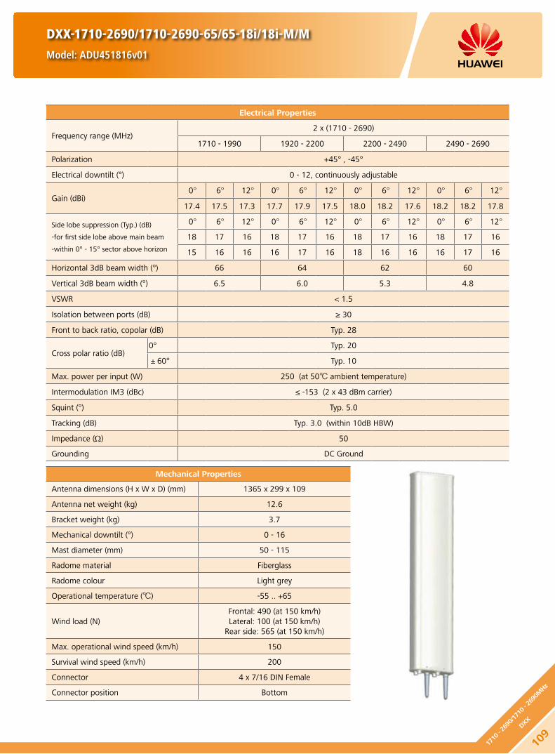
DXX-1710-2690/1710-2690-65/65-18i/18i-M/M
Model: ADU451816v01
Electrical Properties
Frequency range (MHz)2 x (1710 - 2690)
1710 - 1990 1920 - 2200 2200 - 2490 2490 - 2690
Polarization +45° , -45°
Electrical downtilt (°) 0 - 12, continuously adjustable
Gain (dBi)0° 6° 12° 0° 6° 12° 0° 6° 12° 0° 6° 12°
17.4 17.5 17.3 17.7 17.9 17.5 18.0 18.2 17.6 18.2 18.2 17.8
Side lobe suppression (Typ.) (dB)
-for first side lobe above main beam
-within 0° - 15° sector above horizon
0° 6° 12° 0° 6° 12° 0° 6° 12° 0° 6° 12°
18 17 16 18 17 16 18 17 16 18 17 16
15 16 16 16 17 16 18 16 16 16 17 16
Horizontal 3dB beam width (°) 66 64 62 60
Vertical 3dB beam width (°) 6.5 6.0 5.3 4.8
VSWR < 1.5
Isolation between ports (dB) ≥ 30
Front to back ratio, copolar (dB) Typ. 28
Cross polar ratio (dB)0° Typ. 20
±60° Typ. 10
Max. power per input (W) 250 (at 50 ambient temperature)
Intermodulation IM3 (dBc) ≤ -153 (2 x 43 dBm carrier)
Squint (°) Typ. 5.0
Tracking (dB) Typ. 3.0 (within 10dB HBW)
Impedance (Ω) 50
Grounding DC Ground
Mechanical Properties
Antenna dimensions (H x W x D) (mm) 1365 x 299 x 109
Antenna net weight (kg) 12.6
Bracket weight (kg) 3.7
Mechanical downtilt (°) 0 - 16
Mast diameter (mm) 50 - 115
Radome material Fiberglass
Radome colour Light grey
Operational temperature () -55 .. +65
Wind load (N)Frontal: 490 (at 150 km/h)Lateral: 100 (at 150 km/h)
Rear side: 565 (at 150 km/h)
Max. operational wind speed (km/h) 150
Survival wind speed (km/h) 200
Connector 4 x 7/16 DIN Female
Connector position Bottom
109
1710
- 26
90/1
710 - 2
690M
Hz
DXX

1710 - 2200 MHz 2200 - 2690 MHz
1710 - 2690X
1710 - 2690X
+45° +45°
7/16 (F) 7/16 (F)7/16 (F) 7/16 (F)
-45° -45°
DXX-1710-2690/1710-2690-65/65-18i/18i-M/M
Model: ADU451816v01
HINT
Extraordinary operating conditions, such as heavy icing or storm wind, may result in the breakage of an antenna. These facts must be considered during the site planning process.
The installation team must be properly qualified and also be familiar with the relevant national safety regulations.
Any previous catalogue issues become invalid.
Issue: 2013-01-08
HUAWEI TECHNOLOGIES CO., LTD.
Huawei Industrial BaseBantian Longgang
Shenzhen 518129, P.R. ChinaTel: +86-755-28780808
Email: [email protected]
www.huawei.com
Copyright © Huawei Technologies Co., Ltd. 2013. All rights reserved.
THIS DOCUMENT IS FOR INFORMATION PURPOSE ONLY, AND DOSE NOT CONSTITUTE ANY KIND OF WARRANTIES.
110
1710 - 2690/1710 - 2690MHz
DXX
Unit: mm
5855
5883

Electrical Properties
Frequency range (MHz)2 x (1710 - 2690)
1710 - 1990 1920 - 2200 2200 - 2490 2490 - 2690
Polarization +45° , -45°
Electrical downtilt (°) 0 - 12 , continuously adjustable
Gain (dBi)0° 6° 12° 0° 6° 12° 0° 6° 12° 0° 6° 12°
17.3 17.4 17.2 17.6 17.8 17.5 17.7 18.0 17.5 17.8 18.0 17.3
Side lobe suppression (Typ.) (dB)
-for first side lobe above main beam
-within 0° - 15° sector above horizon
0° 6° 12° 0° 6° 12° 0° 6° 12° 0° 6° 12°
18 17 16 18 17 16 18 17 16 17 17 16
16 16 15 16 16 15 16 16 15 15 16 15
Horizontal 3dB beam width (°) 66 63 60 60
Vertical 3dB beam width (°) 6.7 6.1 5.5 4.9
VSWR < 1.5
Isolation between ports (dB) ≥ 30
Front to back ratio, copolar (dB) Typ. 28
Cross polar ratio (dB)0° Typ. 20
±60° Typ. 10
Max. power per input (W) 250 (at 50 ambient temperature)
Intermodulation IM3 (dBc) ≤ -153 (2 x 43 dBm carrier)
Impedance (Ω) 50
Grounding DC Ground
Mechanical Properties
Antenna dimensions (H x W x D) (mm) 1365 x 299 x 109
Antenna net weight (kg) 15.6
Bracket weight (kg) 4.6
Mechanical downtilt (°) 0 - 16
Mast diameter (mm) 50 - 115
Radome material Fiberglass
Radome colour Light grey
Operational temperature () -40 .. +65
Wind load (N)Frontal: 490 (at 150 km/h)Lateral: 100 (at 150 km/h)
Rear side: 560 (at 150 km/h)
Max. operational wind speed (km/h) 150
Survival wind speed (km/h) 200
Connector 4 x 7/16 DIN Female
Connector position Bottom
Preliminary Issue
DXX-1710-2690/1710-2690-65/65-18i/18i-M/M-REasyRET Dual-Band Antenna with 2 Integrated RCUs - 1.4mModel: ADU4518R6
111
1710
- 26
90/1
710 - 2
690M
Hz
DXX

Any previous catalogue issues become invalid.
Issue: 2013-01-08
HUAWEI TECHNOLOGIES CO., LTD.
Huawei Industrial BaseBantian Longgang
Shenzhen 518129, P.R. ChinaTel: +86-755-28780808
Email: [email protected]
www.huawei.com
Copyright © Huawei Technologies Co., Ltd. 2013. All rights reserved.
THIS DOCUMENT IS FOR INFORMATION PURPOSE ONLY, AND DOSE NOT CONSTITUTE ANY KIND OF WARRANTIES.
Preliminary Issue
RET Properties
RET Type Integrated RET
RET Protocols* AISG 2.0 / 3GPP
Input voltage range (V) DC 10 - 30
Power consumption (W) < 10 (motor activated)
< 0.5 (stand by)
Adjustment time (full range) (min) < 50 (typically, depending on antenna type)
RET Connector2 x 8 pin connector according to IEC 60130-9Daisy chain in: Male / Daisy chain out: Female
Pin assignment according AISG 1 2 3 4 5 6 7 8
DC n/c RS-485B n/c RS-485A DC in/out DC return n/c
Lightning protection (kA)AISG interface (each pin)
3 (10/350 μs)10 (8/20 μs)
HINT
Before the installation, check whether the antenna and base station support the same AISG protocol. If not, contact the technical support personnel of Huawei.
* Please confirm the AISG protocol of primary station is compatible with RET antenna protocol interface. The protocol of RET antenna software interface is switchable between AISG 2.0/3GPP and AISG 1.1 with a vendor defined command. For more details about protocol switching function, contact Huawei before system installation.
Standards: EN 60950-1 (Safety), EN 55022 (Emission), EN 55024 (Immunity), ETSI EN300386 (1.4.1), FCC part15
Certification: CE, FCC, RoHS, WEEE
DXX-1710-2690/1710-2690-65/65-18i/18i-M/M-REasyRET Dual-Band Antenna with 2 Integrated RCUs - 1.4mModel: ADU4518R6
112
1710 - 2690/1710 - 2690MHz
DXX

Preliminary Issue
Electrical Properties
Frequency range (MHz)2 x (1710 - 2690)
1710 - 1990 1920 - 2200 2200 - 2490 2490 - 2690
Polarization +45° , -45°
Electrical downtilt (°) 0 - 8 , continuously adjustable
Gain (dBi)0° 4° 8° 0° 4° 8° 0° 4° 8° 0° 4° 8°
18.0 18.1 18.0 18.3 18.6 18.5 19.0 19.2 19.0 19.0 19.3 19.0
Side lobe suppression for first side lobe above main beam (Typ.) (dB)
0° 4° 8° 0° 4° 8° 0° 4° 8° 0° 4° 8°
18 17 16 18 17 16 18 17 16 17 17 16
Horizontal 3dB beam width (°) 66 63 60 60
Vertical 3dB beam width (°) 5.2 4.8 4.4 3.9
VSWR < 1.5
Isolation between ports (dB) ≥ 30
Front to back ratio, copolar (dB) Typ. 28
Cross polar ratio (dB)0° Typ. 20
±60° Typ. 10
Max. power per input (W) 250 (at 50 ambient temperature)
Intermodulation IM3 (dBc) ≤ -153 (2 x 43 dBm carrier)
Impedance (Ω) 50
Grounding DC Ground
Mechanical Properties
Antenna dimensions (H x W x D) (mm) 1690 x 299 x 109
Antenna net weight (kg) 18
Bracket weight (kg) 4.6
Mechanical downtilt (°) 0 - 12
Mast diameter (mm) 50 - 115
Radome material Fiberglass
Radome colour Light grey
Operational temperature () -55 .. +65
Wind load (N)Frontal: 620 (at 150 km/h)Lateral: 130 (at 150 km/h)
Rear side: 715 (at 150 km/h)
Max. operational wind speed (km/h) 150
Survival wind speed (km/h) 200
Connector 4 x 7/16 DIN Female
Connector position Bottom
Any previous catalogue issues become invalid.
Issue: 2013-01-08
HUAWEI TECHNOLOGIES CO., LTD.
Huawei Industrial BaseBantian Longgang
Shenzhen 518129, P.R. ChinaTel: +86-755-28780808
Email: [email protected]
www.huawei.com
Copyright © Huawei Technologies Co., Ltd. 2013. All rights reserved.
THIS DOCUMENT IS FOR INFORMATION PURPOSE ONLY, AND DOSE NOT CONSTITUTE ANY KIND OF WARRANTIES.
DXX-1710-2690/1710-2690-65/65-19.5i/19.5i-M/M
Model: ADU451901v01
113
1710
- 26
90/1
710 - 2
690M
Hz
DXX

Electrical Properties
Frequency range (MHz)2 x (2300 - 2690)
2300 - 2490 2490 - 2690
Polarization +45° , -45°
Electrical downtilt (°) 0 - 10 , continuously adjustable
Gain (dBi)0° 5° 10° 0° 5° 10°
17.0 17.4 17.3 17.4 17.8 17.0
Side lobe suppression for first side lobe above main beam (Typ.) (dB)
0° 5° 10° 0° 5° 10°
20 20 19 20 18 20
Horizontal 3dB beam width (°) 64 61
Vertical 3dB beam width (°) 7.0 6.4
VSWR < 1.5
Isolation between ports (dB) ≥ 30
Front to back ratio, copolar (dB) Typ. 26
Cross polar ratio (dB) 0° Typ. 20
Max. power per input (W) 250 (at 50 ambient temperature)
Intermodulation IM3 (dBc) ≤ -150 (2 x 43 dBm carrier)
Impedance (Ω) 50
Grounding DC Ground
Mechanical Properties
Antenna dimensions (H x W x D) (mm) 1060 x 289 x 85
Antenna net weight (kg) 10.2
Bracket weight (kg) 4.6
Mechanical downtilt (°) 0 - 16
Mast diameter (mm) 50 - 115
Radome material Fiberglass
Radome colour Light grey
Operational temperature () -55 .. +65
Wind load (N)Frontal: 230 (at 150 km/h)Lateral: 100 (at 150 km/h)
Rear side: 340 (at 150 km/h)
Max. operational wind speed (km/h) 150
Survival wind speed (km/h) 200
Connector 4 x 7/16 DIN Female
Connector position Bottom
DXX-2300-2690/2300-2690-65/65-18i/18i-M
Model: A25451805
114
2300 - 2690/2300 - 2690MHz
DXX

1710 - 2200 MHz 2200 - 2690 MHz
DXX-2300-2690/2300-2690-65/65-18i/18i-M
Model: A25451805
HINT
Extraordinary operating conditions, such as heavy icing or storm wind, may result in the breakage of an antenna. These facts must be considered during the site planning process.
The installation team must be properly qualified and also be familiar with the relevant national safety regulations.
Any previous catalogue issues become invalid.
Issue: 2012-10-26
HUAWEI TECHNOLOGIES CO., LTD.
Huawei Industrial BaseBantian Longgang
Shenzhen 518129, P.R. ChinaTel: +86-755-28780808
Email: [email protected]
www.huawei.com
Copyright © Huawei Technologies Co., Ltd. 2013. All rights reserved.
THIS DOCUMENT IS FOR INFORMATION PURPOSE ONLY, AND DOSE NOT CONSTITUTE ANY KIND OF WARRANTIES.
2300 - 2690X
2300 - 2690X
+45°+45°
7/16 (F) 7/16 (F)7/16 (F) 7/16 (F)
-45°-45°
52 48
Unit: mmL - Left Column R - Right Column
115
2300
- 26
90/2
300 - 2
690M
Hz
DXX

DXXX-790-960/1710-2180/1710-2180-65/65/65-14i/14i/14i-M/M/M
Model: ATR451500
Electrical Properties
Frequency range (MHz)790 - 960 2 x (1710 - 2180)
790 - 862 824 - 894 880 - 960 1710 - 1880 1850 - 1990 1920 - 2180
Polarization +45° , -45°
Electrical downtilt (°) 0 - 14, continuously adjustable 0 - 14, continuously adjustable
Gain (dBi)
0° 7° 14° 0° 7° 14° 0° 7° 14° 0° 7° 14° 0° 7° 14° 0° 7° 14°
14.7 14.8 14.5 15.0 14.8 14.7 15.0 14.8 14.6
Bottom 14.6 14.5 14.3 15.0 14.9 14.5 15.3 15.2 14.7
Top 14.5 14.5 14.0 14.9 14.7 14.1 15.1 15.0 14.3
Side lobe suppression for first side lobe above main beam (Typ.) (dB)
0° 7° 14° 0° 7° 14° 0° 7° 14° 0° 7° 14° 0° 7° 14° 0° 7° 14°
18 17 15 19 18 16 19 18 15 17 17 15 18 18 15 17 17 15
Horizontal 3dB beam width (°) 69 68 67 63 61 60
Vertical 3dB beam width (°) 15.5 14.8 13.8 13.6 12.8 12.1
VSWR < 1.5
Isolation between ports (dB)Intra-system: ≥ 30
Inter-system (790 - 960 / 1710 - 2180 MHz): ≥ 40Inter-system (1710 - 2180 / 1710 - 2180 MHz): ≥ 30
Front to back ratio, copolar (dB) Typ. 28 Typ. 28
Cross polar ratio (dB)0° Typ. 26 Typ. 20
±60° Typ. 10 Typ. 10
Max. power per input (W) 500 (at 50 ambient temperature) 300 (at 50 ambient temperature)
Intermodulation IM3 (dBc) ≤ -153 (2 x 43 dBm carrier)
Squint (°) Avg. 2.5
Tracking (dB) Avg. 2.5 (within 10dB HBW)
Impedance (Ω) 50
Grounding DC Ground
Mechanical Properties
Antenna dimensions (H x W x D) (mm) 1454 x 259 x 135
Antenna net weight (kg) 15.1
Bracket weight (kg) 4.6
Mechanical downtilt (°) 0 - 16
Mast diameter (mm) 50 - 115
Radome material Fiberglass
Radome colour Light grey
Operational temperature () -55 .. +65
Wind load (N)Frontal: 480 (at 150 km/h)Lateral: 250 (at 150 km/h)
Rear side: 635 (at 150 km/h)
Max. operational wind speed (km/h) 150
Survival wind speed (km/h) 200
Connector 6 x 7/16 DIN Female
Connector position Bottom
116
790 - 960/1710 - 2180/
1710 - 2180MHz
DXXX

DXXX-790-960/1710-2180/1710-2180-65/65/65-14i/14i/14i-M/M/M
Model: ATR451500
790 - 960 MHz 1710 - 2180 MHz(Bottom)
1710 - 2180 MHz(Top)
790 - 960X
+45°
7/16 (F) 7/16 (F) 7/16 (F)7/16 (F) 7/16 (F) 7/16 (F)
-45°
1710 - 2180TopX
+45° -45°
1710 - 2180Bottom
X
+45° -45°
55
17
56
70
61 44
Unit: mmT - Top Column B - Bottom Column
HINT
Extraordinary operating conditions, such as heavy icing or storm wind, may result in the breakage of an antenna. These facts must be considered during the site planning process.
The installation team must be properly qualified and also be familiar with the relevant national safety regulations.
Any previous catalogue issues become invalid.
Issue: 2012-10-26
HUAWEI TECHNOLOGIES CO., LTD.
Huawei Industrial BaseBantian Longgang
Shenzhen 518129, P.R. ChinaTel: +86-755-28780808
Email: [email protected]
www.huawei.com
Copyright © Huawei Technologies Co., Ltd. 2013. All rights reserved.
THIS DOCUMENT IS FOR INFORMATION PURPOSE ONLY, AND DOSE NOT CONSTITUTE ANY KIND OF WARRANTIES.
11779
0 - 9
60/1
710 - 2
180/
1710
- 21
80M
Hz
DXXX

DXXX-790-960/1710-2180/1710-2180-65/65/65-16i/16i/16i-M/M/M
Model: ATR451602v01
Electrical Properties
Frequency range (MHz)790 - 960 2 x (1710 - 2180)
790 - 862 824 - 894 880 - 960 1710 - 1880 1850 - 1990 1920 - 2180
Polarization +45° , -45°
Electrical downtilt (°) 0 - 12, continuously adjustable 0 - 12, continuously adjustable
Gain (dBi)
0° 6° 12° 0° 6° 12° 0° 6° 12° 0° 6° 12° 0° 6° 12° 0° 6° 12°
16.2 16.0 15.5 16.3 16.3 15.6 16.5 16.2 15.6
Bottom 15.9 16.0 15.6 16.2 16.4 15.8 16.3 16.5 16.0
Top 16.0 16.2 15.6 16.3 16.4 15.7 16.3 16.5 15.7
Side lobe suppression for first side lobe above main beam (Typ.) (dB)
0° 6° 12° 0° 6° 12° 0° 6° 12° 0° 6° 12° 0° 6° 12° 0° 6° 12°
18 17 15 19 18 16 19 18 15 17 17 15 18 18 15 17 17 15
Horizontal 3dB beam width (°) 69 66 65 64 62 60
Vertical 3dB beam width (°) 10.7 10.1 9.4Bottom: 9.6
Top: 8.5Bottom: 8.9
Top: 8.0Bottom: 8.3
Top: 7.5
VSWR < 1.5
Isolation between ports (dB)Intra-system: ≥ 30
Inter-system (790 - 960 // 1710 - 2180 MHz): ≥ 40Inter-system (1710 - 2180 // 1710 - 2180 MHz): ≥ 35
Front to back ratio, copolar (dB) Typ. 28 Typ. 29
Cross polar ratio (dB)0° Typ. 26 Typ. 20
±60° Typ. 10 Typ. 10
Max. power per input (W) 500 (at 50 ambient temperature) 300 (at 50 ambient temperature)
Intermodulation IM3 (dBc) ≤ -153 (2 x 43 dBm carrier)
Squint (°) Avg. 2.5
Tracking (dB) Avg. 2.5 (within 10dB HBW)
Impedance (Ω) 50
Grounding DC Ground
Mechanical Properties
Antenna dimensions (H x W x D) (mm) 2098 x 259 x 135
Antenna net weight (kg) 19.4
Bracket weight (kg) 4.6
Mechanical downtilt (°) 0 - 12
Mast diameter (mm) 50 - 115
Radome material Fiberglass
Radome colour Light grey
Operational temperature () -55 .. +65
Wind load (N) Frontal: 730 (at 150 km/h) Lateral: 380 (at 150 km/h)
Rear side: 965 (at 150 km/h)
Max. operational wind speed (km/h) 150
Survival wind speed (km/h) 200
Connector 6 x 7/16 DIN Female
Connector position Bottom
118
790 - 960/1710 - 2180/
1710 - 2180MHz
DXXX

DXXX-790-960/1710-2180/1710-2180-65/65/65-16i/16i/16i-M/M/M
Model: ATR451602v01
790 - 960 MHz 1710 - 2180 MHz(Bottom)
1710 - 2180 MHz(Top)
55
17
56
70
61 44
Unit: mmT - Top Column B - Bottom Column
HINT
Extraordinary operating conditions, such as heavy icing or storm wind, may result in the breakage of an antenna. These facts must be considered during the site planning process.
The installation team must be properly qualified and also be familiar with the relevant national safety regulations.
Any previous catalogue issues become invalid.
Issue: 2012-10-26
HUAWEI TECHNOLOGIES CO., LTD.
Huawei Industrial BaseBantian Longgang
Shenzhen 518129, P.R. ChinaTel: +86-755-28780808
Email: [email protected]
www.huawei.com
Copyright © Huawei Technologies Co., Ltd. 2013. All rights reserved.
THIS DOCUMENT IS FOR INFORMATION PURPOSE ONLY, AND DOSE NOT CONSTITUTE ANY KIND OF WARRANTIES.
790 - 960X
+45°
7/16 (F) 7/16 (F) 7/16 (F)7/16 (F) 7/16 (F) 7/16 (F)
-45°
1710 - 2180TopX
+45° -45°
1710 - 2180Bottom
X
+45° -45°
11979
0 - 9
60/1
710 - 2
180/
1710
- 21
80M
Hz
DXXX

Electrical Properties
Frequency range (MHz)790 - 960 2 x (1710 - 2180)
790 - 862 824 - 894 880 - 960 1710 - 1880 1850 - 1990 1920 - 2180
Polarization +45° , -45°
Electrical downtilt (°) 0 - 12 , continuously adjustable 0 - 12 , continuously adjustable
Gain (dBi)
0° 6° 12° 0° 6° 12° 0° 6° 12° 0° 6° 12° 0° 6° 12° 0° 6° 12°
16.2 16.0 15.5 16.3 16.3 15.6 16.5 16.2 15.6
Bottom 15.9 16.0 15.6 16.2 16.4 15.8 16.3 16.5 16.0
Top 16.0 16.2 15.6 16.3 16.4 15.7 16.3 16.5 15.7
Side lobe suppression for first side lobe above main beam (Typ.) (dB)
0° 6° 12° 0° 6° 12° 0° 6° 12° 0° 6° 12° 0° 6° 12° 0° 6° 12°
18 17 15 19 18 16 19 18 15 17 17 15 18 18 15 17 17 15
Horizontal 3dB beam width (°) 69 66 65 64 62 60
Vertical 3dB beam width (°) 10.7 10.1 9.4Bottom: 9.6
Top: 8.5Bottom: 8.9
Top: 8.0Bottom: 8.3
Top: 7.5
VSWR < 1.5
Isolation between ports (dB)Intra-system: ≥ 30
Inter-system (790 - 960 // 1710 - 2180 MHz): ≥ 40Inter-system (1710 - 2180 // 1710 - 2180 MHz): ≥ 35
Front to back ratio, copolar (dB) Typ. 28 Typ. 29
Cross polar ratio (dB)0° Typ. 26 Typ. 20
±60° Typ. 10 Typ. 10
Max. power per input (W) 500 (at 50 ambient temperature) 300 (at 50 ambient temperature)
Intermodulation IM3 (dBc) ≤ -153 (2 x 43 dBm carrier)
Squint (°) Avg. 2.5
Tracking (dB) Avg. 2.5 (within 10dB HBW)
Impedance (Ω) 50
Grounding DC Ground
Mechanical Properties
Antenna dimensions (H x W x D) (mm) 2098 x 259 x 135
Antenna net weight (kg) 20.7
Bracket weight (kg) 5.6
Mechanical downtilt (°) 0 - 12
Mast diameter (mm) 50 - 115
Radome material Fiberglass
Radome colour Light grey
Operational temperature () -40 .. +65
Wind load (N) Frontal: 730 (at 150 km/h) Lateral: 380 (at 150 km/h)
Rear side: 965 (at 150 km/h)
Max. operational wind speed (km/h) 150
Survival wind speed (km/h) 200
Connector 6 x 7/16 DIN Female
Connector position Bottom
DXXX-790-960/1710-2180/1710-2180-65/65/65-16.5i/16.5i/16.5i-M/M/M-REasyRET Tri-Band Antenna with 3 Integrated RCUs - 2.0mModel: ATR4516R0
120
790 - 960/1710 - 2180/
1710 - 2180MHz
DXXX

DXXX-790-960/1710-2180/1710-2180-65/65/65-16.5i/16.5i/16.5i-M/M/M-REasyRET Tri-Band Antenna with 3 Integrated RCUs - 2.0mModel: ATR4516R0
RET Properties
RET Type Integrated RET
RET Protocols AISG 2.0 / 3GPP
Input voltage range (V) DC 10 - 30
Power consumption (W) < 10 (motor activated)
< 0.5 (stand by)
Adjustment time (full range) (min) < 37 (typically, depending on antenna type)
RET Connector2 x 8 pin connector according to IEC 60130-9Daisy chain in: Male / Daisy chain out: Female
Pin assignment according AISG 1 2 3 4 5 6 7 8
DC n/c RS-485B n/c RS-485A DC in/out DC return n/c
Lightning protection (kA)AISG interface (each pin)
3 (10/350 μs)10 (8/20 μs)
Any previous catalogue issues become invalid.
Issue: 2012-10-26
HUAWEI TECHNOLOGIES CO., LTD.
Huawei Industrial BaseBantian Longgang
Shenzhen 518129, P.R. ChinaTel: +86-755-28780808
Email: [email protected]
www.huawei.com
Copyright © Huawei Technologies Co., Ltd. 2013. All rights reserved.
THIS DOCUMENT IS FOR INFORMATION PURPOSE ONLY, AND DOSE NOT CONSTITUTE ANY KIND OF WARRANTIES.
* Please confirm the AISG protocol of primary station is compatible with RET antenna protocol interface. The protocol of RET antenna software interface is switchable between AISG 2.0/3GPP and AISG 1.1 with a vendor defined command. For more details about protocol switching function, contact Huawei before system installation.
Standards: EN 60950-1 (Safety), EN 55022 (Emission), EN 55024 (Immunity), ETSI EN300386 (1.4.1), FCC part15
Integrated RCU S/N: HWMxxx……r
HWMxxx……bT
HWMxxx…bbB
Certification: CE, FCC, RoHS, WEEE
790 - 960 MHz 1710 - 2180 MHz (Bottom) 1710 - 2180 MHz (Top)
a
b
c
r - Red b - Blue
T - Top Column B - Bottom Column
12179
0 - 9
60/1
710 - 2
180/
1710
- 21
80M
Hz
DXXX

Electrical Properties
Frequency range (MHz)790 - 960 2 x (1710 - 2180)
790 - 862 824 - 894 880 - 960 1710 - 1880 1850 - 1990 1920 - 2180
Polarization +45° , -45°
Electrical downtilt (°) 0 - 10, continuously adjustable 0 - 10, continuously adjustable
Gain (dBi)
0° 5° 10° 0° 5° 10° 0° 5° 10° 0° 5° 10° 0° 5° 10° 0° 5° 10°
16.7 16.8 16.6 16.9 17.1 16.7 17.1 17.3 17.0
Bottom 17.0 17.1 16.6 17.6 17.6 16.8 17.4 17.6 17.0
Top 16.8 17.1 16.7 17.1 17.3 16.8 16.9 17.3 16.9
Side lobe suppression for first side lobe above main beam (Typ.) (dB)
0° 5° 10° 0° 5° 10° 0° 5° 10° 0° 5° 10° 0° 5° 10° 0° 5° 10°
19 16 19 19 17 19 19 17 18 15 20 20 15 15 16 18 17 15
Horizontal 3dB beam width (°) 69 66 65 63 62 60
Vertical 3dB beam width (°) 8.4 8.0 7.5Bottom: 7.5
Top: 7.0Bottom: 7.0
Top: 6.5Bottom: 6.6
Top: 6.1
VSWR < 1.5
Isolation between ports (dB)Intra-system: ≥ 30
Inter-system (790 - 960 // 1710 - 2180 MHz): ≥ 40Inter-system (1710 - 2180 // 1710 - 2180 MHz): ≥ 40
Front to back ratio, copolar (dB) Typ. 28 Typ. 29
Cross polar ratio (dB)0° Typ. 28 Typ. 20
±60° Typ. 10 Typ. 10
Max. power per input (W) 500 (at 50 ambient temperature) 300 (at 50 ambient temperature)
Intermodulation IM3 (dBc) ≤ -153 (2 x 43 dBm carrier)
Squint (°) Avg. 2.5
Tracking (dB) Avg. 1.0 (within 10dB HBW)
Impedance (Ω) 50
Grounding DC Ground
Mechanical Properties
Antenna dimensions (H x W x D) (mm) 2680 x 259 x 135
Antenna net weight (kg) 23
Bracket weight (kg) 5.6
Mechanical downtilt (°) 0 - 8
Mast diameter (mm) 50 - 115
Radome material Fiberglass
Radome colour Light grey
Operational temperature () -55 .. +65
Wind load (N) Frontal: 970 (at 150 km/h) Lateral: 500 (at 150 km/h)
Rear side: 1285 (at 150 km/h)
Max. operational wind speed (km/h) 150
Survival wind speed (km/h) 200
Connector 6 x 7/16 DIN Female
Connector position Bottom
DXXX-790-960/1710-2180/1710-2180-65/65/65-17.5i/17.5i/17.5i-M/M/M
Model: ATR451704v01
122
790 - 960/1710 - 2180/
1710 - 2180MHz
DXXX

DXXX-790-960/1710-2180/1710-2180-65/65/65-17.5i/17.5i/17.5i-M/M/M
Model: ATR451704v01
790 - 960 MHz 1710 - 2180 MHz(Bottom)
1710 - 2180 MHz(Top)
55
17
56
70
61 44
Unit: mm
T - Top Column B - Bottom Column
HINT
Extraordinary operating conditions, such as heavy icing or storm wind, may result in the breakage of an antenna. These facts must be considered during the site planning process.
The installation team must be properly qualified and also be familiar with the relevant national safety regulations.
Any previous catalogue issues become invalid.
Issue: 2012-10-26
HUAWEI TECHNOLOGIES CO., LTD.
Huawei Industrial BaseBantian Longgang
Shenzhen 518129, P.R. ChinaTel: +86-755-28780808
Email: [email protected]
www.huawei.com
Copyright © Huawei Technologies Co., Ltd. 2013. All rights reserved.
THIS DOCUMENT IS FOR INFORMATION PURPOSE ONLY, AND DOSE NOT CONSTITUTE ANY KIND OF WARRANTIES.
790 - 960X
+45°
7/16 (F) 7/16 (F) 7/16 (F)7/16 (F) 7/16 (F) 7/16 (F)
-45°
1710 - 2180TopX
+45° -45°
1710 - 2180Bottom
X
+45° -45°
12379
0 - 9
60/1
710 - 2
180/
1710
- 21
80M
Hz
DXXX

Electrical Properties
Frequency range (MHz)790 - 960 2 x (1710 - 2180)
790 - 862 824 - 894 880 - 960 1710 - 1880 1850 - 1990 1920 - 2180
Polarization +45° , -45°
Electrical downtilt (°) 0 - 12, continuously adjustable 0 - 12, continuously adjustable
Gain (dBi)
0° 6° 12° 0° 6° 12° 0° 6° 12° 0° 6° 12° 0° 6° 12° 0° 6° 12°
16.0 16.0 15.3 16.1 16.1 15.5 16.3 16.2 15.6
Bottom 15.7 15.8 15.4 16.0 16.2 15.6 16.1 16.3 15.8
Top 15.9 16.1 15.5 16.2 16.3 15.6 16.2 16.4 15.6
Side lobe suppression (Typ.) (dB)
-for first side lobe above main beam
-within 0° - 15° sector above horizon
0° 6° 12° 0° 6° 12° 0° 6° 12° 0° 6° 12° 0° 6° 12° 0° 6° 12°
18 17 15 19 18 16 19 18 15 17 17 15 18 18 15 17 17 15
15 16 15 15 16 15 15 16 15 16 16 15 16 16 15 16 16 15
Horizontal 3dB beam width (°) 69 66 65 64 62 60
Vertical 3dB beam width (°) 10.7 10.1 9.4Bottom: 9.6
Top: 8.5Bottom: 8.9
Top: 8.0Bottom: 8.3
Top: 7.5
VSWR < 1.5
Isolation between ports (dB)Intra-system: ≥ 30
Inter-system (790 - 960 // 1710 - 2180 MHz): ≥ 40Inter-system (1710 - 2180 // 1710 - 2180 MHz): ≥ 35
Front to back ratio, copolar (dB) Typ. 28 Typ. 29
Cross polar ratio (dB)0° Typ. 26 Typ. 20
±60° Typ. 10 Typ. 10
Max. power per input (W) 500 (at 50 ambient temperature) 300 (at 50 ambient temperature)
Intermodulation IM3 (dBc) ≤ -153 (2 x 43 dBm carrier)
Squint (°) Avg. 2.5
Tracking (dB) Avg. 2.5 (within 10dB HBW)
Impedance (Ω) 50
Grounding DC Ground
Mechanical Properties
Antenna dimensions (H x W x D) (mm) 2098 x 259 x 135
Antenna net weight (kg) 20.4
Bracket weight (kg) 4.6
Mechanical downtilt (°) 0 - 12
Mast diameter (mm) 50 - 115
Radome material Fiberglass
Radome colour Light grey
Operational temperature () -55 .. +65
Wind load (N) Frontal: 730 (at 150 km/h) Lateral: 380 (at 150 km/h)
Rear side: 965 (at 150 km/h)
Max. operational wind speed (km/h) 150
Survival wind speed (km/h) 200
Connector 6 x 7/16 DIN Female
Connector position Bottom
DXXX-790-960/1710-2180/1710-2180-65/65/65-16.5i/16.5i/16.5i-M/M/M-ESLS Model: ATR451612
124
790 - 960/1710 - 2180/
1710 - 2180MHz
DXXX

790 - 960 MHz 1710 - 2180 MHz(Bottom)
1710 - 2180 MHz(Top)
55
17
56
70
61 44
Unit: mm
T - Top Column B - Bottom Column
HINT
Extraordinary operating conditions, such as heavy icing or storm wind, may result in the breakage of an antenna. These facts must be considered during the site planning process.
The installation team must be properly qualified and also be familiar with the relevant national safety regulations.
Any previous catalogue issues become invalid.
Issue: 2012-10-26
HUAWEI TECHNOLOGIES CO., LTD.
Huawei Industrial BaseBantian Longgang
Shenzhen 518129, P.R. ChinaTel: +86-755-28780808
Email: [email protected]
www.huawei.com
Copyright © Huawei Technologies Co., Ltd. 2013. All rights reserved.
THIS DOCUMENT IS FOR INFORMATION PURPOSE ONLY, AND DOSE NOT CONSTITUTE ANY KIND OF WARRANTIES.
DXXX-790-960/1710-2180/1710-2180-65/65/65-16.5i/16.5i/16.5i-M/M/M-ESLS Model: ATR451612
790 - 960X
+45°
7/16 (F) 7/16 (F) 7/16 (F)7/16 (F) 7/16 (F) 7/16 (F)
-45°
1710 - 2180TopX
+45° -45°
1710 - 2180Bottom
X
+45° -45°
12579
0 - 9
60/1
710 - 2
180/
1710
- 21
80M
Hz
DXXX

Electrical Properties
Frequency range (MHz)790 - 960 2 x (1710 - 2180)
790 - 862 824 - 894 880 - 960 1710 - 1880 1850 - 1990 1920 - 2180
Polarization +45° , -45°
Electrical downtilt (°) 0 - 10, continuously adjustable 0 - 10, continuously adjustable
Gain (dBi)
0° 5° 10° 0° 5° 10° 0° 5° 10° 0° 5° 10° 0° 5° 10° 0° 5° 10°
16.7 16.8 16.6 16.9 17.1 16.7 17.1 17.3 17.0
Bottom 17.0 17.0 16.6 17.6 17.4 16.8 17.4 17.4 17.0
Top 16.8 17.1 16.7 17.1 17.3 16.8 16.9 17.3 16.9
Side lobe suppression (Typ.) (dB)
-for first side lobe above main beam
-within 0° - 15° sector above horizon
0° 5° 10° 0° 5° 10° 0° 5° 10° 0° 5° 10° 0° 5° 10° 0° 5° 10°
19 16 19 19 17 19 19 17 18 15 20 20 15 15 16 18 17 15
15 16 15 15 16 15 15 16 15 16 16 15 16 16 15 16 16 15
Horizontal 3dB beam width (°) 69 66 65 63 62 60
Vertical 3dB beam width (°) 8.4 8 7.5Bottom: 7.5
Top: 7.0Bottom: 7.0
Top: 6.5Bottom: 6.6
Top: 6.1
VSWR < 1.5
Isolation between ports (dB)Intra-system: ≥ 30
Inter-system (790 - 960 // 1710 - 2180 MHz): ≥ 40Inter-system (1710 - 2180 // 1710 - 2180 MHz): ≥ 40
Front to back ratio, copolar (dB) Typ. 28 Typ. 29
Cross polar ratio (dB)0° Typ. 28 Typ. 20
±60° Typ. 10 Typ. 10
Max. power per input (W) 500 (at 50 ambient temperature) 300 (at 50 ambient temperature)
Intermodulation IM3 (dBc) ≤ -153 (2 x 43 dBm carrier)
Squint (°) Avg. 2.5
Tracking (dB) Avg. 1.0 (within 10dB HBW)
Impedance (Ω) 50
Grounding DC Ground
Mechanical Properties
Antenna dimensions (H x W x D) (mm) 2680 x 259 x 135
Antenna net weight (kg) 24.7
Bracket weight (kg) 5.6
Mechanical downtilt (°) 0 - 8
Mast diameter (mm) 50 - 115
Radome material Fiberglass
Radome colour Light grey
Operational temperature () -55 .. +65
Wind load (N) Frontal: 970 (at 150 km/h) Lateral: 500 (at 150 km/h)
Rear side: 1285 (at 150 km/h)
Max. operational wind speed (km/h) 150
Survival wind speed (km/h) 200
Connector 6 x 7/16 DIN Female
Connector position Bottom
DXXX-790-960/1710-2180/1710-2180-65/65/65-17.5i/17.5i/17.5i-M/M/M-ESLS Model: ATR451713
126
790 - 960/1710 - 2180/
1710 - 2180MHz
DXXX

790 - 960 MHz 1710 - 2180 MHz(Bottom)
1710 - 2180 MHz(Top)
55
17
56
70
61 44
Unit: mm
T - Top Column B - Bottom Column
HINT
Extraordinary operating conditions, such as heavy icing or storm wind, may result in the breakage of an antenna. These facts must be considered during the site planning process.
The installation team must be properly qualified and also be familiar with the relevant national safety regulations.
Any previous catalogue issues become invalid.
Issue: 2012-10-26
HUAWEI TECHNOLOGIES CO., LTD.
Huawei Industrial BaseBantian Longgang
Shenzhen 518129, P.R. ChinaTel: +86-755-28780808
Email: [email protected]
www.huawei.com
Copyright © Huawei Technologies Co., Ltd. 2013. All rights reserved.
THIS DOCUMENT IS FOR INFORMATION PURPOSE ONLY, AND DOSE NOT CONSTITUTE ANY KIND OF WARRANTIES.
DXXX-790-960/1710-2180/1710-2180-65/65/65-17.5i/17.5i/17.5i-M/M/M-ESLS Model: ATR451713
790 - 960X
+45°
7/16 (F) 7/16 (F) 7/16 (F)7/16 (F) 7/16 (F) 7/16 (F)
-45°
1710 - 2180TopX
+45° -45°
1710 - 2180Bottom
X
+45° -45°
12779
0 - 9
60/1
710 - 2
180/
1710
- 21
80M
Hz
DXXX

DXXX-790-960/1710-2180/1710-2180-65/65/65-17.5i/17.5i/17.5i-M/M/M-REasyRET Tri-Band Antenna with 3 Integrated RCUs - 2.6mModel: ATR4517R0
Electrical Properties
Frequency range (MHz)790 - 960 2 x (1710 - 2180)
790 - 862 824 - 894 880 - 960 1710 - 1880 1850 - 1990 1920 - 2180
Polarization +45° , -45°
Electrical downtilt (°) 0 - 10 , continuously adjustable 0 - 10 , continuously adjustable
Gain (dBi)
0° 5° 10° 0° 5° 10° 0° 5° 10° 0° 5° 10° 0° 5° 10° 0° 5° 10°
16.7 16.8 16.6 16.9 17.1 16.7 17.1 17.3 17.0
Bottom 17.0 17.1 16.6 17.6 17.6 16.8 17.4 17.6 17.0
Top 16.8 17.1 16.7 17.1 17.3 16.8 16.9 17.3 16.9
Side lobe suppression for first side lobe above main beam (Typ.) (dB)
0° 5° 10° 0° 5° 10° 0° 5° 10° 0° 5° 10° 0° 5° 10° 0° 5° 10°
19 16 19 19 17 19 19 17 18 15 20 20 15 15 16 18 17 15
Horizontal 3dB beam width (°) 69 66 65 63 62 60
Vertical 3dB beam width (°) 8.4 8.0 7.5Bottom: 7.5
Top: 7.0Bottom: 7.0
Top: 6.5Bottom: 6.6
Top: 6.1
VSWR < 1.5
Isolation between ports (dB)Intra-system: ≥ 30
Inter-system (790 - 960 // 1710 - 2180 MHz): ≥ 40Inter-system (1710 - 2180 // 1710 - 2180 MHz): ≥ 40
Front to back ratio, copolar (dB) Typ. 28 Typ. 29
Cross polar ratio (dB)0° Typ. 28 Typ. 20
±60° Typ. 10 Typ. 10
Max. power per input (W) 500 (at 50 ambient temperature) 300 (at 50 ambient temperature)
Intermodulation IM3 (dBc) ≤ -153 (2 x 43 dBm carrier)
Squint (°) Avg. 2.5
Tracking (dB) Avg. 1.0 (within 10dB HBW)
Impedance (Ω) 50
Grounding DC Ground
Mechanical Properties
Antenna dimensions (H x W x D) (mm) 2680 x 259 x 135
Antenna net weight (kg) 24.6
Bracket weight (kg) 5.6
Mechanical downtilt (°) 0 - 8
Mast diameter (mm) 50 - 115
Radome material Fiberglass
Radome colour Light grey
Operational temperature () -40 .. +65
Wind load (N) Frontal: 965 (at 150 km/h) Lateral: 440 (at 150 km/h)
Rear side: 1200 (at 150 km/h)
Max. operational wind speed (km/h) 150
Survival wind speed (km/h) 200
Connector 6 x 7/16 DIN Female
Connector position Bottom
128
790 - 960/1710 - 2180/
1710 - 2180MHz
DXXX

DXXX-790-960/1710-2180/1710-2180-65/65/65-17.5i/17.5i/17.5i-M/M/M-REasyRET Tri-Band Antenna with 3 Integrated RCUs - 2.6mModel: ATR4517R0
RET Properties
RET Type Integrated RET
RET Protocols AISG 2.0 / 3GPP
Input voltage range (V) DC 10 - 30
Power consumption (W) < 10 (motor activated)
< 0.5 (stand by)
Adjustment time (full range) (min) < 37 (typically, depending on antenna type)
RET Connector2 x 8 pin connector according to IEC 60130-9Daisy chain in: Male / Daisy chain out: Female
Pin assignment according AISG 1 2 3 4 5 6 7 8
DC n/c RS-485B n/c RS-485A DC in/out DC return n/c
Lightning protection (kA)AISG interface (each pin)
3 (10/350 μs)10 (8/20 μs)
Any previous catalogue issues become invalid.
Issue: 2012-10-26
HUAWEI TECHNOLOGIES CO., LTD.
Huawei Industrial BaseBantian Longgang
Shenzhen 518129, P.R. ChinaTel: +86-755-28780808
Email: [email protected]
www.huawei.com
Copyright © Huawei Technologies Co., Ltd. 2013. All rights reserved.
THIS DOCUMENT IS FOR INFORMATION PURPOSE ONLY, AND DOSE NOT CONSTITUTE ANY KIND OF WARRANTIES.
* Please confirm the AISG protocol of primary station is compatible with RET antenna protocol interface. The protocol of RET antenna software interface is switchable between AISG 2.0/3GPP and AISG 1.1 with a vendor defined command. For more details about protocol switching function, contact Huawei before system installation.
Standards: EN 60950-1 (Safety), EN 55022 (Emission), EN 55024 (Immunity), ETSI EN300386 (1.4.1), FCC part15
Integrated RCU S/N: HWMxxx……r
HWMxxx……bT
HWMxxx…bbB
Certification: CE, FCC, RoHS, WEEE
790 - 960 MHz 1710 - 2180 MHz (Bottom) 1710 - 2180 MHz (Top)
a
b
c
r - Red b - Blue
T - Top Column B - Bottom Column
12979
0 - 9
60/1
710 - 2
180/
1710
- 21
80M
Hz
DXXX

Electrical Properties
Frequency range (MHz)790 - 960 2 x (1710 - 2690)
790 - 862 824 - 894 880 - 960 1710 - 1990 1920 - 2200 2300 - 2690
Polarization +45° , -45°
Electrical downtilt (°) 0 - 10, continuously adjustable 0 - 10, continuously adjustable
Gain (dBi)0° 5° 10° 0° 5° 10° 0° 5° 10° 0° 5° 10° 0° 5° 10° 0° 5° 10°
15.7 15.8 15.4 15.8 15.9 15.5 15.8 16.0 15.5 17.2 17.4 17.1 17.8 18.0 17.5 17.7 17.8 17.2
Side lobe suppression for first side lobe above main beam (Typ.) (dB)
0° 5° 10° 0° 5° 10° 0° 5° 10° 0° 5° 10° 0° 5° 10° 0° 5° 10°
16 16 15 16 16 15 16 16 15 17 17 16 17 17 16 16 16 15
Horizontal 3dB beam width (°) 66 63 60 65 62 60
Vertical 3dB beam width (°) 9.8 9.4 8.8 5.7 5.2 4.2
VSWR < 1.5
Isolation between ports (dB)Intra-system: ≥ 28Inter-system: ≥ 30
Front to back ratio, copolar (dB) Typ. 27 Typ. 28
Cross polar ratio (dB)0° Typ. 18 Typ. 18
±60° Typ. 10 Typ. 10
Max. power per input (W) 500 (at 50 ambient temperature) 250 (at 50 ambient temperature)
Intermodulation IM3 (dBc) ≤ -153 (2 x 43 dBm carrier)
Impedance (Ω) 50
Grounding DC Ground
Mechanical Properties
Antenna dimensions (H x W x D) (mm) 1999 x 349 x 166
Antenna net weight (kg) 25
Bracket weight (kg) 5.6
Mechanical downtilt (°) 0 - 12
Mast diameter (mm) 50 - 115
Radome material Fiberglass
Radome colour Light grey
Operational temperature () -40 .. +65
Wind load (N)Frontal: 705 (at 150 km/h)Lateral: 230 (at 150 km/h)
Rear side: 730 (at 150 km/h)
Max. operational wind speed (km/h) 150
Survival wind speed (km/h) 200
Connector 6 x 7/16 DIN Female
Connector position Bottom
Preliminary Issue
DXXX-790-960/1710-2690/1710-2690-65/65/65-16i/18i/18i-M/M/M-REasyRET Tri-Band Antenna with 3 Integrated RCUs - 2.0mModel: ATR4518R4
130
790 - 960/1710 - 2690/
1710 - 2690MHz
DXXX

Any previous catalogue issues become invalid.
Issue: 2013-01-08
HUAWEI TECHNOLOGIES CO., LTD.
Huawei Industrial BaseBantian Longgang
Shenzhen 518129, P.R. ChinaTel: +86-755-28780808
Email: [email protected]
www.huawei.com
Copyright © Huawei Technologies Co., Ltd. 2013. All rights reserved.
THIS DOCUMENT IS FOR INFORMATION PURPOSE ONLY, AND DOSE NOT CONSTITUTE ANY KIND OF WARRANTIES.
Preliminary Issue
DXXX-790-960/1710-2690/1710-2690-65/65/65-16i/18i/18i-M/M/M-REasyRET Tri-Band Antenna with 3 Integrated RCUs - 2.0mModel: ATR4518R4
RET Properties
RET Type Integrated RET
RET Protocols* AISG 2.0 / 3GPP
Input voltage range (V) DC 10 - 30
Power consumption (W) < 10 (motor activated)
< 0.5 (stand by)
Adjustment time (full range) (min) < 50 (typically, depending on antenna type)
RET Connector2 x 8 pin connector according to IEC 60130-9Daisy chain in: Male / Daisy chain out: Female
Pin assignment according AISG 1 2 3 4 5 6 7 8
DC n/c RS-485B n/c RS-485A DC in/out DC return n/c
Lightning protection (kA)AISG interface (each pin)
3 (10/350 μs)10 (8/20 μs)
HINT
Before the installation, check whether the antenna and base station support the same AISG protocol. If not, contact the technical support personnel of Huawei.
* Please confirm the AISG protocol of primary station is compatible with RET antenna protocol interface. The protocol of RET antenna software interface is switchable between AISG 2.0/3GPP and AISG 1.1 with a vendor defined command. For more details about protocol switching function, contact Huawei before system installation.
Standards: EN 60950-1 (Safety), EN 55022 (Emission), EN 55024 (Immunity), ETSI EN300386 (1.4.1), FCC part15
Certification: CE, FCC, RoHS, WEEE
13179
0 - 9
60/1
710 - 2
690/
1710
- 26
90M
Hz
DXXX
Integrated RCU S/N: HWMxxx……bL
HWMxxx……yL
HWMxxx……yyR
a
b
c
b - Blue
y - Yellow
L - Left array
R - Right array
790 - 960 MHz 1710 - 2690 MHz (Left) 1710 - 2690 MHz (Right)
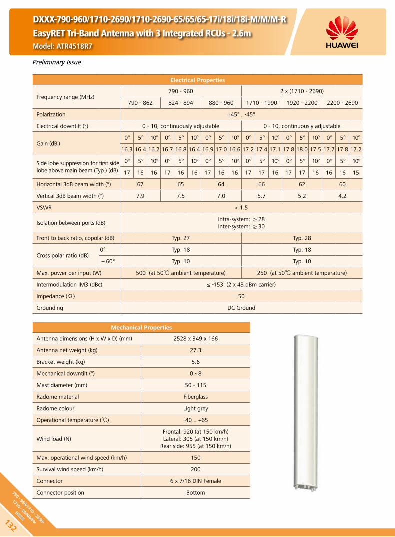
Electrical Properties
Frequency range (MHz)790 - 960 2 x (1710 - 2690)
790 - 862 824 - 894 880 - 960 1710 - 1990 1920 - 2200 2200 - 2690
Polarization +45° , -45°
Electrical downtilt (°) 0 - 10, continuously adjustable 0 - 10, continuously adjustable
Gain (dBi)0° 5° 10° 0° 5° 10° 0° 5° 10° 0° 5° 10° 0° 5° 10° 0° 5° 10°
16.3 16.4 16.2 16.7 16.8 16.4 16.9 17.0 16.6 17.2 17.4 17.1 17.8 18.0 17.5 17.7 17.8 17.2
Side lobe suppression for first side lobe above main beam (Typ.) (dB)
0° 5° 10° 0° 5° 10° 0° 5° 10° 0° 5° 10° 0° 5° 10° 0° 5° 10°
17 16 16 17 16 16 17 16 16 17 17 16 17 17 16 16 16 15
Horizontal 3dB beam width (°) 67 65 64 66 62 60
Vertical 3dB beam width (°) 7.9 7.5 7.0 5.7 5.2 4.2
VSWR < 1.5
Isolation between ports (dB)Intra-system: ≥ 28Inter-system: ≥ 30
Front to back ratio, copolar (dB) Typ. 27 Typ. 28
Cross polar ratio (dB)0° Typ. 18 Typ. 18
±60° Typ. 10 Typ. 10
Max. power per input (W) 500 (at 50 ambient temperature) 250 (at 50 ambient temperature)
Intermodulation IM3 (dBc) ≤ -153 (2 x 43 dBm carrier)
Impedance (Ω) 50
Grounding DC Ground
Mechanical Properties
Antenna dimensions (H x W x D) (mm) 2528 x 349 x 166
Antenna net weight (kg) 27.3
Bracket weight (kg) 5.6
Mechanical downtilt (°) 0 - 8
Mast diameter (mm) 50 - 115
Radome material Fiberglass
Radome colour Light grey
Operational temperature () -40 .. +65
Wind load (N)Frontal: 920 (at 150 km/h)Lateral: 305 (at 150 km/h)
Rear side: 955 (at 150 km/h)
Max. operational wind speed (km/h) 150
Survival wind speed (km/h) 200
Connector 6 x 7/16 DIN Female
Connector position Bottom
Preliminary Issue
DXXX-790-960/1710-2690/1710-2690-65/65/65-17i/18i/18i-M/M/M-REasyRET Tri-Band Antenna with 3 Integrated RCUs - 2.6mModel: ATR4518R7
132
790 - 960/1710 - 2690/
1710 - 2690MHz
DXXX
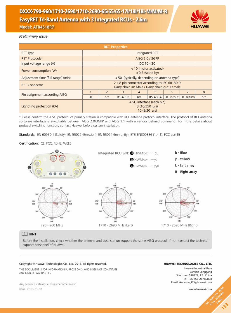
Any previous catalogue issues become invalid.
Issue: 2013-01-08
HUAWEI TECHNOLOGIES CO., LTD.
Huawei Industrial BaseBantian Longgang
Shenzhen 518129, P.R. ChinaTel: +86-755-28780808
Email: [email protected]
www.huawei.com
Copyright © Huawei Technologies Co., Ltd. 2013. All rights reserved.
THIS DOCUMENT IS FOR INFORMATION PURPOSE ONLY, AND DOSE NOT CONSTITUTE ANY KIND OF WARRANTIES.
Preliminary Issue
RET Properties
RET Type Integrated RET
RET Protocols* AISG 2.0 / 3GPP
Input voltage range (V) DC 10 - 30
Power consumption (W) < 10 (motor activated)
< 0.5 (stand by)
Adjustment time (full range) (min) < 50 (typically, depending on antenna type)
RET Connector2 x 8 pin connector according to IEC 60130-9Daisy chain in: Male / Daisy chain out: Female
Pin assignment according AISG 1 2 3 4 5 6 7 8
DC n/c RS-485B n/c RS-485A DC in/out DC return n/c
Lightning protection (kA)AISG interface (each pin)
3 (10/350 μs)10 (8/20 μs)
HINT
Before the installation, check whether the antenna and base station support the same AISG protocol. If not, contact the technical support personnel of Huawei.
* Please confirm the AISG protocol of primary station is compatible with RET antenna protocol interface. The protocol of RET antenna software interface is switchable between AISG 2.0/3GPP and AISG 1.1 with a vendor defined command. For more details about protocol switching function, contact Huawei before system installation.
Standards: EN 60950-1 (Safety), EN 55022 (Emission), EN 55024 (Immunity), ETSI EN300386 (1.4.1), FCC part15
Certification: CE, FCC, RoHS, WEEE
DXXX-790-960/1710-2690/1710-2690-65/65/65-17i/18i/18i-M/M/M-REasyRET Tri-Band Antenna with 3 Integrated RCUs - 2.6mModel: ATR4518R7
13379
0 - 9
60/1
710 - 2
690/
1710
- 26
90M
Hz
DXXX
Integrated RCU S/N: HWMxxx……bL
HWMxxx……yL
HWMxxx……yyR
a
b
c
b - Blue
y - Yellow
L - Left array
R - Right array
790 - 960 MHz 1710 - 2690 MHz (Left) 1710 - 2690 MHz (Right)

DXXX-790-960/1710-2690/1710-2690-65/65/65-15i/17.5i/17.5i-M/M/M
Model: ATR451709
Preliminary Issue
Electrical Properties
Frequency range (MHz)790 - 960 2 x (1710 - 2690)
790 - 862 824 - 894 880 - 960 1710 - 1990 1920 - 2200 2300 - 2690
Polarization +45° , -45°
Electrical downtilt (°) 0 - 14, continuously adjustable 0 - 10, continuously adjustable
Gain (dBi)0° 7° 14° 0° 7° 14° 0° 7° 14° 0° 5° 10° 0° 5° 10° 0° 5° 10°
14.2 14.0 13.6 14.4 14.2 13.8 14.6 14.4 14.0 16.7 16.9 16.5 17.3 17.5 17.0 17.2 17.4 16.7
Side lobe suppression for first side lobe above main beam (Typ.) (dB)
0° 7° 14° 0° 7° 14° 0° 7° 14° 0° 5° 10° 0° 5° 10° 0° 5° 10°
16 16 15 16 16 15 16 16 15 16 16 15 16 16 15 16 16 15
Horizontal 3dB beam width (°) 66 63 60 65 62 60
Vertical 3dB beam width (°) 15.8 15 14 6.3 5.0 4.4
VSWR < 1.5
Isolation between ports (dB)Intra-system: ≥ 28Inter-system: ≥ 30
Front to back ratio, copolar (dB) Typ. 27 Typ. 28
Cross polar ratio (dB)0° Typ. 18 Typ. 18
±60° Typ. 10 Typ. 10
Max. power per input (W) 500 (at 50 ambient temperature) 250 (at 50 ambient temperature)
Intermodulation IM3 (dBc) ≤ -153 (2 x 43 dBm carrier)
Impedance (Ω) 50
Grounding DC Ground
Mechanical Properties
Antenna dimensions (H x W x D) (mm) 1472 x 349 x 166
Antenna net weight (kg) 18
Bracket weight (kg) 4.6
Mechanical downtilt (°) 0 - 16
Mast diameter (mm) 50 - 115
Radome material Fiberglass
Radome colour Light grey
Operational temperature () -55 .. +65
Wind load (N)Frontal: 495 (at 150 km/h) Lateral: 160 (at 150 km/h)
Rear side: 525 (at 150 km/h)
Max. operational wind speed (km/h) 150
Survival wind speed (km/h) 200
Connector 6 x 7/16 DIN Female
Connector position Bottom
Any previous catalogue issues become invalid.
Issue: 2013-01-08
HUAWEI TECHNOLOGIES CO., LTD.
Huawei Industrial BaseBantian Longgang
Shenzhen 518129, P.R. ChinaTel: +86-755-28780808
Email: [email protected]
www.huawei.com
Copyright © Huawei Technologies Co., Ltd. 2013. All rights reserved.
THIS DOCUMENT IS FOR INFORMATION PURPOSE ONLY, AND DOSE NOT CONSTITUTE ANY KIND OF WARRANTIES.
134
790 - 960/1710 - 2690/
1710 - 2690MHz
DXXX

DXXX-790-960/1710-2690/1710-2690-65/65/65-16i/18i/18i-M/M/M
Model: ATR451606
Preliminary Issue
Electrical Properties
Frequency range (MHz)790 - 960 2 x (1710 - 2690)
790 - 862 824 - 894 880 - 960 1710 - 1990 1920 - 2200 2300 - 2690
Polarization +45° , -45°
Electrical downtilt (°) 0 - 10, continuously adjustable 0 - 10, continuously adjustable
Gain (dBi)0° 5° 10° 0° 5° 10° 0° 5° 10° 0° 5° 10° 0° 5° 10° 0° 5° 10°
15.7 15.8 15.4 15.8 15.9 15.5 15.8 16.0 15.5 17.2 17.4 17.1 17.8 18.0 17.5 17.7 17.8 17.2
Side lobe suppression for first side lobe above main beam (Typ.) (dB)
0° 5° 10° 0° 5° 10° 0° 5° 10° 0° 5° 10° 0° 5° 10° 0° 5° 10°
16 16 15 16 16 15 16 16 15 17 17 16 17 17 16 16 16 15
Horizontal 3dB beam width (°) 66 63 60 65 62 60
Vertical 3dB beam width (°) 9.8 9.4 8.8 5.7 5.2 4.2
VSWR < 1.5
Isolation between ports (dB)Intra-system: ≥ 28Inter-system: ≥ 30
Front to back ratio, copolar (dB) Typ. 27 Typ. 28
Cross polar ratio (dB)0° Typ. 18 Typ. 18
±60° Typ. 10 Typ. 10
Max. power per input (W) 500 (at 50 ambient temperature) 250 (at 50 ambient temperature)
Intermodulation IM3 (dBc) ≤ -153 (2 x 43 dBm carrier)
Impedance (Ω) 50
Grounding DC Ground
Mechanical Properties
Antenna dimensions (H x W x D) (mm) 1999 x 349 x 166
Antenna net weight (kg) 23
Bracket weight (kg) 4.6
Mechanical downtilt (°) 0 - 12
Mast diameter (mm) 50 - 115
Radome material Fiberglass
Radome colour Light grey
Operational temperature () -55 .. +65
Wind load (N)Frontal: 705 (at 150 km/h)Lateral: 230 (at 150 km/h)
Rear side: 745 (at 150 km/h)
Max. operational wind speed (km/h) 150
Survival wind speed (km/h) 200
Connector 6 x 7/16 DIN Female
Connector position Bottom
Any previous catalogue issues become invalid.
Issue: 2013-01-08
HUAWEI TECHNOLOGIES CO., LTD.
Huawei Industrial BaseBantian Longgang
Shenzhen 518129, P.R. ChinaTel: +86-755-28780808
Email: [email protected]
www.huawei.com
Copyright © Huawei Technologies Co., Ltd. 2013. All rights reserved.
THIS DOCUMENT IS FOR INFORMATION PURPOSE ONLY, AND DOSE NOT CONSTITUTE ANY KIND OF WARRANTIES.
13579
0 - 9
60/1
710 - 2
690/
1710
- 26
90M
Hz
DXXX

DXXX-790-960/1710-2690/1710-2690-65/65/65-17i/18i/18i-M/M/M
Model: ATR451607
Preliminary Issue
Electrical Properties
Frequency range (MHz)790 - 960 2 x (1710 - 2690)
790 - 862 824 - 894 880 - 960 1710 - 1990 1920 - 2200 2300 - 2690
Polarization +45° , -45°
Electrical downtilt (°) 0 - 10, continuously adjustable 0 - 10, continuously adjustable
Gain (dBi)0° 5° 10° 0° 5° 10° 0° 5° 10° 0° 5° 10° 0° 5° 10° 0° 5° 10°
16.3 16.4 16.2 16.7 16.8 16.4 16.9 17.0 16.6 17.2 17.4 17.1 17.8 18.0 17.5 17.7 17.8 17.2
Side lobe suppression for first side lobe above main beam (Typ.) (dB)
0° 5° 10° 0° 5° 10° 0° 5° 10° 0° 5° 10° 0° 5° 10° 0° 5° 10°
17 16 16 17 16 16 17 16 16 17 17 16 17 17 16 16 16 15
Horizontal 3dB beam width (°) 67 65 64 66 62 60
Vertical 3dB beam width (°) 7.9 7.5 7.0 5.7 5.2 4.2
VSWR < 1.5
Isolation between ports (dB)Intra-system: ≥ 28Inter-system: ≥ 30
Front to back ratio, copolar (dB) Typ. 27 Typ. 28
Cross polar ratio (dB)0° Typ. 18 Typ. 18
±60° Typ. 10 Typ. 10
Max. power per input (W) 500 (at 50 ambient temperature) 250 (at 50 ambient temperature)
Intermodulation IM3 (dBc) ≤ -153 (2 x 43 dBm carrier)
Impedance (Ω) 50
Grounding DC Ground
Mechanical Properties
Antenna dimensions (H x W x D) (mm) 2593 x 349 x 166
Antenna net weight (kg) 28
Bracket weight (kg) 5.6
Mechanical downtilt (°) 0 - 8
Mast diameter (mm) 50 - 115
Radome material Fiberglass
Radome colour Light grey
Operational temperature () -55 .. +65
Wind load (N)Frontal: 950 (at 150 km/h)Lateral: 315 (at 150 km/h)
Rear side: 985 (at 150 km/h)
Max. operational wind speed (km/h) 150
Survival wind speed (km/h) 200
Connector 6 x 7/16 DIN Female
Connector position Bottom
Any previous catalogue issues become invalid.
Issue: 2013-01-08
HUAWEI TECHNOLOGIES CO., LTD.
Huawei Industrial BaseBantian Longgang
Shenzhen 518129, P.R. ChinaTel: +86-755-28780808
Email: [email protected]
www.huawei.com
Copyright © Huawei Technologies Co., Ltd. 2013. All rights reserved.
THIS DOCUMENT IS FOR INFORMATION PURPOSE ONLY, AND DOSE NOT CONSTITUTE ANY KIND OF WARRANTIES.
136
790 - 960/1710 - 2690/
1710 - 2690MHz
DXXX

DXXX-698-960/1710-2690/1710-2690-65/65/65-17i/17.5i/17.5i-M/M/M-B\RModel: ATR4518R9
Electrical Properties
Frequency range (MHz)698 - 960 2 x (1710 - 2690)
698 - 806 790 - 894 880 - 960 1710 - 1990 1920 - 2170 2490 - 2690
Polarization +45° , -45°
Electrical downtilt (°) 0 - 10, continuously adjustable 0 - 8, continuously adjustable
Gain (dBi)0° 5° 10° 0° 5° 10° 0° 5° 10° 0° 4° 8° 0° 4° 8° 0° 4° 8°
16.2 16.4 16.1 16.6 16.8 16.4 17.1 17.2 16.8 17.4 17.6 17.4 18.3 18.3 18.0 18.2 18.3 18.0
Side lobe suppression for first side lobe above main beam (Typ.) (dB)
0° 5° 10° 0° 5° 10° 0° 5° 10° 0° 4° 8° 0° 4° 8° 0° 4° 8°
17 16 16 17 16 16 17 16 16 17 17 16 17 17 16 16 16 15
Horizontal 3dB beam width (°) 66 63 60 68 63 60
Vertical 3dB beam width (°) 8.3 7.6 7.1 5.2 4.8 4.0
VSWR < 1.5
Isolation between ports (dB)Intra-system: ≥ 28Inter-system: ≥ 30
Front to back ratio, copolar (dB) Typ. 28 Typ. 27
Cross polar ratio (dB)0° Typ. 18 Typ. 17
±60° Typ. 10 Typ. 10
Max. power per input (W) 500 (at 50 ambient temperature) 250 (at 50 ambient temperature)
Intermodulation IM3 (dBc) ≤ -153 (2 x 43 dBm carrier)
Impedance (Ω) 50
Grounding DC Ground
Mechanical Properties
Antenna dimensions (H x W x D) (mm) 2685 x 349 x 148
Antenna net weight (kg) 37
Bracket weight (kg) 5.6
Mechanical downtilt (°) 0 - 8
Mast diameter (mm) 50 - 115
Radome material Fiberglass
Radome colour Light grey
Operational temperature () -40 .. +65
Wind load (N)Frontal: 1215 (at 150 km/h)Lateral: 445 (at 150 km/h)
Rear side: 1555 (at 150 km/h)
Max. operational wind speed (km/h) 150
Survival wind speed (km/h) 200
Connector 6 x 7/16 DIN Female
Connector position Bottom
RET Type Internal motor, Internal Smart Bias-T
RET Protocols AISG 1.1 / AISG 2.0
Preliminary Issue
13769
8 - 9
60/1
710 - 2
690/
1710
- 26
90M
Hz
DXXX

DXXX-698-960/1710-2690/1710-2690-65/65/65-17i/17.5i/17.5i-M/M/M-B\RModel: ATR4518R9
RET Properties
RET Type Internal motor, Internal smart Bias-T
RET Protocols AISG 1.1 / AISG 2.0
Input voltage range (V) DC 10 - 30
Power consumption (W) < 11 (motor activated)
< 1 (stand by)
Adjustment time (full range) (min) < 1.5 (typically, depending on antenna type)
Calibration time (min) < 3 (typically, depending on antenna type)
Smart Bias-T portInternal Bias-T from +45° port (698 MHz - 960 MHz)
(2.176MHz modulated data)
Lightning protection (kA)3 (10/350 μs)10 (8/20 μs)
HINT
Before the installation, check whether the antenna and base station support the same AISG protocol. If not, contact the technical support personnel of Huawei.
Standards:
EN 60950-1 (Safety) y
EN 55022 (Emission) y
EN 55024 (Immunity) y
ETSI EN300386 (1.4.1) y
FCC part15 y
Certification:
CE, FCC, RoHS, WEEE
Any previous catalogue issues become invalid.
Issue: 2013-01-08
HUAWEI TECHNOLOGIES CO., LTD.
Huawei Industrial BaseBantian Longgang
Shenzhen 518129, P.R. ChinaTel: +86-755-28780808
Email: [email protected]
www.huawei.com
Copyright © Huawei Technologies Co., Ltd. 2013. All rights reserved.
THIS DOCUMENT IS FOR INFORMATION PURPOSE ONLY, AND DOSE NOT CONSTITUTE ANY KIND OF WARRANTIES.
Preliminary Issue
138
698 - 960/1710 - 2690/
1710 - 2690MHz
DXXX

DXXX-1710-2690/1710-2170/2490-2690-65/65/65-18i/18i/18i-M/M/M-REasyRET Tri-Band Antenna with 3 Integrated RCUs - 1.4mModel: ATR4518R3
Electrical Properties
Frequency range (MHz)1710 - 2690 1710 - 2170
2490 - 26901710 - 1990 1920 - 2200 2300 - 2690 1710 - 1990 1920 - 2170
Polarization +45° , -45°
Electrical downtilt (°) 0 - 12, continuously adjustable 0 - 12, continuously adjustable
Gain (dBi)0° 6° 12° 0° 6° 12° 0° 6° 12° 0° 6° 12° 0° 6° 12° 0° 6° 12°
17.3 17.4 17.2 17.6 17.8 17.5 17.8 18.0 17.3 17.0 17.1 16.9 17.3 17.6 17.2 17.4 17.6 16.9
Side lobe suppression (Typ.) (dB)
-for first side lobe above main beam
-within 0° - 15° sector above horizon
0° 6° 12° 0° 6° 12° 0° 6° 12° 0° 6° 12° 0° 6° 12° 0° 6° 12°
18 17 16 18 17 16 18 17 16 17 16 15 17 16 15 17 16 15
16 16 15 16 16 15 15 16 15 16 16 15 16 16 15 15 16 15
Horizontal 3dB beam width (°) 66 63 60 66 63 60
Vertical 3dB beam width (°) 6.5 6.0 4.8 6.5 6.0 4.8
VSWR < 1.5
Isolation between ports (dB)Intra-system: ≥ 30Inter-system: ≥ 30
Front to back ratio, copolar (dB) Typ. 28
Cross polar ratio (dB)0° Typ. 18
±60° Typ. 10
Max. power per input (W) 250 (at 50 ambient temperature)
Intermodulation IM3 (dBc) ≤ -153 (2 x 43 dBm carrier)
Impedance (Ω) 50
Grounding DC Ground
Mechanical Properties
Antenna dimensions (H x W x D) (mm) 1445 x 299 x 109
Antenna net weight (kg) 15.8
Bracket weight (kg) 4.6
Mechanical downtilt (°) 0 - 16
Mast diameter (mm) 50 - 115
Radome material Fiberglass
Radome colour Light grey
Operational temperature () -40 .. +65
Wind load (N)Frontal: 520 (at 150 km/h)Lateral: 105 (at 150 km/h)
Rear side: 600 (at 150 km/h)
Max. operational wind speed (km/h) 150
Survival wind speed (km/h) 200
Connector 6 x 7/16 DIN Female
Connector position Bottom
Preliminary Issue
13917
10 - 26
90/1
710 - 2
170/
2490
- 26
90M
Hz
DXXX

DXXX-1710-2690/1710-2170/2490-2690-65/65/65-18i/18i/18i-M/M/M-REasyRET Tri-Band Antenna with 3 Integrated RCUs - 1.4mModel: ATR4518R3
Any previous catalogue issues become invalid.
Issue: 2013-01-08
HUAWEI TECHNOLOGIES CO., LTD.
Huawei Industrial BaseBantian Longgang
Shenzhen 518129, P.R. ChinaTel: +86-755-28780808
Email: [email protected]
www.huawei.com
Copyright © Huawei Technologies Co., Ltd. 2013. All rights reserved.
THIS DOCUMENT IS FOR INFORMATION PURPOSE ONLY, AND DOSE NOT CONSTITUTE ANY KIND OF WARRANTIES.
Preliminary Issue
RET Properties
RET Type Integrated RET
RET Protocols* AISG 2.0 / 3GPP
Input voltage range (V) DC 10 - 30
Power consumption (W) < 10 (motor activated)
< 0.5 (stand by)
Adjustment time (full range) (min) < 50 (typically, depending on antenna type)
RET Connector2 x 8 pin connector according to IEC 60130-9Daisy chain in: Male / Daisy chain out: Female
Pin assignment according AISG 1 2 3 4 5 6 7 8
DC n/c RS-485B n/c RS-485A DC in/out DC return n/c
Lightning protection (kA)AISG interface (each pin)
3 (10/350 μs)10 (8/20 μs)
HINT
Before the installation, check whether the antenna and base station support the same AISG protocol. If not, contact the technical support personnel of Huawei.
* Please confirm the AISG protocol of primary station is compatible with RET antenna protocol interface. The protocol of RET antenna software interface is switchable between AISG 2.0/3GPP and AISG 1.1 with a vendor defined command. For more details about protocol switching function, contact Huawei before system installation.
Standards: EN 60950-1 (Safety), EN 55022 (Emission), EN 55024 (Immunity), ETSI EN300386 (1.4.1), FCC part15
Certification: CE, FCC, RoHS, WEEE
Integrated RCU S/N: HWMxxx……bL
HWMxxx……yL
HWMxxx……yyR
a
b
c
b - Blue
y - Yellow
L - Left array
R - Right array
140
1710 - 2690/1710 - 2170/
2490 - 2690MHz
DXXX
1710 - 2690 MHz 1710 - 2170 MHz 2490 - 2690 MHz
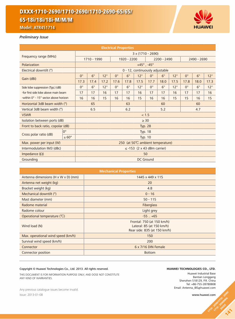
Mechanical Properties
Antenna dimensions (H x W x D) (mm) 1445 x 449 x 115
Antenna net weight (kg) 20
Bracket weight (kg) 4.8
Mechanical downtilt (°) 0 - 16
Mast diameter (mm) 50 - 115
Radome material Fiberglass
Radome colour Light grey
Operational temperature () -55 .. +65
Wind load (N)Frontal: 750 (at 150 km/h) Lateral: 85 (at 150 km/h)
Rear side: 835 (at 150 km/h)
Max. operational wind speed (km/h) 150
Survival wind speed (km/h) 200
Connector 6 x 7/16 DIN Female
Connector position Bottom
Any previous catalogue issues become invalid.
Issue: 2013-01-08
HUAWEI TECHNOLOGIES CO., LTD.
Huawei Industrial BaseBantian Longgang
Shenzhen 518129, P.R. ChinaTel: +86-755-28780808
Email: [email protected]
www.huawei.com
Copyright © Huawei Technologies Co., Ltd. 2013. All rights reserved.
THIS DOCUMENT IS FOR INFORMATION PURPOSE ONLY, AND DOSE NOT CONSTITUTE ANY KIND OF WARRANTIES.
Preliminary Issue
Electrical Properties
Frequency range (MHz)3 x (1710 - 2690)
1710 - 1990 1920 - 2200 2200 - 2490 2490 - 2690
Polarization +45° , -45°
Electrical downtilt (°) 0 - 12, continuously adjustable
Gain (dBi)0° 6° 12° 0° 6° 12° 0° 6° 12° 0° 6° 12°
17.3 17.4 17.2 17.6 17.8 17.5 17.7 18.0 17.5 17.8 18.0 17.3
Side lobe suppression (Typ.) (dB)
-for first side lobe above main beam
-within 0° - 15° sector above horizon
0° 6° 12° 0° 6° 12° 0° 6° 12° 0° 6° 12°
17 17 16 17 17 16 17 17 16 17 17 16
16 16 15 16 16 15 16 16 15 15 16 15
Horizontal 3dB beam width (°) 65 63 60 60
Vertical 3dB beam width (°) 6.5 6.2 5.2 4.7
VSWR < 1.5
Isolation between ports (dB) ≥ 30
Front to back ratio, copolar (dB) Typ. 28
Cross polar ratio (dB)0° Typ. 18
±60° Typ. 10
Max. power per input (W) 250 (at 50 ambient temperature)
Intermodulation IM3 (dBc) ≤ -153 (2 x 43 dBm carrier)
Impedance (Ω) 50
Grounding DC Ground
DXXX-1710-2690/1710-2690/1710-2690-65/65/65-18i/18i/18i-M/M/MModel: ATR451714
14117
10 - 26
90/1
710 - 2
690/
1710
- 26
90M
Hz
DXXX
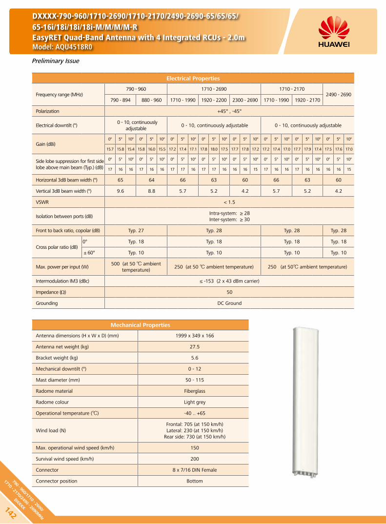
Preliminary Issue
Electrical Properties
Frequency range (MHz)790 - 960 1710 - 2690 1710 - 2170
2490 - 2690790 - 894 880 - 960 1710 - 1990 1920 - 2200 2300 - 2690 1710 - 1990 1920 - 2170
Polarization +45° , -45°
Electrical downtilt (°) 0 - 10, continuously
adjustable 0 - 10, continuously adjustable 0 - 10, continuously adjustable
Gain (dBi)0° 5° 10° 0° 5° 10° 0° 5° 10° 0° 5° 10° 0° 5° 10° 0° 5° 10° 0° 5° 10° 0° 5° 10°
15.7 15.8 15.4 15.8 16.0 15.5 17.2 17.4 17.1 17.8 18.0 17.5 17.7 17.8 17.2 17.2 17.4 17.0 17.7 17.9 17.4 17.5 17.6 17.0
Side lobe suppression for first side lobe above main beam (Typ.) (dB)
0° 5° 10° 0° 5° 10° 0° 5° 10° 0° 5° 10° 0° 5° 10° 0° 5° 10° 0° 5° 10° 0° 5° 10°
17 16 16 17 16 16 17 17 16 17 17 16 16 16 15 17 16 16 17 16 16 16 16 15
Horizontal 3dB beam width (°) 65 64 66 63 60 66 63 60
Vertical 3dB beam width (°) 9.6 8.8 5.7 5.2 4.2 5.7 5.2 4.2
VSWR < 1.5
Isolation between ports (dB)Intra-system: ≥ 28Inter-system: ≥ 30
Front to back ratio, copolar (dB) Typ. 27 Typ. 28 Typ. 28 Typ. 28
Cross polar ratio (dB)0° Typ. 18 Typ. 18 Typ. 18 Typ. 18
±60° Typ. 10 Typ. 10 Typ. 10 Typ. 10
Max. power per input (W)500 (at 50 ambient
temperature)250 (at 50 ambient temperature) 250 (at 50 ambient temperature)
Intermodulation IM3 (dBc) ≤ -153 (2 x 43 dBm carrier)
Impedance (Ω) 50
Grounding DC Ground
Mechanical Properties
Antenna dimensions (H x W x D) (mm) 1999 x 349 x 166
Antenna net weight (kg) 27.5
Bracket weight (kg) 5.6
Mechanical downtilt (°) 0 - 12
Mast diameter (mm) 50 - 115
Radome material Fiberglass
Radome colour Light grey
Operational temperature () -40 .. +65
Wind load (N)Frontal: 705 (at 150 km/h)Lateral: 230 (at 150 km/h)
Rear side: 730 (at 150 km/h)
Max. operational wind speed (km/h) 150
Survival wind speed (km/h) 200
Connector 8 x 7/16 DIN Female
Connector position Bottom
DXXXX-790-960/1710-2690/1710-2170/2490-2690-65/65/65/65-16i/18i/18i/18i-M/M/M/M-REasyRET Quad-Band Antenna with 4 Integrated RCUs - 2.0mModel: AQU4518R0
142
790 - 960/1710 - 2690/
1710 - 2170/2490 - 2690MHz
DXXXX
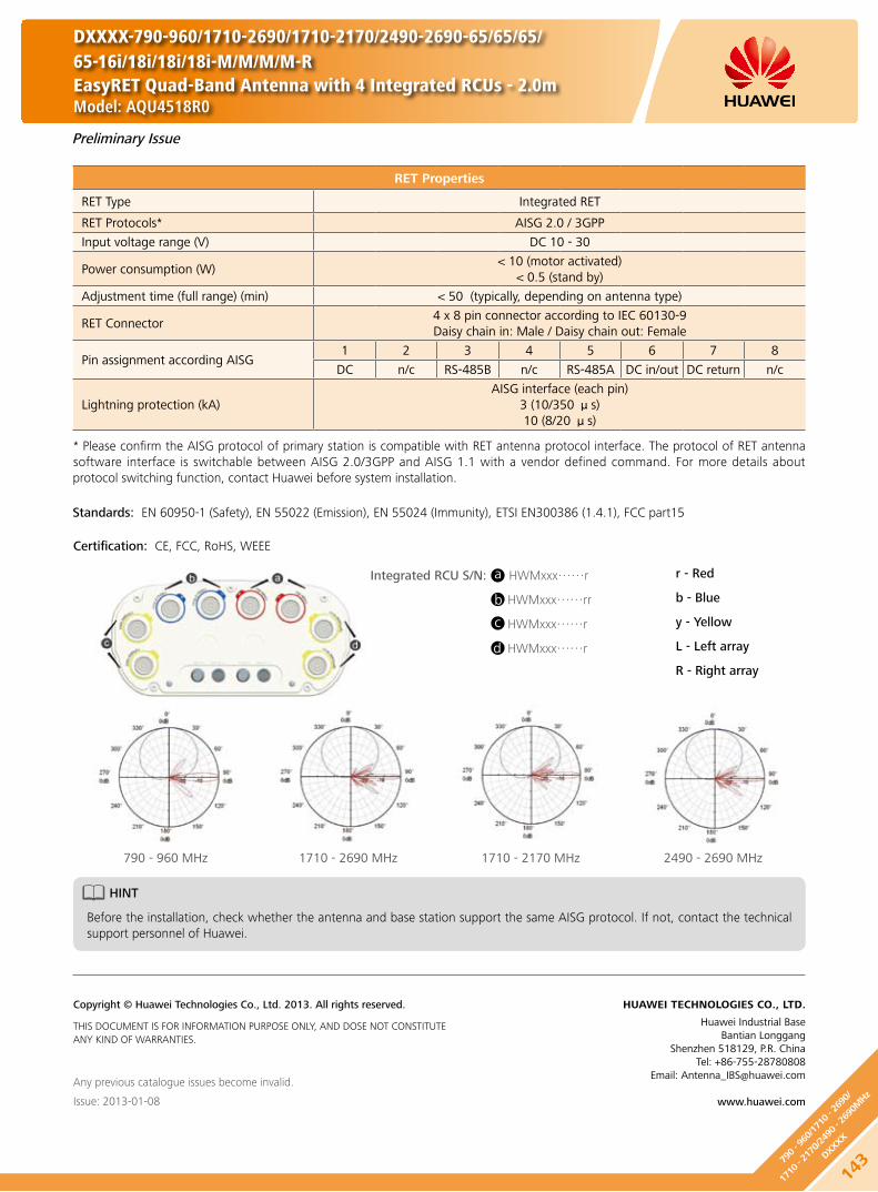
Preliminary Issue
Any previous catalogue issues become invalid.
Issue: 2013-01-08
HUAWEI TECHNOLOGIES CO., LTD.
Huawei Industrial BaseBantian Longgang
Shenzhen 518129, P.R. ChinaTel: +86-755-28780808
Email: [email protected]
www.huawei.com
Copyright © Huawei Technologies Co., Ltd. 2013. All rights reserved.
THIS DOCUMENT IS FOR INFORMATION PURPOSE ONLY, AND DOSE NOT CONSTITUTE ANY KIND OF WARRANTIES.
RET Properties
RET Type Integrated RET
RET Protocols* AISG 2.0 / 3GPP
Input voltage range (V) DC 10 - 30
Power consumption (W) < 10 (motor activated)
< 0.5 (stand by)
Adjustment time (full range) (min) < 50 (typically, depending on antenna type)
RET Connector4 x 8 pin connector according to IEC 60130-9Daisy chain in: Male / Daisy chain out: Female
Pin assignment according AISG 1 2 3 4 5 6 7 8
DC n/c RS-485B n/c RS-485A DC in/out DC return n/c
Lightning protection (kA)AISG interface (each pin)
3 (10/350 μs)10 (8/20 μs)
HINT
Before the installation, check whether the antenna and base station support the same AISG protocol. If not, contact the technical support personnel of Huawei.
* Please confirm the AISG protocol of primary station is compatible with RET antenna protocol interface. The protocol of RET antenna software interface is switchable between AISG 2.0/3GPP and AISG 1.1 with a vendor defined command. For more details about protocol switching function, contact Huawei before system installation.
Standards: EN 60950-1 (Safety), EN 55022 (Emission), EN 55024 (Immunity), ETSI EN300386 (1.4.1), FCC part15
Certification: CE, FCC, RoHS, WEEE
DXXXX-790-960/1710-2690/1710-2170/2490-2690-65/65/65/65-16i/18i/18i/18i-M/M/M/M-REasyRET Quad-Band Antenna with 4 Integrated RCUs - 2.0mModel: AQU4518R0
Integrated RCU S/N: HWMxxx……r
HWMxxx……rr
HWMxxx……r
HWMxxx……r
a
b
c
d
r - Red
b - Blue
y - Yellow
L - Left array
R - Right array
14379
0 - 9
60/1
710 - 2
690/
1710
- 21
70/2
490 - 2
690M
Hz
DXXXX
790 - 960 MHz 1710 - 2690 MHz 1710 - 2170 MHz 2490 - 2690 MHz

Preliminary Issue
Electrical Properties
Frequency range (MHz)790 - 960 1710 - 2690 1710 - 2170
2490 - 2690790 - 894 880 - 960 1710 - 1990 1920 - 2200 2300 - 2690 1710 - 1990 1920 - 2170
Polarization +45° , -45°
Electrical downtilt (°) 0 - 10, continuously
adjustable 0 - 10, continuously adjustable 0 - 10, continuously adjustable
Gain (dBi)0° 5° 10° 0° 5° 10° 0° 5° 10° 0° 5° 10° 0° 5° 10° 0° 5° 10° 0° 5° 10° 0° 5° 10°
16.7 16.6 16.3 16.9 17.0 16.6 17.2 17.4 17.1 17.8 18.0 17.5 17.7 17.7 17.2 17.2 17.2 17.0 17.7 17.9 17.4 17.5 17.6 17.0
Side lobe suppression for first side lobe above main beam (Typ.) (dB)
0° 5° 10° 0° 5° 10° 0° 5° 10° 0° 5° 10° 0° 5° 10° 0° 5° 10° 0° 5° 10° 0° 5° 10°
17 16 16 17 16 16 17 17 16 17 17 16 16 16 15 17 16 16 17 16 16 16 16 15
Horizontal 3dB beam width (°) 65 64 66 63 60 66 63 60
Vertical 3dB beam width (°) 8.2 7.3 5.7 5.2 4.2 5.7 5.2 4.2
VSWR < 1.5
Isolation between ports (dB)Intra-system: ≥ 28Inter-system: ≥ 30
Front to back ratio, copolar (dB) Typ. 27 Typ. 28 Typ. 28 Typ. 28
Cross polar ratio (dB)0° Typ. 18 Typ. 18 Typ. 18 Typ. 18
±60° Typ. 10 Typ. 10 Typ. 10 Typ. 10
Max. power per input (W)500 (at 50 ambient
temperature)250 (at 50 ambient temperature) 250 (at 50 ambient temperature)
Intermodulation IM3 (dBc) ≤ -153 (2 x 43 dBm carrier)
Impedance (Ω) 50
Grounding DC Ground
Mechanical Properties
Antenna dimensions (H x W x D) (mm) 2593 x 349 x 166
Antenna net weight (kg) 39
Bracket weight (kg) 5.6
Mechanical downtilt (°) 0 - 8
Mast diameter (mm) 50 - 115
Radome material Fiberglass
Radome colour Light grey
Operational temperature () -40 .. +65
Wind load (N)Frontal: 950 (at 150 km/h)Lateral: 315 (at 150 km/h)
Rear side: 985 (at 150 km/h)
Max. operational wind speed (km/h) 150
Survival wind speed (km/h) 200
Connector 8 x 7/16 DIN Female
Connector position Bottom
DXXXX-790-960/1710-2690/1710-2170/2490-2690-65/65/65/65-17i/18i/18i/18i-M/M/M/M-REasyRET Quad-Band Antenna with 4 Integrated RCUs - 2.6mModel: AQU4518R1
144
790 - 960/1710 - 2690/
1710 - 2170/2490 - 2690MHz
DXXXX
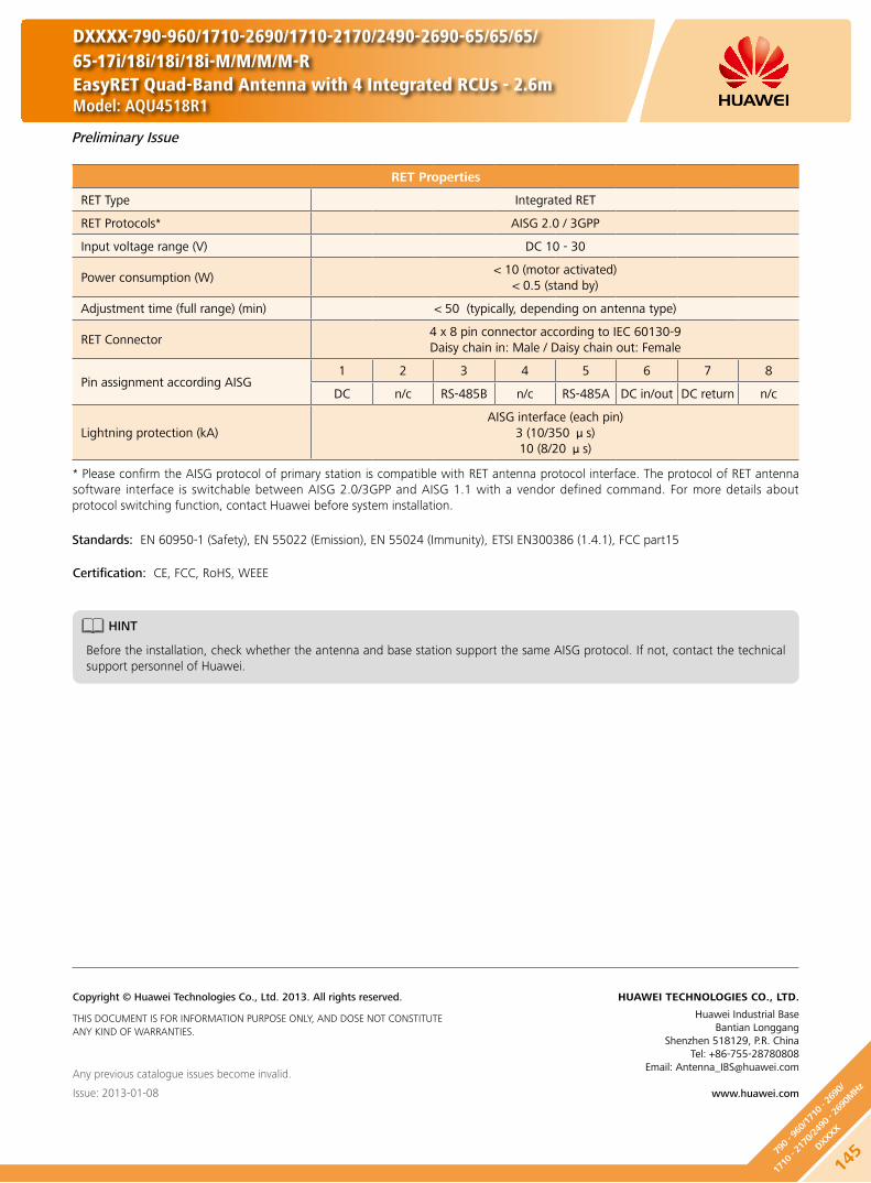
Preliminary Issue
Any previous catalogue issues become invalid.
Issue: 2013-01-08
HUAWEI TECHNOLOGIES CO., LTD.
Huawei Industrial BaseBantian Longgang
Shenzhen 518129, P.R. ChinaTel: +86-755-28780808
Email: [email protected]
www.huawei.com
Copyright © Huawei Technologies Co., Ltd. 2013. All rights reserved.
THIS DOCUMENT IS FOR INFORMATION PURPOSE ONLY, AND DOSE NOT CONSTITUTE ANY KIND OF WARRANTIES.
RET Properties
RET Type Integrated RET
RET Protocols* AISG 2.0 / 3GPP
Input voltage range (V) DC 10 - 30
Power consumption (W) < 10 (motor activated)
< 0.5 (stand by)
Adjustment time (full range) (min) < 50 (typically, depending on antenna type)
RET Connector4 x 8 pin connector according to IEC 60130-9Daisy chain in: Male / Daisy chain out: Female
Pin assignment according AISG 1 2 3 4 5 6 7 8
DC n/c RS-485B n/c RS-485A DC in/out DC return n/c
Lightning protection (kA)AISG interface (each pin)
3 (10/350 μs)10 (8/20 μs)
HINT
Before the installation, check whether the antenna and base station support the same AISG protocol. If not, contact the technical support personnel of Huawei.
* Please confirm the AISG protocol of primary station is compatible with RET antenna protocol interface. The protocol of RET antenna software interface is switchable between AISG 2.0/3GPP and AISG 1.1 with a vendor defined command. For more details about protocol switching function, contact Huawei before system installation.
Standards: EN 60950-1 (Safety), EN 55022 (Emission), EN 55024 (Immunity), ETSI EN300386 (1.4.1), FCC part15
Certification: CE, FCC, RoHS, WEEE
DXXXX-790-960/1710-2690/1710-2170/2490-2690-65/65/65/65-17i/18i/18i/18i-M/M/M/M-REasyRET Quad-Band Antenna with 4 Integrated RCUs - 2.6mModel: AQU4518R1
14579
0 - 9
60/1
710 - 2
690/
1710
- 21
70/2
490 - 2
690M
Hz
DXXXX

Electrical Properties
Frequency range (MHz)698 - 960 4 x (1710 - 2690)
698 - 806 824 - 894 880 - 960 1710 - 1990 1920 - 2170 2490 - 2690
Polarization +45° , -45°
Electrical downtilt (°) 0 - 10, continuously adjustable 0 - 10, continuously adjustable
Gain (dBi)
0° 5° 10° 0° 5° 10° 0° 5° 10° 0° 5° 10° 0° 5° 10° 0° 5° 10°
16.1 16.3 16.0 16.6 16.8 16.4 17.0 17.1 16.5
Bottom 16.2 16.3 16.0 16.8 17.1 16.4 16.5 16.8 16.2
Top 15.9 16.1 15.7 16.4 16.9 16.0 16.2 16.4 15.8
Side lobe suppression for first side lobe above main beam (Typ.) (dB)
0° 5° 10° 0° 5° 10° 0° 5° 10° 0° 5° 10° 0° 5° 10° 0° 5° 10°
17 16 16 17 16 16 17 16 16 17 17 16 17 17 16 16 16 15
Horizontal 3dB beam width (°) 67 64 62 68 63 60
Vertical 3dB beam width (°) 8.4 8.0 7.4 7.0 6.1 5.4
VSWR < 1.5
Isolation between ports (dB)Intra-system: ≥ 28Inter-system: ≥ 30
Front to back ratio, copolar (dB) Typ. 28 Typ. 27
Cross polar ratio (dB)0° Typ. 18 Typ. 18
±60° Typ. 10 Typ. 10
Max. power per input (W) 500 (at 50 ambient temperature) 250 (at 50 ambient temperature)
Intermodulation IM3 (dBc) ≤ -153 (2 x 43 dBm carrier)
Impedance (Ω) 50
Grounding DC Ground
Mechanical Properties
Antenna dimensions (H x W x D) (mm) 2695 x 349 x 166
Antenna net weight (kg) 39
Bracket weight (kg) 5.6
Mechanical downtilt (°) 0 - 8
Mast diameter (mm) 50 - 115
Radome material Fiberglass
Radome colour Light grey
Operational temperature () -40 .. +65
Wind load (N) Frontal: 1000 (at 150 km/h) Lateral: 450 (at 150 km/h)
Rear side: 970 (at 150 km/h)
Max. operational wind speed (km/h) 150
Survival wind speed (km/h) 200
Connector 10 x 7/16 DIN Female
Connector position Bottom
RET Type Internal motor, Internal Smart Bias-T
RET Protocols AISG 1.1 / AISG 2.0
Preliminary Issue
DXXXXX-698-960/1710-2690/1710-2690/1710-2690/1710-2690-65/65/65/65/65-17i/17.5i/17.5i/17i/17i-M/M/M/M/M-B\RModel: APE4517R2
146
698 - 960/1710 - 2690/1710 - 2690/
1710 - 2690/1710 - 2690MHz
DXXXXX

RET Properties
RET Type Internal motor, Internal smart Bias-T
RET Protocols AISG 1.1 / AISG 2.0
Input voltage range (V) DC 10 - 30
Power consumption (W) < 11 (motor activated)
< 1 (stand by)
Adjustment time (full range) (min) < 1.5 (typically, depending on antenna type)
Calibration time (min) < 3 (typically, depending on antenna type)
Smart Bias-T portInternal Bias-T from +45° port (698 MHz - 960 MHz)
(2.176MHz modulated data)
Lightning protection (kA)3 (10/350 μs)10 (8/20 μs)
HINT
Before the installation, check whether the antenna and base station support the same AISG protocol. If not, contact the technical support personnel of Huawei.
Standards:
EN 60950-1 (Safety) y
EN 55022 (Emission) y
EN 55024 (Immunity) y
ETSI EN300386 (1.4.1) y
FCC part15 y
Certification:
CE, FCC, RoHS, WEEE
Any previous catalogue issues become invalid.
Issue: 2013-01-08
HUAWEI TECHNOLOGIES CO., LTD.
Huawei Industrial BaseBantian Longgang
Shenzhen 518129, P.R. ChinaTel: +86-755-28780808
Email: [email protected]
www.huawei.com
Copyright © Huawei Technologies Co., Ltd. 2013. All rights reserved.
THIS DOCUMENT IS FOR INFORMATION PURPOSE ONLY, AND DOSE NOT CONSTITUTE ANY KIND OF WARRANTIES.
DXXXXX-698-960/1710-2690/1710-2690/1710-2690/1710-2690-65/65/65/65/65-17i/17.5i/17.5i/17i/17i-M/M/M/M/M-B\RModel: APE4517R2
Preliminary Issue
147
698 - 9
60/1
710 - 2
690/
1710
- 26
90/
1710
- 26
90/1
710 - 2
690M
Hz
DXXXXX

Electrical Properties
General parameters
Frequency range (MHz) 1880 - 1920 (F) 2010 - 2025 (A) 2500 - 2690 (D)
Polarization +45° , -45°
Electrical downtilt (°) 0 0 0
Electrical downtilt tolerance (°) ±1 ±1 ±1
Calibration and electrical parameters
Coupling factor between calibration port and each antenna port (dB)
-26 ±2 -26 ±2 -26 ±2
Max. amplitude tolerance from calibration port to input ports (dB)
< 0.7 < 0.7 < 0.7
Max. phase tolerance from calibration port to input ports (°)
< 5 < 5 < 5
Ports VSWR < 1.5 < 1.5 < 1.5
Co-polarization isolation between ports (dB) ≥ 20
Cross-polarization isolation between ports (dB) ≥ 25
Radiation parameters
Single column beam
Horizontal 3dB beam width (°) 100 ±15 90 ±15 65 ±10
Gain (dBi) ≥ 14.0 ≥ 15.0 ≥ 16.5
Vertical 3dB beam width (°) / / ≥ 5
Cross polar ratio (0°) (dB) ≥ 17 ≥ 17 ≥ 16
Cross polar ratio (±60°) (dB) ≥ 10 ≥ 10 ≥ 10
Front to back ratio (dB) ≥ 23 ≥ 23 ≥ 25
Vertical side lobe suppression for first side lobe above main beam (dB)
/ / ≤ -16
65° Broadcast beam
Horizontal 3dB beam width (°) 65 ±5 65 ±5 65 ±5
Gain (dBi) ≥ 14.0 ≥ 14.5 ≥ 15.2
Gain roll-off at sector edge (dB) 12 ±2 12 ±2 12 ±2
Vertical 3dB beam width (°) ≥ 7.0 ≥ 6.5 ≥ 5.0
Cross polar ratio (0°) (dB) ≥ 18 ≥ 18 ≥ 18
Cross polar ratio (±60°) (dB) ≥ 10 ≥ 10 ≥ 10
Front to back ratio (dB) ≥ 28 ≥ 28 ≥ 28
Vertical side lobe suppression for first side lobe above main beam (dB)
≤ -16 ≤ -16 ≤ -16
Null fill at first null point below main beam (dB)
Typ. -18 Typ. -18 Typ. -18
Service beam
0° direct beam gain (dBi) ≥ 20.0 ≥ 20.5 ≥ 22.0
0° direct beam horizontal 3dB beam width (°)
≤ 29 ≤ 26 ≤ 21
0° direct beam side lobe suppression (dB) ≤ -12 ≤ -12 ≤ -12
±60° direct beam gain (dBi) ≥ 17.5 ≥ 17.5 ≥ 19.5
±60° direct beam horizontal 3dB beam width (°)
≤ 35 ≤ 32 ≤ 25
±60° direct beam horizontal side lobe suppression (dB)
≤ -5 ≤ -5 ≤ -4
0° direct beam cross polar ratio (0°) (dB) ≥ 20 ≥ 20 ≥ 20
0° direct beam front to back ratio (dB) ≥ 28 ≥ 28 ≥ 28
DX4-1880-2690-90-16i-0F
Model: ATD451600
Preliminary Issue
148
1880 - 2690MHz
DX4

Electrical Properties
Distance between columns (mm) 75
Antenna dimensions (H x W x D) (mm) 1396 x 319 x 116
Antenna net weight (kg) 13.0
Bracket weight (kg) 4.6
Mechanical downtilt (°) -5 - 10
Mast diameter (mm) 50 - 115
Radome material UPVC
Radome colour Light grey
Operational temperature () -55 .. +65
Wind load (N)Frontal: 620 (at 150 km/h)Lateral: 160 (at 150 km/h)
Rear side: 680 (at 150 km/h)
Max. operational wind speed (km/h) 150
Survival wind speed (km/h) 200
Connector 9 x N Female
Connector position Bottom
Any previous catalogue issues become invalid.
Issue: 2013-01-08
HUAWEI TECHNOLOGIES CO., LTD.
Huawei Industrial BaseBantian Longgang
Shenzhen 518129, P.R. ChinaTel: +86-755-28780808
Email: [email protected]
www.huawei.com
Copyright © Huawei Technologies Co., Ltd. 2013. All rights reserved.
THIS DOCUMENT IS FOR INFORMATION PURPOSE ONLY, AND DOSE NOT CONSTITUTE ANY KIND OF WARRANTIES.
DX4-1880-2690-90-16i-0F
Model: ATD451600
Preliminary Issue
14918
80 -
2690
MHz
DX4

Electrical Properties
General parameters
Frequency range (MHz) 1880 - 1920 (F) 2010 - 2025 (A) 2500 - 2690 (D)
Polarization +45° , -45°
Electrical downtilt (°) 3 3 3
Electrical downtilt tolerance (°) ±1 ±1 ±1
Calibration and electrical parameters
Coupling factor between calibration port and each antenna port (dB)
-26 ±2 -26 ±2 -26 ±2
Max. amplitude tolerance from calibration port to input ports (dB)
< 0.7 < 0.7 < 0.7
Max. phase tolerance from calibration port to input ports (°)
< 5 < 5 < 5
Ports VSWR < 1.5 < 1.5 < 1.5
Co-polarization isolation between ports (dB) ≥ 25
Cross-polarization isolation between ports (dB) ≥ 28
Radiation parameters
Single column beam
Horizontal 3dB beam width (°) 100 ±15 90 ±15 65 ±10
Gain (dBi) ≥ 14.0 ≥ 15.0 ≥ 16.5
Vertical 3dB beam width (°) / / ≥ 5
Cross polar ratio (0°) (dB) ≥ 17 ≥ 17 ≥ 16
Cross polar ratio (±60°) (dB) ≥ 10 ≥ 10 ≥ 10
Front to back ratio (dB) ≥ 23 ≥ 23 ≥ 25
Vertical side lobe suppression for first side lobe above main beam (dB)
/ / ≤ -16
65° Broadcast beam
Horizontal 3dB beam width (°) 65 ±5 65 ±5 65 ±5
Gain (dBi) ≥ 14.0 ≥ 14.5 ≥ 15.2
Gain roll-off at sector edge (dB) 12 ±2 12 ±2 12 ±2
Vertical 3dB beam width (°) ≥ 7.0 ≥ 6.5 ≥ 5.0
Cross polar ratio (0°) (dB) ≥ 18 ≥ 18 ≥ 18
Cross polar ratio (±60°) (dB) ≥ 10 ≥ 10 ≥ 10
Front to back ratio (dB) ≥ 28 ≥ 28 ≥ 28
Vertical side lobe suppression for first side lobe above main beam (dB)
≤ -16 ≤ -16 ≤ -16
Null fill at first null point below main beam (dB)
Typ. -18 Typ. -18 Typ. -18
Service beam
0° direct beam gain (dBi) ≥ 20.0 ≥ 20.5 ≥ 22.0
0° direct beam horizontal 3dB beam width (°)
≤ 29 ≤ 26 ≤ 21
0° direct beam side lobe suppression (dB) ≤ -12 ≤ -12 ≤ -12
±60° direct beam gain (dBi) ≥ 17.5 ≥ 17.5 ≥ 19.5
±60° direct beam horizontal 3dB beam width (°)
≤ 35 ≤ 32 ≤ 25
±60° direct beam horizontal side lobe suppression (dB)
≤ -5 ≤ -5 ≤ -4
0° direct beam cross polar ratio (0°) (dB) ≥ 20 ≥ 20 ≥ 20
0° direct beam front to back ratio (dB) ≥ 28 ≥ 28 ≥ 28
DX4-1880-2690-90-16i-3F
Model: ATD451601
Preliminary Issue
150
1880 - 2690MHz
DX4

Electrical Properties
Distance between columns (mm) 75
Antenna dimensions (H x W x D) (mm) 1396 x 319 x 116
Antenna net weight (kg) 13.0
Bracket weight (kg) 4.6
Mechanical downtilt (°) -5 - 10
Mast diameter (mm) 50 - 115
Radome material UPVC
Radome colour Light grey
Operational temperature () -55 .. +65
Wind load (N)Frontal: 620 (at 150 km/h)Lateral: 160 (at 150 km/h)
Rear side: 680 (at 150 km/h)
Max. operational wind speed (km/h) 150
Survival wind speed (km/h) 200
Connector 9 x N Female
Connector position Bottom
Any previous catalogue issues become invalid.
Issue: 2013-01-08
HUAWEI TECHNOLOGIES CO., LTD.
Huawei Industrial BaseBantian Longgang
Shenzhen 518129, P.R. ChinaTel: +86-755-28780808
Email: [email protected]
www.huawei.com
Copyright © Huawei Technologies Co., Ltd. 2013. All rights reserved.
THIS DOCUMENT IS FOR INFORMATION PURPOSE ONLY, AND DOSE NOT CONSTITUTE ANY KIND OF WARRANTIES.
DX4-1880-2690-90-16i-3F
Model: ATD451601
Preliminary Issue
15118
80 -
2690
MHz
DX4
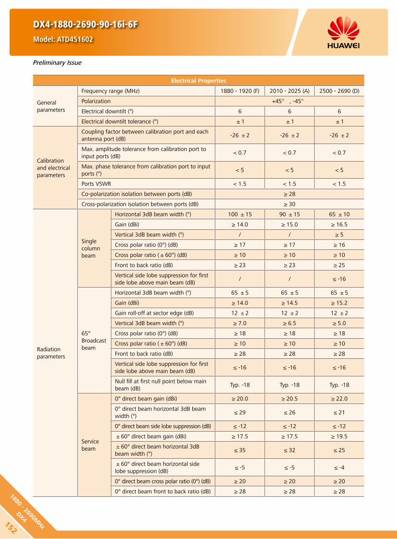
Electrical Properties
General parameters
Frequency range (MHz) 1880 - 1920 (F) 2010 - 2025 (A) 2500 - 2690 (D)
Polarization +45° , -45°
Electrical downtilt (°) 6 6 6
Electrical downtilt tolerance (°) ±1 ±1 ±1
Calibration and electrical parameters
Coupling factor between calibration port and each antenna port (dB)
-26 ±2 -26 ±2 -26 ±2
Max. amplitude tolerance from calibration port to input ports (dB)
< 0.7 < 0.7 < 0.7
Max. phase tolerance from calibration port to input ports (°)
< 5 < 5 < 5
Ports VSWR < 1.5 < 1.5 < 1.5
Co-polarization isolation between ports (dB) ≥ 28
Cross-polarization isolation between ports (dB) ≥ 30
Radiation parameters
Single column beam
Horizontal 3dB beam width (°) 100 ±15 90 ±15 65 ±10
Gain (dBi) ≥ 14.0 ≥ 15.0 ≥ 16.5
Vertical 3dB beam width (°) / / ≥ 5
Cross polar ratio (0°) (dB) ≥ 17 ≥ 17 ≥ 16
Cross polar ratio (±60°) (dB) ≥ 10 ≥ 10 ≥ 10
Front to back ratio (dB) ≥ 23 ≥ 23 ≥ 25
Vertical side lobe suppression for first side lobe above main beam (dB)
/ / ≤ -16
65° Broadcast beam
Horizontal 3dB beam width (°) 65 ±5 65 ±5 65 ±5
Gain (dBi) ≥ 14.0 ≥ 14.5 ≥ 15.2
Gain roll-off at sector edge (dB) 12 ±2 12 ±2 12 ±2
Vertical 3dB beam width (°) ≥ 7.0 ≥ 6.5 ≥ 5.0
Cross polar ratio (0°) (dB) ≥ 18 ≥ 18 ≥ 18
Cross polar ratio (±60°) (dB) ≥ 10 ≥ 10 ≥ 10
Front to back ratio (dB) ≥ 28 ≥ 28 ≥ 28
Vertical side lobe suppression for first side lobe above main beam (dB)
≤ -16 ≤ -16 ≤ -16
Null fill at first null point below main beam (dB)
Typ. -18 Typ. -18 Typ. -18
Service beam
0° direct beam gain (dBi) ≥ 20.0 ≥ 20.5 ≥ 22.0
0° direct beam horizontal 3dB beam width (°)
≤ 29 ≤ 26 ≤ 21
0° direct beam side lobe suppression (dB) ≤ -12 ≤ -12 ≤ -12
±60° direct beam gain (dBi) ≥ 17.5 ≥ 17.5 ≥ 19.5
±60° direct beam horizontal 3dB beam width (°)
≤ 35 ≤ 32 ≤ 25
±60° direct beam horizontal side lobe suppression (dB)
≤ -5 ≤ -5 ≤ -4
0° direct beam cross polar ratio (0°) (dB) ≥ 20 ≥ 20 ≥ 20
0° direct beam front to back ratio (dB) ≥ 28 ≥ 28 ≥ 28
DX4-1880-2690-90-16i-6F
Model: ATD451602
Preliminary Issue
152
1880 - 2690MHz
DX4

Electrical Properties
Distance between columns (mm) 75
Antenna dimensions (H x W x D) (mm) 1396 x 319 x 116
Antenna net weight (kg) 13.0
Bracket weight (kg) 4.6
Mechanical downtilt (°) -5 - 10
Mast diameter (mm) 50 - 115
Radome material UPVC
Radome colour Light grey
Operational temperature () -55 .. +65
Wind load (N)Frontal: 620 (at 150 km/h)Lateral: 160 (at 150 km/h)
Rear side: 680 (at 150 km/h)
Max. operational wind speed (km/h) 150
Survival wind speed (km/h) 200
Connector 9 x N Female
Connector position Bottom
Any previous catalogue issues become invalid.
Issue: 2013-01-08
HUAWEI TECHNOLOGIES CO., LTD.
Huawei Industrial BaseBantian Longgang
Shenzhen 518129, P.R. ChinaTel: +86-755-28780808
Email: [email protected]
www.huawei.com
Copyright © Huawei Technologies Co., Ltd. 2013. All rights reserved.
THIS DOCUMENT IS FOR INFORMATION PURPOSE ONLY, AND DOSE NOT CONSTITUTE ANY KIND OF WARRANTIES.
DX4-1880-2690-90-16i-6F
Model: ATD451602
Preliminary Issue
15318
80 -
2690
MHz
DX4

Electrical Properties
General parameters
Frequency range (MHz) 1880 - 1920 (F) 2010 - 2025 (A) 2500 - 2690 (D)
Polarization +45° , -45°
Electrical downtilt (°) 9 9 9
Electrical downtilt tolerance (°) ±1 ±1 ±1
Calibration and electrical parameters
Coupling factor between calibration port and each antenna port (dB)
-26 ±2 -26 ±2 -26 ±2
Max. amplitude tolerance from calibration port to input ports (dB)
< 0.7 < 0.7 < 0.7
Max. phase tolerance from calibration port to input ports (°)
< 5 < 5 < 5
Ports VSWR < 1.5 < 1.5 < 1.5
Co-polarization isolation between ports (dB) ≥ 28
Cross-polarization isolation between ports (dB) ≥ 30
Radiation parameters
Single column beam
Horizontal 3dB beam width (°) 100 ±15 90 ±15 65 ±10
Gain (dBi) ≥ 14.0 ≥ 15.0 ≥ 16.5
Vertical 3dB beam width (°) / / ≥ 5
Cross polar ratio (0°) (dB) ≥ 17 ≥ 17 ≥ 16
Cross polar ratio (±60°) (dB) ≥ 10 ≥ 10 ≥ 10
Front to back ratio (dB) ≥ 23 ≥ 23 ≥ 25
Vertical side lobe suppression for first side lobe above main beam (dB)
/ / ≤ -16
65° Broadcast beam
Horizontal 3dB beam width (°) 65 ±5 65 ±5 65 ±5
Gain (dBi) ≥ 14.0 ≥ 14.5 ≥ 15.2
Gain roll-off at sector edge (dB) 12 ±2 12 ±2 12 ±2
Vertical 3dB beam width (°) ≥ 7.0 ≥ 6.5 ≥ 5.0
Cross polar ratio (0°) (dB) ≥ 18 ≥ 18 ≥ 18
Cross polar ratio (±60°) (dB) ≥ 10 ≥ 10 ≥ 10
Front to back ratio (dB) ≥ 28 ≥ 28 ≥ 28
Vertical side lobe suppression for first side lobe above main beam (dB)
≤ -16 ≤ -16 ≤ -16
Null fill at first null point below main beam (dB)
Typ. -18 Typ. -18 Typ. -18
Service beam
0° direct beam gain (dBi) ≥ 20.0 ≥ 20.5 ≥ 22.0
0° direct beam horizontal 3dB beam width (°)
≤ 29 ≤ 26 ≤ 21
0° direct beam side lobe suppression (dB) ≤ -12 ≤ -12 ≤ -12
±60° direct beam gain (dBi) ≥ 17.5 ≥ 17.5 ≥ 19.5
±60° direct beam horizontal 3dB beam width (°)
≤ 35 ≤ 32 ≤ 25
±60° direct beam horizontal side lobe suppression (dB)
≤ -5 ≤ -5 ≤ -4
0° direct beam cross polar ratio (0°) (dB) ≥ 20 ≥ 20 ≥ 20
0° direct beam front to back ratio (dB) ≥ 28 ≥ 28 ≥ 28
DX4-1880-2690-90-16i-9F
Model: ATD451603
Preliminary Issue
154
1880 - 2690MHz
DX4

Electrical Properties
Distance between columns (mm) 75
Antenna dimensions (H x W x D) (mm) 1396 x 319 x 116
Antenna net weight (kg) 13.0
Bracket weight (kg) 4.6
Mechanical downtilt (°) -5 - 10
Mast diameter (mm) 50 - 115
Radome material UPVC
Radome colour Light grey
Operational temperature () -55 .. +65
Wind load (N)Frontal: 620 (at 150 km/h)Lateral: 160 (at 150 km/h)
Rear side: 680 (at 150 km/h)
Max. operational wind speed (km/h) 150
Survival wind speed (km/h) 200
Connector 9 x N Female
Connector position Bottom
Any previous catalogue issues become invalid.
Issue: 2013-01-08
HUAWEI TECHNOLOGIES CO., LTD.
Huawei Industrial BaseBantian Longgang
Shenzhen 518129, P.R. ChinaTel: +86-755-28780808
Email: [email protected]
www.huawei.com
Copyright © Huawei Technologies Co., Ltd. 2013. All rights reserved.
THIS DOCUMENT IS FOR INFORMATION PURPOSE ONLY, AND DOSE NOT CONSTITUTE ANY KIND OF WARRANTIES.
DX4-1880-2690-90-16i-9F
Model: ATD451603
Preliminary Issue
15518
80 -
2690
MHz
DX4

Electrical Properties
General parameters
Frequency range (MHz) 1880 - 1920 (F) 2010 - 2025 (A) 2500 - 2690 (D)
Polarization +45° , -45°
Electrical downtilt (°) 0 0 0
Electrical downtilt tolerance (°) ±1 ±1 ±1
Calibration and electrical parameters
Coupling factor between calibration port and each antenna port (dB)
-26 ±2 -26 ±2 -26 ±2
Max. amplitude tolerance from calibration port to input ports (dB)
< 0.7 < 0.7 < 0.7
Max. phase tolerance from calibration port to input ports (°)
< 5 < 5 < 5
Ports VSWR < 1.5 < 1.5 < 1.5
Co-polarization isolation between ports (dB) ≥ 20
Cross-polarization isolation between ports (dB) ≥ 25
Radiation parameters
Single column beam
Horizontal 3dB beam width (°) 100 ±15 90 ±15 65 ±10
Gain (dBi) ≥ 13.5 ≥ 14.5 ≥ 16.0
Vertical 3dB beam width (°) / / ≥ 5
Cross polar ratio (0°) (dB) ≥ 17 ≥ 17 ≥ 16
Cross polar ratio (±60°) (dB) ≥ 10 ≥ 10 ≥ 10
Front to back ratio (dB) ≥ 23 ≥ 23 ≥ 25
Vertical side lobe suppression for first side lobe above main beam (dB)
/ / ≤ -16
65° Broadcast beam
Horizontal 3dB beam width (°) 65 ±5 65 ±5 65 ±5
Gain (dBi) ≥ 13.5 ≥ 14.0 ≥ 14.7
Gain roll-off at sector edge (dB) 12 ±2 12 ±2 12 ±2
Vertical 3dB beam width (°) ≥ 7.0 ≥ 6.5 ≥ 5.0
Cross polar ratio (0°) (dB) ≥ 18 ≥ 18 ≥ 18
Cross polar ratio (±60°) (dB) ≥ 10 ≥ 10 ≥ 10
Front to back ratio (dB) ≥ 28 ≥ 28 ≥ 28
Vertical side lobe suppression for first side lobe above main beam (dB)
≤ -16 ≤ -16 ≤ -16
Null fill at first null point below main beam (dB)
Typ. -18 Typ. -18 Typ. -18
Service beam
0° direct beam gain (dBi) ≥ 20.0 ≥ 20.5 ≥ 22.0
0° direct beam horizontal 3dB beam width (°)
≤ 29 ≤ 26 ≤ 21
0° direct beam side lobe suppression (dB) ≤ -12 ≤ -12 ≤ -12
±60° direct beam gain (dBi) ≥ 17.5 ≥ 17.5 ≥ 19.5
±60° direct beam horizontal 3dB beam width (°)
≤ 35 ≤ 32 ≤ 25
±60° direct beam horizontal side lobe suppression (dB)
≤ -5 ≤ -5 ≤ -4
0° direct beam cross polar ratio (0°) (dB) ≥ 20 ≥ 20 ≥ 20
0° direct beam front to back ratio (dB) ≥ 28 ≥ 28 ≥ 28
DX4-1880-2690-90-16i-0F-C
Model: ATD4516C0
Preliminary Issue
156
1880 - 2690MHz
DX4

Electrical Properties
Distance between columns (mm) 75
Antenna dimensions (H x W x D) (mm) 1396 x 319 x 116
Antenna net weight (kg) 13.0
Bracket weight (kg) 4.6
Mechanical downtilt (°) -5 - 10
Mast diameter (mm) 50 - 115
Radome material UPVC
Radome colour Light grey
Operational temperature () -55 .. +65
Wind load (N)Frontal: 620 (at 150 km/h)Lateral: 160 (at 150 km/h)
Rear side: 680 (at 150 km/h)
Max. operational wind speed (km/h) 150
Survival wind speed (km/h) 200
Connector 4 x cluster Female
Connector position Bottom
Any previous catalogue issues become invalid.
Issue: 2013-01-08
HUAWEI TECHNOLOGIES CO., LTD.
Huawei Industrial BaseBantian Longgang
Shenzhen 518129, P.R. ChinaTel: +86-755-28780808
Email: [email protected]
www.huawei.com
Copyright © Huawei Technologies Co., Ltd. 2013. All rights reserved.
THIS DOCUMENT IS FOR INFORMATION PURPOSE ONLY, AND DOSE NOT CONSTITUTE ANY KIND OF WARRANTIES.
DX4-1880-2690-90-16i-0F-C
Model: ATD4516C0
Preliminary Issue
15718
80 -
2690
MHz
DX4

Electrical Properties
General parameters
Frequency range (MHz) 1880 - 1920 (F) 2010 - 2025 (A) 2500 - 2690 (D)
Polarization +45° , -45°
Electrical downtilt (°) 3 3 3
Electrical downtilt tolerance (°) ±1 ±1 ±1
Calibration and electrical parameters
Coupling factor between calibration port and each antenna port (dB)
-26 ±2 -26 ±2 -26 ±2
Max. amplitude tolerance from calibration port to input ports (dB)
< 0.7 < 0.7 < 0.7
Max. phase tolerance from calibration port to input ports (°)
< 5 < 5 < 5
Ports VSWR < 1.5 < 1.5 < 1.5
Co-polarization isolation between ports (dB) ≥ 25
Cross-polarization isolation between ports (dB) ≥ 28
Radiation parameters
Single column beam
Horizontal 3dB beam width (°) 100 ±15 90 ±15 65 ±10
Gain (dBi) ≥ 13.5 ≥ 14.5 ≥ 16.0
Vertical 3dB beam width (°) / / ≥ 5
Cross polar ratio (0°) (dB) ≥ 17 ≥ 17 ≥ 16
Cross polar ratio (±60°) (dB) ≥ 10 ≥ 10 ≥ 10
Front to back ratio (dB) ≥ 23 ≥ 23 ≥ 25
Vertical side lobe suppression for first side lobe above main beam (dB)
/ / ≤ -16
65° Broadcast beam
Horizontal 3dB beam width (°) 65 ±5 65 ±5 65 ±5
Gain (dBi) ≥ 13.5 ≥ 14.0 ≥ 14.7
Gain roll-off at sector edge (dB) 12 ±2 12 ±2 12 ±2
Vertical 3dB beam width (°) ≥ 7.0 ≥ 6.5 ≥ 5.0
Cross polar ratio (0°) (dB) ≥ 18 ≥ 18 ≥ 18
Cross polar ratio (±60°) (dB) ≥ 10 ≥ 10 ≥ 10
Front to back ratio (dB) ≥ 28 ≥ 28 ≥ 28
Vertical side lobe suppression for first side lobe above main beam (dB)
≤ -16 ≤ -16 ≤ -16
Null fill at first null point below main beam (dB)
Typ. -18 Typ. -18 Typ. -18
Service beam
0° direct beam gain (dBi) ≥ 20.0 ≥ 20.5 ≥ 22.0
0° direct beam horizontal 3dB beam width (°)
≤ 29 ≤ 26 ≤ 21
0° direct beam side lobe suppression (dB) ≤ -12 ≤ -12 ≤ -12
±60° direct beam gain (dBi) ≥ 17.5 ≥ 17.5 ≥ 19.5
±60° direct beam horizontal 3dB beam width (°)
≤ 35 ≤ 32 ≤ 25
±60° direct beam horizontal side lobe suppression (dB)
≤ -5 ≤ -5 ≤ -4
0° direct beam cross polar ratio (0°) (dB) ≥ 20 ≥ 20 ≥ 20
0° direct beam front to back ratio (dB) ≥ 28 ≥ 28 ≥ 28
DX4-1880-2690-90-16i-3F-C
Model: ATD4516C1
Preliminary Issue
158
1880 - 2690MHz
DX4

Electrical Properties
Distance between columns (mm) 75
Antenna dimensions (H x W x D) (mm) 1396 x 319 x 116
Antenna net weight (kg) 13.0
Bracket weight (kg) 4.6
Mechanical downtilt (°) -5 - 10
Mast diameter (mm) 50 - 115
Radome material UPVC
Radome colour Light grey
Operational temperature () -55 .. +65
Wind load (N)Frontal: 620 (at 150 km/h)Lateral: 160 (at 150 km/h)
Rear side: 680 (at 150 km/h)
Max. operational wind speed (km/h) 150
Survival wind speed (km/h) 200
Connector 4 x cluster Female
Connector position Bottom
Any previous catalogue issues become invalid.
Issue: 2013-01-08
HUAWEI TECHNOLOGIES CO., LTD.
Huawei Industrial BaseBantian Longgang
Shenzhen 518129, P.R. ChinaTel: +86-755-28780808
Email: [email protected]
www.huawei.com
Copyright © Huawei Technologies Co., Ltd. 2013. All rights reserved.
THIS DOCUMENT IS FOR INFORMATION PURPOSE ONLY, AND DOSE NOT CONSTITUTE ANY KIND OF WARRANTIES.
DX4-1880-2690-90-16i-3F-C
Model: ATD4516C1
Preliminary Issue
15918
80 -
2690
MHz
DX4

Electrical Properties
General parameters
Frequency range (MHz) 1880 - 1920 (F) 2010 - 2025 (A) 2500 - 2690 (D)
Polarization +45° , -45°
Electrical downtilt (°) 6 6 6
Electrical downtilt tolerance (°) ±1 ±1 ±1
Calibration and electrical parameters
Coupling factor between calibration port and each antenna port (dB)
-26 ±2 -26 ±2 -26 ±2
Max. amplitude tolerance from calibration port to input ports (dB)
< 0.7 < 0.7 < 0.7
Max. phase tolerance from calibration port to input ports (°)
< 5 < 5 < 5
Ports VSWR < 1.5 < 1.5 < 1.5
Co-polarization isolation between ports (dB) ≥ 28
Cross-polarization isolation between ports (dB) ≥ 30
Radiation parameters
Single column beam
Horizontal 3dB beam width (°) 100 ±15 90 ±15 65 ±10
Gain (dBi) ≥ 13.5 ≥ 14.5 ≥ 16.0
Vertical 3dB beam width (°) / / ≥ 5
Cross polar ratio (0°) (dB) ≥ 17 ≥ 17 ≥ 16
Cross polar ratio (±60°) (dB) ≥ 10 ≥ 10 ≥ 10
Front to back ratio (dB) ≥ 23 ≥ 23 ≥ 25
Vertical side lobe suppression for first side lobe above main beam (dB)
/ / ≤ -16
65° Broadcast beam
Horizontal 3dB beam width (°) 65 ±5 65 ±5 65 ±5
Gain (dBi) ≥ 13.5 ≥ 14.0 ≥ 14.7
Gain roll-off at sector edge (dB) 12 ±2 12 ±2 12 ±2
Vertical 3dB beam width (°) ≥ 7.0 ≥ 6.5 ≥ 5.0
Cross polar ratio (0°) (dB) ≥ 18 ≥ 18 ≥ 18
Cross polar ratio (±60°) (dB) ≥ 10 ≥ 10 ≥ 10
Front to back ratio (dB) ≥ 28 ≥ 28 ≥ 28
Vertical side lobe suppression for first side lobe above main beam (dB)
≤ -16 ≤ -16 ≤ -16
Null fill at first null point below main beam (dB)
Typ. -18 Typ. -18 Typ. -18
Service beam
0° direct beam gain (dBi) ≥ 20.0 ≥ 20.5 ≥ 22.0
0° direct beam horizontal 3dB beam width (°)
≤ 29 ≤ 26 ≤ 21
0° direct beam side lobe suppression (dB) ≤ -12 ≤ -12 ≤ -12
±60° direct beam gain (dBi) ≥ 17.5 ≥ 17.5 ≥ 19.5
±60° direct beam horizontal 3dB beam width (°)
≤ 35 ≤ 32 ≤ 25
±60° direct beam horizontal side lobe suppression (dB)
≤ -5 ≤ -5 ≤ -4
0° direct beam cross polar ratio (0°) (dB) ≥ 20 ≥ 20 ≥ 20
0° direct beam front to back ratio (dB) ≥ 28 ≥ 28 ≥ 28
DX4-1880-2690-90-16i-6F-C
Model: ATD4516C2
Preliminary Issue
160
1880 - 2690MHz
DX4

Electrical Properties
Distance between columns (mm) 75
Antenna dimensions (H x W x D) (mm) 1396 x 319 x 116
Antenna net weight (kg) 13.0
Bracket weight (kg) 4.6
Mechanical downtilt (°) -5 - 10
Mast diameter (mm) 50 - 115
Radome material UPVC
Radome colour Light grey
Operational temperature () -55 .. +65
Wind load (N)Frontal: 620 (at 150 km/h)Lateral: 160 (at 150 km/h)
Rear side: 680 (at 150 km/h)
Max. operational wind speed (km/h) 150
Survival wind speed (km/h) 200
Connector 4 x cluster Female
Connector position Bottom
Any previous catalogue issues become invalid.
Issue: 2013-01-08
HUAWEI TECHNOLOGIES CO., LTD.
Huawei Industrial BaseBantian Longgang
Shenzhen 518129, P.R. ChinaTel: +86-755-28780808
Email: [email protected]
www.huawei.com
Copyright © Huawei Technologies Co., Ltd. 2013. All rights reserved.
THIS DOCUMENT IS FOR INFORMATION PURPOSE ONLY, AND DOSE NOT CONSTITUTE ANY KIND OF WARRANTIES.
DX4-1880-2690-90-16i-6F-C
Model: ATD4516C2
Preliminary Issue
16118
80 -
2690
MHz
DX4

Electrical Properties
General parameters
Frequency range (MHz) 1880 - 1920 (F) 2010 - 2025 (A) 2500 - 2690 (D)
Polarization +45° , -45°
Electrical downtilt (°) 9 9 9
Electrical downtilt tolerance (°) ±1 ±1 ±1
Calibration and electrical parameters
Coupling factor between calibration port and each antenna port (dB)
-26 ±2 -26 ±2 -26 ±2
Max. amplitude tolerance from calibration port to input ports (dB)
< 0.7 < 0.7 < 0.7
Max. phase tolerance from calibration port to input ports (°)
< 5 < 5 < 5
Ports VSWR < 1.5 < 1.5 < 1.5
Co-polarization isolation between ports (dB) ≥ 28
Cross-polarization isolation between ports (dB) ≥ 30
Radiation parameters
Single column beam
Horizontal 3dB beam width (°) 100 ±15 90 ±15 65 ±10
Gain (dBi) ≥ 13.5 ≥ 14.5 ≥ 16.0
Vertical 3dB beam width (°) / / ≥ 5
Cross polar ratio (0°) (dB) ≥ 17 ≥ 17 ≥ 16
Cross polar ratio (±60°) (dB) ≥ 10 ≥ 10 ≥ 10
Front to back ratio (dB) ≥ 23 ≥ 23 ≥ 25
Vertical side lobe suppression for first side lobe above main beam (dB)
/ / ≤ -16
65° Broadcast beam
Horizontal 3dB beam width (°) 65 ±5 65 ±5 65 ±5
Gain (dBi) ≥ 13.5 ≥ 14.0 ≥ 14.7
Gain roll-off at sector edge (dB) 12 ±2 12 ±2 12 ±2
Vertical 3dB beam width (°) ≥ 7.0 ≥ 6.5 ≥ 5.0
Cross polar ratio (0°) (dB) ≥ 18 ≥ 18 ≥ 18
Cross polar ratio (±60°) (dB) ≥ 10 ≥ 10 ≥ 10
Front to back ratio (dB) ≥ 28 ≥ 28 ≥ 28
Vertical side lobe suppression for first side lobe above main beam (dB)
≤ -16 ≤ -16 ≤ -16
Null fill at first null point below main beam (dB)
Typ. -18 Typ. -18 Typ. -18
Service beam
0° direct beam gain (dBi) ≥ 20.0 ≥ 20.5 ≥ 22.0
0° direct beam horizontal 3dB beam width (°)
≤ 29 ≤ 26 ≤ 21
0° direct beam side lobe suppression (dB) ≤ -12 ≤ -12 ≤ -12
±60° direct beam gain (dBi) ≥ 17.5 ≥ 17.5 ≥ 19.5
±60° direct beam horizontal 3dB beam width (°)
≤ 35 ≤ 32 ≤ 25
±60° direct beam horizontal side lobe suppression (dB)
≤ -5 ≤ -5 ≤ -4
0° direct beam cross polar ratio (0°) (dB) ≥ 20 ≥ 20 ≥ 20
0° direct beam front to back ratio (dB) ≥ 28 ≥ 28 ≥ 28
DX4-1880-2690-90-16i-9F-C
Model: ATD4516C3
Preliminary Issue
162
1880 - 2690MHz
DX4

Electrical Properties
Distance between columns (mm) 75
Antenna dimensions (H x W x D) (mm) 1396 x 319 x 116
Antenna net weight (kg) 13.0
Bracket weight (kg) 4.6
Mechanical downtilt (°) -5 - 10
Mast diameter (mm) 50 - 115
Radome material UPVC
Radome colour Light grey
Operational temperature () -55 .. +65
Wind load (N)Frontal: 620 (at 150 km/h)Lateral: 160 (at 150 km/h)
Rear side: 680 (at 150 km/h)
Max. operational wind speed (km/h) 150
Survival wind speed (km/h) 200
Connector 4 x cluster Female
Connector position Bottom
Any previous catalogue issues become invalid.
Issue: 2013-01-08
HUAWEI TECHNOLOGIES CO., LTD.
Huawei Industrial BaseBantian Longgang
Shenzhen 518129, P.R. ChinaTel: +86-755-28780808
Email: [email protected]
www.huawei.com
Copyright © Huawei Technologies Co., Ltd. 2013. All rights reserved.
THIS DOCUMENT IS FOR INFORMATION PURPOSE ONLY, AND DOSE NOT CONSTITUTE ANY KIND OF WARRANTIES.
DX4-1880-2690-90-16i-9F-C
Model: ATD4516C3
Preliminary Issue
16318
80 -
2690
MHz
DX4

2300 - 2500 MHz 2500 - 2700 MHz
DX-2300-2700-60-18i-M
Model: A25451804
Any previous catalogue issues become invalid.
Issue: 2012-10-26
HUAWEI TECHNOLOGIES CO., LTD.
Huawei Industrial BaseBantian Longgang
Shenzhen 518129, P.R. ChinaTel: +86-755-28780808
Email: [email protected]
www.huawei.com
Copyright © Huawei Technologies Co., Ltd. 2013. All rights reserved.
THIS DOCUMENT IS FOR INFORMATION PURPOSE ONLY, AND DOSE NOT CONSTITUTE ANY KIND OF WARRANTIES.
Mechanical Properties
Dimensions (H x W x D) (mm) 1060 x 155 x 79Net weight (kg) 6Bracket weight (kg) 2.7
Mechanical downtilt (°) 0 - 16
Mast diameter (mm) 50 - 115Radomematerial FiberglassOperating temperature () -55 .. +65
Wind load (N)Frontal: 120 (v=150 km/h)Lateral: 90 (v=150 km/h)
Rear side: 180 (v=150 km/h)Max. wind velocity (km/h) 200Connector 2 x N-50KF
Electrical Properties
Frequency range (MHz) 2300 - 2500 2500 - 2700Polarization +45° , -45°
VSWR ≤1.45
Gain (°) 2 6 10 2 6 10(dBi) 17.0 17.3 17.0 17.3 17.6 17.1
Side lobe suppression for first side lobe above horizon
(°) 2 6 10 2 6 10(dB)Typ. 18 17 16 18 17 16
Horizontal 3dB beam width (°) 64 60
Vertical 3dB beam width (°) 7.0 6.5Isolation between ports (dB) ≥30Front to back ratio, copolar (dB) Typ. 30Cross polar ratio (dB) 15Electrical downtilt (°) 2 - 10Max. CW input power (W) 250Impedance (Ω) 50Grounding DC Ground
2300 - 2700X
+45°
N-50KF N-50KF
-45°
164
2300 - 2700MHz
DX

2300 - 2500 MHz 2500 - 2700 MHz
DXX-2300-2700/2300-2700-65/65-18i/18i-M
Model: A25451803
Any previous catalogue issues become invalid.
Issue: 2012-10-26
HUAWEI TECHNOLOGIES CO., LTD.
Huawei Industrial BaseBantian Longgang
Shenzhen 518129, P.R. ChinaTel: +86-755-28780808
Email: [email protected]
www.huawei.com
Copyright © Huawei Technologies Co., Ltd. 2013. All rights reserved.
THIS DOCUMENT IS FOR INFORMATION PURPOSE ONLY, AND DOSE NOT CONSTITUTE ANY KIND OF WARRANTIES.
Mechanical Properties
Dimensions (H x W x D) (mm) 1060 x 289 x 85Net weight (kg) 11Bracket weight (kg) 4.5
Mechanical downtilt (°) 0 - 16
Mast diameter (mm) 50 - 115Radomematerial FiberglassOperating temperature () -55 .. +65
Wind load (N)Frontal: 230 (v=150 km/h)Lateral: 100 (v=150 km/h)
Rear side: 340 (v=150 km/h)Max. wind velocity (km/h) 200Connector 4 x N-50KF
Electrical Properties
Frequency range (MHz) 2300 - 2500 2500 - 2700Polarization +45° , -45°
VSWR ≤1.45
Gain (°) 2 6 10 2 6 10(dBi) 17.0 17.3 17.0 17.3 17.6 17.1
Side lobe suppression for first side lobe above horizon
(°) 2 6 10 2 6 10(dB)Typ. 18 17 16 18 17 16
Horizontal 3dB beam width (°) 65 65
Vertical 3dB beam width (°) 7.0 6.5Isolation between ports (dB) ≥30Front to back ratio, copolar (dB) Typ. 28Cross polar ratio (dB) 15Electrical downtilt (°) 2 - 10Max. CW input power (W) 250Impedance (Ω) 50Grounding DC Ground
2300 - 2700X
+45°
N-50KF N-50KF
-45°
2300 - 2700X
+45°
N-50KF N-50KF
-45°
165
2300
- 27
00/2
300 - 2
700M
Hz
DXX

Electrical Properties
Frequency range (MHz)1710 - 2690
1710 - 1990 1920 - 2200 2200 - 2490 2490 - 2690
Polarization +45° , -45°
Electrical downtilt (°) 2 - 12 , continuously adjustable
Gain (dBi)2° 6° 12° 2° 6° 12° 2° 6° 12° 2° 6° 12°
17.2 17.3 16.8 17.7 17.8 17.5 18.2 18.3 17.5 18.5 18.3 17.2
Side lobe suppression for first side lobe above main beam (Typ.) (dB)
2° 6° 12° 2° 6° 12° 2° 6° 12° 2° 6° 12°
17 17 15 16 16 15 19 18 16 19 18 16
Horizontal 3dB beam width (°) 69 65 62 60
Vertical 3dB beam width (°) 5.7 6.1 5.5 4.9
VSWR < 1.5
Isolation between ports (dB) ≥ 30
Front to back ratio, copolar (dB) Typ. 30
Cross polar ratio (dB)0° Typ. 20
±60° Typ. 10
Max. power per input (W) 250 (at 50 ambient temperature)
Intermodulation IM3 (dBc) ≤ -153 (2 x 43 dBm carrier)
Squint (°) Typ. 3.0
Tracking (dB) Typ. 2.0 (within 10dB HBW)
Impedance (Ω) 50
Grounding DC Ground
Mechanical Properties
Antenna dimensions (H x W x D) (mm) 1793 x Φ 230 and Φ 250
Antenna net weight (kg) 26.2
Radome material Fiberglass
Radome colour Light grey
Operational temperature () -55 .. +65
Wind load (N) 310 (at 150 km/h)
Max. operational wind speed (km/h) 150
Survival wind speed (km/h) 200
Connector 3 x 2 x 7/16 DIN Female
Connector position Bottom - inside service area
Relative directions of internal antennas (sector axis)
0°, 120°, 240°
Mechanical interfaceFlange connection 3 x M10 bolt
at a graduated diameter of 257 mm
CX-1710-2690-65-18i-M
Model: A264518S0
SBT ASBT00001
RCU ARCU01109 (AISG 1.1)ARCU02004 (AISG 2.0)
Accessories (only Huawei product applies, order separately if required)
service area
(cover attached)
Φ 250
350
1443
1793
166
1710 - 2690MHz
CX
Φ 230

HINT
Extraordinary operating conditions, such as heavy icing or storm wind, may result in the breakage of an antenna. These facts must be considered during the site planning process.
The installation team must be properly qualified and also be familiar with the relevant national safety regulations.
Any previous catalogue issues become invalid.
Issue: 2012-10-26
HUAWEI TECHNOLOGIES CO., LTD.
Huawei Industrial BaseBantian Longgang
Shenzhen 518129, P.R. ChinaTel: +86-755-28780808
Email: [email protected]
www.huawei.com
Copyright © Huawei Technologies Co., Ltd. 2013. All rights reserved.
THIS DOCUMENT IS FOR INFORMATION PURPOSE ONLY, AND DOSE NOT CONSTITUTE ANY KIND OF WARRANTIES.
Flange interface (thickness: 5 mm):
Unit: mm
2300 - 2500 MHz 2500 - 2700 MHz
5557
59
CX-1710-2690-65-18i-M
Model: A264518S0
7/16 (F)7/16 (F)
7/16 (F)
7/16
(F)7/16 (F)
7/16 (F)
-45°
-45°
-45°
-45° -45°
-45°
1710 - 2690
1710 - 2690 1710 - 2690
16717
10 -
2690
MHz
CX
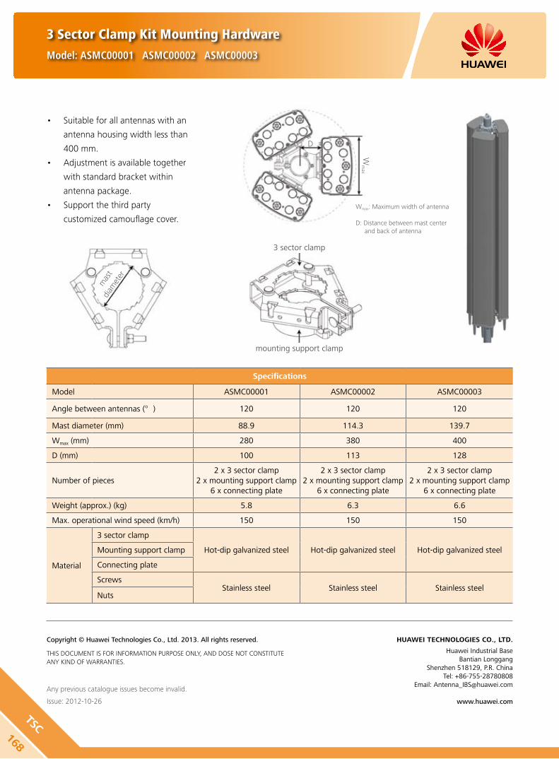
Suitable for all antennas with an •
antenna housing width less than
400 mm.
Adjustment is available together •
with standard bracket within
antenna package.
Support the third party •
customized camouflage cover.
168
TSC
3 Sector Clamp Kit Mounting Hardware
Model: ASMC00001 ASMC00002 ASMC00003
Any previous catalogue issues become invalid.
Issue: 2012-10-26
HUAWEI TECHNOLOGIES CO., LTD.
Huawei Industrial BaseBantian Longgang
Shenzhen 518129, P.R. ChinaTel: +86-755-28780808
Email: [email protected]
www.huawei.com
Copyright © Huawei Technologies Co., Ltd. 2013. All rights reserved.
THIS DOCUMENT IS FOR INFORMATION PURPOSE ONLY, AND DOSE NOT CONSTITUTE ANY KIND OF WARRANTIES.
Specifications
Model ASMC00001 ASMC00002 ASMC00003
Angle between antennas (°) 120 120 120
Mast diameter (mm) 88.9 114.3 139.7
Wmax (mm) 280 380 400
D (mm) 100 113 128
Number of pieces2 x 3 sector clamp
2 x mounting support clamp6 x connecting plate
2 x 3 sector clamp2 x mounting support clamp
6 x connecting plate
2 x 3 sector clamp 2 x mounting support clamp
6 x connecting plate
Weight (approx.) (kg) 5.8 6.3 6.6
Max. operational wind speed (km/h) 150 150 150
Material
3 sector clamp
Hot-dip galvanized steel Hot-dip galvanized steel Hot-dip galvanized steelMounting support clamp
Connecting plate
ScrewsStainless steel Stainless steel Stainless steel
Nuts
mas
t di
amet
er
Wm
ax
D
3 sector clamp
mounting support clamp
Wmax: Maximum width of antenna
D: Distance between mast center and back of antenna

169AIS
G Col
or C
odin
g
Stan
dard
AISG Color Coding Standard
AISG Color Coding for Connectors on Base Station Antennas
Upper Band Edge Range Assigned Color Code Base Color Tag
700MHz to 1000MHz RAL 3020 r
1001MHz to 1700MHz RAL 6029 g
1701MHz to 2300MHz RAL 5015 b
2301MHz to 4000MHz RAL 1023 y
One Color making Different Pattern on Dual-band or Multi-band
r,g,b,y
Dual-band Antenna
Tri-band Antenna
Quad-band Antenna
Penta-band Antenna
800/900MHz EasyRET
1800Mhz/2/2.6GHz EasyRET
800/2100MHz EasyRET
1800MHz/2/2.6GHz MET
800/1800MHz/2/2.6GHz EasyRET
800/900/1800MHz/2/2.6GHz EasyRET

170
AISG Color Coding
Standard
AISG Color Coding Standard
Huawei RCU SN Rule
Any previous catalogue issues become invalid.
Issue: 2012-10-26
HUAWEI TECHNOLOGIES CO., LTD.
Huawei Industrial BaseBantian Longgang
Shenzhen 518129, P.R. ChinaTel: +86-755-28780808
Email: [email protected]
www.huawei.com
Copyright © Huawei Technologies Co., Ltd. 2013. All rights reserved.
THIS DOCUMENT IS FOR INFORMATION PURPOSE ONLY, AND DOSE NOT CONSTITUTE ANY KIND OF WARRANTIES.
Total: 19bytes
Factory code
Total 10 alphanumeric, com from
relative antenna
3~7, last 4 digits of antenna BBOM
8th type: Year(last no. of year)
9th type: Month (1~9, A,B ,C)
10~13th type: running no.
ALD Category: 1 Capital letter
D~G: TMA, may have more option in the future.
P: External pre-commission RCU, may have more option
in the future.
M: integrated RCU, may have more option in the future
B: Normal RCU, ARCU2004, ARCU1115
Color coding according AISG standard
Small letter: array color and pattern
r-red, rr-2nd red, rrr-3rd red, etc
g-green, gg-2nd green, etc
b-blue, bb-2nd blue, etc.
y-yellow, yy-2nd yellow, etc.
Capital letter: array position indicator (if needed)
Horizontal-L,CL,C,CR,R
Vertical-T,MT,M,MB,B
Note: array color and pattern defined by HW, array
position HW use definition in AISG standard
Make up 0~9 digits,
decided by relevant
latter color coding ,
fill 19digits
H W M X X X X X r RRX

Antenna Line ProductsB

The dual tower mounted amplifier (DTMA) is a low-noise amplifier installed near the antenna. It helps to improve the
signal-to-noise ratio and enhance the receiving sensibility of the BTS system. It enhances the uplink coverage and improves
uplink and downlink imbalance of the base station. It effectively reduces the transmitting power of cellphones, improves
voice and data communication quality.
Product Description
High linearity and low noise performance. y
Balanced LNA design and power failure bypass for high reliability. y
Light weight and compact design. y
Variable gain: 8 - 16 dB, default gain: 12 dB. y
Wall mounting and mast mounting. y
Built-in lightning protection up to 10 kA. y
Support AISG 1.1 and AISG 2.0 protocol. y
Features
Appearance and Block Diagram
DTMA08-008 Model: ATA801100 (AISG 1.1)
DTMA08-009 Model: ATA802000 (AISG 2.0)
172
RX : 832 - 862MHz
TX : 791 - 821MHz

DTMA08-008 Model: ATA801100 (AISG 1.1)
DTMA08-009 Model: ATA802000 (AISG 2.0)
Tx Specifications
Frequency range (MHz) 791 - 821
Bandwidth (MHz) 30
Insertion loss* (dB) Avg. < 0.4
Return loss (dB) ≥ 18
Input power (W) < 160 (+52 dBm) CW
< 2000 (+63 dBm) peak
Intermodulation products in Rx band (dBm) ≤ -117 (2 TX carriers at +43 dBm)
Rx Specifications
Frequency range (MHz) 832 - 862
Bandwidth (MHz) 30
Return loss(dB) ≥ 18 (DC ON) ≥ 13 (DC OFF)
Insertion loss in by-pass mode (dB) ≤ 3 (DC OFF)
Gain (dB) 8 - 16 (0.5 dB Step, Default gain: 12 dB)
Noise figure** (dB) Avg. < 1.4 (12 dB Gain, +22 ... +28 )
Output 1dB compression (dBm) ≥ 8 (12 dB Gain)
OIP3 (dBm) ≥ 20 (12 dB Gain)
Electrical properties
CWA Mode AISG Mode
DC supply voltage (V) 8.5 - 15 9 - 30
Operating current per TMA (mA) (without RET)
40 - 110 40 - 370
Alarm management (mA) 150 - 280 AISG
Power consumption (W) < 3.5
Environmental Specification
Operating temperature range () -40 .. +65
IP rating IP67
MTBF (hours) > 1,000,000
EMC ETS 300 342-3
Lightning protection (kA) 10 (8/20 us)
Mechanical Specification
DTMA dimensions (W x H x D) (mm) 190 x 240 x 120 (without connectors, without brackets)
Packing dimensions (W x H x D) (mm) 365 x 515 x 215
DTMA weight (kg) ≤ 6.1 (with brackets)
Packing weight (kg) ≤ 7.4
DTMA Volume (L) Approx. 5.5
AISG connector8-pin female, IEC 60130-9 (pin1 & pin6: 8.5V - 30V DC, pin3: RS485B, pin5:
RS485A, pin7: DC return, other pins: not connected)
MountingWall mounting: with 4 screws (max. 8 mm diameter)
Mast mounting
Mast diameter (mm) Default: 30 - 125 // Optional: 40 - 140
Connector 4 x 7/16 DIN Female (Long neck)
173RX
: 83
2 - 8
62M
Hz
TX : 79
1 - 8
21M
Hz

DTMA08-008 Model: ATA801100 (AISG 1.1)
DTMA08-009 Model: ATA802000 (AISG 2.0)
Unit: mm
Any previous catalogue issues become invalid.
Issue: 2012-10-26
HUAWEI TECHNOLOGIES CO., LTD.
Huawei Industrial BaseBantian Longgang
Shenzhen 518129, P.R. ChinaTel: +86-755-28780808
Email: [email protected]
www.huawei.com
Copyright © Huawei Technologies Co., Ltd. 2013. All rights reserved.
THIS DOCUMENT IS FOR INFORMATION PURPOSE ONLY, AND DOSE NOT CONSTITUTE ANY KIND OF WARRANTIES.
174
RX : 832 - 862MHz
TX : 791 - 821MHz

The dual tower mounted amplifier (DTMA) is a low-noise amplifier installed near the antenna. It helps to improve the
signal-to-noise ratio and enhance the receiving sensibility of the BTS. It enhances the uplink coverage and improves uplink
and downlink imbalance of the BTS. It effectively reduces the transmitting power of cellphones, improves voice and data
communication quality.
DTMA09-014 Model: ATA901102 (AISG 1.1)
DTMA09-015 Model: ATA902002 (AISG 2.0)
Product Description
High linearity and low noise performance. y
Balanced LNA design and power failure bypass for high reliability. y
Light weight and compact design. y
Variable gain: 8 - 16 dB, default gain: 12 dB. y
Wall mounting and mast mounting. y
Built-in lightning protection up to 10 kA. y
Support AISG 1.1 and AISG 2.0 protocol. y
Features
Appearance and Block Diagram
175RX
: 88
0 - 9
05M
Hz
TX : 92
5 - 9
50M
Hz

DTMA09-014 Model: ATA901102 (AISG 1.1)
DTMA09-015 Model: ATA902002 (AISG 2.0)
Tx Specifications
Frequency range (MHz) 925 - 950
Bandwidth (MHz) 25
Insertion loss* (dB) Avg. < 0.4
Return loss (dB) ≥ 18
Input power (W) < 160 (+52 dBm) CW
< 2000 (+63 dBm) peak
Intermodulation products in Rx band (dBm) ≤ -117 (2 TX carriers at +43 dBm)
Rx Specifications
Frequency range (MHz) 880 - 905
Bandwidth (MHz) 25
Return loss(dB) ≥ 18 (DC ON)≥ 13 (DC OFF)
Insertion loss in by-pass mode (dB) ≤ 3.0 (DC OFF)
Gain (dB) 8 - 16 (0.5 dB Step, Default gain: 12 dB)
Noise figure** (dB) Avg. < 1.4 (12 dB Gain, +22 ... +28 )
Output 1dB compression (dBm) ≥ 8 (12 dB Gain)
OIP3 (dBm) ≥ 20 (12 dB Gain)
Electrical properties
CWA Mode AISG Mode
DC supply voltage (V) 8.5 - 15 9 - 30
Operating current per TMA (mA) (without RET)
40 - 110 40 - 370
Alarm management (mA) 150 - 280 AISG
Power consumption (W) < 3.5
Environmental Specification
Operating temperature range () -40 .. +65
IP rating IP67
MTBF (hours) > 1,000,000
EMC ETS 300 342-3
Lightning protection (kA) 10 (8/20 us)
Mechanical Specification
DTMA dimensions (W x H x D) (mm) 198 x 308 x 70.5 (without connectors, without brackets)
Packing dimensions (W x H x D) (mm) 315 x 515 x 190
DTMA weight (kg) ≤ 5.5 (with brackets)
Packing weight (kg) ≤ 6.6
DTMA Volume (L) Approx. 4.3
AISG connector8-pin female, IEC 60130-9 (pin1 & pin6: 8.5V - 30V DC, pin3: RS485B, pin5:
RS485A, pin7: DC return, other pins: not connected)
MountingWall mounting: with 4 screws (max. 8 mm diameter)
Mast mounting
Mast diameter (mm) Default: 30 - 125 // Optional: 40 - 140
Connector 4 x 7/16 DIN Female (Long neck)
176
RX : 880 - 905MHz
TX : 925 - 950MHz

DTMA09-014 Model: ATA901102 (AISG 1.1)
DTMA09-015 Model: ATA902002 (AISG 2.0)
Any previous catalogue issues become invalid.
Issue: 2012-10-26
HUAWEI TECHNOLOGIES CO., LTD.
Huawei Industrial BaseBantian Longgang
Shenzhen 518129, P.R. ChinaTel: +86-755-28780808
Email: [email protected]
www.huawei.com
Copyright © Huawei Technologies Co., Ltd. 2013. All rights reserved.
THIS DOCUMENT IS FOR INFORMATION PURPOSE ONLY, AND DOSE NOT CONSTITUTE ANY KIND OF WARRANTIES.
Unit: mm
177RX
: 88
0 - 9
05M
Hz
TX : 92
5 - 9
50M
Hz
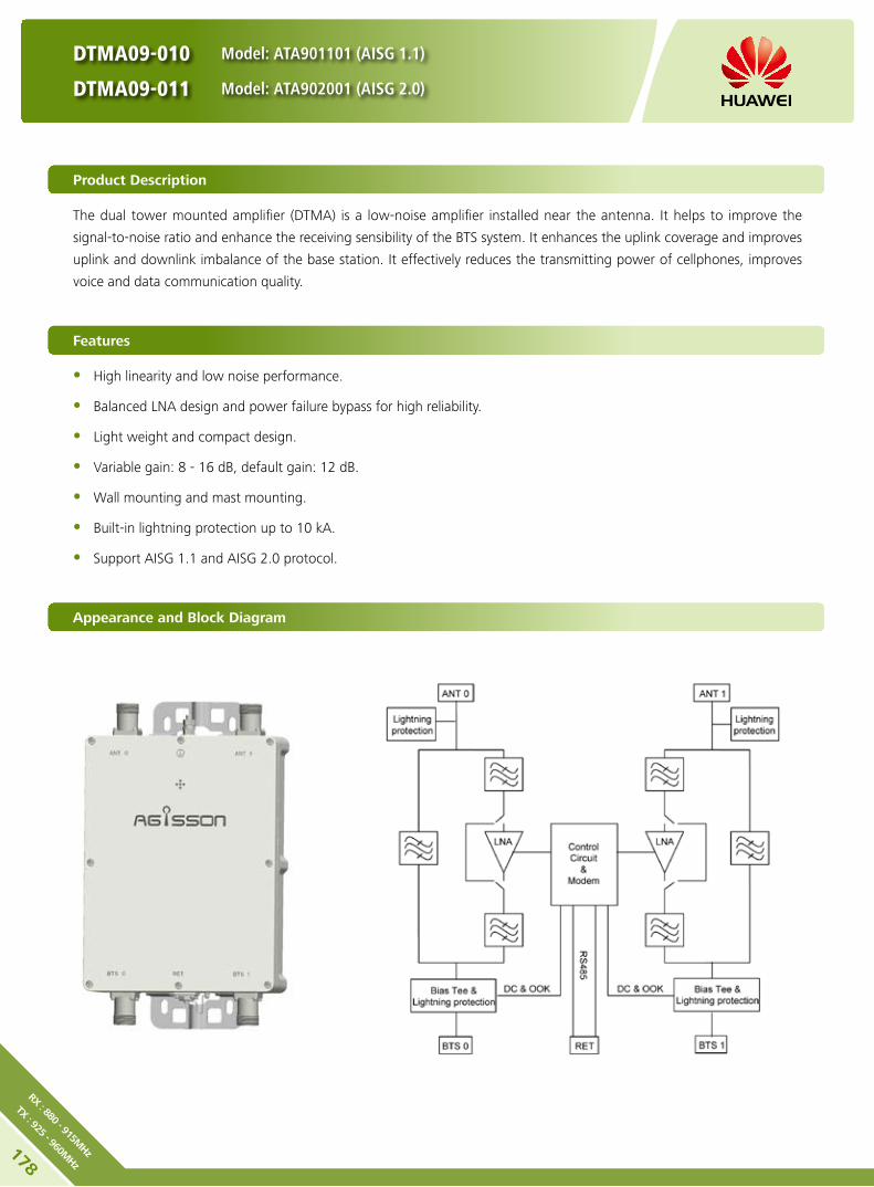
The dual tower mounted amplifier (DTMA) is a low-noise amplifier installed near the antenna. It helps to improve the
signal-to-noise ratio and enhance the receiving sensibility of the BTS system. It enhances the uplink coverage and improves
uplink and downlink imbalance of the base station. It effectively reduces the transmitting power of cellphones, improves
voice and data communication quality.
DTMA09-010 Model: ATA901101 (AISG 1.1)
DTMA09-011 Model: ATA902001 (AISG 2.0)
Product Description
High linearity and low noise performance. y
Balanced LNA design and power failure bypass for high reliability. y
Light weight and compact design. y
Variable gain: 8 - 16 dB, default gain: 12 dB. y
Wall mounting and mast mounting. y
Built-in lightning protection up to 10 kA. y
Support AISG 1.1 and AISG 2.0 protocol. y
Features
Appearance and Block Diagram
178
RX : 880 - 915MHz
TX : 925 - 960MHz

DTMA09-010 Model: ATA901101 (AISG 1.1)
DTMA09-011 Model: ATA902001 (AISG 2.0)
Tx Specifications
Frequency range (MHz) 925 - 960
Bandwidth (MHz) 35
Insertion loss* (dB) Avg. < 0.4
Return loss (dB) ≥ 18
Input power (W) < 160 (+52 dBm) CW
< 2000 (+63 dBm) peak
Intermodulation products in Rx band (dBm) ≤ -117 (2 TX carriers at +43 dBm)
Rx Specifications
Frequency range (MHz) 880 - 915
Bandwidth (MHz) 35
Return loss(dB) ≥ 18 (DC ON)≥ 13 (DC OFF)
Insertion loss in by-pass mode (dB) ≤ 3.0 (DC OFF)
Gain (dB) 8 - 16 (0.5 dB Step, Default gain: 12 dB)
Noise figure** (dB) Avg. < 1.4 (12 dB Gain, +22 ... +28 )
Output 1dB compression (dBm) ≥ 8 (12 dB Gain)
OIP3 (dBm) ≥ 20 (12 dB Gain)
Electrical properties
CWA Mode AISG Mode
DC supply voltage (V) 8.5 - 15 9 - 30
Operating current per TMA (mA) (without RET)
40 - 110 40 - 370
Alarm management (mA) 150 - 280 AISG
Power consumption (W) < 3.5
Environmental Specification
Operating temperature range () -40 .. +65
IP rating IP67
MTBF (hours) > 1,000,000
EMC ETS 300 342-3
Lightning protection (kA) 10 (8/20 us)
Mechanical Specification
DTMA dimensions (W x H x D) (mm) 248 x 324 x 75.5 (without connectors, without brackets)
Packing dimensions (W x H x D) (mm) 365 x 515 x 215
DTMA weight (kg) ≤ 6.5 (with brackets)
Packing weight (kg) ≤ 7.7
DTMA Volume (L) Approx. 6.1
AISG connector8-pin female, IEC 60130-9 (pin1 & pin6: 8.5V - 30V DC, pin3: RS485B, pin5:
RS485A, pin7: DC return, other pins: not connected)
MountingWall mounting: with 4 screws (max. 8 mm diameter)
Mast mounting
Mast diameter (mm) Default: 30 - 125 // Optional: 40 - 140
Connector 4 x 7/16 DIN Female (Long neck)
179RX
: 88
0 - 9
15M
Hz
TX : 92
5 - 9
60M
Hz

DTMA09-010 Model: ATA901101 (AISG 1.1)
DTMA09-011 Model: ATA902001 (AISG 2.0)
Any previous catalogue issues become invalid.
Issue: 2012-10-26
HUAWEI TECHNOLOGIES CO., LTD.
Huawei Industrial BaseBantian Longgang
Shenzhen 518129, P.R. ChinaTel: +86-755-28780808
Email: [email protected]
www.huawei.com
Copyright © Huawei Technologies Co., Ltd. 2013. All rights reserved.
THIS DOCUMENT IS FOR INFORMATION PURPOSE ONLY, AND DOSE NOT CONSTITUTE ANY KIND OF WARRANTIES.
Unit: mm
180
RX : 880 - 915MHz
TX : 925 - 960MHz

The dual tower mounted amplifier (DTMA) is a low-noise amplifier installed near the antenna. It helps to improve the
signal-to-noise ratio and enhance the receiving sensibility of the BTS system. It enhances the uplink coverage and improves
uplink and downlink imbalance of the base station. It effectively reduces the transmitting power of cellphones, improves
voice and data communication quality.
DTMA09-016 Model: ATA901103 (AISG 1.1)
DTMA09-017 Model: ATA902003 (AISG 2.0)
Product Description
High linearity and low noise performance. y
Balanced LNA design and power failure bypass for high reliability. y
Light weight and compact design. y
Variable gain: 8 - 16 dB, default gain: 12 dB. y
Wall mounting and mast mounting. y
Built-in lightning protection up to 10 kA. y
Support AISG 1.1 and AISG 2.0 protocol. y
Features
Appearance and Block Diagram
181RX
: 89
0 - 9
15 M
Hz
TX : 93
5 - 9
60 M
Hz
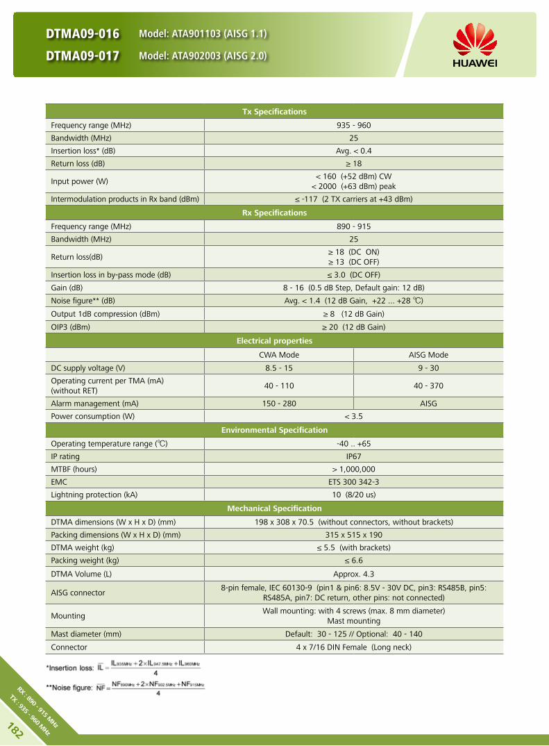
DTMA09-016 Model: ATA901103 (AISG 1.1)
DTMA09-017 Model: ATA902003 (AISG 2.0)
Tx Specifications
Frequency range (MHz) 935 - 960
Bandwidth (MHz) 25
Insertion loss* (dB) Avg. < 0.4
Return loss (dB) ≥ 18
Input power (W) < 160 (+52 dBm) CW
< 2000 (+63 dBm) peak
Intermodulation products in Rx band (dBm) ≤ -117 (2 TX carriers at +43 dBm)
Rx Specifications
Frequency range (MHz) 890 - 915
Bandwidth (MHz) 25
Return loss(dB) ≥ 18 (DC ON)≥ 13 (DC OFF)
Insertion loss in by-pass mode (dB) ≤ 3.0 (DC OFF)
Gain (dB) 8 - 16 (0.5 dB Step, Default gain: 12 dB)
Noise figure** (dB) Avg. < 1.4 (12 dB Gain, +22 ... +28 )
Output 1dB compression (dBm) ≥ 8 (12 dB Gain)
OIP3 (dBm) ≥ 20 (12 dB Gain)
Electrical properties
CWA Mode AISG Mode
DC supply voltage (V) 8.5 - 15 9 - 30
Operating current per TMA (mA) (without RET)
40 - 110 40 - 370
Alarm management (mA) 150 - 280 AISG
Power consumption (W) < 3.5
Environmental Specification
Operating temperature range () -40 .. +65
IP rating IP67
MTBF (hours) > 1,000,000
EMC ETS 300 342-3
Lightning protection (kA) 10 (8/20 us)
Mechanical Specification
DTMA dimensions (W x H x D) (mm) 198 x 308 x 70.5 (without connectors, without brackets)
Packing dimensions (W x H x D) (mm) 315 x 515 x 190
DTMA weight (kg) ≤ 5.5 (with brackets)
Packing weight (kg) ≤ 6.6
DTMA Volume (L) Approx. 4.3
AISG connector8-pin female, IEC 60130-9 (pin1 & pin6: 8.5V - 30V DC, pin3: RS485B, pin5:
RS485A, pin7: DC return, other pins: not connected)
MountingWall mounting: with 4 screws (max. 8 mm diameter)
Mast mounting
Mast diameter (mm) Default: 30 - 125 // Optional: 40 - 140
Connector 4 x 7/16 DIN Female (Long neck)
182
RX : 890 - 915 MHz
TX : 935 - 960 MHz

DTMA09-016 Model: ATA901103 (AISG 1.1)
DTMA09-017 Model: ATA902003 (AISG 2.0)
Any previous catalogue issues become invalid.
Issue: 2012-10-26
HUAWEI TECHNOLOGIES CO., LTD.
Huawei Industrial BaseBantian Longgang
Shenzhen 518129, P.R. ChinaTel: +86-755-28780808
Email: [email protected]
www.huawei.com
Copyright © Huawei Technologies Co., Ltd. 2013. All rights reserved.
THIS DOCUMENT IS FOR INFORMATION PURPOSE ONLY, AND DOSE NOT CONSTITUTE ANY KIND OF WARRANTIES.
Unit: mm
183RX
: 89
0 - 9
15 M
Hz
TX : 93
5 - 9
60 M
Hz

The dual tower mounted amplifier (DTMA) is a low-noise amplifier installed near the antenna. It helps to improve the
signal-to-noise ratio and enhance the receiving sensibility of the BTS system. It enhances the uplink coverage and improves
uplink and downlink imbalance of the base station. It effectively reduces the transmitting power of cellphones, improves
voice and data communication quality.
DTMA18-022 Model: ATA181101 (AISG 1.1)
DTMA18-023 Model: ATA182001 (AISG 2.0)
Product Description
High linearity and low noise performance. y
Power failure bypass for high reliability. y
Light weight and compact design. y
Wall mounting and mast mounting. y
Built-in lightning protection up to 10 kA. y
Support AISG 1.1 and AISG 2.0 protocol. y
Features
Appearance and Block Diagram
184
RX : 1710 - 1785 MHz
TX : 1805 - 1880 MHz
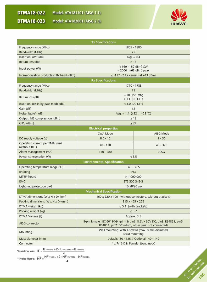
DTMA18-022 Model: ATA181101 (AISG 1.1)
DTMA18-023 Model: ATA182001 (AISG 2.0)
Tx Specifications
Frequency range (MHz) 1805 - 1880
Bandwidth (MHz) 75
Insertion loss* (dB) Avg. < 0.4
Return loss (dB) ≥ 18
Input power (W) < 160 (+52 dBm) CW
< 2000 (+63 dBm) peak
Intermodulation products in Rx band (dBm) ≤ -117 (2 TX carriers at +43 dBm)
Rx Specifications
Frequency range (MHz) 1710 - 1785
Bandwidth (MHz) 75
Return loss(dB) ≥ 18 (DC ON)≥ 13 (DC OFF)
Insertion loss in by-pass mode (dB) ≤ 3.0 (DC OFF)
Gain (dB) 12
Noise figure** (dB) Avg. < 1.4 (+22 ... +28 )
Output 1dB compression (dBm) ≥ 12
OIP3 (dBm) ≥ 24
Electrical properties
CWA Mode AISG Mode
DC supply voltage (V) 8.5 - 15 9 - 30
Operating current per TMA (mA) (without RET)
40 - 120 40 - 370
Alarm management (mA) 150 - 280 AISG
Power consumption (W) < 3.5
Environmental Specification
Operating temperature range () -40 .. +65
IP rating IP67
MTBF (hours) > 1,000,000
EMC ETS 300 342-3
Lightning protection (kA) 10 (8/20 us)
Mechanical Specification
DTMA dimensions (W x H x D) (mm) 160 x 220 x 100 (without connectors, without brackets)
Packing dimensions (W x H x D) (mm) 315 x 465 x 225
DTMA weight (kg) ≤ 5.1 (with brackets)
Packing weight (kg) ≤ 6.2
DTMA Volume (L) Approx. 3.5
AISG connector8-pin female, IEC 60130-9 (pin1 & pin6: 8.5V - 30V DC, pin3: RS485B, pin5:
RS485A, pin7: DC return, other pins: not connected)
MountingWall mounting: with 4 screws (max. 8 mm diameter)
Mast mounting
Mast diameter (mm) Default: 30 - 125 // Optional: 40 - 140
Connector 4 x 7/16 DIN Female (Long neck)
185RX
: 17
10 - 17
85 M
Hz
TX : 18
05 - 18
80 M
Hz

DTMA18-022 Model: ATA181101 (AISG 1.1)
DTMA18-023 Model: ATA182001 (AISG 2.0)
Any previous catalogue issues become invalid.
Issue: 2012-10-26
HUAWEI TECHNOLOGIES CO., LTD.
Huawei Industrial BaseBantian Longgang
Shenzhen 518129, P.R. ChinaTel: +86-755-28780808
Email: [email protected]
www.huawei.com
Copyright © Huawei Technologies Co., Ltd. 2013. All rights reserved.
THIS DOCUMENT IS FOR INFORMATION PURPOSE ONLY, AND DOSE NOT CONSTITUTE ANY KIND OF WARRANTIES.
Unit: mm
186
RX : 1710 - 1785 MHz
TX : 1805 - 1880 MHz

The dual tower mounted amplifier (DTMA) is a low-noise amplifier installed near the antenna. It helps to improve the
signal-to-noise ratio and enhance the receiving sensibility of the BTS system. It enhances the uplink coverage and improves
uplink and downlink imbalance of the base station. It effectively reduces the transmitting power of cellphones, improves
voice and data communication quality.
DTMA21-006 Model: ATA211101 (AISG 1.1)
DTMA21-007 Model: ATA212001 (AISG 2.0
Product Description
High linearity and low noise performance. y
Power failure bypass for high reliability. y
Light weight and compact design. y
Wall mounting and mast mounting. y
Built-in lightning protection up to 10 kA. y
Support AISG 1.1 and AISG 2.0 protocol. y
Features
Appearance and Block Diagram
187RX
: 19
20 - 19
80M
Hz
TX : 21
10 - 21
70M
Hz

DTMA21-006 Model: ATA211101 (AISG 1.1)
DTMA21-007 Model: ATA212001 (AISG 2.0
Tx Specifications
Frequency range (MHz) 2110 - 2170
Bandwidth (MHz) 60
Insertion loss* (dB) Avg. < 0.25
Return loss (dB) ≥ 18
Input power (W) < 160 (+52 dBm) CW
< 2000 (+63 dBm) peak
Intermodulation products in Rx band (dBm) ≤ -122 (2 TX carriers at +43 dBm)
Rx Specifications
Frequency range (MHz) 1920 - 1980
Bandwidth (MHz) 60
Return loss(dB) ≥ 18 (DC ON)≥ 15 (DC OFF)
Insertion loss in by-pass mode (dB) ≤ 3.0 (DC OFF)
Gain (dB) 12 ±1
Noise figure** (dB) Avg. < 1.2 (+22 ... +28 )
Output 1dB compression (dBm) ≥ 12
OIP3 (dBm) ≥ 24
Electrical properties
CWA Mode AISG Mode
DC supply voltage (V) 8.5 - 15 9 - 30
Operating current per TMA (mA) (without RET)
40 - 120 40 - 370
Alarm management (mA) 150 - 280 AISG
Power consumption (W) < 3.5
Environmental Specification
Operating temperature range () -40 .. +65
IP rating IP67
MTBF (hours) > 1,000,000
EMC ETS 300 342-3
Lightning protection (kA) 10 (8/20 us)
Mechanical Specification
DTMA dimensions (W x H x D) (mm) 160 x 205 x 54.5 (without connectors, without brackets)
Packing dimensions (W x H x D) (mm) 265 x 395 x 195
DTMA weight (kg) ≤ 3.3 (with brackets)
Packing weight (kg) ≤ 4.0
DTMA Volume (L) Approx. 1.8
AISG connector8-pin female, IEC 60130-9 (pin1 & pin6: 8.5V - 30V DC, pin3: RS485B, pin5:
RS485A, pin7: DC return, other pins: not connected)
MountingWall mounting: with 4 screws (max. 8 mm diameter)
Mast mounting
Mast diameter (mm) Default: 30 - 125 // Optional: 40 - 140
Connector 4 x 7/16 DIN Female (Long neck)
188
RX : 1920 - 1980MHz
TX : 2110 - 2170MHz
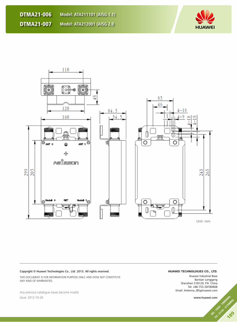
DTMA21-006 Model: ATA211101 (AISG 1.1)
DTMA21-007 Model: ATA212001 (AISG 2.0
Any previous catalogue issues become invalid.
Issue: 2012-10-26
HUAWEI TECHNOLOGIES CO., LTD.
Huawei Industrial BaseBantian Longgang
Shenzhen 518129, P.R. ChinaTel: +86-755-28780808
Email: [email protected]
www.huawei.com
Copyright © Huawei Technologies Co., Ltd. 2013. All rights reserved.
THIS DOCUMENT IS FOR INFORMATION PURPOSE ONLY, AND DOSE NOT CONSTITUTE ANY KIND OF WARRANTIES.
Unit: mm
189RX
: 19
20 - 19
80M
Hz
TX : 21
10 - 21
70M
Hz
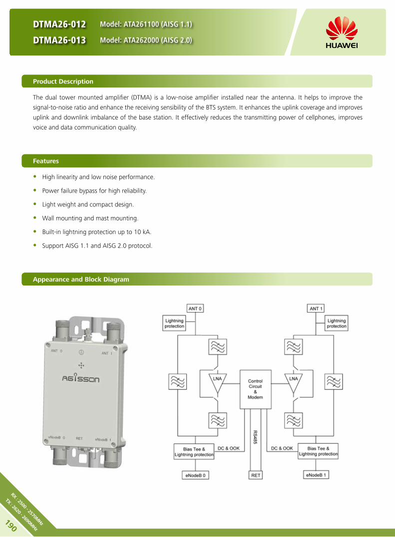
The dual tower mounted amplifier (DTMA) is a low-noise amplifier installed near the antenna. It helps to improve the
signal-to-noise ratio and enhance the receiving sensibility of the BTS system. It enhances the uplink coverage and improves
uplink and downlink imbalance of the base station. It effectively reduces the transmitting power of cellphones, improves
voice and data communication quality.
DTMA26-012 Model: ATA261100 (AISG 1.1)
DTMA26-013 Model: ATA262000 (AISG 2.0)
Product Description
High linearity and low noise performance. y
Power failure bypass for high reliability. y
Light weight and compact design. y
Wall mounting and mast mounting. y
Built-in lightning protection up to 10 kA. y
Support AISG 1.1 and AISG 2.0 protocol. y
Features
Appearance and Block Diagram
190
RX : 2500 - 2570MHz
TX : 2620 - 2690MHz
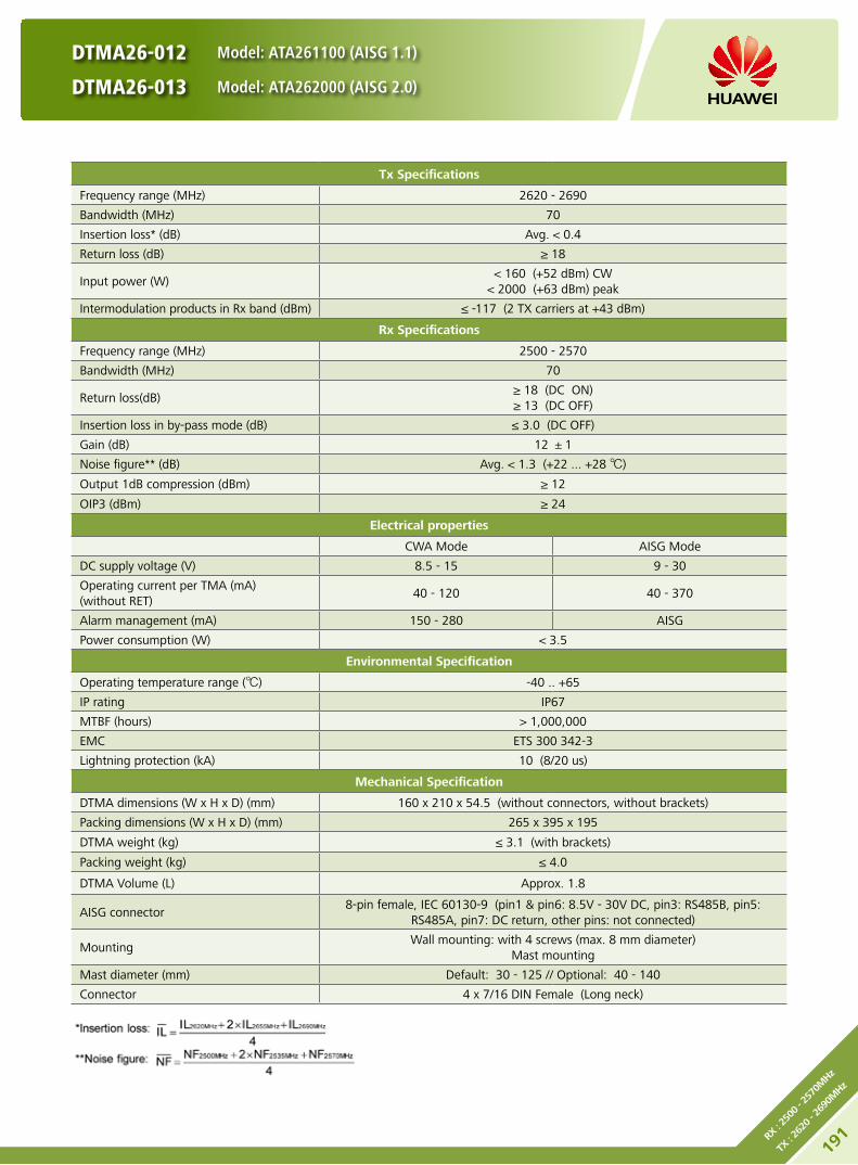
DTMA26-012 Model: ATA261100 (AISG 1.1)
DTMA26-013 Model: ATA262000 (AISG 2.0)
Tx Specifications
Frequency range (MHz) 2620 - 2690
Bandwidth (MHz) 70
Insertion loss* (dB) Avg. < 0.4
Return loss (dB) ≥ 18
Input power (W) < 160 (+52 dBm) CW
< 2000 (+63 dBm) peak
Intermodulation products in Rx band (dBm) ≤ -117 (2 TX carriers at +43 dBm)
Rx Specifications
Frequency range (MHz) 2500 - 2570
Bandwidth (MHz) 70
Return loss(dB) ≥ 18 (DC ON)≥ 13 (DC OFF)
Insertion loss in by-pass mode (dB) ≤ 3.0 (DC OFF)
Gain (dB) 12 ±1
Noise figure** (dB) Avg. < 1.3 (+22 ... +28 )
Output 1dB compression (dBm) ≥ 12
OIP3 (dBm) ≥ 24
Electrical properties
CWA Mode AISG Mode
DC supply voltage (V) 8.5 - 15 9 - 30
Operating current per TMA (mA) (without RET)
40 - 120 40 - 370
Alarm management (mA) 150 - 280 AISG
Power consumption (W) < 3.5
Environmental Specification
Operating temperature range () -40 .. +65
IP rating IP67
MTBF (hours) > 1,000,000
EMC ETS 300 342-3
Lightning protection (kA) 10 (8/20 us)
Mechanical Specification
DTMA dimensions (W x H x D) (mm) 160 x 210 x 54.5 (without connectors, without brackets)
Packing dimensions (W x H x D) (mm) 265 x 395 x 195
DTMA weight (kg) ≤ 3.1 (with brackets)
Packing weight (kg) ≤ 4.0
DTMA Volume (L) Approx. 1.8
AISG connector8-pin female, IEC 60130-9 (pin1 & pin6: 8.5V - 30V DC, pin3: RS485B, pin5:
RS485A, pin7: DC return, other pins: not connected)
MountingWall mounting: with 4 screws (max. 8 mm diameter)
Mast mounting
Mast diameter (mm) Default: 30 - 125 // Optional: 40 - 140
Connector 4 x 7/16 DIN Female (Long neck)
191RX
: 25
00 - 25
70M
Hz
TX : 26
20 - 26
90M
Hz

DTMA26-012 Model: ATA261100 (AISG 1.1)
DTMA26-013 Model: ATA262000 (AISG 2.0)
Any previous catalogue issues become invalid.
Issue: 2012-10-26
HUAWEI TECHNOLOGIES CO., LTD.
Huawei Industrial BaseBantian Longgang
Shenzhen 518129, P.R. ChinaTel: +86-755-28780808
Email: [email protected]
www.huawei.com
Copyright © Huawei Technologies Co., Ltd. 2013. All rights reserved.
THIS DOCUMENT IS FOR INFORMATION PURPOSE ONLY, AND DOSE NOT CONSTITUTE ANY KIND OF WARRANTIES.
Unit: mm
192
RX : 2500 - 2570MHz
TX : 2620 - 2690MHz

The dual tower mounted amplifier (DTMA) is a low-noise amplifier installed near the antenna. It helps to improve the
signal-to-noise ratio and enhance the receiving sensibility of the BTS system. It enhances the uplink coverage and improves
uplink and downlink imbalance of the base station. It effectively reduces the transmitting power of cellphones, improves
voice and data communication quality.
DTMA09-018
Model: ATA902004 (AISG 2.0)
Product Description
High linearity and low noise performance. y
Balanced LNA design and power failure bypass for high reliability. y
Light weight and compact design. y
Variable gain: 8 - 16 dB, default gain: 16 dB. y
Wall mounting and mast mounting. y
Built-in lightning protection up to 10 kA. y
Support AISG 2.0 protocol. y
Features
Appearance and Block Diagram
Preliminary Issue
193RX
: 88
0 - 9
15M
Hz
TX : 92
5 - 9
60M
Hz

Tx Specifications
Frequency range (MHz) 925 - 960
Bandwidth (MHz) 35
Insertion loss* (dB) Avg. < 0.4
Return loss (dB) ≥ 18
Input power (W) < 160 (+52 dBm) CW
< 2000 (+63 dBm) peak
Intermodulation products in Rx band (dBm) ≤ -117 (2 TX carriers at +43 dBm)
Rx Specifications
Frequency range (MHz) 880 - 915
Bandwidth (MHz) 35
Return loss(dB) ≥ 18 (DC ON)≥ 13 (DC OFF)
Insertion loss in by-pass mode (dB) ≤ 3.0 (DC OFF)
Gain (dB) 8 - 16 (0.5 dB Step)
Noise figure** (dB) Avg. < 1.3 (16 dB Gain, +22 ... +28 )
Output 1dB compression (dBm) ≥ 12 (16 dB Gain)
OIP3 (dBm) ≥ 24 (16 dB Gain)
Filter Specifications
Frequency range (MHz) 1700 - 2700
Insertion loss (dB) < 0.5
Return loss (dB) ≥ 18
Input power (W) < 160 (+52 dBm) CW
Intermodulation products (dBm) ≤ -117 (3rd order, 2 TX carriers at +43 dBm)
Electrical properties
CWA Mode AISG Mode
DC supply voltage (V) 8.5 - 15 8.5 - 30
Operating current per TMA (mA) (without RET)
40 - 110 (12 V DC) 40 - 370 (12 V DC)
Alarm management (mA) 150 - 280 (12 V DC) AISG
Power consumption (W) < 3.5
Environmental Specification
Operating temperature range () -40 .. +65
IP rating IP67
MTBF (hours) > 1,000,000
EMC ETS 300 342-3
Lightning protection (kA) 10 (8/20 us)
Mechanical Specification
RF connectors 4 x 7/16 DIN Female (Long neck)
AISG connector8-pin female, IEC 60130-9 (pin1 & pin6: 8.5V - 30V DC, pin3: RS485B,
pin5: RS485A, pin7: DC return, other pins: not connected)
Mounting Wall mounting // Mast mounting
Weight (kg) ≤ 8.5 (with brackets)
Mast diameter (mm) Default: 30 - 125 // Optional: 40 - 140
Dimensions (W x H x D) (mm) 248 x 324 x 100 (without connectors, without brackets)
Volume (L) Approx. 8.0
DTMA09-018
Model: ATA902004 (AISG 2.0)
Preliminary Issue
194
RX : 880 - 915MHz
TX : 925 - 960MHz

Any previous catalogue issues become invalid.
Issue: 2013-01-08
HUAWEI TECHNOLOGIES CO., LTD.
Huawei Industrial BaseBantian Longgang
Shenzhen 518129, P.R. ChinaTel: +86-755-28780808
Email: [email protected]
www.huawei.com
Copyright © Huawei Technologies Co., Ltd. 2013. All rights reserved.
THIS DOCUMENT IS FOR INFORMATION PURPOSE ONLY, AND DOSE NOT CONSTITUTE ANY KIND OF WARRANTIES.
Unit: mm
DTMA09-018
Model: ATA902004 (AISG 2.0)
Preliminary Issue
195RX
: 88
0 - 9
15M
Hz
TX : 92
5 - 9
60M
Hz

The dual tower mounted amplifier (DTMA) is a low-noise amplifier installed near the antenna. It helps to improve the
signal-to-noise ratio and enhance the receiving sensibility of the BTS system. It enhances the uplink coverage and improves
uplink and downlink imbalance of the base station. It effectively reduces the transmitting power of cellphones, improves
voice and data communication quality.
Product Description
High linearity and low noise performance. y
Power failure bypass for high reliability. y
Light weight and compact design. y
Wall mounting and mast mounting. y
Built-in lightning protection up to 10 kA. y
Support AISG 2.0 protocol. y
Features
Appearance and Block Diagram
DTMA21-019
Model: ATA212004 (AISG 2.0)
Preliminary Issue
196
RX : 1920 - 1980MHz
TX : 2110 - 2170MHz
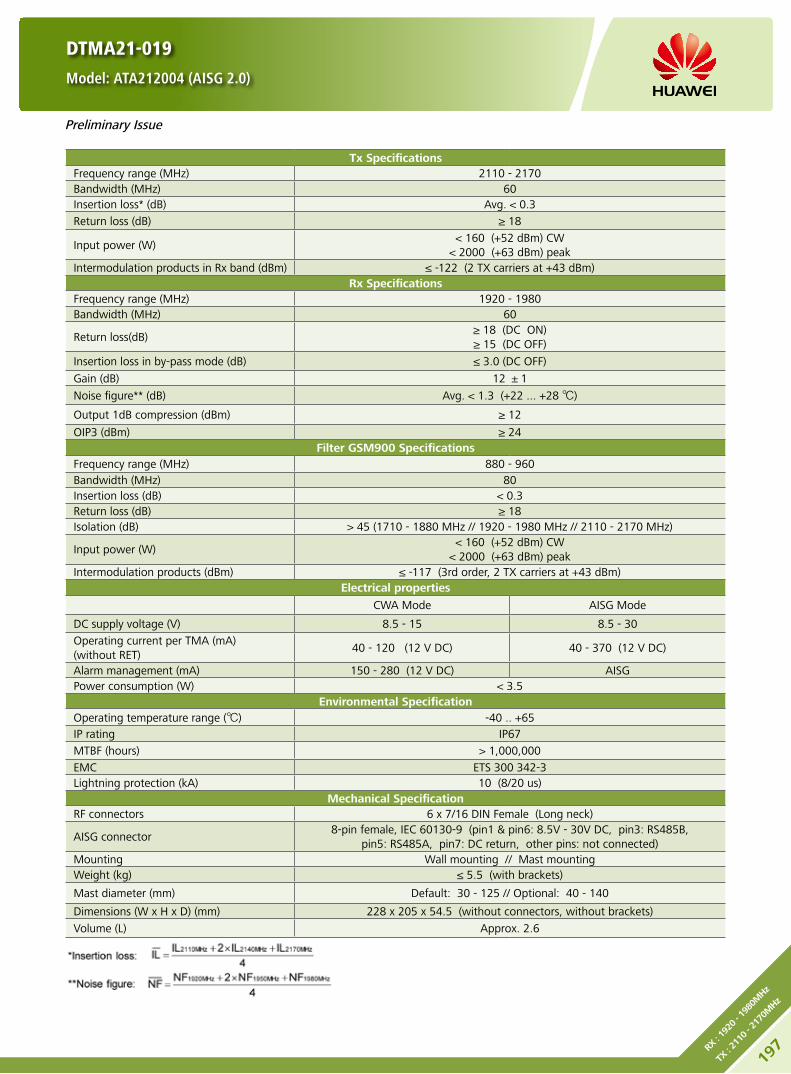
DTMA21-019
Model: ATA212004 (AISG 2.0)
Tx Specifications Frequency range (MHz) 2110 - 2170Bandwidth (MHz) 60Insertion loss* (dB) Avg. < 0.3
Return loss (dB) ≥ 18
Input power (W) < 160 (+52 dBm) CW
< 2000 (+63 dBm) peakIntermodulation products in Rx band (dBm) ≤ -122 (2 TX carriers at +43 dBm)
Rx Specifications Frequency range (MHz) 1920 - 1980Bandwidth (MHz) 60
Return loss(dB) ≥ 18 (DC ON)≥ 15 (DC OFF)
Insertion loss in by-pass mode (dB) ≤ 3.0 (DC OFF)
Gain (dB) 12 ±1
Noise figure** (dB) Avg. < 1.3 (+22 ... +28 )
Output 1dB compression (dBm) ≥ 12
OIP3 (dBm) ≥ 24Filter GSM900 Specifications
Frequency range (MHz) 880 - 960Bandwidth (MHz) 80Insertion loss (dB) < 0.3Return loss (dB) ≥ 18Isolation (dB) > 45 (1710 - 1880 MHz // 1920 - 1980 MHz // 2110 - 2170 MHz)
Input power (W)< 160 (+52 dBm) CW
< 2000 (+63 dBm) peakIntermodulation products (dBm) ≤ -117 (3rd order, 2 TX carriers at +43 dBm)
Electrical properties
CWA Mode AISG Mode
DC supply voltage (V) 8.5 - 15 8.5 - 30
Operating current per TMA (mA) (without RET)
40 - 120 (12 V DC) 40 - 370 (12 V DC)
Alarm management (mA) 150 - 280 (12 V DC) AISGPower consumption (W) < 3.5
Environmental SpecificationOperating temperature range () -40 .. +65IP rating IP67
MTBF (hours) > 1,000,000
EMC ETS 300 342-3Lightning protection (kA) 10 (8/20 us)
Mechanical Specification RF connectors 6 x 7/16 DIN Female (Long neck)
AISG connector8-pin female, IEC 60130-9 (pin1 & pin6: 8.5V - 30V DC, pin3: RS485B,
pin5: RS485A, pin7: DC return, other pins: not connected)Mounting Wall mounting // Mast mountingWeight (kg) ≤ 5.5 (with brackets)
Mast diameter (mm) Default: 30 - 125 // Optional: 40 - 140
Dimensions (W x H x D) (mm) 228 x 205 x 54.5 (without connectors, without brackets)
Volume (L) Approx. 2.6
Preliminary Issue
197RX
: 19
20 - 19
80M
Hz
TX : 21
10 - 21
70M
Hz

Any previous catalogue issues become invalid.
Issue: 2013-01-08
HUAWEI TECHNOLOGIES CO., LTD.
Huawei Industrial BaseBantian Longgang
Shenzhen 518129, P.R. ChinaTel: +86-755-28780808
Email: [email protected]
www.huawei.com
Copyright © Huawei Technologies Co., Ltd. 2013. All rights reserved.
THIS DOCUMENT IS FOR INFORMATION PURPOSE ONLY, AND DOSE NOT CONSTITUTE ANY KIND OF WARRANTIES.
Unit: mm
DTMA21-019
Model: ATA212004 (AISG 2.0)
Preliminary Issue
198
RX : 1920 - 1980MHz
TX : 2110 - 2170MHz

The dual tower mounted amplifier (DTMA) is a low-noise amplifier installed near the antenna. It helps to improve the
signal-to-noise ratio and enhance the receiving sensibility of the BTS system. It enhances the uplink coverage and improves
uplink and downlink imbalance of the base station. It effectively reduces the transmitting power of cellphones, improves
voice and data communication quality.
DTMA21-020
Model: ATA212002 (AISG 2.0)
Product Description
High linearity and low noise performance. y
Power failure bypass for high reliability. y
Light weight and compact design. y
Wall mounting and mast mounting. y
Built-in lightning protection up to 10 kA. y
Support AISG 2.0 protocol. y
Features
Appearance and Block Diagram
Preliminary Issue
199RX
: 19
20 - 19
80M
Hz
TX : 21
10 - 21
70M
Hz

DTMA21-020
Model: ATA212002 (AISG 2.0)
Tx Specifications Frequency range (MHz) 2110 - 2170Bandwidth (MHz) 60Insertion loss* (dB) Avg. < 0.3
Return loss (dB) ≥ 18
Input power (W) < 160 (+52 dBm) CW
< 2000 (+63 dBm) peakIntermodulation products in Rx band (dBm) ≤ -122 (2 TX carriers at +43 dBm)
Rx Specifications Frequency range (MHz) 1920 - 1980Bandwidth (MHz) 60
Return loss(dB) ≥ 18 (DC ON)≥ 15 (DC OFF)
Insertion loss in by-pass mode (dB) ≤ 3.0 (DC OFF)
Gain (dB) 12 ±1
Noise figure** (dB) Avg. < 1.4 (+22 ... +28 )
Output 1dB compression (dBm) ≥ 12
OIP3 (dBm) ≥ 24Filter DCS1800 Specifications
Frequency range (MHz) 1710 - 1880Bandwidth (MHz) 170Insertion loss (dB) ≤ 0.4Return loss (dB) ≥ 18
Input power (W)< 160 (+52 dBm) CW
< 2000 (+63 dBm) peakIntermodulation products (dBm) ≤ -117 (3rd order, 2 TX carriers at +43 dBm)
Electrical properties
CWA Mode AISG Mode
DC supply voltage (V) 8.5 - 15 8.5 - 30
Operating current per TMA (mA) (without RET)
40 - 120 (12 V DC) 40 - 370 (12 V DC)
Alarm management (mA) 150 - 280 (12 V DC) AISGPower consumption (W) < 3.5
Environmental SpecificationOperating temperature range () -40 .. +65IP rating IP67
MTBF (hours) > 1,000,000
EMC ETS 300 342-3Lightning protection (kA) 10 (8/20 us)
Mechanical Specification RF connectors 4 x 7/16 DIN Female (Long neck)
AISG connector8-pin female, IEC 60130-9 (pin1 & pin6: 8.5V - 30V DC, pin3: RS485B,
pin5: RS485A, pin7: DC return, other pins: not connected)Mounting Wall mounting // Mast mountingWeight (kg) ≤ 6.5 (with brackets)
Mast diameter (mm) Default: 30 - 125 // Optional: 40 - 140
Dimensions (W x H x D) (mm) 175 x 245 x 100 (without connectors, without brackets)
Volume (L) Approx. 4.3
Preliminary Issue
200
RX : 1920 - 1980MHz
TX : 2110 - 2170MHz

Any previous catalogue issues become invalid.
Issue: 2013-01-08
HUAWEI TECHNOLOGIES CO., LTD.
Huawei Industrial BaseBantian Longgang
Shenzhen 518129, P.R. ChinaTel: +86-755-28780808
Email: [email protected]
www.huawei.com
Copyright © Huawei Technologies Co., Ltd. 2013. All rights reserved.
THIS DOCUMENT IS FOR INFORMATION PURPOSE ONLY, AND DOSE NOT CONSTITUTE ANY KIND OF WARRANTIES.
Unit: mm
DTMA21-020
Model: ATA212002 (AISG 2.0)
Preliminary Issue
201RX
: 19
20 - 19
80M
Hz
TX : 21
10 - 21
70M
Hz

The dual tower mounted amplifier (DTMA) is a low-noise amplifier installed near the antenna. It helps to improve the
signal-to-noise ratio and enhance the receiving sensibility of the BTS system. It enhances the uplink coverage and improves
uplink and downlink imbalance of the base station. It effectively reduces the transmitting power of cellphones, improves
voice and data communication quality.
Product Description
High linearity and low noise performance. y
Power failure bypass for high reliability. y
Light weight and compact design. y
Wall mounting and mast mounting. y
Built-in lightning protection up to 10 kA. y
Support AISG 2.0 protocol. y
Features
Appearance and Block Diagram
DTMA21-021
Model: ATA212003 (AISG 2.0)
Preliminary Issue
202
RX : 1920 - 1980MHz
TX : 2110 - 2170MHz

DTMA21-021
Model: ATA212003 (AISG 2.0)
Tx Specifications
Frequency range (MHz) 2110 - 2170
Bandwidth (MHz) 60
Insertion loss* (dB) Avg. < 0.3
Return loss (dB) ≥ 18
Input power (W) < 160 (+52 dBm) CW
< 2000 (+63 dBm) peak
Intermodulation products in Rx band (dBm) ≤ -122 (2 TX carriers at +43 dBm)
Rx Specifications
Frequency range (MHz) 1920 - 1980
Bandwidth (MHz) 60
Return loss(dB) ≥ 18 (DC ON)≥ 15 (DC OFF)
Insertion loss in by-pass mode (dB) ≤ 3.0 (DC OFF)
Gain (dB) 12 ±1
Noise figure** (dB) Avg. < 1.3 (+22 ... +28 )
Output 1dB compression (dBm) ≥ 12
OIP3 (dBm) ≥ 24
Filter GSM900 Specifications
Frequency range (MHz) 880 - 960
Bandwidth (MHz) 80
Insertion loss (dB) < 0.3
Return loss (dB) ≥ 18
Isolation (dB) > 45 (1710 - 1880 MHz // 1920 - 1980 MHz // 2110 - 2170 MHz)
Input power (W)< 160 (+52 dBm) CW
< 2000 (+63 dBm) peak
Intermodulation products (dBm) ≤ -117 (3rd order, 2 TX carriers at +43 dBm)
Filter DCS1800 Specifications
Frequency range (MHz) 1710 - 1880
Bandwidth (MHz) 170
Insertion loss (dB) ≤ 0.4
Return loss (dB) ≥ 18
Isolation (dB) > 45 (880 - 960 MHz // 1920 - 1980 MHz // 2110 - 2170 MHz)
Input power (W)< 160 (+52 dBm) CW
< 2000 (+63 dBm) peak
Intermodulation products (dBm) ≤ -117 (3rd order; with 2 x 43dBm)
Electrical properties
CWA Mode AISG Mode
DC supply voltage (V) 8.5 - 15 8.5 - 30
Operating current per TMA (mA) (without RET)
40 - 120 (12 V DC) 40 - 370 (12 V DC)
Alarm management (mA) 150 - 280 (12 V DC) AISG
Power consumption (W) < 3.5
Environmental Specification
Operating temperature range () -40 .. +65
IP rating IP67
MTBF (hours) > 1,000,000
EMC ETS 300 342-3
Lightning protection (kA) 10 (8/20 us)
Preliminary Issue
203RX
: 19
20 - 19
80M
Hz
TX : 21
10 - 21
70M
Hz

Any previous catalogue issues become invalid.
Issue: 2013-01-08
HUAWEI TECHNOLOGIES CO., LTD.
Huawei Industrial BaseBantian Longgang
Shenzhen 518129, P.R. ChinaTel: +86-755-28780808
Email: [email protected]
www.huawei.com
Copyright © Huawei Technologies Co., Ltd. 2013. All rights reserved.
THIS DOCUMENT IS FOR INFORMATION PURPOSE ONLY, AND DOSE NOT CONSTITUTE ANY KIND OF WARRANTIES.
Unit: mm
DTMA21-021
Model: ATA212003 (AISG 2.0)
Preliminary Issue
Mechanical Specification
RF connectors 8 x 7/16 DIN Female (Long neck)
AISG connector8-pin female, IEC 60130-9 (pin1 & pin6: 8.5V - 30V DC, pin3: RS485B,
pin5: RS485A, pin7: DC return, other pins: not connected)
Mounting Wall mounting // Mast mounting
Weight (kg) ≤ 7 (with brackets)
Mast diameter (mm) Default: 30 - 125 // Optional: 40 - 140
Dimensions (W x H x D) (mm) 224 x 312 x 95 (without connectors, without brackets)
Volume (L) Approx. 4.7
204
RX : 1920 - 1980MHz
TX : 2110 - 2170MHz

The dual multiband tower mounted amplifier (MTMA) is a low-noise amplifier installed near the antenna to satisfy the co-
siting purposes. It helps to improve the signal-to-noise ratio and enhance the receiving sensibility of the BTS system. It
enhances the uplink coverage and improves uplink and downlink imbalance of the base station. It effectively reduces the
transmitting power of cellphones, improves voice and data communication quality.
MTMA18/21-026 Model: ATADU1102 (AISG 1.1)
MTMA18/21-027 Model: ATADU2002 (AISG 2.0)
Product Description
High linearity and low noise performance. y
Balanced LNA design and power failure bypass for high reliability. y
Light weight and compact design. y
Designed for co-siting purposes. y
Wall mounting and mast mounting. y
Built-in lightning protection up to 10 kA. y
Support AISG 1.1 and AISG 2.0 protocol. y
Features
Appearance and Block Diagram
Preliminary Issue
205
RX : 17
10 - 17
85/1
920 - 1
980M
Hz
TX : 18
05 - 18
80/2
110 - 2
170M
Hz

MTMA18/21-026 Model: ATADU1102 (AISG 1.1)
MTMA18/21-027 Model: ATADU2002 (AISG 2.0)
Tx Specifications
Frequency range (MHz) 1805 - 1880 2110 - 2170
Bandwidth (MHz) 75 60
Insertion loss* (dB) Avg. < 0.5 Avg. < 0.3
Return loss (dB) ≥ 18
Input power (W) < 160 (+52 dBm) CW
< 2000 (+63 dBm) peak
Intermodulation products in Rx band (dBm) ≤ -110 (2 TX carriers at +43 dBm)
Rx Specifications
Frequency range (MHz) 1710 - 1785 2110 - 2170
Bandwidth (MHz) 75 60
Return loss(dB) ≥ 18 (DC ON)≥ 13 (DC OFF)
Insertion loss in by-pass mode (dB) Typ. < 3.0
Gain (dB) 12 ±1
Noise figure** (dB) Avg. < 1.5 Avg. < 1.3
Output 1dB compression (dBm) ≥ 12
OIP3 (dBm) ≥ 24
Electrical Specifications
CWA Mode AISG Mode
DC supply voltage (V) 8.5 - 15 8.5 - 30
Operating current per TMA (mA) (without RET)
40 - 110 (12 V DC) 40 - 370 (12 V DC)
Alarm management (mA) 150 - 280 (12 V DC) AISG
Power consumption (W) < 3.5
Environmental Specification
Operating temperature range () -40 .. +65
IP rating IP67
MTBF (hours) > 1,000,000
EMC ETS 300 342-3
Lightning protection (kA) 10 (8/20 us)
Mechanical Specification
RF connectors 4 x 7/16 DIN Female (Long neck)
AISG connector8-pin female, IEC 60130-9 (pin1 & pin6: 8.5V - 30V DC, pin3: RS485B,
pin5: RS485A, pin7: DC return, other pins: not connected)
Mounting Wall mounting // Mast mounting
Weight (kg) ≤ 7.5
Mast diameter (mm) Default: 30 - 125 // Optional: 40 - 140
Dimensions (W x H x D) (mm) 196 x 280 x 110 (without connectors, without brackets)
Volume (L) Approx. 5.9
Preliminary Issue
206
RX : 1710 - 1785/1920 - 1980MHz
TX : 1805 - 1880/2110 - 2170MHz

MTMA18/21-026 Model: ATADU1102 (AISG 1.1)
MTMA18/21-027 Model: ATADU2002 (AISG 2.0)
Any previous catalogue issues become invalid.
Issue: 2013-01-08
HUAWEI TECHNOLOGIES CO., LTD.
Huawei Industrial BaseBantian Longgang
Shenzhen 518129, P.R. ChinaTel: +86-755-28780808
Email: [email protected]
www.huawei.com
Copyright © Huawei Technologies Co., Ltd. 2013. All rights reserved.
THIS DOCUMENT IS FOR INFORMATION PURPOSE ONLY, AND DOSE NOT CONSTITUTE ANY KIND OF WARRANTIES.
Unit: mm
Preliminary Issue
207
RX : 17
10 - 17
85/1
920 - 1
980M
Hz
TX : 18
05 - 18
80/2
110 - 2
170M
Hz

The dual multiband tower mounted amplifier (MTMA) is a low-noise amplifier installed near the antenna to satisfy the co-
siting purposes. It helps to improve the signal-to-noise ratio and enhance the receiving sensibility of the BTS system. It
enhances the uplink coverage and improves uplink and downlink imbalance of the base station. It effectively reduces the
transmitting power of cellphones, improves voice and data communication quality.
MTMA18/21-028 Model: ATADU1103 (AISG 1.1)
MTMA18/21-029 Model: ATADU2003 (AISG 2.0)
Product Description
High linearity and low noise performance. y
Balanced LNA design and power failure bypass for high reliability. y
Light weight and compact design. y
Designed for co-siting purposes. y
Wall mounting and mast mounting. y
Built-in lightning protection up to 10 kA. y
Support AISG 1.1 and AISG 2.0 protocol. y
Features
Appearance and Block Diagram
208
RX : 1710 - 1785/1920 - 1980MHz
TX : 1805 - 1880/2110 - 2170MHz
Preliminary Issue

MTMA18/21-028 Model: ATADU1103 (AISG 1.1)
MTMA18/21-029 Model: ATADU2003 (AISG 2.0)
Tx Specifications
Frequency range (MHz) 1805 - 1880 2110 - 2170
Bandwidth (MHz) 75 60
Insertion loss* (dB) Avg. < 0.5 Avg. < 0.3
Return loss (dB) ≥ 18
Input power (W) < 160 (+52 dBm) CW
< 2000 (+63 dBm) peak
Intermodulation products in Rx band (dBm) ≤ -110 (2 TX carriers at +43 dBm)
Rx Specifications
Frequency range (MHz) 1710 - 1785 2110 - 2170
Bandwidth (MHz) 75 60
Return loss(dB) ≥ 18 (DC ON)≥ 13 (DC OFF)
Insertion loss in by-pass mode (dB) Typ. < 3.0
Gain (dB) 12 ±1
Noise figure** (dB) Avg. < 1.5 Avg. < 1.3
Output 1dB compression (dBm) ≥ 12
OIP3 (dBm) ≥ 24
Electrical Specifications
CWA Mode AISG Mode
DC supply voltage (V) 8.5 - 15 8.5 - 30
Operating current per TMA (mA) (without RET)
40 - 110 (12 V DC) 40 - 370 (12 V DC)
Alarm management (mA) 150 - 280 (12 V DC) AISG
Power consumption (W) < 3.5
Environmental Specification
Operating temperature range () -40 .. +65
IP rating IP67
MTBF (hours) > 1,000,000
EMC ETS 300 342-3
Lightning protection (kA) 10 (8/20 us)
Mechanical Specification
RF connectors 6 x 7/16 DIN Female (Long neck)
AISG connector8-pin female, IEC 60130-9 (pin1 & pin6: 8.5V - 30V DC, pin3: RS485B,
pin5: RS485A, pin7: DC return, other pins: not connected)
Mounting Wall mounting // Mast mounting
Weight (kg) ≤ 7.5
Mast diameter (mm) Default: 30 - 125 // Optional: 40 - 140
Dimensions (W x H x D) (mm) 196 x 280 x 110 (without connectors, without brackets)
Volume (L) Approx. 5.9
Preliminary Issue
209
RX : 17
10 - 17
85/1
920 - 1
980M
Hz
TX : 18
05 - 18
80/2
110 - 2
170M
Hz

MTMA18/21-028 Model: ATADU1103 (AISG 1.1)
MTMA18/21-029 Model: ATADU2003 (AISG 2.0)
Any previous catalogue issues become invalid.
Issue: 2013-01-08
HUAWEI TECHNOLOGIES CO., LTD.
Huawei Industrial BaseBantian Longgang
Shenzhen 518129, P.R. ChinaTel: +86-755-28780808
Email: [email protected]
www.huawei.com
Copyright © Huawei Technologies Co., Ltd. 2013. All rights reserved.
THIS DOCUMENT IS FOR INFORMATION PURPOSE ONLY, AND DOSE NOT CONSTITUTE ANY KIND OF WARRANTIES.
Unit: mm
Preliminary Issue
210
RX : 1710 - 1785/1920 - 1980MHz
TX : 1805 - 1880/2110 - 2170MHz

The dual multiband tower mounted amplifier (MTMA) is a low-noise amplifier installed near the antenna to satisfy the co-
siting purposes. It helps to improve the signal-to-noise ratio and enhance the receiving sensibility of the BTS system. It
enhances the uplink coverage and improves uplink and downlink imbalance of the base station. It effectively reduces the
transmitting power of cellphones, improves voice and data communication quality.
MTMA08/09-024 Model: ATADU1101 (AISG 1.1)
MTMA08/09-025 Model: ATADU2001 (AISG 2.0)
Product Description
High linearity and low noise performance. y
Balanced LNA design and power failure bypass for high reliability. y
Light weight and compact design. y
Designed for co-siting purposes. y
Wall mounting and mast mounting. y
Built-in lightning protection up to 10 kA. y
Support AISG 1.1 and AISG 2.0 protocol. y
Features
Appearance and Block Diagram
Preliminary Issue
211
RX : 83
2 - 8
62/8
80 - 90
5MHz
TX : 79
1 - 8
21/9
25 - 95
0MHz
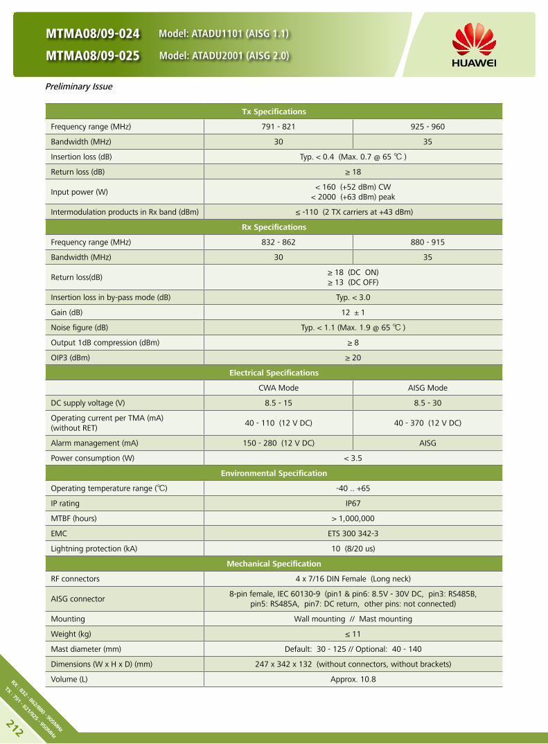
MTMA08/09-024 Model: ATADU1101 (AISG 1.1)
MTMA08/09-025 Model: ATADU2001 (AISG 2.0)
Tx Specifications
Frequency range (MHz) 791 - 821 925 - 960
Bandwidth (MHz) 30 35
Insertion loss (dB) Typ. < 0.4 (Max. 0.7 @ 65 )
Return loss (dB) ≥ 18
Input power (W) < 160 (+52 dBm) CW
< 2000 (+63 dBm) peak
Intermodulation products in Rx band (dBm) ≤ -110 (2 TX carriers at +43 dBm)
Rx Specifications
Frequency range (MHz) 832 - 862 880 - 915
Bandwidth (MHz) 30 35
Return loss(dB) ≥ 18 (DC ON)≥ 13 (DC OFF)
Insertion loss in by-pass mode (dB) Typ. < 3.0
Gain (dB) 12 ±1
Noise figure (dB) Typ. < 1.1 (Max. 1.9 @ 65 )
Output 1dB compression (dBm) ≥ 8
OIP3 (dBm) ≥ 20
Electrical Specifications
CWA Mode AISG Mode
DC supply voltage (V) 8.5 - 15 8.5 - 30
Operating current per TMA (mA) (without RET)
40 - 110 (12 V DC) 40 - 370 (12 V DC)
Alarm management (mA) 150 - 280 (12 V DC) AISG
Power consumption (W) < 3.5
Environmental Specification
Operating temperature range () -40 .. +65
IP rating IP67
MTBF (hours) > 1,000,000
EMC ETS 300 342-3
Lightning protection (kA) 10 (8/20 us)
Mechanical Specification
RF connectors 4 x 7/16 DIN Female (Long neck)
AISG connector8-pin female, IEC 60130-9 (pin1 & pin6: 8.5V - 30V DC, pin3: RS485B,
pin5: RS485A, pin7: DC return, other pins: not connected)
Mounting Wall mounting // Mast mounting
Weight (kg) ≤ 11
Mast diameter (mm) Default: 30 - 125 // Optional: 40 - 140
Dimensions (W x H x D) (mm) 247 x 342 x 132 (without connectors, without brackets)
Volume (L) Approx. 10.8
Preliminary Issue
212
RX : 832 - 862/880 - 905MHz
TX : 791 - 821/925 - 950MHz

MTMA08/09-024 Model: ATADU1101 (AISG 1.1)
MTMA08/09-025 Model: ATADU2001 (AISG 2.0)
Any previous catalogue issues become invalid.
Issue: 2013-01-08
HUAWEI TECHNOLOGIES CO., LTD.
Huawei Industrial BaseBantian Longgang
Shenzhen 518129, P.R. ChinaTel: +86-755-28780808
Email: [email protected]
www.huawei.com
Copyright © Huawei Technologies Co., Ltd. 2013. All rights reserved.
THIS DOCUMENT IS FOR INFORMATION PURPOSE ONLY, AND DOSE NOT CONSTITUTE ANY KIND OF WARRANTIES.
Unit: mm
Preliminary Issue
213
RX : 83
2 - 8
62/8
80 - 90
5MHz
TX : 79
1 - 8
21/9
25 - 95
0MHz

The dual multiband tower mounted amplifier (MTMA) is a low-noise amplifier installed near the antenna to satisfy the co-
siting purposes. It helps to improve the signal-to-noise ratio and enhance the receiving sensibility of the BTS system. It
enhances the uplink coverage and improves uplink and downlink imbalance of the base station. It effectively reduces the
transmitting power of cellphones, improves voice and data communication quality.
MTMA08/09-030 Model: ATADU1105 (AISG 1.1)
MTMA08/09-031 Model: ATADU2005 (AISG 2.0)
Product Description
High linearity and low noise performance. y
Balanced LNA design and power failure bypass for high reliability. y
Light weight and compact design. y
Designed for co-siting purposes. y
Wall mounting and mast mounting. y
Built-in lightning protection up to 10 kA. y
Support AISG 1.1 and AISG 2.0 protocol. y
Features
Appearance and Block Diagram
Preliminary Issue
214
RX : 832 - 862/880 - 905MHz
TX : 791 - 821/925 - 950MHz

MTMA08/09-030 Model: ATADU1105 (AISG 1.1)
MTMA08/09-031 Model: ATADU2005 (AISG 2.0)
Tx Specifications
Frequency range (MHz) 791 - 821 925 - 960
Bandwidth (MHz) 30 35
Insertion loss (dB) Typ. < 0.4 (Max. 0.7 @ 65 )
Return loss (dB) ≥ 18
Input power (W) < 160 (+52 dBm) CW
< 2000 (+63 dBm) peak
Intermodulation products in Rx band (dBm) ≤ -110 (2 TX carriers at +43 dBm)
Rx Specifications
Frequency range (MHz) 832 - 862 880 - 915
Bandwidth (MHz) 30 35
Return loss(dB) ≥ 18 (DC ON)≥ 13 (DC OFF)
Insertion loss in by-pass mode (dB) Typ. < 3.0
Gain (dB) 12 ±1
Noise figure (dB) Typ. < 1.1 (Max. 1.9 @ 65 )
Output 1dB compression (dBm) ≥ 8
OIP3 (dBm) ≥ 20
Electrical Specifications
CWA Mode AISG Mode
DC supply voltage (V) 8.5 - 15 8.5 - 30
Operating current per TMA (mA) (without RET)
40 - 110 (12 V DC) 40 - 370 (12 V DC)
Alarm management (mA) 150 - 280 (12 V DC) AISG
Power consumption (W) < 3.5
Environmental Specification
Operating temperature range () -40 .. +65
IP rating IP67
MTBF (hours) > 1,000,000
EMC ETS 300 342-3
Lightning protection (kA) 10 (8/20 us)
Mechanical Specification
RF connectors 6 x 7/16 DIN Female (Long neck)
AISG connector8-pin female, IEC 60130-9 (pin1 & pin6: 8.5V - 30V DC, pin3: RS485B,
pin5: RS485A, pin7: DC return, other pins: not connected)
Mounting Wall mounting // Mast mounting
Weight (kg) ≤ 11
Mast diameter (mm) Default: 30 - 125 // Optional: 40 - 140
Dimensions (W x H x D) (mm) 247 x 342 x 132 (without connectors, without brackets)
Volume (L) Approx. 10.8
Preliminary Issue
215
RX : 83
2 - 8
62/8
80 - 90
5MHz
TX : 79
1 - 8
21/9
25 - 95
0MHz

MTMA08/09-030 Model: ATADU1105 (AISG 1.1)
MTMA08/09-031 Model: ATADU2005 (AISG 2.0)
Any previous catalogue issues become invalid.
Issue: 2013-01-08
HUAWEI TECHNOLOGIES CO., LTD.
Huawei Industrial BaseBantian Longgang
Shenzhen 518129, P.R. ChinaTel: +86-755-28780808
Email: [email protected]
www.huawei.com
Copyright © Huawei Technologies Co., Ltd. 2013. All rights reserved.
THIS DOCUMENT IS FOR INFORMATION PURPOSE ONLY, AND DOSE NOT CONSTITUTE ANY KIND OF WARRANTIES.
Unit: mm
Preliminary Issue
216
RX : 832 - 862/880 - 905MHz
TX : 791 - 821/925 - 950MHz

Product Description
Built-in lightning protection up to 10 kA. y
Can be used as a combiner near the BTS or in a reciprocal y
function near the antenna.
Designed for co-siting purposes and feeder sharing y
Suitable for indoor or outdoor applications. y
Wall or mast mounting. y
Block Diagram
ACOMD2H09
DC-0023-2
Model: ACOMD2H09
217Ba
nd 1 : 79
0 - 8
62M
Hz
Band
2 : 88
0 - 9
60M
Hz

218
Band 1 : 790 - 862MHz
Band 2 : 880 - 960MHz
DC-0023-2
Model: ACOMD2H09
Electrical Properties
Model ACOMD2H09
Pass band (MHz) Band 1 790 - 862
Band 2 880 - 960
Insertion loss* (dB) Port 1 ←→ Port 3 Typ. < 0.3 (790 MHz - 862 MHz)
Port 2 ←→ Port 3 Typ. < 0.25 (880 MHz - 960 MHz)
DC/AISG transparency Port 1 ←→ Port 3 Stop
Port 2 ←→ Port 3 By-pass (max. 2500 mA)
Isolation (dB) > 50
VSWR < 1.28
Input power (W) Port 1, Port 2 < 200
Intermodulation products (dBm) < -110 (3rd order; with 2 x 43 dBm)
Environmental Specification
Operating temperature () -40 .. +65
Application scene Indoor // Outdoor
IP rating IP67
Lightning protection (kA) 10 (8/20 us)
Mechanical Specification
Combiner dimensions (W x H x D) (mm)Double Unit: 180 x 210 x 107
(without connectors, without mounting brackets)
Packing dimensions (W x H x D) (mm) 260 x 365 x 210
Combiner weight (kg) Double Unit: ≤ 6.8
Packing weight (kg) ≤ 7.8
Mounting Wall mounting // Mast mounting
Mast diameter (mm) Default: 40 - 135
Connector 7/16 DIN Female (Long neck)

DC-0023-2
Model: ACOMD2H09
Unit: mm
Any previous catalogue issues become invalid.
Issue: 2012-10-26
HUAWEI TECHNOLOGIES CO., LTD.
Huawei Industrial BaseBantian Longgang
Shenzhen 518129, P.R. ChinaTel: +86-755-28780808
Email: [email protected]
www.huawei.com
Copyright © Huawei Technologies Co., Ltd. 2013. All rights reserved.
THIS DOCUMENT IS FOR INFORMATION PURPOSE ONLY, AND DOSE NOT CONSTITUTE ANY KIND OF WARRANTIES.
219Ba
nd 1 : 79
0 - 8
62M
Hz
Band
2 : 88
0 - 9
60M
Hz

220
Band 1 : 790 - 862MHz
Band 2 : 880 - 960MHz
DC-0013-2
Model: ACOMD2H04
Product Description
Built-in lightning protection up to 10 kA. y
Can be used as a combiner near the BTS or in a reciprocal y
function near the antenna.
Designed for co-siting purposes and feeder sharing y
Suitable for indoor or outdoor applications. y
Wall or mast mounting. y
Block Diagram
ACOMD2H04

Electrical Properties
Model ACOMD2H04
Pass band (MHz) Band 1 790 - 862
Band 2 880 - 960
Insertion loss* (dB) Port 1 ←→ Port 3 Typ. < 0.3 (790 MHz - 862 MHz)
Port 2 ←→ Port 3 Typ. < 0.25 (880 MHz - 960 MHz)
DC/AISG transparency Port 1 ←→ Port 3 Stop
Port 2 ←→ Port 3 By-pass (max. 2500 mA)
Isolation (dB) > 50
VSWR < 1.28
Input power (W) Port 1, Port 2 < 200
Intermodulation products (dBm) < -117 (3rd order; with 2 x 43 dBm)
Environmental Specification
Operating temperature () -40 .. +65
Application scene Indoor // outdoor
IP rating IP67
Lightning protection (kA) 10 (8/20 us)
Mechanical Specification
Combiner dimensions (W x H x D) (mm)Double Unit: 180 x 210 x 107
(without connectors, without mounting brackets)
Packing dimensions (W x H x D) (mm) 260 x 365 x 210
Combiner weight (kg) Double Unit: ≤ 6.8
Packing weight (kg) ≤ 7.8
Mounting Wall mounting // Mast mounting
Mast diameter (mm) Default: 40 - 135
Connector 7/16 DIN Female (Long neck)
DC-0013-2
Model: ACOMD2H04
221Ba
nd 1 : 79
0 - 8
62M
Hz
Band
2 : 88
0 - 9
60M
Hz

DC-0013-2
Model: ACOMD2H04
Unit: mm
Any previous catalogue issues become invalid.
Issue: 2012-10-26
HUAWEI TECHNOLOGIES CO., LTD.
Huawei Industrial BaseBantian Longgang
Shenzhen 518129, P.R. ChinaTel: +86-755-28780808
Email: [email protected]
www.huawei.com
Copyright © Huawei Technologies Co., Ltd. 2013. All rights reserved.
THIS DOCUMENT IS FOR INFORMATION PURPOSE ONLY, AND DOSE NOT CONSTITUTE ANY KIND OF WARRANTIES.
222
Band 1 : 790 - 862MHz
Band 2 : 880 - 960MHz

Product Description
Built-in lightning protection up to 10 kA. y
Can be used as a combiner near the BTS or in a reciprocal y
function near the antenna.
Designed for co-siting purposes. y
Feeder sharing available. y
Suitable for indoor or outdoor applications. y
Wall or mast mounting. y
Block Diagram
ACOMD2H18
DC-0037-2
Model: ACOMD2H18
Preliminary Issue
223Ba
nd 1 : 79
0 - 8
62M
Hz
Band
2 : 88
0 - 9
60M
Hz
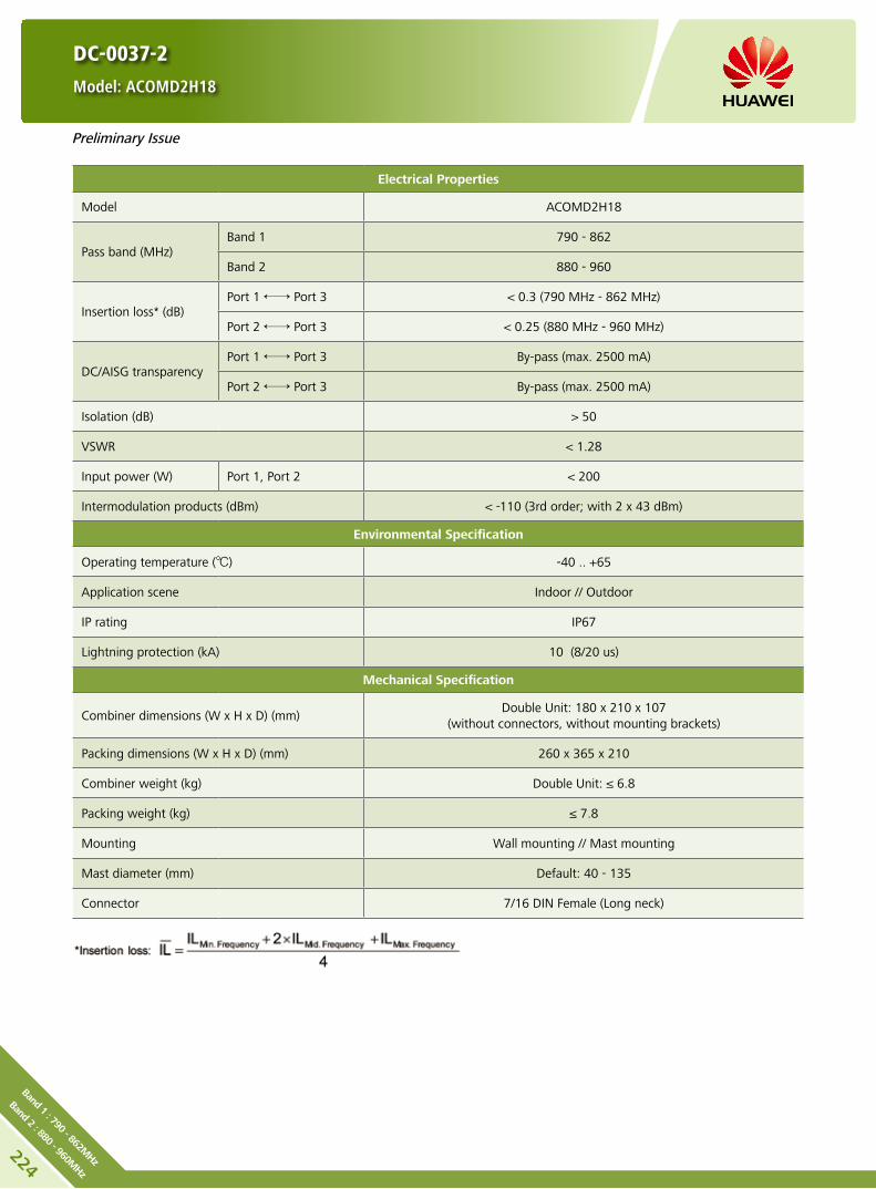
224
Band 1 : 790 - 862MHz
Band 2 : 880 - 960MHz
Electrical Properties
Model ACOMD2H18
Pass band (MHz) Band 1 790 - 862
Band 2 880 - 960
Insertion loss* (dB) Port 1 ←→ Port 3 < 0.3 (790 MHz - 862 MHz)
Port 2 ←→ Port 3 < 0.25 (880 MHz - 960 MHz)
DC/AISG transparency Port 1 ←→ Port 3 By-pass (max. 2500 mA)
Port 2 ←→ Port 3 By-pass (max. 2500 mA)
Isolation (dB) > 50
VSWR < 1.28
Input power (W) Port 1, Port 2 < 200
Intermodulation products (dBm) < -110 (3rd order; with 2 x 43 dBm)
Environmental Specification
Operating temperature () -40 .. +65
Application scene Indoor // Outdoor
IP rating IP67
Lightning protection (kA) 10 (8/20 us)
Mechanical Specification
Combiner dimensions (W x H x D) (mm)Double Unit: 180 x 210 x 107
(without connectors, without mounting brackets)
Packing dimensions (W x H x D) (mm) 260 x 365 x 210
Combiner weight (kg) Double Unit: ≤ 6.8
Packing weight (kg) ≤ 7.8
Mounting Wall mounting // Mast mounting
Mast diameter (mm) Default: 40 - 135
Connector 7/16 DIN Female (Long neck)
DC-0037-2
Model: ACOMD2H18
Preliminary Issue

DC-0037-2
Model: ACOMD2H18
Unit: mm
Any previous catalogue issues become invalid.
Issue: 2013-01-08
HUAWEI TECHNOLOGIES CO., LTD.
Huawei Industrial BaseBantian Longgang
Shenzhen 518129, P.R. ChinaTel: +86-755-28780808
Email: [email protected]
www.huawei.com
Copyright © Huawei Technologies Co., Ltd. 2013. All rights reserved.
THIS DOCUMENT IS FOR INFORMATION PURPOSE ONLY, AND DOSE NOT CONSTITUTE ANY KIND OF WARRANTIES.
Preliminary Issue
225Ba
nd 1 : 79
0 - 8
62M
Hz
Band
2 : 88
0 - 9
60M
Hz

226
Band 1 : 790 - 862MHz
Band 2 : 880 - 960MHz
DC-0029-2
Model: ACOMD2H15
Product Description
Built-in lightning protection up to 10 kA. y
Can be used as a combiner near the BTS or in a reciprocal y
function near the antenna.
Designed for co-siting purposes. y
Feeder sharing available. y
Suitable for indoor or outdoor applications. y
Wall or mast mounting. y
Block Diagram
ACOMD2H15
Preliminary Issue

DC-0029-2
Model: ACOMD2H15
Preliminary Issue
Electrical Properties
Model ACOMD2H15
Pass band (MHz) Band 1 790 - 862
Band 2 880 - 960
Insertion loss* (dB) Port 1 ←→ Port 3 < 0.3 (790 MHz - 862 MHz)
Port 2 ←→ Port 3 < 0.25 (880 MHz - 960 MHz)
DC/AISG transparency Port 1 ←→ Port 3 By-pass (max. 2500 mA)
Port 2 ←→ Port 3 By-pass (max. 2500 mA)
Isolation (dB) > 50
VSWR < 1.24
Input power (W) Port 1, Port 2 < 200
Intermodulation products (dBm) < -117 (3rd order; with 2 x 43 dBm)
Environmental Specification
Operating temperature () -40 .. +65
Application scene Indoor // Outdoor
IP rating IP67
Lightning protection (kA) 10 (8/20 us)
Mechanical Specification
Connector 7/16 female (long neck)
Mounting Wall mounting // Mast mounting
Weight (kg) Double Unit: ≤ 7
Mast diameter (mm) Default: 40 - 135
Dimensions (W x H x D) (mm)Double Unit: 180 x 210 x 107
(without connectors, without mounting brackets)
227Ba
nd 1 : 79
0 - 8
62M
Hz
Band
2 : 88
0 - 9
60M
Hz

DC-0029-2
Model: ACOMD2H15
Unit: mm
Any previous catalogue issues become invalid.
Issue: 2013-01-08
HUAWEI TECHNOLOGIES CO., LTD.
Huawei Industrial BaseBantian Longgang
Shenzhen 518129, P.R. ChinaTel: +86-755-28780808
Email: [email protected]
www.huawei.com
Copyright © Huawei Technologies Co., Ltd. 2013. All rights reserved.
THIS DOCUMENT IS FOR INFORMATION PURPOSE ONLY, AND DOSE NOT CONSTITUTE ANY KIND OF WARRANTIES.
Preliminary Issue
228
Band 1 : 790 - 862MHz
Band 2 : 880 - 960MHz

Preliminary Issue
Product Description
Built-in lightning protection up to 10 kA. y
Can be used as a combiner near the BTS or in a reciprocal y
function near the antenna.
Designed for co-siting purposes. y
Feeder sharing available. y
Suitable for indoor or outdoor applications. y
Wall or mast mounting. y
Block Diagram
ACOMD2H14
DC-0027-2
Model: ACOMD2H14
229Ba
nd 1 : 79
0 - 8
62M
Hz
Band
2 : 88
0 - 2
200M
Hz
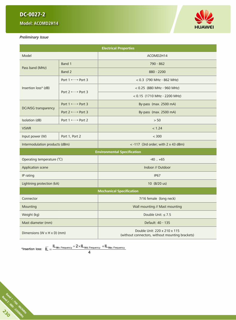
230
Band 1 : 790 - 862MHz
Band 2 : 880 - 2200MHz
Preliminary Issue
DC-0027-2
Model: ACOMD2H14
Electrical Properties
Model ACOMD2H14
Pass band (MHz) Band 1 790 - 862
Band 2 880 - 2200
Insertion loss* (dB)
Port 1 ←→ Port 3 < 0.3 (790 MHz - 862 MHz)
Port 2 ←→ Port 3 < 0.25 (880 MHz - 960 MHz)
< 0.15 (1710 MHz - 2200 MHz)
DC/AISG transparency Port 1 ←→ Port 3 By-pass (max. 2500 mA)
Port 2 ←→ Port 3 By-pass (max. 2500 mA)
Isolation (dB) Port 1 ←→ Port 2 > 50
VSWR < 1.24
Input power (W) Port 1, Port 2 < 300
Intermodulation products (dBm) < -117 (3rd order; with 2 x 43 dBm)
Environmental Specification
Operating temperature () -40 .. +65
Application scene Indoor // Outdoor
IP rating IP67
Lightning protection (kA) 10 (8/20 us)
Mechanical Specification
Connector 7/16 female (long neck)
Mounting Wall mounting // Mast mounting
Weight (kg) Double Unit: ≤ 7.5
Mast diameter (mm) Default: 40 - 135
Dimensions (W x H x D) (mm)Double Unit: 220 x 210 x 115
(without connectors, without mounting brackets)

Preliminary Issue
DC-0027-2
Model: ACOMD2H14
Unit: mm
Any previous catalogue issues become invalid.
Issue: 2013-01-08
HUAWEI TECHNOLOGIES CO., LTD.
Huawei Industrial BaseBantian Longgang
Shenzhen 518129, P.R. ChinaTel: +86-755-28780808
Email: [email protected]
www.huawei.com
Copyright © Huawei Technologies Co., Ltd. 2013. All rights reserved.
THIS DOCUMENT IS FOR INFORMATION PURPOSE ONLY, AND DOSE NOT CONSTITUTE ANY KIND OF WARRANTIES.
231Ba
nd 1 : 79
0 - 8
62M
Hz
Band
2 : 88
0 - 2
200M
Hz
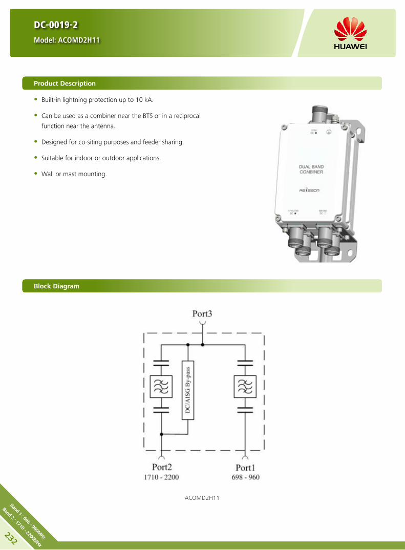
232
Band 1 : 698 - 960MHz
Band 2 : 1710 - 2200MHz
Product Description
Built-in lightning protection up to 10 kA. y
Can be used as a combiner near the BTS or in a reciprocal y
function near the antenna.
Designed for co-siting purposes and feeder sharing y
Suitable for indoor or outdoor applications. y
Wall or mast mounting. y
Block Diagram
ACOMD2H11
DC-0019-2
Model: ACOMD2H11

Electrical Properties
Model ACOMD2H11
Pass band (MHz) Band 1 698 - 960
Band 2 1710 - 2200
Insertion loss* (dB) Port 1 ←→ Port 3 Typ. < 0.15 (698 MHz - 960 MHz)
Port 2 ←→ Port 3 Typ. < 0.15 (1710 MHz - 2200 MHz)
DC/AISG transparency Port 1 ←→ Port 3 Stop
Port 2 ←→ Port 3 By-pass (max. 2500 mA)
Isolation (dB) > 40
VSWR < 1.28
Input power (W) Port 1, Port 2 < 300
Intermodulation products (dBm) < -110 (3rd order; with 2 x 43 dBm)
Environmental Specification
Operating temperature () -40 .. +65
Application scene Indoor // Outdoor
IP rating IP67
Lightning protection (kA) 10 (8/20 us)
Mechanical Specification
Combiner dimensions (W x H x D) (mm)Double Unit: 130 x 190 x 105
(without connectors, without mounting brackets)
Packing dimensions (W x H x D) (mm) 265 x 415 x 245
Combiner weight (kg) Double Unit: ≤ 4.3
Packing weight (kg) ≤ 5.4
Mounting Wall mounting // Mast mounting
Mast diameter (mm) Default: 40 - 135
Connector 7/16 DIN Female (Long neck)
DC-0019-2
Model: ACOMD2H11
233Ba
nd 1 : 69
8 - 9
60M
Hz
Band
2 : 17
10 - 22
00M
Hz

DC-0019-2
Model: ACOMD2H11
Unit: mm
Any previous catalogue issues become invalid.
Issue: 2012-10-26
HUAWEI TECHNOLOGIES CO., LTD.
Huawei Industrial BaseBantian Longgang
Shenzhen 518129, P.R. ChinaTel: +86-755-28780808
Email: [email protected]
www.huawei.com
Copyright © Huawei Technologies Co., Ltd. 2013. All rights reserved.
THIS DOCUMENT IS FOR INFORMATION PURPOSE ONLY, AND DOSE NOT CONSTITUTE ANY KIND OF WARRANTIES.
234
Band 1 : 698 - 960MHz
Band 2 : 1710 - 2200MHz

DC-0017-2
Model: ACOMD2H10
Product Description
Built-in lightning protection up to 10 kA. y
Can be used as a combiner near the BTS or in a reciprocal y
function near the antenna.
Designed for co-siting purposes and feeder sharing y
Suitable for indoor or outdoor applications. y
Wall or mast mounting. y
Block Diagram
ACOMD2H10
235Ba
nd 1 : 69
8 - 9
60M
Hz
Band
2 : 17
10 - 22
00M
Hz
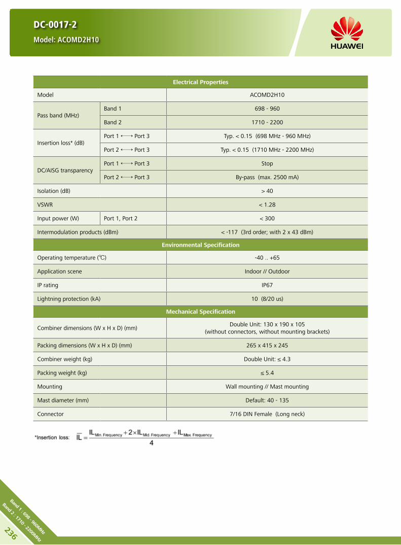
236
Band 1 : 698 - 960MHz
Band 2 : 1710 - 2200MHz
DC-0017-2
Model: ACOMD2H10
Electrical Properties
Model ACOMD2H10
Pass band (MHz) Band 1 698 - 960
Band 2 1710 - 2200
Insertion loss* (dB) Port 1 ←→ Port 3 Typ. < 0.15 (698 MHz - 960 MHz)
Port 2 ←→ Port 3 Typ. < 0.15 (1710 MHz - 2200 MHz)
DC/AISG transparency Port 1 ←→ Port 3 Stop
Port 2 ←→ Port 3 By-pass (max. 2500 mA)
Isolation (dB) > 40
VSWR < 1.28
Input power (W) Port 1, Port 2 < 300
Intermodulation products (dBm) < -117 (3rd order; with 2 x 43 dBm)
Environmental Specification
Operating temperature () -40 .. +65
Application scene Indoor // Outdoor
IP rating IP67
Lightning protection (kA) 10 (8/20 us)
Mechanical Specification
Combiner dimensions (W x H x D) (mm)Double Unit: 130 x 190 x 105
(without connectors, without mounting brackets)
Packing dimensions (W x H x D) (mm) 265 x 415 x 245
Combiner weight (kg) Double Unit: ≤ 4.3
Packing weight (kg) ≤ 5.4
Mounting Wall mounting // Mast mounting
Mast diameter (mm) Default: 40 - 135
Connector 7/16 DIN Female (Long neck)
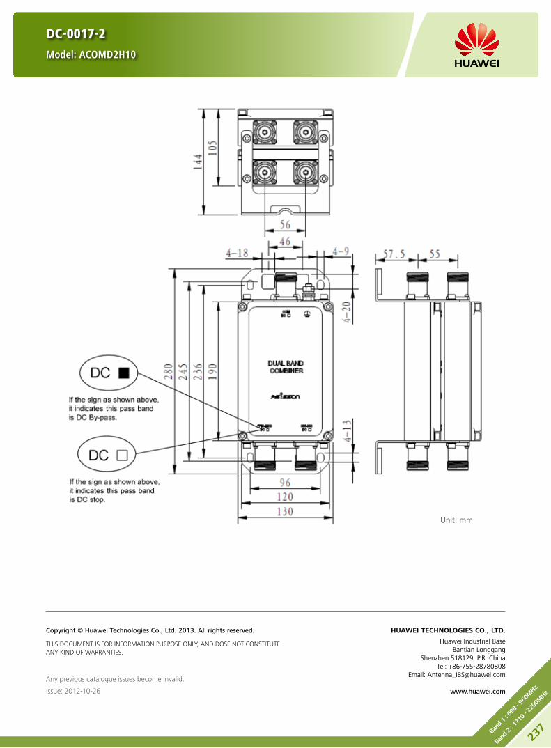
DC-0017-2
Model: ACOMD2H10
Unit: mm
Any previous catalogue issues become invalid.
Issue: 2012-10-26
HUAWEI TECHNOLOGIES CO., LTD.
Huawei Industrial BaseBantian Longgang
Shenzhen 518129, P.R. ChinaTel: +86-755-28780808
Email: [email protected]
www.huawei.com
Copyright © Huawei Technologies Co., Ltd. 2013. All rights reserved.
THIS DOCUMENT IS FOR INFORMATION PURPOSE ONLY, AND DOSE NOT CONSTITUTE ANY KIND OF WARRANTIES.
237Ba
nd 1 : 69
8 - 9
60M
Hz
Band
2 : 17
10 - 22
00M
Hz

238
Band 1 : 698 - 960MHz
Band 2 : 1710 - 2200MHz
Product Description
Built-in lightning protection up to 10 kA. y
Can be used as a combiner near the BTS or in a reciprocal y
function near the antenna.
Designed for co-siting purposes. y
Feeder sharing available. y
Suitable for indoor or outdoor applications. y
Wall or mast mounting. y
Block Diagram
ACOMD2H19
DC-0038-2
Model: ACOMD2H19
Preliminary Issue

Electrical Properties
Model ACOMD2H19
Pass band (MHz) Band 1 698 - 960
Band 2 1710 - 2200
Insertion loss* (dB) Port 1 ←→ Port 3 < 0.15 (698 MHz - 960 MHz)
Port 2 ←→ Port 3 < 0.15 (1710 MHz - 2200 MHz)
DC/AISG transparency Port 1 ←→ Port 3 By-pass (max. 2500 mA)
Port 2 ←→ Port 3 By-pass (max. 2500 mA)
Isolation (dB) > 40
VSWR < 1.28
Input power (W) Port 1, Port 2 < 300
Intermodulation products (dBm) < -110 (3rd order; with 2 x 43 dBm)
Environmental Specification
Operating temperature () -40 .. +65
Application scene Indoor // Outdoor
IP rating IP67
Lightning protection (kA) 10 (8/20 us)
Mechanical Specification
Combiner dimensions (W x H x D) (mm)Double Unit: 130 x 190 x 105
(without connectors, without mounting brackets)
Packing dimensions (W x H x D) (mm) 265 x 415 x 245
Combiner weight (kg) Double Unit: ≤ 4.3
Packing weight (kg) ≤ 5.4
Mounting Wall mounting // Mast mounting
Mast diameter (mm) Default: 40 - 135
Connector 7/16 DIN Female (Long neck)
DC-0038-2
Model: ACOMD2H19
Preliminary Issue
239Ba
nd 1 : 69
8 - 9
60M
Hz
Band
2 : 17
10 - 22
00M
Hz

DC-0038-2
Model: ACOMD2H19
Unit: mm
Any previous catalogue issues become invalid.
Issue: 2013-01-08
HUAWEI TECHNOLOGIES CO., LTD.
Huawei Industrial BaseBantian Longgang
Shenzhen 518129, P.R. ChinaTel: +86-755-28780808
Email: [email protected]
www.huawei.com
Copyright © Huawei Technologies Co., Ltd. 2013. All rights reserved.
THIS DOCUMENT IS FOR INFORMATION PURPOSE ONLY, AND DOSE NOT CONSTITUTE ANY KIND OF WARRANTIES.
Preliminary Issue
240
Band 1 : 698 - 960MHz
Band 2 : 1710 - 2200MHz

Product Description
Built-in lightning protection up to 10 kA. y
Can be used as a combiner near the BTS or in a reciprocal y
function near the antenna.
Designed for co-siting purposes and feeder sharing y
Suitable for indoor or outdoor applications. y
Wall or mast mounting. y
Block Diagram
ACOMD2H13
DC-0020-2
Model: ACOMD2H13
241Ba
nd 1 : 69
8 - 9
60M
Hz
Band
2 : 24
90 - 27
00M
Hz

242
Band 1 : 698 - 960MHz
Band 2 : 2490 - 2700MHz
Electrical Properties
Model ACOMD2H12
Pass band (MHz) Band 1 698 - 960
Band 2 2490 - 2700
Insertion loss* (dB) Port 1 ←→ Port 3 Typ. < 0.15 (698 MHz - 960 MHz)
Port 2 ←→ Port 3 Typ. < 0.15 (2490 MHz - 2700 MHz)
DC/AISG transparency Port 1 ←→ Port 3 Stop
Port 2 ←→ Port 3 By-pass (max. 2500 mA)
Isolation (dB) > 45
VSWR < 1.28
Input power (W) Port 1, Port 2 < 300
Intermodulation products (dBm) < -110 (3rd order; with 2 x 43 dBm)
Environmental Specification
Operating temperature () -40 .. +65
Application scene Indoor // Outdoor
IP rating IP67
Lightning protection (kA) 10 (8/20 us)
Mechanical Specification
Combiner dimensions (W x H x D) (mm)Double Unit: 130 x 190 x 105
(without connectors, without mounting brackets)
Packing dimensions (W x H x D) (mm) 265 x 415 x 245
Combiner weight (kg) Double Unit: ≤ 4.3
Packing weight (kg) ≤ 5.4
Mounting Wall mounting // Mast mounting
Mast diameter (mm) Default: 40 - 135
Connector 7/16 DIN Female (Long neck)
DC-0020-2
Model: ACOMD2H13

DC-0020-2
Model: ACOMD2H13
Unit: mm
Any previous catalogue issues become invalid.
Issue: 2012-10-26
HUAWEI TECHNOLOGIES CO., LTD.
Huawei Industrial BaseBantian Longgang
Shenzhen 518129, P.R. ChinaTel: +86-755-28780808
Email: [email protected]
www.huawei.com
Copyright © Huawei Technologies Co., Ltd. 2013. All rights reserved.
THIS DOCUMENT IS FOR INFORMATION PURPOSE ONLY, AND DOSE NOT CONSTITUTE ANY KIND OF WARRANTIES.
243Ba
nd 1 : 69
8 - 9
60M
Hz
Band
2 : 24
90 - 27
00M
Hz
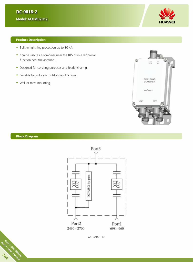
244
Band 1 : 698 - 960MHz
Band 2 : 2490 - 2700MHz
DC-0018-2
Model: ACOMD2H12
Product Description
Built-in lightning protection up to 10 kA. y
Can be used as a combiner near the BTS or in a reciprocal y
function near the antenna.
Designed for co-siting purposes and feeder sharing y
Suitable for indoor or outdoor applications. y
Wall or mast mounting. y
Block Diagram
ACOMD2H12

DC-0018-2
Model: ACOMD2H12
Electrical Properties
Model ACOMD2H12
Pass band (MHz) Band 1 698 - 960
Band 2 2490 - 2700
Insertion loss* (dB) Port 1 ←→ Port 3 Typ. < 0.15 (698 MHz - 960 MHz)
Port 2 ←→ Port 3 Typ. < 0.15 (2490 MHz - 2700 MHz)
DC/AISG transparency Port 1 ←→ Port 3 Stop
Port 2 ←→ Port 3 By-pass (max. 2500 mA)
Isolation (dB) > 45
VSWR < 1.28
Input power (W) Port 1, Port 2 < 300
Intermodulation products (dBm) < -117 (3rd order; with 2 x 43 dBm)
Environmental Specification
Operating temperature () -40 .. +65
Application scene Indoor // Outdoor
IP rating IP67
Lightning protection (kA) 10 (8/20 us)
Mechanical Specification
Combiner dimensions (W x H x D) (mm)Double Unit: 130 x 190 x 105
(without connectors, without mounting brackets)
Packing dimensions (W x H x D) (mm) 265 x 415 x 245
Combiner weight (kg) Double Unit: ≤ 4.3
Packing weight (kg) ≤ 5.4
Mounting Wall mounting // Mast mounting
Mast diameter (mm) Default: 40 - 135
Connector 7/16 DIN Female (Long neck)
245Ba
nd 1 : 69
8 - 9
60M
Hz
Band
2 : 24
90 - 27
00M
Hz

DC-0018-2
Model: ACOMD2H12
Unit: mm
Any previous catalogue issues become invalid.
Issue: 2012-10-26
HUAWEI TECHNOLOGIES CO., LTD.
Huawei Industrial BaseBantian Longgang
Shenzhen 518129, P.R. ChinaTel: +86-755-28780808
Email: [email protected]
www.huawei.com
Copyright © Huawei Technologies Co., Ltd. 2013. All rights reserved.
THIS DOCUMENT IS FOR INFORMATION PURPOSE ONLY, AND DOSE NOT CONSTITUTE ANY KIND OF WARRANTIES.
246
Band 1 : 698 - 960MHz
Band 2 : 2490 - 2700MHz
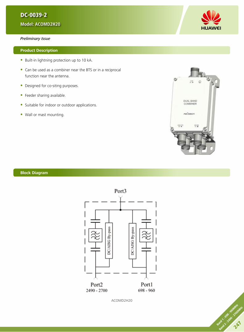
DC-0039-2
Model: ACOMD2H20
Product Description
Built-in lightning protection up to 10 kA. y
Can be used as a combiner near the BTS or in a reciprocal y
function near the antenna.
Designed for co-siting purposes. y
Feeder sharing available. y
Suitable for indoor or outdoor applications. y
Wall or mast mounting. y
Block Diagram
ACOMD2H20
Preliminary Issue
247Ba
nd 1 : 69
8 - 9
60M
Hz
Band
2 : 24
90 - 27
00M
Hz

248
Band 1 : 698 - 960MHz
Band 2 : 2490 - 2700MHz
Electrical Properties
Model ACOMD2H20
Pass band (MHz) Band 1 698 - 960
Band 2 2490 - 2700
Insertion loss* (dB) Port 1 ←→ Port 3 < 0.15 (698 MHz - 960 MHz)
Port 2 ←→ Port 3 < 0.15 (2490 MHz - 2700 MHz)
DC/AISG transparency Port 1 ←→ Port 3 By-pass (max. 2500 mA)
Port 2 ←→ Port 3 By-pass (max. 2500 mA)
Isolation (dB) > 45
VSWR < 1.28
Input power (W) Port 1, Port 2 < 300
Intermodulation products (dBm) < -110 (3rd order; with 2 x 43 dBm)
Environmental Specification
Operating temperature () -40 .. +65
Application scene Indoor // Outdoor
IP rating IP67
Lightning protection (kA) 10 (8/20 us)
Mechanical Specification
Combiner dimensions (W x H x D) (mm)Double Unit: 130 x 190 x 105
(without connectors, without mounting brackets)
Packing dimensions (W x H x D) (mm) 265 x 415 x 245
Combiner weight (kg) Double Unit: ≤ 4.3
Packing weight (kg) ≤ 5.4
Mounting Wall mounting // Mast mounting
Mast diameter (mm) Default: 40 - 135
Connector 7/16 DIN Female (Long neck)
DC-0039-2
Model: ACOMD2H20
Preliminary Issue

DC-0039-2
Model: ACOMD2H20
Unit: mm
Any previous catalogue issues become invalid.
Issue: 2013-01-08
HUAWEI TECHNOLOGIES CO., LTD.
Huawei Industrial BaseBantian Longgang
Shenzhen 518129, P.R. ChinaTel: +86-755-28780808
Email: [email protected]
www.huawei.com
Copyright © Huawei Technologies Co., Ltd. 2013. All rights reserved.
THIS DOCUMENT IS FOR INFORMATION PURPOSE ONLY, AND DOSE NOT CONSTITUTE ANY KIND OF WARRANTIES.
Preliminary Issue
249Ba
nd 1 : 69
8 - 9
60M
Hz
Band
2 : 24
90 - 27
00M
Hz

250
Band 1 : 698 - 960MHz
Band 2 : 1710 - 2700MHz
DC-0010-2
Model: ACOMD2H00
Product Description
Built-in lightning protection up to 10 kA. y
Can be used as a combiner near the BTS or in a reciprocal y
function near the antenna.
Designed for co-siting purposes and feeder sharing y
Suitable for indoor or outdoor applications. y
Wall or mast mounting. y
Block Diagram
ACOMD2H00

Electrical Properties
Model ACOMD2H00
Pass band (MHz) Band 1 698 - 960
Band 2 1710 - 2700
Insertion loss* (dB) Port 1 ←→ Port 3 Typ. < 0.2 (698 MHz - 960 MHz)
Port 2 ←→ Port 3 Typ. < 0.25 (1710 MHz - 2700 MHz)
DC/AISG transparency Port 1 ←→ Port 3 Stop
Port 2 ←→ Port 3 By-pass (max. 2500 mA)
Isolation (dB) > 40
VSWR < 1.28
Input power (W) Port 1, Port 2 < 300
Intermodulation products (dBm) < -117 (3rd order; with 2 x 43 dBm)
Environmental Specification
Operating temperature () -40 .. +65
Application scene Indoor // Outdoor
IP rating IP67
Lightning protection (kA) 10 (8/20 us)
Mechanical Specification
Combiner dimensions (W x H x D) (mm)Double Unit: 130 x 190 x 105
(without connectors, without mounting brackets)
Packing dimensions (W x H x D) (mm) 265 x 415 x 245
Combiner weight (kg) Double Unit: ≤ 4.3
Packing weight (kg) ≤ 5.4
Mounting Wall mounting // Mast mounting
Mast diameter (mm) Default: 40 - 135
Connector 7/16 DIN Female (Long neck)
DC-0010-2
Model: ACOMD2H00
251Ba
nd 1 : 69
8 - 9
60M
Hz
Band
2 : 17
10 - 27
00M
Hz

DC-0010-2
Model: ACOMD2H00
Unit: mm
Any previous catalogue issues become invalid.
Issue: 2012-10-26
HUAWEI TECHNOLOGIES CO., LTD.
Huawei Industrial BaseBantian Longgang
Shenzhen 518129, P.R. ChinaTel: +86-755-28780808
Email: [email protected]
www.huawei.com
Copyright © Huawei Technologies Co., Ltd. 2013. All rights reserved.
THIS DOCUMENT IS FOR INFORMATION PURPOSE ONLY, AND DOSE NOT CONSTITUTE ANY KIND OF WARRANTIES.
252
Band 1 : 698 - 960MHz
Band 2 : 1710 - 2700MHz

DC-0003-2
Model: ACOMD2H02
Product Description
Built-in lightning protection up to 10 kA. y
Can be used as a combiner near the BTS or in a reciprocal y
function near the antenna.
Designed for co-siting purposes and feeder sharing y
Suitable for indoor or outdoor applications. y
Wall or mast mounting. y
Block Diagram
ACOMD2H02
Preliminary Issue
253Ba
nd 1 : 79
0 - 1
880M
Hz
Band
2 : 19
20 - 22
00M
Hz

Electrical Properties
Model ACOMD2H02
Pass band (MHz) Band 1 790 - 1880
Band 2 1920 - 2200
Insertion loss* (dB) Port 1 ←→ Port 3
Typ. < 0.15 (790 MHz - 960 MHz)
Typ. < 0.25 (1710 MHz - 1880 MHz)
Port 2 ←→ Port 3 Typ. < 0.25 (1920 MHz - 2200 MHz)
DC/AISG transparency Port 1 ←→ Port 3 Stop
Port 2 ←→ Port 3 By-pass (max. 2500 mA)
Isolation (dB) > 45
VSWR < 1.28
Input power (W) Port 1, Port 2 < 300
Intermodulation products (dBm) < -110 (3rd order; with 2 x 43 dBm)
Environmental Specification
Operating temperature () -40 .. +65
Application scene Indoor // Outdoor
IP rating IP67
Lightning protection (kA) 10 (8/20 us)
Mechanical Specification
Connector 7/16 DIN Female (long neck)
Mounting Wall mounting // Mast mounting
Weight (kg) Double Unit: ≤ 6
Mast diameter (mm) 40 - 135
Dimensions (W x H x D) (mm) Double Unit: 190 x 154 x 105
(without connectors, without mounting brackets)
DC-0003-2
Model: ACOMD2H02
Preliminary Issue
254
Band 1 : 790 - 1880MHz
Band 2 : 1920 - 2200MHz

DC-0003-2
Model: ACOMD2H02
Unit: mm
Any previous catalogue issues become invalid.
Issue: 2013-01-08
HUAWEI TECHNOLOGIES CO., LTD.
Huawei Industrial BaseBantian Longgang
Shenzhen 518129, P.R. ChinaTel: +86-755-28780808
Email: [email protected]
www.huawei.com
Copyright © Huawei Technologies Co., Ltd. 2013. All rights reserved.
THIS DOCUMENT IS FOR INFORMATION PURPOSE ONLY, AND DOSE NOT CONSTITUTE ANY KIND OF WARRANTIES.
Preliminary Issue
255Ba
nd 1 : 79
0 - 1
880M
Hz
Band
2 : 19
20 - 22
00M
Hz

256
Band 1 : 790 - 1880MHz
Band 2 : 1920 - 2200MHz
Product Description
Built-in lightning protection up to 10 kA. y
Can be used as a combiner near the BTS or in a reciprocal y
function near the antenna.
Designed for co-siting purposes. y
Feeder sharing available. y
Suitable for indoor or outdoor applications. y
Wall or mast mounting. y
Block Diagram
ACOMD2H21
DC-0040-2
Model: ACOMD2H21
Preliminary Issue
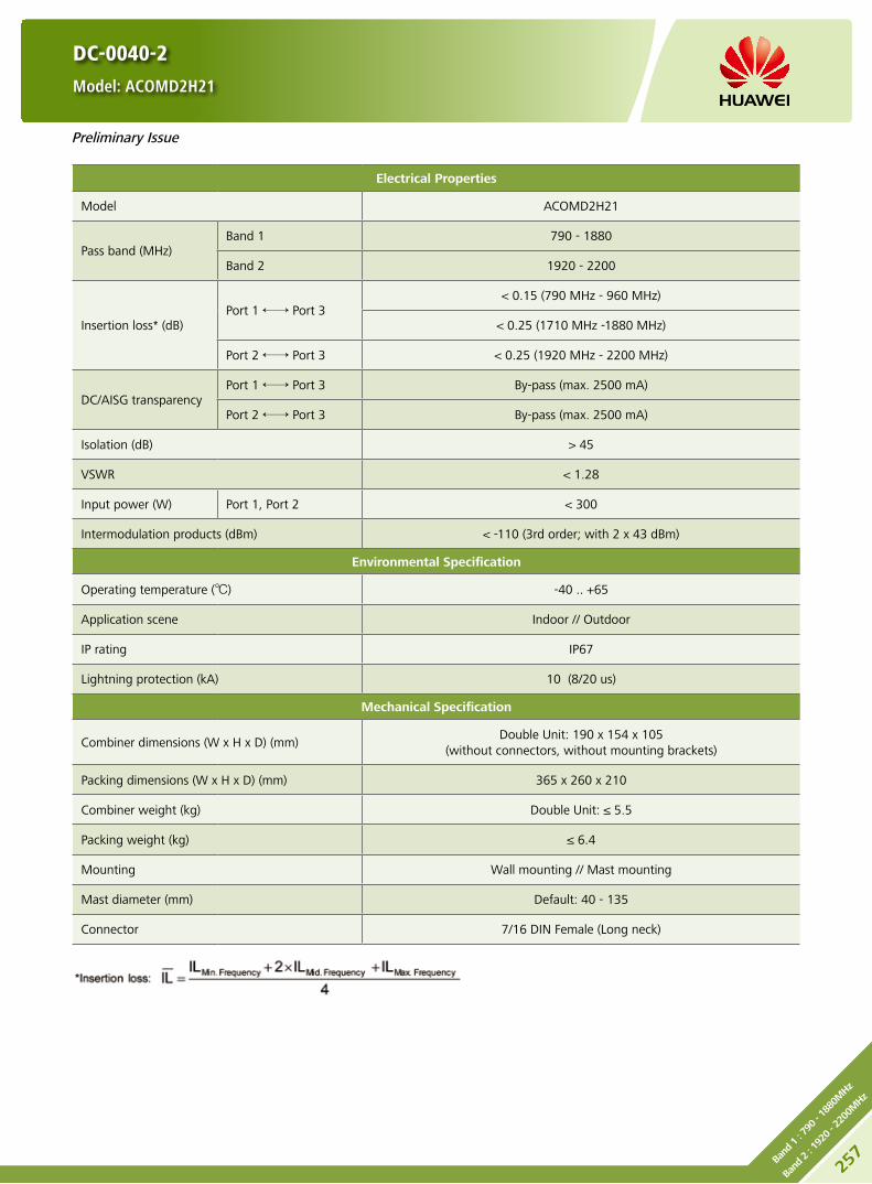
Electrical Properties
Model ACOMD2H21
Pass band (MHz) Band 1 790 - 1880
Band 2 1920 - 2200
Insertion loss* (dB) Port 1 ←→ Port 3
< 0.15 (790 MHz - 960 MHz)
< 0.25 (1710 MHz -1880 MHz)
Port 2 ←→ Port 3 < 0.25 (1920 MHz - 2200 MHz)
DC/AISG transparency Port 1 ←→ Port 3 By-pass (max. 2500 mA)
Port 2 ←→ Port 3 By-pass (max. 2500 mA)
Isolation (dB) > 45
VSWR < 1.28
Input power (W) Port 1, Port 2 < 300
Intermodulation products (dBm) < -110 (3rd order; with 2 x 43 dBm)
Environmental Specification
Operating temperature () -40 .. +65
Application scene Indoor // Outdoor
IP rating IP67
Lightning protection (kA) 10 (8/20 us)
Mechanical Specification
Combiner dimensions (W x H x D) (mm)Double Unit: 190 x 154 x 105
(without connectors, without mounting brackets)
Packing dimensions (W x H x D) (mm) 365 x 260 x 210
Combiner weight (kg) Double Unit: ≤ 5.5
Packing weight (kg) ≤ 6.4
Mounting Wall mounting // Mast mounting
Mast diameter (mm) Default: 40 - 135
Connector 7/16 DIN Female (Long neck)
DC-0040-2
Model: ACOMD2H21
Preliminary Issue
257Ba
nd 1 : 79
0 - 1
880M
Hz
Band
2 : 19
20 - 22
00M
Hz
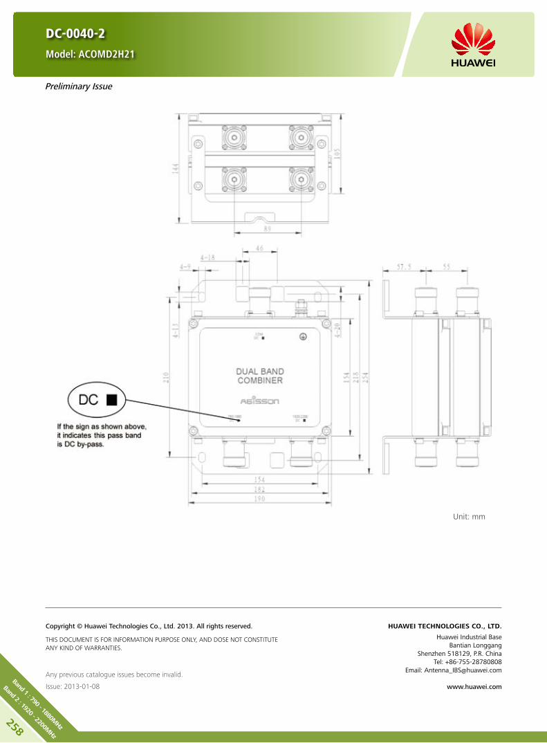
DC-0040-2
Model: ACOMD2H21
Unit: mm
Any previous catalogue issues become invalid.
Issue: 2013-01-08
HUAWEI TECHNOLOGIES CO., LTD.
Huawei Industrial BaseBantian Longgang
Shenzhen 518129, P.R. ChinaTel: +86-755-28780808
Email: [email protected]
www.huawei.com
Copyright © Huawei Technologies Co., Ltd. 2013. All rights reserved.
THIS DOCUMENT IS FOR INFORMATION PURPOSE ONLY, AND DOSE NOT CONSTITUTE ANY KIND OF WARRANTIES.
Preliminary Issue
258
Band 1 : 790 - 1880MHz
Band 2 : 1920 - 2200MHz

DC-0026-2 Model: ACOMD2H06
DC-0022-2 Model: ACOMD2H08
Product Description
Built-in lightning protection up to 10 kA. y
Can be used as a combiner near the BTS or in a reciprocal y
function near the antenna.
Designed for co-siting purposes and feeder sharing y
Suitable for indoor or outdoor applications. y
Wall or mast mounting. y
Block Diagram
ACOMD2H06 ACOMD2H08
259
Band
1 : 17
10 - 18
80M
Hz
Band
2 : 19
20 - 22
00M
Hz

260
Band 1 : 1710 - 1880MHz
Band 2 : 1920 - 2200MHz
DC-0026-2 Model: ACOMD2H06
DC-0022-2 Model: ACOMD2H08
Electrical Properties
Model ACOMD2H06 ACOMD2H08
Pass band (MHz) Band 1 1710 - 1880
Band 2 1920 - 2200
Insertion loss* (dB) Port 1 ←→ Port 3 Typ. < 0.25 (1710 MHz - 1880 MHz)
Port 2 ←→ Port 3 Typ. < 0.25 (1920 MHz - 2200 MHz)
DC/AISG transparency Port 1 ←→ Port 3 Stop By-pass (max. 2500 mA)
Port 2 ←→ Port 3 By-pass (max. 2500 mA) By-pass (max. 2500 mA)
Isolation (dB) > 45
VSWR < 1.28
Input power (W) Port 1, Port 2 < 300
Intermodulation products (dBm) < -110 (3rd order; with 2 x 43 dBm)
Environmental Specification
Operating temperature () -40 .. +65
Application scene Indoor // Outdoor
IP rating IP67
Lightning protection (kA) 10 (8/20 us)
Mechanical Specification
Combiner dimensions (W x H x D) (mm)Double Unit: 160 x 154 x 103
(without connectors, without mounting brackets)
Packing dimensions (W x H x D) (mm) 365 x 260 x 210
Combiner weight (kg) Double Unit: ≤ 4.8
Packing weight (kg) ≤ 5.7
Mounting Wall mounting // Mast mounting
Mast diameter (mm) Default: 40 - 135
Connector 7/16 DIN Female (Long neck)

DC-0026-2 Model: ACOMD2H06
DC-0022-2 Model: ACOMD2H08
Unit: mm
Any previous catalogue issues become invalid.
Issue: 2012-10-26
HUAWEI TECHNOLOGIES CO., LTD.
Huawei Industrial BaseBantian Longgang
Shenzhen 518129, P.R. ChinaTel: +86-755-28780808
Email: [email protected]
www.huawei.com
Copyright © Huawei Technologies Co., Ltd. 2013. All rights reserved.
THIS DOCUMENT IS FOR INFORMATION PURPOSE ONLY, AND DOSE NOT CONSTITUTE ANY KIND OF WARRANTIES.
261
Band
1 : 17
10 - 18
80M
Hz
Band
2 : 19
20 - 22
00M
Hz

262
Band 1 : 1710 - 1880MHz
Band 2 : 1920 - 2200MHz
DC-0012-2 Model: ACOMD2H05
DC-0021-2 Model: ACOMD2H07
Product Description
Built-in lightning protection up to 10 kA. y
Can be used as a combiner near the BTS or in a reciprocal y
function near the antenna.
Designed for co-siting purposes and feeder sharing y
Suitable for indoor or outdoor applications. y
Wall or mast mounting. y
Block Diagram
ACOMD2H05 ACOMD2H07

Electrical Properties
Model ACOMD2H05 ACOMD2H07
Pass band (MHz) Band 1 1710 - 1880
Band 2 1920 - 2200
Insertion loss* (dB) Port 1 ←→ Port 3 Typ. < 0.25 (1710 MHz - 1880 MHz)
Port 2 ←→ Port 3 Typ. < 0.25 (1920 MHz - 2200 MHz)
DC/AISG transparency Port 1 ←→ Port 3 Stop By-pass (max. 2500 mA)
Port 2 ←→ Port 3 By-pass (max. 2500 mA) By-pass (max. 2500 mA)
Isolation (dB) > 45
VSWR < 1.28
Input power (W) Port 1, Port 2 < 300
Intermodulation products (dBm) < -117 (3rd order; with 2 x 43 dBm)
Environmental Specification
Operating temperature () -40 .. +65
Application scene Indoor // Outdoor
IP rating IP67
Lightning protection (kA) 10 (8/20 us)
Mechanical Specification
Combiner dimensions (W x H x D) (mm)Double Unit: 160 x 154 x 103
(without connectors, without mounting brackets)
Packing dimensions (W x H x D) (mm) 365 x 260 x 210
Combiner weight (kg) Double Unit: ≤ 4.8
Packing weight (kg) ≤ 5.7
Mounting Wall mounting // Mast mounting
Mast diameter (mm) Default: 40 - 135
Connector 7/16 DIN Female (Long neck)
DC-0012-2 Model: ACOMD2H05
DC-0021-2 Model: ACOMD2H07
263
Band
1 : 17
10 - 18
80M
Hz
Band
2 : 19
20 - 22
00M
Hz

DC-0012-2 Model: ACOMD2H05
DC-0021-2 Model: ACOMD2H07
Unit: mm
Any previous catalogue issues become invalid.
Issue: 2012-10-26
HUAWEI TECHNOLOGIES CO., LTD.
Huawei Industrial BaseBantian Longgang
Shenzhen 518129, P.R. ChinaTel: +86-755-28780808
Email: [email protected]
www.huawei.com
Copyright © Huawei Technologies Co., Ltd. 2013. All rights reserved.
THIS DOCUMENT IS FOR INFORMATION PURPOSE ONLY, AND DOSE NOT CONSTITUTE ANY KIND OF WARRANTIES.
264
Band 1 : 1710 - 1880MHz
Band 2 : 1920 - 2200MHz

Product Description
Built-in lightning protection up to 10 kA. y
Can be used as a combiner near the BTS or in a reciprocal y
function near the antenna.
Designed for co-siting purposes and feeder sharing y
Suitable for indoor or outdoor applications. y
Wall or mast mounting. y
Block Diagram
ACOMD2L04
DC-0024-2
Model: ACOMD2L04
265
Band
1 : 17
10 - 22
00M
Hz
Band
2 : 24
90 - 27
00M
Hz

266
Band 1 : 1710 - 2200MHz
Band 2 : 2490 - 2700MHz
Electrical Properties
Model ACOMD2L04
Pass band (MHz) Band 1 1710 - 2200
Band 2 2490 - 2700
Insertion loss* (dB) Port 1 ←→ Port 3 Typ. < 0.15 (1710 MHz - 2200 MHz)
Port 2 ←→ Port 3 Typ. < 0.15 (2490 MHz - 2700 MHz)
DC/AISG transparency Port 1 ←→ Port 3 By-pass (max. 2500 mA)
Port 2 ←→ Port 3 Stop
Isolation (dB) > 45
VSWR < 1.28
Input power (W) Port 1, Port 2 < 300
Intermodulation products (dBm) < -110 (3rd order; with 2 x 43 dBm)
Environmental Specification
Operating temperature () -40 .. +65
Application scene Indoor // Outdoor
IP rating IP67
Lightning protection (kA) 10 (8/20 us)
Mechanical Specification
Combiner dimensions (W x H x D) (mm)Double Unit: 126 x 102 x 103
(without connectors, without mounting brackets)
Packing dimensions (W x H x D) (mm) 365 x 260 x 210
Combiner weight (kg) Double Unit: ≤ 3.2
Packing weight (kg) ≤ 4.2
Mounting Wall mounting // Mast mounting
Mast diameter (mm) Default: 40 - 135
Connector 7/16 DIN Female (Long neck)
DC-0024-2
Model: ACOMD2L04
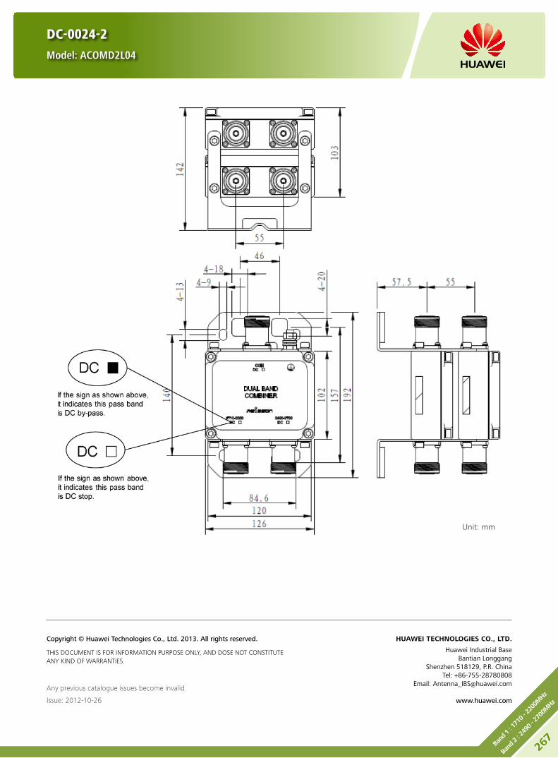
DC-0024-2
Model: ACOMD2L04
Unit: mm
Any previous catalogue issues become invalid.
Issue: 2012-10-26
HUAWEI TECHNOLOGIES CO., LTD.
Huawei Industrial BaseBantian Longgang
Shenzhen 518129, P.R. ChinaTel: +86-755-28780808
Email: [email protected]
www.huawei.com
Copyright © Huawei Technologies Co., Ltd. 2013. All rights reserved.
THIS DOCUMENT IS FOR INFORMATION PURPOSE ONLY, AND DOSE NOT CONSTITUTE ANY KIND OF WARRANTIES.
267
Band
1 : 17
10 - 22
00M
Hz
Band
2 : 24
90 - 27
00M
Hz

268
Band 1 : 1710 - 2200MHz
Band 2 : 2490 - 2700MHz
DC-0006-2
Model: ACOMD2L03
Product Description
Built-in lightning protection up to 10 kA. y
Can be used as a combiner near the BTS or in a reciprocal y
function near the antenna.
Designed for co-siting purposes and feeder sharing y
Suitable for indoor or outdoor applications. y
Wall or mast mounting. y
Block Diagram
ACOMD2L03

DC-0006-2
Model: ACOMD2L03
Electrical Properties
Model ACOMD2L03
Pass band (MHz) Band 1 1710 - 2200
Band 2 2490 - 2700
Insertion loss* (dB) Port 1 ←→ Port 3 Typ. < 0.15 (1710 MHz - 2200 MHz)
Port 2 ←→ Port 3 Typ. < 0.15 (2490 MHz - 2700 MHz)
DC/AISG transparency Port 1 ←→ Port 3 By-pass (max. 2500 mA)
Port 2 ←→ Port 3 Stop
Isolation (dB) > 45
VSWR < 1.28
Input power (W) Port 1, Port 2 < 300
Intermodulation products (dBm) < -117 (3rd order; with 2 x 43 dBm)
Environmental Specification
Operating temperature () -40 .. +65
Application scene Indoor // Outdoor
IP rating IP67
Lightning protection (kA) 10 (8/20 us)
Mechanical Specification
Combiner dimensions (W x H x D) (mm)Double Unit: 126 x 102 x 103
(without connectors, without mounting brackets)
Packing dimensions (W x H x D) (mm) 365 x 260 x 210
Combiner weight (kg) Double Unit: ≤ 3.2
Packing weight (kg) ≤ 4.2
Mounting Wall mounting // Mast mounting
Mast diameter (mm) Default: 40 - 135
Connector 7/16 DIN Female (Long neck)
269
Band
1 : 17
10 - 22
00M
Hz
Band
2 : 24
90 - 27
00M
Hz

DC-0006-2
Model: ACOMD2L03
Unit: mm
Any previous catalogue issues become invalid.
Issue: 2012-10-26
HUAWEI TECHNOLOGIES CO., LTD.
Huawei Industrial BaseBantian Longgang
Shenzhen 518129, P.R. ChinaTel: +86-755-28780808
Email: [email protected]
www.huawei.com
Copyright © Huawei Technologies Co., Ltd. 2013. All rights reserved.
THIS DOCUMENT IS FOR INFORMATION PURPOSE ONLY, AND DOSE NOT CONSTITUTE ANY KIND OF WARRANTIES.
270
Band 1 : 1710 - 2200MHz
Band 2 : 2490 - 2700MHz

Product Description
Built-in lightning protection up to 10 kA. y
Can be used as a combiner near the BTS or in a reciprocal y
function near the antenna.
Designed for co-siting purposes. y
Feeder sharing available. y
Suitable for indoor or outdoor applications. y
Wall or mast mounting. y
Block Diagram
ACOMD2H16
DC-0034-2
Model: ACOMD2H16
Preliminary Issue
271
Band
1 : 17
10 - 22
00M
Hz
Band
2 : 24
90 - 27
00M
Hz

272
Band 1 : 1710 - 2200MHz
Band 2 : 2490 - 2700MHz
Electrical Properties
Model ACOMD2H16
Pass band (MHz) Band 1 1710 - 2200
Band 2 2490 - 2700
Insertion loss* (dB) Port 1 ←→ Port 3 < 0.15 (1710 MHz - 2200 MHz)
Port 2 ←→ Port 3 < 0.15 (2490 MHz - 2700 MHz)
DC/AISG transparency Port 1 ←→ Port 3 By-pass (max. 2500 mA)
Port 2 ←→ Port 3 By-pass (max. 2500 mA)
Isolation (dB) > 45
VSWR < 1.28
Input power (W) Port 1, Port 2 < 300
Intermodulation products (dBm) < -110 (3rd order; with 2 x 43 dBm)
Environmental Specification
Operating temperature () -40 .. +65
Application scene Indoor // Outdoor
IP rating IP67
Lightning protection (kA) 10 (8/20 us)
Mechanical Specification
Combiner dimensions (W x H x D) (mm)Double Unit: 126 x 102 x 103
(without connectors, without mounting brackets)
Packing dimensions (W x H x D) (mm) 365 x 260 x 210
Combiner weight (kg) Double Unit: ≤ 3.2
Packing weight (kg) ≤ 4.2
Mounting Wall mounting // Mast mounting
Mast diameter (mm) Default: 40 - 135
Connector 7/16 DIN Female (Long neck)
DC-0034-2
Model: ACOMD2H16
Preliminary Issue

DC-0034-2
Model: ACOMD2H16
Unit: mm
Any previous catalogue issues become invalid.
Issue: 2013-01-08
HUAWEI TECHNOLOGIES CO., LTD.
Huawei Industrial BaseBantian Longgang
Shenzhen 518129, P.R. ChinaTel: +86-755-28780808
Email: [email protected]
www.huawei.com
Copyright © Huawei Technologies Co., Ltd. 2013. All rights reserved.
THIS DOCUMENT IS FOR INFORMATION PURPOSE ONLY, AND DOSE NOT CONSTITUTE ANY KIND OF WARRANTIES.
Preliminary Issue
273
Band
1 : 17
10 - 22
00M
Hz
Band
2 : 24
90 - 27
00M
Hz

274
Band 1 : 2500 - 2540/2620 - 2660MHz
Band 2 : 2575 - 2595MHz
DC-0030-2
Model: ACOMD2L05
Product Description
Built-in lightning protection up to 10 kA. y
Can be used as a combiner near the BTS or in a reciprocal y
function near the antenna.
Designed for co-siting purposes. y
Feeder sharing available. y
Suitable for indoor or outdoor applications. y
Wall or mast mounting. y
Block Diagram
ACOMD2L05
Preliminary Issue

DC-0030-2
Model: ACOMD2L05
Electrical Properties
Pass band (MHz)
Band 1 2500 - 2540
Band 2 2620 - 2660
Band 3 2575 - 2595
Insertion loss* (dB)
Band 1 < 0.6 (2500 MHz - 2540 MHz)
Band 2 < 0.6 (2620 MHz - 2660 MHz)
Band 3 < 0.65 (2575 MHz - 2595 MHz)
DC/AISG transparencyPort 1 ←→ Port 3 By-pass (max. 2500 mA)
Port 2 ←→ Port 3 Stop
Isolation (dB) < 60
VSWR < 1.28
Input power (W) Port 1, Port 2 < 250
Intermodulation products (dBm) < -110 (3rd order; with 2 x 43 dBm)
Environmental Specification
Operating temperature () -40 .. +65
Application scene Indoor // outdoor
IP rating IP67
Lightning protection (kA) 10 (8/20 us)
Mechanical Specification
Connector 7/16 DIN Female (Long neck)
Mounting Wall mounting // Mast mounting
Weight (kg) Double Unit: ≤ 7.8
Mast diameter (mm) Default: 40 - 135
Dimensions (W x H x D) (mm)Double Unit: 250 x 176 x 103
(without connectors, without mounting brackets)
Preliminary Issue
275
Band
1 : 25
00 - 25
40/2
620 - 2
660M
Hz
Band
2 : 25
75 - 25
95M
Hz

DC-0030-2
Model: ACOMD2L05
Unit: mm
Any previous catalogue issues become invalid.
Issue: 2013-01-08
HUAWEI TECHNOLOGIES CO., LTD.
Huawei Industrial BaseBantian Longgang
Shenzhen 518129, P.R. ChinaTel: +86-755-28780808
Email: [email protected]
www.huawei.com
Copyright © Huawei Technologies Co., Ltd. 2013. All rights reserved.
THIS DOCUMENT IS FOR INFORMATION PURPOSE ONLY, AND DOSE NOT CONSTITUTE ANY KIND OF WARRANTIES.
Preliminary Issue
276
Band 1 : 2500 - 2540/2620 - 2660MHz
Band 2 : 2575 - 2595MHz

4-DC-X0Y0-WL1
Model: ACOMD2H25
Product Description
Built-in lightning protection up to 10 kA. y
Can be used as a combiner near the BTS or in a reciprocal y
function near the antenna.
Designed for co-siting purposes. y
Feeder sharing available. y
Suitable for indoor or outdoor applications. y
Wall or mast mounting. y
Block Diagram
4-DC-X0Y0-WL1
277
Band
1 : 26
14 - 26
24M
Hz
Band
2 : 25
82 - 26
02M
Hz

278
Band 1 : 2614 - 2624MHz
Band 2 : 2582 - 2602MHz
4-DC-X0Y0-WL1
Model: ACOMD2H25
Electrical Properties
Model ACOMD2H25
Pass band (MHz)Band LTE TDD 2582 - 2602
Band WiMAX 2614 - 2624
Insertion loss* (dB)Port LTE TDD ←→ Port COM < 0.15 (790 MHz - 960 MHz)
Port WiMAX ←→ Port COM < 0.25 (1710 MHz - 1880 MHz)
DC/AISG transparencyPort LTE TDD ←→ Port COM Stop
Port WiMAX ←→ Port COM Stop
Isolation (dB) > 30
VSWR < 1.25
Input power (W) Port LTE TDD, Port WiMAX < 60
Intermodulation products (dBm) < -97 (3rd order; with 2 x 43 dBm)
Environmental Specification
Operating temperature () -40 … +65
Application scene Indoor // Outdoor
IP rating IP67
Lightning protection (kA) 10 (8/20 us)
Mechanical Specification
Combiner dimensions (W x H x D) (mm)361 x 158.2 x 120
(with connectors, with mounting brackets)
Packing dimensions (W x H x D) (mm) 485 x 440 x 242
Combiner weight (kg) ≤ 5.7
Packing weight (kg) ≤ 7.0
Mounting Wall mounting // Mast mounting
Mast diameter (mm) Default: 30 - 127
Connector N-Female

4-DC-X0Y0-WL1
Model: ACOMD2H25
Unit: mm
Any previous catalogue issues become invalid.
Issue: 2012-10-26
HUAWEI TECHNOLOGIES CO., LTD.
Huawei Industrial BaseBantian Longgang
Shenzhen 518129, P.R. ChinaTel: +86-755-28780808
Email: [email protected]
www.huawei.com
Copyright © Huawei Technologies Co., Ltd. 2013. All rights reserved.
THIS DOCUMENT IS FOR INFORMATION PURPOSE ONLY, AND DOSE NOT CONSTITUTE ANY KIND OF WARRANTIES.
279
Band
1 : 26
14 - 26
24M
Hz
Band
2 : 25
82 - 26
02M
Hz
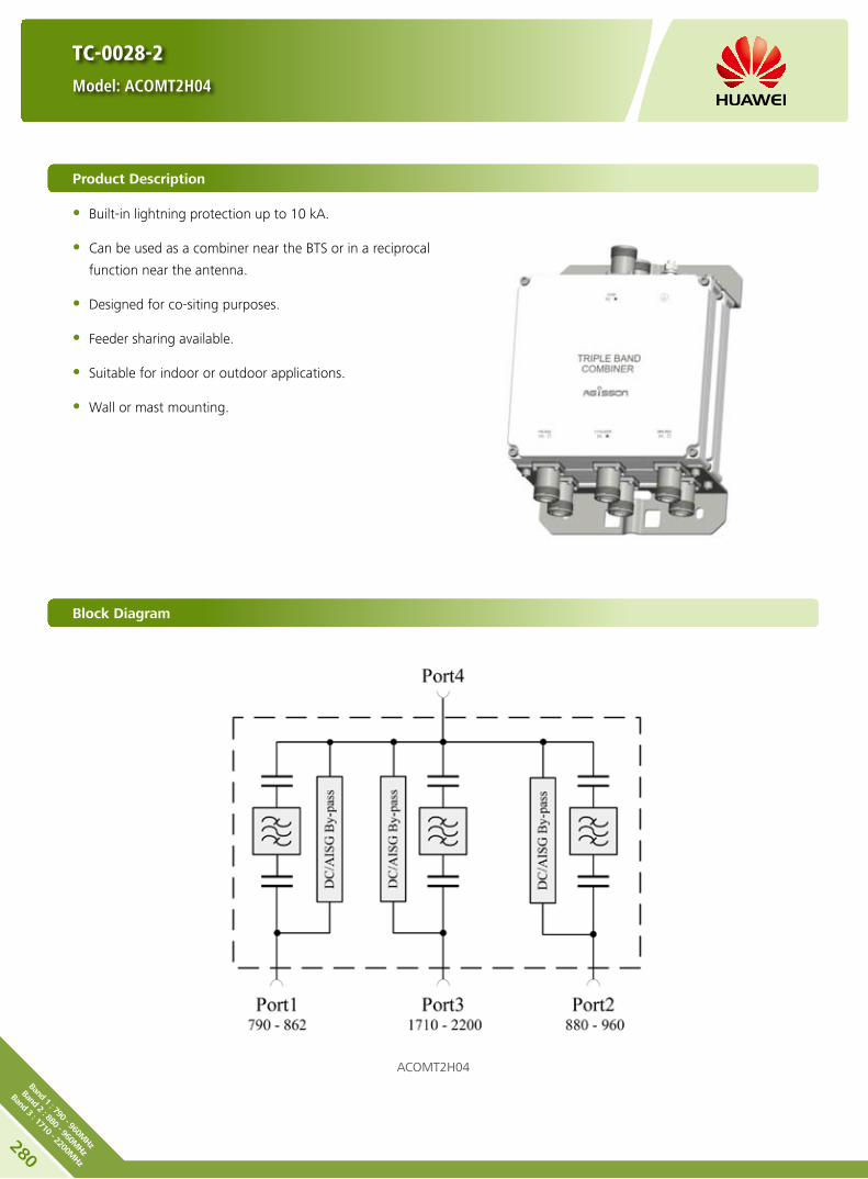
280
Band 1 : 790 - 960MHz
Band 2 : 880 - 960MHz
Band 3 : 1710 - 2200MHz
TC-0028-2
Model: ACOMT2H04
Product Description
Built-in lightning protection up to 10 kA. y
Can be used as a combiner near the BTS or in a reciprocal y
function near the antenna.
Designed for co-siting purposes. y
Feeder sharing available. y
Suitable for indoor or outdoor applications. y
Wall or mast mounting. y
Block Diagram
ACOMT2H04

TC-0028-2
Model: ACOMT2H04
Electrical Properties
Model ACOMT2H04
Pass band (MHz)
Band 1 790 - 862
Band 2 880 - 960
Band 3 1710 - 2200
Insertion loss* (dB)
Port 1 ←→ Port 4 < 0.3 (790 MHz - 862 MHz)
Port 2 ←→ Port 4 < 0.25 (880 MHz - 960 MHz)
Port 3 ←→ Port 4 < 0.15 (1710 MHz - 2200 MHz)
DC/AISG transparency
Port 1 ←→ Port 4 By-pass (max. 2500 mA)
Port 2 ←→ Port 4 By-pass (max. 2500 mA)
Port 3 ←→ Port 4 By-pass (max. 2500 mA)
Isolation (dB)
Port 1 ←→ Port 2 > 50
Port 2 ←→ Port 3 > 70
Port 1 ←→ Port 3 > 70
VSWR < 1.24
Input power (W) Port 1, Port 2, Port3 < 300
Intermodulation products (dBm) < -117 (3rd order; with 2 x 43 dBm)
Environmental Specification
Operating temperature () -40 .. +65
Application scene Indoor // outdoor
IP rating IP67
Lightning protection (kA) 10 (8/20 us)
Mechanical Specification
Connector 7/16 DIN Female (Long neck)
Mounting Wall mounting // Mast mounting
Weight (kg) Double Unit: ≤ 7.5
Mast diameter (mm) Default: 40 - 135
Dimensions (W x H x D) (mm)Double Unit: 220 x 210 x 115
(without connectors, without mounting brackets)
281Ba
nd 1 : 79
0 - 9
60M
Hz
Band
2 : 88
0 - 9
60M
Hz
Band
3 : 17
10 - 22
00M
Hz

TC-0028-2
Model: ACOMT2H04
Unit: mm
Any previous catalogue issues become invalid.
Issue: 2012-10-26
HUAWEI TECHNOLOGIES CO., LTD.
Huawei Industrial BaseBantian Longgang
Shenzhen 518129, P.R. ChinaTel: +86-755-28780808
Email: [email protected]
www.huawei.com
Copyright © Huawei Technologies Co., Ltd. 2013. All rights reserved.
THIS DOCUMENT IS FOR INFORMATION PURPOSE ONLY, AND DOSE NOT CONSTITUTE ANY KIND OF WARRANTIES.
282
Band 1 : 790 - 960MHz
Band 2 : 880 - 960MHz
Band 3 : 1710 - 2200MHz

Product Description
Built-in lightning protection up to 10 kA. y
Can be used as a combiner near the BTS or in a reciprocal y
function near the antenna.
Designed for co-siting purposes and feeder sharing y
Suitable for indoor or outdoor applications. y
Wall or mast mounting. y
Block Diagram
ACOMT2H00 ACOMT2H02
TC-0011-2 Model: ACOMT2H00
TC-0015-2 Model: ACOMT2H02
283Ba
nd 1 : 79
0 - 9
60M
Hz
Band
2 : 17
10 - 18
80M
Hz
Band
3 : 19
20 - 22
00M
Hz

TC-0011-2 Model: ACOMT2H00
TC-0015-2 Model: ACOMT2H02
Electrical Properties
Model ACOMT2H00 ACOMT2H02
Pass band (MHz)
Band 1 790 - 960
Band 2 1710 - 1880
Band 3 1920 - 2200
Insertion loss* (dB)
Port 1 ←→ Port 4 Typ. < 0.15 (790 MHz - 960 MHz)
Port 2 ←→ Port 4 Typ. < 0.25 (1710 MHz - 1880 MHz)
Port 3 ←→ Port 4 Typ. < 0.25 (1920 MHz - 2200 MHz)
DC/AISG transparency
Port 1 ←→ Port 4 Stop Stop
Port 2 ←→ Port 4 Stop By-pass (max. 2500 mA)
Port 3 ←→ Port 4 By-pass (max. 2500 mA) By-pass (max. 2500 mA)
Isolation (dB) > 45
VSWR < 1.28
Input power (W) Port 1, Port 2, Port3 < 300
Intermodulation products (dBm) < -117 (3rd order; with 2 x 43 dBm)
Environmental Specification
Operating temperature () -40 .. +65
Application scene Indoor // Outdoor
IP rating IP67
Lightning protection (kA) 10 (8/20 us)
Mechanical Specification
Combiner dimensions (W x H x D) (mm)Double Unit: 190 x 154 x 105
(without connectors, without mounting brackets)
Packing dimensions (W x H x D) (mm) 365 x 260 x 210
Combiner weight (kg) Double Unit: ≤ 6.3
Packing weight (kg) ≤ 7.3
Mounting Wall mounting // Mast mounting
Mast diameter (mm) Default: 40 - 135
Connector 7/16 DIN Female (Long neck)
284
Band 1 : 790 - 960MHz
Band 2 : 1710 - 1880MHz
Band 3 : 1920 - 2200MHz

TC-0011-2 Model: ACOMT2H00
TC-0015-2 Model: ACOMT2H02
Unit: mm
Any previous catalogue issues become invalid.
Issue: 2012-10-26
HUAWEI TECHNOLOGIES CO., LTD.
Huawei Industrial BaseBantian Longgang
Shenzhen 518129, P.R. ChinaTel: +86-755-28780808
Email: [email protected]
www.huawei.com
Copyright © Huawei Technologies Co., Ltd. 2013. All rights reserved.
THIS DOCUMENT IS FOR INFORMATION PURPOSE ONLY, AND DOSE NOT CONSTITUTE ANY KIND OF WARRANTIES.
285Ba
nd 1 : 79
0 - 9
60M
Hz
Band
2 : 17
10 - 18
80M
Hz
Band
3 : 19
20 - 22
00M
Hz
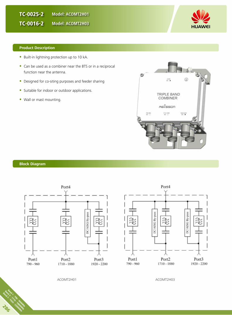
286
Band 1 : 790 - 960MHz
Band 2 : 1710 - 1880MHz
Band 3 : 1920 - 2200MHz
TC-0025-2 Model: ACOMT2H01
TC-0016-2 Model: ACOMT2H03
Product Description
Built-in lightning protection up to 10 kA. y
Can be used as a combiner near the BTS or in a reciprocal y
function near the antenna.
Designed for co-siting purposes and feeder sharing y
Suitable for indoor or outdoor applications. y
Wall or mast mounting. y
Block Diagram
ACOMT2H01 ACOMT2H03

TC-0025-2 Model: ACOMT2H01
TC-0016-2 Model: ACOMT2H03
Electrical Properties
Model ACOMT2H01 ACOMT2H03
Pass band (MHz)
Band 1 790 - 960
Band 2 1710 - 1880
Band 3 1920 - 2200
Insertion loss* (dB)
Port 1 ←→ Port 4 Typ. < 0.15 (790 MHz - 960 MHz)
Port 2 ←→ Port 4 Typ. < 0.25 (1710 MHz - 1880 MHz)
Port 3 ←→ Port 4 Typ. < 0.25 (1920 MHz - 2200 MHz)
DC/AISG transparency
Port 1 ←→ Port 4 Stop Stop
Port 2 ←→ Port 4 Stop By-pass (max. 2500 mA)
Port 3 ←→ Port 4 By-pass (max. 2500 mA) By-pass (max. 2500 mA)
Isolation (dB) > 45
VSWR < 1.28
Input power (W) Port 1, Port 2, Port3 < 300
Intermodulation products (dBm) < -110 (3rd order; with 2 x 43 dBm)
Environmental Specification
Operating temperature () -40 .. +65
Application scene Indoor // Outdoor
IP rating IP67
Lightning protection (kA) 10 (8/20 us)
Mechanical Specification
Combiner dimensions (W x H x D) (mm)Double Unit: 190 x 154 x 105
(without connectors, without mounting brackets)
Packing dimensions (W x H x D) (mm) 365 x 260 x 210
Combiner weight (kg) Double Unit: ≤ 6.3
Packing weight (kg) ≤ 7.3
Mounting Wall mounting // Mast mounting
Mast diameter (mm) Default: 40 - 135
Connector 7/16 DIN Female (Long neck)
287Ba
nd 1 : 79
0 - 9
60M
Hz
Band
2 : 17
10 - 18
80M
Hz
Band
3 : 19
20 - 22
00M
Hz

TC-0025-2 Model: ACOMT2H01
TC-0016-2 Model: ACOMT2H03
Unit: mm
Any previous catalogue issues become invalid.
Issue: 2012-10-26
HUAWEI TECHNOLOGIES CO., LTD.
Huawei Industrial BaseBantian Longgang
Shenzhen 518129, P.R. ChinaTel: +86-755-28780808
Email: [email protected]
www.huawei.com
Copyright © Huawei Technologies Co., Ltd. 2013. All rights reserved.
THIS DOCUMENT IS FOR INFORMATION PURPOSE ONLY, AND DOSE NOT CONSTITUTE ANY KIND OF WARRANTIES.
288
Band 1 : 790 - 960MHz
Band 2 : 1710 - 1880MHz
Band 3 : 1920 - 2200MHz

DC-0041-2
Model: ACOMT2H08
Product Description
Built-in lightning protection up to 10 kA. y
Can be used as a combiner near the BTS or in a reciprocal y
function near the antenna.
Designed for co-siting purposes. y
Feeder sharing available. y
Suitable for indoor or outdoor applications. y
Wall or mast mounting. y
Block Diagram
ACOMT2H08
Preliminary Issue
289Ba
nd 1 : 79
0 - 9
60M
Hz
Band
2 : 17
10 - 18
80M
Hz
Band
3 : 19
20 - 22
00M
Hz

DC-0041-2
Model: ACOMT2H08
Electrical Properties
Model ACOMT2H08
Pass band (MHz)
Band 1 790 - 960
Band 2 1710 - 1880
Band 3 1920 - 2200
Insertion loss* (dB)
Port 1 ←→ Port 4 < 0.15 (790 MHz - 960 MHz)
Port 2 ←→ Port 4 < 0.25 (1710 MHz - 1880 MHz)
Port 3 ←→ Port 4 < 0.25 (1920 MHz - 2200 MHz)
DC/AISG transparency
Port 1 ←→ Port 4 By-pass (max. 2500 mA)
Port 2 ←→ Port 4 By-pass (max. 2500 mA)
Port 3 ←→ Port 4 By-pass (max. 2500 mA)
Isolation (dB) > 45
VSWR < 1.28
Input power (W) Port 1, Port 2, Port3 < 300
Intermodulation products (dBm) < -110 (3rd order; with 2 x 43 dBm)
Environmental Specification
Operating temperature () -40 … +65
Application scene Indoor // Outdoor
IP rating IP67
Lightning protection (kA) 10 (8/20 us)
Mechanical Specification
Combiner dimensions (W x H x D) (mm)Double Unit: 190 x 154 x 105
(without connectors, without mounting brackets)
Packing dimensions (W x H x D) (mm) 365 x 260 x 210
Combiner weight (kg) Double Unit: ≤ 6.3
Packing weight (kg) ≤ 7.3
Mounting Wall mounting // Mast mounting
Mast diameter (mm) Default: 40 - 135
Connector 7/16 DIN Female (Long neck)
Preliminary Issue
290
Band 1 : 790 - 960MHz
Band 2 : 1710 - 1880MHz
Band 3 : 1920 - 2200MHz

DC-0041-2
Model: ACOMT2H08
Unit: mm
Any previous catalogue issues become invalid.
Issue: 2013-01-08
HUAWEI TECHNOLOGIES CO., LTD.
Huawei Industrial BaseBantian Longgang
Shenzhen 518129, P.R. ChinaTel: +86-755-28780808
Email: [email protected]
www.huawei.com
Copyright © Huawei Technologies Co., Ltd. 2013. All rights reserved.
THIS DOCUMENT IS FOR INFORMATION PURPOSE ONLY, AND DOSE NOT CONSTITUTE ANY KIND OF WARRANTIES.
Preliminary Issue
291Ba
nd 1 : 79
0 - 9
60M
Hz
Band
2 : 17
10 - 18
80M
Hz
Band
3 : 19
20 - 22
00M
Hz

292
Band 1 : 790 - 1880MHz
Band 2 : 1920 - 2200MHz
Band 3 : 2490 - 2700MHz
Product Description
Built-in lightning protection up to 10 kA. y
Can be used as a combiner near the BTS or in a reciprocal y
function near the antenna.
Designed for co-siting purposes and feeder sharing y
Suitable for indoor or outdoor applications. y
Wall or mast mounting. y
Block Diagram
ACOMT2M00
TC-0009-2
Model: ACOMT2M00
Preliminary Issue

TC-0009-2
Model: ACOMT2M00
Electrical Properties
Model ACOMT2M00
Pass band (MHz)
Band 1 790 - 1880
Band 2 1920 - 2200
Band 3 2490 - 2700
Insertion loss* (dB)
Port 1 ←→ Port 4 Typ. < 0.15 (790 MHz - 960 MHz)
Typ. < 0.25 (1710 MHz - 1880 MHz)
Port 2 ←→ Port 4 Typ. < 0.25 (1920 MHz - 2200 MHz)
Port 3 ←→ Port 4 Typ. < 0.2 (2490 MHz - 2700 MHz)
DC/AISG transparency
Port 1 ←→ Port 4 Stop
Port 2 ←→ Port 4 By-pass (max. 2500 mA)
Port 3 ←→ Port 4 Stop
Isolation (dB) > 45
VSWR < 1.28
Input power (W) Port 1, Port 2, Port3 < 300
Intermodulation products (dBm) < -110 (3rd order; with 2 x 43 dBm)
Environmental Specification
Operating temperature () -40 .. +65
Application scene Indoor // Outdoor
IP rating IP67
Lightning protection (kA) 10 (8/20 us)
Mechanical Specification
Connector 7/16 DIN Female (long neck)
Mounting Wall mounting // Mast mounting
Weight (kg) Double Unit: ≤ 7
Mast diameter (mm) 40 - 135
Dimensions (W x H x D) (mm) Double Unit: 215 x 200 x 105
(without connectors, without mounting brackets)
Preliminary Issue
293Ba
nd 1 : 79
0 - 1
880M
Hz
Band
2 : 19
20 - 22
00M
Hz
Band
3 : 24
90 - 27
00M
Hz
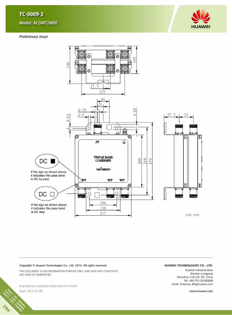
TC-0009-2
Model: ACOMT2M00
Unit: mm
Any previous catalogue issues become invalid.
Issue: 2013-01-08
HUAWEI TECHNOLOGIES CO., LTD.
Huawei Industrial BaseBantian Longgang
Shenzhen 518129, P.R. ChinaTel: +86-755-28780808
Email: [email protected]
www.huawei.com
Copyright © Huawei Technologies Co., Ltd. 2013. All rights reserved.
THIS DOCUMENT IS FOR INFORMATION PURPOSE ONLY, AND DOSE NOT CONSTITUTE ANY KIND OF WARRANTIES.
Preliminary Issue
294
Band 1 : 790 - 1880MHz
Band 2 : 1920 - 2200MHz
Band 3 : 2490 - 2700MHz

TC-0043-2
Model: ACOMT2M09
Product Description
Built-in lightning protection up to 10 kA. y
Can be used as a combiner near the BTS or in a reciprocal y
function near the antenna.
Designed for co-siting purposes. y
Feeder sharing available. y
Suitable for indoor or outdoor applications. y
Wall or mast mounting. y
Block Diagram
ACOMT2M09
Preliminary Issue
295Ba
nd 1 : 69
8 - 9
60M
Hz
Band
2 : 17
10 - 22
00M
Hz
Band
3 : 24
90 - 27
00M
Hz

TC-0043-2
Model: ACOMT2M09
Electrical Properties
Model ACOMT2M09
Pass band (MHz)
Band 1 698 - 960
Band 2 1710 - 2200
Band 3 2490 - 2700
Insertion loss* (dB)
Port 1 ←→ Port 4 < 0.15 (698 MHz - 960 MHz)
Port 2 ←→ Port 4 < 0.25 (1710 MHz - 2200 MHz)
Port 3 ←→ Port 4 < 0.2 (2490 MHz - 2700 MHz)
DC/AISG transparency
Port 1 ←→ Port 4 By-pass (max. 2500 mA)
Port 2 ←→ Port 4 By-pass (max. 2500 mA)
Port 3 ←→ Port 4 By-pass (max. 2500 mA)
Isolation (dB) > 45
VSWR < 1.28
Input power (W) Port 1, Port 2, Port3 < 300
Intermodulation products (dBm) < -110 (3rd order; with 2 x 43 dBm)
Environmental Specification
Operating temperature () -40 … +65
Application scene Indoor // Outdoor
IP rating IP67
Lightning protection (kA) 10 (8/20 us)
Mechanical Specification
Combiner dimensions (W x H x D) (mm)Double Unit: 215 x 200 x 105
(without connectors, without mounting brackets)
Packing dimensions (W x H x D) (mm) 400 x 340 x 240
Combiner weight (kg) Double Unit: ≤ 7.3
Packing weight (kg) ≤ 8.7
Mounting Wall mounting // Mast mounting
Mast diameter (mm) Default: 40 - 135
Connector 7/16 DIN Female (Long neck)
Preliminary Issue
296
Band 1 : 698 - 960MHz
Band 2 : 1710 - 2200MHz
Band 3 : 2490 - 2700MHz

TC-0043-2
Model: ACOMT2M09
Unit: mm
Any previous catalogue issues become invalid.
Issue: 2013-01-08
HUAWEI TECHNOLOGIES CO., LTD.
Huawei Industrial BaseBantian Longgang
Shenzhen 518129, P.R. ChinaTel: +86-755-28780808
Email: [email protected]
www.huawei.com
Copyright © Huawei Technologies Co., Ltd. 2013. All rights reserved.
THIS DOCUMENT IS FOR INFORMATION PURPOSE ONLY, AND DOSE NOT CONSTITUTE ANY KIND OF WARRANTIES.
Preliminary Issue
297Ba
nd 1 : 69
8 - 9
60M
Hz
Band
2 : 17
10 - 22
00M
Hz
Band
3 : 24
90 - 27
00M
Hz

QC-0007-2
Model: ACOMQ2M00
Product Description
Built-in lightning protection up to 10 kA. y
Can be used as a combiner near the BTS or in a reciprocal y
function near the antenna.
Designed for co-siting purposes and feeder sharing y
Suitable for indoor or outdoor applications. y
Wall or mast mounting. y
Block Diagram
ACOMQ2M00
Preliminary Issue
298
Band 1 : 790 - 960MHz
Band 2 : 1710 -1880MHz
Band 3 : 1920 - 2200MHz
Band 4 : 2490 - 2700MHz

QC-0007-2
Model: ACOMQ2M00
Electrical Properties
Model ACOMQ2M00
Pass band (MHz)
Band 1 790 - 960
Band 2 1710 - 1880
Band 3 1920 - 2200
Band 4 2490 - 2700
Insertion loss* (dB)
Port 1 ←→ Port 5 Typ. < 0.15 (790 MHz - 960 MHz)
Port 2 ←→ Port 5 Typ. < 0.25 (1710 MHz - 1880 MHz)
Port 3 ←→ Port 5 Typ. < 0.25 (1920 MHz - 2200 MHz)
Port 4 ←→ Port 5 Typ. < 0.2 (2490 MHz - 2700 MHz)
DC/AISG transparency
Port 1 ←→ Port 5 Stop
Port 2 ←→ Port 5 Stop
Port 3 ←→ Port 5 By- pass (max. 2500 mA)
Port 4 ←→ Port 5 stop
Isolation (dB) > 45
VSWR < 1.28
Input power (W) Port 1, Port 2 Port 3, Port 4
< 300
Intermodulation products (dBm) < -110 (3rd order; with 2 x 43 dBm)
Environmental Specification
Operating temperature () -40 .. +65
Application scene Indoor // Outdoor
IP rating IP67
Lightning protection (kA) 10 (8/20 us)
Mechanical Specification
Connector 7/16 DIN Female (long neck)
Mounting Wall mounting // Mast mounting
Weight (kg) Double Unit: ≤ 7.5
Mast diameter (mm) 40 - 135
Dimensions (W x H x D) (mm) Double Unit: 215 x 200 x 105
(without connectors, without mounting brackets)
Preliminary Issue
299
Band
1 : 79
0 - 9
60M
Hz
Band
2 : 17
10 -1
880M
Hz
Band
3 : 19
20 - 22
00M
Hz
Band
4 : 24
90 - 27
00M
Hz

QC-0007-2
Model: ACOMQ2M00
Unit: mm
Any previous catalogue issues become invalid.
Issue: 2013-01-08
HUAWEI TECHNOLOGIES CO., LTD.
Huawei Industrial BaseBantian Longgang
Shenzhen 518129, P.R. ChinaTel: +86-755-28780808
Email: [email protected]
www.huawei.com
Copyright © Huawei Technologies Co., Ltd. 2013. All rights reserved.
THIS DOCUMENT IS FOR INFORMATION PURPOSE ONLY, AND DOSE NOT CONSTITUTE ANY KIND OF WARRANTIES.
Preliminary Issue
300
Band 1 : 790 - 960MHz
Band 2 : 1710 -1880MHz
Band 3 : 1920 - 2200MHz
Band 4 : 2490 - 2700MHz

QC-0032-2
Model: ACOMQ2H00
Product Description
Built-in lightning protection up to 10 kA. y
Can be used as a combiner near the BTS or in a reciprocal y
function near the antenna.
Designed for co-siting purposes. y
Feeder sharing available. y
Suitable for indoor or outdoor applications. y
Wall or mast mounting. y
Block Diagram
ACOMQ2H00
Preliminary Issue
301
Band
1 : 79
0 - 9
60M
Hz
Band
2 : 17
10 -1
880M
Hz
Band
3 : 19
20 - 22
00M
Hz
Band
4 : 24
90 - 27
00M
Hz

QC-0032-2
Model: ACOMQ2H00
Electrical Properties
Model ACOMQ2H00
Pass band (MHz)
Band 1 790 - 960
Band 2 1710 - 1880
Band 3 1920 - 2200
Band 4 2490 - 2700
Insertion loss* (dB)
Port 1 ←→ Port 5 < 0.15 (790 MHz - 960 MHz)
Port 2 ←→ Port 5 < 0.25 (1710 MHz - 1880 MHz)
Port 3 ←→ Port 5 < 0.25 (1920 MHz - 2200 MHz)
Port 4 ←→ Port 5 < 0.2 (2490 MHz - 2700 MHz)
DC/AISG transparency
Port 1 ←→ Port 5 By- pass (max. 2500 mA)
Port 2 ←→ Port 5 By- pass (max. 2500 mA)
Port 3 ←→ Port 5 By- pass (max. 2500 mA)
Port 4 ←→ Port 5 By- pass (max. 2500 mA)
Isolation (dB) > 45
VSWR < 1.28
Input power (W) Port 1, Port 2 Port 3, Port 4
< 300
Intermodulation products (dBm) < -110 (3rd order; with 2 x 43 dBm)
Environmental Specification
Operating temperature () -40 … +65
Application scene Indoor // Outdoor
IP rating IP67
Lightning protection (kA) 10 (8/20 us)
Mechanical Specification
Combiner dimensions (W x H x D) (mm)Double Unit: 215 x 200 x 105
(without connectors, without mounting brackets)
Packing dimensions (W x H x D) (mm) 400 x 340 x 240
Combiner weight (kg) Double Unit: ≤ 7.5
Packing weight (kg) ≤ 8.9
Mounting Wall mounting // Mast mounting
Mast diameter (mm) Default: 40 - 135
Connector 7/16 DIN Female (Long neck)
Preliminary Issue
302
Band 1 : 790 - 960MHz
Band 2 : 1710 -1880MHz
Band 3 : 1920 - 2200MHz
Band 4 : 2490 - 2700MHz

QC-0032-2
Model: ACOMQ2H00
Unit: mm
Any previous catalogue issues become invalid.
Issue: 2013-01-08
HUAWEI TECHNOLOGIES CO., LTD.
Huawei Industrial BaseBantian Longgang
Shenzhen 518129, P.R. ChinaTel: +86-755-28780808
Email: [email protected]
www.huawei.com
Copyright © Huawei Technologies Co., Ltd. 2013. All rights reserved.
THIS DOCUMENT IS FOR INFORMATION PURPOSE ONLY, AND DOSE NOT CONSTITUTE ANY KIND OF WARRANTIES.
Preliminary Issue
303
Band
1 : 79
0 - 9
60M
Hz
Band
2 : 17
10 -1
880M
Hz
Band
3 : 19
20 - 22
00M
Hz
Band
4 : 24
90 - 27
00M
Hz
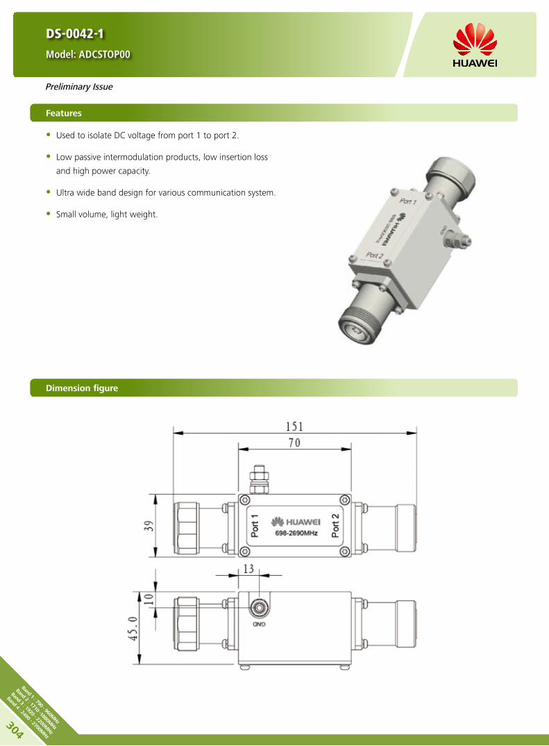
DS-0042-1
Model: ADCSTOP00
Features
Used to isolate DC voltage from port 1 to port 2. y
Low passive intermodulation products, low insertion loss y
and high power capacity.
Ultra wide band design for various communication system. y
Small volume, light weight. y
Dimension figure
ACOMQ2M00
Preliminary Issue
304
Band 1 : 790 - 960MHz
Band 2 : 1710 -1880MHz
Band 3 : 1920 - 2200MHz
Band 4 : 2490 - 2700MHz

DS-0042-1
Model: ADCSTOP00
Electrical Properties
Model ADCSTOP00
Frequency range (MHz) 698 - 2690
Insertion loss (dB)Port 1 ←→ Port 2
≤ 0.1 (698 - 960 MHz // 1710 - 2690 MHz)≤ 0.15 (960 - 1710 MHz)
Isolation for DC signal (dB)
Port 1 ←→ Port 2 ≥ 70
VSWR Port 1 and Port 2≤ 1.15 (698 - 960 MHz // 1710 - 2690 MHz)
≤ 1.2 (960 - 1710 MHz)
Input power (W) Port 1 and Port 2 Avg. ≥ 500 (698 - 2690 MHz)
RF Impedance (Ω) 50
Intermodulation products (dBc) < -160 (2 x 43 dBm carrier)
Environmental Specification
Operating temperature () -40 … +70
Application scene Indoor // Outdoor
IP rating IP66
Lightning protection (kA) 3 (10/350 us)
Mechanical Specification
BT Dimensions (W x H x D) (mm) 39 x 151 x 45
Packing dimensions (W x H x D) (mm) 78 x 185 x 58
BT net Weight (kg) < 0.56
Packing weight (kg) < 0.60
ConnectorsPort 1 7/16 DIN Male
Port 2 7/16 DIN Female
Preliminary Issue
Any previous catalogue issues become invalid.
Issue: 2013-01-08
HUAWEI TECHNOLOGIES CO., LTD.
Huawei Industrial BaseBantian Longgang
Shenzhen 518129, P.R. ChinaTel: +86-755-28780808
Email: [email protected]
www.huawei.com
Copyright © Huawei Technologies Co., Ltd. 2013. All rights reserved.
THIS DOCUMENT IS FOR INFORMATION PURPOSE ONLY, AND DOSE NOT CONSTITUTE ANY KIND OF WARRANTIES.
305
DC-ST
OP
Band
: 69
8 - 2
700M
Hz

Accessories for RET SystemsC

Antenna and RCU configuration list
307
RCU
RCU
AISG 1.1 ARCU01104
AISG 2.0 ARCU02001
Antenna Model Single Band A90451704 A19452101 A19451703 A25451803 A25451804
RCU
AISG 1.1 ARCU01109
AISG 2.0 ARCU02004
Antenna Model
Single Band
A70451501 A70451600 A70451700 A70451500 A79451500v01
A79451600v01 A79451700v01 A19451505 A19451811 A194518R0
A26451500 A19451902 A26451800v01 A264518R0 A26451900v01
A25451805 A264518S0
Dual-band
ADU4515R0 ADU4516R0 ADU4517R0 ADU451503 ADU451602v01
ADU4518R3 ADU451807v01 ADU4518R0 ADU4517C0 ADU4518C1
ADU4518C0 ADU451820 ADU451821 ADU451716 ADU451604
ADU451611 ADU451712 ADU451819 ADU4518R1 ADU451902
ADU4518R5 ADU451507 ADU451816v01 ADU4518R6 ADU451901v01
Triple-band
ATR451500 ATR451602v01 ATR4516R0 ATR451704v01 ATR451612
ATR451713 ATR4517R0 ATR4518R4 ATR4518R7 ATR451709
ATR451606 ATR451607 ATR4518R9 ATR4518R3 ATR451714
Quad-band AQU4518R0 AQU4518R1
Penta-band APE4517R2

308
RCU
RCU Model: ARCU01104 (AISG 1.1) ARCU02001 (AISG 2.0)
RCU (Remote Control Unit) drives the phase shifter in antenna through mechanical interface to change the electrical
downtilt. RCU is suitable for daisy chain solution.
HINT: Before the installation, check whether the RCU and base station support the same AISG protocol. If not, contact
the technical support personnel of Huawei.
Appearance Bottom view of RCU Male Female
Daisy chain in: Male
Daisy chain out: Female
Input voltage range (V) DC 10 - 30
Current (mA) < 600 (motor activated)
< 50 (stand by)
Adjustment time (full range) (min) < 2
Calibration time (min) < 4
Connectors 2 x 8 pin connector according to IEC 60130-9 Daisy chain in: Male // Daisy chain out: Female
Pin assignment according AISG 1 2 3 4 5 6 7 8
DC n/c RS-485B n/c RS-485A DC in/out DC return n/c
Housing material Profile: Aluminium coated / Cover: Aluminium coated
Color Grey
Weight (g) 600
Operating temperature range () -40 .. +65
Protection class IP24
Dimensions (L x W x H) (mm) 200 x 56 x 47
Packing size (L x W x H) (mm) 268 x 105 x 95
Drainage
Hole
Drainage
Hole
Any previous catalogue issues become invalid.
Issue: 2012-10-26
HUAWEI TECHNOLOGIES CO., LTD.
Huawei Industrial BaseBantian Longgang
Shenzhen 518129, P.R. ChinaTel: +86-755-28780808
Email: [email protected]
www.huawei.com
Copyright © Huawei Technologies Co., Ltd. 2013. All rights reserved.
THIS DOCUMENT IS FOR INFORMATION PURPOSE ONLY, AND DOSE NOT CONSTITUTE ANY KIND OF WARRANTIES.

309
RCU
RCU (Remote Control Unit) drives the phase shifter in antenna through mechanical interface to change the electrical
downtilt. RCU is suitable for daisy chain solution.
Standards: EN 60950-1 (Safety)
EN 55022 (Emission)
EN 55024 (Immunity)
ETSI EN300386 (1.4.1)
FCC part15
Certification: CE、FCC、RoHS、WEEE
Input voltage range (V) DC 10 - 30
Current (mA) < 10 (motor activated)
< 0.5 (stand by)
Adjustment time (full range) (min) < 1.5 (typically, depending on antenna type)
Calibration time (min) < 3 (typically, depending on antenna type)
Connectors 2 x 8 pin connector according to IEC 60130-9 Daisy chain in: Male / Daisy chain out: Female
Pin assignment according AISG 1 2 3 4 5 6 7 8
DC n/c RS-485B n/c RS-485A DC in/out DC return n/c
Housing material Profile: Aluminium coated / Cover: Aluminium coated
Color RAL 7035
Weight (g) 600
Operating temperature range () -40 .. +65
Protection class IP24
Lightning protection (kA) AISG interface (each pin)
3 (10/350 μs) 10 (8/20 μs)
Dimensions (L x W x H) (mm) 180 x 65 x 54
Packing size (L x W x H) (mm) 268 x 105 x 95
Appearance Bottom view of RCU Male Female
Daisy chain in: Male
Daisy chain out: Female
RCU Model: ARCU01109 (AISG 1.1) ARCU02004 (AISG 2.0)
HINT: Before the installation, check whether the RCU
and base station support the same AISG protocol. If not,
contact the technical support personnel of Huawei.
Drainage
Hole
Any previous catalogue issues become invalid.
Issue: 2012-10-26
HUAWEI TECHNOLOGIES CO., LTD.
Huawei Industrial BaseBantian Longgang
Shenzhen 518129, P.R. ChinaTel: +86-755-28780808
Email: [email protected]
www.huawei.com
Copyright © Huawei Technologies Co., Ltd. 2013. All rights reserved.
THIS DOCUMENT IS FOR INFORMATION PURPOSE ONLY, AND DOSE NOT CONSTITUTE ANY KIND OF WARRANTIES.

310
BT
BT = Bias Tee
BTS = Base Transceiver Station
OOK = On Off Keying
BT-690-2700-001
Model: ABT000001
Features
Used to feed DC voltage and OOK control signals into the feeder cable. y
Low passive intermodulation products, low insertion loss and high power capacity. y
Ultra wide band design for various communication system. y
Small volume, light weight. y
Support AISG 1.1 and AISG 2.0 protocol. y
Block Diagram
RF Block
DC Block
Port 2 (ANT)
DC/OOK
Port 1 (BTS)

311
BT
BT-690-2700-001
Model: ABT000001
Electrical Properties
Frequency range (MHz) 690 - 2700
Insertion loss (dB) Port 1 ←→ Port 2 ≤ 0.1 (690 - 960 MHz / 1710 - 2690 MHz)
≤ 0.15 (960 - 1710 MHz)
Isolation for DC signal (dB)Port 1 ←→ Port 2
≥ 70Port 1 ←→ Port DC/OOK
VSWR Port 1 and Port 2≤ 1.15 (690 - 960 MHz / 1710 - 2690 MHz)
≤ 1.2 (960 - 1710 MHz)
Input power (W) Port 1 and Port 2 Avg. ≥ 500 (690 - 960 MHz)
Avg. ≥ 250 (1710 - 2690 MHz)
Input current (mA) Port DC/OOK ←→ Port 2 ≤ 2300
DC voltage reduction (V) Port DC/OOK ←→ Port 2 ≤ 1 (when the current is 2300 mA)
DC supply voltage (V) 0 .. +30
RF Impedance (Ω) 50
Intermodulation products (dBc) < -160 (2 x 43 dBm carrier)
Environmental Specification
Operating temperature () -40 .. +70
Application scene Indoor or outdoor
IP rating IP66
Lightning protection (kA) 3 (10/350 us)
Mechanical Specification
BT Dimensions (W x H x D) (mm) 48.5 x 151 x 45 (with connectors)
Packing dimensions (W x H x D) (mm) 78 x 185 x 58
BT net Weight (kg) < 0.56
Packing weight (kg) < 0.60
Connectors
Port 1 (BTS) 7/16 DIN Male
Port 2 (Antenna) 7/16 DIN Female
Port DC/OOK SMA Female

312
BT
Unit: mm
BT-690-2700-001
Model: ABT000001
Any previous catalogue issues become invalid.
Issue: 2012-10-26
HUAWEI TECHNOLOGIES CO., LTD.
Huawei Industrial BaseBantian Longgang
Shenzhen 518129, P.R. ChinaTel: +86-755-28780808
Email: [email protected]
www.huawei.com
Copyright © Huawei Technologies Co., Ltd. 2013. All rights reserved.
THIS DOCUMENT IS FOR INFORMATION PURPOSE ONLY, AND DOSE NOT CONSTITUTE ANY KIND OF WARRANTIES.

313
SBT
SBT = Smart Bias Tee
RCU = Remote Control Unit for remote electrical
control of antenna tilt
BTS = Base Transceiver Station
AISG= Antenna Interface Standards Group
Features
Block Diagram
SBT-690-2700-001 Model: ASBT00001
SBT-690-2700-002 Model: ASBT00002
ASBT00001 ASBT00002
Convert signals between OOK and RS485. y
Low passive intermodulation products, low y
insertion loss and high power capacity.
Ultra wide band design for various y
communication system.
Small volume, light weight. y
Support AISG 1.1 and AISG 2.0 protocol. y

314
SBT
Model ASBT00001 ASBT00002
Port 1 (Connector type) Antenna (7 - 16 DIN Male) BTS (7 - 16 DIN Male)
Port 2 (Connector type) Feeder (7 - 16 DIN Female) Feeder (7 - 16 DIN Female)
Port AISG AISG (8-pin Connecter Female) AISG (8-pin Connecter Male)
SBT-690-2700-001 Model: ASBT00001
SBT-690-2700-002 Model: ASBT00002
Electrical Properties
Frequency range (MHz) 690 - 2700
Insertion loss (dB) Port 1 ←→ Port 2 ≤ 0.1 (690 - 960 MHz / 1710 - 2690 MHz)
≤ 0.15 (960 - 1710 MHz)
Isolation for DC signal (dB)Port 1 ←→ Port 2
≥ 70Port 1 ←→ Port AISG
VSWR Port 1 and Port 2≤ 1.15 (690 - 960 MHz / 1710 - 2690 MHz)
≤ 1.2 (960 - 1710 MHz)
Input power (W)Port 1 and Port 2Port AISG
Avg. ≥ 500 (690 - 960 MHz) / Avg. ≥ 250 (1710 - 2690 MHz)< 2.5 A (+8 … +30 V DC)
DC supply voltage (V) +8 .. +30
RF impedance (Ω) 50
Intermodulation products (dBc) < -160 (3rd order, 2 x 43 dBm)
Power consumption (W) Typ. 0.6
Modem carrier frequency (MHz) 2.176
Environmental Specification
Operating temperature () -40 .. +70
Application scene Indoor or outdoor
IP rating IP67
Lightning protection (kA) 3 (10/350 us)
Mechanical Specification
BT Dimensions (W x H x D) (mm) 75 x 160 x 45 (with connectors)
Packing dimensions (W x H x D) (mm) 78 x 185 x 58
SBT net Weight (kg) < 0.75
Packing weight (kg) < 0.80

315
SBT
SBT-690-2700-001 Model: ASBT00001
SBT-690-2700-002 Model: ASBT00002
ASBT00001
ASBT00002
Unit: mm
Unit: mm
HINT
Extraordinary operating conditions, such as heavy icing or storm wind, may result in the breakage of a SBT. These facts must be considered during the site planning process.
The installation team must be properly qualified and also be familiar with the relevant national safety regulations.
Any previous catalogue issues become invalid.
Issue: 2012-10-26
HUAWEI TECHNOLOGIES CO., LTD.
Huawei Industrial BaseBantian Longgang
Shenzhen 518129, P.R. ChinaTel: +86-755-28780808
Email: [email protected]
www.huawei.com
Copyright © Huawei Technologies Co., Ltd. 2013. All rights reserved.
THIS DOCUMENT IS FOR INFORMATION PURPOSE ONLY, AND DOSE NOT CONSTITUTE ANY KIND OF WARRANTIES.

AISG Connecting Cables
For Remote Electrical Tilt (RET) System
Any previous catalogue issues become invalid.
Issue: 2013-01-08
HUAWEI TECHNOLOGIES CO., LTD.
Huawei Industrial BaseBantian Longgang
Shenzhen 518129, P.R. ChinaTel: +86-755-28780808
Email: [email protected]
www.huawei.com
Copyright © Huawei Technologies Co., Ltd. 2013. All rights reserved.
THIS DOCUMENT IS FOR INFORMATION PURPOSE ONLY, AND DOSE NOT CONSTITUTE ANY KIND OF WARRANTIES.
Pin Number Signal Female Male
1 +12 V DC Nominal
2 N/C
3 RS485 B
4 N/C
5 RS485 A
6 10 V - 30 V DC
7 DC Return
8 N/C
Technical Specification
Connectors2 x 8 pin connector according to IEC 60130-9
Female / Male
Cable 2 x 0.25 mm2 + 4 x 0.75 mm2 cable according to UL2464
Rate current 4 A
Protection Class IP67 (Coupled)
Temperature Range -40 ~ 80
Color Black
Single Bend radius 60 mm Min.
Multiple Bend radius 120 mm Min.
Application scene Indoor // Outdoor
Cable series
Length BOM Code
0.5 m 04045920
2 m 04045921
5 m 04050228
10 m 04050184
15 m 04045922
30 m 04050230
50 m 04050231
60 m 04050182
70 m 04050232
316
AISG

AISG Connecting Cables
For RRU RET_Port
Any previous catalogue issues become invalid.
Issue: 2013-01-08
HUAWEI TECHNOLOGIES CO., LTD.
Huawei Industrial BaseBantian Longgang
Shenzhen 518129, P.R. ChinaTel: +86-755-28780808
Email: [email protected]
www.huawei.com
Copyright © Huawei Technologies Co., Ltd. 2013. All rights reserved.
THIS DOCUMENT IS FOR INFORMATION PURPOSE ONLY, AND DOSE NOT CONSTITUTE ANY KIND OF WARRANTIES.
317
AISG
Pin NumberSignal
Female MaleFemale Male
1 +12 V DC nominal +12 V DC nominal
2 N/C N/C
3 RS485 B RS485 B
4 RS485 GND RS485 GND
5 RS485 A RS485 A
6 10 V - 30 V DC N/C
7 DC Return N/C
8 N/C N/C
9 / DC Return
Technical Specification
Connector 18 pin connector according to IEC 60130-9
Female
Connector 29 pin DB9 connector
Male
Cable 4 Pair x 24 AWG
Rate current 4 A
Protection Class IP67 (Coupled)
Temperature Range 40 ~ 80
Color Black
Single Bend radius 60 mm Min.
Multiple Bend radius 120 mm Min.
Application scene Indoor // Outdoor
Cable series
Length BOM Code
3 m 04070193
5 m 04070097

PCU = Portable Control Unit
RET = Remote Electrical Tilt
RCU = Remote Control Unit
Compliance to standards: 1. Compliant with AISG 1.1 and AISG 2.0 / 3GPP
2. EMC: Emission: Conducted emission (EN 55022, 150 kHz - 30 MHz Class B)
Immunity: Conducted susceptibility (IEC 61000-4-6, 150 kHz - 30 MHz)
PCU
Model: APCU00001
PCU is a portable control unit for RCU of RET antennas. It supports AISG 1.1
and AISG 2.0 / 3GPP protocol. It is portable, lightweight and easy to use for site
installation and maintenance personnel. It can be used as an adapter for USB/
RS485 to connect with PC, PC software via PCU remote control RCU.
Specifications
Connectors to RCU 1 x 8-pin female conforming to IEC 60130-9
Input voltageAC/DC adapter 20 V DC, 1.5 A
Rechargeable battery 16 V DC, 1.5 A
Output voltage to RCU8-pin female: pin1 & pin6: 20 V DC, 1.5 A with external AC/DC adapter
8-pin female: pin1 & pin6: 16 V DC, 1.5 A with inner rechargeable battery
Rechargeable battery Li-polymer (16 V, 2000 mAh), > 300 cycles
External power supplyInput: 100 - 240 V AC, 0.55 A, 50 Hz - 60 Hz
Output: 20 V DC, 1.5 A
LCD128 x 64 dot-matrix LCD, yellow-green backlight, 4 x 8 Chinese characters / 4 x 16
characters
LED
USB Indicating the status of USB connection
RUN Indicating the status of USB/RS485 communication
Power Indicating the status of power supply
Protocol to RCU AISG 1.1 and AISG 2.0 / 3GPP
Interface to PC USB 2.0
Max. number of RCU supported 6 pcs, depending on system configuration and length of control cable
Max. length of control cable 50 m / 6 RCUs (in daisy chain configuration)
Temperature range () -10 .. +55
PCU dimensions (H x W x D) (mm) 168 x 90 x 44
Packing dimensions (H x W x D) (mm) 340 x 275 x 75
PCU net weight (kg) 0.45 (with inner rechargeable battery, without external power adapter)
Packing weight (kg) 1.30
318
PCU

Any previous catalogue issues become invalid.
Issue: 2012-10-26
HUAWEI TECHNOLOGIES CO., LTD.
Huawei Industrial BaseBantian Longgang
Shenzhen 518129, P.R. ChinaTel: +86-755-28780808
Email: [email protected]
www.huawei.com
Copyright © Huawei Technologies Co., Ltd. 2013. All rights reserved.
THIS DOCUMENT IS FOR INFORMATION PURPOSE ONLY, AND DOSE NOT CONSTITUTE ANY KIND OF WARRANTIES.
PCU is used as a RCU controller
PCU is used as a USB/RS485 adapter
(1) RET Antenna
(2) RCU
(3) RF Feeder Cable
(4) AISG Cable
(5) Site
(6) PCU
(1) RET Antenna
(2) RCU
(3) RF Feeder Cable
(4) AISG Cable
(5) Site
(6) PCU
(7) USB Cable
(8) PC
PCU
Model: APCU00001
319
PCU

Mounting InstructionsD

1 Assemble the bracket
HINT
1. Only qualified personnel are allowed to install the antenna. 2. Appearance of the actual antenna may differ from the pictures.
Installation Tools Bracket Subassembly
13 mm combination wrench (2 PCS)
Inclinometer
(1 PCS)M10
(4 PCS)(2 PCS)(1 PCS)16 mm combination wrench
(2 PCS)
2 Install the bracket
MET Antenna with H-Brackets Installation Guide (A)
Part Number: 31043740 Issue: 03
321M
ET In
stallatio
n
Guide
Up bracket
Follow the directions shown
in the picture to install
brackets.
Down bracket
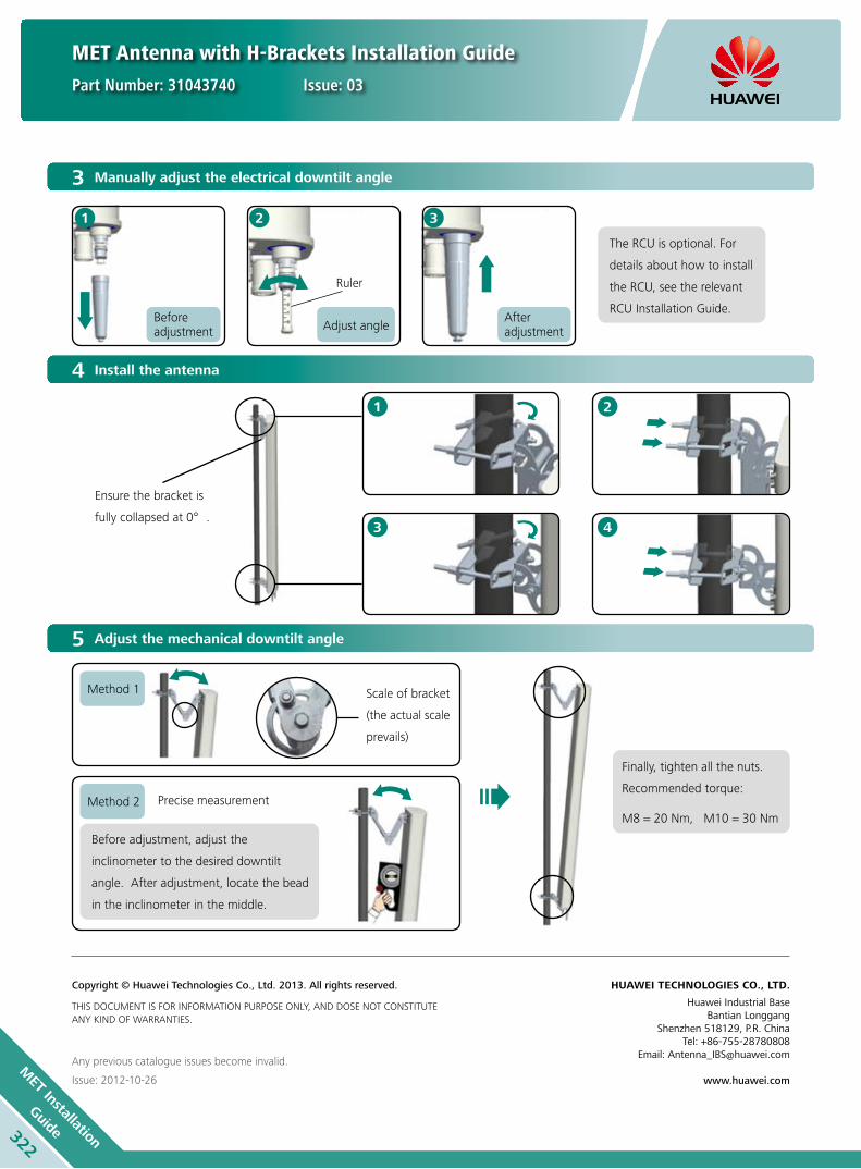
MET Antenna with H-Brackets Installation Guide
Part Number: 31043740 Issue: 03
322
MET Installation
Guide
3 Manually adjust the electrical downtilt angle
After adjustment
Ruler
Before adjustment Adjust angle
The RCU is optional. For
details about how to install
the RCU, see the relevant
RCU Installation Guide.
5 Adjust the mechanical downtilt angle
4 Install the antenna
Any previous catalogue issues become invalid.
Issue: 2012-10-26
HUAWEI TECHNOLOGIES CO., LTD.
Huawei Industrial BaseBantian Longgang
Shenzhen 518129, P.R. ChinaTel: +86-755-28780808
Email: [email protected]
www.huawei.com
Copyright © Huawei Technologies Co., Ltd. 2013. All rights reserved.
THIS DOCUMENT IS FOR INFORMATION PURPOSE ONLY, AND DOSE NOT CONSTITUTE ANY KIND OF WARRANTIES.
1 2 3
2
4
1
3
Ensure the bracket is
fully collapsed at 0°.
Scale of bracket
(the actual scale
prevails)
Precise measurement
Method 1
Method 2
Finally, tighten all the nuts.
Recommended torque:
M8 = 20 Nm, M10 = 30 Nm
Before adjustment, adjust the
inclinometer to the desired downtilt
angle. After adjustment, locate the bead
in the inclinometer in the middle.
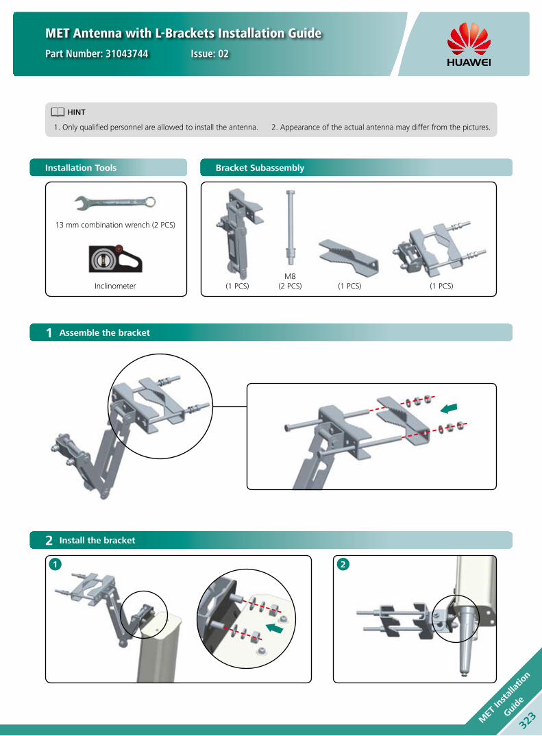
MET Antenna with L-Brackets Installation Guide
Part Number: 31043744 Issue: 02
HINT
1. Only qualified personnel are allowed to install the antenna. 2. Appearance of the actual antenna may differ from the pictures.
323M
ET In
stallatio
n
Guide
Installation Tools Bracket Subassembly
13 mm combination wrench (2 PCS)
Inclinometer (1 PCS)M8
(2 PCS) (1 PCS) (1 PCS)
1 Assemble the bracket
2 Install the bracket
1 2

MET Antenna with L-Brackets Installation Guide
Part Number: 31043744 Issue: 02
324
MET Installation
Guide
4 Install the antenna
2
1
3 Manually adjust the electrical downtilt angle
The RCU is optional. For
details about how to install
the RCU, see the relevant
RCU Installation Guide.
5 Adjust the mechanical downtilt angle
Finally, tighten all the nuts.
Recommended torque:
M8 = 18 Nm
Any previous catalogue issues become invalid.
Issue: 2012-10-26
HUAWEI TECHNOLOGIES CO., LTD.
Huawei Industrial BaseBantian Longgang
Shenzhen 518129, P.R. ChinaTel: +86-755-28780808
Email: [email protected]
www.huawei.com
Copyright © Huawei Technologies Co., Ltd. 2013. All rights reserved.
THIS DOCUMENT IS FOR INFORMATION PURPOSE ONLY, AND DOSE NOT CONSTITUTE ANY KIND OF WARRANTIES.
After adjustment
Ruler
Before adjustment Adjust angle
1 2 3
Ensure the bracket is
fully collapsed at 0°.
Scale of bracket
Precise measurement
Method 1
Method 2
Before adjustment, adjust the
inclinometer to the desired downtilt
angle. After adjustment, locate the bead
in the inclinometer in the middle.

HINT
1. Only qualified personnel are allowed to install the antenna. 2. Appearance of the actual antenna may differ from the pictures.
3. The RCU is optional. For details about how to install the RCU, see the relevant RCU Installation Guide.
Installation Tools Bracket Subassembly
13 mm combination wrench (2 PCS)
Inclinometer
(1 PCS)M10
(4 PCS)(2 PCS)(1 PCS)16 mm combination wrench
(2 PCS)
325M
ET In
stallatio
n
Guide
MET Antenna with H-Brackets Installation Guide (B)
Part Number: 31043745 Issue: 02
1 Assemble the bracket
2 Install the bracket
Up bracket
Follow the directions shown
in the picture to install
brackets.
Down bracket

MET Antenna with H-Brackets Installation Guide
Part Number: 31043745 Issue: 02
3 Manually adjust the electrical downtilt angle
5 Adjust the mechanical downtilt angle
4 Install the antenna
Any previous catalogue issues become invalid.
Issue: 2012-10-26
HUAWEI TECHNOLOGIES CO., LTD.
Huawei Industrial BaseBantian Longgang
Shenzhen 518129, P.R. ChinaTel: +86-755-28780808
Email: [email protected]
www.huawei.com
Copyright © Huawei Technologies Co., Ltd. 2013. All rights reserved.
THIS DOCUMENT IS FOR INFORMATION PURPOSE ONLY, AND DOSE NOT CONSTITUTE ANY KIND OF WARRANTIES.
326
MET Installation
Guide
Twist off protective cap
Protection cap
Ruler
Adjust angle After adjustment, overturn the protection cap and tighten it.
Turn 180°
1 2 3 4
2
4
1
3
Ensure the bracket is
fully collapsed at 0°.
Scale of bracket
(the actual scale
prevails)
Precise measurement
Method 1
Method 2
Finally, tighten all the nuts.
Recommended torque:
M8 = 20 Nm, M10 = 30 Nm
Before adjustment, adjust the
inclinometer to the desired downtilt
angle. After adjustment, locate the bead
in the inclinometer in the middle.
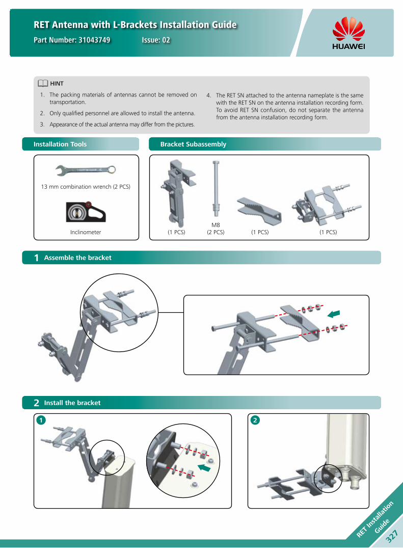
Installation Tools Bracket Subassembly
13 mm combination wrench (2 PCS)
Inclinometer (1 PCS)M8
(2 PCS) (1 PCS) (1 PCS)
1 Assemble the bracket
2 Install the bracket
1 2
RET Antenna with L-Brackets Installation Guide
Part Number: 31043749 Issue: 02
327RET
Installatio
n
Guide
HINT
The packing materials of antennas cannot be removed on 1. transportation.
Only qualified personnel are allowed to install the antenna.2.
Appearance of the actual antenna may differ from the pictures.3.
The RET SN attached to the antenna nameplate is the same 4. with the RET SN on the antenna installation recording form. To avoid RET SN confusion, do not separate the antenna from the antenna installation recording form.

5 Install the antenna
2
1
Ensure the bracket is
fully collapsed at 0°.
RET Antenna with L-Brackets Installation Guide
Part Number: 31043749 Issue: 02
3 Connect the AISG Cable
4 Write Down the Information
Align the convex of the antenna AISG male connector with the concave of the AISG female connector correctly, press the connectors
together, and then secure them by hand properly. For details, see step 2.
Example
Connect the AISG cable. Tighten the AISG cable.
According to the actual situation to fill in the recording form.Taking out the recording form packaging bag.
Protective lid
Remove the AISG protective lid.
AISG Male
Packaging bag
Recording form
CAUTION
In the daisy chain scenario, must write down the information in recording form.1.
Before the filling, please ensure the RET SN attached to the antenna nameplate is the same as the RET SN on the antenna installation 2. recording form.
1
1
2
2
3 Do not remove the 1. protective lid from the antenna AISG female.
Connect the other 2. connector of the AISG cable to the SBT, TMA or RRU.
328
RET Installation
Guide

Any previous catalogue issues become invalid.
Issue: 2012-10-26
HUAWEI TECHNOLOGIES CO., LTD.
Huawei Industrial BaseBantian Longgang
Shenzhen 518129, P.R. ChinaTel: +86-755-28780808
Email: [email protected]
www.huawei.com
Copyright © Huawei Technologies Co., Ltd. 2013. All rights reserved.
THIS DOCUMENT IS FOR INFORMATION PURPOSE ONLY, AND DOSE NOT CONSTITUTE ANY KIND OF WARRANTIES.
In the non-daisy chain scenario, an RET antenna connects with one AISG cable.
In the daisy chain scenario, connect each RET antenna to an AISG cable, then connect the female connector of the upper-level
RET antenna to the male connector of the lower-level RET antenna with an AISG cable. Do not remove the protective lid from the
female connector of the lowest-level RET antenna.
a
b
6 Adjust the mechanical downtilt angle
Adjust the mechanical downtilt angle
Finally, tighten all the nuts.
Recommended torque:
M8 = 18 Nm
Scale of bracket
Precise measurement
Method 1
Method 2
Before adjustment, adjust the
inclinometer to the desired downtilt
angle. After adjustment, locate the bead
in the inclinometer in the middle.
a bNon-Daisy Chain Scenario Daisy Chain Scenario
RET Antenna with L-Brackets Installation Guide
Part Number: 31043749 Issue: 02
329RET
Installatio
n
Guide
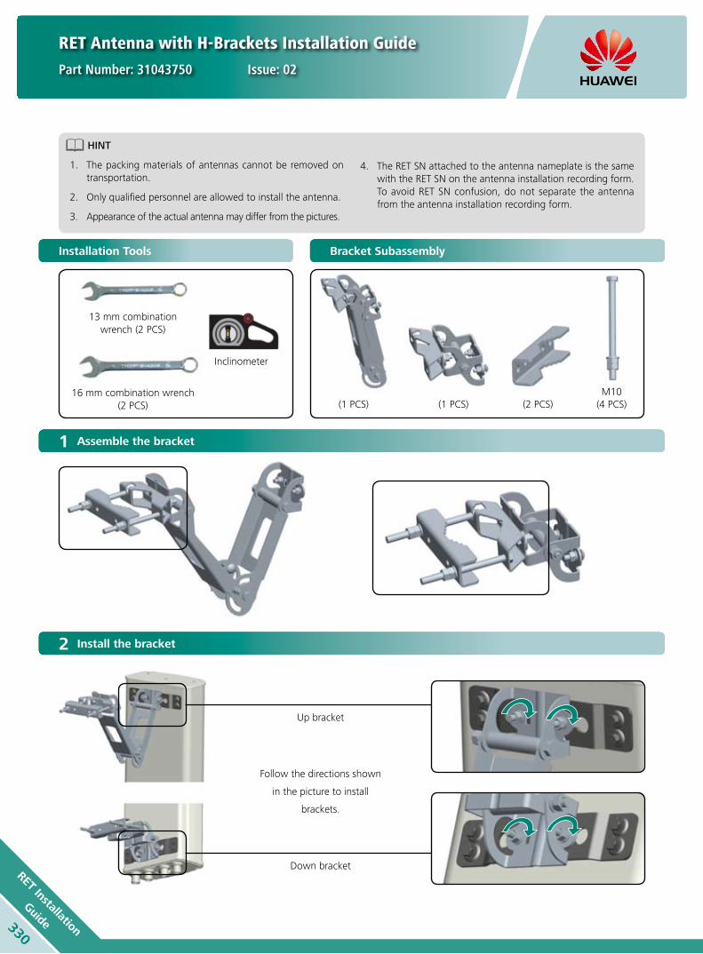
330
RET Installation
Guide
RET Antenna with H-Brackets Installation Guide
Part Number: 31043750 Issue: 02
Installation Tools Bracket Subassembly
13 mm combination wrench (2 PCS)
Inclinometer
(1 PCS)M10
(4 PCS)(2 PCS)(1 PCS)16 mm combination wrench
(2 PCS)
1 Assemble the bracket
2 Install the bracket
Up bracket
Follow the directions shown
in the picture to install
brackets.
Down bracket
HINT
The packing materials of antennas cannot be removed on 1. transportation.
Only qualified personnel are allowed to install the antenna.2.
Appearance of the actual antenna may differ from the pictures.3.
The RET SN attached to the antenna nameplate is the same 4. with the RET SN on the antenna installation recording form. To avoid RET SN confusion, do not separate the antenna from the antenna installation recording form.

331RET
Installatio
n
Guide
5 Install the antenna
RET Antenna with H-Brackets Installation Guide
Part Number: 31043750 Issue: 02
3 Connect the AISG Cable
4 Write Down the Information
Align the convex of the antenna AISG male connector with the concave of the AISG female connector correctly, press the connectors
together, and then secure them by hand properly. For details, see step 2.
Example
Connect the AISG cable. Tighten the AISG cable.
According to the actual situation to fill in the recording form.Taking out the recording form packaging bag.
Protective lid
Remove the AISG protective lid.
AISG Male
Packaging bag
Recording form
CAUTION
In the daisy chain scenario, must write down the information in recording form.1.
Before the filling, please ensure the RET SN attached to the antenna nameplate is the same as the RET SN on the antenna installation 2. recording form.
1
1
2
2
3 Do not remove the 1. protective lid from the antenna AISG female.
Connect the other 2. connector of the AISG cable to the SBT, TMA or RRU.
2
4
1
3
Ensure the bracket is
fully collapsed at 0°.
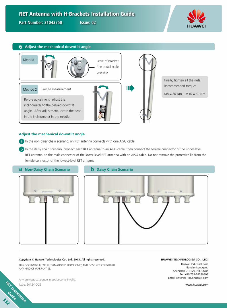
332
RET Installation
Guide
Any previous catalogue issues become invalid.
Issue: 2012-10-26
HUAWEI TECHNOLOGIES CO., LTD.
Huawei Industrial BaseBantian Longgang
Shenzhen 518129, P.R. ChinaTel: +86-755-28780808
Email: [email protected]
www.huawei.com
Copyright © Huawei Technologies Co., Ltd. 2013. All rights reserved.
THIS DOCUMENT IS FOR INFORMATION PURPOSE ONLY, AND DOSE NOT CONSTITUTE ANY KIND OF WARRANTIES.
In the non-daisy chain scenario, an RET antenna connects with one AISG cable.
In the daisy chain scenario, connect each RET antenna to an AISG cable, then connect the female connector of the upper-level
RET antenna to the male connector of the lower-level RET antenna with an AISG cable. Do not remove the protective lid from the
female connector of the lowest-level RET antenna.
a
b
6 Adjust the mechanical downtilt angle
Adjust the mechanical downtilt angle
a bNon-Daisy Chain Scenario Daisy Chain Scenario
RET Antenna with H-Brackets Installation Guide
Part Number: 31043750 Issue: 02
Scale of bracket
(the actual scale
prevails)
Precise measurement
Method 1
Method 2
Finally, tighten all the nuts.
Recommended torque:
M8 = 20 Nm, M10 = 30 Nm
Before adjustment, adjust the
inclinometer to the desired downtilt
angle. After adjustment, locate the bead
in the inclinometer in the middle.

HINT
1. Only qualified personnel are allowed to install the antenna. 2. Appearance of the actual antenna may differ from the pictures.
Installation Tools Bracket Subassembly
13 mm combination wrench (2 PCS)
Inclinometer
(1 PCS)M10
(4 PCS)(2 PCS)(1 PCS)16 mm combination wrench
(2 PCS)
FET Antenna with H-Brackets Installation Guide
Part Number: 31043746 Issue: 02
333FE
T In
stallatio
n
Guide
1 Assemble the bracket
2 Install the bracket
Up bracket
Follow the directions shown
in the picture to install
brackets.
Down bracket

FET Antenna with H-Brackets Installation Guide
Part Number: 31043746 Issue: 02
Any previous catalogue issues become invalid.
Issue: 2012-10-26
HUAWEI TECHNOLOGIES CO., LTD.
Huawei Industrial BaseBantian Longgang
Shenzhen 518129, P.R. ChinaTel: +86-755-28780808
Email: [email protected]
www.huawei.com
Copyright © Huawei Technologies Co., Ltd. 2013. All rights reserved.
THIS DOCUMENT IS FOR INFORMATION PURPOSE ONLY, AND DOSE NOT CONSTITUTE ANY KIND OF WARRANTIES.
4 Adjust the mechanical downtilt angle
3 Install the antenna
334
FET Installation
Guide
Scale of bracket
(the actual scale
prevails)
Precise measurement
Method 1
Method 2
Finally, tighten all the nuts.
Recommended torque:
M8 = 20 Nm, M10 = 30 Nm
Before adjustment, adjust the
inclinometer to the desired downtilt
angle. After adjustment, locate the bead
in the inclinometer in the middle.
2
4
1
3
Ensure the bracket is
fully collapsed at 0°.

FET Antenna with L-Brackets Installation Guide
Part Number: 31043747 Issue: 02
HINT
1. Only qualified personnel are allowed to install the antenna. 2. Appearance of the actual antenna may differ from the pictures.
Installation Tools Bracket Subassembly
335FE
T In
stallatio
n
Guide
13 mm combination wrench (2 PCS)
Inclinometer (1 PCS)M8
(2 PCS) (1 PCS) (1 PCS)
1 Assemble the bracket
2 Install the bracket
1 2

FET Antenna with L-Brackets Installation Guide
Part Number: 31043747 Issue: 02
336
FET Installation
Guide
Any previous catalogue issues become invalid.
Issue: 2012-10-26
HUAWEI TECHNOLOGIES CO., LTD.
Huawei Industrial BaseBantian Longgang
Shenzhen 518129, P.R. ChinaTel: +86-755-28780808
Email: [email protected]
www.huawei.com
Copyright © Huawei Technologies Co., Ltd. 2013. All rights reserved.
THIS DOCUMENT IS FOR INFORMATION PURPOSE ONLY, AND DOSE NOT CONSTITUTE ANY KIND OF WARRANTIES.
3 Install the antenna
2
1
4 Adjust the mechanical downtilt angle
Finally, tighten all the nuts.
Recommended torque:
M8 = 18 Nm
Ensure the bracket is
fully collapsed at 0°.
Scale of bracket
Precise measurement
Method 1
Method 2
Before adjustment, adjust the
inclinometer to the desired downtilt
angle. After adjustment, locate the bead
in the inclinometer in the middle.

337Tr
i-sec
tor C
luster
Installatio
n Gui
de
Tri-sector Cluster Antenna Installation Guide
Part Number: 31043751 Issue: 01
HINT
1. Only qualified personnel are allowed to install the antenna. 2. Appearance of the actual antenna may differ from the pictures.
Installation Tools Fittings
Hoisting ring
Install the hoisting ring on top of the antenna.
Loosen the screw fixing the protective cover.
Tighten the hoisting ring.
Lift the shield up to the position shown by the arrow.
Lightning rod Bolt
1 Preparation before Installation
13 mm combination wrench (2 PCS)
300 x 36 mm Adjustable wrench
16 mm combination wrench (2 PCS)
Phillips screwdriver
2
4
1
3

Tri-sector Cluster Antenna Installation Guide
Part Number: 31043751 Issue: 01
Installing a Cluster Antenna without SBT
a bNon-Daisy Chain Scenario Daisy Chain Scenario
Non-daisy chain scenario: One RCU is
installed in a sector, and RCUs of three
sectors are not connected with each other.
Do not remove the protective cap from
the female connector of the RCU. The
three sectors have the same installation
procedure.
Daisy chain scenario: One RCU is installed in a sector, and RCUs of three sectors are in
daisy chain. Do not remove the protective cap from the female connector on the RCU of
the last sector. For details about how to connect the RCUs in daisy chain mode, see the
RCU Installation Guide.
21 3
a b
c
Remove all protective caps from all DIN connectors and Tilt ports.
Install RF jumpers. Install the RCU. For details about how to install the RCU, see the RCU
Installation Guide.
Sector 1/ Sector 2/ Sector 3
Sector 1 Sector 2
Sector 3
338
Tri-sector Cluster
Installation Guide
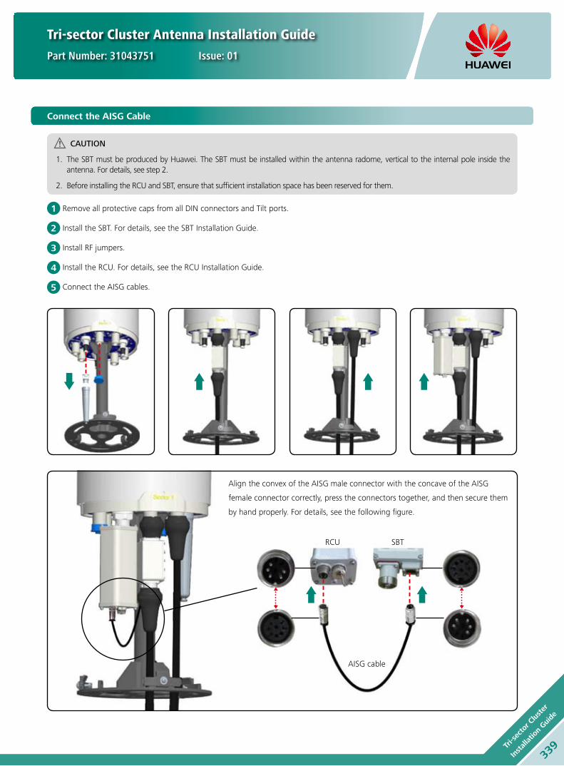
Tri-sector Cluster Antenna Installation Guide
Part Number: 31043751 Issue: 01
Align the convex of the AISG male connector with the concave of the AISG
female connector correctly, press the connectors together, and then secure them
by hand properly. For details, see the following figure.
1
2
3
4
5
Connect the AISG Cable
CAUTION
The SBT must be produced by Huawei. The SBT must be installed within the antenna radome, vertical to the internal pole inside the 1. antenna. For details, see step 2.
Before installing the RCU and SBT, ensure that sufficient installation space has been reserved for them.2.
Remove all protective caps from all DIN connectors and Tilt ports.
Install the SBT. For details, see the SBT Installation Guide.
Install RF jumpers.
Install the RCU. For details, see the RCU Installation Guide.
Connect the AISG cables.
RCU
AISG cable
SBT
339Tr
i-sec
tor C
luster
Installatio
n Gui
de
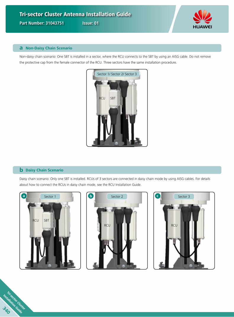
Tri-sector Cluster Antenna Installation Guide
Part Number: 31043751 Issue: 01
a Non-Daisy Chain Scenario
b Daisy Chain Scenario
Daisy chain scenario: Only one SBT is installed. RCUs of 3 sectors are connected in daisy chain mode by using AISG cables. For details
about how to connect the RCUs in daisy chain mode, see the RCU Installation Guide.
Non-daisy chain scenario: One SBT is installed in a sector, where the RCU connects to the SBT by using an AISG cable. Do not remove
the protective cap from the female connector of the RCU. Three sectors have the same installation procedure.
Sector 1/ Sector 2/ Sector 3
Sector 1 Sector 2 Sector 3
RCU
RCU
RCU RCU
SBT
SBT
a b c
340
Tri-sector Cluster
Installation Guide

Tri-sector Cluster Antenna Installation Guide
Part Number: 31043751 Issue: 01
CAUTION
Move the antenna to the mounting platform by using a hoisting ring.
Securing the Antenna
Remove the hoisting ring.
Adjust the azimuth, install the antenna to the mounting frame,
and fix nuts of three sectors.
The concave on the top of the sector silkscreen is the center of the sector. Align the concave with the direction of the determined antenna azimuth.
Install the lightning rod.
Place the protective cover to the bottom of the antenna and lock
screws on the three sectors.
2
4
1
3
Any previous catalogue issues become invalid.
Issue: 2012-10-26
HUAWEI TECHNOLOGIES CO., LTD.
Huawei Industrial BaseBantian Longgang
Shenzhen 518129, P.R. ChinaTel: +86-755-28780808
Email: [email protected]
www.huawei.com
Copyright © Huawei Technologies Co., Ltd. 2013. All rights reserved.
THIS DOCUMENT IS FOR INFORMATION PURPOSE ONLY, AND DOSE NOT CONSTITUTE ANY KIND OF WARRANTIES.
341Tr
i-sec
tor C
luster
Installatio
n Gui
de

Copyright © Huawei Technologies Co., Ltd. 2013. All rights reserved.
No part of this document may be reproduced or transmitted in any form or by any means without prior written consent of Huawei Technologies Co., Ltd.
Trademark Notice
, HUAWEI, and are trademarks or registered trademarks of Huawei Technologies Co., Ltd.
Other trademarks, product, service and company names mentioned are the property of their respective owners.
HUAWEI TECHNOLOGIES CO., LTD.
Huawei Industrial Base
Bantian Longgang
Shenzhen 518129, P.R. China
Tel: +86-755-28780808
Email: [email protected]
Version No.: M3-022337-20130114-C-2.0
www.huawei.com
General Disclaimer
THE INFORMATION IN THIS DOCUMENT MAY CONTAIN PREDICTIVE STATEMENTS
INCLUDING, WITHOUT LIMITATION, STATEMENTS REGARDING THE FUTURE FINANCIAL
AND OPERATING RESULTS, FUTURE PRODUCT PORTFOLIO, NEW TECHNOLOGY, ETC.
THERE ARE A NUMBER OF FACTORS THAT COULD CAUSE ACTUAL RESULTS AND
DEVELOPMENTS TO DIFFER MATERIALLY FROM THOSE EXPRESSED OR IMPLIED IN THE
PREDICTIVE STATEMENTS. THEREFORE, SUCH INFORMATION IS PROVIDED FOR REFERENCE
PURPOSE ONLY AND CONSTITUTES NEITHER AN OFFER NOR AN ACCEPTANCE. HUAWEI
MAY CHANGE THE INFORMATION AT ANY TIME WITHOUT NOTICE.
Current Supply Route
Future Supply Route
Hungary
5 supply centers
2Hubs, 81 service branches
Holland Hub
Brazil
Mexico
Dubai Hub
China
IndiaWestAfrica