14616871 link design 4th chapter in satellite communication
TRANSCRIPT

8/2/2019 14616871 Link Design 4th Chapter in Satellite Communication
http://slidepdf.com/reader/full/14616871-link-design-4th-chapter-in-satellite-communication 1/11
Combining [C/N] & [C/I] values in satellite links: [Overall[C/N]0 ]
The complete satellite circuit consists of an uplink & downlink. When more than one
ratio is present In the link, the individual ratios are added reciprocally to obtain an overall
ratio, i.e., .
This is referred to as the reciprocal formula.
∴ To calculate the performance of a satellite link uplink in the transponder & in
the earth station should be determined. If there are intermodulation products as a result of non-liner
transfer characteristic of the transponder, then the carrier to interference ratio should also be
considered.
From the two [up & down], the overall i.e., can be determined easily using
the following rules:
If the values are equal, is 3dB lower than either value.
If one value is 10 dB smaller than the other, is lower than the smaller of
the values.
If one value is or very greater than the other value, then is equal
to the smaller of the two values. ( Variation), so the will be less than
or equal to smaller value.
Problem
1. Thermal noise in earth station receiver results in a of . A signal is received
from a bent pipe transponder with what is the value of overall at
the earth station? If the transponder introduces intermodulation products with = 24dB,
what is the overall at the receiving earth station?
Solution:

8/2/2019 14616871 Link Design 4th Chapter in Satellite Communication
http://slidepdf.com/reader/full/14616871-link-design-4th-chapter-in-satellite-communication 2/11
Overall (C/N)o with uplink & Downlink attenuation
Most satellite links are designed with link margins to allow for attenuation that may occur in
the link or rise in noise power caused by interference. The effect of a change in the uplink
ratio has a different impact on depending on the type (operating mode) of the
transponder.
Linear transponder:
Non linear transponder:
Regenerative transponder:
[Automatic gain control is used]
Where,
Pin is Power at the transponder input (delivered by satellites receiving antenna)
Pout is Power delivered by transponder to the satellites receiving antenna input.
Gxp is Gain of the transponder.
ΔG is Loss of gain caused by the non-linear saturation characteristics of the transponder.
Uplink & Downlink Attenuation in Rain
Rain attenuation affects uplink & downlinks differently. It is usually assumed that rain
attenuation occurs on either the downlink or the uplink, not on both at the same time. This is true for
earth station that are well separated geographically, but not if they are close (< 20 Km).

8/2/2019 14616871 Link Design 4th Chapter in Satellite Communication
http://slidepdf.com/reader/full/14616871-link-design-4th-chapter-in-satellite-communication 3/11
(C/N)0 Uplink
Rain attenuation on the uplink path to the satellite reduces the power at the satellite receiver
input & thus reduces in direct proportion to the attenuation on the link.
i) If the transponder is of linear type,
ii) Non-linear transponder,
iii) for regenerative transponder or AGC,
Downlink Attenuation & (C/N)dn
The earth station receiver noise temperature can change significantly when rain is present in
the downlink path from the satellite. The sky noise temperature can increase to close to the physical
temperature of individual rain drops in heavy rain.
The overall is then given by,
Satellite communication link design procedure:
1. Determine the frequency band in which the system must operate comparative designs can be
used for better selection.
2. Determine the communication parameters of the satellite. Estimate any values that are not
known.3. Determine the parameters of the transmitting & receiving earth station.
4. Start at the transmitting earth station. Establish an uplink budget & a transponder noise power
budget to find (C/N)up in the transponder.
5. Find the out put power of the transponder based on transponder gain or output back off.
6. Establish a downlink power & noise budget for the receiving earth station. Calculate
(C/N)down & (C/N)o for a station at the edge of the coverage zone (worst case).
7. Calculate S/N or BER in the base band channels. Find the link margins.

8/2/2019 14616871 Link Design 4th Chapter in Satellite Communication
http://slidepdf.com/reader/full/14616871-link-design-4th-chapter-in-satellite-communication 4/11
8. Evaluate the result & compare with the specification requirements change parameters of the
system as required to obtain acceptable (C/N)0 or S/N or BER values. This requires several
trial designs.
9. Determine the propagation conditions under which the link must operate, calculate outage
times for the uplink & downlinks.
10. Reducing the system by changing some parameters if the link margins are inadequate. Check
that all parameters are reasonable & that the design can be implemented within the expected
budget.
System Design Problems
1. The specified parameters of a down link are satellite saturation EIRP = 25dBW, output back off 6
dB, freespace loss 96dB, allowance for other downlink losses 1.5dB, earth station G/T is 4 dB/K.
Calculate the carrier to noise density ratio at the earth station.
Solution:
[C/N0 ] = [EIRP] + [G/T] – [FSL] – [k] – [Lm]
density {[EIRP]sat – [B0]0 }.
Tabulation method (with minus sign for FSL, k & Lm),
Satellite saturation EIRP 25 dB W
Earth station[G/T] 41.0Free space loss (FSL) -196
K 228.6[-(-k)] – (-228.6) = + 228.6.
Other losses(Lm) -1.5
Output backoff BO0 -6.0
Total [C/N0] dnlink = 91.1
System & satellite specifications:
Ku-band satellite parameters:
Geostationary at 73w longitude, 28 ku-band transponders
Total RF output power = 2.24kw
Antenna gain (transmit & receiver) = 31 db = G
Receiver system noise temperature = 500k = TS
Transponder saturated output power = 80w = Psat
Transponder bandwidth = 54 MHz.Signal : Compressed digital videos signal with transmitted symbol rate at 43.2 Msps.
Minimum permitted overall (C/N)0 in the receiver = 9.5 dB.

8/2/2019 14616871 Link Design 4th Chapter in Satellite Communication
http://slidepdf.com/reader/full/14616871-link-design-4th-chapter-in-satellite-communication 5/11
Transmitting Ku-band earth station
Antenna diameter = 5m = D
Aperture efficiency = 68% = ηe
Uplink frequency = 14.15GHz = f up
Required C/N in Ku-band transponder = 30 dB = (C/N)up
Transponder HPA output backoff = 1 dB = [BO]0
Miscellaneous uplink losses = 0.3 dB.
Location : -2 dB contour of satellite receiving antenna = Lpt
Receiving KU-band earth station:
Downlink frequency = 11.45GHz = f dn
Receiver If noise bandwidth = 43.2 MHz = B N
Antenna noise temperature = 30k = Tin = TA
LNA noise temperature = 110k = TLNA= TRF
Required overall (C/N)0 in clear air = 17 dB = (C/N)0
Miscellaneous downlink losses = 0.2 dB
Location : -3 dB contour of satellite transmitting antenna = Lpt
Rain attenuation & propagation factors
Ku-band clear air attenuationUplink (14.15 GHz) = 0.7dB
Downlink (11.45 GHz) = 0.5 dB
Rain attenuation
Uplink 0.01% of year =6 dB
Downlink 0.01% of year =5 dB
DESIGN
This example examines the design of a satellite communication link using a ku-band
geostationary satellite with bent pipe transponder to distribute digital TV signals from an earth
station to many receiving stations.
Ku-Band Uplink Design
The first step is find out the uplink transmitter power required to achieve (C/N)up = 30 dB in
clear air atmospheric conditions. Noise power is determine first, which is then added to (C/N) to get
[C]
Uplink Noise Power Budget
8/2/2019 14616871 Link Design 4th Chapter in Satellite Communication
http://slidepdf.com/reader/full/14616871-link-design-4th-chapter-in-satellite-communication 6/11
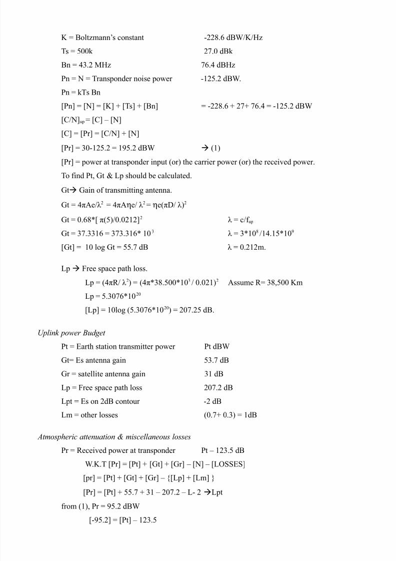
K = Boltzmann’s constant -228.6 dBW/K/Hz
Ts = 500k 27.0 dBk
Bn = 43.2 MHz 76.4 dBHz
Pn = N = Transponder noise power -125.2 dBW.
Pn = kTs Bn
[Pn] = [N] = [K] + [Ts] + [Bn] = -228.6 + 27+ 76.4 = -125.2 dBW
[C/N]up = [C] – [N]
[C] = [Pr] = [C/N] + [N]
[Pr] = 30-125.2 = 195.2 dBW (1)
[Pr] = power at transponder input (or) the carrier power (or) the received power.
To find Pt, Gt & Lp should be calculated.
Gt Gain of transmitting antenna.
Gt = 4πAe/λ 2 = 4πAηe/ λ 2 = ηe(πD/ λ)2
Gt = 0.68*[ π(5)/0.0212]2 λ = c/f up
Gt = 37.3316 = 373.316* 103 λ = 3*108 /14.15*109
[Gt] = 10 log Gt = 55.7 dB λ = 0.212m.
Lp Free space path loss.
Lp = (4πR/ λ 2) = (4π*38.500*103 / 0.021)2 Assume R= 38,500 Km
Lp = 5.3076*1020
[Lp] = 10log (5.3076*1020) = 207.25 dB.
Uplink power Budget
Pt = Earth station transmitter power Pt dBW
Gt= Es antenna gain 53.7 dB
Gr = satellite antenna gain 31 dB
Lp = Free space path loss 207.2 dB
Lpt = Es on 2dB contour -2 dB
Lm = other losses (0.7+ 0.3) = 1dB
Atmospheric attenuation & miscellaneous losses
Pr = Received power at transponder Pt – 123.5 dB
W.K.T [Pr] = [Pt] + [Gt] + [Gr] – [N] – [LOSSES]
[pr] = [Pt] + [Gt] + [Gr] – {[Lp] + [Lm] }
[Pr] = [Pt] + 55.7 + 31 – 207.2 – L- 2Lpt
from (1), Pr = 95.2 dBW
[-95.2] = [Pt] – 123.5

8/2/2019 14616871 Link Design 4th Chapter in Satellite Communication
http://slidepdf.com/reader/full/14616871-link-design-4th-chapter-in-satellite-communication 7/11
[Pt] = 28.3 dBW
(or) Pt = 676W.
This is relatively high power, so the transmitting antenna diameter is increased there by increasing its
gain (Pt)
Ku-band Downlink Deign
The first step is to calculate (C/Ndn that will provide (C/N)0 = 17dB
When (C/N)up = 30 dB.
(C/N)up = 30 dAB = 1000
(C/N)0 = 17 dB – 101.7
= 50
(or) 1/(C/N)dn = 1/(C/N)0 – 1/(C/N)up
1/(C/N)dn = 1/50 – 1/100
(C/N)dn = 52.63 [C/N]dn = 10log 52.63 = 17.2 dB
Next step is to find the required receiver input power to give (C/N)dn = 17.2 dB
& then find the receiving antenna gain, Gr.
Down link noise power budget
K= -228.6 dB W/K/Hz
Ts = TLNA+ Tin = 110 + 30 = 140K = 21.5 dBK
Bn = 43.2 MHz = 76.4 dBHz.
[Pn] = [N]dn = [K] + [Ts] + [Bn] = -228.6 + 21.5 + 76.4 = -130.7 dB W
[C/N]dn = [C]dn – [N]dn
[C] = [C/N]dn + [N]dn
[C] = 17.2 + (-130.7) = -113.5 dBW (2)
[C] = [Pr] Power at earth station receiver input .
Lp Path Loss.
[Lp] = 10log (4πR/ λ)2 λ = C/f
[Lp] = 20log [4π* 38500* 103 /0.0262 ] λ = 3*108 / 11.45 GHz = 0.00262m
[Lp] = 205.3 dB.
The transponder is operated with 1 dB output backoff, so the output power is 1 dB below the
saturated power.
Psat = 80 W [Psat ] = 19 dBW

8/2/2019 14616871 Link Design 4th Chapter in Satellite Communication
http://slidepdf.com/reader/full/14616871-link-design-4th-chapter-in-satellite-communication 8/11
[Pt] = [Ptsat ] – [Bo]0 = 19-1= 18 dBW.
Downlink power budget:
Pt = Satellite transponder o/p power 18 dBW
Gt = Satellite antenna gain 31 dB
Gr = ES antenna gain [Gr ] dB
[Lp] = path loss 205.3 dB
L pt = E/s on -3 dB contour of sat antenna -3 dB
Lm = other losses = 0.2 + 0.5 = 0.7 dB.
Miscellaneous loss Absorption in atmosphere
Pr = Received power at transponder.
[Pr ] = [Pt] + [Gt] + [Gr ] – [L p] + [Lm] +L pt
[Pr] = 18 + [Gr] + 31 – 205.3 – 0.7 -3
[Pr] = [Gr] – 160
[Gr] = [Pr] + 160 = -113.5 (From(2))
[Gr] = 46.5 dB= 44668.3
Diameter
Gr = (πD/ λ)2 x ηe D2 = Gr λ 2 / 6π2 * ηe = 44668.3*0.02622 / π2 * 0.65 D = 2.18m
D = 2.18m Diameter of the receiving antenna.
Rain effects at Ku-band.
1) Uplink.
Under conditions of heavy rain, the Ku-band path to the satellite station suffers an
attenuation of 6dB for 0.01% of the year.
The (C/N)up = 30 dB in clear air. If we assume a linear characteristic transponder, then [C/N] up rain =
[C/N]upca - [A] rain
[C/N] uprain = 30-6 = 24 dB.
The overall [C/N] also falls by 6 dB, [C/N]0rain = 17-6 11dB
But this is grater than the min C/N of 9.5 dB
Additional margin is 1.5 dB.
Total margin available on uplink is 1.5 + 6 = 7.5 dB
2) Downlink:
The 11.45 GHz path between the satellite & receive station suffrs rain attenuation of 5 dBfor 0.01% of the year.
The sky noise temperature because of rain fall is,

8/2/2019 14616871 Link Design 4th Chapter in Satellite Communication
http://slidepdf.com/reader/full/14616871-link-design-4th-chapter-in-satellite-communication 9/11
Tskyrain = T0 (1- Gl) Gl< 1
Total attenuation = [A]absorption + [A] rain
[A] = 0.5 + 5.0 = 5.5 dB.
Gl = 1/100.55 = 0.282.
∴ Tsky rain = 270 (1-0.282) = 194K = TA = Tin .
Thus, the antenna noise temperature has increased from 30K in clear air to 194k in rain.
Ts rain = Ts sky + TLNA= Tin + TRF
Ts rain = 194 + 110 = 304k 24.8 dBk.
The increase in noise power,
[ΔN]rain 10 log (Ts rain/Ts ca) Tsca = Tin + TRF = 30 + 110 – 140k
[ΔN] rain = 10 log (304/140) = 3.4 dB
∴ [C/N]dn rain = [C/N]ca dn – [A]rain – [ΔN] rain = 17.2 – 5- 3.4
[C/N] dn rain = 8.8 dB = 7.585
W.K.T
∴
which is less than the min (C/N) i.e., 9.5 dB.
So, we will find the max tolerable attenuation, (trials error method)
Let [A] rain be equal to 4.7 dB.
Tskyrain = 178k, ΔN rain = 10 log (178+110/ 140) = 3.1 dB
(C/N)dn rain = 9.36 ≈ 9.4 dB (almost equal to C/N min 9.5 dB)
1. An LNA is conducted rain receiver
F= 12 dB = 15.85.
Tn = T =T0 (F-1) = 290(15.85-1) = 4306k (receiver)
Ts (or) GLNA, Ts= TRF + Tn/GRF
Ts = 120 + 4306/104 = 120.43K.
2. A parabolic dish antenna having a mouth diameter of 20m & an aperture efficiency of 90%
produces a radiated beam with a solid angel of 3*10-4 steradians. Determine the antenna’s power gain
in dB, & also the operational frequency.
Beam solid angle = Ω = 3*10-4 steriadians.

8/2/2019 14616871 Link Design 4th Chapter in Satellite Communication
http://slidepdf.com/reader/full/14616871-link-design-4th-chapter-in-satellite-communication 10/11
Operational frequency, f= c/ λ = 3*108 /0.291 = 1.03 GHz
The following fig shows a cascaded arrangement of three gain blocks.
It is given that G1= 106 & its noise temperature Te1 = 100k, G2 = 104
Te2= 60k, G3 100 & Te3 = 20k. Determine the equivalent noise temperature of the cascaded
arrangement.
Tc
Te = Te + Te2 / G1 + Te3 /G1 G2
Te = 100 + 60/106 + 20/106 *104
Te ≅ 100k.
The following fig shows the cascaded arrangement of four gain 5lods with their gain & noise figures
as G1 = 100, F1 = 2, G2 = 10, F2 = 10, G3 = 10, F3 = 1,
G4 = 10, F4 = 20. Determine the noise figure of the cascaded arrangement.
The overall noise figure,
F= F1 + (F2 -1/G1) + (F3 -1/G1 G2) + (F4 -1/G1 G2 G3)
F = 2 + (10-1/100) + 100 (15-1)/100*10 + 20-1/100*10*10
F = 2.1059 = 3.2 dB.
5) The following fig shows the reciver side of satellite earth station. Determine the earth station
system noise temperature & (G/T) referred to the i/p of the low noise amplifier. To = 290k.
TA = 60k
Gr = 66dB Waveguide LNA Mixer
L- 1.075 160k,106
10,000k.
Ts = (TA * Gl) + Tp (1 – Gl ) + TLNA+ Tm/GLNA Gl = 1/1.075 = 0.93
= (60*0.93) + 290 (1 – 0.93) + 160 + 10,000/ 106
Ts = 160.01 + 76.04 = 236.05K.
At LNA i/p
Ts = Ts LNA/Gl = 236.05/0.93 = 253.75 k
(or w/g i/p)
Antenna gain referred to LNA i/p is,
G = 66 – 0.3 = 65.7 dB

8/2/2019 14616871 Link Design 4th Chapter in Satellite Communication
http://slidepdf.com/reader/full/14616871-link-design-4th-chapter-in-satellite-communication 11/11
(loss in wave guide)
[G/T] = 65.7 [10 log 236.05] = 65.7 – 23.73
[G/T] = 41.97 dB/K.
referred to LNA i/p.