15 - ge grid · pdf fileis required for all types of short circuits and for any fault...
TRANSCRIPT
322 LINE PROTECTION WITH PILOT RELAYS
Pilot relaying is the best type for line protection. It is used whenever high-speed protectionis required for all types of short circuits and for any fault location. For two-terminal lines,and for many multiterminal lines, all the terminal breakers are tripped practicallysimultaneously, thereby permitting high-speed automatic reclosing. The combination ofhigh-speed tripping and high-speed reclosing permits the transmission system to beloaded more nearly to its stability limit, thereby providing the maximum return on theinvestment.
The continuing trend of increasing circuit-breaker-interrupting capabilities is increasingthe allowable magnitude of short-circuit current. It is quite possible that damage ratherthan stability may dictate high-speed relaying in some cases.
Pilot relaying is used on some multiterminal lines where high-speed tripping and reclosingare not essential, but where the configuration of the circuit makes it impossible for distancerelaying to provide even the moderate speed that may be required.
Some lines are too short for any type of distance relay. For such lines, it is not merely amatter of getting a distance relay with a lower minimum ohmic adjustment; the ohmicerrors would be so high as compared with the ohms being measured that such relayingwould be impractical.
Critical loads may require high-speed tripping beyond the capabilities of distance relays.11
For these reasons, it is the practice to use pilot relaying for most high-voltage transmissionlines and for many subtransmission and distribution circuits. Therefore, it becomesnecessary to choose between wire pilot, carrier-current pilot, and microwave pilot.2 If eitherof the last two is indicated, one has to choose further between phase comparison anddirectional comparison, or a combination of the two. In addition to any of these, someform of remote tripping may be required. The application considerations of these variousequipments will now be discussed.
WIRE-PILOT RELAYING
Chapter 5 tells why d-c wire-pilot relaying has largely given way to a-c types. In this chapter,we shall consider the application of only the a-c types.
Wire-pilot relaying is used on low-voltage circuits, and on high-voltage transmission lineswhen a carrier-current pilot is not economically justifiable. For the protection of certainpower-cable circuits, wire pilot may be used because the cable-circuit attenuation is too
15LINE PROTECTION WITH PILOT RELAYS

LINE PROTECTION WITH PILOT RELAYS 323
high for carrier current. For short lines, a-c wire-pilot relaying is the most economical formof high-speed relaying.
Generally, wire pilots no longer than about 5 to 10 miles are used, but there are a few inservice as long as about 27 miles.3 As mentioned in Chapter 5, the technical limitations onthe length of a pilot circuit are its resistance and shunt capacitance. Compensatingreactors are sometimes used when the shunt capacitance is too high. A pilot circuit that isrented from the telephone company may be much longer than the transmission line forwhose protection it is to be used, because such telephone circuits seldom run directlybetween the line terminals. Therefore, in borderline cases, one should find out the actualresistance and capacitance before deciding to use wire pilot. Other requirements imposedon the wire-pilot circuit are described in Chapter 5.
In general, wire-pilot relaying is not considered as reliable as carrier-current-pilot relaying,mostly because many of the wire-pilot circuits that are used are not very reliable. The pilotcircuit represents so much exposure to the possibility of trouble that great care should betaken in its choice and protection.
OBTAINING ADEQUATE SENSITIVITY
Apart from making sure that associated equipment is suitable for the application, theprincipal step in the application procedure is to determine if the available adjustments ofthe relaying equipment are such that the necessary sensitivity and speed are assured.Manufacturers’ bulletins describe how to do this when one knows the maximum andminimum fault-current magnitudes for phase and ground faults at either end of the line.
It is advisable not to adjust the equipment to have much greater sensitivity than is requiredor else, in so doing, the CT’s may be burdened excessively. With excessive burden, the over-all sensitivity may be poorer, as illustrated by Problem 2 of Chapter 7.
If the phase-fault currents are high enough to permit it, it is advisable to adjust the phase-fault pickup to be at least 25% higher than maximum load current. Then, the equipmentwill not trip its breakers undesirably on load current should the pilot wires become open-circuited or short-circuited. Undesirable tripping could still occur for an external fault,unless supervising equipment is used to forestall such tripping.
Fig. 1. Illustrating a blocking-terminal application.

324 LINE PROTECTION WITH PILOT RELAYS
THE PROTECTION OF MULTITERMINAL LINES
When there are sources of generation back of more than two terminals, or if there aregrounded-neutral wye-delta power-transformer banks at more than two terminals, theapplication requires a careful study of the available short-circuit currents under variousgenerating conditions to determine if the necessary sensitivity can be assured. The moresource terminals there are, the less sensitive will the protection be.4
When there are sources of generation back of only two terminals as in Fig. 1, the problemis much simplified. A terminal that has no source of generation is treated as a so-called“blocking” terminal. Instantaneous overcurrent relays energized from CT’s on the high-
voltage sideofeachblockingterminal are connectedeither to open-circuit or to short-circuitthe pilot wires, depending on the type of wire-pilot relaying used, to block tripping at themain terminals for a low-voltage fault at the blocking terminal. The operating time of thetripping relays at the main terminals must be coordinated with that of the blocking-terminal relays. The overcurrent-relay contacts operate in the secondary of an insulatingtransformer, as in Fig. 2. It is necessary to energize the blocking relays from high-voltageCT’s so that tripping at the source terminals will also be blocked for magnetizing-currentinrush. The blocking relays should not be sensitive enough to operate on the current fedback to high-voltage faults by motors on the low-voltage side of the blocking terminal, orelse tripping at the main terminals will be delayed.
Blocking-terminal equipment will not trip the local breaker for high-voltage line faults;such tripping may be necessary if automatic reclosing is used at the source terminals of theline and if there are motors at the blocking terminal that might be damaged by suchreclosing. If high-speed reclosing is used at the source terminals, the breaker at theblocking terminal must be tripped, when necessary, by remote tripping from both sourceterminals. If the automatic reclosing is slow enough, the breaker could be tripped by localundervoltage or underfrequency relays.
Fig. 2. Blocking-terminal technique.

LINE PROTECTION WITH PILOT RELAYS 325
If a blocking-terminal power-transformer bank is large enough to justify differentialrelaying, remote tripping of the source terminals for transformer faults would be used ifthere were no high-voltage breakers at the blocking terminal, as is usually true.5 Otherwise,the bank would be protected only by fuses on the high-voltage side.
For the blocking-terminal technique to be permissible, the total load current of allblocking terminals on the line must be less than the current required to operate the wire-pilot relays at one source terminal of the line with the breaker at the other source terminalopen.
If the power-transformer banks are small enough at the load terminals behind which thereis no generation, the wire-pilot relays at the source terminals could be adjusted not tooperate for low-voltage faults at the load terminals. This would also probably preventoperation on magnetizing-current inrush, particularly if the ground-fault pickup could bemade high enough.6 This would eliminate the need for any blocking-terminal equipment.
A multiterminal line can sometimes be well protected against ground faults with wire-pilotrelaying, even though adequate phase-fault protection is impossible. This is because linetaps are usually made through delta-wye power-transformer banks, and they are opencircuits so far as zero-phase-sequence currents on the high-voltage side are concerned.Therefore, if the wire-pilot relays are arranged to receive only the CT neutral current, sucha multiterminal line may be treated as a two-terminal line. Good protection against phasefaults on such a line can often be provided by distance relays because the impedance of thetransformer at each tap is so high that the distance relays can usually be adjusted to protect80% to 90% of the line without reaching through any of the transformers.
CURRENT-TRANSFORMER REQUIREMENTS
Conventional a-c wire-pilot relays have variable percentage-differential characteristics thatpermit large CT ratio errors at high magnitudes of external-fault currents. Usually, it isonly necessary to be sure that the CT’s are able to supply the required current to operatethe relays at high speed when internal faults occur. This is a matter involving the relayburdens for the sensitivity taps used, the pilot-wire resistance, and the characteristics of theCT’s.
The equipment may also contain adjustment to compensate for the nominal CT ratio atone terminal differing from that at another terminal. In borderline cases, this adjustmentmight increase a tendency to operate undesirably for external faults because of transientdifferences between CT errors; therefore, in general, the same nominal CT ratios at allterminals are preferred.
If a line terminates in a power-transformer bank with no high-voltage breaker, the relayingequipment should be energized from high-voltage CT’s–generally bushing CT’s in thetransformer bank. If low-voltage CT’s were used, they would have to be connected so as tocompensate for the phase shift caused by the power transformer and, possibly, to removezero-phase-sequence components. The objection to low-voltage CT’s is that the relayingequipment will operate to trip undesirably on magnetizing-current inrush either when thetransformer bank is energized or when system disturbances occur. To avoid suchobjectionable operation would require additional relaying equipment. Also, some types ofa-c wire-pilot relays would not respond to faults between a particular pair of phases.
326 LINE PROTECTION WITH PILOT RELAYS
BACK-UP PROTECTION
Wire-pilot relaying does not provide back-up protection. Separate overcurrent or distancerelays are used for this purpose. When wire-pilot relaying is applied to an existing line, it isoften the practice to use the existing relaying equipment for back-up protection.
Distance relays may be used for back-up protection even though the line is too short to usedistance relays for primary protection. In such a case, the high-speed zone would be madeinoperative.
When directional-overcurrent relays are used for back-up protection, the requirements onthe voltage source are the least severe, and uncompensated low-tension voltage can beused. It will be noted that the conventional type of a-c wire-pilot-relaying equipment doesnot use any a-c voltage.
CARRIER-CURRENT-PILOT RELAYING
Carrier-current-pilot relaying is the best and most commonly used kind of relaying forhigh-voltage lines. A report7 showed that this kind of relaying is in service on lines whosevoltage is as low as 33 kv. It is applicable in some form to any aerial line. Carrier-current-pilot relaying is preferred to wire-pilot relaying because it is somewhat more reliable and ismore widely applicable. Consisting entirely of terminal equipment, it is completely underthe control of the user, as contrasted with rented wire pilot. Also, the carrier-current pilotlends itself more conveniently to joint usage by other services such as emergency telephonyand remote trip.
AUTOMATIC SUPERVISION OF THE CARRIER-CURRENT CHANNEL
When carrier-current-pilot relaying was first introduced, the reliability of vacuum tubes wasnot as good as it is now, and some users felt the need for automatic equipment to supervisethe pilot channel. Today, users are content to rely on the manual tests that are made dailyat various regular intervals because the carrier-current channel has proved to be a veryreliable element of the protective equipment.7
CARRIER-CURRENT ATTENUATION .
Every proposed application should be studied to be sure that the losses, or attenuation, inthe carrier-current channel will be within the allowable limits of the equipment.8
Manufacturers’ publications specify these limits and describe how to calculate theattenuation in each element of the channel.9
The protection of multiterminal lines requires very careful scrutiny of the attenuation.Depending on the length of line tapped from the main line, “reflections” from a tap maycause excessive attenuation unless the carrier-current frequency is very carefully chosen. Ifthis length is 1/4, 3/4, 5/4, 7/4, 9/4, etc., wavelengths, excessive attenuation may be expected.Sometimes, only a test with carrier current of different frequencies will supply the requiredinformation.10 In extreme cases, it is necessary to install line traps in the taps to eliminatereflections.

LINE PROTECTION WITH PILOT RELAYS 327
Power cable causes very high carrier-current attenuation, particularly where sheath-bonding transformers are used. Also, the so-called “mismatch,” or discontinuity in theimpedance characteristic of the channel where power cable connects to overhead line,causes high loss.1l It is usually possible to use carrier current only on short lengths of cable,and then only with frequencies near the low end of the range. Because of the foregoing,wire pilot, or even microwave pilot, is sometimes used where carrier current mightotherwise be preferred.
USE OF CARRIER CURRENT TO DETECT SLEET ACCUMULATION
The carrier-current channel provides a method for determining when sleet accumulationrequires sleet melting to be started. This method has had varied reception among electricutilities.l2 It is generally agreed that the method indicates sleet accumulation, but it willalso occasionally give false indication during fog, mist, or rain. Those who use this methodof sleet detection feel that the extra cost incurred as a result of going through the sleet-melting process unnecessarily because of such false indications is small and is justified ona “fail-safe” basis.
The method of detecting sleet accumulation is based on the fact that the attenuation of atransmission line increases as sleet accumulates on the line. Figure 3 shows the effect ofattenuation on the magnitude of the output from the carrier-current receiver. Normaloperation is represented by the point A. The safety factor in the equipment, when it isproperly applied, is sufficient so that under the most adverse atmospheric conditions,including sleet, the attenuation would not greatly exceed that represented by the point B.
Therefore, the reliability of the equipment is assured under all conditions. Now, when it isdesired to detect sleet accumulation, the operator at one end of the line causes carriercurrent to be transmitted, and the operator at one end or the other presses a button tointroduce attenuation into the transmitter or receiver circuit so as to advance the normaloperating position from A to B. Then, the receiver output decreases rapidly for anyadditional attenuation due to sleet. When conditions appear to be favorable for sleet, sucha test at frequent intervals will detect increases in sleet accumulation. Such informationmust be coordinated with visual observation and experience before the receiver-outputreadings have any useful meaning.
This sleet-detection feature also detects accumulation of dirt or salt on the line insulators,and deterioration of vacuum tubes. It is used for this purpose by many companies that donot use it for sleet detection.
Fig. 3. Effect of attenuation on the strength of the receiver-output signal.

328 LINE PROTECTION WITH PILOT RELAYS
TYPES OF RELAYING EQUIPMENT
The three types of carrier-current-pilot-relaying equipment in regular use are phasecomparison, directional comparison, and combined phase and directional comparison.Each of them will be treated in the following material.
PHASE COMPARISON
Phase-comparison relaying is much like a-c wire-pilot relaying. It is the simplestconventional type of carrier-current-pilot-relaying equipment. However, its bestapplication is to two-terminal lines; multiterminal-line applications require very carefulexamination, and the sensitivity of the protection is quite inferior to that for two-terminallines. Even for two-terminaI lines, the phase-fault sensitivity of phase comparison is not asgood as that of directional comparison.
The ideal application of phase comparison is to a two-terminal line that one is sure will notbe tapped later, and where the fault-current magnitudes are high enough to assure high-speed tripping under all likely conditions of system operation.
The fact that phase-comparison relaying does not use a-c voltage (except for testing) mayor may not be an advantage, depending on the type of back-up relaying that is used. Ifdistance relays are used for back-up, the same quality of voltage source is required as fordirectional-comparison relaying. It is only when overcurrent relaying (possibly directional)is used for back-up protection that phase-comparison relaying enjoys any advantage fromnot using a-c voltages.
Phase-comparison relaying is unaffected by mutual induction from neighboring powercircuits. This is an advantage over directional comparison. This subject is treated in moredetail later under the heading “Combined Phase and Directional Comparison.”
The fact that any back-up-relaying equipment that may be used is entirely separate fromthe phase-comparison equipment is an advantage of phase comparison. One equipmentmay be taken out of service for maintenance without disturbing the other in any way.
An excellent comparison of phase and directional-comparison relaying is given inReference 13.
OBTAINING ADEQUATE SENSITIVITY
Apart from making sure that the carrier-current attenuation is not too high, and thatassociated equipment is suitable for the application, the principal step in the applicationprocedure is to determine if the available adjustments of the relaying equipment are suchthat the necessary sensitivity and speed are assured. Manufacturers’ bulletins describe howto do this when one knows the maximum and minimum fault-current magnitudes forphase and ground faults at either end of the line..
It is advisable not to adjust the equipment to have much greater sensitivity than is requiredor else, in so doing, the CT’s may be burdened excessively. With excessive burden, the over-all sensitivity might be poorer, as illustrated by Problem 2 of Chapter 7. Or, if theground-fault sensitivity is too high, the equipment might misoperate on “false residual
LINE PROTECTION WITH PILOT RELAYS 329
currents”6 caused by CT errors because of external-fault current having a large d-c offset,or because of differences in residual flux.
In practice the equipment is usually adjusted so that carrier current is not generated unlessthe phase-fault current exceeds the maximum load current. The purpose of this is toprolong the life of the vacuum tubes and to make the carrier-current channel available forother services when it is not required for relaying. Because the pickup of the tripping faultdetectors must be higher than the pickup of the blocking fault detectors, the trippingpickup will be still higher above maximum load; in fact, the reset value of the tripping faultdetectors must be a safe margin above the pickup of the blocking fault detectors. With suchadjustment, failure of the carrier-current channel will not cause undesired tripping underload; however, undesired tripping could occur for an external fault if the channel failed.
THE PROTECTION OF MULTITERMINAL LINES
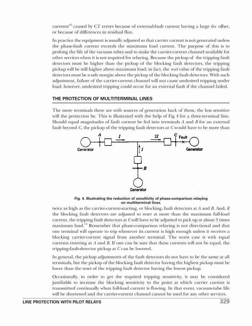
The more terminals there are with sources of generation back of them, the less sensitivewill the protection be. This is illustrated with the help of Fig 4 for a three-terminal line.Should equal magnitudes of fault current be fed into terminals A and B for an externalfault beyond C, the pickup of the tripping fault detectors at C would have to be more than
twice as high as the carrier-current-starting, or blocking, fault detectors at A and B. And, ifthe blocking fault detectors are adjusted to reset at more than the maximum full-loadcurrent, the tripping fault detectors at C will have to be adjusted to pick up at about 3 timesmaximum load.14 Remember that phase-comparison relaying is not directional and thatone terminal will operate to trip whenever its current is high enough unless it receives ablocking carrier-current signal from another terminal. The worst case is with equalcurrents entering at A and B. If one can be sure that these currents will not be equal, thetripping-fault-detector pickup at C can be lowered.
In general, the pickup adjustments of the fault detectors do not have to be the same at allterminals, but the pickup of the blocking fault detector having the highest pickup must belower than the reset of the tripping fault detector having the lowest pickup.
Occasionally, in order to get the required tripping sensitivity, it may be consideredjustifiable to increase the blocking sensitivity to the point at which carrier current istransmitted continually when full-load current is flowing. In that event, vacuum-tube lifewill be shortened and the carrier-current channel cannot be used for any other services.
Fig. 4. Illustrating the reduction of sensitivity of phase-comparison relayingon multiterminal lines.
330 LINE PROTECTION WITH PILOT RELAYS
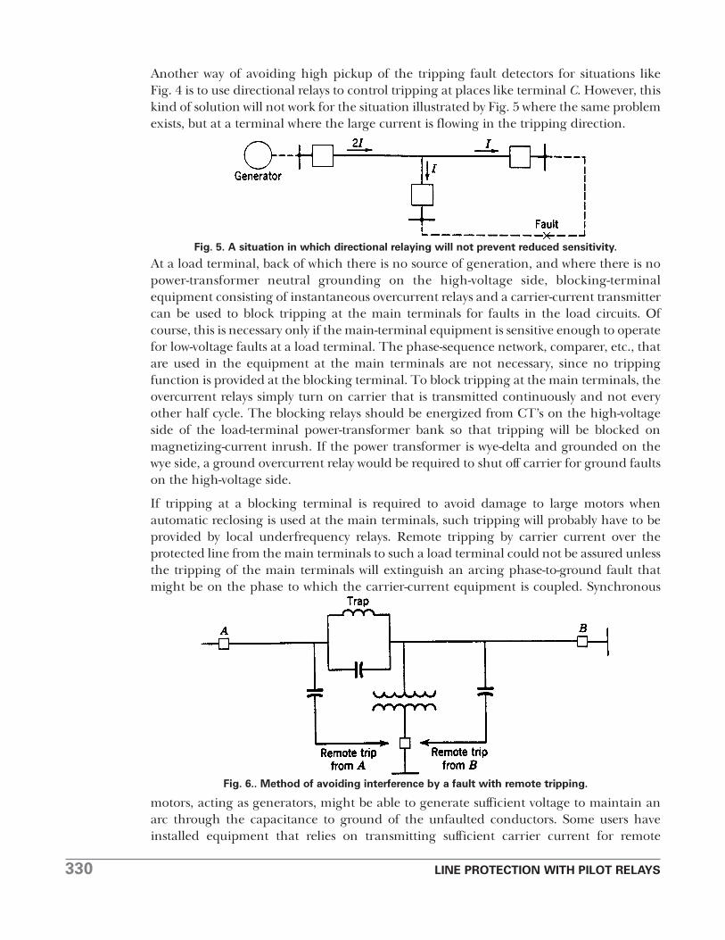
Another way of avoiding high pickup of the tripping fault detectors for situations likeFig. 4 is to use directional relays to control tripping at places like terminal C. However, thiskind of solution will not work for the situation illustrated by Fig. 5 where the same problemexists, but at a terminal where the large current is flowing in the tripping direction.
At a load terminal, back of which there is no source of generation, and where there is nopower-transformer neutral grounding on the high-voltage side, blocking-terminalequipment consisting of instantaneous overcurrent relays and a carrier-current transmittercan be used to block tripping at the main terminals for faults in the load circuits. Ofcourse, this is necessary only if the main-terminal equipment is sensitive enough to operatefor low-voltage faults at a load terminal. The phase-sequence network, comparer, etc., thatare used in the equipment at the main terminals are not necessary, since no trippingfunction is provided at the blocking terminal. To block tripping at the main terminals, theovercurrent relays simply turn on carrier that is transmitted continuously and not everyother half cycle. The blocking relays should be energized from CT’s on the high-voltageside of the load-terminal power-transformer bank so that tripping will be blocked onmagnetizing-current inrush. If the power transformer is wye-delta and grounded on thewye side, a ground overcurrent relay would be required to shut off carrier for ground faultson the high-voltage side.
If tripping at a blocking terminal is required to avoid damage to large motors whenautomatic reclosing is used at the main terminals, such tripping will probably have to beprovided by local underfrequency relays. Remote tripping by carrier current over theprotected line from the main terminals to such a load terminal could not be assured unlessthe tripping of the main terminals will extinguish an arcing phase-to-ground fault thatmight be on the phase to which the carrier-current equipment is coupled. Synchronous
motors, acting as generators, might be able to generate sufficient voltage to maintain anarc through the capacitance to ground of the unfaulted conductors. Some users haveinstalled equipment that relies on transmitting sufficient carrier current for remote
Fig. 5. A situation in which directional relaying will not prevent reduced sensitivity.
Fig. 6.. Method of avoiding interference by a fault with remote tripping.
LINE PROTECTION WITH PILOT RELAYS 331
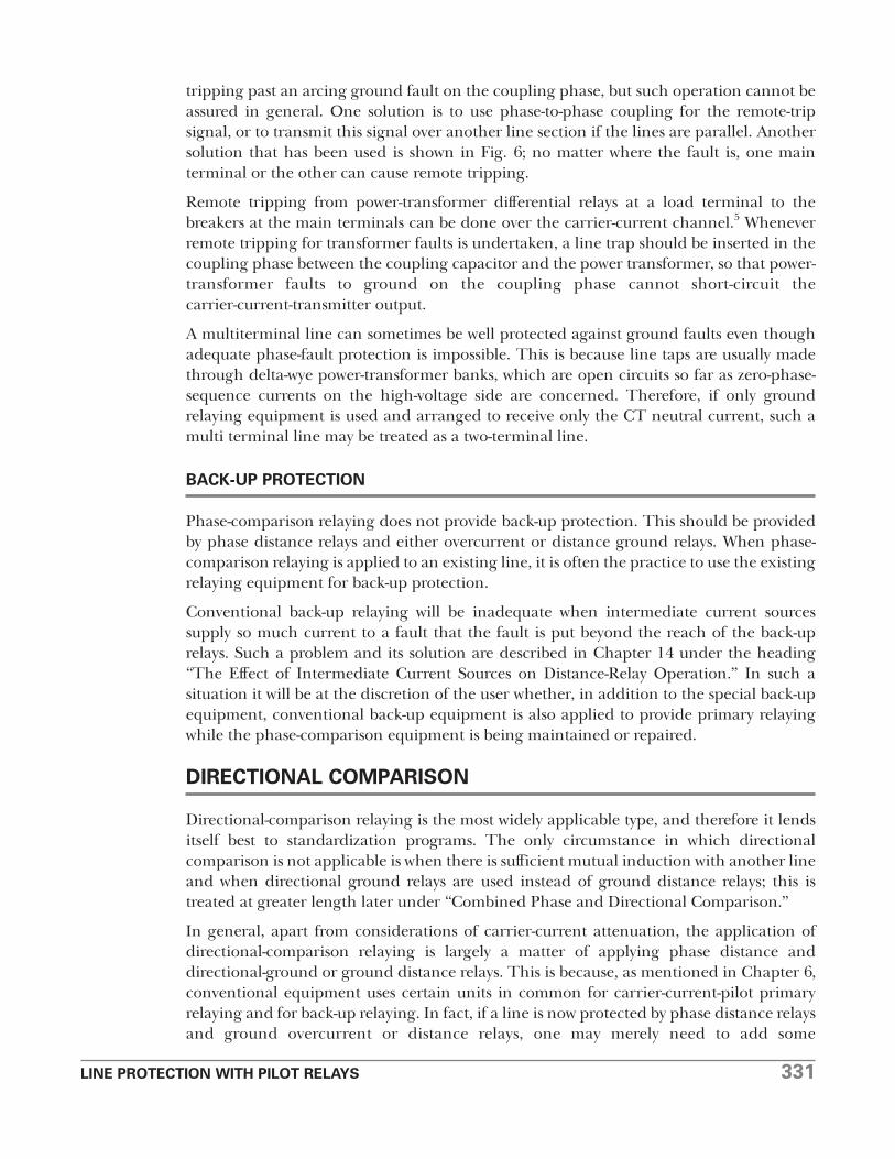
tripping past an arcing ground fault on the coupling phase, but such operation cannot beassured in general. One solution is to use phase-to-phase coupling for the remote-tripsignal, or to transmit this signal over another line section if the lines are parallel. Anothersolution that has been used is shown in Fig. 6; no matter where the fault is, one mainterminal or the other can cause remote tripping.
Remote tripping from power-transformer differential relays at a load terminal to thebreakers at the main terminals can be done over the carrier-current channel.5 Wheneverremote tripping for transformer faults is undertaken, a line trap should be inserted in thecoupling phase between the coupling capacitor and the power transformer, so that power-transformer faults to ground on the coupling phase cannot short-circuit thecarrier-current-transmitter output.
A multiterminal line can sometimes be well protected against ground faults even thoughadequate phase-fault protection is impossible. This is because line taps are usually madethrough delta-wye power-transformer banks, which are open circuits so far as zero-phase-sequence currents on the high-voltage side are concerned. Therefore, if only groundrelaying equipment is used and arranged to receive only the CT neutral current, such amulti terminal line may be treated as a two-terminal line.
BACK-UP PROTECTION
Phase-comparison relaying does not provide back-up protection. This should be providedby phase distance relays and either overcurrent or distance ground relays. When phase-comparison relaying is applied to an existing line, it is often the practice to use the existingrelaying equipment for back-up protection.
Conventional back-up relaying will be inadequate when intermediate current sourcessupply so much current to a fault that the fault is put beyond the reach of the back-uprelays. Such a problem and its solution are described in Chapter 14 under the heading“The Effect of Intermediate Current Sources on Distance-Relay Operation.” In such asituation it will be at the discretion of the user whether, in addition to the special back-upequipment, conventional back-up equipment is also applied to provide primary relayingwhile the phase-comparison equipment is being maintained or repaired.
DIRECTIONAL COMPARISON
Directional-comparison relaying is the most widely applicable type, and therefore it lendsitself best to standardization programs. The only circumstance in which directionalcomparison is not applicable is when there is sufficient mutual induction with another lineand when directional ground relays are used instead of ground distance relays; this istreated at greater length later under “Combined Phase and Directional Comparison.”
In general, apart from considerations of carrier-current attenuation, the application ofdirectional-comparison relaying is largely a matter of applying phase distance anddirectional-ground or ground distance relays. This is because, as mentioned in Chapter 6,conventional equipment uses certain units in common for carrier-current-pilot primaryrelaying and for back-up relaying. In fact, if a line is now protected by phase distance relaysand ground overcurrent or distance relays, one may merely need to add some

332 LINE PROTECTION WITH PILOT RELAYS
supplementary relays plus the carrier-current equipment to apply directional-comparisoncarrier-current-pilot relaying; the supplementary relays and carrier-current equipmentprovide the blocking function while the existing relays provide the tripping function. Ofcourse, completely separate relaying could be used, but it would be more expensive.
RELATION BETWEEN SENSITIVITIES OF TRIPPING ANDBLOCKING UNITS FOR TWO-TERMINAL LINES
The principal application procedure is to be sure that the correct relations are obtainedbetween the operating ranges of the blocking and tripping units. This is seldom a problemfor a two-terminal line. Figure 7 shows the relative operating ranges of the blocking andtripping units at both ends of a two-terminal line for, say, phase faults. The significantobservation is that, for external faults beyond either end of the line, the blocking unitsmust reach out farther than the tripping units to be certain that, if there is any tendencyto trip, it will surely be blocked. The tripping range for phase faults will be the operatingrange of the second- or third-zone distance-relay units, depending on the type ofequipment.
The only time there is any problem adjusting the blocking units is when their range has tobe so great that they might operate on load current, or that having operated for a fault theymight not reset on load current. In such situations, it becomes necessary to use additionalunits called “blinders.” These units are angle-impedance distance-relay units, one of whichwould be used with each blocking relay. The contacts of the two relays of each group would
be connected in parallel so that both would have to open to start carrier. Figure 8 showsthe operating characteristics of both relays and the point representing the load conditionthat makes blinders necessary. The resulting blocking region is shown cross-hatched.Blinders with impedance-type distance relays are shown because this type of relay is themost likely to require blinders for this purpose.
Incidentally, such blinders have been used also to prevent tripping on load current wheredistance relays have been applied to unusually long lines.
When low-tension voltage is used, transformer-drop compensation is not so necessary aswhen distance relays are used alone. The only time that transformer-drop compensationwould be beneficial would be when the carrier-current equipment is out of service andcomplete reliance for protection is being placed on the distance relays. Such circumstancesoccupy so little of the total time that the additional complications of transformer-dropcompensation are not justified.
Fig. 7. Relative operating ranges of directional-comparison blocking and tripping units.

LINE PROTECTION WITH PILOT RELAYS 333
The problem of obtaining the correct relations between the tripping and blocking units formultiterminal-line applications, along with other related problems, is treated next.
THE PROTECTION OF MULTITERMINAL LINES
Directional-comparison relaying is applicable to any multiterminal line. However, undersome circumstances proper operation will not be obtained without a very careful choice ofthe type of equipment and of the blocking- and tripping-relay adjustments.4,15 Andsometimes simultaneous high-speed tripping at all terminals will not be obtained.Therefore, one should be familiar with these circumstances so as to be able to avoid them,ifpossible,intheearly stagesof system planning. These circumstances will now be described.
Current Flow Out of One Terminal for an Internal Fault. In Fig. 9, directional-comparisonrelaying cannot trip for an internal fault if the current flowing out of the line at A is higherthan the blocking-relay pickup there. This situation may exist for phase faults or groundfaults or both. If it is not permissible to raise the blocking relay pickup so as to avoid thissituation, tripping must wait until the back-up relays at B trip their breaker, after whichhigh-speed tripping can occur at the other two terminals.. For phase faults, the distancerelays at B will operate at high speed, and sequential high-speed tripping of all otherterminals can follow if there is enough fault current, and if other features of the equipmentdo not introduce time delay. For ground faults, the tripping of breaker B will be delayedslightly unless ground distance or instantaneous overcurrent ground relays are used.
Remote tripping from breaker B to the other terminals by means of carrier current overthe protected line is not a reliable way to avoid sequential tripping, unless this type ofdifficulty occurs only for faults not involving ground. Or, if it occurs only for ground faults,phase-to-phase coupling could be used. Although some users are relying on gettingsufficient remote-tripping signal past a phase-to-ground fault on the coupling phase,satisfactory results cannot be assured in general. Occasionally, another line section can beused for carrying the remote-tripping signal. Obviously, remote tripping would be practicalif microwave were used instead of carrier current.
Fig. 8. A blinder to prevent blocking on load current.
334 LINE PROTECTION WITH PILOT RELAYS
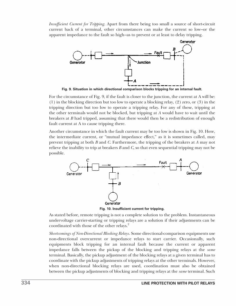
Insufficient Current for Tripping. Apart from there being too small a source of short-circuitcurrent back of a terminal, other circumstances can make the current so low–or theapparent impedance to the fault so high–as to prevent or at least to delay tripping.
For the circumstance of Fig. 9, if the fault is closer to the junction, the current at A will be:(1) in the blocking direction but too low to operate a blocking relay, (2) zero, or (3) in thetripping direction but too low to operate a tripping relay. For any of these, tripping atthe other terminals would not be blocked, but tripping at A would have to wait until thebreakers at B had tripped, assuming that there would then be a redistribution of enoughfault current at A to cause tripping there.
Another circumstance in which the fault current may be too low is shown in Fig. 10. Here,the intermediate current, or “mutual impedance effect,” as it is sometimes called, mayprevent tripping at both B and C. Furthermore, the tripping of the breakers at A may notrelieve the inability to trip at breakers B and C, so that even sequential tripping may not bepossible.
As stated before, remote tripping is not a complete solution to the problem. Instantaneousundervoltage carrier-starting or tripping relays are a solution if their adjustments can becoordinated with those of the other relays.2
Shortcomings of Non-Directional Blocking Relays. Some directional-comparison equipments usenon-directional overcurrent or impedance relays to start carrier. Occasionally, suchequipments block tripping for an internal fault because the current or apparentimpedance falls between the pickup of the blocking and tripping relays at the sameterminal. Basically, the pickup adjustment of the blocking relays at a given terminal has tocoordinate with the pickup adjustments of tripping relays at the other terminals. However,when non-directional blocking relays are used, coordination must also be obtainedbetween the pickup adjustments of blocking and tripping relays at the same terminal. Such
Fig. 9. Situation in which directional comparison blocks tripping for an internal fault.
Fig. 10. Insufficient current for tripping.

LINE PROTECTION WITH PILOT RELAYS 335
a circumstance can exist when there is insufficient current or too high an apparentimpedance to cause tripping at a given terminal until after another terminal has tripped,as in one of the preceding cases. However, if a blocking relay at the given terminal shouldoperate, it would block tripping at the other terminals; this situation would persist until aback-up relay operated to cause tripping at another terminal that would permit the giventripping relay to operate. The best solution to this problem is directional blocking relays.
Miscellaneous Problems of Coordinating Blocking and Tripping Sensitivities. It is necessary thatthe coordination between blocking and tripping sensitivities be carefully analyzed not onlyfor multiterminal operation but also when a line is operated with one or more terminalsopen. Owing to elimination of intermediate current sources, such operation may increasethe reach of the tripping relays at one terminal; one must be sure that these relays do notoutreach the blocking relays at another terminal.
Figures 11 and 12 show two extreme operating conditions for a three-terminal line, so faras the relative blocking and tripping sensitivities are concerned. For Fig. 11, the blockingrelays at terminal B get twice as much current as the tripping relays at A or C; for Fig 12,the blocking relays at B and C get only half as much current as the tripping relays at A.Even greater extremes could exist for a line with more than three terminals.
Need for a Blinder on the Loss-of-Synchronism Blocking Relay. If the phase tripping relays atterminal A of Fig. 13 cannot operate to trip until after terminal B has tripped for the faultlocation P, a supplementary angle-impedance relay should be used to provide a “blinder”for the loss-of-synchronism blocking relay. The need for this blinder is shown in Fig. 14.The point P1 represents the way the fault first appears to the tripping and blocking relaysat A, and the point P2 represents the appearance of the fault after B has tripped.
Fig. 11. Directional-comparison blocking relays get twice as much current as tripping relays.
Fig. 12. Directional-comparison tripping relays get twice as much current as blocking relays.

336 LINE PROTECTION WITH PILOT RELAYS
It will be noted that this sequence will establish local blocking at A by the loss-of-synchronism relay, and, consequently, that tripping there can only occur in third-zonetime.
Figure 14 shows how the blinder characteristic modifies the operating characteristic of theblocking relay so that when the fault first occurs it will not fulfill the requirement for thesecond step in the sequence of operations necessary to set up loss-of-synchronism blocking.The effective blocking area is shown cross-hatched.
Blocking-Terminal Equipment at Load Terminals. At terminals behind which there is no sourceof generation, only blocking equipment may be required. Such equipment is required ifthe high-speed relays at any of the main terminals are sensitive enough to operate for alow-voltage fault at such a load terminal. The blocking-terminal equipment consists ofinstantaneous overcurrent relays, energized from CT’s on the high-voltage side of thepower-transformer bank, and carrier-current transmitting and receiving equipment. Theovercurrent relays start the transmission of carrier current to block tripping at the mainterminals for low-voltage faults at the load terminal or for magnetizing-current inrush tothe load-terminal power-transformer bank.
Fig. 13. Situation in which the loss-of-synchronism blocking relay will block trippingfor an internal fault.
Fig. 14. R-X diagram of the conditions of Fig. 13.

LINE PROTECTION WITH PILOT RELAYS 337
As described for phase-comparison relaying, remote tripping from a blocking-terminalpower-transformer differential relay to the breakers at the main terminals can beaccomplished over the carrier-current channel.5
EFFECT OF TRANSIENTS
Directional-comparison relaying using high-speed ground relays energized from zero-phase-sequence quantities is exposed to more possibilities of misoperation than isphase-comparison relaying. Reference 6 describes a host of things that tend to fool suchground relays. However, conventional directional-comparison-relaying equipments havecertain features, developed as a result of experience, that minimize any tendency towardmisoperation. Such features are: (1) limited sensitivity, (2) slight time delay in auxiliaryrelays, and (3) “transient blocking” or the prolongation of a carrier-current blocking signalfor several cycles after a relay operates to try to shut it off. Also, induction-type directionalunits in both the carrier-starting and the tripping functions make the units unresponsiveto transients in only one of the operating quantities.
Ground distance relays, that respond to positive-phase-sequence impedance, forcontrolling carrier-current transmission and for tripping eliminate the problem ofmisoperation on transients.
COMBINED PHASE AND DIRECTIONAL COMPARISON
Directional-comparison relaying using directional-ground relays may operate undesirablyif there is sufficient mutual induction with a neighboring power circuit.6 The directional-ground relays misoperate because their polarization is adversely affected, as will bedescribed later. This would seem to indicate the desirability of phase-comparison relayingwhich would be unaffected by mutual induction. If phase comparison was completelyapplicable, it would be a good solution. However, occasionally it does not have sufficientsensitivity for phase faults, although it would be entirely satisfactory for ground faults.Under these circumstances combined phase- and directional-comparison relaying ischosen. The directional-comparison principle is used for phase faults and the phase-comparison principle is used for ground faults. Because the carrier-current transmitterand receiver are employed in common, the equipment is only a little more expensive thandirectional comparison alone. Incidentally, the phase-comparison ground-fault equipmentis less affected by most of the transient conditions that affect directional-ground relays.
Fig. 15. Illustrating the cause of undesired directional-ground-relay operationresulting from mutual induction.
338 LINE PROTECTION WITH PILOT RELAYS
If ground distance relays were used in the directional-comparison equipment instead ofdirectional-ground relays, it would be unnecessary to resort to combined phase- anddirectional-comparison equipment. However, it would be somewhat more expensive, but itwould provide better back-up protection.
THE EFFECT OF MUTUAL INDUCTION ONDIRECTIONAL-GROUND RELAYS
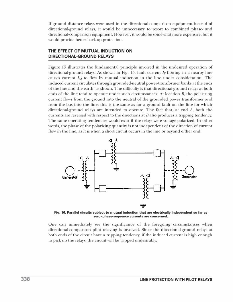
Figure 15 illustrates the fundamental principle involved in the undesired operation ofdirectional-ground relays. As shown in Fig. 15, fault current IF flowing in a nearby linecauses current IM to flow by mutual induction in the line under consideration. Theinduced current circulates through grounded-neutral power-transformer banks at the endsof the line and the earth, as shown. The difficulty is that directional-ground relays at bothends of the line tend to operate under such circumstances. At location B, the polarizingcurrent flows from the ground into the neutral of the grounded power transformer andfrom the bus into the line; this is the same as for a ground fault on the line for whichdirectional-ground relays are intended to operate. The fact that, at end A, both thecurrents are reversed with respect to the directions at B also produces a tripping tendency.The same operating tendencies would exist if the relays were voltage-polarized. In otherwords, the phase of the polarizing quantity is not independent of the direction of currentflow in the line, as it is when a short circuit occurs in the line or beyond either end.
One can immediately see the significance of the foregoing circumstances whendirectional-comparison pilot relaying is involved. Since the directional-ground relays atboth ends of the circuit have a tripping tendency, if the induced current is high enoughto pick up the relays, the circuit will be tripped undesirably.
Fig. 16. Parallel circuits subject to mutual induction that are electrically independent so far aszero~phase-sequence currents are concerned.

LINE PROTECTION WITH PILOT RELAYS 339
The conditions of Fig. 15 are extreme in view of the fact that the line section in whichinduced current flows cannot directly contribute short-circuit current to the other circuit.However, it is not an impossible situation. It can exist whenever electrically independentcircuits are closely paralleled, or in a case such as that illustrated in Fig. 16. Although thesetwo circuits are paralleled at their ends, they are independent so far as zero-phase-sequencecurrents are concerned.
Situations that are more apt to be encountered are illustrated in Fig. 17. It is only necessaryin either case of Fig. 17 that the breaker of the faulty line be open at the end where thelines are normally paralleled, in order to have the condition that can produce anundesirable tripping tendency of the directional-ground relays of the sound line. Thisbreaker may be open either because it was tripped by its protective relays immediately whenthe fault occurred and before the breaker at the other end could trip, or because the linehad been open at both ends and the breaker at the other end was reclosed first on apersisting fault. Not only would the directional elements at both ends of the sound linepermit tripping, but the current magnitudes may be large enough so that selectivity wouldnot be obtained.
Sometimes it is even unnecessary that the breaker in the faulty line of Fig. 17 be open. Ifthe effect of mutual induction is great enough, it can overcome the tendency of theunfaulted line to supply current to the fault, and actually reverse the direction of itscurrent.
Fig. 17. Situations in which lines are directly paralleled at one end only.
340 LINE PROTECTION WITH PILOT RELAYS
Apart from phase-comparison relaying or directional ground distance relays, othersolutions to the problem can sometimes be found. The zero-phase-sequence current orvoltage at the ends of the faulted circuit may be enough greater than at the correspondingends of the unfaulted circuit so that a relay can be interposed that balances thecorresponding quantities and permits only the circuit to trip that has the larger quantity.Another possible solution is to parallel the CT’s in the neutrals of the power transformers,as, for example, at X and Y of Fig, 17, and to use the resulting current to polarize thedirectional� relays of both lines at that end. At the other end of the circuits of Fig. 17, a CTin the neutral of the one power-transformer bank shown at Z would suffice for thedirectional-ground relays of both lines; or voltage polarization might be used at this end.
Should the line terminals be too far apart at one end, as when two lines run close to oneanother for part of their length and then diverge, it would be impossible to employ thealternatives to phase-comparison relaying that have been described. One remainingalternative would be to determine if the magnitude of the zero-phase-sequence current orvoltage at the ends of the lines could not be used alone to permit operation, subject todirectional control, only if the magnitude was high enough. Another possibility is to takeadvantage of the fact that the phase-to-neutral voltages of the circuit in which the inducedcurrent flows are usually not as low during the induced-current condition as they are whilea ground fault exists on the line itself.
It was mentioned in Chapter 13 that a negative-phase-sequence directional-ground relaywould not be affected by mutual induction. However, such a relay has other disadvantages,as mentioned also, that make it desirable to seek some other alternative.
ALL-ELECTRONIC DIRECTIONAL-COMPARISON EQUIPMENT
All-electronic directional-comparison equipment, including electronic phase distance anddirectional-ground relays, has been in service since 1953.16 The average operating time ofthis equipment is 5/8 cycle with a maximum of 1.0 cycle, as compared with 1.0 to 3.0 cyclesfor conventional electromechanical relay equipment.
Such operating speeds eventually become necessary, not only to maintain stability whenfaults occur but also to minimize the damage from ever-increasing concentrations of short-circuit current.
The application procedures and problems are the same as those described for theelectromechanical equipment.
MICROWAVE
A microwave pilot is used for relaying only when the relaying equipment can share thechannel with enough other services; it is not economically justifiable for relaying alone ifcarrier current or wire pilot is applicable.l7
Microwave is entirely suitable although it is not as reliable as carrier current for protective-relaying purposes; this is partly because of the complex circuitry and the large number oftubes involved, and also because of the large number of services on the same microwavechannel. When repeater stations are necessary, the complexity practically doubles withfurther loss of reliability. Of course, one realize that the requirements of protective relaying

LINE PROTECTION WITH PILOT RELAYS 341
as to reliability are in certain respects more severe than the requirements of other servicesthat use the microwave channel. Any lapse in the signal when a fault occurs isunacceptable.
Microwave has certain theoretical advantages over carrier current because it is dissociatedfrom the power line,18 but its only real advantage is in connection with remote tripping,which will be considered later. Occasionally, microwave is useful where the attenuationwould be too high for carrier current, such as on a power-cable circuit, but even theremicrowave would probably not be selected unless there were many other uses in additionto protective relaying.
The same relaying equipments that are used with a carrier-current pilot are also used witha microwave pilot. Therefore, the application considerations are the same so far as therelaying equipment is concerned.
THE MICROWAVE CHANNEL
The microwave channel is a line-of-sight-radio system operating on a frequency band inthe United States assigned by the Federal Communications Commission in the range from950 to 30,000 megacycles.19 Such a system requires that a straight line from one antenna toanother be above intervening objects, preferably by about 50 feet. This usually limits thedistance between antennae to about 20 to 50 miles, depending on the topography of theland. Where a longer channel is required, one or more “repeater stations” may benecessary. One repeater station doubles the base channel equipment, except that only oneadditional tower is necessary; hence, the cost of a microwave channel is dependent on itslength.
It is the practice to use standby equipment automatically switched into service in the eventthat the regular equipment fails.
For protective relaying that cannot tolerate even a moment’s outage when a fault occurs,operation from a power-system a-c source is not acceptable. It is necessary to providean a-c generator operating from the station battery, or d-c-operated equipment. Thisbecomes more of a problem at a repeater station where a suitable battery source would nototherwise be available.
For protective-relaying purposes, the practice is to modulate the microwave frequencydirectly by any of the usual methods, such as, for example, by a so-called “tone.” Such atone is a single-frequency voltage in the audio range or above. Tones above the audiorange are preferred because the time constants of their filter circuits are shorter, andtherefore it is unnecessary to delay tripping to allow time for the receiver output to buildup sufficiently to block tripping.
REMOTE TRIPPING
The principal advantage of microwave for protective relaying is that the presence of a faulton the protected line will not interfere with the transmission of a remote-tripping signal.For the protection of three-terminal lines, there are circumstances when the relays at agiven terminal cannot operate to trip their breakers until after the breakers trip at anotherterminal. With microwave, the first relays to operate can cause the transmission of a
342 LINE PROTECTION WITH PILOT RELAYS
tripping signal to another terminal and thereby eliminate part of the time delay in thesequential tripping of this other terminal.20
This ability to perform remote tripping without hindrance by a fault makes possible theuse of a different principle for line protection.18 To apply this principle, it is first necessarythat the high zones of the relays at all terminals overlap for all types of fault in such a waythat, for any fault, the relays of at least one terminal will always operate at high speed.Then, if each terminal is arranged to transmit a trip signal to each other terminal,practically simultaneous high-speed tripping will occur at all terminals; the remotetripping will be delayed about 2 to 3 cycles. Of course, each terminal is still free to trip athigh speed independently of the remote-tripping equipment whenever a fault occurswithin that terminal’s high-speed-tripping zone. This principle eliminates the need forblocking relays, as required by directional comparison, but it often requires distance relaysfor phase- and ground-fault protection. Where remote tripping is required for multiterminal applications, this type of relaying would have its greatest application; otherwise,the added time delay for certain faults would discourage its general usage wheresimultaneous high-speed tripping is possible with directional comparison.
Incidentally, the foregoing principle can be applied to a wire-pilot system by the use oftones.
HIGH-SPEED RECLOSING
High-speed automatic reclosing of transmission-line breakers after they have tripped toclear a fault is generally possible only with pilot relaying, because only pilot relaying is ableto cause all line terminals to trip at high speed and practically simultaneously. With suchhigh-speed tripping and reclosing, generators do not have time to swing very far out ofphase, and therefore no synchronism check is necessary before reclosing. The experiencewith such high-speed reclosing (or “ultra-high-speed reclosing,” as it is sometimes called)has been excellent,2 1
Generally, all three phases are tripped and reclosed for any kind of fault. Infrequently,however, such three-phase switching cannot be used, but it is possible to use single-phaseswitching to advantage.22 Such a possibility exists when there is only one line connecting ahydroelectric generating station to its system. If about 25% or more of the load on thegenerating station is dropped when a line is tripped, the generators will speed up toorapidly to permit high-speed reclosing. But for single-phase-to-ground faults, if only thefaulty phase is tripped and reclosed, stability can often be maintained; for any other kindof fault, all three phases are tripped but are not reclosed. Single-phase switching can beperformed with conventional relaying equipment by the addition of “phase-selector”relays.23
High-speed reclosing is permitted only when high-speed tripping is caused by theoperation of the pilot equipment or the first-zone units of distance relays. When trippingis caused by any other units, automatic reclosing is blocked until released locally by anoperator or remotely by supervisory control.

LINE PROTECTION WITH PILOT RELAYS 343
BIBLIOGRAPHY
1. “All-Electronic Carrier Relaying Reduces Fault-Clearing Time,” by H. C. Barnes andL. F. Kennedy, AIEE Trans., 73, Part III-A (1954), pp. 170-173. Discussions, p. 173.
2. “Line and Transformer Bank Relaying,” by J. L. Blackburn and G. D. Rockefeller, AIEETrans., 74, Part III (1955), pp. 334-339. Discussions, pp. 339-343.
“Unique Protection Required for Midwest Interconnection,” by A. J. Nicholson, Elec. Lightand Power, Nov., 1950, pp. 90-96.
3. “Pilot-Wire Circuits for Protective Relaying–Experience and Practice, 1942-1950,” byAIEE Committee, AIEE Trans., 72, Part III (1953), pp. 331-336. Discussions, p. 336.
4. “Relay Protection of Tapped Transmission Lines,” by M. A. Bostwick and E. L. Harder,AIEE Trans., 62 (1943), pp. 645-650. Discussions, pp. 969-972.
5. “Remote Tripping Schemes,” by AIEE Committee, AlEE Trans., 72, Part III (1953),pp. 142-150. Discussions, pp. 150-151.
“Protection of Stations without High-Voltage Switching,” by AIEE Committee, AIEE Trans.,68, Part I (1949), pp. 226-231. Discussions, pp. 231-232.
6. “Some Utility Ground-Relay Problems,” by H. C. Barnes and A. J. McConnell, AIEETrans., 74, Part III (1955), pp. 417-428. Discussions, pp. 428-433.
7. “Experience and Reliability of Carrier-Relaying Channels,” by AIEE Committee, AIEETrans., 72, Part III (1953), pp. 1223-1226. Discussions, p. 1227.
8. “Transmission Considerations in the Coordination of a Power Line Carrier Network,” byG. E. Burridge and A. S. C. Jong, AIEE Trans., 70, Part II ((1951), pp. 1335-40. Discussions,p. 1340.
“Applying Carrier Current to Power Lines,” by H. J. Sutton, Elec. World, 136 (Oct. 8, 1951),pp. 121-123.
“Propagation Characteristics of Power Line Carrier Links,” Brown Boveri Rev., 35(Sept./Oct., 1948), pp. 266-275.
“Operation of Power Line Carrier Channels,” by H. W. Lensner, AIEE Trans., 66 (1947),pp. 888-893. Discussions, pp. 893-894.
9. “Application of Carrier to Power Lines,” by F. M. Rives, AIEE Trans., 62 (1943), pp. 835-844. Discussions, pp. 945-947.
10. “Measurement of Carrier Circuit Impedances,” by W. H. Blankmeyer, Elec. World, 126(August 3, 1946), pp. 49-51.
“Report on Method of Measurements at Carrier Current Frequencies,” by AIEECommittee, AIEE Trans., 67, Part II (1948), pp. 1429-1432. Discussions, p. 1432.
“A Method of Measurement of Carrier Characteristics on Power Cables,” by B. J. Sparlinand J. D. Moynihan, AIEE Trans., 74, Part III, pp. 31-33.
11. “Loss Measurements Made on Underground-Cable Overhead-Conductor 132-KvTransmission Line at Carrier Current Frequencies,” by H. A. Cornelius and B. WadeStorer, AIEE Trans., 68, Part I (1949), pp. 597-601.
344 LINE PROTECTION WITH PILOT RELAYS
“Power Line Carrier Used on 110-Kv Cable,” by R. H. Miller, Elec. World, November 5,1949, p. 67.
12. “Sleet-Thawing Practices of the New England Electric System,” by C. P. Corey, H. R.Selfridge, and H. R. Tomlinson, AIEE Trans., 71, Part III (1952), pp. 649-657. Discussions,p. 657.
“Sleet Melting on the American Gas and Electric System,” by S. C. Bartlett, C. A. Imburgia,and G. H. McDaniel, AIEE Trans., 71, Part III (1952), pp. 704-708. Discussions, pp. 708 709.
“Forty-Two Years’ Experience Combating Sleet Accumulations,” by A. N. Shealy, K. L.Althouse, and R. N. Youtz, AIEE Trans., 71, Part III (1952), pp. 621-628.
“Ice-Melting and Prevention Practices on Transmission Lines,” by V. L. Davies and L. C.St. Pierre, AIEE Trans., 71, Part III (1952), pp. 593-597.
“Sleet-Melting Practices–Niagara Mohawk System,” by H. B. Smith and W. D. Wilder, AIEETrans., 71, Part III (1952), pp. 631-634.
“Carrier Attenuation Discloses Glaze Formation,” by G. G. Langdon and V. M. Marquis,Elec. World, 112 (August 12, 1939), pp. 38-40, 100-101.
13. “Considerations in Selecting a Carrier Relaying System,” by R. C. Cheek and J. L.Blackburn, AIEE Trans., 71, Part III (1952), pp. 10-15. Discussions, pp. 15-18.
14. “Phase-Comparison Carrier Relaying for 3-Terminal Lines,” by H. W. Lensner, AIEETrans., 72, Part III (1953), pp. 697-701. Discussions, pp. 701-702.
15. “Power-Line Carrier for Relaying and Joint Usage–Part II,” by G. W. Hampe andB. Wade Storer, AIEE Trans., 71, Part III (1952), pp. 661-668. Discussions, pp. 668-670.
“Relaying of Three-Terminal Lines,” by C. W. Cogburn, Elec. Light and Power, March, 1954,pp. 71-73.
16. “All-Electronic 1-Cycle Carrier Relaying Equipment–Relay Operating Principles,” byM. E. Hodges and R. E. Macpherson, AIEE Trans., 73, Part III-A (1954), pp. 174-186.
“An All-Electronic 1-Cycle Carrier-Relaying System–Over-All Operating Principles,” byH. T. Seeley and N. A. Koss, AIEE Trans., 73, Part III-A (1954), pp. 161-168. Discussions,pp. 168-169.
“Performance Evaluation of All-Electronic 1-Cycle Carrier-Relaying Equipment,” by W. S.Price, R. E. Cordray, and R. H. Macpherson, AIEE Trans., 73, Part III-A, pp. 187-192.Discussions, pp. 192-195.
17. “Economics of Relaying by Microwave,” by R. C. Cheek, Elec. Light and Power, May, 1951,pp. 82-84.
18. “Protective Relaying over Microwave Channels,” by H. W. Lensner, AIEE Trans., 71,Part III (1952), pp. 240-244. Discussions, pp. 244-245.
19. “Microwave Channels for Power System Applications,” by AIEE Committee, AIEETrans., 68, Part I (1949), pp. 40-42. Discussions, pp. 42-43.
20. “Power System Stability Criteria for Design,” by W. A. Morgan, AIEE Trans., 71, Part III(1952), pp. 499-503. Discussions, pp. 503-504.
LINE PROTECTION WITH PILOT RELAYS 345
21. “Five Years Experience with Ultra-High-Speed Reclosing of High-Voltage TransmissionLines,” by Philip Sporn and C. A. Muller, AIEE Trans., 60 (1941), pp. 241-246. Discussions,p. 690.
22. Power System Stability–Vol. II, by S. B. Crary, John Wiley & Sons, New York, 1947.
23. “Relays and Breakers for High-Speed Single-Pole Tripping and Reclosing,” by S. L.Goldsborough and A. W. Hill, AIEE Trans., 61 (1942), pp. 77-81. Discussions, p. 429.
REVIEW PROBLEMS
1. A system short-circuit study is to be made. What quantities should be obtained forstudying the application of protective relays? What other data are required to apply(a) overcurrent relays, (b) pilot relays, and (c) distance relays?
2. Name and describe briefly the various methods for obtaining selectivity.
3. Discuss the factors governing the choice of transmission-line-relaying equipment. Whichtype would lend itself best to standardization, and why?
4. Given a breaker with 1200/5 bushing CT’s having the secondary-excitationcharacteristic of Fig. 3 of Chapter 7. What would the ASA accuracy classification be for the40-turn tap (ratio 200/5)? Assume the tap winding to be fully distributed..
5. On what basis is it permissible to superimpose system and relay characteristics on thesame R-X diagram for the purpose of studying relay response?
6. Under what circumstance is distance relaying affected by short-circuit-currentmagnitude?
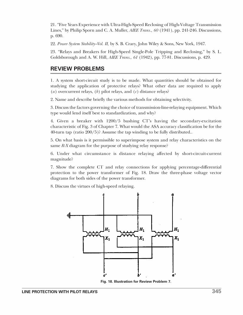
7. Show the complete CT and relay connections for applying percentage-differentialprotection to the power transformer of Fig. 18. Draw the three-phase voltage vectordiagrams for both sides of the power transformer.
8. Discuss the virtues of high-speed relaying.
Fig. 18. Illustration for Review Problem 7.

346 LINE PROTECTION WITH PILOT RELAYS
9. Write “true” or “false” after each of the following:
(a) Overcurrent relays with more-inverse curves are better to use when the generatingcapacity changes more from time to time.
(b) Instantaneous overcurrent relays are more applicable on the longer lines.
(c) Mho-type distance relays are more 1ikely to operate undesirably on power swings thanother types of distance relays.
(d) Any distance relay–no matter where it is located–will trip on loss of synchronism.
(e) Sensitive, high-speed bus protection can always be obtained with differentiallyconnected overcurrent relays.
(f) In attended stations, it is not the practice to let transformer overload relays trip thetransformer breakers.
(g) Back-up relaying is not a substitute for good maintenance.