1514.8 05 en
TRANSCRIPT

In-line Pump
Etaline L
Installation/Operating Manual

Legal information/Copyright
Installation/Operating Manual Etaline L
Original operating manual
All rights reserved. The contents provided herein must neither be distributed, copied, reproduced,edited or processed for any other purpose, nor otherwise transmitted, published or made available to athird party without the manufacturer's express written consent.
Subject to technical modification without prior notice.
© KSB SE & Co. KGaA, Frankenthal 22/04/2020

Contents
3 of 60Etaline L
Contents
Glossary .................................................................................................................................................. 5
1 General.................................................................................................................................................... 61.1 Principles ........................................................................................................................................................... 61.2 Installation of partly completed machinery.................................................................................................... 61.3 Target group..................................................................................................................................................... 61.4 Other applicable documents............................................................................................................................ 61.5 Symbols ............................................................................................................................................................. 61.6 Key to safety symbols/markings....................................................................................................................... 7
2 Safety...................................................................................................................................................... 82.1 General.............................................................................................................................................................. 82.2 Intended use ..................................................................................................................................................... 82.3 Personnel qualification and training............................................................................................................... 92.4 Consequences and risks caused by non-compliance with this manual ......................................................... 92.5 Safety awareness .............................................................................................................................................. 92.6 Safety information for the operator/user ....................................................................................................... 92.7 Safety information for maintenance, inspection and installation .............................................................. 102.8 Unauthorised modes of operation................................................................................................................ 102.9 Electromagnetic compatibility....................................................................................................................... 10
3 Transport/Storage/Disposal ................................................................................................................ 113.1 Checking the condition upon delivery .......................................................................................................... 113.2 Transport......................................................................................................................................................... 113.3 Storage/preservation...................................................................................................................................... 113.4 Return to supplier........................................................................................................................................... 123.5 Disposal ........................................................................................................................................................... 12
4 Description of the Pump (Set) ............................................................................................................. 144.1 General description ........................................................................................................................................ 144.2 Product information....................................................................................................................................... 14
4.2.1 Product Information as per Regulation No. 547/2012 (for water pumps with a maximum shaftpower of 150 kW) implementing "Ecodesign" Directive 2009/125/EC........................................... 14
4.2.2 Product information as per Regulation No. 1907/2006 (REACH) .................................................... 144.3 Designation..................................................................................................................................................... 154.4 Name plate...................................................................................................................................................... 164.5 Design details.................................................................................................................................................. 164.6 Configuration and function........................................................................................................................... 174.7 Noise characteristics ....................................................................................................................................... 184.8 Scope of supply............................................................................................................................................... 184.9 Dimensions and weight.................................................................................................................................. 18
5 Installation at Site ................................................................................................................................ 195.1 Safety regulations........................................................................................................................................... 195.2 Checks to be carried out prior to installation............................................................................................... 195.3 Installing the pump set .................................................................................................................................. 205.4 Piping .............................................................................................................................................................. 20
5.4.1 Connecting the piping....................................................................................................................... 205.4.2 Permissible forces and moments at the pump nozzles.................................................................... 225.4.3 Vacuum balance line.......................................................................................................................... 245.4.4 Auxiliary connections......................................................................................................................... 25
5.5 Enclosure/insulation ....................................................................................................................................... 255.6 Electrical connection ...................................................................................................................................... 26
5.6.1 Motor connection inside the terminal box ...................................................................................... 26
6 Commissioning/Start-up/Shutdown................................................................................................... 296.1 Commissioning/Start-up/Shutdown............................................................................................................... 29
6.1.1 Prerequisites for commissioning/start-up ......................................................................................... 29

Contents
4 of 60 Etaline L
6.1.2 Checking earth conductor connection ............................................................................................. 296.1.3 Checking insulation resistance .......................................................................................................... 296.1.4 Filling in lubricants............................................................................................................................. 306.1.5 Priming and venting the pump......................................................................................................... 306.1.6 Checking the direction of rotation ................................................................................................... 306.1.7 Start-up............................................................................................................................................... 316.1.8 Checking the shaft seal...................................................................................................................... 326.1.9 Shutdown ........................................................................................................................................... 32
6.2 Operating limits.............................................................................................................................................. 336.2.1 Ambient temperature........................................................................................................................ 336.2.2 Frequency of starts............................................................................................................................. 346.2.3 Fluid handled ..................................................................................................................................... 346.2.4 Voltages and frequencies .................................................................................................................. 356.2.5 Maximum permissible speed ............................................................................................................. 356.2.6 Altitude............................................................................................................................................... 35
6.3 Shutdown/storage/preservation .................................................................................................................... 356.3.1 Measures to be taken for shutdown ................................................................................................ 35
6.4 Returning to service ....................................................................................................................................... 36
7 Servicing/Maintenance........................................................................................................................ 377.1 Safety regulations........................................................................................................................................... 377.2 Servicing/Inspection........................................................................................................................................ 38
7.2.1 Supervision of operation ................................................................................................................... 387.2.2 Inspection work.................................................................................................................................. 407.2.3 Lubrication and lubricant change..................................................................................................... 40
7.3 Drainage/cleaning .......................................................................................................................................... 417.4 Dismantling the pump set.............................................................................................................................. 41
7.4.1 General information/Safety regulations........................................................................................... 417.4.2 Preparing the pump set..................................................................................................................... 427.4.3 Dismantling the complete pump set ................................................................................................ 427.4.4 Removing the back pull-out unit ...................................................................................................... 427.4.5 Removing the impeller ...................................................................................................................... 437.4.6 Removing the mechanical seal.......................................................................................................... 43
7.5 Reassembling the pump set ........................................................................................................................... 437.5.1 General information/Safety regulations........................................................................................... 437.5.2 Fitting the mechanical seal................................................................................................................ 447.5.3 Fitting the impeller ............................................................................................................................ 447.5.4 Installing the back pull-out unit ....................................................................................................... 45
7.6 Tightening torques......................................................................................................................................... 457.7 Spare parts stock............................................................................................................................................. 45
7.7.1 Ordering spare parts.......................................................................................................................... 457.7.2 Recommended spare parts stock for 2 years' operation to DIN 24296 .......................................... 46
8 Trouble-shooting.................................................................................................................................. 47
9 Related Documents .............................................................................................................................. 499.1 Installation types ............................................................................................................................................ 499.2 General assembly drawing with list of components .................................................................................... 51
10 EU Declaration of Conformity ............................................................................................................. 52
11 EU Declaration of Conformity ............................................................................................................. 53
12 EU Declaration of Conformity ............................................................................................................. 54
13 Certificate of Decontamination........................................................................................................... 55
Index ..................................................................................................................................................... 56

Glossary
5 of 60Etaline L
1514
.8/0
5-EN
Glossary
Back pull-out unitPump without pump casing; partly completedmachinery
Certificate of decontaminationA certificate of decontamination is enclosed by thecustomer when returning the product to themanufacturer to certify that the product has beenproperly drained to eliminate any environmentaland health hazards arising from components incontact with the fluid handled.
Close-coupled designMotor directly fitted to the pump via a flange or adrive lantern
Discharge lineThe pipeline which is connected to the dischargenozzle
Hydraulic systemThe part of the pump in which the kinetic energyis converted into pressure energy
IE3Efficiency class to IEC 60034-30: 3 = PremiumEfficiency (IE = International Efficiency)
In-line designA pump whose suction and discharge nozzle arearranged opposite each other and have the samenominal diameter.
PumpMachine without drive, additional components oraccessories
Pump setComplete pump set consisting of pump, drive,additional components and accessories
Suction lift line/suction head lineThe pipeline which is connected to the suctionnozzle
WRASApproved by all water suppliers in the UK (WRAS =Water Regulations Advisory Scheme)
1 General
6 of 60 Etaline L
1514
.8/0
5-EN
1 General
1.1 PrinciplesThis operating manual is valid for the type series and variants indicated on the frontcover.
The operating manual describes the proper and safe use of this equipment in allphases of operation.
The name plate indicates the type series, the main operating data and the materialnumber/series code. The material number/series code uniquely describes the productand is used as identification in all further business processes.
In the event of damage, immediately contact your nearest KSB service facility tomaintain the right to claim under warranty.
1.2 Installation of partly completed machineryTo install partly completed machinery supplied by KSB refer to the sub-sections underServicing/Maintenance.
1.3 Target groupThis operating manual is aimed at the target group of trained and qualified specialisttechnical personnel. (ð Section 2.3, Page 9)
1.4 Other applicable documents
Table 1: Overview of other applicable documents
Document Contents
Data sheet Description of the technical data of the pump (set)
General arrangement drawing/outline drawing
Description of mating dimensions and installationdimensions for the pump (set), weights
Drawing of auxiliary connections Description of auxiliary connections
Hydraulic characteristic curve Characteristic curves showing head, NPSHrequired, efficiency and power input
General assembly drawing1) Sectional drawing of the pump
Sub-supplier product literature1) Operating manuals and other product literaturedescribing accessories and integrated machinerycomponents
Spare parts lists1) Description of spare parts
Piping layout1) Description of auxiliary piping
List of components1) Description of all pump components
Assembly drawing1) Sectional drawing of the installed shaft seal
For accessories and/or integrated machinery components observe the relevantmanufacturer's product literature.
1.5 Symbols
Table 2: Symbols used in this manual
Symbol Description
✓ Conditions which need to be fulfilled before proceeding with thestep-by-step instructions
⊳ Safety instructions
⇨ Result of an action
⇨ Cross-references
1) If agreed to be included in the scope of supply
1 General
7 of 60Etaline L
1514
.8/0
5-EN
Symbol Description
1.
2.
Step-by-step instructions
NoteRecommendations and important information on how to handlethe product
1.6 Key to safety symbols/markings
Table 3: Definition of safety symbols/markings
Symbol Description
! DANGER DANGER This signal word indicates a high-risk hazard which, if not avoided,will result in death or serious injury.
! WARNING WARNING This signal word indicates a medium-risk hazard which, if notavoided, could result in death or serious injury.
CAUTION CAUTION This signal word indicates a hazard which, if not avoided, couldresult in damage to the machine and its functions.
General hazard In conjunction with one of the signal words this symbol indicates ahazard which will or could result in death or serious injury.
Electrical hazard In conjunction with one of the signal words this symbol indicates ahazard involving electrical voltage and identifies information aboutprotection against electrical voltage.
Machine damage In conjunction with the signal word CAUTION this symbol indicatesa hazard for the machine and its functions.

2 Safety
8 of 60 Etaline L
1514
.8/0
5-EN
2 Safety
! DANGER All the information contained in this section refers to hazardous situations.
In addition to the present general safety information the action-related safetyinformation given in the other sections must be observed.
2.1 General▪ This operating manual contains general installation, operating and maintenance
instructions that must be observed to ensure safe operation of the system andprevent personal injury and damage to property.
▪ Comply with all the safety instructions given in the individual sections of thisoperating manual.
▪ The operating manual must be read and understood by the responsible specialistpersonnel/operators prior to installation and commissioning.
▪ The contents of this operating manual must be available to the specialistpersonnel at the site at all times.
▪ Information and markings attached directly to the product must always becomplied with and kept in a perfectly legible condition at all times. This appliesto, for example:
– Arrow indicating the direction of rotation
– Markings for connections
– Name plate
▪ The operator is responsible for ensuring compliance with all local regulations nottaken into account.
▪ The motor has been designed and constructed in accordance with therequirements of Directive 2014/35/EU (“Low-voltage Directive”). The motor isintended for use in industrial plants.
2.2 Intended use▪ The product must not be used in potentially explosive atmospheres.
▪ The pump (set) must only be operated in the fields of application and within theuse limits specified in the other applicable documents.
▪ Only operate pumps/pump sets which are in perfect technical condition.
▪ Only use the pump to handle the fluids described in the data sheet or productliterature of the pump model or variant.
▪ Never operate the pump without the fluid to be handled.
▪ Observe the minimum flow rates indicated in the data sheet or product literature(to prevent overheating, bearing damage, etc).
▪ Observe the minimum flow rate and maximum flow rate indicated in the datasheet or product literature (to prevent overheating, mechanical seal damage,cavitation damage, bearing damage, etc.).
▪ Do not throttle the flow rate on the suction side of the pump (to preventcavitation damage).
▪ Consult the manufacturer about any use or mode of operation not described inthe data sheet or product literature.
Prevention of foreseeable misuse
▪ Never open the discharge-side shut-off elements further than permitted.
– The maximum flow rates specified in the product literature or data sheetwould be exceeded.

2 Safety
9 of 60Etaline L
1514
.8/0
5-EN
– Risk of cavitation damage
▪ Never exceed the permissible operating limits and use limits specified in the datasheet or product literature regarding pressure, temperature, mains voltage,mains frequency, ambient temperature, motor rating, speed, etc.
▪ Observe all safety information and instructions in this manual.
2.3 Personnel qualification and trainingAll personnel involved must be fully qualified to transport, install, operate, maintainand inspect the machinery this manual refers to.
The responsibilities, competence and supervision of all personnel involved intransport, installation, operation, maintenance and inspection must be clearlydefined by the operator.
Deficits in knowledge must be rectified by means of training and instructionprovided by sufficiently trained specialist personnel. If required, the operator cancommission the manufacturer/supplier to train the personnel.
Training on the pump (set) must always be supervised by technical specialistpersonnel.
2.4 Consequences and risks caused by non-compliance with this manual▪ Non-compliance with these operating instructions will lead to forfeiture of
warranty cover and of any and all rights to claims for damages.
▪ Non-compliance can, for example, have the following consequences:
– Hazards to persons due to electrical, thermal, mechanical and chemicaleffects and explosions
– Failure of important product functions
– Failure of prescribed maintenance and servicing practices
– Hazard to the environment due to leakage of hazardous substances
2.5 Safety awarenessIn addition to the safety information contained in this operating manual and theintended use, the following safety regulations shall be complied with:
▪ Accident prevention, health regulations and safety regulations
▪ Explosion protection regulations
▪ Safety regulations for handling hazardous substances
▪ Applicable standards, directives and laws
2.6 Safety information for the operator/user▪ Fit protective equipment (e.g. contact guards) supplied by the operator for hot,
cold or moving parts, and check that the equipment functions properly.
▪ Do not remove any protective equipment (e.g. contact guards) during operation.
▪ Provide the personnel with protective equipment and make sure it is used.
▪ Contain leakages (e.g. at the shaft seal) of hazardous fluids handled (e.g.explosive, toxic, hot) so as to avoid any danger to persons and the environment.Adhere to all relevant laws.
▪ Eliminate all electrical hazards. (In this respect refer to the applicable nationalsafety regulations and/or regulations issued by the local energy supplycompanies.)
▪ If shutting down the pump does not increase potential risk, fit an emergency-stop control device in the immediate vicinity of the pump (set) during pump setinstallation.
2 Safety
10 of 60 Etaline L
1514
.8/0
5-EN
2.7 Safety information for maintenance, inspection and installation▪ Modifications or alterations of the pump (set) are only permitted with the
manufacturer's prior consent.
▪ Use only original spare parts or parts/components authorised by themanufacturer. The use of other parts/components can invalidate any liability ofthe manufacturer for resulting damage.
▪ The operator ensures that maintenance, inspection and installation areperformed by authorised, qualified specialist personnel who are thoroughlyfamiliar with the manual.
▪ Only carry out work on the pump (set) during standstill of the pump.
▪ Only perform work on the pump set when it has been disconnected from thepower supply (de-energised).
▪ The pump (set) must have cooled down to ambient temperature.
▪ Pump pressure must have been released and the pump must have been drained.
▪ When taking the pump set out of service always adhere to the proceduredescribed in the manual. (ð Section 6.1.9, Page 32) (ð Section 6.3, Page 35)
▪ Decontaminate pumps which handle fluids posing a health hazard.(ð Section 7.3, Page 41)
▪ As soon as the work has been completed, re-install and re-activate any safety-relevant devices and protective devices. Before returning the product to service,observe all instructions on commissioning.
2.8 Unauthorised modes of operationNever operate the pump (set) outside the limits stated in the data sheet and in thismanual.
The warranty relating to the operating reliability and safety of the supplied pump(set) is only valid if the equipment is used in accordance with its intended use.
2.9 Electromagnetic compatibilityWhen operating the motor on a frequency inverter always observe the frequencyinverter manufacturer's information on compliance with the ElectromagneticCompatibility Directive. Take additional measures to ensure compliance with theDirective and obtain a connection approval from the local energy supply company, ifnecessary.

3 Transport/Storage/Disposal
11 of 60Etaline L
1514
.8/0
5-EN
3 Transport/Storage/Disposal
3.1 Checking the condition upon delivery1. On transfer of goods, check each packaging unit for damage.
2. In the event of in-transit damage, assess the exact damage, document it andnotify KSB or the supplying dealer and the insurer about the damage in writingimmediately.
3.2 Transport
DANGER
The pump (set) could slip out of the suspension arrangement
Danger to life from falling parts!
▷ Always transport the pump (set) in the specified position.
▷ Never attach the suspension arrangement to the free shaft end or the motoreyebolt.
▷ Observe the information about weights, centre of gravity and fastening points.
▷ Observe the applicable local accident prevention regulations.
▷ Use suitable, permitted lifting accessories, e.g. self-tightening lifting tongs.
To transport the pump/pump set suspend it from the lifting tackle as shown.
Fig. 1: Transporting the pump set
3.3 Storage/preservation
CAUTION
Damage during storage by humidity, dirt or vermin
Corrosion/contamination of the pump (set)!
▷ For short-term outdoor storage cover the pump (set) or the packaged pump(set) and accessories with waterproof material.
CAUTION
Wet, contaminated or damaged openings and connections
Leakage or damage to the pump!
▷ Clean and cover pump openings and connections as required prior to puttingthe pump into storage.

3 Transport/Storage/Disposal
12 of 60 Etaline L
1514
.8/0
5-EN
If commissioning is to take place some time after delivery, we recommend that thefollowing measures be taken for pump (set) storage.
▪ Store the pump (set) in a dry, protected room where the atmospheric humidity isas constant as possible.
▪ Rotate the shaft by hand once a month, e.g. via the motor fan.
▪ Exposed locating surfaces (shaft ends, flange faces, centring spigots, connectorcontacts) are treated with a layer of temporary corrosion protection (< 6 months)for transport. Take suitable corrosion protection measures for extended storageperiods.
▪ Replace closed rolling element bearings after 48 months of storage.
If properly stored indoors, the equipment is protected for a maximum of 12 months.New pumps/pump sets are supplied by our factory duly prepared for storage.
For storing a pump (set) which has already been operated, observe the measures tobe taken for shutdown. (ð Section 6.3.1, Page 35)
3.4 Return to supplier1. Drain the pump as per operating instructions. (ð Section 7.3, Page 41)
2. Flush and clean the pump, particularly if it has been used for handling noxious,explosive, hot or other hazardous fluids.
3. If the pump has handled fluids whose residues could lead to corrosion damagein the presence of atmospheric humidity or could ignite upon contact withoxygen also neutralise the pump and blow through with anhydrous inert gas toensure drying.
4. Always complete and enclose a certificate of decontamination when returningthe pump.Indicate any safety measures and decontamination measures taken.(ð Section 13, Page 55)
NOTE
If required, a blank certificate of decontamination can be downloaded from thefollowing web site: www.ksb.com/certificate_of_decontamination
3.5 Disposal
WARNING
Fluids, consumables and supplies posing a health hazard
Hazard to persons and the environment!
▷ Collect and dispose of any preservatives, flushing liquids and fluid residues.
▷ Wear safety clothing and a protective mask, if required.
▷ Observe all legal regulations on the disposal of fluids posing a health hazard.
1. Dismantle the product.Collect greases and other lubricants during dismantling.
2. Separate and sort the materials, e.g. by:- Metals- Plastics- Electronic waste- Greases and other lubricants
3. Dispose of materials in accordance with local regulations or in anothercontrolled manner.

3 Transport/Storage/Disposal
13 of 60Etaline L
1514
.8/0
5-EN
Electrical or electronic equipment marked with the adjacent symbol must not bedisposed of in household waste at the end of its service life.
Contact your local waste disposal partner for returns.
If the used electrical or electronic equipment contains personal data, the operator isresponsible for deleting it before the equipment is returned.

4 Description of the Pump (Set)
14 of 60 Etaline L
1514
.8/0
5-EN
4 Description of the Pump (Set)
4.1 General description▪ Non-self-priming in-line pump with low-voltage asynchronous motor to
IEC 60034
▪ Handling clean or aggressive fluids not chemically and mechanically aggressive tothe pump materials.
4.2 Product information
4.2.1 Product Information as per Regulation No. 547/2012 (for water pumps with amaximum shaft power of 150 kW) implementing "Ecodesign" Directive 2009/125/EC
▪ Minimum efficiency index: see name plate, key to name plate
▪ The benchmark for the most efficient water pumps is MEI ≥ 0.70.
▪ Year of construction: see name plate, key to name plate
▪ Manufacturer’s name or trade mark, commercial registration number and placeof manufacture: see data sheet or order documentation
▪ Product’s type and size identificator: see name plate, key to name plate
▪ Hydraulic pump efficiency (%) with trimmed impeller: see data sheet
▪ Pump performance curves, including efficiency characteristics: see documentedcharacteristic curve
▪ The efficiency of a pump with a trimmed impeller is usually lower than that of apump with full impeller diameter. Trimming of the impeller will adapt the pumpto a fixed duty point, leading to reduced energy consumption. The minimumefficiency index (MEI) is based on the full impeller diameter.
▪ Operation of this water pump with variable duty points may be more efficientand economic when controlled, for example, by the use of a variable speed drivethat matches the pump duty to the system.
▪ Information on dismantling, recycling and disposal after decommissioning:
▪ Information on benchmark efficiency or benchmark efficiency graph forMEI = 0.70 (0.40) for the pump based on the model shown in the Figure areavailable at: http://www.europump.org/efficiencycharts
4.2.2 Product information as per Regulation No. 1907/2006 (REACH)
For information as per chemicals Regulation (EC) No. 1907/2006 (REACH), see http://www.ksb.com/reach.

4 Description of the Pump (Set)
15 of 60Etaline L
1514
.8/0
5-EN
4.3 Designation
Table 4: Designation examplePosition
1 2 3 4 5 6 7 8 9 10 11 12 13 14 15 16 17 18 19 20 21 22 23 24 25 26 27 28 29 30 31 32 33 34 35 36 37 38 39 40 41 42 43
E T L L 0 2 5 - 0 2 5 - 0 6 3 - G G S A V 1 1 D 2 0 0 1 2 2 C A A T B I E 3 P D 2 E
See name plate and data sheet
Table 5: Designation key
Position Code Description
1-4 Pump type
ETLL Etaline L
ETLD Etaline DL
5-16 Size, e.g.
025 Nominal suction nozzle diameter [mm]
025 Nominal discharge nozzle diameter [mm]
063 Nominal impeller diameter [mm]
17 Pump casing material
B Bronze CC491K
G Grey cast iron EN-GJL-200 / EN-GJL-250
18 Impeller material
B Bronze G-CuSn10Zn
G Grey cast iron EN-GJL-150
P Polysulphone PSU-GF30
19 Design
P With casing cover made of polysulphone PSU-GF30
S Standard
W Approved for drinking water to WRAS
X Non-standard (BT3D, BT3)
20 Casing cover
A Conical seal chamber
21 Shaft seal type
V Conical seal chamber with vent
22-23 Seal code, single mechanical seal
11 BQ1EGG ≥ -15 - ≤ +120 [°C]
12 BQ1PGG Available upon request.
13 BVPGG Available upon request.
14 Q5Q1EGG Available upon request.
15 Q5Q1PGG Available upon request.
24 Scope of supply
D Pump, motor
25 Shaft unit
2 Shaft unit 12
4 Shaft unit 14
6 Shaft unit 16
26-29 Motor rating PN [kW] (basis 50 Hz)
0012 0,12
... ...
0300 3,00
30 Number of motor poles
31 Motor design
C 3-phase AC motor 230 V / 400 V

4 Description of the Pump (Set)
16 of 60 Etaline L
1514
.8/0
5-EN
Position Code Description
31 M 1-phase AC motor 230 V
32 -
33 Product generation
A Etaline L / Etaline DL
34-36 Motor manufacturer
ATB ATB
37-39 Efficiency class
40-43 Design
- Fixed speed version, without PumpDrive 2 Eco
PD2E Variable speed version, with PumpDrive 2 Eco
4.4 Name plate
ETLL 032-032-080 GP AV11D2002Etaline L 48270000 2016w15
MEI > 0,4 ɳ = --,-%
3~ Y∆ 400/230 V 0,48/0,83 A 0,12 kWcosφ 0,67 1405 1/min 50 Hz
TH.Cl 155(F) IP55
1
2
3
45
6
7
8
910
1112
1314
Johann-Klein-Straße 9
Deutschland67227 Frankenthal
KSB SE & Co. KGaA
Fig. 2: Name plate (example)
1 Type series code, size and version 2 Type series
3 Minimum efficiency index 4 Phase current
5 Voltage range 6 Power factor
7 Thermal class 8 Material number
9 Series code 10 Efficiency
11 Nominal power 12 Speed
13 Frequency 14 Enclosure
4.5 Design details
Design
▪ Close-coupled design / in-line design
▪ Single-stage
▪ Horizontal installation / vertical installation
▪ Rigid connection between pump and motor
Pump casing
▪ Radially split volute casing
▪ In-line design
Drive
▪ Surface-cooled squirrel-cage motor to KSB standard
▪ Efficiency class IE3 to IEC 60034-30 (≥ 0.75 kW)
▪ Rated voltage (50 Hz) 1~ 220 - 240 V / 3~ 220 - 240 V 3~ 380 - 420 V ≤ 1.1 kW

4 Description of the Pump (Set)
17 of 60Etaline L
1514
.8/0
5-EN
▪ Rated voltage (50 Hz) 3~ 220 - 240 V / 3~ 380 - 420 V ≥ 1.8 kW
▪ Type of construction IM B14
▪ Enclosure IP55
▪ Duty cycle: continuous duty S1
▪ Thermal class F
Shaft seal
▪ KSB mechanical seal
Impeller type
▪ Closed radial impeller
Bearings
▪ Radial ball bearings in the motor housing
▪ Grease lubrication
Automation
Automation options:
▪ PumpDrive
4.6 Configuration and function
1
2 3 4 5
6 7 8 9 10 11Fig. 3: Sectional drawing
1 Clearance gap 2 Discharge nozzle
3 Cap 4 Drive lantern
5 Motor housing 6 Suction nozzle
7 Impeller 8 Shaft seal
9 Shaft 10 Rolling element bearing
11 Rolling element bearing
Design The pump is designed with a radial fluid inlet (suction nozzle) and a radial outlet(discharge nozzle) arranged on the same axis. The hydraulic system is rigidlyconnected to the motor via a shaft. The motor shaft is dynamically balanced.

4 Description of the Pump (Set)
18 of 60 Etaline L
1514
.8/0
5-EN
Function The fluid enters the pump via the suction nozzle (6) and is accelerated outward bythe rotating impeller (7). In the flow passage of the pump casing the kinetic energyof the fluid is converted into pressure energy. The fluid is pumped to the dischargenozzle (2), where it leaves the pump. The clearance gap (1) prevents any fluid fromflowing back from the casing to the suction nozzle. At the rear side of the impeller,the shaft (9) enters the hydraulic system via a cap (3). The shaft passage through thecap is sealed to atmosphere with a shaft seal (8). The shaft runs in rolling elementbearings (10 and 11), which are supported by a motor housing (5) linked with thepump casing and/or casing cover via the drive lantern (4).
Sealing The pump is sealed by a standardised mechanical seal.
4.7 Noise characteristics
Table 6: Surface sound pressure level LpA2)3)
Rated power input PN Pump set
[kW] 1450 rpm 2900 rpm
0,12 36 40
0,18 36 40
0,25 - 46
0,37 36 46
0,55 - 46
0,75 37 52
1,1 - 52
1,8 - 53
3 - 53
4.8 Scope of supplyDepending on the model, the following items are included in the scope of supply:
▪ Pump set
or
▪ Motor incl. casing cover
Accessories
▪ Pump foot for vertical installation of the drive
4.9 Dimensions and weightFor dimensions and weights please refer to the type series booklet of the pump (set).
2) Spatial average; as per ISO 3744 and EN 12639; valid for pump operation in the Q/Qopt = 0.8 - 1.1 range and for non-cavitating operation. If noise levels are to be guaranteed: Add +3 dB for measuring and constructional tolerance.
3) Increase for 60 Hz operation: 3500 rpm +3 dB; 1750 rpm +1 dB
5 Installation at Site
19 of 60Etaline L
1514
.8/0
5-EN
5 Installation at Site
5.1 Safety regulations
DANGER
Improper installation in potentially explosive atmospheres
Damage to the pump set!
▷ Comply with the applicable local explosion protection regulations.
▷ Observe the information given in the data sheet and on the pump/motor nameplates.
5.2 Checks to be carried out prior to installationFoundation Check the structural requirements.
All structural work required must have been prepared in accordance with thedimensions stated in the outline drawing / general arrangement drawing.
CAUTION
Ingress of leakage into the motor
Damage to the pump!
▷ Never install the pump set with the "motor below".
Protective roof Protective roof/additional roofing
For vertical installation with the motor on top, fit a protective roof or additionalroofing to prevent foreign objects from falling into the fan hood.
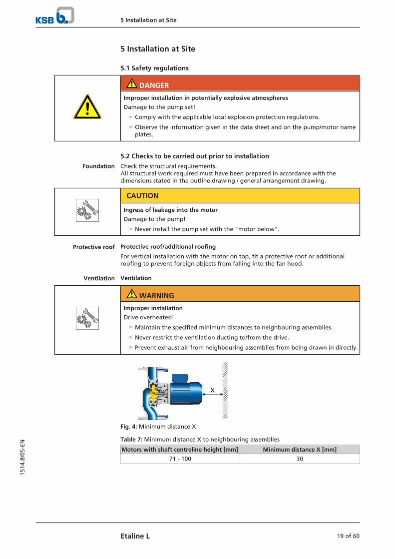
Ventilation Ventilation
WARNING
Improper installation
Drive overheated!
▷ Maintain the specified minimum distances to neighbouring assemblies.
▷ Never restrict the ventilation ducting to/from the drive.
▷ Prevent exhaust air from neighbouring assemblies from being drawn in directly.
X
Fig. 4: Minimum distance X
Table 7: Minimum distance X to neighbouring assemblies
Motors with shaft centreline height [mm] Minimum distance X [mm]
71 - 100 30

5 Installation at Site
20 of 60 Etaline L
1514
.8/0
5-EN
5.3 Installing the pump set
CAUTION
Ingress of leakage into the motor
Damage to the pump!
▷ Never install the pump set with the "motor below".
The pump set may be flanged directly into the piping.
1. Position the pump set on the foundation or in the piping and fasten it.
2. Place a spirit level on the discharge nozzle to align the pump set.
5.4 Piping
5.4.1 Connecting the piping
DANGER
Impermissible loads acting on the pump nozzles
Danger to life from escaping hot, toxic, corrosive or flammable fluids!
▷ Do not use the pump as an anchorage point for the piping.
▷ Anchor the pipes in close proximity to the pump and connect them properlywithout transmitting any stresses or strains.
▷ Observe the permissible forces and moments at the pump nozzles.(ð Section 5.4.2, Page 22)
▷ Take appropriate measures to compensate for thermal expansion of the piping.
CAUTION
Incorrect earthing during welding work at the piping
Destruction of rolling element bearings (pitting effect)!
▷ Never earth the electric welding equipment on the pump or baseplate.
▷ Prevent current flowing through the rolling element bearings.
NOTE
Installing check and shut-off elements in the system is recommended, depending onthe type of plant and pump. However, such elements must not obstruct properdrainage or hinder disassembly of the pump.
ü Suction lift lines have been laid with a rising slope, suction head lines with adownward slope towards the pump.
ü A flow stabilisation section having a length equivalent to at least twice thediameter of the suction flange has been provided upstream of the suction flange.
ü The nominal diameters of the pipelines are at least equal to the nominaldiameters of the pump nozzles.
ü Adapters to larger diameters have a diffuser angle of approximately 8° toprevent excessive pressure losses.
ü The pipelines have been anchored in close proximity to the pump and connectedwithout transmitting any stresses or strains.

5 Installation at Site
21 of 60Etaline L
1514
.8/0
5-EN
CAUTION
Welding beads, scale and other impurities in the piping
Damage to the pump!
▷ Remove any impurities from the piping.
▷ If necessary, install a filter.
▷ Observe the information in (ð Section 7.2.2.1, Page 40) .
1. Thoroughly clean, flush and blow through all vessels, pipelines and connections(especially of new installations).
2. Before installing the pump in the piping, remove the flange covers on thesuction and discharge nozzles of the pump.
3. Check that the inside of the pump is free from any foreign objects. Remove anyforeign objects.
4. If required, install a filter in the piping (see figure: Filter in the piping).
1
2Fig. 5: Filter in the piping
1 Differential pressure gauge 2 Filter
NOTE
Use a filter with laid-in wire mesh (mesh width 0.5 mm, wire diameter 0.25 mm) ofcorrosion-resistant material.Use a filter with a filter area three times the cross-section of the piping.Conical filters have proved suitable.
5. Connect the pump nozzles to the piping.
CAUTION
Aggressive flushing liquid and pickling agent
Damage to the pump!
▷ Match the cleaning operation mode and duration of flushing and pickling tothe casing materials and seal materials used.
5 Installation at Site
22 of 60 Etaline L
1514
.8/0
5-EN
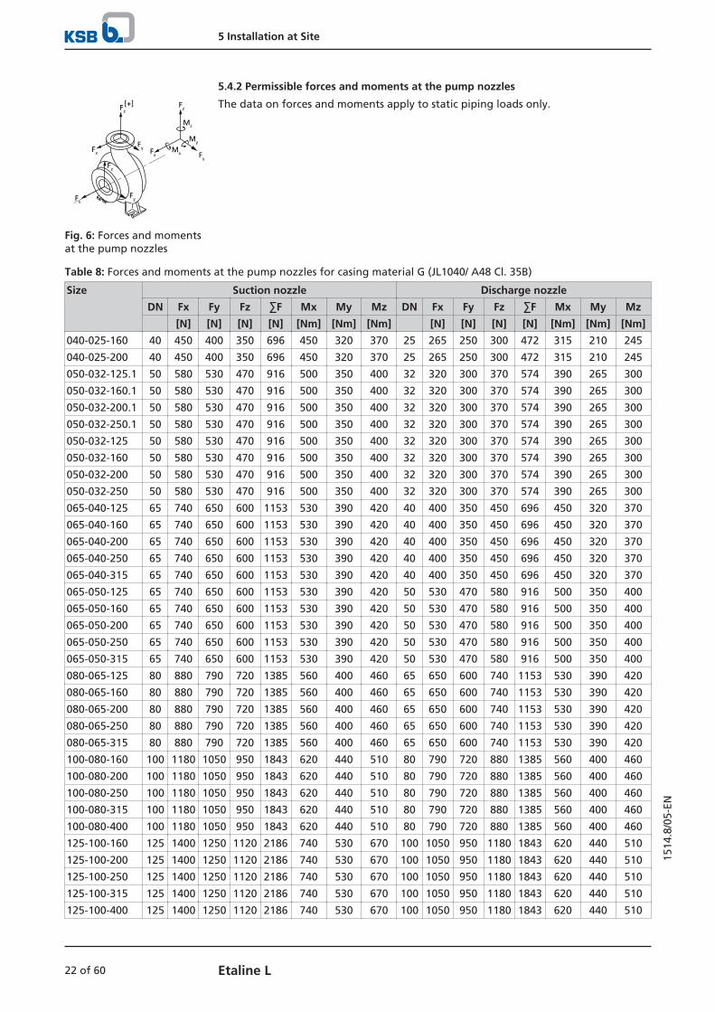
5.4.2 Permissible forces and moments at the pump nozzles[+]Fz
FyFx
FxFy
Fz
Fx Fy
Fz
Mz
My
Mx
Fig. 6: Forces and momentsat the pump nozzles
The data on forces and moments apply to static piping loads only.
Table 8: Forces and moments at the pump nozzles for casing material G (JL1040/ A48 Cl. 35B)
Size Suction nozzle Discharge nozzle
DN Fx Fy Fz ∑F Mx My Mz DN Fx Fy Fz ∑F Mx My Mz
[N] [N] [N] [N] [Nm] [Nm] [Nm] [N] [N] [N] [N] [Nm] [Nm] [Nm]
040-025-160 40 450 400 350 696 450 320 370 25 265 250 300 472 315 210 245
040-025-200 40 450 400 350 696 450 320 370 25 265 250 300 472 315 210 245
050-032-125.1 50 580 530 470 916 500 350 400 32 320 300 370 574 390 265 300
050-032-160.1 50 580 530 470 916 500 350 400 32 320 300 370 574 390 265 300
050-032-200.1 50 580 530 470 916 500 350 400 32 320 300 370 574 390 265 300
050-032-250.1 50 580 530 470 916 500 350 400 32 320 300 370 574 390 265 300
050-032-125 50 580 530 470 916 500 350 400 32 320 300 370 574 390 265 300
050-032-160 50 580 530 470 916 500 350 400 32 320 300 370 574 390 265 300
050-032-200 50 580 530 470 916 500 350 400 32 320 300 370 574 390 265 300
050-032-250 50 580 530 470 916 500 350 400 32 320 300 370 574 390 265 300
065-040-125 65 740 650 600 1153 530 390 420 40 400 350 450 696 450 320 370
065-040-160 65 740 650 600 1153 530 390 420 40 400 350 450 696 450 320 370
065-040-200 65 740 650 600 1153 530 390 420 40 400 350 450 696 450 320 370
065-040-250 65 740 650 600 1153 530 390 420 40 400 350 450 696 450 320 370
065-040-315 65 740 650 600 1153 530 390 420 40 400 350 450 696 450 320 370
065-050-125 65 740 650 600 1153 530 390 420 50 530 470 580 916 500 350 400
065-050-160 65 740 650 600 1153 530 390 420 50 530 470 580 916 500 350 400
065-050-200 65 740 650 600 1153 530 390 420 50 530 470 580 916 500 350 400
065-050-250 65 740 650 600 1153 530 390 420 50 530 470 580 916 500 350 400
065-050-315 65 740 650 600 1153 530 390 420 50 530 470 580 916 500 350 400
080-065-125 80 880 790 720 1385 560 400 460 65 650 600 740 1153 530 390 420
080-065-160 80 880 790 720 1385 560 400 460 65 650 600 740 1153 530 390 420
080-065-200 80 880 790 720 1385 560 400 460 65 650 600 740 1153 530 390 420
080-065-250 80 880 790 720 1385 560 400 460 65 650 600 740 1153 530 390 420
080-065-315 80 880 790 720 1385 560 400 460 65 650 600 740 1153 530 390 420
100-080-160 100 1180 1050 950 1843 620 440 510 80 790 720 880 1385 560 400 460
100-080-200 100 1180 1050 950 1843 620 440 510 80 790 720 880 1385 560 400 460
100-080-250 100 1180 1050 950 1843 620 440 510 80 790 720 880 1385 560 400 460
100-080-315 100 1180 1050 950 1843 620 440 510 80 790 720 880 1385 560 400 460
100-080-400 100 1180 1050 950 1843 620 440 510 80 790 720 880 1385 560 400 460
125-100-160 125 1400 1250 1120 2186 740 530 670 100 1050 950 1180 1843 620 440 510
125-100-200 125 1400 1250 1120 2186 740 530 670 100 1050 950 1180 1843 620 440 510
125-100-250 125 1400 1250 1120 2186 740 530 670 100 1050 950 1180 1843 620 440 510
125-100-315 125 1400 1250 1120 2186 740 530 670 100 1050 950 1180 1843 620 440 510
125-100-400 125 1400 1250 1120 2186 740 530 670 100 1050 950 1180 1843 620 440 510

5 Installation at Site
23 of 60Etaline L
1514
.8/0
5-EN
Size Suction nozzle Discharge nozzle
DN Fx Fy Fz ∑F Mx My Mz DN Fx Fy Fz ∑F Mx My Mz
[N] [N] [N] [N] [Nm] [Nm] [Nm] [N] [N] [N] [N] [Nm] [Nm] [Nm]
150-125-200 150 1750 1600 1400 2754 880 610 720 125 1250 1120 1400 2186 740 530 670
150-125-250 150 1750 1600 1400 2754 880 610 720 125 1250 1120 1400 2186 740 530 670
150-125-315 150 1750 1600 1400 2754 880 610 720 125 1250 1120 1400 2186 740 530 670
150-125-400 150 1750 1600 1400 2754 880 610 720 125 1250 1120 1400 2186 740 530 670
200-150-200 200 2350 2100 1900 3680 1150 800 930 150 1600 1400 1750 2754 880 610 720
200-150-250 200 2350 2100 1900 3680 1150 800 930 150 1600 1400 1750 2754 880 610 720
200-150-315 200 2350 2100 1900 3680 1150 800 930 150 1600 1400 1750 2754 880 610 720
200-150-400 200 2350 2100 1900 3680 1150 800 930 150 1600 1400 1750 2754 880 610 720
Correction coefficients depending on material and temperature (see diagram below).
-30 20 70 120 140
G
S
B
0,7
0,8
0,9
1
1,1
1,3
1,2
°C
Correction coefficient
Fig. 7: Temperature/material correction diagram for casing materials G (EN-GJL-250/A48CL35B), S (EN-GJS-400-15/A536 GR 60-40-18) and B (CC480K-GS/B30 C90700)
Table 9: Forces and moments at the pump nozzles for casing material C (1.4408 / A743 Gr. CF8M)
Size Suction nozzle Discharge nozzle
DN Fx Fy Fz ∑F Mx My Mz DN Fx Fy Fz ∑F Mx My Mz
[N] [N] [N] [N] [Nm] [Nm] [Nm] [N] [N] [N] [N] [Nm] [Nm] [Nm]
040-25-160 40 970 780 650 1404 500 280 410 25 460 410 600 860 370 185 280
040-25-200 40 970 780 650 1404 500 280 410 25 460 410 600 860 370 185 280
050-32-125.1 50 1240 1010 830 1802 650 320 500 32 650 500 780 1132 415 230 320
050-32-160.1 50 1240 1010 830 1802 650 320 500 32 650 500 780 1132 415 230 320
050-32-200.1 50 1240 1010 830 1802 650 320 500 32 650 500 780 1132 415 230 320
050-32-250.1 50 1240 1010 830 1802 650 320 500 32 650 500 780 1132 415 230 320
050-32-125 50 1240 1010 830 1802 650 320 500 32 650 500 780 1132 415 230 320
050-32-160 50 1240 1010 830 1802 650 320 500 32 650 500 780 1132 415 230 320
050-32-200 50 1240 1010 830 1802 650 320 500 32 650 500 780 1132 415 230 320
050-32-250 50 1240 1010 830 1802 650 320 500 32 650 500 780 1132 415 230 320
065-40-125 65 1600 1300 1050 2314 1050 550 780 40 780 640 1000 1421 500 280 415
065-40-160 65 1600 1300 1050 2314 1050 550 780 40 780 640 1000 1421 500 280 415
065-40-200 65 1600 1300 1050 2314 1050 550 780 40 780 640 1000 1421 500 280 415
065-40-250 65 1600 1300 1050 2314 1050 550 780 40 780 640 1000 1421 500 280 415
065-40-315 65 1600 1300 1050 2314 1050 550 780 40 780 640 1000 1421 500 280 415
065-50-125 65 1600 1300 1050 2314 1050 550 780 50 1000 830 1250 1803 650 320 500
065-50-160 65 1600 1300 1050 2314 1050 550 780 50 1000 830 1250 1803 650 320 500
065-50-200 65 1600 1300 1050 2314 1050 550 780 50 1000 830 1250 1803 650 320 500
065-50-250 65 1600 1300 1050 2314 1050 550 780 50 1000 830 1250 1803 650 320 500

5 Installation at Site
24 of 60 Etaline L
1514
.8/0
5-EN
Size Suction nozzle Discharge nozzle
DN Fx Fy Fz ∑F Mx My Mz DN Fx Fy Fz ∑F Mx My Mz
[N] [N] [N] [N] [Nm] [Nm] [Nm] [N] [N] [N] [N] [Nm] [Nm] [Nm]
065-50-315 65 1600 1300 1050 2314 1050 550 780 50 1000 830 1250 1803 650 320 500
080-65-125 80 2000 1550 1300 2845 1330 690 1010 65 1300 1050 1600 2314 1050 550 790
080-65-160 80 2000 1550 1300 2845 1330 690 1010 65 1300 1050 1600 2314 1050 550 790
080-65-200 80 2000 1550 1300 2845 1330 690 1010 65 1300 1050 1600 2314 1050 550 790
080-65-250 80 2000 1550 1300 2845 1330 690 1010 65 1300 1050 1600 2314 1050 550 790
080-65-315 80 2000 1550 1300 2845 1330 690 1010 65 1300 1050 1600 2314 1050 550 790
100-80-160 100 2500 1950 1600 3551 1850 900 1400 80 1550 1300 1950 2810 1350 690 1000
100-80-200 100 2500 1950 1600 3551 1850 900 1400 80 1550 1300 1950 2810 1350 690 1000
100-80-250 100 2500 1950 1600 3551 1850 900 1400 80 1550 1300 1950 2810 1350 690 1000
100-80-315 100 2500 1950 1600 3551 1850 900 1400 80 1550 1300 1950 2810 1350 690 1000
100-80-400 100 2500 1950 1600 3551 1850 900 1400 80 1550 1300 1950 2810 1350 690 1000
125-100-160 125 3400 2700 2200 4867 2500 1300 1950 100 2000 1600 2500 3579 1850 900 1400
125-100-200 125 3400 2700 2200 4867 2500 1300 1950 100 2000 1600 2500 3579 1850 900 1400
125-100-250 125 3400 2700 2200 4867 2500 1300 1950 100 2000 1600 2500 3579 1850 900 1400
125-100-315 125 3400 2700 2200 4867 2500 1300 1950 100 2000 1600 2500 3579 1850 900 1400
125-100-400 125 3400 2700 2200 4867 2500 1300 1950 100 2000 1600 2500 3579 1850 900 1400
150-125-200 150 4300 3450 2850 6206 3200 1600 2450 125 2700 2200 3400 4867 2550 1300 1900
150-125-250 150 4300 3450 2850 6206 3200 1600 2450 125 2700 2200 3400 4867 2550 1300 1900
150-125-315 150 4300 3450 2850 6206 3200 1600 2450 125 2700 2200 3400 4867 2550 1300 1900
150-125-400 150 4300 3450 2850 6206 3200 1600 2450 125 2700 2200 3400 4867 2550 1300 1900
200-150-200 200 6750 5250 4300 9572 4850 2450 3550 150 3450 2850 4300 6206 3150 1600 2450
200-150-250 200 6750 5250 4300 9572 4850 2450 3550 150 3450 2850 4300 6206 3150 1600 2450
200-150-315 200 6750 5250 4300 9572 4850 2450 3550 150 3450 2850 4300 6206 3150 1600 2450
200-150-400 200 6750 5250 4300 9572 4850 2450 3550 150 3450 2850 4300 6206 3150 1600 2450
5.4.3 Vacuum balance line
NOTE
Where fluid has to be pumped out of a vessel under vacuum, installing a vacuumbalance line is recommended.
The following rules apply to vacuum balance lines:
▪ Minimum nominal line diameter 25 mm.
▪ The line extends above the highest permissible fluid level in the vessel.

5 Installation at Site
25 of 60Etaline L
1514
.8/0
5-EN
1 2
5
43
6Fig. 8: Vacuum balance system
1 Vessel under vacuum 2 Vacuum balance line
3 Shut-off element 4 Swing check valve
5 Main shut-off element 6 Vacuum-tight shut-off element
NOTE
An additional line fitted with a shut-off valve (from the pump discharge nozzle tothe balance line) facilitates venting of the pump before start-up.
5.4.4 Auxiliary connections
WARNING
Failure to use or incorrect use of auxiliary connections (e.g. barrier fluid, flushingliquid, etc.)
Risk of injury from escaping fluid!
Risk of burns!
Malfunction of the pump!
▷ Refer to the general arrangement drawing, the piping layout and pumpmarkings (if any) for the quantity, dimensions and locations of auxiliaryconnections.
▷ Use the auxiliary connections provided.
5.5 Enclosure/insulation
WARNING
The volute casing and casing/discharge cover take on the same temperature as thefluid handled
Risk of burns!
▷ Insulate the volute casing.
▷ Fit protective equipment.

5 Installation at Site
26 of 60 Etaline L
1514
.8/0
5-EN
CAUTION
Risk of potentially explosive atmosphere due to insufficient ventilation
Explosion hazard!
▷ Make sure the space between the casing cover/discharge cover and the bearingcover is sufficiently vented.
CAUTION
Heat build-up in the bearing bracket
Damage to the bearing!
▷ Never insulate the bearing bracket, bearing bracket lantern and casing cover.
5.6 Electrical connection
DANGER
Hazardous voltage
Danger of death from electric shock!
▷ Have all work performed only by qualified specialist personnel and only whenthe drive is at a standstill and secured against unintentional start-up. This alsoapplies to auxiliary circuits (e.g. standstill heater).
▷ The drive must not be electrically connected at any point in time when work isperformed on the open terminal box.
▷ Ensure that the rotor cannot turn or be turned at any point in time when workis performed on the open terminal box.
WARNING
Incorrect connection to the mains
Damage to the mains network, short circuit!
▷ Observe the technical specifications of the local energy supply companies.
NOTE
Always protect three-phase motors with a current-dependent overload protectiondevice with additional phase failure protection.
Select the motor connection cables in accordance with IEC 60364, taking into accountthe current load of the cable at the given ambient temperature and the requisiteheat dissipation to IEC / EN 60204-1 as a result of cable routing.
5.6.1 Motor connection inside the terminal box
Observe the following when performing any work on the terminal box:
▪ Always use the original sealing element to close the terminal box so that it isdust- and watertight.
▪ Do not damage components on the inside of the terminal box (e.g. terminalboard and cable connections).
▪ Ensure that no foreign bodies, contamination or moisture are present in theterminal box. Terminal box cable entries to DIN 42925.
▪ Close additional open cable entries, fitting O-rings or suitable gaskets.
▪ Observe prescribed tightening torques for cable glands and other screws/bolts.
▪ When retrofitting cable glands to safeguard the required level of enclosureprotection, ensure that the gasket is seated properly on the outside of theterminal box.

5 Installation at Site
27 of 60Etaline L
1514
.8/0
5-EN
Connecting the motor
1. Check the voltage of the available power supply network against the data onthe motor name plate.
2. Knock out any knock-out openings in the terminal box. While doing this, avoidcausing damage to the terminal board, cable connections, etc. inside theterminal box.
3. Connect the motor in star or delta configuration in accordance with the ratedvoltage (see name plate) and the available power supply network.
N L
1~, configurationTo connect a single-phase motor to the AC power grid, connect the phaseconductor to terminal "L" and neutral to terminal "N".
3~, star configuration
3~, delta configuration
4. Connect the earth conductor (PE).

5 Installation at Site
28 of 60 Etaline L
1514
.8/0
5-EN
5.6.1.1 Tightening torques
Unless other tightening torques are indicated on the motor the following torquesshall be used:
Table 10: Tightening torques
Thread [Nm]
M4 1,2
M5 2,0
M6 3,0
M8 6,0
M10 10,0

6 Commissioning/Start-up/Shutdown
29 of 60Etaline L
1514
.8/0
5-EN
6 Commissioning/Start-up/Shutdown
6.1 Commissioning/Start-up/Shutdown
DANGER
Hazardous voltage
Danger of death from electric shock!
▷ Have all work performed only by qualified specialist personnel and only whenthe drive is at a standstill and secured against unintentional start-up. This alsoapplies to auxiliary circuits (e.g. standstill heater).
▷ The drive must not be electrically connected at any point in time when work isperformed on the open terminal box.
▷ Ensure that the rotor cannot turn or be turned at any point in time when workis performed on the open terminal box.
Before commissioning and whenever returning the product to service, perform theelectrical safety checks stipulated by EN 60204-1.
6.1.1 Prerequisites for commissioning/start-up
Before commissioning/starting up the pump set, make sure that the followingconditions are met:
▪ The drive has been mounted and aligned correctly.
▪ The operating conditions have been verified against the name plate data.
▪ The earth connection and potential equalisation connections have been madecorrectly.
▪ All fastening bolts/screws, connecting elements and electrical connections havebeen tightened to the specified tightening torques.
▪ Measures have been taken to prevent accidental contact with moving and liveparts.
▪ Components (cables, etc.) that are sensitive to temperature do not come intocontact with the motor housing.
▪ The pump set has been properly connected to the power supply and is equippedwith all protection devices.
▪ The pump has been primed with the fluid to be handled. The pump has beenvented.
▪ The direction of rotation has been checked.
▪ All auxiliary connections required are connected and operational.
▪ After prolonged shutdown of the pump (set), the activities required for returningthe equipment to service have been carried out. (ð Section 6.4, Page 36)
6.1.2 Checking earth conductor connection
Check that the earth conductor has been correctly connected in accordance withEN60204.
6.1.3 Checking insulation resistance
Prior to commissioning and following prolonged storage or standstill periods, theinsulation resistance will need to be checked and verified.
NOTE
If windings have been dried after having been repaired or cleaned, bear in mindthat the insulation resistance of warm windings is lower. The insulation resistancecan only be correctly evaluated after converting to the reference temperature of25 °C.

6 Commissioning/Start-up/Shutdown
30 of 60 Etaline L
1514
.8/0
5-EN
The insulation resistance of the stator winding must equal at least 1.5 megohms inmotors for 220 -1000 V.
6.1.4 Filling in lubricants
Grease-lubricated bearings have been packed with grease at the factory.
6.1.5 Priming and venting the pump
DANGER
Formation of a potentially explosive atmosphere inside the pump
Explosion hazard!
▷ Before starting up the pump set, vent the pump and suction line and primeboth with the fluid to be handled.
CAUTION
Increased wear due to dry running
Damage to the pump set!
▷ Never operate the pump set without liquid fill.
▷ Never close the shut-off element in the suction line and/or supply line duringpump operation.
1. Vent the pump and suction line and prime both with the fluid to be handled.Connection 6D can be used for venting (see drawing of auxiliary connections).For vertical installation with the motor on top, use connection 5B (if provided)for venting (see drawing of auxiliary connections).
2. Fully open the shut-off element in the suction line.
3. Fully open all auxiliary feed lines (barrier fluid, flushing liquid, etc.), if any.
4. Open the shut-off element, if any, in the vacuum balance line and close thevacuum-tight shut-off element, if any.
WARNING
Hot water escaping under pressure when the vent plug is opened
Risk of electric shock!
Risk of scalding!
▷ Protect the electric components against escaping fluid.
▷ Wear protective clothing (e.g. gloves).
NOTE
For design-inherent reasons some unfilled volume in the hydraulic system cannot beexcluded after the pump has been primed for commissioning/start-up. However,once the motor is started up the pumping effect will immediately fill this volumewith the fluid handled.
6.1.6 Checking the direction of rotation
DANGER
Temperature increase resulting from contact between rotating and stationarycomponents
Damage to the pump set!
▷ Never check the direction of rotation by starting up the unfilled pump set.

6 Commissioning/Start-up/Shutdown
31 of 60Etaline L
1514
.8/0
5-EN
WARNING
Hands inside the pump casing
Risk of injuries, damage to the pump!
▷ Always disconnect the pump set from the power supply and secure it againstunintentional start-up before inserting your hands or other objects into thepump.
WARNING
Parts flying off
Personal injury and damage to property!
▷ When checking the direction of rotation with the coupling removed, secure therespective keys to protect them from being thrown off.
CAUTION
Drive and pump running in the wrong direction of rotation
Damage to the pump!
▷ Refer to the arrow indicating the direction of rotation on the pump.
▷ Check the direction of rotation. If required, check the electrical connection andcorrect the direction of rotation.
The correct direction of rotation of the motor and pump is anti-clockwise (seen fromthe motor end).
1. Start the motor and stop it again immediately to determine the motor'sdirection of rotation.
2. Check the direction of rotation. The motor's direction of rotation must match the arrow indicating the directionof rotation on the pump.
3. If the motor is running in the wrong direction of rotation, check the electricalconnection of the motor and the control system if applicable.
6.1.7 Start-up
DANGER
Non-compliance with the permissible pressure and temperature limits if the pumpis operated with the suction and discharge lines closed.
Leakage of hot or toxic fluids!
▷ Never operate the pump with the shut-off elements in the suction line and/ordischarge line closed.
▷ Only start up the pump set with the discharge-side gate valve slightly or fullyopen.
DANGER
Excessive temperatures due to dry running or excessive gas content in the fluidhandled
Damage to the pump set!
▷ Never operate the pump set without a liquid fill.
▷ Prime the pump as per operating instructions.
▷ Always operate the pump within the permissible operating range.

6 Commissioning/Start-up/Shutdown
32 of 60 Etaline L
1514
.8/0
5-EN
CAUTION
Abnormal noises, vibrations, temperatures or leakage
Damage to the pump!
▷ Switch off the pump (set) immediately.
▷ Eliminate the causes before returning the pump set to service.
ü The system piping has been cleaned.
ü Pump, suction line and inlet tank, if fitted, have been vented and primed withthe fluid to be handled.
ü The lines for priming and venting have been closed.
CAUTION
Start-up against open discharge line
Motor overload!
▷ Make sure the motor has sufficient power reserves.
▷ Use a soft starter.
▷ Use speed control.
1. Fully open the shut-off element in the suction head line/suction lift line.
2. Close or slightly open the shut-off element in the discharge line.
3. Start up the motor.
4. Immediately after the pump has reached full rotational speed, slowly open theshut-off element in the discharge line and adjust it to comply with the dutypoint.
DANGER
Seal leakages at operating temperature
Leakage of hot or toxic fluid handled!
▷ Once the operating temperature has been reached, re-tighten the hexagonsocket head cap screws between casing and casing cover.
6.1.8 Checking the shaft seal
Mechanical seal The mechanical seal only leaks slightly or invisibly (as vapour) during operation.Mechanical seals are maintenance-free.
6.1.9 Shutdown
CAUTION
Heat build-up inside the pump
Damage to the shaft seal!
▷ Depending on the type of installation, the pump set requires sufficient after-run time – with the heat source switched off – until the fluid handled hascooled down.

6 Commissioning/Start-up/Shutdown
33 of 60Etaline L
1514
.8/0
5-EN
CAUTION
Backflow of fluid handled is not permitted
Motor or winding damage! Mechanical seal damage!
▷ Close the shut-off elements.
ü The shut-off element in the suction line is and remains open.
1. Close the shut-off element in the discharge line.
2. Switch off the motor and make sure the pump set runs down smoothly to astandstill.
NOTE
If the discharge line is equipped with a non-return or check valve, the shut-offelement may remain open provided that the system conditions and systemregulations are considered and observed.
For prolonged shutdown periods:
1. Close the shut-off element in the suction line.
2. Close any auxiliary lines. If the fluid to be handled is fed in under vacuum, also supply the shaft seal withbarrier fluid during standstill.
CAUTION
Risk of freezing during prolonged pump shutdown periods
Damage to the pump!
▷ Drain the pump and the cooling/heating chambers (if any) or otherwise protectthem against freezing.
6.2 Operating limits
DANGER
Non-compliance with operating limits for pressure, temperature and speed
Explosion hazard!
Leakage of hot or toxic fluid handled!
▷ Comply with the operating data indicated in the data sheet.
▷ Never use the pump to handle fluids it is not designed for.
▷ Avoid prolonged operation against a closed shut-off element.
▷ Never operate the pump at temperatures exceeding those specified in the datasheet or on the name plate unless the written consent of the manufacturer hasbeen obtained.
6.2.1 Ambient temperature
CAUTION
Operation outside the permissible ambient temperature
Damage to the pump (set)!
▷ Observe the specified limits for permissible ambient temperatures.
Observe the following parameters and values during operation:

6 Commissioning/Start-up/Shutdown
34 of 60 Etaline L
1514
.8/0
5-EN
Table 11: Permissible ambient temperatures
Permissible ambient temperature Value
Maximum 40 °C
Minimum See data sheet.
6.2.2 Frequency of starts
DANGER
Excessive surface temperatures of the motor
Explosion hazard!
▷ The limit value for stopping the pump must never exceed the specified surfacetemperature of the respective temperature class.
▷ If the specified surface temperature of the respective temperature class isexceeded, immediately switch off the pump set and determine the cause.
The frequency of starts is determined by the maximum temperature increase of themotor. The frequency of starts depends on the power reserves of the motor insteady-state operation and on the starting conditions (DOL starting, star-deltastarting, moments of inertia, etc). If the start-ups are evenly spaced over the periodindicated, the following limits serve as orientation for start-up with the discharge-side shut-off valve slightly open:
Table 12: Frequency of starts
Material Maximum frequency of starts
[Start-ups/hour]
G (EN-GJL-150) 15
B (G-CuSn10Zn) 6
P (PSu-GF30) 6
CAUTION
Re-starting while motor is still running down
Damage to the pump (set)!
▷ Do not re-start the pump set before the pump rotor has come to a standstill.
6.2.3 Fluid handled
6.2.3.1 Flow rate
Table 13: Flow rate
Temperature range (t) Minimum flow rate Maximum flow rate
-30 to +70 ℃ ≈ 15 % of QOpt4) See hydraulic characteristic
curves> 70 to +140 °C ≈ 25 % of QOpt4)
The calculation formula below can be used to check if an additional heat build-upcould lead to a dangerous temperature increase at the pump surface.
××
×
4) Best efficiency point

6 Commissioning/Start-up/Shutdown
35 of 60Etaline L
1514
.8/0
5-EN
Table 14: Key
Symbol Description Unit
c Specific heat capacity J/kg K
g Acceleration due to gravity m/s²
H Pump discharge head m
Tf Fluid temperature °C
TO Temperature at the casing surface °C
Pump efficiency at duty point -
Temperature difference K
6.2.3.2 Density of the fluid handled
The power input of the pump set will change in proportion to the density of the fluidhandled.
CAUTION
Impermissibly high density of the fluid handled
Motor overload!
▷ Observe the information about fluid density in the data sheet.
▷ Make sure the motor has sufficient power reserves.
6.2.3.3 Abrasive fluids
Do not exceed the maximum permissible solids content specified in the data sheet.When the pump handles fluids containing abrasive substances, increased wear of thehydraulic system and shaft seal are to be expected. In this case, reduce the commonlyrecommended inspection intervals.
6.2.4 Voltages and frequencies
Motor operation off the rated point will cause a rise in motor temperature. A voltagetolerance of ± 5 % and a frequency tolerance of ± 2 % are permissible.
Any situation where both the voltage and the frequency tolerance applysimultaneously shall be governed by the provisions of range A as described inEN60034-1. The motors can be operated continuously in range A. In accordance withEN60034-1, prolonged operation in range B is not recommended.
6.2.5 Maximum permissible speed
Comply with the rotational speed indicated on the name plate.
6.2.6 Altitude
▪ ≤ 1000 m above MSL: without power derating
▪ > 1000 m above MSL: installation at altitudes of up to 4000 m above MSL ispossible with power derated by 3.8 % per 500 m.
6.3 Shutdown/storage/preservation
6.3.1 Measures to be taken for shutdown
The pump (set) remains installed
ü Sufficient fluid is supplied for the functional check run of the pump.
1. For prolonged shutdown periods, start up the pump (set) regularly betweenonce a month and once every three months for approximately five minutes.
ð This will prevent the formation of deposits within the pump and the pumpintake area.

6 Commissioning/Start-up/Shutdown
36 of 60 Etaline L
1514
.8/0
5-EN
The pump (set) is removed from the piping and stored
ü The pump has been properly drained. (ð Section 7.3, Page 41)
ü The safety instructions for dismantling the pump have been observed.
1. Spray-coat the inside wall of the pump casing and, in particular, the impellerclearance areas with a preservative.
2. Spray the preservative through the suction nozzle and discharge nozzle.It is advisable to then close the pump nozzles (e.g. with plastic caps).
3. Oil or grease all exposed machined parts and surfaces of the pump (withsilicone-free oil or grease, food-approved if required) to protect them againstcorrosion.Observe the additional instructions on preservation.
If the pump set is to be stored temporarily, only preserve the wetted componentsmade of low-alloy materials. Commercially available preservatives can be used forthis purpose. Observe the manufacturer's instructions for application/removal.
6.4 Returning to serviceFor returning the equipment to service observe the sections on commissioning/start-up and the operating limits.
In addition, carry out all servicing/maintenance operations before returning thepump (set) to service. (ð Section 7, Page 37)
WARNING
Failure to re-install or re-activate protective devices
Risk of injury from moving parts or escaping fluid!
▷ As soon as the work is completed, properly re-install and re-activate any safety-relevant devices and protective devices.
NOTE
If the equipment has been out of service for more than one year, replace allelastomer seals.

7 Servicing/Maintenance
37 of 60Etaline L
1514
.8/0
5-EN
7 Servicing/Maintenance
7.1 Safety regulations
DANGER
Sparks produced during servicing work
Explosion hazard!
▷ Observe the safety regulations in force at the place of installation!
▷ Never open an energised pump set.
▷ Always perform maintenance work on pump sets outside potentially explosiveatmospheres only.
DANGER
Improperly serviced pump set
Explosion hazard!
Damage to the pump set!
▷ Service the pump set regularly.
▷ Prepare a maintenance schedule with special emphasis on lubricants, shaft sealand coupling.
The operator ensures that maintenance, inspection and installation are performed byauthorised, qualified specialist personnel who are thoroughly familiar with themanual.
WARNING
Unintentional starting of the pump set
Risk of injury by moving components and shock currents!
▷ Ensure that the pump set cannot be started unintentionally.
▷ Always make sure the electrical connections are disconnected before carryingout work on the pump set.
WARNING
Fluids handled, consumables and supplies which are hot and/or pose a healthhazard
Risk of injury!
▷ Observe all relevant laws.
▷ When draining the fluid take appropriate measures to protect persons and theenvironment.
▷ Decontaminate pumps which handle fluids posing a health hazard.
WARNING
Insufficient stability
Risk of crushing hands and feet!
▷ During assembly/dismantling, secure the pump (set)/pump parts to preventtilting or tipping over.
A regular maintenance schedule will help avoid expensive repairs and contribute totrouble-free, reliable operation of the pump, pump set and pump parts with aminimum of servicing/maintenance expenditure and work.

7 Servicing/Maintenance
38 of 60 Etaline L
1514
.8/0
5-EN
NOTE
All maintenance work, service work and installation work can be carried out by KSBService or authorised workshops. For contact details please refer to the enclosed"Addresses" booklet or visit "www.ksb.com/contact" on the Internet.
Never use force when dismantling and reassembling the pump set.
7.2 Servicing/Inspection
7.2.1 Supervision of operation
DANGER
Rotating or live parts
Death, serious injury or damage to property!
▷ If covers have to be removed, de-energise the motor beforehand.
▷ Avoid touching live or rotating parts.
DANGER
Incorrectly serviced shaft seal
Fire hazard!
Hot fluids escaping!
Damage to the pump set!
▷ Regularly service the shaft seal.
DANGER
Excessive temperatures as a result of bearings running hot or defective bearingseals
Fire hazard!
Damage to the pump set!
▷ Regularly check the rolling element bearings for running noises.
DANGER
Hot surface
Risk of burns!
▷ Never touch a motor when it is in operation.
▷ Let the motor cool down.
▷ Only remove covers if indicated.
WARNING
Condensing air humidity inside the motor if the motor and/or ambienttemperatures frequently change
Risk of corrosion by condensation!
▷ Always observe the information provided on ambient conditions.

7 Servicing/Maintenance
39 of 60Etaline L
1514
.8/0
5-EN
CAUTION
Impermissibly high temperature of fluid handled
Damage to the pump!
▷ Prolonged operation against a closed shut-off element is not permitted(heating up of the fluid).
▷ Observe the temperature limits in the data sheet and in the section onoperating limits.
CAUTION
Increased wear due to dry running
Damage to the pump set!
▷ Never operate the pump set without liquid fill.
▷ Never close the shut-off element in the suction line and/or supply line duringpump operation.
While the pump is in operation, observe and check the following:
▪ The pump must run quietly and free from vibrations at all times.
▪ Check the shaft seal. (ð Section 6.1.8, Page 32)
▪ Check the static sealing elements for leakage.
▪ Check the rolling element bearings for running noises.Vibrations, noise and an increase in current input occurring during unchangedoperating conditions indicate wear.
▪ Monitor the correct functioning of any auxiliary connections.
▪ Monitor the stand-by pump.To make sure that stand-by pumps are ready for operation, start them up once aweek.
▪ Monitor the bearing temperature.The bearing temperature must not exceed 90 °C (measured on the motorhousing).
▪ Deviations from normal operation such as increased power consumption,temperatures or vibrations, unusual noises or odours, tripping of monitoringdevices, etc.
CAUTION
Operation outside the permissible bearing temperature
Damage to the pump!
▷ The bearing temperature of the pump (set) must never exceed 90 °C (measuredon the outside of the motor housing).
NOTE
After commissioning, increased temperatures may occur at grease-lubricated rollingelement bearings due to the running-in process. The final bearing temperature isonly reached after a certain period of operation (up to 48 hours depending on theconditions).

7 Servicing/Maintenance
40 of 60 Etaline L
1514
.8/0
5-EN
7.2.2 Inspection work
DANGER
Excessive temperatures caused by friction, impact or frictional sparks
Fire hazard!
Damage to the pump set!
▷ Regularly check the cover plates, plastic components and other guards ofrotating parts for deformation and sufficient distance from rotating parts.
7.2.2.1 Cleaning filters
CAUTION
Insufficient inlet pressure due to clogged filter in the suction line
Damage to the pump!
▷ Monitor contamination of filter with suitable means (e.g. differential pressuregauge).
▷ Clean filter at appropriate intervals.
7.2.2.2 Checking the motor
Carry out the following measures:
▪ Check that the electrical connections are firmly seated.
▪ Verify that ventilation paths are unobstructed and clean.
▪ Check that the terminal box is closed safely.
7.2.3 Lubrication and lubricant change
7.2.3.1 Maintenance of rolling element bearings
Maintenance for long-termstorage
Extended storage periods decrease the service life of the lubricating grease. This inturn reduces the service life of the bearings.
▪ The rolling element bearings should be completely replaced after a storageperiod of more than 4 years.
Maintenance for normaloperating conditions
Recommended bearing replacement interval under normal operating conditions:
Table 15: Bearing replacement
Ambient temperature Bearing replacement interval
40 °C 20.000 h
NOTE
The bearing service life is reduced e.g. for vertical installations, high vibration andshock loads, frequent reversing duty, higher ambient temperature and higherrotating speeds.
7.2.3.1.1 Grease lubrication
The bearings are supplied packed with high-quality lithium-soap grease.
7.2.3.1.2 Intervals
The rolling element bearings of the motor are grease-packed and maintenance-free.

7 Servicing/Maintenance
41 of 60Etaline L
1514
.8/0
5-EN
7.3 Drainage/cleaning
WARNING
Fluids handled, consumables and supplies which are hot and/or pose a healthhazard
Hazard to persons and the environment!
▷ Collect and properly dispose of flushing fluid and any fluid residues.
▷ Wear safety clothing and a protective mask if required.
▷ Observe all legal regulations on the disposal of fluids posing a health hazard.
1. Use connection 6B to drain the fluid handled (see drawing of auxiliaryconnections).
2. Always flush the system if it has been used for handling noxious, explosive, hotor other hazardous fluids.Always flush and clean the pump before transporting it to the workshop.Provide a certificate of decontamination for the pump. (ð Section 13, Page 55)
7.4 Dismantling the pump set
7.4.1 General information/Safety regulations
DANGER
Insufficient preparation of work on the pump (set)
Risk of injury!
▷ Properly shut down the pump set. (ð Section 6.1.9, Page 32)
▷ Close the shut-off elements in the suction line and discharge line.
▷ Drain the pump and release the pump pressure. (ð Section 7.3, Page 41)
▷ Shut off any auxiliary feed lines.
▷ Allow the pump set to cool down to ambient temperature.
WARNING
Unqualified personnel performing work on the pump (set)
Risk of injury!
▷ Always have repair work and maintenance work performed by specially trained,qualified personnel.
DANGER
Hot surface
Risk of burns!
▷ Never touch a motor when it is in operation.
▷ Let the motor cool down.
▷ Only remove covers if indicated.
WARNING
Improper lifting/moving of heavy assemblies or components
Personal injury and damage to property!
▷ Use suitable transport devices, lifting equipment and lifting tackle to moveheavy assemblies or components.
Always observe the safety instructions and information.

7 Servicing/Maintenance
42 of 60 Etaline L
1514
.8/0
5-EN
For dismantling and reassembly observe the exploded views and the generalassembly drawing.
In case of damage you can always contact our service staff.
Prior to dismantling, label the respective assignment of fastening elements as well asthe arrangement of internal connections for future reassembly.
Drive ▪ Replace any corroded bolts/screws.
▪ Never damage the insulation of live parts.
▪ Document position of any rating and additional plates or labels to be removed.
▪ Avoid damaging the centring spigots.
Protect rolling element bearings against the ingress of contamination and moisture.
NOTE
All maintenance work, service work and installation work can be carried out by KSBService or authorised workshops.
NOTE
After a prolonged period of operation the individual components may be hard topull off the shaft. If this is the case, use a brand name penetrating agent and/or - ifpossible - an appropriate puller.
7.4.2 Preparing the pump set
1. De-energise the pump set and secure it against unintentional start-up.
2. Reduce pressure in the piping by opening a consumer installation.
3. Disconnect and remove all auxiliary pipework.
7.4.3 Dismantling the complete pump set
NOTE
The pump casing can remain installed in the piping for further dismantling.
ü The notes and steps stated (ð Section 7.4.1, Page 41) into(ð Section 7.4.2, Page 42) have been observed/carried out.
1. Disconnect the discharge and suction nozzles from the piping.
2. Depending on the pump/motor size, remove the supports from the pump set.
3. Remove the complete pump set from the piping.
7.4.4 Removing the back pull-out unit
WARNING
Back pull-out unit tilting
Risk of squashing hands and feet!
▷ Suspend or support the back pull-out unit at the pump end.
ü The notes and steps stated (ð Section 7.4.1, Page 41) into (ð Section 7.4.3, Page 42) have been observed/carried out.
1. If required, suspend or support the back pull-out unit to prevent it from tippingover.
2. Undo hexagon socket head cap screws 914.42 at the casing cover.
3. Pull the back pull-out unit out of the volute casing.

7 Servicing/Maintenance
43 of 60Etaline L
1514
.8/0
5-EN
4. Remove and dispose of O-ring 412.50.
5. Place the back pull-out unit on a clean and level surface.
7.4.5 Removing the impeller
ü The notes and steps stated (ð Section 7.4.1, Page 41) into (ð Section 7.4.4, Page 42) have been observed/carried out.
ü The back pull-out unit has been placed in a clean and level assembly area.
1. Undo hexagon socket head cap screw 914.21 (right-hand thread!).Take safety device 930 and washer 554.03 off the impeller hub.
2. Remove impeller 230 with an impeller removal tool.
3. Place impeller 230 on a clean and level surface.
4. Take key 940.01 out of the shaft of motor 800.
7.4.6 Removing the mechanical seal
ü The notes and steps stated (ð Section 7.4.1, Page 41) into (ð Section 7.4.5, Page 43) have been observed/carried out.
ü The back pull-out unit has been placed in a clean and level assembly area.
1. Prise circlip 932 out of the groove with a screwdriver and pull it off the shaft ofmotor 800.
2. Remove the rotating assembly of mechanical seal 433 (primary ring) from theshaft of motor 800.
3. Prise the stationary assembly of mechanical seal 433 (mating ring) out of cap 580with a screwdriver, taking care not to damage the mating ring!
7.5 Reassembling the pump set
7.5.1 General information/Safety regulations
WARNING
Improper lifting/moving of heavy assemblies or components
Personal injury and damage to property!
▷ Use suitable transport devices, lifting equipment and lifting tackle to moveheavy assemblies or components.
CAUTION
Improper reassembly
Damage to the pump!
▷ Reassemble the pump (set) in accordance with the general rules of soundengineering practice.
▷ Use original spare parts only.
Sequence Always reassemble the pump in accordance with the corresponding general assemblydrawing.
Sealing elements Check O-rings for any damage and replace by new O-rings, if required.
Always use new gaskets. Make sure that new gaskets have the same thickness as theold ones.
Always fit gaskets of asbestos-free materials or graphite without using lubricants(e.g. copper grease, graphite paste).
Assembly adhesives Avoid the use of assembly adhesives, if possible.
Should an assembly adhesive be required after all, use a commercially availablecontact adhesive (e.g. Pattex) or sealant (e.g. HYLOMAR or Epple 33).

7 Servicing/Maintenance
44 of 60 Etaline L
1514
.8/0
5-EN
Only apply adhesive at selected points and in thin layers.
Never use quick-setting adhesives (cyanoacrylate adhesives).
Coat the locating surfaces of the individual components with graphite or similarbefore reassembly.
Tightening torques For reassembly, tighten all screws and bolts as specified in this manual.
7.5.2 Fitting the mechanical seal
Installing themechanical seal
The following rules must be observed when installing the mechanical seal:
▪ Work cleanly and accurately.
▪ Only remove the protective wrapping of the contact faces immediately beforeinstallation takes place.
▪ Prevent any damage to the sealing surfaces or O-rings.
ü The notes and steps stated in (ð Section 7.5.1, Page 43) have been observed/carried out.
ü The bearing assembly as well as the individual parts have been placed in a cleanand level assembly area.
ü All dismantled parts have been cleaned and checked for wear.
ü Any damaged or worn parts have been replaced by original spare parts.
ü The sealing surfaces have been cleaned.
1. Clean the mating ring location in cap 580.
CAUTION
Elastomers in contact with oil/grease
Shaft seal failure!
▷ Use water as assembly lubricant.
▷ Never use oil or grease as assembly lubricant.
2. Carefully insert the mating ring. Make sure that pressure is applied evenly.
3. Fit the rotating assembly of mechanical seal 433 (primary ring) on the shaft ofmotor 800.
7.5.3 Fitting the impeller
ü The notes and steps stated in (ð Section 7.5.1, Page 43) to (ð Section 7.5.2, Page 44) have been observed/carried out.
ü The pre-assembled unit (motor, cap, drive lantern, casing cover) as well as theindividual parts have been placed in a clean and level assembly area.
ü All dismantled parts have been cleaned and checked for wear.
ü Any damaged or worn parts have been replaced by original spare parts.
ü The sealing surfaces have been cleaned.
1. Slide circlip 932 onto the shaft of motor 800 until it snaps into the groove.
2. Insert key 940.01 and slide impeller 230 onto the shaft of motor 800.
3. Fasten hexagon socket head cap screw 914.21 with safety device 930 and washer554.03. (ð Section 7.6, Page 45)

7 Servicing/Maintenance
45 of 60Etaline L
1514
.8/0
5-EN
7.5.4 Installing the back pull-out unit
WARNING
Back pull-out unit tilting
Risk of squashing hands and feet!
▷ Suspend or support the back pull-out unit at the pump end.
ü The notes and steps stated in (ð Section 7.5.1, Page 43) to (ð Section 7.5.3, Page 44) have been observed/carried out.
ü Any damaged or worn parts have been replaced by original spare parts.
ü The sealing surfaces have been cleaned.
1. Suspend or support the back pull-out unit to prevent it from tipping over.
2. Fit a new O-ring 412.50 on cap 580.
3. Insert the back pull-out unit into volute casing 102.
4. Tighten hexagon socket head cap screws 914.12 on casing cover 161. (ð Section 7.6, Page 45)
7.6 Tightening torques
Table 16: Tightening torques for bolted/screwed connections at the pump
Part No.5) Thread [Nm]
903.02 1/4 55
903.39 1/4 55
914.21 M4 2,5
M5 4
M6 7
914.42 M6 10
M8 25
7.7 Spare parts stock
7.7.1 Ordering spare parts
Always quote the following data when ordering replacement or spare parts:
▪ Type series
▪ Size
▪ Material variant
▪ Seal code
▪ Material number
▪ Series code
Refer to the name plate for all data.
Also specify the following data:
▪ Part number and description
▪ Quantity of spare parts
▪ Shipping address
▪ Mode of dispatch (freight, mail, express freight, air freight)
5) See general assembly drawing.

7 Servicing/Maintenance
46 of 60 Etaline L
1514
.8/0
5-EN
7.7.2 Recommended spare parts stock for 2 years' operation to DIN 24296
Table 17: Quantity of spare parts for recommended spare parts stock
Part No. Description Number of pumps (including stand-by pumps)
2 3 4 5 6 and 7 8 and 9 10 andmore
230 Impeller 1 1 1 2 2 2 20 %
412.50 O-ring 4 6 8 8 9 10 100 %
433 Mechanical seal 1 1 2 2 2 3 25 %
914.21 Hexagon socket head capscrew
1 1 1 2 2 2 20 %
930 Safety device 1 1 1 2 2 2 20 %

8 Trouble-shooting
47 of 60Etaline L
1514
.8/0
5-EN
8 Trouble-shooting
WARNING
Improper work to remedy faults
Risk of injury!
▷ For any work performed to remedy faults, observe the relevant informationgiven in this instruction manual and/or in the product literature provided by theaccessories manufacturer.
If problems occur that are not described in the following table, consultation with KSBService is required.
A Pump delivers insufficient flow rate
B Motor is overloaded
C Motor protection switch / thermistor trip device trips the unit
D Increased bearing temperature
E Leakage at the pump
F Excessive leakage at the shaft seal
G Vibrations during pump operation
H Impermissible temperature increase in the pump
I Drive does not start.
Table 18: Trouble-shooting
A B C D E F G H I Possible cause Remedy6)
✘ - - - - - - - - Pump delivers against an excessively highpressure.
Re-adjust to duty point.
Check system for impurities.Fit a larger impeller.6)
Increase the speed (frequency inverter).
✘ - - - - - ✘ ✘ - Pump and/or piping are not completelyvented or primed.
Vent or prime.
✘ - - - - - - - - Supply line or impeller clogged Remove deposits in the pump and/orpiping.
✘ - - - - - - - - Formation of air pockets in the piping Alter piping layout.Fit vent valve.
✘ - - - - - ✘ ✘ - Suction lift is too high/NPSHavailable (positivesuction head) is too low.
Check/alter liquid level (open system).
Increase system pressure (closed system).Install pump at a lower level.Fully open the shut-off element in thesuction line.Change suction line, if the friction lossesin the suction line are too high.Check any strainers installed/suctionopening.Observe permissible speed of pressurefall.
✘ - - - - - - - - Wrong direction of rotation Check the electrical connection of themotor and the control system if any.
✘ - - - - - - - - Speed is too low.
- Operation with frequency inverter
- Operation without frequency inverter
- Increase voltage/frequency at thefrequency inverter in the permissiblerange.- Check electrical voltage.
✘ - - - - - ✘ - - Wear of internal components Replace worn components by new ones.
6) Pump pressure must be released before attempting to remedy faults on parts which are subjected to pressure.

8 Trouble-shooting
48 of 60 Etaline L
1514
.8/0
5-EN
A B C D E F G H I Possible cause Remedy6)
- ✘ - - - - ✘ - - Pump back pressure is lower thanspecified in the purchase order.
Re-adjust to duty point.In the case of persistent overloading, turndown impeller.6)
- ✘ - - - - - - - Density or viscosity of fluid handledhigher than stated in purchase order
Consult the manufacturer.
- - - - - ✘ - - - Use of unsuitable shaft seal materials Change the material combination. 6)
- ✘ ✘ - - - - - - Speed is too high. Reduce speed.6)
- - - - ✘ - - - - Tie bolts/sealing element defective Fit new sealing element between volutecasing and casing cover.Re-tighten the bolts.
- - - - - ✘ - - - Worn shaft seal Fit new shaft seal.
- - - - - ✘ - - - Dismantle to find out. Correct.Fit new shaft seal, if required.
- - - - - ✘ - - - Vibrations during pump operation Correct the suction conditions.Re-balance the impeller.Increase pressure at the pump suctionnozzle.
- - - ✘ - ✘ ✘ - - Pump is warped or sympathetic vibrationsin the piping.
Check the piping connections and securefixing of pump; if required, reducedistances between the pipe clamps.Fix the pipelines using anti-vibrationmaterial.
- - - ✘ - - - - - Increased axial thrust Clean balancing holes in the impeller.
✘ ✘ - - - - - - - Motor is running on 2 phases only. Replace the defective fuse.Check the electric cable connections.
Check the motor winding.
- - - - - - ✘ - - Rotor out of balance Clean the impeller.Re-balance the impeller.
- - - ✘ - - ✘ ✘ - Flow rate is too low. Increase the minimum flow rate.
- - ✘ - - - - - - Incorrect setting of motor protectionswitch
Check setting.
Fit new motor protection switch.
- - - - - - - - ✘ No electrical voltage Check mains fuses, mains voltage andoperating status of the frequencyinverter.
- - - - - - - - ✘ Mains cables connected incorrectly/Fault in supply line
Check wiring.

9 Related Documents
49 of 60Etaline L
1514
.8/0
5-EN
9 Related Documents
9.1 Installation types
Horizontal installation
Fig. 9: Horizontal installation, direction of flow from bottom to top
Fig. 10: Horizontal installation, direction of flow from top to bottom
The volute casing and/or back pull-out unit must be turned by 180° so that theterminal box remains in its current position on top.
1146:3/1
Fig. 11: Horizontal installation (for example under the ceiling)
The volute casing and/or back pull-out unit must be turned by 90° so that theterminal box remains in its current position on top.
1
Fig. 12: Horizontal installation with blind flange (1 = blind flange, accessories)
If one of the pumps needs to be serviced, the pump chamber can be shut off by ablind flange so that the system remains operational.

9 Related Documents
50 of 60 Etaline L
1514
.8/0
5-EN
Vertical installation
Fig. 13: Vertical installation/fastening without pump foot
Installed directly in the piping. Always anchor the pipelines in close proximity tothe pump in this case.
Fig. 14: Vertical installation/fastening with pump foot (accessories, available onrequest)

9 Related Documents
51 of 60Etaline L
1514
.8/0
5-EN
9.2 General assembly drawing with list of components
230
940.01
914.21
930
554.03
932
903.02
412.50
914.42
507.12
433-05 SAD
411.18
801-04 SAA341
580161-05 SAD
903.39
411.19
UG1571731-D01-001/01
102 411.18/.19
412.50 903.02/.39
102-05 SAD
801 507.12 940.01 554.03 914.21 930 161 412.50
433 932
Fig. 15: General assembly drawing
Table 19: List of components
Part No. Description Part No. Description
102 Volute casing 554.03 Washer
161 Casing cover 580 Cap
230 Impeller 801 Flanged motor
341 Drive lantern 903.02/.39 Screw plug
411.18/.19 Joint ring 914.21/.42 Hexagon socket head cap screw
412.50 O-ring 930 Safety device
433 Mechanical seal 932 Circlip
507.12 Thrower 940.01 Key
Table 20: Spare parts kits
Part No. Description Part No. Description
102-05 SAD Volute casing 102 Volute casing
411.18/.19 Joint ring
412.50 O-ring
903.02/.39 Screw plug
161-05 SAD Casing cover 341 Drive lantern
580 Cap
230 Impeller 230 Impeller
433-05 SAD Shaft seal 433 Mechanical seal
932 Circlip
801-04 SAA Motor 161 Casing cover
412.50 O-ring
507.12 Thrower
554.03 Washer
801 Flanged motor
914.21 Hexagon socket head cap screw
930 Safety device
940.01 Key

10 EU Declaration of Conformity
52 of 60 Etaline L
10 EU Declaration of Conformity
Manufacturer: KSB SE & Co. KGaAJohann-Klein-Straße 9
67227 Frankenthal (Germany)
The manufacturer herewith declares that the product:
Etaline L, Etaline DL (1~, 230 V)
Serial number range: 2020w01 to 2020w52
▪ is in conformity with the provisions of the following directives / regulations as amended from time to time:
– 2006/42/EC: Machinery Directive
– Electrical components7): 2011/65/EU Restriction of the use of certain hazardous substances in electrical andelectronic equipment (RoHS)
The manufacturer also declares that
▪ the following harmonised international standards have been applied:
– ISO 12100
– EN 809
– EN 60034-1, EN 60034-5/A1
– EN 60335-1/A1, EN 60335-2-41
Person authorised to compile the technical file:
Dr. Lutz UrbanHead of Product Development Standardised Water PumpsKSB SE & Co. KGaAJohann-Klein-Straße 9 67227 Frankenthal (Germany)
The EU Declaration of Conformity was issued in/on:
Frankenthal, 1 January 2020
Thomas Heng
Head of Product Development Series Pumps
KSB SE & Co. KGaAJohann-Klein-Straße 9
67227 Frankenthal
7) Where applicable

11 EU Declaration of Conformity
53 of 60Etaline L
11 EU Declaration of Conformity24006800907
Manufacturer: KSB SE & Co. KGaAJohann-Klein-Straße 9
67227 Frankenthal (Germany)
The manufacturer herewith declares that the product:
Etaline L, Etaline DL (3~, Y Δ 400/230 V)
Serial number range: 2020w01 to 2020w52
▪ is in conformity with the provisions of the following directives / regulations as amended from time to time:
– Pump set: 2006/42/EC Machinery Directive
– Electrical components8): 2011/65/EU Restriction of the use of certain hazardous substances in electrical andelectronic equipment (RoHS)
The manufacturer also declares that
▪ the following harmonised international standards have been applied:
– ISO 12100
– EN 809
– EN 60034-1, EN 60034-5/A1
Person authorised to compile the technical file:
Dr. Lutz UrbanHead of Product Development Standardised Water PumpsKSB SE & Co. KGaAJohann-Klein-Straße 9 67227 Frankenthal (Germany)
The EU Declaration of Conformity was issued in/on:
Frankenthal, 1 January 2020
Thomas Heng
Head of Product Development Series Pumps
KSB SE & Co. KGaAJohann-Klein-Straße 9
67227 Frankenthal
8) Where applicable

12 EU Declaration of Conformity
54 of 60 Etaline L
1514
.8/0
5-EN
12 EU Declaration of Conformity
Manufacturer: KSB SE & Co. KGaAJohann-Klein-Straße 9
67227 Frankenthal (Germany)
The manufacturer herewith declares that the product:
Etaline L, Etaline DL▪ is in conformity with the provisions of the following Directives as amended from time to time:
– Pump (set): Ecodesign Directive 2009/125/EC, Regulation 547/2012 (for water pumps with a maximum shaft power of 150kW)
The EU Declaration of Conformity was issued in/on:
Frankenthal, 1 February 2018
Thomas Heng
Head of Product Development Series Pumps
KSB SE & Co. KGaAJohann-Klein-Straße 9
67227 Frankenthal
13 Certificate of Decontamination
55 of 60Etaline L
1514
.8/0
5-EN
13 Certificate of Decontamination
Type: ................................................................................................................................
Order number/
Order item number9): ................................................................................................................................
Delivery date: ................................................................................................................................
Applications: ................................................................................................................................
Fluid handled9): ................................................................................................................................
Please tick where applicable9):
⃞ ⃞ ⃞ ⃞ ⃞Corrosive Oxidising Flammable Explosive Hazardous to health
R⃞ ⃞ ⃞ ⃞ ⃞
Seriously hazardous tohealth
Toxic Radioactive Bio-hazardous Safe
Reason for return9): ................................................................................................................................
Comments: ................................................................................................................................
................................................................................................................................
The product/accessories have been carefully drained, cleaned and decontaminated inside and outside prior to dispatch/placing at your disposal.
We herewith declare that this product is free from hazardous chemicals, biological and radioactive substances.
For mag-drive pumps, the inner rotor unit (impeller, casing cover, bearing ring carrier, plain bearing, inner rotor) has beenremoved from the pump and cleaned. In cases of containment shroud leakage, the outer rotor, bearing bracket lantern,leakage barrier and bearing bracket or intermediate piece have also been cleaned.
For canned motor pumps, the rotor and plain bearing have been removed from the pump for cleaning. In cases of leakage atthe stator can, the stator space has been examined for fluid leakage; if fluid handled has penetrated the stator space, it hasbeen removed.
⃞ No special safety precautions are required for further handling.
⃞ The following safety precautions are required for flushing fluids, fluid residues and disposal:
...............................................................................................................................................................
...............................................................................................................................................................
We confirm that the above data and information are correct and complete and that dispatch is effected in accordance with therelevant legal provisions.
.................................................................. ....................................................... .......................................................
Place, date and signature Address Company stamp
9) Required fields

Index
56 of 60 Etaline L
1514
.8/0
5-EN
Index
AAbrasive fluids 35
Applications 8
Automation 17
Auxiliary connections 25
BBearing temperature 39
Bearings 17
CCertificate of Decontamination 55
Commissioning 29
Configuration 17
DDesign 16
Direction of rotation 31
Dismantling 41, 42
Disposal 12
Drive 16
EEvent of damage 6
Ordering spare parts 45
Explosion protection 26, 33, 37
FFilter 21, 40Fluid handled
Density 35
Frequency of starts 34
Function 17
IImpeller type 17
Installation at site 19
Intended use 8
KKey to safety symbols/markings 7
MMaintenance 38
Mechanical seal 32
Misuse 8
NName plate 6, 16
Noise characteristics 18
OOperating limits 33
Other applicable documents 6
PPartly completed machinery 6
Permissible forces at the pump nozzles 22
Piping 20
Preservation 12, 36
Product description 14
Pump casing 16
RReassembly 42, 43
Return to supplier 12
Returning to service 36
SSafety 8
Safety awareness 9
Scope of supply 18
Shaft seal 17
Shutdown 36Spare part
Ordering spare parts 45
Spare parts stock 46
Start-up 32
Storage 12, 36
TTightening torques 28, 45
Transport 11Trouble-shooting
Trouble-shooting 47
WWarnings 7
Warranty claims 6


KSB SE & Co. KGaA
Johann-Klein-Straße 9 • 67227 Frankenthal (Germany)
Tel. +49 6233 86-0
www.ksb.com
1514
.8/0
5-EN
(017
1038
0)