16 foldthrustbelts 2015 full
DESCRIPTION
czTRANSCRIPT
Systems:
Fold-Thrust Belts (FTBs)
Earth Structure (2nd Edition)
W.W. Norton & Co, New York
Ben van der Pluijm
© WW Norton; unless noted otherwise

Fold-Thrust Belts © EarthStructure 24/12/2015
Fold-Thrust Belts
Mt. Kidd (Alberta)
Glarner Thrust (Swiss Alps)
Canadian Rockies (Jasper, Alb.)

Fold-Thrust Belts © EarthStructure 34/12/2015
Thrust-related Folds
fault-bend folds
fault-propagation fold

Fold-Thrust Belts © EarthStructure 44/12/2015
Fold-Thrust Belt Refresher
Crowsnest Klippe, Alberta’s
(Eocene) Lewis Thrust
Gerald Dahl

Fold-Thrust Belts © EarthStructure 54/12/2015
Fault Ramp Structures
Note that number of hanging-wall ramps exactly
matches the number of footwall ramps.
3D block diagram illustrating
different types of fault ramps
(hanging wall removed). Tear
faults are vertically dipping
lateral ramps.
ramp anticlines and ramp synclines

Fold-Thrust Belts © EarthStructure 64/12/2015
Tectonic Setting of FTBs: Continental Collision
Fold-Thrust Belts © EarthStructure 74/12/2015
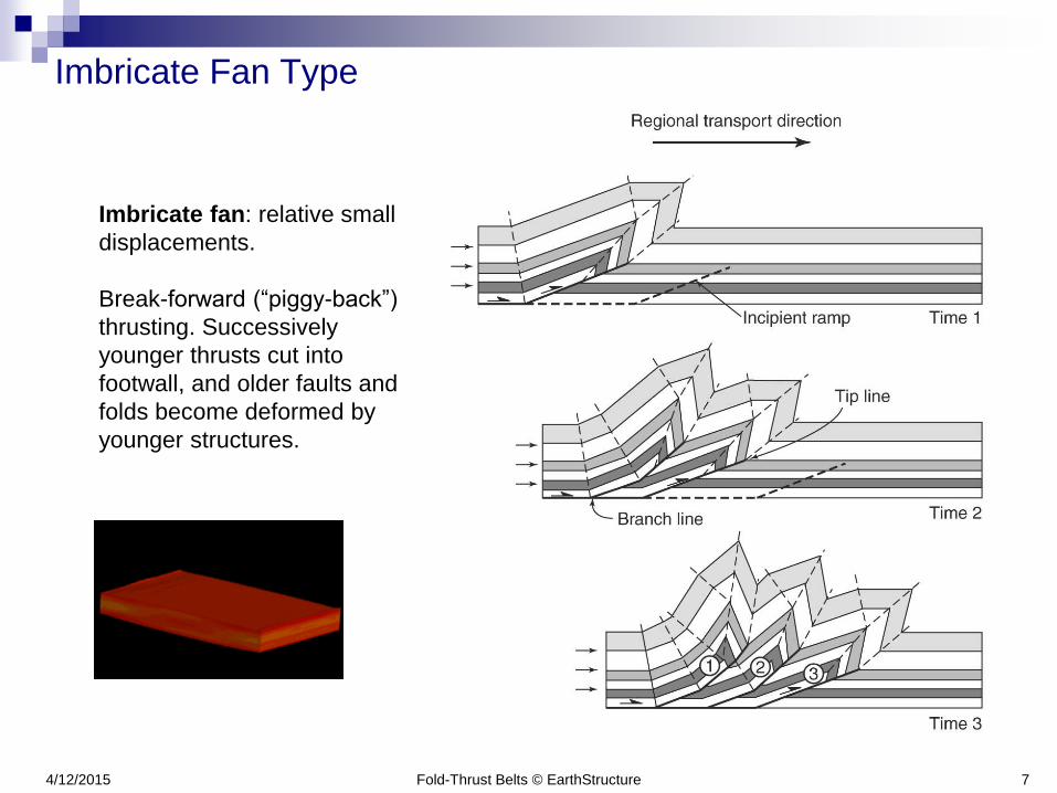
Imbricate Fan Type
Imbricate fan: relative small
displacements.
Break-forward (“piggy-back”)
thrusting. Successively
younger thrusts cut into
footwall, and older faults and
folds become deformed by
younger structures.
Fold-Thrust Belts © EarthStructure 84/12/2015
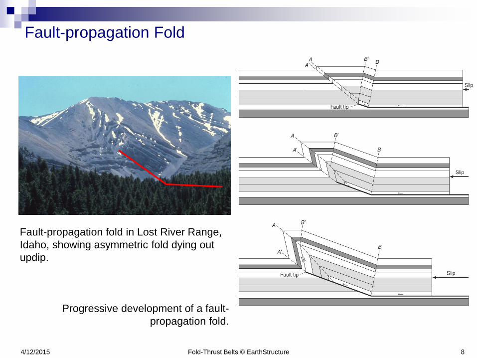
Fault-propagation Fold
Fault-propagation fold in Lost River Range,
Idaho, showing asymmetric fold dying out
updip.
Progressive development of a fault-
propagation fold.

Fold-Thrust Belts © EarthStructure 94/12/2015
Thrust Duplex Type
Duplex: relatively
large displacements.
Flat-roofed duplex
develops by
progressive break-
forward faulting.
Roof thrust
undergoes a
sequence of folding
and unfolding.
R. Allmendinger
Fold-Thrust Belts © EarthStructure 104/12/2015
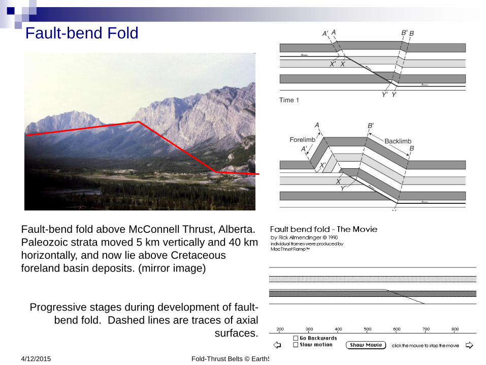
Fault-bend Fold
Fault-bend fold above McConnell Thrust, Alberta.
Paleozoic strata moved 5 km vertically and 40 km
horizontally, and now lie above Cretaceous
foreland basin deposits. (mirror image)
Progressive stages during development of fault-
bend fold. Dashed lines are traces of axial
surfaces.

Fold-Thrust Belts © EarthStructure 114/12/2015
Sevier Thrust belt

FTB Mechanics
Fold-Thrust Belts © EarthStructure 134/12/2015
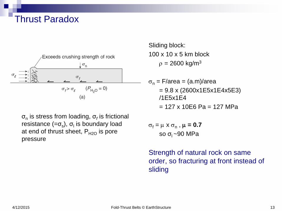
Thrust Paradox
Sliding block:
100 x 10 x 5 km block
r = 2600 kg/m3
sn = F/area = (a.m)/area
= 9.8 x (2600x1E5x1E4x5E3)
/1E5x1E4
= 127 x 10E6 Pa = 127 MPa
sf = m x sn , m = 0.7
so σl ~90 MPa
Strength of natural rock on same
order, so fracturing at front instead of
sliding
σn is stress from loading, σf is frictional
resistance (=σs), σl is boundary load
at end of thrust sheet, PH2O is pore
pressure
Fold-Thrust Belts © EarthStructure 144/12/2015
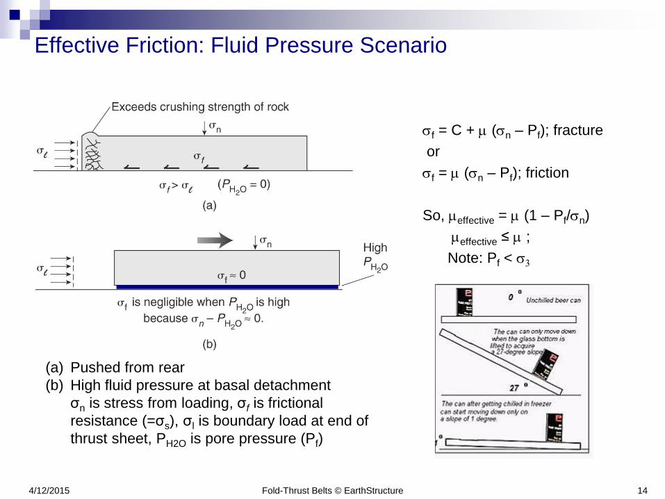
Effective Friction: Fluid Pressure Scenario
sf = C + m (sn – Pf); fracture
or
sf = m (sn – Pf); friction
So, meffective = m (1 – Pf/sn)
meffective ≤ m ;
Note: Pf < s3
(a) Pushed from rear
(b) High fluid pressure at basal detachment
σn is stress from loading, σf is frictional
resistance (=σs), σl is boundary load at end of
thrust sheet, PH2O is pore pressure (Pf)

Fold-Thrust Belts © EarthStructure 154/12/2015
Low Friction: Lubricant Scenario
(a) Pushed from rear
(b) Low friction material at basal detachment
σn is stress from loading, σf is frictional resistance, σl is boundary load at end of
thrust sheet
Low friction
material
Sliding block:
100 x 10 x 5 km block
r = 2600 kg/m3
sn = F/area = 127 MPa
sf = m x sn
m = 0.2, so σl ~25 MPa
Strength of natural rock
greater, so sliding

Fold-Thrust Belts © EarthStructure 164/12/2015
Gravity-driven: Sliding and Spreading
“Dry” sliding: dip is 35-40o (angle of repose)
“Wet” sliding: l = Pf/Pl
l = 1 (Pf=Plith), dip is ~0o
l = 0.8, dip ~10o
(a) Gravity Sliding. A block slides down foreland-tilted slope.
(b) Gravity sliding partly downslope and partly upslope.
(c) Gravity spreading. Before spreading, the wedge had shape indicated by
dashed line (“warm brie”).
Fold-Thrust Belts © EarthStructure 174/12/2015
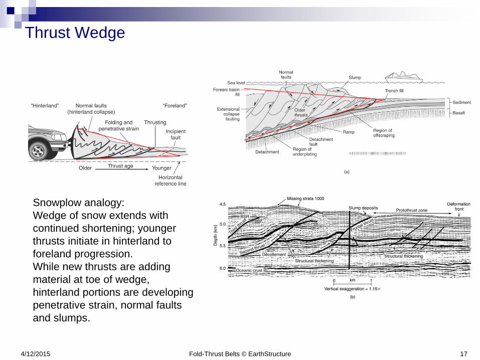
Thrust Wedge
Snowplow analogy:
Wedge of snow extends with
continued shortening; younger
thrusts initiate in hinterland to
foreland progression.
While new thrusts are adding
material at toe of wedge,
hinterland portions are developing
penetrative strain, normal faults
and slumps.

184/12/2015
Wedge Mechanics: Critical Taper Theory
Critical taper (angle φc) is sum of surface
slope angle (α1) and detachment slope
angle (β).
a) Stress acting on a wedge, partly
horizontal boundary load caused by
backstop (σbs) and partly caused by
gravity (σg).
b) If backstop moves, wedge thickens, so
surface slope increases, and taper (φ)
eventually exceeds φc.
c) Wedge slides toward foreland and new
material is added to toe, and extension
of wedge occurs so that surface slope
decreases.
φc

Example: Taiwan wedge
Fold-Thrust Belts © EarthStructure 194/12/2015
Critical taper (φc) is sum of surface
slope angle (α) and detachment slope
angle (β): 4.7o
F = meffective = st /sn = 0.1
(weak wedge)
Suppe, 2007