1.6 instrument cluster (ic) contentsmanual.startekinfo.com/volumes/ic1/1_6/content.pdf · oil level...
TRANSCRIPT

1.6 Instrument Cluster (IC) Contents ––––––––––––––––––––––––––––––––––––––––––––––––––––––––––––––––––––––––––––––––––––––––––––––––––––1.6 Model 202 up to 08/95
PageDiagnosisFunction Test . . . . . . . . . . . . . . . . . . . . . . . . . . . . . . . . . . . 11/1Complaint Related Diagnostic Chart . . . . . . . . . . . . . . . . . . . 12/1
Electrical Test Program Component Locations . . . . . . . . . . . . . . . . . . . . . . . . . . . . . 21/1Preparation for Test . . . . . . . . . . . . . . . . . . . . . . . . . . . . . . 22/1Test . . . . . . . . . . . . . . . . . . . . . . . . . . . . . . . . . . . . . . . . . 23/1
–––––––––––––––––––––––––––––––––––––––––––––––––––––––––––––––––––––––––––––––––––––––––––––––––––––––––––––––––––––––––––––––––––––––––––––––––––––––––––––––––––––––––––––––––––––––––––––––––––––––
b Diagnostic Manual • Information/Communication • 09/95 1.6 IC C/1
1.6 Instrument Cluster (IC) Model 202 up to 08/95 ––––––––––––––––––––––––––––––––––––––––––––––––––––––––––––––––––––––––––––––––––––––––––––––––––––Diagnosis – Function Test
General Information
Malfunction indicator/warning lamps
The instrument cluster is fully equipped with all lamps regardless ofactual vehicle equipment.
Bulb test
• Turn the ignition key to position “2”. All malfunction indicator/warninglamps must illuminate.
After 4 seconds, the SRS MIL will extinguish.After 30 seconds all other indicator/warning lamps will extinguish, withthe exception of the following: ABS, ASD or ASR, and generatorcharging lamps.
Start engine. At > 480 engine RPM, all indicator/warning lamps are toextinguish, indicating that all systems monitored are O.K.The indicator instruments must reflect the actual operating conditions.
a CAUTION!
Should the malfunction indicator/warning lamps remain illuminated and/orcome on while driving, it will be necessary to check the correspondingsystem with the Diagnostic Manual and/or the monitored fluid level asnecessary.
–––––––––––––––––––––––––––––––––––––––––––––––––––––––––––––––––––––––––––––––––––––––––––––––––––––––––––––––––––––––––––––––––––––––––––––––––––––––––––––––––––––––––––––––––––––––––––––––––––––––
b Diagnostic Manual • Information/Communication • 09/95 1.6 IC 11/1
1.6 Instrument Cluster (IC) Model 202 up to 08/95
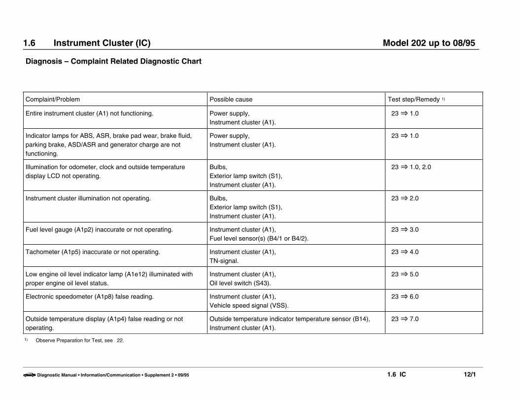
Diagnosis – Complaint Related Diagnostic Chart
Complaint/Problem Possible cause Test step/Remedy 1)
Entire instrument cluster (A1) not functioning. Power supply,Instrument cluster (A1).
23 O 1.0
Indicator lamps for ABS, ASR, brake pad wear, brake fluid,parking brake, ASD/ASR and generator charge are notfunctioning.
Power supply,Instrument cluster (A1).
23 O 1.0
Illumination for odometer, clock and outside temperaturedisplay LCD not operating.
Bulbs,Exterior lamp switch (S1),Instrument cluster (A1).
23 O 1.0, 2.0
Instrument cluster illumination not operating. Bulbs,Exterior lamp switch (S1),Instrument cluster (A1).
23 O 2.0
Fuel level gauge (A1p2) inaccurate or not operating. Instrument cluster (A1),Fuel level sensor(s) (B4/1 or B4/2).
23 O 3.0
Tachometer (A1p5) inaccurate or not operating. Instrument cluster (A1),TN-signal.
23 O 4.0
Low engine oil level indicator lamp (A1e12) illuminated withproper engine oil level status.
Instrument cluster (A1),Oil level switch (S43).
23 O 5.0
Electronic speedometer (A1p8) false reading. Instrument cluster (A1),Vehicle speed signal (VSS).
23 O 6.0
Outside temperature display (A1p4) false reading or notoperating.
Outside temperature indicator temperature sensor (B14), Instrument cluster (A1).
23 O 7.0
1) Observe Preparation for Test, see 22.
b Diagnostic Manual • Information/Communication • Supplement 2 • 09/95 1.6 IC 12/1

1.6 Instrument Cluster (IC) Model 202 up to 08/95
Diagnosis – Complaint Related Diagnostic Chart
Complaint/Problem Possible cause Test step/Remedy 1)
ECT gauge (A1p1) inaccurate or not operating. ECT gauge sensor (B13),Instrument cluster (A1).
23 O 8.0
Low ECL indicator lamp (A1e11) illuminated or notfunctioning.
ECL switch (S41),Instrument cluster (A1).
23 O 9.0
Low windshield washer fluid level indicator lamp (A1e13) illuminated or not functioning.
Windshield washer fluid level switch (S42),Instrument cluster (A1).
23 O 10.0
Brake pad wear indicator lamp (A1e6) illuminated or notfunctioning.
Brake pads,Left/right front brake pad wear sensor (S10/1 or S10/2),Instrument cluster (A1).
23 O 11.0
Low brake fluid level/parking brake indicator lamp (A1e7)illuminated or not functioning.
Brake fluid level switch (S11),Parking brake switch (S12),Instrument cluster (A1).
23 O 12.0
Generator charge indicator lamp (A1e5) illuminated or notfunctioning.
Generator (G2),Instrument cluster (A1).
23 O 13.0
SRS MIL (A1e15) not functioning. SRS control module (N2/2),Instrument cluster (A1).
23 O 14.0
ABS MIL (A1e17) not functioning. ABS control module (N30),Instrument cluster (A1).
23 O 15.0
ASD MIL (A1e24) not functioning. ASD control module (N30/2),Instrument cluster (A1).
23 O 16.0
ASR MIL (A1e22) not functioning. ASR control module (N30/1),Instrument cluster (A1).
23 O 17.0
1) Observe Preparation for Test, see 22.
b Diagnostic Manual • Information/Communication • Supplement 2 • 09/95 1.6 IC 12/2
1.6 Instrument Cluster (IC) Model 202 up to 08/95
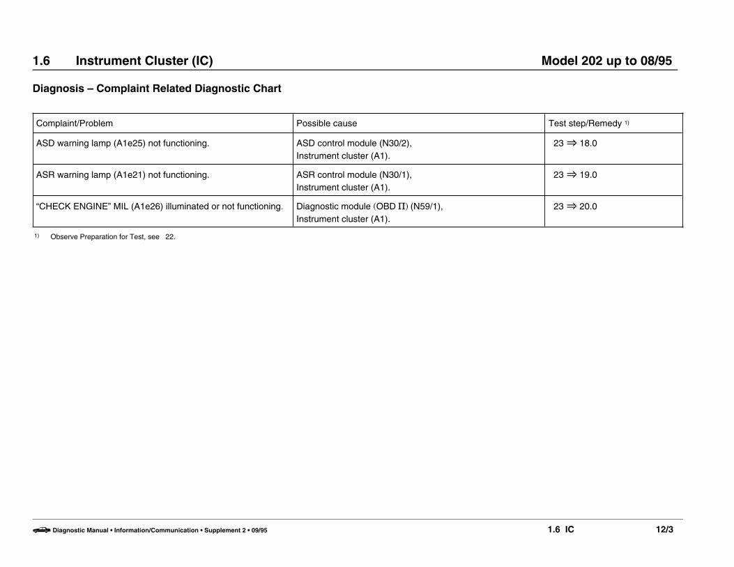
Diagnosis – Complaint Related Diagnostic Chart
Complaint/Problem Possible cause Test step/Remedy 1)
ASD warning lamp (A1e25) not functioning. ASD control module (N30/2),Instrument cluster (A1).
23 O 18.0
ASR warning lamp (A1e21) not functioning. ASR control module (N30/1),Instrument cluster (A1).
23 O 19.0
“CHECK ENGINE” MIL (A1e26) illuminated or not functioning. Diagnostic module (OBD S) (N59/1),Instrument cluster (A1).
23 O 20.0
1) Observe Preparation for Test, see 22.
b Diagnostic Manual • Information/Communication • Supplement 2 • 09/95 1.6 IC 12/3

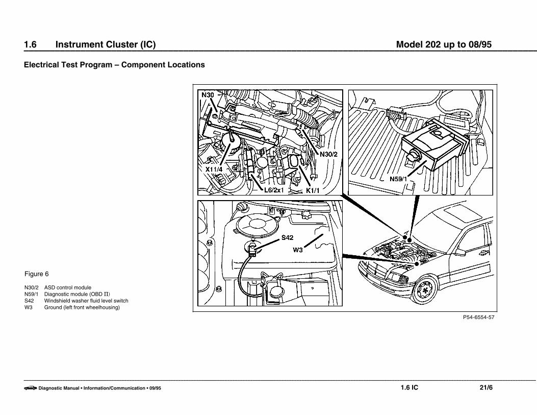
1.6 Instrument Cluster (IC) Model 202 up to 08/95 ––––––––––––––––––––––––––––––––––––––––––––––––––––––––––––––––––––––––––––––––––––––––––––––––––––Electrical Test Program – Component Locations
P54-6555-57
Figure 1
A1 Instrument clusterB14 Outside temperature indicator temperature sensorS43 Oil level sensor
–––––––––––––––––––––––––––––––––––––––––––––––––––––––––––––––––––––––––––––––––––––––––––––––––––––––––––––––––––––––––––––––––––––––––––––––––––––––––––––––––––––––––––––––––––––––––––––––––––––––
b Diagnostic Manual • Information/Communication • 09/95 1.6 IC 21/1

1.6 Instrument Cluster (IC) Model 202 up to 08/95 ––––––––––––––––––––––––––––––––––––––––––––––––––––––––––––––––––––––––––––––––––––––––––––––––––––
Electrical Test Program – Component Locations
P54-6095-57
Figure 2
S11 Brake fluid level switchS41 ECL switchX26/25 Engine/chassis connector (24-pole)
–––––––––––––––––––––––––––––––––––––––––––––––––––––––––––––––––––––––––––––––––––––––––––––––––––––––––––––––––––––––––––––––––––––––––––––––––––––––––––––––––––––––––––––––––––––––––––––––––––––––
b Diagnostic Manual • Information/Communication • 09/95 1.6 IC 21/2

1.6 Instrument Cluster (IC) Model 202 up to 08/95 ––––––––––––––––––––––––––––––––––––––––––––––––––––––––––––––––––––––––––––––––––––––––––––––––––––
Electrical Test Program – Component Locations
P54-6096-57
Figure 3
S10/1x1 Left front brake pad wear sensor connectorS10/2x1 Right front brake pad wear sensor connectorS12 Parking brake switch
–––––––––––––––––––––––––––––––––––––––––––––––––––––––––––––––––––––––––––––––––––––––––––––––––––––––––––––––––––––––––––––––––––––––––––––––––––––––––––––––––––––––––––––––––––––––––––––––––––––––
b Diagnostic Manual • Information/Communication • 09/95 1.6 IC 21/3

1.6 Instrument Cluster (IC) Model 202 up to 08/95 ––––––––––––––––––––––––––––––––––––––––––––––––––––––––––––––––––––––––––––––––––––––––––––––––––––
Electrical Test Program – Component Locations
P54-6097-57
Figure 4
N3/4 Engine control module (HFM-SFI)N30 ABS control moduleN30/1 ABS/ASR control moduleW16/6 Ground (component compartment - right)X11/4 Data link connector (DTC readout)
–––––––––––––––––––––––––––––––––––––––––––––––––––––––––––––––––––––––––––––––––––––––––––––––––––––––––––––––––––––––––––––––––––––––––––––––––––––––––––––––––––––––––––––––––––––––––––––––––––––––
b Diagnostic Manual • Information/Communication • 09/95 1.6 IC 21/4
1.6 Instrument Cluster (IC) Model 202 up to 08/95 ––––––––––––––––––––––––––––––––––––––––––––––––––––––––––––––––––––––––––––––––––––––––––––––––––––
Electrical Test Program – Component Locations
P54-6125-57
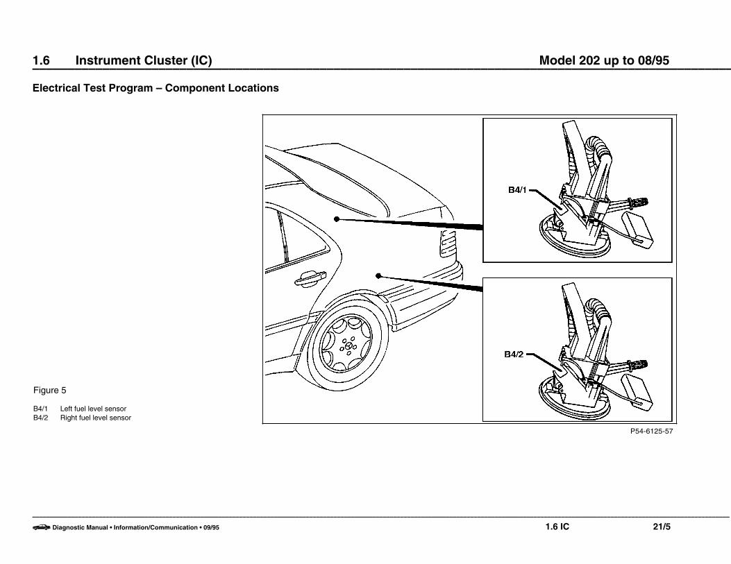
Figure 5
B4/1 Left fuel level sensorB4/2 Right fuel level sensor
–––––––––––––––––––––––––––––––––––––––––––––––––––––––––––––––––––––––––––––––––––––––––––––––––––––––––––––––––––––––––––––––––––––––––––––––––––––––––––––––––––––––––––––––––––––––––––––––––––––––
b Diagnostic Manual • Information/Communication • 09/95 1.6 IC 21/5
1.6 Instrument Cluster (IC) Model 202 up to 08/95 ––––––––––––––––––––––––––––––––––––––––––––––––––––––––––––––––––––––––––––––––––––––––––––––––––––
Electrical Test Program – Component Locations
P54-6554-57
Figure 6
N30/2 ASD control moduleN59/1 Diagnostic module (OBD S)S42 Windshield washer fluid level switchW3 Ground (left front wheelhousing)
–––––––––––––––––––––––––––––––––––––––––––––––––––––––––––––––––––––––––––––––––––––––––––––––––––––––––––––––––––––––––––––––––––––––––––––––––––––––––––––––––––––––––––––––––––––––––––––––––––––––
b Diagnostic Manual • Information/Communication • 09/95 1.6 IC 21/6
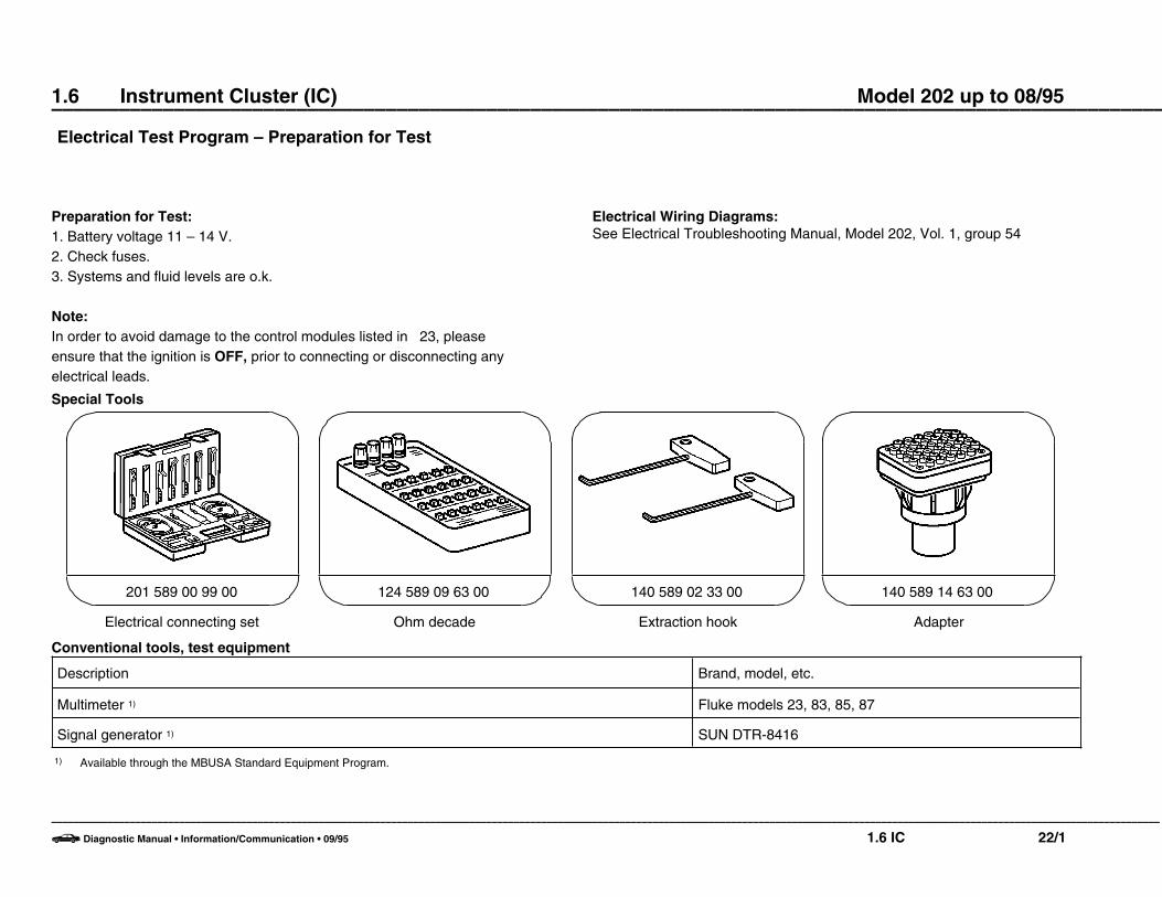
1.6 Instrument Cluster (IC) Model 202 up to 08/95 ––––––––––––––––––––––––––––––––––––––––––––––––––––––––––––––––––––––––––––––––––––––––––––––––––––Electrical Test Program – Preparation for Test
Preparation for Test:1. Battery voltage 11 – 14 V.2. Check fuses.3. Systems and fluid levels are o.k.
Note:In order to avoid damage to the control modules listed in 23, pleaseensure that the ignition is OFF, prior to connecting or disconnecting anyelectrical leads.
Electrical Wiring Diagrams:See Electrical Troubleshooting Manual, Model 202, Vol. 1, group 54
Special Tools
Electrical connecting set
201 589 00 99 00
Ohm decade
124 589 09 63 00
Extraction hook
140 589 02 33 00
Adapter
140 589 14 63 00
Conventional tools, test equipment
Description Brand, model, etc.
Multimeter 1) Fluke models 23, 83, 85, 87
Signal generator 1) SUN DTR-8416
1) Available through the MBUSA Standard Equipment Program.
–––––––––––––––––––––––––––––––––––––––––––––––––––––––––––––––––––––––––––––––––––––––––––––––––––––––––––––––––––––––––––––––––––––––––––––––––––––––––––––––––––––––––––––––––––––––––––––––––––––––
b Diagnostic Manual • Information/Communication • 09/95 1.6 IC 22/1
1.6 Instrument Cluster (IC) Model 202 up to 08/95
Electrical Test Program – Test
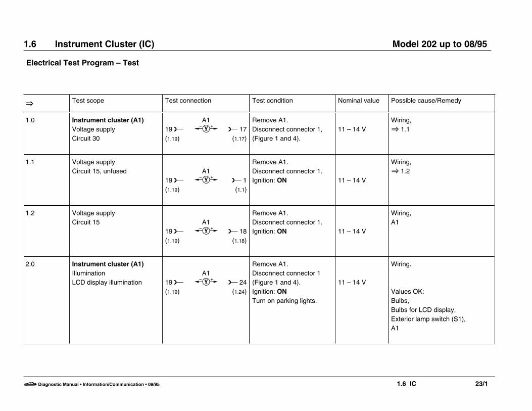
O Test scope Test connection Test condition Nominal value Possible cause/Remedy
1.0 Instrument cluster (A1)Voltage supplyCircuit 30
19 L(1.19)
A1c L 17
(1.17)
Remove A1.Disconnect connector 1,(Figure 1 and 4).
11 – 14 VWiring,O 1.1
1.1 Voltage supplyCircuit 15, unfused
19 L(1.19)
A1c L 1
(1.1)
Remove A1.Disconnect connector 1.Ignition: ON 11 – 14 V
Wiring,O 1.2
1.2 Voltage supplyCircuit 15
19 L(1.19)
A1c L 18
(1.18)
Remove A1.Disconnect connector 1.Ignition: ON 11 – 14 V
Wiring,A1
2.0 Instrument cluster (A1)IlluminationLCD display illumination 19 L
(1.19)
A1c L 24
(1.24)
Remove A1.Disconnect connector 1(Figure 1 and 4).Ignition: ONTurn on parking lights.
11 – 14 V
Wiring.
Values OK:Bulbs,Bulbs for LCD display,Exterior lamp switch (S1),A1
b Diagnostic Manual • Information/Communication • 09/95 1.6 IC 23/1

1.6 Instrument Cluster (IC) Model 202 up to 08/95
Electrical Test Program – Test
O Test scope Test connection Test condition Nominal value Possible cause/Remedy
3.0 Fuel level gauge (A1p2)Wiring and contacts 2
2 w
B4/1u
B4/2B
3
L 3
Ignition: OFFDisconnect connector ofleft fuel level sensor (B4/1)( 21, Figure 5).Jumper connect sockets,then remove connector forright fuel level sensor(B4/2) ( 21, Figure 5).Connect resistancesubstitution unit.Ignition: ONResistance substitutionunit setting:
8 +6 ]27 ± 5.3 ]
46.5 ± 10.5 ]96 ± 11.7 ]
145.5 ± 13.2 ]189 – 7.8 ]
Display in A1p2:
y 01)
y Res.1)
y 1/4y 1/2y 3/4y 1/1
Wiring,Instrument cluster (A1),O 3.1
[3.0] Vehicles (as of 03/94) withrecalibrated resistancevalues.
Resistance substitutionunit setting:
6 +6.6 ]24 ± 5.3 ]
51 ± 10.5 ]100.5 ± 11.7 ]145.5 ± 13.2 ]
189 – 7.8 ]
Display in A1p2:
y 01)
y Res.1)
y 1/4y 1/2y 3/4y 1/1
1) Fuel reserve warning lamp illuminates.
b Diagnostic Manual • Information/Communication • 09/95 1.6 IC 23/2

1.6 Instrument Cluster (IC) Model 202 up to 08/95
Electrical Test Program – Test
O Test scope Test connection Test condition Nominal value Possible cause/Remedy
3.1 Left fuel level sensor (B4/1).
Right fuel level sensor (B4/2).
2 v
2 v
B4/1b
B4/2b
K 3
K 3
Disconnect connector atB4/1.
Disconnect connector atB4/2.
3 (± 1) ] Empty97.5 (± 3) ] Full
3 (± 1) ] Empty97.5 (± 3) ] Full
B4/1
B4/2
4.0 Tachometer (A1p5)Wiring and contacts W16/6 y
X11/4L 17
Ignition: OFFDisconnect all connectorsfrom N3/4 ( 21, Figure4).
Connect signal generatorand set to a voltageamplitude of approx. 10 V(Figure 6).Ignition: ON
Engine 11130 Hz y1000/rpm130 Hz y4000/rpm200 Hz y6200/rpm
Engine 10450 Hz y1000/rpm195 Hz y4000/rpm315 Hz y6400/rpm
Wiring,Instrument cluster (A1).
Values OK:N3/4,Engine 104: D.M., Engines, Vol. 2– 1.1,Engine 111: D.M., Engines, Vol. 2– 1.2).
b Diagnostic Manual • Information/Communication • 09/95 1.6 IC 23/3

1.6 Instrument Cluster (IC) Model 202 up to 08/95
Electrical Test Program – Test
O Test scope Test connection Test condition Nominal value Possible cause/Remedy
5.0 Low engine oil levelindicator lamp (A1e12,Figure 2)Wiring and contacts
W3 uS43
1Oil level is OK.Disconnect connector fromoil level switch (S43).
Engine: at Idle A1e12 does notilluminate.
Wiring,S43,Instrument cluster (A1),O 5.1
5.1 Wiring and contacts Engine: at IdleDisconnect connector fromS43 ( 21, Figure 1).
A1e12illuminates after60± 10seconds.
A1e12,Wiring,A1,O 5.2
5.2W3 b
S43K 1 Connector unplugged at
S43.0 ]
S43.
b Diagnostic Manual • Information/Communication • 09/95 1.6 IC 23/4

1.6 Instrument Cluster (IC) Model 202 up to 08/95
Electrical Test Program – Test
O Test scope Test connection Test condition Nominal value Possible cause/Remedy
6.0 Electronic speedometer (A1p8)Wiring and contacts
Vehicles with ASR or ETSas of 06/94:Left front axle VSS sensor(L6/1) connected toASR/SPS or ETS/SPScontrol module (N47-1 orN47-2).See D.M., Chassis andDrivetrain, Vol. 3, 9.2 23
ABSW16/6
ABS/ASRW16/6
ASR/SPSorETS/SPSW16/6
y
y
y
N30L 5
(1.5)
N30/1L 18
(1.18)
N47-1N47-2
L
Ignition: OFFDisconnect connector fromABS control module (N30)or ASR control module(N30/1), ASR/SPS orETS/SPS control module(N47-1, N47-2) ( 21, Figure 4).
Connect signal generatorand set to a voltageamplitude of approx. 10 V(Figure 6).Ignition: ON
With increasingfrequence inputthe vehiclespeed indicatedmust alsoincrease.
Wiring,Instrument cluster (A1).
Values OK:N30 or N30/1,D.M., Chassis and Drivetrain,Vol. 2, 5.3 or 6.3 23
N47-1 or N47-2D.M., Chassis and Drivetrain,Vol. 3 – 9.2 23
b Diagnostic Manual • Information/Communication • 09/95 1.6 IC 23/5

1.6 Instrument Cluster (IC) Model 202 up to 08/95
Electrical Test Program – Test
O Test scope Test connection Test condition Nominal value Possible cause/Remedy
7.0 Outside temperatureindicator temperaturesensor (B14)( 21, Figure 1)Wiring and contacts
1 w(2.1)
A1b L 2
(2.2)
Remove A1.Disconnect connector 2(Figure 4).Measure ambient airtemperature at B14,( 21, Figure 1).
° F at B14– 4 ° F
+ 32 ° F+ 68 ° F
+ 104 ° F
y 29 k ]
y 9.8 k ]
y 3.7 k ]
y 1.6 k ]
Wiring,B14
Values OK: A1
8.0 ECT gauge (A1p1)Wiring and contacts W3 B
X26/25L 2
(B2)
Separate engine/chassisconnector (X26/25)( 21, Figure 2) andconnect in the resistancesubstitution unit.Ignition: ON
130 ]70 ]38 ]22 ]
Display (∞ C) inA1p1:
y 60 °Cy 80 °Cy 100 °Cy 120 °C
Wiring, A1
Values OK:ECT gauge sensor (B13).
b Diagnostic Manual • Information/Communication • 09/95 1.6 IC 23/6

1.6 Instrument Cluster (IC) Model 202 up to 08/95
Electrical Test Program – Test
O Test scope Test connection Test condition Nominal value Possible cause/Remedy
9.0 Low ECL indicator lamp (A1e11, Figure 2)Wiring and contacts
Disconnect connector atECL switch (S41) ( 21, Figure 2).Engine: at Idle A1e11 does not
illuminate.
Wiring, A1
Values OK: ECL switch (S41),O 9.1
9.1 Wiring and contacts1
S41u 2
Disconnect connector atS41 Engine: at Idle A1e11
illuminates afterapprox. 5 – 60sec.
A11e1,Wiring,A1
Values OK:S41
10.0 Low windshield washerfluid level indicator lamp(A1e13, Figure 2)Wiring and contacts
Disconnect connector atwindshield washer fluidlevel switch (S42) ( 21, Figure 6).
Engine: at Idle A1e13 doesnot illuminate.
Wiring,A1
Values OK:S42,O 10.1
b Diagnostic Manual • Information/Communication • 09/95 1.6 IC 23/7

1.6 Instrument Cluster (IC) Model 202 up to 08/95
Electrical Test Program – Test
O Test scope Test connection Test condition Nominal value Possible cause/Remedy
10.1 Wiring and contacts1
S42u 2
Disconnect connector atS42.
Engine: at Idle A1e13 illuminates.
A1e13,Wiring,A1
Values OK: S42
11.0 Brake pad wear indicatorlamp (A1e6, Figure 2)Wiring and contacts
Disconnect connector atleft front brake pad wearsensor connector(S10/1x1)( 21, Figure 3).Disconnect connector atright front brake pad wearsensor connector(S10/2x1)( 21, Figure 3).
Engine: at Idle
A1e6 does notilluminate.
Wiring,A1
Values OK: S10/1 or S10/2,O 11.1
b Diagnostic Manual • Information/Communication • 09/95 1.6 IC 23/8
1.6 Instrument Cluster (IC) Model 202 up to 08/95
Electrical Test Program – Test
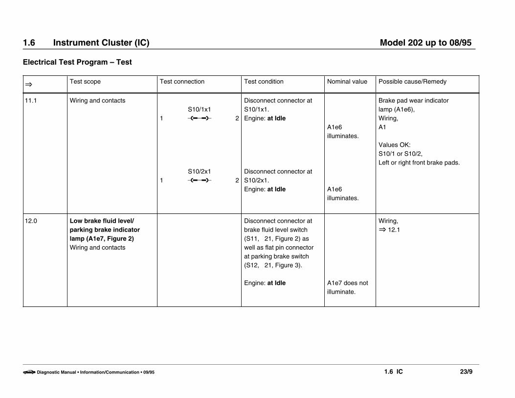
O Test scope Test connection Test condition Nominal value Possible cause/Remedy
11.1 Wiring and contacts
1
1
S10/1x1u
S10/2x1u
2
2
Disconnect connector atS10/1x1.Engine: at Idle
Disconnect connector atS10/2x1.Engine: at Idle
A1e6 illuminates.
A1e6 illuminates.
Brake pad wear indicator lamp (A1e6),Wiring,A1
Values OK:S10/1 or S10/2,Left or right front brake pads.
12.0 Low brake fluid level/parking brake indicator lamp (A1e7, Figure 2)Wiring and contacts
Disconnect connector atbrake fluid level switch(S11, 21, Figure 2) aswell as flat pin connectorat parking brake switch(S12, 21, Figure 3).
Engine: at Idle A1e7 does notilluminate.
Wiring,O 12.1
b Diagnostic Manual • Information/Communication • 09/95 1.6 IC 23/9
1.6 Instrument Cluster (IC) Model 202 up to 08/95
Electrical Test Program – Test
O Test scope Test connection Test condition Nominal value Possible cause/Remedy
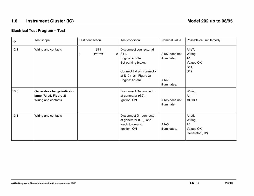
12.1 Wiring and contacts1
S11u 2
Disconnect connector atS11.Engine: at Idle Set parking brake.
Connect flat pin connectorat S12 ( 21, Figure 3)Engine: at Idle
A1e7 does notilluminate.
A1e7illuminates.
A1e7,Wiring,A1Values OK: S11,S12
13.0 Generator charge indicatorlamp (A1e5, Figure 3)Wiring and contacts
Disconnect D+ connectorat generator (G2).Ignition: ON A1e5 does not
illuminate.
Wiring,A1,O 13.1
13.1 Wiring and contacts Disconnect D+ connectorat generator (G2), andtouch to ground.Ignition: ON
A1e5illuminates.
A1e5,Wiring,A1Values OK: Generator (G2).
b Diagnostic Manual • Information/Communication • 09/95 1.6 IC 23/10

1.6 Instrument Cluster (IC) Model 202 up to 08/95
Electrical Test Program – Test
O Test scope Test connection Test condition Nominal value Possible cause/Remedy
14.0 SRS MIL (A1e15, Figure 3)Wiring and contacts
W16/6 uX11/4
30
Connect socket 30 of 38-pole data link connector(X11/4, Figure 6) to groundin right of componentcompartment (W16/6, 21, Figure 4).Engine: at Idle A1e15
illuminates.
A1e15,Wiring,A1Values OK: D.M., Body andAccessories, Vol. 3 – 16.3
15.0 ABS MIL (A1e17, Figure 3)Wiring and contacts
W16/6 uN30
29(1.29)
Ignition: OFFDisconnect connector atABS control module (N30, 21, Figure 4).Engine: at Idle A1e17
illuminates.
A1e17,Wiring,A1.
Values OK:D.M., Chassis and Drivetrain,Vol. 2 – 6.3
16.0 ASD MIL (A1e24, Figure 3)Wiring and contacts
W16/6 uN30/2
2(1.2)
Ignition: OFFDisconnect ASD controlmodule (N30/2) fromconnector ( 21, Figure 6).Engine: at Idle A1e24
illuminates.
A1e24,Wiring,A1
Values OK:D.M., Chassis and Drivetrain,Vol. 2 – 4.3
b Diagnostic Manual • Information/Communication • 09/95 1.6 IC 23/11

1.6 Instrument Cluster (IC) Model 202 up to 08/95
Electrical Test Program – Test
O Test scope Test connection Test condition Nominal value Possible cause/Remedy
17.0 ASR MIL (A1e22, Figure 3)Wiring and contacts
W16/6 uN30/1
10(1.10)
Ignition: OFFDisconnect connector fromASR control module(N30/1) ( 21 Figure 4).
Engine: at Idle A1e22illuminates.
A1e22,Wiring,A1
Values OK:D.M., Chassis and Drivetrain,Vol. 2 – 5.3
18.0 ASD warning lamp (A1e25)Wiring and contacts
W16/6 uN30/2
4(1.4)
Ignition: OFFDisconnect ASD controlmodule (N30/2) fromconnector ( 21, Figure 6).Engine: at Idle
A1e25illuminates.
A1e25,Wiring,A1
Values OK:D.M., Chassis and Drivetrain,Vol. 2 – 4.3
19.0 ASR warning lamp (A1e21)Wiring and contacts
W16/6 uN30/1
12(1.12)
Ignition: OFFDisconnect connector fromASR control module(N30/1) ( 21, Figure 4).Engine: at Idle A1e21
illuminates.
A1e21,Wiring,A1
Values OK: D.M., Chassis and Drivetrain,Vol. 2 – 5.3
b Diagnostic Manual • Information/Communication • 09/95 1.6 IC 23/12

1.6 Instrument Cluster (IC) Model 202 up to 08/95
Electrical Test Program – Test
O Test scope Test connection Test condition Nominal value Possible cause/Remedy
20.0 “CHECK ENGINE” MIL(A1e26, Figure 2)Wiring and contacts
Ignition: OFFDisconnect connector fromdiagnostic module (N59/1) ( 21, Figure 6).Engine: at Idle A1e26 does not
illuminate.
Wiring,O 20.1
20.1 Wiring and contacts
2N59/1
u 9
Ignition: OFFDisconnect connector fromN59/1 (Install bridge, Figure 5).Engine: at Idle A1e26
illuminates.
Wiring,A1,Diagnostic module (N59/1).
Values OK: D.M., Engines, Vol. 3 – 8.5
b Diagnostic Manual • Information/Communication • 09/95 1.6 IC 23/13

1.6 Instrument Cluster (IC) Model 202 up to 08/95
Electrical Test Program – Test
P54-6556-13
Figure 1
A1 Instrument cluster
P54-6506-13
Figure 3Indicator/warning lamps (right)1 Exterior lamp failure indicator lamp2 ASD or ASR MIL3 Generator charge indicator lamp4 SRS MIL5 Safety belt reminder lamp6 ABS MIL
P54-6505-13
Figure 2Indicator/warning lamps (left)1 Low ECL indicator lamp2 High beam indicator lamp3 Low brake fluid level and parking brake indicator lamp4 Brake pad wear indicator lamp5 Low engine oil level indicator lamp6 Low windshield washer fluid level indicator lamp7 “CHECK ENGINE ” MIL
b Diagnostic Manual • Information/Communication • 09/95 1.6 IC 23/14

1.6 Instrument Cluster (IC) Model 202 up to 08/95
Electrical Test Program – Test
P54-6089-13
Figure 4
A1 Instrument cluster1 Connector (24-pole)2 Connector (21-pole)
P54-6553-13
Figure 5
N59/1 Diagnostic module (OBD S)
b Diagnostic Manual • Information/Communication • 09/95 1.6 IC 23/15

1.6 Instrument Cluster (IC) Model 202 up to 08/95
Electrical Test Program – Test
P54-6692-57
Figure 6
5a ABS control module connector, socket 517 Data link connector, 38-pole (X11/4), socket 1718 ASR control module connector, socket 1830 Data link connector, 38-pole (X11/4), socket 30
b Diagnostic Manual • Information/Communication • 09/95 1.6 IC 23/16