170508 giz-santa rosa final report rosa_lo… · title: microsoft word - 170508_giz-santa rosa...
TRANSCRIPT

Low-Income Housing in Santa Rosa, Philippines Design Proposal for Improving Natural Venti lation and Cost Efficient Construction
Martin Schoch, Ph.D. | Unexpected Co., Ltd. [email protected]
Final Report
April 2017

FINAL REPORT
Unexpected Co., Ltd. Page 1 of 64
CONTENTS Contents .................................................................................................................................................. 1
Figures ..................................................................................................................................................... 2
Executive Summary ................................................................................................................................. 4
Introduction ............................................................................................................................................ 5
Santa Rosa ........................................................................................................................................... 5
Location ........................................................................................................................................... 5
Climate ............................................................................................................................................ 7
Geography ....................................................................................................................................... 9
Population ..................................................................................................................................... 10
Low Cost Housing project ............................................................................................................. 10
Scope of Work ................................................................................................................................... 11
Expected result ................................................................................................................................. 12
Analysis ................................................................................................................................................. 13
Existing design ................................................................................................................................... 13
Environmental and Economic design Measures ................................................................................... 15
Environmental context...................................................................................................................... 15
Climate Responsive Design Measures .......................................................................................... 15
Economic Context ............................................................................................................................. 17
‘Low Cost’ Buildings ...................................................................................................................... 17
Commonly Practiced Building technology .................................................................................... 18
Modular Block System ................................................................................................................. 19
Ripped Slap System ...................................................................................................................... 20
Alternative Schematic Designs .............................................................................................................. 21
Scheme A .......................................................................................................................................... 21
Site Layout ..................................................................................................................................... 22
Building Layout .............................................................................................................................. 24
Unit Design .................................................................................................................................... 25
Scheme B ........................................................................................................................................... 27
Site Layout ..................................................................................................................................... 28
Building Layout .............................................................................................................................. 29
Unit Design .................................................................................................................................... 31
Finalization of Architectural Design ...................................................................................................... 32

FINAL REPORT
Unexpected Co., Ltd. Page 2 of 64
Suggestions and Comments .............................................................................................................. 32
Final Scheme Drawings ..................................................................................................................... 35
Site Layout ..................................................................................................................................... 35
Building Layout .............................................................................................................................. 36
Unit Design .................................................................................................................................... 38
Summary and Recommendation .......................................................................................................... 39
Results Summary............................................................................................................................... 39
Environmental Measures .............................................................................................................. 39
Economical Measures ................................................................................................................... 39
Recommendation .............................................................................................................................. 39
Appendix ............................................................................................................................................... 40
Drawing Documents PRE-DESIGN ..................................................................................................... 40
Final Design Complete Drawing Documentation .............................................................................. 42
Building Type A – Housing for Government Employee ................................................................. 42
Building Type B – Housing for Informal Settler ............................................................................. 53
FIGURES Figure 1: Geographic location of Santa Rosa, Philippines ....................................................................... 5
Figure 2: Geographic location of Site in Barangay Labas of Santa Rosa City, Philippines ...................... 6
Figure 3: Aerial view of Site Area ............................................................................................................ 6
Figure 4: Santa Rosa Laguna / Annual Max., Min and Average Temperate (Celsius Degrees/ 2016) .... 7
Figure 5: Santa Rosa, Laguna / Cloudy Days, and Humidity Levels per month (2016) ........................... 8
Figure 6: Santa Rosa Laguna / Average and Max Wind Speed and Gust (mph) ..................................... 8
Figure 7: Santa Rosa, Laguna / Average Rainfall Amount (mm) and rainy days ..................................... 9
Figure 8: Population of Santa Rosa (1990-2015) .................................................................................. 10
Figure 9: Existing Design, Overview Land Use ...................................................................................... 13
Figure 10: Bioclimatic Chart for Santa Rosa (Manila Airport weather station) .................................... 15
Figure 11 Annual Wind directions and strength for Santa Rosa (Manila Airport weather station) ..... 16
Figure 12: Philippines Maximum (Blue), Average (Black) Construction Cost & Tendency (Orange)
between 2008-2016 .............................................................................................................................. 17
Figure 13: Average Construction Cost (2016, Monthly Frequency)...................................................... 17
Figure 14: Product Data Sheet Modular Block System ......................................................................... 19

FINAL REPORT
Unexpected Co., Ltd. Page 3 of 64
Figure 15: Product Data Sheet Ripped Slap System .............................................................................. 20
Figure 16: Scheme A - Masterplan ........................................................................................................ 22
Figure 17: Scheme A – Vizualiation Site View ....................................................................................... 23
Figure 18: Scheme A - Overview Land Use ........................................................................................... 23
Figure 19: Scheme A - Building layout and orientation ........................................................................ 24
Figure 20: Scheme A - Floor Plan Layout for building of Government Employees ............................... 24
Figure 21: Scheme A - Floor Plan Layout for building of Informal Settlers ........................................... 25 Figure 22: Scheme A - Floor Plan Layout of Apartment for Government Employees [33 sqm] ........... 25 Figure 23: Scheme A - Floor Plan Layout of apartments for Informal Settlers [24 sqm] ...................... 26 Figure 24: Scheme B - Masterplan ........................................................................................................ 28 Figure 25: Scheme B – Visualisation Site View ..................................................................................... 29 Figure 26: Scheme B - Overview Suggested Land Use .......................................................................... 29 Figure 27: Scheme B - Building layout and orientation ........................................................................ 29 Figure 28: Scheme B - Floor Plan Layout for building of Government Employees ............................... 30 Figure 29: Scheme B - Floor Plan Layout for building of Informal Settlers ........................................... 30 Figure 30: Scheme B - Floor Plan Layout of Apartment for Government Employees [33 sqm] ........... 31 Figure 31: Scheme B - Floor Plan Layout of apartments for Informal Settlers [24 sqm] ...................... 31 Figure 32: Final Design - Overview Suggested Land Use ...................................................................... 33 Figure 33 Final Design - Masterplan ..................................................................................................... 35 Figure 34: Final Design - Building Type A for Government Employees - Floor Plan Layout First Floor 36 Figure 35: Final Design - Building Type B for Informal Settler - Floor Plan Layout First Floor .............. 37 Figure 36: Final Design - Building Type A for Government Employees – Apartment Unit - Floor Plan Layout.................................................................................................................................................... 38 Figure 37: Final Design - Building Type B for Informal Settler – Apartment Unit - Floor Plan Layout .. 38

FINAL REPORT
Unexpected Co., Ltd. Page 4 of 64
EXECUTIVE SUMMARY Santa Rosa, in the province of Laguna, Philippines, is one of the Nexus partner cities within the “Integrated Resource Management in Asian Cities: The Urban Nexus” project, financed by the German Federal Ministry of Economic Cooperation and Development (BMZ) and implemented by Deutsche Gesellschaft für Internationale Zusammenarbeit (GIZ) GmbH’.
The City of Santa Rosa has requested design assistance from GIZ Urban Nexus Project to conduct a study on the design for a low-income housing project for the accommodation of government employees, and informal settlers. The studies objective is to create an architectural design of multi-residential apartment buildings in reference to an existing site under the authority of the City of Santa Rosa, emphasizing on finding suitable measures in respect to environmental and economic regards.
A study was undertaken, firstly, on the inquiry of a preliminary design scheme provided the City of Santa Rosa, and secondly, on the consideration of appropriate environmental and economic design measures regarding the local context. With understanding attained, two alternative design were proposed for deliberation and discussion with project stakeholders about environmental concerns such as and cost efficiency. Based on suggestions and comments made, one scheme was selected for development.
The final design suggests that environmental improvement can be achieved when considering building orientation, shading, natural ventilation, and flooding hazard protection. Regarding economic measures, cost efficiency can be improved by focusing on design simplification, locally practiced construction techniques and use of commonly available building materials.

FINAL REPORT
Unexpected Co., Ltd. Page 5 of 64
INTRODUCTION SANTA ROSA The city of Santa Rosa is situated in the province of Laguna, Philippines. The city is predominantly a suburban residential community of Metro Manila in the western section of Laguna de Bay (Figure 1). It lies 38 kilometers south of Manila’s Ninoy Aquino International Airport, connected via the South Luzon Expressway.
With a land area of approximately 54.13 square kilometers, it is the second largest local government unit in Laguna de Bay. Santa Rosa City is governed by its city mayor as the chief executive of the city, the vice mayor, and the city councilors that acts as its legislative body. The legislative body is composed of 10 regular members and representatives from the barangays (city districts) and a youth council. The western part of Santa Rosa allocates several commercial, industrial, and business areas. To the North, the city is mainly occupied by residential areas and subdivisions, schools, industrial zones, and various businesses.
Figure 1: Geographic location of Santa Rosa, Philippines
LOCATION The site for the Low-Income Housing Complex is situated in Barangay Labas of Santa Rosa City, located nearby Rizal Boulevard train station, about 400 meters from the Santa Rosa City Hall, and about 600 meters Northeast of the shores of Laguna Bay.
It is currently accessible from the South via Masiit Road using all common vehicles types. The site is bound on the south by private residential houses, on the North and East by rice fields and on the west by a private subdivision of residential area that is currently under construction.
The location can be found with the web-based Google map application under the geographic coordinates of 14°18'17.6"North / 121°06'27.0"East. The following map in figure 2 illustrates the geographic location of the project site, and figure 4 provides and aerial view of it.
Santa Rosa
Manila

FINAL REPORT
Unexpected Co., Ltd. Page 6 of 64
Figure 2: Geographic location of Site in Barangay Labas of Santa Rosa City, Philippines
Figure 3: Aerial view of Site Area1
The proposed site for the low-cost housing development covers a total land area of 22,147 square meters. The property is currently unbuilt. It foresees land use conversion of its former agricultural land to residential use as part of a continuous densification in the area. Due to increased housing demand, private housing estate developments of low-rise housings are currently being realized along the East side of the property. All existing buildings, as well as the currently planned residences in the neighborhood, do not cast shadows onto the site during the day.
1 ‘Google Maps’ satellite image
Site location
Site location

FINAL REPORT
Unexpected Co., Ltd. Page 7 of 64
CLIMATE The local climate is understood as tropical, characterized by high average outdoor temperature and continuously high humidity levels throughout the year. According to Köppen’s climate classification, Santa Rosa’s climate is understood as ‘tropical monsoon’ (Am) with two pronounced seasons: a ‘dry’ season from January to April, and a ‘wet’ season from May to December. Accordingly, the driest month of the year is March, when the Northeast monsoon prevails in the Eastern parts of the Philippines. October has the highest mean rainfall; with the Southwest monsoon bringing precipitations through heavy rainfalls, local thunderstorms, or typhoons. November to February are the coolest months, while April to June are the hottest months.
Sun Exposure Located near the equatorial belt, sun radiation is high throughout the year. With a global horizontal radiation of up to 780 Wh/sqm, buildings must consider appropriate shading, especially during mid-day to afternoon hours along South and West building orientations.
Temperature and Humidity Information on the local climate condition has been retrieved several internet data bases2, 3. The cities mean annual temperature is 27.6 ºC and is considered as relatively cool due to the cities elevation and favorable airshed condition. The warmest month is May with an average of 30.0 ºC while the coolest month is January with an average temperature of 25.0 ºC4. Figure 5 illustrates the monthly recorded high, low and mean temperatures in Santa Rosa during 2016.
Figure 4: Santa Rosa Laguna / Annual Max., Min and Average Temperate (Celsius Degrees/ 2016)
Average relative humidity is roughly 80% in Santa Rosa, making the city somewhat cooler than the Metropolitan area of Manila with an average relative humidity of 81%. Figure 6 illustrates the
2 World Weather Online (http://worldweatheronline.com) 3 ClimateData.Org (http://en.climate-data.org) 4 City of Santa Rosa, ( http://santarosacity.gov.ph/about-sta-rosa/climate/)

FINAL REPORT
Unexpected Co., Ltd. Page 8 of 64
monthly recorded humidity levels and the amount of cloudy days in percentages in Santa Rosa during 2016.
Figure 5: Santa Rosa, Laguna / Cloudy Days, and Humidity Levels per month (2016)
Wind Speed and Direction Northeasterly winds prevail during the months of October through February. Winds come from the Southeast during March and April. Southerly winds prevail during May while from June through September. The average speed of winds is 5 kilometres per hour.
Figure 6: Santa Rosa Laguna / Average and Max Wind Speed and Gust (mph)

FINAL REPORT
Unexpected Co., Ltd. Page 9 of 64
Precipitation and Rainfall Intensity The annual average rainfall is about 1,950 millimeters. The maximum rainfall occurs in October while minimum rainfall is measured about 10 millimeters at the beginning of the year. Though the municipality is located in a region where typhoons occur, Santa Rosa is hardly affected due to its surrounding mountain areas. The following figure 8 provides an overview over local precipitation amount in 2016.
Figure 7: Santa Rosa, Laguna / Average Rainfall Amount (mm) and rainy days
GEOGRAPHY According to a conducted geohazard assessment 5, the foreseen site can be considered being within low to medium risk zone regarding earthquakes and flooding. Considering its distance from the active earthquake generating structures, the site could be considered suitable for development. However, proper design and engineering of the building including choice of good quality construction material must be strictly implemented.
Earthquakes The site location is within the classified residential district of the approved City Zoning of Santa Rosa. Yet, lying close to several active earthquake generators, earthquakes resulting from fault movements are an unavoidable and unpredictable phenomenon the place could experience. Located on a flat terrain, with underlying of layers of unconsolidated soils and sediments, building foundations must lie on hard ground formation to avoid soil settlement.
Flooding The project is located on flat terrain with an elevation of ±7 meters above sea level and falls under moderate to high susceptibility to flooding by Mines and Geosciences Bureau. Elevating the project site may lessen its susceptibility to flooding. Maintenance and cleaning of drainage systems not only in the project site but also in the main drainage outlet should be given full consideration by the home
5 Geohazard Assessment Report, Hernani I. Bayani

FINAL REPORT
Unexpected Co., Ltd. Page 10 of 64
owners/developer to prevent increase siltation, and clogging of waterways which, will eventually lead to localized flooding.
Urbanization Continuous urbanization in this part of the region resulted in the near depletion of tropical rainforest in mountainous areas and low-lying plains. In these areas, only limited varieties of small diameter trees abound along the upstream banks of the major rivers and tributaries of the highlands. At present, around seventy percent of the low-lying areas occupied are by residential houses, commercial and industrial establishments and rest are covered with agriculturally used land.6 The transformation from agricultural land into urbanized areas are continuing.
POPULATION According to Philippine Statistics Authority, the city’s population record stated 353,767 inhabitants in 2015. The population of Santa Rosa is fast-growing, over the last 25 years its growth rates were between 2.4-7.3%.
Year Population ±% p.a. 1990 94,719 — 1995 138,257 +7.34% 2000 185,633 +6.52% 2007 266,943 +5.14% 2010 284,670 +2.37% 2015 353,767 +4.22%
Figure 8: Population of Santa Rosa (1990-2015)7
Santa Rosa’s population density averaged of 1,749 and 3,351 persons per square kilometer of land area in the year 1990 and 2000 respectively8. In 2012, Santa Rosa had a population density of 5,226 persons per square kilometer of land area, reaching a population density comparable to Bangkok with around 5,300/km2.
LOW COST HOUSING PROJECT It is assumed that the evolving status of Santa Rosa as the location of middle to high-class developments will further add to the increase in population. This means that, as the population of the city continuously increases, the competition for the demand of commodities like land will increase as well.9 A present aim of the city is thus to ensure sufficient affordable housing possibilities for citizens with lower incomes, particularly in respect to the number of low-income government employees in Santa Rosa currently in need for proper accommodations.
In addition, many informal settlers, allocating their shanties along riverbanks and unoccupied land stretches, are of concern to the city. Not only are the location of their illicit settlements considered as high risk areas that are vulnerable to flooding, they also face significant water pollution from solid and liquid (sewage) wastes from the settlers and communities nearby.
The city is considering to support the realization of ‘multi-story apartment-style’ residences for informal settlers and government employees (ownership of the property) in such a way that it would fit the financial capacities of the beneficiaries with consideration to the standards set by the National
6 Geohazard Assessment Report, Hernani I. Bayani 7 Source: Philippine Statistics Authority 8 Philippine Statistics Authority 9 City of Santa Rosa, ( http://santarosacity.gov.ph/about-sta-rosa/climate/)

FINAL REPORT
Unexpected Co., Ltd. Page 11 of 64
Housing Authority. However, intensive education maybe necessary for the adoption of the ‘new’ community with the integration of the nexus approach10.
Yet, another consideration is the investment of a vacuum sewer system for the planned housing project to prevent soil and groundwater pollution from leaching sewage of traditional septic tanks. It is anticipated that such would not only require training of the engineering staff for the operation and maintenance of the system, but also a general mind-shift of the informal settlers; i.e. willingness to embrace new ways of living and system technology (vacuum system)5. According to studies of the local Nexus team, expected benefits of a resettlement of informal settlers and use of a vacuum sewer system are as follows:
Transfer of informal settlers from high risk / flood-prone areas to safe and environmentally-sound and sustainable community
Pollution decrease of surface waters/river systems caused by indiscriminate throwing of garbage and direct discharge of sewage into water bodies.
Reduce water consumption from toilet flushing (vacuum sewer system use less water as compared to manual or automatic toilet flushing).
Reduced environmental and health risks from contaminated groundwater and polluted rivers
Considerable savings in construction costs of the vacuum sewer system.
SCOPE OF WORK The “Integrated Resource Management in Asian Cities: The Urban Nexus” implemented by GIZ is consulting a new building project for a multi residential low-cost housing in Santa Rosa, Philippines. The project owner is the City of Santa Rosa, with its building department as planning team of the project.
Per provided Terms of References of the GIZ Nexus Project, the scope of work of this study is to collaborate in the planning and implementation of an environmentally friendly low-cost housing project for government employees of the city and informal settlers. At the beginning of the consultation in January 2017, a preliminary design of the project, including a masterplan and designs of two building types were provided. Unexpected Co., Ltd. was asked to evaluate the design proposal and offer an architectural design solution considering environmental and economic improvement.
Divided into the following steps, the suggested work phases are described as follows:
- Analysis of existing preliminary design - Review on suitable environmental and economic design measures - Schematic Design
- Proposal of two alternative schemes including a Masterplan, building design plans and apartment designs
- Presentation to the Authorities at the City Hall of Santa Rosa and GIZ. Discussion, and consideration of comments and suggestions for inclusion into the final design scheme for the entire site as well as for the individual buildings.
- Final Design - Preparation of drawings set of architectural design scheme including:
Building floor plans, building sections and elevations, apartment units’ floor plan,
10 Erlinda C. Creencia, Urban Nexus Project, City of Santa Rosa

FINAL REPORT
Unexpected Co., Ltd. Page 12 of 64
Preparation of Master-plan including buildings, street -, and landscaping on the entire property.
Suggestive layout planning for waste water system per new architectural design scheme.
3D views of buildings - Summary and Recommendation
EXPECTED RESULT It is expected that the collaborative study is leading to the development of an architectural design solution to improves the addressed environmental and economic design measures progressively by creating:
A. Well developed, yet affordable housing units to their future owners B. Sustainable building construction solution considering material use, as well as appropriate
construction technique C. An environmentally responsive design solution considering the climatic context of the site. D. Pleasant yet functional outdoor environment.

FINAL REPORT
Unexpected Co., Ltd. Page 13 of 64
ANALYSIS EXISTING DESIGN An existing preliminary design has been provided for the inquiry of usage and function, building operation, selection of construction method and selection of materials based on provided planning documents.
The current design, provided by the City of Santa Rosa, foresees about 312 (13x6x4) units for government employees, and 304 (19x4x4) units for informal settlers with a total of 45,166 sqm floor area that are distributed over 10 buildings with five floor levels each. There are two building types; one that foresees the apartment units of 33 sqm for government employees and, a second that provides for the apartment units of 24 sqm designated informal settlers. The separation into two different building types for the two resident types is intended to avoid later conflicts between them.
In the Masterplan, one main access road, crossing the property from South to North, is connecting the land to the existing road infrastructure. All buildings are situated alongside that road, making the buildings orientation to be primarily towards North - South orientation. This means that the elongated façades of the buildings are exposed towards East - West orientation. Between some buildings, a total of 48 (3*16) parking spaces and two multipurpose outdoor areas are foreseen. Further, a vacuum sewage system, has already been considered and a location for a building unit that houses the sewage pumps allocated on the masterplan.
The two building types for government employees and informal settlers are similar in their overall appearance, with a L-shaped floor plan layout and a centralized corridor to accesses the individual housing units. The first-floor level of the building units remains unbuilt, with the allocation of the residential units starting from the second floor upwards. Currently no additional functions, such as are garbage collection or technical areas are foreseen.
The overview of the properties calculated land use is shown in figure 5, with the data is taken from provided drawing documents. It should be noted that the area of the unutilized first floor level was not included in the gross floor area calculation.
Type Area [m2] Percentage
Property Size 22,147.00
Gross Floor Area (All Floors) 45,166.00 100.0%
Footprint Area (1st Floor) 11291.50 25.0%
Buildings Government Employees 16,929.00 37.4%
Buildings Informal Settlers 12,420.53 27.5%
Green + Parking 10,688.00 23.66%
Road 4,245.00 9.4%
Sewer 884.00 1.7%
Figure 9: Existing Design, Overview Land Use
With a total amount of 616 apartment units the settlement must be considered as high density, making it vulnerable to social conflicts. Considering an average amount of 3 residents per apartment unit, a total of 1,848 people, or a population density of approx. 82,000 p/km2, respectively is to be

FINAL REPORT
Unexpected Co., Ltd. Page 14 of 64
assumed. Focusing on environmental and economic condition of the design, several qualitative design judgements were made to help understanding the designs baseline condition and its potential for improvement.
In the following positive and negatives remarks have been listed per their expected environmental impact:
Separation into building types avoid social conflict Centralized corridors minimize infrastructure
- Building orientation is disadvantage due to sun path exposing large amounts of the building
facades towards East and West - Natural ventilation of corridor paces units does not seem supported - Natural ventilation of individual apartment units does not seem supported - Position of bath rooms do not allow for adequate ventilation - Bathroom position make units inflexible in terms of usage
Considering cost for building construction, the following positive and negative have been identified:
Rectangular, simple building designs Repetitive apartment units Repetitive floor levels
- Amount of vertical staircases - Pathways (bridges) between neighboring buildings - Increased buildable floor area (unutilized 1st floor level) - Increased construction effort due to empty 1st floor level - Increased amount of installation shafts due to separate allocation of plumbing fixtures

FINAL REPORT
Unexpected Co., Ltd. Page 15 of 64
ENVIRONMENTAL AND ECONOMIC DESIGN MEASURES ENVIRONMENTAL CONTEXT CLIMATE RESPONSIVE DESIGN MEASURES In combination with existing weather data, general suggestive design strategies for the buildings design can be deducted using a bioclimatic chart and respective zone definitions. The bioclimatic chart in figure x illustrates existing temperature / humidity levels (green dots) in relation to the climatic comfort zone (blue polygon).
Figure 10: Bioclimatic Chart11 for Santa Rosa (Manila Airport weather station)
Accordingly, climatization by predominantly using cooling and dehumidification is essential throughout the year. Additionally, sun shading (green polygon) and fan forced ventilation cooling (orange polygon) is supportive when temperature/humidity levels are close to comfort zone levels. In response to the design strategies that were retrieved from the bioclimatic chart, appropriate measures for building designs were deducted that were define as follows with the tagged measures deeming suitable for the specific housing project:
Good natural ventilation can help eliminate air conditioning in warm weather if windows are well shaded and oriented toward prevailing breezes
Building sizes should remain small as excessive floor areas increase cooling energy demand
Long narrow floorplans can help maximize cross ventilation in hot humid climates Use of plant materials around the buildings and/or on building facades (trees, bushes,
ivy covered walls), especially on the West to minimize heat gains × Radiant barriers, such as reflective coating help reducing radiant heat gain through
the roof Buildings raised above the ground help to avoid dampness and maximize natural
ventilation × high performance (low E, insulated frames) glazing to reduce solar heat gains
11 Source: ‘Climate Consultant’ software, version 6.1

FINAL REPORT
Unexpected Co., Ltd. Page 16 of 64
Minimize or eliminate west glazing to reduce solar heat gain in afternoon hours Operating cooling temperature adjustment according to building usage Facilitate cross ventilation, locate doors and windows on opposite sides of buildings
with larger windows facing upwind if possible Window overhangs or operable sunshades can reduce air conditioning × Raise indoor set point temperature of indoor air-conditioning to reduce air
conditioning consumption On hot days, ceiling fans and indoor air movement can make it seem cooler by 2-3
degrees Celsius or more. Thus, less AC is needed Use light colored building materials and cool roof with high emissivity to minimize
conductive heat gains Screened porches and patios can provide passive comfort cooling by ventilation in
warm weather Orient most glass to the North, shaded by vertical fins, because there are essentially
no passive solar needs Warm humid climates have openings protected by overhangs and verandas Passive homes in hot climates use light weight constructions openable walls and
shaded outdoor porches, raised above ground.
With natural ventilation being a possible, cost efficient way of reducing the need for cooling, the following chart in figure x illustrates the existing annual wind directions and strength as measured in relative distance to the site. The graphic indicates that winds primarily blow in East to West and West to East direction.
Figure 11 Annual Wind directions and strength for Santa Rosa (Manila Airport weather station)
Natural ventilation for buildings or building units can be realized when allowing for cross or stack ventilation. Cross ventilation occurs when existing exterior winds are channeled through interior spaces, thus ideally requiring for entry, and exit points. In case wind directions lead directly towards
FINAL REPORT
Unexpected Co., Ltd. Page 17 of 64
the openings cross ventilation can be realized more easily. If not, existing exterior wind can be guided via wind traps or blocks.
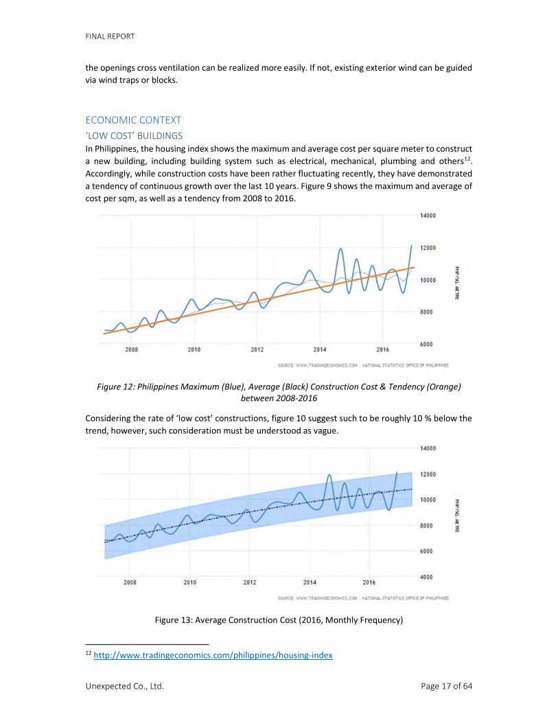
ECONOMIC CONTEXT ‘LOW COST’ BUILDINGS In Philippines, the housing index shows the maximum and average cost per square meter to construct a new building, including building system such as electrical, mechanical, plumbing and others12. Accordingly, while construction costs have been rather fluctuating recently, they have demonstrated a tendency of continuous growth over the last 10 years. Figure 9 shows the maximum and average of cost per sqm, as well as a tendency from 2008 to 2016.
Figure 12: Philippines Maximum (Blue), Average (Black) Construction Cost & Tendency (Orange)
between 2008-2016
Considering the rate of ‘low cost’ constructions, figure 10 suggest such to be roughly 10 % below the trend, however, such consideration must be understood as vague.
Figure 13: Average Construction Cost (2016, Monthly Frequency)
12 http://www.tradingeconomics.com/philippines/housing-index

FINAL REPORT
Unexpected Co., Ltd. Page 18 of 64
In practice, construction costs depend on multiple factors such as the amount of floor area, location, accessibility, regulations and restrictions, topography, building design detailing and specifications, local availability and skillset of labor, material cost, or the source of electricity/water. Because of so many possible individual variances, project related cost calculations require for established building designs and the integration of their local context. Typically, low cost solutions may then be established through comparison of alternative designs and/or specifications.
During design development phases, however, cost predictions and minimizations primarily need for generalization and planning experience. Yet, creating an overview of promising cost efficient design principles may be more useful at such stage. Considering the cost of low to medium rise residential buildings and the current planning stage, low cost for construction can be accomplished by adhering to common design and planning principles such as:
- Simple, orthogonal floor plan layouts that are easy to construct - Use of common building system and technology that allow for significant cost saving - Integration and use of advanced technology of when cost saving is realistic - Minimized ratios of usable space and vertical and horizontal circulation spaces - Sharing and multipurpose usage of public commodity areas - Utilization of common construction techniques that can be realized by low skilled labor - Use of available ordinary finishing’s such as simple ceramic tiles or vinyl floorings, ordinary
paint, etc.13
COMMONLY PRACTICED BUILDING TECHNOLOGY The use of common building technology and construction techniques are another factor to ensure local labor skills are sufficient for proper realization at low cost. Considering low to mid-rise buildings in the Philippines, two types of buildings structures are used; confined masonry or concrete frames with masonry infill. 14
In a confined masonry building, the masonry walls are built using hollow core concrete bricks, before reinforced columns and beams are poured into it. This helps to make a better connection between the walls and the columns making the building more rigid, and thus more earthquake resistant. Confined masonry requires less qualified labor work and is understood as a low-cost construction technique. However, the technique is also prone to improper workmanship and has its limitations when using it for multi-level buildings.
Reinforced concrete frames are typical column beam constructions that overtake the structural load of the building. Consequently, the columns and beams sizes increase, and are erected prior to the wall. This makes for a weaker connection and requires for sufficient number of tie-ins to maintain the bond between wall and structure. 15 The method is more cost intensive and common buildings with multiple stories where the columns and beams must be much larger and stronger.
Most masonry work used in the Philippines is realized with the use of modular buildings bocks, also known as hollow core concrete blocks. In the following figures x and x, data sheets for a modular building block and a pre-fabricated ceiling plates are shown as possible construction elements.
13 http://sibonga.com/philippine_house_pictures.htm 14 Residential Design and Construction Guidelines, www.buildchange.org 15 Handbook on Good Building Design and Construction in the Philippines, GTZ Office Manila / UNDP Regional Centre in Bangkok / The Secretariat of the International Strategy for Disaster Reduction

FINAL REPORT
Unexpected Co., Ltd. Page 19 of 64
MODULAR BLOCK SYSTEM 16
`
Figure 14: Product Data Sheet Modular Block System
16 JackBilt Industries (http://www.jackbilt.com.ph/)

FINAL REPORT
Unexpected Co., Ltd. Page 20 of 64
RIPPED SLAP SYSTEM 17
Figure 15: Product Data Sheet Ripped Slap System
17 JackBilt Industries (http://www.jackbilt.com.ph/)

FINAL REPORT
Unexpected Co., Ltd. Page 21 of 64
ALTERNATIVE SCHEMATIC DESIGNS With the conclusion on possible environmental and economic design measures for design improvement, two schematic designs were developed and presented. The schemes are briefly described and illustrated in the following.
SCHEME A Scheme A is designed to accommodate up to 288 (12x6x4) units sized 33 sqm, and 272 (17x4x4) units sized 24 sqm. For each apartment type, separate buildings have been foreseen. Altogether, six buildings are allocated for the government employees to the North of the property, and the four buildings for the informal dwellers to the South of the property. Between the two building types a green area for multi-purpose use that is accessible from both sides, as well as the service building for the vacuum sewage pumps is allocated.
The buildings are accessible by one main road along the West side of the land, connecting the North and South entrances of the property. Along the road, parking spaces for cars and motor cycles, as well as garbage collection areas are provided.
To optimize the access to the buildings, the design foresees to link two adjacent building units to one main stair case. This way the overall number of stairs can be reduced. All stairs lead from the 1st to the 4th floor level without connecting to the roof of the buildings. Roof access is foreseen separately via openings in the ceilings and the use of mobile ladders whenever necessary. This way misuse of the roof areas as well as cost saving can be achieved. The roof surfaces are constructed as flat concrete slaps to maintain the chosen construction technique on the floor slaps below, as well as protect against extreme weather conditions. A protective coating against coating and solar radiation.
On the roof levels, necessary fresh water tanks are to be installed in specifically foreseen enclosures.
First floor levels of the buildings are raised 1,5 m above the ground floor level to avoid possible flooding through severe weather conditions, improving for better natural ventilation of the first floor level as well as improving the visual quality between the floor level and its surroundings.
In the buildings, the residential units are connected sideways in a linear manner. A corridor is enabling for access with units along both sides. Every two units share one vertical shaft for plumping installations and eventual water meters. Further, the corridors are not entirely enclosed, with openings to the outside whenever possible to support natural ventilation. In case that security becomes an issue, access through larger openings can be prevented using ventilation blocks.
The design of the residential units further foresees the possibility of allowing for natural ventilation. As for the 33 sqm units for city employees, window openings are generally provided along the exterior walls of the East and West facades and to the corridors of the building. This way a natural ventilation through the residential units can be generally realized. In addition, the residential units are designed as pairs leaving a gap between them for corridor access from the main stair and escape stairs and voids for naturally ventilation. When possible, window openings are allocated to these areas as well to further improving ventilation possibilities of the units.
To protect against solar radiation, horizontal shades are allocated above each floor level as a cantilevered extension to the floor slaps above. To further reduce buildings costs and make individual units more attractive, the units are anticipated as semi-finished, allowing occupants to improve their own gradually and according to their individual budgets available. Thus, installation such as suspended ceilings or flooring (except for the wet areas) may not be provided for.

FINAL REPORT
Unexpected Co., Ltd. Page 22 of 64
SITE LAYOUT
Figure 16: Scheme A - Masterplan

FINAL REPORT
Unexpected Co., Ltd. Page 23 of 64
Figure 17: Scheme A – Vizualiation Site View
Type Area [m2] Percentage
Property Size 22147.00
Gross Floor Area (All Floors) 42130.61 100.0%
Floor Area (1st Floor) 6292.60 14.9%
Buildings Government Employees 14876.86 35.3%
Buildings Informal Settlers 10293.53 24.4%
Green + Parking 12015.07 28.5%
Road 4065.15 9.6%
Sewer 880.00 2.1%
Figure 18: Scheme A - Overview Land Use

FINAL REPORT
Unexpected Co., Ltd. Page 24 of 64
BUILDING LAYOUT
Figure 19: Scheme A - Building layout and orientation
Figure 20: Scheme A - Floor Plan Layout for building of Government Employees

FINAL REPORT
Unexpected Co., Ltd. Page 25 of 64
Figure 21: Scheme A - Floor Plan Layout for building of Informal Settlers
UNIT DESIGN
Figure 22: Scheme A - Floor Plan Layout of Apartment for Government Employees [33 sqm]

FINAL REPORT
Unexpected Co., Ltd. Page 26 of 64
Figure 23: Scheme A - Floor Plan Layout of apartments for Informal Settlers [24 sqm]

FINAL REPORT
Unexpected Co., Ltd. Page 27 of 64
SCHEME B Scheme B is designed to accommodate up to 248 ((16x3x4) + (14x4)) units sized 33 sqm, and 216 (16x3x4) units sized 24 sqm. Like Scheme A, for each apartment type, separate buildings have been foreseen with four buildings allocated for the government employees to the North of the property, and three buildings for the informal dwellers to the South of the property. Also, similar, the overall design foresees the arrangement of buildings in East/West orientation and the building access via one main access road, providing parking spaces for cars and motorbikes and combining garbage collection areas of the building units. Between the buildings are green zones with trees to help shading the elongated facades. Further, in-between the two building types is a green area for multi-purpose use that is accessible from both sides. The building for the vacuum sewage pumps is allocated near to the property access to the South.
Different to the earlier scheme is the direction of the road, which is shifting from the West to the East boundary when half way through the property. This modification aims to separates the land into two housing zones, one for city employees and one for the informal dwellers, more distinctively.
As illustrated in the following figures the overall building layout and orientation of scheme B follows the general understanding described in scheme A, where building types with East/West orientation achieve a better protection against exposure of solar radiation. To allow for more privacy between the buildings, green zone with trees are helping to separate and further protection the facade units with the shading. Multipurpose outdoor areas remain in the center, between the two building types, where the access road is shift from the West to the East side.
All buildings remain separate and do not share vertical access points. Both building types include an interior courtyard to improve natural ventilation and natural lighting conditions the apartment units. The courtyards establish a friendlier surrounding within the building units, providing semi outdoor spaces with higher remain quality. As shown in figure x, the building type for the 33 sqm apartment units is organized via two linear arrays in East West orientation. Natural ventilation is encouraged via cross ventilation in North South direction and stack ventilation via the interior courtyard.
The design for the 24 sqm units building type follows the idea of the 33 sqm unit building type.
A maximum lineup of 9 units can be achieved with a total of 18 units per floor, or, considering four levels of the building, altogether 72 units per building type. Like the 33 sqm apartments, the 24 sqm units are designed to provide openings towards their North and South orientations that ensure their cross-ventilation capability. Additionally, the inner courtyard of the units permit for stack ventilation and the removal of hot air within the corridor areas of the building
On a more social level of understanding the inner courtyard can allow for positive interaction among the residents as it is likely to create a friendlier atmosphere when compared to the stringently organized two sided corridors of common building designs. While probably more user friendly, one disadvantage is the higher amount of corridor space, likely leading to slightly higher construction cost.
The design for the individual apartment units vary only slightly to the first scheme.
Here the bathroom of the 33 sqm units move towards the exterior façade, allowing for their improved natural ventilation and the possibility to connect all fresh and waste water piping’s to one vertical installation shaft. A disadvantage in this proposal is likely the reduced flexibility in reorganizing living or sleeping spaces for individual use. Because the 24 sqm unit is already optimized to increase the usable space no further alterative design solution has been made. No alternative design is provided in Scheme B.

FINAL REPORT
Unexpected Co., Ltd. Page 28 of 64
SITE LAYOUT
Figure 24: Scheme B - Masterplan

FINAL REPORT
Unexpected Co., Ltd. Page 29 of 64
Figure 25: Scheme B – Visualisation Site View
Type Area Percentage Property Size 22147.00
Gross Floor Area (All Floors) 40969.32 100.0% Floor Area (1st Floor) 6006.29 14.7%
Buildings Government Employees 14761.93 36.0% Buildings Informal Settlers 9263.21 22.6%
Green + Parking 11500.90 28.1% Road 4563.27 11.1%
Sewer 880.00 2.1% Figure 26: Scheme B - Overview Suggested Land Use
BUILDING LAYOUT
Figure 27: Scheme B - Building layout and orientation

FINAL REPORT
Unexpected Co., Ltd. Page 30 of 64
Figure 28: Scheme B - Floor Plan Layout for building of Government Employees
Figure 29: Scheme B - Floor Plan Layout for building of Informal Settlers

FINAL REPORT
Unexpected Co., Ltd. Page 31 of 64
UNIT DESIGN
Figure 30: Scheme B - Floor Plan Layout of Apartment for Government Employees [33 sqm]
Figure 31: Scheme B - Floor Plan Layout of apartments for Informal Settlers [24 sqm]

FINAL REPORT
Unexpected Co., Ltd. Page 32 of 64
FINALIZATION OF ARCHITECTURAL DESIGN With the feedback on the presented design schemes, a final design was generated based on the selection of the Nexus Planning team. The design was developed and documented. The response to the suggestions are briefly described and the architectural drawings are illustrated in the following.
SUGGESTIONS AND COMMENTS As a response to the presented design schemes the planning authority of the City of Santa Rosa and the local Nexus team suggested choosing ‘Scheme A’, as it offered to be more economical in terms of apartment unit amount and minimized volume of the building units. In addition to the highlighted sustainable and cost-efficient features of the design, several suggestions were made to be incorporated into the design scheme. In the following the suggestions, combined with a comment regarding their design integration are briefly described:
A. It was suggested that the building floors should be increased from 4 to 5-storeys to maximize the land use accommodating more people. While it is generally possible to add more floor levels to the building units to the existing design, there are concerns regarding the cost efficiency of the building construction, as wells as the amount of densification level reached. Typically, increasing the amount of floor levels would raise the question whether elevators needed to be included, which are known to significantly increase construction costs. With international building regulations suggesting elevators for levels above the fourth-floor level for multi-residential buildings. Existing building code requirements may, however, still differ and accept such. The structural integrity of using a confined masonry construction technique may also be compromised when adding floor levels. Such may not only require for already costlier structurally detached column beam construction, but also increased masonry ty-ins considering necessary earthquake precautions. Concerning the overall population density on site, assuming an average 3-person household per unit, the suggested buildings design with four levels would amount to a total of 1,680 residents, and 2,100 residents when considering five floor levels. Considering the earlier mentioned population density of Santa Rosa with 5,033 people per square kilometer (p/sqkm), the calculated population density on site is significantly higher with 75,855 p/sqkm, and 94,821 p/sqkm respectively. With the design proposal being a high-density area already, it is suggested to not further increase the amount of floor levels, but to keep the existing relation of green area and the number of inhabitants to avoid possible social conflicts.
B. The elevation from the ground will be retained, however, the finished grade line to finished floor line of 1m in height based on the proposal will be decreased to 0.50m thru embankment. In the proposed design scheme, the floor level was raised 1.5 m from the surrounding ground level to prevent possible flooding hazards to the apartment units and avert possible break ins into the first-floor levels units. As suggested, a minim height level of 1.0 m above the surrounding ground floor level is realized in the final design. It should be noted that further reducing the height difference further will make the exit of the escape stairs become obsolete. The planned embankment will also need to be lowered in that area to allow exit.
C. A provision for an administrative and homeowners’ association office has been advised.

FINAL REPORT
Unexpected Co., Ltd. Page 33 of 64
In the revised design, an office space is provided for as replacement of one 33 sqm apartment unit. It is shown in the first- floor plan layout of the final design of the building type for government employees.
D. A space for a trench-type detention pond should be implemented into the masterplan design to ensure flooding damages will be minimized and comply with the provisions of the LGU's land developer's guidebook. A detention pond is foreseen behind the multi-purpose areas in the center of the property. Trenches leading to detention pond can also be realized along the property boundary to the East.
E. It is recommended that the buildings and units have no ceilings adopting 'industrial design' wherein the pipes are exposed. The final design does not provide suspended ceilings within the building to ensure cost efficiency. Windows and openings are within sufficient distance to ceilings to allow owners installing suspended ceilings individually if desired.
F. All cables and wires are embedded The suggestion has been noted and agreed to, however, in the current stage drawing documentation stage it may not recognizable. Embedded installation and wiring may also depend on the finally decided construction technique and structural dimensioning of the engineers.
G. 30% of the total area should be devoted as 'open space' per the Philippine guidelines of the Housing and Land Use Regulatory Board In the respect to the current design the total area of open space is calculated as: The following figure shows the overall area distribution on the property:
Type Area Percentage Property Size 22,147.00
Gross Floor Area (All Floors) 22,592.91 100.0% Floor Area (1st Floor) 5,822.82 14.7%
Buildings Government Employees … 36.0% Buildings Informal Settlers … 22.6%
Streetscape 4,830.11 28.1% Landscape 11,494.07 11.1%
Sewer 880.00 2.1% Figure 32: Final Design - Overview Suggested Land Use
H. Separate outdoor multi-purpose areas for the government employees and informal families
should be provided.

FINAL REPORT
Unexpected Co., Ltd. Page 34 of 64
In the final Masterplan, two outdoor multi-purpose areas are allocated in center of the land plot, between the two building areas for government employees and informal settlers. They are visual separated by the access and technical building for the vacuum pumps.
I. Develop 2 or 3 designs which the homeowners can choose from which they can adopt taking into consideration the proposed design and lay-out, i.e., laundry area, storage, bedroom/s. The units will be turned-over as 'bare' and improvements will be an added cost to the buyer.
Design variation for apartments, as suggested, do not exist. The units are still foreseen to be sold as ‘bare’. Yet, to ensure cost efficiency the units have been designed in a way that later changes by homeowners can be realized without interfering existing building installations. Currently, the apartment designs are divided into two zones: a smaller Zone A allocated along the corridors wall and combining entrance area, kitchen, and bathroom areas, and a larger Zone B for living/sleeping purposes. It is foreseen that technical installations such as plumbing remain in close distance to the vertical installation shafts and thus remain within the Zone A. Accordingly, a water and power connection for a laundry machine is foreseen in the pantry area.
Later modifications by home owners can be realized in the Zone B to the extent that the area is subdivided to fit individual needs for separate rooms or storage. In the current design of the 33 sqm apartment, the separating wall between the bedroom and living room is anticipated of not being load bearing, can thus be relocated as a drywall system, or removed according to the owners wishes. Considering the 24 sqm apartment unit, design modifications are generally difficult due to the small size of the unit, but can be realized for the living/sleeping area nonetheless.
J. It is also suggested to add 2 units per level for the first three buildings on the left (City
government employees building), for a total of 30 units, to even out the distribution of area and space. The current building dimensions prevent further building expansion when considering necessary setback from the property lines. Adding more units to the existing building volume would thus compromise the natural ventilation concept for the apartment units. In respect to the comments regarding the already increased population density, the final design does not increase the units amount per level.

FINAL REPORT
Unexpected Co., Ltd. Page 35 of 64
FINAL SCHEME DRAWINGS SITE LAYOUT
Figure 33 Final Design - Masterplan

FINAL REPORT
Unexpected Co., Ltd. Page 36 of 64
BUILDING LAYOUT
Figure 34: Final Design - Building Type A for Government Employees - Floor Plan Layout First Floor

FINAL REPORT
Unexpected Co., Ltd. Page 37 of 64
Figure 35: Final Design - Building Type B for Informal Settler - Floor Plan Layout First Floor

FINAL REPORT
Unexpected Co., Ltd. Page 38 of 64
UNIT DESIGN
Figure 36: Final Design - Building Type A for Government Employees – Apartment Unit - Floor Plan Layout
Figure 37: Final Design - Building Type B for Informal Settler – Apartment Unit - Floor Plan Layout

FINAL REPORT
Unexpected Co., Ltd. Page 39 of 64
SUMMARY AND RECOMMENDATION RESULTS SUMMARY Several improvements regarding environmental and economic considerations have been proposed and included in the design. Considering the analysis existing preliminary design the following measurements were integrated:
ENVIRONMENTAL MEASURES Possible natural cross ventilation integration of building and individual apartment units Improved building orientation Improved flooding protection Improved shading of building envelope via extended horizontal shading slaps per floor level Improved shading of building envelope via plantation alongside the elongated façades Improved daylighting through increased vertical window openings with upper transoms Limitation of number of residents per building for the benefit of social balance Integration of geographical hazard considerations (earthquake, flooding)
ECONOMIC MEASURES Simple design based on conventional construction approach (Confined Masonry) Integration and consolidation of repetitive design elements Optimized ratio of areas for units to corridor infrastructure Design of rectangular rooms and shapes Design with continuous and coherent load distribution Design consideration of using ordinary construction materials Design of apartment units anticipating semi-finished condition
RECOMMENDATION With the presented architectural design concluded, it is recommended to remain with the currently proposed amount of apartment units, as an increase of units may not lead to the anticipated cost reduction. It may also lead to increased population density with negative side effects such as social conflict, misuse, and neglect of property.
In case the Nexus Planning team and the planning team of the City of Santa Rosa wants to pursue the realization of the building design as planned, the current architectural design needs for design verification of compliance with existing building regulation codes, a structural engineering calculation and specifications, as well as MEP planning and specifications before obtaining the building approval from the local building authorities and the construction drawing planning and documentation.
April, 2017
Martin Schoch | Unexpected Co., Ltd.

FINAL REPORT
Unexpected Co., Ltd. Page 40 of 64
APPENDIX
DRAWING DOCUMENTS PRE-DESIGN

FINAL REPORT
Unexpected Co., Ltd. Page 41 of 64

FINAL REPORT
Unexpected Co., Ltd. Page 42 of 64
FINAL DESIGN COMPLETE DRAWING DOCUMENTATION BUILDING TYPE A – HOUSING FOR GOVERNMENT EMPLOYEE

FINAL REPORT
Unexpected Co., Ltd. Page 43 of 64

FINAL REPORT
Unexpected Co., Ltd. Page 44 of 64

FINAL REPORT
Unexpected Co., Ltd. Page 45 of 64

FINAL REPORT
Unexpected Co., Ltd. Page 46 of 64

FINAL REPORT
Unexpected Co., Ltd. Page 47 of 64

FINAL REPORT
Unexpected Co., Ltd. Page 48 of 64

FINAL REPORT
Unexpected Co., Ltd. Page 49 of 64

FINAL REPORT
Unexpected Co., Ltd. Page 50 of 64

FINAL REPORT
Unexpected Co., Ltd. Page 51 of 64

FINAL REPORT
Unexpected Co., Ltd. Page 52 of 64

FINAL REPORT
Unexpected Co., Ltd. Page 53 of 64
BUILDING TYPE B – HOUSING FOR INFORMAL SETTLER

FINAL REPORT
Unexpected Co., Ltd. Page 54 of 64

FINAL REPORT
Unexpected Co., Ltd. Page 55 of 64

FINAL REPORT
Unexpected Co., Ltd. Page 56 of 64

FINAL REPORT
Unexpected Co., Ltd. Page 57 of 64

FINAL REPORT
Unexpected Co., Ltd. Page 58 of 64

FINAL REPORT
Unexpected Co., Ltd. Page 59 of 64

FINAL REPORT
Unexpected Co., Ltd. Page 60 of 64

FINAL REPORT
Unexpected Co., Ltd. Page 61 of 64

FINAL REPORT
Unexpected Co., Ltd. Page 62 of 64

FINAL REPORT
Unexpected Co., Ltd. Page 63 of 64

FINAL REPORT
Unexpected Co., Ltd. Page 64 of 64