174 ieee journal of emerging and selected topics in power …
TRANSCRIPT

174 IEEE JOURNAL OF EMERGING AND SELECTED TOPICS IN POWER ELECTRONICS, VOL. 1, NO. 3, SEPTEMBER 2013
Trends in Wind Turbine Generator SystemsHenk Polinder, Senior Member, IEEE, Jan Abraham Ferreira, Fellow, IEEE, Bogi Bech Jensen, Member, IEEE,
Asger B. Abrahamsen, Kais Atallah, Richard A. McMahon
Abstract— This paper reviews the trends in wind turbinegenerator systems. After discussing some important requirementsand basic relations, it describes the currently used systems: theconstant speed system with squirrel-cage induction generator,and the three variable speed systems with doubly fed inductiongenerator (DFIG), with gearbox and fully rated converter, anddirect drive (DD). Then, possible future generator systems arereviewed. Hydraulic transmissions are significantly lighter thangearboxes and enable continuously variable transmission, buttheir efficiency is lower. A brushless DFIG is a medium speedgenerator without brushes and with improved low-voltage ride-through characteristics compared with the DFIG. Magneticpseudo DDs are smaller and lighter than DD generators, butneed a sufficiently low and stable magnet price to be successful. Inaddition, superconducting generators can be smaller and lighterthan normal DD generators, but both cost and reliability needexperimental demonstration. In power electronics, there is a trendtoward reliable modular multilevel topologies.
Index Terms— Direct-drive generators, doubly fed inductiongenerators (DFIGs), generator systems, permanent magnet (PM)generators, wind energy, wind turbines.
I. INTRODUCTION
THE objective of this paper is to review the trends inwind turbine generator systems and to describe a num-
ber of possible future generator systems. Although there arealso smaller wind turbines, this paper focuses on large windturbines. Fig. 1 shows how the wind turbine size has grownover the past decades [1]. Also the wind turbine market hasgrown significantly over the past decades [1].
This paper starts with discussing some important require-ments and basic relations for wind turbine generator systems.Next, it describes the four most commonly used generatorsystems in wind turbines. Subsequently, it reviews someimportant possible future wind turbine generator systems. Itcloses with concluding remarks.
Manuscript received May 6, 2013; revised July 17, 2013; acceptedAugust 26, 2013. Date of publication September 5, 2013; date of currentversion September 19, 2013. This work was supported in part by the EU FP7Project Innwind.EU under Grant 308974 and in part by the EU FP7 ProjectWindrive under Grant 315485. Recommended for publication by AssociateEditor Don F. D. Tan.
H. Polinder and J. A. Ferreira are with the Electrical Power ProcessingGroup and with DUWind, Delft University of Technology, Delft 2628 CD,The Netherlands (e-mail: [email protected]; [email protected]).
B. B. Jensen is with the Center for Electric Power and Energy, Departmentof Electrical Engineering, Technical University of Denmark, Lyngby 2800,Denmark (e-mail: [email protected]).
A. B. Abrahamsen is with the Department of Wind Energy, TechnicalUniversity of Denmark, Roskilde 4000, Denmark (e-mail: [email protected]).
K. Atallah is with the Department of Electronic & Electrical Engi-neering, University of Sheffield, Sheffield S1 4DT, U.K. (e-mail:[email protected]).
R. A. McMahon is with the Electrical Engineering Department, CambridgeUniversity, Cambridge CB2 1TN, U.K. (e-mail: [email protected]).
Color versions of one or more of the figures in this paper are availableonline at http://ieeexplore.ieee.org.
Digital Object Identifier 10.1109/JESTPE.2013.2280428
Fig. 1. Development of power and size of wind turbines. Source:Bundesverband WindEnergie e.V.
II. REQUIREMENTS AND BASIC RELATIONS
A. Requirements
The key objective of the developments in wind turbines isto minimize the cost of energy delivered to the power system.The contribution of the generator system to this objective isto convert the mechanical input energy from the blades intoelectrical energy, again enabling minimization of the cost ofenergy. This has a number of important implications.
1) Capital expenditures (such as manufacturing, transporta-tion, and installation) are important, but not decisive,because operational expenditures (such as repair andmaintenance) also have to be considered.
2) What is the best generator system varies over timebecause the material cost varies over time, as we haveseen for permanent magnets (PMs). Uncertainty aboutthese price developments influences decisions.
3) What is the best generator system depends on thelocation where the turbine is installed, because the totalenergy produced depends on the wind speed.
4) The efficiency of the system is important, but notdecisive, because a system with a lower efficiency thatdelivers energy at a low cost of energy is better.
Besides fulfilling this key objective, wind turbine generatorsystems have to meet a number of other requirements.
1) Grid Connection: To enable large-scale application ofwind energy without compromising power system stability,power system operators have grid codes to describe therequirements for the quality and the form in which the poweris delivered to the system [2]. Wind turbines are required togrid-fault ride-through [or low-voltage ride-through (LVRT)]capability: they have to stay connected and contribute to thegrid in case of a disturbance such as a voltage dip. On thelong term, wind farms should—similar to conventional powerplants—supply active and reactive power for frequency andvoltage control in the power system.
2168-6777 © 2013 IEEE

POLINDER et al.: TRENDS IN WIND TURBINE GENERATOR SYSTEMS 175
2) Reliability and Availability: Especially offshore, oper-ational expenditures may form a significant part (in theorder of 30%) of the cost of energy. Therefore, requirementsrelated to reliability, availability, and maintainability are get-ting more attention and more research in this field is necessary[3]–[9]. Proper protection against the aggressive humid andsalty offshore environment is extremely important.
3) Variable Speed: To enable an optimal match betweenthe generator system and the aerodynamic of the rotor, thegenerator system is required to have a variable speed. Thepower that can be captured from the wind with a wind turbineis given by [1]
P = 1
2ρairCp(λ, θ)πr2
b v3w (1)
where ρair is the air mass density, vw is the wind speed,rb is the rotor radius (or the blade length), and Cp is thepower coefficient, which depends on the specific design of theblade, the blade pitch angle θ , and the tip speed ratio λ (bladetip speed divided by wind speed). The power coefficient ismaximum for a constant tip speed ratio, and therefore at arotational speed proportional to the wind speed.
B. Generator Scaling
The cost of a generator depends on the size and the materialsused. The size of the generator is in first approximationproportional to the rated torque. The shear stress (the forceper square meter of active air-gap surface area) in electricalmachines is given by [10]–[12]
Fd = 1
2As Bg cos γ (2)
where As and Bg are the amplitudes of the fundamentals ofthe stator current loading and the air-gap flux density, and γis the angle between them.
This shear stress is rather constant over a wide range ofmachine types and power levels, because it is the product ofthe flux density, which is limited because of saturation, andthe current loading, which is limited because of dissipation. Byusing forced liquid cooling, this shear stress can be increased[10], but at the cost of reducing the efficiency.
With this shear stress, a first estimate of the generatordimensions of a radial flux generator can be made. The powerproduced by a radial flux generator is given by [12]
P = ωm T = 2πωmr2s ls Fd = 2ωm Fd Vr (3)
where ωm is the mechanical angular speed, rs is the air-gapradius, ls is the axial stack length, and Vr is the rotor volumeof the generator.
The torque level of the generator system increases morethan proportional to the power level. This is because theblade tip speed must be limited to avoid excessive mechanicalforces, wear, and audible noise. If the rated blade tip speedvtrated is assumed independent of the size of the rotor, thenthe mechanical rotational speed of the rotor ωr is inverselyproportional to radius of the rotor. The rated torque can thenbe written as
Trated = Prated
ωmrated= rb Prated
vtrated∝ r3
b ∝ P3/2rated (4)
Fig. 2. Four commonly used generator systems [18].
where (1) was used in the last two proportionalities.
III. CURRENTLY USED GENERATOR SYSTEMS
The four most commonly used generator systems appliedin wind turbines are shown in Fig. 2 and discussed below[13]–[18]. Table I lists the top 10 wind turbine manufacturersof 2012 [19] with the power levels of their products [20]–[29]and the generator systems they use.
A. Constant Speed Squirrel-Cage Induction Generator
During the last decades of the last century, most wind tur-bine manufacturers mainly built constant speed wind turbineswith power levels increasing to ∼1.5 MW. This constant speedsystem consists of a three-stage gearbox and a squirrel-cageinduction generator directly connected to the utility grid. Thissystem (shown in Fig. 3) is also referred to as the Danishconcept.
Above the rated wind speed, the power is mostly limitedusing the classic stall principle: if the wind speed increasesabove the rated wind speed, the power coefficient reduces, sothat the power produced by the turbine remains approximatelyequal to the rated power. Sometimes active stall is used:negative pitch angles are used to limit the power.
The main strength of this system is that it consists of simpleoff-the-shelf components and that, therefore, it is cheap. Twovariants of this system have been used to overcome some ofits disadvantages.

176 IEEE JOURNAL OF EMERGING AND SELECTED TOPICS IN POWER ELECTRONICS, VOL. 1, NO. 3, SEPTEMBER 2013
TABLE I
TOP 10 WIND TURBINE MANUFACTURERS OF 2012, CURRENTLY USED
GENERATOR CONCEPTS AND POWER RANGES [20]–[29]
1) Pole changing induction generators have two statorwindings with different numbers of pole pairs so that theturbine can operate at two constant speeds to increaseenergy yield and reduce audible noise.
2) The semi-variable speed wind turbine has a woundrotor induction generator with an electronically variablerotor resistance. This enables larger speed variations andreduces mechanical loads and power quality problems.This system is sometimes mentioned as a separate gen-erator system [15].
B. Doubly Fed Induction Generator
After 1996, many wind turbine manufacturers changed to avariable speed system with a doubly fed induction generator(DFIG) for wind turbines with power levels above roughly1.5 MW. This system consists of a multistage gearbox, arelatively low-cost standard DFIG and a partly rated powerelectronic converter feeding the rotor winding. Pitch controllimits the output power to rated power at wind speeds aboverated.
The power rating of the converter is ∼25% of the ratedpower, enabling a speed range from roughly 60% to 110%of the rated speed. This is sufficient for a good energy yieldbecause the tip speed ratio can be kept optimal for a large partof the operating range.
Compared with the constant speed system, this systemenables a more flexible match with requirements consideringaudible noise, mechanical loads, power quality, and energyyield. An important disadvantage of this system appearedwhen the grid codes of the power system operators prescribed
Fig. 3. Sketch of a nacelle with gearbox, in this case of a constant speedNEG micon wind turbine. Source: Bundesverband WindEnergie e.V.
grid-fault ride-through capabilities [2]. This was not possiblewith the standard DFIG system, and therefore a lot of workhas been done to enable grid-fault ride-through [30]–[36]. Thiswork has been so successful that general electric (GE), afterchanging to gear and full converter (GFC) systems around2005, changed back to DFIG in 2012 [14].
C. Brushless Generator With GFC
Since around 2005, several large manufacturers have devel-oped variable speed wind turbines with a gearbox, a brushlessgenerator, and a converter for the full rated power. Pitchcontrol limits the output power to rated power at wind speedsabove rated. This system is mainly used to obtain better grid-fault ride-through characteristics than the DFIG and to avoidthe maintenance and the failures of the brushes of the DFIG.However, a fully rated converter has more losses than a partlyrated converter as in the case of a DFIG.
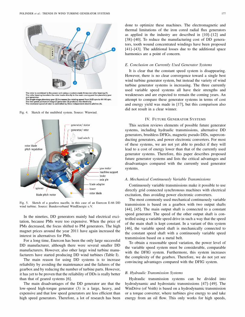
There are quite a number of variants of this system onthe market because different generator types and differentgearboxes are used. Several manufacturers use PM generators,but squirrel-cage induction generators are also used (Table I).The number of gear stages in this system may vary from oneto three. According to (3), a lower number of gear stagesimplies a larger generator, but the resulting system may bemore efficient and more reliable because of the omission ofthe high speed stage of the gearbox [17], [37]. The multibridsystem shown in Fig. 4 has a single stage gearbox and a PMgenerator.
D. Direct-Drive Generator System
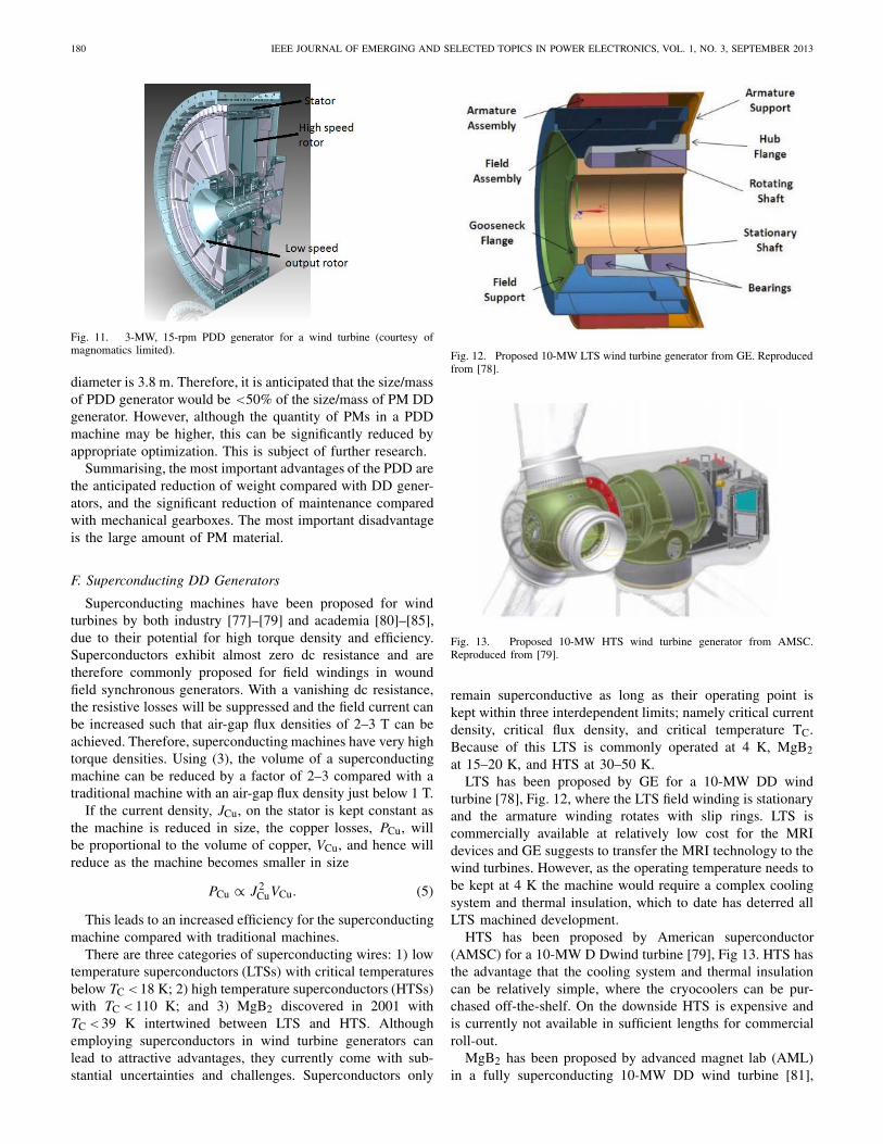
Since 1992, there have also been wind turbine manu-facturers using gearless generator systems with direct-drive(DD) generators as shown in Fig. 5. The generator is asynchronous machine. A fully rated power electronic converteris necessary for the grid connection.
POLINDER et al.: TRENDS IN WIND TURBINE GENERATOR SYSTEMS 177
Fig. 4. Sketch of the multibrid system. Source: Winwind.
Fig. 5. Sketch of a gearless nacelle, in this case of an Enercon E-66 DDwind turbine. Source: Bundesverband WindEnergie e.V.
In the nineties, DD generators mainly had electrical exci-tation, because PMs were too expensive. When the price ofPMs decreased, the focus shifted to PM generators. The highmagnet prices around the year 2011 have again increased theinterest in alternatives for PMs.
For a long time, Enercon has been the only large successfulDD manufacturer, although there were several smaller DDmanufacturers. However, also other large wind turbine manu-facturers have started producing DD wind turbines (Table I).
The main reason for using DD systems is to increasereliability by avoiding the maintenance and the failures of thegearbox and by reducing the number of turbine parts. However,it has yet to be proven that the reliability of DDs is really betterthan that of geared systems [6].
The main disadvantages of the DD generator are that thelow-speed high-torque generator (3) is a large, heavy, andexpensive and that low speed generators are less efficient thanhigh speed generators. Therefore, a lot of research has been
done to optimize these machines. The electromagnetic andthermal limitations of the iron cored radial flux generatorsas applied in the industry are described in [10]–[12] and[38]–[40]. To reduce the manufacturing cost of DD genera-tors, tooth wound concentrated windings have been proposed[41]–[43]. The additional losses due to the additional spaceharmonics are a point of concern.
E. Conclusion on Currently Used Generator Systems
It is clear that the constant speed system is disappearing.However, there is no clear convergence toward a single bestwind turbine generator system, but instead the variety of windturbine generator systems is increasing. The three currentlyused variable speed systems all have their strengths andweaknesses and are expected to remain the coming years. Anattempt to compare these generator systems in terms of costand energy yield was made in [17], but this comparison alsodid not result in a clear winner.
IV. FUTURE GENERATOR SYSTEMS
This section reviews elements of possible future generatorsystems, including hydraulic transmissions, alternative DDgenerators, brushless DFIGs, magnetic pseudo DDs, supercon-ducting generators, and power electronic converters. For mostof these systems, we are not yet able to predict if they willlead to a cost of energy lower than that of the currently usedgenerator systems. Therefore, this paper describes proposedfuture generator systems and lists the critical advantages anddisadvantages compared with the currently used generatorsystems.
A. Mechanical Continuously Variable Transmissions
Continuously variable transmissions make it possible to usedirectly grid connected synchronous machines with electricalexcitation, thus avoiding power electronic converters.
The most commonly used mechanical continuously variabletransmission is based on a gearbox with two output shafts[44], [45]. The main output shaft is connected to a constantspeed generator. The speed of the other output shaft is con-trolled using a variable speed drive in such a way that the speedof the main shaft is kept constant. In a variant of this system[46], the variable speed shaft is mechanically connected tothe constant speed shaft with a continuously variable speedtransmission based on a metal belt.
To obtain a reasonable speed variation, the power level ofthe variable speed system must be considerable, comparablewith the DFIG system. Furthermore, this system increasesthe complexity of the gearbox. Therefore, we do not yet seeconvincing advantages compared with the DFIG system.
B. Hydraulic Transmission Systems
Hydraulic transmission systems can be divided intohydrodynamic and hydrostatic transmissions [47]–[49]. TheWinDrive (of Voith) is based on a hydrodynamic transmissionor a torque converter, where turbines give energy to and takeenergy from an oil flow. This only works for high speeds,

178 IEEE JOURNAL OF EMERGING AND SELECTED TOPICS IN POWER ELECTRONICS, VOL. 1, NO. 3, SEPTEMBER 2013
hence this system is combined with a gearbox. The drive trainsof Wikov, ChapDrive, and Artemis (of Mitsubishi) are basedon hydrostatic transmissions or positive displacement pumps,where cylinders displace pressurized oil. The Wikov systemconsist of a combination of a gearbox and a hydraulic system,while the gearbox is omitted in the systems of ChapDrive andArtemis.
Hydrostatic transmissions have the big advantages that theyare significantly lighter and cheaper than gearboxes [47]. Fur-thermore, hydraulic transmission systems are normally usedas continuously variable transmissions, hence a directly gridconnected synchronous generator can be used, thus avoidingpower electronic converters. However, hydraulic transmissionshave not yet become commercially successful in wind turbines.Reasons are that the efficiency is lower than the efficiency ofa gearbox, and that there is a risk of pollution with oil ifsomething goes wrong. Because these systems have not yetbeen used on a reasonable scale in wind turbines, there is nodata on the reliability of these systems. However, they are usedin many other applications with low speeds and high torques,such as excavators and aeroplanes indicates the reliability canprobably be made acceptable.
C. Alternative DD Generators
Reduction of cost, size, and weight of DD generators forwind turbines is an issue, especially at high power levels,because according to (4) the torque level increases more thanproportional to the power level. Scaling functions illustrate this[50], [51].
To increase the shear stress, the use of transverse flux PMgenerators has been proposed [52]–[57]. However, until nowthe resulting shear stress of the DD generators in this appli-cation has not exceeded that of normal radial flux machinesbecause of the relatively large air gap. Other disadvantages ofthese machines are the low power factor and the complicatedconstruction due to the 3-D flux paths.
If the weight of DD generators is divided into electromag-netically active and structural material, the structural mate-rial is the heaviest part [38], [57]–[65]. Therefore, differentmethods to reduce the amount of structural material have beenproposed.
The idea to use large diameter generators with an aircore to remove the attractive force between stator and rotor[11], [38]–[60] has been adopted by, for example, SwayTurbine [61] (shown in Fig. 6), and Boulder Wind Power [62].Along comparable lines, Goliath [63] uses a large diametergenerator, but this generator seems to have an air-gap windingbetween the stator and rotor iron as described in [64].
Such constructions make it possible to use less electromag-netically active and structural material. However, protection ofthe windings and the magnets against the aggressive environ-ment with humidity and salt is an issue.
In [11], [50], [51], and [65], it is proposed to reducethe distance between the bearings and the location of theelectromagnetic forces using hybrid magnetic bearings or fluidbearings. Again, this enables the use of lighter constructions,but the bearings become more complicated.
Fig. 6. Picture of the large diameter DD generator of Sway Turbine. Source:Sway Turbine.
Fig. 7. Rotor of a brushless DFIG with six nested loops, as used in a machinewith a stator with a four-pole and an eight-pole winding.
D. Brushless DFIG
In [66]–[72], it has been proposed to use the brushlessdoubly fed induction generator (BDFIG), also known as thebrushless doubly fed machine, as a generator for use in windturbines. The BDFIG has two stator windings, one of whichis connected to the grid (the so-called power winding) andthe other (the so-called control winding) is supplied via aconverter, in the same manner as a DFIG. The machine hastwo principal fields, associated with the two stator windings,of different pole numbers which cross couple via the rotor.The rotor has a short-circuited winding consisting of so-callednested loops as shown in Fig. 7. The machine operates in asynchronous mode with a fixed ratio between shaft speed andthe two stator frequencies, again like the DFIG.
The machine was proposed for wind turbine use around1990 by a group at Oregon State University [68] and hasbeen developed since then. The machine is not easy toanalyze despite its simple construction and only recently morestraightforward design procedures have emerged. Followingthe description of relatively small experimental machines [69],several larger machines have recently been built, including a70-kW machine from Brazil [70], a Chinese machine rated at200 kW and what is believed to be the largest machine to datenamely a 250-kW machine built in the UK [67].
These larger machines demonstrate that the BDFIG can bebuilt in larger sizes but a machine with a MW rating remains tobe demonstrated. There are restrictions on the allowable pole

POLINDER et al.: TRENDS IN WIND TURBINE GENERATOR SYSTEMS 179
Fig. 8. Electrical machine accommodated in the bore of high-speed rotor ofmagnetic gear.
numbers of the two principal fields, with the highest availablenatural speed (corresponding to the synchronous speed of aDFIG) with a 2-pole/6-pole combination being 750 rpm on a50-Hz system. Therefore, the BDFIG is seen as a natural partof a medium speed drive with a natural speed in the order of300 rpm. Research is in progress to develop this approach [71].
The BDFIG shares with the DFIG the benefits of low costconstruction in that no PMs materials are used and only a frac-tionally rated converter need be employed. Simultaneously, theabsence of brush-gear obviates one of the main failure modesof the DFIG. Use of the BDFIG therefore gives a low costbut reliable option [66]. The BDFIG also has a significantlyimproved LVRT performance compared with an equivalentDFIG, further reducing system cost and complexity [67].Furthermore, it is a medium speed generator, which increasesthe efficiency and the reliability because the high-speed gearstage of the gearbox is avoided.
Compared with a DFIG of the same speed, a BDFIG has theadvantages that it is brushless and that the LVRT capabilitiesare better and the disadvantage that it probably is slightlylarger because of the additional winding.
E. Magnetic Pseudo DD Generator
A magnetic gear [73], [74] may be combined with anelectrical machine to realise a high torque density magneticallygeared drive in various ways. The simplest and the mostobvious way are to mechanically couple an electrical machineto a magnetic gear as shown in Fig. 8.
Fig. 9, however, shows a pseudo DD (PDD) electricalmachine, where the magnetic gear and the electrical machineare mechanically as well as magnetically integrated [75], [76].The fundamental flux density component of the PMs on thehigh-speed rotor couples with the stator winding to producetorque, while the asynchronous space harmonic resultingfrom the modulation by the ferromagnetic pole pieces ofthe magnetic field of the high-speed rotor PMs couples withthe PMs on stator to transmit torque at fixed gear ratio.When compared with the arrangement shown in Fig. 8, thistopology facilitates access and cooling of the stator windingand simplifies manufacturing significantly, especially for largemachines, since it only has two air gaps.
Fig. 9. PDD with magnetically and mechanically coupled magnetic gear andelectrical machine.
Fig. 10. Air-gap shear stress in PDD and radial field PM machines (electricloading of 1 pu corresponds to the thermal limit of a radial field PM machine).
The electromagnetic torque resulting from the interaction ofthe high speed rotor and the stator windings is similar to thatof a conventional surface mounted PM machine. The magneticgear increases this torque with the gear ratio Gr , which canexceed 10 in a single stage, and hence the torque densitysignificantly increases. Fig. 10 shows a comparison betweenthe typical air-gap shear stress in PDD machines and radialfield PM machines. It can be seen that the torque produced bythe PDD machines is limited by the magnetic gear element,and therefore, the PDD machine would be more suitable forapplications where the peak torque is not significantly higherthan the rated torque, such as wind power generation. It canalso be seen and due the inherently low electric loading, a PDDmachine can operate continuously at its peak torque capability.
Prototypes of magnetic PDD machines have been designedand tested for various applications. A PDD machine witha continuous torque output of 4 kNm has been tested, andprototype with a torque output of ∼20 kNm is currentlygoing through the initial testing phase. However, developmentis in progress to increase torque to magnitudes required forwind turbines. Fig. 11 shows a design of a PDD generatorfor a 3-MW wind turbine, and because of the inherentlylow electric loading, Fig. 11, its rated efficiency is >98%.On the other hand, the total mass of generator, includingthe structural components, is only 35 tons, and the overall
180 IEEE JOURNAL OF EMERGING AND SELECTED TOPICS IN POWER ELECTRONICS, VOL. 1, NO. 3, SEPTEMBER 2013
Fig. 11. 3-MW, 15-rpm PDD generator for a wind turbine (courtesy ofmagnomatics limited).
diameter is 3.8 m. Therefore, it is anticipated that the size/massof PDD generator would be <50% of the size/mass of PM DDgenerator. However, although the quantity of PMs in a PDDmachine may be higher, this can be significantly reduced byappropriate optimization. This is subject of further research.
Summarising, the most important advantages of the PDD arethe anticipated reduction of weight compared with DD gener-ators, and the significant reduction of maintenance comparedwith mechanical gearboxes. The most important disadvantageis the large amount of PM material.
F. Superconducting DD Generators
Superconducting machines have been proposed for windturbines by both industry [77]–[79] and academia [80]–[85],due to their potential for high torque density and efficiency.Superconductors exhibit almost zero dc resistance and aretherefore commonly proposed for field windings in woundfield synchronous generators. With a vanishing dc resistance,the resistive losses will be suppressed and the field current canbe increased such that air-gap flux densities of 2–3 T can beachieved. Therefore, superconducting machines have very hightorque densities. Using (3), the volume of a superconductingmachine can be reduced by a factor of 2–3 compared with atraditional machine with an air-gap flux density just below 1 T.
If the current density, JCu, on the stator is kept constant asthe machine is reduced in size, the copper losses, PCu, willbe proportional to the volume of copper, VCu, and hence willreduce as the machine becomes smaller in size
PCu ∝ J 2CuVCu. (5)
This leads to an increased efficiency for the superconductingmachine compared with traditional machines.
There are three categories of superconducting wires: 1) lowtemperature superconductors (LTSs) with critical temperaturesbelow TC <18 K; 2) high temperature superconductors (HTSs)with TC <110 K; and 3) MgB2 discovered in 2001 withTC <39 K intertwined between LTS and HTS. Althoughemploying superconductors in wind turbine generators canlead to attractive advantages, they currently come with sub-stantial uncertainties and challenges. Superconductors only
Fig. 12. Proposed 10-MW LTS wind turbine generator from GE. Reproducedfrom [78].
Fig. 13. Proposed 10-MW HTS wind turbine generator from AMSC.Reproduced from [79].
remain superconductive as long as their operating point iskept within three interdependent limits; namely critical currentdensity, critical flux density, and critical temperature TC.Because of this LTS is commonly operated at 4 K, MgB2at 15–20 K, and HTS at 30–50 K.
LTS has been proposed by GE for a 10-MW DD windturbine [78], Fig. 12, where the LTS field winding is stationaryand the armature winding rotates with slip rings. LTS iscommercially available at relatively low cost for the MRIdevices and GE suggests to transfer the MRI technology to thewind turbines. However, as the operating temperature needs tobe kept at 4 K the machine would require a complex coolingsystem and thermal insulation, which to date has deterred allLTS machined development.
HTS has been proposed by American superconductor(AMSC) for a 10-MW D Dwind turbine [79], Fig 13. HTS hasthe advantage that the cooling system and thermal insulationcan be relatively simple, where the cryocoolers can be pur-chased off-the-shelf. On the downside HTS is expensive andis currently not available in sufficient lengths for commercialroll-out.
MgB2 has been proposed by advanced magnet lab (AML)in a fully superconducting 10-MW DD wind turbine [81],

POLINDER et al.: TRENDS IN WIND TURBINE GENERATOR SYSTEMS 181
Fig. 14. Proposed 10-MW MgB2 wind turbine generator from AML.Reproduced from [81].
Fig. 14, where both armature and field windings are super-conducting. This implies that the superconductor will carryalternating current, which results in large losses in the super-conductor and consequently large requirements for coolingpower. These losses could be limited by further developmentof MgB2 wires with very small filaments, but currently noMgB2 conductor is ready for alternating current at high fields.MgB2 wire is commercially available at a relatively low priceif the flux density is kept at 1 T. However, if the field isincreased to 3 T the price becomes comparable with HTS atsimilar flux densities and temperatures [81]. MgB2 requires anoperating temperature of 15–20 K and would therefore alsorequire sophisticated cooling systems and thermal insulation.
To summarize, there are three different types of supercon-ductors and all three have been proposed for future 10-MWwind turbines. None of these have been built or demonstratedyet. For other applications, such as ship propulsion, supercon-ducting machines have been built and tested [83]–[85], butthey have not yet become a commercial success. This showsthat the area of superconducting wind turbine generators isvery far from standardization and all paths are still open to beexplored.
G. Power Electronic Converters
In variable speed wind turbine generator systems with partlyor fully rated converter, mostly the standard back-to-backvoltage source inverter is used, both for DFIG systems andfor systems with a full converter [30]–[36], [86]–[88].
This system needs more than one conversion stage to con-vert the frequency and the voltage level making it compatibleto the grid voltage, as is shown in Fig. 15. The growing powerrating is accompanied by the need to increase the voltage onthe dc link between the back-to-back converters. A typicalvalue would be 5 kV for a 3.3.kV primary side grid voltage.To handle these voltages multilevel converters are needed.
The further evolution of wind power systems will be largelydriven by reliability considerations [3]–[9], which implies thatmature multilevel converters such as the three-level neutralpoint clamped topology would be favored. The choice ofsuitable converter topologies and further development ofpower electronic devices and device packages will be largelydriven a better understanding of failure mechanisms and
Fig. 15. Overview of the power conversion components.
Fig. 16. Generator–converter modular multilevel system.
thermal cycling considerations. Especially, the generator sideconverter is badly effected by the temperature cycle behaviorand nonlinear factors of the wind loading such as turbulenceand gusts [89]. In DFIG and superconducting DD systems,the situation is aggravated because power electronic convertershandle ac frequencies that can be in the order of or below 2 Hz,which is comparable with the thermal times constants of thedevice packages.
1) Modular Fault Tolerant Conversion Systems: A highpower converter needs a large number of semiconductordevices and is complicated. This potentially increases the riskof failures. However, if measures can be taken to allow safefailures then the availability of the system operation can beassured. Modular converters are attractive candidates whenfailed units can be bypassed.
In a number of studies, transformerless designs were inves-tigated that are based on the modular multilevel concept forhigh voltage conversion [90]–[92]. The intermediate dc link iseliminated and it is proposed to directly generate an output acor dc voltage in the 10–100-kV range. An attractive feature isthat in offshore wind parks the wind turbines can be connecteddirectly to a MVDC or HVDC collection grid.
In Fig. 16, a schematic of such a modular multilevel systemis shown. The generator is divided into a number of segments,each of which behaves as a three phase or single phase gener-ator on its own. The segments carry the stator windings, whichare electrically isolated from the other winding segments andthe stator core. An active rectifier module converts the ac todc and the units are strung up in series.
Fault tolerance needs to be achieved both in the machinesegment and power electronics module. Electrically a modulecan be bypassed, but it is also necessary to ensure thata winding fault does not cause overheating or creates anundesired breaking torque. The power electronics converterand the machine segment design should incorporate failure

182 IEEE JOURNAL OF EMERGING AND SELECTED TOPICS IN POWER ELECTRONICS, VOL. 1, NO. 3, SEPTEMBER 2013
Fig. 17. Segmented fault tolerant generator–converter system.
Fig. 18. Transformerless modular multilevel converter with dc link [98].
mode, high voltage and thermal engineering solutions usingsome of the principles described in [93] and [94]. The powerconverter and machine segments are physically integrated andthe large reactance of the concentrated stator windings limitsthe current to 1 PU when a short-circuit occurs [94]. Aschematic and a photo of the system are shown in Fig. 17.
2) DC Link Transformerless Generator System: Thegenerator-converter multilevel modular system puts highdemands on the high voltage isolation of the windings of themachine, especially the ground wall isolation. Initial studies,[95], [96] need to be followed up by detailed designs andvalidation on experimental systems. Meeting the isolationrequirements of the large common mode voltage and capac-itive coupling effects due to switching dv/dt’s could be adaunting high voltage engineering challenge. Furthermore, thetorque produced by the generator will be compromised due tothe reduced copper fill factor in the slots due to the volumeof isolation material that needs to be added. The thermalresistance of the windings will also be affected by the isolationmaterial reducing the current density in the conductors. Forthis reason, we prefer solutions that use dc link voltages thatare compatible to existing isolation voltage classes for statorwindings, as used in high power drives [97].
Based on typical voltages used in high power drives, apractical dc link voltage of 1–10 kV should be realisticusing current technology. The voltage is then stepped up toMV/HVDC using a dc step-up converter as shown in thesystem schematic in Fig. 18. It is proposed that the modularmultilevel dc converter concept described in [98] is used sinceit is transformerless and shares the fault tolerance by redundantmodules feature with other modular multilevel converters.
A unique feature of this converter is a secondary power loopthat cycles power between the modules using the principle thatpower at different frequencies are orthogonal to each other.
V. CONCLUSION
There is no convergence toward a single best wind turbinegenerator system, but instead the variety of wind turbine gen-erator systems is increasing. The three currently used variablespeed systems (with gearbox and DFIG, with gearbox andfull converter and DD) are expected to remain for the comingyears. Hydraulic transmissions enable continuously variabletransmission and are significantly lighter than gearboxes, buttheir efficiency is lower. A brushless DFIG is a mediumspeed generator without brushes and with improved LVRTcharacteristics compared with the DFIG. Magnetic PDDs aresmaller and lighter than DD generators, but need a sufficientlylow and stable magnet price to be successful. Also supercon-ducting generators can be smaller and lighter than normal DDgenerators, but both cost and reliability need experimentaldemonstration. In power electronics, there is a trend towardreliable modular multilevel topologies.
REFERENCES
[1] J. F. Manwell, J. G. McGowan, and A. L. Rogers, Wind EnergyExplained: Theory, Design and Application, 2nd ed. Chichester, U.K.:Wiley, 2009.
[2] M. Tsili and S. Papthanassiou, “A review of grid code technicalrequirements for wind farms,” IET Renew. Power Generat., vol. 3, no. 3,pp. 308–332, 2009.
[3] P. Tavner, Offshore Wind Turbines: Reliability, Availability and Mainte-nance, Stevenage, U.K.: IET, 2012.
[4] F. Spinato, “The reliability of wind turbines,” Ph.D. dissertation, SchoolEng., Durham Univ., Durham, England, 2008.
[5] P. J. Tavner, F. Spinato, G. J. W. van Bussel, and E. Koutoulakos,“Reliability of wind turbine subassemblies,” IET Renew. Power Generat.,vol. 3, no. 4, pp. 387–401, Dec. 2009.
[6] H. Arabian-Hoseynabadi, P. J. Tavner, and H. Oraee, “Reliability com-parison of direct-drive and geared drive wind turbine concepts,” WindEnergy, vol. 13, no. 1, pp. 62–73, 2010.
[7] E. Echavarria, B. Hahn, G. J. W. van Bussel, and T. Tomiyama,“Reliability of wind turbine technology through time,” J. Solar EnergyEng., vol. 130, no. 3, pp. 031005-1–031005-8, 2008.
[8] P. J. Tavner, S. Faulstich, B. Hahn, and G. J. W. van Bussel, “Reliabilityand availability of wind turbine electrical and electronic components,”EPE J., vol. 20, no. 4, pp. 1–25, 2011.
[9] H. Polinder, H. Lendenmann, R. Chin, and W. M. Arshad, “Fault tolerantgenerator systems for wind turbines,” in Proc. IEEE IEMDC, May 2009,pp. 675–681.
[10] R. Scott Semken, M. Polikarpova, P. Röyttä, J. Alexandrova,J. Pyrhönen, J. Nerg, A. Mikkola, and J. Backman, “Direct-drivepermanent magnet generators for high power wind turbines: Benefitsand limiting factors,” IET Renew. Power Generat., vol. 6, no. 1,pp. 1–8, Jan. 2012.
[11] M. Mueller and A. Zavvos, “Electrical generators for direct drivesystems: A technology overview,” in Electrical Drives for Direct DriveRenewable Energy Systems, M. Mueller and H. Polinder, Ed. Oxford,U.K.: Woodhead, 2013, pp. 1–29.
[12] H. Polinder, “Principles of electrical design of permanent magnetgenerators for direct drive renewable energy systems,” in ElectricalDrives for Direct Drive Renewable Energy Systems, M. Mueller andH. Polinder, Eds. Oxford, U.K.: Woodhead, 2013, pp. 30–50.
[13] M. Liserre, R. Cárdenas, M. Molinas, and J. Rodríguez, “Overview ofmulti-MW wind turbines and wind parks,” IEEE Trans. Ind. Electron.,vol. 58, no. 4, pp. 1081–1095, Apr. 2011.
[14] E. de Vries, “Wind turbine drive systems: A commercial overview,”in Electrical Drives for Direct Drive Renewable Energy Systems,M. Mueller and H. Polinder, Eds. Oxford, U.K.: Woodhead, 2013,pp. 139–157.

POLINDER et al.: TRENDS IN WIND TURBINE GENERATOR SYSTEMS 183
[15] A. D. Hansen, F. Iov, F. Blaabjerg, and L. H. Hansen, “Review ofcontemporary wind turbine concepts and their market penetration,” WindEng., vol. 28, no. 3, pp. 247–263, 2004.
[16] H. Polinder, S. W. H. de Haan, M. R. Dubois, and J. G. Slootweg,“Basic operation principles and electrical conversion systems of windturbines,” EPE J., vol. 15, no. 4, pp. 43–50, Dec. 2005.
[17] H. Polinder, F. F. A. van der Pijl, G. J. de Vilder, and P. Tavner,“Comparison of direct-drive and geared generator concepts for windturbines,” IEEE Trans. Energy Convers., vol. 21, no. 3, pp. 725–733,Sep. 2006.
[18] H. Polinder, “Overview of and trends in wind turbine generator systems,”in Proc. IEEE Power Eng. Soc. General Meeting, Jul. 2011, pp. 1–8.
[19] International Wind Energy Development—World Market Update 2012,BTM Consult, Copenhagen, Denmark, 2013.
[20] (2013, Sep. 26) [Online]. Available: http://www.ge-energy.com/wind[21] (2013, Apr. 26) [Online]. Available: http://www.vestas.com[22] (2013, Apr. 26) [Online]. Available: http://www.siemens.com/wind[23] (2013, Apr. 26) [Online]. Available: http://www.enercon.de[24] (2013, Apr. 26) [Online]. Available: http://www.suzlon.com[25] (2013, Apr. 26) [Online]. Available: http://www.gamesacorp.com[26] (2013, Apr. 26) [Online]. Available: http://www.goldwindglobal.com[27] (2013, Apr. 26) [Online]. Available: http://www.gdupc.com.cn/[28] (2013, Apr. 26) [Online]. Available: http://www.sinovel.com[29] (2013, Jun. 16) [Online]. Available: http://www.mywind.com.cn/English/
index.aspx[30] Z. Chen, J. M. Guerrero, and F. Blaabjerg, “A review of the state of the
art of power electronics for wind turbines,” IEEE Trans. Power Electron.,vol. 24, no. 8, pp. 1859–1975, Aug. 2009.
[31] R. Cardenas, R. Pena, S. Alepuz, and G. Asher, “Overview of controlsystems for the operation of DFIGs in wind energy applications,” IEEETrans. Ind. Electron., vol. 60, no. 7, pp. 2776–2798, Jul. 2013.
[32] J. Morren and S. W. H. de Haan, “Ridethrough of wind turbineswith doubly-fed induction generator during a voltage dip,” IEEE Trans.Energy Convers., vol. 20, no. 2, pp. 435–441, Jun. 2005.
[33] C. Wessels, F. Gebhart, and R. W. Fuchs, “Fault ride-through of a DFIGwind turbine using a dynamic voltage restorer during symmetrical andasymmetrical grid faults,” IEEE Trans. Power Electron., vol. 26, no. 3,pp. 807–815, Mar. 2011.
[34] A. D. Hansen and G. Michalke, “Fault ride-through capability of DFIGwind turbines,” Renew. Energy, vol. 32, no. 9, pp. 1594–1610, 2007.
[35] G. Pannell, D. J. Atkinson, and B. Zahawi, “Minimum-threshold crowbarfor a fault-ride-through grid-code-compliant DFIG wind turbine,” IEEETrans. Energy Convers., vol. 25, no. 3, pp. 750–759, Sep. 2010.
[36] L. G. Meegahapola, T. Littler, and D. Flynn, “Decoupled-DFIG faultride-through strategy for enhanced stability performance during gridfaults,” IEEE Trans. Sustain. Energy, vol. 1, no. 3, pp. 152–162,Oct. 2010.
[37] H. Li, Z. Chen, and H. Polinder, “Optimization of multibrid permanentmagnet wind generator systems,” IEEE Trans. Energy Convers., vol. 24,no. 1, pp. 82–92, Mar. 2009.
[38] A. McDonald, M. Mueller, and A. Zavvos, “Electrical, thermal and struc-tural generator design and systems integration for direct drive renewableenergy systems,” in Electrical Drives for Direct Drive Renewable EnergySystems, M. Mueller and H. Polinder, Eds. Oxford, U.K.: Woodhead,2013, pp. 51–79.
[39] A. Jassal, K. Versteegh, and H. Polinder, “Case study of the permanentmagnet direct drive generator in the Zephyros wind turbine,” in Elec-trical Drives for Direct Drive Renewable Energy Systems, M. Muellerand H. Polinder, Eds. Oxford, U.K.: Woodhead, 2013, pp. 158–174.
[40] V. Ruuskanen, J. Nerg, M. Niemela, J. Pyrhonen, and H. Polinder,“Effect of radial cooling ducts on the electromagnetic performance ofthe permanent magnet synchronous generators with double radial forcedair cooling for direct-driven wind turbines,” IEEE Trans. Magn., vol. 49,no. 6, pp. 2974–2981, Jun. 2013.
[41] S. Brisset, D. Vizireanu, and P. Brochet, “Design and optimization ofa nine-phase axial-flux PM synchronous generator with concentratedwinding for direct-drive wind turbine,” IEEE Trans. Ind. Appl., vol. 44,no. 3, pp. 707–715, May/Jun. 2008.
[42] H. Polinder, M. J. Hoeijmakers, and M. Scuotto, “Eddy-current losses inthe solid back-iron of PM machines for different concentrated fractionalpitch windings,” in Proc. 3rd IEEE IEMDC, May 2007, pp. 652–657.
[43] A. K. Jassal, H. Polinder, D. Lahaye, and J. A. Ferreira, “Analyticaland FE calculation of eddy-current losses in PM concentrated windingmachines for wind turbines,” in Proc. IEEE IEMDC, Niagara Falls, ON,Canada, May 2011, pp. 727–732.
[44] B.-R. Höhn, “Future transmissions for wind turbines,” Appl. Mech.Mater., vol. 86, pp. 18–25, Oct. 2011.
[45] C. Rossi, P. Corbelli, and G. Grandi, “W-CVT continuously variabletransmission for wind energy conversion system,” in Proc. IEEE Conf.Power Electron. Mach. Wind Appl., Jun. 2009, pp. 1–10.
[46] V. Miltenovic, M. Velimirovic, M. Banic, and A. Miltenovic, “Design ofwind turbines drive train based on CVT,” Balkan J. Mech. Transmiss.,vol. 1 no. 1, pp. 46–56, 2011.
[47] N. Diepeveen, “On fluid power transmission for offshore wind turbines,”Ph.D. dissertation, Dept. Aerosp. Eng., Delft Univ. Technol., Delft, TheNetherlands, 2013.
[48] A. Ragheb and M. Ragheb, “Wind turbine gearbox technologies,”in Proc. 1st INREC, 2010, pp. 1–8.
[49] B. Skaare, B. Hörnsten, and F. G. Nielsen, “Modeling, simulation andcontrol of a wind turbine with a hydraulic transmission system,” WindEnergy, pp. 1–19, 2012, doi: 10.1002/we.1552.
[50] G. Shrestha, H. Polinder, D. Bang, and J. A. Ferreira, “Structuralflexibility: A solution for weight reduction of large direct drive windturbine generators,” IEEE Trans. Energy Convers., vol. 25, no. 3,pp. 732–740, Sep. 2010.
[51] G. Shrestha, “Structural flexibility of large direct drive generatorsfor wind turbines,” Ph.D. dissertation, Electr. Eng. Dept., Delft Univ.Technol., Delft, The Netherlands, 2013.
[52] H. Weh and H. May, “Achievable force densities for permanent magnetmachines in new configurations,” in Proc. Int. Conf. Electr. Mach., 1986,pp. 1107–1111.
[53] J. Hystad, “Transverse flux generators in direct-driven wind energyconverters,” Ph.D. dissertation, Electr. Eng. Dept., Norwegian Univ. Sci.Technol., Trondheim, Norway, 2000.
[54] M. Dubois, “Optimized permanent magnet generator topologies fordirect drive wind turbines,” Electr. Eng. Dept., Delft Univ. Technol.,Delft, The Netherlands, 2004.
[55] D. Bang, “Design of transverse flux permanent magnet machines forlarge direct-drive wind turbines,” Ph.D. dissertation, Electr. Eng. Dept.,Delft Univ. Technol., Delft, The Netherlands, 2010.
[56] D. Svechkarenko, A. Cosic, J. Soulard, and C. Sadarangani, “Trans-verse flux machines for sustainable development—Road transportationand power generation,” in Proc. 7th Int. Conf. PEDS, Nov. 2007,pp. 1108–1114.
[57] A. Zavvos, D. J. Bang, A. Mcdonald, H. Polinder, and M. Mueller,“Structural analysis and optimisation of transverse flux permanent mag-net machines for 5 and 10 MW direct drive wind turbines,” Wind Energy,vol. 15, no. 1, pp. 19–43, Jan. 2012.
[58] J. N. Stander, G. Venter, and M. J. Kamper, “Review of direct driveradial flux wind turbine generator mechanical design,” Wind Energy,vol. 15, no. 3, pp. 459–472, Apr. 2012.
[59] A. S. McDonald, M. A. Mueller, and H. Polinder, “Structural mass indirect-drive permanent magnet electrical generators,” IET Renew. PowerGeneration, vol. 2, no. 1, pp. 3–15, Mar. 2008.
[60] M. J. Kamper, J. H. J. Potgieter, J. A. Stegman, and P. Bouwer,“Comparison of air-cored and iron-cored non-overlap winding radialflux permanent magnet direct drive wind generators,” in Proc. ECCE,Sep. 2011, pp. 1620–1627.
[61] (2013, Apr. 30) [Online]. Available: http://www.swayturbine.com/[62] (2013, Apr. 30) [Online]. Available: http://www.boulderwindpower.com/[63] (2013, Apr. 30) [Online]. Available: http://www.goliath.ee/[64] E. Spooner, P. Gordon, J. R. Bumby, and C. D. French, “Lightweight
ironless-stator PM generators for direct-drive wind turbines,” IEE Proc.Electr. Power Appl., vol. 152, no. 1, pp. 17–26, Jan. 2005.
[65] D. Bang, H. Polinder, J. A. Ferreira, and S.-S. Hong, “Structural massminimization of large direct-drive wind generators using a buoyant rotorstructure,” in Proc. IEEE ECCE, Sep. 2010, pp. 3561–3568.
[66] R. A. McMahon, P. C. Roberts, X. Wang, and P. J. Tavner, “Performanceof BDFM as generator and motor,” IEE Proc. Electr. Power Appl.,vol. 153, no. 2, pp. 289–299, Mar. 2006.
[67] T. Long, S. Shao, E. Abdi, P. Malliband, M. E. Mathekga,R. A. McMahon, and P. J. Tavner, “Symmetrical low voltage ride-through of a 250 kW brushless DFIG,” in Proc. 6th IET Int. Conf.PEMD, Mar. 2012, pp. 1–6.
[68] C. S. Brune, R. Spee, and A. K. Wallace, “Experimental evaluation of avariable speed, doubly-fed wind-power generation system,” IEEE Trans.Ind. Appl., vol. 30, no. 3, pp. 648–655, May/Jun. 1994.
[69] E. Abdi, X. Wang, S. S. Shao, R. McMahon, and P. Tavner, “Perfor-mance characterisation of brushless doubly-fed generator,” in Proc. IEEEIAS Annu. Meeting, Oct. 2008, pp. 1–6.
[70] R. Carlson, H. Voltolini, F. Runcos, P. Kuo-Peng, and N. J. Batistela,“Performance analysis with power factor compensation of a 75 kwbrushless doubly fed induction generator prototype,” in Proc. IEEEIEMDC, May 2007, pp. 1502–1507.

184 IEEE JOURNAL OF EMERGING AND SELECTED TOPICS IN POWER ELECTRONICS, VOL. 1, NO. 3, SEPTEMBER 2013
[71] (2012, Nov. 21). Industrialization of a 3 MW Medium-Speed BrushlessDFIG Drivetrain for Wind Turbine Applications [Online]. Available:http://www.bdfig.com
[72] P. C. Robert, R. A. McMahon, P. J. Tavner, J. M. Maciejowski, andT. J. Flack, “Equivalent circuit for the brushless doubly fed machine(BDFM) including parameter estimation and experimental verifica-tion,” IEE Proc. Electr. Power Appl., vol. 152, no. 4, pp. 933–942,Jul. 2005.
[73] J. Rens, K. Atallah, S. D. Calverley, and D. Howe, “A novel magneticharmonic gear,” IEEE Trans. Ind. Appl., vol. 46, no. 1, pp. 206–212,Jan./Feb. 2010.
[74] P. O. Rasmussen, T. O. Andersen, F. T. Jorgensen, and O. Nielsen,“Development of a high-performance magnetic gear,” IEEE Trans. Ind.Appl., vol. 41, no. 3, pp. 764–770, May/Jun. 2005.
[75] K. Atallah, J. Rens, S. Mezani, and D. Howe, “A novel ‘pseudo’ direct-drive brushless permanent magnet machine,” IEEE Trans. Mag., vol. 44,no. 11, pp. 4349–4352, Nov. 2008.
[76] L. Jian, K. T. Chau, and J. Z. Jiang, “A magnetic-geared outer-rotorpermanent-magnet brushless machine for wind power generation,” IEEETrans. Ind. Appl., vol. 45, no. 3, pp. 954–962, May./Jun. 2009.
[77] C. Lewis and J. Muller, “A direct drive wind turbine HTS generator,”in Proc. IEEE Power Eng. Soc. General Meeting, Jun. 2007, pp. 1–8.
[78] R. Fair, “Superconductivity for large scale wind turbines,” GE GlobalRes., Niskayuna, NY, USA, Tech. Rep. DE-EE0005143, 2012.
[79] G. Snitchler, B. Gamble, C. King, and P. Winn, “10 MW class supercon-ductor wind turbine generators,” IEEE Trans. Appl. Supercond., vol. 21,no. 3, pp. 1089–1092, Jun. 2011.
[80] A. B. Abrahamsen, B. B. Jensen, E. Seiler, N. Mijatovic,V. M. Rodriguez-Zermeno, N. H. Andersen, and J. Østergård, “Fea-sibility study of 5 MW superconducting wind turbine generator,” Phys.C, Supercond., vol. 471, nos. 21–22, pp. 1464–1469, Nov. 2011.
[81] B. B. Jensen, N. Mijatovic, and A. B. Abrahamsen, “Development ofsuperconducting wind turbine generators,” J. Renew. Sustain. Energy,vol. 5, no. 2, pp. 023137-1–023137-12, Apr. 2013.
[82] R. Qu, Y. Liu, and J. Wang, “Review of superconducting generatortopologies for direct-drive wind turbines,” IEEE Trans. Appl. Supercond.,vol. 23, no. 3, Jun. 2013, article nr 5201108.
[83] O. Keysan, “Application of high-temperature superconducting machinesto direct drive renewable energy systems,” in Electrical Drives for DirectDrive Renewable Energy Systems, M. Mueller and H. Polinder, Eds.Oxford, U.K.: Woodhead, 2013, pp. 219–252.
[84] S. S. Kalsi, Applications of High Temperature Superconductors toElectric Power Equipment. Piscataway, NJ, USA: IEEE Press, 2011.
[85] D. Kostopoulos, H. Polinder, and A. van den Brink, “High temperaturesuperconducting generators for direct drive wind turbines: A review,”in Proc. Eur. Wind Energy Assoc. Conf., 2012, pp. 1–10.
[86] F. Blaabjerg, M. Liserre, and K. Ma, “Power electronics convertersfor wind turbine systems,” IEEE Trans. Ind. Appl., vol. 48, no. 2,pp. 708–719, Mar./Apr. 2012.
[87] Z. Chen, “An overview of power electronic converter technology forrenewable energy systems,” in Electrical Drives for Direct Drive Renew-able Energy Systems, M. Mueller and H. Polinder, Eds. Oxford, U.K.:Woodhead, 2013, pp. 80–105.
[88] Z. Chen, “Power electronic converter systems for direct drive renewableenergy applications,” in Electrical Drives for Direct Drive RenewableEnergy Systems, M. Mueller and H. Polinder, Eds. Oxford, U.K.:Woodhead, 2013, pp. 106–138.
[89] A. Isidori, F. M. Rossi, and F. Blaabjerg, “Thermal loading and reliabilityof 10 MW multilevel wind power converter at different wind roughnessclasses,” in Proc. IEEE ECCE, Nov. 2012, pp. 2172–2179.
[90] C. H. Ng, M. A. Parker, L. Ran, P. J. Tavner, J. R. Bumby, andE. Spooner, “A multilevel modular converter for a large, light weightwind turbine generator,” IEEE Trans. Power Electron., vol. 23, no. 3,pp. 1062–1074, May 2008.
[91] F. Deng and Z. Chen, “A new structure based on cascaded multilevelconverter for variable speed wind turbine,” in Proc. 36th Annu. Conf.IEEE IECON, Nov. 2010, pp. 3167–3172.
[92] S. S. Gjerde and T. M. Undeland, “Fault tolerance of a 10 MW, 100 kVtransformerless offshore wind turbine concept with a modular convertersystem,” in Proc. EPE/PEMC, Sep. 2012, pp. LS7c.3-1–LS7c.3-8.
[93] N. R. Brown, T. M. Jahns, and R. D. Lorenz, “Power converter designfor an integrated modular motor drive,” in Proc. IEEE 42nd IEEE IASAnnu. Meeting Conf. Rec., Sep. 2007, pp. 1322–1328.
[94] J. J. Wolmarans, M. B. Gerber, H. Polinder, S. W. H. de Haan,and J. A. Ferreira, “A 50 kW integrated fault tolerant permanentmagnet machine and motor drive,” in Proc. IEEE PESC, Jun. 2008,pp. 345–351.
[95] M. Sztykiel, “Overview of power converter designs feasible for highvoltage transformer-less wind turbine,” in Proc. IEEE ISIE, Jun. 2011,pp. 1420–1425.
[96] P. K. Olsen, S. Gjerde, R. M. Nilssen, J. Hoelto, andS. Hvidsten, “A transformerless generator-converter concept makingfeasible a 100 kV light weight offshore wind turbine: Part I—Thegenerator,” in Proc. IEEE ECCE, Sep. 2012, pp. 247–252.
[97] S. Kouro, J. Rodriguez, B. Wu, S. Bernet, and M. Perez, “Powering thefuture of industry: High-power adjustable speed drive topologies,” IEEEInd. Appl. Mag., vol. 18, no. 4, pp. 26–39, Jul./Aug. 2012.
[98] J. A. Ferreira, “The multilevel modular DC converter,” IEEE Trans.Power Electron., vol. 28, no. 10, pp. 4460–4465, Oct. 2013.
Henk Polinder (M’97–SM’13) received the M.Sc.and Ph.D. degrees from the Delft University ofTechnology, Delft, The Netherlands, in 1992 and1998, respectively.
He has been an Assistant/Associate Professor withthe Electrical Power Processing Group, Delft Uni-versity of Technology, since 1996. He was withLagerwey, Barneveld, The Netherlands, in 1998 and1999, at Philips Applied Technologies, Eindhoven,The Netherlands, in 2002, and at ABB CorporateResearch, Vasteras, The Netherlands, in 2008. He
was a Visiting Professor with the University of Newcastle Upon-Tyne,Newcastle Upon-Tyne, U.K., in 2002, at Laval University, Quebec, QC,Canada, in 2004, and at the University of Edinburgh, Edinburgh, U.K., in2006. He is the author or co-author of over 175 papers. His current researchinterests include design aspects of electrical machines, mainly for renewableenergy applications.
Jan Abraham Ferreira (M’88–SM’01–F’05) wasborn in Pretoria, South Africa. He received theB.Sc.Eng. (cum laude), M.Sc.Eng. (cum laude), andPh.D. degrees in electrical engineering from RandAfrikaans University, Johannesburg, South Africa.
He did research on battery vehicles with theInstitute of Power Electronics and Electric Drives,Technical University of Aachen, Aachen, Germany,in 1981, and as a Systems Engineer with ESD (Pty)Ltd. from 1982 to 1985. From 1986 to 1997, hewas with the Faculty of Engineering, Rand Afrikaans
University, where he held the Carl and Emily Fuchs Chair of power elec-tronics. In 1998, he became a Professor of power electronics and electricalmachines with the Delft University of Technology, Delft, The Netherlands.
Dr. Ferreira was the Chairman of the South African Section of the IEEEfrom 1993 to 1994. He is the Founding Chairman of the IEEE Joint IAS/PELSBenelux Chapter. He served as the Chairman of the IEEE IAS PowerElectronic Devices and Components Committee from 1995 to 1996. He is anAssociate Editor of the IEEE TRANSACTIONS ON POWER ELECTRONICS andserved as a Treasurer and Vice President for meetings of the IEEE PELS. Hewas the Chairman of the CIGRE SC14 National Committee of the Netherlandsfrom 1999 to 2002 and is a member of the Executive Committee of theEuropean Power Electronic Association EPE Society from 1999 to 2003 andfrom 2008 to present.
Bogi Bech Jensen (M’07) received the Ph.D. degreefrom Newcastle University, Newcastle Upon Tyne,U.K. His Ph.D. thesis focused on toroidally woundinduction machines.
He was in the marine sector with roles fromEngineering Cadet to Senior Field Engineer from1994 to 2002. In 2002, he joined academia as aLecturer with the Centre of Maritime Studies andEngineering, Torshavn, Faroe Islands. He moved tothe U.K. in 2004 and became a Research Associatein 2007 and a Lecturer in 2008 with Newcastle
University. He Joined the Technical University of Denmark (DTU), Lyngby,Denmark, as an Associate Professor, in 2009, and is currently the Head ofthe Electric Components Research Group, Center for Electric Power andEnergy, DTU. His current research interests include electrical machine design,analysis, and development.

POLINDER et al.: TRENDS IN WIND TURBINE GENERATOR SYSTEMS 185
Asger B. Abrahamsen received the Ph.D. degreefrom the Technical University of Denmark (DTU),Lyngby, Denmark, in 2003, for the work on smallangle neutron scattering on the flux line lattice in thesuperconductor TmNi2B2C done at Risø NationalLaboratory, Risø, Denmark.
He conducted neutron scattering studies of super-conductors and thermo-electric materials in a post-doctoral position with the DANSCATT Centre from2003 to 2005. He continued with in-situ high energysynchrotron scattering examination of the phase for-
mation of the MgB2 superconductor inside Fe tubes in a post-doctoral positionwith the Materials Research Division, Risø National Laboratory, from 2005to 2006, for sustainable energy at the Technical University of Denmark (RisøDTU). Since 2007, he has been a Senior Scientist with the Materials ResearchDivision, Risø DTU. In 2012, he joined the Wind Energy Department,Technical University of Denmark, with special focus of the application ofadvanced materials such as superconductors and permanent magnets in windturbine generators. His current research interests include the characterizationand applications of superconductors with special focus on superconductingwind turbine generators.
Kais Atallah received the Degree of Ingenieurd’Etat in electrical engineering from Ecole NationalePolytechnique, El Harrach, Algeria, in 1988, andthe Ph.D. degree from the University of Sheffield,Sheffield, U.K., in 1993.
He was a Post-Doctoral Research Associate withthe University of Sheffield from 1993 to 2000. Hethen took up an academic position with the Depart-ment of Electronic and Electrical Engineering, Uni-versity of Sheffield, where he is currently a Professorof electrical engineering. In 2006, he co-founded
Magnomatics Ltd., Sheffield, where he was the Director in 2008. His currentresearch interests include embrace fault-tolerant permanent magnet drivesfor safety-critical applications, magnetic gearing and "pseudo" direct driveelectrical machines, and drive-trains for wind/tidal turbines and electric/hybridvehicles.
Richard A. McMahon received the B.A. degreein electrical sciences and the Ph.D. degree fromCambridge University, Cambridge, U.K., in 1976and 1980, respectively.
He was a University Lecturer of electrical engi-neering with Engineering Department, CambridgeUniversity, in 1989, and became a Senior Lecturer, in2000. His current research interests include electricalmachines and power electronics, particularly forwind and wave power systems.