17a08x1 mx grab-it op inst
TRANSCRIPT

© 2001 Tyco Electronic Product Group PAGE 1 of 32Registered Office: 19-21 Denmark Street, Wokingham, Berks RG40 2QE
EQUIPMENT:
PUBLICATION:
ISSUE No. & DATE:
«¥����¥³¸¾¯¼¸«¾³¹¸«¶¥¶¾®�¥¹·º«¸Ã
MXGRAB-IT17A-08-X1
1 1/01
MXGRAPH CONFIGURATION TOOL
MXGRAB-IT OPERATING INSTRUCTIONS
LIST OF CONTENTS
1) INTRODUCTION 3
2) OVERVIEW 3
3) SYSTEM REQUIREMENTS 3
4) MENU OPTIONS 3
4.1 FILE MENU 3 4.1.1 NEW 3
4.1.2 OPEN 3
4.1.3 CLOSE 4
4.1.4 SAVE 4
4.1.5 SAVE AS 4
4.1.6 SAVE ALL 4
4.1.7 PRINT PREVIEW 4
4.1.8 PRINT 4
4.1.9 PRINT SETUP 4
4.1.10 PREFERENCES 5
4.1.11 EXIT 5
4.2 EDIT MENU 5 4.2.1 UNDO 5
4.2.2 CUT 5
4.2.3 COPY 5
4.2.4 PASTE 5
4.2.5 MODIFY 5
4.2.6 INSERT 6
4.2.7 DELETE 6
4.3 TOOLS MENU 6
4.3.1 UPLOAD MX CONSYS (Panel) 6
4.3.2 CREATE LAYERS (Map) 6
4.3.3 CREATE BLOCKS (Map) 6
4.3.4 CREATE REGIONS (Map) 6
4.3.5 CREATE VIEWS (Map) 6
4.3.6 COMPILE (Project) 6
4.3.7 REPORT (Project) 6
4.3.8 ARCHIVE (Project) 6
4.4 VIEW MENU (All) 6
4.5 WINDOW MENU 6
4.6 HELP MENU 6
5) MXGRAB-IT HIERACHY & ORGANISATION 7 5.1 HIERACHY OF FILES 7
5.2 LOCATION OF FILES 7
5.3 GETTING STARTED 7
5.3.1 CREATING FROM SCRATCH 7
6) FILE STRUCTURE 106.1 GENERAL 10
6.2 PATHS THROUGH MXGRAB-IT FILES 10
6.2.1 INTRODUCTION 10
6.2.2 EVENTS, BEHAVIOUR AND STATUS 10
6.2.3 STYLE OVERRIDES 10
6.2.4 FLOOD FILL COLOURS 10
6.2.5 DANGER STATUS ICONS 10
6.2.6 PROCEDURE PAGES 11
6.3 PROJECT FILES (*.PRJ) 12
6.3.1 PROJECT DETAILS 12
6.4 ACCESS LEVEL FILES (*.LEV) 15
6.5 BEHAVIOUR FILES (*.BHV) 17
6.6 BLOCK FILES (*.BLK) 17
6.7 CATEGORY FILES (*.CAT) 18
6.8 CLASSIFICATION FILES (*.CLS) 19
6.9 CONTROL FILES (*.CTL) 19
6.10 DANGER STATUS FILES (*.DST) 21
6.11 DANGER STATUS ITEM(S) (*.DGR) 21
6.12 DEVICE FILES (*.DEV) 22
6.13 DXF FILES (*.DXF) 22
6.14 EVENT FILES (*.EVT) 22
6.15 EVENT STATUS GROUP (*.ESG) 23
6.16 EVENT STATUS ITEM(S) (*.ESI) 23
6.17 LAYER FILES (*.LYR) 24
6.18 MAP FILES (*.MAP) 24
6.19 PAGE FILES (*.PGE) 26
6.20 PANEL FILES (*.PNL) 26
6.20.1 UPLOAD MX CONSYS 27
6.21 PRINTER CONFIGURATION FILE (*.PRT) 27
6.22 PRIORITY FILES (*.PRI) 28
6.23 PROCEDURE FILES (*.PRC) 29
6.24 POINT FILES (*.PNT) 29
MXGRAB-IT17A-08-X1 1 1/01
PAGE 2 of 32
6.25 SOUND FILES (*.BUZ) 30
6.26 STYLE FILES (*.STY) 30
6.27 TARGET GROUPS (*.GRP) 31
6.28 USER FILES (*.USR) 31
6.29 ZONE FILES (*.ZON) 31
7) MAPS CONFIGURATION 31
7.1 CONFIGURATION OVERVIEW 32
ERROR MESSAGES LIST - APPENDIX A
MXGRAPH EVENT SIMULATOR - APPENDIX B
MAP DETAILS SYNTAX - APPENDIX C

MXGRAB-IT17A-08-X1
1 1/01
© 2001 Tyco Electronic Product Group PAGE 3 of 32Registered Office: 19-21 Denmark Street, Wokingham, Berks RG40 2QE
EQUIPMENT:
PUBLICATION:
ISSUE No. & DATE:
«¥����¥³¸¾¯¼¸«¾³¹¸«¶¥¶¾®�¥¹·º«¸Ã
1. INTRODUCTION The purpose of this document is to provide operatinginstructions for MXGRAB-IT, the configuration tool forMXGraph. MXGRAB-IT enables the user to program acustomised configuration for a particular site.
These Operating Instructions apply to Version 1.0 of theMXGRAB-IT software.
The user should have a good working knowledge of MSWindows and the features provided by MXGraph. The user isexpected to make selections from files/tables.
This publication should be read in conjunction with:
UM33 / 17A-10-U MXGraph USER GUIDE
17A-08-X1 MX CAD OPERATOR GUIDE
2. OVERVIEWMXGRAB-IT is the tool for validating configuration dataand translating it into a form which is compatible withMXGraph. MXGRAB-IT takes advantage of a number offeatures provided by Windows:
• Multiple windows support configuration
• Context sensitive toolbar parameters
• Full scroll bar control, iconisation and resize
MXGRAB-IT is a compiler tool. Throughout this manualdata files will be referred to and used as templates which willeventually be compiled into the final configuration data.Being a compiler tool, MXGRAB-IT benefits from thefollowing features:
• Centralised diagnostic messages
• Cross referencing between different data MX CONSYS sources
• Data verification
3. SYSTEM REQUIREMENTSThe minimum system requirements to run the MXGRAB-ITprogram are:
• A personal computer with MS Windows 95,Windows 98 or Windows NT4
• 16MB RAM for Windows 95 or 24MB forWindows 98 or Windows NT4
Note:
1) The actual amount of RAM and hard disk spacerequired will depend on the number and size ofDXF files included in the project.
2) If MXGRAB-IT is used with screen resolutionsless than SVGA, the views generated mayappear distorted in MXGraph.
• A graphics card capable of supporting SVGA(800 x 600) or better
• 100MB hard disk space
• A 3.5 inch floppy disk drive
• Sound (.WAV) capability
• Windows 95/98 or Windows NT4
• A mouse and standard keyboard
4. MENU OPTIONSThe following menu options are provided depending uponthe currently active window. Some of these options can alsobe accessed by clicking on the Toolbar as shown in Fig. 1overleaf.
The buttons appearing on the Toolbar can change, dependingon the user’s position within MXGRAB-IT.
4.1 FILE MENU
4.1.1 NEW
This command allows the user to create a new file. The useris prompted to select the data type for the file, then an untitleddocument window is opened for the new file. The file is notwritten to disk until the user saves the file.
4.1.2 OPEN
This command allows the user to open an existing file. Thestandard open file dialogue is used to select the required file,offering all the permitted file types. The default file type is‘project files’, being the most common option. A documentwindow is created for the opened file, or an error is reportedif the file cannot be opened.

MXGRAB-IT17A-08-X1 1 1/01
PAGE 4 of 32
Open
Save current file
Save all open
Display
Createdocuments New file
full pagesexisting file
Map
Panel
Style
DevicesCategoriesUser
Priorities
Printer
ClassificationAccess Level
Sounds
ProceduresPage
Event Status Group
Danger StatusControl
HelpConfiguration Target Groups
Fig. 1 Toolbar Icons
Small icons
Large icons Compilation report file
Details of selected window
4.1.3 CLOSE
This command closes the currently active configurationwindow. If the file has been modified, the user is given theoption of saving the file, discarding the changes, orcancelling the close operation. If the file is to be saved thenthe previous file is overwritten, unless it is a new (untitled)document in which case the user is prompted to enter the newfile name and directory.
4.1.4 SAVE
This command saves the file in the active configurationwindow. The file is written back to its existing location ondisk, so the Save command is disabled for new files. (‘SaveAs’ must be used for new files, forcing the user to provide aname and directory for the file). Any error writing to the filewill be reported.
4.1.5 SAVE AS
This command prompts the user to enter a file name anddirectory using the standard ‘Save As’ file dialogue. Thedata is then written to that file (unless the user chooses‘cancel’) and the document window assumes the new filename (shown in the window title bar). Any error writing tothe file will be reported.
4.1.6 SAVE ALL
This command saves all modified, currently open files backto their existing location on disk.
4.1.7 PRINT PREVIEW
This command opens a preview window to show how thecurrently active document window would appear on paper ifprinted. The preview window fills the main MXGRAB-ITwindow, covering all open document windows. Arrowbuttons are provided which allow the user to scan througheach page of the selected document.
4.1.8 PRINT
This command allows the user to print the file in thecurrently active document window. Standard dialogueboxes are used to select the range of pages to be printed or tochange the printer setup. Files are printed in the same formatas they appear in the document window, except that the fileis split onto multiple pages if the file is larger than a page.
4.1.9 PRINT SETUP
This command invokes the standard dialogue box for settingup the printer. It lets the user select which printer to use, thesize of paper, etc.
MXGRAB-IT17A-08-X1
1 1/01
© 2001 Tyco Electronic Product Group PAGE 5 of 32Registered Office: 19-21 Denmark Street, Wokingham, Berks RG40 2QE
EQUIPMENT:
PUBLICATION:
ISSUE No. & DATE:
«¥����¥³¸¾¯¼¸«¾³¹¸«¶¥¶¾®�¥¹·º«¸Ã
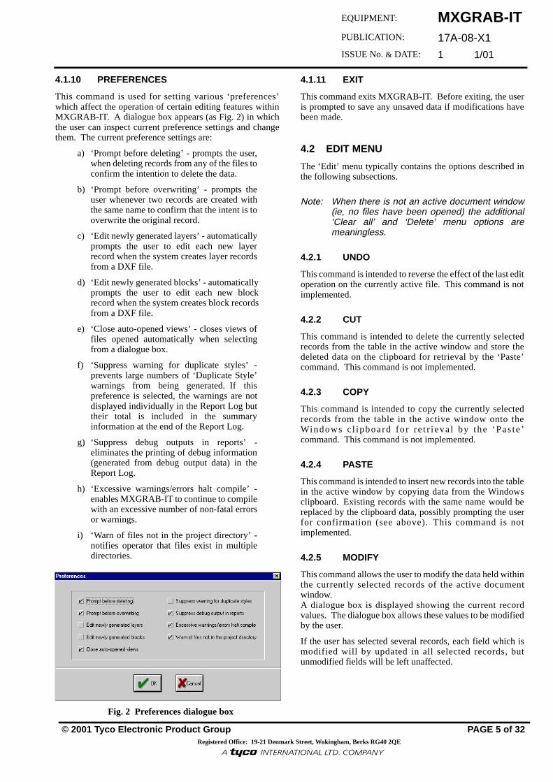
4.1.10 PREFERENCES
This command is used for setting various ‘preferences’which affect the operation of certain editing features withinMXGRAB-IT. A dialogue box appears (as Fig. 2) in whichthe user can inspect current preference settings and changethem. The current preference settings are:
a) ‘Prompt before deleting’ - prompts the user,when deleting records from any of the files toconfirm the intention to delete the data.
b) ‘Prompt before overwriting’ - prompts theuser whenever two records are created withthe same name to confirm that the intent is tooverwrite the original record.
c) ‘Edit newly generated layers’ - automaticallyprompts the user to edit each new layerrecord when the system creates layer recordsfrom a DXF file.
d) ‘Edit newly generated blocks’ - automaticallyprompts the user to edit each new blockrecord when the system creates block recordsfrom a DXF file.
e) ‘Close auto-opened views’ - closes views offiles opened automatically when selectingfrom a dialogue box.
f) ‘Suppress warning for duplicate styles’ -prevents large numbers of ‘Duplicate Style’warnings from being generated. If thispreference is selected, the warnings are notdisplayed individually in the Report Log buttheir total is included in the summaryinformation at the end of the Report Log.
g) ‘Suppress debug outputs in reports’ -eliminates the printing of debug information(generated from debug output data) in theReport Log.
h) ‘Excessive warnings/errors halt compile’ -enables MXGRAB-IT to continue to compilewith an excessive number of non-fatal errorsor warnings.
i) ‘Warn of files not in the project directory’ -notifies operator that files exist in multipledirectories.
Fig. 2 Preferences dialogue box
4.1.11 EXIT
This command exits MXGRAB-IT. Before exiting, the useris prompted to save any unsaved data if modifications havebeen made.
4.2 EDIT MENU
The ‘Edit’ menu typically contains the options described inthe following subsections.
Note: When there is not an active document window(ie, no files have been opened) the additional‘Clear all’ and ‘Delete’ menu options aremeaningless.
4.2.1 UNDO
This command is intended to reverse the effect of the last editoperation on the currently active file. This command is notimplemented.
4.2.2 CUT
This command is intended to delete the currently selectedrecords from the table in the active window and store thedeleted data on the clipboard for retrieval by the ‘Paste’command. This command is not implemented.
4.2.3 COPY
This command is intended to copy the currently selectedrecords from the table in the active window onto theWindows c l ipboard for re t r ieva l by the ‘Paste ’command. This command is not implemented.
4.2.4 PASTE
This command is intended to insert new records into the tablein the active window by copying data from the Windowsclipboard. Existing records with the same name would bereplaced by the clipboard data, possibly prompting the userfor confirmation (see above). This command is notimplemented.
4.2.5 MODIFY
This command allows the user to modify the data held withinthe currently selected records of the active documentwindow.A dialogue box is displayed showing the current recordvalues. The dialogue box allows these values to be modifiedby the user.
If the user has selected several records, each field which ismodified will by updated in all selected records, butunmodified fields will be left unaffected.

MXGRAB-IT17A-08-X1 1 1/01
PAGE 6 of 32
4.2.6 INSERT
This command allows the user to create a new record forinclusion in the currently active document window. Adialogue box is displayed in which the user can enter details/data for the new record.
4.2.7 DELETE
This command deletes the currently selected record(s) of theactive document window. The user is optionally promptedfor confirmation, depending upon the preference settings.
4.3 TOOLS MENU
This menu option is available when certain documentwindows are active and provides specialised facilities forautomatic configuration of various parameters and checkingor compiling the configuration to produce a run-timeconfiguration database for MXGraph.
4.3.1 UPLOAD MX CONSYS (Panel)
This option is available from the Panel file. The commandallows the user to read the data from the MX CONSYSconfiguration file.
4.3.2 CREATE LAYERS (Map)
This option is available from the map file documentwindow. For each se lec ted record , i t reads thecorresponding DXF file and automatically generates anentry in the corresponding layer file for each layer in theDXF file.
If a layer from the DXF file is already present in the layerfile, the existing record is unmodified, otherwise a newrecord is generated. Depending on the preference settings,the user layer editing dialogue box will appear for each suchrecord, allowing the user to fill in the missing layerinformation immediately; otherwise the user must go backand fill in missing information after all records have beencreated.
4.3.3 CREATE BLOCKS (Map)
This option is available from the map file documentwindow. For each se lec ted record , i t reads thecorresponding DXF file and automatically generates anentry in the corresponding block file for each block in theDXF file, in the same way as the ‘Create Layers’ optionabove.
4.3.4 CREATE REGIONS (Map)
This option is available from the map file document, mapediting window. It scans through the DXF file using thelayers selected as region layers and locates all enclosed ornearly enclosed areas. These enclosed areas are built upinto highlight regions and displayed in different colours. Ifsaved, these highlight regions will be written to thecorresponding ‘regions’ DXF file where they can be editedby the user (using AutoCAD or equivalent).
4.3.5 CREATE VIEWS (Map)
This option is available from the map file document, mapediting window. For each selected map and scale itautomatically generates ‘View’ windows in the DXF file fordisplay in MXGraph.
4.3.6 COMPILE (Project)
This option is available from the Project file documentwindow. For each selected record, it reads through allrelated configuration data and builds it into a MXGraph run-time database. A file ‘Report .TXT’ is generated after eachcompilation where diagnostic and error messages are stored.
Note: See Appendix A for a list of error messages.
4.3.7 REPORT (Project)
This option is available when the MXGraph run-time database has been compiled. It allows the ‘Report.TXT’ file tobe viewed and printed.
4.3.8 ARCHIVE (Project)
This option is available from the Project file documentwindow. This command allows the user to archive thecompiled configuration data either to a floppy/disk or to theconfiguration directory, used by MXGraph on the hard driveof the host machine.
4.4 VIEW MENU (All)
This menu is available when certain document windows areactive and provides a quick way to open other files referredto by records within the current document. For each recordwhich is selected, the file it references will be opened anddisplayed. This menu also provides a ‘Large Icons’, ‘SmallIcons’ and ‘Details’ options for all document windows.
4.5 WINDOW MENU
This menu gives ‘Cascade’, ‘Tile’, ‘Arrange Icons’ and‘Close All’ options that are provided by the Windowsenvironment.
4.6 HELP MENU
This menu provides limited help options:
1) CONTENTS - For future use
2) USING HELP - Displays the standard helppages which explain how to use theWindow’s help system.
3) ABOUT - Displays program information,version number and copyright.

MXGRAB-IT17A-08-X1
1 1/01
© 2001 Tyco Electronic Product Group PAGE 7 of 32Registered Office: 19-21 Denmark Street, Wokingham, Berks RG40 2QE
EQUIPMENT:
PUBLICATION:
ISSUE No. & DATE:
«¥����¥³¸¾¯¼¸«¾³¹¸«¶¥¶¾®�¥¹·º«¸Ã
5. MXGRAB-IT HIERACHY AND ORGANISATION
5.1 HIERARCHY OF FILES
An MXGRAB-IT project consists of DXF maps, and data filesthat hold site specific data and customer preferences. Projectswill include all of the types of files in this hierarchy.
In any project, one configuration is produced for eachMXGraph. Even if all the MXGraphs for the project displaythe same information, a different configuration is requiredbecause each MXGraph has a different node address. So theproject file will have a record for each MXGraph at the site.All of these project file records can reference many of thesame sub-files.
The following sections explain the various files that make upan MXGRAB-IT project and the data in them.
5.2 LOCATION OF FILES
All the files for a project are usually kept in one folder.However, MXGRAB-IT allows sub-files of the project file tobe located in different places. This allows files to be sharedbetween projects. The user should be aware that whenworking with projects set up like this, changing a file in oneproject will automatically change the other project.
5.3 GETTING STARTED
5.3.1 CREATING FROM SCRATCH
MXGRAB-IT is provided with a standard library. This is a setof DXF and data files containing default data. It is intended asa starting point from which a project that truly reflects a sitecan be built.
MXGRAB-IT uses a drag-and-drop method to allow a newcopy of an existing project to be created. To do this:
1) Use the menu options File and New to create anew empty project file.
2) Open an existing project. The user is presentedwith a dialogue box similar to the one shownin Fig. 3.
3) Select a record in that project file, drag-and-drop it into the new empty project file.
The user will be prompted for a folder where the new project’sfiles should be. After this, all of the files that make up theexisting project will automatically be copied into the newarea.
These files can now be modified for the new site. The site’sDXF files are set up and referenced from the map file. Thepanels, point, zone and event files are uploaded with datafrom the MX CONSYS configuration. All the other usersettings can be fine-tuned for the needs of the site.
Fig. 4 next page, shows the hierarchy of MXGRAB-IT filesthat make up an MXGRAB-IT project.
Fig. 3 Open dialogue box

MXGRAB-IT17A-08-X1 1 1/01
PAGE 8 of 32
Fig. 4 MXGRAB-IT Hierachy and Organisation
MXGRAB-IT17A-08-X1
1 1/01
© 2001 Tyco Electronic Product Group PAGE 9 of 32Registered Office: 19-21 Denmark Street, Wokingham, Berks RG40 2QE
EQUIPMENT:
PUBLICATION:
ISSUE No. & DATE:
«¥����¥³¸¾¯¼¸«¾³¹¸«¶¥¶¾®�¥¹·º«¸Ã
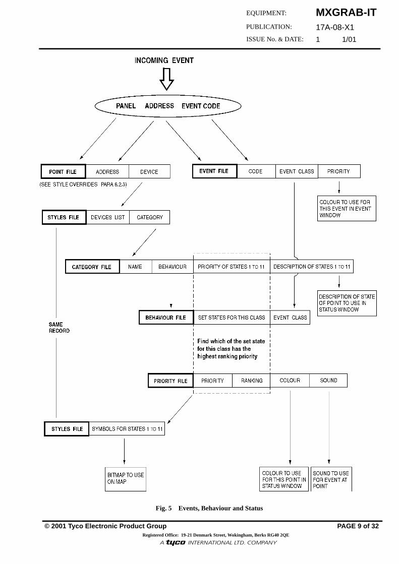
Fig. 5 Events, Behaviour and Status

MXGRAB-IT17A-08-X1 1 1/01
PAGE 10 of 32
6. FILE STRUCTURE
6.1 GENERAL
The data files represented in MXGRAB-IT are presented intabular form. Editing of the data is via the dialogueboxes. The contents of the toolbar and the menu options arecontext sensitive to the focused table. The purpose andlogical structure of each of the files supported byMXGRAB-IT is explained in the following sub-sections.
In addition, MXGRAB-IT uses MX CONSYS .PJD files,bitmap .BMP files and .WAV files.
A document window can be opened to display files intabular form in the following list:
6.2 PATHS THROUGH MXGRAB-IT FILES
6.2.1 INTRODUCTION
There are multiple paths through MXGRAB-IT files.Relationships exist between records in different MXGRAB-IT files. What follows is an explanation of some of theserelationshps and how they determine the behaviour ofMXGraph.
6.2.2 EVENTS, BEHAVIOUR AND STATUS
Fig. 5 shows how MXGRAB-IT files determine:
1) Which bitmap to use on the map for a point in aparticular state.
2) The colour and description to use for a point inthe Status window.
3) The sound to use for an event at a point.
4) The colour to use for the event in the EventWindow and Alert Banner.
Access Levels Maps
Behaviours Pages
Blocks Panels
Categories Points
Classifications Procedures
Controls Projects
Danger status Printers configuration
Danger status items Priorities
Devices Sounds
DXFs Styles
Events Target Groups
Event status groups Users
Event status items Zones
Layers
The following steps detail the order in which Events,Behaviour and Status are decoded:
1) MXGraph gets an Event Code at a point. 2) Goto the Point file and find the Device at
this point. 3) Goto the Styles file and find the Category
that this device is part of. 4) In the Category file, find the Behaviour
file for this category of device. 5) Use the Event Code in the Event file to
find the Event Class of this event. 6) In the Behaviour file, see which states are
set for events of this class. 7) Return to the Category file record that was
found for this category of device. Use the Priority file to see which of thestates that are set, has the highest priority. Use the Description of that state for thepoint in the Status Window.
8) Goto the Styles file and choose the bitmapfor this state with the highest priority.
9) Use the other information in the Priorityfile to decide on the colour for the point inthe status window. The Priority file alsoshows which sound file to use for an eventat a point.
6.2.3 STYLE OVERRIDES
Style is determined by:
1) The Point file style override field is the mostimportant.
2) If this is not set, the Block file style field isused if this point is on a map.
3) If this is not set, the Style file recordscontain a list of devices that have the style.
6.2.4 FLOOD FILL COLOURS
MXGraph maintains a list of the set states of all devices ineach of the device categories in each area. So for all ‘FireDetectors’ category devices in an area, it will remember ifany have the Alarm state set or the Isolate state set, etc.
MXGraph finds the highest priority of any set state on anycategory of device per area. The colour of this priorityidentification is used to fill the area.
6.2.5 DANGER STATUS ICONS
If any point whose category of device is covered in the.DGR file and the state of that point is one of the selectedstates, then the Danger Status bar should include the activeicon from the .DST file.
MXGRAB-IT17A-08-X1
1 1/01
© 2001 Tyco Electronic Product Group PAGE 11 of 32Registered Office: 19-21 Denmark Street, Wokingham, Berks RG40 2QE
EQUIPMENT:
PUBLICATION:
ISSUE No. & DATE:
«¥����¥³¸¾¯¼¸«¾³¹¸«¶¥¶¾®�¥¹·º«¸Ã
If no point whose device is in the range of categories is in anyof these states, then the inactive icon is displayed in theDanger Status bar.
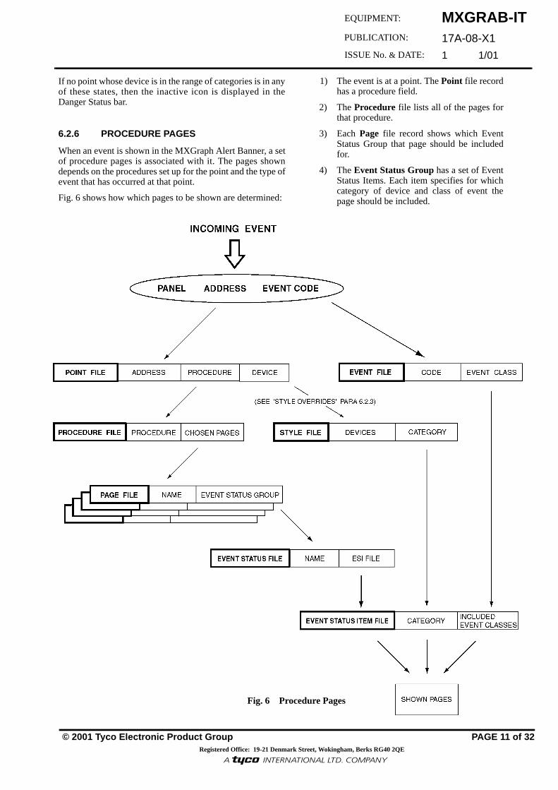
6.2.6 PROCEDURE PAGES
When an event is shown in the MXGraph Alert Banner, a setof procedure pages is associated with it. The pages showndepends on the procedures set up for the point and the type ofevent that has occurred at that point.
Fig. 6 shows how which pages to be shown are determined:
1) The event is at a point. The Point file recordhas a procedure field.
2) The Procedure file lists all of the pages forthat procedure.
3) Each Page file record shows which EventStatus Group that page should be includedfor.
4) The Event Status Group has a set of EventStatus Items. Each item specifies for whichcategory of device and class of event thepage should be included.
Fig. 6 Procedure Pages

MXGRAB-IT17A-08-X1 1 1/01
PAGE 12 of 32
Fig. 7 Project Details dialogue box
FIG. 8SEE
FIG. 9SEE
6.3 PROJECT FILES (*.PRJ)
6.3.1 PROJECT DETAILS
Fig. 7 shows a typical Project Details dialogue box. AProject file is the first level file from which all data relatingto a particular configuration can be reached. Each recordfrom a project file relates to a complete MXGraphconfiguration, meaning a project file will typically containdetails of all configurations for a particular site. The projectfile view provides menu options and toolbar icons to openany of these sub-files shown in Table 1 overleaf. It hastabular fields which specify the filenames of the relevantfiles for the particular configuration.
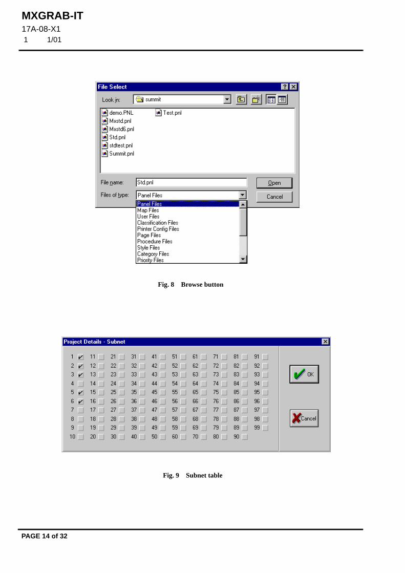
When editing project files, the Project Details dialogue boxhas a Browse button which allows the user to choosefilenames by clicking on them and then clicking the OKbutton. The filename fields can only be set up via theBrowse button.
In general, clicking on any browse button will always bringup a dialogue box similar to the one shown in Fig. 8. TheProject Details dialogue box above provides the followingfields:
Directory Indicates the path where the project files are kept. This fieldis read only.
Name Specifies a name for the configuration. If there is onlyone MXGraph at a site, then this name is usually just thesite name. However, when there is more than oneMXGraph, then the name describes each one. (Name is foruser ID purposes only and is not used by MXGraph).
Overview Logo Specifies the logo bitmap which is displayed whenMXGraph overview button is pressed and by MXGraphscreen saver. Usually a bitmap showing client’s companylogo.
Logo Map Specifies the map which is displayed when MXGraph is inits quiescent state. Typically a map showing the client’scompany logo or a high-level plan of the site.
Default User Specifies the user who will be initially logged-on whenMXGraph first starts up. This user cannot be modifiedwithin MXGraph.
Default Danger Status Specifies the danger status which MXGraph uses forcounting unrestored events. Only points satisfying thespecified danger status will be shown when the userscrolls through points in the banner window. Shoulddefault to ‘Uncleared Points’.

MXGRAB-IT17A-08-X1
1 1/01
© 2001 Tyco Electronic Product Group PAGE 13 of 32Registered Office: 19-21 Denmark Street, Wokingham, Berks RG40 2QE
EQUIPMENT:
PUBLICATION:
ISSUE No. & DATE:
«¥����¥³¸¾¯¼¸«¾³¹¸«¶¥¶¾®�¥¹·º«¸Ã
Default Event Group Specifies the event status group which MXGraph uses forcounting unaccepted events.
Note: This group MUST be set to ‘All Events’ so that allcategories for every event can be seen byMXGraph via the event banner.
Comms Port Specifies the communications port on the MXGraph PC.
Node Address Specifies the node address of the MXGraph within MXNet.
Network Supervisor Specifies whether this MXGraph is to act as networksupervisor.
Time Keeper Specifies whether this MXGraph uses the PC clock to act asnetwork timekeeper.
Non Broadcast Unit If ticked (default setting), MXGraph will accept event logdata from MXNet having MXGraph as the destination.
If NOT ticked, MXGraph will accept event log data fromMXNet having All Panels (Broadcast) as the destination.
Act on Network Events Specifies whether the PC will respond to Day, Night,Silence, Resound, and Reset broadcast from other panels onthe network and MXGraph.
Subnet A list of the node addresses that belong to the MXGraphsubnet configuration. (The project MXGraph node does nothave to be included).
Modify Subnet table 1-99 Fig. 9 displays which node addresses belong to the PC’ssubnet configuration. Add Node Addresses by left-clickingon the boxes. It is not required to check the PC’s ownaddress.
Area Description Area Description by Zone or Sector. This specifies whichformat to use when describing addresses.
Show on Event List Specifies whether an area description should be included inthe details for the Event Window.
Event Logging Log Own Events - this specifies whether local events shouldbe added to the local log.
Node Address 1-5 (Fault Logging) Specifies the node addresses to which MXGraph will sendlogged events for its internally generated faults. A zeroindicates an unused entry. A value of 255 indicates thatinternal events are broadcast to the MXNet.
FIELD DEFAULT
Panels MXSTD.PNL
Maps STD.MAP
Users STD.USR
Classifications MXSTD.CLS
Printers EMPTY.PRT
Pages STD.PGE
Procedures STDPROC.PRC
Styles MXSTD.STY
Categories MXSTD.CAT
Priorities STDPRIO.PRI
Devices MXSTD.DEV
Access Levels MXSTD.LEV
Sounds STD.BUZ
Controls MXSTD.CTL
Danger Status STD.DST
Event Status STD.ESG
Overview Logo LOGO.BMP
Target Groups MXSTD.GRP
Table 1: Configuration details of sub-files
MXGRAB-IT17A-08-X1 1 1/01
PAGE 14 of 32
Fig. 8 Browse button
Fig. 9 Subnet table

MXGRAB-IT17A-08-X1
1 1/01
© 2001 Tyco Electronic Product Group PAGE 15 of 32Registered Office: 19-21 Denmark Street, Wokingham, Berks RG40 2QE
EQUIPMENT:
PUBLICATION:
ISSUE No. & DATE:
«¥����¥³¸¾¯¼¸«¾³¹¸«¶¥¶¾®�¥¹·º«¸Ã
Fig. 10 Access Level Details dialogue box
6.4 ACCESS LEVEL FILES (*.LEV)
Fig. 10 shows a typical Access Level Details dialogue box.An access level file defines all the access levels availablewhen configuring users. Each access level specifies the setof commands which users at that level are allowed to use.
The following fields exist:
Level Gives a name to the access level. This name is used forconfiguring user access levels.
Number Defines the relative ordering of each access level. Levelnumbers must run from 0 to N inclusive, with level 0 beingthe access level invoked when the user selects the ‘Lock’button in MXGraph. The numbers must be consecutive.
Note: The number should be the same as the settingin MXGraph, otherwise confusion over availablecommands will occur.
When a user with access level: >= 5 logs on, MXGraph generates an ‘Engineer log on’ event3 or 4, MXGraph generates a ‘Manager log on’ event < 3, MXGraph generates an ‘Operator log on’ event.
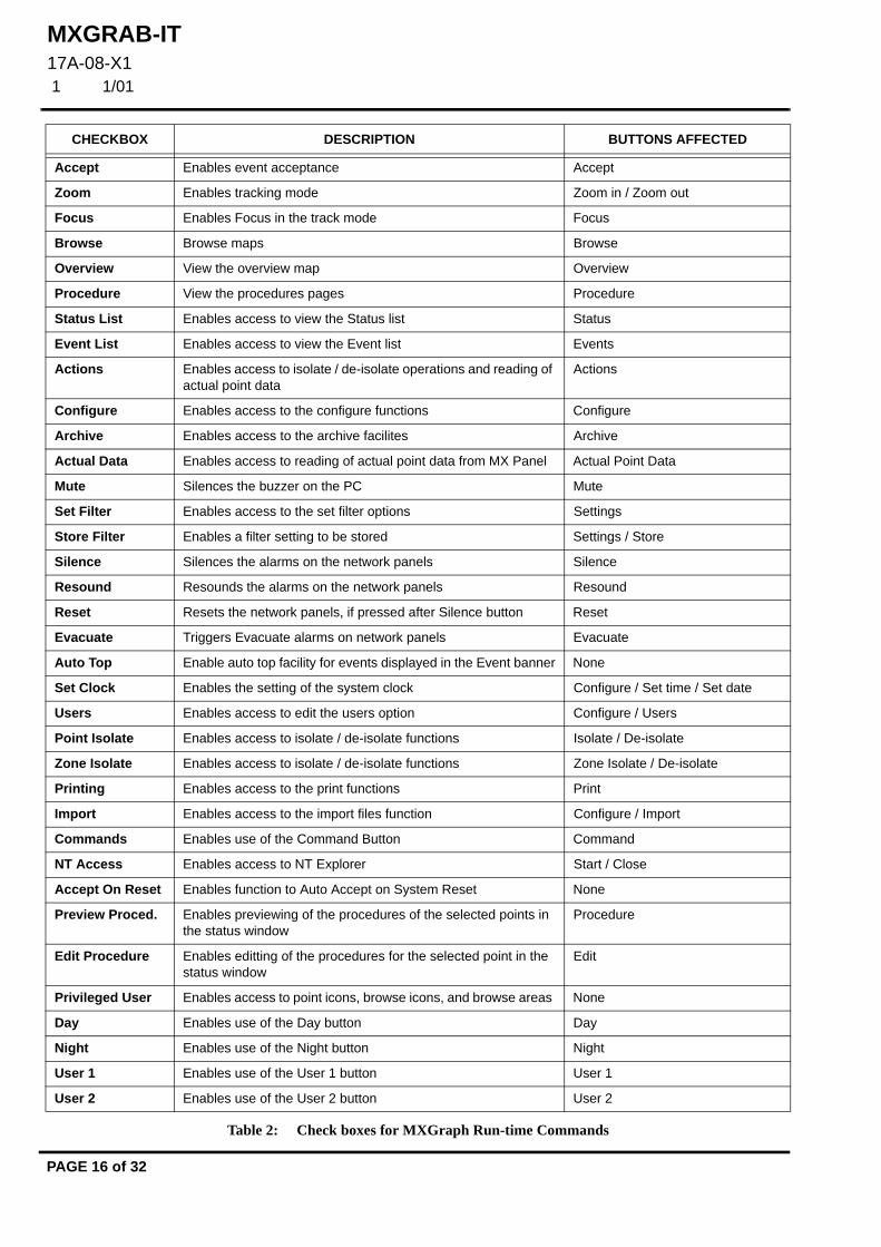
Available Commands This states whether or not each MXGraph feature is availableat the current access level.
For a listing of tick boxes against MXGraph run-timecommands, refer to Table 2 overleaf:
MXGRAB-IT17A-08-X1 1 1/01
PAGE 16 of 32
CHECKBOX DESCRIPTION BUTTONS AFFECTED
Accept Enables event acceptance Accept
Zoom Enables tracking mode Zoom in / Zoom out
Focus Enables Focus in the track mode Focus
Browse Browse maps Browse
Overview View the overview map Overview
Procedure View the procedures pages Procedure
Status List Enables access to view the Status list Status
Event List Enables access to view the Event list Events
Actions Enables access to isolate / de-isolate operations and reading of actual point data
Actions
Configure Enables access to the configure functions Configure
Archive Enables access to the archive facilites Archive
Actual Data Enables access to reading of actual point data from MX Panel Actual Point Data
Mute Silences the buzzer on the PC Mute
Set Filter Enables access to the set filter options Settings
Store Filter Enables a filter setting to be stored Settings / Store
Silence Silences the alarms on the network panels Silence
Resound Resounds the alarms on the network panels Resound
Reset Resets the network panels, if pressed after Silence button Reset
Evacuate Triggers Evacuate alarms on network panels Evacuate
Auto Top Enable auto top facility for events displayed in the Event banner None
Set Clock Enables the setting of the system clock Configure / Set time / Set date
Users Enables access to edit the users option Configure / Users
Point Isolate Enables access to isolate / de-isolate functions Isolate / De-isolate
Zone Isolate Enables access to isolate / de-isolate functions Zone Isolate / De-isolate
Printing Enables access to the print functions Print
Import Enables access to the import files function Configure / Import
Commands Enables use of the Command Button Command
NT Access Enables access to NT Explorer Start / Close
Accept On Reset Enables function to Auto Accept on System Reset None
Preview Proced. Enables previewing of the procedures of the selected points in the status window
Procedure
Edit Procedure Enables editting of the procedures for the selected point in the status window
Edit
Privileged User Enables access to point icons, browse icons, and browse areas None
Day Enables use of the Day button Day
Night Enables use of the Night button Night
User 1 Enables use of the User 1 button User 1
User 2 Enables use of the User 2 button User 2
Table 2: Check boxes for MXGraph Run-time Commands
MXGRAB-IT17A-08-X1
1 1/01
© 2001 Tyco Electronic Product Group PAGE 17 of 32Registered Office: 19-21 Denmark Street, Wokingham, Berks RG40 2QE
EQUIPMENT:
PUBLICATION:
ISSUE No. & DATE:
«¥����¥³¸¾¯¼¸«¾³¹¸«¶¥¶¾®�¥¹·º«¸Ã
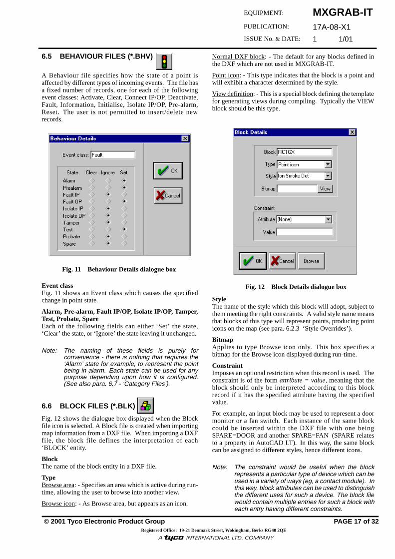
6.5 BEHAVIOUR FILES (*.BHV)
A Behaviour file specifies how the state of a point isaffected by different types of incoming events. The file hasa fixed number of records, one for each of the followingevent classes: Activate, Clear, Connect IP/OP, Deactivate,Fault, Information, Initialise, Isolate IP/OP, Pre-alarm,Reset. The user is not permitted to insert/delete newrecords.
Event class Fig. 11 shows an Event class which causes the specifiedchange in point state.
Alarm, Pre-alarm, Fault IP/OP, Isolate IP/OP, Tamper,Test, Probate, Spare Each of the following fields can either ‘Set’ the state,‘Clear’ the state, or ‘Ignore’ the state leaving it unchanged.
Note: The naming of these fields is purely forconvenience - there is nothing that requires the‘Alarm’ state for example, to represent the pointbeing in alarm. Each state can be used for anypurpose depending upon how it is configured.(See also para. 6.7 - ‘Category Files’).
6.6 BLOCK FILES (*.BLK)
Fig. 12 shows the dialogue box displayed when the Blockfile icon is selected. A Block file is created when importingmap information from a DXF file. When importing a DXFfile, the block file defines the interpretation of each‘BLOCK’ entity.
Block The name of the block entity in a DXF file.
Type Browse area: - Specifies an area which is active during run-time, allowing the user to browse into another view.
Browse icon: - As Browse area, but appears as an icon.
Fig. 11 Behaviour Details dialogue box
Normal DXF block: - The default for any blocks defined inthe DXF which are not used in MXGRAB-IT.
Point icon: - This type indicates that the block is a point andwill exhibit a character determined by the style.
View definition: - This is a special block defining the templatefor generating views during compiling. Typically the VIEWblock should be this type.
Style The name of the style which this block will adopt, subject tothem meeting the right constraints. A valid style name meansthat blocks of this type will represent points, producing pointicons on the map (see para. 6.2.3 ‘Style Overrides’).
Bitmap Applies to type Browse icon only. This box specifies abitmap for the Browse icon displayed during run-time.
Constraint Imposes an optional restriction when this record is used. Theconstraint is of the form attribute = value, meaning that theblock should only be interpreted according to this blockrecord if it has the specified attribute having the specifiedvalue.
For example, an input block may be used to represent a doormonitor or a fan switch. Each instance of the same blockcould be inserted within the DXF file with one beingSPARE=DOOR and another SPARE=FAN (SPARE relatesto a property in AutoCAD LT). In this way, the same blockcan be assigned to different styles, hence different icons.
Note: The constraint would be useful when the blockrepresents a particular type of device which can beused in a variety of ways (eg, a contact module). Inthis way, block attributes can be used to distinguishthe different uses for such a device. The block filewould contain multiple entries for such a block witheach entry having different constraints.
Fig. 12 Block Details dialogue box
MXGRAB-IT17A-08-X1 1 1/01
PAGE 18 of 32
.
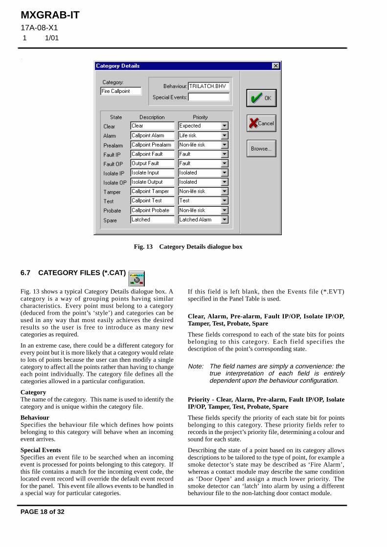
Fig. 13 Category Details dialogue box
6.7 CATEGORY FILES (*.CAT)
Fig. 13 shows a typical Category Details dialogue box. Acategory is a way of grouping points having similarcharacteristics. Every point must belong to a category(deduced from the point’s ‘style’) and categories can beused in any way that most easily achieves the desiredresults so the user is free to introduce as many newcategories as required.
In an extreme case, there could be a different category forevery point but it is more likely that a category would relateto lots of points because the user can then modify a singlecategory to affect all the points rather than having to changeeach point individually. The category file defines all thecategories allowed in a particular configuration.
Category The name of the category. This name is used to identify thecategory and is unique within the category file.
Behaviour Specifies the behaviour file which defines how pointsbelonging to this category will behave when an incomingevent arrives.
Special Events Specifies an event file to be searched when an incomingevent is processed for points belonging to this category. Ifthis file contains a match for the incoming event code, thelocated event record will override the default event recordfor the panel. This event file allows events to be handled ina special way for particular categories.
If this field is left blank, then the Events file (*.EVT)specified in the Panel Table is used.
Clear, Alarm, Pre-alarm, Fault IP/OP, Isolate IP/OP,Tamper, Test, Probate, Spare
These fields correspond to each of the state bits for pointsbelonging to this category. Each field specifies thedescription of the point’s corresponding state.
Note: The field names are simply a convenience: thetrue interpretation of each field is entirelydependent upon the behaviour configuration.
Priority - Clear, Alarm, Pre-alarm, Fault IP/OP, IsolateIP/OP, Tamper, Test, Probate, Spare
These fields specify the priority of each state bit for pointsbelonging to this category. These priority fields refer torecords in the project’s priority file, determining a colour andsound for each state.
Describing the state of a point based on its category allowsdescriptions to be tailored to the type of point, for example asmoke detector’s state may be described as ‘Fire Alarm’,whereas a contact module may describe the same conditionas ‘Door Open’ and assign a much lower priority. Thesmoke detector can ‘latch’ into alarm by using a differentbehaviour file to the non-latching door contact module.

MXGRAB-IT17A-08-X1
1 1/01
© 2001 Tyco Electronic Product Group PAGE 19 of 32Registered Office: 19-21 Denmark Street, Wokingham, Berks RG40 2QE
EQUIPMENT:
PUBLICATION:
ISSUE No. & DATE:
«¥����¥³¸¾¯¼¸«¾³¹¸«¶¥¶¾®�¥¹·º«¸Ã
6.8 CLASSIFICATION FILES (*.CLS)
A classification file defines the set of acceptanceclassifications available when the user accepts an event inMXGraph. The file contains a fixed number of recordsnumbered 0 to 12: the user must not insert/delete newrecords. Each of the existing records may be edited as shownin Fig. 14:
Classification number Identifies the position at which the classification appears int h e l i s t o f c h o i c e s w h en t h e u s e r a cc e p t s a nevent. Classification number 0 is special: events with this astheir default classification are automatically accepted, soclassification number 0 does not appear in the user’s list ofchoices at MXGraph run-time.
Description The text description of this acceptance classification.
6.9 CONTROL FILES (*.CTL)
The Control File gives details of the actions performed whenthe user clicks on certain ‘control points’ in MXGraph.‘Control points’ are Command Buttons on the MXGraphCommand dialogue box and buttons in the Map Window.
For each style of ‘control points’ the Control File identifies:
• The MX Group and target area to use for the rawevent that is broadcast to the panels
• The event code to be added to the logs
The records for Command Buttons are fixed. They cannot bedeleted and some of their fields cannot be changed. Withinthe Control File, the records for Map buttons can be deletedand all of their records can be changed - these are user added.
MXGRAB-IT allows a selection of target areas to beconfigured for control (All Sectors, All Zones, All Areas,Network Zone, Sector) as shown in Fig. 16.
The following descriptions are features of the dialogue boxesdisplayed in Figs. 15 and 16, overleaf:
Fig. 14 Classification Details dialogue box
Style Identifies the style of ‘control point’ which invokes thesecontrol actions.
Button behaviour
Single action on button press The same action is performed each time the button ispressed.
Alternate action on each button press The button toggles between two different actions.
Alternate action on button press/release Two sets of actions are performed each time the button ispressed and released.
Details of Group Control Event Details of the raw event generated by the button action
Active group/Inactive Group A selection of groups.
Target Area Target area for the raw event.
Details of Locally Logged Events Details of the event added to the logs by the button action
Log an Event Whether the event is to be added to the logs.
Event Code Event code to add to the logs.

MXGRAB-IT17A-08-X1 1 1/01
PAGE 20 of 32
CONTROL FILE ALLOWSCONFIGURATION OF THE ACTIONS GENERATED WHEN COMMANDCONTROL BUTTONS AND MAP CONTROL BUTTONS ARE PRESSED.
Fig. 15 Control file table
Fig. 16 Control Details dialogue box
OPTIONS FOR BUTTON BEHAVIOURON MXGRAPH
THESE FIELDS ONLY APPEAR WHEN EITHER OF THE ‘ALTERNATE ACTION’ OPTIONSARE SELECTED.
SELECT FROM THE STYLE LIST
HEADINGS CHANGE ACCORDING TO BUTTONBEHAVIOUR SELECTION
{{ADD/
DELETEBY USER
FIXED,ALWAYSAPPEARS ONMXGRAB-ITFILE
COMMANDCONTROL
MAPCONTROL

MXGRAB-IT17A-08-X1
1 1/01
© 2001 Tyco Electronic Product Group PAGE 21 of 32Registered Office: 19-21 Denmark Street, Wokingham, Berks RG40 2QE
EQUIPMENT:
PUBLICATION:
ISSUE No. & DATE:
«¥����¥³¸¾¯¼¸«¾³¹¸«¶¥¶¾®�¥¹·º«¸Ã
6.10 DANGER STATUS FILES (*.DST)
The Danger Status file defines all the danger status groupscontained within a particular MXGraph configuration. Thedanger status groups are used for filtering particular pointsdepending upon their category and state. The file enables theuser to visually indicate the Danger Status in the EventBanner by associating an active and inactive icon to thedanger status.
Each Danger Status defined in the table could be used as afilter during MXGraph run-time. For example, if it isrequired to place a filter on MXGraph on all alarms status,then it is possible to create a Danger Status labelled ‘AllAlarms’, and assign to it an Alarm .DGR file which containsall the relevant categories with the alarm state checked.
The Danger Status Preview bar below in Fig. 17 displaysactive or inactive icons as they would appear or theMXGraph Danger Status Bar. Left-click on the display totoggle between active and inactive icons.
Danger Status The name of the danger status group. This is the name theuser sees when selecting a particular danger status group, ie,when choosing filter settings in MXGraph’s point statuswindow.
Danger Items The filename of the danger item file which defines theparticular category/point state combinations included withinthis danger status group.
Active Icon The icon to use when ANY of the points included in thisDanger Status are in one of the required states.
Inactive Icon The icon to use when NONE of the points included in thisDanger Status are in one of the required states.
Fig. 17 Danger Status Preview bar with dialogue
Icon position
The position of the bitmap in the Danger Status Bar. Thenumber represents the distance from the left-hand side of thebar.
6.11 DANGER STATUS ITEM(S) (*.DGR)
A Danger Status Item file defines the set of category/statecombinations which are included in a danger statusgroup. The file contains one record per category, althoughcategories which are not included in the danger status groupmay be omitted. A typical example of this dialogue box isshown in Fig. 18 showing no omissions.
Category The name of the category to be included within the dangerstatus group.
Clear, Alarm, Pre-alarm, Fault IP/OP, Isolate IP/OP,Tamper, Test, Probate, Spare The fields corresponding to each of the states of a pointwithin the selected category. A point is included within thedanger status group only i f the state f ield for thecorresponding category is selected.
Fig. 18 Danger Item Details dialogue box

MXGRAB-IT17A-08-X1 1 1/01
PAGE 22 of 32
6.12 DEVICE FILES (*.DEV)
The Device file identifies the different types of devicewhich the system will recognise. Device types are usedfor cross-checking the styles derived from blocks in a.DXF file when importing point information. Each stylecan be restricted to particular types of device. The DeviceDetails dialogue box is shown in Fig. 19:
Device code The numeric value used by MX to identify a particulardevice type. ‘Device code’ is sub-divided into four sub-sections, allowing the user to specify device parameters.
Class The pull-down menu provides a choice of settings:
‘Digital, MX Digital, Pseudo’ are used at panel points ‘Special’ is used at MXGraph points ‘Thorn’ is selected for older Thorn Security devices.
Code, Mode, Sensitivity For devices used at panel points, these settings mustcorrespond to the setting used in the MX Panelenvironment.
6.13 DXF FILES (*.DXF)
DXF files contain CAD drawings compatible withAutoCAD and other packages but drawn in such a waythat the normal CAD data can be supplemented withMXGraph specific configuration information. A CADfile primarily comprises structured ‘entities’ which makeup the CAD drawing, with each entity being described byvarious tags which define its position, size, shape, layer,colour, etc. The division of a CAD drawing into separatelayers provides useful information to MXGRAB-IT whenit is deciding how each entity should be interpreted.
Fig. 19 Device Details dialogue box
A particularly important type of entity is the ‘BLOCK’. Ablock is a grouping of other entities which can then bereferred to by name and used many times in differentlocations within the CAD drawing.
Blocks can also be supplemented by ‘attributes’ whichattach to each instance of the block and associate userspecified text with them.
MXGRAB-IT does not fully recognise every tag of everyentity. Currently some of the features not supported include:
• Z-coordinates in 3D drawings are ignored
• Line types and Line widths are ignored.Hatching is not recognized
• System variables are ignored.
Use of these features does not cause any adverse side effects,but these features will not be correctly interpreted and maynot be preserved when MXGRAB-IT saves the file.
6.14 EVENT FILES (*.EVT)
An Event file defines the configuration of MX event codeswhen handling incoming events. The dialogue box is shownin Fig. 20:
Event code The raw event code contained within the incoming event.This is used to identify the correct record within the file.
Description A textual description of the event code. The descriptionwould typically be the same as the event description used byMX when displaying events on its Front Panel, but it ispossible to define special interpretations for events (eg,using a special event file in the category table for a particularcategory of point to override selected events from the panel’s
Fig. 20 Event Details dialogue box

MXGRAB-IT17A-08-X1
1 1/01
© 2001 Tyco Electronic Product Group PAGE 23 of 32Registered Office: 19-21 Denmark Street, Wokingham, Berks RG40 2QE
EQUIPMENT:
PUBLICATION:
ISSUE No. & DATE:
«¥����¥³¸¾¯¼¸«¾³¹¸«¶¥¶¾®�¥¹·º«¸Ã
default event table, the event ‘INPUT ACTIVE’ could betranslated into a more meaningful message such as ‘DOOROPEN’).
Priority Defines the priority of the event code. This priority refersto a name in the priority file, defining the relative orderingof event codes, and a colour to use when displaying theevent.
Event Class The class of the event, used when interpreting behaviourrecords to update the state of a point.
Classification The (optional) default acceptance classification for thisevent code. This classification is pre-selected when theuser accepts the event but can be overridden before the userconfirms the acceptance. The special classification ‘Autoaccept’ means that this event code will be automaticallyaccepted by MXGraph and will not appear in the eventbanner for acceptance by the user.
6.15 EVENT STATUS GROUP (*.ESG)
This is similiar to the Danger Status Group file but appliesto events. The dialogue box is shown below in Fig. 21. TheEvent Status Group file defines all the event status groupscontained within a particular MXGraph configuration. TheEvent Status Groups are used for filtering particular eventsdepending upon their category and event class.
Name The name of the event status group. This is the name theuser sees when selecting a particular event status group, eg,when choosing filter settings in the MXGraph’s eventlisting window.
Event Status Items The filename of the event status item file which defines theparticular category/event class combinations includedwithin this event status group.
The event status groups could be used as filters duringMXGraph run-time, for example, all points, alarms only,isolates only etc.
Fig. 21 Event Status Details dialogue box
6.16 EVENT STATUS ITEM(S) (*.ESI)
An Event Status Item file defines the set of category/eventclass combinations which are included in an event statusgroup. The file contains one record per category, althoughcategories which are not included in the Event Status Groupmay be omitted. A typical dialogue box is shown in Fig. 22:
Category The name of the category to be included within the eventstatus group.
Information, Activate, Deactivate, Fault, Clear, Isolate IP/OP, Connect IP/OP, Prealarm, Reset, Initialise These are the fields corresponding to each of the event classesof events for a point within the selected category. An event isincluded within the event status group only if the event classfield for the corresponding category is selected.
Fig. 22 Event Status Item dialogue box

MXGRAB-IT17A-08-X1 1 1/01
PAGE 24 of 32
6.17 LAYER FILES (*.LYR)
The Layer file is created during map configuration byclicking on the menu, Tools/Create layers. The Layersdialogue box is shown in Fig. 23, and is defined as follows:
Layer The name of the layer within the DXF file.
Map Display 1-3 Specify whether or not this layer is used to generate the mainmap outline or text for each of the three possible zoomlevels. (This imposes a restriction that there can be at mostthree zoom levels per DXF file). If the layer is selectedeverything on the layer is drawn for the map.
Region boundary 1-3 Specify whether or not this layer is used in calculatinghighlight regions for each of the three possible zoomlevels. The calculation of highlight regions scans the DXFfile to identify all enclosed regions but entities are onlyconsidered if they appear on a layer which is selected.
DXF Block 1-3 Specify whether or not this layer is scanned for point icons,browse icons and browse areas for each of the three possiblezoom levels. Only blocks on a selected layer can berecognised as point icons, browse icons or browse areas andonly text on a selected layer can be used for specifying pointaddresses, panel numbers, etc.
Browse on To determine whether the selected DXF blocks are visiblewhen the browse button is toggled on. Point icons are usuallyplaced on both ‘Browse on’ and ‘Browse off’.
Browse off As Browse on, but visible when browse button is toggled off.
Overview To determine whether the DXF blocks are visible in theoverview window. If browse areas are enabled in overviewwindow, one would use the overview window to go to anadjacent neighbour.
Fig. 23 Layer Details dialogue box
Privileged User MXGRAB-IT has a function added to map layer details thatallows the visibility of all DXF blocks on the layer to berestricted to ‘privileged users’. A user can see these blocksin MXGraph if their access level has the ‘Privileged User’box ticked.
Note: Automatic view creation produces the layernames “$VIEW 1”, “$VIEW 2" and “$VIEW 3",which are used to contain the “VIEW” blockswhich define the view at each zoom level. Ifthe views are inserted manually, they can beon any layer.
6.18 MAP FILES (*.MAP)
A Map file lists the set of DXF files in table format makingup a particular MXGraph configuration. The Map Detailsexample dialogue box is shown below in Fig. 24, with thefields described in Table 3 overleaf:
The associated supplementary toolbar for the Mapsconfiguration and Map Overlap settings are shown in Figs.25 & 26.
Note: For further Technical Information on Map Files,see Appendix C, ‘Map Details Syntax’.
Fig. 24 Maps Details dialogue box
MXGRAB-IT17A-08-X1
1 1/01
© 2001 Tyco Electronic Product Group PAGE 25 of 32Registered Office: 19-21 Denmark Street, Wokingham, Berks RG40 2QE
EQUIPMENT:
PUBLICATION:
ISSUE No. & DATE:
«¥����¥³¸¾¯¼¸«¾³¹¸«¶¥¶¾®�¥¹·º«¸Ã
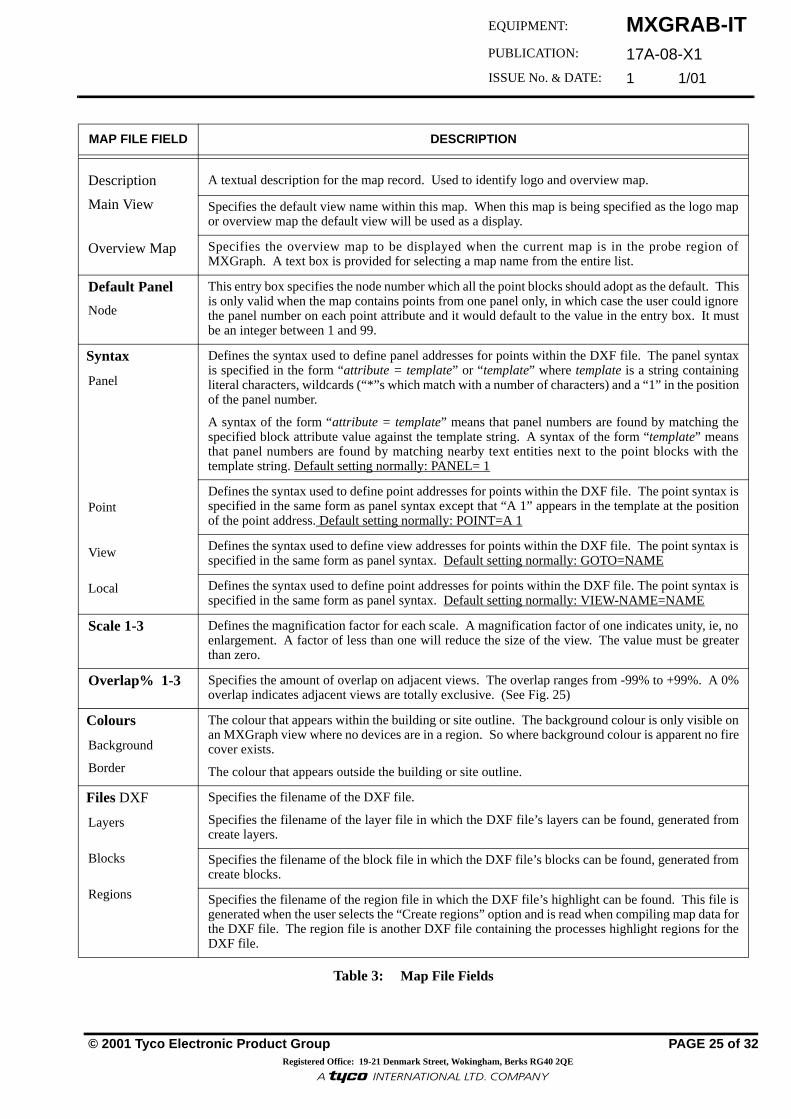
MAP FILE FIELD DESCRIPTION
Description
Main View
Overview Map
A textual description for the map record. Used to identify logo and overview map.
Specifies the default view name within this map. When this map is being specified as the logo mapor overview map the default view will be used as a display.
Specifies the overview map to be displayed when the current map is in the probe region ofMXGraph. A text box is provided for selecting a map name from the entire list.
Default Panel
Node
This entry box specifies the node number which all the point blocks should adopt as the default. Thisis only valid when the map contains points from one panel only, in which case the user could ignorethe panel number on each point attribute and it would default to the value in the entry box. It mustbe an integer between 1 and 99.
Syntax
Panel
Point
View
Local
Defines the syntax used to define panel addresses for points within the DXF file. The panel syntaxis specified in the form “attribute = template” or “ template” where template is a string containingliteral characters, wildcards (“*”s which match with a number of characters) and a “1” in the positionof the panel number.
A syntax of the form “attribute = template” means that panel numbers are found by matching thespecified block attribute value against the template string. A syntax of the form “template” meansthat panel numbers are found by matching nearby text entities next to the point blocks with thetemplate string. Default setting normally: PANEL= 1
Defines the syntax used to define point addresses for points within the DXF file. The point syntax isspecified in the same form as panel syntax except that “A 1” appears in the template at the positionof the point address. Default setting normally: POINT=A 1
Defines the syntax used to define view addresses for points within the DXF file. The point syntax isspecified in the same form as panel syntax. Default setting normally: GOTO=NAME
Defines the syntax used to define point addresses for points within the DXF file. The point syntax isspecified in the same form as panel syntax. Default setting normally: VIEW-NAME=NAME
Scale 1-3 Defines the magnification factor for each scale. A magnification factor of one indicates unity, ie, noenlargement. A factor of less than one will reduce the size of the view. The value must be greaterthan zero.
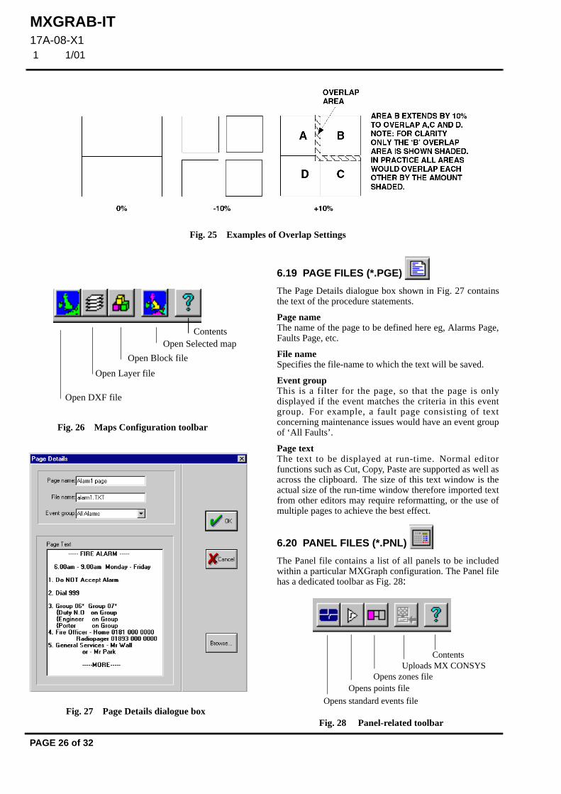
Overlap% 1-3 Specifies the amount of overlap on adjacent views. The overlap ranges from -99% to +99%. A 0%overlap indicates adjacent views are totally exclusive. (See Fig. 25)
Colours
Background
Border
The colour that appears within the building or site outline. The background colour is only visible onan MXGraph view where no devices are in a region. So where background colour is apparent no firecover exists.
The colour that appears outside the building or site outline.
Files DXF
Layers
Blocks
Regions
Specifies the filename of the DXF file.
Specifies the filename of the layer file in which the DXF file’s layers can be found, generated fromcreate layers.
Specifies the filename of the block file in which the DXF file’s blocks can be found, generated fromcreate blocks.
Specifies the filename of the region file in which the DXF file’s highlight can be found. This file isgenerated when the user selects the “Create regions” option and is read when compiling map data forthe DXF file. The region file is another DXF file containing the processes highlight regions for theDXF file.
Table 3: Map File Fields
MXGRAB-IT17A-08-X1 1 1/01
PAGE 26 of 32
Fig. 25 Examples of Overlap Settings
Fig. 26 Maps Configuration toolbar
Open DXF file
Open Layer file
Open Block file
Open Selected mapContents
Fig. 27 Page Details dialogue box
6.19 PAGE FILES (*.PGE)
The Page Details dialogue box shown in Fig. 27 containsthe text of the procedure statements.
Page name The name of the page to be defined here eg, Alarms Page,Faults Page, etc.
File name Specifies the file-name to which the text will be saved.
Event group This is a filter for the page, so that the page is onlydisplayed if the event matches the criteria in this eventgroup. For example, a fault page consisting of textconcerning maintenance issues would have an event groupof ‘All Faults’.
Page text The text to be displayed at run-time. Normal editorfunctions such as Cut, Copy, Paste are supported as well asacross the clipboard. The size of this text window is theactual size of the run-time window therefore imported textfrom other editors may require reformatting, or the use ofmultiple pages to achieve the best effect.
6.20 PANEL FILES (*.PNL)
The Panel file contains a list of all panels to be includedwithin a particular MXGraph configuration. The Panel filehas a dedicated toolbar as Fig. 28:
ContentsUploads MX CONSYS
Opens zones fileOpens points file
Opens standard events file
Fig. 28 Panel-related toolbar

MXGRAB-IT17A-08-X1
1 1/01
© 2001 Tyco Electronic Product Group PAGE 27 of 32Registered Office: 19-21 Denmark Street, Wokingham, Berks RG40 2QE
EQUIPMENT:
PUBLICATION:
ISSUE No. & DATE:
«¥����¥³¸¾¯¼¸«¾³¹¸«¶¥¶¾®�¥¹·º«¸Ã
Fig. 29 ‘Panel Details’ dialogue box has the following fields:
Number The node number of the panel.
Type Specifies the type of panel, MX or PC.
Events Specifies the filename of an event file. This defines thedefault event code interpretations for points belonging tothis panel. The file should contain a record for each possibleMX event code. (Shorter event files can be used to definesub-sets of event codes which are used to override thisdefault event file on a category by category basis).
Points Specifies the filename of a points file. For MX CONSYSimported data this file is generated automatically and theentry remains read only. A default MXPC.PNT is providedfor the MXGraph node.
Zones Specifies the filename of a zone file. For MX CONSYSimported data this file is generated automatically and theentry remains read only. A MXTG.ZON file is provided forMXGraph node.
6.20.1 UPLOAD MX CONSYS
Fig. 30 ‘Upload Behaviour Preferences’ dialogue box contains the following tickboxes:
‘Allow overwrite with blank point descriptions’
The Description field for each point uploaded from the MXCONSYS data will always be set to the description in thedata, unless this box is not ticked and the MX CONSYS datahas no description of the point. In this case, the existingdescription in the Point File will be retained and not beoverwritten with the blank description.
Fig. 29 Panel Details dialogue box
‘If description changed - Reset event details’
When this box is ticked, any event which already exists inthe Event File but whose event description has changed willhave its event desciption changed to the new setting, itsclassification set to ‘Unclassified’, its priority and eventclass changed to ‘Information’.
6.21 PRINTER CONFIGURATION FILE (*.PRT)
The Printer Configuration file specifies the names of anyWindows NT4.0 printer to be used for hardcopy output fromMXGraph.
Printer Name Specifies the name of a Windows NT4.0 printer configuredon the MXGraph PC.
Event Status Group The name of an event status group used to filter eventsbefore sending them to the printer. Only events meeting theevent status group’s selection criteria will be printed.
Fig. 30 Upload Behaviour Preferences
Fig. 31 Printer dialogue box

MXGRAB-IT17A-08-X1 1 1/01
PAGE 28 of 32
Live Events Specifies whether or not events in the event status group willbe printed to this printer as they arrive.
Acceptance Specifies whether or not events in the event status group willbe printed to this printer as they are accepted.
Procedures Specifies whether or not procedures are printed to thisprinter.
Reports Specifies whether or not point status reports or event listreports will be sent to this printer.
A dialogue box is provided to enable selection of the printerand the items to be printed in Fig. 31.
6.22 PRIORITY FILES (*.PRI)
The Priority file is used to define the relative importance ofevents or point states and to assign a colour and sound toeach level of importance.
A typical Priority Details dialogue box is shown in Fig. 32,with the ‘Change colour’ displayed in Fig. 33:
Fig. 32 Priority Details dialogue box
Fig. 33 Change colour dialogue box
Priority The name of the priority. This name is referred to fromother files.
Sound Specifies the name of a sound to be played when the highestpriority unaccepted event has this priority.
Ranking A numerical value assigned to this priority which definestheir relative order. The higher the ranking, the moreimportant the priority.
Colour Specifies the colour allocated to this priority. The colour isused to draw the background when listing point states, or tocolour highlight areas on maps.
Associated with each priority description is the colour,sound and priority ranking. The default list is described inTable 4:
Change colour Use the colourbox/paintbox as provided by the Windowsenvironment, to change a background colour. Use the ‘Addto Custom Colors’ button to save customised colours.
During run-time the MXGraph event manager derives thebackground colour from the event priority level specified inthe event file (*.EVT), so Event Priority editing can be doneat source level. The windows using this priority level at run-time are Event Banner and Event Listing.
The background colour of a point status is determined by thecategory to which it belongs. Since each category hasseparate entries for priority, the colour and sound for statuscan be different from the events. The windows which usethis scheme at run-time are, Status listing, Highlights onmaps, and Overview window.
DESCRIPTION RANK COLOUR SOUND
Life risk 13 Red Evacuate
Non-life risk 11 Red Alarm
Latched Alarm 10 Red Alarm
Pre-Alarm 9 Pink Pre-Alarm
Critical Fault 8 Yellow Fault
Fault 7 Yellow Fault
Warning 6 Blue Warning
Test 5 Green Test
Day 4 White Warning
Isolated 4 Cyan Isolated
Expected 3 White OK
Night 3 Black Warning
Information 1 White OK
Table 4:

MXGRAB-IT17A-08-X1
1 1/01
© 2001 Tyco Electronic Product Group PAGE 29 of 32Registered Office: 19-21 Denmark Street, Wokingham, Berks RG40 2QE
EQUIPMENT:
PUBLICATION:
ISSUE No. & DATE:
«¥����¥³¸¾¯¼¸«¾³¹¸«¶¥¶¾®�¥¹·º«¸Ã
6.23 PROCEDURE FILES (*.PRC)
The Procedure f i le spec i f ies the types of pagesavailable. Each procedure page will consist of one or morepages of text, as shown in Fig. 34:
Procedure The name of the procedure to be defined.
Page List A list of all the available pages defined in the page file. Theleft/right arrows are used to add or remove pages to/from thePage List.
Chosen Pages A listing of all the pages chosen from the pager list whichare to be included in the procedure. The up/down arrows areused to arrange the order of the pages.
6.24 POINT FILES (*.PNT)
Point files are used to specify point descriptions for all thepoints which are either imported from MX CONSYS data orMXGraph data. Fig. 35 is displayed in both cases.
Address The point address being defined (eg, LIO P14).
Zone The zone number containing the defined point.
Device The type of device at the defined point (eg, 801PH, this isread only if imported from MX CONSYS).
Base Choose between None, Sounder, Relay, Isolator, Isolator &Sounder or Isolator & Relay options.
Style Choose from the options based on the Styles file.
Fig. 34 Procedure Details dialogue box
Procedure The procedure associated with the point.
Description This is a textual description of the point imported.
Text 1 (Optional) The first line of additional descriptive text which can bedisplayed along with the point details in the Alert Bannerof MXGraph.
Text 2 (Optional) The second line of additional descriptive text which can bedisplayed (in addition to Text 1) along with the pointdetails in the Alert Banner of MXGraph.
Fig. 35 Point Details dialogue box
MXGRAB-IT17A-08-X1 1 1/01
PAGE 30 of 32
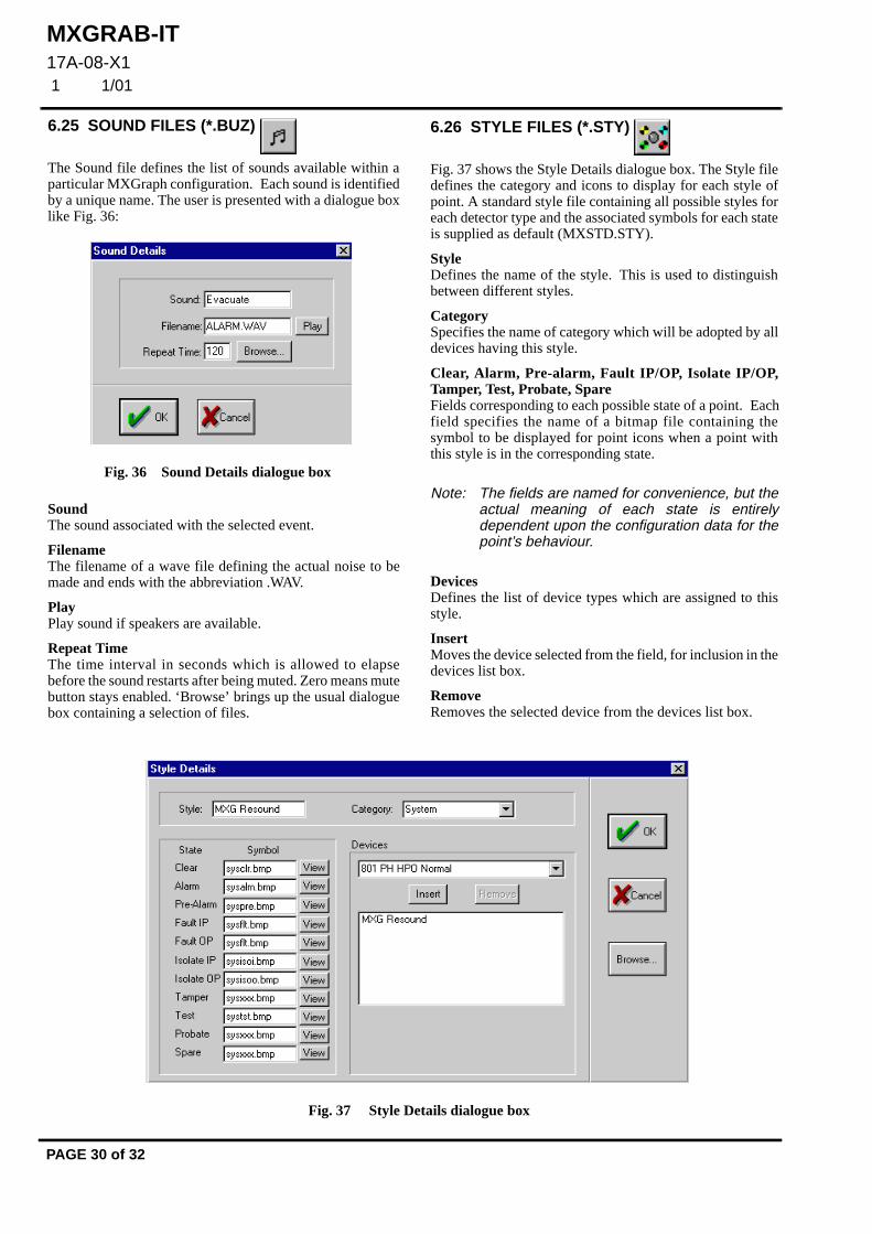
Fig. 37 Style Details dialogue box
6.25 SOUND FILES (*.BUZ)
The Sound file defines the list of sounds available within aparticular MXGraph configuration. Each sound is identifiedby a unique name. The user is presented with a dialogue boxlike Fig. 36:
Sound The sound associated with the selected event.
Filename The filename of a wave file defining the actual noise to bemade and ends with the abbreviation .WAV.
Play Play sound if speakers are available.
Repeat Time The time interval in seconds which is allowed to elapsebefore the sound restarts after being muted. Zero means mutebutton stays enabled. ‘Browse’ brings up the usual dialoguebox containing a selection of files.
Fig. 36 Sound Details dialogue box
6.26 STYLE FILES (*.STY)
Fig. 37 shows the Style Details dialogue box. The Style filedefines the category and icons to display for each style ofpoint. A standard style file containing all possible styles foreach detector type and the associated symbols for each stateis supplied as default (MXSTD.STY).
Style Defines the name of the style. This is used to distinguishbetween different styles.
Category Specifies the name of category which will be adopted by alldevices having this style.
Clear, Alarm, Pre-alarm, Fault IP/OP, Isolate IP/OP,Tamper, Test, Probate, Spare Fields corresponding to each possible state of a point. Eachfield specifies the name of a bitmap file containing thesymbol to be displayed for point icons when a point withthis style is in the corresponding state.
Note: The fields are named for convenience, but theactual meaning of each state is entirelydependent upon the configuration data for thepoint’s behaviour.
Devices Defines the list of device types which are assigned to thisstyle.
Insert Moves the device selected from the field, for inclusion in thedevices list box.
Remove Removes the selected device from the devices list box.

MXGRAB-IT17A-08-X1
1 1/01
© 2001 Tyco Electronic Product Group PAGE 31 of 32Registered Office: 19-21 Denmark Street, Wokingham, Berks RG40 2QE
EQUIPMENT:
PUBLICATION:
ISSUE No. & DATE:
«¥����¥³¸¾¯¼¸«¾³¹¸«¶¥¶¾®�¥¹·º«¸Ã
6.27 TARGET GROUPS (*.GRP)
This file holds the group name and group number of thegroups used in MX CONSYS. Target Groups files can onlybe viewed they cannot be modified by the user. These filesare completely rebuilt every time an MX CONSYS uploadis performed.
6.28 USER FILES (*.USR)
This file identifies the set of users who can log ontoMXGraph. Users are presented with the dialogue box as Fig. 38:
Name The name of the user which will be displayed when the useris logged on or when displaying who has accepted an event.
Passcode A number which must be entered to allow the user to log onto MXGraph. Each user must have a unique passcode. Thepasscode consists of a 8-digit number ranging from 1 to99999999. Leading zeros will be discarded as the numberwill be interpreted as an integer.
Level The name of the access level defining the commands whichthe user is permitted to use.
6.29 ZONE FILES (*.ZON)
Note: Zone file data created by an MX CONSYSupload is read only. For MXGraph panels thezone details can be edited.
Fig. 38 User Details dialogue box
Zone The zone number from MX CONSYS. Panel devices areassigned to a zone number. Zone numbers range from 0 to240. Zones 1 to 240 can represent the site area.
Network zone Fig. 39 shows the ‘Network zone’ link number loaded fromMX CONSYS displayed as 1. This is optional for a zoneassigned to a Network zone. MXGraph has to state theNetwork zone number to control the panel point. Networkzone numbers range from 0 to 250. Value 251 means a zonenot in a Network zone.
Remote and adjacent panel zones can be linked together byMX CONSYS with the Network zone link.
Sector Select ‘Sector’ number (1 upto 254). Value 254 means zonenot in a sector.
Zone Description Zone Description is the network zone description if the zoneis in a network OR it is the zone description, if it is not.
Sector Description The Sector Description.
7. MAPS CONFIGURATIONMaps configuration extracts pre-configured, embeddedinformation from a given DXF file. The embedded datashould have been input to the DXF file by the CADoperator. The data process for a raw DXF file through to acompliant DXF file for use by MXGRAB-IT is illustrated inFig. 40:
Fig. 39 Zone Details dialogue box

MXGRAB-IT17A-08-X1 1 1/01
PAGE 32 of 32
Fig. 40 DXF File Data Process
7.1 CONFIGURATION OVERVIEW
1) The configuration process for maps issummarised in the following steps: Draw ormodify the given map using the AutoCADsoftware.
Note: It is assumed that the required data is on theDXF file and has been entered by the CADoperator using the conventions developed formap production.
2) Export the completed map from AutoCAD inDXF format to MXGRAB-IT.
3) Add information such as ZOOM factors,overlap areas, etc (if not already added). Anew DXF file with the added information isgenerated.
(This new DXF file can be fed back toAutoCAD for inspecting/checking if required,or can be previewed in MXGRAB-IT).
4) If a DXF file does not have the zoomboundary or navigation buttons defined,M X G R A B - I T w i l l g en e r a t e t h e mautomatically. The following information isrequired to be input:
• The magnification factor for eachzoom level
• The percentage overlap between twoadjacent child maps
• The number of zoom levels (max. 3)
5) MXGRAB-IT generates the zoom boxes(AutoCAD blocks) on the $VIEW-n layersand pre-allocates the navigation buttons(AutoCAD blocks) for adjacent maps.
6) The navigation buttons are pre-assigned toshow the direction of the next map in theseries, if a button has no adjacent map then itis not configured.
7) The zoom maps may be previewed withoutproducing a database.
8) When the configuration data has beenentered, the MXGRAB- IT programcompiles the database files. Any errorsfound during input or compilation are loggedto a text file titled ‘Report.TXT’ in thec:\temp directory.
CB/pl
10th January 2001
MXGRAB-IT17A-08-X1 APP A
1 1/01
© 2001 Tyco Electronic Product Group PAGE 1 of 4Registered Office: 19-21 Denmark Street, Wokingham, Berks RG40 2QE
EQUIPMENT:
PUBLICATION:
ISSUE No. & DATE:
«¥����¥³¸¾¯¼¸«¾³¹¸«¶¥¶¾®�¥¹·º«¸Ã
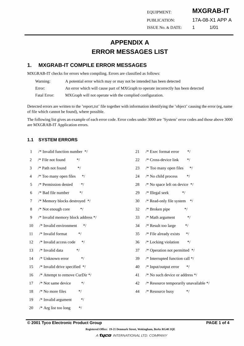
APPENDIX A ERROR MESSAGES LIST
1. MXGRAB-IT COMPILE ERROR MESSAGESMXGRAB-IT checks for errors when compiling. Errors are classified as follows:
Warning: A potential error which may or may not be intended has been detected
Error: An error which will cause part of MXGraph to operate incorrectly has been detected
Fatal Error: MXGraph will not operate with the complied configuration.
Detected errors are written to the ’report,txt’ file together with information identifying the ’object’ causing the error (eg, nameof file which cannot be found), where possible.
The following list gives an example of each error code. Error codes under 3000 are ’System’ error codes and those above 3000are MXGRAB-IT Application errors.
1.1 SYSTEM ERRORS
1 /* Invalid function number */ 21 /* Exec format error */
2 /* File not found */ 22 /* Cross-device link */
3 /* Path not found */ 23 /* Too many open files */
4 /* Too many open files */ 24 /* No child process */
5 /* Permission denied */ 28 /* No space left on device */
6 /* Bad file number */ 29 /* Illegal seek */
7 /* Memory blocks destroyed */ 30 /* Read-only file system */
8 /* Not enough core */ 32 /* Broken pipe */
9 /* Invalid memory block address */ 33 /* Math argument */
10 /* Invalid environment */ 34 /* Result too large */
11 /* Invalid format */ 35 /* File already exists */
12 /* Invalid access code */ 36 /* Locking violation */
13 /* Invalid data */ 37 /* Operation not permitted */
14 /* Unknown error */ 39 /* Interrupted function call */
15 /* Invalid drive specified */ 40 /* Input/output error */
16 /* Attempt to remove CurDir */ 41 /* No such device or address */
17 /* Not same device */ 42 /* Resource temporarily unavailable */
18 /* No more files */ 44 /* Resource busy */
19 /* Invalid argument */
20 /* Arg list too long */

MXGRAB-IT17A-08-X1 APP A 1 1/01
PAGE 2 of 4
1.2 APPLICATION ERRORS
ERR3001 - Error: In C:\SUMMIT\SUMMIT.MAP Map(TITLE) : Default map appears more than once
ERR3002 - Error: In C:\SUMMIT\SUMMIT.MAP Map(TITLE) : Default map not found
ERR3003 - Error: C:\SUMMIT\SUMMIT.MAP Map : Too many maps (maximum is 200)
ERR3004 - Optional Warning: Device type (801I Low) : Style is not unique
ERR3006 - Error: Device type(I/P (RIM 800) : Can’t find any style
ERR3007 - Error: Unknown comms port specified. Using default(COM1:)
ERR3008 - Error: Invalid local node address
ERR3009 - Warning: No panel configuration for local node
ERR3010 - Error: Invalid node address for event logging
ERR3011 - Warning: Procedure(French) : No pages configured
ERR3012 - Error: In Procedure Page(Faults page): Can’t find this in the page file
ERR3013 - Fatal: page0(alarm.TXT) : Overlong string
ERR3014 - Error: In Procedure Page(Testpage4) : No event status group specified
ERR3015 - Error: Invalid country found. Using default(UK)
ERR3016 - Warning: Overview logo bitmap file not specified
ERR3017 - Error: Can’t retrieve Grab-It version information
ERR3018 - Warning: In Panel 10 Point(A 101) : This point is not on any map
ERR3021 - Error: In C:\TESTBORD\TESTBORD.PNL Panel(1) : Unknown panel type
ERR3022 - Fatal: In Panel 1 POINT1.PNT Zone(0) : Invalid zone number
ERR3023 - Error: In Panel 1 POINT1.PNT Address(A 1) : Invalid address
ERR3024 - Error: In Panel 1 ZONE1.ZON Zone(0) : Repeated zone number
ERR3025 - Error: In Panel 1 ZONE1.ZON Zone(1) : Missing zone number
ERR3026 - Error: In POINT1.PNT Address A 2 Procedure(German) : Procedure not in STDPROC.PRC
ERR3027 - Warning: In POINT1.PNT Address(A 1) : Missing procedure
ERR3030 - Error: Critical Fault : Priority not found
ERR3031 - Error: Zone (1) in table (e:\summitMX\MXPC.ZON) uses sector which is not in the range 0 to 240 or 254
ERR3032 - Error: Callpoint : Can not find style for device type (Call point)
ERR3033 - Error: In Danger Status All isolates Active icon(c:\testbord\DS_FIRE.BMP) : Can’t create bitmap from thisicon file
ERR3034 - Warning: In Danger Status Fire alarms Active icon(c:\testbord\DS_FIRE.BMP) : Different size to inactive icon
ERR3035 - Warning: In Danger Status All isolates Active icon(c:\testbord\DS_FIRE.BMP) : Too tall to fit in Danger Status Bar
ERR3036 - Warning: In Danger Status All isolates Active icon(c:\testbord\DS_FIRE.BMP) : Falls outside of the DangerStatus Bar left border
ERR3037 - Warning: In Danger Status All isolates Active icon(c:\testbord\DS_FIRE.BMP) : Falls outside of the DangerStatus Bar right border
ERR3038 - Warning: In Danger Status Fire alarms Inactive icon(c:\testbord\DS_FIRE.BMP) : Overlaps a previous bitmap
ERR3039 - Warning: Danger status not found : All faults
ERR3040 - Error: All Events : Event status group not found
ERR3041 - Error: In C:\TESTBORD\EVENT1.EVT Event Code(239) : Invalid event code
ERR3042 - Error: In C:\TESTBORD\MINADD.EVT Event Code(250) : Duplicate event code
ERR3043 - Error: c:\testbord\DS_FIRE.BMP : Too many colours in this bitmap
ERR3044 - Error: In C:\TESTBORD\TRILATCH.BHV Behaviour(Reset) : Duplicate behaviour entry found
ERR3045 - Error: Sound 1 : Sound not found
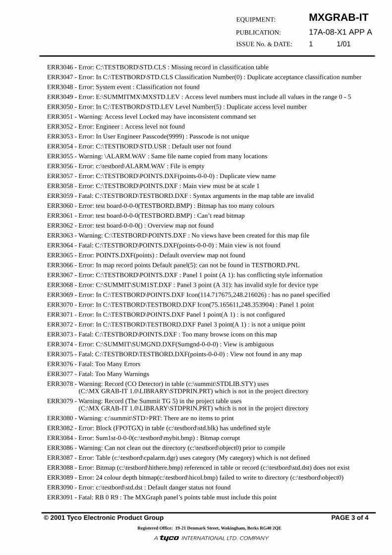
MXGRAB-IT17A-08-X1 APP A
1 1/01
© 2001 Tyco Electronic Product Group PAGE 3 of 4Registered Office: 19-21 Denmark Street, Wokingham, Berks RG40 2QE
EQUIPMENT:
PUBLICATION:
ISSUE No. & DATE:
«¥����¥³¸¾¯¼¸«¾³¹¸«¶¥¶¾®�¥¹·º«¸Ã
ERR3046 - Error: C:\TESTBORD\STD.CLS : Missing record in classification table
ERR3047 - Error: In C:\TESTBORD\STD.CLS Classification Number(0) : Duplicate acceptance classification number
ERR3048 - Error: System event : Classification not found
ERR3049 - Error: E:\SUMMITMX\MXSTD.LEV : Access level numbers must include all values in the range 0 - 5
ERR3050 - Error: In C:\TESTBORD\STD.LEV Level Number(5) : Duplicate access level number
ERR3051 - Warning: Access level Locked may have inconsistent command set
ERR3052 - Error: Engineer : Access level not found
ERR3053 - Error: In User Engineer Passcode(9999) : Passcode is not unique
ERR3054 - Error: C:\TESTBORD\STD.USR : Default user not found
ERR3055 - Warning: \ALARM.WAV : Same file name copied from many locations
ERR3056 - Error: c:\testbord\ALARM.WAV : File is empty
ERR3057 - Error: C:\TESTBORD\POINTS.DXF(points-0-0-0) : Duplicate view name
ERR3058 - Error: C:\TESTBORD\POINTS.DXF : Main view must be at scale 1
ERR3059 - Fatal: C:\TESTBORD\TESTBORD.DXF : Syntax arguments in the map table are invalid
ERR3060 - Error: test board-0-0-0(TESTBORD.BMP) : Bitmap has too many colours
ERR3061 - Error: test board-0-0-0(TESTBORD.BMP) : Can’t read bitmap
ERR3062 - Error: test board-0-0-0() : Overview map not found
ERR3063 - Warning: C:\TESTBORD\POINTS.DXF : No views have been created for this map file
ERR3064 - Fatal: C:\TESTBORD\POINTS.DXF(points-0-0-0) : Main view is not found
ERR3065 - Error: POINTS.DXF(points) : Default overview map not found
ERR3066 - Error: In map record points Default panel(5): can not be found in TESTBORD.PNL
ERR3067 - Error: C:\TESTBORD\POINTS.DXF : Panel 1 point (A 1): has conflicting style information
ERR3068 - Error: C:\SUMMIT\SUM1ST.DXF : Panel 3 point (A 31): has invalid style for device type
ERR3069 - Error: In C:\TESTBORD\POINTS.DXF Icon(114.717675,248.216026) : has no panel specified
ERR3070 - Error: In C:\TESTBORD\TESTBORD.DXF Icon(75.165611,248.353904) : Panel 1 point
ERR3071 - Error: In C:\TESTBORD\POINTS.DXF Panel 1 point(A 1) : is not configured
ERR3072 - Error: In C:\TESTBORD\TESTBORD.DXF Panel 3 point(A 1) : is not a unique point
ERR3073 - Fatal: C:\TESTBORD\POINTS.DXF : Too many browse icons on this map
ERR3074 - Error: C:\SUMMIT\SUMGND.DXF(Sumgnd-0-0-0) : View is ambiguous
ERR3075 - Fatal: C:\TESTBORD\TESTBORD.DXF(points-0-0-0) : View not found in any map
ERR3076 - Fatal: Too Many Errors
ERR3077 - Fatal: Too Many Warnings
ERR3078 - Warning: Record (CO Detector) in table (c:\summit\STDLIB.STY) uses (C:\MX GRAB-IT 1.0\LIBRARY\STDPRIN.PRT) which is not in the project directory
ERR3079 - Warning: Record (The Summit TG 5) in the project table uses (C:\MX GRAB-IT 1.0\LIBRARY\STDPRIN.PRT) which is not in the project directory
ERR3080 - Warning: c:\summit\STD>PRT: There are no items to print
ERR3082 - Error: Block (FPOTGX) in table (c:\testbord\std.blk) has undefined style
ERR3084 - Error: Sum1st-0-0-0(c:\testbord\mybit.bmp) : Bitmap corrupt
ERR3086 - Warning: Can not clean out the directory (c:\testbord\object0) prior to compile
ERR3087 - Error: Table (c:\testbord\cpalarm.dgr) uses category (My category) which is not defined
ERR3088 - Error: Bitmap (c:\testbord\hithere.bmp) referenced in table or record (c:\testbord\std.dst) does not exist
ERR3089 - Error: 24 colour depth bitmap(c:\testbord\hicol.bmp) failed to write to directory (c:\testbord\object0)
ERR3090 - Error: c:\testbord\std.dst : Default danger status not found
ERR3091 - Fatal: RB 0 R9 : The MXGraph panel’s points table must include this point

MXGRAB-IT17A-08-X1 APP A 1 1/01
PAGE 4 of 4
ERR3092 - Warning : c:\testbord\std.dxf (A 923) Address in the DXF is invalid
ERR3093 - Warning : c:\testbord\testbord.usr : User with blank name
ERR3094 - Warning : MXG Evacuate : The control table should cover this style
ERR3095 - Error: c:\testbord\mx.evt : Open fault, can’t check event codes used in Control Table
ERR3096 - Error: Event code (234) used in the record (MXG Day Mode) of Control Table is not covered by the Event Table
ERR3097 - Warning : In c:\testbord\mx.evt Event Code(7) : Missing event code
ERR3098 - Error: More than one node is configured for broadcast
ERR3099 - More than 100 users in c:\testbord\std.usr
ERR3100 - Control Table uses group (123) not covered by Target Groups table (c:\testbord\mxstd.grp)
ERR3101 - Error: Event Logging node (45) is not in the subnet
ERR3102 - Error: Event Logging node (1) is duplicated
ERR3103 - Fatal: File (e:\summitMX\CONTROL.BLK) could not be opened.
CB/pl
10th January 2001
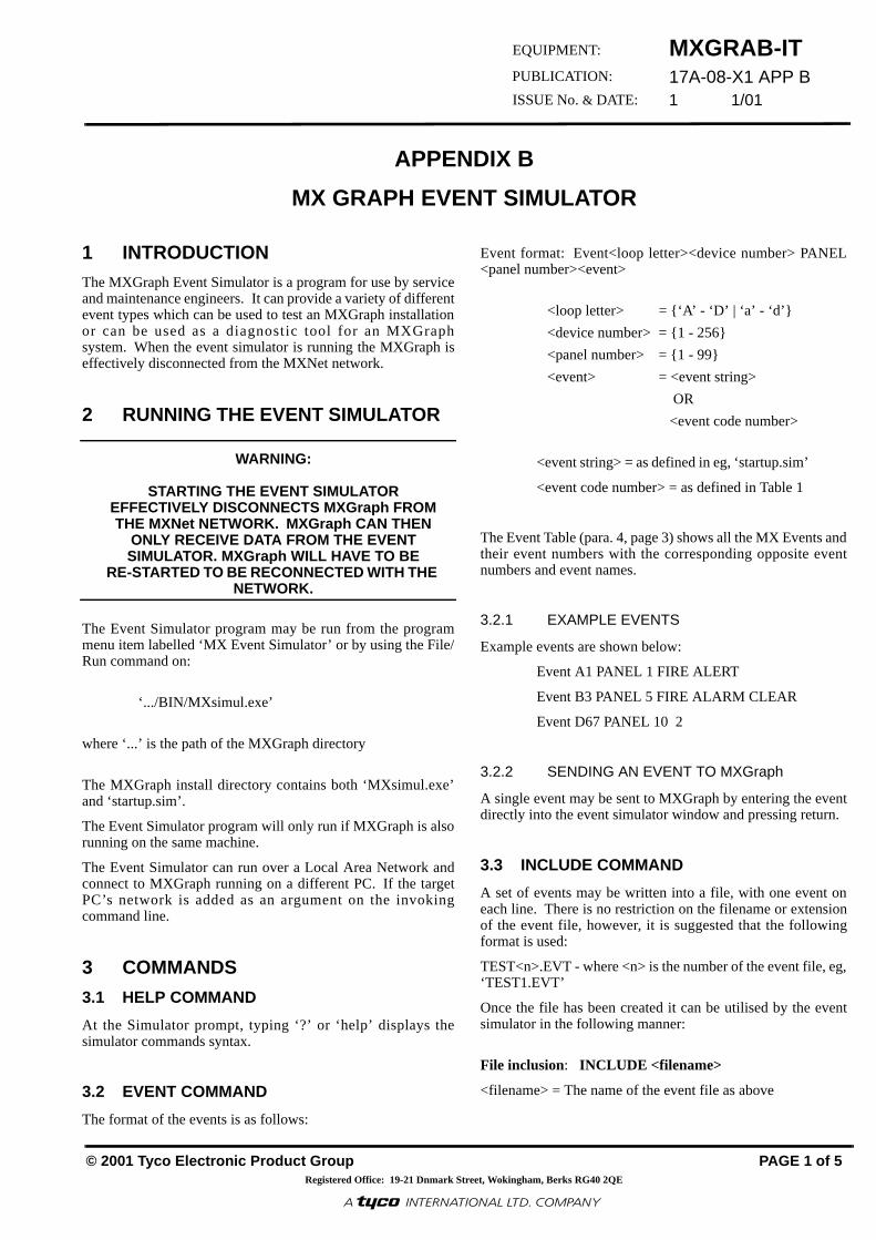
© 2001 Tyco Electronic Product Group PAGE 1 of 5
MXGRAB-IT17A-08-X1 APP B1 1/01
Registered Office: 19-21 Dnmark Street, Wokingham, Berks RG40 2QE
EQUIPMENT:
PUBLICATION:
ISSUE No. & DATE:
«¥����¥³¸¾¯¼¸«¾³¹¸«¶¥¶¾®�¥¹·º«¸Ã
APPENDIX B
MX GRAPH EVENT SIMULATOR
1 INTRODUCTIONThe MXGraph Event Simulator is a program for use by serviceand maintenance engineers. It can provide a variety of differentevent types which can be used to test an MXGraph installationor can be used as a diagnostic tool for an MXGraphsystem. When the event simulator is running the MXGraph iseffectively disconnected from the MXNet network.
2 RUNNING THE EVENT SIMULATOR
WARNING:
STARTING THE EVENT SIMULATOR EFFECTIVELY DISCONNECTS MXGraph FROM THE MXNet NETWORK. MXGraph CAN THEN
ONLY RECEIVE DATA FROM THE EVENT SIMULATOR. MXGraph WILL HAVE TO BE
RE-STARTED TO BE RECONNECTED WITH THE NETWORK.
The Event Simulator program may be run from the programmenu item labelled ‘MX Event Simulator’ or by using the File/Run command on:
‘.../BIN/MXsimul.exe’
where ‘...’ is the path of the MXGraph directory
The MXGraph install directory contains both ‘MXsimul.exe’and ‘startup.sim’.
The Event Simulator program will only run if MXGraph is alsorunning on the same machine.
The Event Simulator can run over a Local Area Network andconnect to MXGraph running on a different PC. If the targetPC’s network is added as an argument on the invokingcommand line.
3 COMMANDS
3.1 HELP COMMAND
At the Simulator prompt, typing ‘?’ or ‘help’ displays thesimulator commands syntax.
3.2 EVENT COMMAND
The format of the events is as follows:
Event format: Event<loop letter><device number> PANEL<panel number><event>
<loop letter> = {‘A’ - ‘D’ | ‘a’ - ‘d’}
<device number> = {1 - 256}
<panel number> = {1 - 99}
<event> = <event string>
OR
<event code number>
<event string> = as defined in eg, ‘startup.sim’
<event code number> = as defined in Table 1
The Event Table (para. 4, page 3) shows all the MX Events andtheir event numbers with the corresponding opposite eventnumbers and event names.
3.2.1 EXAMPLE EVENTS
Example events are shown below:
Event A1 PANEL 1 FIRE ALERT
Event B3 PANEL 5 FIRE ALARM CLEAR
Event D67 PANEL 10 2
3.2.2 SENDING AN EVENT TO MXGraph
A single event may be sent to MXGraph by entering the eventdirectly into the event simulator window and pressing return.
3.3 INCLUDE COMMAND
A set of events may be written into a file, with one event oneach line. There is no restriction on the filename or extensionof the event file, however, it is suggested that the followingformat is used:
TEST<n>.EVT - where <n> is the number of the event file, eg,‘TEST1.EVT’
Once the file has been created it can be utilised by the eventsimulator in the following manner:
File inclusion: INCLUDE <filename>
<filename> = The name of the event file as above

MXGRAB-IT
17A-08-X1 APP B
1 1/01
PAGE 2 of 5
Note: If the Event Simulator discovers a syntax errorin the file, it will stop immediately.
3.4 DUMP COMMAND
DUMP <ON/OFF> When dump is on, information about packets is dumped tothe simulator console.
3.5 TIME COMMAND
TIME sets the date/time on the MXGraph PC to the same asthe simulator PC. This command has TWO formats:
Time Panel <panel> Synchronise Synchronise MXGraph time with simulator PC time.
Time Panel <panel> <+/-hours> Offset MXGraph time by hours (-9 to +9 hours)
3.6 DESCRIBE COMMAND
DESCRIBE requests point and/or zone description stringsfrom MXGraph. This command has THREE formats:
Describe <uad> Panel <panel> Get point description only
Describe <uad> Panel <panel> Zone <zone> Get zone description only
Describe <uad> Panel <panel> All <zone> Get point and zone description
3.7 ISOLATE COMMAND
ISOLATE controls what replies will be sent to MXGraphwhen it sends requests for isolate states. This command hasTWO formats:
Isolate off No reply will be sent
Isolate on nnn nnn will be used in every status byte of the reply
3.8 END COMMAND
Closes the simulator
3.9 SLEEP COMMAND
SLEEP <X> pauses the simulator for x 100ths of a second
3.10 LOOP COMMAND
LOOP loops to the beginning of the INCLUDE file (See INCLUDE command)
3.11 CODE COMMAND
CODE <event code number> <event code name>
The user can associate a string with an event code number sothat the string can be used instead of the event code whenusing the EVENT command.
3.12 SUPERVISION REPLY PANEL COMMAND
SUPERVISION REPLY PANEL <panel> <Y/N>
This allows/disallows the simulator from replying tosupervision packets from MXGraph.
3.13 RESET COMMAND
RESET PANEL <panel>
This command sends a log event to MXGraph
3.14 RESETALL COMMAND
This command performs a Silence-Reset

MXGRAB-IT17A-08-X1 APP B1 1/01
© 2001 Tyco Electronic Product Group PAGE 3 of 5
Registered Office: 19-21 Denmark Street, Wokingham, Berks RG40 2QE
EQUIPMENT:
PUBLICATION:
ISSUE No. & DATE:
«¥����¥³¸¾¯¼¸«¾³¹¸«¶¥¶¾®�¥¹·º«¸Ã
4 EVENT TABLE
Note: Entries in bold type and marked with an asterisk(*) are those most likely to be needed for MXGraphtests.
EVENT No.
OPPOSITEEVENT No
EVENT NAME
000 N/A INVALID
001 001 IGNORE/NO ACTION
002 CLEAR
003 <Not Used>
004 PRE-ALARM
005 ALARM VERIFYING
006 ALARM INPUT ACTIVE
007 FAULT CLEAR
*008 007 NO RESPONSE
009 HIGH IDENT CURRENT
010 LOW IDENT CURRENT
011 IDENT FAULT
012 MULTIPLE DEVICES
*013 DEVICE FAULT
014 WIRING FAULT
015 WIRING O/C FAULT
016 WIRING S/C FAULT
017 INVALID CONDITION
018 NOISY DEVICE
019 PSU CHARGER FAULT
020 UNCONFIGURED DEVICE
021 MAINS FAULT
*022 001 FIRE ALARM CLEAR
*023 022 FIRE ALERT
024 FIRE EVACUATE
025 FIRE GAS RELEASE
026 002 FIRE ALARM
027 CALLPOINT ALERT
028 CALLPOINT EVACUATE
029 <Not Used>
030 007 LOOP FAULT SHUTDOWN
031 GROUND FAULT
032 <Not Used>
033 <Not Used>
034 <Not Used>
035 036 SIG DELAY ENABLED
036 035 SIG DELAY DISABLED
037 002 MEDICAL ALERT
038 ISOLATE WARNING
039 COINCIDENCE WARNING
040 DELAY STARTED
041 FIRE ALARM WARNING
042 043 ISOLATE IN SYSTEM
043 042 SYSTEM DE-ISOLATED
044 <Not Used>
045 046 NIGHT MODE
046 045 DAY MODE
047 002 WEEKLY TEST REMIND
048 FIRE TEST ALARM
049 <Not Used>
050 051 TEST STARTED
051 050 TEST FINISHED
052 002 POINT TESTED
053 POINT (WW) TESTED
054 007 LO L. TERM AVG FAULT
055 HI L. TERM AVG FAULT
056 LOOP O/C FAULT
057 LOOP S/C FAULT
058 ADDR LOOP A->D CMP1
059 ADDR LOOP A->D CMP2
060 ADDR LOOP A->D CMP3
061 ADDR LOOP NOISE
062 RELAY OR SDR STUCK
063 BOARD FAULT
064 CALLPNT WIRING S/C
065 CALLPNT WIRING O/C
066 DETECTOR WIRING FLT
067 POWER WIRING OPEN
068 POWER WIRING SHORT
069 CONTACT WIRING OPEN
070 CONTACT WIRING SHRT
071 LBUS COMMS FAULT
072 RBUS COMMS FAULT
073 NETWORK COMMS FAULT
074 SIGNALLING FAULT
075 BATTERY FAULT
076 CHARGER FAULT
EVENT No.
OPPOSITEEVENT No
EVENT NAME

MXGRAB-IT
17A-08-X1 APP B
1 1/01
PAGE 4 of 5
077 007 AUX CHARGER FAULT
078 BATTERY CRITICAL
079 SOUNDER FAULT
080 SOUNDER LINE OPEN
081 SOUNDER LINE SHORT
082 SOUNDER EOL FAULT
083 OUTPUT CTRL FAULT
084 XBUS FAULT
085 LCD FAULT
086 GENERAL FAULT
087 RELAY COIL FAULT
088 CONFIG INCOMPATIBLE
*089 093 ZONE ISOLATED
*090 094 ISOLATE COMMAND
*091 095 ALARM SIGNL. ISOLATE
*092 096 SOUNDERS ISOLATED
*093 089 ZONE DE-ISOLATED
*094 090 DE-ISOLATE COMMAND
*095 091 ALARM SIGNL. DE-ISOLATED
*096 092 SOUNDERS DE-ISOLATED
097 007 DATA ERROR 1
098 DATA ERROR 2
099 DATA ERROR 3
100 DATA ERROR 4
101 DATA ERROR 5
102 RAM FAULT
103 CHECKSUM FAULT
104 001 CLEAR NEEDING ATTN
105 007 AIRFLOW FAULT
106 RAM OVERFLOW
107 FAULT OVERFLOW
108 EARTH CONTACT FAULT
109 001 CONFIG FINISHED
*110 007 CONFIG FAULT
111 112 PRINTER OFFLINE
112 111 PRINTER ONLINE
113 114 FIRE DOOR CLOSED
114 113 FIRE DOOR OPEN
115 007 FIRE DOOR FAULT
116 002 SYSTEM RESET
117 AUX RESET 1
118 AUX RESET 2
EVENT No.
OPPOSITEEVENT No
EVENT NAME
119 002 POWER-UP WDOG RESET
120 121 OPERATOR LOG ON
121 120 OPERATOR LOG OFF
122 MANAGER LOG ON
123 MANAGER LOG OFF
124 ENGINEER LOG ON
125 ENGINEER LOG OFF
*126 127 CLOCK CHANGING
*127 126 CLOCK SET
128 002 BUZZER SILENCED
129 SOUNDERS SILENCED
130 204 SOUNDERS OFF
131 002 SOUNDERS RESOUND
132 133 INPUT ON
133 132 INPUT OFF
134 002 GENRAL FAULT LOG
135 007 24V TOO HIGH
136 002 EVENT RESOUND
137 RESET BUTTON
138 007 NO NET NODE RESPNSE
139 UNCONFIG NET NODE
140 NET MODULE FAULT
141 NET COMMON FAULT
142 NET BRANCH1 FAULT
143 NET GROUND FAULT
144 NET DATA TRANSF.FLT
145 NET RING FAULT
146 NO NET SUPERVISION
147 NET BRANCH2 FAULT
148 <Not Used>
149 002 DET LTA LO WARNING
150 DET LTA HI WARNING
151 007 SUP. INPUT FAULT
152 UNSUP. INPUT FAULT
153 COMMS EARTH FAULT
154 FIFO FULL FAULT
155 FIFO OVERFLOW
156 NET DATA PATH FLT
157 PACKET DATA ERROR
158 159 SENSORS DISARMED
159 158 SENSORS ARMED
160 <Not Used>
EVENT No.
OPPOSITEEVENT No
EVENT NAME
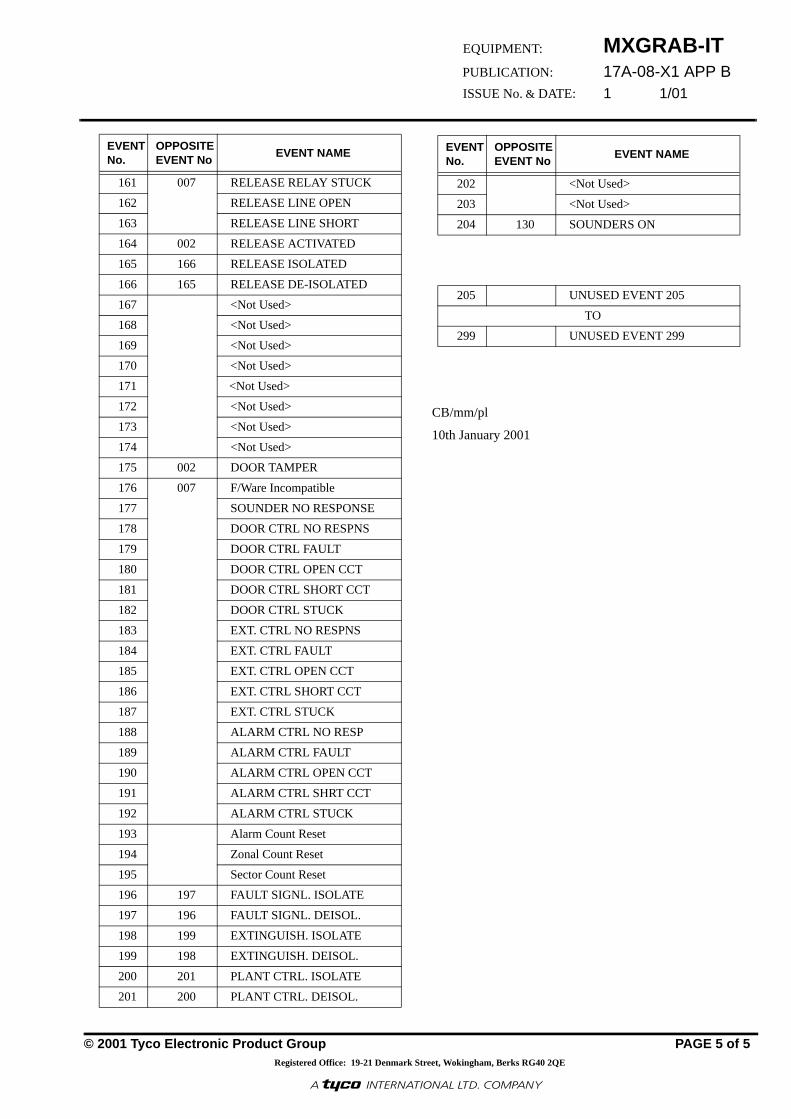
MXGRAB-IT17A-08-X1 APP B1 1/01
© 2001 Tyco Electronic Product Group PAGE 5 of 5
Registered Office: 19-21 Denmark Street, Wokingham, Berks RG40 2QE
EQUIPMENT:
PUBLICATION:
ISSUE No. & DATE:
«¥����¥³¸¾¯¼¸«¾³¹¸«¶¥¶¾®�¥¹·º«¸Ã
161 007 RELEASE RELAY STUCK
162 RELEASE LINE OPEN
163 RELEASE LINE SHORT
164 002 RELEASE ACTIVATED
165 166 RELEASE ISOLATED
166 165 RELEASE DE-ISOLATED
167 <Not Used>
168 <Not Used>
169 <Not Used>
170 <Not Used>
171 <Not Used>
172 <Not Used>
173 <Not Used>
174 <Not Used>
175 002 DOOR TAMPER
176 007 F/Ware Incompatible
177 SOUNDER NO RESPONSE
178 DOOR CTRL NO RESPNS
179 DOOR CTRL FAULT
180 DOOR CTRL OPEN CCT
181 DOOR CTRL SHORT CCT
182 DOOR CTRL STUCK
183 EXT. CTRL NO RESPNS
184 EXT. CTRL FAULT
185 EXT. CTRL OPEN CCT
186 EXT. CTRL SHORT CCT
187 EXT. CTRL STUCK
188 ALARM CTRL NO RESP
189 ALARM CTRL FAULT
190 ALARM CTRL OPEN CCT
191 ALARM CTRL SHRT CCT
192 ALARM CTRL STUCK
193 Alarm Count Reset
194 Zonal Count Reset
195 Sector Count Reset
196 197 FAULT SIGNL. ISOLATE
197 196 FAULT SIGNL. DEISOL.
198 199 EXTINGUISH. ISOLATE
199 198 EXTINGUISH. DEISOL.
200 201 PLANT CTRL. ISOLATE
201 200 PLANT CTRL. DEISOL.
EVENT No.
OPPOSITEEVENT No
EVENT NAME
CB/mm/pl
10th January 2001
202 <Not Used>
203 <Not Used>
204 130 SOUNDERS ON
205 UNUSED EVENT 205
TO
299 UNUSED EVENT 299
EVENT No.
OPPOSITEEVENT No
EVENT NAME

MXGRAB-IT17A-08-X1 APP C
1 1/01
© 2001 Tyco Electronic Product Group PAGE 1 of 1Registered Office: 19-21 Denmark Street, Wokingham, Berks RG40 2QE
EQUIPMENT:
PUBLICATION:
ISSUE No. & DATE:
«¥����¥³¸¾¯¼¸«¾³¹¸«¶¥¶¾®�¥¹·º«¸Ã
APPENDIX CMAP DETAILS SYNTAX
Blocks in the .DXF files can have attributes. Each attribute has a tag-name - this is just a name for attributes of a type. InAutoCad in the ‘Edit Attributes’ dialog for a block, the prompt strings are seen for the different attributes. Each tag-name hasa prompt string. The Syntax Fields in ‘Map Details’ allow the user to:
• Identify which tag-name in the .DXF blocks hold information on ‘Point Address’, ‘Panel Number’, ‘GOTOinformation’ and ‘View Identification’.
• Describe the format of strings used for these attributes in this .DXF file. This allows the strings in the .DXF tobe decoded.
(See Publication 17A-08-X1 ‘MXGraph CAD Operator Guide’ to see how the prompt strings are set up foreach of the attributes on different kinds of blocks).
Making the tag-name and string part modifiable, allows MXGRAB-IT to be compatible with blocks that are not in a standardformat. This means that the minimum of work has to be done changing DXF files.
EXAMPLE - Typical values on MAP table records
Field Commonly holds “tag-name=string”
Meaning
Panel PANEL=1 Attributes with tag-name PANEL hold a string with ‘’a panel number’’, ““ to use default panel OR ‘’*TG” to use local node.
Point POINT=A1 Attributes with tag-name POINT hold “Point Addresses” in the standard Universal Address format.
View GOTO=NAME Attributes with tag-name GOTO hold a string with the “Main View’’ to go to if this blocks control button is pressed.
Local VIEW=NAME Attributes with tag-name VIEW hold a string with the “Main View” to identify which view the block is on.
Strings can be composed of the following sub-strings, in any order
Field Sub-string How information in the DXF is interpreted
Panel “1”
“*” “any text”
““ - use default panel number “*TG” - use local node“no” - panel numberIgnore any number of characters till the start of the next meaningful sub-stringExactly match but ignore “any text”
Point “A 1”“*” “any text”
An address string in the standard Universal Address format Ignore any number of characters till the start of the next meaningful sub-stringExactly match but ignore “any text”
View NAME“*”“any text”
This string is the “Main View” nameIgnore any number of characters till the start of the next meaningful sub-stringExactly match but ignore “any text”
Local NAME“*”“any text”
This string is the “Main View” nameIgnore any number of characters till the start of the next meaningful sub-stringExactly match but ignore “any text”.
CB/pl 10th January 2001