1999: first two 1,850 mtpd grassroots ammonia plants
TRANSCRIPT
First Two 1,850 MTPD GrassrootsAmmonia Plants
In 1998 two new KAAP grassroots ammonia plants were started up in Point Lisas, Trinidad. Theseplants, Farmland MissChem Ltd. (FMCL) and PCS Nitrogen Train 4 (PCS), represent the first of a
new generation of Kellogg Brown & Root ammonia plants. It is the first time the KBR AdvancedAmmonia Process (KAAP) and KAAP catalyst are used in a grassroots ammonia plant. Not only are
these the first grassroots plants to use KAAP technology, but they are also the largest nameplateammonia plants ever built.
R. B. StraitKellogg Brown & Root, Inc., Houston, TX
Ian WelchPCS Nitrogen Trinidad Ltd, Trinidad, West Indies
introduction
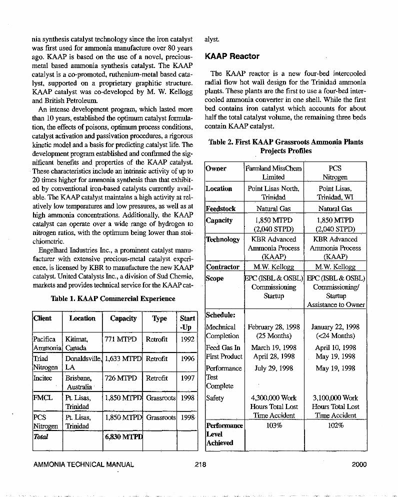
Since 1913, when Haber and Bosch invented the mod-ern ammonia process, more active catalysts have beensought and many improvements have been made in mag-netite (iron) catalysts leading to today's highly activemagnetite catalysts. Scientists have also sought non mag-netite catalysts but without commercial success until BPand Kellogg developed the ruthenium-on-carbon KAAPammonia synthesis catalyst. The first commercial applica-tion of KAAP catalyst was in Pacific Ammonia's plant inKitimat, BC in 1992. This first application was as a retro-fit to increase capacity of an existing plant. In fact, KAAPapplications 2 and 3 were also revamps to increase capac-ity. There is a quantum leap, however, in taking theserevamps and applying that knowledge to the design of thelargest ammonia plant ever built, 1850 mt/d. (See Table
1.)
KAAP Ammonia Process
Table 2 is a summary of the two grassroots KAAPammonia projects in Trinidad.
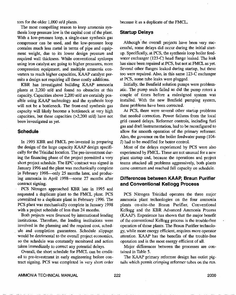
KAAP technology is embodied in the entire KAAPammonia plant flow sheet (see Figure. 1, KBR AdvancedAmmonia Process). The most significant features of thistechnology as applied to FMCL and PCS Nitrogen are:
•KAAP Catalyst• KAAP reactor• Low-pressure synthesis loop• Single case syngas compressor• Combined drive syngas and refrigeration compressors• Combined drive air compressor and electrical genera-
tor.
KAAP Catalyst
The KAAP process is a breakthrough in ammonia syn-thesis technology. Successful commercialization ofKAAP represents the first significant advance in ammo-
AMMONIA TECHNICAL MANUAL 217 2000
nia synthesis catalyst technology since the kon catalystwas first used for ammonia manufacture over 80 yearsago. KAAP is based on the use of a novel, precious-metal based ammonia synthesis catalyst. The KAAPcatalyst is a co-promoted, ruthenium-metal based cata-lyst, supported on a proprietary graphitic structure.KAAP catalyst was co-developed by M. W. Kelloggand British Petroleum.
An intense development program, which lasted morethan 10 years, established the optimum catalyst formula-tion, the effects of poisons, optimum process conditions,catalyst activation and passivation procedures, a rigorouskinetic model and a basis for predicting catalyst life. Thedevelopment program established and confirmed the sig-nificant benefits and properties of the KAAP catalyst.These characteristics include an intrinsic activity of up to20 times higher for ammonia synthesis than that exhibit-ed by conventional iron-based catalysts currently avail-able. The KAAP catalyst maintains a high activity at rel-atively low temperatures and low pressures, as well as athigh ammonia concentrations. Additionally, the KAAPcatalyst can operate over a wide range of hydrogen tonitrogen ratios, with the optimum being lower than stoi-chiometric.
Engelhard Industries Inc., a prominent catalyst manu-facturer with extensive precious-metal catalyst experi-ence, is licensed by KBR to manufacture the new KAAPcatalyst. United Catalysts Inc., a division of Sud Chemie,markets and provides technical service for the KAAP cat-
Table 1. KAAP Commercial Experience
Client
PacificaAmmonia
TriadNitrogen
Incitée
FMCL
PCSNitrogen
Total
Location
Kitimat,Canada
Donaldsville,LA
Brisbane,Australia
Pt. Lisas,Trinidad
PL Lisas,Trinidad
Capacity
771 MTPD
1,633 MTPD
726 MTPD
1,850 MTPD
1,850 MTPD
6,830 MTPE
Type
Retrofit
Retrofit
Retrofit
Grassroots
Grassroots
Start-Up
1992
1996
1997
1998
1998
alyst.
KAAP Reactor
The KAAP reactor is a new four-bed intercooledradial flow hot wall design for the Trinidad ammoniaplants. These plants are the first to use a four-bed inter-cooled ammonia converter in one shell. While the firstbed contains iron catalyst which accounts for abouthalf the total catalyst volume, the remaining three bedscontain KAAP catalyst.
Table 2. First KAAP Grassroots Ammonia PlantsProjects Profiles
Owner
Location
Feedstock
Capacity
Technology
Contractor
Scope
Schedule:
MechnicalCompletion
Feed Gas InFirst Product
PerformanceTestComplete
Safety
PerformanceLevelAchieved
Farmland MissChemLimited
Point Lisas North,Trinidad
Natural Gas
1,850 MTPD(2,040 STPD)
KBR AdvancedAmmonia Process
(KAAP)M. W. Kellogg
EPCaSBL&OSBL)Commissioning
Startup
February 28, 1998(25 Months)
March 19, 1998April 28, 1998
July 29, 1998
4,300,000 WorkHours Total LostTime Accident
103%
PCSNitrogen
Point Lisas,Trinidad, WI
Natural Gas
1,850 MTPD(2,040 STPD)
KBR AdvancedAmmonia Process
(KAAP)
M. W. Kellogg
EPCaSBL&OSBL)Commissioning/
StartupAssistance to Owner
January 22, 1998(<24 Months)
April 10, 1998May 19, 1998
May 19, 1998
3,100,000 WorkHours Total LostTime Accident
102%
AMMONIA TECHNICAL MANUAL 218 2000
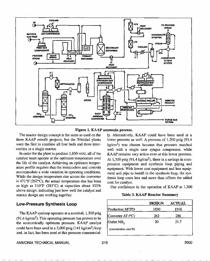
COOUHG
TO PROCESSSTEAM
NATURAL AIR COMPRESSORCAS FEED
co2ABSORBER •D^T- *• PURSE CAS
TO FUEL
Figure 1. KAAPThe reactor design concept is the same as used on the
three KAAP retrofit projects, but the Trinidad plantswere the first to combine all four beds and three inter-coolers in a single reactor.
In order for the plant to produce 1,850 mt/d, all of thecatalyst must operate at the optimum temperature overthe life of the catalyst. Achieving an optimum temper-ature profile requires that the intercoolers and controlsaccommodate a wide variation in operating conditions.While the design temperature rise across the converteris 471°F (262°C), the actual temperature rise has beenas high as 510°F (283°C) at capacities about 103%above design, indicating just how well the catalyst andreactor design are working together.
Low-Pressure Synthesis Loop
The KAAP synloop operates at a nominal, 1,300 psig(91.4 kg/cm2). This operating pressure has proven to bethe economically optimum pressure. KAAP catalystcould have been used in a 2,000 psig (141 kg/cm2) loopand, in fact, has been used at this pressure commercial-
ammonia process.ly. Alternatively, KAAP could have been used at alower pressure as well. A pressure of 1,300 psig (91.4kg/cm2) was chosen because that pressure matchedwell with a single case syngas compressor, whileKAAP remains very active even at this lower pressure.At 1,300 psig (91.4 kg/cm2), there is a savings in com-pression equipment and synthesis loop piping andequipment. With lower cost equipment and less equip-ment and pipe to install in the synthesis loop, the syn-thesis loop costs less and more than offsets the addedcost for catalyst.
Our confidence in the operation of KAAP at 1,300
Table 3. KAAP Reactor Summary
Production MTPD
Converter AT (°C)
Outlet NH3
(concentration, mol-%)
DESIGN
1850
262
20
ACTUAL
1918
286
21.7
AMMONIA TECHNICAL MANUAL 219 2000

psig (91.4 kg/cm2) was justified. For today, the loop issimple to operate and performance is above expecta-tions. (See Table 3.)
Single-Case Synthesis Gas Compressor
For these new Trinidad plants, a single-case synthe-sis gas compressor is used for the first time on a natu-ral gas feedstock KBR ammonia plant. Although KBRhas used a single-case compressor when starting with ahigh-pressure purge gas feed from a source like amethanol plant, KBR had never used a single-casecompressor for a natural gas-fed plant. The reason asingle case synthesis gas compressor can be used is thatthe synthesis loop pressure is so low at only 1,300 psig(91.4 kg/cm2).
One clear benefit of a single case synthesis gas com-pressor is the lower cost of this normally very expen-sive equipment item. And since there is now 'only onecase to operate and maintain, the plant should be morereliable and less costly to maintain.
Conbined-Drive Syngas and RefrigerationCompressors
KAAP technology includes the combined drive forboth the single-case syngas and two-case refrigerationcompressors. Trinidad was the first place Kellogg com-bined these two services in a single train. However,Brown & Root had used a combined drive for both syn-thesis gas and refrigeration compressors in a smallerplant. The driver is a steam turbine taking high-pres-sure steam generated from the process and extractingmedium-pressure steam for the process and other userswhile condensing a small amount of steam as well.This single trahi is simpler, more reliable, less costlyand more efficient than two individual trains.
Each of the individual parts of this combined trainare traditional, but the combination of all the serviceson a single train is unusual for an ammonia plant. Therefrigeration compressor is the traditional two-casemachine, while the steam turbine is the classical high-pressure, extraction condensing turbine and the syngascompressor is similar to just the high-pressure casingof a two-casing syngas compressor.
The design calls for the syngas compressor to controlthe speed of the turbine while the refrigeration system
is controlled by refrigeration temperature level adjust-ments and kickback control on the refrigeration com-pressor during unsteady-state operation. This newdesign has proven to be reliable and easy to operate atall production levels.
Integral Gear Air Compressor
An Integral Gear Compressor (IGC) was used forthe two Trinidad plants. IGC compressors have beenused as air compressors in other applications as wellas in two KBR 1000 mt/d Purifier plants in China.
An IGC consists of one large bullgear and multipledriven shafts with a compressor wheel on each end ofeach driven shaft. In Trinidad each compressor hasthree driven shafts and six compression stages. An IGCwas chosen because the plot space is less than a twocase conventional horizontally split air compressor.The compact IGC design allowed us to connect a gen-erator on the other side of the air compressor without avery long compressor/ generator turbine train.
Electrical Generator
Both new Trinidad plants were built for ammoniaproduction only and no export steam was required ordesired from the ammonia plants. Therefore, no auxil-iary boiler is included inside the ammonia plant,although a package boiler is located in the off-sites,principally for startup steam. Electric power is notalways reliable hi Trinidad, so an electrical generatorwas added inside the ammonia plant. The generatortakes any excess steam generated and converts it toelectricity. The electricity is distributed throughout theammonia plant and off-sites.
Once a reliable source of internally generated powerwas available, more electric motors were used through-out the plant. This resulted in lower cost and more reli-able drivers than the displaced steam turbine drivers.
Combined-Drive Air Compressor andGenerator
As mentioned earlier, an electric power generatorwas included in the design to turn process steam into auseful product, electricity. In other applications thegenerator would have its own medium-pressure con-
AMMONIA TECHNICAL MANUAL 220 2000
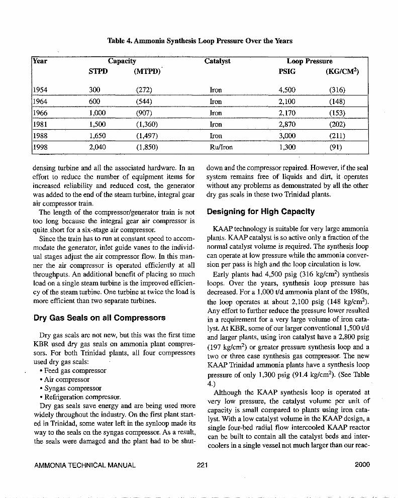
Table 4. Ammonia Synthesis Loop Pressure Over the Years
Year
1954
1964
1966
1981
1988
1998
CapacitySTPD (MTPD)*
300 (272)
600
1,000
1,500
1,650
2,040
(544)
(907)
(1,360)
(1,497)
(1,850)
Catalyst
Iron
Iron
Iron
Iron
Iron
Ru/Iron
Loop PressurePSIG (KG/CM2)
4,500 (316)
2,100
2,170
2,870
3,000
1,300
(148)
(153)
(202)
(211)
(91)
densing turbine and all the associated hardware. In aneffort to reduce the number of equipment items forincreased reliability and reduced cost, the generatorwas added to the end of the steam turbine, integral gearair compressor train.
The length of the compressor/generator train is nottoo long because the integral gear air compressor isquite short for a six-stage air compressor.
Since the train has to run at constant speed to accom-modate the generator, inlet guide vanes to the individ-ual stages adjust the air compressor flow. In this man-ner the air compressor is operated efficiently at allthroughputs. An additional benefit of placing so muchload on a single steam turbine is the improved efficien-cy of the steam turbine. One turbine at twice the load ismore efficient than two separate turbines.
Dry Gas Seals on all Compressors
Dry gas seals are not new, but this was the first timeKBR used dry gas seals on ammonia plant compres-sors. For both Trinidad plants, all four compressorsused dry gas seals:
• Feed gas compressor• Air compressor• Syngas compressor• Refrigeration compressor.Dry gas seals save energy and are being used more
widely throughout the industry. On the first plant start-ed in Trinidad, some water left in the synloop made itsway to the seals on the syngas compressor. As a result,the seals were damaged and the plant had to be shut-
down and the compressor repaired. However, if the sealsystem remains free of liquids and dirt, it operateswithout any problems as demonstrated by all the otherdry gas seals in these two Trinidad plants.
Designing for High Capacity
KAAP technology is suitable for very large ammoniaplants. KAAP catalyst is so active only a fraction of thenormal catalyst volume is required. The synthesis loopcan operate at low pressure while the ammonia conver-sion per pass is high and the loop circulation is low.
Early plants had 4,500 psig (316 kg/cm2) synthesisloops. Over the years, synthesis loop pressure hasdecreased. For a 1,000 t/d ammonia plant of the 1980s,the loop operates at about 2,100 psig (148 kg/cm2).Any effort to further reduce the pressure lower resultedin a requirement for a very large volume of iron cata-lyst. At KBR, some of our larger conventional 1,500 t/dand larger plants, using iron catalyst have a 2,800 psig(197 kg/cm2) or greater pressure synthesis loop and atwo or three case synthesis gas compressor. The newKAAP Trinidad ammonia plants have a synthesis looppressure of only 1,300 psig (91.4 kg/cm2). (See Table4.)
Although the KAAP synthesis loop is operated atvery low pressure, the catalyst volume per unit ofcapacity is small compared to plants using iron cata-lyst. With a low catalyst volume in the KAAP design, asingle four-bed radial flow intercooled KAAP reactorcan be built to contain all the catalyst beds and inter-coolers in a single vessel not much larger than our reac-
AMMONIA TECHNICAL MANUAL 221 2000
tors for the older 1,000 st/d plants.The most compelling reason to keep ammonia syn-
thesis loop pressure low is the capital cost of the plant.With a low-pressure loop, a single-case synthesis gascompressor can be used, and the low-pressure loopcontains much less metal in terms of pipe and equip-ment weight, due to its lower design pressure andrequired wall thickness. While conventional synloopsusing iron catalyst are going to higher pressures, morecompression equipment, and multiple ammonia con-verters to reach higher capacities, KAAP catalyst per-mits a design not requiring all these costly additions.
KBR has investigated building KAAP ammoniaplants at 2,200 st/d and found no obstacles at thiscapacity. Capacities above 2,200 st/d are certainly pos-sible using KAAP technology and the synthesis loopwill not be a bottleneck. The front-end synthesis gascapacity will likely become a bottleneck at very highcapacities, but these capacities (>2,200 st/d) have notbeen investigated as yet.
Schedule
In 1995 KBR and FMCL pre-invested in preparingthe design of the large capacity KAAP design specifi-cally for the Trinidad location. The pre-investment dur-ing the financing phase of the project permitted a veryshort project schedule. The EPC contract was signed inJanuary 1996 and the plant was mechanically completein February 1998—only 25 months later, and produc-ing ammonia in April 1998—some 27 months aftercontract signing.
PCS Nitrogen approached KBR late in 1995 andrequested a duplicate plant to the FMCL plant. PCScommitted to a duplicate plant in February 1996. ThePCS plant was mechanically complete in January 1998with a project schedule of less than 24 months.
Both projects were financed by international lendinginstitutions. Therefore, the lending institutions wereinvolved in the planning and the required cost, sched-ule and completion guarantees. Schedule slippagewould be detrimental to the overall project economics,so the schedule was constantly monitored and actiontaken immediately to correct any potential delays.
Overall, the short schedule for FMCL can be credit-ed to pre-investment in early engineering before con-tract signing. PCS was completed in very short order
because it as a duplicate of the FMCL.
Startup Delays
Although the overall projects have been very suc-cessful, some delays did occur during the initial start-up. Specifically, at PCS, the synthesis loop boiler feed-water exchanger (123-C) head flange leaked. The leakhas since been repaired at PCS, but not at FMCL as yet.Several other flanges leaked during startup, but thesetoo were repaired. Also, in this same 123-C exchangerat PCS, some tube leaks were plugged.
Initially, the Benfield solution pumps were problem-atic. The pump seals failed as did the pump rotors acouple of times before a redesigned system wasinstalled. With the new Benfield pumping system,these problems have been corrected.
At PCS, there were several other startup problemsthat needed correction. Power failures from the localgrid caused delays. Reformer controls, including fuelgas and draft instrumentation, had to be reconfigured toallow for smooth operation of the primary reformer.Also, the governor on the boiler feedwater pump (104-J) had to be modified for better control.
Most of the delays experienced by PCS were alsoexperienced by FMCL. These are not unusual for a newplant startup and, because the operations and projectteams attacked all problems aggressively, both plantscame onstream and reached full capacity on schedule.
Differences between KAAP, Braun Purifierand Conventional Kellogg Process
PCS Nitrogen Trinidad operates the three majorammonia plant technologies on the four ammoniaplants on-site-the Braun Purifier, ConventionalKellogg and the KBR Advanced Ammonia Process(KAAP). Experience has shown that the major benefitof the conventional Kellogg process is the trouble-freeoperation of those plants. The Braun Purifier technolo-gy, while more energy efficient, requires more operatorattention. KAAP has the benefits of the trouble-freeoperation and is the most energy efficient of all.
Major differences between the processes are con-tained in Table 5.
The KAAP primary reformer design has outlet pig-tails which permit crimping reformer tubes on the run.
AMMONIA TECHNICAL MANUAL 222 2000
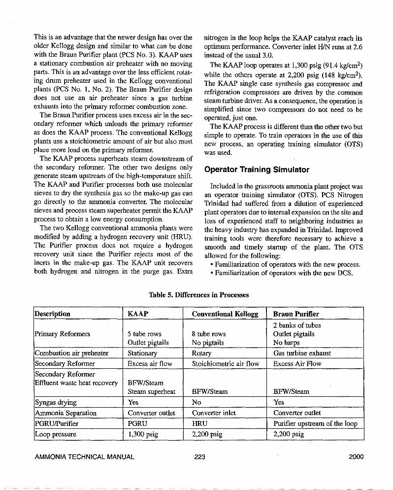
This is an advantage that the newer design has over theolder Kellogg design and similar to what can be donewith the Braun Purifier plant (PCS No. 3). KAAP usesa stationary combustion air preheater with no movingparts. This is an advantage over the less efficient rotat-ing drum preheater used in the Kellogg conventionalplants (PCS No. 1, No. 2). The Braun Purifier designdoes not use an air preheater since a gas turbineexhausts into the primary reformer combustion zone.
The Braun Purifier process uses excess air in the sec-ondary reformer which unloads the primary reformeras does the KAAP process. The conventional Kelloggplants use a stoichiometric amount of air but also mustplace more load on the primary reformer.
The KAAP process superheats steam downstream ofthe secondary reformer. The other two designs onlygenerate steam upstream of the high-temperature shift.The KAAP and Purifier processes both use molecularsieves to dry the synthesis gas so the make-up gas cango directly to the ammonia converter. The molecularsieves and process steam superheater permit the KAAPprocess to obtain a low energy consumption.
The two Kellogg conventional ammonia plants weremodified by adding a hydrogen recovery unit (HRU).The Purifier process does not require a hydrogenrecovery unit since the Purifier rejects most of theinerts in the make-up gas. The KAAP unit recoversboth hydrogen and nitrogen in the purge gas. Extra
nitrogen in the loop helps the KAAP catalyst reach itsoptimum performance. Converter inlet H/N runs at 2.6instead of the usual 3.0.
The KAAP loop operates at 1,300 psig (91.4 kg/cm2)while the others operate at 2,200 psig (148 kg/cm2).The KAAP single case synthesis gas compressor andrefrigeration compressors are driven by the commonsteam turbine driver. As a consequence, the operation issimplified since two compressors do not need to beoperated, just one.
The KAAP process is different than the other two butsimple to operate. To train operators in the use of thisnew process, an operating training simulator (OTS)was used.
Operator Training Simulator
Included in the grassroots ammonia plant project wasan operator training simulator (OTS). PCS NitrogenTrinidad had suffered from a dilution of experiencedplant operators due to internal expansion on the site andloss of experienced staff to neighboring industries asthe heavy industry has expanded in Trinidad. Improvedtraining tools were therefore necessary to achieve asmooth and timely startup of the plant. The OTSallowed for the following:
• Familiarization of operators with the new process.• Familiarization of operators with the new DCS.
Table 5. Differences in Processes
Description
Primary Reformers
Combustion air preheater
Secondary Reformer
Secondary ReformerEffluent waste heat recovery
Syngas drying
Ammonia Separation
PGRU/Purifier
Loop pressure
KAAP
5 tube rowsOutlet pigtails
Stationary
Excess air flow
BFW/SteamSteam superheat
Yes
Converter outlet
PGRU
1,300 psig
Conventional Kellogg
8 tube rowsNo pigtailsRotary
Stoichiometric air flow
BFW/Steam
No
Converter inlet
HRU
2,200 psig
Braun Purifier
2 banks of tubesOutlet pigtailsNo harpsGas turbine exhaust
Excess Air Flow
BFW/Steam
Yes
Converter outlet
Purifier upstream of the loop
2,200 psig
AMMONIA TECHNICAL MANUAL 223 2000

• Preparing operators for emergencies/unusual opera-tions prior to plant startup.
These steps were key to a smooth startup as theprocess technology was a new one for these operatorsand the DCS supplied with the new plant had neverbeen used by the operators before.
The OTS consists of the following:• The simulator/instructor interface-a PC on which a
commercially available simulation software packageruns. A mathematical model of the plant was created onthe software to simulate the process.
• The operator interface-a DCS console exactly likethe one supplied with the plant containing the entiregraphics and control loop configuration. This providedthe same look and feel to the operators.
The OTS was a great success in providing trainingfor the operators, giving them the knowledge and con-fidence to have a safe and trouble-free startup. It is stillused for ongoing training of operators, and an exami-nation on plant operations must be passed on the OTSbefore an operator is certified to operate the actualplant on the DCS.
Performance Capacity
The PCS plant started up quickly and made its firstammonia 39 days after feed gas was introduced to theprimary reformer and reached nameplate capacity 40days later. The plant has been able to consistently pro-duce at a rate of over 2,100 st/d (1,909 mt/d) since thestartup, achieving a monthly performance factor highof over 103%. For a first-of-a-kind ammonia plant, thisis a good result.
The FMCL plant started up quickly and came to 99%of nameplate capacity without much difficulty. At thishigh capacity, just below nameplate capacity, a restric-tion was reached. The restriction to capacity turned outto be an obstruction in the flow path at the inlet to thehigh-pressure steam turbine driving the syngas andrefrigeration compressors. Not knowing exactly wherethe restriction was, all the external potential causeswere investigated first before opening the turbine.The restriction within the turbine internals was thereason for the delay in reaching full capacity. Oncethe turbine was opened and replacement partsinstalled in the area of the restriction, the plant wentimmediately to its nameplate capacity and into its per-
formance test run.Both plants have demonstrated their ability to run in
excess of 1,900 mt/d. (See Table 6.)
Performance Energy
The inside battery limits plants have an energy con-sumption of 25-26 MMBtu (LHV)/st (6.9-7.2Gcal/mt) with no credit for export steam or power. AtPCS, the new KBR KAAP plant has a specific energyabout 15% less than the two conventional KelloggTechnology plants on the site (which include HRU).However, both Trinidad ammonia plants wereplanned to minimize the overall energy consumptionfor the entire complex including the off-sites. The off-sites included but were not limited to:
• Ammonia storage;• Seawater cooling tower;• Package boiler;• Demineralized water plant;• Electrical distribution;• Yard Piping;• Seawater supply outfall; and• Ammonia ship loading facilities.The Trinidad plants bring in only natural gas, raw
water, seawater, and a small amount of electricity dur-ing normal operation; otherwise, the plants are self-sufficient. The only outputs are ammonia and a cou-ple of effluent streams. No steam is imported orexported in normal operation.
Our clients consider specific energy consumptionnumbers confidential, but suffice it to say the overallcomplex energy consumption is about 27-28MMBtu(LHV)/st (7.5-7.8 Gcal/mt). Of course, withthe off-sites varying between plants, the overall com-plex specific energy does also. As compared to con-ventional reduced-energy designs on the same basis,these plants consume about 1.0 MMBtu/st (0.28Gcal/mt) less energy.
Maintenance and Reliability
It is too early to confirm that the maintenance andreliability are better for this design than for more con-ventional ammonia plants. However, from a pureanalysis basis, this design should be better. There arefewer moving parts, and the pressures and temperatures
AMMONIA TECHNICAL MANUAL 224 2000

are less extreme in many areas.The expectation at PCS is that the maintenance will
be easier than for conventional technology. With lessequipment to maintain, such as one less turbine on therefrigeration compressor and one less case on the syn-thesis gas compressor, there should be less mainte-nance required. Electric motor drives are commonlyused instead of steam turbines, and less maintenance isrequired for the motors while all the required power isgenerated within the ammonia plant. The primaryreformer has pinchable outlet pigtails permittingcrimping of reformer tubes on the run.
The energy consumption is less, leading to smallersteam boilers and a smaller cooling water system.Having smaller and fewer items in steam and coolingwater service should lead to less maintenance.
Future
The KAAP Trinidad ammonia plants are the first of anew generation of KBR ammonia plants. Some clientswill choose to duplicate the design, while others willlikely want even larger plants using KAAP technology.KBR has investigated designs using KAAP to 2,200st/d (2,000 mt/d) and found no limit to capacity andlook forward to applying KAAP to even larger capaci-ties to meet our clients' needs.
The KBR Reforming Exchanger System (KRES) isperfectly suited for the front end of a KAAP plant, andwe expect many clients to combine the benefits of bothin future plants.
Since the combining of The M. W. Kellogg Companyand Brown & Root to form Kellogg Brown & Root, wehave combined the best of both processes to form anew process including KRES and KAAP from Kelloggand the Purifier from Brown & Root.
QUESTIONS
(1) What are the control strategies adopted to controlthe syngas compressor suction pressure and the productammonia temperature on the refrigeration machines?
R. B. Strait, Kellogg Brown & Root, Inc.: The syn-gas compressor suction is on pressure control. Thecompressor speed is varied as required to maintain
suction pressure. The refrigeration compressoroperates at the speed of the syn-gas compressor. Thefour-stage refrigeration system varies somewhat intemperature at each of the four boil-off drums toadjust to the ACFM requirement at each speed.
(2) Are both machines driven by the same turbine?Strait: Yes.
AMMONIA TECHNICAL MANUAL 225 2000