1b paper 6: communications - university of cambridge · 1b paper 6: communications handout 4:...
TRANSCRIPT
1B Paper 6: CommunicationsHandout 4: Digital Baseband Modulation
Ramji Venkataramanan
Signal Processing and Communications LabDepartment of [email protected]
Lent Term 2016
1 / 36
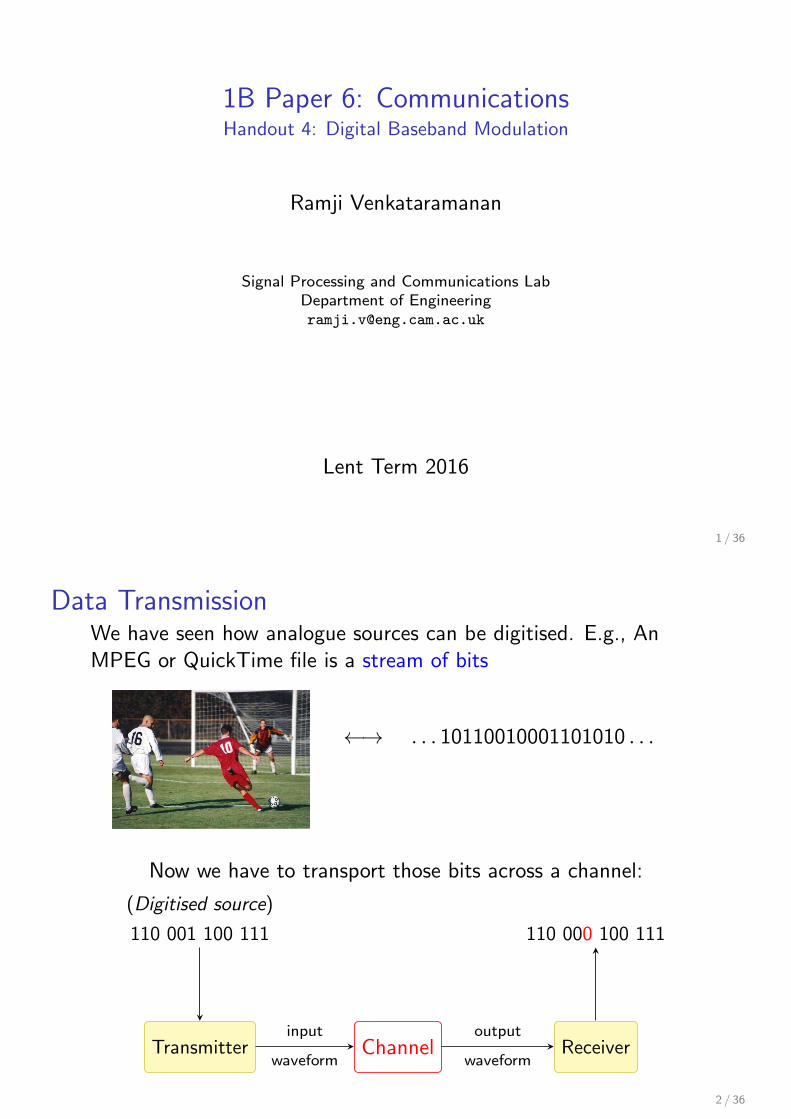
Data TransmissionWe have seen how analogue sources can be digitised. E.g., AnMPEG or QuickTime file is a stream of bits
←→ . . . 10110010001101010 . . .
Now we have to transport those bits across a channel:
(Digitised source)
110 001 100 111
Transmitter Channelwaveform
inputReceiver
waveform
output
110 000 100 111
2 / 36
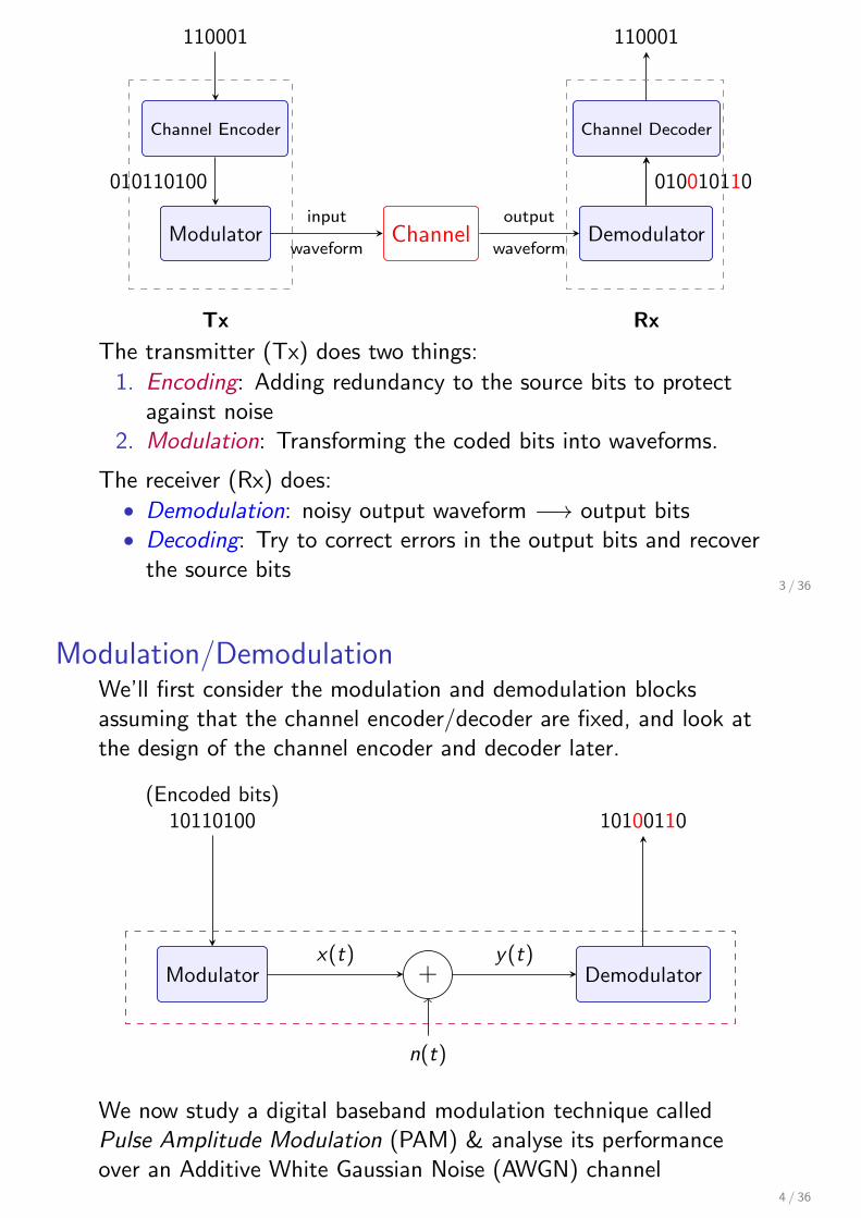
110001
Channel Encoder
Modulator
010110100
Channelwaveform
inputDemodulator
waveform
output
Channel Decoder
010010110
110001
Tx Rx
The transmitter (Tx) does two things:
1. Encoding: Adding redundancy to the source bits to protectagainst noise
2. Modulation: Transforming the coded bits into waveforms.
The receiver (Rx) does:• Demodulation: noisy output waveform −→ output bits• Decoding: Try to correct errors in the output bits and recover
the source bits3 / 36
Modulation/DemodulationWe’ll first consider the modulation and demodulation blocksassuming that the channel encoder/decoder are fixed, and look atthe design of the channel encoder and decoder later.
(Encoded bits)10110100
Modulator +x(t)
Demodulatory(t)
10100110
n(t)
We now study a digital baseband modulation technique calledPulse Amplitude Modulation (PAM) & analyse its performanceover an Additive White Gaussian Noise (AWGN) channel
4 / 36
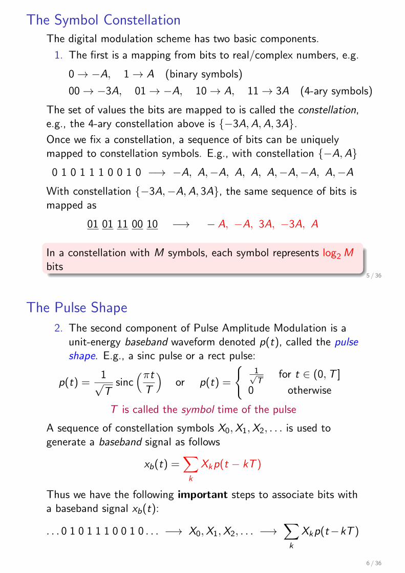
The Symbol ConstellationThe digital modulation scheme has two basic components.
1. The first is a mapping from bits to real/complex numbers, e.g.
0→ −A, 1→ A (binary symbols)
00→ −3A, 01→ −A, 10→ A, 11→ 3A (4-ary symbols)
The set of values the bits are mapped to is called the constellation,e.g., the 4-ary constellation above is {−3A, A, A, 3A}.Once we fix a constellation, a sequence of bits can be uniquelymapped to constellation symbols. E.g., with constellation {−A, A}0 1 0 1 1 1 0 0 1 0 −→ −A, A,−A, A, A, A,−A,−A, A,−A
With constellation {−3A,−A, A, 3A}, the same sequence of bits ismapped as
01 01 11 00 10 −→ − A, −A, 3A, −3A, A
In a constellation with M symbols, each symbol represents log2 Mbits
5 / 36
The Pulse Shape
2. The second component of Pulse Amplitude Modulation is aunit-energy baseband waveform denoted p(t), called the pulseshape. E.g., a sinc pulse or a rect pulse:
p(t) =1√T
sinc(πt
T
)or p(t) =
{1√T
for t ∈ (0, T ]
0 otherwise
T is called the symbol time of the pulse
A sequence of constellation symbols X0, X1, X2, . . . is used togenerate a baseband signal as follows
xb(t) =∑
k
Xkp(t − kT )
Thus we have the following important steps to associate bits witha baseband signal xb(t):
. . . 0 1 0 1 1 1 0 0 1 0 . . . −→ X0, X1, X2, . . . −→∑
k
Xkp(t−kT )
6 / 36
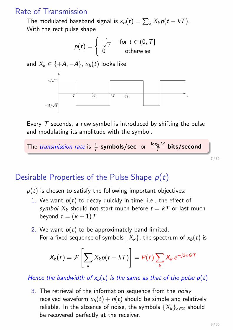
Rate of TransmissionThe modulated baseband signal is xb(t) =
∑k Xkp(t − kT ).
With the rect pulse shape
p(t) =
{1√T
for t ∈ (0, T ]
0 otherwise
and Xk ∈ {+A,−A}, xb(t) looks like
t
A/√T
−A/√T
T 2T 3T 4T
Every T seconds, a new symbol is introduced by shifting the pulseand modulating its amplitude with the symbol.
The transmission rate is 1T symbols/sec or log2 M
T bits/second
7 / 36
Desirable Properties of the Pulse Shape p(t)
p(t) is chosen to satisfy the following important objectives:
1. We want p(t) to decay quickly in time, i.e., the effect ofsymbol Xk should not start much before t = kT or last muchbeyond t = (k + 1)T
2. We want p(t) to be approximately band-limited.For a fixed sequence of symbols {Xk}, the spectrum of xb(t) is
Xb(f ) = F[∑
k
Xkp(t − kT )
]= P(f )
∑
k
Xk e−j2πfkT
Hence the bandwidth of xb(t) is the same as that of the pulse p(t)
3. The retrieval of the information sequence from the noisyreceived waveform xb(t) + n(t) should be simple and relativelyreliable. In the absence of noise, the symbols {Xk}k∈Z shouldbe recovered perfectly at the receiver.
8 / 36
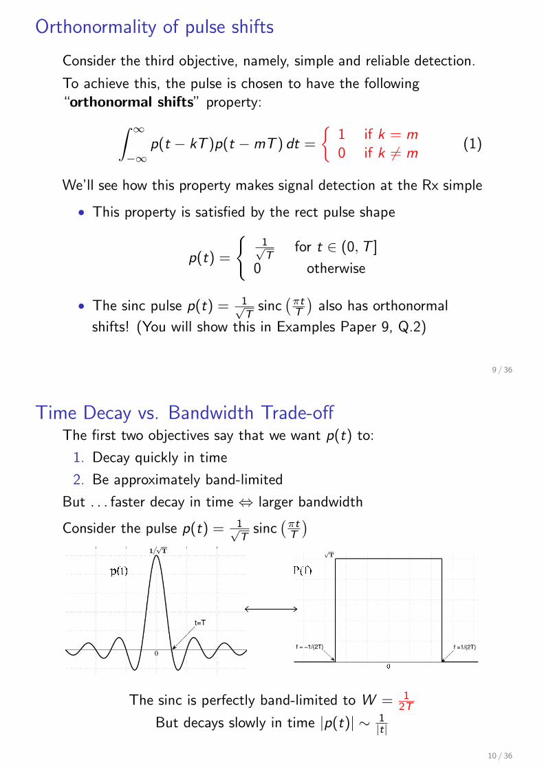
Orthonormality of pulse shifts
Consider the third objective, namely, simple and reliable detection.
To achieve this, the pulse is chosen to have the following“orthonormal shifts” property:
∫ ∞
−∞p(t − kT )p(t −mT ) dt =
{1 if k = m0 if k ̸= m
(1)
We’ll see how this property makes signal detection at the Rx simple
• This property is satisfied by the rect pulse shape
p(t) =
{1√T
for t ∈ (0, T ]
0 otherwise
• The sinc pulse p(t) = 1√T
sinc(
πtT
)also has orthonormal
shifts! (You will show this in Examples Paper 9, Q.2)
9 / 36
Time Decay vs. Bandwidth Trade-offThe first two objectives say that we want p(t) to:
1. Decay quickly in time
2. Be approximately band-limited
But . . . faster decay in time ⇔ larger bandwidth
Consider the pulse p(t) = 1√T
sinc(
πtT
)
p(t)
0
P(f)
The sinc is perfectly band-limited to W = 12T
But decays slowly in time |p(t)| ∼ 1|t|
10 / 36
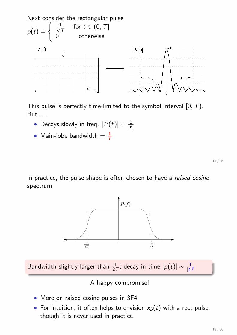
Next consider the rectangular pulse
p(t) =
{1√T
for t ∈ (0, T ]
0 otherwise
1p(t) |P(f)|
This pulse is perfectly time-limited to the symbol interval [0, T ).But . . .
• Decays slowly in freq. |P(f )| ∼ 1|f |
• Main-lobe bandwidth = 1T
11 / 36
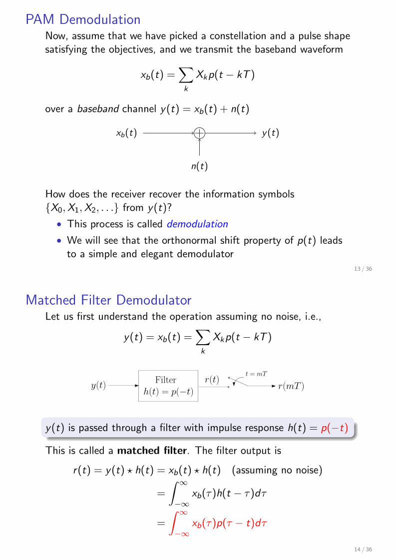
In practice, the pulse shape is often chosen to have a raised cosinespectrum
0 12T
−12T
P (f)
Bandwidth slightly larger than 12T ; decay in time |p(t)| ∼ 1
|t|3
A happy compromise!
• More on raised cosine pulses in 3F4
• For intuition, it often helps to envision xb(t) with a rect pulse,though it is never used in practice
12 / 36
PAM DemodulationNow, assume that we have picked a constellation and a pulse shapesatisfying the objectives, and we transmit the baseband waveform
xb(t) =∑
k
Xkp(t − kT )
over a baseband channel y(t) = xb(t) + n(t)
xb(t) y(t)
n(t)
How does the receiver recover the information symbols{X0,X1, X2, . . .} from y(t)?
• This process is called demodulation
• We will see that the orthonormal shift property of p(t) leadsto a simple and elegant demodulator
13 / 36
Matched Filter DemodulatorLet us first understand the operation assuming no noise, i.e.,
y(t) = xb(t) =∑
k
Xkp(t − kT )
h(t) = p(−t)Filter
y(t)r(t)
t = mT
r(mT )
y(t) is passed through a filter with impulse response h(t) = p(−t)
This is called a matched filter. The filter output is
r(t) = y(t) ⋆ h(t) = xb(t) ⋆ h(t) (assuming no noise)
=
∫ ∞
−∞xb(τ)h(t − τ)dτ
=
∫ ∞
−∞xb(τ)p(τ − t)dτ
14 / 36
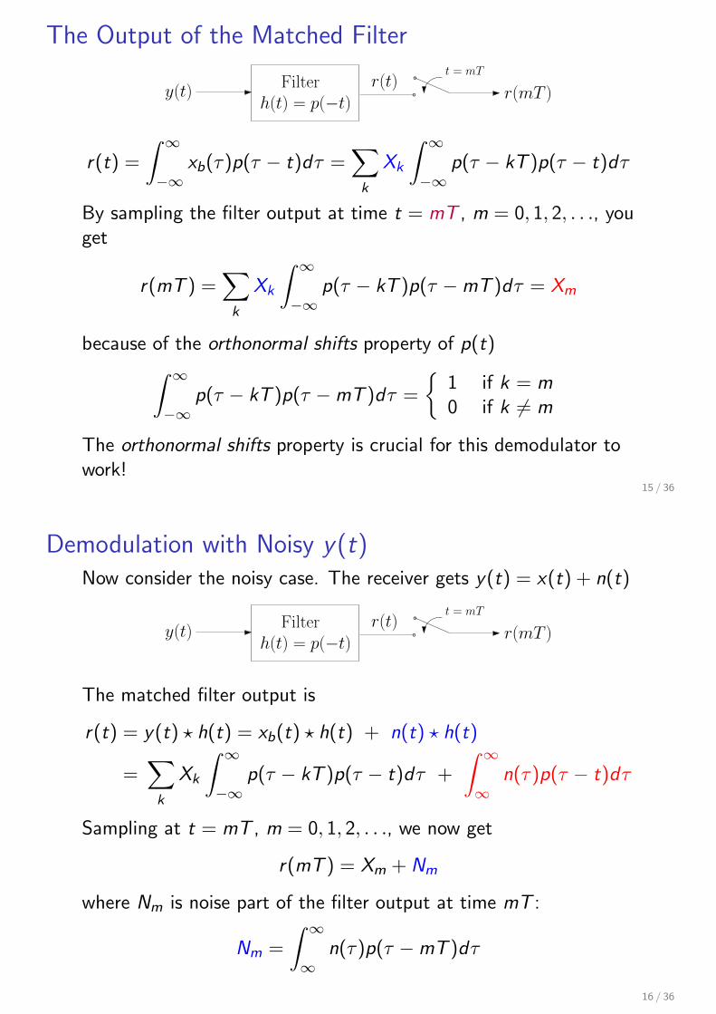
The Output of the Matched Filter
h(t) = p(−t)Filter
y(t)r(t)
t = mT
r(mT )
r(t) =
∫ ∞
−∞xb(τ)p(τ − t)dτ =
∑
k
Xk
∫ ∞
−∞p(τ − kT )p(τ − t)dτ
By sampling the filter output at time t = mT , m = 0, 1, 2, . . ., youget
r(mT ) =∑
k
Xk
∫ ∞
−∞p(τ − kT )p(τ −mT )dτ = Xm
because of the orthonormal shifts property of p(t)∫ ∞
−∞p(τ − kT )p(τ −mT )dτ =
{1 if k = m0 if k ̸= m
The orthonormal shifts property is crucial for this demodulator towork!
15 / 36
Demodulation with Noisy y(t)Now consider the noisy case. The receiver gets y(t) = x(t) + n(t)
h(t) = p(−t)Filter
y(t)r(t)
t = mT
r(mT )
The matched filter output is
r(t) = y(t) ⋆ h(t) = xb(t) ⋆ h(t) + n(t) ⋆ h(t)
=∑
k
Xk
∫ ∞
−∞p(τ − kT )p(τ − t)dτ +
∫ ∞
∞n(τ)p(τ − t)dτ
Sampling at t = mT , m = 0, 1, 2, . . ., we now get
r(mT ) = Xm + Nm
where Nm is noise part of the filter output at time mT :
Nm =
∫ ∞
∞n(τ)p(τ −mT )dτ
16 / 36
Properties of the NoiseLet us denote r(mT ), the sampled output at time mT , by Ym.
Ym = Xm + Nm, m = 0, 1, 2, . . .
Note that this is a discrete-time channel. We have converted thecontinuous-time problem into a discrete-time one of detecting thesymbols Xm from the noisy outputs Ym.
• To do this, we first need to understand the properties of thenoise Nm. Recall that
Nm =
∫ ∞
∞n(τ)p(τ −mT )dτ
• Nm is a random variable whose distribution depends on thestatistics of the random process n(t).
You will learn about random processes and their characterisation in 3F1
& 3F4, but this is outside the scope of this course. For now, we will
directly specify the distribution of Nm and analyse the detection problem.17 / 36
Ym = Xm + Nm, m = 0, 1, 2, . . .
Modelling n(t) as a Gaussian process leads to the followingimportant characterisation of Nm:
• For each m, Nm is a Gaussian random variable with zeromean, and variance σ2 that can be estimated empirically
• Further N1,N2, . . . are independent
• Thus the sequence of random variables {Nm}, m = 0, 1, . . .are independent and identically distributed as N (0, σ2).
Detection• At the Rx, how do we detect the information symbol Xm from
Ym for m = 0, 1, . . .?
• Remember that each Xm belongs to the symbol constellation
18 / 36
Detection for Binary PAMLet’s start with a simple binary constellation, then generalise.
Consider a constellation where each Xm ∈ {−A, A}. This is calledbinary PAM or BPSK (‘Binary Phase Shift Keying’)
Y = X + N
The detection problem is now:Given Y , how to decide whether X = A or X = −A?
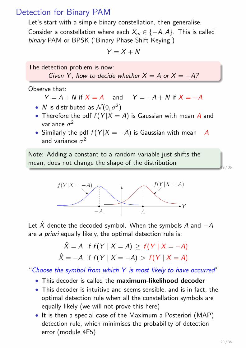
Observe that:Y = A + N if X = A and Y = −A + N if X = −A
• N is distributed as N (0, σ2)• Therefore the pdf f (Y |X = A) is Gaussian with mean A and
variance σ2
• Similarly the pdf f (Y |X = −A) is Gaussian with mean −Aand variance σ2
Note: Adding a constant to a random variable just shifts themean, does not change the shape of the distribution
19 / 36
−A A
f (Y |X = −A) f (Y |X = A)
Y
Let X̂ denote the decoded symbol. When the symbols A and −Aare a priori equally likely, the optimal detection rule is:
X̂ = A if f (Y | X = A) ≥ f (Y | X = −A)
X̂ = −A if f (Y | X = −A) > f (Y | X = A)
“Choose the symbol from which Y is most likely to have occurred”
• This decoder is called the maximum-likelihood decoder• This decoder is intuitive and seems sensible, and is in fact, the
optimal detection rule when all the constellation symbols areequally likely (we will not prove this here)
• It is then a special case of the Maximum a Posteriori (MAP)detection rule, which minimises the probability of detectionerror (module 4F5)
20 / 36
−A A
f (Y |X = −A) f (Y |X = A)
Y
The detection rule can be compactly written as
X̂ = arg maxx∈{A,−A}
f (Y |X = x)
X̂ = arg maxx∈{A,−A}
f (Y |X = x)
= arg maxx∈{A,−A}
1√2πσ2
e−(Y −x)2/2σ2= arg min
x∈{A,−A}(Y − x)2
Thus the detection rule is just: X̂ = A if Y ≥ 0, X̂ = −A if Y < 0“Choose the constellation symbol closest to the output Y ”
21 / 36
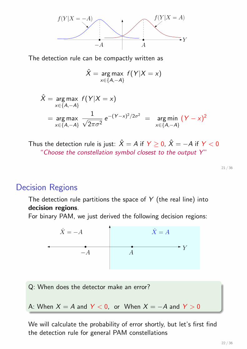
Decision Regions
The detection rule partitions the space of Y (the real line) intodecision regions.For binary PAM, we just derived the following decision regions:
−A A
X̂ = AX̂ = −A
Y
Q: When does the detector make an error?
A: When X = A and Y < 0, or When X = −A and Y > 0
We will calculate the probability of error shortly, but let’s first findthe detection rule for general PAM constellations
22 / 36
Detection for General PAM Constellations
The detection rule can easily be extended to a generalconstellation C• E.g., C may be the 3-ary constellation {−2A, 0, 2A} or a 4-ary
constellation {−3A,−A, A, 3A}• The maximum-likelihood principle is the same: “Choose the
constellation symbol from which y is most likely to haveoccurred ”
X̂ = arg maxx∈ C
f (Y |X = x)
= arg maxx∈ C
1√2πσ2
e−(Y −x)2/2σ2= arg min
x∈ C(Y − x)2
Thus, the detection rule for any PAM constellation boils down to:“Choose the constellation symbol closest to the output Y ”
23 / 36
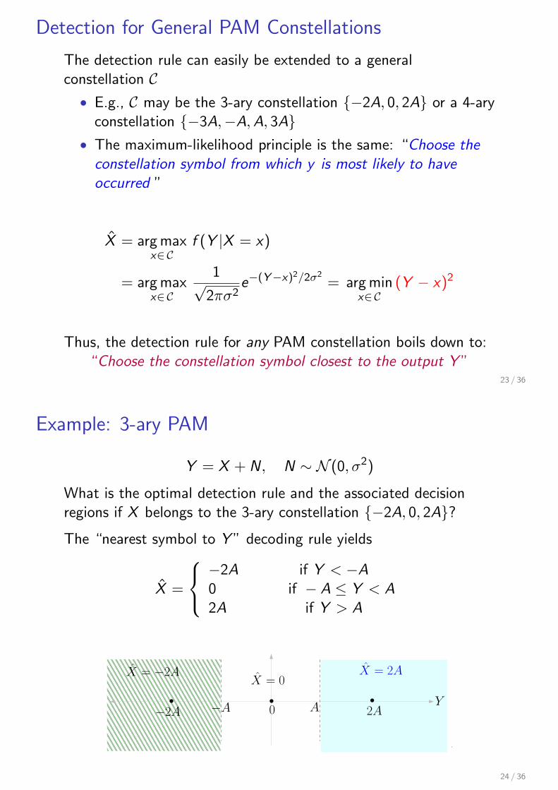
Example: 3-ary PAM
Y = X + N, N ∼ N (0, σ2)
What is the optimal detection rule and the associated decisionregions if X belongs to the 3-ary constellation {−2A, 0, 2A}?The “nearest symbol to Y ” decoding rule yields
X̂ =
−2A if Y < −A0 if − A ≤ Y < A2A if Y > A
−2A 2A
X̂ = 2AX̂ = −2A
−A A
X̂ = 0
Y0
24 / 36
Probability of Detection Error
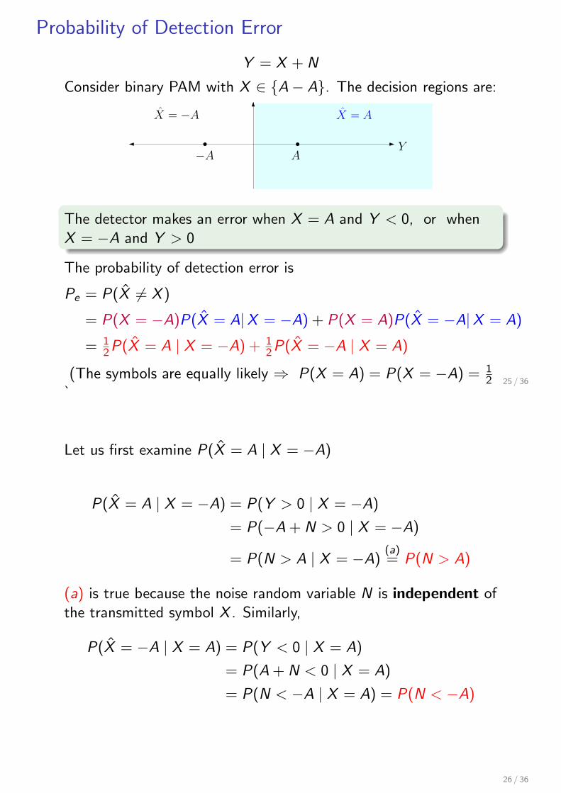
Y = X + N
Consider binary PAM with X ∈ {A− A}. The decision regions are:
−A A
X̂ = AX̂ = −A
Y
The detector makes an error when X = A and Y < 0, or whenX = −A and Y > 0
The probability of detection error is
Pe = P(X̂ ̸= X )
= P(X = −A)P(X̂ = A|X = −A) + P(X = A)P(X̂ = −A|X = A)
= 12P(X̂ = A | X = −A) + 1
2P(X̂ = −A | X = A)
(The symbols are equally likely ⇒ P(X = A) = P(X = −A) = 12
)25 / 36
Let us first examine P(X̂ = A | X = −A)
P(X̂ = A | X = −A) = P(Y > 0 | X = −A)
= P(−A + N > 0 | X = −A)
= P(N > A | X = −A)(a)= P(N > A)
(a) is true because the noise random variable N is independent ofthe transmitted symbol X . Similarly,
P(X̂ = −A | X = A) = P(Y < 0 | X = A)
= P(A + N < 0 | X = A)
= P(N < −A | X = A) = P(N < −A)
26 / 36
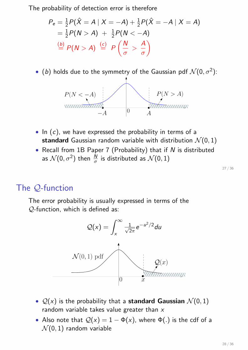
The probability of detection error is therefore
Pe = 12P(X̂ = A | X = −A) + 1
2P(X̂ = −A | X = A)
= 12P(N > A) + 1
2P(N < −A)
(b)= P(N > A)
(c)= P
(N
σ>
A
σ
)
• (b) holds due to the symmetry of the Gaussian pdf N (0, σ2):
−A A0
P (N > A)P (N < −A)
• In (c), we have expressed the probability in terms of astandard Gaussian random variable with distribution N (0, 1)
• Recall from 1B Paper 7 (Probability) that if N is distributedas N (0, σ2) then N
σ is distributed as N (0, 1)
27 / 36
The Q-function
The error probability is usually expressed in terms of theQ-function, which is defined as:
Q(x) =
∫ ∞
x
1√2π
e−u2/2du
x0
Q(x)N (0, 1) pdf
• Q(x) is the probability that a standard Gaussian N (0, 1)random variable takes value greater than x
• Also note that Q(x) = 1− Φ(x), where Φ(.) is the cdf of aN (0, 1) random variable
28 / 36
Pe in terms of the signal-to-noise ratioThe probability of detection error is therefore
Pe = P(N > A) = P
(N
σ>
A
σ
)= Q
(A
σ
)= Q
(√Es
σ2
)
where Es is the average energy per symbol of the constellation:
Es =1
2(A2 + (−A)2) = A2
• For a binary constellation, each symbol corresponds to 1 bit.⇒ the average energy per bit Eb is also equal to A2 in thiscase
• For an M-point constellation, the average energy per symbolEs = Eb log2 M
• Ebσ2 is called the signal-to-noise ratio (snr) of the transmissionscheme
• Pe can be plotted as a function of the snr Ebσ2 . . .
29 / 36
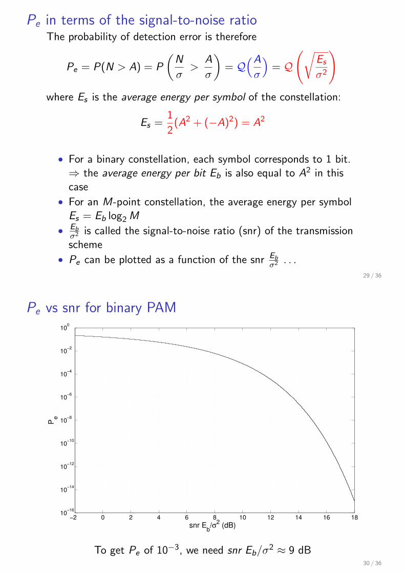
Pe vs snr for binary PAM
−2 0 2 4 6 8 10 12 14 16 1810
−16
10−14
10−12
10−10
10−8
10−6
10−4
10−2
100
snr Eb/σ
2 (dB)
Pe
To get Pe of 10−3, we need snr Eb/σ2 ≈ 9 dB30 / 36
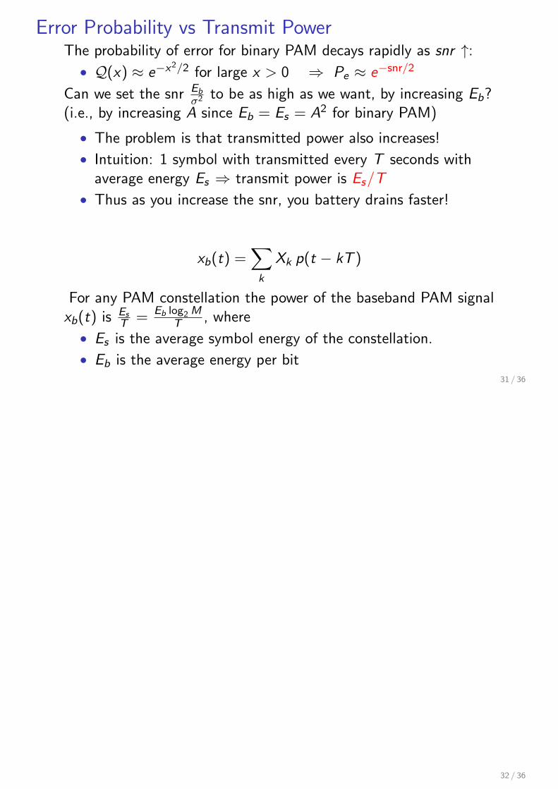
Error Probability vs Transmit PowerThe probability of error for binary PAM decays rapidly as snr ↑:• Q(x) ≈ e−x2/2 for large x > 0 ⇒ Pe ≈ e−snr/2
Can we set the snr Ebσ2 to be as high as we want, by increasing Eb?
(i.e., by increasing A since Eb = Es = A2 for binary PAM)
• The problem is that transmitted power also increases!
• Intuition: 1 symbol with transmitted every T seconds withaverage energy Es ⇒ transmit power is Es/T
• Thus as you increase the snr, you battery drains faster!
xb(t) =∑
k
Xk p(t − kT )
For any PAM constellation the power of the baseband PAM signalxb(t) is Es
T = Eb log2 MT , where
• Es is the average symbol energy of the constellation.
• Eb is the average energy per bit31 / 36
32 / 36
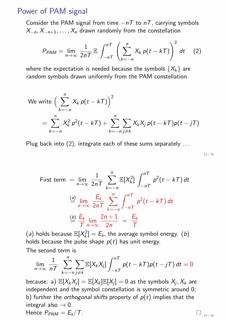
Power of PAM signal
Consider the PAM signal from time −nT to nT , carrying symbolsX−n, X−n+1, . . . , Xn drawn randomly from the constellation
PPAM = limn→∞
1
2nTE∫ nT
−nT
(n∑
k=−n
Xk p(t − kT )
)2
dt (2)
where the expectation is needed because the symbols {Xk} arerandom symbols drawn uniformly from the PAM constellation.
We write( n∑
k=−n
Xk p(t − kT ))2
=n∑
k=−n
X 2k p2(t − kT ) +
n∑
k=−n
∑
j ̸=k
XkXj p(t − kT )p(t − jT )
Plug back into (2), integrate each of these sums separately . . .
33 / 36
First term = limn→∞
1
2nT
n∑
k=−n
E[X 2k ]
∫ nT
−nTp2(t − kT ) dt
(a)= lim
n→∞Es
2nT
n∑
k=−n
∫ nT
−nTp2(t − kT ) dt
(b)=
Es
Tlim
n→∞2n + 1
2n=
Es
T
(a) holds because E[X 2k ] = Es , the average symbol energy. (b)
holds because the pulse shape p(t) has unit energy.
The second term is
limn→∞
1
nT
n∑
k=−n
∑
j ̸=k
E[XkXj ]
∫ nT
−nTp(t − kT )p(t − jT ) dt = 0
because: a) E[XkXj ] = E[Xk ]E[Xj ] = 0 as the symbols Xj , Xk areindependent and the symbol constellation is symmetric around 0;b) further the orthogonal shifts property of p(t) implies that theintegral also → 0.Hence PPAM = Es/T .
34 / 36

Pulse Amplitude Modulation - The Key Points
10110100
Modulator +xb(t)
Demodulatory(t)
10100100
n(t)
PAM is a way to map a sequence of information bits to acontinuous-time baseband waveform
1. Pick a constellation, map the information bits to symbolsX1, X2, . . . in the constellation
2. These symbols then modulate the amplitude of a pulse shapep(t) to generate the baseband waveform xb(t)
xb(t) =∑
k
Xkp(t − kT )
35 / 36
Desirable properties of the pulse shape p(t):
• p(t) should decay quickly in time; its bandwidth W shouldn’tbe too large
• Orthonormal shifts property for simple and reliable decoding
At the receiver, first demodulate then detect:
• The demodulator is a matched filter with IR h(t) = p(−t)
• Matched filter output is sampled at times . . . , 0, T , 2T , . . ..At time mT , the output is
Ym = Xm + Nm
Nm is Gaussian noise with zero mean and variance σ2 thatcan be empirically estimated
• Detection rule: X̂m = the constellation symbol closest to Ym
Probability of detection error can be calculated:
• Decays exponentially with snr Es/σ2
• Es is average energy/symbol of the constellation; power ofPAM waveform xb(t) is Es/T
36 / 36