2 . 0 p r o j e c t d e s c r i p t i o n 2.pdf · also located underground are two refuge...
TRANSCRIPT

Tantalum Mining Corporation 10 1301660300-REP-V0001-00 Project Description
2 . 0 P R O J E C T D E S C R I P T I O N
The following chapter provides an overview of the current operation of the TANCO
facility. No changes are proposed to the current operation, with the exception of the
relocation of TANCO’s final discharge point from Bernic Lake to Bernic Creek.
2 . 1 M I N E R A L & S U R F A C E R I G H T S
TANCO currently holds 13 surface leases (Figure 2.1):
M-126 to M-130, inclusive (dated April 2, 1968);
M-145 to M-149, inclusive (dated April 7, 1971);
SL-1 (dated September 8, 1992);
SL-3 (dated October 16, 1995); and,
SL-11 (dated July 23, 2008, and held by Coltan Mines Ltd., a subsidiary of
TANCO).
TANCO currently holds 3 mineral leases (Figure 2.2):
ML-04 to ML-06, inclusive (dated April 1, 1992).
The proposed location of the temporary access road (portion of), temporary dike and
dewatering/effluent pipelines west of the mine to Bernic Creek are located on Crown
land.
2 . 2 G E O L O G I C A L R E S O U R C E S & M I N E L I F E
The mine has been developed in what is referred to as the “TANCO Pegmatite” deposit,
which is situated in the Archaen Bird River Greenstone Belt (comprised of metavolcanic
and related and derived metasedimentary rocks of the Rice Lake Group). The
pegmatite is estimated to be approximately 2.6 billion years old and is approximately
1,400 m in length, 100 m in thickness, and varies from 300 to 820 m in width.
TANCO estimates that the remaining mine life, based on mine reserves and production
rates, is five to ten years. TANCO is currently evaluating options to extend mine life
through alternate mining scenarios/methods.

Tantalum Mining Corporation 11 1301660300-REP-V0001-00 Project Description
2 . 3 C U R R E N T O P E R A T I O N S
2.3.1 EXISTIN G SURF ACE FACIL IT IES & INFRASTRU CTU RE
Infrastructure on the TANCO Project Site (i.e., the facility footprint) covers
approximately 85 hectares. Surface infrastructure required to support mining includes
(Figure 2.3):
headframe and portal;
tantalum/spodumene mill and dry grinding plant;
warehouse/maintenance shop;
mine dry;
Cesium products facility (chemical plant);
Cesium containment cells and residue stockpile;
tailings management areas;
switchgear/transformer station;
storage facilities;
quarries;
access road;
parking lot;
office facilities; and,
security building.
2.3.2 M IN IN G
The pegmatite is essentially a horizontal rock formation. Pollucite, spodumene, and
tantalum are all located in separate zones of the formation. Mining activities historically
often had to be planned to coordinate mining of one ore to obtain access to another
product. Generally, the three product areas are now discrete so that mining of one
product does not usually affect mining of the other products. TANCO is currently only
mining pollucite.
2.3.3 M IN IN G MET HOD AND PR ODUCT ION RAT ES
Mining is by the room and pillar method. At full production, the capacity of the mine is
approximately 1,000 t/day. The capacity of the mine and mill will not be affected by the
proposed undertaking. At present, TANCO is mining and milling pollucite only at a rate
of 100 t/day.

FIGURE 2.1SURFACE LEASES

LITH 8 MB9324 LITH 9 MB9325
LITH 6 MB9322 LITH 3 MB9319 LITH 1 MB9317LITH 7 MB9323
LITH 12 MB9450
YITT 8 W51828
LITH 10 MB9326
LITH 4 MB9320
YITT 11 MB1592YITT 10 W51830
BRP 19 MB5155
MUM 2 MB5689SOAP 3 W54749MUM MB5596MUM 1 MB5688MUM 3 MB5690
YITT 4 W50913
CLOVER MB3376
LITH 13 MB9449
LITH 2 MB9318
LITH 11 MB9447
LITH 5 MB9321
BRP 14 MB608BRP 20 MB5156
YITT 9 W51829
BRP 1 MB634
BERNIC 1 MB2051
THAW W46815
YITT 5 W51488
BRP 15 MB609
SPRING W46816
BRP 21 MB5157
ML 4
ML 5
ML 6
ML 331
1001660200-SKT-V0015-A
FIGURE 2.2MINERAL LEASES
People, Passion, Performance. Trusted Globally.A TETRA TECH COMPANY
BernicLake
Tanco Mine
BirseLake
BernicCreek
0 1 20.5Kilometers
X:\T-Z\Tantalum Mining Corporation - 0166\10016602.00 - Facility Relicensing Strategy\CAD\Env\FRS report figures\1001660200-SKT-V0015-A.mxd
TANCO Mine Road
Mining Claim
Tantalum Mining Corporation of Canada Ltd.Mining Lease
LEGEND
TANCO Mine
Roadway
Water Body
Water Course
Topographic Contour (50')
N

West Discharge
POLISHINGPOND
CPF ContainmentCell No. 1CPF Containment
Cell No. 2
WESTTAILINGS
MANAGEMENT AREA
WestDam
Dam No. 4
Cell 2Recharge
PondBERNIC LAKE
MAIN DAMTANCO
Mine Road(MD-1)
Quarry
Waste RockStorage Area
ExplosivesStorage
East DamEAST
TAILINGS MANAGEMENT
AREA
WasteTransferStation North Dam
Manitoba Hydro78KV
Former EastDischarge
D
FIGURE 2.3GENERAL SITE PLAN OF THE TANCO
MINE AT BERNIC LAKE, MANITOBA
0 100 300200
Metres
N
N

Tantalum Mining Corporation 15 1301660300-REP-V0001-00 Project Description
2.3.4 M IN E OPENIN GS AND VENTILATION
There are four mine openings: the main ramp, the shaft, and two vent raises
(Figure 2.4). The vent raises are located 15 m east of the mill (Main Vent Fan) and
approximately 450 m southeast of the mill (East Fan).
2.3.5 UND ER GR OUND INFR AST RUCTUR E
Blasted ore is mucked using load, haul, dump equipment (scooptrams) and/or 26 metric
tonne ore trucks to move the ore to one of several ore passes. Rock breakers are used
to break the rock to less than 7.5 cm and the rock is sent down the ore pass to the
second level. A rail system, located on the second level, allows a locomotive to haul up
to five full ore cars to the loading pocket where the ore is loaded into one of two 3 ton
skips which are hoisted to surface via the shaft. At surface the skips are dumped into
one of two coarse ore bins.
Also located underground are two refuge stations, one secured powder magazine, and
one secured detonator magazine. An underground communication system was
installed in 2009 providing telephone and WIFI access to most locations underground.
The use of the emergency broadcast feature of the phones is used to notify of an
emergency event. The emergency response plan is included in Appendix B.
2.3.6 M IN E WATER MAN AGEMENT
Water from the mine workings is routed to the underground sump. The actual routing
varies based on the source of the water and flow rates: i.e., if minewater is at a higher
level than the sump, the water can be directed with trenches or drilling, but if minewater
is at a lower level than the sump, pumps are used to pump the water up to a level
where it can drain into the main sump. Minewater is pumped from the sump to surface
using an 8 stage horizontal ring section pump with a capacity of 1.25 m3/minute.
Minewater is then directed to the West TMA via one of the tailings lines. Net water
production from the underground is approximately 116,000 m3 per year, with about 85%
of this quantity derived from mine seepage and the balance being fresh water from
Bernic Lake which is used for drilling and washing. The water is pumped intermittently;
water flows underground can change based on rainfall or mining activities (e.g., access
to a new fracture zone, sealing up a new fracture zone with grout). The main
dewatering pump has a backup emergency power source in the event of a power
failure, and there is a backup pump available in the event of a main pump failure.

M A N I T O B A
FIGURE 2.4IDEALIZED MINE CROSS-SECTION
LOOKING SOUTH WEST

Tantalum Mining Corporation 17 1301660300-REP-V0001-00 Project Description
2.3.7 M IN IN G WAST E
As required, up to 200 tonnes of waste rock per year are transported to the surface,
mainly for immediate use on the mine road. The waste rock used to maintain the mine
road has traditionally been feldspar, although more recently amphibolite has been used.
The waste rock is non-acid generating, as shown by acid-base accounting (ABA) test
results in the Mine Closure Plan.
2.3.8 M ILL IN G & TAIL INGS MANAGEMENT
Pollucite is crushed and ground to minus 200 mesh in the dry grinding plant, then
directed to the Cesium Products Facility (CPF) for production of cesium chemical
products.
Tantalum and spodumene concentrates have historically been produced by gravity and
flotation processes, respectively. During these processes, the ore is crushed and
ground to minus 12 mm size, then concentrated using gravity separation methods
(heavy media, hydrosizers, tables, and spirals), followed with flotation to produce
finalconcentrates. The tantalum and spodumene tailings were then directed to the West
Tailings Management Area (Figure 2.3).
The facility has two tailings management areas (TMA), East TMA and the West TMA
(Figure 2.3). The general composition of the tailings is a combination of tantalum and
spodumene gangue consisting of various feldspars, quartz, amphiboles, gabbro,
unrecovered tantalum and lithium minerals, and other minor pegmatite minerals.
2.3.9 WAT ER USE & MANAGEMENT
The TANCO operation draws water from two sources: fresh water from Bernic Lake and
recycled water from the West TMA polishing pond. All withdrawals from Bernic Lake are
subject to the conditions of Water Rights Act Licence No. 92-125 which sets the
maximum withdrawal rate at 0.113 m3/sec and the maximum annual withdrawal at
3,700,500 m3(3,700.5 cubic decametres).
The conventional milling process uses all of the recycled water and approximately 55%
of the Bernic Lake water. Approximately 40% of the Bernic Lake water goes to the CPF
for cooling and, with the exception of evaporative losses, is returned to the polishing
pond. Small quantities of fresh water are directed to the mine for drilling and washdown
(<1%), to the CPF process (2%), and for domestic uses (2%) in the office, mill,
warehouse, and mine dry. Water for domestic use is passed through a sand bed filter
and is chlorinated prior to distribution for domestic uses other than drinking.
The combined total annual water discharge from the mine and mill to the West TMA is
2,400,000 m3 (maximum); this is less than water volume drawn into the mill because
some water is evaporated off during drying of final product for both tantalum and
spodumene.

Tantalum Mining Corporation 18 1301660300-REP-V0001-00 Project Description
The annual discharge from the west discharge (compliance point) of the polishing pond
is approximately 3,000,000 m3 when the mine is in full production. During 2010 and
2011, when tantalum processing was temporarily suspended, annual discharge was
recorded at 1,671,435 m3 and 1,118,757 m
3, respectively. As TANCO has recently
announced that tantalum mining and processing has again been suspended, flows are
expected to return to these levels during 2013 and onward.
2.3.10 WAST E MAN AGEMENT
Solid waste produced at the facility is collected at the waste transfer station where it is
held until it is transported to a licenced facility. Sanitary waste produced at the facility is
directed to a licensed tile field. All hazardous materials, waste petroleum products, and
special wastes are collected for proper offsite disposal at a licensed facility.
A small (<5,000 tonnes) waste rock stockpile is located north of the parking lot
(Figure 2.3). Waste rock (e.g., amphibolite, quartz, feldspar, granite) is generally
managed underground; a small stockpile of non-acid generating waste rock is
maintained on surface for use in various tasks (e.g., tailings dam construction, road
maintenance).
2.3.11 S ITE RUN OFF MAN AGEMENT
The majority of the minesite runoff drains into either the West TMA or East TMA. The
West TMA drains through a polishing pond to the lake via an engineered control
structure, which is referred to as the West Discharge. This constitutes the only mine
effluent discharge to Bernic Lake. Until June 2004, surface runoff and tailings
porewater from the East TMA drained to Bernic Lake via the East Discharge; a culvert
installed in the main dam of the east TMA. The East Discharge was discontinued in
June 2004 when the culvert was removed and all runoff accumulation was directed to
the West TMA.
Surface runoff and tailings porewater from the East TMA drains to the phreatic ditch,
which flows under CPF Containment Cell No.2 to the Surge Pond, and is then pumped
to the West TMA via the tailings lines.
Direct runoff to Bernic Lake from the minesite is limited to the southern margins of the
site, outside of the perimeter minesite road. All site roads have been contoured to
direct runoff to the Surge Pond, the polishing pond, the East TMA, or the West TMA.
Cooling water from the CPF is discharged into the polishing pond approximately 50 m
east of the West Discharge. Boiler blowdown water from the CPF is added to this
stream and is diluted by the cooling water flow. The annual discharge of boiler
blowdown water is 136.5 cubic metres. Water used for cooling in the CPF has no
contact with any products or reagents.

Tantalum Mining Corporation 19 1301660300-REP-V0001-00 Project Description
2.3.12 D ISCH AR GES T O WATER
At present, discharge from the mine to Bernic Lake is via a weir and culvert located at
the dyke between the West TMA polishing pond and Bernic Lake. The discharge point
is known as the West Discharge and reports to Bernic Lake (Figure 2.3). Monitoring of
West Discharge quality has been conducted since the discharge was first established in
1996. The water quality monitoring required under Environment Act License No. 973 is
limited to monthly measurements of pH and total suspended solids (TSS). More
detailed characterization of the West Discharge was voluntarily initiated in1997 by
TANCO in anticipation of the requirement to comply with the Metal Mining Effluent
Regulations, which ultimately came into effect in December 2002. The MMER requires
weekly monitoring of pH and TSS and routine monitoring of what are termed deleterious
substances (total As, Cu, Pb, Ni, Zn, and Ra226
) and acute toxicity to rainbow trout
(48 hr LC50) and Daphnia magna (96 hr LC50).
Management of pH in the polishing pond is necessary to counter the effects of
photosynthetically elevated pH that occurs as a result of algal photosynthesis during the
open water season; therefore, an acid addition system was developed and implemented
at the West Discharge in 2011. One measurement of pH outside of the prescribed
MMER range was recorded in 2012. In consultation with Environment Canada, TANCO
took the following measures to address pH concerns and maintain compliance by:
1. Relocating the acid addition point to the mill and establishing electronic monitoring
of pH values with a verification check by operations staff before discharge to the
TMA polishing pond;
2. Pneumatic mixing of the acid tote to the mixing procedure to ensure proper dilution
of the acid; and
3. Addition of an aeration system to mitigate the effects of algal activity in the settling
and polishing ponds.
Since implementing the aeration system and monitoring its effects on effluent quality, it
has not been necessary to make use of the acid addition system; however it is available
if necessary.
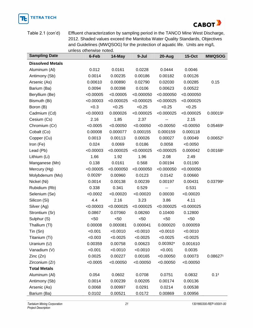
Effluent characterization data for 2012 are detailed in Table 2.1. The discharge
characterization data were compared to current Manitoba Water Quality Standards
Objectives and Guidelines (MWQSOG; MB Water Stewardship 2011) for the protection
of aquatic life to identify potential impacts. Total phosphorus exceeded the Tier III
MWQSOG of 0.025 mg/L for all of the sampling periods. Total Iron exceeded the
Tier III MWQSOG value of 0.300 mg/L in October. No exceedances of the MMER
discharge limits occurred on the characterization sampling events.

Tantalum Mining Corporation 20 1301660300-REP-V0001-00 Project Description
Table 2. 1 Effluent characterization by sampling period in the TANCO Mine West Discharge, 2012. Shaded values exceed the Manitoba Water Quality Standards, Objectives and Guidelines (MWQSOG) for the protection of aquatic life. Units are mg/L unless otherwise noted.
Sampling Date 6-Feb 14-May 9-Jul 20-Aug 15-Oct MWQSOG
Physicochemical
pH (pH units) 7.80 7.56 7.70 8.70 7.40 6.5 - 9.0
Hydroxide (OH-) <0.50 <0.50 <0.50 <0.50 <0.50
Specific Conductance (µS/cm@25°C) 214 253 250 292 335
Total Dissolved Solids 150 154 176 184 204 Hardness, dissolved 61.2 58.3 58.8 77.0 89.6 Hardness, total 61.0 61.1 61.9 80.2 88.7
Alkalinity (PP as CaCO3) <0.50 <0.50 -- 1 <1
Alkalinity (Total as CaCO3) 64.0 46.2 70 60 50
Bicarbonate (HCO3) 78.1 56.4 86.0 70.0 60.0
Carbonate (CO3) <0.50 <0.50 <0.5 1.2 <0.5 Total Suspended Solids 3.7 10.5 9.9 21.5 16.9 Turbidity (NTU) 3.25 7.25 7.6 22.0 8.7 True Colour (Col. Units) 20 20 16 13 11 Major Ions
Potassium, dissolved (K+) 4.3 4.49 4.46 5.30 5.50 Sodium, dissolved (Na
+) 14.9 17.6 17.4 19.9 19.5
Calcium, dissolved (Ca2+
) 18.8 18.8 19.0 25.9 30.2 Magnesium, dissolved (Mg
2+) 3.5 2.80 2.76 2.98 3.45
Chloride, dissolved (Cl-) 8.8 11.0 10.0 11.0 10.0
Fluoride, dissolved (F-) 0.31 0.39 0.54 0.81 0.71
Sulphate, dissolved (SO4-) 20.5 51.1 33.1 59.9 90.8
Nutrients
Organic Carbon, dissolved 9.98 9.38 11.60 9.64 9.57 Organic Carbon, total 12.70 11.30 11.10 9.82 10.40 Nitrite -- -- 0.0069 0.0078 0.0104 0.06
Nitrate 1.740 0.819 0.0337 <0.0020 0.3220 13
Nitrate_Nitrite 1.740 0.843 0.0406 0.0028 0.3320 Ammonia 0.3700 0.0520 0.3500 <0.0050 0.2600 Total Kjeldahl Nitrogen 1.04 1.090 1.840 2.230 1.490 Total Nitrogen 2.78 1.940 1.880 2.230 1.830 Phosphorus, total dissolved 0.034 0.0185 0.1740 0.0792 0.0149 Phosphorus, total 0.068 0.104 0.283 0.272 0.1420 0.025
Biological
Chlorophyll a (µg/L) -- 26.9 11.9 81.4 24.8 Radiochemical
Radium-226 (Bq/L) 0.006 <0.005 <0.005 <0.005 <0.005
Tantalum Mining Corporation 21 1301660300-REP-V0001-00 Project Description
Table 2.1 (con’d) Effluent characterization by sampling period in the TANCO Mine West Discharge,
2012. Shaded values exceed the Manitoba Water Quality Standards, Objectives
and Guidelines (MWQSOG) for the protection of aquatic life. Units are mg/L
unless otherwise noted. Sampling Date 6-Feb 14-May 9-Jul 20-Aug 15-Oct MWQSOG
Dissolved Metals
Aluminum (Al) 0.012 0.0161 0.0228 0.0444 0.0046 Antimony (Sb) 0.0014 0.00235 0.00186 0.00182 0.00126
Arsenic (As) 0.00610 0.00890 0.02790 0.02030 0.00285 0.15
Barium (Ba) 0.0094 0.00398 0.0106 0.00623 0.00522
Beryllium (Be) <0.00005 <0.00005 <0.000050 <0.000050 <0.000050
Bismuth (Bi) <0.00003 <0.000025 <0.000025 <0.000025 <0.000025
Boron (B) <0.3 <0.25 <0.25 <0.25 <0.25
Cadmium (Cd) <0.00003 0.000026 <0.000025 <0.000025 <0.000025 0.00019¹
Cesium (Cs) 2.16 1.85 2.37 -- 2.15 Chromium (Cr) <0.0005 <0.00050 <0.00050 <0.00050 <0.00050 0.05469¹
Cobalt (Co) 0.00008 0.000077 0.000155 0.000159 0.000118 Copper (Cu) 0.0013 0.00113 0.00026 0.00027 0.00049 0.00652¹
Iron (Fe) 0.024 0.0069 0.0186 0.0058 <0.0050 Lead (Pb) <0.00003 <0.000025 <0.000025 <0.000025 0.000042 0.00168¹
Lithium (Li) 1.66 1.92 1.96 2.08 2.49 Manganese (Mn) 0.138 0.0161 0.568 0.00194 0.01190
Mercury (Hg) <0.00005 <0.000050 <0.000050 <0.000050 <0.000050
Molybdenum (Mo) 0.0026ᵃ 0.00960 0.0123 0.0142 0.00660 Nickel (Ni) 0.0014 0.00138 0.00239 0.00197 0.00431 0.03799¹
Rubidium (Rb) 0.338 0.341 0.529 -- 0.531 Selenium (Se) <0.0002 <0.00020 <0.00020 0.00030 <0.00020 Silicon (Si) 4.4 2.16 3.23 3.86 4.11 Silver (Ag) <0.00003 <0.000025 <0.000025 <0.000025 <0.000025 Strontium (Sr) 0.0867 0.07060 0.08260 0.10400 0.12800 Sulphur (S) <50 <50 <50 <50 <50 Thallium (Tl) 0.00008 0.000081 0.000041 0.000020 0.000059 Tin (Sn) <0.001 <0.0010 <0.0010 <0.0010 <0.0010 Titanium (Ti) <0.003 <0.0025 <0.0025 <0.0025 <0.0025 Uranium (U) 0.00359 0.00758 0.00623 0.00392ᵃ 0.001610 Vanadium (V) <0.001 <0.0010 <0.0010 <0.001 0.0035 Zinc (Zn) 0.0025 0.00227 0.00165 <0.00050 0.00073 0.08627¹
Zirconium (Zr) <0.0005 <0.00050 <0.00050 <0.00050 <0.00050 Total Metals
Aluminum (Al) 0.054 0.0602 0.0708 0.0751 0.0832 0.1²
Antimony (Sb) 0.0014 0.00239 0.00205 0.00174 0.00136 Arsenic (As) 0.0068 0.00997 0.0291 0.0214 0.00538 Barium (Ba) 0.0102 0.00521 0.0172 0.00869 0.00956

Tantalum Mining Corporation 22 1301660300-REP-V0001-00 Project Description
Table 2.1 (con’d) Effluent characterization by sampling period in the TANCO Mine West Discharge,
2012. Shaded values exceed the Manitoba Water Quality Standards, Objectives
and Guidelines (MWQSOG) for the protection of aquatic life. Units are mg/L
unless otherwise noted. Sampling Date 6-Feb 14-May 9-Jul 20-Aug 15-Oct MWQSOG
Beryllium (Be) <0.00005 <0.00005 0.000064 0.000063 0.000111 Bismuth (Bi) <0.00003 0.000041 0.000049 0.000036 <0.000025 Boron (B) <0.3 <0.25 <0.25 <0.25 <0.25 1.5
Cadmium (Cd) <0.00003 <0.000025 <0.000025 <0.000025 <0.000025 Calcium (Ca) 19.2 19.7 20.2 27.0 30.1
Cesium (Cs) 1.93 1.92 2.56 2.48 2.20
Chromium (Cr) <0.0005 <0.00050 <0.00050 <0.00050 <0.00050
Cobalt (Co) 0.00009 0.000078 0.000196 0.000161 0.000286
Copper (Cu) 0.0015 0.00116 0.00121 0.00130 0.00097
Iron (Fe) 0.172 0.120 0.243 0.207 0.375 0.3
Lead (Pb) 0.00024 0.000232 0.000634 0.000233 0.000502
Lithium (Li) 1.54 1.88 2.02 2.11 2.49
Magnesium (Mg) 3.2 2.86 2.78 3.09 3.29
Manganese (Mn) 0.204 0.125 1.09 0.372 0.620
Mercury (Hg) <0.00005 <0.000050 <0.00005 <0.000050 <0.000050 0.00026
Molybdenum (Mo) 0.0020 0.0100 0.0127 0.0123 0.00609 0.073
Nickel (Ni) 0.0013 0.00205 0.00299 0.00301 0.005
Potassium (K) 3.8 4.71 4.62 5.57 5.42
Rubidium (Rb) 0.309 0.356 0.576 0.53 0.558
Selenium (Se) <0.0002 <0.00020 <0.00020 0.00023 <0.00020 0.0010
Silicon (Si) 4.9 2.33 3.42 4.13 4.46
Silver (Ag) <0.00003 <0.000025 <0.000025 <0.000025 <0.000025 0.0001
Sodium (Na) 13.7 17.4 17.8 20.2 18.3
Strontium (Sr) 0.0812 0.0743 0.0868 0.0990 0.12700
Sulphur (S) <50 <50 <50 <50 <50
Thallium (Tl) 0.00010 0.000093 0.000051 0.000028 0.000085 0.0008
Tin (Sn) <0.0010 <0.0010 <0.0010 <0.0010 <0.0010
Titanium (Ti) <0.003 <0.0025 <0.0025 <0.0025 <0.0025
Uranium (U) 0.00309 0.00762 0.00649 0.00314 0.00155 0.015
Vanadium (V) <0.001 <0.0010 <0.0010 0.0035 <0.0010
Zinc (Zn) 0.0031 0.00629 0.00663 0.00259 0.00481
Zirconium (Zr) <0.00050 <0.00050 <0.00050 <0.00050 <0.00050
¹Calculated based on average dissolved hardness (69.0 mg/L) and average duration 4 days.
²Guideline based on pH ≥ 6.5.

Tantalum Mining Corporation 23 1301660300-REP-V0001-00 Project Description
Surface water samples are collected from the west basin of Bernic Lake four times per
year. Samples are analysed and compared to current Manitoba Water Quality
Standards Objectives and Guidelines (MWQSOG; MB Water Stewardship 2011) for the
protection of aquatic life to identify potential impacts. The results of this sampling are
included in Section 5.
2.3.13 EMISSIONS MAN AGEMEN T
2.3.13.1 A I R
The facility produces the following emissions to air which are estimated and reported
annually to the National Pollutant Release Inventory:
Formic acid;
Sulphuric acid;
Particulate matter (PM10 and PM2.5); and
Dust (from roads).
Formic acid vapour is emitted during truck unloading into the formic acid bulk storage
tank. Sulphuric acid mist and vapour are emitted from the digester in the chemical plant
where the pollucite ore is dissolved.
TANCO operates 11 baghouses and dust collectors in place to control emissions of fine
host mineral particles. Air dispersion modeling was completed in 2013 using the
US Environmental Protection Agency’s SCREEN3 air dispersion model (Tetra Tech
2013).The cumulative ground level concentrations of particulate matter calculated over
a 24 hour averaging period were compared against the maximum 24 hour allowable
limit determined by the Manitoba Ambient Air Quality Criteria. It was found that
particulate matter generated by the mine (57.5 µg/m3) at peak operation is significantly
lower than the Manitoba Ambient Air Quality Criteria Maximum Acceptable Level
Concentration (120 µg/m3) at a distance of 100 m from the release location.
2.3.13.2 GREE NHO USE GAS EMI SSI ONS
Approximately 87% of recent project-related greenhouse gas (GHG) emissions originate
from the combustion of propane for process steam production in the chemical plant,
process and space heating for most on-site buildings, and heating the underground
mine workings during the winter months. Heating of the ventilation air that goes
underground during the winter months occurs at the vent fans. A further 10% of GHG
emissions originate from the combustion of fuels in mobile equipment operation on
surface and underground.

Tantalum Mining Corporation 24 1301660300-REP-V0001-00 Project Description
2.3.14 S ITE SECU RIT Y
Site security is maintained at the main entrance to the minesite by a contracted security
service (Figure 2.3). All contractors and visitors must sign in at the security building
before entering or leaving the site.
2.3.15 CONTIN GENC Y AND EMERGENC Y RESPONSE PLAN
TANCO maintains a standard of emergency preparedness to provide timely and
coordinated response to an emergency, in order to minimize the effects of the
emergency or disaster on TANCO employees, the public, the mine site and the
environment. In the case of an emergency underground, the TANCO Mine Department
will follow response procedures in compliance with Standard Mine Rescue Practice. In
response to the recent fall of ground, TANCO installed highly sensitive micro-seismic
monitoring equipment in the mine and revised the Emergency Response Plan to include
a mine flood evacuation plan. A copy of the Emergency Response Plan is included in
Appendix B.
TANCO has established an agreement with the RM of Alexander to provide fire/rescue
emergency services to the mine of required. The agreement includes provisions to
ensure that alternative resources would be available for the RM should they be
responding to a call at the mine during a subsequent emergency.
2 . 4 P R O P O S E D A C T I V I T I E S
2.4.1 QUARR YING
Rock to construct the temporary dike will be quarried from an approved, existing quarry
managed by Don Sikora Enterprises. Approximately 13,000 m3 of rock is expected to
be obtained from this quarry for the dike.Rock to be used for the temporary access road
will be obtained from the existing quarry or a new quarry closer to the work site. Rock to
be used for the temporary dike from the existing quarry has been submitted to Maxxam
Analytics for acid-base accounting (ABA) testing with the results available in
4-8 weeks. It is anticipated that, like the waste rock generated from the mine, the rock
obtained from the quarry will be non-acid generating.
2.4.2 TEMPOR AR Y ACC ESS ROAD AND STAGIN G AR EA
A 1,330 m temporary access road and a 0.5 ha staging area will be required to access
the location and facilitate construction of the temporary dike at the Bernic Lake narrows
(Figure 2.5). The temporary road alignment was selected to make use of existing mine
roads and Manitoba Hydro maintenance trails along transmission line so as to minimize
the amount of new road construction. Where possible, the temporary access road has
been aligned within the Manitoba Hydro right-of-way so as to minimize brushing while
maintaining a safe distance from the transmission line. Transmission line crossings
have been minimized and sited adjacent to the towers to provide maximum clearance

Tantalum Mining Corporation 25 1301660300-REP-V0001-00 Project Description
with the conductors. The majority of the temporary road, will be constructed on the
existing mine surface lease while the remaining portion and the temporary staging area
will be constructed on Crown land.
A 585 m section of the existing Manitoba Hydro maintenance trail will be upgraded to a
single-lane road with quarried material (Figure 2.5). Trail curve radiuses at two
locations may need to be adjusted to accommodate the turning radiuses for dam
construction. equipment. Activities will include brushing secondary growth along the
trail, potential minimal timber clearing at adjusted curves, and the placement of quarried
rock (approximately 10,000 m3) in low areas, and surfacing with till. The 745 m of new
road and laydown area will require timber clearing and brushing in pioneered sections
and brushing within the transmission line right-of-way. Timbers and brush will be left in
place and quarried rock will be end-dumped to for a road base. Quarried till will be used
for surfacing.
There are no stream crossings along the alignment. Cross drains will be placed within
lowland area as necessary to maintain surface drainage patterns. Grubbing will be
minimized in order to preserve the root mat and minimize disturbance in the lowland
areas.
A second temporary access road or trail will be constructed from the polishing pond to
the Bernic Creek discharge location to allow pipes associated with water management
of the east basin and mine effluent discharge to be constructed and maintained.
Alignment alternatives for the road/trail are currently being evaluated and every effort
will be made to minimize their impact.
2.4.3 TEMPOR AR Y D IKE
A temporary dike will be constructed at the narrows between the east and west basins
of Bernic Lake (Figure 2.6). The dike location is immediately upstream (east) of the
existing Manitoba Hydro transmission line crossing and placed such that the dike will
not encroach on the transmission line right-of-way. This location was selected because
the dike can be constructed and the west basin dewatered within the shortest possible
time frame in order to minimize environmental risks to the lake and ensure the safety of
mine personnel. The dike will also allow the east basin to be maintained at the normal
water elevation which will preserve the existing fish community and allow at
decommissioning the rapid colonization of the west basin by indigenous fish species
without the need for stocking. The dike will be constructed of locally sourced rock and
grout and/or LLPDE liner.

PROPOSED TEMPORARYACCESS ROAD ALIGNMENT
MINE SITE
BERNIC LAKE
FIGURE 2.5
0 100 300 400200
Metres
N

N
FIGURE 2.6LOCATION, CROSS SECTION
AND PLAN VIEW OFTEMPORARY DIKE
0 40 6020
Metres
-8.0
-7.0
-6.0
-5.0
-4.0
-3.0
-2.0
-1.0
0.0
1.0
2.0
LAKE BOTTOM
NORMAL WATER LEVEL @ 0.0 m (311.56m)
TOP OF DIKE @ 1.84m (313.40m)
HIGH WATER LEVEL @ 0.85m (312.41m)
2:1 SIDE SLOPE
3:1 SIDE SLOPE
NARROWS DAM LOCATION

Tantalum Mining Corporation 28 1301660300-REP-V0001-00 Project Description
Dike construction will begin with a rock fill embankment formed by pushing coarse rock
into Bernic Lake from the north shore. The embankment will require approximately
13,000 m3 of rock fill. A finer transition zone material will then be placed on the
embankment and, if required, an LLDPE liner will be placed on the upstream (east)
face. A key trench along the dike crest will be constructed to secure the liner and then
sand and gravel ballast will be placed on the liner. Rip rap will be placed on the
upstream face in the wave run up zone to provide protection for the ballast and liner. A
passive spillway, running from the crest and down the downstream (west) side of the
dike will be constructed to allow water from severe precipitation events to pass over the
dike without damaging the structure. The spillway will also facilitate the refill of the west
basin prior to the decommissioning of the dike. If dike seepage is observed after the
west basin has been dewatered, a toe drainage collection system may be incorporated
into a toe berm, depending upon seepage volume. The LLPDE liner has a life of five
years. In the unlikely event that the dike is required for more than five years, an
additional liner would be placed on the upstream face of the structure in order to provide
adequate seepage control for the extended service life of the dike. Geotechnical
investigation is underway to determine the depth of the sediment along the alignment of
the narrows dike. If the investigation reveals that the sediment is too weak and
compressible, steel sheet piling may be incorporated into the final design of the dike.
Decommissioning activities will be initiated after two to four years of service and will
begin with the refilling of the west basin. The west basin will be allowed to fill naturally
by discontinuing temporary water management activities and allowing upstream
drainage to discharge through the dike spillway from the east basin. It is anticipated
that natural water elevations will be achieved within 17 months. Once the water levels
on either side of the dam have equalized, the dam crest, rip rap, and liner will be
removed beginning at the south shore. In order to avoid disturbance of the natural
lakebed, some rock, sand, and gravel will be left in the lake. This material will be
contoured with the lake bed and while maintaining a minimum depth of 3 m. The
LLPDE liner will be disposed of at a licensed waste facility while the quarried dam
material will either be stockpiled onshore or recycled for mine use.
2.4.4 TEMPOR AR Y DEWAT ER IN G
Water from the west basin of Bernic Lake will be directed to the natural outflow of Bernic
Lake. Natural wetlands in Bernic Creek have been incorporated in the dewatering
program and will be used throughout the dewatering phase with the purpose of reducing
total suspended solids and nutrients. Dewatering of the Bernic Lake west basin will
begin as soon as hydraulic isolation from the east basin has been achieved at the
temporary dike and continue over a period of 9-12 months. During this period, the
volume of the west basin (9.77M m3) will be removed to Bernic Creek. Surface runoff
into the east and west basin will also be managed during this time.
A containment weir will be constructed across Bernic Creek to prevent the wetlands
from draining back into the west basin as the water level in the west basin declines.
The containment weir will be constructed following the methods outlined for the

Tantalum Mining Corporation 29 1301660300-REP-V0001-00 Project Description
temporary dike. The pipeline will be constructed directly from a barge-mounted
submersible pump anchored over the deepest area of the basin to a diffuser array at the
discharge point in Bernic Creek. The pump suction inlet will be suspended just below
the water surface so as to draw surface water and to avoid causing currents at depth
across the sediments and/or inadvertent lake turn-over and re-suspension of sediments.
The pump will be located above the surface of the water. If a constant pumping rate is
maintained over the nine month dewatering period, the rate would be approximately,
0.75 m3/s.
The assimilation capacity and expected performance criteria for the Bernic Creek
wetland are still under assessment. If the discharge rate exceeds the assimilative
capacity of the wetland then pre-treatment methods will be considered.
2.4.5 TEMPOR AR Y WAT ER MANAGEMENT
The west basin will continue to receive surface water and ground water drainage
through and after dewatering. This water (approximately 4.2M m3/yr) will be allowed to
collect in the dewatered basin. The water will be periodically discharged to the Bernic
Creek wetlands using the equipment and temporary infrastructure constructed to
dewater the basin (Figure 2.7). If phosphorus and/or TSS concentrations become
excessive (i.e., exceed the capacity of the wetland to treat water) then pre-treatment
alternatives will be considered.
The east basin will also continue to receive surface water drainage (approximately
3.2M m3/yr); however, the natural outflow path will be inaccessible. In order to manage
water levels in the east basin a water transfer system will be installed. The system will
consist of a pump in or adjacent to the east basin and pipeline to the Bernic Creek
wetland. The pipeline will roughly follow the temporary access roads. The mine
currently draws 1,000,000 m3/yr of process water from the west basin. A take-off at the
mine site will allow the mine to draw process water from the east basin until the west
basin has been refilled.
The east basin pipeline will be decommissioned and removed at the same time the
temporary dike and access road are decommissioned. Process water will once again
be drawn from the west basin.

0 200 600400
Metres
N
FIGURE 2.7
NARROWS DAM
MINE FEEDWATERPUMP
HYDRO TRANSMISSION
MINE FEEDWATER PIPELINE
PROPOSED ROAD ALIGNMENT
SETTLING AREA
POLISHING POND
MINE EFFLUENT PUMP
DEWATERING PUMP
SILT CURTAIN
BERNIC CREEK
WETLANDS
DEWATERING PIPELINE
EXISTING ROADS
PROPOSEDPIPELINE ALIGNMENT

Tantalum Mining Corporation 31 1301660300-REP-V0001-00 Project Description
2.4.6 EFFLUENT MAN AGEMENT
The existing final discharge point from the polishing pond is at the west basin therefore
a new final discharge point will be required prior to the dewatering of the west basin.
The polishing pond water will be directed to Bernic Creek through a stand-alone pipeline
from the polishing pond (Figure 2.7). A flow meter will be installed to provide flow rates
and volumes. Detailed designed will be provided prior to the change-over during the
2013-2014 winter season. The final discharge point will be maintained for the duration
of the temporary dike at which point the discharge point will be reviewed. TANCO will
continue to work with Environment Canada to develop a long-term solution.
2.4.7 PERMAN ENT D IKE
The temporary dike and dewatering of the west basin will facilitate the construction of a
permanent solution with a much smaller environmental footprint. An extensive
geotechnical investigation of the area is planned for fall 2013. Detailed design including
confirmation of the alignment of the permanent dike will follow subsequent to the
geotechnical investigation and will be provided to the appropriate regulatory agencies
as well as presented to the public.
A permanent dike around the mine workings will reduce the affected area significantly to
less than 50 ha from over 200 ha as per conceptual alignment; Section 3). The
permanent dike will be maintained in place until decommissioning at the end of mine
life. Because the permanent dike will be located within a deeper area of the west basin,
the dike design will need to be more robust than the temporary dike and more detailed
geotechnical investigations will be required before a detailed design can be completed.
2 . 5 D E C O M M I S S I O N I N G A N D R E C L A M A T I O N
At project closure, the minesite will be returned to a state compatible with the
surrounding natural environment. TANCO will follow the plans laid out in the facility's
Closure Plan which was prepared in accordance with Manitoba Mine Closure
Regulation (67/99) and submitted to Mines Branch. TANCO is currently updating the
Closure Plan.