· 2 medical appliances • water feeding • disinfection • laser cooling welding machinery •...
TRANSCRIPT

Small pumpswith magnetic coupling
KleinpumpenMit Magnetkupplung

2
Medical appliances• Waterfeeding• Disinfection• Lasercooling
Welding machinery• Coolingofweldingpistols
Temperature controllers• Processtempering• Processcooling
Railcars• Transformercooling• Drinkingwatersupply• Wastewatersupply• Fuelsupply• Electroniccooling
Aerospace equipment• Fuelsupply• Industrialwatersupply
Industrial and mechanical engineering• Lasercooling• Processcooling• Switchboardcooling• Watertreatment• Boilerfeeding• Washingandcleaning• Servercooling• Extrusiontechnology
Automobile industry• Heatingandairconditioning
systems• Batterycooling• Gearcooling• Fuelsupply
Drink dispensers• Drinkcooling• Bottlefilling• Recirculationofdrinks
Speck Pumpen Solutions for the future
Medizintechnik• Nachspeisung• Desinfektion• Laserkühlung
Schweißmaschinen• Brennerkühlung
Temperiergeräte• Prozesstemperierung• Prozesskühlung
Schienenfahrzeuge• Transformatorenkühlung• Trinkwasserförderung• Grauwasserförderung• Kraftstoffförderung• Elektronikkühlung
Luft- und Raumfahrt• Kraftstoffförderung• Brauchwasserförderung
Industrie- und Apparatebau• Laserkühlung• Prozesskühlung• Schaltschrankkühlung• Wasseraufbereitung• Kesselspeisung• Waschenund
Reinigen• Serverkühlung• Extrusionstechnik
Automobilindustrie• Heiz-undKlimasysteme• Batteriekühlung• Getriebekühlung• Kraftstoffförderung
Getränkeautomaten• Getränkekühlung• Getränkeabfüllung• Getränkeumwälzung
Speck Pumpen Lösungen für die Zukunft
www.speck.de

3Subjecttotechnicalmodificationsanderror.
Small pumpswithmagneticcoupling
Peripheralradpumpen / Regenerative turbine pumpsEC-Gleichstrommotor/BrushlessDCmotor
EC-Gleichstrommotor / Brushless DC motorSeitePageQmax Hmax Qmax Hmax
Type 1/min - rpm V kW l/min m HP USGPM ftY-1638-MM 2000 – 6000 24 0,180 0,5 – 9,0 7 – 57 0.24 0.1 – 2.4 23 – 187 4, 5
Y-2340-SR 1500 – 3800 230 0,075 0,5 – 9,0 5 – 20 0.10 0.1 – 2.4 16 – 65 6, 7
Y-2951-W-MM 2000 – 5000 24 0,180 0,5 – 12,0 18 – 45 0.24 0.1 – 3.2 60 – 148 8, 9
LY-6000-MK 6000 24 0,060 4 32 0.08 1.1 10510, 11
LY-8000-MK 9000 24 0,080 5 38 0.11 1.3 125
Einphasen-undDreiphasenmotoren/Singlephasemotorandthreephasemotor
50 Hz / Cycles | 2800 1/min - rpm 60 Hz / Cycles | 3400 1/min - rpmSeitePageQmax Hmax Qmax Hmax Qmax Hmax Qmax Hmax
Type kW l/min m HP USGPM ft kW l/min m HP USGPM ftY/YS-2951-W-MK 0,12 / 0,25 10-11 28 0.16 / 0.34 2.6-2.9 92 0,12 / 0,25 10-13 28-38 0.16 / 0.34 2.6-3.4 92-125 12, 13
PY-2071-MK 0,25 - 0,55 17 35 0.34 - 0.74 4.5 115 0,25 - 0,55 17 35 0.34 - 0.74 4.5 115 14, 15EY-2251-MK 0,5 37 45 0.67 9.8 148 0,55 37 40 0.74 9.8 131 16, 17EY-4281-MK 1,0 55 57 1.34 14.5 187 1,1 55 50 1.5 14.5 164 18, 19
NPY-2251-MK 0,5 27 48 0.67 7.1 157 0,55 27 48 0.74 7.1 157 20, 21
CY-4281-MK 1,0 - 2,2 28-85 57-78 1.34 - 2.95 7-23 187-256 1,0 - 2,2 85 78 1.34 - 2.95 22.5 256 22, 23
CY-6091-MK 2,8 - 5,5 77-200 83-90 3.8 - 7.5 20-53 272-295 2,8 - 5,5 77-200 83-90 3.8 - 7.5 20-53 272-295 24, 25
Wärmeträgerpumpen - Wasser bis 180 °C / Heat transfer pumps - Water up to 180 °CNPY-2251-MK-HT 0,5 27 48 0.67 7.1 157 0,55 27 48 0.74 7.1 157 26, 27
CY-4281-MK-HT 1,00 - 2,2 28-85 57-78 1.34 - 2.95 7-23 187-256 1,0 - 2,2 28-85 57-78 1.34 - 2.95 7-23 187-256 28, 29
CY-6091-MK-HT 2,8 - 5,5 77-200 83-90 3.8 - 7.5 20-53 272-295 2,8 - 5,5 77-200 83-90 3.8 - 7.5 20-53 272-295 30, 31
Wärmeträgerpumpen - Öl bis 350 °C / Heat transfer pumps - Oil up to 350 °CNPY-2251-MK-TOE 0,5 27 48 0.67 7.1 157 0,55 27 48 0.74 7.1 157 32, 33
CY-4281-MK-TOE 1,0 - 2,2 28-85 57-78 1.34 - 2.95 7-23 187-256 1,0 - 2,2 28-85 57-78 1.34 - 2.95 7-23 187-256 34, 35
CY-6091-MK-TOE 2,8 - 5,5 77-200 83-90 3.8 - 7.5 20-53 272-295 2,8 - 5,5 77-200 83-90 3.8 - 7.5 20-53 272-295 36, 37
Radialradpumpen / Centrifugal pumpsEC-Gleichstrommotor/BrushlessDCmotor
EC-Gleichstrommotor / Brushless DC motorSeitePageQmax Hmax Qmax Hmax
Type 1/min - rpm V kW l/min m HP USGPM ftMY-3-MM 2000 – 6500 24 0,180 5 – 100 1 –14 0.24 1.3 – 26.4 3.3 – 46 38, 39
MY-2-6000-MK 6000 24 0,023 20 9 0.03 5.3 30 40, 41
MY-2-8000-MK 9000 24 0,080 30 15 0.11 7.9 50 42, 43
Drehschieberpumpen / Roller vane pumps50 Hz / Cycles | 2800 1/min - rpm 60 Hz / Cycles | 3400 1/min - rpm
SeitePageQmax Pmax Qmax Pmax Qmax Pmax Qmax Pmax
Type kW l/min bar HP USGPM bar kW l/min psi HP USGPM psiDS-120 / … / 450-MK 0,30 8,3 10,0 0.40 2.2 145 0,30 9,2 10,2 0.40 2.4 148 44, 45
DS-540 / … / 960-MK 0,75 / 0,90 15,6 14,0 1.00 / 1.21 4.1 203 0,75 / 0,90 18,8 14,0 1.00 / 1.21 5.0 203 46, 47
Zahnradpumpen / Gear pumpsEC-Gleichstrommotor/BrushlessDCmotor
EC-Gleichstrommotor / Brushless DC motorSeitePageQmax Pmax Qmax Pmax
Type 1/min - rpm V kW l/min bar HP USGPM psiZY-3-MM 3100 24 0,180 0,5 - 4,5 1 - 8 0.24 0.13 - 1.2 14 - 116 48, 49
Einphasen-undDreiphasenmotoren/Singlephasemotorandthreephasemotor50 Hz / Cycles | 2800 1/min - rpm 60 Hz / Cycles | 3400 1/min - rpm
SeitePageQmax Pmax Qmax Pmax Qmax Pmax Qmax Pmax
Type kW l/h bar HP USGPM psi kW l/h bar HP USGPM psiZY-1 / 2 / 3-MK 0,12 20 – 175 3 – 9 0.16 0.09-0,77 43-130 0,12 25 – 205 3– 9 0.16 0.11-0.90 43-130 50, 51
Inhalt / Contents
TechnischeÄnderungenundIrrtumvorbehalten.
KleinpumpenmitMagnetkupplung
10/2015|1096.1088
4
Y-1638-MM
40 70
8 8
Ø88
151
128
29 84
84
1291
G 1/4G 1/4
22
90
7
106
50
92
Ue*
154 800900411 940515 550.1310.2816
310 412.2
101550914
940
230
412.3 400.1**412.1**
210
400**412**
847
411.1*914.1*
474
096*732*
310.1
900.1
847900411 940
800970154 412.2
101550914
411.1*914.1*
816310 400.1**412.1**
096*732*
400**412**
210
230
Subjecttotechnicalmodificationsanderror.
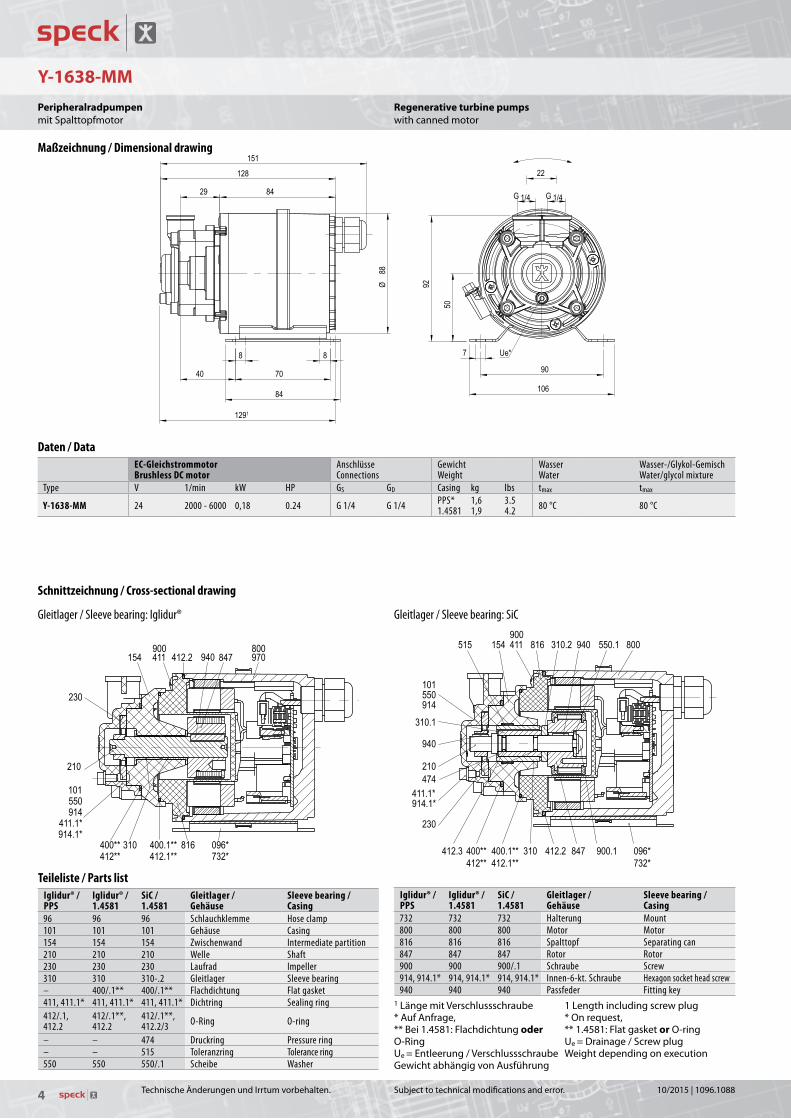
Regenerative turbine pumpswithcannedmotor
Teileliste / Parts listIglidur® / PPS
Iglidur® / 1.4581
SiC / 1.4581
Gleitlager / Gehäuse
Sleeve bearing / Casing
96 96 96 Schlauchklemme Hose clamp101 101 101 Gehäuse Casing154 154 154 Zwischenwand Intermediate partition210 210 210 Welle Shaft230 230 230 Laufrad Impeller310 310 310-.2 Gleitlager Sleeve bearing– 400/.1** 400/.1** Flachdichtung Flat gasket411, 411.1* 411, 411.1* 411, 411.1* Dichtring Sealing ring412/.1, 412.2
412/.1**, 412.2
412/.1**, 412.2/3 O-Ring O-ring
– – 474 Druckring Pressure ring– – 515 Toleranzring Tolerance ring550 550 550/.1 Scheibe Washer
Schnittzeichnung / Cross-sectional drawing
Gleitlager / Sleeve bearing: Iglidur® Gleitlager / Sleeve bearing: SiC
Maßzeichnung / Dimensional drawing
Daten / DataEC-GleichstrommotorBrushless DC motor
AnschlüsseConnections
GewichtWeight
WasserWater
Wasser-/Glykol-GemischWater/glycol mixture
Type V 1/min kW HP GS GD Casing kg lbs tmax tmax
Y-1638-MM 24 2000 - 6000 0,18 0.24 G 1/4 G 1/4 PPS*1.4581
1,61,9
3.54.2 80 °C 80 °C
Iglidur® / PPS
Iglidur® / 1.4581
SiC / 1.4581
Gleitlager / Gehäuse
Sleeve bearing / Casing
732 732 732 Halterung Mount800 800 800 Motor Motor816 816 816 Spalttopf Separating can847 847 847 Rotor Rotor900 900 900/.1 Schraube Screw914, 914.1* 914, 914.1* 914, 914.1* Innen-6-kt. Schraube Hexagon socket head screw940 940 940 Passfeder Fitting key
1LängemitVerschlussschraube*AufAnfrage,**Bei1.4581:FlachdichtungoderO-RingUe=Entleerung/VerschlussschraubeGewichtabhängigvonAusführung
1Lengthincludingscrewplug*Onrequest,**1.4581:FlatgasketorO-ringUe=Drainage/ScrewplugWeightdependingonexecution
TechnischeÄnderungenundIrrtumvorbehalten.
PeripheralradpumpenmitSpalttopfmotor
10/2015|1096.1088

5
Y-1638-MM
Leis
tung
sbed
arf
Puis
sanc
e ab
sorb
ée
Förderstrom / Débit Q [l/min]
Capacity Q [U.S.GPM]
Förd
erhö
he
Hau
teur
man
omét
rique
Tota
l hea
d Po
wer
con
sum
ptio
n
H [m]
P[kW]P1
P[HP]P1
H [feet] 60
50
40
30
20
10
0
0,200
0,175
0,150
0,125
0,100
0,075
0,050
0,025
0 0 1 2 3 4 5 6 7 8 9
0 0.25 0.50 0.75 1.00 1.25 1.50 1.75 2.00 2.25 2.50
0.25
0.20
0.15
0.10
0.05
0
200
175
150
125
100
75
50
25
0
2000 − 6000 1/min - rpm - tr/min
1.4581
PPS
1.4581
PPS
1.4581 = CrNiMo-cast steel
2000–60001/min-rpm
Subjecttotechnicalmodificationsanderror.
H[feet]
Tota
lhea
d
P1[HP]
Pow
erc
onsu
mpt
ion
Capacity Q [U.S.GPM]
Characteristic curvesEveryoperatingpointcanbereachedwithinthesecharacteristiccurvesbysettingdifferentdriveparameters.Thecharacteristiccurvesareappli-cableforthedeliveryofwaterof20°Ctemperatureandanambienttemperatureof20°C.
Thetoleranceoftotalheadandcapacityis±10%,performancetoleranceis+10%.
Ifthepropertyofthepumpedmediadiffers,thecharacteristiccurveschange.
ThepowerconsumptionP1specifiestheelectricalpowerinput.
Regenerative turbine pumpswithcannedmotor
Kennfelder / Characteristic curves
Werkstoffausführungen / Material Design
GehäuseCasing PPS* 1.4581
CrNiMo-cast steel1.4581CrNiMo-cast steel
ZwischenwandIntermediate partition PPS* 1.4581
CrNiMo-cast steel1.4581CrNiMo-cast steel
LaufradImpeller
1.4408*CrNiMo-cast steel*
1.4408, Ni-SiC-beschichtetCrNiMo-cast steel, Ni-SiC coated
1.4408, Ni-SiC-beschichtetCrNiMo-cast steel, Ni-SiC coated
WelleShaft
1.4462*CrNiMo-steel*
1.4462CrNiMo-steel
1.4571CrNiMo-steel
GleitlagerSleeve bearing Iglidur® Iglidur® SiC
SpalttopfSeparating can PPS PPS PPS
*AufAnfrage *Onrequest
TechnischeÄnderungenundIrrtumvorbehalten.
P1[kW]
Leis
tung
sbed
arf
H[m]
Förd
erhö
he
Kennfelder:InnerhalbderdargestelltenKenn-felderistjederBetriebspunktdurchentsprechendeParametrierungdesAntriebesmöglich.
DieKennfeldergeltenfürdieFörde-rungvonWassermiteinerTempera-turvon20°CundeinerUmgebungs-temperaturvon20°C.
DieToleranzvonFörderhöheundFörderstrombeträgt±10%,diedesLeistungsbedarfs+10%.
BeiabweichendenEigenschaftendesFördermediumsundanderenUmgebungstemperaturenändernsichdieKennfelder.
DerLeistungsbedarfP1bezeichnetdieelektrischeLeistungsaufnahme.
Förderstrom Q [l/min]
PeripheralradpumpenmitSpalttopfmotor
10/2015|1096.1088

6
Y-2340-SR
11315
146128
G 1/4 G 1/4
96
96
22
48
914
412.1
940161
540
230
540.1310
515
101 412 800411 914.1
Subjecttotechnicalmodificationsanderror.
Regenerative turbine pumpswithcannedmotor
Schnittzeichnung / Cross-sectional drawing
Maßzeichnung / Dimensional drawing
Teileliste / Parts list101 Gehäuse Pump casing161 Gehäusedeckel Casing cover230 Laufrad Impeller310 Gleitlager Sleeve bearing411 Dichtring Sealing ring412/.1 O-Ring O-ring515 Toleranzring Tolerance ring540/.1 Buchse Bush800 Motor Motor914/.1 Innen-6-kt. Schraube Hexagon socket head screw940 Passfeder Fitting key
Daten / DataEC-GleichstrommotorBrushless DC motor
AnschlüsseConnections
GewichtWeight
WasserWater
Wasser-/Glykol-GemischWater/glycol mixture
Type V 1/min kW HP GS GD kg lbs tmax tmaxY-2340-SR 230 1500 - 3800 0,075 0.10 G 1/4 G 1/4 2,4 5.3 95 °C 95 °C
TechnischeÄnderungenundIrrtumvorbehalten.
PeripheralradpumpenmitSpaltrohrmotor
10/2015|1096.1088

7
Y-2340-SR
Leis
tung
sbed
arf
Puis
sanc
e ab
sorb
ée
Förderstrom / Débit Q [l/min]
Capacity Q [U.S.GPM]
Förd
erhö
he
Hau
teur
man
omét
rique
Tota
l hea
d Po
wer
con
sum
ptio
n
H [m]
P[kW]P1
P[HP]P1
H [feet]
22
20
18
16
14
12
10
8
6
4
2
0
0,08
0,07
0,06
0,05
0,04
0,03
0,02
0,01
0 0 1 2 3 4 5 6 7 8 9 10
0 0.50 1.0 1.5 2.0 2.5
0.10
0.09
0.08
0.07
0.06
0.05
0.04
0.03
0.02
0.01
0
70
60
50
40
30
20
10
0
1500 − 3800 1/min - rpm - tr/min 1500–38001/min-rpm
Subjecttotechnicalmodificationsanderror.
H[feet]
Tota
lhea
d
P1[HP]
Pow
erc
onsu
mpt
ion
Capacity Q [U.S.GPM]
Characteristic curvesEveryoperatingpointcanbereachedwithinthesecharacteristiccurvesbysettingdifferentdriveparameters.Thecharacteristiccurvesareappli-cableforthedeliveryofwaterof20°Ctemperatureandanambienttemperatureof20°C.
Thetoleranceoftotalheadandcapacityis±10%,performancetoleranceis+10%.
Ifthepropertyofthepumpedmediadiffers,thecharacteristiccurveschange.
ThepowerconsumptionP1specifiestheelectricalpowerinput.
Regenerative turbine pumpswithcannedmotor
Kennfelder / Characteristic curves
Werkstoffausführungen / Material Design
GehäuseCasing
CuZnBrass
GehäusedeckelCasing cover
CuZnBrass
LaufradImpeller
CuZnBrass
WelleShaft
KeramikCeramics
SpaltrohrSeparating can
1.4301CrNi-steel
TechnischeÄnderungenundIrrtumvorbehalten.
P1[kW]
Leis
tung
sbed
arf
H[m]
Förd
erhö
he
Kennfelder:InnerhalbderdargestelltenKenn-felderistjederBetriebspunktdurchentsprechendeParametrierungdesAntriebesmöglich.
DieKennfeldergeltenfürdieFörde-rungvonWassermiteinerTempera-turvon20°CundeinerUmgebungs-temperaturvon20°C.
DieToleranzvonFörderhöheundFörderstrombeträgt±10%,diedesLeistungsbedarfs+10%.
BeiabweichendenEigenschaftendesFördermediumsundanderenUmgebungstemperaturenändernsichdieKennfelder.
DerLeistungsbedarfP1bezeichnetdieelektrischeLeistungsaufnahme.
Förderstrom Q [l/min]
PeripheralradpumpenmitSpaltrohrmotor
10/2015|1096.1088

8
Y-2951-W-MM
101
412.1 154 412900.1550.1 412.2 310.2 900
230
940211
550.1
914550
310 904 903411
412 096*732*
310.1
Subjecttotechnicalmodificationsanderror.
Regenerative turbine pumpswithcannedmotor
Maßzeichnung / Dimensional drawing
Schnittzeichnung / Cross-sectional drawing Teileliste / Parts list096* Schlauchklemme Hose clamp101 Gehäuse Casing154 Zwischenwand Intermediate partition211 Welle Shaft230 Laufrad Impeller310/.1 Gleitlager Sleeve bearing310.2 Axiallager Axial bearing411 Dichtring Sealing ring412/.2 O-Ring O-ring550/.1 Scheibe Washer732* Halterung Mount900/.1 Schraube Screw903 Verschlussschraube Screw plug904 Gewindestift Threaded pin914 Innen-6-kt. Schraube Hexagon socket head screw940 Passfeder Fitting key
*AufAnfrage
GewichtabhängigvonAusführung
*Onrequest
Weightdependingonexecution
Daten / DataEC-GleichstrommotorBrushless DC motor
AnschlüsseConnections
GewichtWeight
WasserWater
Type V 1/min kW HP GS GD kg lbs tmaxY-2951-W-MM 24 2000 - 5000 0,18 0.24 G 1/4 G 1/4 2,0 4.4 80 °C
TechnischeÄnderungenundIrrtumvorbehalten.
PeripheralradpumpenmitSpalttopfmotor
10/2015|1096.1088

9
Y-2951-W-MM
Leis
tung
sbed
arf
Puis
sanc
e ab
sorb
ée
Förderstrom / Débit Q [l/min]
Capacity Q [U.S.GPM]
Förd
erhö
he
Hau
teur
man
omét
rique
Tota
l hea
d Po
wer
con
sum
ptio
n
H [m]
P[kW]P1
P[HP]P1
H [feet]
50
40
30
20
10
0
0,200
0,175
0,150
0,125
0,100
0,075
0,050
0,025
0 0 2 4 6 8 10 12 14
0 0.5 1.0 1.5 2.0 2.5 3.0 3.5
0.25
0.20
0.15
0.10
0.05
0
150
125
100
75
50
25
0
2000 − 5000 1/min - rpm - tr/min 2000–50001/min-rpm
Subjecttotechnicalmodificationsanderror.
H[feet]
Tota
lhea
d
P1[HP]
Pow
erc
onsu
mpt
ion
Capacity Q [U.S.GPM]
Characteristic curvesEveryoperatingpointcanbereachedwithinthesecharacteristiccurvesbysettingdifferentdriveparameters.Thecharacteristiccurvesareappli-cableforthedeliveryofwaterof20°Ctemperatureandanambienttemperatureof20°C.
Thetoleranceoftotalheadandcapacityis±10%,performancetoleranceis+10%.
Ifthepropertyofthepumpedmediadiffers,thecharacteristiccurveschange.
ThepowerconsumptionP1specifiestheelectricalpowerinput.
Regenerative turbine pumpswithcannedmotor
Kennfelder / Characteristic curves
Werkstoffausführungen / Material Design
GehäuseCasing
1.4581CrNiMo-cast steel
CuZnBrass
ZwischenwandIntermediate partition
1.4581CrNiMo-cast steel
CuZnBrass
LaufradImpeller PEEK
WelleShaft
1.4122CrNo-steel
SpalttopfSeparating can PPS
TechnischeÄnderungenundIrrtumvorbehalten.
P1[kW]
Leis
tung
sbed
arf
H[m]
Förd
erhö
he
Kennfelder:InnerhalbderdargestelltenKenn-felderistjederBetriebspunktdurchentsprechendeParametrierungdesAntriebesmöglich.
DieKennfeldergeltenfürdieFörde-rungvonWassermiteinerTempera-turvon20°CundeinerUmgebungs-temperaturvon20°C.
DieToleranzvonFörderhöheundFörderstrombeträgt±10%,diedesLeistungsbedarfs+10%.
BeiabweichendenEigenschaftendesFördermediumsundanderenUmgebungstemperaturenändernsichdieKennfelder.
DerLeistungsbedarfP1bezeichnetdieelektrischeLeistungsaufnahme.
Förderstrom Q [l/min]
PeripheralradpumpenmitSpalttopfmotor
10/2015|1096.1088

10
LY-6000-MK / LY-8000-MK
Subjecttotechnicalmodificationsanderror.
Regenerative turbine pumpswithDCmotorandmagneticcoupling
Maßzeichnung / Dimensional drawing
Schnittzeichnung / Cross-sectional drawing Teileliste / Parts list101 Gehäuse Casing161 Gehäusedeckel Casing cover211 Welle Shaft230 Laufrad Impeller310/.1 Gleitlager Sleeve bearing341 Laterne Bracket412-.2 O-Ring O-ring515 Toleranzring Tolerance ring550/.1 Scheibe Washer816 Spalttopf Separating can847 Magnetkupplung (außen) Magnetic coupling (outer part)847.1 Magnetkupplung (innen) Magnetic coupling (inner part)904 Gewindestift Threaded pin914 Innen-6-kt. Schraube Hexagon socket head screw931 Sicherungsblech Locking washer940 Passfeder Fitting key
GewichtabhängigvonAusführung Weightdependingonexecution
Daten / DataEC-GleichstrommotorBrushless DC motor
AnschlüsseConnections
DrehmomentTorque
GewichtWeight
WasserWater
Type V 1/min W HP G G Ncm kg lbs tmaxLY-6000-MK 24 6000 60 0.08 G 1/8 G 1/8 13 1,4 3.0 60 °CLY-8000-MK 24 9000 80 0.11
TechnischeÄnderungenundIrrtumvorbehalten.
PeripheralradpumpenmitGleichstrommotorundMagnetkupplung
10/2015|1096.1088

11
LY-6000-MK / LY-8000-MK
LY-8000-MK KL 12.11.084
Leis
tung
sbed
arf
Puis
sanc
e ab
sorb
ée
Förderstrom / Débit Q [l/min] Förderstrom / Débit Q [l/min]
Capacity Q [U.S.GPM] Capacity Q [U.S.GPM]
Förd
erhö
he
Hau
teur
man
omét
rique
Tota
l hea
d Po
wer
con
sum
ptio
n
H [m]
P [W]
P [HP]
H [feet]
40
35
30
25
20
15
10
5
0
70
60
50
40
30
20
10
0 0 1 2 3 4 5 0 1 2 3 4 5
0.09
0.08
0.07
0.06
0.05
0.04
0.03
0.02
0.01
0
120
100
80
60
40
20
0
0 0.2 0.4 0.6 0.8 1.0 1.2 0 0.2 0.4 0.6 0.8 1.0 1.2
6000 1/min - rpm - tr/min 9000 1/min - rpm - tr/min
LY-6000-MK
LY-6000-MK
LY-8000-MK
LY-8000-MK
60001/min-rpm 90001/min-rpm
Subjecttotechnicalmodificationsanderror.
H[feet]
Tota
lhea
d
P[HP]
Pow
erc
onsu
mpt
ion
Capacity Q [U.S.GPM]Capacity Q [U.S.GPM]
Test conditionsThecharacteristiccurvesareapplicableforthedeliveryofwaterof20°Ctemperatureatnominalspeed.
Thetoleranceoftotalheadandcapacityis±10%,performancetoleranceis+10%.
Ifthepropertyofthepumpmediadiffersthecharacteristiccurveschange.
Regenerative turbine pumpswithDCmotorandmagneticcoupling
50 Hz | Kennlinien / Characteristic curves 60 Hz | Kennlinien / Characteristic curves
Werkstoffausführungen / Material Design
GehäuseCasing
CuZnBrass
1.4581CrNiMo-cast steel
LaufradImpeller PEEK
O-RingO-ring FKM
WelleShaft
1.4122CrNo-steel
SpalttopfSeparating can PA
TechnischeÄnderungenundIrrtumvorbehalten.
P[kW]
Leis
tung
sbed
arf
H[m]
Förd
erhö
he
Förderstrom Q [l/min]Förderstrom Q [l/min]
PrüfbedingungenDieKennliniengeltenfürdieFörderungvonWassermiteinerTemperaturvon20°CbeiNenndrehzahl.
DieToleranzvonFörderhöheundFörderstrombeträgt±10%,diedesLeistungsbedarfs+10%.BeiabweichendenEigenschaftendesFördermediumsändernsichdieKennlinien.
PeripheralradpumpenmitGleichstrommotorundMagnetkupplung
10/2015|1096.1088

12
Y-2951-W-MK / YS-2951-W-MK
Subjecttotechnicalmodificationsanderror.
Regenerative turbine pumpswithmagneticcoupling/self-priming
Maßzeichnung / Dimensional drawing
Schnittzeichnung / Cross-sectional drawing
Daten / DataBaugrößeFrame size
PhasenPhases 50 Hz / Cycles 60 Hz / Cycles Anschlüsse
ConnectionsDrehmomentTorque
GewichtWeight
WasserWater
ÖlOil
Type mm ~ 1/min kW HP 1/min kW HP GS GD Nm kg lbs tmax tmax
Y-2951-W-MK 56 1 / 3~ 2800 0,12 0.16 3400 0,12 0.16 G 1/4 G 1/4 0,9 5 11
140 °C 160 °C63 0,25 0.34 0,25 0.34 6 13YS-2951-W-MK 56 1 / 3~ 2800 0,12 0.16 3400 0,12 0.16 G 1/4 G 1/4 0,9 5 11
63 0,25 0.34 0,25 0.34 6 13
Type Baugröße A AB B BB H HA HD1 HD2 K LB h3 w zY-2951-W-MK 56 90 106 70 90 56 6 120 145 7 168 98 116 259YS-2951-W-MK 63 100 120 80 100 63 7 140 158 7 184 105 132 287
Teileliste / Parts list101 Gehäuse Casing154 Zwischenwand Intermediate partition 211 Welle Shaft230 Laufrad Impeller310/.1 Gleitlager Sleeve bearing341 Laterne Bracket411 Dichtring Sealing ring412/.1 O-Ring O-ring550/.1 Scheibe Washer816 Spalttopf Separating can847 Magnetkupplung (außen) Magnetic coupling (outer part)847.1 Magnetkupplung (innen) Magnetic coupling (inner part)900 Schraube Screw901 6-kt. Schraube Hexagon head screw903 Verschlussschraube Screw plug904/.1 Gewindestift Threaded pin914 Innen-6-kt. Schraube Hexagon socket head screw940/.1 Passfeder Fitting key
*AufAnfrage
1FlacherKlemmenkasten2HoherKlemmenkasten
Y=nichtselbstansaugendYS=selbstansaugend
GewichtabhängigvonBaugröße,Leistung,WerkstoffenundAusführung
*Onrequest
1Flatterminalbox2Highterminalbox
Y=nonself-primingYS=self-priming
Weightdependingonmotorframesize,performance,materialsandexecution
TechnischeÄnderungenundIrrtumvorbehalten.
PeripheralradpumpenmitMagnetkupplung/selbstansaugend
10/2015|1096.1088

13
Y-2951-W-MK / YS-2951-W-MK
50Hz-cycles|28001/min-rpm 60Hz-cycles|34001/min-rpm
Y / YS-2951-W-MK
KL 12.11.091
KL 12.11.093 (50=60 Hz)
Leis
tung
sbed
arf
Puis
sanc
e ab
sorb
ée
Förderstrom / Débit Q [l/min] Förderstrom / Débit Q [l/min]
Capacity Q [U.S.GPM] Capacity Q [U.S.GPM]
Förd
erhö
he
Hau
teur
man
omét
rique
Tota
l hea
d Po
wer
con
sum
ptio
n
H [m]
P [kW]
P [HP]
H [feet]
50
45
40
35
30
25
20
15
10
5
0
0,150
0,125
0,100
0,075
0,050
0,025
0 0 2 4 6 8 10 12 14 0 2 4 6 8 10 12 14
0.20
0.15
0.10
0.05
0
160
140
120
100
80
60
40
20
0
0 0.5 1.0 1.5 2.0 2.5 3.0 3.5 0 0.5 1.0 1.5 2.0 2.5 3.0 3.5
50 Hz - cycles | 2800 1/min - rpm - tr/min 60 Hz - cycles | 3400 1/min - rpm - tr/min
Y-2951-W-MK
YS-2951-W-MK
Y-2951-W-MK
YS-2951-W-MK
Y-2951-W-MK
YS-2951-W-MK�
YS-2951-W-MK�
Y-2951-W-MK
� angepasste Hydraulik / adapted characteristic / caractéristique adaptée
Subjecttotechnicalmodificationsanderror.
H[feet]
Tota
lhea
d
P[HP]
Pow
erc
onsu
mpt
ion
Capacity Q [U.S.GPM]Capacity Q [U.S.GPM]
Test conditionsThecharacteristiccurvesareapplicableforthedeliveryofwaterof20°Ctemperatureatnominalspeed.
Thetoleranceoftotalheadandcapacityis±10%,performancetoleranceis+10%.
Ifthepropertyofthepumpmediadiffersthecharacteristiccurveschange.
Regenerative turbine pumpswithmagneticcoupling/self-priming
i60Hzadaptedcharacteristic
50 Hz | Kennlinien / Characteristic curves 60 Hz | Kennlinien / Characteristic curves
Werkstoffausführungen / Material Design
GehäuseCasing PPS 1.4581
CrNiMo-cast steelCuZnBrass
ZwischenwandIntermediate partition
1.4581CrNiMo-cast steel
CuZnBrass
LaufradImpeller PEEK 1.4408
CrNiMo-cast steel
WelleShaft
1.4122CrNo-steel
SpalttopfSeparating can
1.4571CrNiMo-steel
CuZnBrass
TechnischeÄnderungenundIrrtumvorbehalten.
P[kW]
Leis
tung
sbed
arf
H[m]
Förd
erhö
he
Förderstrom Q [l/min]Förderstrom Q [l/min]
PrüfbedingungenDieKennliniengeltenfürdieFörderungvonWassermiteinerTemperaturvon20°CbeiNenndrehzahl.
DieToleranzvonFörderhöheundFörderstrombeträgt±10%,diedesLeistungsbedarfs+10%.BeiabweichendenEigenschaftendesFördermediumsändernsichdieKennlinien.
PeripheralradpumpenmitMagnetkupplung/selbstansaugend
iangepassteHydraulik
10/2015|1096.1088

14
PY-2071-MK
Subjecttotechnicalmodificationsanderror.
Regenerative turbine pumpswithplasticpumpcasingandmagneticcoupling,self-priming
Maßzeichnung / Dimensional drawing
Schnittzeichnung / Cross-sectional drawing
Daten / DataBaugrößeFrame size
PhasenPhases 50 Hz / Cycles 60 Hz / Cycles Anschlüsse
ConnectionsDrehmomentTorque
GewichtWeight
WasserWater
Type mm ~ 1/min kW HP 1/min kW HP GS GD Nm kg lbs tmax
PY-2071-MK 63 1 / 3~ 28000,25 0.34
34000,25 0.34
G 1/2 G 1/2 1,6 6,5 14.3 90 °C0,37 0.50 0,37 0.5071 3~ 0,55 0.74 0,55 0.74 7,9 17.4
Type Baugröße A AB B BB H HA HD1 HD2 K LB h3 w zPY-2071-MK 63 100 120 80 100 63 7 140 151 7 184 118 152 366
71 112 138 90 116 71 11 175 – 8 176 126 165 358
Teileliste / Parts list106 Sauggehäuse Suction casing107 Druckgehäuse Discharge casing230 Laufrad Impeller310 Gleitlager Sleeve bearing341 Laterne Bracket412 O-Ring O-ring500 Ring Ring531 Spannhülse Clamping sleeve550/.1 Scheibe Washer562 Zylinderstift Cylindrical pin563/.1 Bolzen Bolt816 Spalttopf Separating can847 Magnetkupplung (außen) Magnetic coupling (outer part)847.1 Magnetkupplung (innen) Magnetic coupling (inner part)900 Schraube Screw901/.1 6-kt. Schraube Hexagon head screw904/.1 Gewindestift Threaded pin920 6-kt. Mutter Hexagon nut940 Passfeder Fitting key
1FlacherKlemmenkasten2HoherKlemmenkasten
GewichtabhängigvonBaugröße,Leistung,WerkstoffenundAusführung
1Flatterminalbox2Highterminalbox
Weightdependingonmotorframesize,performance,materialsandexecution
TechnischeÄnderungenundIrrtumvorbehalten.
PeripheralradpumpenmitKunststoffgehäuseundMagnetkupplung,selbstansaugend
10/2015|1096.1088

15
PY-2071-MK
50Hz-cycles|28001/min-rpm 60Hz-cycles|34001/min-rpm
PY-2071-MK
KL 12.29.085 (PPS und PVDF)
Leis
tung
sbed
arf
Puis
sanc
e ab
sorb
ée
Förderstrom / Débit Q [l/min] Förderstrom / Débit Q [l/min]
Capacity Q [U.S.GPM] Capacity Q [U.S.GPM]
Förd
erhö
he
Hau
teur
man
omét
rique
Tota
l hea
d Po
wer
con
sum
ptio
n
H [m]
P [kW]
P [HP]
H [feet]
40
35
30
25
20
15
10
5
0
0,25
0,20
0,15
0,10
0,05
0
0 2,5 5,0 7,5 10,0 12,5 15,0 17,5 20,0 0 2,5 5,0 7,5 10,0 12,5 15,0 17,5 20,0
0.30
0.25
0.20
0.15
0.10
0.05
0
0 0.5 1.0 1.5 2.0 2.5 3.0 3.5 4.0 4.5 5.0 0 0.5 1.0 1.5 2.0 2.5 3.0 3.5 4.0 4.5 5.0
120
100
80
60
40
20
0
50 Hz - cycles | 2800 1/min - rpm - tr/min 60 Hz - cycles | 3400 1/min - rpm - tr/min
�
�
� angepasste Hydraulik / adapted characteristic / caractéristique adaptée
Subjecttotechnicalmodificationsanderror.
H[feet]
Tota
lhea
d
P[HP]
Pow
erc
onsu
mpt
ion
Capacity Q [U.S.GPM]Capacity Q [U.S.GPM]
Test conditionsThecharacteristiccurvesareapplicableforthedeliveryofwaterof20°Ctemperatureatnominalspeed.
Thetoleranceoftotalheadandcapacityis±10%,performancetoleranceis+10%.
Ifthepropertyofthepumpmediadiffersthecharacteristiccurveschange.
Regenerative turbine pumpswithplasticpumpcasingandmagneticcoupling,self-priming
i60Hzadaptedcharacteristic
50 Hz | Kennlinien / Characteristic curves 60 Hz | Kennlinien / Characteristic curves
Werkstoffausführungen / Material Design
GehäuseCasing PPS
GehäusedeckelCasing cover PPS
LaufradImpeller PEEK
1.4408, keramikbeschichtetCrNiMo-cast steel, coated with ceramics
WelleShaft
KeramikCeramics
SpalttopfSeparating can PPS
TechnischeÄnderungenundIrrtumvorbehalten.
P[kW]
Leis
tung
sbed
arf
H[m]
Förd
erhö
he
Förderstrom Q [l/min]Förderstrom Q [l/min]
PrüfbedingungenDieKennliniengeltenfürdieFörderungvonWassermiteinerTemperaturvon20°CbeiNenndrehzahl.
DieToleranzvonFörderhöheundFörderstrombeträgt±10%,diedesLeistungsbedarfs+10%.BeiabweichendenEigenschaftendesFördermediumsändernsichdieKennlinien.
PeripheralradpumpenmitKunststoffgehäuseundMagnetkupplung,selbstansaugend
iangepassteHydraulik
10/2015|1096.1088

16
101 400.1 515.1847.1
847904
800400
341550914970
816550.1914.1
182230 540940
550901
411*903*
310515
211
161
G 1/2
80
Ø 91252
100
184 3
314 3
144 1,3
163 2,3
100
120
777
6752
35
U e*
EY-2251-MK
Subjecttotechnicalmodificationsanderror.
Regenerative turbine pumpswithmagneticcoupling
Maßzeichnung / Dimensional drawing
Schnittzeichnung / Cross-sectional drawing
Daten / DataBaugrößeFrame size
PhasenPhases 50 Hz / Cycles 60 Hz / Cycles Anschlüsse
ConnectionsDrehmomentTorque
GewichtWeight
WasserWater
ÖlOil
Type mm ~ 1/min kW HP 1/min kW HP GS GD Nm kg lbs tmax tmaxEY-2251-MK 63 3~ 2800 0,5 0.67 3400 0,55 0.74 G 1/2 G 1/2 3,0 8,1 18 140 °C 140 °C
Teileliste / Parts list101 Gehäuse Casing161 Gehäusedeckel Casing cover182 Fuß Foot211 Welle Shaft230 Laufrad Impeller310 Gleitlager Sleeve bearing341 Laterne Bracket400/.1 Dichtung Gasket 411* Dichtring Sealing ring515/.1 Toleranzring Tolerance ring540 Buchse Bush550/.1 Scheibe Washer800 Motor Motor816 Spalttopf Separating can847 Magnetkupplung (außen) Magnetic coupling (outer part)847.1 Magnetkupplung (innen) Magnetic coupling (inner part)901 6-kt. Schraube Hexagon head screw903* Verschlussschraube Screw plug904 Gewindestift Threaded pin914-.1 Innen-6-kt. Schraube Hexagon socket head screw932 Sicherungsring Locking ring940 Passfeder Fitting key970 Typenschild Nameplate
1FlacherKlemmenkasten2HoherKlemmenkasten3AbhängigvonMotorausführung*AufAnfrage
Ue=Entleerung/Verschlussschraube
GewichtabhängigvonBaugröße,Leistung,WerkstoffenundAusführung
1Flatterminalbox2Highterminalbox3Dependingonthemotordesign*Onrequest
Ue=Drainage/Screwplug
Weightdependingonmotorframesize,performance,materialsandexecution
TechnischeÄnderungenundIrrtumvorbehalten.
PeripheralradpumpenmitMagnetkupplung
10/2015|1096.1088

17
EY-2251-MK
50Hz-cycles|28001/min-rpm 60Hz-cycles|34001/min-rpm
Leis
tung
sbed
arf
Puis
sanc
e ab
sorb
ée
Förderstrom / Débit Q [l/min] Förderstrom / Débit Q [l/min]
Capacity Q [U.S.GPM] Capacity Q [U.S.GPM]
Förd
erhö
he
Hau
teur
man
omét
rique
Tota
l hea
d Po
wer
con
sum
ptio
n
H [m]
P [kW]
P [HP]
H [feet]
50
45
40
35
30
25
20
15
10
5
0
0,7
0,6
0,5
0,4
0,3
0,2
0,1
0 0 5 10 15 20 25 30 35 40 0 5 10 15 20 25 30 35 40
0.9
0.8
0.7
0.6
0.5
0.4
0.3
0.2
0.1
0
160
140
120
100
80
60
20
0
0 1 2 3 4 5 6 7 8 9 10 0 1 2 3 4 5 6 7 8 9 10
50 Hz - cycles | 2800 1/min - rpm - tr/min 60 Hz - cycles | 3400 1/min - rpm - tr/min
�
�
� angepasste Hydraulik / adapted characteristic / caractéristique adaptée
Subjecttotechnicalmodificationsanderror.
H[feet]
Tota
lhea
d
P[HP]
Pow
erc
onsu
mpt
ion
Capacity Q [U.S.GPM]Capacity Q [U.S.GPM]
Test conditionsThecharacteristiccurvesareapplicableforthedeliveryofwaterof20°Ctemperatureatnominalspeed.
Thetoleranceoftotalheadandcapacityis±10%,performancetoleranceis+10%.
Ifthepropertyofthepumpmediadiffersthecharacteristiccurveschange.
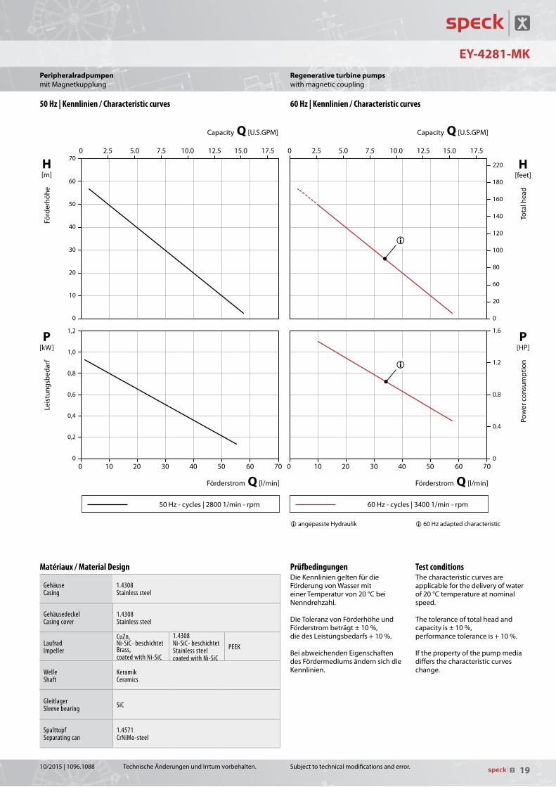
Regenerative turbine pumpswithmagneticcoupling
i60Hzadaptedcharacteristic
50 Hz | Kennlinien / Characteristic curves 60 Hz | Kennlinien / Characteristic curves
Matériaux / Material Design
GehäuseCasing
1.4308Stainless steel
Gehäusedeckel Casing cover
1.4308Stainless steel
LaufradImpeller
CuZn, Ni-SiC- beschichtetBrass, coated with Ni-SiC
1.4308 Ni-SiC- beschichtet Stainless steel coated with Ni-SiC
PEEK
WelleShaft
KeramikCeramics
GleitlagerSleeve bearing SiC
SpalttopfSeparating can
1.4571CrNiMo-steel
TechnischeÄnderungenundIrrtumvorbehalten.
P[kW]
Leis
tung
sbed
arf
H[m]
Förd
erhö
he
Förderstrom Q [l/min]Förderstrom Q [l/min]
PrüfbedingungenDieKennliniengeltenfürdieFörderungvonWassermiteinerTemperaturvon20°CbeiNenndrehzahl.
DieToleranzvonFörderhöheundFörderstrombeträgt±10%,diedesLeistungsbedarfs+10%.BeiabweichendenEigenschaftendesFördermediumsändernsichdieKennlinien.
PeripheralradpumpenmitMagnetkupplung
iangepassteHydraulik
10/2015|1096.1088

18
101
940
310515540932
211
161310515932
847515.1
341914550.1970565
847.1904 800
816 900932.1
182400.1230515.1
400
411*903*
550901
76
160 1,
3
177 2,
3
211 3
G 3/4
354 3
Ø 960
22
90115
11282
138
976
64
50
Ue*
EY-4281-MK
Subjecttotechnicalmodificationsanderror.
Regenerative turbine pumpswithmagneticcoupling
Maßzeichnung / Dimensional drawing
Schnittzeichnung / Cross-sectional drawing
Daten / DataBaugrößeFrame size
PhasenPhases 50 Hz / Cycles 60 Hz / Cycles Anschlüsse
ConnectionsDrehmomentTorque
GewichtWeight
WasserWater
ÖlOil
Type mm ~ 1/min kW HP 1/min kW HP GS GD Nm kg lbs tmax tmaxEY-4281-MK 71 3~ 2800 1,0 1,34 3400 1,1 1.5 G 3/4 G 3/4 7,0 12,5 28 140 °C 140 °C
Teileliste / Parts list101 Gehäuse Pump casing161 Gehäusedeckel Casing cover182 Fuß Foot211 Welle Shaft230 Laufrad Impeller310 Gleitlager Sleeve bearing341 Laterne Bracket400/.1 Dichtung Gasket411* Dichtring Sealing ring515/.1 Toleranzring Tolerance ring550/.1 Scheibe Washer540 Buchse Bush565 Niet Rivet800 Motor Motor816 Spalttopf Separating can847 Magnetkupplung (außen) Magnetic coupling (outer part)847.1 Magnetkupplung (innen) Magnetic coupling (inner part)900 Schraube Screw901 6-kt. Schraube Hexagon head screw903* Verschlussschraube Screw plug904 Gewindestift Threaded pin914 Innen-6-kt. Schraube Hexagon socket head screw932/.1 Sicherungsring Locking ring940 Passfeder Fitting key970 Typenschild Nameplate
1FlacherKlemmenkasten2HoherKlemmenkasten3AbhängigvonMotorausführung*AufAnfrageUe=Entleerung/Verschlussschraube-GewichtabhängigvonBaugröße,Leistung,WerkstoffenundAusführung
1Flatterminalbox2Highterminalbox3Dependingonthemotordesign*OnrequestUe=Drainage/ScrewplugWeightdependingonmotorframesize,performance,materialsandexecution
TechnischeÄnderungenundIrrtumvorbehalten.
PeripheralradpumpenmitMagnetkupplung
10/2015|1096.1088
19
EY-4281-MK
50Hz-cycles|28001/min-rpm 60Hz-cycles|34001/min-rpm
Leis
tung
sbed
arf
Puis
sanc
e ab
sorb
ée
Förderstrom / Débit Q [l/min] Förderstrom / Débit Q [l/min]
Capacity Q [U.S.GPM] Capacity Q [U.S.GPM]
Förd
erhö
he
Hau
teur
man
omét
rique
Tota
l hea
d Po
wer
con
sum
ptio
n
H [m]
P [kW]
P [HP]
H [feet]
70
60
50
40
30
20
10
0
1,2
1,0
0,8
0,6
0,4
0,2
0 0 10 20 30 40 50 60 70 0 10 20 30 40 50 60 70
1.6
1.2
0.8
0.4
0
220
180
160
140
120
100
80
60
20
0
0 2.5 5.0 7.5 10.0 12.5 15.0 17.5 0 2.5 5.0 7.5 10.0 12.5 15.0 17.5
50 Hz - cycles | 2800 1/min - rpm - tr/min 60 Hz - cycles | 3400 1/min - rpm - tr/min
�
�
� angepasste Hydraulik / adapted characteristic / caractéristique adaptée
Subjecttotechnicalmodificationsanderror.
H[feet]
Tota
lhea
d
P[HP]
Pow
erc
onsu
mpt
ion
Capacity Q [U.S.GPM]Capacity Q [U.S.GPM]
Test conditionsThecharacteristiccurvesareapplicableforthedeliveryofwaterof20°Ctemperatureatnominalspeed.
Thetoleranceoftotalheadandcapacityis±10%,performancetoleranceis+10%.
Ifthepropertyofthepumpmediadiffersthecharacteristiccurveschange.
Regenerative turbine pumpswithmagneticcoupling
i60Hzadaptedcharacteristic
50 Hz | Kennlinien / Characteristic curves 60 Hz | Kennlinien / Characteristic curves
Matériaux / Material Design
GehäuseCasing
1.4308Stainless steel
Gehäusedeckel Casing cover
1.4308Stainless steel
LaufradImpeller
CuZn, Ni-SiC- beschichtetBrass, coated with Ni-SiC
1.4308 Ni-SiC- beschichtet Stainless steel coated with Ni-SiC
PEEK
WelleShaft
KeramikCeramics
GleitlagerSleeve bearing SiC
SpalttopfSeparating can
1.4571CrNiMo-steel
TechnischeÄnderungenundIrrtumvorbehalten.
P[kW]
Leis
tung
sbed
arf
H[m]
Förd
erhö
he
Förderstrom Q [l/min]Förderstrom Q [l/min]
PrüfbedingungenDieKennliniengeltenfürdieFörderungvonWassermiteinerTemperaturvon20°CbeiNenndrehzahl.
DieToleranzvonFörderhöheundFörderstrombeträgt±10%,diedesLeistungsbedarfs+10%.BeiabweichendenEigenschaftendesFördermediumsändernsichdieKennlinien.
iangepassteHydraulik
PeripheralradpumpenmitMagnetkupplung
10/2015|1096.1088

20
NPY-2251-MK
18433083
9763
35GS GD
1512,
314
01, 3
133 80100 100
Ø7120
Ue* 7
3083
133
35
Ue*
100120
7
7
151
140
6355
GDGS
2, 3
1, 3
Ø
723400.2914.2
400
230940
161
211
310515
903*411*
901550
101 400.1 816847904
341914
515.1847.1
932540515.2
Subjecttotechnicalmodificationsanderror.
Regenerative turbine pumpswithmagneticcoupling
Maßzeichnung / Dimensional drawing
Schnittzeichnung / Cross-sectional drawing Teileliste / Parts list101 Gehäuse Casing161 Gehäusedeckel Casing cover211 Welle Shaft230 Laufrad Impeller310 Gleitlager Sleeve bearing341 Laterne Bracket400-.2 Dichtung Gasket411* Dichtring Sealing ring515-.2 Toleranzring Tolerance ring540 Buchse Bush550 Scheibe Washer723 Flansch Flange816 Spalttopf Separating can847 Magnetkupplung (außen) Magnetic coupling (outer part)847.1 Magnetkupplung (innen) Magnetic coupling (inner part)903* Verschlussschraube Screw plug904 Gewindestift Threaded pin914-.3 Innen-6-kt. Schraube Hexagon socket head screw932 Sicherungsring Locking ring940 Passfeder Fitting key
1FlacherKlemmenkasten2HoherKlemmenkasten3AbhängigvonMotorausführung*AufAnfrage
Ue=Entleerung/Verschlussschraube
GewichtabhängigvonBaugröße,Leistung,WerkstoffenundAusführung
1Flatterminalbox2Highterminalbox3Dependingonthemotordesign*Onrequest
Ue=Drainage/Screwplug
Weightdependingonmotorframesize,performance,materialsandexecution
Daten / DataBaugrößeFrame size
PhasenPhases 50 Hz / Cycles 60 Hz / Cycles Anschlüsse
ConnectionsDrehmomentTorque
GewichtWeight
WasserWater
ÖlOil
Type mm ~ 1/min kW HP 1/min kW HP GS GD Ue* Nm kg lbs tmax tmax
NPY-2251-MK 63 3~ 2800 0,50 0.67 3400 0,55 0.74 G 1/2 G 1/2 G 1/8 3,0 9,6 21 140 °C 180 °CSAE 1/2 SAE 1/2
TechnischeÄnderungenundIrrtumvorbehalten.
PeripheralradpumpenmitMagnetkupplung
10/2015|1096.1088

21
NPY-2251-MKLe
istu
ngsb
edar
f Pu
issa
nce
abso
rbée
Förderstrom / Débit Q [l/min] Förderstrom / Débit Q [l/min]
Capacity Q [U.S.GPM] Capacity Q [U.S.GPM]
Förd
erhö
he
Hau
teur
man
omét
rique
Tota
l hea
d Po
wer
con
sum
ptio
n
H [m]
P [kW]
P [HP]
H [feet]
60
50
40
30
20
10
0
0,6
0,5
0,4
0,3
0,2
0,1
0 0 5 10 15 20 25 30 0 5 10 15 20 25 30
0.8
0.7
0.6
0.5
0.4
0.3
0.2
0.1
0
175
150
125
100
75
50
25
0
0 1 2 3 4 5 6 7 0 1 2 3 4 5 6 7
50 Hz - cycles | 2800 1/min - rpm - tr/min 60 Hz - cycles | 3400 1/min - rpm - tr/min
�
�
� angepasste Hydraulik / adapted characteristic / caractéristique adaptée
50Hz-cycles|28001/min-rpm 60Hz-cycles|34001/min-rpm
Subjecttotechnicalmodificationsanderror.
H[feet]
Tota
lhea
d
P[HP]
Pow
erc
onsu
mpt
ion
Capacity Q [U.S.GPM]Capacity Q [U.S.GPM]
Test conditionsThecharacteristiccurvesareapplicableforthedeliveryofwaterof20°Ctemperatureatnominalspeed.
Thetoleranceoftotalheadandcapacityis±10%,performancetoleranceis+10%.
Ifthepropertyofthepumpmediadiffersthecharacteristiccurveschange.
Regenerative turbine pumpswithmagneticcoupling
i60Hzadaptedcharacteristic
50 Hz | Kennlinien / Characteristic curves 60 Hz | Kennlinien / Characteristic curves
Werkstoffausführungen / Material Design
GehäuseCasing
1.4581CrNiMo-cast steel
LaufradImpeller
1.4408, keramikbeschichtet CrNiMo-cast steel, coated with ceramics
1.4408, Ni-SiC-beschichtetCrNiMo-cast steel, Ni-SiC coated
PEEK
WelleShaft
Keramik Ceramics
SpalttopfSeparating can
1.4571CrNiMo-steel
TechnischeÄnderungenundIrrtumvorbehalten.
P[kW]
Leis
tung
sbed
arf
H[m]
Förd
erhö
he
Förderstrom Q [l/min]Förderstrom Q [l/min]
PrüfbedingungenDieKennliniengeltenfürdieFörderungvonWassermiteinerTemperaturvon20°CbeiNenndrehzahl.
DieToleranzvonFörderhöheundFörderstrombeträgt±10%,diedesLeistungsbedarfs+10%.BeiabweichendenEigenschaftendesFördermediumsändernsichdieKennlinien.
PeripheralradpumpenmitMagnetkupplung
i60HzangepassteHydraulik
10/2015|1096.1088

22
CY-4281-MK
55GS
H
HA
h3
GD
HD
KAAB
Ue*
BwBB
LB1o2
Z1
Ø
Subjecttotechnicalmodificationsanderror.
Regenerative turbine pumpswithmagneticcoupling
Maßzeichnung / Dimensional drawing
Schnittzeichnung / Cross-sectional drawing
Daten / DataBaugrößeFrame size
PhasenPhases 50 Hz / Cycles 60 Hz / Cycles Anschlüsse
ConnectionsDrehmomentTorque
GewichtWeight
WasserWater
ÖlOil
Type mm ~ 1/min kW HP 1/min kW HP GS GD Ue* Nm kg lbs tmax
CY-4281-MK 713~ 2800
1,0 1.343400
1,0 1.34G 3/4 G 3/4 G 1/8
7 15,0 33140 °C 180 °C80 1,5 2.00 1,5 2.00 7 18,5 41
90 2,2 2.95 2,2 2.95 10 19,5 43
Type Baugröße A AB B BB H HA HD K LB1 h3 o2 w z1
CY-4281-MK 71 112 135 90 110 71 8 175 9 211 145 – 178 36780 125 153 100 125 80 10 194 9 240 154 10 191 41490 140 170 125 155 90 13 209 10 281 164 14 206 444
Teileliste / Parts list101 Gehäuse Casing161 Gehäusedeckel Casing cover211 Welle Shaft230 Laufrad Impeller310 Gleitlager Sleeve bearing341 Laterne Bracket400/.1 Dichtung Gasket411* Dichtring Sealing ring515/.1 Toleranzring Tolerance ring540 Wellenbuchse Shaft bush550 Scheibe Washer723.21 Flansch Flange816 Spalttopf Separating can847 Magnetkupplung (außen) Magnetic coupling (outer part)847.1 Magnetkupplung (innen) Magnetic coupling (inner part)901-.2 6-kt. Schraube Hexagon head screw903* Verschlussschraube Screw plug904 Gewindestift Threaded pin914 Innen-6-kt. Schraube Hexagon socket head screw932 Sicherungsring Locking ring940 Passfeder Fitting key
1AbhängigvonMotorausführung2Motorflansch0120
*AufAnfrage
Ue=Entleerung/Verschlussschraube
GewichtabhängigvonBaugröße,Leistung,WerkstoffenundAusführung
1Dependingonthemotordesign2Motorflange0120
*Onrequest
Ue=Drainage/Screwplug
Weightdependingonmotorframesize,performance,materialsandexecution
TechnischeÄnderungenundIrrtumvorbehalten.
PeripheralradpumpenmitMagnetkupplung
10/2015|1096.1088

23
CY-4281-MK
50Hz-cycles|28001/min-rpm 60Hz-cycles|34001/min-rpm
Leis
tung
sbed
arf
Puis
sanc
e ab
sorb
ée
Förderstrom / Débit Q [l/min] Förderstrom / Débit Q [l/min]
Capacity Q [U.S.GPM] Capacity Q [U.S.GPM]
Förd
erhö
he
Hau
teur
man
omét
rique
Tota
l hea
d Po
wer
con
sum
ptio
n
H [m]
P [kW]
P [HP]
H [feet]
100
90
80
70
60
50
40
30
20
10
0
2,00
1,75
1,50
1,25
1,00
0,75
0,50
0,25
0 0 10 20 30 40 50 60 70 80 90 100 0 10 20 30 40 50 60 70 80 90 100
2.5
2.0
1.5
1.0
0.5
0
300
250
200
150
100
50
0
0 3 6 9 12 15 18 21 24 0 3 6 9 12 15 18 21 24
50 Hz - cycles | 2800 1/min - rpm - tr/min 60 Hz - cycles | 3400 1/min - rpm - tr/min
Q 60
Q 30
Q 30
Q 90
Q 60
Q 90
Q 60 �Q 30 �
Q 30 �
Q 90 �
Q 60 �
Q 90 �
� angepasste Hydraulik / adapted characteristic / caractéristique adaptée
Subjecttotechnicalmodificationsanderror.
H[feet]
Tota
lhea
d
P[HP]
Pow
erc
onsu
mpt
ion
Capacity Q [U.S.GPM]Capacity Q [U.S.GPM]
Test conditionsThecharacteristiccurvesareapplicableforthedeliveryofwaterof20°Ctemperatureatnominalspeed.
Thetoleranceoftotalheadandcapacityis±10%,performancetoleranceis+10%.
Ifthepropertyofthepumpmediadiffersthecharacteristiccurveschange.
Regenerative turbine pumpswithmagneticcoupling
i60Hzadaptedcharacteristic
50 Hz | Kennlinien / Characteristic curves 60 Hz | Kennlinien / Characteristic curves
Werkstoffausführungen / Material Design
GehäuseCasing
1.4581CrNiMo-cast steel
LaufradImpeller
1.4408, keramikbeschichtet CrNiMo-cast steel, coated with ceramics
1.4408, Ni-SiC-beschichtetCrNiMo-cast steel, Ni-SiC coated
PEEK
WelleShaft
KeramikCeramics
SpalttopfSeparating can
1.4571CrNiMo-steel
TechnischeÄnderungenundIrrtumvorbehalten.
P[kW]
Leis
tung
sbed
arf
H[m]
Förd
erhö
he
Förderstrom Q [l/min]Förderstrom Q [l/min]
PrüfbedingungenDieKennliniengeltenfürdieFörderungvonWassermiteinerTemperaturvon20°CbeiNenndrehzahl.
DieToleranzvonFörderhöheundFörderstrombeträgt±10%,diedesLeistungsbedarfs+10%.BeiabweichendenEigenschaftendesFördermediumsändernsichdieKennlinien.
PeripheralradpumpenmitMagnetkupplung
i60HzangepassteHydraulik
10/2015|1096.1088

24
1
1 1
AD1
CY-6091-MK
Subjecttotechnicalmodificationsanderror.
Regenerative turbine pumpswithmagneticcoupling
Maßzeichnung / Dimensional drawing
Schnittzeichnung / Cross-sectional drawing
Daten / DataBaugrößeFrame size
PhasenPhases 50 Hz / Cycles 60 Hz / Cycles Gewicht
WeightWasserWater
ÖlOil Fluorinert™
Type mm ~ 1/min kW HP 1/min kW HP kg lbs tmax tmax tmaxCY-6091-MK 90L
3~ 2800
2,80 3.75
3400
2,80 3.75 33 73
140 °C 180 °C - 60 °C ... 200 °C100L 3,00 4.02 3,00 4.02 36 79112M 4,00 5.36 4,00 5.36 46 101132S 5,50 7.38 5,50 7.38 70 155
Type Baugröße Q l/min USGPM GS GD Nm AD1 LB1 h1 h3 h5 m1 m2 n1 o1 w z1
CY-6091-MK 90L Q 80 80 21
SAE 1 SAE 114 147 280
100 200 138 110 70 130–
80501
100L Q 150 150 37 154 306 10 537
22
32 559
112M 167 296 114 214138
145 80 140 – 90578
Q 200 200 53 SAE 1 1/4 SAE 1 1/4 143 582132S 221 457 20 739
Teileliste / Parts list101 Gehäuse Casing161 Gehäusedeckel Casing cover211 Welle Shaft230 Laufrad Impeller310 Gleitlager Sleeve bearing341 Laterne Bracket400-.2 Dichtung Gasket515-.2 Toleranzring Tolerance ring562 Stift Pin723 Flansch Flange816 Spalttopf Separating can847 Magnetkupplung (außen) Magnetic coupling (outer part)847.1 Magnetkupplung (innen) Magnetic coupling (inner part)901/.1 6-kt. Schraube Hexagon head screw904 Gewindestift Threaded pin914-.2 Innen-6-kt. Schraube Hexagon socket head screw920 6-kt. Mutter Hexagon nut
1AbhängigvonMotorausführung
GewichtabhängigvonBaugröße,Leistung,WerkstoffenundAusführung
1Dependingonthemotordesign
Weightdependingonmotorframesize,performance,materialsandexecution
TechnischeÄnderungenundIrrtumvorbehalten.
PeripheralradpumpenmitMagnetkupplung
10/2015|1096.1088

25
50Hz-cycles|28001/min-rpm 60Hz-cycles|34001/min-rpm
Leis
tung
sbed
arf
Puis
sanc
e ab
sorb
ée
Förderstrom / Débit Q [l/min] Förderstrom / Débit Q [l/min]
Capacity Q [U.S.GPM] Capacity Q [U.S.GPM]
Förd
erhö
he
Hau
teur
man
omét
rique
Tota
l hea
d Po
wer
con
sum
ptio
n
H [m]
P [kW]
P [HP]
H [feet]
100
80
60
40
20
0
6
5
4
3
2
1
0 0 20 40 60 80 100 120 140 160 180 200 0 20 40 60 80 100 120 140 160 180 200
8
7
6
5
4
3
2
1
0
300
250
200
150
100
50
0
0 5 10 15 20 25 30 35 40 45 50 0 5 10 15 20 25 30 35 40 45 50
50 Hz - cycles | 2800 1/min - rpm - tr/min 60 Hz - cycles | 3400 1/min - rpm - tr/min
Q 80
Q 150
Q 200
Q 80 �
Q 150 �
Q 200 �
Q 80
Q 150
Q 200
Q 80 �
Q 150 �
Q 200 �
� angepasste Hydraulik / adapted characteristic / caractéristique adaptée
CY-6091-MK
Subjecttotechnicalmodificationsanderror.
H[feet]
Tota
lhea
d
P[HP]
Pow
erc
onsu
mpt
ion
Capacity Q [U.S.GPM]Capacity Q [U.S.GPM]
Test conditionsThecharacteristiccurvesareapplicableforthedeliveryofwaterof20°Ctemperatureatnominalspeed.
Thetoleranceoftotalheadandcapacityis±10%,performancetoleranceis+10%.
Ifthepropertyofthepumpmediadiffersthecharacteristiccurveschange.
Regenerative turbine pumpswithmagneticcoupling
i60Hzadaptedcharacteristic
50 Hz | Kennlinien / Characteristic curves 60 Hz | Kennlinien / Characteristic curves
Werkstoffausführungen / Material Design
GehäuseCasing
1.4581CrNiMo-cast steel
LaufradImpeller
1.4408, keramikbeschichtetCrNiMo-cast steel, coated with ceramics
WelleShaft
KeramikCeramics
SpalttopfSeparating can
1.4571CrNiMo-steel
TechnischeÄnderungenundIrrtumvorbehalten.
P[kW]
Leis
tung
sbed
arf
H[m]
Förd
erhö
he
Förderstrom Q [l/min]Förderstrom Q [l/min]
PrüfbedingungenDieKennliniengeltenfürdieFörderungvonWassermiteinerTemperaturvon20°CbeiNenndrehzahl.
DieToleranzvonFörderhöheundFörderstrombeträgt±10%,diedesLeistungsbedarfs+10%.BeiabweichendenEigenschaftendesFördermediumsändernsichdieKennlinien.
PeripheralradpumpenmitMagnetkupplung
i60HzangepassteHydraulik
10/2015|1096.1088

26
33 3
2, 3
1, 3 2, 3
1, 3
NPY-2251-MK-HT
Subjecttotechnicalmodificationsanderror.
Heat transfer pumps with peripheral impellerwithmagneticcoupling
Maßzeichnung / Dimensional drawing
Schnittzeichnung / Cross-sectional drawing
Daten / DataBaugrößeFrame size
PhasenPhases 50 Hz / Cycles 60 Hz / Cycles Anschlüsse
ConnectionsDrehmomentTorque
GewichtWeight
WasserWater
Type mm ~ 1/min kW HP 1/min kW HP GS GD Ue* Nm kg lbs tmax
NPY-2251-MK-HT 63 3~ 2800 0,50 0.67 3400 0,55 0.74 G 1/2 G 1/2 G 1/8 3,0 9,6 21 180 °CSAE 1/2 SAE 1/2
Teileliste / Parts list101 Gehäuse Casing161 Gehäusedeckel Casing cover211 Welle Shaft230 Laufrad Impeller310 Gleitlager Sleeve bearing341 Laterne Bracket400/.2 Dichtung Gasket411* Dichtring Sealing ring515-.2 Toleranzring Tolerance ring540 Buchse Bush723 Flansch Flange816 Spalttopf Separating can847 Magnetkupplung (außen) Magnetic coupling (outer part)847.1 Magnetkupplung (innen) Magnetic coupling (inner part)903* Verschlussschraube Screw plug904 Gewindestift Threaded pin914-.3 Innen-6-kt. Schraube Hexagon socket head screw932 Sicherungsring Locking ring940 Passfeder Fitting key
*AufAnfrage
1FlacherKlemmenkasten2HoherKlemmenkasten3AbhängigvonMotorausführung
Ue=Entleerung/Verschlussschraube
GewichtabhängigvonBaugröße,Leistung,WerkstoffenundAusführung
*Onrequest
1Flatterminalbox2Highterminalbox3Dependingonthemotordesign
Ue=Drainage/Screwplug
Weightdependingonmotorframesize,performance,materialsandexecution
TechnischeÄnderungenundIrrtumvorbehalten.
Wärmeträgerpumpen mit PeripheralradmitMagnetkupplung
10/2015|1096.1088

27
NPY-2251-MK-HT
50Hz-cycles|28001/min-rpm 60Hz-cycles|34001/min-rpm
Leis
tung
sbed
arf
Puis
sanc
e ab
sorb
ée
Förderstrom / Débit Q [l/min] Förderstrom / Débit Q [l/min]
Capacity Q [U.S.GPM] Capacity Q [U.S.GPM]
Förd
erhö
he
Hau
teur
man
omét
rique
Tota
l hea
d Po
wer
con
sum
ptio
n
H [m]
P [kW]
P [HP]
H [feet]
60
50
40
30
20
10
0
0,6
0,5
0,4
0,3
0,2
0,1
0 0 5 10 15 20 25 30 0 5 10 15 20 25 30
0.8
0.7
0.6
0.5
0.4
0.3
0.2
0.1
0
175
150
125
100
75
50
25
0
0 1 2 3 4 5 6 7 0 1 2 3 4 5 6 7
50 Hz - cycles | 2800 1/min - rpm - tr/min 60 Hz - cycles | 3400 1/min - rpm - tr/min
�
�
� angepasste Hydraulik / adapted characteristic / caractéristique adaptée
Subjecttotechnicalmodificationsanderror.
H[feet]
Tota
lhea
d
P[HP]
Pow
erc
onsu
mpt
ion
Capacity Q [U.S.GPM]Capacity Q [U.S.GPM]
Test conditionsThecharacteristiccurvesareapplicableforthedeliveryofwaterof20°Ctemperatureatnominalspeed.
Thetoleranceoftotalheadandcapacityis±10%,performancetoleranceis+10%.
Ifthepropertyofthepumpmediadiffersthecharacteristiccurveschange.
Heat transfer pumps with peripheral impellerwithmagneticcoupling
i60Hzadaptedcharacteristic
50 Hz | Kennlinien / Characteristic curves 60 Hz | Kennlinien / Characteristic curves
Werkstoffausführungen / Material Design
GehäuseCasing
1.4581CrNiMo-cast steel
LaufradImpeller
1.4408, keramikbeschichtet CrNiMo-cast steel, coated with ceramics
1.4408, Ni-SiC-beschichtetCrNiMo-cast steel, Ni-SiC coated
PEEK
WelleShaft
KeramikCeramics
SpalttopfSeparating can
1.4571CrNiMo-steel
TechnischeÄnderungenundIrrtumvorbehalten.
P[kW]
Leis
tung
sbed
arf
H[m]
Förd
erhö
he
Förderstrom Q [l/min]Förderstrom Q [l/min]
PrüfbedingungenDieKennliniengeltenfürdieFörderungvonWassermiteinerTemperaturvon20°CbeiNenndrehzahl.
DieToleranzvonFörderhöheundFörderstrombeträgt±10%,diedesLeistungsbedarfs+10%.BeiabweichendenEigenschaftendesFördermediumsändernsichdieKennlinien.
Wärmeträgerpumpen mit PeripheralradmitMagnetkupplung
i60HzangepassteHydraulik
10/2015|1096.1088
28
2
CY-4281-MK-HT
Subjecttotechnicalmodificationsanderror.
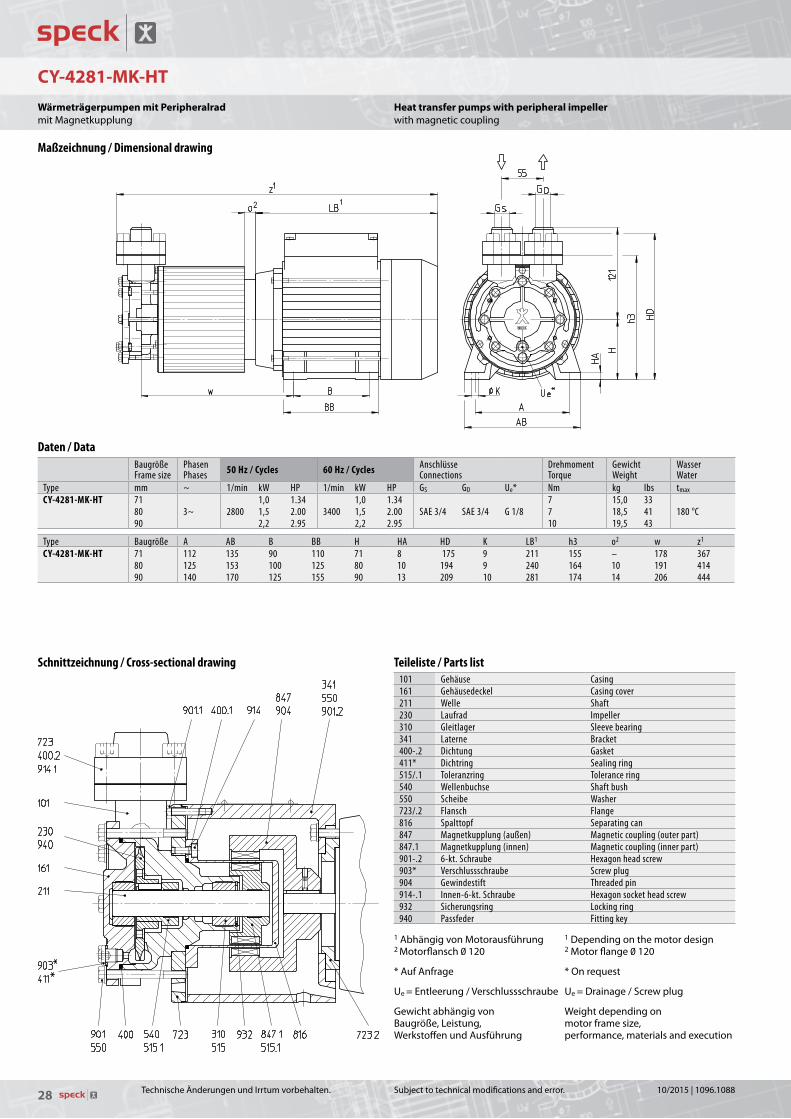
Heat transfer pumps with peripheral impellerwithmagneticcoupling
Maßzeichnung / Dimensional drawing
Schnittzeichnung / Cross-sectional drawing Teileliste / Parts list101 Gehäuse Casing161 Gehäusedeckel Casing cover211 Welle Shaft230 Laufrad Impeller310 Gleitlager Sleeve bearing341 Laterne Bracket400-.2 Dichtung Gasket411* Dichtring Sealing ring515/.1 Toleranzring Tolerance ring540 Wellenbuchse Shaft bush 550 Scheibe Washer723/.2 Flansch Flange816 Spalttopf Separating can847 Magnetkupplung (außen) Magnetic coupling (outer part)847.1 Magnetkupplung (innen) Magnetic coupling (inner part)901-.2 6-kt. Schraube Hexagon head screw903* Verschlussschraube Screw plug904 Gewindestift Threaded pin914-.1 Innen-6-kt. Schraube Hexagon socket head screw932 Sicherungsring Locking ring940 Passfeder Fitting key
1AbhängigvonMotorausführung2Motorflansch0120
*AufAnfrage
Ue=Entleerung/Verschlussschraube
GewichtabhängigvonBaugröße,Leistung,WerkstoffenundAusführung
1Dependingonthemotordesign2Motorflange0120
*Onrequest
Ue=Drainage/Screwplug
Weightdependingonmotorframesize,performance,materialsandexecution
Daten / DataBaugrößeFrame size
PhasenPhases 50 Hz / Cycles 60 Hz / Cycles Anschlüsse
ConnectionsDrehmomentTorque
GewichtWeight
WasserWater
Type mm ~ 1/min kW HP 1/min kW HP GS GD Ue* Nm kg lbs tmax
CY-4281-MK-HT 713~ 2800
1,0 1.343400
1,0 1.34SAE 3/4 SAE 3/4 G 1/8
7 15,0 33180 °C80 1,5 2.00 1,5 2.00 7 18,5 41
90 2,2 2.95 2,2 2.95 10 19,5 43
Type Baugröße A AB B BB H HA HD K LB1 h3 o2 w z1
CY-4281-MK-HT 71 112 135 90 110 71 8 175 9 211 155 – 178 36780 125 153 100 125 80 10 194 9 240 164 10 191 41490 140 170 125 155 90 13 209 10 281 174 14 206 444
TechnischeÄnderungenundIrrtumvorbehalten.
Wärmeträgerpumpen mit PeripheralradmitMagnetkupplung
10/2015|1096.1088

29
CY-4281-MK-HT
50Hz-cycles|28001/min-rpm 60Hz-cycles|34001/min-rpm
Leis
tung
sbed
arf
Puis
sanc
e ab
sorb
ée
Förderstrom / Débit Q [l/min] Förderstrom / Débit Q [l/min]
Capacity Q [U.S.GPM] Capacity Q [U.S.GPM]
Förd
erhö
he
Hau
teur
man
omét
rique
Tota
l hea
d Po
wer
con
sum
ptio
n
H [m]
P [kW]
P [HP]
H [feet]
100
90
80
70
60
50
40
30
20
10
0
2,00
1,75
1,50
1,25
1,00
0,75
0,50
0,25
0 0 10 20 30 40 50 60 70 80 90 100 0 10 20 30 40 50 60 70 80 90 100
2.5
2.0
1.5
1.0
0.5
0
300
250
200
150
100
50
0
0 3 6 9 12 15 18 21 24 0 3 6 9 12 15 18 21 24
50 Hz - cycles | 2800 1/min - rpm - tr/min 60 Hz - cycles | 3400 1/min - rpm - tr/min
Q 60
Q 30
Q 30
Q 90
Q 60
Q 90
Q 60 �Q 30 �
Q 30 �
Q 90 �
Q 60 �
Q 90 �
� angepasste Hydraulik / adapted characteristic / caractéristique adaptée
Subjecttotechnicalmodificationsanderror.
H[feet]
Tota
lhea
d
P[HP]
Pow
erc
onsu
mpt
ion
Capacity Q [U.S.GPM]Capacity Q [U.S.GPM]
Test conditionsThecharacteristiccurvesareapplicableforthedeliveryofwaterof20°Ctemperatureatnominalspeed.
Thetoleranceoftotalheadandcapacityis±10%,performancetoleranceis+10%.
Ifthepropertyofthepumpmediadiffersthecharacteristiccurveschange.
Heat transfer pumps with peripheral impellerwithmagneticcoupling
i60Hzadaptedcharacteristic
50 Hz | Kennlinien / Characteristic curves 60 Hz | Kennlinien / Characteristic curves
Werkstoffausführungen / Material Design
GehäuseCasing
1.4581CrNiMo-cast steel
LaufradImpeller
1.4408, keramikbeschichtetCrNiMo-cast steel, coated with ceramics
1.4408, Ni-SiC-beschichtetCrNiMo-cast steel, Ni-SiC coated
WelleShaft
Keramik Ceramics
SpalttopfSeparating can
1.4571CrNiMo-steel
TechnischeÄnderungenundIrrtumvorbehalten.
P[kW]
Leis
tung
sbed
arf
H[m]
Förd
erhö
he
Förderstrom Q [l/min]Förderstrom Q [l/min]
PrüfbedingungenDieKennliniengeltenfürdieFörderungvonWassermiteinerTemperaturvon20°CbeiNenndrehzahl.
DieToleranzvonFörderhöheundFörderstrombeträgt±10%,diedesLeistungsbedarfs+10%.BeiabweichendenEigenschaftendesFördermediumsändernsichdieKennlinien.
Wärmeträgerpumpen mit PeripheralradmitMagnetkupplung
i60HzangepassteHydraulik
10/2015|1096.1088

30
1
1
1 1
CY-6091-MK-HT
Subjecttotechnicalmodificationsanderror.
Heat transfer pumps with peripheral impellerwithmagneticcoupling
Maßzeichnung / Dimensional drawing
Schnittzeichnung / Cross-sectional drawing Teileliste / Parts list101 Gehäuse Casing161 Gehäusedeckel Casing cover211 Welle Shaft230 Laufrad Impeller310 Gleitlager Sleeve bearing341 Laterne Bracket400-.2 Dichtung Gasket515-.2 Toleranzring Tolerance ring562 Stift Pin723 Flansch Flange816 Spalttopf Separating can847 Magnetkupplung (außen) Magnetic coupling (outer part)847.1 Magnetkupplung (innen) Magnetic coupling (inner part)901/.1 6-kt. Schraube Hexagon head screw904 Gewindestift Threaded pin914-.2 Innen-6-kt. Schraube Hexagon socket head screw920 6-kt. Mutter Hexagon nut
1AbhängigvonMotorausführung
GewichtabhängigvonBaugröße,Leistung,WerkstoffenundAusführung
1Dependingonthemotordesign
Weightdependingonmotorframesize,performance,materialsandexecution
Daten / DataBaugrößeFrame size
PhasenPhases 50 Hz / Cycles 60 Hz / Cycles Gewicht
WeightWasserWater
WasserWater
Type mm ~ 1/min kW HP 1/min kW HP kg lbs tmax tmaxCY-6091-MK 90L
3~ 2800
2,80 3.75
3400
2,80 3.75 33 73180 °C (G)
180 °C (SAE)
100L 3,00 4.02 3,00 4.02 36 79112M 4,00 5.36 4,00 5.36 46 101132S 5,50 7.38 5,50 7.38 70 155
Type Baugröße Q l/min USGPM GS GD Nm AD1 LB1 h1 h3 h5 m1 m2 n1 o1 w z1
CY-6091-MK 90L Q 80 80 21G 3/4oder / orSAE 1
G 3/4oder / orSAE 1
14 147 280100 200 138 110 70 130
–80
501
100L Q 150 150 37 154 306 10 537
22
32 559
112M 167 296 114 214138
145 80 140 – 90578
Q 200 200 53 SAE 1 1/4 SAE 1 1/4 143 582132S 221 457 20 739
TechnischeÄnderungenundIrrtumvorbehalten.
Wärmeträgerpumpen mit PeripheralradmitMagnetkupplung
10/2015|1096.1088
31
CY-6091-MK-HT
50Hz-cycles|28001/min-rpm 60Hz-cycles|34001/min-rpm
Leis
tung
sbed
arf
Puis
sanc
e ab
sorb
ée
Förderstrom / Débit Q [l/min] Förderstrom / Débit Q [l/min]
Capacity Q [U.S.GPM] Capacity Q [U.S.GPM]
Förd
erhö
he
Hau
teur
man
omét
rique
Tota
l hea
d Po
wer
con
sum
ptio
n
H [m]
P [kW]
P [HP]
H [feet]
100
80
60
40
20
0
6
5
4
3
2
1
0 0 20 40 60 80 100 120 140 160 180 200 0 20 40 60 80 100 120 140 160 180 200
8
7
6
5
4
3
2
1
0
300
250
200
150
100
50
0
0 5 10 15 20 25 30 35 40 45 50 0 5 10 15 20 25 30 35 40 45 50
50 Hz - cycles | 2800 1/min - rpm - tr/min 60 Hz - cycles | 3400 1/min - rpm - tr/min
Q 80
Q 150
Q 200
Q 80 �
Q 150 �
Q 200 �
Q 80
Q 150
Q 200
Q 80 �
Q 150 �
Q 200 �
� angepasste Hydraulik / adapted characteristic / caractéristique adaptée
Subjecttotechnicalmodificationsanderror.
H[feet]
Tota
lhea
d
P[HP]
Pow
erc
onsu
mpt
ion
Capacity Q [U.S.GPM]Capacity Q [U.S.GPM]
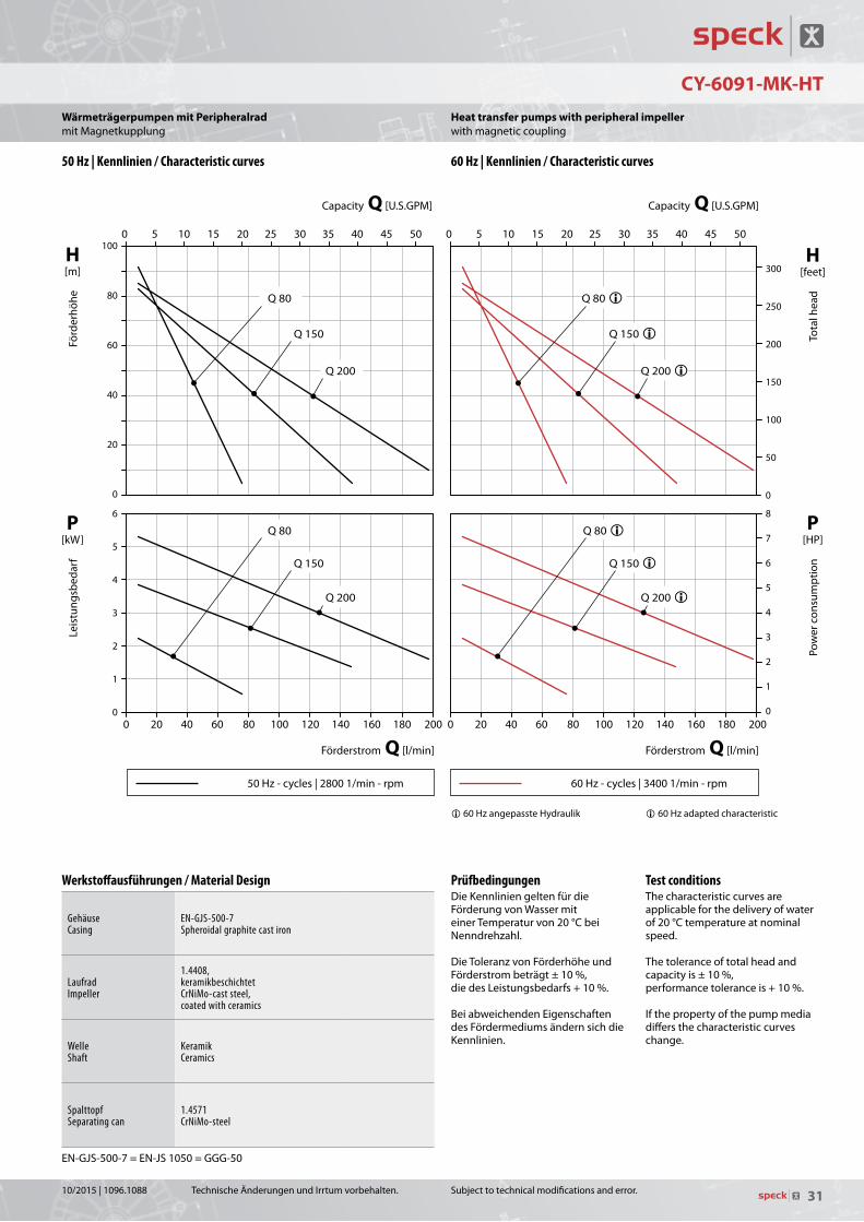
Test conditionsThecharacteristiccurvesareapplicableforthedeliveryofwaterof20°Ctemperatureatnominalspeed.
Thetoleranceoftotalheadandcapacityis±10%,performancetoleranceis+10%.
Ifthepropertyofthepumpmediadiffersthecharacteristiccurveschange.
Heat transfer pumps with peripheral impellerwithmagneticcoupling
i60Hzadaptedcharacteristic
50 Hz | Kennlinien / Characteristic curves 60 Hz | Kennlinien / Characteristic curves
Werkstoffausführungen / Material Design
GehäuseCasing
EN-GJS-500-7Spheroidal graphite cast iron
LaufradImpeller
1.4408, keramikbeschichtetCrNiMo-cast steel, coated with ceramics
WelleShaft
KeramikCeramics
SpalttopfSeparating can
1.4571CrNiMo-steel
EN-GJS-500-7=EN-JS1050=GGG-50
TechnischeÄnderungenundIrrtumvorbehalten.
P[kW]
Leis
tung
sbed
arf
H[m]
Förd
erhö
he
Förderstrom Q [l/min]Förderstrom Q [l/min]
PrüfbedingungenDieKennliniengeltenfürdieFörderungvonWassermiteinerTemperaturvon20°CbeiNenndrehzahl.
DieToleranzvonFörderhöheundFörderstrombeträgt±10%,diedesLeistungsbedarfs+10%.BeiabweichendenEigenschaftendesFördermediumsändernsichdieKennlinien.
Wärmeträgerpumpen mit PeripheralradmitMagnetkupplung
i60HzangepassteHydraulik
10/2015|1096.1088

32
33 3
2, 3
1, 3 2, 3
1, 3
NPY-2251-MK-TOE
Subjecttotechnicalmodificationsanderror.
Heat transfer pumps with peripheral impellerwithmagneticcoupling
Maßzeichnung / Dimensional drawing
Schnittzeichnung / Cross-sectional drawing
Daten / DataBaugrößeFrame size
PhasenPhases 50 Hz / Cycles 60 Hz / Cycles Anschlüsse
ConnectionsDrehmomentTorque
GewichtWeight
ÖlOil
ÖlOil
Type mm ~ 1/min kW HP 1/min kW HP GS GD Ue* Nm kg lbs tmax tmax
NPY-2251-MK-TOE 63 3~ 2800 0,50 0.67 3400 0,55 0.74 G 1/2 G 1/2 G 1/8 3,0 9,6 21 180 °C (G 1/2)
350 °C (SAE 1/2)SAE 1/2 SAE 1/2
Teileliste / Parts list101 Gehäuse Casing161 Gehäusedeckel Casing cover211 Welle Shaft230 Laufrad Impeller310 Gleitlager Sleeve bearing341 Laterne Bracket400/.2 Dichtung Gasket411* Dichtring Sealing ring515-.2 Toleranzring Tolerance ring540 Buchse Bush723 Flansch Flange816 Spalttopf Separating can847 Magnetkupplung (außen) Magnetic coupling (outer part)847.1 Magnetkupplung (innen) Magnetic coupling (inner part)903* Verschlussschraube Screw plug904 Gewindestift Threaded pin914-.3 Innen-6-kt. Schraube Hexagon socket head screw932 Sicherungsring Locking ring940 Passfeder Fitting key
*AufAnfrage
1FlacherKlemmenkasten2HoherKlemmenkasten3AbhängigvonMotorausführung
Ue=Entleerung/Verschlussschraube
GewichtabhängigvonBaugröße,Leistung,WerkstoffenundAusführung
*Onrequest
1Flatterminalbox2Highterminalbox3Dependingonthemotordesign
Ue=Drainage/Screwplug
Weightdependingonmotorframesize,performance,materialsandexecution
TechnischeÄnderungenundIrrtumvorbehalten.
Wärmeträgerpumpen mit PeripheralradmitMagnetkupplung
10/2015|1096.1088

33
NPY-2251-MK-TOE
50Hz-cycles|28001/min-rpm 60Hz-cycles|34001/min-rpm
Leis
tung
sbed
arf
Puis
sanc
e ab
sorb
ée
Förderstrom / Débit Q [l/min] Förderstrom / Débit Q [l/min]
Capacity Q [U.S.GPM] Capacity Q [U.S.GPM]
Förd
erhö
he
Hau
teur
man
omét
rique
Tota
l hea
d Po
wer
con
sum
ptio
n
H [m]
P [kW]
P [HP]
H [feet]
60
50
40
30
20
10
0
0,6
0,5
0,4
0,3
0,2
0,1
0 0 5 10 15 20 25 30 0 5 10 15 20 25 30
0.8
0.7
0.6
0.5
0.4
0.3
0.2
0.1
0
175
150
125
100
75
50
25
0
0 1 2 3 4 5 6 7 0 1 2 3 4 5 6 7
50 Hz - cycles | 2800 1/min - rpm - tr/min 60 Hz - cycles | 3400 1/min - rpm - tr/min
�
�
� angepasste Hydraulik / adapted characteristic / caractéristique adaptée
Subjecttotechnicalmodificationsanderror.
H[feet]
Tota
lhea
d
P[HP]
Pow
erc
onsu
mpt
ion
Capacity Q [U.S.GPM]Capacity Q [U.S.GPM]
Test conditionsThecharacteristiccurvesareapplicableforthedeliveryofwaterof20°Ctemperatureatnominalspeed.
Thetoleranceoftotalheadandcapacityis±10%,performancetoleranceis+10%.
Ifthepropertyofthepumpmediadiffersthecharacteristiccurveschange.
Heat transfer pumps with peripheral impellerwithmagneticcoupling
i60Hzadaptedcharacteristic
50 Hz | Kennlinien / Characteristic curves 60 Hz | Kennlinien / Characteristic curves
Werkstoffausführungen / Material Design
GehäuseCasing
1.4581CrNiMo-cast steel
LaufradImpeller
1.4408, Ni-SiC-beschichtetCrNiMo-cast steel, Ni-SiC coated
WelleShaft
KeramikCeramics
SpalttopfSeparating can
1.4571CrNiMo-steel
TechnischeÄnderungenundIrrtumvorbehalten.
P[kW]
Leis
tung
sbed
arf
H[m]
Förd
erhö
he
Förderstrom Q [l/min]Förderstrom Q [l/min]
PrüfbedingungenDieKennliniengeltenfürdieFörderungvonWassermiteinerTemperaturvon20°CbeiNenndrehzahl.
DieToleranzvonFörderhöheundFörderstrombeträgt±10%,diedesLeistungsbedarfs+10%.BeiabweichendenEigenschaftendesFördermediumsändernsichdieKennlinien.
Wärmeträgerpumpen mit PeripheralradmitMagnetkupplung
i60HzangepassteHydraulik
10/2015|1096.1088

34
2
CY-4281-MK-TOE
Subjecttotechnicalmodificationsanderror.
Heat transfer pumps with peripheral impellerwithmagneticcoupling
Maßzeichnung / Dimensional drawing
Schnittzeichnung / Cross-sectional drawing Teileliste / Parts list101 Gehäuse Casing161 Gehäusedeckel Casing cover211 Welle Shaft230 Laufrad Impeller310 Gleitlager Sleeve bearing341 Laterne Bracket400-.2 Dichtung Gasket411* Dichtring Sealing ring515/.1 Toleranzring Tolerance ring540 Wellenbuchse Shaft bush 550 Scheibe Washer723/.2 Flansch Flange816 Spalttopf Separating can847 Magnetkupplung (außen) Magnetic coupling (outer part)847.1 Magnetkupplung (innen) Magnetic coupling (inner part)901-.2 6-kt. Schraube Hexagon head screw903* Verschlussschraube Screw plug904 Gewindestift Threaded pin914-.1 Innen-6-kt. Schraube Hexagon socket head screw932 Sicherungsring Locking ring940 Passfeder Fitting key
1AbhängigvonMotorausführung2Motorflansch0120
*AufAnfrage
Ue=Entleerung/Verschlussschraube
GewichtabhängigvonBaugröße,Leistung,WerkstoffenundAusführung
1Dependingonthemotordesign2Motorflange0120
*Onrequest
Ue=Drainage/Screwplug
Weightdependingonmotorframesize,performance,materialsandexecution
Daten / DataBaugrößeFrame size
PhasenPhases 50 Hz / Cycles 60 Hz / Cycles Anschlüsse
ConnectionsDrehmomentTorque
GewichtWeight
ÖlOil
Type mm ~ 1/min kW HP 1/min kW HP GS GD Ue* Nm kg lbs tmax
CY-4281-MK-TOE 713~ 2800
1,0 1.343400
1,0 1.34SAE 3/4 SAE 3/4 G 1/8
7 15,0 33350 °C80 1,5 2.00 1,5 2.00 7 18,5 41
90 2,2 2.95 2,2 2.95 10 19,5 43
Type Baugröße A AB B BB H HA HD K LB1 h3 o2 w z1
CY-4281-MK-TOE 71 112 135 90 110 71 8 175 9 211 155 – 178 36780 125 153 100 125 80 10 194 9 240 164 10 191 41490 140 170 125 155 90 13 209 10 281 174 14 206 444
TechnischeÄnderungenundIrrtumvorbehalten.
Wärmeträgerpumpen mit PeripheralradmitMagnetkupplung
10/2015|1096.1088

35
CY-4281-MK-TOE
50Hz-cycles|28001/min-rpm 60Hz-cycles|34001/min-rpm
Leis
tung
sbed
arf
Puis
sanc
e ab
sorb
ée
Förderstrom / Débit Q [l/min] Förderstrom / Débit Q [l/min]
Capacity Q [U.S.GPM] Capacity Q [U.S.GPM]
Förd
erhö
he
Hau
teur
man
omét
rique
Tota
l hea
d Po
wer
con
sum
ptio
n
H [m]
P [kW]
P [HP]
H [feet]
100
90
80
70
60
50
40
30
20
10
0
2,00
1,75
1,50
1,25
1,00
0,75
0,50
0,25
0 0 10 20 30 40 50 60 70 80 90 100 0 10 20 30 40 50 60 70 80 90 100
2.5
2.0
1.5
1.0
0.5
0
300
250
200
150
100
50
0
0 3 6 9 12 15 18 21 24 0 3 6 9 12 15 18 21 24
50 Hz - cycles | 2800 1/min - rpm - tr/min 60 Hz - cycles | 3400 1/min - rpm - tr/min
Q 60
Q 30
Q 30
Q 90
Q 60
Q 90
Q 60 �Q 30 �
Q 30 �
Q 90 �
Q 60 �
Q 90 �
� angepasste Hydraulik / adapted characteristic / caractéristique adaptée
Subjecttotechnicalmodificationsanderror.
H[feet]
Tota
lhea
d
P[HP]
Pow
erc
onsu
mpt
ion
Capacity Q [U.S.GPM]Capacity Q [U.S.GPM]
Test conditionsThecharacteristiccurvesareapplicableforthedeliveryofwaterof20°Ctemperatureatnominalspeed.
Thetoleranceoftotalheadandcapacityis±10%,performancetoleranceis+10%.
Ifthepropertyofthepumpmediadiffersthecharacteristiccurveschange.
Heat transfer pumps with peripheral impellerwithmagneticcoupling
i60Hzadaptedcharacteristic
50 Hz | Kennlinien / Characteristic curves 60 Hz | Kennlinien / Characteristic curves
Werkstoffausführungen / Material Design
GehäuseCasing
1.4581CrNiMo-cast steel
LaufradImpeller
1.4408, plasmanitriertCrNiMo-cast steel, plasma nitrated
WelleShaft
KeramikCeramics
SpalttopfSeparating can
1.4571CrNiMo-steel
TechnischeÄnderungenundIrrtumvorbehalten.
P[kW]
Leis
tung
sbed
arf
H[m]
Förd
erhö
he
Förderstrom Q [l/min]Förderstrom Q [l/min]
PrüfbedingungenDieKennliniengeltenfürdieFörderungvonWassermiteinerTemperaturvon20°CbeiNenndrehzahl.
DieToleranzvonFörderhöheundFörderstrombeträgt±10%,diedesLeistungsbedarfs+10%.BeiabweichendenEigenschaftendesFördermediumsändernsichdieKennlinien.
Wärmeträgerpumpen mit PeripheralradmitMagnetkupplung
i60HzangepassteHydraulik
10/2015|1096.1088

36
1
1
1 1
CY-6091-MK-TOE
Subjecttotechnicalmodificationsanderror.
Heat transfer pumps with peripheral impellerwithmagneticcoupling
Maßzeichnung / Dimensional drawing
Schnittzeichnung / Cross-sectional drawing Teileliste / Parts list101 Gehäuse Casing161 Gehäusedeckel Casing cover211 Welle Shaft230 Laufrad Impeller310 Gleitlager Sleeve bearing341 Laterne Bracket400-.2 Dichtung Gasket515-.2 Toleranzring Tolerance ring562 Stift Pin723 Flansch Flange816 Spalttopf Separating can847 Magnetkupplung (außen) Magnetic coupling (outer part)847.1 Magnetkupplung (innen) Magnetic coupling (inner part)901/.1 6-kt. Schraube Hexagon head screw904 Gewindestift Threaded pin914-.2 Innen-6-kt. Schraube Hexagon socket head screw920 6-kt. Mutter Hexagon nut
1AbhängigvonMotorausführung
GewichtabhängigvonBaugröße,Leistung,WerkstoffenundAusführung
1Dependingonthemotordesign
Weightdependingonmotorframesize,performance,materialsandexecution
Daten / DataBaugrößeFrame size
PhasenPhases 50 Hz / Cycles 60 Hz / Cycles Gewicht
WeightÖlOil
ÖlOil
Type mm ~ 1/min kW HP 1/min kW HP kg lbs tmax tmaxCY-6091-MK 90L
3~ 2800
2,80 3.75
3400
2,80 3.75 33 73180 °C (G)
350 °C (SAE)
100L 3,00 4.02 3,00 4.02 36 79112M 4,00 5.36 4,00 5.36 46 101132S 5,50 7.38 5,50 7.38 70 155
Type Baugröße Q l/min USGPM GS GD Nm AD1 LB1 h1 h3 h5 m1 m2 n1 o1 w z1
CY-6091-MK 90L Q 80 80 21G 3/4oder / orSAE 1
G 3/4oder / orSAE 1
14 147 280100 200 138 110 70 130
–80
501
100L Q 150 150 37 154 306 10 537
22
32 559
112M 167 296 114 214138
145 80 140 – 90578
Q 200 200 53 SAE 1 1/4 SAE 1 1/4 143 582132S 221 457 20 739
TechnischeÄnderungenundIrrtumvorbehalten.
Wärmeträgerpumpen mit PeripheralradmitMagnetkupplung
10/2015|1096.1088

37
CY-6091-MK-TOE
50Hz-cycles|28001/min-rpm 60Hz-cycles|34001/min-rpm
Leis
tung
sbed
arf
Puis
sanc
e ab
sorb
ée
Förderstrom / Débit Q [l/min] Förderstrom / Débit Q [l/min]
Capacity Q [U.S.GPM] Capacity Q [U.S.GPM]
Förd
erhö
he
Hau
teur
man
omét
rique
Tota
l hea
d Po
wer
con
sum
ptio
n
H [m]
P [kW]
P [HP]
H [feet]
100
80
60
40
20
0
6
5
4
3
2
1
0 0 20 40 60 80 100 120 140 160 180 200 0 20 40 60 80 100 120 140 160 180 200
8
7
6
5
4
3
2
1
0
300
250
200
150
100
50
0
0 5 10 15 20 25 30 35 40 45 50 0 5 10 15 20 25 30 35 40 45 50
50 Hz - cycles | 2800 1/min - rpm - tr/min 60 Hz - cycles | 3400 1/min - rpm - tr/min
Q 80
Q 150
Q 200
Q 80 �
Q 150 �
Q 200 �
Q 80
Q 150
Q 200
Q 80 �
Q 150 �
Q 200 �
� angepasste Hydraulik / adapted characteristic / caractéristique adaptée
Subjecttotechnicalmodificationsanderror.
H[feet]
Tota
lhea
d
P[HP]
Pow
erc
onsu
mpt
ion
Capacity Q [U.S.GPM]Capacity Q [U.S.GPM]
Test conditionsThecharacteristiccurvesareapplicableforthedeliveryofwaterof20°Ctemperatureatnominalspeed.
Thetoleranceoftotalheadandcapacityis±10%,performancetoleranceis+10%.
Ifthepropertyofthepumpmediadiffersthecharacteristiccurveschange.
Heat transfer pumps with peripheral impellerwithmagneticcoupling
i60Hzadaptedcharacteristic
50 Hz | Kennlinien / Characteristic curves 60 Hz | Kennlinien / Characteristic curves
Werkstoffausführungen / Material Design
GehäuseCasing
EN-GJS-500-7Spheroidal graphite cast iron
LaufradImpeller
1.4408CrNiMo-cast steel
WelleShaft
KeramikCeramics
SpalttopfSeparating can
1.4571CrNiMo-steel
EN-GJS-500-7=EN-JS1050=GGG-50
TechnischeÄnderungenundIrrtumvorbehalten.
P[kW]
Leis
tung
sbed
arf
H[m]
Förd
erhö
he
Förderstrom Q [l/min]Förderstrom Q [l/min]
PrüfbedingungenDieKennliniengeltenfürdieFörderungvonWassermiteinerTemperaturvon20°CbeiNenndrehzahl.
DieToleranzvonFörderhöheundFörderstrombeträgt±10%,diedesLeistungsbedarfs+10%.BeiabweichendenEigenschaftendesFördermediumsändernsichdieKennlinien.
Wärmeträgerpumpen mit PeripheralradmitMagnetkupplung
i60HzangepassteHydraulik
10/2015|1096.1088

38
MY-3-MM
920 550 550.1 816 096*732*
412.1900.1412230900102
Subjecttotechnicalmodificationsanderror.
Centrifugal pumpswithcannedmotor
Daten / DataEC-GleichstrommotorBrushless DC motor
AnschlüsseConnections
GewichtWeight
WasserWater
MaßeDimensions
Type V 1/min kW HP GS / GD [mm] GS / GD [inch] kg lbs tmax j zMY-3-MM 24 2000 - 6500 0,18 0.24 20 0.8 1,6 3.5 80 °C 20 154
2000 - 6000 28 1.1 27 159
Teileliste / Parts list096* Schlauchklemme Hose clamp102 Spiralgehäuse Volute casing230 Laufrad Impeller412./1 O-Ring O-ring550./1 Scheibe Washer732* Halterung Mount816 Spalttopf Separating can900.1 Schraube Screw920 6-kt. Mutter Hexagon nut
*AufAnfrage *Onrequest
Maßzeichnung / Dimensional drawing
Schnittzeichnung / Cross-sectional drawing
TechnischeÄnderungenundIrrtumvorbehalten.
RadialradpumpenmitSpalttopfmotor
10/2015|1096.1088

39
MY-3-MM
Leis
tung
sbed
arf
Puis
sanc
e ab
sorb
ée
Förderstrom / Débit Q [l/min]
Capacity Q [U.S.GPM]
Förd
erhö
he
Hau
teur
man
omét
rique
Tota
l hea
d Po
wer
con
sum
ptio
n
H [m]
P[kW]P1
P[HP]P1
H [feet]
14
12
10
8
6
4
2
0
0,200
0,175
0,150
0,125
0,100
0,075
0,050
0,025
0 0 10 20 30 40 50 60 70 80 90 100 110
0 4 8 12 16 20 24 28
0.25
0.20
0.15
0.10
0.05
0
45
40
35
30
25
20
15
10
5
0
2000 − 6500 1/min - rpm - tr/min GS/GD = 20 mm
GS/GD = 28 mm 2000 − 6000 1/min - rpm - tr/min
GS/GD=20mm 2000–65001/min-rpm
GS/GD=28mm 2000–60001/min-rpm
Subjecttotechnicalmodificationsanderror.
H[feet]
Tota
lhea
d
P1[HP]
Pow
erc
onsu
mpt
ion
Capacity Q [U.S.GPM]
Characteristic curvesEveryoperatingpointcanbereachedwithinthesecharacteristiccurvesbysettingdifferentdriveparameters.Thecharacteristiccurvesareappli-cableforthedeliveryofwaterof20°Ctemperatureandanambienttemperatureof20°C.
Thetoleranceoftotalheadandcapacityis±10%,performancetoleranceis+10%.
Ifthepropertyofthepumpedmediadiffers,thecharacteristiccurveschange.
ThepowerconsumptionP1specifiestheelectricalpowerinput.
Centrifugal pumpswithcannedmotor
Kennfelder / Characteristic curves
Werkstoffausführungen / Material Design
SpiralgehäuseVolute casing PA
LaufradImpeller PPS
O-RingO-ring FKM
SpalttopfSeparating can PPS
TechnischeÄnderungenundIrrtumvorbehalten.
P1[kW]
Leis
tung
sbed
arf
H[m]
Förd
erhö
he
Kennfelder:InnerhalbderdargestelltenKenn-felderistjederBetriebspunktdurchentsprechendeParametrierungdesAntriebesmöglich.
DieKennfeldergeltenfürdieFörde-rungvonWassermiteinerTempera-turvon20°CundeinerUmgebungs-temperaturvon20°C.
DieToleranzvonFörderhöheundFörderstrombeträgt±10%,diedesLeistungsbedarfs+10%.
BeiabweichendenEigenschaftendesFördermediumsundanderenUmgebungstemperaturenändernsichdieKennfelder.
DerLeistungsbedarfP1bezeichnetdieelektrischeLeistungsaufnahme.
Förderstrom Q [l/min]
RadialradpumpenmitSpalttopfmotor
10/2015|1096.1088
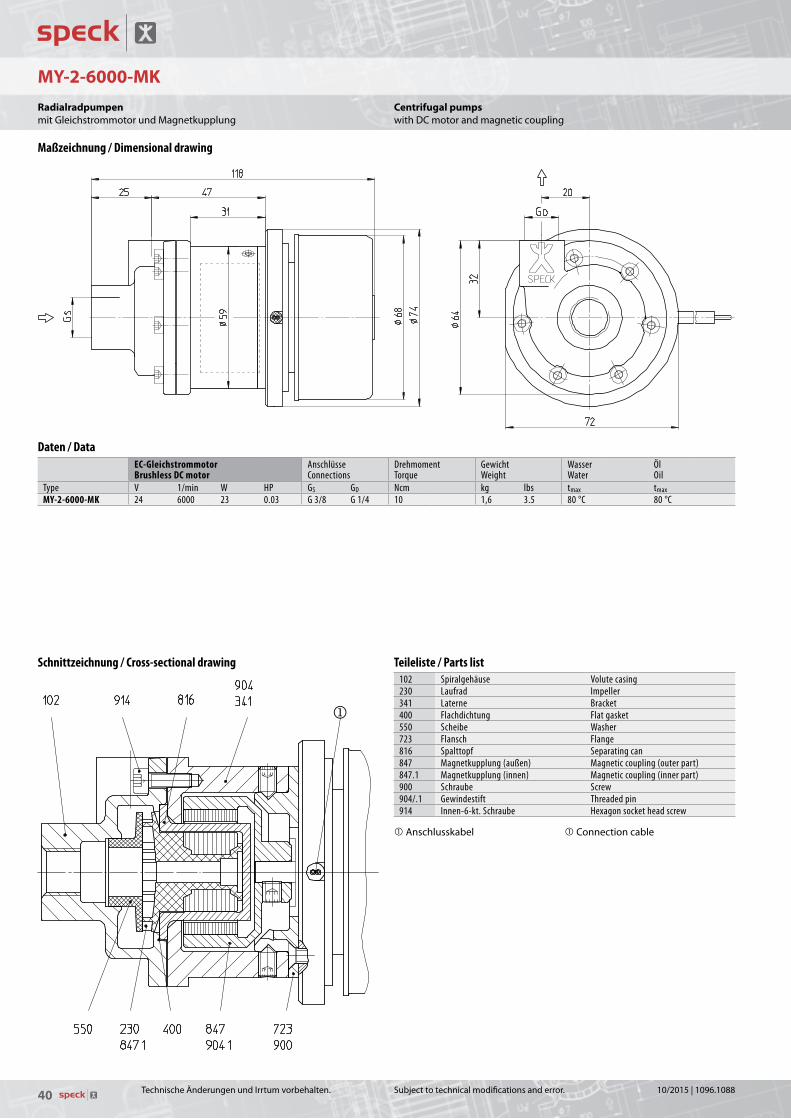
40
MY-2-6000-MK
Subjecttotechnicalmodificationsanderror.
Centrifugal pumpswithDCmotorandmagneticcoupling
Maßzeichnung / Dimensional drawing
Schnittzeichnung / Cross-sectional drawing
Daten / DataEC-GleichstrommotorBrushless DC motor
AnschlüsseConnections
DrehmomentTorque
GewichtWeight
WasserWater
ÖlOil
Type V 1/min W HP GS GD Ncm kg lbs tmax tmaxMY-2-6000-MK 24 6000 23 0.03 G 3/8 G 1/4 10 1,6 3.5 80 °C 80 °C
Teileliste / Parts list102 Spiralgehäuse Volute casing230 Laufrad Impeller341 Laterne Bracket400 Flachdichtung Flat gasket550 Scheibe Washer723 Flansch Flange816 Spalttopf Separating can847 Magnetkupplung (außen) Magnetic coupling (outer part)847.1 Magnetkupplung (innen) Magnetic coupling (inner part)900 Schraube Screw904/.1 Gewindestift Threaded pin914 Innen-6-kt. Schraube Hexagon socket head screw
Anschlusskabel Connectioncable
TechnischeÄnderungenundIrrtumvorbehalten.
RadialradpumpenmitGleichstrommotorundMagnetkupplung
10/2015|1096.1088

41
MY-2-6000-MK
MY-6000-MK
KL 8.50.040
Leis
tung
sbed
arf
Puis
sanc
e ab
sorb
ée
Förderstrom / Débit Q [l/min]
Capacity Q [U.S.GPM] Fö
rder
höhe
H
aute
ur m
anom
étriq
ue
Tota
l hea
d Po
wer
con
sum
ptio
n
H [m]
P [W]
P [HP]
H [feet]
10
9
8
7
6
5
4
3
2
1
0
30
25
20
15
10
5
0 0 2 4 6 8 10 12 14 16 18 20 22
0.04
0.03
0.02
0.01
0
30
25
20
15
10
5
0
0 0.5 1.0 1.5 2.0 2.5 3.0 3.5 4.0 4.5 5.0 5.5
6000 1/min - rpm - tr/min 60001/min-rpm
Subjecttotechnicalmodificationsanderror.
Test conditionsThecharacteristiccurvesareapplicableforthedeliveryofwaterof20°Ctemperatureatnominalspeed.
Thetoleranceoftotalheadandcapacityis±10%,performancetoleranceis+10%.
Ifthepropertyofthepumpmediadiffersthecharacteristiccurveschange.
H[feet]
Tota
lhea
d
P[HP]
Pow
erc
onsu
mpt
ion
Capacity Q [U.S.GPM]
Centrifugal pumpswithDCmotorandmagneticcoupling
Kennlinien / Characteristic curves
Werkstoffausführungen / Material Design
SpiralgehäuseVolute casing
1.4851CrNiMo-cast steel
LaufradImpeller PPS
FlachdichtungFlat gasket Centellen®
SpalttopfSeparating can SiC
TechnischeÄnderungenundIrrtumvorbehalten.
PrüfbedingungenDieKennliniengeltenfürdieFörderungvonWassermiteinerTemperaturvon20°CbeiNenndrehzahl.
DieToleranzvonFörderhöheundFörderstrombeträgt±10%,diedesLeistungsbedarfs+10%.BeiabweichendenEigenschaftendesFördermediumsändernsichdieKennlinien.
P[W]
Leis
tung
sbed
arf
H[m]
Förd
erhö
he
Förderstrom Q [l/min]
RadialradpumpenmitGleichstrommotorundMagnetkupplung
10/2015|1096.1088

42
MY-2-8000-MK
Subjecttotechnicalmodificationsanderror.
Centrifugal pumpswithDCmotorandmagneticcoupling
Maßzeichnung / Dimensional drawing
Schnittzeichnung / Cross-sectional drawing
Daten / DataEC-GleichstrommotorBrushless DC motor
AnschlüsseConnections
DrehmomentTorque
GewichtWeight
WasserWater
ÖlOil
Type V 1/min W HP GS GD Ncm kg lbs tmax tmaxMY-2-6000-MK 24 9000 80 0.11 G 3/8 G 1/4 13 1,3 2.9 80 °C 80 °C
Teileliste / Parts list102 Spiralgehäuse Volute casing230 Laufrad Impeller341 Laterne Bracket400 Flachdichtung Flat gasket550-.3 Scheibe Washer816 Spalttopf Separating can847 Magnetkupplung (außen) Magnetic coupling (outer part)847.1 Magnetkupplung (innen) Magnetic coupling (inner part)904 Gewindestift Threaded pin914/.1 Innen-6-kt. Schraube Hexagon socket head screw931 Sicherungsblech Locking washer
TechnischeÄnderungenundIrrtumvorbehalten.
RadialradpumpenmitGleichstrommotorundMagnetkupplung
10/2015|1096.1088

43
MY-2-8000-MK
MY2-8000-MK
KL 8.50.045
Leis
tung
sbed
arf
Puis
sanc
e ab
sorb
ée
Förderstrom / Débit Q [l/min]
Capacity Q [U.S.GPM] Fö
rder
höhe
H
aute
ur m
anom
étriq
ue
Tota
l hea
d Po
wer
con
sum
ptio
n
H [m]
P [W]
P [HP]
H [feet]
16
14
12
10
8
6
4
2
0
80
60
40
20
0 0 5 10 15 20 25 30
0.10
0.08
0.06
0.04
0.02
0
50
40
30
20
10
0
0 1 2 3 4 5 6 7
9000 1/min - rpm - tr/min 90001/min-rpm
Subjecttotechnicalmodificationsanderror.
Test conditionsThecharacteristiccurvesareapplicableforthedeliveryofwaterof20°Ctemperatureatnominalspeed.
Thetoleranceoftotalheadandcapacityis±10%,performancetoleranceis+10%.
Ifthepropertyofthepumpmediadiffersthecharacteristiccurveschange.
H[feet]
Tota
lhea
d
P[HP]
Pow
erc
onsu
mpt
ion
Capacity Q [U.S.GPM]
Centrifugal pumpswithDCmotorandmagneticcoupling
Kennlinien / Characteristic curves
Werkstoffausführungen / Material Design
SpiralgehäuseVolute casing
1.4851CrNiMo-cast steel
LaufradImpeller PPS
FlachdichtungFlat gasket Centellen®
SpalttopfSeparating can SiC
TechnischeÄnderungenundIrrtumvorbehalten.
PrüfbedingungenDieKennliniengeltenfürdieFörderungvonWassermiteinerTemperaturvon20°CbeiNenndrehzahl.
DieToleranzvonFörderhöheundFörderstrombeträgt±10%,diedesLeistungsbedarfs+10%.BeiabweichendenEigenschaftendesFördermediumsändernsichdieKennlinien.
P[W]
Leis
tung
sbed
arf
H[m]
Förd
erhö
he
Förderstrom Q [l/min]
RadialradpumpenmitGleichstrommotorundMagnetkupplung
10/2015|1096.1088

44
DS-120 / ... / 450-MK
Subjecttotechnicalmodificationsanderror.
Roller vane pumpswithmagneticcoupling,self-priming
Maßzeichnung / Dimensional drawing
Schnittzeichnung / Cross-sectional drawing
Daten / DataBaugrößeFrame size
PhasenPhases 50 Hz / Cycles 60 Hz / Cycles Anschlüsse
ConnectionsDrehmomentTorque
GewichtWeight
WasserWater
Type mm ~ 1/min kW HP 1/min kW HP GS GD Nm kg lbs tmaxDS-120 / ... / 450-MK 63 1 / 3~ 2800 0,3 0.4 3400 0,3 0.4 G 3/8 G 3/8 0,7 6 13.2 70 °C
Teileliste / Parts list101 Gehäuse Casing110 Mittelkörper Stage casing137/.1 Steuerscheibe Inter casing161 Gehäusedeckel Casing cover200 Läufer Rotor238 Laufradschieber Vane341 Laterne Bracket411 Dichtring Sealing ring412-.2 O-Ring O-ring500 Ring Ring560/.1 Stift Pin753 Ventilkegel Valve cone816 Spalttopf Separating can847 Magnetkupplung (außen) Magnetic coupling (outer part)847.1 Magnetkupplung (innen) Magnetic coupling (inner part)904/.1 Gewindestift Threaded pin909 Einstellschraube Adjusting screw914 Innen-6-kt. Schraube Hexagon socket head screw920 6-kt. Mutter Hexagon nut932-.2 Sicherungsring Locking ring940 Passfeder Fitting key950 Druckfeder Pressure spring
GewichtabhängigvonBaugröße,Leistung,WerkstoffenundAusführung
Weightdependingonmotorframesize,performance,materialsandexecution
TechnischeÄnderungenundIrrtumvorbehalten.
DrehschieberpumpenmitMagnetkupplung,selbstansaugend
10/2015|1096.1088

45
DS-120 / ... / 450-MK
50Hz-cycles|28001/min-rpm 60Hz-cycles|34001/min-rpm
DS-120-450-MK KL 4.02.022 KL 4.02.023
Förderstrom / Débit Q [l/min]
Capacity Q [U.S.GPM]
Dru
ck
Pres
sion
Pres
sure
p [bar]
Dru
ck
Pres
sion
p [bar]
p [PSI]
Pres
sure
p [PSI]
14
12
10
8
6
4
2
0
14
12
10
8
6
4
2
0
0 0,5 1,0 1,5 2,0 2,5 3,0 3,5 4,0 4,5 5,0 5,5 6,0 6,5 7,0 7,5 8,0 8,5 9,0 9,5 10
0 0.2 0.4 0.6 0.8 1.0 1.2 1.4 1.6 1.8 2.0 2.2 2.4 2.6 200
180
160
140
120
100
80
60
40
20
0
50 Hz - cycles | 2800 1/min - rpm - tr/min 60 Hz - cycles | 3400 1/min - rpm - tr/min
120-MK 240-MK 360-MK 450-MK
120-MK 240-MK 360-MK 450-MK
Subjecttotechnicalmodificationsanderror.
Capacity Q [U.S.GPM]
Test conditionsThecharacteristiccurvesareapplicableforthedeliveryofwaterof20°Ctemperatureatnominalspeed.
Thetoleranceoftotalheadandcapacityis±10%,performancetoleranceis+10%.
Ifthepropertyofthepumpmediadiffersthecharacteristiccurveschange.
p[psi]
Pres
sure
p[psi]
Pres
sure
Roller vane pumpswithmagneticcoupling,self-priming
50 Hz | Kennlinien / Characteristic curves 60 Hz | Kennlinien / Characteristic curves
Werkstoffausführungen / Material Design
GehäuseCasing
1.4305CrNi-steel
CuZnBrass
SteuerscheibeInter casing
KohleCarbon
MittelkörperStage casing
KohleCarbon
LäuferRotor
1.4301CrNi-steel
WelleShaft
1.4305CrNi-steel
SpalttopfSeparating can
1.4301CrNi-steel
TechnischeÄnderungenundIrrtumvorbehalten.
Förderstrom Q [l/min]
PrüfbedingungenDieKennliniengeltenfürdieFörderungvonWassermiteinerTemperaturvon20°CbeiNenndrehzahl.
DieToleranzvonFörderhöheundFörderstrombeträgt±10%,diedesLeistungsbedarfs+10%.BeiabweichendenEigenschaftendesFördermediumsändernsichdieKennlinien.
p[bar]
Dru
ck
p[bar]
Dru
ck
DrehschieberpumpenmitMagnetkupplung,selbstansaugend
10/2015|1096.1088
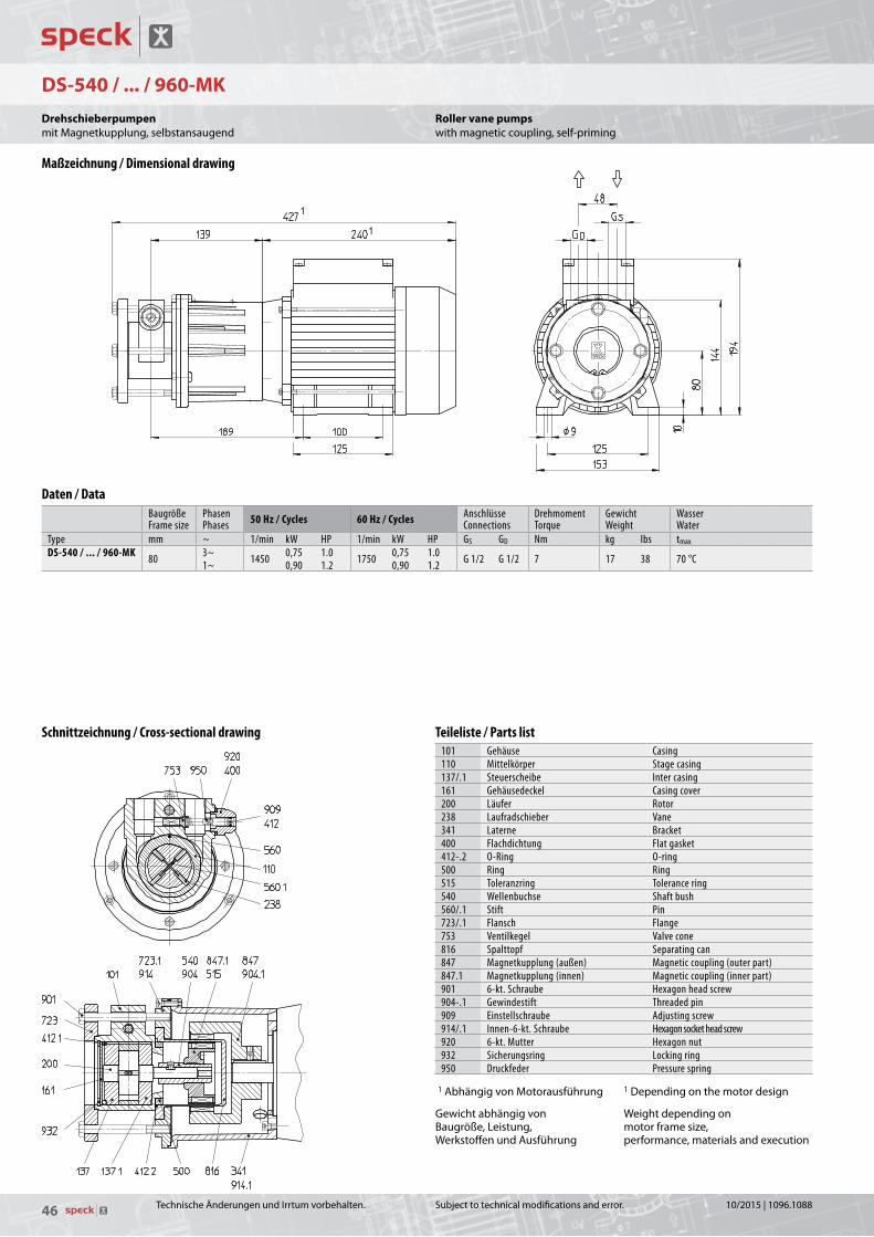
46
DS-540 / ... / 960-MK
1
1
Subjecttotechnicalmodificationsanderror.
Roller vane pumpswithmagneticcoupling,self-priming
Maßzeichnung / Dimensional drawing
Schnittzeichnung / Cross-sectional drawing
Daten / DataBaugrößeFrame size
PhasenPhases 50 Hz / Cycles 60 Hz / Cycles Anschlüsse
ConnectionsDrehmomentTorque
GewichtWeight
WasserWater
Type mm ~ 1/min kW HP 1/min kW HP GS GD Nm kg lbs tmax
DS-540 / ... / 960-MK 80 3~ 1450 0,75 1.0 1750 0,75 1.0 G 1/2 G 1/2 7 17 38 70 °C1~ 0,90 1.2 0,90 1.2
Teileliste / Parts list101 Gehäuse Casing110 Mittelkörper Stage casing137/.1 Steuerscheibe Inter casing161 Gehäusedeckel Casing cover200 Läufer Rotor238 Laufradschieber Vane341 Laterne Bracket400 Flachdichtung Flat gasket412-.2 O-Ring O-ring500 Ring Ring515 Toleranzring Tolerance ring540 Wellenbuchse Shaft bush 560/.1 Stift Pin723/.1 Flansch Flange753 Ventilkegel Valve cone816 Spalttopf Separating can847 Magnetkupplung (außen) Magnetic coupling (outer part)847.1 Magnetkupplung (innen) Magnetic coupling (inner part)901 6-kt. Schraube Hexagon head screw904-.1 Gewindestift Threaded pin909 Einstellschraube Adjusting screw914/.1 Innen-6-kt. Schraube Hexagon socket head screw920 6-kt. Mutter Hexagon nut932 Sicherungsring Locking ring950 Druckfeder Pressure spring
1AbhängigvonMotorausführung
GewichtabhängigvonBaugröße,Leistung,WerkstoffenundAusführung
1Dependingonthemotordesign
Weightdependingonmotorframesize,performance,materialsandexecution
TechnischeÄnderungenundIrrtumvorbehalten.
DrehschieberpumpenmitMagnetkupplung,selbstansaugend
10/2015|1096.1088

47
DS-540 / ... / 960-MK
50Hz-cycles|14501/min-rpm 60Hz-cycles|17501/min-rpm
DS-60 - 960 KL 4.02.019 KL 4.02.020
Förderstrom / Débit Q [l/min]
Capacity Q [U.S.GPM]
Dru
ck
Pres
sion
Pres
sure
p [bar]
Dru
ck
Pres
sion
p [bar]
p [PSI]
Pres
sure
p [PSI]
14
12
10
8
6
4
2
0
14
12
10
8
6
4
2
0
0 1 2 3 4 5 6 7 8 9 10 11 12 13 14 15 16 17 18 19 20
0 0.3 0.6 0.9 1.2 1.5 1.8 2.1 2.4 2.7 3.0 3.3 3.6 3.9 4.2 4.5 4.8 5.1
200
180
160
140
120
100
80
60
40
20
0
200
180
160
140
120
100
80
60
40
20
0
50 Hz - cycles | 1450 1/min - rpm - tr/min 60 Hz - cycles | 1750 1/min - rpm - tr/min
960-MK 720-MK 600-MK 540-MK
960-MK 720-MK 600-MK 540-MK
Subjecttotechnicalmodificationsanderror.
Capacity Q [U.S.GPM]
Test conditionsThecharacteristiccurvesareapplicableforthedeliveryofwaterof20°Ctemperatureatnominalspeed.
Thetoleranceoftotalheadandcapacityis±10%,performancetoleranceis+10%.
Ifthepropertyofthepumpmediadiffersthecharacteristiccurveschange.
p[psi]
Pres
sure
p[psi]
Pres
sure
Roller vane pumpswithmagneticcoupling,self-priming
50 Hz | Kennlinien / Characteristic curves 60 Hz | Kennlinien / Characteristic curves
Werkstoffausführungen / Material Design
GehäuseCasing
1.4305CrNi-steel
SteuerscheibeInter casing
KohleCarbon
MittelkörperStage casing
KohleCarbon
LäuferRotor
1.4301CrNi-steel
WelleShaft
1.4305CrNi-steel
SpalttopfSeparating can
1.4301CrNi-steel
TechnischeÄnderungenundIrrtumvorbehalten.
Förderstrom Q [l/min]
PrüfbedingungenDieKennliniengeltenfürdieFörderungvonWassermiteinerTemperaturvon20°CbeiNenndrehzahl.
DieToleranzvonFörderhöheundFörderstrombeträgt±10%,diedesLeistungsbedarfs+10%.BeiabweichendenEigenschaftendesFördermediumsändernsichdieKennlinien.
p[bar]
Dru
ck
p[bar]
Dru
ck
DrehschieberpumpenmitMagnetkupplung,selbstansaugend
10/2015|1096.1088

48
ZY-3-MM
90
84
7
106
50 G 1/4
G 1/4
31,5
70
139
8 8
84
Ø 88
87,5
Subjecttotechnicalmodificationsanderror.
Gear pumpswithcannedmotor
Maßzeichnung / Dimensional drawing
Daten / DataEC-GleichstrommotorBrushless DC motor
AnschlüsseConnections
GewichtWeight
Öl und KraftstoffeOil and fuels
Type V 1/min kW HP GS GD kg lbs tmaxZY-3-MM 24 1000 - 4000 0,18 0.24 G 1/4 G 1/4 2,8 6.2 -40 °C ... +80 °C
GewichtabhängigvonAusführung Weightdependingonexecution
TechnischeÄnderungenundIrrtumvorbehalten.
ZahnradpumpemitSpalttopfmotor
10/2015|1096.1088
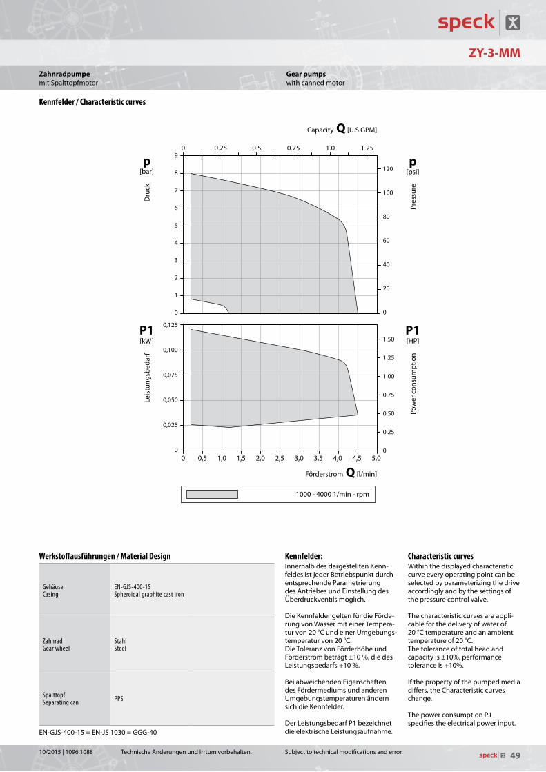
49
ZY-3-MM
Leis
tung
sbed
arf
Puis
sanc
e ab
sorb
ée
Förderstrom / Débit Q [l/min]
Capacity Q [U.S.GPM]
Förd
erdr
uck
Pres
sion
Pres
suer
ePo
wer
con
sum
ptio
n
p[bar]
P[kW]P1
P[HP]P1
p[psi]
9
8
7
6
5
4
3
2
1
0
0 0,5 1,0 1,5 2,0 2,5 3,0 3,5 4,0 4,5 5,0
0,125
0,100
0,075
0,050
0,025
0
0 0.25 0.5 0.75 1.0 1.25
120
100
80
60
40
20
0
1.50
1.25
1.00
0.75
0.50
0.25
0
1000 − 4000 1/min - rpm - tr/min 1000-40001/min-rpm
Subjecttotechnicalmodificationsanderror.
p[psi]
Pres
sure
P1[HP]
Pow
erc
onsu
mpt
ion
Capacity Q [U.S.GPM]
Characteristic curvesWithinthedisplayedcharacteristiccurveeveryoperatingpointcanbeselectedbyparameterizingthedriveaccordinglyandbythesettingsofthepressurecontrolvalve.Thecharacteristiccurvesareappli-cableforthedeliveryofwaterof20°Ctemperatureandanambienttemperatureof20°C.Thetoleranceoftotalheadandcapacityis±10%,performancetoleranceis+10%.
Ifthepropertyofthepumpedmediadiffers,theCharacteristiccurveschange.
ThepowerconsumptionP1specifiestheelectricalpowerinput.
Gear pumpswithcannedmotor
Kennfelder / Characteristic curves
Werkstoffausführungen / Material Design
GehäuseCasing
EN-GJS-400-15 Spheroidal graphite cast iron
ZahnradGear wheel
StahlSteel
SpalttopfSeparating can PPS
EN-GJS-400-15=EN-JS1030=GGG-40
TechnischeÄnderungenundIrrtumvorbehalten.
P1[kW]
Leis
tung
sbed
arf
p[bar]
Dru
ck
Kennfelder:InnerhalbdesdargestelltenKenn-feldesistjederBetriebspunktdurchentsprechendeParametrierungdesAntriebesundEinstellungdesÜberdruckventilsmöglich.
DieKennfeldergeltenfürdieFörde-rungvonWassermiteinerTempera-turvon20°CundeinerUmgebungs-temperaturvon20°C.DieToleranzvonFörderhöheundFörderstrombeträgt±10%,diedesLeistungsbedarfs+10%.
BeiabweichendenEigenschaftendesFördermediumsundanderenUmgebungstemperaturenändernsichdieKennfelder.
DerLeistungsbedarfP1bezeichnetdieelektrischeLeistungsaufnahme.
Förderstrom Q [l/min]
ZahnradpumpemitSpalttopfmotor
10/2015|1096.1088

50
ZY-1 / 2 / 3-MK
50,5
168
L
56Ø
40Ø 32
Ø
36 62
8 62
5
G
7
90
106
17,517,5
1/8
G6
56
145
1/8
Subjecttotechnicalmodificationsanderror.
Gear pumpswithmagneticcoupling,multi-stage,self-priming
Daten / DataBaugrößeFrame size
PhasenPhases 50 Hz / Cycles 60 Hz / Cycles Anschlüsse
ConnectionsDrehmomentTorque
GewichtWeight
Öl und KraftstoffeOil and fuels
Type mm ~ 1/min kW HP 1/min kW HP GS GD Ncm kg lbs tmax
ZY-1-MK1 / 3~ 2800 3400 G 1/8 G 1/8
3,50 7.7-20 °C ... +80 °CZY-2-MK 56 0,12 0.16 0,12 0.16 13 3,75 8.3
ZY-3-MK 4,00 8.8
Type Baugröße LZY-1-MK 255ZY-2-MK 56 260ZY-3-MK 264
Teileliste / Parts list101/.1 Gehäuse Casing161 Gehäusedeckel Casing cover230/.1 Zahnrad Gear wheel341 Laterne Bracket400/.1 Flachdichtung Flat gasket550 Scheibe Washer816 Spalttopf Separating can847 Magnetkupplung (außen) Magnetic coupling (outer part)847.1 Magnetkupplung (innen) Magnetic coupling (inner part)904 Gewindestift Threaded pin914.-3 Innen-6kt. Schraube Hexagon socket head screw
Maßzeichnung / Dimensional drawing
Schnittzeichnung / Cross-sectional drawing
TechnischeÄnderungenundIrrtumvorbehalten.
ZahnradpumpemitMagnetkupplung,mehrstufig,selbstansaugend
10/2015|1096.1088
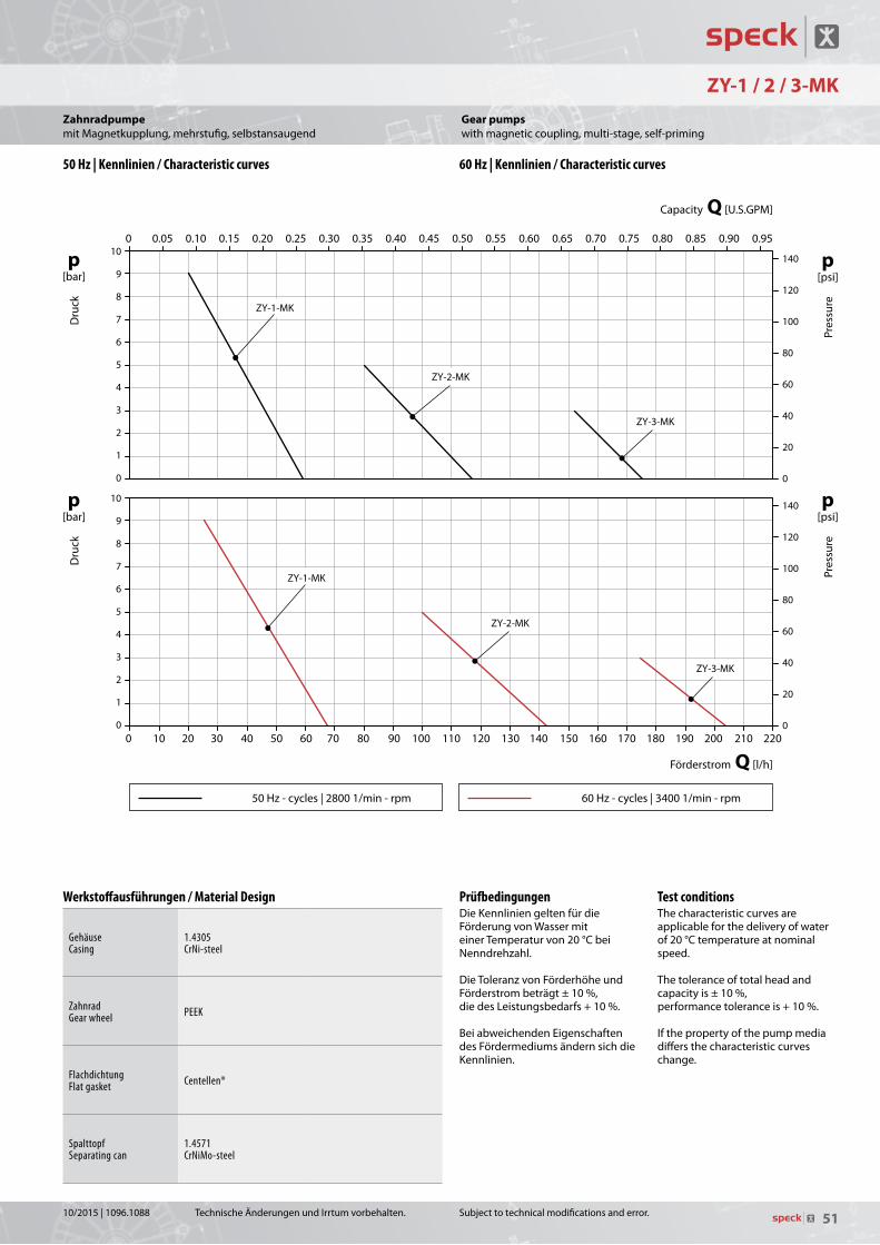
51
ZY-1/2/3-MK KL 4.03.004 KL 4.03.005
Förderstrom / Débit Q [l/h]
Capacity Q [U.S.GPM]
Dru
ck
Pres
sion
Pres
sure
p [bar]
Dru
ck
Pres
sion
p [bar]
p [PSI]
Pres
sure
p [PSI]
10
9
8
7
6
5
4
3
2
1
0
10
9
8
7
6
5
4
3
2
1
0
0 10 20 30 40 50 60 70 80 90 100 110 120 130 140 150 160 170 180 190 200 210 220
0 0.05 0.10 0.15 0.20 0.25 0.30 0.35 0.40 0.45 0.50 0.55 0.60 0.65 0.70 0.75 0.80 0.85 0.90 0.95
140
120
100
80
60
40
20
0
140
120
100
80
60
40
20
0
50 Hz - cycles | 2800 1/min - rpm - tr/min 60 Hz - cycles | 3400 1/min - rpm - tr/min
ZY-1-MK
ZY-2-MK
ZY-3-MK
ZY-1-MK
ZY-2-MK
ZY-3-MK
50Hz-cycles|28001/min-rpm 60Hz-cycles|34001/min-rpm
ZY-1 / 2 / 3-MK
Subjecttotechnicalmodificationsanderror.
Capacity Q [U.S.GPM]
Test conditionsThecharacteristiccurvesareapplicableforthedeliveryofwaterof20°Ctemperatureatnominalspeed.
Thetoleranceoftotalheadandcapacityis±10%,performancetoleranceis+10%.
Ifthepropertyofthepumpmediadiffersthecharacteristiccurveschange.
p[psi]
Pres
sure
p[psi]
Pres
sure
Gear pumpswithmagneticcoupling,multi-stage,self-priming
50 Hz | Kennlinien / Characteristic curves 60 Hz | Kennlinien / Characteristic curves
Werkstoffausführungen / Material Design
GehäuseCasing
1.4305CrNi-steel
ZahnradGear wheel PEEK
FlachdichtungFlat gasket Centellen®
SpalttopfSeparating can
1.4571CrNiMo-steel
TechnischeÄnderungenundIrrtumvorbehalten.
Förderstrom Q [l/h]
PrüfbedingungenDieKennliniengeltenfürdieFörderungvonWassermiteinerTemperaturvon20°CbeiNenndrehzahl.
DieToleranzvonFörderhöheundFörderstrombeträgt±10%,diedesLeistungsbedarfs+10%.BeiabweichendenEigenschaftendesFördermediumsändernsichdieKennlinien.
p[bar]
Dru
ck
p[bar]
Dru
ck
ZahnradpumpemitMagnetkupplung,mehrstufig,selbstansaugend
10/2015|1096.1088

52 Subjecttotechnicalmodificationsanderror.TechnischeÄnderungenundIrrtumvorbehalten. 10/2015|1096.1088

53Subjecttotechnicalmodificationsanderror.TechnischeÄnderungenundIrrtumvorbehalten.10/2015|1096.1088
54 Subjecttotechnicalmodificationsanderror.
Physical-technical units
Liquid pumpsQ Capacity m3/h à U.S.GPM x 4,4029
l/min à U.S.GPM x 0,2642l/h à U.S.GPM x 0,0044U.S.GPM à m3/h x 0,2271U.S.GPM à l/min x 3,7854U.S.GPM à l/h x 227,13
p Pressure bar à psi x 14,504psi à bar x 0,0690
Vacuum pumpsQ Suction capacity m3/h à CFM x 0,5886
CFM à m3/h x 1,6990
p Inlet pressure mbar à inch Hg a x 0,0295inch Hg a à mbar x 33,863
All PumpsH Total Head m à feet x 3,2808
feet à m x 0,3048
P Power kW à HP x 1,3410W à HP x 0,0013HP à kW x 0,7457HP à W x 745,70
Weight kg à lbs x 2,2046lbs à kg x 0,4536
Length mm à inch x 0,0393inch à mm x 25,400
Production Range
Regenerative Turbine Pumps• SmallPumps• HeatTransferPumps• VerticalPumps
Centrifugal Pumps • SmallPumps• HeatTransferPumps• BoilerFeedPumps
Side Channel Pumps • Pumps-StandardEN734• WithNPSH-suctionstage• SmallPumps
Displacement Pumps • RollerVanePumps• GearPumps• OscillatingPistonPumps
Liquid Ring Vacuum Pumps• ClosedCoupledVersion• BasePlateVersion• Vacuumunits
TechnischeÄnderungenundIrrtumvorbehalten.
Produktprogramm
Physikalisch-technische Einheiten
FlüssigkeitspumpenQ Förderstrom m3/h à U.S.GPM x 4,4029
l/min à U.S.GPM x 0,2642l/h à U.S.GPM x 0,0044U.S.GPM à m3/h x 0,2271U.S.GPM à l/min x 3,7854U.S.GPM à l/h x 227,13
p Druck bar à psi x 14,504psi à bar x 0,0690
VakuumpumpenQ Saugvermögen m3/h à CFM x 0,5886
CFM à m3/h x 1,6990
p Ansaugdruck mbar à inch Hg a x 0,0295inch Hg a à mbar x 33,863
Alle PumpenH Förderhöhe m à feet x 3,2808
feet à m x 0,3048
P Leistung kW à HP x 1,3410W à HP x 0,0013HP à kW x 0,7457HP à W x 745,70
Gewicht kg à lbs x 2,2046lbs à kg x 0,4536
Länge mm à inch x 0,0393inch à mm x 25,400
Peripheralradpumpen • Kleinpumpen• Wärmeträgerpumpen• Eintauchpumpen
Radialradpumpen • Kleinpumpen• Wärmeträgerpumpen• Kesselspeisepumpen
Seitenkanalpumpen • PumpennachNormEN734• MitNPSH-Vorstufe• Kleinpumpen
Verdrängerpumpen• Drehschieberpumpen• Zahnradpumpen• Schwingankerpumpen
Flüssigkeitsring-Vakuumpumpen• Blockbauweise• Grundplattenbauweise• Vakuumanlagen
10/2015|1096.1088
D Produktion / Verwaltung Production / Administration
Speck Pumpen Walter Speck GmbH & Co. KGSpeck Pumpen Systemtechnik GmbHSpeck Pumpen Vakuumtechnik GmbHRegensburger Ring 6 – 8, 91154 Roth
Tel.: +49 9171 809 0Fax: +49 9171 809 10
D Germany
Deutschland OstHuckauf Ingenieure GmbHRathausstraße 509244 LichtenauTel.: +49 37208 660 80Fax: +49 37208 660 [email protected]
BerlinHuckauf Ingenieure GmbHFontanepromenade 1710967 BerlinTel.: +49 30 890 959 92Fax: +49 30 890 959 [email protected]
NorddeutschlandIngenieure Willy Wandrach GmbHFlurstraße 10522549 HamburgTel.: +49 40 398 624 0Fax: +49 40 398 624 [email protected]
Hannover, KasselIVT – Pumpen GmbHZum Wischfeld 1A31749 AuetalTel.: +49 5752 929 597Fax: +49 5752 929 599Mobile: +49 172 511 699 [email protected]
KölnHuckauf Ingenieure GmbHGrillenpfad 2840764 LangenfeldTel.: +49 2173 914 560Fax: +49 2173 914 [email protected]
Bayern, Baden-WürttembergSpeck PumpenVERKAUFSGESELLSCHAFT GmbHHauptstraße 1 – 391233 Neunkirchen a. SandTel.: +49 9123 949 – 0Fax: +49 9123 949 – [email protected]
Service
Deutschland MitteFSE Fluid Systems ErfurtPoeler Weg 699085 ErfurtTel.: +49 361 550 715 0Fax: +49 361 550 715 [email protected]
KölnArpuma GmbHOttostrasse 1050170 KerpenTel.: +49 2273 953 300 0Fax: +49 2273 953 300 [email protected]
International
A AustriaTuma Pumpensysteme GmbHEitnergasse 121230 WienTel.: +43 191 493 40Fax.: +43 191 414 [email protected]
AUS AustraliaPump Solutions AustralasiaUnit 17 Bessemer WayWangara, WA 6065P.O. Box 1811Wangara DC, WA 6947Tel.: +61 8 9408 1544Fax: +61 8 9408 [email protected]
Pump Systems AustraliaFactory 221 London DriveBayswater /MelbourneVictoria 3153Tel.: +61 397 623 100Fax: +61 397 623 [email protected]
B BelgiumHeat transfer pumps / Pompes pour fluid thermiqueFLOWMOTION BVBAMergelweg 31730 AsseTel.: +32 2 309 67 13Fax. +32 2 309 69 [email protected]
SPECK - Pompen Belgie N.V.Bierweg 249880 AalterTel.: +32 937 530 39Fax: +32 932 500 [email protected]
BG BulgariaEVROTECH OOD54 A, Manastirska Str.1111 SofiaTel.: +359 2 971 32 73Fax: +359 2 971 22 88 [email protected] CH Switzerland
Speck Pumpen SubsidiarySpeck Pumpen Industrie GmbHBürglenweg 48854 GalgenenTel.: +41 554 425 094Fax: +41 554 425 [email protected]
Sales and ServiceHänyTec AGLättfeld 26142 GettnauTel.: +41 62 544 33 00Fax: +41 62 544 33 [email protected]
ServiceMEYER ARMATUREN PUMPEN GMBHRigackerstrasse 195610 WohlenTel. + 41 56 622 77 33Fax + 41 56 622 77 [email protected]
CN ChinaSpeck Pumpen SubsidiaryJiashan SPECK PUMPSSystemtechnik Ltd. No. 57, Hong Qiao Rd., No. 4 Economical Developing Zone,314100 Jiashan Xian, Zhejiang ProvinceTel.: +86 573 847 312 98Fax: +86 573 847 312 [email protected] www.speck-pumps.cn
CZ Czech RepublicSigmet spol s.r.o.Kosmonautu č.p. 1103/6a77200 OlomoucTel.: +420 585 231 070Fax: +420 585 227 [email protected]
DK DenmarkPumpegruppen a/sLundtoftegårdsvej 952800 LyngbyTel.: +45 459 371 00Fax: +45 459 347 [email protected]
E SpainSpeck Pumpen SubsidiarySPECK BOMBAS INDUSTRIALES, S.L.U.Trafalgar, 53 despacho 6Centro de Negocios CNAF46023 Valencia Tel.: +34 963 811 094Fax: +34 963 811 096Mobile: +34 618 376 [email protected]
F FranceSpeck Pumpen SubsidiarySpeck Pompes Industries S.A.Z.I. Parc d’Activités du Ried4, rue de l’EnergieB.P. 22767727 Hoerdt CedexTel.: +33 3 88 68 26 60Fax: +33 3 88 68 16 [email protected]
GB Great BritainSpeck ABC UK LtdAreenA HouseMoston Road, Elworth, SandbachCheshire CW11 3HLTel.: +44 844 764 063 2Fax: +44 844 764 063 [email protected]
GR GreeceSPECK HellasSalaminos St. 5417676 KallitheaTel.: +30 210 956 500 6Fax: +30 210 957 747 [email protected]
I ItalyCentrifugal pumps / Pompe centrifugheSpeck Industries S.r.l Via Garibaldi, 5320010 Canegrate (MI)Tel.: +39 0331 405 805Mobile: +39 339 16 59 [email protected]
Vacuum pumps / Pompe per vuotoRio Nanta S.r.l.Via Mauro Macchi, 4220124 MilanoTel. +39 028 940 642 1Fax: +39 028 323 913Mobile: +39 339 658 781 [email protected]
IL IsraelAmbi-TechElectronics Engineering Ltd.,20 Ta’as st.;Industrial Area, Kfar-SabaP.O. Box 50Kfar-Saba 44425Tel.: +972 976 775 00Fax: +972 976 774 [email protected]
Small pumps /heat transfer pumps : Ringel Brothers (1973) Ltd.134 Hertzel St.P.O. Box 5148Tel-Aviv 66555Tel.: +972 368 255 05Fax: +972 368 220 41Mobile: +972 544 623 [email protected]
IND IndiaFlux Pumps India Pvt. Ltd.427/A-2, Gultekdi Industrial EstateNear Prabhat Printing PressPune – 411 047, MaharashtraTel.: +91 020 2427 1023Fax: +91 020 2427 0689Mobile: +91 98504 [email protected]
J JapanRodateq, Inc.Suite 301 Oka Bldg.2 - 1 - 16 Kyomachibori, Nishiku550 – 0003 OsakaTel.: +81 664 441 940Fax: +81 664 449 [email protected]
Rodateq, Inc.Tokyo BranchNo. 408, 3 - 22 - 12Highashi Ikebukuro, Toshima - ku170-0013 TokyoTel.: +81 359 798 818Fax: +81 359 798 [email protected]
L LuxembourgHeat transfer pumps / Pompes pour fluid thermiqueFLOWMOTION BVBAMergelweg 31730 AsseTel.: +32 2 309 67 13Fax. +32 2 309 69 [email protected]
MAL MalaysiaLeesonmechEngineering ( M ) Sdn. Bhd.No. 18 Jalan 18, Taman Sri Kluang,86000 Kluang, JohorTel.: +607 777 105 5Fax: +607 777 106 [email protected]
N NorwayIng. Per Gjerdrum A/SP.O. Box 154Nye Vakasvei 281360 NesbruTel.: +47 667 756 00Fax: +47 667 756 [email protected]
NL NetherlandsCentrifugal pumps / CentrifugaalpompenSpeck Pompen Nederland B.V.Businesspark 7PoortStationspoort 106902 KG ZevenaarTel.: +31 316 331 757Fax: +31 316 528 [email protected] www.speck.nl
Vacuum pumps / VacuümpompenDOVAC B.V.Meer en Duin 2282163 HD LisseTel.: +31 252 423 363Fax: +31 252 417 [email protected]
Heat transfer pumps / Pompes pour fluid thermiqueFLOWMOTION BVBAMergelweg 31730 AsseTel.: +32 2 309 67 13Fax. +32 2 309 69 [email protected]
NZ New ZealandMacEwans Pumping Systems Ltd.19 Ride WayNorth Harbour Industrial EstateTel.: +64 941 548 60Fax: +64 941 548 [email protected]
P PortugalUltra ControloProjectos Industriais, Lda.Quinta Lavi – Armazém 8Abrunheira27 10 - 089 SintraTel.: +351 219 154 350Fax: +351 219 259 [email protected]
PL PolandE.A. Krupinski Elzbieta Krupinskaul. Przymiarki 4A31-764 KrakowTel. / Fax: +48 126 455 [email protected]
RC TaiwanSpeck Pumpen SubsidiarySpeck Pumps Technology Taiwan Ltd.2Fl., no. 153, Sec. 2Datong Rd., Xizhi DistrictNew Taipei CityTel.: +886 286 926 220Fax: +886 286 926 759Mobile: +886 936 120 [email protected]
RCH ChileW & F Ingenieria Y Maquinas S.A.Felix de Amesti 90, Piso 6Las Condes, SantiagoTel.: +56 220 629 43Fax: +56 220 630 [email protected]
RI IndonesiaPT Roda Rollen IndonesiaKompleks Pertokoan Glodok Jaya No. 30Jl. Hayam Wuruk,Jakarta - PusatIndonesia, 11180Tel.: +6221 659 922 528Fax: +6221 380 595 [email protected]
ROK CoreaJ.C. International Inc.2F, Bikeum Bldg. 108,Yanghwa-Ro, Mapo-Gu,121-893 SeoulTel.: +82 232 628 00Fax: +82 232 569 [email protected]
RO RomaniaS.C. Gimsid S.R.L.Str. Arcului nr. 9, Arp.2021031 BucurestiTel.: +40 21 2118701Fax: +40 21 [email protected]
RUS RussiaLLC Firm KreolineYunosti str., 5/3Moscow 111395Tel.: +7 495 737 321 4Fax: +7 495 769 844 0Mobile: +7 495 505 198 [email protected]
S SwedenHugo Tillquist ABP.O.Box 112016422 Kista Tel.: +46 859 463 200Fax: +46 875 136 [email protected]
SK Slovakian Republic Czech Republic (CZ)
SLO SloveniaSLOTEH Branko Gabric s.p.Zagrebška cesta 202000 MariborTel.: +38 624 614 460Fax: +38 624 614 [email protected]
SGP Singapore Malaysia (MAL)
T ThailandSpeck Pumpen SubsidiaryPump Systems Flux & Speck Co. Ltd.181/4 Soi AnamaiSrinakarin RoadSuanluang Bangkok 10250Tel.: +662 320 256 7Fax: +662 322 248 [email protected]
TR TurkeySpeck PompaSan. ve Tic. Ltd. Sti.Girne Mah., Kücükyali Is Merkezi B Blok No.12 Maltepe34852 IstanbulTel.: +90 216 375 750 5Fax: +90 216 375 753 3Mobil: +(90) 532 293 010 [email protected]
USA USASpeck Pumpen SubsidiarySpeck Industries LP301 Veterans BlvdRutherfordNJ 07070Tel.: +1 201 569 3114Fax: +1 201 569 [email protected]
ZA Rep. South AfricaAQUAPUMP ( Pty ) Ltd.Unit 54APD Industrial parkKelvin streetKya SandTel.: +27 117 080 600Fax: +27 865 864 151Mobile: +27 824 509 [email protected]
09_1
5
55
Ausgabeedition
10/2015ErsatzfürAusgabe
replacesedition02/2015
Representations
D Produktion / Verwaltung Production / Administration
Speck Pumpen Walter Speck GmbH & Co. KGSpeck Pumpen Systemtechnik GmbHSpeck Pumpen Vakuumtechnik GmbHRegensburger Ring 6 – 8, 91154 Roth
Tel.: +49 9171 809 0Fax: +49 9171 809 10
D Germany
Deutschland OstHuckauf Ingenieure GmbHRathausstraße 509244 LichtenauTel.: +49 37208 660 80Fax: +49 37208 660 [email protected]
BerlinHuckauf Ingenieure GmbHFontanepromenade 1710967 BerlinTel.: +49 30 890 959 92Fax: +49 30 890 959 [email protected]
NorddeutschlandIngenieure Willy Wandrach GmbHFlurstraße 10522549 HamburgTel.: +49 40 398 624 0Fax: +49 40 398 624 [email protected]
Hannover, KasselIVT – Pumpen GmbHZum Wischfeld 1A31749 AuetalTel.: +49 5752 929 597Fax: +49 5752 929 599Mobile: +49 172 511 699 [email protected]
KölnHuckauf Ingenieure GmbHGrillenpfad 2840764 LangenfeldTel.: +49 2173 914 560Fax: +49 2173 914 [email protected]
Bayern, Baden-WürttembergSpeck PumpenVERKAUFSGESELLSCHAFT GmbHHauptstraße 1 – 391233 Neunkirchen a. SandTel.: +49 9123 949 – 0Fax: +49 9123 949 – [email protected]
Service
Deutschland MitteFSE Fluid Systems ErfurtPoeler Weg 699085 ErfurtTel.: +49 361 550 715 0Fax: +49 361 550 715 [email protected]
KölnArpuma GmbHOttostrasse 1050170 KerpenTel.: +49 2273 953 300 0Fax: +49 2273 953 300 [email protected]
International
A AustriaTuma Pumpensysteme GmbHEitnergasse 121230 WienTel.: +43 191 493 40Fax.: +43 191 414 [email protected]
AUS AustraliaPump Solutions AustralasiaUnit 17 Bessemer WayWangara, WA 6065P.O. Box 1811Wangara DC, WA 6947Tel.: +61 8 9408 1544Fax: +61 8 9408 [email protected]
Pump Systems AustraliaFactory 221 London DriveBayswater /MelbourneVictoria 3153Tel.: +61 397 623 100Fax: +61 397 623 [email protected]
B BelgiumHeat transfer pumps / Pompes pour fluid thermiqueFLOWMOTION BVBAMergelweg 31730 AsseTel.: +32 2 309 67 13Fax. +32 2 309 69 [email protected]
SPECK - Pompen Belgie N.V.Bierweg 249880 AalterTel.: +32 937 530 39Fax: +32 932 500 [email protected]
BG BulgariaEVROTECH OOD54 A, Manastirska Str.1111 SofiaTel.: +359 2 971 32 73Fax: +359 2 971 22 88 [email protected] CH Switzerland
Speck Pumpen SubsidiarySpeck Pumpen Industrie GmbHBürglenweg 48854 GalgenenTel.: +41 554 425 094Fax: +41 554 425 [email protected]
Sales and ServiceHänyTec AGLättfeld 26142 GettnauTel.: +41 62 544 33 00Fax: +41 62 544 33 [email protected]
ServiceMEYER ARMATUREN PUMPEN GMBHRigackerstrasse 195610 WohlenTel. + 41 56 622 77 33Fax + 41 56 622 77 [email protected]
CN ChinaSpeck Pumpen SubsidiaryJiashan SPECK PUMPSSystemtechnik Ltd. No. 57, Hong Qiao Rd., No. 4 Economical Developing Zone,314100 Jiashan Xian, Zhejiang ProvinceTel.: +86 573 847 312 98Fax: +86 573 847 312 [email protected] www.speck-pumps.cn
CZ Czech RepublicSigmet spol s.r.o.Kosmonautu č.p. 1103/6a77200 OlomoucTel.: +420 585 231 070Fax: +420 585 227 [email protected]
DK DenmarkPumpegruppen a/sLundtoftegårdsvej 952800 LyngbyTel.: +45 459 371 00Fax: +45 459 347 [email protected]
E SpainSpeck Pumpen SubsidiarySPECK BOMBAS INDUSTRIALES, S.L.U.Trafalgar, 53 despacho 6Centro de Negocios CNAF46023 Valencia Tel.: +34 963 811 094Fax: +34 963 811 096Mobile: +34 618 376 [email protected]
F FranceSpeck Pumpen SubsidiarySpeck Pompes Industries S.A.Z.I. Parc d’Activités du Ried4, rue de l’EnergieB.P. 22767727 Hoerdt CedexTel.: +33 3 88 68 26 60Fax: +33 3 88 68 16 [email protected]
GB Great BritainSpeck ABC UK LtdAreenA HouseMoston Road, Elworth, SandbachCheshire CW11 3HLTel.: +44 844 764 063 2Fax: +44 844 764 063 [email protected]
GR GreeceSPECK HellasSalaminos St. 5417676 KallitheaTel.: +30 210 956 500 6Fax: +30 210 957 747 [email protected]
I ItalyCentrifugal pumps / Pompe centrifugheSpeck Industries S.r.l Via Garibaldi, 5320010 Canegrate (MI)Tel.: +39 0331 405 805Mobile: +39 339 16 59 [email protected]
Vacuum pumps / Pompe per vuotoRio Nanta S.r.l.Via Mauro Macchi, 4220124 MilanoTel. +39 028 940 642 1Fax: +39 028 323 913Mobile: +39 339 658 781 [email protected]
IL IsraelAmbi-TechElectronics Engineering Ltd.,20 Ta’as st.;Industrial Area, Kfar-SabaP.O. Box 50Kfar-Saba 44425Tel.: +972 976 775 00Fax: +972 976 774 [email protected]
Small pumps /heat transfer pumps : Ringel Brothers (1973) Ltd.134 Hertzel St.P.O. Box 5148Tel-Aviv 66555Tel.: +972 368 255 05Fax: +972 368 220 41Mobile: +972 544 623 [email protected]
IND IndiaFlux Pumps India Pvt. Ltd.427/A-2, Gultekdi Industrial EstateNear Prabhat Printing PressPune – 411 047, MaharashtraTel.: +91 020 2427 1023Fax: +91 020 2427 0689Mobile: +91 98504 [email protected]
J JapanRodateq, Inc.Suite 301 Oka Bldg.2 - 1 - 16 Kyomachibori, Nishiku550 – 0003 OsakaTel.: +81 664 441 940Fax: +81 664 449 [email protected]
Rodateq, Inc.Tokyo BranchNo. 408, 3 - 22 - 12Highashi Ikebukuro, Toshima - ku170-0013 TokyoTel.: +81 359 798 818Fax: +81 359 798 [email protected]
L LuxembourgHeat transfer pumps / Pompes pour fluid thermiqueFLOWMOTION BVBAMergelweg 31730 AsseTel.: +32 2 309 67 13Fax. +32 2 309 69 [email protected]
MAL MalaysiaLeesonmechEngineering ( M ) Sdn. Bhd.No. 18 Jalan 18, Taman Sri Kluang,86000 Kluang, JohorTel.: +607 777 105 5Fax: +607 777 106 [email protected]
N NorwayIng. Per Gjerdrum A/SP.O. Box 154Nye Vakasvei 281360 NesbruTel.: +47 667 756 00Fax: +47 667 756 [email protected]
NL NetherlandsCentrifugal pumps / CentrifugaalpompenSpeck Pompen Nederland B.V.Businesspark 7PoortStationspoort 106902 KG ZevenaarTel.: +31 316 331 757Fax: +31 316 528 [email protected] www.speck.nl
Vacuum pumps / VacuümpompenDOVAC B.V.Meer en Duin 2282163 HD LisseTel.: +31 252 423 363Fax: +31 252 417 [email protected]
Heat transfer pumps / Pompes pour fluid thermiqueFLOWMOTION BVBAMergelweg 31730 AsseTel.: +32 2 309 67 13Fax. +32 2 309 69 [email protected]
NZ New ZealandMacEwans Pumping Systems Ltd.19 Ride WayNorth Harbour Industrial EstateTel.: +64 941 548 60Fax: +64 941 548 [email protected]
P PortugalUltra ControloProjectos Industriais, Lda.Quinta Lavi – Armazém 8Abrunheira27 10 - 089 SintraTel.: +351 219 154 350Fax: +351 219 259 [email protected]
PL PolandE.A. Krupinski Elzbieta Krupinskaul. Przymiarki 4A31-764 KrakowTel. / Fax: +48 126 455 [email protected]
RC TaiwanSpeck Pumpen SubsidiarySpeck Pumps Technology Taiwan Ltd.2Fl., no. 153, Sec. 2Datong Rd., Xizhi DistrictNew Taipei CityTel.: +886 286 926 220Fax: +886 286 926 759Mobile: +886 936 120 [email protected]
RCH ChileW & F Ingenieria Y Maquinas S.A.Felix de Amesti 90, Piso 6Las Condes, SantiagoTel.: +56 220 629 43Fax: +56 220 630 [email protected]
RI IndonesiaPT Roda Rollen IndonesiaKompleks Pertokoan Glodok Jaya No. 30Jl. Hayam Wuruk,Jakarta - PusatIndonesia, 11180Tel.: +6221 659 922 528Fax: +6221 380 595 [email protected]
ROK CoreaJ.C. International Inc.2F, Bikeum Bldg. 108,Yanghwa-Ro, Mapo-Gu,121-893 SeoulTel.: +82 232 628 00Fax: +82 232 569 [email protected]
RO RomaniaS.C. Gimsid S.R.L.Str. Arcului nr. 9, Arp.2021031 BucurestiTel.: +40 21 2118701Fax: +40 21 [email protected]
RUS RussiaLLC Firm KreolineYunosti str., 5/3Moscow 111395Tel.: +7 495 737 321 4Fax: +7 495 769 844 0Mobile: +7 495 505 198 [email protected]
S SwedenHugo Tillquist ABP.O.Box 112016422 Kista Tel.: +46 859 463 200Fax: +46 875 136 [email protected]
SK Slovakian Republic Czech Republic (CZ)
SLO SloveniaSLOTEH Branko Gabric s.p.Zagrebška cesta 202000 MariborTel.: +38 624 614 460Fax: +38 624 614 [email protected]
SGP Singapore Malaysia (MAL)
T ThailandSpeck Pumpen SubsidiaryPump Systems Flux & Speck Co. Ltd.181/4 Soi AnamaiSrinakarin RoadSuanluang Bangkok 10250Tel.: +662 320 256 7Fax: +662 322 248 [email protected]
TR TurkeySpeck PompaSan. ve Tic. Ltd. Sti.Girne Mah., Kücükyali Is Merkezi B Blok No.12 Maltepe34852 IstanbulTel.: +90 216 375 750 5Fax: +90 216 375 753 3Mobil: +(90) 532 293 010 [email protected]
USA USASpeck Pumpen SubsidiarySpeck Industries LP301 Veterans BlvdRutherfordNJ 07070Tel.: +1 201 569 3114Fax: +1 201 569 [email protected]
ZA Rep. South AfricaAQUAPUMP ( Pty ) Ltd.Unit 54APD Industrial parkKelvin streetKya SandTel.: +27 117 080 600Fax: +27 865 864 151Mobile: +27 824 509 [email protected]
09_1
5

10/2
015
–10
96.1
088
SpeckPumpenSystemtechnikGmbH
Postfach1453·91142Roth/GermanyRegensburgerRing6–8·91154Roth/Germany
Tel.:+499171809-0Fax:+499171809-10