(2) station with the spine wastewater tunnel (swwt)
TRANSCRIPT

JICA PREPARATORY SURVEY ON GREATER CAIRO METRO LINE NO.4
Final Report – Volume 2 4-18
(2) Station with the Spine Wastewater Tunnel (SWWT)
Some stations are planned to be located where the SWWT runs. The station could be
constructed without diverting or relocating the SWWT if suitable method is applied. The
cut and cover method with road decks is applied similar to the standard station. The
SWWT would be hanged with a wire during excavation and construction of the concrete
slab. After the concrete slab is cast, the SWWT is borne by its concrete base on the
concrete slab. The SWWT is put and operated permanently in the station. The practice of
this method in Japan is shown in Figure 4-14 and the procedure for construction is
illustrated in Figure 4-15.
In case the ground around the station is made up of very soft soil, it is realized that the
shear force on the SWWT occurs at the interface between soil and concrete wall of the
station due to the difference of the stiffness around the SWWT when earthquake or similar
incidence happens. As a countermeasure, the space between the SWWT and the concrete
wall is filled with elastic seal and the SWWT is wrapped with a seismic isolation material
such as rubber, foamed polystyrene, etc. The space around the SWWT in the station is
then filled with fluid soil cement which has less drying shrinkage and less permeability. The
outline of the proposed method based on experience and practice in Japan is illustrated in
Figure 4-16.
Source: Kumagai Co., Ltd.
Figure 4-14 Procedure of the Road Deck Method during Station Construction
Sewage Settlement

JICA PREPARATORY SURVEY ON GREATER CAIRO METRO LINE NO.4
Final Report – Volume 2 4-19
(1) R
oad
Dec
king
and
Initi
al E
xcav
atio
n(2
) Con
stru
ctio
n of
Top
Con
cret
e S
lab
(3) P
rote
ctio
n of
Spi
ne W
aste
Wat
er T
unne
l
(4) H
angi
ng o
f Spi
ne W
aste
Wat
er T
unne
l by
Wire
(5) S
uppo
rt o
f Spi
ne W
aste
Wat
er T
unne
l by
Con
cret
eB
ase
and
Con
stru
ctio
n of
Sec
ond
Con
cret
e S
lab
Source: JICA Study Team
Figure 4-15 Procedure of Hanging Spine Wastewater Tunnel in Station Construction

JICA PREPARATORY SURVEY ON GREATER CAIRO METRO LINE NO.4
Final Report – Volume 2 4-20
Source: JICA Study Team
Figure 4-16 Seismic Countermeasure for the SWWT in Station
(3) Station No. 8 under an Existing Railway (Ghamrah)
Station No.8 at Ghamrah is planned to be located under the existing Metro Line 1 and tram.
It is noted however that the viaduct of the highway crosses the intersection. The station
could not be constructed by cut and cover method and thus, it is necessary to apply the
crossing under railway method which will enable passing through the existing railway and
highway. The plan of Station No.8 in Ghamrah station is shown in Figure 4-17.
Spine Waste Water Tunnel
Elastic Seal
Seismic Isolation (Rubber, Foamed Polystyrene etc.)
Filled by Fluid Cement Soil qu=10N/mm2

JICA PREPARATORY SURVEY ON GREATER CAIRO METRO LINE NO.4
Final Report – Volume 2 4-21
North
Portsaid st. SWT
Station No.8Line-4 Phase-2
Line-1 & Tram
Source: JICA Study Team
Figure 4-17 Plan at Station No. 8 (Ghamrah)
There are various methods of crossing under railways. The following two methods could
be adopted:
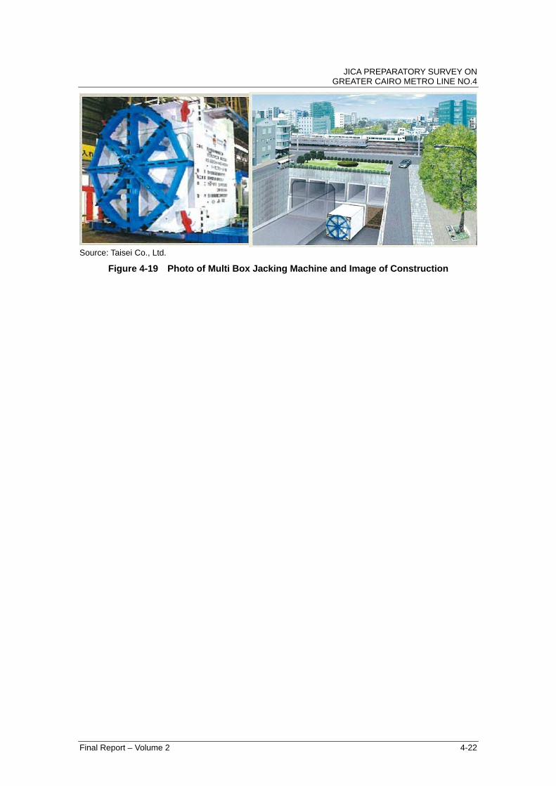
a) Multi Box Jacking Method
A small box shaped called the Earth Pressure Balanced Machine (EPBM)
excavates under the existing railway while steel temporary segments are pushed
by thrust jacking. The EPBM launches from the departure shaft and reaches the
arrival shaft. After that, the EPBM returns to the departure shaft. This
procedure is repeated until temporary box made from small steel boxes is
constructed. The permanent concrete is cast for column, slab and wall, and
temporary steel is then removed. The ground surface settlement is strictly
controlled and the station could be constructed without stopping existing railway
and highway operations.
Source: Taisei Co., Ltd.
Figure 4-18 Image of Station No. 8 (Ghamrah) Constructed Using the Multi Box Jacking
JICA PREPARATORY SURVEY ON GREATER CAIRO METRO LINE NO.4
Final Report – Volume 2 4-22
Source: Taisei Co., Ltd.
Figure 4-19 Photo of Multi Box Jacking Machine and Image of Construction

JICA PREPARATORY SURVEY ON GREATER CAIRO METRO LINE NO.4
Final Report – Volume 2 4-23
b) HEP & JES Method
This method involves drilling of small horizontal bore holes and inserting of steel
wire strand through bore holes. At the end of the bore holes, the traction
equipment is fixed and the drilling equipment and steel structure elements is
pulled using the steel wire strand. Installed small steel structure elements are
connected to each other and combined to act as columns and beams. The steel
structure elements are filled with concrete and could be used as part of the
permanent structure. The station could be constructed without stopping existing
railway and highway operations. However, the ground surface settlement is
relatively large compared with the multi box jacking method, and it is necessary to
study carefully the influence to the existing highway.
Source: Tekken Co., Ltd.
Figure 4-20 Image of Station No. 8 (Ghamrah) constructed Using HEP and JES Method
Source: Tekken Co., Ltd.
Figure 4-21 Photo and Image of HEP and JES Construction Method
Traction Equipment
Steel Strand
Drilling Equipment
Steel Element
Mucking Equipment

JICA PREPARATORY SURVEY ON GREATER CAIRO METRO LINE NO.4
Final Report – Volume 2 4-24
4.4.3 Tunnel Construction Methodology
The city tunnel is usually constructed by cut and cover method or shield TBM. The
alignment of tunnel passes under the road of the residential area and directly below some
part of the dwelling places. Taking into account the influence to the structure and houses at
ground level, the shield TBM is applied for the whole tunnel section. There are foundations
and piles of buildings and flyovers/viaducts. Besides, there is a narrow space for the
tunnels to pass under the existing underpass at road intersections. Therefore, the two
single track tunnels by shield TBMs are selected to pass through shallower area as much
as possible. In addition, the cost for two machines of the single track double tube is
cheaper than one machine for double track tube. Comparing the speed of constructing
the tunnel, the single track double tube tends to be faster because its cutting face has
higher stability (smaller cross section). Thus, the single track double tube is more
advantageous.
Table 4-4 Single Track Double Tube and Double Tracks Tubel
Single Track Double Tube (STDT) Double Track Tube (DTT)
Typical Tunnel Cross Section
Type of Machine Earth Pressure Balanced Shield TBM
Outer Diameter 6.8m x 2 Tube 10.3m
Sectional Area A=72.64m2 A=83.32m2
Overburden Smaller than DTT Larger than STDT
Avoiding of Obstacle Easier (Flexible Location) than DTT More Difficult than STDT
Construction Period Little Bit Faster than DTT Little Bit Slower than STDT
Cost of Machine USD12-14 million for Two Machine USD14-15 million or higher Source: JICA Study Team In order to launch the shield TBM, the construction yard is required and the station where
the shield TBM could launch is limited due to constraints caused by obstructions and land
use. The time schedule of the subway construction is usually dominated and controlled by
the construction of the station, and the schedule of the shield TBM is not critical to pass in
most cases. Therefore, the installation of many shield TBMs is disadvantageous in terms

JICA PREPARATORY SURVEY ON GREATER CAIRO METRO LINE NO.4
Final Report – Volume 2 4-25
of cost. Taking into consideration these conditions, the tunnel construction methodology
for Phase 2 is assumed as follows. The detailed condition need to be studied furthermore.
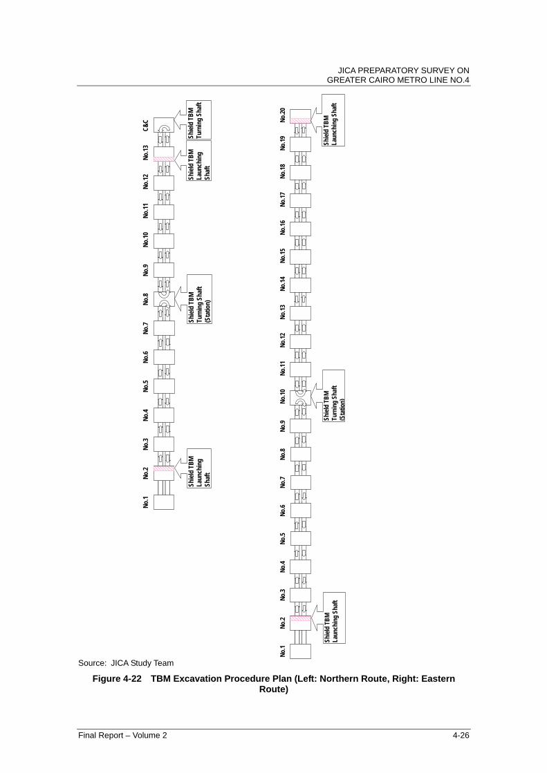
1. Two shield TBMs are installed for each alternative.
2. Shield TBM for single track
3. Station for shield TBM launching (possible station)
Northern Route: Station No. 2 and Station No. 13 Eastern Route: Station No. 2 and Station No. 20
4. Shield TBM would pass through stations under construction.
5. Shield TBM would turn around (U-turn) at the following station after launching.
Northern Route: No. 8 Station Eastern Route: No. 10 Station
JICA PREPARATORY SURVEY ON GREATER CAIRO METRO LINE NO.4
Final Report – Volume 2 4-26
Source: JICA Study Team
Figure 4-22 TBM Excavation Procedure Plan (Left: Northern Route, Right: Eastern Route)
No.
1N
o.2
No.
3N
o.4
No.
5N
o.6
No.
7N
o.8
No.
9N
o.10
No.
11N
o.12
No.
13N
o.14
No.
15N
o.16
No.
17N
o.18
No.
19N
o.20
Shie
ld T
BM
Turn
ing
Shaf
t(S
tatio
n)
Shie
ld T
BM
Laun
chin
g Sh
aft
Shie
ld T
BM
Laun
chin
g Sh
aft
No.
1N
o.2
No.
3N
o.4
No.
5N
o.6
No.
7N
o.8
No.
9N
o.10
No.
11N
o.12
No.
13C
&C
Shie
ld T
BM
Laun
chin
gSh
aft
Shie
ld T
BM
Turn
ing
Shaf
t(S
tatio
n)
Shie
ld T
BM
Laun
chin
gSh
aft
Shie
ld T
BM
Turn
ing
Shaf
t

JICA PREPARATORY SURVEY ON GREATER CAIRO METRO LINE NO.4
Final Report – Volume 2 4-27
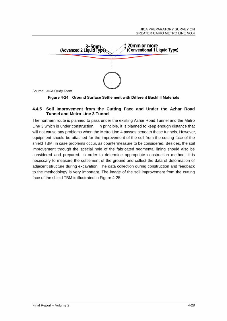
4.4.4 Use of the Two Liquid Type Backfill Material for the Tail Void
The conventional one liquid type backfill material was commonly used before in Japan.
However, it has been replaced with two liquid type backfill material to minimize settlement.
The Phase 2 alternatives are anticipated to encounter neighbouring construction. In order
to execute these without any problem, the settlement caused by the excavation of the
shield TBM must be minimized.
One of the significant reasons for the occurrence of large settlement is the hardening time
of the back fill material. The conventional back fill material of liquid type requires 10 to 12
hours or more to harden and achieve initial strength. Thus, the stiffness of the backfill
material is quite low and deformed by earth pressure above during hardening time.
Consequently, the ground above the tunnel lining and tail void deforms and generates
settlement.
In order to minimize the settlement which is caused by the deformation of backfill material,
it is very effective to use a backfill material that rapidly hardens. The advanced two liquid
type backfill material hardens within 30 minutes and achieves enough strength to resist
earth pressure above. Moreover, it is re-softened and fluidized due to the pressure of the
loaded backfill grouting. Then, the tail void is filled properly and the backfill material rapidly
hardens after the grouting pressure is lightly loaded.
In Section 4.3.1 (1)-c), the practices and experiences of the neighbouring construction
without any countermeasure is introduced. These methods were successfully carried out
with advanced technology such as the two liquid type backfill material.
The conventional liquid type backfill material is a unique method in Egypt and in some
European countries. Therefore, it is strongly recommended to introduce advanced material
types to mitigate the settlement problem and neighbouring construction.
Source: JICA Study Team
Figure 4-23 Mechanism of the Settlement by the Deformation of Backfill Material
Backfill Grouting Pipes
Deformation of Backfill Material
G
Backfill Grouting
Settlement
Segment Lining
Tail Void
JICA PREPARATORY SURVEY ON GREATER CAIRO METRO LINE NO.4
Final Report – Volume 2 4-28
Source: JICA Study Team
Figure 4-24 Ground Surface Settlement with Different Backfill Materials
4.4.5 Soil Improvement from the Cutting Face and Under the Azhar Road Tunnel and Metro Line 3 Tunnel
The northern route is planned to pass under the existing Azhar Road Tunnel and the Metro
Line 3 which is under construction. In principle, it is planned to keep enough distance that
will not cause any problems when the Metro Line 4 passes beneath these tunnels. However,
equipment should be attached for the improvement of the soil from the cutting face of the
shield TBM, in case problems occur, as countermeasure to be considered. Besides, the soil
improvement through the special hole of the fabricated segmental lining should also be
considered and prepared. In order to determine appropriate construction method, it is
necessary to measure the settlement of the ground and collect the data of deformation of
adjacent structure during excavation. The data collection during construction and feedback
to the methodology is very important. The image of the soil improvement from the cutting
face of the shield TBM is illustrated in Figure 4-25.
(Advanced 2 Liquid Type) 20mm or more 3~5mm (Conventional 1 Liquid Type)

JICA PREPARATORY SURVEY ON GREATER CAIRO METRO LINE NO.4
Final Report – Volume 2 4-29
Source: JICA Study Team
Figure 4-25 Image of Soil Improvement from the Cutting Face of the Shield TBM
JICA PREPARATORY SURVEY ON GREATER CAIRO METRO LINE NO.4
Final Report – Volume 2 4-30
4.5 Construction Schedule
4.5.1 Study Condition
The construction schedule is planned based on the following conditions:
1. Tunnel Cross Section: Two Single Track Tunnels
2. Number of Shield TBM: Two for both routes
3. Piles are used for the foundation of the viaduct section
4.5.2 Schedule
The preliminary construction period is studied as shown in Table 4-5. The construction
period covers the commencement of the construction work to the start of operation of the
metro.
The outline of the construction schedule is shown in Figure 4-26 and Figure 4-27.
Table 4-5 Construction Period
Route Period Remarks
Northern Route 6.5 Years 2 TBMs are used. Eastern Route 8.5 Years 2 TBMs are used.
Source: JICA Study Team

JICA
PR
EP
AR
AT
OR
Y S
UR
VE
Y O
N
GR
EA
TE
R C
AIR
O M
ET
RO
LINE
NO
.4
Final R
eport – V
olume 2
4-31
Source: JICA Study Team
Figure 4-26 Construction Schedule of Phase 2 (Northern Route)
Construction Schedule for Phase-2 Northern Route.
1 2 3 4 5 6 7 8 9 10 11 12 13 14 15 16 17 18 19 20 21 22 23 24 25 26 27 28 29 30 31 32 33 34 35 36 37 38 39 40 41 42 43 44 45 46 47 48 49 50 51 52 53 54 55 56 57 58 59 60 61 62 63 64 65 66 67 68 69 70 71 72 73 74 75 76 77 78 79 80 81 82 83 84
1 UNDERGROUND SECTION
(1) Station No.1
(2) Station No.2
(3) Station No.3
(4) Station No.4
(5) Station No.5
(6) Station No.6
(7) Station No.7
(8) Station No.8
(9) Station No.9
(10) Station No.10
(11) Station No.11
(12) Station No.12
(13) Station No.13
(14) Transition Section
(15) Bored Tunnel No.1
(16) Bored Tunnel No.2
(17) Track work
(18)Railway SystemInstallation
(19) Test Running
2 ELEVATED SECTION
(1) Viaduct TRS to No.14
(2) Station No.14
(3) Viaduct No.14 to No.15
(4) Station No.15
(4) Viaduct No.15 to No.16
(5) Station No.16
(6) Viaduct No.16 to No.17
(7) Station No.17
(8) Track work
(9)Railway SystemInstallation
(10) Test Running
TRS : Transition Section
Underground/Sustructure Civil Work
Station Architect and Interior Work
Superstructuire Work
7
Items
1 2 3 4 5 6
Operation Start
Demolition of TBM

JICA
PR
EP
AR
AT
OR
Y S
UR
VE
Y O
N
GR
EA
TE
R C
AIR
O M
ET
RO
LINE
NO
.4
Final R
eport – V
olume 2
4-32
Source: JICA Study Team
Figure 4-27 Construction Schedule of Phase-2 Eastern Route
Construction Schedule for Phase-2 Eastern Route.
1 2 3 4 5 6 7 8 9 10 11 12 13 14 15 16 17 18 19 20 21 22 23 24 25 26 27 28 29 30 31 32 33 34 35 36 37 38 39 40 41 42 43 44 45 46 47 48 49 50 51 52 53 54 55 56 57 58 59 60 61 62 63 64 65 66 67 68 69 70 71 72 73 74 75 76 77 78 79 80 81 82 83 84 85 86 87 88 89 90 91 92 93 94 95 96 97 98 99 100 101 102 103 104 105 ## ## ##
1 UNDERGROUND SECTION
(1) Station No.1
(2) Station No.2
(3) Station No.3
(4) Station No.4
(5) Station No.5
(6) Station No.6
(7) Station No.7
(8) Station No.8
(9) Station No.9
(10) Station No.10
(11) Station No.11
(12) Station No.12
(13) Station No.13
(14) Station No.14
(15) Station No.15
(16) Station No.16
(17) Station No.17
(18) Station No.18
(19) Station No.19
(20) Station No.20
(21) Bored Tunnel No.1
(22) Bored Tunnel No.2
(23) Track work
(24)Railway SystemInstallation
(25) Test Running
Underground/Sustructure Civil Work Superstructuire WorkStation Architect and Interior Work
7 8 9
Items1 2 3 4 5 6
Operation Start
Demolition of TBM

JICA PREPARATORY SURVEY ON GREATER CAIRO METRO LINE NO.4
Final Report – Volume 2 4-33
4.6 Construction Cost
For calculating the construction and procurement costs, items in Table 4-6 and Table 4-7
were taken into consideration.
Table 4-6 Conditions for Cost Estimate Category Description
Pre-conditions • The price is valid as at 2009. • The foreign exchange rate used was USD1 = 5.512 LE. • The construction cost calculation includes a local currency portion and a
foreign currency portion. • The construction cost of power generation plants is not included in the
project cost. • Price escalation rate is 10% per year.
Source: JICA Study Team
Table 4-7 Conditions for Each Corridor for Phase 2
North Corridor
(CREATS Route) East Corridor
(SYSTRA Study Route)
1. Route El Malek El Saleh - El Azhar -
Ghamrah - El Sawaha - El Khosos (Ring Road Exit #18)
El Malek El Saleh - Citadel - Nasr City - Ring Road Crossing
Total Length 18 km 23.5 km Underground section
12.5 km 23.5 km
Elevated section 5.5 km 0 km 2. Station (except El Malek
El Saleh Sta.)
16 stations (Underground 12, Elevated 4)
19 stations (Underground 19)
3. Structures
Tunnel Section TBM – Two Single Track Tunnels
Dia. 6.8 m (outside) Underground station (Common)
Cut and Cover: 220 m x 25 m
Underground station (Particular)
Special Techniques for 2 Station -
Elevated station Viaduct Platform length 170 m - 4. No. of Train 352 car 400 car 5. Required No. of Depot for Phase 2
1 1
Source: JICA Study Team
The following table shows the basic unit cost considered for calculating the outline of
construction and procurement costs.
Basic unit costs are estimated from related previous projects over the world such as “Cairo
Metro Line 3”, ”Delhi Metro in India”, “Jakarta MRT in Indonesia”, “Ho Chi Minh MRT in
Vietnam”, etc…
However, related previous project cost is estimated in a different year. Therefore, the basic
unit price is based on 2009 costs, including price escalation.

JICA PREPARATORY SURVEY ON GREATER CAIRO METRO LINE NO.4
Final Report – Volume 2 4-34
Table 4-8 Basic Unit Cost as of 2009
Items Unit Unit Cost
(million USD) Remarks
Underground Civil Works
km 45 Tunnel: Two Single Track Tunnels
Elevated Civil Work km 10 Track km 3.3 Signal and Telecom, Power Supply
km 16
Underground Station (Depth*: Approx. 20 m)
Unit 40
Underground Station (2 island platform 4 tracks sta.)
Unit 80
Underground Station (Depth*: Approx. 30 m)
Unit 60
Underground Station (Depth*: Approx. 40 m)
Unit 80
Underground Station (HEP & JES )
Unit 80
Hard point for Sewage pipe
Unit 2
Hard point for Manhole Unit 5 Elevated Station Unit 13 Rolling Stock Car 2 Depot Unit 20
*: Depth is up to bottom of cut and cover Source: JICA Study Team
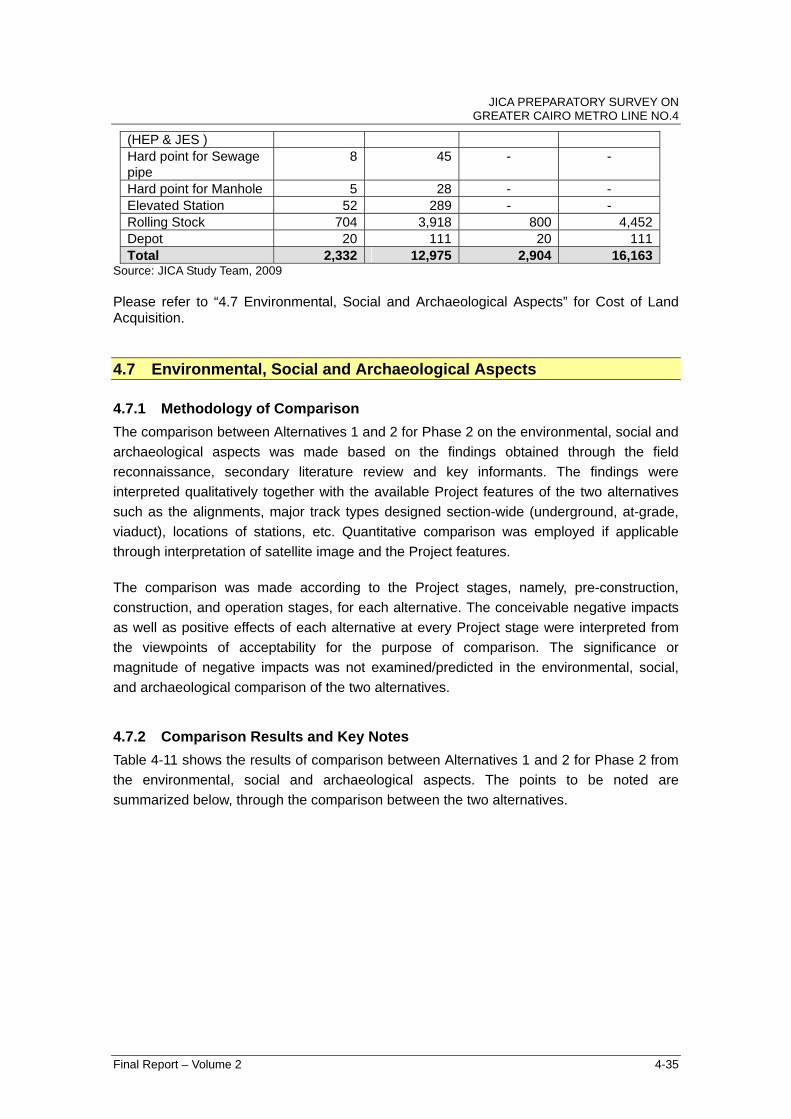
The summary of construction cost in each route is shown in the following Table 4-9.
Table 4-9 Construction and Procurement Cost for Phase 2 as of 2009
Northern Route (CREATS Route)
Eastern Route (SYSTRA Study Route)
Items Million USD
Million LE
Million USD
Million LE
Underground Civil Works
444 2,469 869 4,838
Elevated Civil Work 48 268 - - Track 63 349 79 441 Signal and Telecom, Power Supply
288 1,603 376 2,092
Underground Station (Depth*: Approx. 20 m)
200 1,113 760 4,229
Undergrand Station (2 island platform 4 tracks sta.)
80 445 - -
Underground Station (Depth*: Approx. 30 m)
180 1002 - -
Underground Station (Depth*: Approx. 40 m)
160 890 - -
Underground Station 80 445 - -
JICA PREPARATORY SURVEY ON GREATER CAIRO METRO LINE NO.4
Final Report – Volume 2 4-35
(HEP & JES ) Hard point for Sewage pipe
8 45 - -
Hard point for Manhole 5 28 - - Elevated Station 52 289 - - Rolling Stock 704 3,918 800 4,452 Depot 20 111 20 111 Total 2,332 12,975 2,904 16,163
Source: JICA Study Team, 2009 Please refer to “4.7 Environmental, Social and Archaeological Aspects” for Cost of Land Acquisition.
4.7 Environmental, Social and Archaeological Aspects
4.7.1 Methodology of Comparison
The comparison between Alternatives 1 and 2 for Phase 2 on the environmental, social and
archaeological aspects was made based on the findings obtained through the field
reconnaissance, secondary literature review and key informants. The findings were
interpreted qualitatively together with the available Project features of the two alternatives
such as the alignments, major track types designed section-wide (underground, at-grade,
viaduct), locations of stations, etc. Quantitative comparison was employed if applicable
through interpretation of satellite image and the Project features.
The comparison was made according to the Project stages, namely, pre-construction,
construction, and operation stages, for each alternative. The conceivable negative impacts
as well as positive effects of each alternative at every Project stage were interpreted from
the viewpoints of acceptability for the purpose of comparison. The significance or
magnitude of negative impacts was not examined/predicted in the environmental, social,
and archaeological comparison of the two alternatives.
4.7.2 Comparison Results and Key Notes
Table 4-11 shows the results of comparison between Alternatives 1 and 2 for Phase 2 from
the environmental, social and archaeological aspects. The points to be noted are
summarized below, through the comparison between the two alternatives.

JICA PREPARATORY SURVEY ON GREATER CAIRO METRO LINE NO.4
Final Report – Volume 2 4-36
Alternative 1 Alternative 2 - Total length passing underneath private/public
lands: Approximately 2.5 km. - Major areas to be acquired: the land in front of
Child Cancer Hospital: Approximately 14,000 m2.
- High potential for positive socio-economic effects for local community especially in the poor and densely populated areas.
- Potential negative impacts on water quality in Ismamailia Canal due to the turbid water discharge from the construction sites during construction stage.
- Total length passing underneath private/public lands: Approximately 2.5 km.
- Major areas to be acquired: the land adjacent to the Citadel: Approximately 17,000 m2
- Higher risk of impact on cultural heritage especially in Islamic Cairo due to alignment adjacent to Citadel, etc.
Table 4-10 shows the comparison of magnitude of land acquisition and resettlement
between Alternatives 1 and 2 for Phase 2.
Table 4-10 Comparison of Magnitude of Land Acquisition and Resettlement Parameters Alternative 1 Alternative 2
Necessary Area 14,000 m2 17,000 m2
Number of Resettlement Buildings 11 15Cost for Land Acquisition 138,629,000 LE 204,000,000 LESource: JICA Study Team Remarks: 1: Unit price for land acquisition for alternatives 1 and 2 is based on interview survey at some local real estate and residence. 2: All acquired property is based on the prerequisite condition of owned flat. 3: Cost for land acquisition is calculated based on the maximum price of owned flat which includes land and property. The above estimation just involves the acquisition price of land and properties based on the
available data, and does not include other necessary compensation cost such as financial
support for livelihood stabilization and transaction cost. Other necessary financial support
such as compensation cost and number of potential Project Affected Persons (PAPs) are
under examination, and will be available in the RAP framework report.

JICA PREPARATORY SURVEY ON GREATER CAIRO METRO LINE NO.4
Final Report – Volume 2 4-37
Table 4-11 Comparison of Social, Environmental and Archaeological Aspects
Alternative 1 Alternative 2 ComparisonPre‐construction Stage
>Stations and surface structures are all almost entirely
planned within the right‐of‐way of the existing roads,
therefore, expected negative impact due to
involuntary resettlement is minimal.
>Key note 1: The length passing through underneath
the private/ public lands outside of the right‐of‐way of
the existing roads is roughly estimated 2.5km in total.
>Key note 2: One of the major areas to be acquired for
the Alternative 1 is conceived the land in front of the
Child Cancer Hospital, with approximately 14,000 m2.
>Stations and surface structures are all almost entirely
planned within the right‐of‐way, therefore, expected
negative impact due to involuntary resettlement is
minimal.
>Key note 1: The length passing through underneath
the private/ public lands outside of the right‐of‐way of
the existing roads is roughly estimated 2.5km in total.
>Key note 2: One of the major areas to be acquired for
the Alternative 2 is conceived the land adjacent to the
western border of Citadel area, with approximately
17,000 m2.
>The characteristics of negative impacts in the pre‐construction
stage is considered to be similar between 2 alternatives.
>However, the negative impacts of the Alternative 1 is
considered to be more acceptable due to the less pecuriality
compared with the Alternative 2.
Construction Stage
>Negative local impact is conceivable on businesses
adjacent to construction sites and vulnerable informal
settlers and vendors.
>Traffic congestion is conceivable.
>Negative impact is conceivable on quality of daily
lives of surrounding community
>Negative local impact is conceivable on businesses
adjacent to construction sites and vulnerable informal
settlers and vendors.
>Traffic congestion is conceivable.
>Negative impact is conceivable on quality of daily
lives of surrounding community
>Impact of traffic congestion in Alternative 2 is considered to
be less acceptable due to the higher importance of major
arterial roads of Cairo (Salah Salem and Nasr roads) as
compared to Alternative 1.
Operation Stage
>Physical community division is not expected since the
at‐grade section is limieted along the Ismailia Canal,
which is an existing natural barrier already.
>Significant positive socio‐eonomic effect is expected
on the local community, and on small businesses and
vendors in the poor and densely populated
neighborhood of the stations.
>Positive effect on daily lives of local community is
expected due to congestion relief after modal shifting.
>Physical community division is not expected since
there are no at‐grade sections of the alignment
planned so far.
>Positive socio‐economic effect is expected on local
community.
>Positive effect on daily lives of local community is
expected due to congestion relief after modal shifting.
>The characteristics of negative impacts as well as positive
effects are considered to be similar between 2 alternatives.
>However, Alternative 1 is expected to contribute higher
positive effects as compared with Alternative 2, since
Alternative 1 is designed to pass through poorer and more
densely populated communities, some of which are slums.
Pre‐construction Stage
>No Significant Impact >No Significant Impact > Similar
Construction Stage
>Air pollution and noise pollution are expected due to
construction works and operation of heavy
equipment/ vehicles.
>Potential impact on Ismailia Canal from construction
debris and risks of other solid and liquid waste
leakage, but minimal due to
already existing road construction works throughout
most of this section.
>Air pollution and noise pollution are expected due to
construction works and operation of heavy
equipment/ vehicles.
>The potential impact of Alternative 1 on Ismailia Canal is
considered, although it is mitigatable.
Operation Stage
>Noise & vibrations from rolling stock traffic are
expected especially along the at‐grade/ viaduct
sections.
>Positive effect is expected on the beautification of
the environment, since the present status of regional
landscape environment along some sections is
significantly deteriorated (mainly from Al‐Amiria
Bridge to the terminal station).
>Noise & vibrations from rolling stock traffic are
expected especially along the viaduct sections.
>The characteristics of conceivable negative impacts are almost
similar between 2 alternatives.
>Alternative 1 is likely to contribute a more relative upgrade to
the aesthetics of the local environment as compared with the
current situation.
Pre‐construction Stage
>No Significant Impact >No Significant Impact > Similar
Construction Stage
>Risk of impact is expected on unknown underground
cultural heritage during tunneling and construction of
stations through.
>Risk of impact on cultural heritage is expected in
Islamic Cairo due to alignment adjacent to the Citadel,
historical mosques, and passage under the historic
wall of Cairo.
>Both alternatives are expected to bear the risk of impact on
cultural heritage.
>However, Alternative 2 would pose a higher risk to cause
negative impact on cultural heritage due to its distinctiveness
compared with Alternative 1.
Operation Stage
>No Significant Impact >No Significant Impact > Similar
Social Environmen
tNatural Environmen
t & Pollution
Cultural H
eritage
Source: JICA Study Team
JICA PREPARATORY SURVEY ON GREATER CAIRO METRO LINE NO.4
Final Report – Volume 2 4-38
4.8 Comparison Results by Multi-Criteria Analysis and Recommendation
4.8.1 Multi-Criteria Analysis (MCA)
(1) The Purpose and Methodology of MCA
MCA is a decision-making tool developed for complex multi-faceted problems that include
qualitative and/or quantitative aspects of the problem in the decision-making process.
MCA is a tool that can help evaluate the relative importance of all criteria involved, and
reflect their importance in the final decision-making process.
RANKING AND RATING
The two simplest MCA methodologies that can be used in a Criteria and Indicators (C&I)
assessment are ranking and rating.
Ranking involves assigning each decision element a rank that reflects its perceived degree
of importance relative to the decision being made. The decision elements can then be
ordered according to their rank (first, second. etc.). This methodology is not used in this
report.
Rating is similar to ranking, except that the decision elements are assigned with ‘scores’
between 0 and 10. The scores for all elements being compared must add up to 10. Thus, to
give a high score to one element means that a lower score is given to a different element.
This methodology is applied in this report.
(2) Summarized Condition of Two Alternative Routes
The proposed routes to be compared are “Alternative 1 (Northern Route)”, the route studied
and proposed by CREATS, and “Alternative 2 (Eastern Route)”, the route studied and
proposed in the “Greater Cairo Public Transport Study, Report 2, Integrated Public
Transport Network Scenarios” by SYSTRA. (Figure 8.1.5 and more detailed route is shown
in Report 3, Evaluation of the Third Metro Line Alignment Options, Figure 6.2.1).
The proposed routes for selection must be provided with accompanying information and
data.
The summarized main characteristics of both lines are shown in Table 4-12.

JICA PREPARATORY SURVEY ON GREATER CAIRO METRO LINE NO.4
Final Report – Volume 2 4-39
Table 4-12 Summarized Main Characteristics Alternative 1 (Northern Route) Alternative 2 (Eastern Route) Section El Malek El Saleh – El Azhar –
Ghamrah – El Sawaha – El Khosos (Ring Road Exit No.18)
El Malek El Saleh – Citadel – Nasr City – Ring Road Crossing
Length 18 km 23.5 km Underground section 12.5 km 23.5 km Elevated section 5.5 km 0 kmNumber of stations 16 (except El Malek El Saleh) 19 (except El Malek El Saleh) Structures/construction method
Tunnel section 2 single track tunnels 2 single track tunnels Underground station Cut and cover method Cut and cover method Elevated station Viaduct - No. of train sets 44 sets (352 cars) 50 sets (400 cars) Source: JICA Study Team
The information required will be mixed qualitative and quantitative elements.
The objectives are incorporated in the following list of criteria:
a) Transportation Demand in the Near Future: 2022 and Far Future: 2050
As mentioned in Section 4.1.3, the predicted population and number of
passengers along Alternative 1 (Northern Route) and Alternative 2 (Eastern Route)
shown in Table 4-13 are used for the scoring. The population covered is within a
2,000 m radius from the metro line.
Table 4-13 The Predicted Population and Number of Passengers
Alternative 1 (Northern Route) Alternative 2 (Eastern Route) Year No. of passengers Population No. of passengers Population 2022 1,124,000 4,799,000 714,000 3,451,000 2027 1,181,000 4,916.000 946,000 3,645,000 2050 1,278,000 5,779,000 1,208,000 4,294,000 Source: JICA Study Team
The above table shows that Alternative 1 (Northern Route) has higher priority than
Alternative 2 (Eastern Route) in the near future. However, after a long period, the
population and transport demand of both routes become the same. Therefore,
both routes are necessary to be constructed in order to meet the transportation
demands in future.
b) Cost
The results of cost estimation for the comparison of the routes are shown in Table
4-14.

JICA PREPARATORY SURVEY ON GREATER CAIRO METRO LINE NO.4
Final Report – Volume 2 4-40
Table 4-14 Comparison of Cost Estimation Unit: million LE Alternative 1
(Northern Route) Alternative 2
(Eastern Route) Construction cost Tunnel 2,469 4,838 Viaduct 268 - Track 349 441 Station 4,257 4,229 Depot 111 111 Procurement cost Rolling stock 3,918 4,452 Signal, telecom, power supply and other electro-mechanical cost
1,603 2,092
Total 12,975 16,163 Source: JICA Study Team
c) Hard Points and Construction Easiness
< Alternative 1 (Northern Route) >
Six stations under Port Side Street, with a total length of 1,320 m, needs protection
of the SWWT at stations. Moreover, underpinning for the foundation of flyover and
deep excavation will be necessary to protect the existing tunnel and flyovers.
< Alternative 2 (Eastern Route) >
Since it requires passing under the foundation of the flyover and high-rise
buildings, the foundation should rest on a rock layer and the construction of tunnel
should utilize single track TBM as this will be less problematic.
d) Construction Schedule
The construction period of the north route is expected to be 6.5 years, including
the construction of the station. Meanwhile, the construction period of the east
route is expected to be 8.5 years, including the construction of tunnels with two
sets of TBM.
e) Environment
The length passing underneath private/public lands for both lines is the same,
which is approximately 2.5 km.
- Necessary land acquisition for Alternative 1 (Northern Route) covers the land in
front of the Child Cancer Hospital: Approximately 14,000 m2 + Ghamrah Station:
Approximately 4,000m2.
JICA PREPARATORY SURVEY ON GREATER CAIRO METRO LINE NO.4
Final Report – Volume 2 4-41
- Necessary land acquisition for the east line covers the land adjacent to the
Citadel: Approximately 17,000 m2, including the temporary bus-terminal during
construction.
- Alternative 1 (Northern Route) has high potential in terms of positive
socio-economic contribution to local community especially for the poor and
densely populated areas.
f) Archaeological Assets
< Alternative 1 (Northern Route) >
- Passes close to the Matariya district where some archaeological remains have
been found including Heliopolis, one of the ancient main cities.
- The planned route runs along Port Said Street beside the Ismailiya Canal, which
has enough distance from the archaeological area in Matariya District.
- There is no high possibility of crossing the archaeological property during
construction.
< Alternative 2 (Eastern Route) >
- Regarded as the world's oldest Islamic city, “Historic Cairo” is among UNESCO’s
World Heritage. This area encompasses the famous mosques, citadel, madrasas,
hammams and fountains, with outstanding universal value.
- JICA Study Team’s current plan considers the route line passing through the core
zone as well as the buffer zone registered with the World Heritage area. It also
includes the planned station located between the Citadel and the Ibn Tulun
Mosque, although the whole line runs underground and intends to avoid the area
just under the historical buildings. This aims to consider the landscape and direct
damage of the World Heritage.
- Although the landscape features are taken into account by passing underground,
there is a concern that slight subsidence and vibration during construction and
while in service would affect these historic monuments. In addition, construction in
the historic Cairo area highly increases the potential for finding cultural remains.
(3) Analysis of Two Alternative Routes
The transportation demand for 2027 and 2050, construction cost, hard point, construction
easiness, construction schedule, environmental issues and archaeological issues have
been assessed for Alternative 1 (Northern Route) and Alternative 2 (Eastern Route).
The following table shows the guidelines for scoring each criterion.

JICA PREPARATORY SURVEY ON GREATER CAIRO METRO LINE NO.4
Final Report – Volume 2 4-42
Table 4-15 Criteria for scoring
Criteria/Assessment Higher score Moderate score Lower score
Score (Max. = 10, Min. = 0) 10 to 7 7 to 4 4 to 0 Transportation Demand Near Future: 2022
d> 1 million 1>d>0.8 million 0.8>d
Transportation Demand Far Future: 2050
d> 1 million 1>d>0.8 million 0.8>d
Cost 10>c 15>c>10 c>15 Hard points (Number) 1>h 5>h>1 h>5 Construction Easiness easy moderate hard Construction Schedule Longer moderate shorter
Environment no negative
impact low negative
impact high negative
impact
Archaeological Assets No Possibly Exist Source: JICA Study Team
Criteria can either be unweighted or weighted. Unweighted criteria are assumed to have
the same importance. However, some criteria are considered to be more important than
others. Thus, they should be weighted accordingly. The following table shows the proposed
weighting of criteria.
Table 4-16 Weighting of Criteria
Proposed weighting of criteria Weighting Average per criteria=1
Transportation Demand Near Future: 2022 1.7 Transportation Demand Far Future: 2050 1.2 Cost 1.2 Hard Points 0.8 Construction Easiness 0.7 Construction Schedule 0.8 Environment 0.8 Archaeological Assets 0.9
Source: JICA Study Team Note: The above table indicates that a weighting of less than 1.0 means that a criteria is valued
less than the average, a weight of 1.0 is at the average and a weight of more than 1.0 means it is valued above the average.
The weights of Hard point and construction easiness are lower compared to cost and
construction schedule, because the former criteria are reflected in the cost, construction of
the tunnel and underground structure at Hard points, requiring special construction method
and higher construction cost. Thus, construction easiness means low cost and short
construction schedule.
The following table shows the comparison of the two routes, including near and far future
transportation demands.
JICA PREPARATORY SURVEY ON GREATER CAIRO METRO LINE NO.4
Final Report – Volume 2 4-43
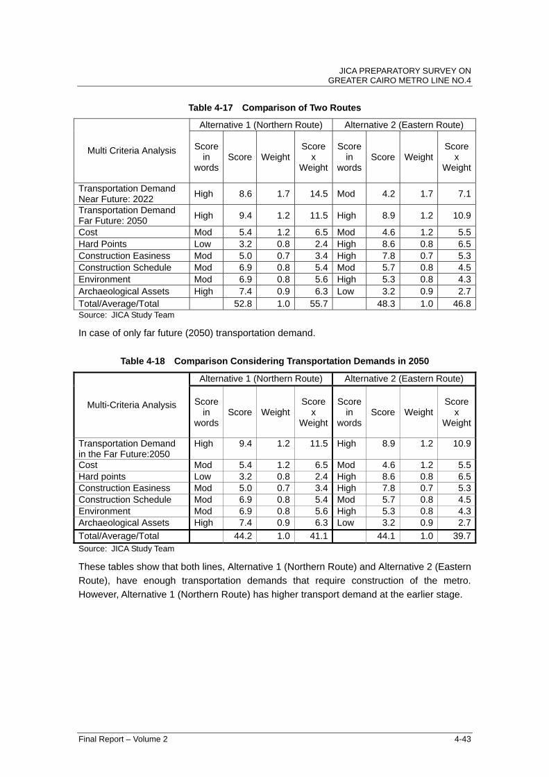
Table 4-17 Comparison of Two Routes
Alternative 1 (Northern Route) Alternative 2 (Eastern Route)
Multi Criteria Analysis Score in
words Score Weight
Scorex
Weight
Score in
wordsScore Weight
Scorex
Weight
Transportation Demand Near Future: 2022
High 8.6 1.7 14.5 Mod 4.2 1.7 7.1
Transportation Demand Far Future: 2050
High 9.4 1.2 11.5 High 8.9 1.2 10.9
Cost Mod 5.4 1.2 6.5 Mod 4.6 1.2 5.5 Hard Points Low 3.2 0.8 2.4 High 8.6 0.8 6.5 Construction Easiness Mod 5.0 0.7 3.4 High 7.8 0.7 5.3 Construction Schedule Mod 6.9 0.8 5.4 Mod 5.7 0.8 4.5 Environment Mod 6.9 0.8 5.6 High 5.3 0.8 4.3 Archaeological Assets High 7.4 0.9 6.3 Low 3.2 0.9 2.7 Total/Average/Total 52.8 1.0 55.7 48.3 1.0 46.8 Source: JICA Study Team
In case of only far future (2050) transportation demand.
Table 4-18 Comparison Considering Transportation Demands in 2050
Alternative 1 (Northern Route) Alternative 2 (Eastern Route)
Multi-Criteria Analysis Score in
words Score Weight
Scorex
Weight
Score in
wordsScore Weight
Scorex
Weight
Transportation Demand in the Far Future:2050
High 9.4 1.2 11.5 High 8.9 1.2 10.9
Cost Mod 5.4 1.2 6.5 Mod 4.6 1.2 5.5 Hard points Low 3.2 0.8 2.4 High 8.6 0.8 6.5 Construction Easiness Mod 5.0 0.7 3.4 High 7.8 0.7 5.3 Construction Schedule Mod 6.9 0.8 5.4 Mod 5.7 0.8 4.5 Environment Mod 6.9 0.8 5.6 High 5.3 0.8 4.3 Archaeological Assets High 7.4 0.9 6.3 Low 3.2 0.9 2.7
Total/Average/Total 44.2 1.0 41.1 44.1 1.0 39.7Source: JICA Study Team
These tables show that both lines, Alternative 1 (Northern Route) and Alternative 2 (Eastern
Route), have enough transportation demands that require construction of the metro.
However, Alternative 1 (Northern Route) has higher transport demand at the earlier stage.
JICA PREPARATORY SURVEY ON GREATER CAIRO METRO LINE NO.4
Final Report – Volume 2 4-44
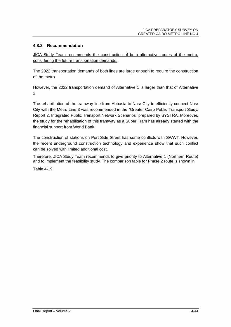
4.8.2 Recommendation
JICA Study Team recommends the construction of both alternative routes of the metro,
considering the future transportation demands.
The 2022 transportation demands of both lines are large enough to require the construction
of the metro.
However, the 2022 transportation demand of Alternative 1 is larger than that of Alternative
2.
The rehabilitation of the tramway line from Abbasia to Nasr City to efficiently connect Nasr
City with the Metro Line 3 was recommended in the “Greater Cairo Public Transport Study,
Report 2, Integrated Public Transport Network Scenarios” prepared by SYSTRA. Moreover,
the study for the rehabilitation of this tramway as a Super Tram has already started with the
financial support from World Bank.
The construction of stations on Port Side Street has some conflicts with SWWT. However,
the recent underground construction technology and experience show that such conflict
can be solved with limited additional cost.
Therefore, JICA Study Team recommends to give priority to Alternative 1 (Northern Route) and to implement the feasibility study. The comparison table for Phase 2 route is shown in
Table 4-19.
JICA PREPARATORY SURVEY ON GREATER CAIRO METRO LINE NO.4
Final Report - Volume 2 4-45
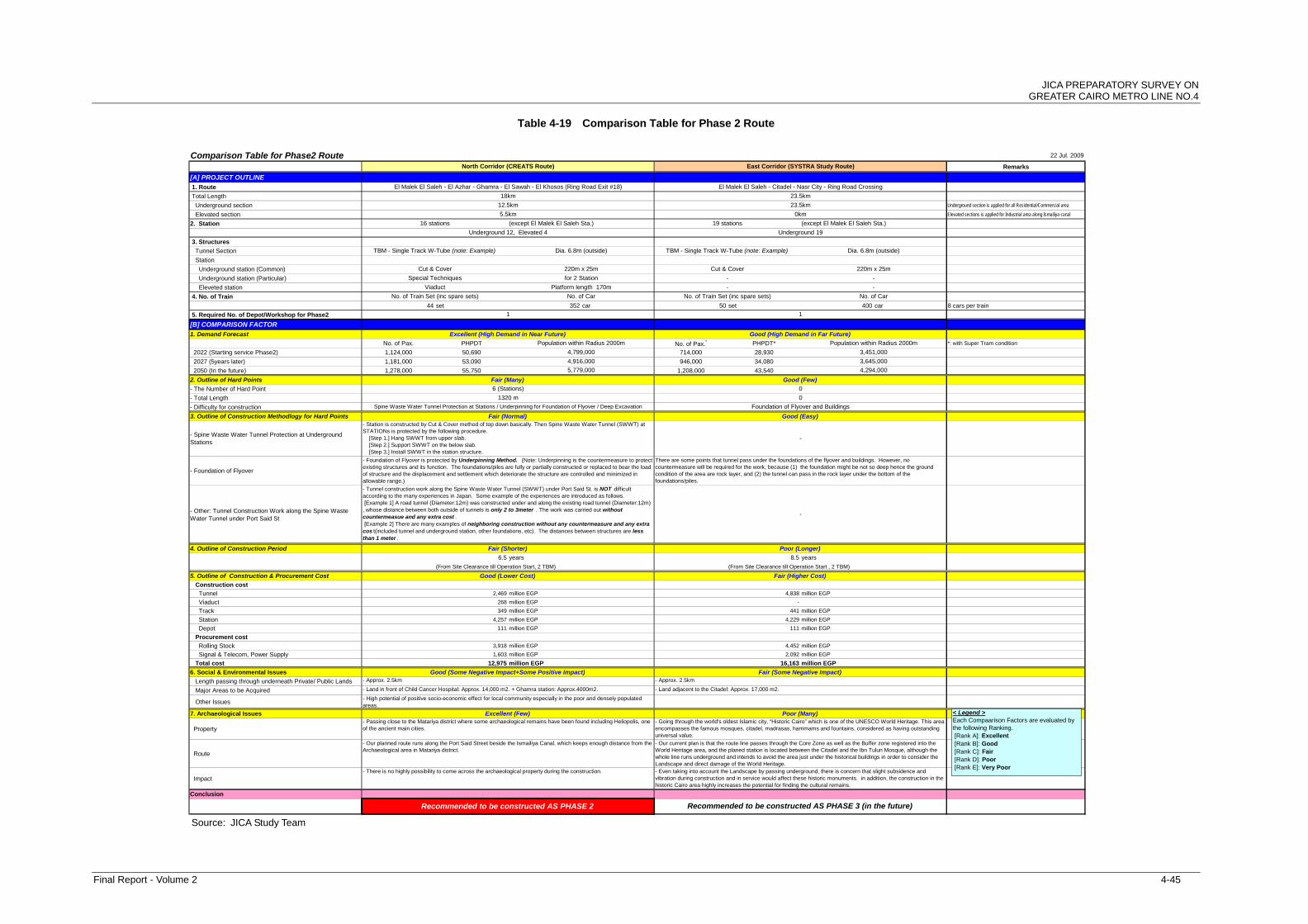
Table 4-19 Comparison Table for Phase 2 Route
Comparison Table for Phase2 Route 22 Jul. 2009
Remarks
[A] PROJECT OUTLINE
1. Route
Total Length
Underground section Underground section is applied for all Residential/Commercial area
Elevated section Elevated sections is applied for Industrial area along Ismailiya canal
2. Station
3. Structures
Tunnel Section
Station
Underground station (Common)
Underground station (Particular)
Eleveted station
4. No. of Train
44 set 352 car 50 set 400 car 8 cars per train
5. Required No. of Depot/Workshop for Phase2
[B] COMPARISON FACTOR
1. Demand Forecast
No. of Pax. PHPDT No. of Pax.* PHPDT* *: with Super Tram condition
2022 (Starting service Phase2) 1,124,000 50,690 714,000 28,930
2027 (5years later) 1,181,000 53,090 946,000 34,080
2050 (In the future) 1,278,000 55,750 1,208,000 43,540
2. Outline of Hard Points
- The Number of Hard Point
- Total Length
- Difficulty for construction
3. Outline of Construction Methodlogy for Hard Points
- Spine Waste Water Tunnel Protection at UndergroundStations
- Foundation of Flyover
- Other: Tunnel Construction Work along the Spine WasteWater Tunnel under Port Said St
4. Outline of Construction Period
6.5 years 8.5 years
(From Site Clearance till Operation Start, 2 TBM) (From Site Clearance till Operation Start , 2 TBM)
5. Outline of Construction & Procurement Cost
Construction cost
Tunnel 2,469 million EGP 4,838 million EGP
Viaduct 268 million EGP -
Track 349 million EGP 441 million EGP
Station 4,257 million EGP 4,229 million EGP
Depot 111 million EGP 111 million EGP
Procurement cost
Rolling Stock 3,918 million EGP 4,452 million EGP
Signal & Telecom, Power Supply 1,603 million EGP 2,092 million EGP
Total cost 12,975 million EGP 16,163 million EGP
6. Social & Environmental Issues
Length passing through underneath Private/ Public Lands
Major Areas to be Acquired
Other Issues
7. Archaeological Issues
Property
Route
Impact
Conclusion
- Tunnel construction work along the Spine Waste Water Tunnel (SWWT) under Port Said St. is NOT difficultaccording to the many experiences in Japan. Some example of the experiences are introduced as follows. [Example 1] A road tunnel (Diameter:12m) was constructed under and along the existing road tunnel (Diameter:12m), whose distance between both outside of tunnels is only 2 to 3meter . The work was carried out withoutcountermeasue and any extra cost . [Example 2] There are many examples of neighboring construction without any countermeasure and any extracos t(included tunnel and underground station, other foundations, etc). The distances between structures are lessthan 1 meter .
-
- Station is constructed by Cut & Cover method of top down basically. Then Spine Waste Water Tunnel (SWWT) atSTATIONs is protected by the following procedure. [Step 1.] Hang SWWT from upper slab. [Step 2.] Support SWWT on the below slab. [Step 3.] Install SWWT in the station structure.
-
- Foundation of Flyover is protected by Underpinning Method. (Note: Underpinning is the countermeasure to protectexisting structures and its function. The foundations/piles are fully or partially constructed or replaced to bear the loadof structure and the displacement and settlement which deteriorate the structure are controlled and minimized inallowable range.)
There are some points that tunnel pass under the foundations of the flyover and buildings. However, nocountermeasure will be required for the work, because (1) the foundation might be not so deep hence the groundcondition of the area are rock layer, and (2) the tunnel can pass in the rock layer under the bottom of thefoundations/piles.
0
1320 m 0
Spine Waste Water Tunnel Protection at Stations / Underpinning for Foundation of Flyover / Deep Excavation Foundation of Flyover and Buildings
- Even taking into account the Landscape by passing underground, there is concern that slight subsidence andvibration during construction and in service would affect these historic monuments. in addition, the construction in thehistoric Cairo area highly increases the potential for finding the cultural remains.
- Passing close to the Matariya district where some archaeological remains have been found including Heliopolis, oneof the ancient main cities.
- Going through the world's oldest Islamic city, “Historic Cairo” which is one of the UNESCO World Heritage. This areaencompasses the famous mosques, citadel, madrasas, hammams and fountains, considered as having outstandinguniversal value.
- Our planned route runs along the Port Said Street beside the Ismailiya Canal, which keeps enough distance from theArchaeological area in Matariya district.
- Our current plan is that the route line passes through the Core Zone as well as the Buffer zone registered into theWorld Heritage area, and the planed station is located between the Citadel and the Ibn Tulun Mosque, although thewhole line runs underground and intends to avoid the area just under the historical buildings in order to consider theLandscape and direct damage of the World Heritage.
- Approx. 2.5km
- Land in front of Child Cancer Hospital: Approx. 14,000 m2. + Ghamra station: Approx.4000m2. - Land adjacent to the Citadel: Approx. 17,000 m2.
Poor (Many)
El Malek El Saleh - El Azhar - Ghamra - El Sawah - El Khosos (Ring Road Exit #18) El Malek El Saleh - Citadel - Nasr City - Ring Road Crossing
Good (Lower Cost) Fair (Higher Cost)
Good (Some Negative Impact+Some Positive Impact) Fair (Some Negative Impact)
Fair (Normal)
- Approx. 2.5km
- High potential of positive socio-economic effect for local community especially in the poor and densely populatedareas.
Cut & Cover
Good (Easy)
1
-
Population within Radius 2000m
No. of Train Set (inc spare sets) No. of Car
Special Techniques
Viaduct
Underground 12, Elevated 4
TBM - Single Track W-Tube (note: Example) Dia. 6.8m (outside)
North Corridor (CREATS Route)
12.5km
18km
16 stations (except El Malek El Saleh Sta.)
5.5km
220m x 25m
for 2 Station
Platform length 170m
Excellent (High Demand in Near Future)
No. of Train Set (inc spare sets) No. of Car
Recommended to be constructed AS PHASE 2
Fair (Shorter)
Excellent (Few)
Fair (Many)
4,916,000
5,779,000
- There is no highly possibility to come across the archaeological property during the construction.
6 (Stations)
East Corridor (SYSTRA Study Route)
23.5km
23.5km
4,799,000
Population within Radius 2000m
3,451,000
Good (High Demand in Far Future)
3,645,000
0km
19 stations (except El Malek El Saleh Sta.)
1
TBM - Single Track W-Tube (note: Example) Dia. 6.8m (outside)
Cut & Cover
4,294,000
Recommended to be constructed AS PHASE 3 (in the future)
Underground 19
-
220m x 25m
-
-
Poor (Longer)
Good (Few)
< Legend >Each Compaarison Factors are evaluated bythe following Ranking. [Rank A]: Excellent [Rank B]: Good [Rank C]: Fair [Rank D]: Poor [Rank E]: Very Poor
Source: JICA Study Team

APPENDIX 1 TRAFFIC COUNT LOCATIONS
JICA PREPARATORY SURVEY ON GREATER CAIRO METRO LINE NO.4
Appendix 1
Traffic Count Locations
Final Report - Volume 2 Appendix1- 1

JICA PREPARATORY SURVEY ON GREATER CAIRO METRO LINE NO.4
LT - 1
El Remayah Square
Mansouria intersection
Final Report - Volume 2 Appendix1- 2

JICA PREPARATORY SURVEY ON GREATER CAIRO METRO LINE NO.4
LT - 3
Mariotiyyah Intersection
LT - 4
Sherbini Intersec.
(Matba'ah)
Final Report - Volume 2 Appendix1- 3

JICA PREPARATORY SURVEY ON GREATER CAIRO METRO LINE NO.4
LT - 5
Kafr Tohormos str.
LT - 6
Sayed Abo –Al-Khaire str.
Final Report - Volume 2 Appendix1- 4

JICA PREPARATORY SURVEY ON GREATER CAIRO METRO LINE NO.4
Final Report - Volume 2 Appendix1- 5
LT-7 -8
LT-8
Giza Tunnel
LT-7
LT - 9- 10- 11 - 12
LT-12
LT-11
LT-10LT-9
Giza Square

APPENDIX 2 TRAFFIC COUNT LOCATIONS AT PORT-SAID STREET

JICA PREPARATORY SURVEY ON GREATER CAIRO METRO LINE NO.4
Appendix 2
Traffic Count Locations
at Port-Said Street
Final Report - Volume 2 Appendix 2-1

JICA PREPARATORY SURVEY ON GREATER CAIRO METRO LINE NO.4
Final Report - Volume 2 Appendix 2-2
LT - 13
LT - 14

JICA PREPARATORY SURVEY ON GREATER CAIRO METRO LINE NO.4 LT - 15
Bab El Shariah
LT - 16
Ghamrah Bridge
Final Report - Volume 2 Appendix 2-3

JICA PREPARATORY SURVEY ON GREATER CAIRO METRO LINE NO.4
LT - 17
LT - 18
Final Report - Volume 2 Appendix 2-4
JICA PREPARATORY SURVEY ON GREATER CAIRO METRO LINE NO.4
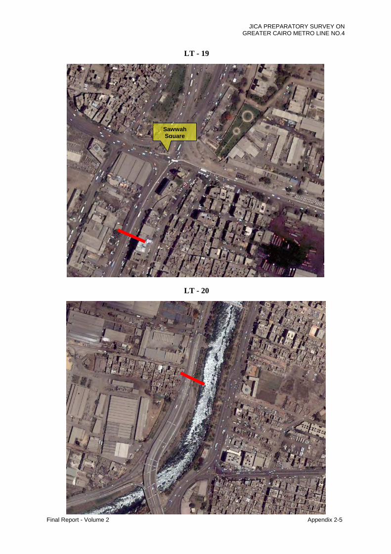
LT - 19
LT - 20
Sawwah Square
Final Report - Volume 2 Appendix 2-5
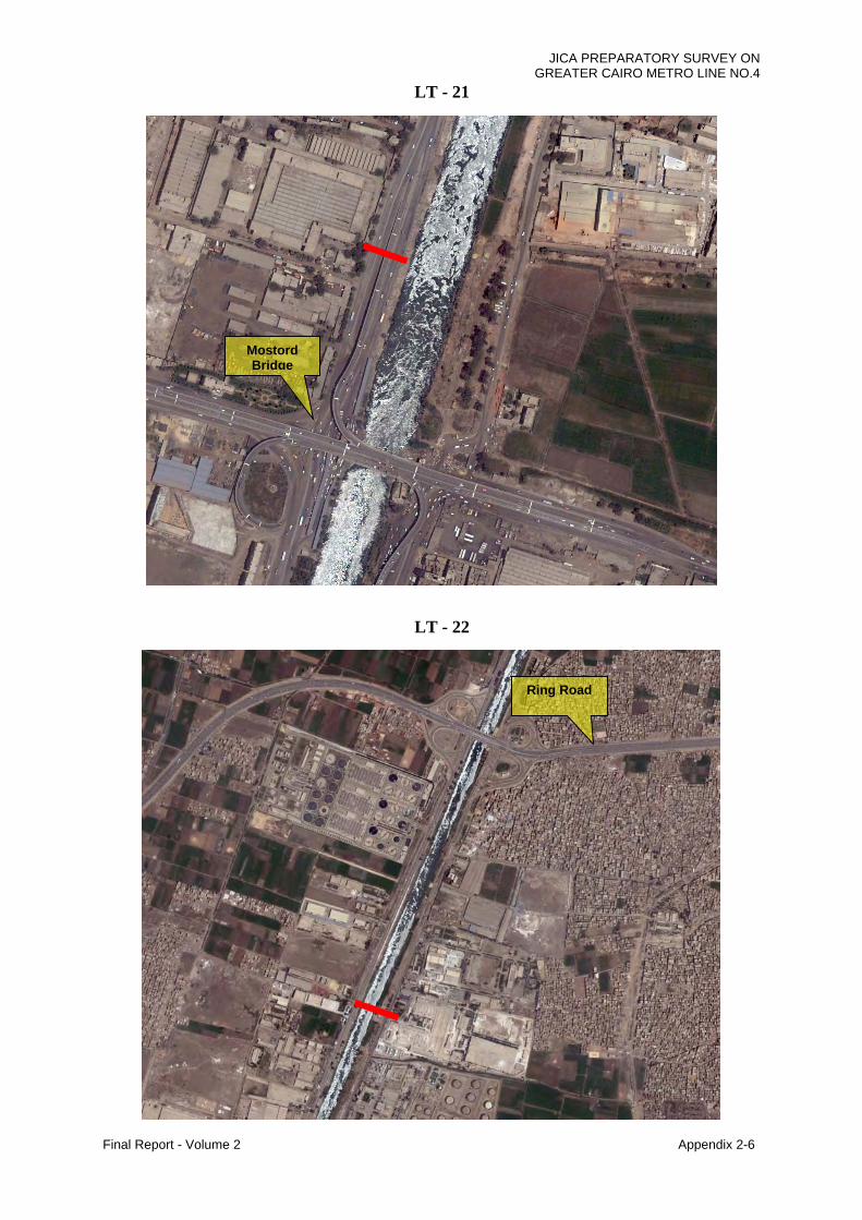
JICA PREPARATORY SURVEY ON GREATER CAIRO METRO LINE NO.4
Final Report - Volume 2 Appendix 2-6
LT - 21
LT - 22
Mostord Bridge
Ring Road