2-story modular classroom building monte vista elementary
TRANSCRIPT
Architect: tBP/Architecture 4611 Teller Ave. Newport Beach, CA 92660-2104 949. 673. 0300
PROJECT MANUAL
Volume 1 of 1 Divisions 00 - 33 September 2021
2-Story Modular Classroom Building Monte Vista Elementary School
tBP Project No. 21056.00 DSA #03 - 121419 File # 19-41 Bid No:
Glendale Unified School District Glendale, California

Glendale Unified School DistrictMonte Vista Elementary School 2-StoryModular Classroom BuildingtBP/Architecture Project No. 21056.00
PROJECT TITLE PAGE00 01 01 - 1
SECTION 00 01 01PROJECT TITLE PAGE
FOR
2-STORY MODULAR CLASSROOM BUILDING
PROJECT NUMBER: 21056.00
DISTRICTGLENDALE UNIFIED SCHOOL DISTRICT
349 WEST MAGNOLIA, GLENDALE, CA 91204818.507.0201
WWW.GUSD.NET
PROJECT LOCATIONMONTE VISTA ELEMENTARY SCHOOL
2620 ORANGE AVENUELA CRESCENTA-MONTROSE , CALIFORNIA 91214
PREPARED BY:
ARCHITECTTBP/ARCHITECTURE
4611 Teller Avenue, Newport Beach, CA 92660
949.673.0300
www.tbparchitecture.com
Glendale Unified School DistrictMonte Vista Elementary School 2-StoryModular Classroom BuildingtBP/Architecture Project No. 21056.00
PROJECT TITLE PAGE00 01 01 - 2
NOTICE: This Project Manual, is an unpublished instrument of service of the authors. It isprepared for use only on this Project and in conjunction with the authors' interpretations, observations,
decisions and administration, as described in the Conditions of the Contract. Desired results withoutthese services cannot be assured. Use in whole or in part, without the authors' services and expressed
written consent may violate Act 17 U.S.C. par. 301 (1991).
END OF PROJECT TITLE PAGE

Glendale Unified School DistrictMonte Vista Elementary School 2-StoryModular Classroom BuildingtBP/Architecture Project No. 21056.00
PROJECT INFORMATION00 01 02 - 1
SECTION 00 01 02PROJECT INFORMATION
PART 1 GENERAL
1.01 PROJECT IDENTIFICATION
A. Project Name: 2-Story Modular Classroom Building, located at:
Project Number: 21056.00.
Monte Vista Elementary School.
2620 Orange Avenue.
La Crescenta-Montrose, California 91214.
B. The Owner, hereinafter referred to as District: Glendale Unified School District
Glendale Unified School District349 West Magnolia, Glendale, CA 91204www.gusd.net818.507.0201
1.02 NOTICE TO PROSPECTIVE BIDDERS
A. These documents constitute an Invitation to Bid to and request for qualifications fromGeneral Contractors for the construction of the project described below.
1.03 PROJECT DESCRIPTION
A. Summary Project Description: Project Description.
B. Contract Scope: Grading and underground utilities, Construction, and demolition.
C. Contract Terms: Lump sum (fixed price, stipulated sum).
1.04 PROJECT CONSULTANTS
A. The Architect, hereinafter referred to as Architect: tBP/Architecture
4611 Teller Avenue, Newport Beach, CA 92660
www.tbparchitecture.com
949.673.0300
1.05 PROCUREMENT DOCUMENTS
A. Availability of Documents: Complete sets of procurement documents may be obtained:
1. From District at the Project Manager's address listed above.
PART 2 PRODUCTS (NOT USED)
PART 3 EXECUTION (NOT USED)
END OF SECTION

Glendale Unified School DistrictMonte Vista Elementary School 2-StoryModular Classroom BuildingtBP/Architecture Project No. 21056.00
PROJECT INFORMATION00 01 02 - 2

Glendale Unified School District Monte Vista Elementary School 2-Story Modular Classroom Building tBP/Architecture Project No. 21056.00
SEALS PAGE 00 01 07 - 1
SECTION 00 01 07
SEALS PAGE
ARCHITECT OF RECORD (AOR)
TBP/ARCHITECTURE
4611 Teller Avenue, Newport Beach, CA 92660
Hung L. Cheng C-34187
MODULAR BUILDING
AMERICAN MODULAR SYSTEMS
797 Spreckels Ave., Manteca, California 95336
Randall Patrick Cavanagh C-12631
STRUCTURAL ENGINEER OF RECORD (SEOR)
VCA ENGINEERS, INC.
2151 Michelson Drive, Suite 240, Irvine, California 92612
Young-Keun Nam S-4029
MECHANICAL ENGINEER OF RECORD (MEOR)
POCOCK DESIGN SOLUTIONS
14451 Chambers Road, Suite 210, Tustin, CA 92780
Andrew Grossman M-35839
ELECTRICAL ENGINEER OF RECORD (EEOR)
FBA ENGINEERING
150 Paularino Avenue, Suite A120, Costa Mesa CA 92626
Stephen R. Zajicek E-10372
DSAD E P A R T M E N T O F G E N E R A L S E R V I C E S
DIVISION OF THE STATE ARCHITECTDSADIVISION OF THE STATE ARCHITECTDSADIVISION OF THE STATE ARCHITECTDSADIVISION OF THE STATE ARCHITECT
IDENTIFICATION STAMP DIV. OF THE STATE ARCHITECT
APP: INC:REVIEWED FOR
SS FLS ACS
DATE:
✔ ✔ ✔
03-121419
09/29/2021

Glendale Unified School District Monte Vista Elementary School 2-Story Modular Classroom Building tBP/Architecture Project No. 21056.00
SEALS PAGE 00 01 07 - 2
CIVIL ENGINEER OF RECORD (CEOR)
FPL & ASSOCIATES
30 Corporate Park, Suite 401, Irvine, California 92606
Alan Wing-Chi Lee, CE C-34971
LANDSCAPE ARCHITECT
SILVER BAR STUDIO
3954 Silverbar Road, Mariposa CA 95338
Craig Thomas Duncan LA-2903
END OF SECTION
DSAD E P A R T M E N T O F G E N E R A L S E R V I C E S
DIVISION OF THE STATE ARCHITECTDSADIVISION OF THE STATE ARCHITECTDSADIVISION OF THE STATE ARCHITECTDSADIVISION OF THE STATE ARCHITECT
IDENTIFICATION STAMP DIV. OF THE STATE ARCHITECT
APP: INC:REVIEWED FOR
SS FLS ACS
DATE:
✔ ✔ ✔
03-121419
09/29/2021
Glendale Unified School DistrictMonte Vista Elementary School 2-StoryModular Classroom BuildingtBP/Architecture Project No. 21056.00
TABLE OF CONTENTS00 01 10 - 1
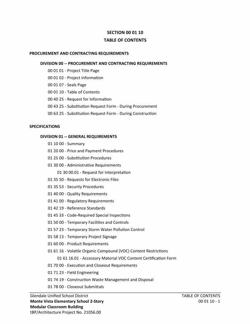
SECTION 00 01 10TABLE OF CONTENTS
PROCUREMENT AND CONTRACTING REQUIREMENTS
DIVISION 00 -- PROCUREMENT AND CONTRACTING REQUIREMENTS
00 01 01 - Project Title Page
00 01 02 - Project Information
00 01 07 - Seals Page
00 01 10 - Table of Contents
00 40 25 - Request for Information
00 43 25 - Substitution Request Form - During Procurement
00 63 25 - Substitution Request Form - During Construction
SPECIFICATIONS
DIVISION 01 -- GENERAL REQUIREMENTS
01 10 00 - Summary
01 20 00 - Price and Payment Procedures
01 25 00 - Substitution Procedures
01 30 00 - Administrative Requirements
01 30 00.01 - Request for Interpretation
01 35 50 - Requests for Electronic Files
01 35 53 - Security Procedures
01 40 00 - Quality Requirements
01 41 00 - Regulatory Requirements
01 42 19 - Reference Standards
01 45 33 - Code-Required Special Inspections
01 50 00 - Temporary Facilities and Controls
01 57 23 - Temporary Storm Water Pollution Control
01 58 13 - Temporary Project Signage
01 60 00 - Product Requirements
01 61 16 - Volatile Organic Compound (VOC) Content Restrictions
01 61 16.01 - Accessory Material VOC Content Certification Form
01 70 00 - Execution and Closeout Requirements
01 71 23 - Field Engineering
01 74 19 - Construction Waste Management and Disposal
01 78 00 - Closeout Submittals

Glendale Unified School DistrictMonte Vista Elementary School 2-StoryModular Classroom BuildingtBP/Architecture Project No. 21056.00
TABLE OF CONTENTS00 01 10 - 2
01 78 00.01 - Warranty Form Letter
01 79 00 - Demonstration and Training
DIVISION 02 -- EXISTING CONDITIONS
02 41 00 - Demolition
DIVISION 03 -- CONCRETE
03 10 00 - Concrete Forming and Accessories
03 20 00 - Concrete Reinforcing
03 30 00 - Cast-in-Place Concrete
DIVISION 05 -- METALS
05 12 00 - Structural Steel Framing
05 50 00 - Metal Fabrications
05 52 13 - Pipe and Tube Railings
DIVISION 07 -- THERMAL AND MOISTURE PROTECTION
07 92 00 - Joint Sealants
DIVISION 09 -- FINISHES
09 96 00 - High-Performance Coatings
DIVISION 10 -- SPECIALTIES
10 14 00 - Signage
10 71 13.43 - Fixed Sun Screens
DIVISION 14 -- CONVEYING EQUIPMENT
14 24 26 - Modular Hydraulic Passenger Elevator
DIVISION 22 -- PLUMBING
22 12 23 - Facility Natural-Gas Piping
22 47 13.13 - Sitework Drinking Fountain and Bottle Filler
DIVISION 26 -- ELECTRICAL
26 05 00 - Common Work Results for Electrical
26 05 01 - Basic Electrical Materials and Methods
26 05 30 - Conduit and Wire
26 24 13 - Switchboards
26 50 00 - Lighting Fixtures
DIVISION 27 -- COMMUNICATIONS
27 21 00 - Electronic Network Systems Infrastructure
Glendale Unified School DistrictMonte Vista Elementary School 2-StoryModular Classroom BuildingtBP/Architecture Project No. 21056.00
TABLE OF CONTENTS00 01 10 - 3
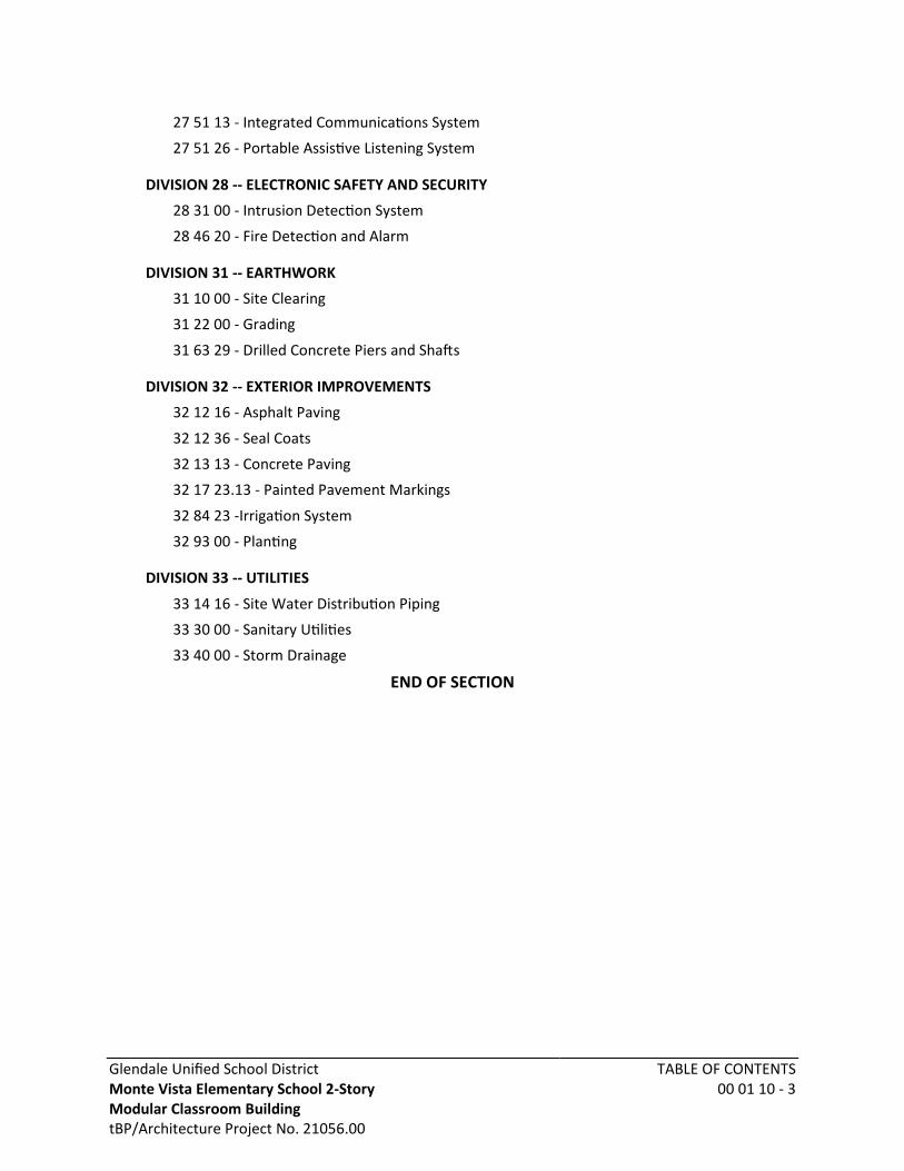
27 51 13 - Integrated Communications System
27 51 26 - Portable Assistive Listening System
DIVISION 28 -- ELECTRONIC SAFETY AND SECURITY
28 31 00 - Intrusion Detection System
28 46 20 - Fire Detection and Alarm
DIVISION 31 -- EARTHWORK
31 10 00 - Site Clearing
31 22 00 - Grading
31 63 29 - Drilled Concrete Piers and Shafts
DIVISION 32 -- EXTERIOR IMPROVEMENTS
32 12 16 - Asphalt Paving
32 12 36 - Seal Coats
32 13 13 - Concrete Paving
32 17 23.13 - Painted Pavement Markings
32 84 23 -Irrigation System
32 93 00 - Planting
DIVISION 33 -- UTILITIES
33 14 16 - Site Water Distribution Piping
33 30 00 - Sanitary Utilities
33 40 00 - Storm Drainage
END OF SECTION

Glendale Unified School DistrictMonte Vista Elementary School 2-StoryModular Classroom BuildingtBP/Architecture Project No. 21056.00
REQUEST FOR INFORMATION00 40 25 - 1
SECTION 00 40 25REQUEST FOR INFORMATION
RFI NUMBER: ________________ DATE: __________
PROJECT NAME: 2-STORY MODULAR CLASSROOM BUILDING PROJECT NO.: 21056.00
TO: TBP/ARCHITECTURE
. 4611 Teller Avenue, Newport Beach, CA 92660
Attention: ________________________________________________________________
Contractor: ________________________________________________________________
Address: ________________________________________________________________
________________________________________________________________
Request By: _________________________________________ Date: __________________
BRIEF SUMMARY OF RFI: __________________________________________________________
____________________________________________________________________________
____________________________________________________________________________
Drawing No. ______________________________________________ Detail No. ___________
Specification Section _______________ Title _______________________________________
. Page _______________ Paragraph _____________
DETAILS OF THIS RFI: _____________________________________________________________
____________________________________________________________________________
____________________________________________________________________________
____________________________________________________________________________
____________________________________________________________________________
____________________________________________________________________________
____________________________________________________________________________
____________________________________________________________________________
____________________________________________________________________________
Attachments: _________________________________________________________________
____________________________________________________________________________
RESPONSE WILL BE INCLUDED IN AN ADDENDUM
END OF RFI

Glendale Unified School DistrictMonte Vista Elementary School 2-StoryModular Classroom BuildingtBP/Architecture Project No. 21056.00
SUBSTITUTION REQUEST FORM -DURING PROCUREMENT
00 43 25 - 1
SECTION 00 43 25SUBSTITUTION REQUEST FORM - DURING PROCUREMENT
SUBSTITUTION REQUEST NO. ________________
DATE: ____________
PROJECT NAME: 2-STORY MODULAR CLASSROOM BUILDING
PROJECT NUMBER: 21056.00
TO: TBP/ARCHITECTURE
. 4611 Teller Avenue, Newport Beach, CA 92660
From: ______________________________________________________________________
We hereby submit for your consideration the following product comparisons of the specifiedproduct and the proposed substitution. The undersigned fully understands that failure toanswer any item below may be cause for rejection of request for substitution.
Request for substitution shall only be made during bidding (not later than 7 days prior to bidopening for inclusion by Addendum) except under conditions beyond control of Contractor.
SPECIFIED PRODUCT: _____________________________________________________________
Project Manual Section Title ____________________ Number ___ Page ____ Paragraph ___.
Drawing No. ______________________________________________ Detail No. ___________
Proposed Substitution: _________________________________________________________
____________________________________________________________________________
Manufacturer: ______________________________________________ Tel: _____________
A. Is the point-by-point comparative data attached? — REQUIRED BY A/E
B. Reason request for substitution is being submitted: __________________________________
____________________________________________________________________________
____________________________________________________________________________
DIFFERENCES BETWEEN PROPOSED SUBSTITUTION AND SPECIFIED PRODUCT
A. Does proposed substitution affect in any way the Structural Safety, Access Compliance, or Fire& Life Safety portions of the project? No__ Yes__
Explain _____________________________________________________________________
____________________________________________________________________________
B. Does proposed substitution affect dimensions, gages, weights, etc. on Drawing? No__ Yes__
Explain _____________________________________________________________________
____________________________________________________________________________
Glendale Unified School DistrictMonte Vista Elementary School 2-StoryModular Classroom BuildingtBP/Architecture Project No. 21056.00
SUBSTITUTION REQUEST FORM -DURING PROCUREMENT
00 43 25 - 2
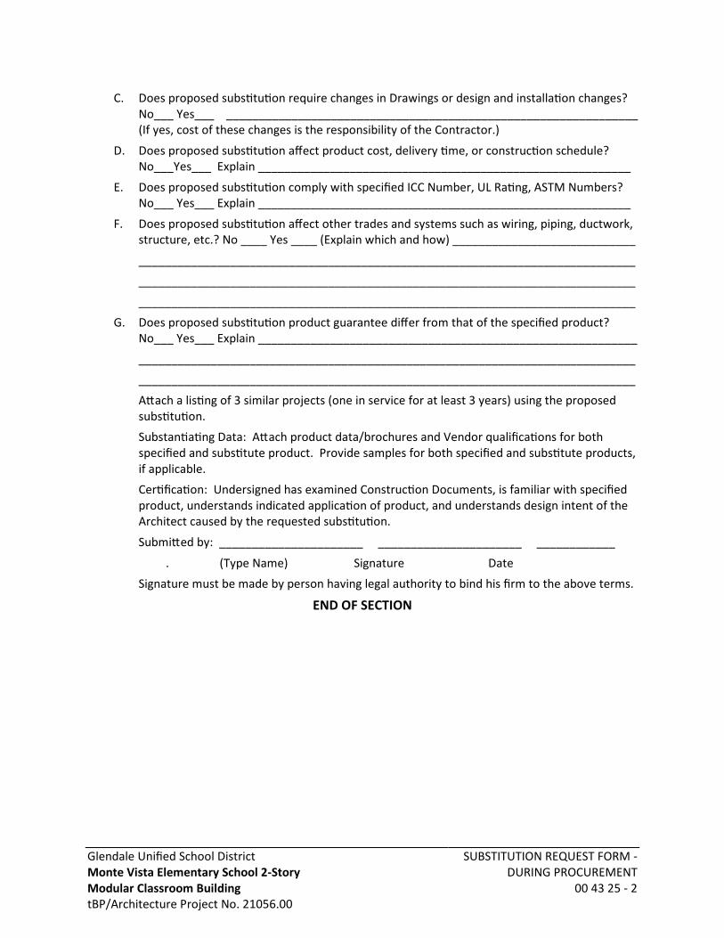
C. Does proposed substitution require changes in Drawings or design and installation changes?No___ Yes___ _______________________________________________________________(If yes, cost of these changes is the responsibility of the Contractor.)
D. Does proposed substitution affect product cost, delivery time, or construction schedule?No___Yes___ Explain _________________________________________________________
E. Does proposed substitution comply with specified ICC Number, UL Rating, ASTM Numbers? No___ Yes___ Explain _________________________________________________________
F. Does proposed substitution affect other trades and systems such as wiring, piping, ductwork,structure, etc.? No ____ Yes ____ (Explain which and how) ____________________________
____________________________________________________________________________
____________________________________________________________________________
____________________________________________________________________________
G. Does proposed substitution product guarantee differ from that of the specified product?No___ Yes___ Explain __________________________________________________________
____________________________________________________________________________
____________________________________________________________________________
Attach a listing of 3 similar projects (one in service for at least 3 years) using the proposedsubstitution.
Substantiating Data: Attach product data/brochures and Vendor qualifications for bothspecified and substitute product. Provide samples for both specified and substitute products,if applicable.
Certification: Undersigned has examined Construction Documents, is familiar with specifiedproduct, understands indicated application of product, and understands design intent of theArchitect caused by the requested substitution.
Submitted by: ______________________ ______________________ ____________
. (Type Name) Signature Date
Signature must be made by person having legal authority to bind his firm to the above terms.
END OF SECTION

Glendale Unified School DistrictMonte Vista Elementary School 2-StoryModular Classroom BuildingtBP/Architecture Project No. 21056.00
SUBSTITUTION REQUEST FORM -DURING CONSTRUCTION
00 63 25 - 1
SECTION 00 63 25SUBSTITUTION REQUEST FORM - DURING CONSTRUCTION
SUBSTITUTION REQUEST NO. ________________
DATE: ____________
PROJECT NAME: 2-STORY MODULAR CLASSROOM BUILDING
PROJECT NUMBER: 21056.00
TO: TBP/ARCHITECTURE
. 4611 Teller Avenue, Newport Beach, CA 92660
From: ______________________________________________________________________
We hereby submit for your consideration the following product comparisons of the specifiedproduct and the proposed substitution. The undersigned fully understands that failure toanswer any item below may be cause for rejection of request for substitution.
This request for substitution form shall only be used after the end of the bidding periodexcept under conditions beyond control of Contractor.
Specified Product: ____________________________________________________________
Project Manual Section Title ____________________ Number ___ Page ____ Paragraph ___.
Drawing No. ______________________________________________ Detail No. ___________
Proposed Substitution: _________________________________________________________
____________________________________________________________________________
Manufacturer: ______________________________________________ Tel: _____________
A. Reason request for substitution is being submitted: __________________________________
____________________________________________________________________________
____________________________________________________________________________
B. Does proposed substitution affect in any way the Structural Safety, Access Compliance, or Fire& Life Safety portions of the project? No__ Yes__
Explain _____________________________________________________________________
____________________________________________________________________________
C. Does proposed substitution affect dimensions, gages, weights, etc. on Drawing? No__ Yes__
Explain _____________________________________________________________________
____________________________________________________________________________
D. Does proposed substitution require changes in Drawings or design and installation changes?No___ Yes___ _______________________________________________________________(If yes, cost of Architect and Engineer document changes are the responsibility of theContractor.)
Glendale Unified School DistrictMonte Vista Elementary School 2-StoryModular Classroom BuildingtBP/Architecture Project No. 21056.00
SUBSTITUTION REQUEST FORM -DURING CONSTRUCTION
00 63 25 - 2
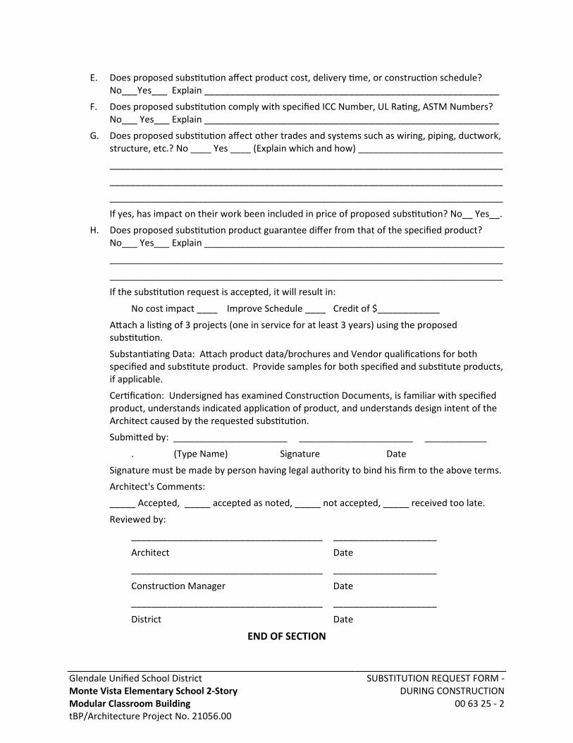
E. Does proposed substitution affect product cost, delivery time, or construction schedule?No___Yes___ Explain _________________________________________________________
F. Does proposed substitution comply with specified ICC Number, UL Rating, ASTM Numbers? No___ Yes___ Explain _________________________________________________________
G. Does proposed substitution affect other trades and systems such as wiring, piping, ductwork,structure, etc.? No ____ Yes ____ (Explain which and how) ____________________________
____________________________________________________________________________
____________________________________________________________________________
____________________________________________________________________________
If yes, has impact on their work been included in price of proposed substitution? No__ Yes__.
H. Does proposed substitution product guarantee differ from that of the specified product?No___ Yes___ Explain __________________________________________________________
____________________________________________________________________________
____________________________________________________________________________
If the substitution request is accepted, it will result in:
No cost impact ____ Improve Schedule ____ Credit of $____________
Attach a listing of 3 projects (one in service for at least 3 years) using the proposedsubstitution.
Substantiating Data: Attach product data/brochures and Vendor qualifications for bothspecified and substitute product. Provide samples for both specified and substitute products,if applicable.
Certification: Undersigned has examined Construction Documents, is familiar with specifiedproduct, understands indicated application of product, and understands design intent of theArchitect caused by the requested substitution.
Submitted by: ______________________ ______________________ ____________
. (Type Name) Signature Date
Signature must be made by person having legal authority to bind his firm to the above terms.
Architect's Comments:
_____ Accepted, _____ accepted as noted, _____ not accepted, _____ received too late.
Reviewed by:
_____________________________________ ____________________
Architect Date
_____________________________________ ____________________
Construction Manager Date
_____________________________________ ____________________
District Date
END OF SECTION

Glendale Unified School DistrictMonte Vista Elementary School 2-StoryModular Classroom BuildingtBP/Architecture Project No. 21056.00
SUMMARY01 10 00 - 1
SECTION 01 10 00SUMMARY
PART 1 GENERAL
1.01 PROJECT
A. Project Name: 2-Story Modular Classroom Building
B. District's Name: Glendale Unified School District.
C. Architect's Name: tBP/Architecture.
D. The Project consists of the alteration of existing relocatable buildings and related siteworklocated at Monte Vista Elementary School.
1.02 CONTRACT DESCRIPTION
A. Contract Type: A single prime contract based on a Stipulated Price as described inOwner-Contractor Agreement.
B. The Work: The Work is construction and related services for a , CBC, Occupancy TypeEducational Group E, Construction Type V-B, , totaling approximately 0 square feet.
1.03 CONTRACT DOCUMENTS
A. Contract Requirements:
1. Conditions of the Contract and other Contract documents have been included in theProject Manual, as indicated in the Table of Contents.a. Such documents are not Specifications.
2. Specifications are found in Divisions 01 through 33 of the Project Manual.
B. Contract Drawings: The Drawings provided with and identified in the Project Manual are theDrawings referenced in the Agreement.
1. The location, extent and configuration of the required construction and improvementsare shown and noted on Drawings.a. The Drawings are referenced in the Agreement.b. An index of Drawings is included in the set of Drawings.
2. Drawings are arranged into series according to design discipline. Such organization andall references to trades, subcontractor, specialty contractor or supplier shall not controlthe Contractor in dividing the Work among subcontractors or in establishing the extentof the Work to be performed by any trade.
3. Where the terms "as shown", "as indicated", "as noted", "as detailed", "as scheduled",or terms of like meaning, are used in the Drawings or Specifications, it shall beunderstood that reference is being made to the Drawings referenced in the Agreement.
4. Where reference to the word "plans" is made anywhere in Drawings, Specifications andrelated Contract Documents, it shall be understood to mean the Drawings referenced inthe Agreement.
C. Contract Specifications: The Specifications provided in the Project Manual are theSpecifications referenced in the Agreement.
Glendale Unified School DistrictMonte Vista Elementary School 2-StoryModular Classroom BuildingtBP/Architecture Project No. 21056.00
SUMMARY01 10 00 - 2
1. Specifications are organized by Divisions and Sections in accordance with therecommended practices of the Construction Specifications Institute.a. Such organization shall not control the Contractor in dividing the Work among
subcontractors or in establishing the extent of Work to be performed by any trade.
2. Specifications are included in the Project Manual, which may also include other Biddingand Contract Documents.a. Contents of the Project Manual are listed in Document 00 01 10 - Table of Contents,
in the Project Manual.
1.04 DESCRIPTION OF ALTERATIONS WORK
A. Scope of demolition and removal work is indicated on drawings and specified in Section 02 4100.
1. The intent of these drawings and specifications are the work of the alteration,rehabilitation, or reconstruction of this facility shall be submitted and approved by DSAbefore proceeding with the repair work. CAC Section 4-317.
B. Scope of alterations work is indicated on drawings.
C. Plumbing: Alter existing system and add new construction, keeping existing in operation.
D. Electrical Power and Lighting: Alter existing system and add new construction, keepingexisting in operation.
E. Fire Suppression Sprinklers: Alter existing system and add new construction, keeping existingin operation.
F. Telephone: Alter existing system and add new construction, keeping existing in operation.
G. Security System: Alter existing system and add new construction, keeping existing inoperation.
H. Communications: Alter existing system and add new construction, keeping existing inoperation.
1.05 WORK BY OWNER
A. Concurrent Work Under Separate Contracts:
1. Work Under Separate Contracts: District will award separate contracts for products andinstallation for interior improvements and other work as may be indicated on Drawingsas NIC (Not in Contract).
2. Relationship to Work Under the Contract:a. Work under the Contract shall include all provisions necessary to make such
concurrent work under separate contracts complete in every respect and fullyfunctional, including field finishing.
b. Provide necessary backing, supports, piping, conduit, conductors and other suchprovisions from point of service to point of connection, as shown on Drawings andspecified herein.
3. Related Contract Documents:a. District will make available, in a timely manner, drawings and specifications of work
under separate contracts for coordination and further description of that work.
Glendale Unified School DistrictMonte Vista Elementary School 2-StoryModular Classroom BuildingtBP/Architecture Project No. 21056.00
SUMMARY01 10 00 - 3
b. Such drawings and other data required for the coordination of the work of separatecontracts with the Work of this Contract may be included with the ContractDocuments.
c. If so, they are provided for convenience only and are not to be considered ContractDocuments produced by Architect or Architect's consultants.
4. Permits, Notices and Fees:a. Permits, Notices and Fees: Notices required by and approvals required of authorities
having jurisdiction for work under separate contracts and related fees will be solelythe responsibility of District.
B. Items noted NIC (Not in Contract) will be supplied and installed by District before SubstantialCompletion.
C. District will supply the following for installation by Contractor:
1. Owner-Furnished Products: District may furnish, for installation by Contractor, productswhich are identified on the Drawings and in the Specifications as OFCI(Owner-Furnished/Contractor-Installed).
2. Relationship to Work Under the Contract:a. Work under the Contract shall include all provisions necessary to fully incorporate
such products into the Work, including, as necessary.1) Fasteners.2) Backing,.3) Supports.4) Piping.5) Conduit.6) Conductors.7) Other such provisions from point of service to point of connection.8) Field finishing, as shown on Drawings and specified herein.
b. See Section 01 30 00 - Administrative Requirements for additional requirements.
1.06 PERMITS, LICENSES AND FEES
A. Permits:
1. For Work included in the Contract, Contractor shall obtain all permits from authoritieshaving jurisdiction and from serving utility companies and agencies.
2. District will reimburse Contractor for amount charged for such permits, withoutmark-up.
3. For Work performed under design/build basis, plan check and permit fees shall beincluded in the Contract Sum.
B. Licenses:
1. Contractor shall obtain and pay all licenses associated with construction activities, suchas business licenses, contractors' licenses and vehicle and equipment licenses.
2. All costs for licenses shall be included in the Contract Sum.
C. Assessments:

Glendale Unified School DistrictMonte Vista Elementary School 2-StoryModular Classroom BuildingtBP/Architecture Project No. 21056.00
SUMMARY01 10 00 - 4
1. District will pay all assessments and utility service connection fees. Costs of assessmentsshall not be included in the Contract Sum.
D. Test and Inspection Fees:
1. Contractor shall pay all fees charged by authorities having jurisdiction and from servingutility companies and agencies, for tests and inspections conducted by those authorities,companies and agencies.
2. District will reimburse Contractor for actual amount of such fees, without mark-up.
3. Refer to Section 01 40 00 - Quality Requirements for additional information on tests andinspections and responsibility for payment of fees.
1.07 OWNER OCCUPANCY
A. District intends to continue to occupy adjacent portions of the existing site during the entireconstruction period.
B. District intends to occupy the Project upon Substantial Completion.
C. Cooperate with District to minimize conflict and to facilitate District's operations.
D. Schedule the Work to accommodate District occupancy.
1.08 CONTRACTOR USE OF SITE AND PREMISES
A. Construction Operations: Limited to areas noted on Drawings.
B. Arrange use of site and premises to allow:
1. District occupancy.
2. Work by Others.
3. Work by District.
4. Use of site and premises by the public.
C. Provide access to and from site as required by law and by District:
1. Emergency Building Exits During Construction: Keep all exits required by code openduring construction period; provide temporary exit signs if exit routes are temporarilyaltered.
2. Site Access:a. Limit access to site to indicated routes and access points as indicated.b. If routes and access points are not indicated, access shall be as approved by District.c. Do not restrict access to adjacent properties and do not restrict access for those
performing work under separate contracts for the District.
3. Do not obstruct roadways, sidewalks, or other public ways without permit.
4. Construction Limit:a. Limit construction activities to areas indicated on Drawings as Project Area or, if not
indicated, to areas within the parcel as described in the legal description on theDrawings.
b. Refer also to Section 01 50 00 - Temporary Construction Facilities and Controls foradditional requirements.

Glendale Unified School DistrictMonte Vista Elementary School 2-StoryModular Classroom BuildingtBP/Architecture Project No. 21056.00
SUMMARY01 10 00 - 5
D. Existing building spaces may not be used for storage.
E. Time Restrictions:
1. Limit conduct of especially noisy, malodorous, and dusty exterior work to localordinances.
F. Utility Outages and Shutdown:
1. Limit disruption of utility services to hours the site is unoccupied.
2. Do not disrupt or shut down life safety systems, including but not limited to firesprinklers and fire alarm system, without 7 days notice to District and authorities havingjurisdiction.
3. Prevent accidental disruption of utility services to other facilities.
1.09 CONSTRUCTION WASTE MANAGEMENT
A. Construction and waste management, complying with Section 01 74 19 - Construction WasteManagement and Disposal, is a requirement for this project.
B. The Contractor, Prime Contractors, and subcontractors all have obligations in meeting therequirements of this specification.
1.10 SPECIFICATION SECTIONS APPLICABLE TO ALL CONTRACTS
A. Unless otherwise noted, all provisions of the sections listed in Division 01 apply to allcontracts. Specific items of work listed under individual contract descriptions constituteexceptions.
END OF SECTION
Glendale Unified School DistrictMonte Vista Elementary School 2-StoryModular Classroom BuildingtBP/Architecture Project No. 21056.00
PRICE AND PAYMENTPROCEDURES
01 20 00 - 1
SECTION 01 20 00PRICE AND PAYMENT PROCEDURES
PART 1 GENERAL
1.01 SECTION INCLUDES
A. Procedures for preparation and submittal of applications for progress payments.
B. Documentation of changes in Contract Sum and Contract Time.
C. Change procedures.
D. Correlation of Contractor submittals based on changes.
E. Procedures for preparation and submittal of application for final payment.
1.02 RELATED REQUIREMENTS
A. Section 01 78 00 - Closeout Submittals: Project record documents.
1.03 SCHEDULE OF VALUES
A. Use Schedule of Values Form:
1. Form provided by District.
B. Electronic media printout including equivalent information will be considered in lieu ofstandard form specified; submit draft to Architect for approval.
C. Forms filled out by hand will not be accepted.
D. Submit Schedule of Values in duplicate within 15 days after date established in Notice toProceed.
E. Format: Utilize the Table of Contents of this Project Manual. Identify each line item withnumber and title of the specification section. Identify site mobilization.
F. Include in each line item, the amount of Allowances specified in this section. For unit costAllowances, identify quantities taken from Contract Documents multiplied by the unit cost toachieve the total for the item.
G. Include separately from each line item, a direct proportional amount of Contractor's overheadand profit.
H. Revise schedule to list approved Change Orders, with each Application For Payment.
1. List each authorized Change Order as an extension on the continuation sheet, listing theChange Order number and dollar value as for an original portion of Work.
1.04 APPLICATIONS FOR PROGRESS PAYMENTS
A. Payment Period: Submit at intervals stipulated in the Agreement.
1. Substantiating information will normally be required only for those portions of Workwhose completion state cannot be readily determined by observation of the completedWork.
B. Use Form AIA G702 and Form AIA G703, edition stipulated in the Agreement.

Glendale Unified School DistrictMonte Vista Elementary School 2-StoryModular Classroom BuildingtBP/Architecture Project No. 21056.00
PRICE AND PAYMENTPROCEDURES
01 20 00 - 2
C. Electronic media printout including equivalent information will be considered in lieu ofstandard form specified; submit sample to Architect for approval.
D. Forms filled out by hand will not be accepted.
E. For each item, provide a column for listing each of the following:
1. Item Number.
2. Description of work.
3. Scheduled Values.
4. Previous Applications.
5. Work in Place and Stored Materials under this Application.
6. Authorized Change Orders.
7. Total Completed and Stored to Date of Application.
8. Balance to Finish.
9. Retainage.
F. Execute certification by signature of authorized officer.
G. Use data from approved Schedule of Values. Provide dollar value in each column for each lineitem for portion of work performed and for stored products.
H. List each authorized Change Order as a separate line item, listing Change Order number anddollar amount as for an original item of work.
1. No Change Orders shall be included with Application for Payment until approved inwriting by District and Architect. Also approved by DSA when appropriate.
I. Submit one electronic and three hard-copies of each Application for Payment.
J. Include the following with the application:
1. Transmittal letter as specified for submittals in Section 01 30 00.
2. Construction progress schedule, revised and current as specified in Section 01 30 00.
3. Current construction photographs specified in Section 01 30 00.
4. Partial release of liens from major subcontractors and vendors.a. Provide with each Application for Payment lien releases from all subcontractors,
workers and materials suppliers employed for the Project covering their portion ofWork to date for which payment application is made. Lien release forms will beprovided by District and shall be completed in accordance with directions provided.
5. Project record documents as specified in Section 01 78 00, for review by District whichwill be returned to the Contractor.
6. Affidavits attesting to off-site stored products.
K. When Architect requires substantiating information, submit data justifying dollar amounts inquestion. Provide one copy of data with cover letter for each copy of submittal. Showapplication number and date, and line item by number and description.

Glendale Unified School DistrictMonte Vista Elementary School 2-StoryModular Classroom BuildingtBP/Architecture Project No. 21056.00
PRICE AND PAYMENTPROCEDURES
01 20 00 - 3
1.05 ADDENDA
A. Addenda are changes issued prior to the signing of the Contract for Construction. TheseAddenda shall be signed by the Architect and approved by the Division of the State Architect.
B. These documents may or may not have approved by the Division of the State Architect priorto the close of Bid.
1. If not approved by DSA prior to close of the bidding period, the contract price shallinclude the Addenda.
2. No work shall proceed regarding any Addendum until approved by DSA.
3. Revisions to Addenda, when approved by DSA, shall be incorporated by an additionaladdendum or Change Order as indicated below and as provided for in the Contract forConstruction and General Conditions.
1.06 MODIFICATION PROCEDURES
A. Construction Changes, General:
1. The following describe administrative procedures to be followed in compliance withprovisions of the Conditions of the Contract for Architect's Supplemental Instructions,Construction Change Directives, Construction Change Documents, and Contract ChangeOrders.
2. The Architect will prepare and issue: Architect's Supplemental Instructions, aConstruction Change Directive or a Request for Proposal to be presented to theContractor for action.
B. Submit name of the individual authorized to receive change documents and who will beresponsible for informing others in Contractor's employ or subcontractors of changes to Contract Documents.
C. Contract Change Order Forms: Form as directed by District.
D. For minor changes not involving an adjustment to the Contract Sum or Contract Time,Architect will issue instructions directly to Contractor.
1. Architect's Supplemental Instructions:a. Minor changes in the Work, not involving an adjustment in either the Contract Sum
or Contract Time, as authorized by the Conditions of the Contract, will be presentedby the Architect using the Architect's Bulletin form.
b. Should the Architect's Supplemental Instructions result in disputed costs and timeadjustments, such dispute shall be resolved in accordance with the provisions of theConditions of the Contract.
E. DSA Construction Change Document approval for substitutions and changes to structural,accessibility, or fire-life-safety portions of approved Drawings and Specifications is requiredfrom DSA prior to fabrication and installation. DSA IR A-6; CAC Section 4-215, & 4-233(c).
1. The approved Construction Change Document shall be signed by:a. Architect of Record.b. When applicable:
1) Structural Engineer of Record.2) Mechanical Engineer of Record.
Glendale Unified School DistrictMonte Vista Elementary School 2-StoryModular Classroom BuildingtBP/Architecture Project No. 21056.00
PRICE AND PAYMENTPROCEDURES
01 20 00 - 4
3) Electrical Engineer of Record.4) Civil Engineer of Record.5) Delegated Professional Engineer.
c. Division of the State Architect for final approval.
F. For other required changes, not involving structural, accessibility, or fire-life-safety portions ofapproved Drawings and Specifications, Architect will issue a document signed by Districtinstructing Contractor to proceed with the change, for subsequent inclusion in a ChangeOrder.
1. The document will describe the required changes and will designate method ofdetermining any change in Contract Sum or Contract Time.
2. Promptly execute the change.
3. Construction Change Directives: In accordance with provisions of the Conditions of theContract, the District may direct the Contractor to proceed with a change in the Workprior to formal preparation, review and agreement of a Contract Change Order, in orderto not delay construction.a. The Architect will prepare and issue a change document containing a Construction
Change Directive which, when signed by the District and the Architect, shall instructthe Contractor to proceed with a change in the Work, for subsequent inclusion in aContract Change Order.
b. Should the Construction Change Directive result in disputed costs and timeadjustments, such dispute shall be resolved in accordance with the provisions of theConditions of the Contract.
c. Construction Change Directives shall follow procedures specified below for ContractChange Orders except that Contractor shall immediately proceed with the changeupon receipt of the signed Change Directive.
G. For changes for which advance pricing is desired, Architect will issue a document that includesa detailed description of a proposed change with supplementary or revised drawings andspecifications, a change in Contract Time for executing the change with a stipulation of anyovertime work required and the period of time during which the requested price will beconsidered valid. Contractor shall prepare and submit a fixed price quotation within 14 days.
1. Such Request for Proposal may include an estimate of additions or deductions inContract Time and Contract Sum for executing the change and may include stipulationsregarding overtime work and the period of time the requested response from theContractor shall be considered valid.
H. Contractor may propose a change by submitting a request for change to Architect, describingthe proposed change and its full effect on the work, with a statement describing the reasonfor the change, and the effect on the Contract Sum and Contract Time with fulldocumentation and a statement describing the effect on work by separate or othercontractors. Document any requested substitutions in accordance with Section 01 60 00.
1. After review of the request and with the District's approval, the Architect will prepare achange document containing a Request for Proposal, as described above.
2. Issuance of such a request by the Architect shall not indicate authorization of theContractor to proceed with the proposed change.
Glendale Unified School DistrictMonte Vista Elementary School 2-StoryModular Classroom BuildingtBP/Architecture Project No. 21056.00
PRICE AND PAYMENTPROCEDURES
01 20 00 - 5
3. Changes will be approved only by an approved Construction Change Directive andContract Change Order.
I. Computation of Change in Contract Amount: As specified in the Agreement and Conditions ofthe Contract.
1. For change requested by Architect for work falling under a fixed price contract, theamount will be based on Contractor's price quotation.
2. For change requested by Contractor, the amount will be based on the Contractor'srequest for a Change Order as approved by Architect.
3. For pre-determined unit prices and quantities, the amount will based on the fixed unitprices.
4. For change ordered by Architect without a quotation from Contractor, the amount willbe determined by Architect based on the Contractor's substantiation of costs asspecified for Time and Material work.
J. Substantiation of Costs: Provide full information required for evaluation.
1. On request, provide the following data:a. Quantities of products, labor, and equipment.b. Taxes, insurance, and bonds.c. Overhead and profit.d. Justification for any change in Contract Time.e. Credit for deletions from Contract, similarly documented.
2. Support each claim for additional costs with additional information:a. Origin and date of claim.b. Dates and times work was performed, and by whom.c. Time records and wage rates paid.d. Invoices and receipts for products, equipment, and subcontracts, similarly
documented.
3. For Time and Material work, submit itemized account and supporting data aftercompletion of change, within time limits indicated in the Conditions of the Contract.a. Cost and Time Resolution: If amounts for changes in Contract Sum and Contract
Time cannot be agreed upon by District and Contractor, amounts shall be resolvedin accordance with provisions of the Conditions of the Contract for resolution ofdisputes and the following:1) Contractor shall keep accurate records of time, both labor and calendar days,
and cost of materials and equipment.2) Contractor shall prepare and submit an itemized account and supporting data
after completion of changed Work, within the time limits indicated in theConditions of the Contract.
3) Contractor shall provide full information as required and requested, for Districtand Architect to evaluate and substantiate proposed costs and time for thechange in the Work.

Glendale Unified School DistrictMonte Vista Elementary School 2-StoryModular Classroom BuildingtBP/Architecture Project No. 21056.00
PRICE AND PAYMENTPROCEDURES
01 20 00 - 6
4) When District and Contractor determine mutually acceptable amounts forchanges in Contract Sum and Contract Time, a Contract Change Order shall beexecuted for these amounts.
5) District shall have the right to audit Contractor's invoices and bid quotations tosubstantiate costs for Contract Change Orders.
K. Construction Changes Based on Stipulated Sum or Time: Based on the Contractor's responseto a Request for Proposal or Construction Change Directive, the District and Architect willreview the response.
1. The District and Contractor shall negotiate a mutually acceptable adjustment in ContractSum and Contract Time, as appropriate, prior to performance of the changed Work.
2. A Contract Change Order for the stipulated amounts shall be prepared based on thestipulated sum and change in time.
L. Execution of Change Orders: Architect will issue Change Orders for signatures of parties asprovided in the Conditions of the Contract.
1. When agreement is reached on changes, if any, in the Contract Time and the ContractSum, the Contractor shall prepare a Contract Change Order using a form as directed bythe District, with supplementary documents as necessary to describe the change and theassociated costs and schedule impacts.
2. Construction Change Document approval is required from DSA prior to fabrication andinstallation.
3. Submit Contract Change Orders to District through the Architect.
4. Contractor shall prepare and submit five original sets of documents for each ChangeOrder. District, Architect and Construction Manager shall sign the Change Orderindicating acceptance and approval of the change.a. Structural Engineer shall also sign the Change Order, when applicable.
5. All Change Orders must be approved by DSA prior to fabrication and installation.
6. Upon approval of the Change Order, Contractor shall promptly execute the change in theWork.
M. After execution of Change Order, promptly revise Schedule of Values and Application forPayment forms to record each authorized Change Order as a separate line item and adjust theContract Sum.
N. Promptly revise progress schedules to reflect any change in Contract Time, revisesub-schedules to adjust times for other items of work affected by the change, and resubmit.
1. Contractor shall submit revised schedules at the next Application for Payment followingapproval and acceptance of the Contract Change Order.
O. Promptly enter changes in Project Record Documents.
1.07 APPLICATION FOR FINAL PAYMENT
A. Prepare Application for Final Payment as specified for progress payments, identifying totaladjusted Contract Sum, previous payments, and sum remaining due.
B. Application for Final Payment will not be considered until the following have beenaccomplished:
Glendale Unified School DistrictMonte Vista Elementary School 2-StoryModular Classroom BuildingtBP/Architecture Project No. 21056.00
PRICE AND PAYMENTPROCEDURES
01 20 00 - 7
1. All closeout procedures specified in Section 01 70 00.
PART 2 PRODUCTS - NOT USED
PART 3 EXECUTION - NOT USED
END OF SECTION
Glendale Unified School DistrictMonte Vista Elementary School 2-StoryModular Classroom BuildingtBP/Architecture Project No. 21056.00
SUBSTITUTION PROCEDURES01 25 00 - 1
SECTION 01 25 00SUBSTITUTION PROCEDURES
PART 1 GENERAL
1.01 SECTION INCLUDES
A. Procedural requirements for proposed substitutions.
1.02 RELATED REQUIREMENTS
A. Division 00 - Procurement and Contracting Requirements: Restrictions on timing ofsubstitution requests.
B. Section 00 43 25 - Substitution Request Form - During Procurement: Required form forsubstitution requests made prior to award of contract (During procurement).
C. Section 00 63 25 - Substitution Request Form - During Construction: Required form forsubstitution requests made after award of contract (During construction).
D. Section 01 30 00 - Administrative Requirements: Submittal procedures, coordination.
E. Section 01 60 00 - Product Requirements: Fundamental product requirements, productoptions, delivery, storage, and handling.
F. Section 01 61 16 - Volatile Organic Compound (VOC) Content Restrictions: Restrictions on emissions of indoor substitute products.
1.03 DEFINITIONS
A. Substitutions: Changes from Contract Documents requirements proposed by Contractor tomaterials, products, assemblies, and equipment.
1. Substitutions for Cause: Proposed due to changed Project circumstances beyondContractor's control.a. Unavailability.b. Regulatory changes.
2. Substitutions for Convenience: Proposed due to possibility of offering substantialadvantage to the Project.a. Substitution requests offering advantages solely to the Contractor will not be
considered.
PART 2 PRODUCTS - NOT USED
PART 3 EXECUTION
3.01 GENERAL REQUIREMENTS
A. Requests by Contractor to deviate from specified requirements for products, materials,equipment, and methods, or to provide products other than those specified, shall beconsidered requests for substitutions except under the following conditions:
Glendale Unified School DistrictMonte Vista Elementary School 2-StoryModular Classroom BuildingtBP/Architecture Project No. 21056.00
SUBSTITUTION PROCEDURES01 25 00 - 2
1. Substitutions are requested during the bidding period, and accepted prior to executionof the Contract. Acceptance shall be in the form of written Addendum to the Biddingdocuments or revision to the Drawings or Specifications for use as Construction ContractDocuments.
2. Changes in products, materials, equipment, and methods of construction are directed bythe District or Architect.
3. Contractor options for provision of products and construction methods are specificallystated in the Contract Documents.
4. Change in products, materials, equipment, and methods of construction is required forcompliance with Codes, ordinances, regulations, orders and standards of authoritieshaving jurisdiction.
B. Substitution Provisions: Refer to substitution provisions of the Conditions of the Contract, inaddition to the requirements specified herein. Provisions for consideration and acceptance ofsubstitutions shall be as follows:
1. Documentation:a. Substitutions will not be considered if they are indicated or implied on shop
drawing, product data or sample submittals.b. All requests for substitution shall be made by separate written request from
Contractor.
2. Cost and Time Considerations: Substitutions will not be considered unless a netreduction in Contract Sum or Contract Time results to the District's benefit, includingredesign costs, life cycle costs, changes in related Work and overall performance ofbuilding systems.
3. Design Revision:a. Substitutions will not be considered if acceptance will require substantial revision of
the Contract Documents or will substantially change the intent of the design, in theopinion of the Architect.
b. The intent of the design shall include functional performance and aestheticqualities.
4. Data: It shall be the responsibility of the Contractor to provide adequate datademonstrating the merits of the proposed substitution, including cost data andinformation regarding changes in related Work.
5. Determination by Architect:a. Architect will determine the acceptability of proposed substitutions and will notify
Contractor, in writing within a reasonable time, of acceptance or rejection.b. The determination by the Architect regarding functional performance and aesthetic
quality shall be final.
6. Non-Acceptance: If a proposed substitution is not accepted, provide the specifiedproduct.a. If, in the opinion of the Architect, the substitution request is incomplete or has
insufficient data to enable a full and thorough review of the intended substitution,the substitution may be summarily refused and determined to be unacceptable.

Glendale Unified School DistrictMonte Vista Elementary School 2-StoryModular Classroom BuildingtBP/Architecture Project No. 21056.00
SUBSTITUTION PROCEDURES01 25 00 - 3
7. Substitution Limitation: Only one request for substitution will be considered for eachproduct.
C. A Substitution Request for products, assemblies, materials, and equipment constitutes arepresentation that the submitter:
1. Has investigated proposed product and determined that it meets or exceeds the qualitylevel of the specified product, equipment, assembly, or system.a. Include a signed certification that the Contractor has:
1) Reviewed the proposed substitution and has determined that the substitutionis equivalent or superior in every respect to product requirements indicated orproduct specified in the Contract Documents.
2) Certify the proposed substitution is suited for and can perform the purpose orapplication of the specified product indicated or specified in the ContractDocuments.
2. Agrees to provide the same warranty for the substitution as for the specified product.
3. Agrees to provide same or equivalent maintenance service and source of replacementparts, as applicable.
4. Agrees to coordinate installation and make changes to other work that may be requiredfor the work to be complete, with no additional cost to District.
5. Waives claims for additional costs or time extension that may subsequently becomeapparent.a. Include a signed waiver by the Contractor for changes in the Contract Time or
Contract Sum because of the following:1) Substitution failed to perform adequately.2) Substitution required changes in on other elements of the Work.3) Substitution caused problems in interfacing with other elements of the Work.4) Substitution was determined to be unacceptable by authorities having
jurisdiction.
6. Agrees to reimburse District and Architect for review or redesign services associatedwith re-approval by authorities.
D. A Substitution Request for specified installer constitutes a representation that the submitter:
1. Has acted in good faith to obtain services of specified installer, but was unable to cometo commercial, or other terms.
E. Document each request with complete data substantiating compliance of proposedsubstitution with Contract Documents. Burden of proof is on proposer.
1. Note explicitly any non-compliant characteristics.
F. Content: Include information necessary for tracking the status of each Substitution Request,and information necessary to provide an actionable response.
1. Forms indicated and included in the Project Manual are adequate for this purpose, andmust be used.
2. No specific form is required. Contractor's Substitution Request documentation mustinclude the following:a. Project Information:
Glendale Unified School DistrictMonte Vista Elementary School 2-StoryModular Classroom BuildingtBP/Architecture Project No. 21056.00
SUBSTITUTION PROCEDURES01 25 00 - 4
1) Official project name and number, and any additional required identifiersestablished in Contract Documents.
2) District's, Architect's, and Contractor's names.b. Substitution Request Information:
1) Discrete and consecutive Substitution Request number, and descriptivesubject/title.
2) Indication of whether the substitution is for cause or convenience.3) Issue date.4) Reference to particular Contract Document(s) specification section number,
title, and article/paragraph(s).5) Description of Substitution.6) Reason why the specified item cannot be provided.7) Differences between proposed substitution and specified item.8) Description of how proposed substitution affects other parts of work.
c. Attached Comparative Data: Provide point-by-point, side-by-side comparisonaddressing essential attributes specified, as appropriate and relevant for the item:1) Physical characteristics.2) In-service performance.3) Expected durability.4) Visual effect.5) Sustainable design features.6) Warranties.7) Other salient features and requirements.8) Include, as appropriate or requested, the following types of documentation:
(a) Product Data:(b) Samples.(c) Certificates, test, reports or similar qualification data.(d) Drawings, when required to show impact on adjacent construction
elements.9) Include a detailed description, in written or graphic form as appropriate,
indicating all changes or modifications needed to other elements of the Workand to construction to be performed by the District and by others underseparate Contract with District, that will be necessary if the proposedsubstitution is accepted.
d. Impact of Substitution:1) Savings to District for accepting substitution.
(a) Include detailed cost data, including a proposal for the net change, if any,in the Contract Sum.
2) Change to Contract Time due to accepting substitution.(a) Indicate the substitution's effect on the Construction Schedule. Indicate
the effect of the proposed substitution on overall Contract Time and, asapplicable, on completion of portions of the Work for use by District or forwork under separate contract by District.
G. Limit each request to a single proposed substitution item.

Glendale Unified School DistrictMonte Vista Elementary School 2-StoryModular Classroom BuildingtBP/Architecture Project No. 21056.00
SUBSTITUTION PROCEDURES01 25 00 - 5
1. Submit an electronic document, combining the request form with supporting data intosingle document.
3.02 SUBSTITUTION PROCEDURES DURING PROCUREMENT
A. Instructions to Bidders specifies time restrictions for submitting requests for substitutionsduring the bidding period, and the documents required.
B. Pursuant to Section 3400 of the Public Contract Code, requests for substitution will beconsidered only if received up to 7 days prior to the bid date. Subsequent requests will beconsidered only in the case of product unavailability, through no fault of the Contractor , orfor reasons of cost reducing value analysis requested by the District .
C. Submittal Form (before award of contract):
1. Submit substitution requests by completing the form in Section 00 43 25; see this sectionfor additional information and instructions. Use only this form; other forms ofsubmission are unacceptable.
3.03 SUBSTITUTION PROCEDURES DURING CONSTRUCTION
A. Submittal Form (after award of contract):
1. Submit substitution requests by completing the form in Section 00 63 25; see this sectionfor additional information and instructions. Use only this form; other forms ofsubmission are unacceptable.
B. After Contract award, requests will be considered for cause only; in the case of productunavailability, through no fault of the Contractor , or for reasons of cost reducing valueanalysis requested by the District.
1. Substitutions will be considered when a product, through no fault of the Contractor,becomes unavailable or unsuitable due to regulatory change.
2. Product Availability Waiver:a. Substitutions will be considered after 35 day time limit only when a product
becomes unavailable due to no fault of Contractor.b. Failure to place orders for specified products sufficiently in advance of required date
for incorporation into the Work will not be considered as a valid reason for whichContractor may request a substitution or deviation from requirements of theDrawings and Specifications.
3. Waiver: At the discretion of the District, limitations on substitutions may be waived.
C. Submit request for Substitution for Cause within 14 days of discovery of need for substitution,but not later than 14 days prior to time required for review and approval by Architect, inorder to stay on approved project schedule.
D. Submit request for Substitution for Convenience immediately upon discovery of its potentialadvantage to the project, but not later than 14 days prior to time required for review andapproval by Architect, in order to stay on approved project schedule.
1. In addition to meeting general documentation requirements, document how therequested substitution benefits the District through cost savings, time savings, greaterenergy conservation, or in other specific ways.

Glendale Unified School DistrictMonte Vista Elementary School 2-StoryModular Classroom BuildingtBP/Architecture Project No. 21056.00
SUBSTITUTION PROCEDURES01 25 00 - 6
2. Document means of coordinating of substitution item with other portions of the work,including work by affected subcontractors.
3. Bear the costs engendered by proposed substitution of:a. District's compensation to the Architect for any required redesign, time spent
processing and evaluating the request.b. Other construction by District.c. Other unanticipated project considerations.
E. Substitutions will not be considered under one or more of the following circumstances:
1. When they are indicated or implied on shop drawing or product data submittals, withouthaving received prior approval.
2. Without a separate written request.
3. When acceptance will require revisions to Contract Documents.
3.04 CONTRACT DOCUMENT REVISIONS:
A. Should a Contractor-proposed substitution or alternative sequence or method of constructionrequire revision of the Contract Drawings or Specifications;
1. Including revisions for the purposes of determining feasibility, scope or cost, or revisionsfor the purpose of obtaining review and approval by authorities having jurisdiction.
2. Revisions will be made by Architect or other consultant of District who is the responsibledesign professional, as approved in advance by District.
B. Services of Architect or other consultant of the District, including time spent in researchingand reporting on proposed substitutions or alternative sequence and method of construction,shall be paid by Contractor when such activities are considered additional services to thedesign services contracts of the Architect or other responsible design professional with theDistrict.
C. Costs of services by Architect or other responsible design professional of the District shall bepaid on a time and materials basis, based on current hourly fee schedules, with reproduction,long distance telephone and shipping costs reimbursable at cost plus usual and customarymark-up for handling and billing.
D. Such fees shall be paid whether or not the proposed substitution or alternative sequence ormethod of construction is ultimately accepted by District and a Change Order is executed.
E. Such fees shall be paid from Contractor's portion of savings, if a net reduction in Contract Sumresults. If fees exceed Contractor's portion of net reduction, Contractor shall pay allremaining fees unless otherwise agreed in advance by the District.
F. Such fees owed shall be deducted from the amount owed Contractor on the Application forPayment next made following completion of revised Contract Drawings and Specifications orcompletion of research and other services. District will then pay Architect or other consultantof the District.
G. Certain substitutions require approval from DSA.
Glendale Unified School DistrictMonte Vista Elementary School 2-StoryModular Classroom BuildingtBP/Architecture Project No. 21056.00
SUBSTITUTION PROCEDURES01 25 00 - 7
3.05 RESOLUTION
A. Architect may request additional information and documentation prior to rendering adecision. Provide this data in an expeditious manner.
B. Architect will notify Contractor in writing of decision to accept or reject request.
1. Architect's decision following review of proposed substitution will be noted on thesubmitted form.
3.06 ACCEPTANCE
A. Accepted substitutions change the work of the Project. They will be documented andincorporated into work of the project by Change Order, Construction Change Directive,Architectural Supplementary Instructions, or similar instruments provided for in theConditions of the Contract.
3.07 CLOSEOUT ACTIVITIES
A. See Section 01 78 00 - Closeout Submittals, for closeout submittals.
B. Include completed Substitution Request Forms as part of the Project record. Include bothapproved and rejected Requests.
3.08 ATTACHMENTS
A. A facsimile of the Substitution Request Form (During Construction) required to be used on theProject is included after this section.
END OF SECTION

Glendale Unified School DistrictMonte Vista Elementary School 2-StoryModular Classroom BuildingtBP/Architecture Project No. 21056.00
ADMINISTRATIVE REQUIREMENTS01 30 00 - 1
SECTION 01 30 00ADMINISTRATIVE REQUIREMENTS
PART 1 GENERAL
1.01 SECTION INCLUDES
A. General administrative requirements.
B. Electronic document submittal service.
C. Preconstruction meeting.
D. Site mobilization meeting.
E. Progress meetings.
F. Construction progress schedule.
G. Contractor's daily reports.
H. Progress photographs.
I. Coordination drawings.
J. Submittals for review, information, and project closeout.
K. Number of copies of submittals.
L. Requests for Interpretation or Information (RFI) procedures.
M. Submittal procedures.
1.02 RELATED REQUIREMENTS
A. Section 01 60 00 - Product Requirements: General product requirements.
B. Section 01 70 00 - Execution and Closeout Requirements: Additional coordinationrequirements.
C. Section 01 78 00 - Closeout Submittals: Project record documents; operation andmaintenance data; warranties and bonds.
D. Technical Product Sections: Procedures for specific submittals specified in those Sections tobe made at Contract closeout.
1.03 DEFINITIONS
A. Action Submittals: Written and graphic information that requires responsive action byConstruction Manager and Architect or other responsible design professional.
B. Informational Submittals: Written information that does not require responsive action byConstruction Manager and Architect or other responsible design professional.
C. Unsolicited Submittals: Action or informational submittals not required by the ContractDocuments or not requested by the reviewer. Unsolicited submittals may be returned withnotation "not reviewed."
D. Product Data: Standard published information ("catalog cuts") and specially prepared datafor the Work of the Contract, including standard illustrations, schedules, brochures, diagrams,performance charts, instructions and other information to illustrate a portion of the Work.

Glendale Unified School DistrictMonte Vista Elementary School 2-StoryModular Classroom BuildingtBP/Architecture Project No. 21056.00
ADMINISTRATIVE REQUIREMENTS01 30 00 - 2
E. Request for Interpretation or Information (RFI): A document submitted by the Contractorrequesting clarification of a portion of the Contract Documents, hereinafter referred to as anRFI.
F. Samples: Physical examples that demonstrate the materials, finishes, features, workmanshipand other characteristics of a portion of the Work. Accepted samples shall serve as qualitybasis for evaluating the Work.
G. Shop Drawings, Product Data and Samples: Instruments prepared and submitted byContractor, for Contractor's benefit, to communicate to Architect the Contractor'sunderstanding of the design intent, for review and comment by Architect on the conformanceof the submitted information to the general intent of the design. Shop drawings, productdata and samples are not Contract Documents.
H. Shop Drawings: Drawings, diagrams, schedules and illustrations, with related notes, speciallyprepared for the Work of the Contract, to illustrate a portion of the Work.
I. Other Submittals: Technical data, test reports, calculations, surveys, certifications, specialwarranties and guarantees, operation and maintenance data, extra stock and other submittedinformation and products shall not be considered as Contract Documents but shall beinformation from Contractor to Architect to illustrate a portion of the Work for confirmationof understanding of design intent.
1.04 GENERAL ADMINISTRATIVE REQUIREMENTS
A. Comply with requirements of Section 01 70 00 - Execution and Closeout Requirements forcoordination of execution of administrative tasks with timing of construction activities.
B. Make the following types of submittals to Architect:
1. Requests for Interpretation or Information (RFI).
2. Requests for substitution.
3. Shop drawings, product data, and samples.
4. Test and inspection reports.
5. Design data.
6. Manufacturer's instructions and field reports.
7. Applications for payment and change order requests.
8. Progress schedules.
9. Coordination drawings.
10. Correction Punch List and Final Correction Punch List for Substantial Completion.
11. Closeout submittals.

Glendale Unified School DistrictMonte Vista Elementary School 2-StoryModular Classroom BuildingtBP/Architecture Project No. 21056.00
ADMINISTRATIVE REQUIREMENTS01 30 00 - 3
PART 2 PRODUCTS - NOT USED
PART 3 EXECUTION
3.01 ELECTRONIC DOCUMENT SUBMITTAL SERVICE
A. All documents transmitted for purposes of administration of the contract are to be inelectronic (PDF, MS Word, or MS Excel) format, as appropriate to the document, andtransmitted via an Internet-based submittal service that receives, logs and stores documents,provides electronic stamping and signatures, and notifies addressees via email.
1. Besides submittals for review, information, and closeout, this procedure applies toRequests for Interpretation or Information (RFIs), progress documentation, contractmodification documents (e.g. supplementary instructions, change proposals, changeorders), applications for payment, field reports and meeting minutes, Contractor'scorrection punchlist, and any other document any participant wishes to make part of theproject record.
2. Contractor and Architect are required to use this service.
3. It is Contractor's responsibility to submit documents in allowable format.
4. Subcontractors, suppliers, and Architect's consultants are to be permitted to use theservice at no extra charge.
5. Users of the service need an email address, internet access, and PDF review softwarethat includes ability to mark up and apply electronic stamps (such as Adobe Acrobat,www.adobe.com, or Bluebeam PDF Revu, www.bluebeam.com), unless such softwarecapability is provided by the service provider.
6. Unless specifically requested, paper document transmittals will not be reviewed;emailed electronic documents will not be reviewed.
7. All other specified submittal and document transmission procedures apply, except thatelectronic document requirements do not apply to samples or color selection charts.
B. Cost: The cost of the service is to be paid by Contractor; include the cost of the service in theContract Sum.
C. Submittal Service: The selected service is:
1. Bluebeam Software Inc.; Bluebeam Revu Studio: www.bluebeam.com.
2. Other Service acceptable to both District and Architect.a. Direct email with PDF copies.
D. Training: One, one-hour, web-based training session will be arranged for all participants, withrepresentatives of Architect and Contractor participating; further training is the responsibilityof the user of the service.
1. Representatives of District are scheduled and included in this training.
E. Project Closeout: Architect will determine when to terminate the service for the project andis responsible for obtaining archive copies of files for District.

Glendale Unified School DistrictMonte Vista Elementary School 2-StoryModular Classroom BuildingtBP/Architecture Project No. 21056.00
ADMINISTRATIVE REQUIREMENTS01 30 00 - 4
3.02 PRECONSTRUCTION MEETING
A. District will schedule a meeting after Notice of Award.
B. Attendance Required:
1. District.
2. Architect.
3. Contractor.
C. Agenda:
1. Execution of District-Contractor Agreement.
2. Submission of executed bonds and insurance certificates.
3. Distribution of Contract Documents.
4. Submission of list of subcontractors, list of products, schedule of values, and progressschedule.
5. Submission of initial Submittal schedule.
6. Designation of personnel representing the parties to Contract and Architect.
7. Procedures and processing of field decisions, submittals, substitutions, applications forpayments, proposal request, Change Orders, and Contract closeout procedures.
8. Scheduling.
9. Scheduling activities of a Geotechnical Engineer.
D. Record minutes and distribute copies within two days after meeting to participants, with twocopies to Architect, District, participants, and those affected by decisions made.
3.03 SITE MOBILIZATION MEETING
A. Schedule meeting at the Project site prior to Contractor occupancy.
B. Attendance Required:
1. Contractor.
2. District.
3. Architect.
4. Contractor's superintendent.
5. Major subcontractors.
6. Inspector of Record.
C. Agenda:
1. Distribute and discuss list of subcontractors and suppliers.
2. Project Communication Procedures: Review requirements and administrativerequirements for written and oral communications.a. Review requirements and administrative procedures Contractor may wish to
institute for identification and reporting purposes.

Glendale Unified School DistrictMonte Vista Elementary School 2-StoryModular Classroom BuildingtBP/Architecture Project No. 21056.00
ADMINISTRATIVE REQUIREMENTS01 30 00 - 5
3. Change Procedures: Review requirements and administrative procedures for ChangeOrders, Construction Change Directives, Architect's supplemental instructions andContractor's Requests for Interpretation or Information.
4. Use of premises by District and Contractor.a. Site access restrictions, if any, and requirements to avoid disruption of operations
at adjoining facilities or operations.b. Construction Facilities and Temporary Utilities: Designate storage and staging
areas, construction office areas; review temporary utility provisions; presentDistrict's requirements for use of premises.
5. District's requirements.
6. Construction facilities and controls provided by District.
7. Temporary utilities provided by District.
8. Survey and building layout.
9. Security and housekeeping procedures.
10. Schedules.a. Distribute and discuss initial construction schedule and critical work sequencing of
major elements of Work;b. Include coordination of District Furnished / Contractor Installed (OFCI) products;
11. Application for payment procedures.
12. Procedures for testing.
13. Procedures for maintaining record documents.
14. Requirements for start-up of equipment.
15. Inspection and acceptance of equipment put into service during construction period.
D. Record minutes and distribute copies within two days after meeting to participants, with twocopies to Architect, District, participants, and those affected by decisions made.
3.04 PROGRESS MEETINGS
A. Schedule and administer meetings throughout progress of the work at maximum bi-weeklyintervals.
B. Meeting Time and Location: As mutually agreed by District, Architect, and Contractor, aton-site location.
C. Special Meetings: As necessary, Construction Manager may convene special meetings todiscuss specific construction issues in detail and to plan specific activities.
1. See Section 01 70 00 - Execution and Closeout Requirements.
D. Attendance Required:
1. Contractor.
2. District.
3. Architect.
4. Contractor's superintendent.
Glendale Unified School DistrictMonte Vista Elementary School 2-StoryModular Classroom BuildingtBP/Architecture Project No. 21056.00
ADMINISTRATIVE REQUIREMENTS01 30 00 - 6
5. Major subcontractors.
6. Inspector of Record.
E. Agenda:
1. Review minutes of previous meetings.
2. Review of work progress.
3. Field observations, problems, and decisions.
4. Identification of problems that impede, or will impede, planned progress.
5. Review of submittals schedule and status of submittals.
6. Review of RFIs log and status of responses.
7. Review of off-site fabrication and delivery schedules.
8. Maintenance of progress schedule.
9. Corrective measures to regain projected schedules.a. Develop corrective measures and procedures, including but not necessarily limited
to additional personnel loading to regain planned schedule.
10. Planned progress during succeeding work period.
11. Coordination of projected progress.
12. Maintenance of quality and work standards.
13. Effect of proposed changes on progress schedule and coordination.
14. Other business relating to work.
F. Record minutes and distribute copies within two days after meeting to participants, with copies to Architect, District, participants, and those affected by decisions made.
3.05 CONSTRUCTION PROGRESS SCHEDULE
A. Within 10 days after date of the Agreement, submit preliminary schedule defining plannedoperations for the first 60 days of work, with a general outline for remainder of work.
B. Contractor's Review: All schedules shall be reviewed and approved by Contractor prior tosubmission for Architect's and Construction Manager's review.
C. Reviews by Architect and Construction Manager will be to ascertain the general status ofconstruction and shall not be interpreted to establish or approve the means, methods,techniques and sequences of construction.
D. If preliminary schedule requires revision after review, submit revised schedule within 10 days.
E. Within 20 days after review of preliminary schedule, submit draft of proposed completeschedule for review.
1. Include written certification that major contractors have reviewed and acceptedproposed schedule.
F. Within 10 days after joint review, submit complete schedule.
G. Submit updated schedule with each Application for Payment.

Glendale Unified School DistrictMonte Vista Elementary School 2-StoryModular Classroom BuildingtBP/Architecture Project No. 21056.00
ADMINISTRATIVE REQUIREMENTS01 30 00 - 7
3.06 DAILY CONSTRUCTION REPORTS
A. Include only factual information. Do not include personal remarks or opinions regardingoperations and/or personnel.
B. In addition to transmitting electronically a copy to District and Architect, submit two printedcopies at weekly intervals.
1. Submit in format acceptable to District.
2. Submit using required form, a sample of which is appended to this section.
C. Prepare a daily construction report recording the following information concerning events atProject site and project progress:
1. Date.
2. High and low temperatures, and general weather conditions.
3. List of subcontractors at Project site.
4. List of separate contractors at Project site.
5. Approximate count of personnel at Project site.a. Include a breakdown for supervisors, laborers, journeymen, equipment operators,
and helpers.
6. Major equipment at Project site.
7. Material deliveries.
8. Safety, environmental, or industrial relations incidents.
9. Meetings and significant decisions.
10. Unusual events (submit a separate special report).
11. Stoppages, delays, shortages, and losses. Include comparison between scheduled workactivities (in Contractor's most recently updated and published schedule) and actualactivities. Explain differences, if any. Note days or periods when no work was inprogress and explain the reasons why.
12. Meter readings and similar recordings.
13. Emergency procedures.
14. Directives and requests of Authority(s) Having Jurisdiction (AHJ).
15. Change Orders received and implemented.
16. Testing and/or inspections performed.
17. List of verbal instruction given by District and/or Architect.
18. Signature of Contractor's authorized representative.
3.07 PROGRESS PHOTOGRAPHS
A. Submit photographs with each application for payment, taken not more than 3 days prior tosubmission of application for payment.
B. Maintain one set of all photographs at project site for reference; same copies as submitted,identified as such.
Glendale Unified School DistrictMonte Vista Elementary School 2-StoryModular Classroom BuildingtBP/Architecture Project No. 21056.00
ADMINISTRATIVE REQUIREMENTS01 30 00 - 8
C. Photography Type: Digital; electronic files.
D. Provide photographs of site and construction throughout progress of work produced by anexperienced photographer, acceptable to Architect.
E. In addition to periodic, recurring views, take photographs of each of the following events:
1. Completion of site clearing.
2. Excavations in progress.
3. Foundations in progress and upon completion.
4. Structural framing in progress and upon completion.
5. Enclosure of building, upon completion.
6. Final completion, minimum of ten (10) photos.
F. Take photographs as evidence of existing project conditions as follows:
1. Interior views: each elevation, floor and ceilings prior to demolition.
2. Exterior views: each elevation, roof and areas adjacent to construction limits.
G. Views:
1. Provide non-aerial photographs from four cardinal views at each specified time, untildate of Substantial Completion.
2. Consult with Architect for instructions on views required.
3. Provide factual presentation.
4. Provide correct exposure and focus, high resolution and sharpness, maximum depth offield, and minimum distortion.
5. Point of View Sketch: Provide sketch identifying point of view of each photograph.
H. Digital Photographs: 24 bit color, minimum resolution of 1024 by 768, in JPG format; providefiles unaltered by photo editing software.
1. Delivery Medium: Via email.
2. File Naming: Include project identification, date and time of view, and viewidentification.
3. Point of View Sketch: Include digital copy of point of view sketch with each electronicsubmittal; include point of view identification in each photo file name.
4. PDF File: Assemble all photos into printable pages in PDF format, with 2 to 3 photos perpage, each photo labeled with file name; one PDF file per submittal.
5. Hard Copy: Printed hardcopy (grayscale) of PDF file and point of view sketch.
3.08 COORDINATION DRAWINGS
A. See Section 01 31 14 - Facility Services Coordination.
B. Provide information required by Project Coordinator for preparation of coordinationdrawings.
C. Review drawings prior to submission to Architect.

Glendale Unified School DistrictMonte Vista Elementary School 2-StoryModular Classroom BuildingtBP/Architecture Project No. 21056.00
ADMINISTRATIVE REQUIREMENTS01 30 00 - 9
3.09 REQUESTS FOR INTERPRETATION OR INFORMATION (RFI)
A. Definition: A request seeking one of the following:
1. An interpretation, amplification, or clarification of some requirement of ContractDocuments arising from inability to determine from them the exact material, process, orsystem to be installed; or when the elements of construction are required to occupy thesame space (interference); or when an item of work is described differently at more thanone place in the Contract Documents.
2. A resolution to an issue which has arisen due to field conditions and affects designintent.
B. Whenever possible, request clarifications at the next appropriate project progress meeting,with response entered into meeting minutes, rendering unnecessary the issuance of a formalRFI.
C. Preparation: Prepare an RFI immediately upon discovery of a need for interpretation ofContract Documents. Failure to submit a RFI in a timely manner is not a legitimate cause forclaiming additional costs or delays in execution of the work.
1. Prepare a separate RFI for each specific item.a. Review, coordinate, and comment on requests originating with subcontractors
and/or materials suppliers.b. Do not forward requests which solely require internal coordination between
subcontractors.
2. Prepare in a format and with content acceptable to District.
3. Combine RFI and its attachments into a single electronic file. PDF format is preferred.
D. Reason for the RFI: Prior to initiation of an RFI, carefully study all Contract Documents toconfirm that information sufficient for their interpretation is definitely not included.
1. Include in each request Contractor's signature attesting to good faith effort to determinefrom Contract Documents information requiring interpretation.a. Submit RFIs from subcontractors and material suppliers through, be reviewed by
and be attached to an RFI prepared, signed and submitted by Contractor.1) RFIs from subcontractors and material suppliers are to be:
(a) Reviewed by Contractor.(b) Corrected and rewritten to clarify as required by Contractor.(c) Placed on the proper form, then signed, and submitted by Contractor.(d) RFIs submitted directly by subcontractors or material suppliers will be
returned unanswered to the Contractor.2) RFIs submitted directly by subcontractors or material suppliers will be returned
unanswered to the Contractor.b. Review all subcontractor- and supplier-initiated RFIs and take actions to resolve
issues of coordination, sequencing and layout of the Work.1) RFIs submitted to request clarification of issues related to means, methods,
techniques and sequences of construction or for establishing trade jurisdictionsand scopes of subcontracts will be returned without response.(a) Such issues are solely the Contractor's responsibility.
Glendale Unified School DistrictMonte Vista Elementary School 2-StoryModular Classroom BuildingtBP/Architecture Project No. 21056.00
ADMINISTRATIVE REQUIREMENTS01 30 00 - 10
2) Contractor is responsible for delays resulting from the necessity to resubmit anRFI due to insufficient or incorrect information presented in the RFI.
2. Unacceptable Uses for RFIs: Do not use RFIs to request the following::a. Approval of submittals (use procedures specified elsewhere in this section).b. Approval of substitutions (see Section - 01 60 00 - Product Requirements)c. Changes that entail change in Contract Time and Contract Sum (comply with
provisions of the Conditions of the Contract).d. Different methods of performing work than those indicated in the Contract
Drawings and Specifications (comply with provisions of the Conditions of theContract).
3. Improper RFIs: Requests not prepared in compliance with requirements of this section,and/or missing key information required to render an actionable response. They will bereturned without a response, with an explanatory notation.
4. Frivolous RFIs: Requests regarding information that is clearly indicated on, or reasonablyinferable from, Contract Documents, with no additional input required to clarify thequestion. They will be returned without a response, with an explanatory notation.a. The District reserves the right to assess the Contractor for the costs (on
time-and-materials basis) incurred by the Architect, and any of its consultants, dueto processing of such RFIs.
E. Content: Include identifiers necessary for tracking the status of each RFI, and informationnecessary to provide an actionable response.
1. Official Project name and number, and any additional required identifiers established inContract Documents.
2. District's, Architect's, and Contractor's names.
3. Discrete and consecutive RFI number, and descriptive subject/title.
4. Issue date, and requested reply date.
5. Reference to particular Contract Document(s) requiring additionalinformation/interpretation. Identify pertinent drawing and detail number and/orspecification section number, title, and paragraph(s).
6. Annotations: Field dimensions and/or description of conditions which have engenderedthe request.a. Inability to determine from the Contract Documents the exact material, process, or
system to be installed;b. Or when the elements of construction are required to occupy the same space
(interference);c. Or when an item of Work is described differently at more than one place in the
Contract Documents.
7. Contractor's suggested resolution: A written and/or a graphic solution, to scale, isrequired in cases where clarification of coordination issues is involved, for example;routing, clearances, and/or specific locations of work shown diagrammatically inContract Documents. If applicable, state the likely impact of the suggested resolution onContract Time or the Contract Sum.

Glendale Unified School DistrictMonte Vista Elementary School 2-StoryModular Classroom BuildingtBP/Architecture Project No. 21056.00
ADMINISTRATIVE REQUIREMENTS01 30 00 - 11
a. In all cases, furnish all information required for the Architect to analyze and/orunderstand the circumstances causing the RFI and prepare a clarification ordirection as to proceed for RFIs issued to request clarification of issues related to:1) Means, methods, techniques and sequences of construction, for example2) Pipe and duct routing, clearances;3) Specific locations of Work shown diagrammatically;4) Apparent interferences and similar items.5) If information included with this type RFI by the Contractor is insufficient, the
RFI will be returned unanswered.
F. Attachments: Include sketches, coordination drawings, descriptions, photos, submittals, andother information necessary to substantiate the reason for the request.
G. RFI Log: Prepare and maintain a tabular log of RFIs for the duration of the project.
1. Indicate current status of every RFI. Update log promptly and on a regular basis.
2. Note dates of when each request is made, and when a response is received.
3. Highlight items requiring priority or expedited response.
4. Highlight items for which a timely response has not been received to date.
5. Identify and include improper or frivolous RFIs.
H. Review Time: Architect will respond and return RFIs to Contractor within seven calendar daysof receipt. For the purpose of establishing the start of the mandated response period, RFIsreceived after 12:00 noon will be considered as having been received on the following regularworking day.
1. Response period may be shortened or lengthened for specific items, subject to mutualagreement, and recorded in a timely manner in progress meeting minutes.
I. Responses: Content of answered RFIs will not constitute in any manner a directive orauthorization to perform extra work or delay the project. If in Contractor's belief it is likely tolead to a change to Contract Sum or Contract Time, promptly issue a notice to this effect, andfollow up with an appropriate Change Order request to District.
1. Response may include a request for additional information, in which case the original RFIwill be deemed as having been answered, and an amended one is to be issued forthwith. Identify the amended RFI with an R suffix to the original number.
2. Do not extend applicability of a response to specific item to encompass other similarconditions, unless specifically so noted in the response.
3. Upon receipt of a response, promptly review and distribute it to all affected parties, andupdate the RFI Log.
4. Notify Architect within seven calendar days if an additional or corrected response isrequired by submitting an amended version of the original RFI, identified as specifiedabove.
3.10 SUBMITTAL SCHEDULE
A. Submit to Architect for review a schedule for submittals in tabular format.
1. Submit at the same time as the preliminary schedule.

Glendale Unified School DistrictMonte Vista Elementary School 2-StoryModular Classroom BuildingtBP/Architecture Project No. 21056.00
ADMINISTRATIVE REQUIREMENTS01 30 00 - 12
a. Submit initial Submittals Schedule within 14 days of date of Notice of Award ofconstruction.
b. After review and return by Architect, resubmit Submittals Schedule within 10 daysand thereafter submit updated Submittals Schedules at each Construction ProgressMeeting.
c. Submit one copy each to Owner and Architect.
2. Coordinate with Contractor's construction schedule and schedule of values.
3. Format schedule to allow tracking of status of submittals throughout duration ofconstruction.a. Prepare schedules in Gantt format using software at Contractor's option, providing
clear indication of sequencing and scheduling of Work, for determination of "criticalpath" of construction progress.1) Submittals shall be connected to the related construction element by a
graphically indicated critical path on the same page.2) Present schedules using opaque reproductions on substantial paper, with sheet
size a multiple of 8-1/2 by 11 inches and large enough to clearly readcharacters.
4. Arrange information to include scheduled date for initial submittal, specification numberand title, submittal category (for review or for information), description of item of workcovered, and role and name of subcontractor.
5. Account for time required for preparation, review, manufacturing, fabrication anddelivery when establishing submittal delivery and review deadline dates.
3.11 SUBMITTALS FOR REVIEW
A. When the following are specified in individual sections, submit them for review:
1. Product data.
2. Shop drawings.
3. Samples for selection.
4. Samples for verification.
B. Submit to Architect for review for the limited purpose of checking for compliance withinformation given and the design concept expressed in Contract Documents.
C. Samples will be reviewed for aesthetic, color, or finish selection.
D. After review, provide copies and distribute in accordance with SUBMITTAL PROCEDURESarticle below and for record documents purposes described in Section 01 78 00 - CloseoutSubmittals.
3.12 SUBMITTALS FOR INFORMATION
A. When the following are specified in individual sections, submit them for information:
1. Design data.
2. Certificates.
3. Test reports.
4. Inspection reports.
Glendale Unified School DistrictMonte Vista Elementary School 2-StoryModular Classroom BuildingtBP/Architecture Project No. 21056.00
ADMINISTRATIVE REQUIREMENTS01 30 00 - 13
5. Manufacturer's instructions.
6. Manufacturer's field reports.
7. Other types indicated.
B. Submit for Architect's knowledge as contract administrator or for District.
3.13 SUBMITTALS FOR PROJECT CLOSEOUT
A. Submit Correction Punch List for Substantial Completion.
B. Submit Final Correction Punch List for Substantial Completion.
C. When the following are specified in individual sections, submit them at project closeout incompliance with requirements of Section 01 78 00 - Closeout Submittals:
1. Project record documents.
2. Operation and maintenance data.a. Include operation and maintenance data submittals in Submittals Schedule specified
above.b. Provide space for review action stamps and, if required by governing authorities
having jurisdiction, license seal of design Professional, if applicable.
3. Warranties.
4. Bonds.
5. Other types as indicated.
D. Submit for District's benefit during and after project completion.
3.14 NUMBER OF COPIES OF SUBMITTALS
A. Electronic Documents: Submit one electronic copy in PDF format with renderable text; anelectronically-marked up file will be returned. Create PDFs at native size and right-side up;illegible files will be rejected.
B. Small Size Sheets, Not Larger Than 11 by 17 inch: Submit one copy; the Contractor shall makehis own copies from original returned by the Architect after making his own file copy.
C. Extra Copies at Project Closeout: See Section 01 78 00.
D. Samples: Submit the number specified in individual specification sections; one of which willbe retained by Architect.
1. After review, produce duplicates.
2. Retained samples will not be returned to Contractor unless specifically so stated.
3. Quantity:a. Submit minimum of four (4) samples of each of color, texture and pattern.b. Submit one item only of actual assembly or product.c. Unless otherwise noted, full-size and complete samples will be returned and may be
incorporated into field mock-ups and the Work.
3.15 SUBMITTAL PROCEDURES
A. General Requirements:
Glendale Unified School DistrictMonte Vista Elementary School 2-StoryModular Classroom BuildingtBP/Architecture Project No. 21056.00
ADMINISTRATIVE REQUIREMENTS01 30 00 - 14
1. Use a separate transmittal for each item.
2. Submit separate packages of submittals for review and submittals for information, whenincluded in the same specification section.
3. Transmit using approved form.
4. Sequentially identify each item. For revised submittals use original number and asequential numerical suffix.
5. Identify: Project; Contractor; subcontractor or supplier; pertinent drawing and detailnumber; and specification section number and article/paragraph, as appropriate on eachcopy.a. For example:
1) 09 21 16-1 - First submittal for Section 09 21 16 - Gypsum Board Assemblies.2) 09 21 16-2 - Second submittal for Section 09 21 16 - Gypsum Board Assemblies.
b. Use same number for resubmittals as original submittal, followed by a letterindicating sequential resubmittal. For example:1) 09 21 16-2A - Resubmission of second submittal for Section 09 21 16 - Gypsum
Board Assemblies.2) 09 21 16-2B - Second resubmission of second submittal for Section 09 21 16 -
Gypsum Board Assemblies.
6. Apply Contractor's stamp, signed or initialed certifying that review, approval, verificationof products required, field dimensions, adjacent construction work, and coordination ofinformation is in accordance with the requirements of the work and ContractDocuments.a. Submittals from sources other than the Contractor, or without Contractor's stamp
will not be acknowledged, reviewed, or returned.b. Field measurements have been determined and verified.c. Conformance with requirements of Contract Drawings and Specifications is
confirmed.d. Catalog numbers and similar data are correct.e. Work being performed by various subcontractors and trades is coordinated.f. Field construction criteria have been verified, including confirmation that
information submitted has been coordinated with the work being performed byothers for District and actual site conditions.
g. All deviations from requirements of Drawings and Specifications have beenidentified and noted.
7. Deliver each submittal on date noted in submittal schedule, unless an earlier date hasbeen agreed to by all affected parties, and is of the benefit to the project.a. Send submittals in electronic format via email to Architect.b. Upload submittals in electronic form to Electronic Document Submittal Service
website.
8. Schedule submittals to expedite the Project, and coordinate submission of related items.a. For each submittal for review, allow 15 days excluding delivery time to and from the
Contractor.

Glendale Unified School DistrictMonte Vista Elementary School 2-StoryModular Classroom BuildingtBP/Architecture Project No. 21056.00
ADMINISTRATIVE REQUIREMENTS01 30 00 - 15
b. For sequential reviews involving Architect's consultants, District, or another affectedparty, allow an additional 7 days.
9. Identify variations from Contract Documents and product or system limitations that maybe detrimental to successful performance of the completed work.a. Changes in the Work shall not be authorized by submittals review actions.b. No review action, implicit or explicit, shall be interpreted to authorized changes in
the Work.c. Changes shall only be authorized by separate written Contract Change Order or
Construction Change Directive, in accordance with the Conditions of the Contractand Section 01 20 00 - Price and Payment Procedures.
10. Provide space for Contractor and Architect review stamps.
11. When revised for resubmission, identify all changes made since previous submission.
12. Distribute reviewed submittals. Instruct parties to promptly report inability to complywith requirements.
13. Incomplete submittals will not be reviewed, unless they are partial submittals for distinctportion(s) of the work, and have received prior approval for their use.
14. Submittals not requested will be recognized, but will be returned without comment,
B. Product Data Procedures:
1. Submit only information required by individual specification sections.
2. Collect required information into a single submittal.
3. Submit concurrently with related shop drawing submittal.
4. Do not submit (Material) Safety Data Sheets for materials or products.
C. Shop Drawing Procedures:
1. Prepare accurate, drawn-to-scale, original shop drawing documentation by interpretingContract Documents and coordinating related work.
2. Use of reproductions of Contract Documents in digital data form to create shop drawingsis only permitted as defined in Division 01 and individual product sections.
3. Coordination: Show all field dimensions and relationships to adjacent or critical featuresof Work.
4. Generic, non-project-specific information submitted as shop drawings do not meet therequirements for shop drawings.
D. Samples Procedures:
1. Transmit related items together as single package.
2. Samples will be reviewed for aesthetic, color, or finish selection.
3. Identify each item to allow review for applicability in relation to shop drawings showinginstallation locations.
4. Color Selection Samples: Architect will review and select colors for Project only after allcolors are received, so that colors may be properly coordinated.
5. Copies: Submit actual samples. Photographic or printed reproductions will not beaccepted.

Glendale Unified School DistrictMonte Vista Elementary School 2-StoryModular Classroom BuildingtBP/Architecture Project No. 21056.00
ADMINISTRATIVE REQUIREMENTS01 30 00 - 16
6. Review of Field Samples: Review by Architect of field samples will be made for thefollowing example products, as applicable, if not otherwise required and if requested byContractor.a. Concrete wall finishes and detailing (edges, corners and reveals).b. Concrete paving colors and textures.c. Gypsum board textures and finishes.d. Field-applied paint colors and finishes.
3.16 SUBMITTAL REVIEW
A. Submittals for Review: Architect will review each submittal, and approve, or take otherappropriate action.
B. Submittals for Information: Architect will acknowledge receipt and review. See below foractions to be taken.
C. Architect's actions will be reflected by marking each returned submittal using virtual stamp onelectronic submittals.
1. Notations may be made directly on submitted items and/or listed on appendedSubmittal Review cover sheet.
D. Architect's and consultants' actions on items submitted for review:
1. Authorizing purchasing, fabrication, delivery, and installation:a. "Approved", or language with same legal meaning.b. "Approved as Noted, Resubmission not required", or language with same legal
meaning.1) At Contractor's option, submit corrected item, with review notations
acknowledged and incorporated.c. "Approved as Noted, Resubmit for Record", or language with same legal meaning.
1) Resubmit corrected item, with review notations acknowledged andincorporated. Resubmit separately, or as part of project record documents.
2) Non-responsive resubmittals may be rejected.
2. Not Authorizing fabrication, delivery, and installation:a. "Revise and Resubmit".
1) Resubmit revised item, with review notations acknowledged and incorporated.2) Non-responsive resubmittals may be rejected.
b. "Rejected".1) Submit item complying with requirements of Contract Documents.
E. Architect's and consultants' actions on items submitted for information:
1. Items for which no action was taken:a. "Received" - to notify the Contractor that the submittal has been received for
record only.
2. Items for which action was taken:a. "Reviewed" - no further action is required from Contractor.
END OF SECTION

Glendale Unified School DistrictMonte Vista Elementary School 2-StoryModular Classroom BuildingtBP/Architecture Project No. 21056.00
ADMINISTRATIVE REQUIREMENTS01 30 00 - 17

Glendale Unified School DistrictMonte Vista Elementary School 2-StoryModular Classroom BuildingtBP/Architecture Project No. 21056.00
REQUEST FOR INTERPRETATION01 30 00.01 - 1
SECTION 01 30 00.01REQUEST FOR INTERPRETATION
RFI NUMBER: ________________ DATE: __________
PROJECT NAME: 2-STORY MODULAR CLASSROOM BUILDING PROJECT NO.: 21056.00
TO: TBP/ARCHITECTURE
. 4611 Teller Avenue, Newport Beach, CA 92660
Attention: ________________________________________________________________
Contractor: ________________________________________________________________
Address: ________________________________________________________________
BRIEF SUMMARY OF RFI: __________________________________________________________
____________________________________________________________________________
Drawing No. ______________________________________________ Detail No. ___________
Specification Section _______________ Title _______________________________________
. Page _______________ Paragraph _____________
DETAILS OF THIS RFI: _____________________________________________________________
____________________________________________________________________________
____________________________________________________________________________
____________________________________________________________________________
SUGGESTED SOLUTION: ___________________________________________________________
____________________________________________________________________________
____________________________________________________________________________
Response required by: ________ (min. 3 full days) Submitted By: _____________________
. Organization: _____________________
RESPONSE: _____________________________________________________________________
____________________________________________________________________________
____________________________________________________________________________
____________________________________________________________________________
Attachments: _________________________________________________________________
Response By: _________________________________________ Date: __________________
Organization: _________________________________________________________________
Copies: __ File __ District __ Structural __ Mechanical __ Plumbing __ Electrical__ Civil __ Landscape _other consultants
END OF RFI

Glendale Unified School DistrictMonte Vista Elementary School 2-StoryModular Classroom BuildingtBP/Architecture Project No. 21056.00
REQUEST FOR INTERPRETATION01 30 00.01 - 2
Glendale Unified School DistrictMonte Vista Elementary School 2-StoryModular Classroom BuildingtBP/Architecture Project No. 21056.00
REQUESTS FOR ELECTRONIC FILES01 35 50 - 1
SECTION 01 35 50REQUESTS FOR ELECTRONIC FILES
PART 1 - GENERAL
1.01 SECTION INCLUDES
A. Requirements to request electronic construction document files from Architect.
B. Hold Harmless Agreement form.
1.02 RELATED SECTIONS
A. Section 01 30 00 - Administrative Requirements: Shop Drawings, Product Data and Samples.
B. Section 01 70 00 - Execution and Closeout Requirements.
C. Divisions 31 through 33 - Site Work.
1.03 REQUIREMENTS
A. Electronic files have legal ramifications as information therein can be modified.
B. In order to receive this electronic information, the following Hold Harmless Agreement formmust be executed in its entirety, including signature by a company officer.
C. Costs for processing and handling electronic files, however limited, will be $250.00
PART 2 - PRODUCTS - (NOT APPLICABLE TO THIS SECTION.)
PART 3 - EXECUTION
3.01 ELECTRONIC FILE TRANSFER PROCEDURE
A. Submit a check in the amount of $250.00 along with a list of the requested sheet numbersand an acknowledged copy of this waiver to the office of the Architect, tBP/Architecture,4611 Teller Avenue, Newport Beach, CA 92660.
B. In order to expedite the transfer, upon receipt of a PDF copy of this acknowledgement, therequested CAD/Revit/BIM files will be sent in the form of a compact disc, DVD, or thumb driveto the recipient, as requested, by UPS, similar delivery service, or other method of electronictransfer after payment is received.
C. It is expressly understood that any transfer is done as a courtesy and can be revoked at anytime by the Architect.

Glendale Unified School DistrictMonte Vista Elementary School 2-StoryModular Classroom BuildingtBP/Architecture Project No. 21056.00
REQUESTS FOR ELECTRONIC FILES01 35 50 - 2
Agreement is on next page
Glendale Unified School DistrictMonte Vista Elementary School 2-StoryModular Classroom BuildingtBP/Architecture Project No. 21056.00
REQUESTS FOR ELECTRONIC FILES01 35 50 - 3
HOLD HARMLESS AGREEMENT
ARCHITECT'S PROJECT: 2-STORY MODULAR CLASSROOM BUILDING
ARCHITECT'S PROJECT NUMBER: 21056.00
We, ____________________________, understand that we may be receiving electronicmedia containing design information, not necessarily intended for construction. We agree tohold tBP/Architecture harmless for any defects in this data. We agree that it shall be ourresponsibility to reconcile this electronic data with the paper plans, and that only the paperplans shall be regarded as legal documents for the referenced project.
Further, the Contractor acknowledges that the Architect’s reports, drawings, specifications,field data, field notes, laboratory test data, calculations, estimates and other similardocuments are instruments of professional service, not products. In accepting and utilizingany drawings or other data on any form of electronic media generated and provided by theDesign Professionals, the Parties listed above covenant and agree that all such drawings anddata are instruments of service of the Design Professionals, who shall be deemed the authorof the drawings and data, and shall retain all common law, statutory law and other rights,including copyrights.
The Parties agree that in accepting and utilizing any drawings and other data, that the DesignProfessionals waive all responsibility for any subsequent use of these data, the accuracy ofdimensions, and the interpretation of information contained herein.
The Parties further agree not to use these drawings and data, in whole or in part, for anypurpose or project other than the project which is the subject of this Agreement. The Partiesfurther agree to waive all claims against the Design Professionals resulting in any way fromany unauthorized changes of the drawings and data or any other use other than for theproject which is the subject of this Agreement.
The Contractor shall indemnify, defend and hold harmless the Design Professionals and itssubconsultants and their officers, agents, employees from any claims, damages, losses,liabilities or expenses (including attorneys’ fees) arising out of use of such documents withoutConsultant’s prior written authorization.
Under no circumstances shall transfer of the drawings and other data be deemed a sale bythe Design Professionals, and the Design Professionals make no warranties, either express orimplied of the merchantability and fitness of the data for any particular purpose.
Acknowledged by:
____________________________ ___________________________ _________
Signature of Company Officer Print or Type Name Date
________________________________________
Company Name
___________________________________ ________________________________
Street Address City, State, Zip Code
___________________________________
E-mail Address

Glendale Unified School DistrictMonte Vista Elementary School 2-StoryModular Classroom BuildingtBP/Architecture Project No. 21056.00
REQUESTS FOR ELECTRONIC FILES01 35 50 - 4
END OF SECTION
Glendale Unified School DistrictMonte Vista Elementary School 2-StoryModular Classroom BuildingtBP/Architecture Project No. 21056.00
SECURITY PROCEDURES01 35 53 - 1
SECTION 01 35 53SECURITY PROCEDURES
PART 1 GENERAL
1.01 SECTION INCLUDES
A. Security measures including formal security program, entry control, personnel identification,guard service, and miscellaneous restrictions.
1.02 RELATED REQUIREMENTS
A. Section 01 10 00 - Summary: use of premises and occupancy.
B. Section 01 50 00 - Temporary Facilities and Controls: Temporary lighting.
1.03 SECURITY PROGRAM
A. Protect Work, existing premises and District's operations from theft, vandalism, andunauthorized entry.
B. Initiate program in coordination with District's existing security system at projectmobilization.
C. Maintain program throughout construction period until District acceptance precludes theneed for Contractor security.
1.04 ENTRY CONTROL
A. Restrict entrance of persons and vehicles into Project site and existing facilities.
B. Allow entrance only to authorized persons with proper identification.
C. Maintain log of workers and visitors, make available to District on request.
D. District will control entrance of persons and vehicles related to District's operations.
E. Contractor shall control entrance of persons and vehicles related to District's operations.
F. Coordinate access of District's personnel to site in coordination with District's security forces.
1.05 PERSONNEL IDENTIFICATION
A. Shall be worn by Contractor’s superintendent and all sub contractors
B. Provide identification badge to each person authorized to enter premises.
C. Badge To Include: Personal photograph, name, assigned number, expiration date andemployer.
D. Maintain a list of accredited persons, submit copy to District on request.
E. Special badges shall be issued to construction personnel when term of construction exceedssix months.
F. Require return of badges at expiration of their employment on the Work.
1.06 GUARD SERVICE
A. Employ uniformed guard service to provide watch persons at site during all non-workinghours.
Glendale Unified School DistrictMonte Vista Elementary School 2-StoryModular Classroom BuildingtBP/Architecture Project No. 21056.00
SECURITY PROCEDURES01 35 53 - 2
B. The phone number for security is _________.
C. All personnel must obey and act immediately upon any request by security.
D. In an emergency, from inside the facility, dial _________. Outside the facility, dial 911.
1.07 RESTRICTIONS
A. Do not allow cameras on site or photographs taken except by written approval of District.
PART 2 PRODUCTS - NOT USED
PART 3 EXECUTION - NOT USED
END OF SECTION

Glendale Unified School DistrictMonte Vista Elementary School 2-StoryModular Classroom BuildingtBP/Architecture Project No. 21056.00
QUALITY REQUIREMENTS01 40 00 - 1
SECTION 01 40 00QUALITY REQUIREMENTS
PART 1 GENERAL
1.01 SECTION INCLUDES
A. Contractor Quality assurance submittals.
B. Quality assurance.
C. Testing and inspection agencies and services.
D. Contractor's construction-related professional design services.
E. Control of installation.
F. Tolerances.
G. Manufacturers' field services.
H. Defect Assessment.
1.02 RELATED REQUIREMENTS
A. Section 01 30 00 - Administrative Requirements: Submittal procedures.
B. Section 01 41 00 - Regulatory Requirements: Compliance with applicable codes, ordinancesand standards.
C. Section 01 42 19 - Reference Standards.
D. Section 01 45 33 - Code-Required Special Inspections: Testing laboratory services andinspections required by Division of the State Architect (DSA), during the course ofconstruction.
E. Section 01 60 00 - Product Requirements: Requirements for material and product quality.
1. Product options, substitutions, transportation and handling requirements, storage andprotection requirements, and system completeness requirements.
1.03 REFERENCE STANDARDS
A. IAS AC89 - Accreditation Criteria for Testing Laboratories.
1.04 DEFINITIONS
A. Contractor's Quality Control Plan: Contractor's management plan for executing the Contractfor Construction.
1.05 CONTRACTOR'S CONSTRUCTION-RELATED PROFESSIONAL DESIGN SERVICES
A. Coordination: Contractor's professional design services are subject to requirements ofproject's Conditions for Construction Contract.
B. Provide such engineering design services as may be necessary to plan and safely conductcertain construction operations, pertaining to, but not limited to the following:
1. Temporary sheeting, shoring, or supports.
2. Temporary scaffolding.
Glendale Unified School DistrictMonte Vista Elementary School 2-StoryModular Classroom BuildingtBP/Architecture Project No. 21056.00
QUALITY REQUIREMENTS01 40 00 - 2
3. Temporary bracing.
4. Temporary falsework for support of spanning or arched structures.
5. Temporary stairs or steps required for construction access only.
6. Temporary hoist(s) and rigging.
7. Investigation of soil conditions to support construction equipment.
1.06 SUBMITTALS
A. See Section 01 30 00 - Administrative Requirements, for submittal procedures.
B. Designer's Qualification Statement: Submit for Architect's knowledge as contractadministrator, or for District's information.
1. Include information for each individual professional responsible for producing, orsupervising production of, design-related professional services provided by Contractor.a. Full name.b. Professional licensure information.c. Statement addressing extent and depth of experience specifically relevant to design
of items assigned to Contractor.
C. Quality Control Submittals Schedule
1. Schedule Format: Include quality control submittals on Submittals Schedule specified inaccordance with General Conditions
2. Schedule Content: List all tests, inspections and reports specified to be submitted,indicating submittal number, submittal type (field test, field inspection, fabricationinspection, etcetera), scheduled date of quality control activity and date report shouldbe made.
D. Design Data: Submit for Architect's knowledge as contract administrator for the limitedpurpose of assessing compliance with information given and the design concept expressed inthe Contract Documents, or for District's information.
1. Include calculations that have been used to demonstrate compliance to performanceand regulatory criteria provided, and to determine design solutions.
2. Include required product data and shop drawings.
3. Include a statement or certification attesting that design data complies with criteriaindicated, such as building codes, loads, functional, and similar engineeringrequirements.
4. Include signature and seal of design professional responsible for allocated designservices on calculations and drawings.
E. Test Reports: After each test/inspection, promptly submit two copies of report to Architectand to Contractor.
1. Include:a. Date issued.b. Project title and number.c. Name of inspector.d. Date and time of sampling or inspection.

Glendale Unified School DistrictMonte Vista Elementary School 2-StoryModular Classroom BuildingtBP/Architecture Project No. 21056.00
QUALITY REQUIREMENTS01 40 00 - 3
e. Identification of product and specifications section.f. Location in the Project.g. Type of test/inspection.h. Date of test/inspection.i. Results of test/inspection.j. Compliance with Contract Documents.k. When requested by Architect, provide interpretation of results.
2. Test report submittals are for Architect's knowledge as contract administrator for thelimited purpose of assessing compliance with information given and the design conceptexpressed in the Contract Documents, or for District's information.
F. Certificates: When specified in individual specification sections, submit certification by themanufacturer and Contractor or installation/application subcontractor to Architect, inquantities specified for Product Data.
1. Indicate material or product complies with or exceeds specified requirements. Submitsupporting reference data, affidavits, and certifications as appropriate.
2. Certificates may be recent or previous test results on material or product, but must beacceptable to Architect.
G. Manufacturer's Instructions: When specified in individual specification sections, submitprinted instructions for delivery, storage, assembly, installation, start-up, adjusting, andfinishing, for the District's information. Indicate special procedures, perimeter conditionsrequiring special attention, and special environmental criteria required for application orinstallation.
H. Manufacturer's Field Reports: Submit reports for Architect's benefit as contract administratoror for District.
1. Submit report in duplicate within 30 days of observation to Architect for information.
2. Submit for information for the limited purpose of assessing compliance with informationgiven and the design concept expressed in the Contract Documents.
I. Erection Drawings: Submit drawings for Architect's benefit as contract administrator or forDistrict.
1. Submit for information for the limited purpose of assessing compliance with informationgiven and the design concept expressed in the Contract Documents.
2. Data indicating inappropriate or unacceptable Work may be subject to action byArchitect or District.
1.07 QUALITY ASSURANCE
A. Testing Agency Qualifications:
1. Prior to start of work, submit agency name, address, and telephone number, and namesof full time registered Engineer and responsible officer.
2. Submit copy of report of laboratory facilities inspection made by NIST ConstructionMaterials Reference Laboratory during most recent inspection, with memorandum ofremedies of any deficiencies reported by the inspection.
Glendale Unified School DistrictMonte Vista Elementary School 2-StoryModular Classroom BuildingtBP/Architecture Project No. 21056.00
QUALITY REQUIREMENTS01 40 00 - 4
3. Qualification Statement: Provide documentation showing testing laboratory is approvedby Division of the State Architect.
4. Qualification Statement: Provide documentation showing testing laboratory isaccredited under IAS AC89.
B. Designer Qualifications: Where professional engineering design services and design datasubmittals are specifically required of Contractor by Contract Documents, provide services ofa Professional Engineer experienced in design of this type of work and licensed in California.
C. Contractor's Quality Control (CQC) Plan:
1. Prior to start of work, submit a comprehensive plan describing how contract deliverableswill be produced. Tailor CQC plan to specific requirements of the project. Include thefollowing information:a. Management Structure: Identify personnel responsible for quality. Include a chart
showing lines of authority.1) Include qualifications (in resume form), duties, responsibilities of each person
assigned to CQC function.b. Management Approach: Define, describe, and include in the plan specific
methodologies used in executing the work.1) Management and control of documents and records relating to quality.2) Communications.3) Coordination procedures.4) Resource management.5) Process control.6) Inspection and testing procedures and scheduling.7) Control of noncomplying work.8) Tracking deficiencies from identification, through acceptable corrective action,
and verification.9) Control of testing and measuring equipment.10) Project materials certification.11) Managerial continuity and flexibility.
c. District will not make a separate payment for providing and maintaining a QualityControl Plan. Include associated costs in Bid price.
d. Acceptance of the plan is required prior to start of construction activities notincluding mobilization work. District's acceptance of the plan will be conditional andpredicated on continuing satisfactory adherence to the plan. District reserves theright to require Contractor to make changes to the plan and operations, includingremoval of personnel, as necessary, to obtain specified quality of work results.
D. Quality-Control Personnel Qualifications. Engage a person with requisite training andexperience to implement and manage quality assurance (QA) and quality control (QC) for theproject.
Glendale Unified School DistrictMonte Vista Elementary School 2-StoryModular Classroom BuildingtBP/Architecture Project No. 21056.00
QUALITY REQUIREMENTS01 40 00 - 5
1.08 REFERENCES AND STANDARDS - SEE SECTION 01 42 19
1.09 REGULATORY REQUIREMENTS FOR TESTING AND INSPECTION
A. Inspections, testing and approvals as required by authorities having jurisdiction. Refer toSection 01 41 00 - Regulatory Requirements and Section 01 45 33 - Code-Required SpecialInspections.
B. Standards and Code Compliance and Manufacturer's Instructions and Recommendations: Unless more stringent requirements are indicated or specified, comply with manufacturer'sinstructions and recommendations, reference standards and building code research reportrequirements in preparing, fabricating, erecting, installing, applying, connecting and finishingWork.
C. Deviations from Standards and Code Compliance and Manufacturer's Instructions andRecommendations: Document and explain all deviations from reference standards andbuilding code research report requirements and manufacturer's product installationinstructions and recommendations, including acknowledgement by the manufacturer thatsuch deviations are acceptable and appropriate for the Project.
1.10 TESTING AND INSPECTION AGENCIES AND SERVICES
A. District will employ and pay for services of an independent testing agency approved by DSA toperform specified testing.
B. As indicated in individual specification sections, District or Contractor shall employ and pay forservices of an independent testing agency to perform other specified testing.
C. Employment of agency in no way relieves Contractor of obligation to perform Work inaccordance with requirements of Contract Documents.
D. Contractor Employed Agency:
1. Laboratory Qualifications: Accredited by IAS according to IAS AC89.
2. Laboratory: Authorized to operate in California.
3. Laboratory Staff: Maintain a full time registered Engineer on staff to review services.
4. Testing Equipment: Calibrated at reasonable intervals either by NIST or using an NISTestablished Measurement Assurance Program, under a laboratory measurement qualityassurance program.
PART 2 PRODUCTS - NOT USED
PART 3 EXECUTION
3.01 CONTRACTOR'S QUALITY ASSURANCE
A. Quality Requirements: Work shall be accomplished in accordance with quality requirementsof the Drawings and Specifications, including, by reference, all Codes, laws, rules, regulationsand standards. When no quality basis is prescribed, the quality shall be in accordance withthe best accepted practices of the construction industry for the locale of the Project, forprojects of this type.
Glendale Unified School DistrictMonte Vista Elementary School 2-StoryModular Classroom BuildingtBP/Architecture Project No. 21056.00
QUALITY REQUIREMENTS01 40 00 - 6
B. Quality Control Personnel: Contractor shall employ and assign knowledgeable and skilledpersonnel as necessary to perform quality control functions to ensure that the Work isprovided as required.
3.02 CONTROL OF INSTALLATION
A. Quality of Products: Unless otherwise indicated or specified, all products shall be new, free ofdefects and fit for the intended use.
B. Monitor quality control over suppliers, manufacturers, products, services, site conditions, andworkmanship, to produce work of specified quality.
C. Comply with manufacturers' instructions, including each step in sequence.
D. Should manufacturers' instructions conflict with Contract Documents, request clarificationfrom Architect before proceeding.
E. Comply with specified standards as minimum quality for the work except where morestringent tolerances, codes, or specified requirements indicate higher standards or moreprecise workmanship.
F. Have work performed by persons qualified to produce required and specified quality.
G. Verify that field measurements are as indicated on shop drawings or as instructed by themanufacturer.
H. Secure products in place with positive anchorage devices designed and sized to withstandstresses, vibration, physical distortion, and disfigurement.
I. Quality of Installation: All Work shall be produced plumb, level, square and true, or true toindicated angle, and with proper alignment and relationship between the various elements.
J. Protection of Existing and Completed Work: Take all measures necessary to preserve andprotect existing and completed Work free from damage, deterioration, soiling and staining,until Acceptance by the District.
K. Verification of Quality: Work shall be subject to verification of quality by District, or Architectin accordance with provisions of the General Conditions of the Contract.
1. Contractor shall cooperate by making Work available for inspection by District, Architector their designated representatives.
2. Such verification may include mill, plant, shop, or field inspection as required.
3. Provide access to all parts of the Work, including plants where materials or equipmentare manufactured or fabricated.
4. Provide all information and assistance as required, including that by and fromsubcontractors, installers, fabricators, materials suppliers and manufacturers, forverification of quality by District, or Architect.
5. Contract modifications, if any, resulting from such verification activities shall begoverned by applicable provisions in the General Conditions.
3.03 TOLERANCES
A. Monitor fabrication and installation tolerance control of products to produce acceptableWork. Do not permit tolerances to accumulate.
Glendale Unified School DistrictMonte Vista Elementary School 2-StoryModular Classroom BuildingtBP/Architecture Project No. 21056.00
QUALITY REQUIREMENTS01 40 00 - 7
B. Comply with manufacturers' tolerances. Should manufacturers' tolerances conflict withContract Documents, request clarification from Architect before proceeding.
C. Adjust products to appropriate dimensions; position before securing products in place.
3.04 TESTING AND INSPECTION
A. See individual specification sections for testing required.
B. Testing Agency Duties:
1. Test samples of mixes submitted by Contractor.
2. Provide qualified personnel at site. Cooperate with Architect and Contractor inperformance of services.
3. Perform specified sampling and testing of products in accordance with specifiedstandards.
4. Ascertain compliance of materials and mixes with requirements of Contract Documents.
5. Promptly notify Architect and Contractor of observed irregularities or non-compliance ofWork or products.
6. Perform additional tests and inspections required by Architect.
7. Submit reports of all tests/inspections specified.
C. Limits on Testing/Inspection Agency Authority:
1. Agency may not release, revoke, alter, or enlarge on requirements of ContractDocuments.
2. Agency may not approve or accept any portion of the Work.
3. Agency may not assume any duties of Contractor.
4. Agency has no authority to stop the Work.
D. Contractor Responsibilities:
1. Deliver to agency at designated location, adequate samples of materials proposed to beused that require testing, along with proposed mix designs.
2. Cooperate with laboratory personnel, and provide access to the Work and tomanufacturers' facilities.
3. Provide incidental labor and facilities:a. To provide access to Work to be tested/inspected.b. To obtain and handle samples at the site or at source of Products to be
tested/inspected.c. To facilitate tests/inspections.d. To provide storage and curing of test samples.
4. Notify Architect and laboratory 24 hours prior to expected time for operations requiringtesting/inspection services.
5. Employ services of an independent qualified testing laboratory and pay for additionalsamples, tests, and inspections required by Contractor beyond specified requirements.
6. Arrange with District's agency and pay for additional samples, tests, and inspectionsrequired by Contractor beyond specified requirements.

Glendale Unified School DistrictMonte Vista Elementary School 2-StoryModular Classroom BuildingtBP/Architecture Project No. 21056.00
QUALITY REQUIREMENTS01 40 00 - 8
7. Inspections and Tests by Authorities Having Jurisdiction:a. Contractor shall cause all tests and inspections to be made for Work under this
Contract, as required by Building Departments, Department of Public Works, FireDepartment, Health Department and similar agencies having jurisdiction.
b. Excepted as specifically noted, scheduling, conducting and paying for suchinspections shall be solely the Contractor's responsibility.
8. Inspections and Tests by Serving Utilities:a. Contractor shall cause all tests and inspections required by serving utilities to be
made for Work under this Contract.b. Scheduling, conducting and paying for such inspections shall be solely the
Contractor's responsibility.
E. Re-testing required because of non-compliance with specified requirements shall beperformed by the same agency on instructions by Architect.
F. Re-testing required because of non-compliance with specified requirements shall be paid forby Contractor.
3.05 MANUFACTURERS' FIELD SERVICES
A. When specified in individual specification sections, require material or product suppliers ormanufacturers to provide qualified staff personnel to observe site conditions, conditions ofsurfaces and installation, quality of workmanship, start-up of equipment, test, adjust, andbalance equipment as applicable, and to initiate instructions when necessary.
B. Submit qualifications of observer to Architect 30 days in advance of required observations.
1. Observer subject to approval of Architect.
2. Observer subject to approval of District.
C. Report observations and site decisions or instructions given to applicators or installers thatare supplemental or contrary to manufacturers' written instructions.
3.06 FIELD QUALITY CONTROL SUBMITTALS
A. Administration: Make all submittals to the Architect, unless otherwise directed.
B. Submittal Identification: Identify each submittal by Specification Section number followed bya number indicating sequential submittal for that Section. Coordinate submittal numberswith submittals specified in Section 01 30 00 - Administrative Requirements.
1. Resubmittals shall use same number as original submittal, followed by a letter indicatingsequential resubmittal.
03 30 00 - 1 First submittal for Section 03 30 00 - Cast in Place Concrete.03 30 00 - 2 Second submittal for Section 03 30 00 - Cast in Place Concrete.03 30 00 - 2A Resubmittal of second submittal for Section 03 30 00 - Cast in
Place Concrete.03 30 00 - 2B Second resubmittal of second submittal for Section 03 30 00 -
Cast in Place Concrete.

Glendale Unified School DistrictMonte Vista Elementary School 2-StoryModular Classroom BuildingtBP/Architecture Project No. 21056.00
QUALITY REQUIREMENTS01 40 00 - 9
C. Project Identification: Title each submittal with Project name, submittal date and Architect'sProject number.
D. Copies: Provide PDF copies electronically transmitted or submit 6 copies, minimum, ofreports of quality control reports on dry-process xerographic copies only.
E. Contractor's Review:
1. Submittals shall be made in accordance with requirements specified herein and inindividual Sections.
2. Indicate clearly on each submittal the specified or referenced values for each qualitycontrol activity and the values obtained.
3. Note clearly and sign each submittal certifying that reported quality control activity"Conforms" or "Does Not Conform".
F. Changes and Deviations:
1. Identify all deviations from requirements of Drawings and Specifications.
2. Changes in the Work shall not be authorized by submittals review actions.
3. No review action, implicit or explicit, shall be interpreted to authorized changes in theWork.
4. Changes shall only be authorized by separate written Change Order or ConstructionChange Directive, in accordance with the General Conditions and 01 20 00 - Price andPayment Procedures.
G. Record Submittals: When record submittals are specified, submit three copies or sets only. Record submittals will not be reviewed but will be retained for historical and maintenancepurposes.
H. Unsolicited Submittals: Unsolicited submittals will be returned unreviewed.
3.07 ARCHITECT'S REVIEW
A. General:
1. Submitted Report review by Architect and Architect's consultants shall be only forgeneral conformance with the design concept and requirements based on theinformation presented.
2. Neither Architect nor Architect's consultants shall verify submitted quality control data.
B. Contract Requirements:
1. Review by Architect and Architect's consultants shall not relieve the Contractor fromcompliance with requirements of the Drawings and Specifications.
2. Changes shall only be authorized by separate written Change Order or ConstructionChange Directive, in accordance with the General Conditions and 01 20 00 - Price andPayment Procedures.
C. Observations by Architect and Architect's Consultants: Periodic and occasional observationsof Work in progress will be made by Architect and Architect's consultants as deemednecessary to review progress of Work and general conformance with design intent.

Glendale Unified School DistrictMonte Vista Elementary School 2-StoryModular Classroom BuildingtBP/Architecture Project No. 21056.00
QUALITY REQUIREMENTS01 40 00 - 10
3.08 DEFECT ASSESSMENT
A. Replace Work or portions of the Work not conforming to specified requirements, at nochange in Contract Sum or Contract Time.
B. If, in the opinion of Architect, it is not practical to remove and replace the work, Architect willdirect an appropriate remedy or adjust payment.
C. Architect's Acceptance and Rejection of Work: Architect reserves the right to reject all Worknot in conformance to the requirements of the Drawings and Specifications.
D. Acceptance of Non-Conforming Work: Acceptance of non-conforming Work, without specificwritten acknowledgement and approval of the District, shall not relieve the Contractor of theobligation to correct such Work.
1. Acceptance of structurally related non-conforming work shall be submitted to DSA forreview and approval.
E. Contract Adjustment for Non-conforming Work:
1. Should Architect or District determine that it is not feasible or in District's interest torequire non-conforming Work to be repaired or replaced, an equitable reduction inContract Sum shall be made by agreement between District and Contractor.
2. If equitable amount cannot be agreed upon, a Construction Change Directive will beissued and the amount in dispute resolved in accordance with applicable provisions ofthe General Conditions.
F. Non-Responsibility for Non-Conforming Work: Architect and Architect's consultants disclaimany and all responsibility for Work produced not in conformance with the Drawings andSpecifications.
END OF SECTION

Glendale Unified School DistrictMonte Vista Elementary School 2-StoryModular Classroom BuildingtBP/Architecture Project No. 21056.00
REGULATORY REQUIREMENTS01 41 00 - 1
SECTION 01 41 00REGULATORY REQUIREMENTS
PART 1 GENERAL
1.01 AUTHORITY AND PRECEDENCE OF CODES, ORDINANCES AND STANDARDS
A. Authority: All codes, ordinances and standards referenced in the Drawings and Specificationsshall have the full force and effect as though printed in their entirety in the Specifications.
B. Precedence:
1. Where specified requirements differ from the requirements of applicable codes,ordinances and standards, the more stringent requirements take precedence.
2. Where the Drawings or Specifications require or describe products or execution ofbetter quality, higher standard or greater size than required by applicable codes,ordinances and standards, the Drawings and Specifications take precedence so long assuch increase is legal.
3. Where no requirements are identified in the Drawings or Specifications, comply with allrequirements of applicable codes, ordinances and standards of authorities havingjurisdiction.
C. Applicable Codes, Laws and Ordinances: Refer also to Section 01 10 00 - Summary, regardingpermits and licenses.
1. Performance of the Work is be governed by all applicable laws, ordinances, rules andregulations of Federal, State and local governmental agencies and jurisdictions havingauthority over the Project, including accessibility requirements.
2. Performance of the Work shall be accomplished in conformance with all rules andregulations of public utilities, utility districts and other agencies serving thedevelopment.
3. Where such laws, ordinances, rules and regulations require more care or greater time toaccomplish Work, or require better quality, higher standards or greater size of products,Work shall be accomplished in conformance to such requirements with no change to theContract Time and Contract Sum, except where changes in laws, ordinances, rules andregulations occur subsequent to the execution date of the Agreement.
D. Applicable Building Codes: References on the Drawings or in the Specifications to "code" or"building code" not otherwise identified shall mean the codes specified below, together withall additions, amendments, changes, and interpretations adopted by code authorities of thejurisdiction having authority over the Project.
E. Performance of the Work shall meet or exceed the minimum regulatory requirementsapplicable to this project are summarized in this section, as adopted by Division of the StateArchitect:
1. Part 1, Title 24 CCR - 2019 California Administrative Code.
2. Part 2, Title 24 CCR - 2019 California Building Code (CBC); Volumes 1 and 2.a. Based on ICC (IBC) - ICC International Building Code, 2018.
3. Part 3, Title 24 CCR - 2019 California Electrical Code (CEC, NFPA 70-NEC 2017).
Glendale Unified School DistrictMonte Vista Elementary School 2-StoryModular Classroom BuildingtBP/Architecture Project No. 21056.00
REGULATORY REQUIREMENTS01 41 00 - 2
4. Part 4, Title 24 CCR - 2019 California Mechanical Code (CMC).a. Based on IAPMO (UMC) - Uniform Mechanical Code, 2018.
5. Part 5, Title 24 CCR - 2019 California Plumbing Code (CPC).a. Based on IAPMO (UPC) - Uniform Plumbing Code, 2018.
6. Part 6, Title 24 CCR - 2019 California Energy Code.
7. Part 9, Title 24 CCR - 2019 California Fire Code (CFC).a. Based on ICC (IFC) - International Fire Code; 2018.
8. Part 10, Title 24 CCR - 2019 California Existing Buildings Code.a. Based on ICC (IEBC) - ICC International Existing Buildings Code, 2018.
9. Part 11, Title 24 CCR - 2019 California Green Building Standards Code (CalGreen).
10. Part 12, Title 24 CCR - 2019 California Referenced Standards Code.
F. Erosion and Sedimentation Control Regulations: .
1. California Codes and Regulations; Title 24, California Building Code, Parts 1 & 2.
2. State of California State Water Resources Control Board Regulations.
3. EPA (NPDES) - National Pollutant Discharge Elimination System (NPDES), ConstructionGeneral Permit.
1.02 SUMMARY OF REFERENCE STANDARDS
A. Regulatory requirements applicable to this project are the following:
B. California Referenced Standards Code: Chapter 12-7-4 Fire Resistive Standards, for fire rateddoors.
C. National Fire Protection Association (NFPA): (Partial List of Applicable Standards)
1. Reference CBC for applicable NFPA Standards - 2019 CBC (SFM) Chapter 35.
2. NFPA 13 - Standard for the Installation of Sprinkler Systems (CA Amended); is current;use 2016, as amended in 2019 CBC Ch.35 Referenced Standards.
3. NFPA 24 - Standard for the Installation of Private Fire Service Mains and TheirAppurtenances is current; use 2016, as amended in 2019 CBC Ch.35 ReferencedStandards.
4. NFPA 241 - Standard for Safeguarding Construction, Alteration, and DemolitionOperations; 2019.
D. 28 CFR 35 - Nondiscrimination on the Basis of Disability in State and Local GovernmentServices; Final Rule; Department of Justice.
E. 28 CFR 36 - Nondiscrimination by Public Accommodations and in Commercial Facilities; FinalRule; Department of Justice.
F. 36 CFR 1191 - Americans with Disabilities Act (ADA) Accessibility Guidelines for Buildings andFacilities; Architectural Barriers Act (ABA) Accessibility Guidelines.
G. ADA Standards - Americans with Disabilities Act (ADA) Standards for Accessible Design.
H. 29 CFR 1910 - Occupational Safety and Health Standards.
Glendale Unified School DistrictMonte Vista Elementary School 2-StoryModular Classroom BuildingtBP/Architecture Project No. 21056.00
REGULATORY REQUIREMENTS01 41 00 - 3
1.03 RELATED REQUIREMENTS
A. Section 01 40 00 - Quality Requirements.
PART 2 PRODUCTS - NOT USED
PART 3 EXECUTION - NOT USED
END OF SECTION

Glendale Unified School DistrictMonte Vista Elementary School 2-StoryModular Classroom BuildingtBP/Architecture Project No. 21056.00
REFERENCE STANDARDS01 42 19 - 1
SECTION 01 42 19REFERENCE STANDARDS
PART 1 GENERAL
1.01 SECTION INCLUDES
A. Requirements relating to referenced standards.
1.02 QUALITY ASSURANCE
A. For products or workmanship specified by reference to a document or documents notincluded in the Project Manual, also referred to as reference standards, comply withrequirements of the standard, except when more rigid requirements are specified or arerequired by applicable codes.
B. Conform to reference standard of date of issue specified in the individual specificationsections, except where a specific date is established by applicable code.
C. Obtain copies of standards when required by Contract Documents.
D. Maintain copy at project site during submittals, planning, and progress of the specific work,until Date of Substantial Completion.
E. Should specified reference standards conflict with Contract Documents, request clarificationfrom the Architect before proceeding.
F. Neither the contractual relationships, duties, or responsibilities of the parties in Contract northose of the Architect shall be altered by Contract Documents by mention or inferenceotherwise in any reference document.
PART 2 CALIFORNIA DEPARTMENT OF GENERAL SERVICES, DIVISION OF THE STATE ARCHITECT
2.01 INTERPRETATION OF REGULATIONS
A. Document IR A-5 - Acceptance of Products, Materials, and Evaluations Reports; Revised1-27-17 .
B. Current listings are on the DGS website: http://www.dgs.ca.gov/dsa/Resources/IRManual.aspx.
PART 3 UNITED STATES GOVERNMENT AND RELATED AGENCIES DOCUMENTS
3.01 CFR -- CODE OF FEDERAL REGULATIONS
A. ADA Standards - Americans with Disabilities Act (ADA) Standards for Accessible Design.
B. 16 CFR 260.13 - Guides for the Use of Environmental Marketing Claims; Federal TradeCommission; Recycled Content.
C. 16 CFR 1201 - Safety Standard for Architectural Glazing Materials.
D. 28 CFR 36 - Nondiscrimination by Public Accommodations and in Commercial Facilities; FinalRule; Department of Justice.
E. 29 CFR 1910 - Occupational Safety and Health Standards.
Glendale Unified School DistrictMonte Vista Elementary School 2-StoryModular Classroom BuildingtBP/Architecture Project No. 21056.00
REFERENCE STANDARDS01 42 19 - 2
F. 29 CFR 1910, Subpart D - Walking-Working Surfaces, 1910.21-1910.30.
G. 29 CFR 1910.23 - Ladders.
H. 29 CFR 1910.38 - Emergency action plans.
I. 29 CFR 1910.132-138 - Personal Protective Equipment.
J. 29 CFR 1910.134 - Respiratory protection.
K. 29 CFR 1926.62 - Lead.
L. 29 CFR 1926.1101 - Asbestos.
M. 36 CFR 1191 - Americans with Disabilities Act (ADA) Accessibility Guidelines for Buildings andFacilities; Architectural Barriers Act (ABA) Accessibility Guidelines.
N. 39 CFR 111 - U.S. Postal Service Standard 4C.
O. 40 CFR 59, Subpart D - National Volatile Organic Compound Emission Standards forArchitectural Coatings; U.S. Environmental Protection Agency.
P. 40 CFR 60 - Standards of Performance for New Stationary Sources.
Q. 40 CFR 273 - Standards For Universal Waste Management.
R. 40 CFR 280 - Technical Standards and Corrective Action Requirements for Owners andOperators of Underground Storage Tanks.
S. 40 CFR 761 - Polychlorinated Biphenyls (PCBs) Manufacturing, Processing, Distribution InCommerce, And Use Prohibitions.
T. 47 CFR 15 - Radio Frequency Devices.
U. 47 CFR 68 - Connection of Terminal Equipment to the Telephone Network.
V. 49 CFR 37 - Transportation Services for Individuals with Disabilities (ADA).
W. 49 CFR 178 - Specifications for Packaging.
X. 49 CFR 192.285 - Plastic Pipe: Qualifying Persons to Make Joints.
3.02 CPSC -- CONSUMER PRODUCTS SAFETY COMMISSION
A. CPSC Pub. No. 325 - Public Playground Safety Handbook.
3.03 EPA -- ENVIRONMENTAL PROTECTION AGENCY
A. EPA (NPDES) - National Pollutant Discharge Elimination System (NPDES), Construction GeneralPermit.
B. EPA 600/4-90/010 - Compendium of Methods for the Determination of Air Pollutants inIndoor Air.
C. EPA 600-4-790-20 - Methods for Chemical Analysis of Water and Wastes.
D. EPA 625/1-86/021 - Design Manual: Municipal Wastewater Disinfection.
E. EPA 625/R-96/010b - Compendium of Methods for the Determination of Toxic OrganicCompounds in Ambient Air.
F. EPA 712-C-02-190 - Health Effects Test Guidelines OPPTS 870.1100 Acute Oral Toxicity.
3.04 FDA -- FOOD AND DRUG ADMINISTRATION
A. FDA Food Code - Chapter 6 - Physical Facilities.
Glendale Unified School DistrictMonte Vista Elementary School 2-StoryModular Classroom BuildingtBP/Architecture Project No. 21056.00
REFERENCE STANDARDS01 42 19 - 3
3.05 FEMA -- U.S. FEDERAL EMERGENCY MANAGEMENT AGENCY
A. FEMA (MAPS) - FEMA Map Service Center.
B. FEMA 412 - Installing Seismic Restraints for Mechanical Equipment.
C. FEMA 413 - Installing Seismic Restraints for Electrical Equipment.
D. FEMA 414 - Installing Seismic Restraints for Duct and Pipe.
E. FEMA E-74 - Reducing the Risks of Nonstructural Earthquake Damage.
3.06 FS -- FEDERAL SPECIFICATIONS AND STANDARDS (GENERAL SERVICES ADMINISTRATION)
A. FED-STD-595C - Colors Used in Government Procurement (Fan Deck).
B. FS L-F-001641 - Floor Covering Translucent or Transparent Vinyl Surface with Backing; 1971,and Amendment 2, 1982.
C. FS L-S-125 - Screening, Insect, Nonmetallic.
D. FS RR-P-1352 - Partitions, Toilet, Complete; Revision C, 1989.
E. FS RR-T-650 - Treads, Metallic and Nonmetallic, Skid Resistant.
F. FS RR-W-365 - Wire Fabric (Insect Screening); 1980, Rev. A (Amended 1986).
G. FS SS-T-312 - Tile, Floor: Asphalt, Rubber, Vinyl, and Vinyl Composition; Revision B, 1974, andAmendment 1, 1979.
H. FS TT-B-1325 - Beads (Glass Spheres); Retro-Reflective.
I. FS TT-P-115 - Paint, Traffic (Highway, White and Yellow); Revision F, 1984.
J. FS TT-P-1952 - Paint, Traffic and Airfield Marking, Waterborne.
K. FS W-C-375 - Circuit Breakers, Molded Case; Branch Circuit and Service.
L. FS W-C-596 - Connector, Electrical, Power, General Specification for.
M. FS W-S-896 - Switches, Toggle (Toggle and Lock), Flush-mounted (General Specification).
N. STATE STD 01.01 - Certification Standard Forced Entry and Ballistic Resistance of StructuralSystems; Physical Security Division, Office of Physical Security Programs, Bureau of DiplomaticSecurity, United States Department of State.
O. UFC 4-010-01 - DoD Minimum Antiterrorism Standards for Buildings.
P. USPS Handbook AS-503 - Standard Design Criteria; United States Postal Service.
3.07 GSA -- U.S. GENERAL SERVICES ADMINISTRATION
A. GSA PBS-P100 - Facilities Standards for the Public Buildings Service; General ServicesAdministration.
3.08 NIJ -- NATIONAL INSTITUTE OF JUSTICE (DEPT. OF JUSTICE)
A. NIJ 0108.01 - Standard for Ballistic Resistant Protective Materials.
3.09 PS -- PRODUCT STANDARDS
A. PS 1 - Structural Plywood.
B. PS 2 - Performance Standard for Wood-Based Structural-Use Panels.
Glendale Unified School DistrictMonte Vista Elementary School 2-StoryModular Classroom BuildingtBP/Architecture Project No. 21056.00
REFERENCE STANDARDS01 42 19 - 4
C. PS 20 - American Softwood Lumber Standard.
3.10 USDA -- UNITED STATES DEPARTMENT OF AGRICULTURE
A. USDA TR-55 - Urban Hydrology for Small Watersheds; USDA Natural Resources ConservationService.
3.11 USGS -- UNITED STATES GEOLOGICAL SURVEY
A. USGS (FMWQ) - National Field Manual for the Collection of Water-Quality Data; United StatesGeological Survey.
END OF SECTION
Glendale Unified School DistrictMonte Vista Elementary School 2-StoryModular Classroom BuildingtBP/Architecture Project No. 21056.00
CODE-REQUIRED SPECIALINSPECTIONS
01 45 33 - 1
SECTION 01 45 33CODE-REQUIRED SPECIAL INSPECTIONS
PART 1 GENERAL
1.01 SECTION INCLUDES
A. Division of the State Architect (DSA) Procedures for construction oversight and inspectionsrequired during the course of construction.
B. Code-required special inspections.
1. Division of the State Architect (DSA) approved testing laboratory services andinspections required during the course of construction.
C. Testing services incidental to special inspections.
D. Submittals.
E. Manufacturers' field services.
F. Fabricators' field services.
1.02 RELATED REQUIREMENTS
A. Section 01 30 00 - Administrative Requirements: Submittal procedures.
B. Section 01 40 00 - Quality Requirements.
C. Section 01 42 19 - Reference Standards.
D. Section 01 60 00 - Product Requirements: Requirements for material and product quality.
1.03 DEFINITIONS
A. Code or Building Code: California Building Code and, more specifically, Chapter 17A -Structural Tests and Special Inspections, of same.
B. Authority Having Jurisdiction (AHJ): Agency or individual officially empowered to enforce thebuilding, fire and life safety code requirements of the permitting jurisdiction in which theProject is located. AHJ for this Project is Division of the State Architect.
C. Special Inspection:
1. Special inspections are inspections and testing of materials, installation, fabrication,erection or placement of components and connections mandated by the CBC that also require special expertise to ensure compliance with the approved contract documentsand the referenced standards.
2. Special inspections are separate from and independent of tests and inspectionsconducted by District or Contractor for the purposes of quality assurance and contractadministration.
1.04 REFERENCE STANDARDS
A. ACI 318 - Building Code Requirements for Structural Concrete and Commentary.
B. ASCE 7 - Minimum Design Loads and Associated Criteria for Buildings and Other Structures.
Glendale Unified School DistrictMonte Vista Elementary School 2-StoryModular Classroom BuildingtBP/Architecture Project No. 21056.00
CODE-REQUIRED SPECIALINSPECTIONS
01 45 33 - 2
C. ASTM A615/A615M - Standard Specification for Deformed and Plain Carbon-Steel Bars forConcrete Reinforcement.
D. ASTM A706/A706M - Standard Specification for Deformed and Plain Low-Alloy Steel Bars forConcrete Reinforcement.
E. ASTM C143/C143M - Standard Test Method for Slump of Hydraulic-Cement Concrete.
F. ASTM C31/C31M - Standard Practice for Making and Curing Concrete Test Specimens in theField.
G. ASTM C172/C172M - Standard Practice for Sampling Freshly Mixed Concrete.
H. ASTM C94/C94M - Standard Specification for Ready-Mixed Concrete.
I. ASTM D1556/D1556M - Standard Test Method for Density and Unit Weight of Soil in Place bySand-Cone Method.
J. ASTM D1557 - Standard Test Methods for Laboratory Compaction Characteristics of Soil UsingModified Effort (56,000 ft-lbf/ft3 (2,700 kN m/m3)).
K. ASTM D3740 - Standard Practice for Minimum Requirements for Agencies Engaged in theTesting and/or Inspection of Soil and Rock as Used in Engineering Design and Construction.
L. ASTM E329 - Standard Specification for Agencies Engaged in Construction Inspection, Testing,or Special Inspection.
M. ASTM E543 - Standard Specification for Agencies Performing Nondestructive Testing.
N. AWS D1.4/D1.4M - Structural Welding Code - Reinforcing Steel.
1.05 SUBMITTALS
A. See Section 01 30 00 - Administrative Requirements, for submittal procedures.
B. Special Inspection Agency Qualifications: Prior to the start of work, the Special InspectionAgency is required to:
1. Submit agency name, address, and telephone number, names of full time registeredEngineer and responsible officer.
2. Submit copy of report of laboratory facilities inspection made by NIST ConstructionMaterials Reference Laboratory during most recent inspection, with memorandum ofremedies of any deficiencies reported by the inspection.
3. Submit certification that Special Inspection Agency is acceptable to AHJ.
C. Testing Agency Qualifications: Prior to the start of work, the Testing Agency is required to:
1. Submit agency name, address, and telephone number, and names of full time registeredEngineer and responsible officer.
2. Testing and inspections will be performed by an independent testing laboratory selectedand employed by the District and approved by the Division of the State Architect (DSA).a. Qualification of a testing agency or laboratory will be under the jurisdiction of the
DSA Structural Safety Section (SSS). Procedural and acceptance criteria are set forthin the California Administrative Code (CBC) Chapter 4.
D. Manufacturer's Qualification Statement: Manufacturer is required to submit documentationof manufacturing capability and quality control procedures. Include documentation of AHJapproval.
Glendale Unified School DistrictMonte Vista Elementary School 2-StoryModular Classroom BuildingtBP/Architecture Project No. 21056.00
CODE-REQUIRED SPECIALINSPECTIONS
01 45 33 - 3
E. Fabricator's Qualification Statement: Fabricator is required to submit documentation offabrication facilities and methods as well as quality control procedures.
F. Distribution List: The Testing Laboratory will make the following distribution of test andinspection reports:
1. District 1
2. Architect 2
3. Structural Engineer 1
4. Contractor 1
5. District's Inspector 1
6. Division of the State Architect 1
7. Construction Manager 1
G. Each and every test or inspection report shall bear the File Number and Application Numberassigned to this project by the DSA.
H. DSA Form 291: From the engineering manager of the laboratory of record.
I. Special Inspection Reports: After each special inspection, Special Inspector is required topromptly submit at least two copies of report; one to Architect and one each to thedistribution list.
1. Include:a. Date issued.b. Project title and number.c. Name of Special Inspector.d. Date and time of special inspection.e. Identification of product and specifications section.f. Location in the Project.g. Type of special inspection.h. Date of special inspection.i. Results of special inspection.j. Compliance with Contract Documents.
2. Final Special Inspection Report: Document special inspections and correction ofdiscrepancies prior to the start of the work.
3. Comply with DSA IR 17-12, revised 04/23/20.
J. Fabricator Special Inspection Reports: After each special inspection of fabricated items at theFabricator's facility, Special Inspector is required to promptly submit at least two copies ofreport; one to Architect and one each to the distribution list.
1. Include:a. Date issued.b. Project title and number.c. Name of Special Inspector.d. Date and time of special inspection.e. Identification of fabricated item and specification section.

Glendale Unified School DistrictMonte Vista Elementary School 2-StoryModular Classroom BuildingtBP/Architecture Project No. 21056.00
CODE-REQUIRED SPECIALINSPECTIONS
01 45 33 - 4
f. Location in the Project.g. Results of special inspection.h. Verification of fabrication and quality control procedures.i. Compliance with Contract Documents.j. Compliance with referenced standard(s).
K. Test Reports: After each test or inspection, promptly submit at least two copies of report;one to Architect and one each to the distribution list.
1. Include:a. Date issued.b. Project title and number.c. Name of inspector.d. Date and time of sampling or inspection.e. Identification of product and specifications section.f. Location in the Project.g. Type of test or inspection.h. Date of test or inspection.i. Results of test or inspection.j. Compliance with Contract Documents.k. Test reports shall be signed by a Civil Engineer licensed in the State of California.
2. Test reports shall include all tests made, regardless of whether such tests indicate thatthe material is satisfactory or unsatisfactory.a. Samples taken but not tested shall also be reported.b. Records of special sampling operations as required shall also be reported.c. Reports shall show that the material or materials were sampled and tested in
accordance with the requirements of the CBC, and with the approved specifications.d. They shall also state definitely whether or not the material or materials tested
comply with requirements.e. Test reports shall be issued within 14 days of finding being known, to all parties
listed above.
3. At the completion of the project, Testing Laboratory shall certify in writing and on allrequired DSA forms, that all work specified or required to be tested and inspectedconforms to drawings, specifications and applicable building codes.
4. Verification of Test Reports:a. The Testing Laboratory of record shall submit to the Division of the State Architect
(DSA) a verified report covering all tests which are required to be made by thatagency during the progress of the project.1) Such report shall be furnished each time that work on the project is
suspended, covering the tests up to that time, and at the completion of theproject.
2) Specific testing requirements as listed on the Structural Test and Inspections(T&I) Form DSA-103 for this project. These tests may include the followingforms:
Glendale Unified School DistrictMonte Vista Elementary School 2-StoryModular Classroom BuildingtBP/Architecture Project No. 21056.00
CODE-REQUIRED SPECIALINSPECTIONS
01 45 33 - 5
(a) DSA-201: Soils Compaction.(b) DSA-202: Sieve Analysis.(c) DSA-203: Tension/Bend.(d) DSA-204: Compression.(e) DSA-205: Concrete Masonry Unit.(f) DSA-206: Anchor Load.(g) DSA-207: Masonry Core Shear/Compression.(h) DSA-250: Special Inspection(s).(i) DSA-291: Laboratory Verified Report.(j) DSA-292: Special Inspection(s) Verified Report(s).(k) DSA-293: Geotechnical Verified Report.
3) Other Division of the State Architect (DSA) Certification Documents (Reports)as may be required.
b. DSA Form 292 - Special Inspection Verified Report shall be from all specialinspectors contracting directly and individually with the school board.
L. Certificates: When specified in individual special inspection requirements, Special Inspectorshall submit certification by the manufacturer, fabricator, and installation subcontractor toArchitect and AHJ, in quantities specified for Product Data.
1. Indicate material or product complies with or exceeds specified requirements. Submitsupporting reference data, affidavits, and certifications as appropriate.
2. Certificates may be recent or previous test results on material or product, but must beacceptable to Architect and AHJ.
M. Manufacturer's Field Reports: Submit reports to Architect.
1. Submit report in duplicate within 7 days of observation to Architect for information.
2. Submit for information for the limited purpose of assessing compliance with informationgiven and the design concept expressed in Contract Documents.
N. Fabricator's Field Reports: Submit reports to Architect and AHJ.
1. Submit report in duplicate within 30 days of observation to Architect for information.
2. Submit for information for the limited purpose of assessing compliance with informationgiven and the design concept expressed in Contract Documents.
1.06 SPECIAL INSPECTION AGENCY
A. District will employ services of a Special Inspection Agency to perform inspections andassociated testing and sampling in accordance with ASTM E329 and required by the buildingcode.
B. The Special Inspection Agency may employ and pay for services of an independent testingagency to perform testing and sampling associated with special inspections and required bythe building code.
C. Employment of agency in no way relieves Contractor of obligation to perform work inaccordance with requirements of Contract Documents.

Glendale Unified School DistrictMonte Vista Elementary School 2-StoryModular Classroom BuildingtBP/Architecture Project No. 21056.00
CODE-REQUIRED SPECIALINSPECTIONS
01 45 33 - 6
1.07 TESTING AND INSPECTION AGENCIES
A. District is to employ services of an independent inspection and testing agency to performobservation, testing and sampling associated with special inspections including those notrequired by the building code. CAC
1. Project Inspector and testing lab are employed by the District and approved by:a. A/E of Record.b. Structural Engineer (when applicable).c. DSA.
B. Employment of agency in no way relieves Contractor of obligation to perform work inaccordance with requirements of Contract Documents.
1.08 QUALITY ASSURANCE
A. Special Inspection Agency Qualifications:
1. Independent firm specializing in performing testing and inspections of the type specifiedin this section.
B. Testing Agency Qualifications:
1. Independent firm specializing in performing testing and inspections of the type specifiedin this section.
2. Testing Agency must possess DSA LEA Program acceptance.
C. Testing and inspection services which are performed shall be in accordance withrequirements of the CBC, and as specified herein. Testing and inspection services shall verifythat work meets the requirements of the Construction Documents.
D. In general, tests and inspections for structural materials shall include all items enumerated onthe Structural Tests and Inspections list for this project as prepared and distributed by theArchitect.
E. Copies of Documents at Project Site: Maintain at the project site a copy of each referenceddocument.
1.09 INSPECTION BY THE DISTRICT
A. The District shall have the right to reject materials and workmanship which are defective, orto require their correction.
1. Rejected workmanship shall be satisfactorily corrected and rejected materials shall beremoved from the premises without charge to the District.
2. If the Contractor does not correct such rejected work within a reasonable time, theDistrict may correct such rejected work and charge the expense to the Contractor.
B. Should it be considered necessary or advisable by the District at any time before finalacceptance of the entire work to make an examination of work already completed byremoving or tearing out the completed work; the Contractor shall on request promptlyfurnish necessary facilities, labor and materials.

Glendale Unified School DistrictMonte Vista Elementary School 2-StoryModular Classroom BuildingtBP/Architecture Project No. 21056.00
CODE-REQUIRED SPECIALINSPECTIONS
01 45 33 - 7
1. If such work is found to be defective in any respect due to fault of the Contractor or hissubcontractor, he shall defray all expenses of such examinations and of satisfactoryreconstruction. .
2. If, however, such work is found to meet the requirements of the Contract, the additionalcost of labor and material necessarily involved in the examination and replacement shallbe allowed the Contractor.
1.10 DISTRICT'S INSPECTOR
A. A Project Inspector (IOR) employed by the District and approved by Architect, StructuralEngineer and DSA in accordance with the requirements of the California Building Code will beassigned to the work.
1. Project Inspector duties are specifically defined in CCR Title 24 Part 1, Sec. 4-211(b),4-219, 4-333(b), 4-336 and 4-342.
B. The District's Inspector shall at all times have access for the purpose of inspection to all partsof the work and to the shops where the work is in preparation, and the Contractor shall at alltimes maintain proper facilities and provide safe access for such inspection.
C. The work of construction in all stages of progress shall be subject to the personal continuousobservation of the District's Inspector.
1. The Contractor shall furnish the Inspector reasonable facilities for obtaining suchinformation as may be necessary to keep him fully informed respecting the progress andmanner of the work and the character of the materials.
2. Inspection of the work shall not relieve the Contractor from any obligation to fulfill thisContract.
3. Inspector of Record is required to work a normal 40 hour week on this project only. Anyovertime required will be at the expense of the Contractor and sub-contractor requiringthe inspection.
1.11 PAYMENTS
A. Costs of initial testing and inspection, except as specifically modified herein, or specifiedotherwise in technical sections, will be paid for by the District, providing such testing andinspection indicates compliance with Contract Documents. Initial tests and inspections aredefined as the first tests and inspections as herein specified.
B. In the event a test or inspection indicates failure of a material or procedure to meetrequirements of Contract Documents, costs for retesting and reinspection will be paid by theDistrict and backcharged to the Contractor.
C. Additional tests and inspections not herein specified but requested by District or Architect,will be paid for by District, unless results of such tests and inspections are found to be not incompliance with Contract Documents, in which case the District will pay all costs for initialtesting as well as retesting and reinspection and backcharge the Contractor.
D. Costs for additional tests or inspections required because of change in materials beingprovided or change of source or supply will be paid by District and backcharged to theContractor.

Glendale Unified School DistrictMonte Vista Elementary School 2-StoryModular Classroom BuildingtBP/Architecture Project No. 21056.00
CODE-REQUIRED SPECIALINSPECTIONS
01 45 33 - 8
E. Costs for tests or inspections which are required to correct deficiencies will be paid by theDistrict and backcharged to the Contractor.
F. Cost of testing which is required solely for the convenience of Contractor in his schedulingand performance of work will be paid by the District and backcharged to the Contractor.
G. Overtime costs for testing and inspections performed outside the regular work day hours,including weekends and holidays, will be paid for by the District and backcharged to theContractor. Such costs include overtime costs for the District's Inspector.
H. Testing Laboratory shall separate and identify on the invoices, the costs covering all testingand inspections which are to be backcharged to the Contractor as specified above.
I. Testing Laboratory shall furnish to District a cost estimate breakdown covering initial testsand inspections required by Contract Documents. Estimate shall include number of tests,man-hours required for tests, field and plant inspections, travel time, and costs.
PART 2 PRODUCTS - NOT USED
PART 3 EXECUTION
3.01 SCHEDULE OF SPECIAL INSPECTIONS, GENERAL
A. Frequency of Special Inspections: Special Inspections are indicated as continuous or periodic.
1. Continuous Special Inspection: Special Inspection Agency is required to be present in thearea where the work is being performed and observe the work at all times the work is inprogress.
2. Periodic Special Inspection: Special Inspection Agency is required to be present in thearea where work is being performed and observe the work part-time or intermittentlyand at the completion of the work.
B. Tests and inspections for the following will be required in accordance with the current CBC,unless otherwise specified.
3.02 SPECIAL INSPECTIONS FOR CONCRETE CONSTRUCTION (CHAPTER 17A AND 19A)
A. Inspection:
1. Job Site Inspection: CBC 1705A.3, 1705A.3.5 (Conc. Preplacement), 1705A.3.6 (PlacingRecord), and 1910A.
2. Batch Plant or Weighmaster Inspection: CBC 1705A.3.3.a. Waiver of Continuous Batch Plant Inspection:
1) Continuous batch plant inspection may be waived if the concrete plantcomplies fully with the requirements of CBC 1705A.3.3.1 subject to approval ofDSA complying with either of these conditions:(a) The plant must comply fully with the requirements of ASTM C94/C94M,
Sections 8 and 9, and has a current certificate from the National ReadyMixed Concrete Association or another agency acceptable to theenforcement agency. The certification shall indicate that the plant hasautomatic batching and recording capabilities.

Glendale Unified School DistrictMonte Vista Elementary School 2-StoryModular Classroom BuildingtBP/Architecture Project No. 21056.00
CODE-REQUIRED SPECIALINSPECTIONS
01 45 33 - 9
b. Prior to waiving of batch plant inspection, the testing lab must certify and submitevidence of compliance to the Architect and DSA and obtain agency approval priorto mixing concrete.1) Qualified technician of the testing laboratory shall check the first batching at
the start of the day.2) Licensed weigh-master to positively identify materials as to quantity and certify
to each load by a batch ticket.3) Batch tickets, including material quantities and weights shall accompany the
load, shall be transmitted to the Inspector of Record by a truck driver with loadidentified thereon. The load shall not be placed without a batch ticketidentifying the mix. The inspector will keep a daily record of placements,identifying each truck, its load and time of receipt, and approximate location ofdeposit in the structure and will transmit a copy of the the daily record to theenforcement agency.
B. Reinforcing Steel, Including: Verify compliance with approved contract documents and ACI318, Sections 20.2, 25.2 through 25.7, and 26.6.
1. Reinforcing Bars: CBC 1901A.6; 1910A.2.
2. Tests:a. Tests shall be performed before the delivery of steel to Project site. Steel not
meeting specifications shall not be shipped to the Project.b. Testing procedure shall conform to ASTM A615/A615M or .c. Sample at the place of distribution, before shipment:
1) Make one tensile test and one bending test from samples out of 10 tons, orfraction thereof, of each size and kind of reinforcing steel, where taken frombundles as delivered from the mill and properly identified as to heat number.
2) Mill analysis shall accompany report.3) Where identification number cannot be ascertained, or where random samples
are taken, make one series of tests from each 2-1/2 tons, or fraction thereof,of each size and kind of reinforcing steel.
4) Tests on unidentified reinforcing steel will be paid by the District andbackcharged to the Contractor.
5) Samples shall include not fewer than 2 pieces, each 18 inches long, of each sizeand kind of reinforcing steel.
d. District's Inspector will inspect all reinforcement for concrete work for size,dimensions, locations and proper placement.
C. Reinforcing Bar Welding: Verify compliance with AWS D1.4/D1.4M and ACI 318, 26.6.4;continuous.
1. Verify weldability of reinforcing bars other than those complying with ASTMA706/A706M; periodic.
2. Inspect single-pass fillet welds, maximum 5/16 inch; periodic.
3. Inspect all other welds; continuous.
4. Reinforcing Bar Welding Inspection: CBC 1705A.3.1; Table 1705A.3, Item 2; 1903A.8.
D. Anchors Cast in Concrete: Verify compliance with ACI 318, 17.8.2; periodic.

Glendale Unified School DistrictMonte Vista Elementary School 2-StoryModular Classroom BuildingtBP/Architecture Project No. 21056.00
CODE-REQUIRED SPECIALINSPECTIONS01 45 33 - 10
E. Anchors Post-Installed in Hardened Concrete: Verify compliance with ACI 318.
1. Comply with CBC Section 1910A.5; Table 1705A.3, items 4a & 4b, ASCE 7, Section 13.4.
2. Adhesive Anchors: Verify horizontally or upwardly-inclined orientation installationsresisting sustained tension loads - Section 17.8.2.4; continuous.
3. Other Mechanical and Adhesive Anchors: Verify as per Chapter 17.8.2; periodic.
F. Anchors Installed in Hardened Concrete: Verify compliance with ACI 318; periodic.
G. Design Mix: Verify plastic concrete complies with the design mix in approved contractdocuments and with CBC Chapter 19A, ACI 318, Sections 26.4.3, 26.4.4; periodic.
1. Portland Cement Tests: CBC 1705A.3.2, 1910A.1.
2. Concrete Aggregates: CBC 1705A.3.2, 1903A.5.
3. Batch Plant Inspection: CBC 1705A.3.3.
4. Waiver of Continuous Batch Plant Inspection and Tests: CBC 1705A.3.3.1.
5. Admixtures: CBC 1910A.1.
6. Proportions of Concrete: CBC 1904A (Durability) and 1905A (Modifications to ACI 318).
H. Concrete Sampling Concurrent with Strength Test Sampling: Each time fresh concrete issampled for strength tests, verify compliance with ASTM C172/C172M, ASTM C31/C31M andACI 318, Chapter 26.5, 26.12, and record the following, continuous:
1. Slump.
2. Air content.
3. Temperature of concrete.
4. Strength Tests of Concrete: CBC 1905A.1.15; Table 1705A.3 Item 6; ACI 318-14 Sec.26.12.
I. Concrete Placement: Verify application techniques comply with approved ContractDocuments and ACI 318, Chapter 26.5; continuous.
J. Specified Curing Temperature and Techniques: Verify compliance with ACI 318, Chapter26.5.3-26.5.5; continuous.
K. Concrete Strength in Situ: Verify concrete strength complies with approved ContractDocuments, CBC Table 1705A.3, 1905A.1.15, and modified ACI 318, Chapter 26.12.2,1(a).
L. Formwork Shape, Location and Dimensions: Verify compliance with approved ContractDocuments and ACI 318, Chapter 26.11.1.2(b); continuous.
M. Welding of Reinforcing Bars: Conduct special inspections and verify Special Inspector'squalifications in accordance with requirements of AWS D1.4/D1.4M.
N. District Inspector (IOR) will do the following:
1. Inspect placing of reinforcing steel and concrete at Project.
2. Obtain weighmaster's certificate and identify mix before accepting each load.
3. Keep daily record of concrete placement, identifying each truck load, time of receipt,and location of concrete in structure.
4. Keep record until completion of Project and make available for inspection by DSA FieldEngineer or representative.
Glendale Unified School DistrictMonte Vista Elementary School 2-StoryModular Classroom BuildingtBP/Architecture Project No. 21056.00
CODE-REQUIRED SPECIALINSPECTIONS01 45 33 - 11
5. See also subparagraph on Waiver of Continuous Batch Plant Inspection above.
6. During progress of work, take an additional number of test cylinders as directed byArchitect. Conform to CBC 1905A.1.15 (modified ACI 318). Test cylinders need not bemade for concrete used in exterior flatwork.a. ACI 318 Section 26.12.2.1 shall be replaced and the Contractor shall comply with the
following:1) Samples for strength test of each class of concrete placed each day shall not be
taken less than once for each 50 cubic yards (38.3m3) of concrete, or not lessthan once for each 2,000 square feet (186 m2) of surface area of for slabs orwalls.
2) Additional samples for seven day compressive strength tests shall be taken foreach class of concrete at the beginning of the concrete work or whenever themix or aggregate is changed.
7. One set of cylinders shall consist of 4 samples all taken from same batch, one to betested at age of 7 days and two at 28 days.
8. Make and store cylinders according to ASTM C31/C31M.
9. Deliver cylinders to laboratory or store cylinders in a suitable protected environment forpick up by laboratory personnel.
10. Make slump test of wet concrete according to test for slump of portland cementconcrete, ASTM C143/C143M, at least at the same frequency that the cylinders aretaken.
3.03 SPECIAL INSPECTIONS FOR SITE-BUILT WOOD CONSTRUCTION
A. Conform to CBC 1705A.5.3 Wood Structural Elements and Assemblies.
3.04 SPECIAL INSPECTIONS FOR SOILS
A. Materials and Placement: Verify each item below complies with approved constructiondocuments and approved geotechnical report.
1. Design bearing capacity of material below shallow foundations; periodic.
2. Design depth of excavations and suitability of material at bottom of excavations;periodic.
3. Materials, densities, lift thicknesses; placement and compaction of backfill: continuous.
4. Subgrade, prior to placement of compacted fill verify proper preparation; periodic.
B. Testing: Classify and test excavated material; periodic.
C. Excavations, Foundations and Retaining Walls (Chapters 17A, 18A, and 33):
1. Earth Compaction: CBC 1705A.6; Table 1705A.6, continuous; 1804A.6.
2. Verify use of proper materials, densities, and lift thicknesses during placement andcompaction of compacted fill: CBC 1705A.6.1; Table 1705A.6, periodic; 1804A.6.
D. The Geotechnical Engineer of record or a Geotechnical Engineer selected by the District willprovide continuous inspection of fill and will field test fill and earth backfill as placed andcompacted, and inspect excavations and subgrade before concrete is placed and provide
Glendale Unified School DistrictMonte Vista Elementary School 2-StoryModular Classroom BuildingtBP/Architecture Project No. 21056.00
CODE-REQUIRED SPECIALINSPECTIONS01 45 33 - 12
periodic inspection of open excavations, embankments, and other cuts or vertical surfaces ofearth.
1. The Geotechnical Engineer will submit a Verified Report indicating observations, testedfills, and opinion the fills were placed in accordance with the project specifications.
E. Contractor shall remove unsatisfactory material, re-roll, adjust moisture, place new material,or in the case of excavations, provide proper protective measures, perform other operationsnecessary, as directed by the Geotechnical Engineer whose decisions and directions will beconsidered final.
F. Soils Test and Inspection Procedure:
1. Allow sufficient time for testing, and evaluation of results before material is needed. TheGeotechnical Engineer shall be sole and final judge of suitability of all materials.
2. Laboratory compaction tests to be used will be in accordance with ASTM D1557.
3. Field density tests will be made in accordance with ASTM D1556/D1556M.
4. Number of tests will be determined by Geotechnical Engineer. Materials in question maynot be used pending test results.
5. Excavation and embankment inspection procedure. Geotechnical Engineer will visuallyor otherwise examine such areas for bearing values, cleanliness and suitability.
6. Earthwork Test Reports: In order to avoid misinterpretations by the reviewing agencies,all retest results shall be reported on the same sheet, immediately following theprevious failure test to which it is related. Retests shall be clearly noted as such.
3.05 SPECIAL INSPECTIONS FOR SEISMIC RESISTANCE
A. Inspection: Comply with CBC 1705A.12.
B. Testing: Comply with CBC 1705A.13.
C. Structural Wood:
1. Field gluing; continuous.
2. Nailing, bolting, anchoring and other fastening of components within the seismicforce-resisting system; periodic.
D. Designated Seismic System Verification: Verify label, anchorage or mounting complies withcertificate of compliance provided by manufacturer or fabricator.
E. Structural Testing for Seismic Resistance:
1. Concrete reinforcement: Comply with ACI 318, Section 20.2.2.5 and 21.1.52.a. Materials Obtain mill certificates demonstrating compliance with ASTM
A615/A615M; periodic.b. Welding: Perform chemical tests complying with ACI 318, Section 26.6.4 to
determine weldability; periodic.
2. Non-Structural Components:a. General Design Requirements: Obtain manufacturer certification of compliance
with requirements of ASCE 7, Section 13.2.1; periodic.b. Designated Seismic Force-Resisting Non-Structural System Components: Obtain
manufacturer certification of compliance with ASCE 7, Section 13.2.2; periodic.

Glendale Unified School DistrictMonte Vista Elementary School 2-StoryModular Classroom BuildingtBP/Architecture Project No. 21056.00
CODE-REQUIRED SPECIALINSPECTIONS01 45 33 - 13
F. Structural Observations for Seismic Resistance: Visually observe structural system for generalcompliance with the approved Contract Documents; periodic.
3.06 SPECIAL INSPECTIONS FOR WIND RESISTANCE
A. Structural Wood:
1. Field gluing of components in the main wind force-resisting system; continuous.
2. Nailing, bolting, anchoring and other fastening of components within the main windforce-resisting system; periodic.
B. Structural Observations for Wind Resistance: Visually observe structural system for generalcompliance with the approved Contract Documents; periodic.
3.07 STRUCTURAL OBSERVATIONS FOR STRUCTURES
A. Provide Observations: For structure where one or more of the following conditions exist:
1. Such observation is required by the registered design professional responsible for thestructural design.
2. Such observation is specifically required by AHJ.
3.08 SPECIAL ARCHITECTURAL INSPECTIONS
A. Signs and/or identification devices:
1. Prior to issuance of a final Certificate of Occupancy, Enforcing Agency shall verifyinstallation of signs for information content, appearance, location and Braille per CBC11B-703.1.1.2.a. Inspection shall include, but not limited to:
1) Braille dots and cells are properly spaced and the size proportion and typeraised characters are in compliance with these regulations.
2) Tactile exit signage per CBC 1013.4 and 11B-216.4.1 Exit doors.3) Tactile floor designation signs in stairways per CBC 1023.9 Stairway
identification signs.4) Tactile special egress control device signs per CBC 1010.1.9.7 Delayed Egress
Locks, item 5.1.5) Elevator car control identification per CBC 11B-407.4.6-8 Elevator car controls.6) Sanitary facilities signage per CBC 11B-216.8 Toilet rooms and bathing rooms;
and 11B-703.7.2.6 Toilet and bathing facilities geometric symbols.
3.09 SPECIAL INSPECTION AGENCY DUTIES AND RESPONSIBILITIES
A. Special Inspection Agency shall:
1. Verify samples submitted by Contractor comply with the referenced standards and theapproved Contract Documents.
2. Provide qualified personnel at site. Cooperate with Architect and Contractor inperformance of services.
3. Perform specified sampling and testing of products in accordance with specifiedreference standards.

Glendale Unified School DistrictMonte Vista Elementary School 2-StoryModular Classroom BuildingtBP/Architecture Project No. 21056.00
CODE-REQUIRED SPECIALINSPECTIONS01 45 33 - 14
4. Ascertain compliance of materials and products with requirements of ContractDocuments.
5. Promptly notify Architect, SEOR, IOR, DSA, District and Contractor of observedirregularities or non-conformance of work or products.
6. Perform additional tests and inspections required by Architect.
7. Submit reports of all tests or inspections specified.
B. Limits on Special Inspection Agency Authority:
1. Agency may not release, revoke, alter, or enlarge on requirements of ContractDocuments.
2. Agency may not approve or accept any portion of the work.
3. Agency may not assume any duties of Contractor.
4. Agency has no authority to stop the work.
C. Re-testing required because of non-compliance with specified requirements shall beperformed by the same agency on instructions by Architect.
D. Re-testing required because of non-compliance with specified requirements shall be paid forby Contractor.
3.10 TESTING AGENCY DUTIES AND RESPONSIBILITIES
A. Testing Agency Duties:
1. Test samples submitted by Contractor.
2. Provide qualified personnel at site. Cooperate with Architect and Contractor inperformance of services.
3. Perform specified sampling and testing of products in accordance with specifiedstandards.
4. Ascertain compliance of materials and mixes with requirements of Contract Documents.
5. Promptly notify Architect and Contractor of observed irregularities or non-compliance ofwork or products.
6. Perform additional tests and inspections required by Architect.
7. Attend preconstruction meetings and progress meetings.
8. Submit reports of all tests or inspections specified.
B. Limits on Testing or Inspection Agency Authority:
1. Agency may not release, revoke, alter, or enlarge on requirements of ContractDocuments.
2. Agency may not approve or accept any portion of the work.
3. Agency may not assume any duties of Contractor.
4. Agency has no authority to stop the work.
C. Immediately upon determination of a test failure, the Laboratory shall telephone the resultsto the Architect. On the same day, Laboratory shall send test results by email to the Architectand to all relevant responsible parties of the project team, and District's Inspector

Glendale Unified School DistrictMonte Vista Elementary School 2-StoryModular Classroom BuildingtBP/Architecture Project No. 21056.00
CODE-REQUIRED SPECIALINSPECTIONS01 45 33 - 15
D. On instructions by Architect, perform re-testing required because of non-compliance withspecified requirements, using the same agency.
E. Contractor will pay for re-testing required because of non-compliance with specifiedrequirements.
F. At the completion of the project, Testing Laboratory shall certify in writing and on all requiredDSA forms, that all work specified or required to be tested and inspected conforms todrawings, specifications and applicable building codes.
1. See DSA Procedure PR 13-01.
G. Duties of the Laboratory of Record related to the use of form DSA 152 are as follows:
1. Meet with the Project Inspector, design professionals, and contractor as needed tomutually communicate and understand the testing and inspection program and themethods of communication appropriate for the project.
2. Obtain a copy of the DSA approved construction documents from the designprofessional in general responsible charge prior to the commencement of construction
3. Obtain a copy of the DSA approved Statement of Structural Tests and Special Inspections(form DSA 103) from the design professional in general responsible charge prior to thecommencement of construction.
4. Report all project related activities to the Project Inspector. The Project Inspector isresponsible for monitoring the work of the Laboratory of Record and Special Inspectorsto ensure the testing and special inspection program is satisfactorily completed
5. Provide material testing as identified in the DSA approved construction documents.
6. Submit test reports to the Project Inspector on the day the tests were performed for anytests performed on-site
7. Submit material test reports in a timely manner such that construction is not delayedand not to exceed 14 days from the date the material tests were performed. Testreports are to be submitted to DSA, the Architect, structural engineer, Project Inspectorand school district.a. As a convenience, and if agreed upon by involved parties, the test reports may be
submitted electronically as identified in Section 4 of this procedure.
8. Immediately submit reports of material tests not conforming to the requirements of theDSA approved construction documents. These reports shall be submitted to the DSA,Architect, structural engineer, Project Inspector and school district.
9. The Engineering Manager shall submit an interim Laboratory of Record Verified Report(form DSA 291) and the Geotechnical Engineer shall submit an interim GeotechnicalVerified Report (form DSA 293) to DSA, the project inspector, school district and theDesign Professional in General Responsible Charge.a. The reports are required to be submitted upon any of the following events
occurring:1) Within 14 days of the completion of the material testing/special inspection
program.2) Work on the project is suspended for a period of more than one month.3) The services of the laboratory of record are terminated for any reason prior to
completion of the project.
Glendale Unified School DistrictMonte Vista Elementary School 2-StoryModular Classroom BuildingtBP/Architecture Project No. 21056.00
CODE-REQUIRED SPECIALINSPECTIONS01 45 33 - 16
4) The DSA requests a Verified Report. (See interim verified reports below. This isa “DSA request.”)
10. The Engineering Manager shall submit an interim verified report (form DSA 291) and theGeotechnical Engineer shall submit form DSA 293 to DSA and a copy to the projectinspector for each of the applicable sections of the form DSA 152, prior to the projectinspector signing off that section of the project inspection card, if that section requiredmaterial testing. The sections are:a. Initial Site Workb. Foundation Prepc. Vertical Framingd. Horizontal Framinge. Appurtenancesf. Finish Site Workg. Other Workh. Final
H. Duties of Special Inspectors, employed by the Laboratory of Record, related to the use ofform DSA 152 are as follows:
1. Meet with the Project Inspector, design professionals, and contractor as needed tomutually communicate and understand the testing and inspection program and themethods of communication appropriate for the project.
2. Report all project related activities to the Project Inspector. The Project Inspector isresponsible for monitoring the work of the Laboratory of Record and Special Inspectorsto ensure the testing and special inspection program is satisfactorily completed.
3. Perform work under the supervision of the Engineering Manager for the Laboratory ofRecord
4. Perform inspections in conformance with the DSA approved construction documents,applicable codes and code reference standards
5. Prepare detailed daily inspection reports outlining the work inspected and provide theProject Inspector a copy of the reports on the same day the inspections were performed.
6. Prepare detailed daily inspection reports outlining the work inspected and provide theProject Inspector a copy of the reports on the same day the inspections were performed.
7. Immediately submit reports of materials or work not conforming to the requirements ofthe DSA approved construction documents. These reports shall be submitted to the DSA,Architect, structural engineer, Project Inspector and school district.
8. Submit daily special inspection reports in a timely manner such that construction is notdelayed and not to exceed 14 days from the date the special inspections wereperformed. The reports are to be submitted to the Architect, structural engineer, ProjectInspector and school district.
9. Submit Verified Report forms DSA 292 to the DSA, Project Inspector, district and designprofessional in responsible charge.
10. The reports are required to be submitted upon any of the following events occurring:
11. Within 14 days of the completion of the special inspection work.

Glendale Unified School DistrictMonte Vista Elementary School 2-StoryModular Classroom BuildingtBP/Architecture Project No. 21056.00
CODE-REQUIRED SPECIALINSPECTIONS01 45 33 - 17
12. Work on the project is suspended for a period of more than one month.
13. The services of the special inspector are terminated for any reason prior to completionof the project.
14. The DSA requests a Verified Report. (See interim verified reports below. This is a “DSArequest”)
15. Submit an interim Verified Report (form DSA 292) to the DSA and a copy to the ProjectInspector for each of the applicable sections of the form DSA 152, prior to the ProjectInspector signing off that section of the project inspection card, if that section requiredspecial inspections. The sections are:a. Initial Site Workb. Foundationc. Vertical Framingd. Horizontal Framinge. Appurtenancesf. Non-Building Site Structuresg. Finish Site Workh. Other Worki. Final
16. The Verified Reports shall be sent electronically to the DSA.
I. Duties of Special Inspectors, not employed by the Laboratory of Record, related to the use ofform DSA 152 are as follows:
1. Meet with the project inspector, Laboratory of Record, the design professionals, and thecontractors as needed to mutually communicate and understand the testing andinspection program, and the methods of communication appropriate for the project.
2. Report all project related activities to the project inspector. The project inspector isresponsible for monitoring the work of the Laboratory of Record and special inspectorsto ensure the testing and special inspection program is satisfactorily completed.
3. Perform work under the direction of the design professional in general responsiblecharge, as defined in Section 4-335(f)1B of the California Administrative Code (Title 24,Part 1).
4. Perform inspections in conformance with the DSA approved construction documents,applicable codes and code reference standards.
5. Prepare detailed daily inspection reports outlining the work inspected and provide theproject inspector a copy of the reports on the same day the inspections were performed.
6. Immediately submit reports of materials or work not conforming to the requirements ofthe DSA approved construction documents. These reports shall be submitted to DSA, theArchitect, structural engineer, project inspector and the school district.
7. Submit daily special inspection reports in a timely manner such that construction is notdelayed and not to exceed 14 days from the date the special inspections wereperformed. The reports are to be submitted to DSA, the Architect, structural engineer,project inspector and the school district.
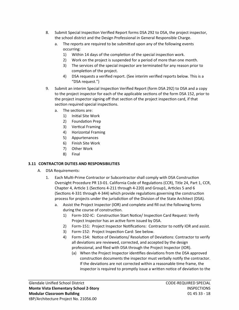
Glendale Unified School DistrictMonte Vista Elementary School 2-StoryModular Classroom BuildingtBP/Architecture Project No. 21056.00
CODE-REQUIRED SPECIALINSPECTIONS01 45 33 - 18
8. Submit Special Inspection Verified Report forms DSA 292 to DSA, the project inspector,the school district and the Design Professional in General Responsible Charge.a. The reports are required to be submitted upon any of the following events
occurring:1) Within 14 days of the completion of the special inspection work.2) Work on the project is suspended for a period of more than one month.3) The services of the special inspector are terminated for any reason prior to
completion of the project.4) DSA requests a verified report. (See interim verified reports below. This is a
“DSA request.”)
9. Submit an interim Special Inspection Verified Report (form DSA 292) to DSA and a copyto the project inspector for each of the applicable sections of the form DSA 152, prior tothe project inspector signing off that section of the project inspection card, if thatsection required special inspections.a. The sections are:
1) Initial Site Work2) Foundation Prep3) Vertical Framing4) Horizontal Framing5) Appurtenances6) Finish Site Work7) Other Work8) Final
3.11 CONTRACTOR DUTIES AND RESPONSIBILITIES
A. DSA Requirements:
1. Each Multi-Prime Contractor or Subcontractor shall comply with DSA ConstructionOversight Procedure PR 13-01. California Code of Regulations (CCR), Title 24, Part 1, CCR,Chapter 4, Article 1 (Sections 4-211 through 4-220) and Group1, Articles 5 and 6(Sections 4-331 through 4-344) which provide regulations governing the constructionprocess for projects under the jurisdiction of the Division of the State Architect (DSA).a. Assist the Project Inspector (IOR) and complete and fill out the following forms
during the course of construction.1) Form-102-IC: Construction Start Notice/ Inspection Card Request: Verify
Project Inspector has an active form issued by DSA.2) Form-151: Project Inspector Notifications: Contractor to notify IOR and assist.3) Form-152: Project Inspection Card: See below.4) Form-154: Notice of Deviations/ Resolution of Deviations: Contractor to verify
all deviations are reviewed, corrected, and accepted by the designprofessional, and filed with DSA through the Project Inspector (IOR).(a) When the Project Inspector identifies deviations from the DSA approved
construction documents the inspector must verbally notify the contractor.If the deviations are not corrected within a reasonable time frame, theinspector is required to promptly issue a written notice of deviation to the

Glendale Unified School DistrictMonte Vista Elementary School 2-StoryModular Classroom BuildingtBP/Architecture Project No. 21056.00
CODE-REQUIRED SPECIALINSPECTIONS01 45 33 - 19
contractor, with a copy sent to the design professional in generalresponsible charge and the DSA.
(b) When the noticed deviations are corrected, the inspector is required topromptly issue a written notice of resolution to the contractor, with acopy sent to the design professional in general responsible charge and theDSA.
(c) Deviations include both construction deviations and material deficiencies.(d) The written notice of deviations shall be made using form DSA 154.(e) The notice of resolution of deviations shall be made using the original
form DSA 154 that reported the deviations.5) Form-156: Commencement/Completion of Work Notification6) Form-6.C: Verified Report – Contractor: From each contractor having a
contract with the school board.
2. Duties of Contractor related to the use of form DSA 152 are as follows:a. The Contractor shall carefully study the DSA approved documents and shall plan a
schedule of operations well ahead of time.b. If at any time it is discovered that work is being done which is not in accordance
with the DSA approved construction documents, the Contractor shall correct thework immediately.
c. Verify that forms DSA 152 are issued for the project prior to the commencement ofconstruction.
d. Meet with the design team, the Laboratory of Record and the Project Inspector tomutually communicate and understand the testing and inspection program and themethods of communication appropriate for the project.
e. Notify the Project Inspector, in writing, of the commencement of construction ofeach and every aspect of the work at least 48 hours in advance by submitting formDSA 156 (or other agreed upon written documents) to the Project Inspector.
f. Notify the Project Inspector of the completion of construction of each and everyaspect of the work by submitting form DSA 156 (or other agreed upon writtendocuments) to the Project Inspector.
g. Consider the relationship of the signed off blocks and sections of the form DSA 152and the commencement of subsequent work. Until the Project Inspector has signedoff applicable blocks and sections of the form DSA 152, the Contractor may beprohibited from proceeding with subsequent construction activities that cover upthe unapproved work. Any subsequent construction activities, that cover up theunapproved work, will be subject to a “Stop Work Order” from the DSA or thedistrict and are subject to removal and remediation if found to be innon-compliance with the DSA approved construction documents.
h. Submit the final verified report. All prime contractors are required to submit finalContractor Verified Reports (form DSA 6-C) to DSA and the project inspector.1) The reports are required to be submitted upon any of the following events
occurring:(a) The project is substantially complete. DSA considers the project to be
complete when the construction is sufficiently complete in accordance
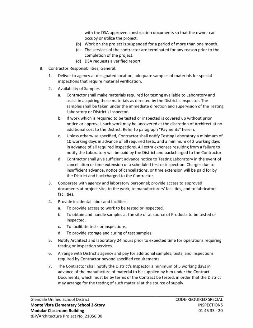
Glendale Unified School DistrictMonte Vista Elementary School 2-StoryModular Classroom BuildingtBP/Architecture Project No. 21056.00
CODE-REQUIRED SPECIALINSPECTIONS01 45 33 - 20
with the DSA approved construction documents so that the owner canoccupy or utilize the project.
(b) Work on the project is suspended for a period of more than one month.(c) The services of the contractor are terminated for any reason prior to the
completion of the project.(d) DSA requests a verified report.
B. Contractor Responsibilities, General:
1. Deliver to agency at designated location, adequate samples of materials for specialinspections that require material verification.
2. Availability of Samplesa. Contractor shall make materials required for testing available to Laboratory and
assist in acquiring these materials as directed by the District's Inspector. Thesamples shall be taken under the immediate direction and supervision of the TestingLaboratory or District's Inspector.
b. If work which is required to be tested or inspected is covered up without priornotice or approval, such work may be uncovered at the discretion of Architect at noadditional cost to the District. Refer to paragraph "Payments" herein.
c. Unless otherwise specified, Contractor shall notify Testing Laboratory a minimum of10 working days in advance of all required tests, and a minimum of 2 working daysin advance of all required inspections. All extra expenses resulting from a failure tonotify the Laboratory will be paid by the District and backcharged to the Contractor.
d. Contractor shall give sufficient advance notice to Testing Laboratory in the event ofcancellation or time extension of a scheduled test or inspection. Charges due toinsufficient advance, notice of cancellations, or time extension will be paid for bythe District and backcharged to the Contractor.
3. Cooperate with agency and laboratory personnel; provide access to approveddocuments at project site, to the work, to manufacturers' facilities, and to fabricators'facilities.
4. Provide incidental labor and facilities:a. To provide access to work to be tested or inspected.b. To obtain and handle samples at the site or at source of Products to be tested or
inspected.c. To facilitate tests or inspections.d. To provide storage and curing of test samples.
5. Notify Architect and laboratory 24 hours prior to expected time for operations requiringtesting or inspection services.
6. Arrange with District's agency and pay for additional samples, tests, and inspectionsrequired by Contractor beyond specified requirements.
7. The Contractor shall notify the District's Inspector a minimum of 5 working days inadvance of the manufacture of material to be supplied by him under the ContractDocuments, which must be by terms of the Contract be tested, in order that the Districtmay arrange for the testing of such material at the source of supply.

Glendale Unified School DistrictMonte Vista Elementary School 2-StoryModular Classroom BuildingtBP/Architecture Project No. 21056.00
CODE-REQUIRED SPECIALINSPECTIONS01 45 33 - 21
8. Material shipped by the Contractor from the source of supply before having satisfactorilypassed such testing and inspection or before the receipt of notice from said Inspectorthat such testing and inspection will not be required, shall not be incorporated in theProject.
9. The District will select and pay testing laboratory costs for all tests and inspections, butmay be reimbursed by the Contractor for such costs under the Contract conditions. Anydirect payments by the Contractor to the testing laboratory on this project is prohibited.
C. Contractor shall submit a written statement of responsibility to comply with CBC section1704A.4.
1. Each contractor responsible for the construction of a main wind- orseismic-force-resisting system, designated seismic system or a wind- or seismic-resistingcomponent listed in the statement of special inspections shall submit a writtenstatement of responsibility to the building official and the owner prior to thecommencement of work on the system or component. The contractor’s statement ofresponsibility shall contain the following:a. Acknowledgment of awareness of the special requirements contained in the
statement of special inspections;b. Acknowledgment that control will be exercised to obtain conformance with the
construction documents approved by the building official;c. Procedures for exercising control within the contractor’s organization, the method
and frequency of reporting and the distribution of the reports; andd. Identification and qualifications of the person(s) exercising such control and their
position(s) in the organization.
D. Contractor Responsibilities, Seismic Force-Resisting System, Designated Seismic System, andSeismic Force-Resisting Component: Submit written statement of responsibility for each itemlisted in the Statement of Special Inspections to AHJ and District prior to starting work. Statement of responsibility shall acknowledge awareness of special constructionrequirements and other requirements listed.
E. Contractor Responsibilities, Wind Force-Resisting System and Wind Force-ResistingComponent: Submit written statement of responsibility for each item listed in the Statementof Special Inspections to AHJ and District prior to starting work. Statement of responsibilityshall acknowledge awareness of special construction requirements and other requirementslisted.
F. Unless otherwise directed, materials not conforming to the requirements of ContractDocuments shall be promptly removed from the Project site.
3.12 MANUFACTURERS' AND FABRICATORS' FIELD SERVICES
A. When specified in individual specification sections, require material suppliers, assemblyfabricators, or product manufacturers to provide qualified staff personnel to observe siteconditions, conditions of surfaces and installation, quality of workmanship, start-up ofequipment, to test, adjust, and balance equipment as applicable, and to initiate instructionswhen necessary.
B. Submit qualifications of observer to Architect 30 days in advance of required observations.
1. Observer subject to approval of Architect.

Glendale Unified School DistrictMonte Vista Elementary School 2-StoryModular Classroom BuildingtBP/Architecture Project No. 21056.00
CODE-REQUIRED SPECIALINSPECTIONS01 45 33 - 22
2. Observer subject to approval of District.
C. Report observations and site decisions or instructions given to applicators or installers thatare supplemental or contrary to manufacturers' written instructions.
END OF SECTION

Glendale Unified School DistrictMonte Vista Elementary School 2-StoryModular Classroom BuildingtBP/Architecture Project No. 21056.00
TEMPORARY FACILITIES ANDCONTROLS
01 50 00 - 1
SECTION 01 50 00TEMPORARY FACILITIES AND CONTROLS
PART 1 GENERAL
1.01 SECTION INCLUDES
A. Temporary sanitary facilities.
B. Temporary Controls: enclosures and fencing.
C. Waste removal facilities and services.
D. Project identification sign.
1.02 RELATED REQUIREMENTS
A. Section 01 35 53 - Security Procedures
1.03 REFERENCE STANDARDS
1.04 TEMPORARY UTILITIES
A. Provide and pay for all electrical power, lighting, and water required for constructionpurposes.
B. Existing facilities may not be used.
C. Use trigger-operated nozzles for water hoses, to avoid waste of water.
1.05 TEMPORARY SANITARY FACILITIES
A. Provide and maintain required facilities and enclosures. Provide at time of projectmobilization.
1. Provide temporary toilet facilities if maximum number of personnel on project is greaterthan 10.
2. Submit proposed location of temporary toilet(s) to Construction Manager for approval.a. Place on-site portable toilets away from building air intakes and entryway.
B. Maintain daily in clean and sanitary condition.
1.06 FENCING
A. Construction: Contractor's option.
B. Provide 6 foot high fence around construction site; equip with vehicular and pedestrian gateswith locks.
1.07 SECURITY
A. Coordinate with District's security program.
1.08 CAFETERIA AND FOOD
A. Construction personnel shall police their own areas. All cups, cans, paper, wrappers, anddiscarded food must be placed in trash receptacles at end of each break.
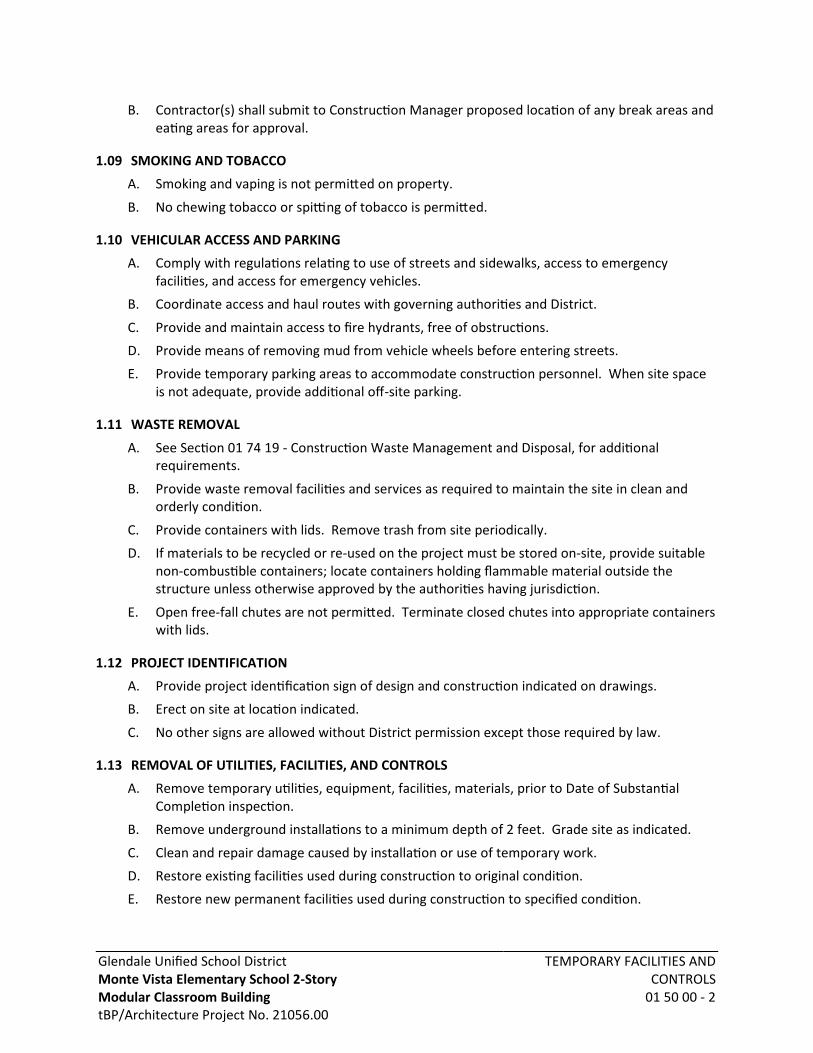
Glendale Unified School DistrictMonte Vista Elementary School 2-StoryModular Classroom BuildingtBP/Architecture Project No. 21056.00
TEMPORARY FACILITIES ANDCONTROLS
01 50 00 - 2
B. Contractor(s) shall submit to Construction Manager proposed location of any break areas andeating areas for approval.
1.09 SMOKING AND TOBACCO
A. Smoking and vaping is not permitted on property.
B. No chewing tobacco or spitting of tobacco is permitted.
1.10 VEHICULAR ACCESS AND PARKING
A. Comply with regulations relating to use of streets and sidewalks, access to emergencyfacilities, and access for emergency vehicles.
B. Coordinate access and haul routes with governing authorities and District.
C. Provide and maintain access to fire hydrants, free of obstructions.
D. Provide means of removing mud from vehicle wheels before entering streets.
E. Provide temporary parking areas to accommodate construction personnel. When site spaceis not adequate, provide additional off-site parking.
1.11 WASTE REMOVAL
A. See Section 01 74 19 - Construction Waste Management and Disposal, for additionalrequirements.
B. Provide waste removal facilities and services as required to maintain the site in clean andorderly condition.
C. Provide containers with lids. Remove trash from site periodically.
D. If materials to be recycled or re-used on the project must be stored on-site, provide suitablenon-combustible containers; locate containers holding flammable material outside thestructure unless otherwise approved by the authorities having jurisdiction.
E. Open free-fall chutes are not permitted. Terminate closed chutes into appropriate containerswith lids.
1.12 PROJECT IDENTIFICATION
A. Provide project identification sign of design and construction indicated on drawings.
B. Erect on site at location indicated.
C. No other signs are allowed without District permission except those required by law.
1.13 REMOVAL OF UTILITIES, FACILITIES, AND CONTROLS
A. Remove temporary utilities, equipment, facilities, materials, prior to Date of SubstantialCompletion inspection.
B. Remove underground installations to a minimum depth of 2 feet. Grade site as indicated.
C. Clean and repair damage caused by installation or use of temporary work.
D. Restore existing facilities used during construction to original condition.
E. Restore new permanent facilities used during construction to specified condition.
Glendale Unified School DistrictMonte Vista Elementary School 2-StoryModular Classroom BuildingtBP/Architecture Project No. 21056.00
TEMPORARY FACILITIES ANDCONTROLS
01 50 00 - 3
PART 2 PRODUCTS - NOT USED
PART 3 EXECUTION - NOT USED
END OF SECTION
Glendale Unified School District Monte Vista Elementary School 2-Story Modular Classroom Building tBP/Architecture Project No. 21056.00
TEMPORARY STORM WATER
POLLUTION CONTROL
01 57 23 - 1
SECTION 01 57 23
TEMPORARY STORM WATER POLLUTION CONTROL PART 1 - GENERAL 1.1 The Contractor shall exercise every reasonable precaution to protect channels, storm drains,
and bodies of water from pollution.
A. Conduct and schedule operations to minimize or avoid muddying and silting channels, drains, and waters.
B. As required, obtain permits for erosion and water pollution control from the
appropriate jurisdictional agency before starting Work.
C. Provide any necessary water pollution control devices to prevent, control, and abate water pollution, and implement good housekeeping pollution control measures to reduce the discharge of pollutants from work sites to the maximum extent practicable. These water pollution control devices include drains, gutters, slope protection blankets and retention basins and shall be constructed concurrently with other Work at the earliest practicable time.
D. Exercise care in preserving vegetation and protecting property, to avoid disturbing areas
beyond the limits of the Work. Promptly repair any damage caused by Contractor operations.
E. Comply with the specific requirements based on acreage of disturbed soil.
F. Penalties: Failure to comply with this Section may result in significant fines and possible
imprisonment. The RWQCB or other prosecuting authority may assess fines of up to $32,500 per day for each violation. Should the Owner be fined or penalized as a result of the Contractor failing to comply with this Section, the Contractor shall reimburse the Owner for any and all fines, penalties and related costs.
G. Notification and Report: If pollution occurs in the work area for any reason or when the
Contractor becomes aware of any violation of this Section, correct the problem and immediately notify the Inspector. In addition, submit a written report to the Engineer within seven (7) calendar days describing the incident and the corrective actions taken. If either the Inspector or Engineer is first to observe pollution or a violation, the Contractor shall also explain in the written report why the Work was inadequately monitored.
H. The provisions of this Section describe minimum compliance and do not preclude other
more stringent stormwater pollution control measures that may be required in the Contract.
Glendale Unified School District Monte Vista Elementary School 2-Story Modular Classroom Building tBP/Architecture Project No. 21056.00
TEMPORARY STORM WATER
POLLUTION CONTROL
01 57 23 - 2
1.2 DEFINITIONS
A. “Construction activity": Operations such as clearing, grading, disturbances to the ground such as stockpiling, or excavation that results in soil disturbances. If construction activity is part of a larger common plan of development, the amount of disturbed soil is the total land area of disturbed soil that results under the common plan.
1.3 LIABILITIES & PENALTIES:
A. Payment of penalties for non-compliance by CONTRACTOR shall be the sole responsibility of CONTRACTOR.
B. Compliance with the Clean Water Act pertaining is the sole responsibility of
CONTRACTOR. Any fine against OWNER due to non-compliance by CONTRACTOR, OWNER shall recover all costs of the fine by appropriate OWNER Assessment.
PART 2 - EXECUTION 2.1 Construction activity: Comply with the following minimum water quality protection
requirements.
A. Retain eroded sediments and other pollutants on-site and do not allow transportation from the site by sheet flow, swales, area drains, natural drainage, or wind. Control slope and channel erosion by implementing an effective combination of best management practices (BMPs). Such BMPs include scheduling grading during non-rainy seasons, planting and maintaining vegetation on slopes and covering erosion-susceptible slopes.
B. Protect stockpiles of earth and other construction-related materials from being
transported from the site by wind or water.
C. Properly store and handle fuels, oils, solvents, and other toxic materials to not contaminate the soil or surface waters, enter the groundwater, or be placed where they may enter a live stream, channel, drain, or other water conveyance facility. Protect all approved toxic storage containers from weather. Clean spills immediately and properly dispose of cleanup materials. Spills shall not be washed into live streams, channels, drains, or other water conveyance facilities. IF RAIN OR STORM WATER RUN OFF COMES IN CONTACT WITH POLLUTANTS (SUCH AS SOIL STABILIZERS, PAINT OR FLUID FROM VEHICLES) REPORT TO INSPECTOR IMMEDIATELY. CONTRACTOR WILL BE REQUIRED TO SAMPLE AND REMEDIATE CONTAMINATED WATER.
D. Do not wash excess or waste concrete into the public way or any drainage system.
Retain concrete wastes on-site until they can be appropriately disposed of or recycled.
E. Deposit trash and construction-related solid wastes in covered receptacles to prevent contamination of rainwater and dispersal by wind.

Glendale Unified School District Monte Vista Elementary School 2-Story Modular Classroom Building tBP/Architecture Project No. 21056.00
TEMPORARY STORM WATER
POLLUTION CONTROL
01 57 23 - 3
F. Do not allow sediments and other materials to be tracked from the site by vehicle traffic. Stabilize construction entrance roadways to inhibit sediments from being deposited onto public ways. Immediately sweep up accidental depositions. Do not allow depositions to be washed away by rain or by any other means.
G. Contain non-stormwater runoff from equipment or vehicle washing and any other
activity at the work site.
H. At completion of the Work, clear the worksite of debris and restore to a condition at least equal to or better than prior to construction.
PART 3 – MAINTENANCE 3.1 To ensure the proper implementation and functioning of control measures, the Contractor shall
regularly inspect and maintain the construction site. The Contractor shall identify corrective actions and time needed to address any deficient measures or reinitiate any measures that have been discontinued. Inspections of the construction site shall be conducted by the Contractor to identify deficient measures, as follows: 1. Prior to a forecast storm;
2. At 24-hour intervals during extended precipitation events; 3. After all precipitation, which causes runoff capable of carrying sediment from
the construction site; and; 4. Routinely, at a minimum of once every week during the rainy season (October
1st – April 30th) and once every month during non-rainy season (May 1st – September 30th).
3.2 All temporary and/or permanent post-construction control measures shall be maintained and
regularly inspected by the Contractor after all improvements are in place and accepted by the Owner. Temporary and/or permanent post-construction landscaping maintenance shall include but not limited to, watering, seeding, hydro-seeding, matting, slope stabilization, re-vegetation, and any other maintenance control measures recommended by the Owner to insure proper erosion control and plant growth.
END OF SECTION
Glendale Unified School DistrictMonte Vista Elementary School 2-StoryModular Classroom BuildingtBP/Architecture Project No. 21056.00
TEMPORARY PROJECT SIGNAGE01 58 13 - 1
SECTION 01 58 13TEMPORARY PROJECT SIGNAGE
PART 1 GENERAL
1.01 SECTION INCLUDES
A. Project identification sign.
B. Project informational signs.
1.02 RELATED REQUIREMENTS
A. Section 01 10 00 - Summary: Responsibility to provide signs.
B. Section 05 50 00 - Metal Fabrications: Miscellaneous connectors.
C. Section 06 10 00 - Rough Carpentry: General requirements for structural and non-structuralrough carpentry Work.
D. Section 09 91 13 - Exterior Painting: General requirements for paint products and painting.
1.03 REFERENCE STANDARDS
A. FHWA (SHS) - Standard Highway Signs and Markings.
1.04 QUALITY ASSURANCE
A. Design sign and structure to withstand 80 miles/hr wind velocity.
B. Sign Painter: Experienced as a professional sign painter for minimum three years.
1. Sign painter shall be regularly engaged and specializing in the design, execution,construction and installation of exterior signage of equivalent type, size and complexityas those required for Project.
C. Finishes, Painting: Adequate to withstand weathering, fading, and chipping for duration ofconstruction.
1.05 SUBMITTALS
A. See Section 01 30 00 - Administrative Requirements for submittal procedures.
B. Shop Drawing: Show content, layout, lettering, color, foundation, structure, sizes and gradesof members.
PART 2 PRODUCTS
2.01 SIGN MATERIALS
A. Structure and Framing: New, wood, structurally adequate to support sign panel and suitablefor specified finish.
B. Sign Surfaces: Exterior grade plywood with medium or high density phenolic sheet overlay,minimum 3/4 inch thick, standard large sizes to minimize joints. Provide sheet thickness asrequired to span across framing members and provide even, smooth surface without wavesor buckles.

Glendale Unified School DistrictMonte Vista Elementary School 2-StoryModular Classroom BuildingtBP/Architecture Project No. 21056.00
TEMPORARY PROJECT SIGNAGE01 58 13 - 2
C. Rough Hardware: Galvanized steel, as specified in Section 05 50 00 - Metal Fabrications andSection 06 10 00 - Rough Carpentry..
D. Sign Face Paint and Primers: Exterior quality, primer, two gloss enamel finish coats; signbackground of color as selected. Provide paint type as customarily used for sign painting,adequate to resist weathering and fading for the scheduled construction period.
E. Sign Structure Paint and Primers: Exterior quality, primer, one gloss enamel finish coats; coloras selected. Provide paint type as customarily used for sign painting, adequate to resistweathering and fading for the scheduled construction period.
F. Lettering: Exterior quality paint, colors as selected.
2.02 PROJECT IDENTIFICATION SIGN
A. Provide painted sign of construction, design, and content shown on Drawings, locationdesignated or agreed to by Architect.
1. Graphic design, text, style of lettering, and colors shall be as directed; assume 4 colorsand special graphic for Project title.
B. Content:
1. Project number, title, logo and name of District as indicated on Contract Documents.
2. Include organizational logos of parties identified on sign.
3. Names and titles of authorities.
4. Names and titles of Architect and Consultants.
5. Name of Prime Contractor and major Subcontractors.
C. Graphic Design, Colors, Style of Lettering: Designated by Architect.
1. Sign Painting: Sign panels shall be shop painted and field installed.a. Sign painting shall be performed by professional sign painters. Silk screen method is
recommended in order to accurately depict graphics.b. Paint back and edges of sign panels for complete weather resistance and finished
appearance.
D. Project Address Signs: Provide Project name and street address signs, minimum of 4 feetwide, to identify Project to facilitate deliveries.
1. Graphic design and colors shall match Project Identification Sign.
2. Text shall be as directed.
E. Lettering: Standard Alphabet Series C, as specified in FHWA (SHS).
2.03 PROJECT INFORMATIONAL SIGNS
A. Restrictions: Signs other than Project Identification Sign specified above and ProjectInformational Signs specified below shall not be displayed without approval of Architect.
B. Project Informational Signs: Informational signs, necessary for conduct of constructionactivities or required by governmental authorities having jurisdiction may be displayed whenin conformance to sign construction and graphic requirements specified in this Section.
1. Architect may review such signs. If so, review will be for sign construction, and graphicdesigns only.
Glendale Unified School DistrictMonte Vista Elementary School 2-StoryModular Classroom BuildingtBP/Architecture Project No. 21056.00
TEMPORARY PROJECT SIGNAGE01 58 13 - 3
2. Adequacy of signage for safety and conformance to requirements of authorities havingjurisdiction and trade practices shall be solely Contractor's responsibility.
C. Painted informational signs of same colors and lettering as Project Identification sign, orstandard products; size lettering to provide legibility at 100 foot distance.
1. Colors shall be as required by authorities having jurisdiction and, if not otherwiserequired, of colors consistent with Project graphics.
2. Informational signage shall be produced by professional sign painters and be of size andlettering style consistent with use.
D. Provide at each field office, storage shed, and directional signs to direct traffic into and withinsite. Relocate as Work progress requires.
E. Provide municipal traffic agency directional traffic signs to and within site.
PART 3 EXECUTION
3.01 INSTALLATION
A. Install project identification sign within 30 days after date fixed by Notice to Proceed.
B. Erect at location of high public visibility adjacent to main entrance to site.
C. Erect supports and framing on secure foundation, rigidly braced and framed to resist windloadings.
D. Install sign surface plumb and level, with butt joints. Anchor securely.
E. Paint exposed surfaces and edges of sign, supports, and framing for a finished appearance.
F. Project Identification Sign Installation
1. Construction: Construct sign support structure and install panels in durable manner, toresist high winds.
2. Installation: Erect Sign on site at a lighted location of high public visibility, adjacent tothe main entrance to the site, as approved by Architect.a. Install sign at height for optimum visibility, on ground-mounted poles or attached to
portable structure on skids.b. Portable structure shall resist overturning force of wind.
3. Street Address Signs: Locate and install signs at each access point from public streets.
G. Project Informational Signs Installation:
1. Construction: Construct sign support structure and install panels in durable manner, toresist high winds.
2. Project Informational Signs Installation:a. Locate signs as necessary for construction activities and as required by authorities
having jurisdiction.b. Install informational signs for optimum visibility, on ground-mounted posts or
temporarily attached to surfaces of structures.c. Attachment methods shall leave no permanent disfiguration or discoloration on
completed Work.

Glendale Unified School DistrictMonte Vista Elementary School 2-StoryModular Classroom BuildingtBP/Architecture Project No. 21056.00
TEMPORARY PROJECT SIGNAGE01 58 13 - 4
3.02 MAINTENANCE
A. Maintain signs and supports neat clean condition. Repair all deterioration, weathering anddamage to structure framing, and signage.
B. Sign Relocation: Relocate signs as required by progress of the Work.
3.03 REMOVAL
A. Remove signs, framing, supports, and foundations at completion of Project and restore thearea prior to Substantial Completion review.
END OF SECTION
Glendale Unified School DistrictMonte Vista Elementary School 2-StoryModular Classroom BuildingtBP/Architecture Project No. 21056.00
PRODUCT REQUIREMENTS01 60 00 - 1
SECTION 01 60 00PRODUCT REQUIREMENTS
PART 1 GENERAL
1.01 SECTION INCLUDES
A. General product requirements.
1. System Completeness.
2. Installation of Products.
B. Transportation, handling, storage and protection.
C. Product option requirements.
D. Substitution limitations.
E. Procedures for District-supplied products.
F. Maintenance materials, including extra materials, spare parts, tools, and software.
1.02 RELATED REQUIREMENTS
A. Section 01 10 00 - Summary: Identification of District-supplied products.
B. Section 01 25 00 - Substitution Procedures: Substitutions made during procurement and/orconstruction phases.
C. Section 01 40 00 - Quality Requirements: Product quality monitoring.
D. Section 01 61 16 - Volatile Organic Compound (VOC) Content Restrictions: Requirements forVOC-restricted product categories.
E. Section 01 74 19 - Construction Waste Management and Disposal: Waste disposalrequirements potentially affecting product selection, packaging and substitutions.
F. Divisions 31 - 33: Sitework.
1.03 REFERENCE STANDARDS
A. CAL (CDPH SM) - Standard Method for the Testing and Evaluation of Volatile Organic ChemicalEmissions From Indoor Sources Using Environmental Chambers.
B. NFPA 70 - National Electrical Code.
1. Use California Electrical Code.
1.04 SUBMITTALS
A. Proposed Products List: Submit list of major products proposed for use, with name ofmanufacturer, trade name, and model number of each product.
1. Submit within 15 days after date of Agreement.
2. For products specified only by reference standards, list applicable reference standards.
B. Product Data Submittals: Submit manufacturer's standard published data. Mark each copy toidentify applicable products, models, options, and other data. Supplement manufacturers'standard data to provide information specific to this Project.

Glendale Unified School DistrictMonte Vista Elementary School 2-StoryModular Classroom BuildingtBP/Architecture Project No. 21056.00
PRODUCT REQUIREMENTS01 60 00 - 2
C. Shop Drawing Submittals: Prepared specifically for this Project; indicate utility and electricalcharacteristics, utility connection requirements, and location of utility outlets for service forfunctional equipment and appliances.
D. Sample Submittals: Illustrate functional and aesthetic characteristics of the product, withintegral parts and attachment devices. Coordinate sample submittals for interfacing work.
1. For selection from standard finishes, submit samples of the full range of themanufacturer's standard colors, textures, and patterns.
1.05 QUALITY ASSURANCE
A. CAL (CDPH SM) v1.1: California Department of Public Health (CDPH) Standard Method for theTesting and Evaluation of Volatile Organic Chemical Emissions from Indoor Sources UsingEnvironmental Chambers, v. 1.1–2010, for the emissions testing and requirements ofproducts and materials.
PART 2 PRODUCTS
2.01 GENERAL REQUIREMENTS
A. Drawings and Specifications:
1. If a conflict exists between the Drawings and the Specifications (Project Manual), thenthe Contractor is to submit a Request for Interpretation from the Architect.a. As noted in the General Conditions, the more stringent requirements govern,
including cost of materials and/or installation.
2. If a specific product is indicated on the Drawings for use, then that product is to be usedwithout exception in the location identified.
3. If the Contractor proposes the use of another product other than the item indicated,whether or not listed in these specifications, Contractor is to submit the product usingthe complete substitution process. See the the Article titled "SUBSTITUTIONS".
4. DSA (Division of the State Architect) approval is also required prior to the use orinstallation of any substitution, on any product or location of product (requiring arevision to the Drawings or Specifications), included in these construction documents.a. Installation of a non-approved product may result in the Contractor removing and
replacing the non-approved product at the Contractor's own expense.
B. General: Items purchased for incorporation in the Work, whether purchased for the Projector taken from previously purchased stock, and include materials, equipment, assemblies,fabrications and systems.
1. Named Products: Items identified by manufacturer's product name, including make ormodel designations indicated in the manufacturer's published product data.
2. Materials: Products that are shaped, cut, worked, mixed, finished, refined or otherwisefabricated, processed or installed to form a part of the Work.
3. Equipment: A product with operating parts, whether motorized or manually operated,that requires connections such as wiring or piping.

Glendale Unified School DistrictMonte Vista Elementary School 2-StoryModular Classroom BuildingtBP/Architecture Project No. 21056.00
PRODUCT REQUIREMENTS01 60 00 - 3
C. Specific Product Requirements: Refer to requirements of Section 01 40 00 - QualityRequirements and individual product technical Sections for specific requirements forproducts.
D. Minimum Requirements: Specified requirements for products are minimum requirements. Refer to general requirements for quality of the Work specified in Section 01 40 00 - QualityRequirements and elsewhere herein.
E. Standard Products:
1. Where specific products are not specified, provide standard products of types and kindsthat are suitable for the intended purposes and that are usually and customarily used onsimilar projects under similar conditions.
2. Products shall be as selected by Contractor and subject to review and acceptance by theDistrict and Architect.
F. Product Completeness:
1. Provide products complete with all accessories, trim, finish, safety guards and otherdevices and details needed for a complete installation and for the intended use andeffect.
2. Comply with additional requirements specified herein in Article titled "SYSTEMCOMPLETENESS".
G. Code Compliance:
1. All products, other than commodity products prescribed by Code, are to have a currentICC Evaluation Service Research Report (ICC ESR), CABO National Evaluation Report(NER), or other testing agencies as accepted by the Division of the State Architect.
2. Refer to additional requirements specified in Section 01 41 00 - RegulatoryRequirements.
2.02 SYSTEM COMPLETENESS
A. The Contract Drawings and Specifications are not intended to be comprehensive directions onhow to produce the Work. Rather, the Drawings and Specifications are instruments of serviceprepared to describe the design intent for the completed Work.
B. It is intended that all equipment, systems and assemblies be complete and fully functionaleven though not fully described. Provide all products and operations necessary to achieve thedesign intent described in the Contract Documents.
C. Refer to related general requirements specified in Section 01 41 00 - RegulatoryRequirements regarding compliance with minimum requirements of applicable codes,ordinances and standards.
D. Omissions and Misdescriptions: Contractor shall report to Architect immediately whenelements essential to proper execution of the Work are discovered to be missing ormisdescribed in the Drawings and Specifications or if the design intent is unclear.
1. Should an essential element be discovered as missing or misdescribed prior to receipt ofBids, an Addendum will be issued so that all costs may be accounted for in the ContractSum.

Glendale Unified School DistrictMonte Vista Elementary School 2-StoryModular Classroom BuildingtBP/Architecture Project No. 21056.00
PRODUCT REQUIREMENTS01 60 00 - 4
2. Should an obvious omission or misdescription of a necessary element be discovered andreported after execution of the Agreement, Contractor shall provide the element asthough fully and correctly described, and a no-cost Change Order shall be executed.
3. Refer to related General Requirements specified in Section 01 30 00 - AdministrativeRequirements and 01 31 14 - Facility Services Coordination regarding constructioninterfacing and coordination.
2.03 NEW PRODUCTS
A. Provide new products unless specifically required or permitted by Contract Documents.
1. Provide products that fully comply with the Contract Documents, are undamaged andunused at installation.
2. Comply with additional requirements specified herein in Article titled "PRODUCTOPTIONS".
B. See Section 01 40 00 - Quality Requirements, for additional source quality controlrequirements.
C. Use of products having any of the following characteristics is not permitted:
1. Made outside the United States, its territories, Canada, or Mexico.
2. Containing lead, cadmium, or asbestos.
D. Where other criteria are met, Contractor shall give preference to products that:
1. If used on interior, have lower emissions, as defined in Section 01 61 16.
2. If wet-applied, have lower VOC content, as defined in Section 01 61 16.
3. Are extracted, harvested, and/or manufactured closer to the location of the project.
4. Have longer documented life span under normal use.
5. Result in less construction waste. See Section 01 74 19
E. Provide interchangeable components of the same manufacture for components beingreplaced.
1. To the fullest extent possible, provide products of the same kind from a single source.Products required to be supplied in quantity shall be the same product andinterchangeable throughout the Work.
2. When options are specified for the selection of any of two or more products, provideproduct selected to be compatible with products previously selected.
F. Product Nameplates and Instructions:
1. Except for required Code-compliance labels and operating and safety instructions, locatenameplates on inconspicuous, accessible surfaces. Do not attach manufacturer'sidentifying nameplates or trademarks on surfaces exposed to view in occupied spaces orto the exterior.
2. Provide a permanent nameplate on each item of service-connected or power-operatedequipment. Nameplates shall contain identifying information and essential operatingdata such as the following example:a. Name of manufacturerb. Name of product
Glendale Unified School DistrictMonte Vista Elementary School 2-StoryModular Classroom BuildingtBP/Architecture Project No. 21056.00
PRODUCT REQUIREMENTS01 60 00 - 5
c. Model and serial numberd. Capacitye. Operating and Power Characteristicsf. Labels of Tested Compliance with Codes and Standards
3. Refer to additional requirements which may be specified in various sections, as includedin this Project Manual.
4. For each item of service-connected or power-operated equipment, provide operatingand safety instructions, permanently affixed and of durable construction, with legiblemachine lettering. Comply with all applicable requirements of authorities havingjurisdiction and listing agencies.
G. Wiring Terminations: Provide terminal lugs to match branch circuit conductor quantities,sizes, and materials indicated. Size terminal lugs to CEC/NFPA 70, include lugs for terminalbox.
H. Cord and Plug: Provide minimum 6 foot cord and plug including grounding connector forconnection to electric wiring system. Cord of longer length is specified in individualspecification sections.
2.04 PRODUCT OPTIONS
A. Unless the specifications state that no substitution is permitted, whenever the ContractDocuments indicate any specific article, device, equipment, product, material, fixture,patented process, form, method, or type of construction or any specific name, make, tradename, or catalog number, with or without the words "or equal," such specification shall bedeemed to be used for the purpose of facilitating description of the material, process, orarticle desired and shall be deemed to be followed by the words "or equal."
1. See Section 01 25 00 - Substitution Procedures.
B. Products Specified by Reference Standards or by Description Only: Use any product meetingthose standards or description.
1. Reference Standards:a. Where Specifications require compliance with a standard, provided product shall
fully comply with the standard specified.b. Refer to general requirements specified in Section 01 42 19 - Reference Standards
regarding compliance with referenced standards, standard specifications, codes,practices and requirements for products.
2. Product Description:a. Where Specifications describe a product, listing characteristics required, with or
without use of a brand name, provide a product that has the specified attributesand otherwise complies with specified requirements.
3. Performance Requirements:a. Where Specifications require compliance with performance requirements, provide
product(s) that comply and are recommended by the manufacturer for the intendedapplication.
b. Verification of manufacturer's recommendations may be by product literature or bycertification of performance from manufacturer.

Glendale Unified School DistrictMonte Vista Elementary School 2-StoryModular Classroom BuildingtBP/Architecture Project No. 21056.00
PRODUCT REQUIREMENTS01 60 00 - 6
C. Products Specified by Naming One or More Manufacturers with a Provision for Substitutions: Submit a request for substitution for any manufacturer not named.
D. Products Specified by Identification of Manufacturer and Product Name or Number:
1. "Specified Manufacturer": Provide the specified product(s) of the specifiedmanufacturer.a. If only one manufacturer is specified, without "acceptable manufacturers" being
identified, provide only the specified product(s) of the specified manufacturer.b. If District standard is indicated make all efforts to provide that product.c. If the phrase "or equal" or "approved equal" is stated or reference is made to the
"or equal provision," products of other manufacturers may be provided if suchproducts are equivalent to the specified product(s) of the specified manufacturer.1) Equivalence shall be demonstrated by submission of information in compliance
with requirements of Section 01 25 00 - Substitution Procedures.
2. "Acceptable Manufacturers":a. Product(s) of the named manufacturers, if equivalent to the specified product(s) of
the specified manufacturer, will be acceptable in accordance with the requirementsof Section 01 25 00 - Substitution Procedures.1) Exception: Considerations regarding changes in Contract Time and Contract
Sum will be waived if no increase in Contract Time or Contract Sum resultsfrom use of such equivalent products.
3. Unnamed manufacturers: Product(s) of unnamed manufacturers will be acceptablewhen disclosed during the bidding period and only as follows:a. Unless specifically stated that substitutions will not be accepted or considered, the
phrase "or equal" shall be assumed to be included in the description of specifiedproduct(s).
b. Equivalent products of unnamed manufacturers will be accepted in accordance withthe "or equal" provision specified herein, below.
c. If provided, products of unnamed manufacturers shall be subject to therequirements of Section 01 25 00 - Substitution Procedures.
4. Quality basis:a. Specified product(s) of the specified manufacturer shall serve as the basis by which
products by named acceptable manufacturers and products of unnamedmanufacturers will be evaluated.
b. Where characteristics of the specified product are described, where performancecharacteristics are identified or where reference is made to industry standards, suchcharacteristics are specified to identify the most significant attributes of thespecified product(s) which will be used to evaluate products of othermanufacturers.
E. Products Specified by Combination of Methods: Where products are specified by acombination of attributes, including manufacturer's name, product brand name, productcatalog or identification number, industry reference standard, or description of productcharacteristics, provide products conforming to all specified attributes.

Glendale Unified School DistrictMonte Vista Elementary School 2-StoryModular Classroom BuildingtBP/Architecture Project No. 21056.00
PRODUCT REQUIREMENTS01 60 00 - 7
F. "Or Equal" Provision: Where the phrase "or equal" or the phrase "or approved equal" isincluded, equivalent product(s) of unnamed manufacturer(s) may be provided as specifiedabove in subparagraph titled "Unnamed manufacturers" and Section 01 25 00 - SubstitutionProcedures with the following conditions:
1. The requirements of Section 01 25 00 - Substitution Procedures applies to productsprovided under the "or equal" provision.a. Exception: If the proposed product(s) are determined to be equivalent to the
specified product(s) of the specified manufacturer, the requirement specified forsubstitutions to result in a net reduction in Contract Time or Contract Sum will bewaived.
2. Use of product(s) under the "or equal" provision shall not result in any delay incompletion of the Work, including completion of portions of the Work for use by Districtor for work under separate contract by District.
3. Use of product(s) under the "or equal" provision shall not result in any costs to theDistrict, including design fees and permit and plan check fees.
4. Use of product(s) under the "or equal" provision shall not require substantial change inthe intent of the design, in the opinion of the Architect.a. The intent of the design shall include functional performance and aesthetic
qualities.
5. The determination of equivalence will be made by the Architect and District, and suchdetermination shall be final.
G. Visual Matching:
1. Where Specifications require matching a sample, the decision by the Architect onwhether a proposed product matches shall be final.
2. Where no product visually matches but the product complies with other requirements,comply with provisions for substitutions for selection of a matching product in anothercategory.
H. Visual Selection of Products:
1. Where requirements include the phrase "as selected from manufacturer's standardcolors, patterns and textures", or a similar phrase, selections of products will be made byindicated party or, if not indicated, by the Architect. The will select color, pattern andtexture from the product line of submitted manufacturer, if all other specified provisionsare met.
2. The Architect will select color, pattern and texture from the product line of submittedmanufacturer, if all other specified provisions are met.
2.05 MAINTENANCE MATERIALS
A. Furnish extra materials, spare parts, tools, and software of types and in quantities specified inindividual specification sections.
B. Deliver to Project site; obtain receipt prior to final payment.

Glendale Unified School DistrictMonte Vista Elementary School 2-StoryModular Classroom BuildingtBP/Architecture Project No. 21056.00
PRODUCT REQUIREMENTS01 60 00 - 8
PART 3 EXECUTION
3.01 SUBSTITUTION LIMITATIONS
A. See Section 01 25 00 - Substitution Procedures.
3.02 OWNER-SUPPLIED PRODUCTS
A. See Section 01 10 00 - Summary for identification of District-supplied products.
B. District's Responsibilities:
1. Arrange for and deliver District reviewed shop drawings, product data, and samples, toContractor.
2. Arrange and pay for product delivery to site.
3. On delivery, inspect products jointly with Contractor.
4. Submit claims for transportation damage and replace damaged, defective, or deficientitems.
5. Arrange for manufacturers' warranties, inspections, and service.
C. Contractor's Responsibilities:
1. Review District reviewed shop drawings, product data, and samples.
2. Receive and unload products at site; inspect for completeness or damage jointly withDistrict.
3. Handle, store, install and finish products.
4. Repair or replace items damaged after receipt.
3.03 TRANSPORTATION AND HANDLING
A. Package products for shipment in manner to prevent damage; for equipment, package toavoid loss of factory calibration.
B. If special precautions are required, attach instructions prominently and legibly on outside ofpackaging.
C. Coordinate schedule of product delivery to designated prepared areas in order to minimizesite storage time and potential damage to stored materials.
1. Schedule delivery to minimize long-term storage and prevent overcrowding constructionspaces.
2. Coordinate with installation to ensure minimum holding time for items that areflammable, hazardous, easily damaged, or sensitive to deterioration, theft and otherlosses.
D. Transport and handle products in accordance with manufacturer's instructions.
E. Transport products by methods to avoid product damage.
F. Transport materials in covered trucks to prevent contamination of product and littering ofsurrounding areas.
G. Promptly inspect shipments to ensure that products comply with requirements, quantities arecorrect, and products are undamaged.

Glendale Unified School DistrictMonte Vista Elementary School 2-StoryModular Classroom BuildingtBP/Architecture Project No. 21056.00
PRODUCT REQUIREMENTS01 60 00 - 9
H. Provide equipment and personnel to handle products by methods to prevent soiling,disfigurement, or damage, and to minimize handling.
I. Arrange for the return of packing materials, such as wood pallets, where economicallyfeasible.
3.04 STORAGE AND PROTECTION
A. Provide protection of stored materials and products against theft, casualty, or deterioration.
B. Designate receiving/storage areas for incoming products so that they are delivered accordingto installation schedule and placed convenient to work area in order to minimize waste due toexcessive materials handling and misapplication. See Section 01 74 19.
1. Structural Loading Limitations: Handle and store products and materials so as not toexceed static and dynamic load-bearing capacities of project floor and roof areas.
C. Inspection Provisions: Arrange storage to provide access for inspection and measurement ofquantity or counting of units.
D. Structural Considerations: Store heavy materials away from the structure in a manner thatwill not endanger supporting construction.
E. Store and protect products in accordance with manufacturers' instructions.
F. Store with seals and labels intact and legible.
G. Arrange storage of materials and products to allow for visual inspection for the purpose ofdetermination of quantities, amounts, and unit counts.
H. Store sensitive products in weathertight, climate-controlled enclosures in an environmentfavorable to product.
I. For exterior storage of fabricated products, place on sloped supports above ground.
1. Place products on raised blocks, pallets or other supports, above ground and in a mannerto not create ponding or misdirection of runoff.
J. Providebonded off-site storage and protection when site does not permit on-site storage orprotection.
K. Protect products from damage or deterioration due to construction operations, weather,precipitation, humidity, temperature, sunlight and ultraviolet light, dirt, dust, and othercontaminants.
1. Periodically inspect to ensure products are undamaged, and are maintained underrequired conditions.
2. Remove and replace products damaged by improper storage or protection with newproducts at no change in Contract Sum or Contract Time.
3. Weather-Resistant Storage:a. Store moisture-sensitive products above ground, under cover in a weathertight
enclosure or covered with an impervious sheet covering. Provide adequateventilation to avoid condensation.
b. Maintain storage within temperature and humidity ranges required bymanufacturer's instructions.
c. Store loose granular materials on solid surfaces in a well-drained area. Preventmixing with foreign matter.
Glendale Unified School DistrictMonte Vista Elementary School 2-StoryModular Classroom BuildingtBP/Architecture Project No. 21056.00
PRODUCT REQUIREMENTS01 60 00 - 10
L. Comply with manufacturer's warranty conditions, if any.
M. Do not store products directly on the ground.
N. Cover products subject to deterioration with impervious sheet covering. Provide ventilationto prevent condensation and degradation of products.
O. Store loose granular materials on solid flat surfaces in a well-drained area. Prevent mixingwith foreign matter.
P. Prevent contact with material that may cause corrosion, discoloration, or staining.
Q. Provide equipment and personnel to store products by methods to prevent soiling,disfigurement, or damage.
R. Arrange storage of products to permit access for inspection. Periodically inspect to verifyproducts are undamaged and are maintained in acceptable condition.
3.05 INSTALLATION OF PRODUCTS
A. Comply with manufacturer's instructions and recommendations for installation of products,except where more stringent requirements are specified, are necessary due to Projectconditions or are required by authorities having jurisdiction.
B. Anchor each product securely in place, accurately located and aligned with other Work.
C. Clean exposed surfaces and provide protection to ensure freedom from damage anddeterioration at time of Substantial Completion review. Refer to additional requirementsspecified in General Conditions, Section 01 50 00 - Temporary Construction Facilities andControls and 01 70 00 - Execution and Closeout Requirements.
3.06 PROTECTION OF COMPLETED WORK
A. Provide barriers, substantial coverings and notices to protect installed Work from traffic andsubsequent construction operations.
B. Remove protective measures when no longer required and prior to Substantial Completionreview of the Work.
C. Comply with additional requirements specified in Section 01 50 00 - Temporary ConstructionFacilities and Controls.
END OF SECTION
Glendale Unified School DistrictMonte Vista Elementary School 2-StoryModular Classroom BuildingtBP/Architecture Project No. 21056.00
VOLATILE ORGANIC COMPOUND(VOC) CONTENT RESTRICTIONS
01 61 16 - 1
SECTION 01 61 16VOLATILE ORGANIC COMPOUND (VOC) CONTENT RESTRICTIONS
PART 1 GENERAL
1.01 SECTION INCLUDES
A. Requirements for Indoor-Emissions-Restricted products.
B. Requirements for VOC-Content-Restricted products.
C. Requirement for installer certification that they did not use any non-compliant products.
1.02 RELATED REQUIREMENTS
A. Section 01 30 00 - Administrative Requirements: Submittal procedures.
B. Section 01 40 00 - Quality Requirements: Procedures for testing and certifications.
C. Section 01 60 00 - Product Requirements: Fundamental product requirements, substitutionsand product options, delivery, storage, and handling.
D. Section 07 92 00 - Joint Sealants: Emissions-compliant sealants.
1.03 DEFINITIONS
A. Indoor-Emissions-Restricted Products: All products in the following product categories,whether specified or not:
1. Interior paints and coatings applied on site.
2. Interior adhesives and sealants applied on site, including flooring adhesives.
3. Flooring.
4. Products making up wall and ceiling assemblies.
5. Thermal and acoustical insulation.
6. Other products when specifically stated in the specifications.
B. VOC-Content-Restricted Products: All products in the following product categories, whetherspecified or not:
1. Exterior and interior paints and coatings.
2. Exterior and interior adhesives and sealants, including flooring adhesives.
3. Wet-applied roofing and waterproofing.
4. Other products when specifically stated in the specifications.
C. Interior of Building: Anywhere inside the exterior weather barrier.
D. Adhesives: All gunnable, trowelable, liquid-applied, and aerosol adhesives, whether specifiedor not; including flooring adhesives, resilient base adhesives, and pipe jointing adhesives.
E. Sealants: All gunnable, trowelable, and liquid-applied joint sealants and sealant primers,whether specified or not; including firestopping sealants and duct joint sealers.
F. Inherently Non-Emitting Materials: Products composed wholly of minerals or metals, unlessthey include organic-based surface coatings, binders, or sealants; and specifically thefollowing:
Glendale Unified School DistrictMonte Vista Elementary School 2-StoryModular Classroom BuildingtBP/Architecture Project No. 21056.00
VOLATILE ORGANIC COMPOUND(VOC) CONTENT RESTRICTIONS
01 61 16 - 2
1. Concrete.
2. Clay brick.
3. Metals that are plated, anodized, or powder-coated.
4. Glass.
5. Ceramics.
6. Solid wood flooring that is unfinished and untreated.
1.04 REFERENCE STANDARDS
A. 40 CFR 59, Subpart D - National Volatile Organic Compound Emission Standards forArchitectural Coatings; U.S. Environmental Protection Agency.
B. ASTM D3960 - Standard Practice for Determining Volatile Organic Compound (VOC) Contentof Paints and Related Coatings.
C. CAL (CDPH SM) - Standard Method for the Testing and Evaluation of Volatile Organic ChemicalEmissions From Indoor Sources Using Environmental Chambers.
D. CARB (ATCM) - Airborne Toxic Control Measure to Reduce Formaldehyde Emissions fromComposite Wood Products; California Air Resources Board.
E. CARB (SCM) - Suggested Control Measure for Architectural Coatings; California Air ResourcesBoard.
F. CHPS (HPPD) - High Performance Products Database.
G. CRI (GL) - Green Label Testing Program - Certified Products.
H. CRI (GLP) - Green Label Plus Testing Program - Certified Products.
I. GreenSeal GS-36 - Adhesives for Commercial Use.
J. SCAQMD 1113 - Architectural Coatings.
K. SCAQMD 1168 - Adhesive and Sealant Applications.
L. SCS (CPD) - SCS Certified Products.
M. UL (GGG) - GREENGUARD Gold Certified Products.
1.05 SUBMITTALS
A. See Section 01 30 00 - Administrative Requirements, for submittal procedures.
B. Product Data: For each VOC-restricted product used in the project, submit evidence ofcompliance.
C. Installer Certifications Regarding Prohibited Content: Require each installer of any type ofproduct (not just the products for which VOC restrictions are specified) to certify that either1) no adhesives, joint sealants, paints, coatings, or composite wood or agrifiber products havebeen used in the installation of installer's products, or 2) that such products used comply withthese requirements.
1. Use the form following this section for installer certifications.
D. Verification of compliance with VOC limits as specified in the CalGreen Code Section 5.504shall be provided at the request of the Building Inspector.
1. Product certification and specifications.
Glendale Unified School DistrictMonte Vista Elementary School 2-StoryModular Classroom BuildingtBP/Architecture Project No. 21056.00
VOLATILE ORGANIC COMPOUND(VOC) CONTENT RESTRICTIONS
01 61 16 - 3
2. Chain of custody certifications.
3. Product, labeled and invoiced as meeting the Composite Wood Products regulation.
4. Exterior grade products marked as meeting the PS-1 or PS-2 standards of the EngineeredWood Association, the Australian AS/NZS 2269 or European 636 3S standards
5. Other methods approved by the building official.
1.06 QUALITY ASSURANCE
A. Indoor Emissions Standard and Test Method: CAL (CDPH SM), using Standard Private Officeexposure scenario and the allowable concentrations specified in the method, and range oftotal VOC's after 14 days.
1. Wet-Applied Products: State amount applied in mass per surface area.
2. Paints and Coatings: Test tinted products, not just tinting bases.
3. Evidence of Compliance: Acceptable types of evidence are the following;a. Current UL (GGG) certification.b. Current SCS (CPD) Floorscore certification.c. Current SCS (CPD) Indoor Advantage Gold certification.d. Current listing in CHPS (HPPD) as a low-emitting product.e. Current CRI (GLP) certification.f. Test report showing compliance and stating exposure scenario used.
4. Product data submittal showing VOC content is NOT acceptable evidence.
5. Manufacturer's certification without test report by independent agency is NOTacceptable evidence.
B. VOC Content Test Method: 40 CFR 59, Subpart D (EPA Method 24), or ASTM D3960, unlessotherwise indicated.
1. Evidence of Compliance: Acceptable types of evidence are:a. Report of laboratory testing performed in accordance with requirements.b. Published product data showing compliance with requirements.c. Certification by manufacturer that product complies with requirements.
C. Composite Wood Emissions Standard: CARB (ATCM) for ultra-low emitting formaldehyde(ULEF) resins.
1. Evidence of Compliance: Acceptable types of evidence are:a. Current SCS "No Added Formaldehyde (NAF)" certification; www.scscertified.com.b. Report of laboratory testing performed in accordance with requirements.c. Published product data showing compliance with requirements.d. Certification by manufacturer that product complies with requirements.
D. Testing Agency Qualifications: Independent firm specializing in performing testing andinspections of the type specified in this section.

Glendale Unified School DistrictMonte Vista Elementary School 2-StoryModular Classroom BuildingtBP/Architecture Project No. 21056.00
VOLATILE ORGANIC COMPOUND(VOC) CONTENT RESTRICTIONS
01 61 16 - 4
PART 2 PRODUCTS
2.01 REGULATORY REQUIREMENTS
A. All VOC restricted products shall be compliant with local jursidiction, South Coast Air QualityManagement District, Air Pollution Control District, County of San Diego, and Caifornia GreenStandards Code, Rules and Regulations in effect at the time of installation. Products specifiedin this project shall be used as a basis of design. Updated products that are compliant with therules in force at the time of installation shall be submitted as substitutions when they becomeavailable.
1. If a product is found to be non-compliant with the VOC rules at the scheduled time ofinstallation, notify the Architect a minimum of 90 days prior to installation. Contractorshall submit a suggested compliant product that is equal to the performance and cost ofthe specified product using the substitution procedure.
2.02 MATERIALS
A. All Products: Comply with the most stringent of federal, State, and local requirements, orthese specifications.
B. Indoor-Emissions-Restricted Products: Comply with Indoor Emissions Standard and TestMethod, except for:
1. Composite Wood, Wood Fiber, and Wood Chip Products: Comply with Composite WoodEmissions Standard or contain no added formaldehyde resins.a. Comply with CalGreen Building Standards Section 5.504.4.5, Table 504.4.4.5
"Formaldehyde Limits".
2. Inherently Non-Emitting Materials.
C. VOC-Content-Restricted Products: VOC content not greater than required by the following:
1. Adhesives, Including Flooring Adhesives: SCAQMD 1168 Rule.
2. Aerosol Adhesives: GreenSeal GS-36.
3. Joint Sealants: SCAQMD 1168 Rule.
4. Paints and Coatings: Each color; most stringent of the following:a. 40 CFR 59, Subpart D.b. SCAQMD 1113 Rule.c. CARB (SCM).d. CalGreen Building Standards Section 5.504, Table 504.4.3 "VOC Content Limits for
Architectural Coatings".e. Clear Wood Finishes, Floor Coatings, Stains, Primers and Shellacs: Do not exceed
the VOC content limits established in SCAQMD 1113 rule.
5. Wet-Applied Roofing and Waterproofing: Comply with requirements for paints andcoatings.
6. Carpet, Carpet Tile, and Adhesive: Provide products having VOC content not greaterthan that required for CRI (GLP) certification.
Glendale Unified School DistrictMonte Vista Elementary School 2-StoryModular Classroom BuildingtBP/Architecture Project No. 21056.00
VOLATILE ORGANIC COMPOUND(VOC) CONTENT RESTRICTIONS
01 61 16 - 5
a. Comply with CalGreen Building Standards Section 5.504, Table 504.4.1 "AdhesiveVOC Limit".
7. Carpet Cushion: Provide products having VOC content not greater than that required forCRI (GL) certification.a. Comply with CalGreen Building Standards Section 5.504, Table 504.4.1 "Adhesive
VOC Limit".
D. Other Product Categories: Comply with limitations specified elsewhere.
PART 3 EXECUTION
3.01 FIELD QUALITY CONTROL
A. District reserves the right to reject non-compliant products, whether installed or not, andrequire their removal and replacement with compliant products at no extra cost to District.
B. Additional costs to restore indoor air quality due to installation of non-compliant products willbe borne by Contractor.
END OF SECTION
Glendale Unified School DistrictMonte Vista Elementary School 2-StoryModular Classroom BuildingtBP/Architecture Project No. 21056.00
ACCESSORY MATERIAL VOCCONTENT CERTIFICATION FORM
01 61 16.01 - 1
SECTION 01 61 16.01ACCESSORY MATERIAL VOC CONTENT CERTIFICATION FORM
.01 FORM
A. Identification:
1. Project Name: 2-Story Modular Classroom Building
2. Project No.: 21056.00
3. Architect: tBP/Architecture
B. Use of This Form:
1. Because installers are allowed and directed to choose accessory materials suitable forthe applicable installation, there is a possibility that such accessory materials mightcontain VOC content in excess of that permitted, especially where such materials havenot been explicitly specified.a. Each installer of work on this project is required to certify that his/their use of these
particular materials complies with the contract documents and to providedocumentation showing that the products used do not contain the prohibitedcontent.
2. Contractor is required to obtain and submit this form from each installer of work on thisproject.
3. For each product category listed, check the correct paragraph.
4. If any of these accessory materials has been used, attach to this form product data andMSDS sheet for each such product.
C. VOC content restrictions are specified in Section 01 61 16.
1. Volatile organic compounds (VOCs) are defined by the U.S. EPA, California Air ResourcesBoard (CARB), South Coast Air Quality Management District (SCAQMD), along with otherstate and local regulations applicable to this project.
1.01 PRODUCT CERTIFICATION
A. I certify that the installation work of my firm on this project:
1. [HAS] [HAS NOT] required the use of any ADHESIVES.
2. [HAS] [HAS NOT] required the use of any JOINT SEALANTS.
3. [HAS] [HAS NOT] required the use of any PAINTS OR COATINGS.
4. [HAS] [HAS NOT] required the use of any COMPOSITE WOOD or AGRIFIBER PRODUCTS.
B. Product data and MSDS sheets are attached.
2.01 CERTIFIED BY: (INSTALLER/MANUFACTURER/SUPPLIER FIRM)
A. Firm Name: ______________________________________________

Glendale Unified School DistrictMonte Vista Elementary School 2-StoryModular Classroom BuildingtBP/Architecture Project No. 21056.00
ACCESSORY MATERIAL VOCCONTENT CERTIFICATION FORM
01 61 16.01 - 2
B. Print Name: ______________________________________________
C. Signature: ______________________________________________
D. Title: ____________________ (officer of company)
E. Date: _________________
END OF SECTION
Glendale Unified School DistrictMonte Vista Elementary School 2-StoryModular Classroom BuildingtBP/Architecture Project No. 21056.00
EXECUTION AND CLOSEOUTREQUIREMENTS
01 70 00 - 1
SECTION 01 70 00EXECUTION AND CLOSEOUT REQUIREMENTS
PART 1 GENERAL
1.01 SECTION INCLUDES
A. Examination, preparation, and general installation procedures.
B. Requirements for alterations work, including selective demolition, except removal, disposal,and/or remediation of hazardous materials and toxic substances.
C. Pre-installation meetings.
D. Cutting and patching.
E. Surveying for laying out the work.
F. Cleaning and protection.
G. Starting of systems and equipment.
H. Demonstration and instruction of District personnel.
I. Closeout procedures, including Contractor's Correction Punch List, except paymentprocedures.
J. General requirements for maintenance service.
1.02 RELATED REQUIREMENTS
A. Section 01 10 00 - Summary: Limitations on working in existing building; continuedoccupancy; work sequence; identification of salvaged and relocated materials.
B. Section 01 30 00 - Administrative Requirements: Submittals procedures.
C. Section 01 31 14 - Facility Services Coordination: Coordination of trades and BIM documents.
D. Section 01 40 00 - Quality Requirements: Testing and inspection procedures.
E. Section 01 45 33 - Code-Required Special Inspections: Construction oversight procedures byDSA regarding the execution, approval, and closeout of this building project.
F. Section 01 50 00 - Temporary Facilities and Controls: Temporary exterior enclosures.
G. Section 01 50 00 - Temporary Facilities and Controls: Temporary interior partitions.
H. Section 01 74 19 - Construction Waste Management and Disposal: Additional procedures fortrash/waste removal, recycling, salvage, and reuse.
I. Section 01 78 00 - Closeout Submittals: Project record documents, operation andmaintenance data, warranties, and bonds.
J. Section 01 79 00 - Demonstration and Training: Demonstration of products and systems to becommissioned and where indicated in specific specification sections
K. Section 02 41 00 - Demolition: Demolition of whole structures and parts thereof; site utilitydemolition.
L. Section 07 84 00 - Firestopping.
M. Individual Product Specification Sections:
1. Advance notification to other sections of openings required in work of those sections.

Glendale Unified School DistrictMonte Vista Elementary School 2-StoryModular Classroom BuildingtBP/Architecture Project No. 21056.00
EXECUTION AND CLOSEOUTREQUIREMENTS
01 70 00 - 2
2. Limitations on cutting structural members.
1.03 REFERENCE STANDARDS
A. CFC Ch. 33 - Fire Safety During Construction and Demolition.
B. CFC Ch. 35 - California Fire Code - Chapter 35 - Welding and Other Hot Work.
C. NFPA 241 - Standard for Safeguarding Construction, Alteration, and Demolition Operations.
1.04 SUBMITTALS
A. See Section 01 30 00 - Administrative Requirements, for submittal procedures.
B. Survey work: Submit name, address, and telephone number of Surveyor before startingsurvey work.
1. On request, submit documentation verifying accuracy of survey work.
2. Submit a copy of site drawing signed by the Land Surveyor, that the elevations andlocations of the work are in compliance with Contract Documents.
3. Submit surveys and survey logs for the project record.
C. Cutting and Patching: Submit written request in advance of cutting or alteration that affects:
1. Structural integrity of any element of Project.
2. Integrity of weather exposed or moisture resistant element.
3. Efficiency, maintenance, or safety of any operational element.
4. Visual qualities of sight exposed elements.
5. Work of District or separate Contractor.
6. Include in request:a. Identification of Project.b. Location and description of affected work. Include shop drawings as necessary to
identify locations and communicate descriptions.c. Necessity for cutting or alteration.d. Description of proposed work and products to be used.e. Effect on work of District or separate Contractor.f. Effect on existing construction of District and, if applicable, work for Project being
provided by District under separate contract.g. Written permission of affected separate Contractor.h. Date and time work will be executed.
7. Include written evidence that those performing work under separate contract for Districthave been notified and acknowledge that cutting and patching work will be occurring. Include written permission for intended cutting and patching, included scheduled times.
D. Project Record Documents: Accurately record actual locations of capped and active utilities.
1.05 QUALIFICATIONS
A. For demolition work, employ a firm specializing in the type of work required.
1. Minimum of 5 years of documented experience.
Glendale Unified School DistrictMonte Vista Elementary School 2-StoryModular Classroom BuildingtBP/Architecture Project No. 21056.00
EXECUTION AND CLOSEOUTREQUIREMENTS
01 70 00 - 3
B. For surveying work, employ a land surveyor registered in California and acceptable toArchitect. Submit evidence of surveyor's Errors and Omissions insurance coverage in the formof an Insurance Certificate. Employ only individual(s) trained and experienced in collectingand recording accurate data relevant to ongoing construction activities,
C. For field engineering, employ a professional engineer of the discipline required for specificservice on Project, licensed in California. Employ only individual(s) trained and experienced inestablishing and maintaining horizontal and vertical control points necessary for laying outconstruction work on project of similar size, scope and/or complexity.
D. For design of temporary shoring and bracing, employ a Professional Engineer experienced indesign of this type of work and licensed in California.
1.06 PROJECT CONDITIONS
A. Grade site to drain. Maintain excavations free of water. Provide, operate, and maintainpumping equipment.
B. Protect site from puddling or running water.
C. Ventilate enclosed areas to assist cure of materials, to dissipate humidity, and to preventaccumulation of dust, fumes, vapors, or gases.
D. Dust Control: Execute work by methods to minimize raising dust from constructionoperations. Provide positive means to prevent air-borne dust from dispersing intoatmosphere and over adjacent property.
1. Provide dust-proof enclosures to prevent entry of dust generated outdoors.
E. Erosion and Sediment Control: Plan and execute work by methods to control surfacedrainage from cuts and fills, from borrow and waste disposal areas. Prevent erosion andsedimentation.
1. Minimize amount of bare soil exposed at one time.
2. Provide temporary measures such as berms, dikes, and drains, to prevent water flow.
3. Construct fill and waste areas by selective placement to avoid erosive surface silts orclays.
4. Periodically inspect earthwork to detect evidence of erosion and sedimentation;promptly apply corrective measures.
F. Noise Control: Provide methods, means, and facilities to minimize noise produced byconstruction operations.
1. At All Times: Excessively noisy tools and operations will not be tolerated inside thebuilding at any time of day; excessively noisy includes jackhammers.
2. Outdoors: Limit conduct of especially noisy exterior work to the hours of 8 am to 5 pm.
G. Pest and Rodent Control: Provide methods, means, and facilities to prevent pests and insectsfrom damaging the work.
H. Rodent Control: Provide methods, means, and facilities to prevent rodents from accessing orinvading premises.
I. Pollution Control: Provide methods, means, and facilities to prevent contamination of soil,water, and atmosphere from discharge of noxious, toxic substances, and pollutants producedby construction operations. Comply with federal, state, and local regulations.
Glendale Unified School DistrictMonte Vista Elementary School 2-StoryModular Classroom BuildingtBP/Architecture Project No. 21056.00
EXECUTION AND CLOSEOUTREQUIREMENTS
01 70 00 - 4
1.07 COORDINATION
A. See Section 01 10 00 for occupancy-related requirements.
B. Coordinate scheduling, submittals, and work of the various sections of the Project Manual toensure efficient and orderly sequence of installation of interdependent constructionelements, with provisions for accommodating items installed later.
C. Notify affected utility companies and comply with their requirements.
D. Verify that utility requirements and characteristics of new operating equipment arecompatible with building utilities. Coordinate work of various sections having interdependentresponsibilities for installing, connecting to, and placing in service, such equipment.
E. Coordinate space requirements, supports, and installation of mechanical and electrical workthat are indicated diagrammatically on drawings. Follow routing indicated for pipes, ducts,and conduit, as closely as practicable; place runs parallel with lines of building. Utilize spacesefficiently to maximize accessibility for other installations, for maintenance, and for repairs.
F. In finished areas except as otherwise indicated, conceal pipes, ducts, and wiring within theconstruction. Coordinate locations of fixtures and outlets with finish elements.
G. Coordinate completion and clean-up of work of separate sections.
H. After District occupancy of premises, coordinate access to site for correction of defectivework and work not in accordance with Contract Documents, to minimize disruption ofDistrict's activities.
PART 2 PRODUCTS
2.01 PATCHING MATERIALS
A. New Materials: As specified in product sections; match existing products and work forpatching and extending work.
B. Type and Quality of Existing Products: Determine by inspecting and testing products wherenecessary, referring to existing work as a standard.
C. Product Substitution: For any proposed change in materials, submit request for substitutiondescribed in Section 01 60 00 - Product Requirements.
PART 3 EXECUTION
3.01 EXAMINATION
A. Verify that existing conditions and substrate surfaces are acceptable for subsequent work. Start of work means acceptance of existing conditions.
B. Verify that existing substrate is capable of structural support or attachment of new workbeing applied or attached.
C. Examine and verify specific conditions described in individual specification sections.
D. Take field measurements before confirming product orders or beginning fabrication, tominimize waste due to over-ordering or misfabrication.
Glendale Unified School DistrictMonte Vista Elementary School 2-StoryModular Classroom BuildingtBP/Architecture Project No. 21056.00
EXECUTION AND CLOSEOUTREQUIREMENTS
01 70 00 - 5
E. Verify that utility services are available, of the correct characteristics, and in the correctlocations.
F. Prior to Cutting: Examine existing conditions prior to commencing work, including elementssubject to damage or movement during cutting and patching. After uncovering existing work,assess conditions affecting performance of work. Beginning of cutting or patching meansacceptance of existing conditions.
3.02 PREPARATION
A. Clean substrate surfaces prior to applying next material or substance.
B. Seal cracks or openings of substrate prior to applying next material or substance.
C. Apply manufacturer required or recommended substrate primer, sealer, or conditioner priorto applying any new material or substance in contact or bond.
D. Temporary Supports: Provide supports to ensure structural integrity of the Work. Providedevices and methods to protect other portions of Project from damage.
E. Weather Protection: Provide protection from elements for areas which may be exposed byuncovering Work. Maintain excavations free of water.
3.03 PREINSTALLATION MEETINGS
A. When required in individual specification sections, convene a preinstallation meeting at thesite prior to commencing work of the section.
1. Coordinate operations of the various trades to assure efficient and orderly installation ofeach part of Work.
2. Coordinate Work operations of the various trades that depend on each other for properinstallation, connection, and operation of Work, including but not limited to:a. Schedule construction operations in sequence required where installation of one
part of Work depends on installation of other components, before or after its owninstallation.
b. Coordinate installation of different components to assure maximum accessibility forrequired maintenance, service, and repair.
c. Provide provisions to accommodate items scheduled for later installation.
3. Prepare and administer coordination drawings. Refer to Section 01 31 14 - FacilityServices Coordination.
B. Require attendance of parties directly affecting, or affected by, work of the specific section.
C. Notify Architect four days in advance of meeting date.
D. Prepare agenda and preside at meeting:
1. Review conditions of examination, preparation and installation procedures.
2. Review coordination with related work.
E. Record minutes and distribute copies within two days after meeting to participants, with twocopies to Architect, District, participants, and those affected by decisions made.
3.04 LAYING OUT THE WORK
A. Notify the District at least 48 hours before staking is to be started.
Glendale Unified School DistrictMonte Vista Elementary School 2-StoryModular Classroom BuildingtBP/Architecture Project No. 21056.00
EXECUTION AND CLOSEOUTREQUIREMENTS
01 70 00 - 6
B. Verify locations of survey control points prior to starting work.
C. Promptly notify Architect of any discrepancies discovered.
D. Contractor shall locate and protect survey control and reference points.
E. Control datum for survey is that established by District provided survey.
F. Protect survey control points prior to starting site work; preserve permanent reference pointsduring construction.
G. Promptly report to Architect the loss or destruction of any reference point or relocationrequired because of changes in grades or other reasons.
H. Replace dislocated survey control points based on original survey control. Make no changeswithout prior written notice to Architect.
I. Utilize recognized engineering survey practices.
J. Establish a minimum of two permanent bench marks on site, referenced to establishedcontrol points. Record locations, with horizontal and vertical data, on project recorddocuments.
K. Establish elevations, lines and levels. Locate and lay out by instrumentation and similarappropriate means:
1. Site improvements including pavements; stakes for grading, fill and topsoil placement;utility locations, slopes, and invert elevations.
2. Grid or axis for structures.
3. Building foundation, column locations, ground floor elevations.
L. Periodically verify layouts by same means.
M. Maintain a complete and accurate log of control and survey work as it progresses.
N. On completion of foundation walls and major site improvements, prepare a certified surveyillustrating dimensions, locations, angles, and elevations of construction and site work.
3.05 GENERAL INSTALLATION REQUIREMENTS
A. Dimensions for Accessibility:
1. Conventions: See CBC Figure 11B-104. Dimensions that are not stated as "maximum" or"minimum" are absolute.
2. Tolerances shall be per CBC 11B-104.1.1 "Construction and manufacturing tolerances. All dimensions are subject to conventional industry tolerances except where therequirement is stated as a range with specific minimum and maximum end points."
B. In addition to compliance with regulatory requirements, conduct construction operations incompliance with CFC Ch. 33 and NFPA 241, including applicable recommendations inAppendix A.
C. When welding or doing other hot work, comply with CFC Ch. 35.
D. Install products as specified in individual sections, in accordance with manufacturer'sinstructions and recommendations, and so as to avoid waste due to necessity forreplacement.
E. Make vertical elements plumb and horizontal elements level, unless otherwise indicated.

Glendale Unified School DistrictMonte Vista Elementary School 2-StoryModular Classroom BuildingtBP/Architecture Project No. 21056.00
EXECUTION AND CLOSEOUTREQUIREMENTS
01 70 00 - 7
F. Install equipment and fittings plumb and level, neatly aligned with adjacent vertical andhorizontal lines, unless otherwise indicated.
G. Make consistent texture on surfaces, with seamless transitions, unless otherwise indicated.
H. Make neat transitions between different surfaces, maintaining texture and appearance.
3.06 ALTERATIONS
A. Drawings showing existing construction and utilities are based on casual field observation andexisting record documents only.
1. Verify that construction and utility arrangements are as indicated.
2. Report discrepancies to Architect before disturbing existing installation.
3. Beginning of alterations work constitutes acceptance of existing conditions.
B. Keep areas in which alterations are being conducted separated from other areas that are stilloccupied.
1. Provide, erect, and maintain temporary dustproof partitions of construction specified inSection 01 50 00 .
C. Maintain weatherproof exterior building enclosure except for interruptions required forreplacement or modifications; take care to prevent water and humidity damage.
1. Where openings in exterior enclosure exist, provide construction to make exteriorenclosure weatherproof.
2. Insulate existing ducts or pipes that are exposed to outdoor ambient temperatures byalterations work.
D. Remove existing work as indicated and as required to accomplish new work.
1. Remove rotted wood, corroded metals, and deteriorated masonry and concrete; replacewith new construction specified.
2. Remove items indicated on drawings.
3. Relocate items indicated on drawings.
4. Where new surface finishes are to be applied to existing work, perform removals, patch,and prepare existing surfaces as required to receive new finish; remove existing finish ifnecessary for successful application of new finish.
5. Where new surface finishes are not specified or indicated, patch holes and damagedsurfaces to match adjacent finished surfaces as closely as possible.
E. Services (Including but not limited to HVAC, Plumbing, Fire Protection, Electrical, andTelecommunications): Remove, relocate, and extend existing systems to accommodate newconstruction.
1. Maintain existing active systems that are to remain in operation; maintain access toequipment and operational components; if necessary, modify installation to allow accessor provide access panel.
2. Where existing systems or equipment are not active and Contract Documents requirereactivation, put back into operational condition; repair supply, distribution, andequipment as required.

Glendale Unified School DistrictMonte Vista Elementary School 2-StoryModular Classroom BuildingtBP/Architecture Project No. 21056.00
EXECUTION AND CLOSEOUTREQUIREMENTS
01 70 00 - 8
3. Where existing active systems serve occupied facilities but are to be replaced with newservices, maintain existing systems in service until new systems are complete and readyfor service.a. Disable existing systems only to make switchovers and connections; minimize
duration of outages.b. Provide temporary connections as required to maintain existing systems in service.
4. Verify that abandoned services serve only abandoned facilities.
5. Remove abandoned pipe, ducts, conduits, and equipment, including those aboveaccessible ceilings; remove back to source of supply where possible, otherwise cap stuband tag with identification; patch holes left by removal using materials specified for newconstruction.
F. Protect existing work to remain.
1. Prevent movement of structure; provide shoring and bracing if necessary.
2. Perform cutting to accomplish removals neatly and as specified for cutting new work.
3. Repair adjacent construction and finishes damaged during removal work.
G. Adapt existing work to fit new work: Make as neat and smooth transition as possible.
1. When existing finished surfaces are cut so that a smooth transition with new work is notpossible, terminate existing surface along a straight line at a natural line of division andmake recommendation to Architect.
2. Where removal of partitions or walls results in adjacent spaces becoming one, reworkfloors, walls, and ceilings to a smooth plane without breaks, steps, or bulkheads.
3. Where a change of plane of 1/4 inch or more occurs in existing work, submitrecommendation for providing a smooth transition for Architect review and requestinstructions.
4. Trim existing wood doors as necessary to clear new floor finish. Refinish trim asrequired.
H. Patching: Where the existing surface is not indicated to be refinished, patch to match thesurface finish that existed prior to cutting. Where the surface is indicated to be refinished,patch so that the substrate is ready for the new finish.
I. Refinish existing surfaces as indicated:
1. Where rooms or spaces are indicated to be refinished, refinish all visible existing surfacesto remain to the specified condition for each material, with a neat transition to adjacentfinishes.
2. If mechanical or electrical work is exposed accidentally during the work, re-cover andrefinish to match.
J. Clean existing systems and equipment.
K. Remove demolition debris and abandoned items from alterations areas and dispose ofoff-site; do not burn or bury.
L. Do not begin new construction in alterations areas before demolition is complete.
M. Comply with all other applicable requirements of this section.

Glendale Unified School DistrictMonte Vista Elementary School 2-StoryModular Classroom BuildingtBP/Architecture Project No. 21056.00
EXECUTION AND CLOSEOUTREQUIREMENTS
01 70 00 - 9
3.07 CUTTING AND PATCHING
A. Whenever possible, execute the work by methods that avoid cutting or patching.
B. See Alterations article above for additional requirements.
C. Perform whatever cutting and patching is necessary to:
1. Complete the work.
2. Fit products together to integrate with other work.
3. Provide openings for penetration of mechanical, electrical, and other services.
4. Match work that has been cut to adjacent work.
5. Repair areas adjacent to cuts to required condition.
6. Repair new work damaged by subsequent work.
7. Remove samples of installed work for testing when requested.
8. Remove and replace defective and non-complying work.
D. Execute work by methods that avoid damage to other work and that will provide appropriatesurfaces to receive patching and finishing. In existing work, minimize damage and restore tooriginal condition.
1. Coordinate installation or application of products for integrated Work.
2. Uncover completed Work as necessary to install or apply products out of sequence.
3. Remove and replace defective or non-conforming Work.
4. Provide openings for penetration of utility services, such as plumbing, mechanical andelectrical Work.
E. After uncovering existing Work, inspect conditions affecting proper accomplishment of Work.
F. Temporary Supports: Provide supports to ensure structural integrity of the Work. Providedevices and methods to protect other portions of Project from damage.
G. Beginning of cutting or patching shall be interpreted to mean that existing conditions werefound by Contractor to be acceptable.
H. Employ skilled and experienced installer to perform cutting for weather exposed andmoisture resistant elements, and sight exposed surfaces.
I. Cut rigid materials using masonry saw or core drill. Pneumatic tools not allowed without priorapproval.
1. Use a diamond grit abrasive saw or similar cutter for smooth edges. Do not overcutcorners.
J. Restore work with new products in accordance with requirements of Contract Documents.
K. Fit work neat and tight allowing for expansion and contraction.
L. Fit work air tight to pipes, sleeves, ducts, conduit, and other penetrations through surfaces.
M. At penetrations of fire rated walls, partitions, ceiling, or floor construction, completely sealvoids with fire rated material in accordance with Section 07 84 00, to full thickness of thepenetrated element.
N. Patching:

Glendale Unified School DistrictMonte Vista Elementary School 2-StoryModular Classroom BuildingtBP/Architecture Project No. 21056.00
EXECUTION AND CLOSEOUTREQUIREMENTS
01 70 00 - 10
1. Finish patched surfaces to match finish that existed prior to patching. On continuoussurfaces, refinish to nearest intersection or natural break. For an assembly, refinishentire unit.
2. Match color, texture, and appearance.
3. Repair patched surfaces that are damaged, lifted, discolored, or showing otherimperfections due to patching work. If defects are due to condition of substrate, repairsubstrate prior to repairing finish.
O. Finishing: Refinish surfaces to match adjacent and similar finishes as used for the Project.
1. For continuous surfaces, refinish to nearest intersection or natural break.
2. For an assembly, refinish entire unit.
3.08 PROGRESS CLEANING
A. Maintain areas free of waste materials, debris, and rubbish. Maintain site in a clean andorderly condition.
B. Remove debris and rubbish from pipe chases, plenums, attics, crawl spaces, and other closedor remote spaces, prior to enclosing the space.
C. Broom and vacuum clean interior areas prior to start of surface finishing, and continuecleaning to eliminate dust.
D. Collect and remove waste materials, debris, and trash/rubbish from site periodically anddispose off-site; do not burn or bury.
3.09 PROTECTION OF INSTALLED WORK
A. Protect installed work from damage by construction operations.
B. Provide special protection where specified in individual specification sections.
C. Provide temporary and removable protection for installed products. Control activity inimmediate work area to prevent damage.
D. Provide protective coverings at walls, projections, jambs, sills, and soffits of openings.
E. Protect finished floors, stairs, and other surfaces from traffic, dirt, wear, damage, ormovement of heavy objects, by protecting with durable sheet materials.
F. Prohibit traffic or storage upon waterproofed or roofed surfaces. If traffic or activity isnecessary, obtain recommendations for protection from waterproofing or roofing materialmanufacturer.
G. Remove protective coverings when no longer needed; reuse or recycle coverings if possible.
3.10 SYSTEM STARTUP
A. Coordinate schedule for start-up of various equipment and systems.
B. Notify Architect and Owner seven days prior to start-up of each item.
C. Verify that each piece of equipment or system has been checked for proper lubrication, driverotation, belt tension, control sequence, and for conditions that may cause damage.
D. Verify tests, meter readings, and specified electrical characteristics agree with those requiredby the equipment or system manufacturer.
Glendale Unified School DistrictMonte Vista Elementary School 2-StoryModular Classroom BuildingtBP/Architecture Project No. 21056.00
EXECUTION AND CLOSEOUTREQUIREMENTS
01 70 00 - 11
E. Verify that wiring and support components for equipment are complete and tested.
F. Execute start-up under supervision of applicable Contractor personnel and manufacturer'srepresentative in accordance with manufacturers' instructions.
G. When specified in individual specification Sections, require manufacturer to provideauthorized representative to be present at site to inspect, check, and approve equipment orsystem installation prior to start-up, and to supervise placing equipment or system inoperation.
H. Submit a written report that equipment or system has been properly installed and isfunctioning correctly.
3.11 PROJECT CLOSEOUT CONFERENCE
A. Schedule and conduct a project closeout conference, at a time convenient to District andArchitect, but no later than 90 days prior to the scheduled date of Substantial Completion.
1. Conduct the conference to review requirements and responsibilities related to Projectcloseout.
2. Attendees: Authorized representatives of District, Commissioning Authority (CxA),Architect, and relevant consultants; Contractor and project superintendent; majorsubcontractors; suppliers; and other concerned parties shall attend the meeting. Participants at the meeting shall be familiar with Project and authorized to concludematters relating to the Work.
3. Agenda: Discuss items of significance that could affect or delay Project closeout,including the following:a. Preparation of record documents.b. Commissioning.c. Procedures required prior to inspection for Substantial Completion and for final
inspection for acceptance.d. Submittal of written warranties.e. Coordination of separate contracts.f. District's partial occupancy requirements.g. Installation of District's furniture, fixtures, and equipment.h. Responsibility for removing temporary facilities and controls.
4. Record minutes and distribute copies within two days after meeting to participants, withtwo copies to Architect, District, participants, and those affected by decisions made.
3.12 DEMONSTRATION AND INSTRUCTION
A. See Section 01 79 00 - Demonstration and Training.
3.13 ADJUSTING
A. Adjust operating products and equipment to ensure smooth and unhindered operation.
B. Testing, adjusting, and balancing HVAC systems: See Section 23 05 93 - Testing, Adjusting,and Balancing for HVAC.

Glendale Unified School DistrictMonte Vista Elementary School 2-StoryModular Classroom BuildingtBP/Architecture Project No. 21056.00
EXECUTION AND CLOSEOUTREQUIREMENTS
01 70 00 - 12
3.14 FINAL CLEANING
A. Cleaning and Disposal Requirements, General: Conduct cleaning and disposal operations incompliance with all applicable codes, ordinances and regulations, including environmentalprotection laws, rules and practices.
B. Execute final cleaning prior to final project assessment.
1. Clean areas to be occupied by District prior to final completion before Districtoccupancy.
C. Substantial Completion Review Cleaning, General: Execute a thorough cleaning prior toSubstantial Completion review by Architect and District. Employ experienced workers orprofessional cleaners for cleaning operations for Substantial Completion review.
D. Use cleaning materials that are nonhazardous.
1. Cleaning Agents and Materials: Use only those cleaning agents and materials which willnot create hazards to health or property and which will not damage or degrade surfaces.a. Use only those cleaning agents, materials and methods recommended by
manufacturer of the material to be cleaned.b. Use cleaning materials only on surfaces recommended by cleaning agent
manufacturer.c. Before use, review cleaning agents and materials with Construction Manager for
suitability and compatibility. Use no cleaning agents and materials without approvalas noted above.
2. Cleaning Procedures: All cleaning processes, agents and materials shall be subject toArchitect, District and/or Construction Manager review and approval. Processes anddegree of cleanliness shall be as directed by Architect, District and/or ConstructionManager.
E. Clean interior and exterior glass, surfaces exposed to view; remove temporary labels, stainsand foreign substances, polish transparent and glossy surfaces, vacuum carpeted and softsurfaces.
F. Remove all labels that are not permanent. Do not paint or otherwise cover fire test labels ornameplates on mechanical and electrical equipment.
G. Clean equipment and fixtures to a sanitary condition with cleaning materials appropriate tothe surface and material being cleaned.
H. Clean filters of operating equipment.
I. Clean debris from roofs, gutters, downspouts, scuppers, overflow drains, area drains, anddrainage systems.
J. Clean site; sweep paved areas, rake clean landscaped surfaces.
K. Remove waste, surplus materials, trash/rubbish, and construction facilities from the site;dispose of in legal manner; do not burn or bury.
3.15 CLOSEOUT PROCEDURES
A. Clean-Up Retainage:

Glendale Unified School DistrictMonte Vista Elementary School 2-StoryModular Classroom BuildingtBP/Architecture Project No. 21056.00
EXECUTION AND CLOSEOUTREQUIREMENTS
01 70 00 - 13
1. Five (5) percent of each Contractor's bid will automatically be held in abeyance in theircontract schedule of values for clean-up.
2. If in the Construction Manager's opinion the Contractor is maintaining a clean project, apro-rata share of this clean-up budget will be paid monthly to the Contractor inaccordance with their approximate aggregate percentage of completion of the project.
3. If a Contractor fails to heed written directives to clean-up during the course of theproject, the work will be done at the Contractor's expense and a deductive change orderwill be written against their contract with the District.
4. The establishment of this 5 percent budget in no way limits the cost for the Contractorto maintain a clean project.
B. Make submittals that are required by governing or other authorities.
1. Provide copies to Architect and District.
C. Accompany Architect, Construction Manager, and District Representative on preliminaryinspection to determine items to be listed for completion or correction in the Contractor'sCorrection Punch List for Contractor's comprehensive list of items to be completed orcorrected.
1. As authorized by the District; Architect and Architect's and District's consultants, asappropriate, will attend a meeting at the Project site to review Contract closeoutprocedures and to review the list of items to be completed and corrected (punch list) tomake the Work ready for acceptance by the District.
2. This meeting shall be scheduled not earlier than 14 days prior to the date anticipated forthe Substantial Completion review.
D. Notify Architect when work is considered ready for Architect's Substantial Completioninspection.
E. Submit written certification containing Contractor's Correction Punch List, that ContractDocuments have been reviewed, work has been inspected, and that work is complete inaccordance with Contract Documents and ready for Architect's Substantial Completioninspection.
1. Final Application for Payment: In the Application for Payment that coincides with thedate Substantial Completion is claimed, show 100 percent completion for the portion ofthe Work claimed substantially complete.
2. Warranties, Bonds and Certificates: Submit specific warranties, guarantees,workmanship bonds, maintenance agreements, final certifications and similardocuments.
3. Locks and Keys: Change temporary lock cylinders over to permanent keying andtransmit keys to the District, unless otherwise directed or specified.
4. Tests and Instructions: Complete start-up testing of systems, and instruction of theDistrict's personnel. Remove temporary facilities from the site, along with constructiontools, mock-ups, and similar elements.
F. Clearing and Cleaning: Prior to the Substantial Completion review, Contractorr shall conducta thorough cleaning and clearing of the Project area, including removal of constructionfacilities and temporary controls.
Glendale Unified School DistrictMonte Vista Elementary School 2-StoryModular Classroom BuildingtBP/Architecture Project No. 21056.00
EXECUTION AND CLOSEOUTREQUIREMENTS
01 70 00 - 14
G. Inspection and Testing: Prior to the Substantial Completion review, complete inspection andtesting required for the Work, including securing of approvals by authorities havingjurisdiction.
1. Complete all inspections, tests, balancing, sterilization and cleaning of plumbing andHVAC systems.
2. Complete inspections and tests of electrical power and signal systems.
3. Complete inspections and tests of conveying (elevator or wheelchair lift) systems.
H. District will occupy all of the building as specified in Section 01 10 00.
I. Conduct Substantial Completion inspection and create Final Correction Punch List containingArchitect's and Contractor's comprehensive list of items identified to be completed orcorrected and submit to Architect.
1. Correction (Punch) List: Contractor shall prepare and distribute at the preliminaryContract closeout review meeting, a typewritten, comprehensive list of items to becompleted and corrected (punch list) to make the Work ready for acceptance by theDistrict.a. The punch list shall include all items to be completed or corrected prior to the
Contractor's application for final payment.b. The punch list shall identify items by location (room number or name) and
consecutive number. For example, 307-5 would identify item 5 in Room 307,Roof-4 would identify item 4 on Roof.
c. Contractor shall prepare separate lists according to categories used for Drawings. For example, provide lists for Architectural, Structural, Plumbing, Mechanical,Electrical, Fire Protection, Civil, and Landscape.
d. Architect, Architect's consultants and District's consultants, if in attendance, willconduct a brief walk-through of Project with the Contractor to review scope andadequacy of the punch list.
e. Verbal comments will be made to the Contractor by the Construction Manager, theArchitect and the Architect's and District's consultants, if in attendance, during thewalk-through. These comments will indicate generally the additions and correctionsto be made to the punch list. Such comments shall not be considered to becomprehensive; Contractor shall use the comments as guidance in preparing thepunch list for the Substantial Completion review.
2. Substantial Completion Meeting: On a date mutually agreed by the District, Architect,and Contractor, a meeting shall be conducted at the Project site to determine whetherthe Work is satisfactory and complete for filing a Notice of Completion (SubstantialCompletion).a. Contractor shall provide three working days notice to Architect for requested date
of Substantial Completion meeting.b. The Construction Manager, the Architect and the Architect's and District's
consultants, as authorized by the District, will attend the Substantial Completionmeeting.
c. In addition to conducting a walk-through of the facility and reviewing the punch list,the purpose of the meeting shall include submission of warranties, guarantees andbonds to the District, submission of operation and maintenance data (manuals),

Glendale Unified School DistrictMonte Vista Elementary School 2-StoryModular Classroom BuildingtBP/Architecture Project No. 21056.00
EXECUTION AND CLOSEOUTREQUIREMENTS
01 70 00 - 15
provision of specified extra materials to the District, and submission of otherContract closeout documents and materials as required and if not alreadysubmitted.
d. The Construction Manager, the Architect and Architect's consultants, asappropriate, will conduct a walk-through of the facility with the Contractor andreview the punch list.
e. Contractor shall correct the punch list and record additional items as may identifiedduring the walk-through, including notations of corrective actions to be taken.
f. Contractor shall retype the punch list and distribute it within three working days tothose attending the meeting.
g. If additional site visits by the Construction Manager, the Architect and theArchitect's and District's consultants are required to review completion andcorrection of the Work, the costs of additional visits shall be reimbursed to theDistrict by the Contractor by deducting such costs from the Final Payment.
J. Correct items of work listed in Final Correction Punch List and comply with requirements foraccess to District-occupied areas.
K. Notify Architect when work is considered finally complete and ready for Architect'sSubstantial Completion final inspection.
1. Architect's Certification of Substantial Completion:a. When Architect determines that list of items to be completed and corrected (Punch
List) is sufficiently complete for District to occupy Project for the use to which it isintended.
b. Architect will complete and issue to the District and Contractor a Certificate ofSubstantial Completion using:1) The American Institute of Architects Form G704 - Certificate of Substantial
Completion2) or other form if directed by the District.
L. Complete items of work determined by Architect listed in executed Certificate of SubstantialCompletion.
3.16 FINAL PAYMENT
A. After completion of all items listed for completion and correction, after submission of alldocuments and products and after final cleaning, submit final Application for Payment,identifying total adjusted Contract Sum, previous payments and sum remaining due.
B. Payment will not be made until the following are accomplished:
1. All Project Record Documents have been transferred and accepted by District.
2. All extra materials and maintenance stock have been transferred and received byDistrict.
3. All warranty documents and operation and maintenance data have been received andaccepted by District.
4. All liens have been released or bonded by Contractor.
5. Contractor's surety has consented to Final Payment.
6. All documentation required by DSA has been completed.

Glendale Unified School DistrictMonte Vista Elementary School 2-StoryModular Classroom BuildingtBP/Architecture Project No. 21056.00
EXECUTION AND CLOSEOUTREQUIREMENTS
01 70 00 - 16
3.17 MAINTENANCE
A. Provide service and maintenance of components indicated in specification sections.
B. Maintenance Period: As indicated in specification sections or, if not indicated, not less thanone year from the Date of Substantial Completion or the length of the specified warranty,whichever is longer.
C. Examine system components at a frequency consistent with reliable operation. Clean, adjust,and lubricate as required.
D. Include systematic examination, adjustment, and lubrication of components. Repair orreplace parts whenever required. Use parts produced by the manufacturer of the originalcomponent.
E. Maintenance service shall not be assigned or transferred to any agent or subcontractorwithout prior written consent of the District.
END OF SECTION

Glendale Unified School District Monte Vista Elementary School 2-Story Modular Classroom Building tBP/Architecture Project No. 21056.00
FIELD ENGINEERING 01 71 23 - 1
SECTION 01 71 23
FIELD ENGINEERING
PART 1 – GENERAL
1.01 SECTION INCLUDES
A. Layout of the work.
B. Verification of work.
1. Owner reserves the right to verify any work that Inspector deems necessary.
2. Other sections that require Surveyor to verify or measure installed work and related item. Surveyor shall perform such verifications or measurements at Contractor’s expense. Contractor shall furnish a certification, signed by both Surveyor and Contractor, to Inspector.
1.02 SURVEY CONTROLS
A. Vertical Control shall use same benchmark used in the preparation of topographic survey. When Work consists of both on-site and off-site and benchmarks differ, an equation shall be indicated on Drawings.
B. Horizontal control for existing structures shall be the property line.
1.03 LAYOUT OF WORK
A. All work related to staking shall be by a Land Surveyor, or Civil engineer, registered with the State of California to perform land surveying and employed by Contractor.
B. Before commencement of Work, surveyor shall locate all reference points and benchmarks to be used for vertical and horizontal control.
C. Surveyor shall lay out entire Work, set grades, lines, levels, control points, elevations, grids and positions.
1.04 RECORD DOCUMENTS
A. Maintain complete and accurate log of all control and survey documentation as work progresses.
B. Record, by coordinates, all utilities onsite with top of pipe elevations, at major grade and alignment changes, rim, grate or top of curb and flow line elevations of all drainage structures and sewer manholes.
C. Indicate reference and control points on record drawings. The basis of elevation shall be one of the established benchmarks.
D. Upon Beneficial Occupancy, obtain and pay for reproducible plans. Deliver plans to District Representative. Clearly indicate all differences between original drawings and completed work within specified tolerances.
Glendale Unified School District Monte Vista Elementary School 2-Story Modular Classroom Building tBP/Architecture Project No. 21056.00
FIELD ENGINEERING 01 71 23 - 2
1.05 SUBMITTALS
A. Surveyor: Shall submit name, address and license number to Owner, including any changes as they occur.
B. Field notes: Upon request by District Representative, submit copies of cut sheets, coordinate plots, data collector printouts, marked-up construction staking plans and other documentation as available to verify accuracy of field engineering work during and at completion of project. Submittals to Owner must be signed and sealed by Surveyor and counter-signed by Contractor.
C. Statement of Compliance: Contractor shall submit a statement of certification signed and sealed by Surveyor, counter-signed by Contractor indicating compliance with grades and alignment of construction plans at rough grade, fine grade and top of rock stages. Inspector shall approve survey submittals for each stage of construction prior to proceeding with work.
D. Upon Beneficial Occupancy, Contractor shall obtain and pay for reproducible survey drawings (or “As Built”).
E. Completed record drawings shall be signed and certified as correct and within specified tolerances by licensed surveyor. Originals and two sets of blueprints shall be submitted to Owner.
PART 2 – PRODUCTS (Not used)
PART 3 – EXECUTION
3.01 PREPARATION
A. Pre-mark areas of excavation in accordance with the requirements of “Dig-Alert”. Request locators 2 days before commencing excavation.
B. Before commencing Work, establish all horizontal and vertical reference points used in Contract Documents according to existing field conditions.
C. Preserve established reference lines and benchmarks.
D. Differentiate school and city datum as applicable.
E. Relocate bench marks that may interfere with Work.
F. Reset and re-establish reference marks damaged or lost during construction.
3.02 SURVEY REQUIREMENTS GENERAL
A. Establish a minimum of two permanent horizontal and vertical control points on Project site, remote from construction area, referenced to data established by control points.
B. Indicate reference points, relative to benchmark elevation, on record drawings.
C. Provide grade stakes and elevations to construct over excavation and re-compaction, rough and final grades, paved areas, curbs, gutters, sidewalks, building pads, landscaped areas, and other areas as required.

Glendale Unified School District Monte Vista Elementary School 2-Story Modular Classroom Building tBP/Architecture Project No. 21056.00
FIELD ENGINEERING 01 71 23 - 3
D. Calculate and layout proposed finished elevations and intermediate controls, as required, to provide smooth transitions between spot elevations indicated on Drawings.
E. Provide stakes and elevations for grading, fill, and topsoil placement.
F. Provide adequate horizontal and vertical control to locate utility lines, including but not limited to, storm, sewers, water mains, gas, electric and signal and provide vertical control in proportion to the slope of the line as required for accurate construction. Dry utilities will be based upon adequate horizontal and vertical control layout. Prior to trench closure, survey and record invert and flow line elevations. Survey and record top of curb and flow line elevations on finished concrete or asphaltic concrete (AC) surfaces at key locations such as beginning-of-curve (BC), end-of-curve (EC), grade breaks, corners or angle points in sufficient number to demonstrate the Work complies with the intent of the Contract Documents.
G. Provide horizontal and vertical control for batter boards for drainage, utility, and other on-site structures as required.
H. Furnish building corner offsets as required to adequately locate building pads. Provide cut and fill stakes within the building pad perimeter adequate to control both over excavation and re-compaction and the final sub-grade elevation of the building pad.
I. Submit a certification signed by the surveyor confirming the elevations and locations of improvements are in conformance with the Contract Documents. The statement shall include survey notes for the finish floor and building pad, showing the actual measured elevations on the completed sub-grade, recorded to the nearest 0.01 of a foot. Building pad tolerance will be plus or minus 0.1 of a foot.
J. Establish a minimum of two permanent horizontal and vertical control points on Project site, remote from building area, referenced to data established by survey control points.
K. Mark boundaries for rights-of-way dedications and easements for utilities prior to making location of buildings and utilities.
L. Layout all lines, elevations, and measurements needed for construction or installation of buildings, grading, paving utilities according to the following:
1. Identify site boundary, property lines.
2. Provide working benchmarks.
3. Set stakes for Bottom of Excavated Plane (B.E.P.).
4. Set gridlines, radii, working points etcetera, for foundation.
5. Set and verify building pad elevations.
6. Set finish floor elevations.
7. Stake location and elevations for exterior ramps and stairs.
8. Set gridlines, radii, working points, etcetera, for all floors of multi-story buildings.
9. Set storm drain and sanitary sewer inverts and other utilities as needed at 5-foot off-set from building lines.

Glendale Unified School District Monte Vista Elementary School 2-Story Modular Classroom Building tBP/Architecture Project No. 21056.00
FIELD ENGINEERING 01 71 23 - 4
10. For new facilities, establish permanent onsite Benchmark with 2-inch diameter brass disk. Location of Benchmark to be determined by Owner.
3.03 SURVEY REQUIREMENTS FOR GRADING
A. Provide grade stakes and elevations as follows:
1. Removal limits (cut lines).
2. Rough grade staking: 60-foot maximum grid plus additional stakes at grade changes and pertinent locations. Flag all grade changes including ridges, flow lines and grade breaks.
3. Fine grade for top of dirt: 30-foot maximum grid plus additional stakes at grade changes and pertinent locations. Flag all grade changes including ridges, flow lines and grade breaks.
4. Verify fine grade for top of rock: 30-foot maximum grid plus additional stakes at grade changes and pertinent locations. Flag all grade changes including ridges, flow lines and grade breaks.
5. Finish grade marks on all buildings, structures and at pertinent locations
6. Finish grades and offsets for all concrete work, utilities, landscape areas, and structures.
7. Provide controls and baselines for playground striping.
8. Offsite improvements: set grades and provide grade sheets as required by local authorities.
B. Provide a minimum of two permanent horizontal and vertical control points onsite, remote from building area, referenced to data established by survey control points.
3.04 SURVEY REQUIREMENTS FOR UTILITIES
A. Locate “wet” utility lines and provide vertical control proportionate to slope of line as required for accurate construction. “Dry” utilities shall have adequate horizontal and vertical control layout supplied by others.
B. Prior to back-filling trench, survey and record invert and flow line elevations. Survey and record top of curb and flow line elevations on finished surfaces at key locations (such as Back of Curbs, grade breaks, corners or angle points) in sufficient number to demonstrate Work complies with intent of Contract Documents.
C. Provide horizontal and vertical control for batter boards for drainage, utility, and other on-site structures as required.
1. Set grades for vaults one inch higher than adjacent surrounding design grades, unless noted otherwise.
D. Leave all trenches open until required inspection is completed.
Glendale Unified School District Monte Vista Elementary School 2-Story Modular Classroom Building tBP/Architecture Project No. 21056.00
FIELD ENGINEERING 01 71 23 - 5
3.05 SURVEY REQUIREMENTS FOR STRUCTURES
A. Furnish building corner offsets as required to adequately locate building pads. Provide cut and fill stakes within building pad perimeter adequate to control both over excavation and re-compaction and final sub-grade elevation of building pad.
B. Submit a certification signed by surveyor confirming elevations and locations of improvements are in conformance with Contract Documents. Statement shall include survey notes for finish floor and building pad, showing actual measured elevations on completed sub-grade, recorded to nearest 0.01 of a foot. Building pad tolerance will be plus or minus 0.1 of a foot.
END OF SECTION

Glendale Unified School DistrictMonte Vista Elementary School 2-StoryModular Classroom BuildingtBP/Architecture Project No. 21056.00
CONSTRUCTION WASTEMANAGEMENT AND DISPOSAL
01 74 19 - 1
SECTION 01 74 19CONSTRUCTION WASTE MANAGEMENT AND DISPOSAL
PART 1 GENERAL
1.01 WASTE MANAGEMENT REQUIREMENTS
A. Comply with the requirements Section 5.408 of the California Green Building Standards Code.
1. Recycle and/or salvage for reuse a minimum of 65percent of the nonhazardousconstruction and demolition waste in accordance with Section 504.8.1.1, 5.408.1.2, or5.408.1.3; or meet a local construction and demolition waste management ordinance,whichever is more stringent.
B. District requires that this project generate the least amount of trash and waste possible.
C. Employ processes that ensure the generation of as little waste as possible due to error, poorplanning, breakage, mishandling, contamination, or other factors.
D. Minimize trash/waste disposal in landfills; reuse, salvage, or recycle as much waste aseconomically feasible.
E. Required Recycling, Salvage, and Reuse: The following may not be disposed of in landfills orby incineration:
1. Aluminum and plastic beverage containers.
2. Corrugated cardboard.
3. Wood pallets.
4. Clean dimensional wood.
5. Concrete: May be crushed and used as riprap, aggregate, sub-base material, or fill.
6. Bricks: May be used on project if whole, or crushed and used as landscape cover,sub-base material, or fill.
7. Concrete masonry units: May be used on project if whole, or crushed and used assub-base material or fill.
8. Asphalt paving: May be recycled into paving for project.
9. Metals, including packaging banding, metal studs, sheet metal, structural steel, piping,reinforcing bars, door frames, and other items made of steel, iron, galvanized steel,stainless steel, aluminum, copper, zinc, lead, brass, and bronze.
10. Glass.
11. Gypsum drywall and plaster.
12. Carpet, carpet cushion, carpet tile, and carpet remnants, both new and removed:DuPont (http://flooring.dupont.com) and Interface (www.interfaceinc.com) conductreclamation programs.
13. Roofing.
14. Paint.
15. Plastic sheeting.
16. Rigid foam insulation.
Glendale Unified School DistrictMonte Vista Elementary School 2-StoryModular Classroom BuildingtBP/Architecture Project No. 21056.00
CONSTRUCTION WASTEMANAGEMENT AND DISPOSAL
01 74 19 - 2
17. Windows, doors, and door hardware.
18. Plumbing fixtures.
19. Mechanical and electrical equipment.
20. Fluorescent lamps (light bulbs).
21. Acoustical ceiling tile and panels.
22. Materials which could be hazardous and subject to special disposal regulations includebut are not limited to the following: CalGreen Section 5.408.2a. Lead-Based Paintb. Asbestos: Found in older pipe insulation, asphalt floor tiles, linoleum, insulation, etc.c. Polychlorinated Biphenyls (PCBs):
1) Found in electrical oil filled equipment manufactured prior to 1978 such astransformers, switches and fluorescent lamp ballasts.
2) Also found in adhesive, sealant, caulk, glazing putty, roofing material, pesticidevehicle, ink, paper, fabric dye, gaskets, and hydraulic fluid.
d. HVAC Refrigerants: Containing Fluorinated and Chlorinated compounds.e. Drinking Fountain Refrigerants: Containing Fluorinated and Chlorinated compounds.f. Fluorescent Light Tubes: Contain mercury.g. EXIT signs and Smoke Detectors: May contain unregulated, radioactive tritium. ·
Required to be returned to manufacturer.h. Contaminated Soils.i. Pressure Treated Lumber.
F. Contractor shall submit periodic Waste Disposal Reports; all landfill disposal, recycling,salvage, and reuse must be reported regardless of to whom the cost or savings accrues; usethe same units of measure on all reports.
1. Contractor's quantitative reports for construction waste materials as a condition ofapproval of progress payments.
G. Contractor shall develop and follow a Waste Management Plan designed to implement theserequirements. CalGreen Section 5.408.1.1.
H. The following sources may be useful in developing the Waste Management Plan:
1. California Recycling Department, at www.bsc.ca.gov/Home/CALGreen.aspx.
2. General information contacts regarding construction and demolition waste:a. EPA Construction and demolition (C&D) debris website:
www.epa.gov/epawaste/conserve/imr/cdm/.b. Directory of Wood-Framed Building Deconstruction and Reused Building Materials
Companies: www.fpl.fs.fed.us/documnts/fplgtr/fpl_gtr150.pdf.c. Additional resources to be developed by Contractor with assistance from District
and Contractor, as requested.
3. Recycling Haulers and Markets: The source list below contains local haulers and marketsfor recyclable materials. This list is provided for information only and is not necessarilycomprehensive; other haulers and markets are acceptable.a. CAL-MAX: www.calrecycle.ca.gov/calmax/.

Glendale Unified School DistrictMonte Vista Elementary School 2-StoryModular Classroom BuildingtBP/Architecture Project No. 21056.00
CONSTRUCTION WASTEMANAGEMENT AND DISPOSAL
01 74 19 - 3
1) A free service designed to help businesses find markets for non-hazardousmaterials they have traditionally discarded.
b. General Recycling/Reuse Centers: For information on qualified local solid wastehaulers contact the California Department of Resources Recycling and Recovery -CalRecycle. The website lists wastes recycling facilities in counties throughout theState of California.1) http://www.calrecycle.ca.gov/default.asp
I. Methods of trash/waste disposal that are not acceptable are:
1. Burning on the project site.
2. Burying on the project site.
3. Dumping or burying on other property, public or private.
4. Other illegal dumping or burying.
5. Incineration, either on- or off-site.
J. Regulatory Requirements: Contractor is responsible for knowing and complying withregulatory requirements, including but not limited to Federal, state and local requirements,pertaining to legal disposal of all construction and demolition waste materials.
1.02 RELATED REQUIREMENTS
A. Section 01 30 00 - Administrative Requirements: Additional requirements for projectmeetings, reports, submittal procedures, and project documentation.
B. Section 01 50 00 - Temporary Facilities and Controls: Additional requirements related totrash/waste collection and removal facilities and services.
C. Section 01 60 00 - Product Requirements: Waste prevention requirements related todelivery, storage, and handling.
D. Section 01 70 00 - Execution and Closeout Requirements: Trash/waste prevention proceduresrelated to demolition, cutting and patching, installation, protection, and cleaning.
1.03 DEFINITIONS
A. Clean: Untreated and unpainted; not contaminated with oils, solvents, caulk, or the like.
B. Construction and Demolition Waste: Solid wastes typically including building materials,packaging, trash, debris, and rubble resulting from construction, remodeling, repair anddemolition operations.
1. Debris that is not hazardous as defined in CalGreen Section 5.408.2 and California Codeof Regulations, Title 22, Section 66261.3 et seq.
2. This term includes, but is not limited to, asphalt concrete, Portland cement concrete,brick, lumber, gypsum wallboard, cardboard and other associated packaging, roofingmaterial, ceramic tile, carpeting, plastic pipe, and steel.
3. The debris may be commingled with rock, soil, tree stumps, and other vegetative matterresulting from land clearing and landscaping for construction or land developmentprojects.
Glendale Unified School DistrictMonte Vista Elementary School 2-StoryModular Classroom BuildingtBP/Architecture Project No. 21056.00
CONSTRUCTION WASTEMANAGEMENT AND DISPOSAL
01 74 19 - 4
C. Disposal: Removal off-site of demolition and construction waste and subsequent sale,recycling, reuse, or deposit in landfill or incinerator acceptable to authorities havingjurisdiction.
D. Diversion: Avoidance of demolition and construction waste sent to landfill or incineration.Diversion does not include using materials for landfill, alternate daily cover on landfills, ormaterials used as fuel in waste-to-energy processes.
E. Enforcement Agency (EA). Enforcement agency as defined in CA Public Resources Code40130.
F. Hazardous: Exhibiting the characteristics of hazardous substances, i.e., ignitibility, corrosivity,toxicity or reactivity.
G. Landfill, Inert waste or Inert Disposal Facility:
1. A disposal facility that accepts only inert waste such as soil and rock, fully cured asphaltpaving, uncontaminated concrete (including fiberglass or steel reinforcing rodsembedded in the concrete), brick, glass, and ceramics, for land disposal.
H. Landfill, Class III:
1. A landfill that accepts non-hazardous resources such as household, commercial, andindustrial waste, resulting from construction, remodeling, repair, and demolitionoperations.
2. A Class III landfill must have a solid waste facilities permit from the California IntegratedWaste Management Board (CIWMB) and is regulated by the Enforcement Agency (EA).
I. Mixed Debris: Loads that include commingled recyclable and non-recyclable materialsgenerated at the construction site.
J. Mixed Debris Recycling Facility: A processing facility that accepts loads of commingledconstruction and demolition debris for the purpose of recovering re-usable and recyclablematerials and disposing the non-recyclable residual materials.
K. Nonhazardous: Exhibiting none of the characteristics of hazardous substances, i.e., ignitibility,corrosivity, toxicity, or reactivity.
L. Nontoxic: Neither immediately poisonous to humans nor poisonous after a long period ofexposure.
M. Recyclable: The ability of a product or material to be recovered at the end of its life cycle andremanufactured into a new product for reuse by others.
N. Recycle: To remove a waste material from the project site to another site for remanufactureinto a new product for reuse by others.
O. Recycling: The process of sorting, cleansing, treating and reconstituting solid waste and otherdiscarded materials for the purpose of using the altered form. Recycling does not includeburning, incinerating, or thermally destroying waste.
P. Recycling Center: A facility that receives only C&D material that has been separated for reuseprior to receipt, in which the residual (disposed) amount of waste in the material is less than10% of the amount separated for reuse by weight.
Q. Return: To give back reusable items or unused products to vendors for credit.
R. Reuse: To reuse a construction waste material in some manner on the project site.

Glendale Unified School DistrictMonte Vista Elementary School 2-StoryModular Classroom BuildingtBP/Architecture Project No. 21056.00
CONSTRUCTION WASTEMANAGEMENT AND DISPOSAL
01 74 19 - 5
S. Salvage: To remove a waste material from the project site to another site for resale or reuseby others.
T. Sediment: Soil and other debris that has been eroded and transported by storm or wellproduction run-off water.
U. Separated for Reuse:
1. Materials, including commingled recyclables.
2. Separated or kept separate from the solid waste stream for the purpose of:a. Additional sorting or processing those materials for reuse or recycling.
1) In order to return them to the economic mainstream in the form of rawmaterial for new, reused, or reconstituted products.
b. Products shall meet the quality standards necessary to be used in the marketplace.c. Includes materials that have been “source separated”.
V. Solid Waste:
1. All putrescible and nonputrescible solid, semisolid, and liquid wastes, including:a. Garbage, trash, refuse, paper, rubbish, ashes, industrial wastes, demolition and
construction wastes.b. Abandoned vehicles and parts thereof.c. Discarded home and industrial appliances.d. Dewatered, treated, or chemically fixed sewage sludge which is not hazardous
waste.e. Manure, vegetable or animal solid and semisolid wastes.f. Other discarded solid and semisolid wastes.
2. "Solid waste" does not include hazardous waste, radioactive waste, or medical waste asdefined or regulated by State law.
W. Source Separation: The act of keeping different types of waste materials separate beginningfrom the first time they become waste.
1. Materials, including commingled recyclables, that have been separated or kept separatefrom the solid waste stream at the point of generation, for the purpose of additionalsorting or processing of those materials for reuse or recycling in order to return them tothe economic mainstream in the form of raw materials for new, reused, or reconstitutedproducts which meet the quality standards necessary to be used in the marketplace.
X. Toxic: Poisonous to humans either immediately or after a long period of exposure.
Y. Trash: Any product or material unable to be reused, returned, recycled, or salvaged.
Z. Waste: Extra material or material that has reached the end of its useful life in its intendeduse. Waste includes salvageable, returnable, recyclable, and reusable material.
AA. Waste Hauler: A company that possesses a valid permit from the local waste managementauthority to collect and transport solid wastes from individuals or businesses for the purposeof recycling or disposal in the locality.
1.04 SUBMITTALS
A. See Section 01 30 00 - Administrative Requirements, for submittal procedures.

Glendale Unified School DistrictMonte Vista Elementary School 2-StoryModular Classroom BuildingtBP/Architecture Project No. 21056.00
CONSTRUCTION WASTEMANAGEMENT AND DISPOSAL
01 74 19 - 6
B. Submit Waste Management Plan within 30 calendar days after receipt of Notice to Proceed,or prior to any trash or waste removal, whichever occurs sooner; submit projection of alltrash and waste that will require disposal and alternatives to landfilling.
1. Submit four copies of CWMP for review.a. Contractor's Construction Waste and Recycling Plan must be approved by the
Architect and Construction Manager prior to the start of Work.
2. Approval of the Contractor's CWMP shall not relieve the Contractor of responsibility foradequate and continuing control of pollutants and other environmental protectionmeasures.
C. Waste Management Plan: Include the following information:
1. Analysis of the trash and waste projected to be generated during the entire projectconstruction cycle, including types and quantities.
2. Landfill Options: The name, address, and telephone number of the landfill(s) wheretrash/waste will be disposed of, the applicable landfill tipping fee(s), and the projectedcost of disposing of all project trash/waste in the landfill(s).
3. Landfill Alternatives: List all waste materials that will be diverted from landfills by reuse,salvage, or recycling.a. List each material proposed to be salvaged, reused, or recycled.b. List the local market for each material.
4. Meetings: Describe regular meetings to be held to address waste prevention, reduction,recycling, salvage, reuse, and disposal.
5. Materials Handling Procedures: Describe the means by which materials to be divertedfrom landfills will be protected from contamination and prepared for acceptance bydesignated facilities; include separation procedures for recyclables, storage, andpackaging.
6. Transportation: Identify the destination and means of transportation of materials to berecycled; i.e. whether materials will be site-separated and self-hauled to designatedcenters, or whether mixed materials will be collected by a waste hauler.
7. Recycling Incentives: Describe procedures required to obtain credits, rebates, or similarincentives.
D. Waste Disposal Reports: Submit at specified intervals, with details of quantities of trash andwaste, means of disposal or reuse, and costs; show both totals to date and since last report.
1. Submit updated Report with each Application for Progress Payment; failure to submitReport will delay payment.a. Inert materials shall achieve a construction waste diversion rate of at least 95
percent.1) These materials include, but are not limited to, concrete, asphalt and rock.2) Earthwork is not included.3) Excavated soil shall not be included in any of the calculations used to ensure
compliance with this specification section.b. The overall diversion rate must be based on weight.

Glendale Unified School DistrictMonte Vista Elementary School 2-StoryModular Classroom BuildingtBP/Architecture Project No. 21056.00
CONSTRUCTION WASTEMANAGEMENT AND DISPOSAL
01 74 19 - 7
c. The diversion rate of individual materials can be measured in either weight orvolume, but the rate shall be converted into the units selected for calculating theoverall diversion rate.1) All individual material diversions must be converted to a consistent set of units
when calculating the overall diversion rate for the all reports and submittalsrequired for the Work.
d. Conversion rate numbers shall be based on standard conversion rate data forconstruction projects provided by the California Integrated Waste ManagementBoard (CIWMB). This data is available at the following internet location,https://www.calrecycle.ca.gov/LGCentral/Library/Guidance/.
2. Submit Report on a form acceptable to District.
3. Landfill Disposal: Include the following information:a. Identification of material.b. Amount, in tons or cubic yards, of trash/waste material from the project disposed of
in landfills.c. State the identity of landfills, total amount of tipping fees paid to landfill, and total
disposal cost.d. Include manifests, weight tickets, receipts, and invoices as evidence of quantity and
cost.
4. Recycled and Salvaged Materials: Include the following information for each:a. Identification of material, including those retrieved by installer for use on other
projects.b. Amount, in tons or cubic yards, date removed from the project site, and receiving
party.c. Transportation cost, amount paid or received for the material, and the net total cost
or savings of salvage or recycling each material.d. Include manifests, weight tickets, receipts, and invoices as evidence of quantity and
cost.e. Certification by receiving party that materials will not be disposed of in landfills or
by incineration.
5. Material Reused on Project: Include the following information for each:a. Identification of material and how it was used in the project.b. Amount, in tons or cubic yards.c. Include weight tickets as evidence of quantity.
6. Other Disposal Methods: Include information similar to that described above, asappropriate to disposal method.
PART 2 PRODUCTS
2.01 PRODUCT SUBSTITUTIONS
A. See Section 01 60 00 - Product Requirements for substitution submission procedures.
B. For each proposed product substitution, submit the following information in addition torequirements specified in Section 01 60 00:

Glendale Unified School DistrictMonte Vista Elementary School 2-StoryModular Classroom BuildingtBP/Architecture Project No. 21056.00
CONSTRUCTION WASTEMANAGEMENT AND DISPOSAL
01 74 19 - 8
1. Relative amount of waste produced, compared to specified product.
2. Cost savings on waste disposal, compared to specified product, to be deducted from theContract Sum.
3. Proposed disposal method for waste product.
4. Markets for recycled waste product.
PART 3 EXECUTION
3.01 WASTE MANAGEMENT PROCEDURES
A. See Section 01 30 00 for additional requirements for project meetings, reports, submittalprocedures, and project documentation.
B. See Section 01 50 00 for additional requirements related to trash/waste collection andremoval facilities and services.
C. See Section 01 60 00 for waste prevention requirements related to delivery, storage, andhandling.
D. See Section 01 70 00 for trash/waste prevention procedures related to demolition, cuttingand patching, installation, protection, and cleaning.
3.02 WASTE MANAGEMENT PLAN IMPLEMENTATION
A. Manager: Designate an on-site person or persons responsible for instructing workers andoverseeing and documenting results of the Waste Management Plan.
B. Communication: Distribute copies of the Waste Management Plan to job site foreman, eachsubcontractor, District, and Architect.
C. Instruction: Provide on-site instruction of appropriate separation, handling, and recycling,salvage, reuse, and return methods to be used by all parties at the appropriate stages of theproject.
D. Meetings: Discuss trash/waste management goals and issues at project meetings.
1. Prebid meeting.
2. Preconstruction meeting.
3. Regular job-site meetings.
E. Facilities: Provide specific facilities for separation and storage of materials for recycling,salvage, reuse, return, and trash disposal, for use by all contractors and installers.
1. As a minimum, provide:a. Separate area for storage of materials to be reused on-site, such as wood cut-offs
for blocking.b. Separate dumpsters for each category of recyclable.c. Recycling bins at worker lunch area.
2. Provide containers as required.
3. Provide temporary enclosures around piles of separated materials to be recycled orsalvaged.
Glendale Unified School DistrictMonte Vista Elementary School 2-StoryModular Classroom BuildingtBP/Architecture Project No. 21056.00
CONSTRUCTION WASTEMANAGEMENT AND DISPOSAL
01 74 19 - 9
4. Provide materials for barriers and enclosures that are nonhazardous, recyclable, orreusable to the maximum extent possible; reuse project construction waste materials ifpossible.
5. Locate enclosures out of the way of construction traffic.
6. Provide adequate space for pick-up and delivery and convenience to subcontractors.
7. If an enclosed area is not provided, clearly lay out and label a specific area on-site.
8. Keep recycling and trash/waste bin areas neat and clean and clearly marked in order toavoid contamination of materials.
F. Hazardous Wastes: Separate, store, and dispose of hazardous wastes according to applicableregulations.
G. Recycling: Separate, store, protect, and handle at the site identified recyclable wasteproducts in order to prevent contamination of materials and to maximize recyclability ofidentified materials. Arrange for timely pickups from the site or deliveries to recycling facilityin order to prevent contamination of recyclable materials.
H. Reuse of Materials On-Site: Set aside, sort, and protect separated products in preparation forreuse.
I. Salvage: Set aside, sort, and protect products to be salvaged for reuse off-site.
3.03 DISPOSAL OPERATIONS AND WASTE HAULING
A. Remove waste materials from Project Site and legally dispose of them in a landfill orincinerator acceptable to authorities having jurisdiction.
1. Except for items or materials to be salvaged, recycled, or otherwise reused.
2. Except as otherwise specified, do not allow waste materials that are to be disposed of toaccumulate on site.
3. Use a permitted waste hauler or Contractor's trucking services and personnel. Toconfirm valid permitted status of waste haulers, contact the local solid waste authority.
4. Become familiar with the conditions for acceptance of new construction, excavation anddemolition materials at recycling facilities, prior to delivering materials.
5. Deliver to facilities that can legally accept new construction, excavation and demolitionmaterials for purpose of re-use, recycling, composting, or disposal.
6. Remove and transport debris in a manner that will prevent spillage on adjacent surfacesand areas.
7. Do not burn or bury waste materials on or off site. Appropriate on-site topicalapplication of ground gypsum or wood, or use of site paving as granulated fill isconsidered reuse, not waste.
3.04 PLAN AND REPORT FORMS
A. See suggested forms on the following pages.
END OF SECTION

Glendale Unified School District Monte Vista Elementary School 2-Story Modular Classroom Building tBP/Architecture Project No. 21056.00
CONTRACTOR'S CONST. WASTE & RECYCLING PLAN
Appendix to 01 74 19 - 1
CONTRACTOR'S CONSTRUCTION WASTE AND RECYCLING PLAN (Submit After Award of Contract and Prior to Start of Work)
Project Title:
Contract or Work Order No.:
Contractor's Name:
Street Address:
City: State: Zip:
Phone: ( ) Fax: ( )
E-Mail Address:
Prepared by: (Print Name)
Date Submitted:
Project Period: From: TO:
Reuse, Recycling or Disposal Processes To Be Used
Describe the types of recycling processes or disposal activities that will be used for material generated in the project. Indicate the type of process or activity by number, types of materials, and estimated quantities that will be recycled or disposed in the sections below: 01 - Reuse of building materials or salvage items on site (i.e. crushed base or red clay brick) 02 - Salvaging building materials or salvage items at an offsite salvage or re-use center (i.e. lighting, fixtures) 03 - Recycling source separated materials on site (i.e. crushing asphalt/concrete for reuse or grinding for mulch) 04 - Recycling source separated materials at an offsite recycling center (i.e. scrap metal or green materials) 05 - Recycling commingled loads of C&D materials at an offsite mixed debris recycling center or transfer station 06 - Recycling material as Alternative Daily Cover at landfills 07 - Delivery of soils or mixed inerts to an inert landfill for disposal (inert fill). 08 - Disposal at a landfill or transfer station. 09 - Other (please describe) _______________________________________________________________
Types of Material To Be Generated
Use these codes to indicate the types of material that will be generated on the project
A = Asphalt C = Concrete M = Metals I = Mixed Inert G = Green Materials
D = Drywall P/C=Paper/Cardboard W/C = Wire/Cable S= Soils (Non Hazardous)
M/C = Miscellaneous Construction Debris R = Reuse/Salvage W = Wood O = Other (describe) Facilities Used: Provide Name of Facility and Location (City) Total Truck Loads: Provide Number of Trucks Hauled from Site During Reporting Period Total Quantities: If scales are available at sites, report in tons. If not, quantify by cubic yards. For salvage/reuse items, quantify by estimated weight (or units).
SECTION I - RE-USED/RECYCLED MATERIALS
Include all recycling activities for source separated or mixed material recycling centers where recycling will occur.
Type of Material
Type of Activity Facility to be Used/Location
Total Truck Loads
Total Quantities
Tons Cubic YD Other Wt.
(ex.) M 04 ABC Metals, Los Angeles 24 355
a. Total Diversion

Glendale Unified School District Monte Vista Elementary School 2-Story Modular Classroom Building tBP/Architecture Project No. 21056.00
CONTRACTOR'S CONST. WASTE & RECYCLING PLAN
Appendix to 01 74 19 - 2
CONTRACTOR'S CONSTRUCTION WASTE AND RECYCLING PLAN Continued
SECTION II - DISPOSED MATERIALS
Include all disposal activities for landfills, transfer stations, or inert landfills where no recycling will occur.
Type of Material
Type of Activity Facility to be Used/Location
Total Truck Loads
Total Quantities
Tons Cubic YD
Other Wt.
(ex.) D 08 DEF Landfill, Los Angeles 2 35
b. Total Disposal 0 0 0
SECTION III - TOTAL MATERIALS GENERATED
This section calculates the total materials to be generated during the project period (Reuse/Recycle + Disposal = Generation
Tons Cubic YD Other Wt.
a. Total Reused/Recycled 0 0 0
b. Total Disposed 0 0 0
c. Total Generated 0 0 0
SECTION IV - CONTRACTOR'S LANDFILL DIVERSION RATE CALCULATION
Add totals from Section I + Section II
Tons Cubic YD
Other Wt.
a. Materials Re-Used and Recycled 0
b. Materials Disposed 0
c. Total Materials Generated (a. + b. = c.) 0 0 0
d. Landfill Diversion Rate (Tonnage Only)*
* Use tons only to calculate recycling percentages: Tons Reused/Recycled/Tons Generated = % Recycled
Contractor's Comments (Provide any additional information pertinent to planned reuse, recycling, or disposal activities):
Notes: 1. Suggested Conversion Factors: From Cubic Yards to Tons
(Use when scales are not available) a. Asphalt: .61 (ex. 1000 CY Asphalt = 610 tons. Applies to
broken chunks of asphalt) b. Concrete: .93 (ex. 1000 CY Concrete = 930 tons. Applies
to broken chunks of concrete)
c. Ferrous Metals: .22 (ex. 1000 CY Ferrous Metal = 220 tons)
d. Non-Ferrous Metals: .10 (ex. 1000 CY Non-Ferrous Metals = 100 tons)
e. Drywall Scrap: .20 f. Wood Scrap: .16
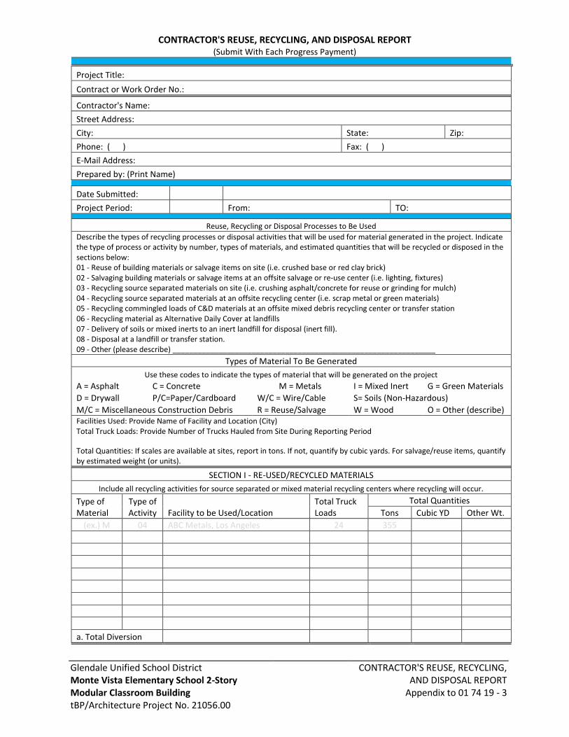
Glendale Unified School District Monte Vista Elementary School 2-Story Modular Classroom Building tBP/Architecture Project No. 21056.00
CONTRACTOR'S REUSE, RECYCLING, AND DISPOSAL REPORT
Appendix to 01 74 19 - 3
CONTRACTOR'S REUSE, RECYCLING, AND DISPOSAL REPORT (Submit With Each Progress Payment)
Project Title:
Contract or Work Order No.:
Contractor's Name:
Street Address:
City: State: Zip:
Phone: ( ) Fax: ( )
E-Mail Address:
Prepared by: (Print Name)
Date Submitted:
Project Period: From: TO:
Reuse, Recycling or Disposal Processes to Be Used
Describe the types of recycling processes or disposal activities that will be used for material generated in the project. Indicate the type of process or activity by number, types of materials, and estimated quantities that will be recycled or disposed in the sections below: 01 - Reuse of building materials or salvage items on site (i.e. crushed base or red clay brick) 02 - Salvaging building materials or salvage items at an offsite salvage or re-use center (i.e. lighting, fixtures) 03 - Recycling source separated materials on site (i.e. crushing asphalt/concrete for reuse or grinding for mulch) 04 - Recycling source separated materials at an offsite recycling center (i.e. scrap metal or green materials) 05 - Recycling commingled loads of C&D materials at an offsite mixed debris recycling center or transfer station 06 - Recycling material as Alternative Daily Cover at landfills 07 - Delivery of soils or mixed inerts to an inert landfill for disposal (inert fill). 08 - Disposal at a landfill or transfer station. 09 - Other (please describe) _______________________________________________________________
Types of Material To Be Generated
Use these codes to indicate the types of material that will be generated on the project
A = Asphalt C = Concrete M = Metals I = Mixed Inert G = Green Materials
D = Drywall P/C=Paper/Cardboard W/C = Wire/Cable S= Soils (Non-Hazardous)
M/C = Miscellaneous Construction Debris R = Reuse/Salvage W = Wood O = Other (describe) Facilities Used: Provide Name of Facility and Location (City) Total Truck Loads: Provide Number of Trucks Hauled from Site During Reporting Period
Total Quantities: If scales are available at sites, report in tons. If not, quantify by cubic yards. For salvage/reuse items, quantify by estimated weight (or units).
SECTION I - RE-USED/RECYCLED MATERIALS
Include all recycling activities for source separated or mixed material recycling centers where recycling will occur.
Type of Material
Type of Activity Facility to be Used/Location
Total Truck Loads
Total Quantities
Tons Cubic YD Other Wt.
(ex.) M 04 ABC Metals, Los Angeles 24 355
a. Total Diversion
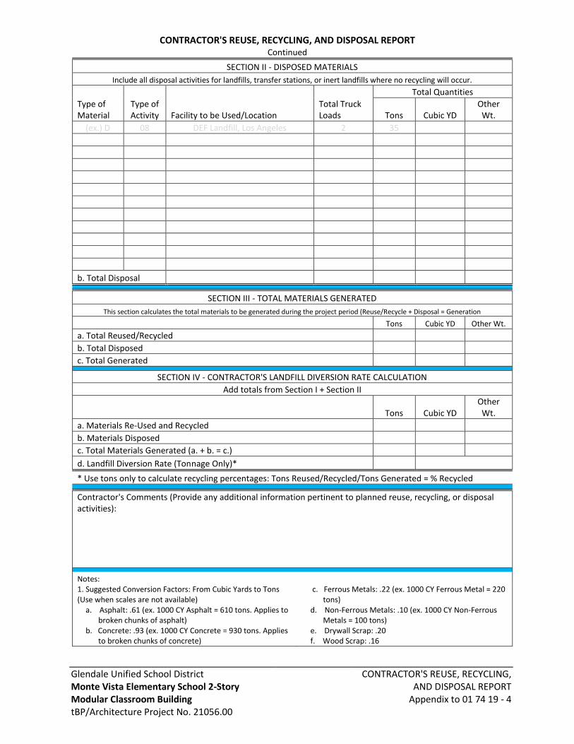
Glendale Unified School District Monte Vista Elementary School 2-Story Modular Classroom Building tBP/Architecture Project No. 21056.00
CONTRACTOR'S REUSE, RECYCLING, AND DISPOSAL REPORT
Appendix to 01 74 19 - 4
CONTRACTOR'S REUSE, RECYCLING, AND DISPOSAL REPORT Continued
SECTION II - DISPOSED MATERIALS
Include all disposal activities for landfills, transfer stations, or inert landfills where no recycling will occur.
Type of Material
Type of Activity Facility to be Used/Location
Total Truck Loads
Total Quantities
Tons Cubic YD
Other Wt.
(ex.) D 08 DEF Landfill, Los Angeles 2 35
b. Total Disposal
SECTION III - TOTAL MATERIALS GENERATED
This section calculates the total materials to be generated during the project period (Reuse/Recycle + Disposal = Generation
Tons Cubic YD Other Wt.
a. Total Reused/Recycled b. Total Disposed c. Total Generated
SECTION IV - CONTRACTOR'S LANDFILL DIVERSION RATE CALCULATION
Add totals from Section I + Section II
Tons Cubic YD
Other Wt.
a. Materials Re-Used and Recycled b. Materials Disposed c. Total Materials Generated (a. + b. = c.)
d. Landfill Diversion Rate (Tonnage Only)*
* Use tons only to calculate recycling percentages: Tons Reused/Recycled/Tons Generated = % Recycled
Contractor's Comments (Provide any additional information pertinent to planned reuse, recycling, or disposal activities):
Notes: 1. Suggested Conversion Factors: From Cubic Yards to Tons (Use when scales are not available)
a. Asphalt: .61 (ex. 1000 CY Asphalt = 610 tons. Applies to broken chunks of asphalt)
b. Concrete: .93 (ex. 1000 CY Concrete = 930 tons. Applies to broken chunks of concrete)
c. Ferrous Metals: .22 (ex. 1000 CY Ferrous Metal = 220 tons)
d. Non-Ferrous Metals: .10 (ex. 1000 CY Non-Ferrous Metals = 100 tons)
e. Drywall Scrap: .20 f. Wood Scrap: .16

Glendale Unified School DistrictMonte Vista Elementary School 2-StoryModular Classroom BuildingtBP/Architecture Project No. 21056.00
CLOSEOUT SUBMITTALS01 78 00 - 1
SECTION 01 78 00CLOSEOUT SUBMITTALS
PART 1 GENERAL
1.01 SECTION INCLUDES
A. Project record documents.
B. Operation and maintenance data.
C. Warranties and bonds.
1.02 RELATED REQUIREMENTS
A. Owner issued Bidding Instructions and General Conditions: Performance bond and labor andmaterial payment bonds, warranty, and correction of work.
B. Section 01 30 00 - Administrative Requirements: Submittals procedures, shop drawings,product data, and samples.
C. Section 01 45 33 - Code-Required Special Inspections: Construction oversight procedures byDSA regarding the execution, approval, and closeout of this building project.
D. Section 01 70 00 - Execution and Closeout Requirements: Contract closeout procedures.
E. Individual Product Sections: Specific requirements for operation and maintenance data.
F. Individual Product Sections: Warranties required for specific products or Work.
1. Special Project warranty requirements for specific products or elements of the Work;commitments and agreements for continuing services to District.
1.03 DEFINITIONS
A. Warranty: Assurance to District by Contractor, installer, supplier, manufacturer or other partyresponsible as warrantor, for the quantity, quality, performance and other representations ofa product, system service of the Work, in whole or in part, for the duration of the specifiedperiod of time.
B. Guarantee: Assurance to District by Contractor or product manufacturer or other specifiedparty, as guarantor, that the specified warranty will be fulfilled by the guarantor in the eventof default by the warrantor.
C. Standard Product Warranty: Preprinted, written warranty published by product manufacturerfor particular products and specifically endorsed by the manufacturer to the District.
D. Special Project Warranty: Written warranty required by or incorporated into ContractDocuments, to extend time limits provided by standard warranty or to provide greater rightsfor District.
E. Correction Period: As defined in the Conditions of the Contract, Correction Period shall besynonymous with "warranty period", "guarantee period" and similar terms used in theContract Specifications.
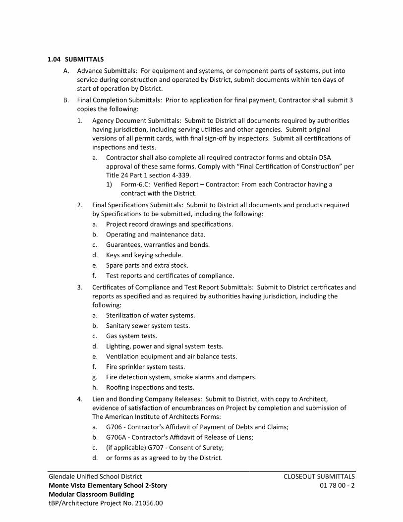
Glendale Unified School DistrictMonte Vista Elementary School 2-StoryModular Classroom BuildingtBP/Architecture Project No. 21056.00
CLOSEOUT SUBMITTALS01 78 00 - 2
1.04 SUBMITTALS
A. Advance Submittals: For equipment and systems, or component parts of systems, put intoservice during construction and operated by District, submit documents within ten days ofstart of operation by District.
B. Final Completion Submittals: Prior to application for final payment, Contractor shall submit 3copies the following:
1. Agency Document Submittals: Submit to District all documents required by authoritieshaving jurisdiction, including serving utilities and other agencies. Submit originalversions of all permit cards, with final sign-off by inspectors. Submit all certifications ofinspections and tests.a. Contractor shall also complete all required contractor forms and obtain DSA
approval of these same forms. Comply with “Final Certification of Construction” perTitle 24 Part 1 section 4-339.1) Form-6.C: Verified Report – Contractor: From each Contractor having a
contract with the District.
2. Final Specifications Submittals: Submit to District all documents and products requiredby Specifications to be submitted, including the following:a. Project record drawings and specifications.b. Operating and maintenance data.c. Guarantees, warranties and bonds.d. Keys and keying schedule.e. Spare parts and extra stock.f. Test reports and certificates of compliance.
3. Certificates of Compliance and Test Report Submittals: Submit to District certificates andreports as specified and as required by authorities having jurisdiction, including thefollowing:a. Sterilization of water systems.b. Sanitary sewer system tests.c. Gas system tests.d. Lighting, power and signal system tests.e. Ventilation equipment and air balance tests.f. Fire sprinkler system tests.g. Fire detection system, smoke alarms and dampers.h. Roofing inspections and tests.
4. Lien and Bonding Company Releases: Submit to District, with copy to Architect,evidence of satisfaction of encumbrances on Project by completion and submission ofThe American Institute of Architects Forms:a. G706 - Contractor's Affidavit of Payment of Debts and Claims;b. G706A - Contractor's Affidavit of Release of Liens;c. (if applicable) G707 - Consent of Surety;d. or forms as as agreed to by the District.

Glendale Unified School DistrictMonte Vista Elementary School 2-StoryModular Classroom BuildingtBP/Architecture Project No. 21056.00
CLOSEOUT SUBMITTALS01 78 00 - 3
e. Comply also with other requirements of District, as directed.f. All signatures shall be notarized.
5. Subcontractor List: Submit to two copies to District and two copies to Architect ofupdated Subcontractor and Materials Supplier List.
6. Warranty Documents: Prepare and submit to District all warranties and bonds asspecified in Contract General Conditions and this Section.
C. Project Record Documents: Submit documents to Architect with claim for final Applicationfor Payment.
D. Operation and Maintenance Data:
1. Submit two copies of preliminary draft or proposed formats and outlines of contentsbefore start of Work. Architect will review draft and return one copy with comments.
2. For equipment, or component parts of equipment put into service during constructionand operated by District, submit completed documents within ten days after acceptance.
3. Submit one copy of completed documents 15 days prior to final inspection. This copywill be reviewed and returned after final inspection, with Architect comments. Revisecontent of all document sets as required prior to final submission.
4. Submit two sets of revised final documents in final form within 10 days after finalinspection.
E. Warranties and Bonds:
1. For equipment or component parts of equipment put into service during constructionwith District's permission, submit documents within 10 days after acceptance.
2. Make other submittals within 10 days after Date of Substantial Completion, prior to finalApplication for Payment.
3. For items of Work for which acceptance is delayed beyond Date of SubstantialCompletion, submit within 10 days after acceptance, listing the date of acceptance asthe beginning of the warranty period.
1.05 WARRANTIES AND GUARANTEES
A. General:
1. Provide all warranties and guarantees with District named as beneficiary.
2. For equipment and products, or components thereof, bearing a manufacturer's warrantyor guarantee that extends for a period of time beyond the Contractor's warranty andguarantee, so state in the warranty or guarantee.
B. Provisions for Special Warranties: Refer to Conditions of the Contract for terms of theContractor's special warranty of workmanship and materials.
C. General Warranty and Guarantee Requirements:
1. Warranty shall be an agreement to repair or replace, without cost and undue hardship toDistrict, Work performed under the Contract which is found to be defective during theCorrection Period (warranty or guarantee) period.

Glendale Unified School DistrictMonte Vista Elementary School 2-StoryModular Classroom BuildingtBP/Architecture Project No. 21056.00
CLOSEOUT SUBMITTALS01 78 00 - 4
2. Repairs and replacements due to improper maintenance or operation, or due to normalwear, usage and weathering are excluded from warranty requirements unless otherwisespecified.
D. Specific Warranty and Guarantee Requirements: Specific requirements are included inproduct Specifications Sections of Divisions 03 through 33, including content and limitations.
E. Disclaimers and Limitations:
1. Manufacturer's disclaimers and limitations on product warranties and guarantees shallnot relieve Contractor of responsibility for warranty and guarantee requirements.
2. This applies to the Work that incorporates such products, nor shall they relieve suppliers,manufacturers, and installers required to countersign special warranties with Contractor.
F. Related Damages and Losses: When correcting warranted Work that has been founddefective, remove and replace other Work that has been damaged as a result of such defector that must be removed and replaced to provide access for correction of warranted Work.
G. Reinstatement of Warranty:
1. When Work covered by a warranty has been found defective and has been corrected byreplacement or rebuilding, reinstate the warranty by written endorsement.
2. The reinstated warranty shall be equal to the original warranty with an equitableadjustment for depreciation.
H. Replacement Cost:
1. Upon determination that Work covered by a warranty has been found to be defective,replace or reconstruct the Work to a condition acceptable to District, complying withapplicable requirements of the Contract Documents.
2. Contractor shall be responsible for all costs for replacing or reconstructing defectiveWork regardless of whether District has benefited from use of the Work through aportion of its anticipated useful service life.
I. District's Recourse:
1. Written warranties made to the District shall be in addition to implied warranties, andshall not limit the duties, obligations, rights and remedies otherwise available under law,nor shall warranty periods be interpreted as limitations on time in which the District canenforce such other duties, obligations, rights, or remedies.
2. Rejection of Warranties:a. The District reserves the right to reject warranties and to limit selections to
products with warranties not in conflict with requirements of the ContractDocuments.
J. Warranty as Condition of Acceptance:
1. District reserves the right to refuse to accept Work for the Project where a specialwarranty, certification, or similar commitment shall be required on such Work or part ofthe Work, until evidence is presented that entities required to countersign suchcommitments are willing to do so.
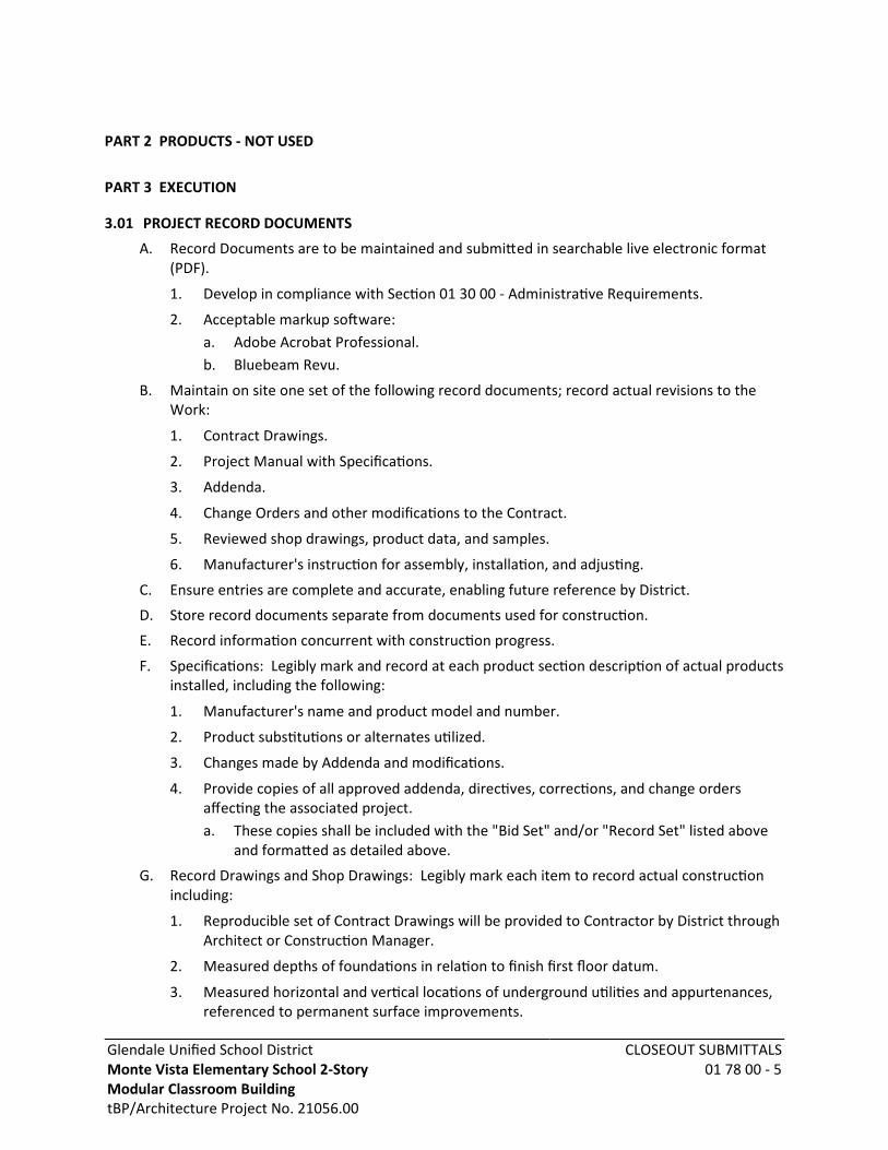
Glendale Unified School DistrictMonte Vista Elementary School 2-StoryModular Classroom BuildingtBP/Architecture Project No. 21056.00
CLOSEOUT SUBMITTALS01 78 00 - 5
PART 2 PRODUCTS - NOT USED
PART 3 EXECUTION
3.01 PROJECT RECORD DOCUMENTS
A. Record Documents are to be maintained and submitted in searchable live electronic format(PDF).
1. Develop in compliance with Section 01 30 00 - Administrative Requirements.
2. Acceptable markup software:a. Adobe Acrobat Professional.b. Bluebeam Revu.
B. Maintain on site one set of the following record documents; record actual revisions to theWork:
1. Contract Drawings.
2. Project Manual with Specifications.
3. Addenda.
4. Change Orders and other modifications to the Contract.
5. Reviewed shop drawings, product data, and samples.
6. Manufacturer's instruction for assembly, installation, and adjusting.
C. Ensure entries are complete and accurate, enabling future reference by District.
D. Store record documents separate from documents used for construction.
E. Record information concurrent with construction progress.
F. Specifications: Legibly mark and record at each product section description of actual productsinstalled, including the following:
1. Manufacturer's name and product model and number.
2. Product substitutions or alternates utilized.
3. Changes made by Addenda and modifications.
4. Provide copies of all approved addenda, directives, corrections, and change ordersaffecting the associated project.a. These copies shall be included with the "Bid Set" and/or "Record Set" listed above
and formatted as detailed above.
G. Record Drawings and Shop Drawings: Legibly mark each item to record actual constructionincluding:
1. Reproducible set of Contract Drawings will be provided to Contractor by District throughArchitect or Construction Manager.
2. Measured depths of foundations in relation to finish first floor datum.
3. Measured horizontal and vertical locations of underground utilities and appurtenances,referenced to permanent surface improvements.

Glendale Unified School DistrictMonte Vista Elementary School 2-StoryModular Classroom BuildingtBP/Architecture Project No. 21056.00
CLOSEOUT SUBMITTALS01 78 00 - 6
4. Measured locations of internal utilities and appurtenances concealed in construction,referenced to visible and accessible features of the Work.
5. Field changes of dimension and detail.
6. Details not on original Contract drawings.a. Application of copies of details produced and provided by Architect during
construction will be accepted.
H. Submission: Submit Record Documents in searchable (live text and redlines mark-ups; notscanned) PDF format to Architect prior to final Application for Payment.
1. Maintain one additional paper copy and one in PDF format (on CD) of the firesuppression and fire protection detection system drawings and specifications at thebuilding premises.a. One copy is to be kept on site for a period of three years to comply with CFC section
901.6.2.
3.02 OPERATION AND MAINTENANCE DATA
A. Source Data: For each product or system, list names, addresses and telephone numbers ofSubcontractors and suppliers, including local source of supplies and replacement parts.
B. Product Data: Mark each sheet to clearly identify specific products and component parts, anddata applicable to installation. Delete inapplicable information.
C. Drawings: Supplement product data to illustrate relations of component parts of equipmentand systems, to show control and flow diagrams. Do not use Project Record Documents asmaintenance drawings.
D. Typed Text: As required to supplement product data. Provide logical sequence ofinstructions for each procedure, incorporating manufacturer's instructions.
3.03 OPERATION AND MAINTENANCE DATA FOR MATERIALS AND FINISHES
A. For Each Product, Applied Material, and Finish:
1. Product data, with catalog number, size, composition, and color and texturedesignations.
2. Information for re-ordering custom manufactured products.
B. Instructions for Care and Maintenance: Manufacturer's recommendations for cleaning agentsand methods, precautions against detrimental cleaning agents and methods, andrecommended schedule for cleaning and maintenance.
C. Moisture protection and weather-exposed products: Include product data listing applicablereference standards, chemical composition, and details of installation. Providerecommendations for inspections, maintenance, and repair.
D. Additional information as specified in individual product specification sections.
E. Where additional instructions are required, beyond the manufacturer's standard printedinstructions, have instructions prepared by personnel experienced in the operation andmaintenance of the specific products.

Glendale Unified School DistrictMonte Vista Elementary School 2-StoryModular Classroom BuildingtBP/Architecture Project No. 21056.00
CLOSEOUT SUBMITTALS01 78 00 - 7
3.04 OPERATION AND MAINTENANCE DATA FOR EQUIPMENT AND SYSTEMS
A. For Each Item of Equipment and Each System:
1. Description of unit or system, and component parts.
2. Identify function, normal operating characteristics, and limiting conditions.
3. Include performance curves, with engineering data and tests.
4. Complete nomenclature and model number of replaceable parts.
B. Where additional instructions are required, beyond the manufacturer's standard printedinstructions, have instructions prepared by personnel experienced in the operation andmaintenance of the specific products.
C. Panelboard Circuit Directories: Provide electrical service characteristics, controls, andcommunications; typed.
D. Include color coded wiring diagrams as installed.
E. Operating Procedures: Include start-up, break-in, and routine normal operating instructionsand sequences. Include regulation, control, stopping, shut-down, and emergencyinstructions. Include summer, winter, and any special operating instructions.
F. Maintenance Requirements: Include routine procedures and guide for preventativemaintenance and trouble shooting; disassembly, repair, and reassembly instructions; andalignment, adjusting, balancing, and checking instructions.
G. Provide servicing and lubrication schedule, and list of lubricants required.
H. Include manufacturer's printed operation and maintenance instructions.
I. Include sequence of operation by controls manufacturer.
J. Provide original manufacturer's parts list, illustrations, assembly drawings, and diagramsrequired for maintenance.
K. Provide control diagrams by controls manufacturer as installed.
L. Provide Contractor's coordination drawings, with color coded piping diagrams as installed.
M. Provide charts of valve tag numbers, with location and function of each valve, keyed to flowand control diagrams.
N. Provide list of original manufacturer's spare parts, current prices, and recommendedquantities to be maintained in storage.
1. Parts Data:a. Provide original manufacturer's parts list, illustrations, assembly drawings, and
diagrams as necessary for service and maintenance.b. Include complete nomenclature and catalog numbers for consumable and
replacement parts.c. Provide list of original manufacturer's spare parts, current prices, and
recommended quantities to be maintained in stock by the District or operator.
O. Include test and balancing reports.
P. Additional Requirements: As specified in individual product specification sections.

Glendale Unified School DistrictMonte Vista Elementary School 2-StoryModular Classroom BuildingtBP/Architecture Project No. 21056.00
CLOSEOUT SUBMITTALS01 78 00 - 8
3.05 ASSEMBLY OF OPERATION AND MAINTENANCE MANUALS
A. Assemble operation and maintenance data into durable manuals for District's personnel use,with data arranged in the same sequence as, and identified by, the specification sections.
1. Provide duplicate electronic formatted (PDF) versions of the O&M binder for recordpurposes. Organize the same as the printed versions.
B. Where systems involve more than one specification section, provide separate tabbed dividerfor each system.
C. Binders: Commercial quality, 8-1/2 by 11 inch three D side ring binders with durable plasticcovers; 2 inch maximum ring size. When multiple binders are used, correlate data intorelated consistent groupings.
D. Cover: Identify each binder with typed or printed title OPERATION AND MAINTENANCEINSTRUCTIONS; identify title of Project; identify subject matter of contents.
E. Project Directory: Title and address of Project; names, addresses, and telephone numbers ofArchitect, Consultants, Contractor and subcontractors, with names of responsible parties.
F. Tables of Contents: List every item separated by a divider, using the same identification as onthe divider tab; where multiple volumes are required, include all volumes Tables of Contentsin each volume, with the current volume clearly identified.
G. Dividers: Provide tabbed dividers for each separate product and system; identify the contentson the divider tab; immediately following the divider tab include a description of product andmajor component parts of equipment.
H. Text: Manufacturer's printed data, or typewritten data on 20 pound paper.
I. Drawings: Provide with reinforced punched binder tab. Bind in with text; fold larger drawingsto size of text pages.
J. Arrangement of Contents: Organize each volume in parts as follows:
1. Project Directory.
2. Table of Contents, of all volumes, and of this volume.
3. Operation and Maintenance Data: Arranged by system, then by product category.a. Source data.b. Product data, shop drawings, and other submittals.c. Operation and maintenance data.d. Field quality control data.e. Photocopies of warranties and bonds.
4. Design Data: To allow for addition of design data furnished by Architect or others,provide a tab labeled "Design Data" and provide a binder large enough to allow forinsertion of at least 20 pages of typed text.
3.06 WARRANTIES AND BONDS
A. Obtain warranties and bonds, executed in duplicate by responsible Subcontractors, suppliers,and manufacturers, within 10 days after completion of the applicable item of work. Exceptfor items put into use with District's permission, leave date of beginning of time of warrantyuntil Date of Substantial completion is determined.
Glendale Unified School DistrictMonte Vista Elementary School 2-StoryModular Classroom BuildingtBP/Architecture Project No. 21056.00
CLOSEOUT SUBMITTALS01 78 00 - 9
B. Project Warranty and Guarantee Forms:
1. Example forms for special Project warranties and guarantees are included at the end ofthis Section.
2. Prepare written documents utilizing the appropriate form, ready for execution by theContractor, or the Contractor and subcontractor, supplier or manufacturer.a. Submit a draft to District through Architect for approval prior to final execution.
3. Refer to product technical Sections for specific content requirements, and particularrequirements for submittal of special warranties.
4. Prepare standard warranties and guarantees, excepting manufacturers' standard printedwarranties and guarantees, on Contractor's, subcontractor's, material supplier's, ormanufacturer's own letterhead, addressed to District.
5. Warranty and guarantee letters shall be signed by all responsible parties and byContractor in every case, with modifications only as approved in advance by District tosuit the conditions pertaining to the warranty or guarantee.
C. Manufacturer's Guarantee Form:
1. Manufacturer's guarantee form may be used in lieu of special Project form included atthe end of this Section.
2. Manufacturer's guarantee form shall contain appropriate terms and identification, readyfor execution by the required parties.
3. If proposed terms and conditions restrict guarantee coverage or require actions byDistrict beyond those specified, submit draft of guarantee to District through Architectfor review and acceptance before performance of the Work.
4. In other cases, submit draft of guarantee to District through Architect for approval priorto final execution of guarantee.
D. Signatures: Signatures shall be by person authorized to sign warranties, guarantees andbonds on behalf of entity providing such warranty, guarantee or bond.
E. Co-Signature: All installer's warranties and bonds shall be co-signed by Contractor. Manufacturer's guarantees will not require co-signature.
F. Verify that documents are in proper form, contain full information, and are notarized.
G. Co-execute submittals when required.
H. Retain warranties and bonds until time specified for submittal.
I. Manual: Bind in commercial quality 8-1/2 by 11 inch three D side ring binders with durableplastic covers.
J. Cover: Identify each binder with typed or printed title WARRANTIES AND BONDS, with title ofProject; name, address and telephone number of Contractor and equipment supplier; andname of responsible company principal.
1. If more than one volume of warranties, guarantees and bonds is produced, identifyvolume number on binder.
K. Table of Contents: Neatly typed, in the sequence of the Table of Contents of the ProjectManual, with each item identified with the number and title of the specification section inwhich specified, and the name of product or work item.

Glendale Unified School DistrictMonte Vista Elementary School 2-StoryModular Classroom BuildingtBP/Architecture Project No. 21056.00
CLOSEOUT SUBMITTALS01 78 00 - 10
L. Separate each warranty or bond with index tab sheets keyed to the Table of Contents listing. Provide full information, using separate typed sheets as necessary. List Subcontractor,supplier, and manufacturer, with name, address, and telephone number of responsibleprincipal.
M. Form of Warranty and Bond Submittals:
1. Prior to final Application and Certificate for Payment, compile two copies of eachrequired warranty, guarantee and bond, properly executed by Contractor, or jointly byContractor, subcontractor, supplier, or manufacturer.
2. Collect and assemble all written warranties and guarantees into binders and deliverbinders to District for final review and acceptance.
3. Include Table of Contents for binder, neatly typed, following order and Section numbersand titles as used in the Project Manual.
4. Provide heavy paper dividers with celluloid or plastic covered tabs for each separatewarranty.a. Mark tabs to identify products or installation, and Section number and title.
5. Include on separate typed sheet, if information is not contained in warranty orguarantee form, a description of the product or installation, and the name, address,telephone number and responsible person for applicable installer, supplier andmanufacturer.
6. When operating and maintenance data manuals are required for warrantedconstruction, include additional copies of each required warranty and guarantee in eachrequired manual.a. Coordinate with requirements listed in the prior articles for operating and
maintenance data manuals.
3.07 TIME OF WARRANTY AND BOND SUBMITTALS
A. Submission of Preliminary Copies:
1. Unless otherwise specified, obtain preliminary copies of warranties, guarantees andbonds within ten days of completion of applicable item or Work.
2. Prepare and submit preliminary copies for review as specified herein.
B. Submission of Final Copies:
1. Submit fully executed copies of warranties, guarantees and bonds within ten days ofdate identified in Certificate of Completion but no later than three days prior to date offinal Application for Payment.
C. Date of Warranties and Bonds:
1. Unless otherwise directed or specified, commencement date of warranty, guarantee andbond periods shall be the date established in the Certificate of Completion.
2. Warranties for Work accepted in advance of date stated in Certificate of Completion:a. When a designated system, equipment, component parts or other portion of the
Work is completed and occupied or put to beneficial use by District:
Glendale Unified School DistrictMonte Vista Elementary School 2-StoryModular Classroom BuildingtBP/Architecture Project No. 21056.00
CLOSEOUT SUBMITTALS01 78 00 - 11
1) By separate agreement with Contractor, prior to completion date establishedin the Certificate of Completion, submit properly executed warranties toDistrict within ten days of completion of that designated portion of the Work.
2) List date of commencement of warranty, guarantee or bond period as the dateestablished in the Certificate of Completion.
3. Warranties for Work not accepted as of date established in the Certificate ofCompletion:a. Submit documents within ten days after acceptance, listing date of acceptance as
beginning of warranty, guarantee or bond period.
D. Duration of Warranties and Guarantees:
1. Unless otherwise specified or prescribed by law, warranty and guarantee periods shall benot less than the Correction Period required by the Conditions of the Contract.
2. In no case, the period is to be less than one year from the date established forcompletion of the Project in the Certificate of Completion.
3. See product Specifications Sections of the Project Manual for extended warranty andguarantee beyond the minimum one year duration.
END OF SECTION
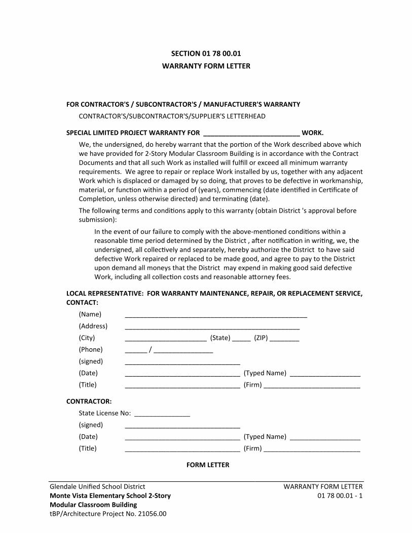
Glendale Unified School DistrictMonte Vista Elementary School 2-StoryModular Classroom BuildingtBP/Architecture Project No. 21056.00
WARRANTY FORM LETTER01 78 00.01 - 1
SECTION 01 78 00.01WARRANTY FORM LETTER
FOR CONTRACTOR'S / SUBCONTRACTOR'S / MANUFACTURER'S WARRANTY
CONTRACTOR'S/SUBCONTRACTOR'S/SUPPLIER'S LETTERHEAD
SPECIAL LIMITED PROJECT WARRANTY FOR __________________________ WORK.
We, the undersigned, do hereby warrant that the portion of the Work described above whichwe have provided for 2-Story Modular Classroom Building is in accordance with the ContractDocuments and that all such Work as installed will fulfill or exceed all minimum warrantyrequirements. We agree to repair or replace Work installed by us, together with any adjacentWork which is displaced or damaged by so doing, that proves to be defective in workmanship,material, or function within a period of (years), commencing (date identified in Certificate ofCompletion, unless otherwise directed) and terminating (date).
The following terms and conditions apply to this warranty (obtain District 's approval beforesubmission):
In the event of our failure to comply with the above-mentioned conditions within areasonable time period determined by the District , after notification in writing, we, theundersigned, all collectively and separately, hereby authorize the District to have saiddefective Work repaired or replaced to be made good, and agree to pay to the Districtupon demand all moneys that the District may expend in making good said defectiveWork, including all collection costs and reasonable attorney fees.
LOCAL REPRESENTATIVE: FOR WARRANTY MAINTENANCE, REPAIR, OR REPLACEMENT SERVICE,CONTACT:
(Name) _________________________________________________
(Address) _______________________________________________
(City) ______________________ (State) _____ (ZIP) ________
(Phone) ______ / ________________
(signed) _______________________________
(Date) _______________________________ (Typed Name) ___________________
(Title) _______________________________ (Firm) __________________________
CONTRACTOR:
State License No: _______________
(signed) _______________________________
(Date) _______________________________ (Typed Name) ___________________
(Title) _______________________________ (Firm) __________________________
FORM LETTER

Glendale Unified School DistrictMonte Vista Elementary School 2-StoryModular Classroom BuildingtBP/Architecture Project No. 21056.00
WARRANTY FORM LETTER01 78 00.01 - 2

Glendale Unified School DistrictMonte Vista Elementary School 2-StoryModular Classroom BuildingtBP/Architecture Project No. 21056.00
WARRANTY FORM LETTER01 78 00.01 - 3
FORM LETTER
FOR CONTRACTOR'S / MANUFACTURER'S GUARANTEE
CONTRACTOR'S / MANUFACTURER'S LETTERHEAD
SPECIAL LIMITED PROJECT [__WARRANTY__] [__GUARANTEE__] FOR ___________ WORK.
We, the undersigned, do hereby [__warrant__] [__guarantee__] that the portion of the Workdescribed above which [__we have provided__] [__was provided by (Installer orSubcontractor's Name)__] for 2-Story Modular Classroom Building in accordance with theContract Documents and that all such Work as installed will fulfill or exceed all minimumwarranty requirements. We agree to repair or replace Work installed by [__us,__][__(Installer or Subcontractor's Name)__] together with any adjacent Work which is displacedor damaged by so doing, that proves to be defective in workmanship, material, or functionwithin a period of (years), commencing (date indicated in Certificate of Completion, unlessotherwise directed) and terminating (date).
The following terms and conditions apply to this [__warranty__] [__guarantee__] (obtainDistrict's approval before submission):
In the event of our failure to comply with the above-mentioned conditions within areasonable time period determined by the District, after notification in writing, we, theundersigned, all collectively and separately, hereby authorize the District to have saiddefective Work repaired or replaced to be made good, and agree to pay to the Districtupon demand all moneys that the District may expend in making good said defectiveWork, including all collection costs and reasonable attorney fees.
LOCAL REPRESENTATIVE: FOR WARRANTY MAINTENANCE, REPAIR, OR REPLACEMENT SERVICE,CONTACT:
(Name) _________________________________________________
(Address) _______________________________________________
(City) ______________________ (State) _____ (ZIP) ________
(Phone) ______ / ________________
(signed) _______________________________
(Date) _______________________________ (Typed Name) ___________________
(Title) _______________________________ (Firm) __________________________
CONTRACTOR:
State License No: _______________
(signed) _______________________________
(Date) _______________________________ (Typed Name) ___________________
(Title) _______________________________ (Firm) __________________________
FORM LETTER

Glendale Unified School DistrictMonte Vista Elementary School 2-StoryModular Classroom BuildingtBP/Architecture Project No. 21056.00
WARRANTY FORM LETTER01 78 00.01 - 4
END OF SECTION

Glendale Unified School DistrictMonte Vista Elementary School 2-StoryModular Classroom BuildingtBP/Architecture Project No. 21056.00
DEMONSTRATION AND TRAINING01 79 00 - 1
SECTION 01 79 00DEMONSTRATION AND TRAINING
PART 1 GENERAL
1.01 SUMMARY
A. Demonstration of products and systems to be commissioned and where indicated in specificspecification sections.
B. Training of District personnel in operation and maintenance is required for:
1. All software-operated systems.
2. HVAC systems and equipment.
3. Plumbing equipment.
4. Electrical systems and equipment.
5. Conveying systems.
6. Landscape irrigation.
7. Items specified in individual product Sections.
C. Training of District personnel in care, cleaning, maintenance, and repair is required for:
1. Roofing, waterproofing, and other weather-exposed or moisture protection products.
2. Finishes, including flooring, wall finishes, ceiling finishes.
3. Fixtures and fittings.
4. Items specified in individual product Sections.
1.02 RELATED REQUIREMENTS
A. Section 01 78 00 - Closeout Submittals: Operation and maintenance manuals.
B. Section 01 91 13 - General Commissioning Requirements: Additional requirements applicableto demonstration and training.
C. Other Specification Sections: Additional requirements for demonstration and training.
1.03 SUBMITTALS
A. See Section 01 30 00 - Administrative Requirements, for submittal procedures.
B. Training Plan: District will designate personnel to be trained; tailor training to needs andskill-level of attendees.
1. Each Sub, Design-Builder SubContractor and vendor responsible for training submits awritten training plan to the Architect and District Representative for review and approvalprior to training.
2. Submit to Architect for transmittal to District.
3. Submit not less than four weeks prior to start of training.
4. Revise and resubmit until acceptable.
5. Provide an overall schedule showing all training sessions.
Glendale Unified School DistrictMonte Vista Elementary School 2-StoryModular Classroom BuildingtBP/Architecture Project No. 21056.00
DEMONSTRATION AND TRAINING01 79 00 - 2
6. Include at least the following for each training session:a. Identification, date, time, and duration.b. Description of products and/or systems to be covered.
1) Equipment listc. Name of firm and person conducting training; include qualifications.d. Intended audience, such as job description.e. Objectives of training and suggested methods of ensuring adequate training.
1) Agenda and subjects (design intent, equipment inspections, modes ofoperation, system interactions, troubleshooting, preventative maintenance,etc.)
f. Methods to be used, such as classroom lecture, live demonstrations, hands-on, etc.g. Media to be used, such a slides, hand-outs, etc.
1) The approved O&M manuals shall be used during the training for equipmentspecific references.
h. Training equipment required, such as projector, projection screen, etc., to beprovided by Contractor.
C. Training Manuals: Provide training manual for each attendee; allow for minimum of twoattendees per training session.
1. Include applicable portion of O&M manuals.
2. Include copies of all hand-outs, slides, overheads, video presentations, etc., that are notincluded in O&M manuals.
3. Provide one extra copy of each training manual to be included with operation andmaintenance data.
D. Training Reports:
1. Identification of each training session, date, time, and duration.
2. Sign-in sheet showing names and job titles of attendees.
3. List of attendee questions and written answers given, including copies of and referencesto supporting documentation required for clarification; include answers to questionsthat could not be answered in original training session.
4. Include Commissioning Authority's formal acceptance of training session.
E. Video Recordings: Submit digital video recording of each demonstration and training sessionfor District's subsequent use.
1. Format: DVD Disc.
2. Label each disc and container with session identification and date.
1.04 QUALITY ASSURANCE
A. Instructor Qualifications: Familiar with design, operation, maintenance and troubleshootingof the relevant products and systems.
1. Provide as instructors the most qualified trainer of those contractors and/or installerswho actually supplied and installed the systems and equipment.
Glendale Unified School DistrictMonte Vista Elementary School 2-StoryModular Classroom BuildingtBP/Architecture Project No. 21056.00
DEMONSTRATION AND TRAINING01 79 00 - 3
2. Where a single person is not familiar with all aspects, provide specialists with necessaryqualifications.
PART 2 PRODUCTS - NOT USED
PART 3 EXECUTION
3.01 TRAINING OF OWNER PERSONNEL
A. The Contractor and Design-Builder SubContractors shall be responsible for trainingcoordination and scheduling and for ensuring that training is completed.
B. The Commissioning Authority (CA) shall be responsible for reviewing and approving thecontent of the training of Owner personnel for commissioned equipment.
C. The specific training requirements of District personnel by Subs, Design-BuilderSubContractors and vendors is specified in the Division in which the equipment is specified.
D. For primary HVAC equipment, the Controls Contractor shall provide a short discussion of thecontrol of the equipment during the mechanical or electrical training conducted by others.
3.02 DEMONSTRATION - GENERAL
A. Demonstrations conducted during system start-up do not qualify as demonstrations for thepurposes of this section, unless approved in advance by District.
B. Demonstrations conducted during Functional Testing need not be repeated unless Districtpersonnel training is specified.
C. Demonstration may be combined with District personnel training if applicable.
D. Operating Equipment and Systems: Demonstrate operation in all modes, including start-up,shut-down, seasonal changeover, emergency conditions, and troubleshooting, andmaintenance procedures, including scheduled and preventive maintenance.
1. Perform demonstrations not less than two weeks prior to Substantial Completion.
2. For equipment or systems requiring seasonal operation, perform demonstration forother season within six months.
E. Non-Operating Products: Demonstrate cleaning, scheduled and preventive maintenance, andrepair procedures.
1. Perform demonstrations not less than two weeks prior to Substantial Completion.
3.03 TRAINING - GENERAL
A. Commissioning Authority will prepare the Training Plan based on draft plans submitted.
B. Conduct training on-site unless otherwise indicated.
C. District will provide classroom and seating at no cost to Contractor.
D. Do not start training until Functional Testing is complete, unless otherwise specified orapproved by the Commissioning Authority.
E. Provide training in minimum two hour segments.

Glendale Unified School DistrictMonte Vista Elementary School 2-StoryModular Classroom BuildingtBP/Architecture Project No. 21056.00
DEMONSTRATION AND TRAINING01 79 00 - 4
F. The Commissioning Authority is responsible for determining that the training wassatisfactorily completed and will provide approval forms.
G. Training schedule will be subject to availability of District's personnel to be trained;re-schedule training sessions as required by District; once schedule has been approved byDistrict failure to conduct sessions according to schedule will be cause for District to chargeContractor for personnel "show-up" time.
H. Review of Facility Policy on Operation and Maintenance Data: During training discuss:
1. The location of the O&M manuals and procedures for use and preservation; backupcopies.
2. Typical contents and organization of all manuals, including explanatory information,system narratives, and product specific information.
3. Typical uses of the O&M manuals.
I. Product- and System-Specific Training:
1. Review the applicable O&M manuals.
2. For systems, provide an overview of system operation, design parameters andconstraints, and operational strategies.
3. Review instructions for proper operation in all modes, including start-up, shut-down,seasonal changeover and emergency procedures, and for maintenance, includingpreventative maintenance.
4. Provide hands-on training on all operational modes possible and preventivemaintenance.
5. Emphasize safe and proper operating requirements; discuss relevant health and safetyissues and emergency procedures.
6. Discuss common troubleshooting problems and solutions.
7. Discuss any peculiarities of equipment installation or operation.
8. Discuss warranties and guarantees, including procedures necessary to avoid voidingcoverage.
9. Review recommended tools and spare parts inventory suggestions of manufacturers.
10. Review spare parts and tools required to be furnished by Contractor.
11. Review spare parts suppliers and sources and procurement procedures.
J. Be prepared to answer questions raised by training attendees; if unable to answer duringtraining session, provide written response within three days.
END OF SECTION
Glendale Unified School District Monte Vista Elementary School 2-Story Modular Classroom Building tBP/Architecture Project No. 21056.00
DEMOLITION 02 41 00 - 1
SECTION 02 41 00
DEMOLITION
PART 1 - GENERAL
1.01 SUMMARY
A. Section Includes: Furnishing all labor, materials and equipment necessary for demolition, dismantling, cutting and alterations as indicated, specified, and required for completion of the Contract, as applicable. Includes items such as the following:
1. Protecting existing work to remain.
2. Cleaning soiled materials that are to remain.
3. Disconnecting and capping utilities.
4. Removing debris and equipment.
5. Removal of items indicated on Drawings.
6. Salvageable items to be retained by the Owner as indicated on the Drawings and during the pre-construction job walk.
B. Related Sections:
1. Section 31 22 00: Grading
1.02 QUALITY ASSURANCE
A. Comply with the following:
1. Applicable codes, ordinances, regulations of local, municipal, state and federal authorities having jurisdiction.
2. Comply strictly to Rule 403 Fugitive Dust, South Coast Air Quality Management District.
3. Obtain necessary permits and notices, post where required.
4. Comply with safety requirements of the local fire department.
5. Comply with ANSI A10.6.
B. Notify affected utility companies before starting Work and comply with their requirements.
C. Carefully perform demolition work, by skilled workers experienced in building demolition procedures, using appropriate tools and equipment. Perform work, at all times, under the direct supervision of a supervisor approved by the Owner Inspector.

Glendale Unified School District Monte Vista Elementary School 2-Story Modular Classroom Building tBP/Architecture Project No. 21056.00
DEMOLITION 02 41 00 - 2
D. Coordinate demolition with other trades to ensure correct sequence, limits, and methods of proposed demolition. Schedule work to create least possible inconvenience to the public and to facility operations.
E. Pre-Demolition: Conduct conference at Project site 7 days prior to scheduled installation.
1. Conference agenda shall include review and discussion of requirements of authorities having jurisdiction, instructions and requirements of serving utilities, sequencing and interface considerations and Project conditions.
2. Conference shall be attended by supervisory and quality control personnel of Contractor and all subcontractors performing this and directly related work. Submit minutes of meeting to Design Builder’s Representative for Project record purposes.
1.03 DEFINITIONS
A. Remove: Remove and legally dispose of items except those indicated to be reinstalled, salvaged, or to remain the Owner's property.
B. Remove and Salvage: Items indicated to be removed and salvaged remain the Owner's property. Remove, clean, and pack or crate items to protect against damage. Identify contents of containers and deliver to location as directed by Owner's Representative.
C. Remove and Reinstall: Remove items indicated; clean, service, and otherwise prepare them for reuse; store and protect against damage. Reinstall items in locations indicated.
D. Existing to Remain: Protect construction indicated to remain against damage and soiling during demolition. When permitted by the Owner's Representative, items may be removed to a suitable, protected storage location during demolition and then cleaned and reinstalled in their original locations.
E. Replace: Remove and legally dispose of existing item(s) indicated and install new like item(s) that conform to project specifications.
1.04 OWNERSHIP OF MATERIALS
A. Ownership of Materials: Except for items or materials indicated to be reused, salvaged, or otherwise indicated to remain the Owner's property, demolished materials shall become the Contractor's property and shall be removed from the site with further disposition at the Contractor's option.
1.05 PROJECT CONDITIONS
A. Drawings may not indicate in detail all demolition work to be carried out. Carefully examine existing conditions to determine full extent of demolition required. All utilities, whether shown on the drawings or not, to be capped at the property line U.N.O.
B. Repair damage due to demolition activities to existing improvements to remain at no additional cost to the Owner. Repair or replace as directed by the Owner Inspector.
Glendale Unified School District Monte Vista Elementary School 2-Story Modular Classroom Building tBP/Architecture Project No. 21056.00
DEMOLITION 02 41 00 - 3
C. Take measures to avoid excessive damage from inadequate or improper means and methods, or improper shoring, bracing or support. Repair or replace any resulting damage at no additional cost to the owner as directed by the Owner Inspector.
D. If conditions are encountered that vary from those indicated, notify the Owner Inspector for instructions prior to proceeding. Owner assumes no responsibility for actual condition of structures to be demolished.
E. Inform Owner immediately upon discovery of asbestos products, radioactive materials, toxic wastes or other hazardous materials. Do not remove hazardous materials without Owner authorization.
F. Adjacent roadways/passageways:
1. Maintain fire department access through all phases of the project.
2. Obstruction of streets, walks or other adjacent facilities will not be allowed.
1.06 DIG ALERT NOTIFICATION
A. Before any excavation in or near the public right-of-way, the Contractor must contact the Underground Service Alert of Southern California (Dig Alert) at 811 for information on buried utilities and pipelines.
B. Delineation of the proposed excavation site is mandatory. Mark the area to be excavated with water soluble or chalk based white paint on paved surfaces or with other suitable markings such as flags or stakes on unpaved areas.
C. Call at least Two (2) full working days prior to digging.
D. If the members (utility companies) have facilities within the work area, they will mark them prior to the start of your excavation and if not, they will let you know there is no conflict. A different color is used for each utility type (electricity is marked in red, gas in yellow, water in blue, sewer in green, telephone and cable TV in orange).
E. The Law requires you to hand expose to the point of no conflict 24" (inches) on either side of the underground facility, so you know its exact location before using power equipment.
F. If caught digging without a Dig Alert ticket you can be fined as much as $50,000 per California government code 4216.
PART 2 - PRODUCTS
2.01 SOIL MATERIALS
A. Satisfactory Soil Materials: Refer to section 31 22 00 Grading.
B. Backfill & Native Fill Materials: Refer to section 31 22 00 Grading.

Glendale Unified School District Monte Vista Elementary School 2-Story Modular Classroom Building tBP/Architecture Project No. 21056.00
DEMOLITION 02 41 00 - 4
C. Borrow / Imported Fill Material: Refer to section 31 22 00 Grading.
D. Engineered Fill: All engineered fill should be placed on competent, scarified and compacted bottom as evaluated by the geotechnical engineer. Prior to compaction, fill materials should be thoroughly mixed and moisture conditioned to within three (3) percent of the optimum moisture content for granular soils and to approximate three (3) percent above the optimum moisture for fine-grained soils. Fill soils shall be evenly spread in maximum 8-inch lifts, watered or dried as necessary, mixed and compacted to at least the density specified below. The fill shall be placed and compacted on a horizontal plane, unless otherwise approved by the geotechnical engineer. All fill, if not specified otherwise elsewhere in this report, should be compacted to at least 90 percent of the laboratory dry density in accordance with the ASTM Standard D2922 test method.
2.02 HANDLING OF MATERIALS
A. Items scheduled for salvage by the Owner shall be delivered to a location designated by the Owner’s Authorized Representative. Items shall be cleaned, packaged and labeled for storage.
B. Items scheduled for reuse shall be stored on site and protected from damage, soiling and theft.
PART 3 - EXECUTION
3.01 GENERAL
A. Protection:
1. Do not begin demolition until safety partitions, barricades, warning signs and other forms of protection are installed.
2. Provide safeguards, including warning signs, lights and barricades, for protection of occupants and the general public during demolition.
3. Provide and maintain fire extinguishers. Comply with requirements of governing authorities.
4. Maintain existing utilities which are to remain in service and protect from damage during operations.
B. Safety: If at any time safety of existing construction appears to be endangered, take immediate measures to correct such conditions; cease operations and immediately notify the Owner Inspector. Do not resume demolition until directed by the Owner Inspector.
C. Noise and Dust Abatement: Exercise all reasonable and necessary means to abate dust, dirt rising and undue noise. Perform necessary sprinkling and wetting of construction site to allay dust as required by applicable codes and ordinances
D. Dust Control: Use water mist, temporary enclosures, and other suitable methods to limit the spread of dust and dirt. Comply with governing environmental protection regulations. Do not create hazardous or objectionable conditions, such as flooding and pollution, when using water.
Glendale Unified School District Monte Vista Elementary School 2-Story Modular Classroom Building tBP/Architecture Project No. 21056.00
DEMOLITION 02 41 00 - 5
E. Water for Dust Control: Contractor shall obtain and pay for all water required for his dust control operations. This may include, but is not limited to, payment of deposits to utility for construction meter, and payment of all monthly service and water charges. Construction meter shall be in place throughout construction period unless alternative arrangements are made with the local water purveyor to provide construction water for all purposes. Contractor shall be aware of water moratoriums and restrictions, and shall immediately advise Owner of effects on construction schedules.
F. An 8 foot high, chain link fence and gates, shall be erected prior to any demolition operations at the construction limits perimeter. Coordinate the exact location with Owner.
G. Debris Removal: Remove and transport debris in a manner that will prevent spillage on adjacent surfaces and areas. Remove debris from elevated portions of building by chute, hoist, or other device that will convey debris to grade level.
H. Progress Cleaning: Clean adjacent buildings and improvements of dust, dirt, and debris caused by demolition operations. Return adjacent areas to condition existing before start of demolition.
I. Where performing contracted scope of work requires coring of existing concrete, brick masonry, or CMU structures (including Walls, Floors, and Sitework), contractor shall obtain and document means of verifying existence and location of embedded steel reinforcing materials within said concrete, brick and CMU assemblies. Contractor shall locate reinforcement by means of non-invasive technology such as X-ray photography for the purposes of protecting said reinforcement in place and shall not damage any reinforcement materials (rebar, etc.) unless specifically detailed as such and approved by the authority having jurisidiction.
J. Perform surveys as the Work progresses to detect hazards resulting from selective demolition activities.
K. Drain, purge, or otherwise remove, collect, and dispose of chemicals, gases, explosives, acids, flammables, or other dangerous materials before proceeding with selective demolition operations.
L. Contractor shall provide temporary weather protection, during interval between demolition and removal of existing construction, on exterior surfaces and new construction to ensure that no water leakage or damage occurs to structure or interior areas.
M. Provide and maintain interior and exterior shoring, bracing, or structural support to preserve stability and prevent movement, settlement, or collapse of building to be selectively demolished.
N. Clean adjacent structures and improvements of dust, dirt, and debris caused by selective demolition operations. Return adjacent areas to condition existing before start of selective demolition.
O. Where repairs to existing surfaces are required, patch to produce surfaces suitable for new materials if exposed, repaired surfaces shall match existing adjacent surface color finish and texture.
Glendale Unified School District Monte Vista Elementary School 2-Story Modular Classroom Building tBP/Architecture Project No. 21056.00
DEMOLITION 02 41 00 - 6
1. Restore exposed finishes of patched areas and extend finish restoration into adjoining construction to remain in a manner that eliminates evidence of patching and refinishing.
P. Disposal: Promptly dispose of demolished materials. Do not allow demolished materials to accumulate on-site.
3.02 PREPARATION
A. Prevent movement or settlement of adjacent structures. Provide bracing and shoring as necessary.
B. Utilities:
1. The Drawings do not purport to show all below-grade conditions and objects on the site. Contractor shall perform field investigations as necessary to establish location of underground utility services and other features affecting earthwork.
2. Mark location of underground utilities on asphalt pavement with paint
3. Disconnect and cap utility services; comply with requirement of governing authorities.
4. Contractor shall arrange and notify utility company in advance of date and time when service needs to be disconnected.
5. Do not commence demolition operations until associated disconnections have been completed.
6. Should utilities and other below-grade conditions be encountered which adversely affect the Work, discontinue affected Work and notify Owner's Representative and Architect and request direction. Unforeseen conditions will be resolved in accordance with provisions of the General Conditions of the Contract.
7. Should a utility line or structure be damaged, immediately notify the responsible utility company or agency and notify Owner’s Representative and Architect.
a. Repair or replace all damaged utility lines and structures as directed by the responsible utility company or agency.
b. Repair or replacement of damaged utility lines and structures whole location or existence has been made known to the Contractor shall be at no change in the Contract Time and Contract Price.
C. Structures to be demolished shall be inspected for hazardous materials. Such materials shall be removed and disposed of before general demolition begins.
D. Do not interrupt existing utilities serving occupied or operating facilities, except when authorized in writing by Owner's Representative and Authority Having Jurisdiction (AHJ). Provide

Glendale Unified School District Monte Vista Elementary School 2-Story Modular Classroom Building tBP/Architecture Project No. 21056.00
DEMOLITION 02 41 00 - 7
temporary services during interruptions to existing utilities, as acceptable to Owner's Representative and to Authority Having Jurisdiction (AHJ).
3.03 EXPLOSIVES
A. Explosives: Use of explosives will not be permitted.
3.04 DEMOLITION
A. Demolition, General:
1. With certain exceptions, the Contractor shall raze, remove and dispose of all buildings and foundations, structures, paving, fences and other obstructions that lie wholly or partially within the construction limits identified on Drawings. The exceptions are utility-owned equipment and any other items the Owner/Documents may direct the Contractor to leave intact or re-use onsite. Cease demolition immediately if adjacent structures appear to be in danger.
2. Conduct demolition operations and remove debris to ensure minimum interference with roads, streets, walks, and other adjacent occupied and used facilities.
3. Do not close or obstruct streets, walks, or other adjacent occupied or used facilities without permission from Owner's Representative and Authority Having Jurisdiction (AHJ). Provide alternate routes around closed or obstructed traffic ways if required by governing regulations.
4. Conduct demolition operations to prevent injury to people and damage to adjacent buildings and facilities to remain. Ensure safe passage of people around demolition area.
a. Erect temporary protection, such as walks, fences, railings, canopies, and covered passageways, where required by authorities having jurisdiction.
b. Protect existing site improvements, appurtenances, and landscaping to remain.
c. Completely remove below-grade construction, including foundation walls and footings.
5. Filling Below-Grade Areas: Completely fill below-grade areas and voids resulting from demolition of buildings and pavements with soil materials according to requirements specified in Section 31 22 00 Grading.
6. Damages: Promptly repair damages to adjacent facilities caused by demolition operations.
7. Unless otherwise indicated on the plans, remove all demolished material from the site and dispose of at approved disposal sites. Comply with all requirements for recycling of demolished material as called for in Division 1 of this Specification. The contractor shall obtain necessary permits for the transportation of material from the site.

Glendale Unified School District Monte Vista Elementary School 2-Story Modular Classroom Building tBP/Architecture Project No. 21056.00
DEMOLITION 02 41 00 - 8
3.05 REMOVAL OF EXISTING PLUMBING AND ELECTRICAL EQUIPMENT AND SERVICES
A. Remove existing plumbing and electrical equipment fixtures and services not indicated for reuse and not necessary for completion of work. Remove abandoned lines and cap unused portions of existing lines. The Contractor is responsible for completely surveying the site and locating all existing utilities, above and below ground, before contracting to perform the work.
B. Asbestos – Cement (A-C) Pipe Removal and Disposal: The plans for the project may indicate that existing asbestos-cement pipe is to be removed from the ground. Where so indicated the Contractor shall excavate with care, expose the pipeline and remove the A-C pipe to the nearest joint. Should the plans not call out the removal of the A-C pipe and A-C pipe is encountered, the Contractor shall obtain approval from the Owner as to whether or not the A-C pipe is to be removed or can be left in place. Cutting of the pipe shall only be done if absolutely there is no other way to expose the length of pipe to the nearest joint that be separated and the Owner approves the cutting of the pipe. Cutting of the pipe shall be done with a mechanical saw with a pressure water source to dampen the pipe and the dust from the cutting. To remove a coupling, the coupling may have to be broken in the trench. The pipe once removed from the trench may be broken for handling. The breaking shall be done within a plastic bagging or sheeting material to minimize the release of asbestos fibers into the atmosphere. Once removed and broken, if necessary, the A-C material shall be bagged and disposed of legally with the Owner to be given a copy of all Contractor paperwork as to the legal disposal of the material. If the A-C pipe section(s) are removed intact the pipe can be removed by the Contractor from the project site and become the property and responsibility of the Contractor.
3.06 CLEANING
A. Clean existing materials to remain, using appropriate tools and materials.
B. Protect adjacent materials and equipment during cleaning operations.
3.07 RESTORATION
A. Restoration of Site Finishes:
1. Concrete paving: Where it is necessary to excavate a trench across make a cut in concrete paved areas, cut concrete cutting saw, full depth of paving.
2. Bituminous paving: Where it is necessary to excavate a trench across make a cut in bituminous paved areas, either first score paving with a concrete cutting saw, in neat straight lines, prior to removing paving or make straight cuts with pneumatic spade.
3. Restoration of paving: Restore all paved areas to their original condition using material of like type and quality as the removed paving. Paving in public ways shall conform to applicable requirements of authorities having jurisdiction. Repaired surfaces shall match existing adjacent paving except minimum depth shall be 3-1/2 inches where existing paving is less than 3-1/2 inches.

Glendale Unified School District Monte Vista Elementary School 2-Story Modular Classroom Building tBP/Architecture Project No. 21056.00
DEMOLITION 02 41 00 - 9
4. Restoration of landscape planting: Restore soil and plant materials to match original condition, including additional topsoil, topsoil grading and preparation, new plant materials and plant maintenance during establishment period.
3.08 MAINTENANCE
A. Install and maintain all erosion control devices, including sandbag and gravel bag dikes, silt fences, de-silting basins, inlet barricades, vehicle wash traps, and other features called for in specification 01 57 23 Temporary Storm Water Pollution Control.
3.09 CLEAN-UP/DISPOSAL
A. Coordinate building access with the Owner Inspector. Review and schedule waste storage and removal, include truck access to site.
B. Debris shall be dampened by fog water spray prior to transporting by truck.
C. Debris pick-up area shall be kept broom-clean and shall be washed daily with clean water.
D. Remove waste and debris, other than items to be salvaged. Turn over salvaged items to Owner, or store and protect for reuse where scheduled. Continuously clean-up and remove items as demolition work progresses. Do not allow waste and debris to accumulate in building or on site.
END OF SECTION
Glendale Unified School DistrictMonte Vista Elementary School 2-StoryModular Classroom BuildingtBP/Architecture Project No. 21056.00
CONCRETE FORMING ANDACCESSORIES
03 10 00 - 1
SECTION 03 10 00CONCRETE FORMING AND ACCESSORIES
PART 1 GENERAL
1.01 SECTION INCLUDES
A. Formwork for cast-in place concrete, with shoring, bracing and anchorage.
B. Openings for other work.
C. Form accessories.
D. Form stripping.
1.02 RELATED REQUIREMENTS
A. Section 03 20 00 - Concrete Reinforcing.
B. Section 03 30 00 - Cast-in-Place Concrete.
C. Section 04 20 00 - Unit Masonry: Reinforcement for masonry.
D. Section 05 50 00 - Metal Fabrications: Placement of embedded steel anchors and plates incast-in-place concrete.
E. Section 32 13 13 - Concrete Paving: Sidewalks, curbs and gutters.
1.03 REFERENCE STANDARDS
A. ACI 117 - Specifications for Tolerances for Concrete Construction and Materials.
B. ACI 301 - Specifications for Structural Concrete.
C. ACI 318 - Building Code Requirements for Structural Concrete and Commentary.
D. ACI 347R - Guide to Formwork for Concrete.
E. PS 1 - Structural Plywood.
F. CBC Chapter 19A.
1.04 DEFINITIONS
A. Unexposed Finish: A general-use finish, with no appearance criteria, applicable to all formedconcrete concealed from view after completion of construction.
B. Exposed Finish: A general-use finish applicable to all formed concrete exposed to view andincluding surfaces which may receive a paint coating (if any).
1.05 SUBMITTALS
A. See Section 01 30 00 - Administrative Requirements, for submittal procedures.
B. Product Data: Provide data on void form materials and installation requirements.
1. Form release agent.
C. Shop Drawings: Indicate pertinent dimensions, materials, bracing, and arrangement of jointsand ties.

Glendale Unified School DistrictMonte Vista Elementary School 2-StoryModular Classroom BuildingtBP/Architecture Project No. 21056.00
CONCRETE FORMING ANDACCESSORIES
03 10 00 - 2
1.06 QUALITY ASSURANCE
A. Industry Standard: Formwork design and construction shall be in accordance with ACI 301,ACI 318, and ACI 347R.
B. Maintain one copy of each installation standard on site throughout the duration of concretework.
C. Regulatory Requirements: Conform to formwork construction requirements of the CaliforniaBuilding Code (CBC) Title 24, Part 2, Chapter 19A as amended and adopted by authoritieshaving jurisdiction.
1.07 DELIVERY, STORAGE, AND HANDLING
A. Deliver prefabricated forms and installation instructions in manufacturer's packaging.
B. Store prefabricated forms off ground in ventilated and protected manner to preventdeterioration from moisture.
PART 2 PRODUCTS
2.01 FORMWORK - GENERAL
A. Provide concrete forms, accessories, shoring, and bracing as required to accomplishcast-in-place concrete work.
B. Design and construct concrete that complies with design with respect to shape, lines, anddimensions.
C. Chamfer outside corners of beams, joists, columns, and walls.
D. Comply with applicable state and local codes with respect to design, fabrication, erection, andremoval of formwork.
E. Comply with relevant portions of ACI 347R, ACI 301, and ACI 318.
F. Provide materials for contact with concrete which impart suitable surface quality tocompleted concrete. Use the following form types:
1. Forms for Exposed Finish Concrete:a. Plywood, metal, metal-framed plywood faced, or other acceptable panel-type
materials to provide continuous, straight, smooth, exposed surfaces.b. Furnish in largest practical sizes to minimize number of joints and to conform to
joint system shown on the Drawings.
2. Forms for Unexposed Finish Concrete:a. Plywood, lumber, metal, or another acceptable material.b. Provide lumber dressed on at least two edges and one side for tight fit.c. When unexposed concrete is intended to receive waterproofing, provide form as for
exposed finish concrete.
G. Provide materials to construct formwork to support forming materials in contact withconcrete, of sufficient capacity to withstand pressures of concrete placement and to supportconcrete in place until cured, without distortion.
Glendale Unified School DistrictMonte Vista Elementary School 2-StoryModular Classroom BuildingtBP/Architecture Project No. 21056.00
CONCRETE FORMING ANDACCESSORIES
03 10 00 - 3
2.02 WOOD FORM MATERIALS
A. Softwood Plywood for Concealed Surfaces: PS 1,undamaged face C Grade, Group 2 PluggedEXT or APA Structural I Sheathing.
B. Hardboard: For curved surfaces, tempered hardboard, Masonite Corp., or equal.
C. Lumber: Douglas fir or douglas fir-larch species; appropriate for intended use grade; withgrade stamp clearly visible.
1. Sound and undamaged straight edges, and solid knots, to maintain principal shores tosupport concrete until minimum strength is achieved as approved by StructuralEngineer.
D. Embedded Nailers: Clear all heart redwood or pressure preservative-treated (PPTDF) douglasfir, edges reverse beveled to key into concrete.
2.03 FORMWORK ACCESSORIES
A. Form Ties: Removable, adjustable-length or snap-off type, galvanized metal, fixed length,cone type, with waterproofing washer, free of defects that could leave holes larger than 1inch in concrete surface.
B. Form Release Agent: Capable of releasing forms from hardened concrete without staining ordiscoloring concrete or forming bugholes and other surface defects, compatible with concreteand form materials, and not requiring removal for satisfactory bonding of coatings to beapplied.
1. Do not use materials containing diesel oil or petroleum-based compounds.
2. Does not impair subsequent treatments of concrete surfaces or bond of appliedcoatings.
3. VOC Content: In compliance with applicable local, State, and federal regulations.
4. Products:a. SpecChem, LLC; Bio Strip WB (water-based): www.specchemllc.com/#sle.b. W. R. Meadows, Inc; Duogard: www.wrmeadows.com/#sle.c. Substitutions: See Section 01 60 00 - Product Requirements.
C. Nails, Spikes, Lag Bolts, Through Bolts, Anchorages: Sized as required, of sufficient strengthand character to maintain formwork in place while placing concrete.
D. Embedded Anchor Shapes, Plates, Angles and Bars: As specified in Section 05 50 00.
E. Screed Pins and Chairs:
1. Provide units that leave no metal closer than 1-1/2 inch to the plane of the exposedconcrete surface.
2. Manufacturers:a. Grann Adjustable Quick Screed (800/554-7266).b. Dayton Richmond (800/745-3700).c. Aztek (877/531-3344).d. Substitutions: See Section 01 60 00 - Product Requirements.
Glendale Unified School DistrictMonte Vista Elementary School 2-StoryModular Classroom BuildingtBP/Architecture Project No. 21056.00
CONCRETE FORMING ANDACCESSORIES
03 10 00 - 4
PART 3 EXECUTION
3.01 EXAMINATION
A. Verify lines, levels and centers before proceeding with formwork. Ensure that dimensionsagree with drawings.
3.02 SYSTEM REQUIREMENTS
A. Formwork Design Requirements: Formwork products and execution specified herein are forfinish surface quality only.
1. Design, layout and construction of formwork shall be solely the responsibility of theContractor.
2. Design and construct formwork, shoring and bracing to conform to California BuildingCode (CBC), Title 24, Part 2, Chapter 19A requirements and ACI 318.
3. Resulting concrete shall conform to shapes, lines and dimensions indicated and required.
B. Coordination:
1. Coordinate Work specified in this Section with other Sections which require placementof embedded products and provision of openings and recesses.
2. If formwork is placed after reinforcement, resulting in insufficient concrete cover overreinforcement, request instructions from the Architect before proceeding.
3.03 EARTH FORMS
A. Earth (Soil) Forms, General: Except as otherwise indicated on Drawings, conform to ACI 301,ACI 347R and California Building Code (CBC) requirements. Refer also to notes on StructuralDrawings.
B. Hand trim sides and bottom of earth forms. Remove loose soil prior to placing concrete.
3.04 ERECTION - FORMWORK
A. Erect formwork, shoring and bracing to achieve design requirements, in accordance withrequirements of ACI 301, ACI 347R and California Building Code (CBC) Title 24, Part 2requirements.
B. Provide bracing to ensure stability of formwork. Shore or strengthen formwork subject tooverstressing by construction loads.
1. Use form ties of sufficient strength and sufficient quantities to prevent formworkspreading.
2. Maintain principal shores to support concrete until minimum required strength isachieved.
C. Arrange and assemble formwork to permit dismantling and stripping. Do not damageconcrete during stripping. Permit removal of remaining principal shores.
1. Design and fabricate forms for easy removal, without impact, shock, or damage toconcrete surfaces or other portions of the work.
Glendale Unified School DistrictMonte Vista Elementary School 2-StoryModular Classroom BuildingtBP/Architecture Project No. 21056.00
CONCRETE FORMING ANDACCESSORIES
03 10 00 - 5
2. Design to support all applied loads until concrete is adequately cured, within allowabletolerances and deflection limits.
D. Align joints and make watertight. Keep form joints to a minimum. Make forms watertight toprevent leakage of concrete mortar. Locate form joints, at exposed concrete, to besymmetrical about center of panel, unless otherwise noted. Align joints symmetrically atexposed conditions.
E. Permanent openings: Provide openings to accommodate Work specified in other Sections. Size and locate openings accurately. Securely support items built into forms; provideadditional bracing at openings and discontinuities in formwork.
F. Temporary openings: Provide temporary openings for cleaning and inspection. Provide drainopenings at bottoms of formwork to allow water to drain. Locate temporary openings inmost inconspicuous locations at base of forms, closed with tight-fitting panels designed tominimize appearance of joints in finished concrete Work.
G. Obtain approval before framing openings in structural members that are not indicated ondrawings.
H. Coordinate this section with other sections of work that require attachment of componentsto formwork.
I. If formwork is placed after reinforcement, resulting in insufficient concrete cover overreinforcement, request instructions from Architect before proceeding.
J. Inspection: Before placing of concrete, and after placement of reinforcing steel in the forms,provide notification so that proper inspection can be made. Make such notification at least 2working days in advance of placing concrete.
K. Rejection of Defective Work: Any movement or bellying of forms during construction orvariations in excess of the tolerances specified shall be considered just cause for the removalof such forms and, in addition, the concrete construction so affected. Reconstruct forms,place new concrete and required reinforcing steel at no additional cost to the District.
3.05 APPLICATION - FORM RELEASE AGENT
A. Form Release Agent: Provide either form materials with factory applied non-absorptive lineror field applied form coating to comply with applicable air quality regulations for VOC. If fieldapplied coating is employed, thoroughly clean and recondition formwork and reapply coatingbefore each use. Rust on form surfaces is not acceptable.
B. Apply form release agent on formwork in accordance with manufacturer's recommendations.
C. Apply prior to placement of reinforcing steel, anchoring devices, and embedded items.
D. Do not apply form release agent where concrete surfaces to receive special finishes or appliedcoverings that are affected by agent. Soak inside surfaces of untreated forms with cleanwater. Keep surfaces coated prior to placement of concrete.
3.06 INSERTS, EMBEDDED PARTS, AND OPENINGS
A. Provide formed openings where required for items to be embedded in passing throughconcrete work.
1. Install accessories in accordance with manufacturer's instructions and referencedstandards, level, straight and plumb.

Glendale Unified School DistrictMonte Vista Elementary School 2-StoryModular Classroom BuildingtBP/Architecture Project No. 21056.00
CONCRETE FORMING ANDACCESSORIES
03 10 00 - 6
B. Locate and set in place items that are cast directly into concrete.
C. Coordinate with work of other sections in forming and placing openings, slots, reglets,recesses, sleeves, bolts, anchors, other inserts, and components of other work.
1. Openings: Size and locate formed openings, depressions, recesses and chases toaccommodate products to be applied to, built into and pass through concrete Work. Coordinate size, location and placement of inserts, embedded products, openings andrecesses with Work specified in other Sections.
2. Anchors and Other Devices: Set and build into concrete formwork anchorage devicesand other embedded products required for Work to be attached to or supported byconcrete elements.
3. Locating Embedded Products and Openings: Use setting drawings, diagrams,instructions and templates to set embedded products.
4. Screeds: Set screeds and establish level for tops of concrete slabs and leveling for finishsurfaces. Shape surfaces as indicated on the Drawings. Provide cradle, pad or base typescreed supports for concrete over waterproof membranes and vapor retarders.
D. Install accessories in accordance with manufacturer's instructions, so they are straight, level,and plumb. Ensure items are not disturbed during concrete placement.
E. Provide temporary ports or openings in formwork where required to facilitate cleaning andinspection. Locate openings at bottom of forms to allow flushing water to drain.
F. Close temporary openings with tight fitting panels, flush with inside face of forms, and neatlyfitted so joints are not apparent in exposed concrete surfaces.
3.07 FORM CLEANING
A. Clean forms as erection proceeds, to remove foreign matter within forms.
B. Clean formed cavities of debris prior to placing concrete.
1. At above grade forms, flush with water or use compressed air to remove remainingforeign matter. Ensure that water and debris drain to exterior through clean-out ports.
2. During cold weather, remove ice and snow from within forms. Do not use de-icing salts. Do not use water to clean out forms, unless formwork and concrete constructionproceed within heated enclosure. Use compressed air or other means to remove foreignmatter.
C. Formwork Reuse: Do not reuse wood and plywood forming materials which contactconcrete, except as follows:
1. High density plywood may be cleaned and reused for exposed concrete.
2. Unfaced plywood may be reused for concealed concrete.
3. Steel and fiberglass forming materials may be cleaned and reused.
D. Patching and Repairs: Patch tie holes with sheet metal patches and restore forms to like newcondition prior to reuse.
3.08 FORMWORK TOLERANCES
A. Construct formwork to maintain tolerances required by ACI 117, unless otherwise indicated.
Glendale Unified School DistrictMonte Vista Elementary School 2-StoryModular Classroom BuildingtBP/Architecture Project No. 21056.00
CONCRETE FORMING ANDACCESSORIES
03 10 00 - 7
1. Also as specified in ACI 301, ACI 318, and ACI 347R, unless otherwise specified orindicated.
B. Camber slabs and beams in accordance with ACI 301.
3.09 FIELD QUALITY CONTROL
A. An independent testing agency will perform field quality control tests, as specified in Section01 40 00 - Quality Requirements.
B. Inspect erected formwork, shoring, and bracing to ensure that work is in accordance withformwork design, and to verify that supports, fastenings, wedges, ties, and items are secure.
1. Comply with CBC Table 1705A.3, item 12.
C. Do not reuse wood formwork more than 3 times for concrete surfaces to be exposed to view. Do not patch formwork.
3.10 FORM REMOVAL
A. Do not remove forms or bracing until concrete has gained sufficient strength to carry its ownweight and imposed loads.
1. Comply with California Building Code (CBC) requirements.
2. Formwork supporting weight of concrete may not be removed until concrete hasreached a minimum of specified 28-day compressive strength and no earlier than 21days after pour.
3. Removal of Load Bearing Formwork:a. Do not remove shoring and forms supporting weight of concrete, such as beam
soffits, joists, slabs, and other structural elements, until concrete has attained its 28day specified compressive strength, unless otherwise specified or permitted by theStructural Engineer of Record.
b. Determine the actual compressive strength has attained is adequate to support theweight of the concrete and superimposed loads.
c. Maintain curing and protection operations after form removal.
4. Removal of Non Load Bearing Formwork After Superimposed Loads or as Approved byEngineer:a. Provided that concrete has hardened sufficiently, that it is not damaged, and has
achieved sufficient strength to support its own weight and all imposed constructionand design loads, forms not actually supporting weight of concrete or weight ofsoffit forms may be removed after concrete has cured at not less than 50 degrees Ffor 24 hours.
b. Maintain curing and protection operations after form removal.
B. Loosen forms carefully. Do not wedge pry bars, hammers, or tools against finish concretesurfaces scheduled for exposure to view.
1. Remove formwork progressively so no unbalanced loads are imposed on structure. Remove formwork without damaging concrete surfaces.
2. Remove or snap off metal spreader ties inside wall surface. Cut nails and form ties offflush and leave surfaces level and clean.
Glendale Unified School DistrictMonte Vista Elementary School 2-StoryModular Classroom BuildingtBP/Architecture Project No. 21056.00
CONCRETE FORMING ANDACCESSORIES
03 10 00 - 8
C. Store removed forms to prevent damage to form materials or to fresh concrete. Discarddamaged forms.
3.11 PATCHING
A. Schedule: Patch forming and tie holes immediately after form removal.
B. Cleaning: Clean surface of all loose materials and soiling.
C. Patching: Patch all holes and depressions with grouting gun and grout mix of one part cementand 2-1/2 parts mortar sand.
3.12 FORMWORK SCHEDULE
A. Footings and Walls, Not Exposed to View: Site fabricated plywood or lumber, coated withform release agent.
B. Footings and Walls, Exposed to View: Site fabricated plywood, coated with form releaseagent compatible with applied finish coatings.
END OF SECTION

Glendale Unified School DistrictMonte Vista Elementary School 2-StoryModular Classroom BuildingtBP/Architecture Project No. 21056.00
CONCRETE REINFORCING03 20 00 - 1
SECTION 03 20 00CONCRETE REINFORCING
PART 1 GENERAL
1.01 SECTION INCLUDES
A. Reinforcing steel for cast-in-place concrete.
B. Supports and accessories for steel reinforcement.
1.02 RELATED REQUIREMENTS
A. Section 03 10 00 - Concrete Forming and Accessories.
B. Section 03 30 00 - Cast-in-Place Concrete.
C. Division 26 - Electrical: Grounding connection to concrete reinforcement.
1.03 REFERENCE STANDARDS
A. ACI 301 - Specifications for Structural Concrete.
B. ACI 318 - Building Code Requirements for Structural Concrete and Commentary.
C. ASTM A615/A615M - Standard Specification for Deformed and Plain Carbon-Steel Bars forConcrete Reinforcement.
D. ASTM A706/A706M - Standard Specification for Deformed and Plain Low-Alloy Steel Bars forConcrete Reinforcement.
E. ASTM A996/A996M - Standard Specification for Rail-Steel and Axle-Steel Deformed Bars forConcrete Reinforcement.
F. ASTM A1064/A1064M - Standard Specification for Carbon-Steel Wire and Welded WireReinforcement, Plain and Deformed, for Concrete.
G. AWS B2.1/B2.1M - Specification for Welding Procedure and Performance Qualification.
H. AWS A5.5/A5.5M - Specification for Low-Alloy Steel Electrodes for Shielded Metal ArcWelding.
I. AWS D1.4/D1.4M - Structural Welding Code - Reinforcing Steel.
J. CRSI (DA4) - Manual of Standard Practice.
K. CRSI (P1) - Placing Reinforcing Bars.
1.04 SUBMITTALS
A. See Section 01 30 00 - Administrative Requirements, for submittal procedures.
B. Product Data:
1. Reinforcement supporting and spacing devices at exposed concrete only, todemonstrate non-corroding and non-staining characteristics.
2. Adhesive compounds.
C. Manufacturer's Certificate: Certify that reinforcing steel and accessories supplied for thisproject meet or exceed specified requirements.

Glendale Unified School DistrictMonte Vista Elementary School 2-StoryModular Classroom BuildingtBP/Architecture Project No. 21056.00
CONCRETE REINFORCING03 20 00 - 2
D. Welders' Qualification Statement: Welders' certificates in accordance with AWS B2.1/B2.1Mand dated no more than 12 months before start of scheduled welding work.
E. Reports: Submit certified copies of mill test report of reinforcement materials analysis.
F. Quality Control Submittals: Submit the following information related to quality assurancerequirements specified:
1. Certifications: Submit to the testing laboratory mill test certificates for all reinforcingsteel, showing physical and chemical analysis. If steel is to be welded, include in chemicalanalysis the percentages of carbon, manganese, copper, nickel, and chromium, andoptionally the percentages of molybdenum and vanadium.
2. Certifications: If steel is to be welded, submit certifications to the testing laboratorysigned by AWS Certified Welding Inspector (CWI) of prequalified welding procedures,qualifications of welding procedures unless prequalified, qualification of weldingoperators, and qualification of welders.
G. Welding Procedure Specification Submittal: Submit to Testing Laboratory written WeldingProcedure Specifications (WPS) as defined by AWS D1.4/D1.4M. The WPS shall be preparedby the Fabricator for review and approval by the Architect (Structural Engineer) and TestingLaboratory as complying with specified criteria, and shall be readily available to the weldinginspector.
1.05 QUALITY ASSURANCE
A. Perform work of this section in accordance with CRSI (DA4), CRSI (P1), ACI 301, and ACI 318.
1. Maintain one copy of each document on project site.
B. Regulatory Requirements: Conform to California Building Code (CBC) Title 24 Part 2, Chapter19A requirements as amended and adopted by authorities having jurisdiction, for details ofreinforcement.
C. Provide Architect, Project Inspector, and Special Inspector with access to fabrication plant tofacilitate inspection of reinforcement. Provide notification of commencement and durationof shop fabrication in sufficient time to allow inspection.
D. Welder Qualifications: Welding processes and welding operators qualified in accordance withAWS D1.4/D1.4M and no more than 12 months before start of scheduled welding work.
1. Only AWS Certified Welding Inspectors shall be used for tests and qualificationsassociated with welding of reinforcing steel.
2. Only AWS qualified welders or welding operators shall perform welding of reinforcingsteel.
E. Coordinate Work specified in this Section with other Sections which require placement ofembedded products and provision of openings and recesses.
F. If formwork is placed after reinforcement, resulting in insufficient concrete cover overreinforcement, request instructions from Architect (Structural Engineer) before proceeding.
1.06 DELIVERY, STORAGE AND HANDLING
A. Delivery: Deliver reinforcement bars new and free from rust and mill scale in original bundlesmarked with durable identification tags.

Glendale Unified School DistrictMonte Vista Elementary School 2-StoryModular Classroom BuildingtBP/Architecture Project No. 21056.00
CONCRETE REINFORCING03 20 00 - 3
B. Storage: Store reinforcement to avoid excessive rusting or fouling with grease, oil, dirt orother bond-weakening coatings.
C. Handling: Take precautions to maintain reinforcement identification after bundles are broken.
PART 2 PRODUCTS
2.01 REINFORCEMENT
A. Reinforcing Steel: ASTM A615/A615M, Grade 60 (60,000 psi).
1. Deformed billet-steel bars.
2. Unfinished.
B. Reinforcing Steel: ASTM A706/A706M, deformed low-alloy steel bars.
1. Unfinished.
2. Carbon Content: 0.55 % maximum.
C. Reinforcing Steel: #3 Deformed bars, ASTM A615/A615M Grade 40 (280), Type A.
D. Tie Wire: ASTM A1064/A1064M steel wire, unfinished.
E. Reinforcement Accessories:
1. Tie Wire: Annealed, minimum 16 gauge, 0.0508 inch.
2. Chairs, Bolsters, Bar Supports, Spacers: Wire-bar-type devices, complying with CRSI(DA4), for spacing, supporting and fastening reinforcing bars and welded wirereinforcement in place. Sized and shaped for adequate support of reinforcement duringconcrete placement.a. Supports at Slab on Grade: Provide devices with load-bearing pads or horizontal
runners where base material does not support chair legs, to prevent puncture ofvapor retarder/barrier or provide precast concrete block bar supports of equal orgreater strength to specified concrete.
b. Corrosion Resistance:1) Provide stainless steel or plastic components for placement within 1-1/2 inches
of weathering surfaces.(a) Provide plastic coated, plastic-tipped (CRSI, Class 1) or stainless steel types
at exposed-to-view concrete surfaces.(b) Provide only stainless steel (CRSI Class 2) at exterior exposed surfaces to
be painted.
3. Welding Electrodes: AWS A5.5/A5.5M E80XX, low hydrogen, with a minimum yield pointof 80,000 psi, for welding grade 60 reinforcing steel.
2.02 RE-BAR SPLICING:
A. Coupler Systems: Mechanical devices for splicing reinforcing bars; capable of developing160% of steel reinforcing design strength in tension and compression.
B. Dowel Bar Splicer with Dowel-Ins: Mechanical devices for connecting dowels; Type II capableof developing 160% of steel reinforcing design strength in tension and compression.
C. Grout: Cementitious, non-metallic, non-shrink grout for use with manufacturer's grout sleevereinforcing bar coupler system.

Glendale Unified School DistrictMonte Vista Elementary School 2-StoryModular Classroom BuildingtBP/Architecture Project No. 21056.00
CONCRETE REINFORCING03 20 00 - 4
2.03 FABRICATION
A. Fabricate concrete reinforcing in accordance with CRSI (DA4) - Manual of Standard Practice.
B. Welding of reinforcement is permitted only with the specific approval of Architect. Performwelding in accordance with AWS D1.4/D1.4M.
C. Fusion welded reinforcing steel assemblies are not permitted.
D. Locate reinforcing splices not indicated on drawings at point of minimum stress. SeeStructural Drawings,
1. Review locations of splices with Architect (Structural Engineer) before fabrication andplacement. .
PART 3 EXECUTION
3.01 PREPARATION
A. Cleaning: Clean reinforcement to remove loose rust and mill scale, soil, and other materialswhich may reduce or destroy bond with concrete.
B. Adjustment and Inspection: Do not bend or straighten reinforcement in a manner injurious tomaterial. Do not use bars with kinks or bends not shown on Drawings and reviewed shopdrawings, or bars with reduced cross-section due to corrosion or other cause.
C. Do not bend bars No. 5 and larger in the field.
D. Do not bend bars more than once in the same location.
3.02 PLACEMENT
A. General: Place and secure reinforcement as specified herein, as indicated and noted onDrawings and in compliance with recommended details and methods of reinforcementplacement and support specified in CRSI Placing Reinforcing Bars.
B. Place, support and secure reinforcement against displacement. Do not deviate from requiredposition.
1. Set wire ties so ends are directed into concrete, not toward exposed concrete surfaces.
C. Do not displace or damage vapor barrier.
D. Accommodate placement of formed openings.
E. Maintain concrete cover around reinforcing as indicated on Structural Drawings:
F. Comply with applicable code for concrete cover over reinforcement.
1. If not otherwise indicated on Drawings or specified herein, provide concrete cover incompliance with ACI 318.
G. Bond and ground all reinforcement to requirements of Division 26.
H. Coordination: Locate reinforcement to accommodate embedded products and formedopenings and recesses.
I. Slab on Grade Reinforcement: Do not displace or damage vapor retarder/barrier at slab ongrade.
Glendale Unified School DistrictMonte Vista Elementary School 2-StoryModular Classroom BuildingtBP/Architecture Project No. 21056.00
CONCRETE REINFORCING03 20 00 - 5
J. Wire Reinforcement Placement: Place reinforcement in sheets as long as practicable, lappingadjoining pieces at least one full mesh and lace splices with 16 gage wire. Offset end laps inadjacent widths to prevent continuous laps. Extend reinforcement to within 1-inch of edge atslabs on grade. Cut mesh at expansion joints and full depth control joints.
K. Dowels: Secure tie dowels in place before depositing concrete. Provide No. 3 bars for securingdowels where no other reinforcement is provided.
L. Reinforcement Splices, General: Provide standard reinforcement splices by lapping ends,placing bars in contact and tightly wire tying. Comply with details and requirements of ACI318 for minimum lap of spliced bars and criteria indicated on the Drawings.
1. Clearances for Splices: Wherever possible, provide minimum 1-1/2 inch clearancebetween sets of splices. Stagger horizontal bars so that adjacent spices are minimum 48inches apart.
M. Reinforcement Supports: Support reinforcement on metal chairs, spacers or metal hangers toprovide required coverage and to properly locate reinforcement. Do not use wood. Avoidcutting or puncturing vapor retarder/barrier during reinforcement placement and concretingoperations. Repair damages before placing concrete.
1. Support Spacing: Space chairs and accessories in conformance with CRSI PlacingReinforcing Bars.
N. Welding of Reinforcement Steel
1. Welding: Perform welding under continuous inspection and supervision of a qualifiedRegistered Deputy Inspector employed by testing and inspection agency. Weldreinforcement as indicated on Drawings.
If mill test report is not available, make chemical analysis of bars representative of barsto be welded. Bars with CE above 0.75 shall not be welded.
2. No welds shall be made at bends in reinforcing bars. Welds to be 1 inch minimum frombends
O. Corrections During Concrete Placement: Maintain reinforcing steel workers on-site duringplacement of concrete for resetting reinforcement displaced by runways, workers and othercauses.
3.03 FIELD QUALITY CONTROL
A. An independent testing agency, as specified in Section 01 40 00 - Quality Requirements, willinspect installed reinforcement for compliance with contract documents before concreteplacement.
1. Concrete floor slabs on grade are to be continuously inspected as recommended in thegeotechnical report.
B. Inspector of Record, as specified in Section 01 45 33 - Code-Required Special Inspections, willinspect installed reinforcement for conformance to contract documents before concreteplacement.
1. Concrete floor slabs on grade are to be continuously inspected as recommended in thegeotechnical report.
C. Defective Reinforcement Work: The following shall be considered defective and may beordered to be removed and reconstructed at no change in Contract Time or Sum.
Glendale Unified School DistrictMonte Vista Elementary School 2-StoryModular Classroom BuildingtBP/Architecture Project No. 21056.00
CONCRETE REINFORCING03 20 00 - 6
1. Bars with kinks or bends not shown on Drawings.
2. Bars injured due to bending or straightening.
3. Bars heated or bent.
4. Reinforcement not placed in accordance with Drawings and Specifications.
5. Rusty or oily bars.
6. Bars exposed in surface of concrete or without adequate concrete cover.
END OF SECTION
Glendale Unified School DistrictMonte Vista Elementary School 2-StoryModular Classroom BuildingtBP/Architecture Project No. 21056.00
CAST-IN-PLACE CONCRETE03 30 00 - 1
SECTION 03 30 00CAST-IN-PLACE CONCRETE
PART 1 GENERAL
1.01 SECTION INCLUDES
A. Concrete foundations and anchor bolts.
B. Joint devices associated with concrete work.
C. Miscellaneous concrete elements, including equipment pads and thrust blocks.
D. Concrete curing.
1.02 RELATED REQUIREMENTS
A. Section 03 10 00 - Concrete Forming and Accessories: Forms and accessories for formwork.
B. Section 03 20 00 - Concrete Reinforcing.
C. Section 32 13 13 - Concrete Paving: Sidewalks, curbs and gutters.
1.03 REFERENCE STANDARDS
A. ACI 211.1 - Standard Practice for Selecting Proportions for Normal, Heavyweight, and MassConcrete.
B. ACI 301 - Specifications for Structural Concrete.
C. ACI 304R - Guide for Measuring, Mixing, Transporting, and Placing Concrete.
D. ACI 306R - Guide to Cold Weather Concreting.
E. ACI 308R - Guide to External Curing of Concrete.
F. ACI 318 - Building Code Requirements for Structural Concrete and Commentary.
G. ASTM C33/C33M - Standard Specification for Concrete Aggregates.
H. ASTM C39/C39M - Standard Test Method for Compressive Strength of Cylindrical ConcreteSpecimens.
I. ASTM C94/C94M - Standard Specification for Ready-Mixed Concrete.
J. ASTM C109/C109M - Standard Test Method for Compressive Strength of Hydraulic CementMortars (Using 2-in. or (50-mm) Cube Specimens).
K. ASTM C143/C143M - Standard Test Method for Slump of Hydraulic-Cement Concrete.
L. ASTM C150/C150M - Standard Specification for Portland Cement.
M. ASTM C494/C494M - Standard Specification for Chemical Admixtures for Concrete.
N. ASTM C579 - Standard Test Methods for Compressive Strength of Chemical-ResistantMortars, Grouts, Monolithic Surfacings, and Polymer Concretes.
O. ASTM C827/C827M - Standard Test Method for Change in Height at Early Ages of CylindricalSpecimens of Cementitious Mixtures.
P. ASTM C881/C881M - Standard Specification for Epoxy-Resin-Base Bonding Systems forConcrete.
Glendale Unified School DistrictMonte Vista Elementary School 2-StoryModular Classroom BuildingtBP/Architecture Project No. 21056.00
CAST-IN-PLACE CONCRETE03 30 00 - 2
Q. ASTM C1059/C1059M - Standard Specification for Latex Agents for Bonding Fresh toHardened Concrete.
R. ASTM C1107/C1107M - Standard Specification for Packaged Dry, Hydraulic-Cement Grout(Nonshrink).
S. ASTM C1602/C1602M - Standard Specification for Mixing Water Used in the Production ofHydraulic Cement Concrete.
T. ASTM D695 - Standard Test Method for Compressive Properties of Rigid Plastics.
U. NSF 61 - Drinking Water System Components - Health Effects.
V. NSF 372 - Drinking Water System Components - Lead Content.
1.04 SUBMITTALS
A. See Section 01 30 00 - Administrative Requirements for submittal procedures.
B. Product Data: Submit manufacturers' data on manufactured products showing compliancewith specified requirements and installation instructions.
1. Including printed statement of VOC content and material safety data sheets.
C. Mix Design: Submit proposed concrete mix design.
1. Indicate proposed mix design complies with requirements of ACI 301, Section 4 -Concrete Mixtures.
2. Indicate proposed mix design complies with requirements of ACI 318, Chapter 19 -Concrete: Design and Durability Requirements, and Chapter 26 - ConstructionDocuments and Inspection..
D. Shop Drawings: Submit proposed layout of construction and control joints for approval.
E. Test Reports: Submit report for each test or series of tests specified.
F. Mix Design: Submit mix designs prepared, stamped and signed by a Civil Engineer licensed inthe State of California.
G. Quality Control Submittals:
1. Field tests: Submit reports of all slump, strength and air content tests as required byauthorities having jurisdiction and as indicated on the Drawings and specified herein.
2. Delivery tickets: Have available copies of delivery tickets complying with ASTMC94/C94M for each load of concrete delivered to site. Include on the tickets theadditional information specified in the ASTM document.
H. Manufacturer's Installation Instructions: For concrete accessories, indicate installationprocedures and interface required with adjacent construction.
I. Project Record Documents: Accurately record actual locations of embedded utilities andcomponents that are concealed from view upon completion of concrete work.
1.05 QUALITY ASSURANCE
A. Perform work of this section in accordance with ACI 301 and ACI 318.
1. Maintain one copy of each document on site.
B. Follow recommendations of ACI 305R when concreting during hot weather .
Glendale Unified School DistrictMonte Vista Elementary School 2-StoryModular Classroom BuildingtBP/Architecture Project No. 21056.00
CAST-IN-PLACE CONCRETE03 30 00 - 3
C. When air temperature in the shade and away from artificial heat falls below 40 degrees F, orwhen concrete without special protection is likely to be subject to freezing temperaturesbefore expiration of specified curing period, follow recommendations of ACI 306R whenconcreting during cold weather.
D. Regulatory Requirements:
1. Conform to California Building Code (CBC) Chapter 19A requirement, as amended andadopted by authorities having jurisdiction.
2. Chemical products field-applied to concrete shall comply with applicable air qualityrequirements of authorities having jurisdiction.a. Comply with Section 01 61 16 - Volatile Organic Compound (VOC) Content
Restrictions, CALGreen Section 5.504.4 Finish material pollutant control; 5.504.4.1Adhesives, sealants and caulks; 5.504.4.3 Paints and coatings.
E. Testing Agency Services: District will engage an independent testing and inspection agency toconduct tests and perform other services specified for quality control during construction, asrequired by Sections 01 40 00 - Quality Requirements and Section 01 45 33 - Code-RequiredSpecial Inspections.
F. Coordination: Coordinate the placement of joint devices with erection of concrete formworkand placement of form accessories. Coordinate concrete requirements with Work specifiedfor underground utilities and mechanical and electrical equipment pads and bases.
1.06 DELIVERY AND HANDLING
A. Protection During Concrete Placement: Provide protective coverings and runways, and useappropriate equipment and means of access to Work areas to avoid soiling or damage toexisting conditions.
B. Runoff: Prevent run off of water contaminated by construction agents and chemicals fromsoiling existing surfaces and from contaminating existing and future landscape areas.
PART 2 PRODUCTS
2.01 FORMWORK
A. Comply with requirements of Section 03 10 00.
2.02 REINFORCEMENT MATERIALS
A. Comply with requirements of Section 03 20 00.
2.03 CONCRETE MATERIALS
A. Cement: ASTM C150/C150M, Type II - Moderate Portland type.
1. Cement used in contact with soil shall be Type V - Sulfate Resistant.
2. Acquire cement for entire project from same source.
B. Fine and Coarse Aggregates: ASTM C33/C33M.
1. Acquire aggregates for entire project from same source.
2. Fine and coarse aggregates, CBC Title 24, Part 2, and as follows.
Glendale Unified School DistrictMonte Vista Elementary School 2-StoryModular Classroom BuildingtBP/Architecture Project No. 21056.00
CAST-IN-PLACE CONCRETE03 30 00 - 4
a. Structural Concrete: Maximum size not larger than 1/5 of narrowest dimensionbetween forms, 1/3 depth of slab nor 3/4 of minimum clear spacing betweenindividual reinforcing bars. Maximum aggregate size shall be 1 inch.
b. Other than Structural Concrete: Conform to requirements for structural concrete.
C. Water: ASTM C1602/C1602M; clean, potable, and not detrimental to concrete.
2.04 ADMIXTURES
A. Chemical Admixture:
1. Use no admixtures not included in mix design. Products of the following manufacturersare specified and will be acceptable provided they comply with referenced standards allother requirements of the Contract Documents:a. Manufacturers:
1) BASF Building Systems: www.buildingsystems.basf.com.2) Dayton Superior Corporation: www.daytonsuperior.com.3) Euclid Chemical Co.: www.euclidchemical.com.4) L&M Construction Chemicals, Inc.: www.lmcc.com.5) Larsen Products Corp.: www.larsenproducts.com.6) MeadowBurke Co.: meadowburke.com.7) W.R. Meadows, Inc.: www.wrmeadows.com.8) Sika Corporation; www.us.sika.com.9) Simpson Strong-Tie: www.strongtie.com10) Specialty Products Group: www.SPGGoGreen.com.11) US Spec Division of US Mix Products Co.: www.usspec.com.12) Substitutions: See Section 01 60 00 - Product Requirements.
B. Do not use chemicals that result in soluble chloride ions in excess of 0.1 percent by weight ofcement.
C. Water Reducing and Accelerating Admixture: ASTM C494/C494M Type E.
1. Manufacturers:a. Euclid Chemical Company; ACCELGUARD 80: www.euclidchemical.com/#sle.b. Accelguard 80 by Euclid Chemical Co.c. Pozzutec 20 by Master Builders Technology, Inc.d. Substitutions: See Section 01 60 00 - Product Requirements.
D. Water Reducing and Retarding Admixture: ASTM C494/C494M Type D.
1. Manufacturers:a. L.M. Scofield Company: www.scofield.com.b. Eucon Retarder 75 by Euclid Chemical Co.c. Pozzolith R by Master Builders Technology, Inc.d. Plastiment by Sika Corporation.e. Substitutions: See Section 01 60 00 - Product Requirements.
E. Water Reducing Admixture: ASTM C494/C494M Type A.
1. Manufacturers:a. Euclid Chemical Company; EUCON NW: www.euclidchemical.com/#sle.
Glendale Unified School DistrictMonte Vista Elementary School 2-StoryModular Classroom BuildingtBP/Architecture Project No. 21056.00
CAST-IN-PLACE CONCRETE03 30 00 - 5
b. Eucon WR-75 by Euclid Chemical Co.c. Pozzolith Normal or Polyheed by Master Builders Technology, Inc.d. Plastocrete 161 by Sika Corporation.e. Substitutions: See Section 01 60 00 - Product Requirements.
2.05 ACCESSORY MATERIALS
A. Non-Shrink Cementitious Grout: Premixed compound consisting of non-metallic aggregate,cement, water reducing and plasticizing agents.
1. Grout: Comply with ASTM C1107/C1107M.
2. Height Change, Plastic State; when tested in accordance with ASTM C827/C827M:a. Maximum: Plus 4 percent.b. Minimum: Plus 1 percent.
3. Minimum Compressive Strength at 48 Hours: 2,000 pounds per square inch.
4. Minimum Compressive Strength at 28 Days: 8,000 pounds per square inch.
5. Flowable Products:a. Dayton Superior Corporation: www.daytonsuperior.com/#sle.b. L&M Construction Chemicals, Inc, a subsidiary of Laticrete International, Inc;
DURAGROUT: www.laticrete.com/our-products/concrete-construction-chemicals/#sle.
c. Sika Corporation; SikaGrout 328: www.us.sika.com.d. SpecChem, LLC; SC Precision Grout: www.specchemllc.com/#sle.e. US SPEC; MP Grout: www.usspec.com.f. W. R. Meadows, Inc; 588-10K: www.wrmeadows.com/#sle.g. W. R. Meadows, Inc; 1428 HP: www.wrmeadows.com/#sle.h. Substitutions: See Section 01 60 00 - Product Requirements.
6. Low-Slump, Dry Pack Products:a. Dayton Superior Corporation; Dri Pak Precast Grout:
www.daytonsuperior.com/#sle.b. L&M Construction Chemicals, Inc, a subsidiary of Laticrete International, Inc;
Duragrout: www.lmcc.com/#sle.c. Sika Corporation; SikaGrout 212: www.us.sika.com.d. US SPEC; GP Grout: www.usspec.com.e. Substitutions: See Section 01 60 00 - Product Requirements.
B. Non-Shrink Epoxy Grout: Moisture-insensitive, two-part; consisting of epoxy resin,non-metallic aggregate, and activator.
1. Composition: High solids content material exhibiting positive expansion when tested inaccordance with ASTM C827/C827M.a. Maximum Height Change: Plus 4 percent.b. Minimum Height Change: Plus 1 percent.
2. Minimum Compressive Strength at 7 days, ASTM C579: 12,000 pounds per square inch.
OR
Glendale Unified School DistrictMonte Vista Elementary School 2-StoryModular Classroom BuildingtBP/Architecture Project No. 21056.00
CAST-IN-PLACE CONCRETE03 30 00 - 6
3. Minimum Compressive Strength at 7 days, ASTM D695: 12,000 pounds per square inch.
4. Manufacturers:a. Euclid Chemical Company; E3-DEEP POUR: www.euclidchemical.com/#sle.b. Dayton Superior Corporation: www.daytonsuperior.com/#sle.c. Euclid Chemical Co.; www.euclidchemical.com.d. Five Star Products, Inc; Five Star DP Epoxy Grout: www.fivestarproducts.com.e. L&M Construction Chemicals, Inc.; www.lmcc.com.f. Sika Corporation; Sika Grout Pak 42: www.us.sika.com.g. SpecChem, LLC; SpecPoxy Grout: www.specchemllc.com.h. US Mix Products Co.; www.usspec.com.i. W.R. Meadows, Inc.; REZI-WELD 3/2: www.wrmeadows.com.j. Substitutions: See Section 01 60 00 - Product Requirements.
2.06 BONDING AND JOINTING PRODUCTS
A. Latex Bonding Agent: Non-redispersable acrylic latex, complying with ASTM C1059/C1059M,Type II.
1. Acrylic or Styrene Butadiene:
2. Manufacturers:a. BASF Building Systems; MasterEmaco A 400 or A 600:
www.buildingsystems.basf.com.b. Dayton Superior Corp.; Acrylic Bonding Agent J40: www.daytonsuperior.comc. Euclid Chemical Company; AKKRO-7T: www.euclidchemical.com/#sle.d. L&M Construction Chemicals, Inc.; Everbond: www.lmcc.com.e. MeadowBurke Co.; Arcylic Bond: meadowburke.com.f. Sika Corporation; Sika Latex by Sika Corporation: www.us.sika.com.g. Simpson Strong-Tie; FX-Bondcrete: www.strongtie.comh. SpecChem, LLC; Strong Bond Acrylic Bonder: www.specchemllc.com/#sle.i. W. R. Meadows, Inc; ACRY-LOK-: www.wrmeadows.com/#sle.j. US Spec Division of US Mix Products Co.; Acrylcoat, Dura: www.usspec.com.k. Substitutions: See Section 01 60 00 - Product Requirements.
B. Epoxy Bonding System:
1. Complying with ASTM C881/C881M and of Type required for specific application.
2. Manufacturers:a. Adhesives Technology Corporation; Crackbond SLV-302, Crackbond LR-321,
Crackbond LR-321 LPL, Ultrabond 2100 LPL, Ultrabond 2100, Ultrabond 1, Ultrabond2, or Ultrabond HS200: www.atcepoxy.com/#sle.
b. Euclid Chemical Company; DURAL FAST SET LV: www.euclidchemical.com/#sle.c. Euclid Chemical Company; DURALFLEX GEL: www.euclidchemical.com/#sle.d. Euclid Chemical Company; DURALFLEX LV: www.euclidchemical.com/#sle.e. Euclid Chemical Company; DURAL 452 GEL, DURAL 452 LV, or DURAL 452 MV:
www.euclidchemical.com/#sle.
Glendale Unified School DistrictMonte Vista Elementary School 2-StoryModular Classroom BuildingtBP/Architecture Project No. 21056.00
CAST-IN-PLACE CONCRETE03 30 00 - 7
f. Dayton Superior Corporation; Slow Set Bonding Agent: www.daytonsuperior.com/#sle.
g. Sika Corporation; Sikadur 31 Hi Mod Gel or Sikadur 32 Hi Mod Bonder:www.us.sika.com.
h. Simpson Strong-Tie; FX-752 Epoxy Bonding Agent, FX-762 High-Modulus EpoxyBonding Agent, FX-792LPL Long Pot Life Epoxy Bonding Agent: www.strongtie.com
i. SpecChem, LLC; SpecPoxy 1000, SpecPoxy 2000, SpecPoxy 3000, or SpecPoxy3000FS: www.specchemllc.com/#sle.
j. W. R. Meadows, Inc; Rezi-Weld Gel Paste, Rezi-Weld Gel Paste State, Rezi-Weld1000: www.wrmeadows.com/#sle.
k. Substitutions: See Section 01 60 00 - Product Requirements.
C. Waterstops: Bentonite and butyl rubber, complying with NSF 61 and NSF 372.
2.07 CURING MATERIALS
A. Evaporation Reducer: Liquid thin-film-forming compound that reduces rapid moisture losscaused by high temperature, low humidity, and high winds; intended for applicationimmediately after concrete placement.
1. Manufacturers:a. Atlas Tech Products Division of Atlas Construction Supply, Inc.;; Atlas Finish-Film:
www.atlastechptoducts.com.b. Dayton Superior Corporation; AquaFilm Concentrate J74:
www.daytonsuperior.com/#sle.c. Euclid Chemical Company ; EUCOBAR: www.euclidchemical.com/#sle.d. Nox-Crete Inc; Monofilm: www.nox-crete.com/#sle.e. Master Builder Solutions by BASF; MasterKure ER 50:
www.master-builders-solutions.basf.us.f. Nox-Crete Products Group; Monofilm: www.nox-crete.comg. Sika Corp.; SikaFilm: usa.sika.com.h. SpecChem, LLC; SpecFilm Concentrate or SpecFilm: www.specchemllc.com/#sle.i. W. R. Meadows, Inc ; Evapre or Evapre-RTU: www.wrmeadows.com/#sle.j. Substitutions: See Section 01 60 00 - Product Requirements.
B. Curing Compound, Naturally Dissipating: Clear, water-based, liquid membrane-formingcompound; complying with ASTM C309.
1. Application: Use at concrete slab on grade.
2. Product dissipates within 4 to 6 weeks.
3. Provide product containing fugitive red dye.
4. Manufacturers:a. Dayton Superior Corporation: www.daytonsuperior.com/#sle.b. Euclid Chemical Company; COLOR-CRETE CURE AND SEAL VOC:
www.euclidchemical.com/#sle.c. SpecChem, LLC; SpecRez: www.specchemllc.com/#sle.d. Paul M. Wolff Co.; SHUR-CURE: www.paulwolffco.com.
Glendale Unified School DistrictMonte Vista Elementary School 2-StoryModular Classroom BuildingtBP/Architecture Project No. 21056.00
CAST-IN-PLACE CONCRETE03 30 00 - 8
e. W. R. Meadows, Inc; 1100-Clear: www.wrmeadows.com/#sle.f. Substitutions: See Section 01 60 00 - Product Requirements.
C. Water: Potable, not detrimental to concrete.
2.08 CONCRETE MIX DESIGN
A. Mix Design: Contractor shall coordinate with the Testing Laboratory of Record, undersupervision of Civil Engineer licensed in the State of California, to determine mix proportionsto fulfill specified requirements for strength, aggregate, size and workability of concrete.
B. Proportioning Normal Weight Concrete: Comply with ACI 211.1 recommendations.
1. Comply with Chapter 19A requirements.
C. Concrete Strength: Establish required average strength for each type of concrete on the basisof field experience or trial mixtures, as specified in ACI 301.
1. For trial mixtures method, employ independent testing agency acceptable to Architectfor preparing and reporting proposed mix designs.
D. Admixtures: Add acceptable admixtures as recommended in ACI 211.1 and at ratesrecommended or required by manufacturer.
E. Normal Weight Concrete:
1. Compressive Strength, when tested in accordance with ASTM C39/C39M at 28 days: Asindicated on Structural Drawings.
2. Proportions: For normal weight concrete, in accordance with ACI 301, and as noted onthe Drawings.
3. Structural Concrete: Structural concrete strengths (including non-structural floor slabs ongrade), aggregate sizes and slumps indicated on Structural Drawings.
4. Water-Cement Ratio: As indicated on Structural Drawings.
5. Maximum Slump: As indicated on Structural Drawings.
6. Maximum Aggregate Size: As indicated on Structural Drawings.
2.09 MIXING
A. Transit Mixers: Comply with ASTM C94/C94M.
B. Adding Water: If concrete arrives on-site with slump less than suitable for placement, do notadd water that exceeds the maximum water-cement ratio or exceeds the maximumpermissible slump.
PART 3 EXECUTION
3.01 EXAMINATION
A. Verify lines, levels, and dimensions before proceeding with work of this section.
B. Verify that concrete cover requirements are met in formwork construction and reinforcementplacement.
C. Verify that all embedded products and formed openings and recesses are correctly placed.

Glendale Unified School DistrictMonte Vista Elementary School 2-StoryModular Classroom BuildingtBP/Architecture Project No. 21056.00
CAST-IN-PLACE CONCRETE03 30 00 - 9
3.02 PREPARATION
A. Verify that forms are clean and free of rust before applying release agent.
B. Prepare previously placed concrete by cleaning with hydro-blasting or wet sand blasting toprovide suitable surface for bonding. Provide minimum aggregate exposure of 1/4 inch.
C. Coordinate placement of embedded items with erection of concrete formwork andplacement of form accessories.
D. Where new concrete is to be bonded to previously placed concrete, prepare existing surfaceby cleaning and applying bonding agent in according to bonding agent manufacturer'sinstructions.
1. Use epoxy bonding system for bonding to damp surfaces, for structural load-bearingapplications, and where curing under humid conditions is required.
2. Use latex bonding agent only for non-load-bearing applications.
3.03 CONCRETE MIXING
A. Concrete Mixing, General: Comply with ACI 318 as adopted by CBC, Title 24, Part 2, Chapter19A and ACI 304R - Guide for Measuring, Mixing, Transporting, and Placing Concrete.Introduce and mix admixtures in compliance with manufacturer's instructions andrecommendations.
3.04 PLACING CONCRETE
A. Notify District's Inspector and DSA at least 2 working days in advance of placing concrete.
B. Place concrete in accordance with ACI 304R. General: Comply with ACI 318 as adopted byCBC, Title 24, Part 2, Chapter19A and as follows:
1. Schedule continuous placement of concrete to prevent the formation of cold joints.
2. Ready mix concrete shall be delivered in accordance with ASTM C94/C94M. Concreteshall be placed within 90 minutes after start of mixing.
3. Provide construction joints if concrete for a particular element or component cannot beplaced in a continuous operation.a. Submit for review, proposed locations of joints prior to pouring. See Structural
Drawings for additional requirements.
4. Deposit concrete as close as possible to its final location, to avoid segregation.
C. Placement in Forms: Limit horizontal layers to depths which can be properly consolidated, butin no event greater than 24 inches.
1. Consolidate concrete by means of mechanical vibrators, inserted vertically in freshlyplaced concrete in a systematic pattern at close intervals. Penetrate previously placedconcrete to ensure that separate concrete layers are knitted together.
2. Vibrate concrete sufficiently to achieve consistent consolidation without segregation ofcoarse aggregates.
3. Do not use vibrators to move concrete laterally.
D. Notify Architect not less than 48 hours prior to commencement of placement operations.
E. Ensure reinforcement, inserts, and waterstops are not disturbed during concrete placement.

Glendale Unified School DistrictMonte Vista Elementary School 2-StoryModular Classroom BuildingtBP/Architecture Project No. 21056.00
CAST-IN-PLACE CONCRETE03 30 00 - 10
F. Place concrete continuously without construction (cold) joints wherever possible; whereconstruction joints are necessary, before next placement prepare joint surface by removinglaitance and exposing the sand and sound surface mortar, by sandblasting or high-pressurewater jetting.
3.05 CONCRETE FINISHING
A. Repair surface defects, immediately after removing formwork.
1. Remove honeycombed areas and other defective concrete down to sound concrete,cutting perpendicular to surface or slightly undercutting without damagingreinforcement. Dampen patch location and area immediately surrounding it prior toapplying bonding compound or patching mortar.
2. Before bonding compound has dried, apply patching mixture matching original concretein materials and mix except for omission of coarse aggregate, and using a blend of whiteand normal portland cement as necessary to achieve color match. Consolidatethoroughly and strike off slightly higher than surrounding surface.
3.06 CURING AND PROTECTION
A. Comply with requirements of ACI 308R. Immediately after placement, protect concrete frompremature drying, excessively hot or cold temperatures, and mechanical injury.
B. Maintain concrete with minimal moisture loss at relatively constant temperature for periodnecessary for hydration of cement and hardening of concrete.
1. Normal concrete: Not less than seven days.
C. Formed Surfaces: Cure by moist curing with forms in place for full curing period.
D. Surfaces Not in Contact with Forms:
1. Initial Curing: Start as soon as free water has disappeared and before surface is dry. Keep continuously moist for not less than three days by water-fog spray or saturatedburlap.a. Spraying: Spray water over floor slab areas and maintain wet.b. Saturated Burlap: Saturate burlap-polyethylene and place burlap-side down over
floor slab areas, lapping ends and sides; maintain in place.
2. Final Curing: Begin after initial curing but before surface is dry.a. Moisture-Retaining Sheet: Lap strips not less than 3 inches and seal with
waterproof tape or adhesive; secure at edges.b. Curing Compound: Apply in two coats at right angles, using application rate
recommended by manufacturer.
3.07 MISCELLANEOUS CONCRETE ITEMS
A. Filling In: Fill in holes and openings left in concrete structures for passage of Work specified inother Sections, after such Work is in place. Mix, place, and cure concrete as specified to blendwith in-place construction. Provide other miscellaneous concrete filling shown or required tocomplete Work. Us non-shrink grout where required or indicated.
B. Equipment Bases and Foundations: Provide machine and equipment bases and foundations asshown on drawings. Set anchor bolts for machines and equipment to template at correct

Glendale Unified School DistrictMonte Vista Elementary School 2-StoryModular Classroom BuildingtBP/Architecture Project No. 21056.00
CAST-IN-PLACE CONCRETE03 30 00 - 11
elevations, complying with diagrams or templates of manufacturer furnishing machines andequipment.
3.08 FIELD QUALITY CONTROL
A. An independent testing agency will perform field quality control tests, as specified in Section01 40 00 - Quality Requirements.
B. Provide free access to concrete operations at project site and cooperate with appointed firm.
C. Submit proposed mix design of each class of concrete to inspection and testing firm forreview prior to commencement of concrete operations.
D. Field Certifications: For all concrete, provide signed copy of batch plant's certificate statingquantity of each material, amount of water, admixtures, departure time and dateaccompanying each load of materials or concrete.
E. Field Tests of Concrete: Perform tests in accordance with applicable California Building Coderequirements, ACI 301 and requirements of authorities having jurisdiction.
F. Tests of concrete and concrete materials may be performed at any time to ensureconformance with specified requirements.
G. Compressive Strength Tests: ASTM C39/C39M. For each test, mold and cure four concretetest cylinders. Obtain test samples for every 2,000 sq ft - 50 cu yd or less of slab andstructural concrete of each class of concrete placed (CBC requirement).
1. Test one cylinder at 7 days and two at 28 days after placement.
2. Maintain fourth cylinder to be tested at 56 days only if 28-day test fails to meet strengthrequirement.
3. Take one additional test cylinder during cold weather concreting and cure it at job siteunder same conditions as concrete it represents. Test cold weather cylinder at 28 days.
H. Take one additional test cylinder during cold weather concreting, cured on job site undersame conditions as concrete it represents.
I. Perform one slump test for each set of test cylinders taken, following procedures of ASTMC143/C143M.
3.09 DEFECTIVE CONCRETE
A. Test Results: The testing agency shall report test results in writing to Architect and Contractor within 24 hours of test.
B. Defective Concrete: Concrete not complying with required lines, details, dimensions,tolerances or specified requirements.
C. Repair or replacement of defective concrete will be determined by the Architect. The cost ofadditional testing shall be borne by Contractor when defective concrete is identified.
1. Obtain repair details from Architect (Structural Engineer) and approved by DSA beforeproceeding.
D. Do not patch, fill, touch-up, repair, or replace exposed concrete except upon express directionof Architect for each individual area.
Glendale Unified School DistrictMonte Vista Elementary School 2-StoryModular Classroom BuildingtBP/Architecture Project No. 21056.00
CAST-IN-PLACE CONCRETE03 30 00 - 12
3.10 PROTECTION
A. Do not permit traffic over unprotected concrete floor surface until fully cured.
B. Protect concrete from marring and damage due to weather and construction activities.
1. Protective measures shall include providing temporary coverings, and be in accordancewith Section 01 50 00 - Temporary Facilities and Controls, and shall prohibit allnon-essential construction activities, including cleaning and maintenance of constructionequipment.
2. In particular, protect concrete floor slabs from oil, paint and other products that mightpenetrate and degrade concrete surface.
END OF SECTION
Glendale Unified School DistrictMonte Vista Elementary School 2-StoryModular Classroom BuildingtBP/Architecture Project No. 21056.00
STRUCTURAL STEEL FRAMING05 12 00 - 1
SECTION 05 12 00STRUCTURAL STEEL FRAMING
PART 1 GENERAL
1.01 SECTION INCLUDES
A. Structural steel framing members at Trellis only.
B. Grouting under base plates.
1.02 RELATED REQUIREMENTS
A. Section 05 50 00 - Metal Fabrications: Steel fabrications affecting structural steel work.
1.03 REFERENCE STANDARDS
A. AISC (MAN) - Steel Construction Manual.
B. AISC 303 - Code of Standard Practice for Steel Buildings and Bridges.
C. AISC 341 - Seismic Provisions for Structural Steel Buildings.
D. AISC 358 - Prequalified Connections for Special and Intermediate Steel Moment Frames forSeismic Applications.
E. AISC 360 - Specification for Structural Steel Buildings.
F. ASTM A1085/A1085M - Standard Specification for Cold-Formed Welded Carbon Steel HollowStructural Sections (HSS).
G. ASTM A36/A36M - Standard Specification for Carbon Structural Steel.
H. ASTM A123/A123M - Standard Specification for Zinc (Hot-Dip Galvanized) Coatings on Ironand Steel Products.
I. ASTM A307 - Standard Specification for Carbon Steel Bolts, Studs, and Threaded Rod 60 000PSI Tensile Strength.
J. ASTM A500/A500M - Standard Specification for Cold-Formed Welded and Seamless CarbonSteel Structural Tubing in Rounds and Shapes.
K. ASTM A514/A514M - Standard Specification for High-Yield-Strength, Quenched and TemperedAlloy Steel Plate, Suitable for Welding.
L. ASTM A992/A992M - Standard Specification for Structural Steel Shapes.
M. ASTM A1011/A1011M - Standard Specification for Steel, Sheet and Strip, Hot-Rolled, Carbon,Structural, High-Strength Low-Alloy, High-Strength Low-Alloy with Improved Formability, andUltra-High Strength.
N. ASTM C827/C827M - Standard Test Method for Change in Height at Early Ages of CylindricalSpecimens of Cementitious Mixtures.
O. ASTM E94/E94M - Standard Guide for Radiographic Examination Using Industrial RadiographicFilm.
P. ASTM E164 - Standard Practice for Contact Ultrasonic Testing of Weldments.
Q. ASTM E165/E165M - Standard Test Method for Liquid Penetrant Examination for GeneralIndustry.

Glendale Unified School DistrictMonte Vista Elementary School 2-StoryModular Classroom BuildingtBP/Architecture Project No. 21056.00
STRUCTURAL STEEL FRAMING05 12 00 - 2
R. ASTM E709 - Standard Guide for Magnetic Particle Testing.
S. AWS A2.4 - Standard Symbols for Welding, Brazing, and Nondestructive Examination.
T. AWS B2.1/B2.1M - Specification for Welding Procedure and Performance Qualification.
U. AWS D1.1/D1.1M - Structural Welding Code - Steel.
V. AWS D1.8/D1.8M - Structural Welding Code - Seismic Supplement.
W. IAS AC172 - Accreditation Criteria for Fabricator Inspection Programs for Structural Steel.
X. RCSC (HSBOLT) - Specification for Structural Joints Using High-Strength Bolts; Research Councilon Structural Connections.
Y. SSPC-Paint 15 - Steel Joist Shop Primer/Metal Building Primer.
Z. SSPC-SP 13 - Surface Preparation of Concrete.
1.04 SUBMITTALS
A. See Section 01 30 00 - Administrative Requirements, for submittal procedures.
B. Shop Drawings:
1. Indicate profiles, sizes, spacing, locations of structural members, openings, attachments,and fasteners.
2. Indicate cambers and loads.
3. Indicate welded connections with AWS A2.4 welding symbols. Indicate net weld lengths.
C. Manufacturer's Mill Certificate: Certify that products meet or exceed specified requirements.
D. Mill Test Reports: Indicate structural strength, destructive test analysis and non-destructivetest analysis.
E. Fabricator Test Reports: Comply with ASTM A1011/A1011M.
F. Welders' Qualification Statement: Welders' certificates in accordance with AWS B2.1/B2.1Mand dated no more than 12 months before start of scheduled welding work.
G. Fabricator's Qualification Statement.
H. Fabricator's Qualification Statement: Provide documentation showing steel fabricator isaccredited under IAS AC172.
1.05 QUALITY ASSURANCE
A. Fabricate structural steel members in accordance with AISC (MAN) "Steel ConstructionManual."
B. Fabricator: Company specializing in performing the work of this section with minimum fiveyears of documented experience.
C. Welder Qualifications: Welding processes and welding operators qualified in accordance withAWS D1.1/D1.1M and no more than 12 months before start of scheduled welding work.
D. Fabricator Qualifications: A qualified steel fabricator that is accredited by the InternationalAccreditation Service (IAS) Fabricator Inspection Program for Structural Steel in accordancewith IAS AC172.
E. Erector: Company specializing in performing the work of this section with minimum five yearsof documented experience.

Glendale Unified School DistrictMonte Vista Elementary School 2-StoryModular Classroom BuildingtBP/Architecture Project No. 21056.00
STRUCTURAL STEEL FRAMING05 12 00 - 3
F. Inspection: The District will employ a special inspector during all welding, and high-strengthbolt installations and tightening operations, in accordance with California Building Code (CBC)requirements and other requirements of authorities having jurisdiction.
PART 2 PRODUCTS
2.01 REGULATORY REQUIREMENTS
A. Comply with applicable provisions of the following building codes, including special inspectionprovisions:
1. California Building Code (CBC), Chapters 17A and 22A.
B. Comply with applicable provisions of the following specifications and documents as modifiedby the building codes:
1. AISC 341 and Supplement No. 1.
2. AISC 358.
3. AISC 360 including high-seismic applications.
4. AWS D1.1/D1.1M, "Structural Welding Code-Steel".
5. AWS D1.8/D1.8M, "Structural Welding Code-Seismic Supplement".
6. RCSC (HSBOLT).
2.02 MATERIALS
A. Steel Angles, Plates, and Channels: ASTM A36/A36M.
1. Unless indicated as Grade 50 on Drawings.
B. Rolled Steel Structural Shapes: ASTM A992/A992M.
C. Cold-Formed Structural Tubing: ASTM A500/A500M, Grade B.
D. Cold-Formed Hollow Structural Sections (HSS): ASTM A1085/A1085M, Grade 50.
E. Steel Plate: ASTM A514/A514M.
F. Structural Bolts and Nuts: Carbon steel, ASTM A307, Grade A.
G. Welding Materials: AWS D1.1/D1.1M and AWS D1.8/D1.8M ; type required for materialsbeing welded.
H. Grout: ASTM C1107/C1107M; Non-shrink; premixed compound consisting of non-metallicaggregate, cement, water reducing and plasticizing agents.
1. Minimum Compressive Strength at 48 Hours: 2,000 pounds per square inch.
2. Minimum Compressive Strength at 28 Days: 8,000 pounds per square inch.
3. Height Change, Plastic State; when tested according to ASTM C827/C827M:a. Maximum: Plus 4 percent.b. Minimum: Plus 1 percent.
I. Shop and Touch-Up Primer: Fabricator's standard, complying with VOC limitations ofauthorities having jurisdiction.
1. SSPC-Paint 15, standard color.
Glendale Unified School DistrictMonte Vista Elementary School 2-StoryModular Classroom BuildingtBP/Architecture Project No. 21056.00
STRUCTURAL STEEL FRAMING05 12 00 - 4
2. Low-Emitting Materials: Paints and coatings shall comply with the testing and productrequirements of the California Department of Health Services' "Standard Practice for theTesting of Volatile Organic Emissions from Various Sources Using Small-ScaleEnvironmental Chambers."
J. Touch-Up Primer for Galvanized Surfaces: Fabricator's standard, complying with VOClimitations of authorities having jurisdiction.
2.03 FABRICATION
A. Shop fabricate to greatest extent possible.
B. Continuously seal joined members by continuous welds. Grind exposed welds smooth.
C. Fabricate connections for bolt, nut, and washer connectors.
D. Develop required camber for members.
2.04 FINISH
A. General: Materials and fabrication procedures shall be subject to inspection and tests in mill,shop, and field, conducted by a qualified inspection agency, as specified in Section 01 40 00 -Quality Requirements and Section 01 45 33 - Code-Required Special Inspections.
1. Such inspections and tests do not relieve Contractor of responsibility for providingmaterials and fabrication procedures in compliance with specified requirements.
2. Promptly remove and replace materials or fabricated components that do not comply.
B. Galvanize all exterior structural steel members to comply with ASTM A123/A123M. Provideminimum 1.7 oz/sq ft galvanized coating.
2.05 SOURCE QUALITY CONTROL
A. Provide shop testing and analysis of structural steel.
B. Welded Connections: Visually inspect all shop-welded connections and test at least 20percent of welds using one of the following:
1. Radiographic testing performed in accordance with ASTM E94/E94M.
2. Ultrasonic testing performed in accordance with ASTM E164.
3. Liquid penetrant inspection performed in accordance with ASTM E165/E165M.
4. Magnetic particle inspection performed in accordance with ASTM E709.a. Performed on root pass and on finished weld.b. Cracks or zones of incomplete fusion or penetration not acceptable.
C. See also part 3 article "Field Quality Control".
PART 3 EXECUTION
3.01 EXAMINATION
A. Verify that conditions are appropriate for erection of structural steel and that the work mayproperly proceed.

Glendale Unified School DistrictMonte Vista Elementary School 2-StoryModular Classroom BuildingtBP/Architecture Project No. 21056.00
STRUCTURAL STEEL FRAMING05 12 00 - 5
3.02 ERECTION
A. Erect structural steel in compliance with AISC 303.
B. Allow for erection loads and provide sufficient temporary bracing to maintain structure in safecondition, plumb, and in true alignment until completion of erection and installation ofpermanent bracing.
C. Field weld components indicated on shop drawings.
D. Do not field cut or alter structural members without approval of Architect.
E. After erection, prime welds, abrasions, and surfaces not shop primed, except surfaces to be incontact with concrete.
F. Grout solidly between column plates and bearing surfaces, complying with manufacturer'sinstructions for nonshrink grout. Trowel grouted surfaces smooth, splaying neatly to 45degrees.
3.03 TOLERANCES
A. Level and plumb individual members of structure within specified AISC tolerances.
B. Maximum Variation From Plumb: 1/4 inch per story, non-cumulative.
C. Maximum Offset From True Alignment: 1/4 inch.
3.04 FIELD QUALITY CONTROL
A. An independent testing agency will perform field quality control tests, as specified in Section01 40 00 - Quality Requirements.
B. Welded Connections: Visually inspect all field-welded connections and test at least 100percent of welds using one of the following:
1. Radiographic testing performed in accordance with ASTM E94/E94M.
2. Ultrasonic testing performed in accordance with ASTM E164.
3. Liquid penetrant inspection performed in accordance with ASTM E165/E165M.
4. Magnetic particle inspection performed in accordance with ASTM E709.
C. Report: Welding inspector will submit a signed report to the Architect, Structural Engineer,Project Inspector, and Authority Having Jurisdiction (Division of the State Architect) verifyingthat welding was performed in compliance with specified and Code-mandated requirementsand that adequate methods were used to determine the quality of the welding.
D. Re-Inspection: After correction of deficiencies in structural steel work which inspections andtest reports indicate, additional inspections and tests will be performed to confirm thatstructural steel complies with specified requirements. Costs of re-inspections shall be paid inaccordance with Conditions of the Contract.
END OF SECTION

Glendale Unified School DistrictMonte Vista Elementary School 2-StoryModular Classroom BuildingtBP/Architecture Project No. 21056.00
METAL FABRICATIONS05 50 00 - 1
SECTION 05 50 00METAL FABRICATIONS
PART 1 GENERAL
1.01 SECTION INCLUDES
A. Shop fabricated steel items.
1.02 RELATED REQUIREMENTS
A. Section 03 30 00 - Cast-in-Place Concrete: Placement of metal fabrications in concrete.
B. Section 05 12 00 - Structural Steel Framing: Structural steel column anchor bolts.
1.03 REFERENCE STANDARDS
A. AISC 201 - AISC Certification Program for Structural Steel Fabricators, Standard for SteelBuilding Structures.
B. ASTM A36/A36M - Standard Specification for Carbon Structural Steel.
C. ASTM A123/A123M - Standard Specification for Zinc (Hot-Dip Galvanized) Coatings on Ironand Steel Products.
D. ASTM A307 - Standard Specification for Carbon Steel Bolts, Studs, and Threaded Rod 60 000PSI Tensile Strength.
E. ASTM A500/A500M - Standard Specification for Cold-Formed Welded and Seamless CarbonSteel Structural Tubing in Rounds and Shapes.
F. AWS A2.4 - Standard Symbols for Welding, Brazing, and Nondestructive Examination.
G. AWS B2.1/B2.1M - Specification for Welding Procedure and Performance Qualification.
H. AWS D1.1/D1.1M - Structural Welding Code - Steel.
I. AWS D1.2/D1.2M - Structural Welding Code - Aluminum.
J. IAS AC172 - Accreditation Criteria for Fabricator Inspection Programs for Structural Steel.
K. SSPC-PA 1 - Shop, Field, and Maintenance Painting of Steel.
L. SSPC-Paint 15 - Steel Joist Shop Primer/Metal Building Primer.
M. SSPC-Paint 20 - Zinc-Rich Primers (Type I, "Inorganic," and Type II, "Organic").
1.04 SUBMITTALS
A. See Section 01 30 00 - Administrative Requirements, for submittal procedures.
B. Shop Drawings: Indicate profiles, sizes, connection attachments, reinforcing, anchorage, sizeand type of fasteners, and accessories. Include erection drawings, elevations, and detailswhere applicable.
1. Indicate welded connections using standard AWS A2.4 welding symbols. Indicate netweld lengths.
C. Welders' Qualification Statement: Welders' certificates in accordance with AWS B2.1/B2.1Mand dated no more than 12 months before start of scheduled welding work.
Glendale Unified School DistrictMonte Vista Elementary School 2-StoryModular Classroom BuildingtBP/Architecture Project No. 21056.00
METAL FABRICATIONS05 50 00 - 2
D. Fabricator's Qualification Statement: Provide documentation showing steel fabricator isaccredited under IAS AC172 or AISC 201.
1.05 QUALITY ASSURANCE
A. Welder Qualifications: Welding processes and welding operators qualified in accordance withAWS D1.1/D1.1M and AWS D1.2/D1.2M and dated no more than 12 months before start ofscheduled welding work.
B. Fabricator Qualifications: A qualified steel fabricator that is accredited by IAS AC172 or AISC201.
PART 2 PRODUCTS
2.01 REGULATORY REQUIREMENTS
A. Conform to applicable requirements of California Building Code (CBC), Title 24, Part 2, asamended and adopted by authorities having jurisdiction.
1. Comply with Title 24, Part 9, California Fire Code Chapter 35 "Welding and Other HotWork."
2.02 MATERIALS - STEEL
A. Steel Sections: ASTM A36/A36M, for channels, angles and plates.
B. Steel Tubing: ASTM A500/A500M, Grade B cold-formed structural tubing.
C. Mechanical Fasteners: Same material as or compatible with materials being fastened; typeconsistent with design and specified quality level.
D. Bolts, Nuts, and Washers: ASTM A307, Grade A, plain.
E. Welding Materials: AWS D1.1/D1.1M; type required for materials being welded.
F. Shop and Touch-Up Primer: SSPC-Paint 15, complying with VOC limitations of authoritieshaving jurisdiction.
1. Comply with SSPC-PA 1. Coordinate with requirements specified in Section 09 91 13 -Exterior Painting and 09 91 23 - Interior Painting .a. Coordinate primer with finish paint and coating, as applicable, to provide sound
foundation for field-applied topcoats despite prolonged exposure duringconstruction.
G. Touch-Up Primer for Galvanized Surfaces: SSPC-Paint 20, Type I - Inorganic, complying withVOC limitations of authorities having jurisdiction.
2.03 FABRICATION
A. Ferrous Metal Surfaces, General:
1. For metal fabrications exposed to view upon completion of the Work: Provide ferrousmetals materials selected for their surface flatness, smoothness, and freedom fromsurface blemishes.
2. Do not use materials whose exposed surfaces exhibit pitting, seam marks, roller marks,rolled trade names, roughness, and, for steel sheet, variations in flatness exceedingthose permitted by reference standards for stretcher-leveled sheet.

Glendale Unified School DistrictMonte Vista Elementary School 2-StoryModular Classroom BuildingtBP/Architecture Project No. 21056.00
METAL FABRICATIONS05 50 00 - 3
B. Fit and shop assemble items in largest practical sections, for delivery to site.
C. Fabricate items with joints tightly fitted and secured.
D. Gas cutting of non-structural steel items may be acceptable where stress is not transmittedthrough flame-cut surfaces.
1. Make cuts clean and to contour.
2. Deduct 1/8 inch from effective width of members cut by torch.
E. Continuously seal joined members by continuous welds.
F. Joints Exposed to Weather or Water: Fabricate to keep water out, or provide adequatedrainage of water that penetrates.
G. Steel Tubing and Piping Fabrication: Unless otherwise indicated, close ends with plate stock sono exposed ends of tubing and piping. Grind all edges.
H. Connections, General:
1. Component parts of built-up members shall be well-pinned with closely-fitted contact.
2. Conceal connections where possible.
3. Otherwise, make countersinks for concealment after fabrication, except where noted.
I. Welding: Conform to AWS D1.1/D1.1M recommendations.
1. Do not field weld galvanized components to remain unfinished.
2. Provide continuous welds at welded corners and seams.
3. Grind exposed welds smooth and flush with base material.
4. Re-weld to fill holes. Putties and fillers are not acceptable.
J. Grind exposed joints flush and smooth with adjacent finish surface. Make exposed joints butttight, flush, and hairline. Ease exposed edges to small uniform radius.
K. Exposed Mechanical Fastenings: Flush countersunk screws or bolts; unobtrusively located;consistent with design of component, except where specifically noted otherwise.
1. Bolted and Screwed Connections:a. Provide holes and connections for work specified in other Sections.b. Use bolts for field connections only.c. Provide washers under heads and nuts bearing on wood.d. Draw all nuts tight and nick threads of permanent connections.e. Use beveled washers where bearing is on sloped surfaces.f. Where screws must be used for permanent connections in ferrous metal, use flat
head type, countersunk, with screw slots filled and finished smooth and flush.
L. Supply components required for anchorage of fabrications. Fabricate anchors and relatedcomponents of same material and finish as fabrication, except where specifically notedotherwise.
2.04 FABRICATED ITEMS
A. Rough Hardware

Glendale Unified School DistrictMonte Vista Elementary School 2-StoryModular Classroom BuildingtBP/Architecture Project No. 21056.00
METAL FABRICATIONS05 50 00 - 4
1. Provide bent or otherwise custom fabricated bolts, plates, anchors, hangers, dowels, andother miscellaneous steel and iron shapes as indicated on Drawings.
B. Other Products and Fabrications
1. Other Products and Fabrications: Provide all materials not specifically described butrequired for a complete and proper installation, as selected by the Contractor, subject toreview and acceptance by Construction Manager and Architect.
2.05 FINISHES - STEEL
A. Mechanical Finishes: Complete finishing prior to fabrication wherever possible.
1. After fabrication, finish all joints, bends, abrasions, and other surface blemishes to matchfinish.
2. Protect finish on exposed surfaces by using temporary protective covering.
B. Clean surfaces of rust, scale, grease, and foreign matter prior to finishing.
C. Galvanizing of Structural Steel Members: Galvanize all exterior steel members afterfabrication to ASTM A123/A123M requirements. Provide minimum 1.7 oz/sq ft galvanizedcoating.
D. Galvanizing of Non-structural Items: Galvanize all exterior steel membersafter fabrication toASTM A123/A123M requirements.
2.06 FABRICATION TOLERANCES
A. Squareness: 1/8 inch maximum difference in diagonal measurements.
B. Maximum Offset Between Faces: 1/16 inch.
C. Maximum Misalignment of Adjacent Members: 1/16 inch.
D. Maximum Bow: 1/8 inch in 48 inches.
E. Maximum Deviation From Plane: 1/16 inch in 48 inches.
F. Punch, drill and reaming in manner to leave clean, true lines and surfaces.
1. Oversize hole 1/16 inch by punching, when material thickness is equal to or less thanbolt diameter plus 1/8 inch.
2. Sub-punch 1/16 inch smaller than bolt and drill or ream to oversize by 1/16 inch, whenmaterial thickness is thicker than bolt diameter plus 1/8 inch.
PART 3 EXECUTION
3.01 EXAMINATION
A. Verify that field conditions are acceptable and are ready to receive work.
B. Field Inspection of Fabricated Products: Prior to installation, inspect products for damage andverify markings and dimensions against reviewed submittals.
C. Coordination: Coordinate metal fabrications Work with Work specified in other Sections sothat related Work shall be accurately and properly joined.

Glendale Unified School DistrictMonte Vista Elementary School 2-StoryModular Classroom BuildingtBP/Architecture Project No. 21056.00
METAL FABRICATIONS05 50 00 - 5
3.02 PREPARATION
A. Clean and strip primed steel items to bare metal where site welding is required.
B. Supply setting templates to the appropriate entities for steel items required to be cast intoconcrete.
C. Make provision for erection loads with temporary bracing. Keep work in alignment.
D. Obtain Architect's review prior to site cutting or making adjustments not indicated onDrawings and reviewed shop drawings.
3.03 INSTALLATION
A. Install items plumb and level, accurately fitted, free from distortion or defects.
B. Provide for erection loads, and for sufficient temporary bracing to maintain true alignmentuntil completion of erection and installation of permanent attachments.
C. Field weld components as indicated on drawings.
D. Perform field welding in accordance with AWS D1.1/D1.1M.
E. Obtain approval prior to site cutting or making adjustments not scheduled.
3.04 TOLERANCES
A. Maximum Variation From Plumb: 1/4 inch per story, non-cumulative.
B. Maximum Offset From True Alignment: 1/4 inch.
C. Maximum Out-of-Position: 1/4 inch.
END OF SECTION

Glendale Unified School DistrictMonte Vista Elementary School 2-StoryModular Classroom BuildingtBP/Architecture Project No. 21056.00
PIPE AND TUBE RAILINGS05 52 13 - 1
SECTION 05 52 13PIPE AND TUBE RAILINGS
PART 1 GENERAL
1.01 SECTION INCLUDES
A. Wall mounted handrails.
B. Free-standing railings at steps or ramps.
1.02 RELATED REQUIREMENTS
A. Section 03 30 00 - Cast-in-Place Concrete: Placement of anchors in concrete.
B. Section 05 50 00 - Metal Fabrications: Embedded items, welding and shop painting.
C. Section 06 10 00 - Rough Carpentry: Placement of backing in stud wall construction.
1.03 REFERENCE STANDARDS
A. ADA Standards - Americans with Disabilities Act (ADA) Standards for Accessible Design.
B. ASTM A53/A53M - Standard Specification for Pipe, Steel, Black and Hot-Dipped, Zinc-Coated,Welded and Seamless.
C. ASTM A123/A123M - Standard Specification for Zinc (Hot-Dip Galvanized) Coatings on Ironand Steel Products.
D. ASTM A500/A500M - Standard Specification for Cold-Formed Welded and Seamless CarbonSteel Structural Tubing in Rounds and Shapes.
E. ASTM A780/A780M - Standard Practice for Repair of Damaged and Uncoated Areas ofHot-Dip Galvanized Coatings.
F. ASTM E935 - Standard Test Methods for Performance of Permanent Metal Railing Systemsand Rails for Buildings.
G. AWS A2.4 - Standard Symbols for Welding, Brazing, and Nondestructive Examination.
H. AWS B2.1/B2.1M - Specification for Welding Procedure and Performance Qualification.
I. AWS D1.1/D1.1M - Structural Welding Code - Steel.
J. AWS D1.1/D1.1M - Structural Welding Code - Steel.
K. NAAMM AMP 521 - Pipe Railing Systems Manual.
L. SSPC-Paint 20 - Zinc-Rich Primers (Type I, "Inorganic," and Type II, "Organic").
1.04 SUBMITTALS
A. See Section 01 30 00 - Administrative Requirements, for submittal procedures.
B. Shop Drawings: Indicate profiles, sizes, connection attachments, anchorage, size and type offasteners, and accessories.
1. Indicate welded connections using standard AWS A2.4 welding symbols. Indicate netweld lengths.
2. Prepare shop drawings for all railing systems, including attachment.
Glendale Unified School DistrictMonte Vista Elementary School 2-StoryModular Classroom BuildingtBP/Architecture Project No. 21056.00
PIPE AND TUBE RAILINGS05 52 13 - 2
3. Conform to AISC Standards, except provisions for approval/responsibility for dimensionsby Architect and structural engineer shall not apply.
4. Include erection drawings, elevations, and details where applicable.
5. Indicate welded connections using standard AWS welding symbols. Indicate net weldlengths.
C. Welders' Qualification Statement: Welders' certificates in accordance with AWS B2.1/B2.1Mand dated within the previous 12 months.
D. Fabricator's Qualification Statement.
1.05 QUALITY ASSURANCE
A. Welder Qualifications: Welding processes and welding operators qualified within previous 12months.
B. Fabricator Qualifications:
1. A company specializing in manufacturing products specified in this section, with not lessthan ten years of documented experience.
C. Coordination: Provide templates and sleeves for incorporation of embedded items into thework specified elsewhere herein.
1.06 DELIVERY, STORAGE AND HANDLING
A. Delivery, Storage and Handling, General: Protect products from deformation, marring,discoloration, soiling and corrosion.
B. Storage: Store products in enclosed, well-ventilated spaces, not in contact with soil orvegetation and not subject to inclement weather.
PART 2 PRODUCTS
2.01 RAILINGS - GENERAL REQUIREMENTS
A. Regulatory Requirements: Conform to California Building Code (CBC), Title 24, Part 2, Section11B-505 and 11B-405.8 as amended and adopted by authorities having jurisdiction.
1. Top of gripping surfaces of handrails shall be 34 inches minimum and 38 inchesmaximum vertically above walking surfaces, stair nosings, and ramp surfaces. Handrailsshall be at a consistent height above such surfaces.
2. Clearance between handrail gripping surfaces and adjacent surfaces shall be 1-1/2 inchesminimum.a. Handrail may be located in a recess if the recess is 3 inches maximum deep and 18
inches minimum clear above the top of the handrail.
3. Handrail gripping surfaces shall be continuous along their length and shall not beobstructed along their tops or sides. The bottoms of handrail gripping surfaces shall notbe obstructed for more than 20% of their length.a. Where provided, horizontal projections shall occur 1-1/2 inches minimum below the
bottom of the handrail gripping surfaces.
Glendale Unified School DistrictMonte Vista Elementary School 2-StoryModular Classroom BuildingtBP/Architecture Project No. 21056.00
PIPE AND TUBE RAILINGS05 52 13 - 3
4. Handrail gripping surfaces with a circular cross section shall have an outside diameter of1-1/4 inch minimum and 2 inches maximum.
5. Handrail gripping surfaces with a non-circular cross section shall have an outsidedimension of 4 inches minimum and 6-1/4 inches maximum, and a cross-sectionaldimension of 2-1/4 inches maximum.
6. Handrail gripping surfaces and any surfaces adjacent to them shall be free of sharp orabrasive elements and shall have rounded edges.
7. Handrails shall not rotate within their fittings.
8. Handrail gripping surfaces shall extend beyond and in the same direction of stair flightsand ramp runs in accordance with CBC Section 11B-505.10.a. Such extensions are not required for continuous handrails at the inside turn of
switchback or dogleg stairs and ramps.
9. A 2 inch minimum high curb or a barrier shall be provided to prevent the passage of a 4inch diameter sphere rolling off the sides of a ramp surface.a. Such a curb or barrier shall be continuous and uninterrupted along the length of a
ramp. CBC Section 11B-405.9.2
B. Design, fabricate, and test railing assemblies in accordance with the most stringentrequirements of applicable local code.
C. Distributed Loads: Design railing assembly, wall rails, and attachments to resist distributedforce of 75 pounds per linear foot applied to the top of the assembly and in any direction,without damage or permanent set. Test in accordance with ASTM E 935.
D. Concentrated Loads: Design railing assembly, wall rails, and attachments to resist aconcentrated force of 200 pounds applied at any point on the top of the assembly and in anydirection, without damage or permanent set. Test in accordance with ASTM E 935.
1. Infill Area and Intermediate Rails: Resist a minimum horizontal concentrated load of 200LBF applied to one square foot at any point in the system, including panels, intermediaterails balusters, or other elements composing the infill area.
E. Allow for expansion and contraction of members and building movement without damage toconnections or members.
F. Dimensions: See drawings for configurations and heights.
1. Top Rails and Wall Rails: 1-1/2 inches outside diameter, round.
2. Intermediate Rails: 1-1/2 inches diameter, round.
G. Provide anchors and other components as required to attach to structure, made of samematerials as railing components unless otherwise indicated; where exposed fasteners areunavoidable provide flush countersunk fasteners.
1. For anchorage to concrete, provide inserts to be cast into concrete, for welding anchors.
2. For anchorage to stud walls, provide backing plates, for bolting anchors.
H. Provide welding fittings to join lengths, seal open ends, and conceal exposed mounting boltsand nuts, including but not limited to elbows, T-shapes, splice connectors, flanges,escutcheons, and wall brackets.

Glendale Unified School DistrictMonte Vista Elementary School 2-StoryModular Classroom BuildingtBP/Architecture Project No. 21056.00
PIPE AND TUBE RAILINGS05 52 13 - 4
2.02 STEEL RAILING SYSTEM
A. Steel Tube: ASTM A500/A500M, Grade B cold-formed welded or seamless structural tubing.
B. Steel Pipe: ASTM A 53/A 53M, Grade B Schedule 40, black and galvanized finish, as indicated,seamless or welded.
C. Welding Fittings: Factory- or shop-welded from matching pipe or tube; seams continuouslywelded; joints and seams ground smooth.
D. Exposed Fasteners: No exposed bolts or screws.
E. Straight Splice Connectors: Steel concealed spigots.
F. Galvanizing: In accordance with requirements of ASTM A123/A123M.
1. Touch-Up Primer for Galvanized Surfaces: SSPC-Paint 20, Type I - Inorganic.
2.03 FABRICATION
A. Fabricate railings in accordance with NAAMM AMP 521 and as required for specified designrequirements. Provide stock and tubing and manufactured components sized and arrangedas indicated on Drawings and specified herein.
B. Accurately form components to suit specific project conditions and for proper connection tobuilding structure.
1. Prior to fabrication, field verify dimensions and details of construction. Immediatelyreport variances in writing to Architect.
C. Fit and shop assemble components in largest practical sizes for delivery to site.
D. Fabricate components with joints tightly fitted and secured. Provide spigots and sleeves toaccommodate site assembly and installation.
E. Welded Joints:
1. Exterior Components (Type 2): Continuously seal joined pieces by continuous welds. Drill condensate drainage holes at bottom of members at locations that will notencourage water intrusion.
2. Grind exposed joints flush and smooth with adjacent finish surface. Make exposed jointsbutt tight, flush, and hairline. Ease exposed edges to small uniform radius (1/8 inch).
F. Weld connections that cannot be shop welded due to size limitations.
1. Weld in accordance with AWS D1.1/D1.1M.
2. Match shop welding and bolting.
3. Clean welds, bolted connections, and abraded areas.
4. Touch up shop primer and factory-applied finishes.
5. Repair galvanizing with galvanizing repair paint per ASTM A780/A780M.
PART 3 EXECUTION
3.01 EXAMINATION
A. Verify that field conditions are acceptable and are ready to receive work.

Glendale Unified School DistrictMonte Vista Elementary School 2-StoryModular Classroom BuildingtBP/Architecture Project No. 21056.00
PIPE AND TUBE RAILINGS05 52 13 - 5
B. Coordination: Coordinate fabrication and installation of steel pipe and tube railings so thatrelated Work accurately and properly join.
3.02 PREPARATION
A. Obtain Architect's review prior to site cutting or making adjustments not indicated on shopdrawings.
B. Supply items required to be cast into concrete with setting templates, for installation as workof other sections.
3.03 INSTALLATION
A. Install in accordance with manufacturer's instructions.
B. Install components plumb and level, accurately fitted, free from distortion or defects, withtight joints.
C. Install railings in compliance with CBC 11B and ADA Standards for accessible design atapplicable locations.
D. Anchor railings securely to structure.
E. Field weld anchors as indicated on drawings. Touch-up welds with primer. Grind weldssmooth.
F. Conceal anchor bolts and screws whenever possible. Where not concealed, use flushcountersunk fastenings.
G. Guardrails Installation: Install railings plumb and level, accurately fitted, free from distortionor defects.
1. Plumb posts in each direction.
2. Temporarily install sections and align before securing sections together.
3. Fully weld all joints and grind smooth as for shop welding.
4. Perform field welding in accordance with AWS D1.1/D1.1M.
H. Wall Railings Installation, General: Secure handrails to wall with wall brackets and end returnfittings.
1. Provide brackets with 1-1/2 inch clearance from inside face of handrail and finished wallsurface.
2. Locate brackets as indicated, or if not indicated, at spacing required to support structuralloads.
3. Secure wall brackets to building construction as specified below.a. Secure railing to bracket with pre-drilled hole for exposed bolt anchorage.b. Securing Railings to Concrete Walls as Applicable: Anchor railings to concrete
substrate with expansion anchors.c. Railing intermediate supports: Secure to wall with specified handrail brackets.d. Railing ends: None. Return railings to within 1/4 inch of wall face and provide
handrail bracket within 12 inches of end of railing.e. Securing Railings to Wood Stud Framed Walls as Applicable: Anchor brackets and
fittings directly to minimum 4 x framing, or minimum 2 x solid blocking with wood
Glendale Unified School DistrictMonte Vista Elementary School 2-StoryModular Classroom BuildingtBP/Architecture Project No. 21056.00
PIPE AND TUBE RAILINGS05 52 13 - 6
screws or lag bolts as specified in Section 05 50 00 - Metal Fabrications and Section06 10 00 - Rough Carpentry.
3.04 TOLERANCES
A. Code required dimensions indicated on Drawings as minimum or maximum are absolute. Notolerances are allowed less or more than this dimension.
B. Maximum Variation From Plumb: 1/4 inch per floor level, non-cumulative.
C. Maximum Offset From True Alignment: 1/4 inch.
D. Maximum Out-of-Position: 1/4 inch.
3.05 CLEANING AND PROTECTION
A. Galvanizing Repair Compound:
1. If finish is to be painted or is otherwise not visible, field repair with premixed coldgalvanizing compound for field touch-up of galvanized coatings.
2. Where the finish is galvanized, resend to galvanizing for reapplication, if practical (e.g.;bolted components) and accepted by Architect.
B. Cleaning:
1. Clean and dress all field welds, bolted connections, and abraded areas of galvanizing orshop paint on miscellaneous metal.
END OF SECTION

Glendale Unified School DistrictMonte Vista Elementary School 2-StoryModular Classroom BuildingtBP/Architecture Project No. 21056.00
JOINT SEALANTS07 92 00 - 1
SECTION 07 92 00JOINT SEALANTS
PART 1 GENERAL
1.01 SECTION INCLUDES
A. Nonsag gunnable joint sealants.
B. Self-leveling pourable joint sealants.
C. Joint backings and accessories.
D. District-provided field quality control.
1.02 RELATED REQUIREMENTS
A. Section 01 61 16 - Volatile Organic Compound (VOC) Content Restrictions: Additionalrequirements for sealants and primers.
1.03 REFERENCE STANDARDS
A. ASTM C661 - Standard Test Method for Indentation Hardness of Elastomeric-Type Sealants byMeans of a Durometer.
B. ASTM C920 - Standard Specification for Elastomeric Joint Sealants.
C. ASTM C1193 - Standard Guide for Use of Joint Sealants.
D. ASTM C1330 - Standard Specification for Cylindrical Sealant Backing for Use with ColdLiquid-Applied Sealants.
E. ASTM C1521 - Standard Practice for Evaluating Adhesion of Installed Weatherproofing SealantJoints.
F. SWRI (VAL) - SWR Institute Validated Products Directory.
1.04 SUBMITTALS
A. See Section 01 30 00 - Administrative Requirements, for submittal procedures.
B. Product Data for Sealants: Submit manufacturer's technical data sheets for each product tobe used, that includes the following.
1. Physical characteristics, including movement capability, VOC content, hardness, curetime, and color availability.
2. List of backing materials approved for use with the specific product.
3. Substrates that product is known to satisfactorily adhere to and with which it iscompatible.
4. Substrates the product should not be used on.
5. Substrates for which use of primer is required.
6. Installation instructions, including precautions, limitations, and recommended backingmaterials and tools.
7. Sample product warranty.

Glendale Unified School DistrictMonte Vista Elementary School 2-StoryModular Classroom BuildingtBP/Architecture Project No. 21056.00
JOINT SEALANTS07 92 00 - 2
8. Certification by manufacturer indicating that product complies with specificationrequirements.
9. SWRI Validation: Provide currently available sealant product validations as listed bySWRI (VAL) for specified sealants.
C. Product Data for Accessory Products: Submit manufacturer's technical data sheet for eachproduct to be used, including physical characteristics, installation instructions, andrecommended tools.
D. Color Cards for Selection: Where sealant color is not specified, submit manufacturer's colorcards showing standard colors available for selection.
E. Samples for Verification: Where custom sealant color is specified, obtain directions fromArchitect and submit at least two physical samples for verification of color of each requiredsealant.
F. Installer's Qualification Statement.
1.05 QUALITY ASSURANCE
A. Maintain one copy of each referenced document covering installation requirements on site.
B. Manufacturer Qualifications: Company specializing in manufacturing the products specified inthis section with minimum three years documented experience.
C. Installer Qualifications: Company specializing in performing the work of this section and withat least three years of documented experience.
D. District will employ an independent testing agency to perform the field quality controlinspection and testing as referenced in PART 3 of this section and as follows, to prepare andsubmit the field quality control plan and log, and to provide recommendations of remedies inthe case of failure.
1. Contractor shall cooperate with testing agency and repair failures discovered anddestructive test location damage.
E. Field Adhesion Tests of Joints: Test for adhesion using most appropriate method inaccordance with ASTM C1521, or other applicable method as recommended by manufacturer.
1.06 WARRANTY
A. See Section 01 78 00 - Closeout Submittals, for additional warranty requirements.
B. Correct defective work within a five year period after Date of Substantial Completion.
C. Warranty: Include coverage for installed sealants and accessories that fail to achieve watertight seal , exhibit loss of adhesion or cohesion, or do not cure.
PART 2 PRODUCTS
2.01 MANUFACTURERS
A. Non-Sag Sealants: Permits application in joints on vertical surfaces without sagging orslumping.
1. Adhesives Technology Corporation: www.atcepoxy.com.
2. Bostik Inc: www.bostik-us.com.

Glendale Unified School DistrictMonte Vista Elementary School 2-StoryModular Classroom BuildingtBP/Architecture Project No. 21056.00
JOINT SEALANTS07 92 00 - 3
3. Dow Corning Corporation: www.dowcorning.com/construction/sle.
4. Fortifiber Building Systems Group: www.fortifiber.com/sle.
5. Hilti, Inc: www.us.hilti.com/#sle.
6. Master Builders Solutions by BASF: www.master-builders-solutions.basf.us/en-us/#sle.
7. Momentive Performance Materials, Inc (formerly GE Silicones): www.momentive.com/sle.
8. Pecora Corporation: www.pecora.com.
9. QUIKRETE Companies: www.quikrete.com/#sle.
10. Sherwin-Williams Company: www.sherwin-williams.com.
11. Sika Corporation: www.usa-sika.com.
12. Specified Technologies Inc: www.stifirestop.com/#sle.
13. Tremco Commercial Sealants & Waterproofing: www.tremcosealants.com/#sle.
14. W.R. Meadows, Inc: www.wrmeadows.com/sle.
15. Substitutions: See Section 01 60 00 - Product Requirements.
B. Self-Leveling Sealants: Pourable or self-leveling sealant that has sufficient flow to form asmooth, level surface when applied in a horizontal joint.
1. Adhesives Technology Corporation: www.atcepoxy.com.
2. Bostik Inc: www.bostik-us.com.
3. Dayton Superior Corporation: www.daytonsuperior.com.
4. Dow Corning Corporation: www.dowcorning.com/construction/sle.
5. Master Builders Solutions by BASF: www.master-builders-solutions.basf.us/en-us/#sle.
6. Pecora Corporation: www.pecora.com.
7. QUIKRETE Companies: www.quikrete.com/#sle.
8. Sherwin-Williams Company: www.sherwin-williams.com.
9. Sika Corporation: www.usa-sika.com.
10. Tremco Commercial Sealants & Waterproofing: www.tremcosealants.com/#sle.
11. W.R. Meadows, Inc: www.wrmeadows.com/sle.
12. Substitutions: See Section 01 60 00 - Product Requirements.
2.02 JOINT SEALANT APPLICATIONS
A. Scope:
1. Exterior Joints: Seal open joints, whether or not the joint is indicated on drawings,unless specifically indicated not to be sealed. Exterior joints to be sealed include, but arenot limited to, the following items.a. Wall expansion and control joints.
1) Unit Masonry.2) Cement Plastering System.3) Metal and Composite Panels.
Glendale Unified School DistrictMonte Vista Elementary School 2-StoryModular Classroom BuildingtBP/Architecture Project No. 21056.00
JOINT SEALANTS07 92 00 - 4
4) Siding.b. Construction joints in cast-in-place concretec. Joints between door, window, and other frames and adjacent construction.d. Joints between different exposed materials.e. Openings below ledge angles in masonry.f. Control and expansion joints in ceilings and other overhead surfaces.g. Other joints indicated below.
2. Do not seal the following types of joints.a. Intentional weepholes in masonry.b. Joints indicated to be treated with manufactured expansion joint cover or some
other type of sealing device.c. Joints where sealant is specified to be provided by manufacturer of product to be
sealed.d. Joints where installation of sealant is specified in another section.e. Joints between suspended panel ceilings/grid and walls.
B. Type CP-1 - Control and Expansion Joints in Concrete Paving: Self-leveling polyurethane"traffic-grade" sealant.
2.03 JOINT SEALANTS - GENERAL
A. Sealants and Primers: Provide products with levels of volatile organic compound (VOC)content as indicated in Section 01 61 16.
B. Colors: As indicated on the drawings. Match adjacent surface.
2.04 NONSAG JOINT SEALANTS
A. Type ST-1 - Silyl-Terminated Polyether (STPE) and Polyurethane (STPU) Sealant: ASTM C920,Grade NS, Uses M and A; single component; not expected to withstand continuous waterimmersion or traffic.
1. Movement Capability: Plus and minus 35 percent, minimum.
2. Hardness Range: 20 to 40, Shore A, when tested in accordance with ASTM C661.
3. Color: To be selected by Architect from manufacturer's full range.
4. Service Temperature Range: Minus 40 to 180 degrees F.
5. Manufacturers:a. Sherwin-Williams Company; Stampede 100 Low-Modulus Hybrid Urethane Sealant:
www.sherwin-williams.com/#sle.b. Substitutions: See Section 01 60 00 - Product Requirements.
B. Type PS-1 - Polyurethane Sealant: ASTM C920, Grade NS, Uses M and A; single ormulti-component; not expected to withstand continuous water immersion or traffic.
1. Hardness Range: 20 to 35, Shore A, when tested in accordance with ASTM C661.
2. Color: To be selected by Architect from manufacturer's full range.
3. Service Temperature Range: Minus 40 to 180 degrees F.
4. Manufacturers:

Glendale Unified School DistrictMonte Vista Elementary School 2-StoryModular Classroom BuildingtBP/Architecture Project No. 21056.00
JOINT SEALANTS07 92 00 - 5
a. Master Builders Solutions by BASF; MasterSeal NP1: www.master-builders-solutions.basf.us/en-us/#sle.
b. Sherwin-Williams Company; Stampede-1/-TX Polyurethane Sealant: www.sherwin-williams.com/#sle.
c. Sika Corporation; Sikaflex-1a: www.usa-sika.com/#sle.d. Sika Corporation; Sikaflex-15 LM: www.usa-sika.com/#sle.e. W. R. Meadows, Inc; POURTHANE NS: www.wrmeadows.com/#sle.f. Substitutions: See Section 01 60 00 - Product Requirements.
C. Non-Sag "Traffic-Grade" Polyurethane Sealant: ASTM C920, Grade NS, Uses M and A; singleor multi-component; explicitly approved by manufacturer for continuous water immersionand traffic without the necessity to recess sealant below traffic surface.
1. Movement Capability: Plus and minus 25 percent, minimum.
2. Hardness Range: 40 to 50, Shore A, when tested in accordance with ASTM C661.
3. Color: To be selected by Architect from manufacturer's full range.
4. Service Temperature Range: Minus 40 to 180 degrees F.
2.05 SELF-LEVELING SEALANTS
A. Self-Leveling Silicone Sealant: ASTM C920, Grade P, Uses M and A; single or multicomponent,explicitly approved by manufacturer for traffic exposure when recessed below traffic surface;not expected to withstand continuous water immersion.
1. Movement Capability: Plus 100 percent, minus 50 percent, minimum.
2. Hardness Range: 0 to 15, Shore A, when tested in accordance with ASTM C661.
3. Color: To be selected by Architect from manufacturer's full range.
4. Service Temperature Range: Minus 40 to 180 degrees F.
5. Manufacturers:a. Sika Corporation; Sikasil 728SL: www.usa-sika.com/#sle.b. Substitutions: See Section 01 60 00 - Product Requirements.
B. Type P-1 - Self-Leveling Polyurethane Sealant: ASTM C920, Grade P, Uses M and A; single ormulti-component; explicitly approved by manufacturer for traffic exposure; not expected towithstand continuous water immersion .
1. Movement Capability: Plus and minus 25 percent, minimum.
2. Hardness Range: 35 to 55, Shore A, when tested in accordance with ASTM C661.
3. Color: To be selected by Architect from manufacturer's full range.
4. Service Temperature Range: Minus 40 to 180 degrees F.
5. Manufacturers:a. Pecora Corporation: www.pecora.com.b. Sherwin-Williams Company; Stampede 1SL Polyurethane Sealant:
www.sherwin-williams.com/#sle.c. Sika Corporation; Sikaflex-1c SL: www.usa-sika.com/#sle.d. Substitutions: See Section 01 60 00 - Product Requirements.
Glendale Unified School DistrictMonte Vista Elementary School 2-StoryModular Classroom BuildingtBP/Architecture Project No. 21056.00
JOINT SEALANTS07 92 00 - 6
C. Self-Leveling Polysulfide Sealant: ASTM C920, Grade P, Uses M and A; multicomponent;explicitly approved by manufacturer for traffic exposure and continuous water immersion.
1. Movement Capability: Plus and minus 25 percent.
2. Hardness Range: 30 to 55, Shore A, when tested in accordance with ASTM C661.
3. Color: To be selected by Architect from manufacturer's full range.
4. Service Temperature Range: Minus 40 to 180 degrees F.
5. Manufacturers:a. W.R. Meadows, Inc; Deck-O-Seal (pourable): www.wrmeadows.com/#sle.b. Substitutions: See Section 01 60 00 - Product Requirements.
D. Rigid Self-Leveling Polyurethane Joint Filler: Two part, low viscosity, fast setting; intended forcracks and control joints not subject to significant movement.
1. Hardness Range: Greater than 100, Shore A, and 50 to 80, Shore D, when tested inaccordance with ASTM C661.
2. Manufacturers:a. ARDEX Engineered Cements; ARDEX ARDIFIX: www.ardexamericas.com/#sle.b. Substitutions: See Section 01 60 00 - Product Requirements.
2.06 ACCESSORIES
A. Backer Rod: Cylindrical cellular foam rod with surface that sealant will not adhere to,compatible with specific sealant used, and recommended by backing and sealantmanufacturers for specific application.
1. Type for Joints Not Subject to Pedestrian or Vehicular Traffic: ASTM C1330; Type C -Closed Cell Polyethylene.
2. Type for Joints Subject to Pedestrian or Vehicular Traffic: ASTM C1330; Type B -Bi-Cellular Polyethylene.
3. Closed Cell and Bi-Cellular: 25 to 33 percent larger in diameter than joint width.
B. Backing Tape: Self-adhesive polyethylene tape with surface that sealant will not adhere toand recommended by tape and sealant manufacturers for specific application.
C. Masking Tape: Self-adhesive, nonabsorbent, non-staining, removable without adhesiveresidue, and compatible with surfaces adjacent to joints and sealants.
D. Joint Cleaner: Non-corrosive and non-staining type, type recommended by sealantmanufacturer; compatible with joint forming materials.
E. Primers: Type recommended by sealant manufacturer to suit application; non-staining.
PART 3 EXECUTION
3.01 EXAMINATION
A. Verify that joints are ready to receive work.
B. Verify that backing materials are compatible with sealants.
C. Verify that backer rods are of the correct size.

Glendale Unified School DistrictMonte Vista Elementary School 2-StoryModular Classroom BuildingtBP/Architecture Project No. 21056.00
JOINT SEALANTS07 92 00 - 7
D. Preinstallation Adhesion Testing: Install a sample for each test location indicated in the testplan.
1. Test each sample as specified in PART 1 under QUALITY ASSURANCE article.
2. Notify Architect of date and time that tests will be performed, at least seven days inadvance.
3. Record each test on Preinstallation Adhesion Test Log as indicated.
4. If any sample fails, review products and installation procedures, consult manufacturer,or take whatever other measures are necessary to ensure adhesion; re-test in a differentlocation; if unable to obtain satisfactory adhesion, report to Architect.
5. After completion of tests, remove remaining sample material and prepare joint for newsealant installation.
3.02 PREPARATION
A. Remove loose materials and foreign matter that could impair adhesion of sealant.
B. Clean joints, and prime as necessary, in accordance with manufacturer's instructions.
C. Perform preparation in accordance with manufacturer's instructions and ASTM C1193.
D. Mask elements and surfaces adjacent to joints from damage and disfigurement due to sealantwork; be aware that sealant drips and smears may not be completely removable.
3.03 INSTALLATION
A. Perform work in accordance with sealant manufacturer's requirements for preparation ofsurfaces and material installation instructions.
B. Perform installation in accordance with ASTM C1193.
C. Measure joint dimensions and size joint backers to achieve the following, unless otherwiseindicated:
1. Width/depth ratio of 2:1.
2. Neck dimension no greater than 1/3 of the joint width.
3. Surface bond area on each side not less than 75 percent of joint width.
D. Install bond breaker backing tape where backer rod cannot be used.
E. Install sealant free of air pockets, foreign embedded matter, ridges, and sags, and withoutgetting sealant on adjacent surfaces.
F. Do not install sealant when ambient temperature is outside manufacturer's recommendedtemperature range, or will be outside that range during the entire curing period, unlessmanufacturer's approval is obtained and instructions are followed.
G. Nonsag Sealants: Tool surface concave, unless otherwise indicated; remove masking tapeimmediately after tooling sealant surface.
3.04 FIELD QUALITY CONTROL
A. District will employ an independent testing agency to perform field quality control inspectionand testing as specified in PART 1 under QUALITY ASSURANCE article.

Glendale Unified School DistrictMonte Vista Elementary School 2-StoryModular Classroom BuildingtBP/Architecture Project No. 21056.00
JOINT SEALANTS07 92 00 - 8
B. Non-Destructive Adhesion Testing: If there are any failures in first 100 linear feet, notifyArchitect immediately.
C. Destructive Adhesion Testing: If there are any failures in first 1000 linear feet, notify Architectimmediately.
D. Remove and replace failed portions of sealants using same materials and procedures asindicated for original installation.
E. Repair destructive test location damage immediately after evaluation and recording ofresults.
END OF SECTION
Glendale Unified School DistrictMonte Vista Elementary School 2-StoryModular Classroom BuildingtBP/Architecture Project No. 21056.00
HIGH-PERFORMANCE COATINGS09 96 00 - 1
SECTION 09 96 00HIGH-PERFORMANCE COATINGS
PART 1 GENERAL
1.01 SECTION INCLUDES
A. High performance coatings.
B. Surface preparation.
1.02 RELATED REQUIREMENTS
A. Section 01 61 16 - Volatile Organic Compound (VOC) Content Restrictions.
1.03 REFERENCE STANDARDS
A. 40 CFR 59, Subpart D - National Volatile Organic Compound Emission Standards forArchitectural Coatings; U.S. Environmental Protection Agency.
B. ASTM D2486 - Standard Test Methods for Scrub Resistance of Wall Paints.
C. ASTM D4587 - Standard Practice for Fluorescent UV-Condensation Exposures of Paint andRelated Coatings.
D. CARB (SCM) - Suggested Control Measure for Architectural Coatings; California Air ResourcesBoard.
E. MPI (APSM) - Master Painters Institute Architectural Painting Specification Manual.
F. SCAQMD 1113 - Architectural Coatings.
G. SSPC-SP 1 - Solvent Cleaning.
H. SSPC-SP 2 - Hand Tool Cleaning.
I. SSPC-SP 6 - Commercial Blast Cleaning.
1.04 ADMINISTRATIVE REQUIREMENTS
A. Preinstallation Meeting: Conduct a preinstallation meeting at least one week prior to thestart of the work of this section; require attendance by all affected installers.
1. Require attendance of parties directly affecting work of this section, includingContractor, Architect, applicator, and manufacturer’s representative. Review thefollowing:a. Environmental requirements.b. Protection of surfaces not scheduled to be coated.c. Surface preparation.d. Application.e. Repair.f. Field quality control.g. Cleaning.h. Protection of coating systems.i. One-year inspection.

Glendale Unified School DistrictMonte Vista Elementary School 2-StoryModular Classroom BuildingtBP/Architecture Project No. 21056.00
HIGH-PERFORMANCE COATINGS09 96 00 - 2
j. Coordination with other work.
1.05 SUBMITTALS
A. See Section 01 30 00 - Administrative Requirements for submittal procedures.
B. Product Data: Provide complete list of all products to be used, with the following informationfor each:
1. Manufacturer's name, product name and/or catalog number, and general productcategory (e.g. "alkyd enamel").
2. MPI product number (e.g. MPI #47).
3. Cross-reference to specified coating system(s) product is to be used in; includedescription of each system.
4. Manufacturer's installation instructions.
5. If proposal of substitutions is allowed under submittal procedures, explanation of allsubstitutions proposed.
C. Samples: Submit two samples 8 by 8 inch in size illustrating colors available for selection.
D. Manufacturer's Certificate: Certify that high-performance coatings comply with VOC limitsspecified.
E. Manufacturer's Certificate: Certify that products meet or exceed specified requirements.
F. Manufacturer's Installation Instructions: Indicate special procedures and perimeterconditions requiring special attention.
G. Maintenance Data: Include cleaning procedures and repair and patching techniques.
1. Submit data including finish schedule showing where each product/color/finish wasused, product technical data sheets, material safety data sheets (MSDS), care andcleaning instructions, touch-up procedures, repair of painted and coated surfaces, andcolor samples of each color and finish used.
H. Maintenance Materials: Furnish the following for District's use in maintenance of project.
1. See Section 01 60 00 - Product Requirements, for additional provisions.
2. Extra Coating Materials: 1 gallon of each type and color.
3. Label each container with manufacturer's name, product number, color number, androom names and numbers where used.
1.06 QUALITY ASSURANCE
A. Maintain one copy of each referenced document that applies to application on site.
B. Manufacturer Qualifications: Company specializing in manufacturing the Products specified inthis section with minimum three years documented experience.
C. Applicator Qualifications: Company specializing in performing the work of this sectionapproved by manufacturer.
1.07 DELIVERY, STORAGE, AND HANDLING
A. Deliver products to site in sealed and labeled containers; inspect to verify acceptability.

Glendale Unified School DistrictMonte Vista Elementary School 2-StoryModular Classroom BuildingtBP/Architecture Project No. 21056.00
HIGH-PERFORMANCE COATINGS09 96 00 - 3
B. Container Label: Include manufacturer's name, type of coating, brand name, lot number,brand code, coverage, surface preparation, drying time, cleanup requirements, colordesignation, and instructions for mixing and reducing.
C. Coating Materials: Store at minimum ambient temperature of 45 degrees F and a maximumof 90 degrees F, in ventilated area, and as required by manufacturer's instructions.
1.08 FIELD CONDITIONS
A. Follow manufacturer's recommended procedures for producing best results, including testingof substrates, moisture in substrates, and humidity and temperature limitations.
B. Do not apply exterior coatings during rain or snow, or when relative humidity is outside thehumidity ranges required by the coating product manufacturer.
C. Do not install materials when temperature is below 55 degrees F or above 90 degrees F.
D. Maintain this temperature range, 24 hours before, during, and 72 hours after installation ofcoating.
E. Restrict traffic from area where coating is being applied or is curing.
1.09 WARRANTY
A. See Section 01 78 00 - Closeout Submittals, for additional warranty requirements.
B. Correct defective Work within a five year period after Date of Substantial Completion.
C. Warranty: Include coverage for bond to substrate.
PART 2 PRODUCTS
2.01 MANUFACTURERS
A. Provide high performance coating products from the same manufacturer to the greatestextent possible.
1. In the event that a single manufacturer cannot provide specified products, minorexceptions will be permitted provided approval by Architect is obtained using thespecified procedures for substitutions.
2. Substitution of other products by the same manufacturer is preferred over substitutionof products by a different manufacturer.
B. High-Performance Coatings:
1. Precision Coatings: www.precisioncoatingsinc.com/#sle.
2. Sherwin-Williams Company: www.protective.sherwin-williams.com/industries/#sle.a. Local Representative: John Dumesnil, 619.665.9341.
3. Tnemec Company, Inc: www.tnemec.com/#sle.a. Local Representative: Tony Hobbs, 310.637.2363.
4. Substitutions: Section 01 60 00 - Product Requirements.
2.02 HIGH-PERFORMANCE COATINGS
A. Provide coating systems that meet the following minimum performance criteria, unless morestringent criteria are specified:
Glendale Unified School DistrictMonte Vista Elementary School 2-StoryModular Classroom BuildingtBP/Architecture Project No. 21056.00
HIGH-PERFORMANCE COATINGS09 96 00 - 4
1. Surface Burning Characteristics: Flame spread/Smoke developed index of 0/0,maximum, when tested in accordance with ASTM E84.
2. Lead Content: None.
3. Scrubbability: Excellent, when tested in accordance with ASTM D2486.
4. Gloss and Color Retention: Excellent, when tested in accordance with ASTM D4587.
2.03 TOP COAT MATERIALS
A. Coatings - General: Provide complete multi-coat systems formulated and recommended bymanufacturer for the applications indicated, in the thicknesses indicated; number of coatsspecified does not include primer or filler coat.
1. Lead Content: Not greater than 0.06 percent by weight of total nonvolatile content.
2. Chromium Content, as Hexavalent Chromium, Zinc Chromate, or Strontium Chromate: None.
3. Volatile Organic Compound (VOC) Content: Comply with Section 01 61 16.
4. Volatile Organic Compound (VOC) Content:a. Provide coatings that comply with the most stringent requirements specified in the
following:1) 40 CFR 59, Subpart D--National Volatile Organic Compound Emission Standards
for Architectural Coatings.2) SCAQMD 1113 Rule.3) CARB (SCM).4) Architectural coatings VOC limits of California.
b. Determination of VOC Content: Testing and calculation in accordance with 40 CFR59, Subpart D (EPA Method 24), exclusive of colorants added to a tint base andwater added at project site; or other method acceptable to authorities havingjurisdiction.
5. Colors: As indicated.
B. Urethane Coating:
1. Application: for all exterior exterior steel and metal canopies
2. Number of Coats: Two.
3. Product Characteristics:a. Comply with the performance requirements specified above for moderate
exposure.
4. Top Coat(s): Acrylic Urethane, Water Based, Two-Component.a. Sheen: High Gloss.b. Products:
1) Sherwin-Williams; Pro Industrial Waterbased Acrolon 100: www.protective.sherwin-williams.com/#sle.
2) Tnemec Company, Inc; Series 1080 Endurashield: www.tnemec.com/#sle.3) Substitutions: Section 01 60 00 - Product Requirements.
Glendale Unified School DistrictMonte Vista Elementary School 2-StoryModular Classroom BuildingtBP/Architecture Project No. 21056.00
HIGH-PERFORMANCE COATINGS09 96 00 - 5
2.04 ACCESSORY MATERIALS
A. Accessory Materials: Provide all primers, sealers, cleaning agents, cleaning cloths, sandingmaterials, and clean-up materials as required for final completion of coated surfaces.
PART 3 EXECUTION
3.01 EXAMINATION
A. Verify existing conditions before starting work.
B. Do not begin application of coatings until substrates have been properly prepared.
C. Verify that substrate surfaces are ready to receive work as instructed by the coatingmanufacturer. Obtain and follow manufacturer's instructions for examination and testing ofsubstrates.
D. Examine surfaces scheduled to be finished prior to commencement of work. Report anycondition that may potentially affect proper application.
E. If substrate preparation is the responsibility of another installer, notify Architect ofunsatisfactory preparation before proceeding.
F. Test shop-applied primer for compatibility with subsequent cover materials.
G. Proceed with coating application only after unacceptable conditions have been corrected.
1. Commencing coating application constitutes Contractor's acceptance of substrates andconditions.
3.02 PREPARATION
A. Clean surfaces of loose foreign matter.
B. Remove substances that would bleed through finished coatings. If unremovable, seal surfacewith shellac.
C. Remove finish hardware, fixture covers, and accessories and store.
D. Galvanized Surfaces:
1. Remove surface contamination and oils and wash with solvent according to SSPC-SP 1.
2. Prepare surface according to SSPC-SP 2.
E. Ferrous Metal:
1. Solvent clean according to SSPC-SP 1.
2. Shop-Primed Surfaces: Sand and scrape to remove loose primer and rust. Feather edgesto make touch-up patches inconspicuous. Clean surfaces with solvent. Prime bare steelsurfaces. Re-prime entire shop-primed item.
3. Remove rust, loose mill scale, and other foreign substances using using methodsrecommended in writing by paint manufacturer and blast cleaning according to SSPC-SP6 "Commercial Blast Cleaning", and protect from corrosion until coated.
F. Protect adjacent surfaces and materials not receiving coating from spatter and overspray;mask if necessary to provide adequate protection. Repair damage.

Glendale Unified School DistrictMonte Vista Elementary School 2-StoryModular Classroom BuildingtBP/Architecture Project No. 21056.00
HIGH-PERFORMANCE COATINGS09 96 00 - 6
3.03 PRIMING
A. Apply primer to all surfaces, unless specifically not required by coating manufacturer. Applyin accordance with coating manufacturer's instructions.
3.04 COATING APPLICATION
A. Apply coatings in accordance with manufacturer's written instructions, to thicknessesspecified and recommendations in "MPI Architectural Painting and Specification Manual".
B. Apply in uniform thickness coats, without runs, drips, pinholes, brush marks, or variations incolor, texture, or finish. Finish edges, crevices, corners, and other changes in dimension withfull coating thickness.
3.05 FIELD QUALITY CONTROL
A. See Section 01 40 00 - Quality Requirements, for general requirements for field inspection.
B. District will provide field inspection.
C. Dry Film Thickness Testing: District will engage the services of a qualified testing andinspecting agency to inspect and test coatings for dry film thickness.
3.06 CLEANING
A. Collect waste material that could constitute a fire hazard, place in closed metal containers,and remove daily from site.
B. Clean surfaces immediately of overspray, splatter, and excess material.
C. After coating has cured, clean and replace finish hardware, fixtures, and fittings previouslyremoved.
D. See Section 01 74 19 - Construction Waste Management and Disposal, for additionalrequirements.
3.07 PROTECTION
A. Protect finished work from damage.
END OF SECTION
Glendale Unified School DistrictMonte Vista Elementary School 2-StoryModular Classroom BuildingtBP/Architecture Project No. 21056.00
SIGNAGE10 14 00 - 1
SECTION 10 14 00SIGNAGE
PART 1 GENERAL
1.01 SECTION INCLUDES
A. Room and door signs.
1.02 REFERENCE STANDARDS
A. ADA Standards - Americans with Disabilities Act (ADA) Standards for Accessible Design.
B. ASTM D1187/D1187M - Standard Specification for Asphalt-Base Emulsions for Use asProtective Coatings for Metal.
1.03 SUBMITTALS
A. See Section 01 30 00 - Administrative Requirements, for submittal procedures.
B. Product Data: Manufacturer's printed product literature for each type of sign, indicating signstyles, font, foreground and background colors, locations, overall dimensions of each sign.
C. Signage Schedule: Provide information sufficient to completely define each sign forfabrication, including room number, room name, other text to be applied, sign and lettersizes, fonts, and colors.
1. When room numbers to appear on signs differ from those on drawings, include thedrawing room number on schedule.
2. When content of signs is indicated to be determined later, request such informationfrom District through Architect at least 2 months prior to start of fabrication; uponrequest, submit preliminary schedule.
3. Submit for approval by District through Architect prior to fabrication.
D. Samples: Submit two samples of each type of sign, of size similar to that required for project,illustrating sign style, font, and method of attachment.
E. Selection Samples: Where colors are not specified, submit two sets of color selection chartsor chips.
F. Verification Samples: Submit samples showing colors specified.
G. Manufacturer's Installation Instructions: Include installation templates and attachmentdevices.
H. Manufacturer's Qualification Statement.
I. Maintenance Materials: Furnish the following for District's use in maintenance of project.
1. See Section 01 60 00 - Product Requirements, for additional provisions.
1.04 QUALITY ASSURANCE
A. Manufacturer Qualifications: Company specializing in manufacturing the products specified inthis section with minimum three years of documented experience.
Glendale Unified School DistrictMonte Vista Elementary School 2-StoryModular Classroom BuildingtBP/Architecture Project No. 21056.00
SIGNAGE10 14 00 - 2
1.05 DELIVERY, STORAGE, AND HANDLING
A. Package signs as required to prevent damage before installation.
B. Package room and door signs in sequential order of installation, labeled by floor or building.
C. Store tape adhesive at normal room temperature.
1.06 FIELD CONDITIONS
A. Do not install tape adhesive when ambient temperature is lower than recommended bymanufacturer.
B. Maintain this minimum temperature during and after installation of signs.
PART 2 PRODUCTS
2.01 MANUFACTURERS
A. Flat Signs:
1. ASI Sign Systems, Inc.: www.asisignage.com.
2. Best Sign Systems, Inc: www.bestsigns.com.
3. Cosco Industries (ADA signs): www.coscoarchitecturalsigns.com/#sle.
4. Cosco Industries (non-ADA signs): www.coscoarchitecturalsigns.com/#sle.
5. FASTSIGNS: www.fastsigns.com/#sle.
6. Inpro: www.inprocorp.com/#sle.
7. Mohawk Sign Systems, Inc: www.mohawksign.com.
8. Seton Identification Products: www.seton.com/aec.
9. Substitutions: See Section 01 60 00 - Product Requirements.
2.02 SIGNAGE APPLICATIONS
A. Accessibility Compliance: Signs are required to comply with ADA Standards and applicablebuilding codes, unless otherwise indicated; in the event of conflicting requirements, complywith the most comprehensive and specific requirements.
1. Requirements for Persons with Disabilities: Provide identifying devices meeting therequirements for the physically disabled of the following codes:a. California Building Code (CBC) Title 24, Part 2; Chapter 11B, Accessibility.b. Code of Federal Regulations 36 CFR 1191 - Americans with Disabilities Act (ADA)
Accessibility Guidelines for Buildings and Facilities.c. Accessible Means of Egress Signage: CBC 1009.
1) Two-Way Communications Signage: CBC 1009.8(a) Provide at the landing of each elevator or bank of elevators on each
accessible floor, one or more stories above or below the level of exitdischarge. Coordinate content with system provider. CBC 1009.11
2) When included, provide Area of Refuge Signage indicating special accessibilityprovisions as shown: CBC 1009.9

Glendale Unified School DistrictMonte Vista Elementary School 2-StoryModular Classroom BuildingtBP/Architecture Project No. 21056.00
SIGNAGE10 14 00 - 3
(a) Each door providing access to an area of refuge from an adjacent floorarea shall be identified by a sign stating: AREA OF REFUGE.
(b) Each door providing access to an exterior area for assisted rescue shall beidentified by a sign stating: EXTERIOR AREA FOR ASSISTED RESCUE.
(c) Comply with Chapter 11B, Section 11B-703.5, as applicable, requirementsfor visual characters and include the International Symbol of Accessibility.
(d) Where exit sign illumination is required by Section 1013.3, the signs shallbe illuminated.
(e) Locate at each door to an area of refuge and exterior area for assistedrescue in accordance with Section 1013.4, signage with visual characters,raised character and braille complying with Chapter 11B, Sections11B-703.1, 11B-703.2, 11B-703.3 and 11B-703.5.
(f) Provide International Symbol of Accessibility to comply with Chapter 11B,Section 11B-703.
3) Directional Signage: CBC 1009.10.(a) Provide directional signage complying with Chapter 11B, Section
11B-703.5 indicating the location of all other means of egress and whichare accessible means of egress:(1) At exits serving a required accessible space but not providing an
approved accessible means of egress.(2) At elevator landings.(3) Within areas of refuge.
2. Raised characters shall comply with CBC 11B-703.2.a. Depth: It shall be 1/32 inch minimum above their background and shall be sans serif
uppercase and be duplicated in Braille.b. Height: It shall be 5/8 inch minimum and 2 inches maximum based on the height of
the uppercase letter "I". CBC Section 11B-703.2.5c. Finish and contrast: Characters and their background shall have a non-glare finish.
Character shall contrast with their background with either light characters on a darkbackground or dark characters on a light background. CBC Section 11B-703.5.1
d. Proportions: It shall be selected from fonts where the width of the uppercase letter"0" is 60 % minimum and 110 % maximum of the height of the uppercase letter "I".Stroke thickness of the uppercase letter "I" shall be 15% maximum of the height ofthe character. CBC Sections 11B-703.2.4 and 11B-703.2.6; If characters are bothvisual and raised, provide stroke width min. 10% and max. 15% of the character "I".
e. Character Spacing: Spacing between individual tactile characters shall comply withCBC Section 11B-703.2.7.1) 11B-703.2.8 Line spacing. Spacing between the baselines of separate lines of
raised characters within a message shall be 135 percent minimum and 170percent maximum of the raised character height.
f. Format: Text shall be in a horizontal format. CBC 11B-703.2.9.g. Braille: It shall be contracted (Grade 2) and shall comply with CBC Sections
11B-703.3 and 11B-703.4. Braille dots shall have a domed and rounded shape andshall comply with CBC Table and Figure 11B-703.3.1.
Glendale Unified School DistrictMonte Vista Elementary School 2-StoryModular Classroom BuildingtBP/Architecture Project No. 21056.00
SIGNAGE10 14 00 - 4
h. Mounting height: Tactile sign on signs shall be located 48 inches minimum to thebaseline of the lowest Braille cells and 60 inches maximum to the baseline of thehighest line of raised characters above the finish floor or ground surface. CBCSection and Figure 11B-703.4.1.
i. Mounting location: A tactile sign shall be located per CBC Section and Figure11B-703.4.2 as follows:1) alongside a single door on the latch side.2) on the inactive leaf of a double door with one active leaf.3) to the right of the right hand door at double doors with two active leafs.4) on the nearest adjacent wall where there is no wall space at the latch side of a
single door or at the right side of double doors with two active leafs.5) so that a clear floor space of 18 x 18 inch minimum, centered on the tactile
characters, is beyond the arc of any door swing between the closed positionand 45 degree open position.
j. Visual characters shall comply with CBC Section 11B-703.5 and shall be 40 inchesminimum above finish floor or ground.1) Visual character stroke thickness of the uppercase letter “I” shall be 10 %
minimum and 20% maximum of the height of the character. CBC Section11B-703.5.7
k. Pictograms shall comply with CBC Section 11B-703.6.l. Symbol of accessibility shall comply with CBC Section 11B-703. 7.m. Variable message signs shall comply with CBC Section 11B-703.8.
B. Room and Door Signs: Provide a sign for every doorway, whether it has a door or not, notincluding corridors, lobbies, and similar open areas.
1. Sign Type: Flat signs with injection molded or etched panel media as specified.
2. Provide "tactile" signage, with letters raised minimum 1/32 inch and Grade II braille.
3. Character Height: 1 inch.
4. Sign Height: 3 inches, unless otherwise indicated.
5. Doors: Identify with room numbers to be determined later, not the numbers indicatedon drawings.
6. Conference and Meeting Rooms: Identify with room numbers to be determined later,not the numbers indicated on drawings; in addition, provide "window" section withsliding "In Use/Vacant" indicator.
7. Service Rooms: Identify with room names and numbers to be determined later, notthose indicated on drawings.
8. Rest Rooms: Identify with pictograms, the names "MEN" and "WOMEN", room numbersto be determined later, and braille.a. Identify all single user toilet facilities as gender neutral facilities by a door symbol
that complies with CBC Sections 11B-216.8 and 11B-703.7.2.6.3.1) No pictogram, text, or braille is required.2) Tactile jamb signage shall comply with appropriate technical requirements of
CBC Section 11B-703.
Glendale Unified School DistrictMonte Vista Elementary School 2-StoryModular Classroom BuildingtBP/Architecture Project No. 21056.00
SIGNAGE10 14 00 - 5
(a) Examples of appropriate designations are "ALL-GENDER RESTROOM","RESTROOM", or "UNISEX RESTROOM". DSA BU-17.
(b) Provide "RESTROOM" as the signage text, unless indicated otherwise onDrawings.
3) See Drawings for actual sign to be provided.b. Geometric Symbols: The symbol color shall contrast with door or wall.
1) Comply with CBC 11B-216.8.1 at the entrances to toilet and bathing rooms.2) Comply with CBC 11B-703.7.2.6.
(a) Men’s: An equilateral triangle, ¼ inch thick edges with edges 12 incheslong and a vertex pointing upward.
(b) Women’s: A circle, ¼ inch thick and 12 inches in diameter.(c) Unisex: A circle, ¼ inch thick and 12 inches in diameter with a equilateral
triangle, ¼ inch thick edges with edges 12 inches long and a vertexpointing upward, superimposed on and geometrically inscribed within thecircle and within the 12 inch diameter. The vertex of the triangle shall belocated ¼ inch from the edge of the circle. The triangle shall contrast withthe circle symbol, either light on a dark background or dark on a lightbackground. The circle symbol shall contrast with the door.(1) No pictogram is to be provided.
(d) Mount within 1 inch of the centerline of the door at minimum 58 inchesand 60 inches maximum from the centerline of the symbol to the finishedfloor surface.
9. Exits: Provide raised character and Braille exit signs per CBC Section 1013.4 at thefollowing locations:
Location TextGrade level exit door EXIT
C. Emergency Evacuation Maps:
1. Allow for one map per building.
2. Map content to be provided by District.
3. Use clear plastic panel silk-screened on reverse, in brushed aluminum frame,screw-mounted.
2.03 SIGN TYPES
A. Flat Signs: Signage media without frame.
1. Edges: Square.
2. Corners: Square.
3. Clear Cover: For customer produced sign media, provide clear cover of polycarbonateplastic, glossy on back, non-glare on front.
4. Wall Mounting of One-Sided Signs: Tape adhesive.a. Provide visually matching back plate when mounted on a glass surface.
B. Color and Font: Unless otherwise indicated:
1. Character Font: Helvetica, Arial, or other sans serif font.

Glendale Unified School DistrictMonte Vista Elementary School 2-StoryModular Classroom BuildingtBP/Architecture Project No. 21056.00
SIGNAGE10 14 00 - 6
2. Character Case: Upper case only.
3. Background Color: As scheduled.
4. Character Color: Contrasting color.
2.04 TACTILE SIGNAGE MEDIA
A. Etched Metal Panels: Zinc based panel etched through face to expose core as backgroundcolor:
1. Exterior Basis of Design Product: SignEtch™ ADA-Ready™ Sign System with requirementsindicated for materials, thickness, finish colors, designs, shapes, sizes and details asmanufactured by ASI Sign Systems, Inc., or approved equal.
2. Total Thickness: 1/8 inch.
3. Paint: Primer and urethane based color coat, of type standard with manufacturer.a. U.V. resistant clear urethane top coat required for exterior applications.
4. Fabrication:a. Tactile Graphics and Text:
1) Fabrication process: Provide tactile copy and grade 2 Braille raised 1/32 inchminimum from plaque first surface by manufacturer’s photochemical etching.
2) Provide lettering and graphics precisely formed, uniformly opaque to complywith relevant ADA regulations and requirements indicated for size, style,spacing, content, position, and colors.
b. Letter style[s], color[s], letter size[s] and layout position:1) As selected by Architect from manufacturer’s standard letter style and color
charts.c. Raised text and graphic finishes: (Match Existing)
1) Colors/Sheen:(a) As selected by Architect from manufacturer’s standard colors.(b) Finish: Matte.
d. Text Schedule: As indicated on Drawings.e. Edge Detail: Square.f. Edge Finish: Brushed.g. Overall panel size: As indicated on Drawings.h. Recessed Graphics Color Options:
1) As selected by Architect from manufacturer’s standard colors.i. Recessed Area Texture Options:
1) Smooth paint.
2.05 NON-TACTILE SIGNAGE MEDIA
A. Silk Screened Plastic Panels: Letters and graphics silk screened onto reverse side of plasticsurface:
1. Sign Color: Clear.
2. Total Thickness: 1/8 inch.
Glendale Unified School DistrictMonte Vista Elementary School 2-StoryModular Classroom BuildingtBP/Architecture Project No. 21056.00
SIGNAGE10 14 00 - 7
2.06 ACCESSORIES
A. Concealed Screws: Stainless steel, galvanized steel, chrome plated, or other non-corrodingmetal.
B. Concealed Studs: Concealed (blind), threaded studs welded or brazed to back of signmaterial, screwed into back of sign assembly, or screwed into tapped lugs cast integrally intoback of cast sign material.
C. Exposed Screws: Stainless steel.
1. Exposed fasteners are permitted only where specifically indicated, and shall be tamperproof stainless steel, countersunk, and may be painted or finished to match adjacentsurfaces.
D. Adhesives:
1. Type recommended by the manufacturer of the material specified to be laminated oradhered.
2. No adhesives that fade, discolor or delaminate as a result of proximity to sunlight or heattherefrom shall be used.
3. Adhesives shall not change the color or otherwise deteriorate the materials to whichthey are to be applied.
4. The adhesives shall be of non-staining, non-yellowing quality.
E. Bituminous Paint: Cold-applied asphalt emulsion complying with ASTM D1187/D1187M.
PART 3 EXECUTION
3.01 EXAMINATION
A. Verify that substrate surfaces are ready to receive work.
B. Do not start work until deficiencies have been corrected. Start of work of this sectionconstitutes acceptance of the surfaces.
3.02 INSTALLATION
A. Install in accordance with manufacturer's instructions.
B. Mounting Method:
1. Mount signs to surfaces with a minimum of four countersunk tamperproof stainless steelfasteners.
2. Provide anchorage where necessary for fastening signs securely in place.a. Anchorage not otherwise specified or indicated shall include expansion shields and
power-driven fasteners;1) when approved:
(a) for concrete and masonry;(b) toggle or molly bolts to plaster surfaces;(c) full threaded wood screws to wood doors;(d) machine or metal screws to metal doors.
b. Provide backing plates for mounting to expanded metal substrates.

Glendale Unified School DistrictMonte Vista Elementary School 2-StoryModular Classroom BuildingtBP/Architecture Project No. 21056.00
SIGNAGE10 14 00 - 8
3. Adhere signs to glass with adhesive.
C. Install neatly, with horizontal edges level.
D. Locate signs and mount at heights indicated on drawings and in accordance with ADAStandards and CBC Chapter 11B.
1. Room and Door Signs: Locate on wall at latch side of door a minimum of 48 inches tothe baseline of the lowest braille cells; with baseline of highest line of raised charactertext at maximum 60 inches above finished floor.a. Comply with CBC 11B-703.4.1
E. Protect from damage until Date of Substantial Completion; repair or replace damaged items.
3.03 FIELD QUALITY CONTROL
A. Inspect signs for information content, appearance, location and Braille per as noted in Section01 45 33 - Code-Required Special Inspections.
3.04 ADJUST AND CLEAN
A. Repair damage to signs incurred during installation. Replace signs which cannot be repairedto new condition. Clean glass, frames, and other sign surfaces, adjust hardware for properoperation.
END OF SECTION

Glendale Unified School DistrictMonte Vista Elementary School 2-StoryModular Classroom BuildingtBP/Architecture Project No. 21056.00
FIXED SUN SCREENS10 71 13.43 - 1
SECTION 10 71 13.43FIXED SUN SCREENS
PART 1 GENERAL
1.01 SECTION INCLUDES
A. Modular, shop fabricated, extruded aluminum sun screens to be mounted on structureprovided by others.
1.02 RELATED REQUIREMENTS
A. Section 05 12 00 - Structural Steel Framing: Mounting substrates.
1.03 REFERENCE STANDARDS
A. AAMA 2605 - Voluntary Specification, Performance Requirements and Test Procedures forSuperior Performing Organic Coatings on Aluminum Extrusions and Panels (with Coil CoatingAppendix).
B. ASCE 7 - Minimum Design Loads and Associated Criteria for Buildings and Other Structures.
C. ASTM A307 - Standard Specification for Carbon Steel Bolts, Studs, and Threaded Rod 60 000PSI Tensile Strength.
D. ASTM A792/A792M - Standard Specification for Steel Sheet, 55% Aluminum-Zinc Alloy-Coatedby the Hot-Dip Process.
E. ASTM B209 - Standard Specification for Aluminum and Aluminum-Alloy Sheet and Plate.
F. ASTM B209M - Standard Specification for Aluminum and Aluminum-Alloy Sheet and Plate(Metric).
G. ASTM B221 - Standard Specification for Aluminum and Aluminum-Alloy Extruded Bars, Rods,Wire, Profiles, and Tubes.
H. ASTM B221M - Standard Specification for Aluminum and Aluminum-Alloy Extruded Bars,Rods, Wire, Profiles, and Tubes (Metric).
I. ASTM F593 - Standard Specification for Stainless Steel Bolts, Hex Cap Screws, and Studs.
1.04 SUBMITTALS
A. See Section 01 30 00 - Administrative Requirements, for submittal procedures.
B. Shop Drawings: Prior to commencement of fabrication, submit detailed shop drawings,showing all profiles, sections of all components, finishes, fastening details, and manufacturer'stechnical and descriptive data. Include field dimensions of openings and elevations on shopdrawings.
C. Design Data: Submit comprehensive structural analysis of design for the specified loads.Stamp and sign calculations by professional engineer.
D. Samples: 10 inches by 10 inches minimum illustrating design, workmanship and finish color.
E. Sample of Louver: For review of shape only.
F. Manufacturer's Qualification Statement.
G. Installer's Qualification Statement.
Glendale Unified School DistrictMonte Vista Elementary School 2-StoryModular Classroom BuildingtBP/Architecture Project No. 21056.00
FIXED SUN SCREENS10 71 13.43 - 2
H. Specimen Warranty: Furnish a copy of manufacturer's standard warranty.
1.05 QUALITY ASSURANCE
A. Designer Qualifications: Perform structural design under direct supervision of a ProfessionalEngineer experienced in design of this type of work licensed in California.
B. Manufacturer Qualifications: Company specializing in manufacturing products specified inthis section, with no less than five years of documented experience.
C. Installer Qualifications: Company specializing in performing the work of this section.
1. With minimum five years of documented experience.
2. Approved by manufacturer.
1.06 DELIVERY, STORAGE, AND HANDLING
A. Deliver materials to project site ready for erection.
B. Package using methods that prevent damage during shipping and storage on site.
C. Store materials under cover and elevated above grade.
1.07 WARRANTY
A. See Section 01 78 00 - Closeout Submittals, for additional warranty requirements.
B. Sun Screens: Correct defective work within a one year period after Date of SubstantialCompletion.
C. Finish Warranty: Provide manufacturer's one year warranty on factory finish against cracking,peeling, and blistering.
PART 2 PRODUCTS
2.01 MANUFACTURERS
A. Fixed Aluminum Sun Screens:
1. Basis of Design Product: H6A - 6 inch Deep Airfoil Blade Extruded Aluminum StationarySun Shade as manufactured by Architectural Louvers, www.archlouvers.com, orapproved equal.
2. Arcadia, Inc: www.arcadiainc.com/#sle.
3. Architectural Grilles & Sunshades, Inc: www.agsshade.com/#sle.
4. Industrial Louvers, Inc: www.industriallouvers.com/#sle.
5. Metalwerks; Sunshades: www.metalwerksusa.com/#sle.
6. Substitutions: See Section 01 60 00 - Product Requirements.
2.02 SUN SCREENS
A. Sun Screens: Shop fabricated, shop finished, extruded aluminum outriggers, louvers, andfascia, free of defects impairing strength, durability or appearance.
1. Configuration: As indicated on drawings.
2. Louver Type: Airfoil.
Glendale Unified School DistrictMonte Vista Elementary School 2-StoryModular Classroom BuildingtBP/Architecture Project No. 21056.00
FIXED SUN SCREENS10 71 13.43 - 3
3. Sun Screen Angle: 35 degrees from horizontal.
4. Outrigger Shape: Straight.
5. Design Criteria: Design and fabricate to resist the following loads without failure,damage, or permanent deflection: Loads per ASCE 7.a. Thermal Movement: Plus/minus 1/8 inch, maximum.
6. Sizes: As indicated on drawings.
7. Exposed Aluminum Finish: Superior performing organic coatings.
8. Provide a complete system ready for erection at project site.
9. Shop fabricate to the greatest extent possible; disassemble if necessary for shipping.
2.03 MATERIALS
A. Aluminum Extrusions: ASTM B209 (ASTM B209M) or ASTM B221 (ASTM B221M).
B. Aluminum Coated Steel Sheet: ASTM A792/A792M.
C. Concealed Structural Supports: Aluminum, or steel coated for corrosion resistance anddissimilar metal isolation.
D. Fasteners: ASTM F593 stainless steel or ASTM A307 carbon steel.
2.04 FINISHES
A. Superior Performing Organic Coatings: AAMA 2605 multiple coat, thermally curedpolyvinylidene fluoride system.
B. Finish Color: As selected by Architect from manufacturer's full range.
PART 3 EXECUTION
3.01 EXAMINATION
A. Examine substrates and site area for conditions that might prevent satisfactory installation.
B. Verify that dimensions of supporting structure are within plus/minus 1/8 inch of dimensionsindicated on shop drawings.
C. Verify that all adjacent painting, roofing, masonry work, and other work that might damagesun screen finish has been completed prior to installation of sun screens.
D. Do not install until after all adjacent painting, roofing and masonry have been completed.
E. Do not proceed with installation until all conditions are satisfactory.
3.02 INSTALLATION
A. Install in accordance with manufacturer's installation instructions.
B. Set units level, plumb, with uniform joints, and aligned with building elements.
C. Separate dissimilar metals using concealed bituminous paint or non-absorbent gasket.
D. Anchor units to structure as indicated on drawings.
E. Do not cut or trim aluminum members without approval of manufacturer; do not installdamaged members.
Glendale Unified School DistrictMonte Vista Elementary School 2-StoryModular Classroom BuildingtBP/Architecture Project No. 21056.00
FIXED SUN SCREENS10 71 13.43 - 4
F. Touch-up damaged finish coating using material provided by manufacturer to match originalcoating.
3.03 TOLERANCES
A. Maximum Variation from Level: Plus/Minus 1/8 inch.
3.04 CLEANING
A. Clean exterior surfaces units of dust and debris; follow manufacturer's cleaning instructionsfor the finish used.
3.05 PROTECTION
A. Protect units after installation to prevent damage due to other work until Date of SubstantialCompletion.
END OF SECTION
Glendale Unified School DistrictMonte Vista Elementary School 2-StoryModular Classroom BuildingtBP/Architecture Project No. 21056.00
MODULAR HYDRAULIC PASSENGERELEVATOR
14 24 26 - 1
SECTION 14 24 26MODULAR HYDRAULIC PASSENGER ELEVATOR
PART 1 - GENERAL
1.01 SECTION INCLUDES
A. Furnishing, installation and testing of DSA pre-approved modular hydraulic passengerelevators, as indicated on Drawings, including hoistway, machine room, car, cylinders,plungers, wiring, pump unit, oil storage tanks, controllers, guide rails, entrances, accesscontrols, ladder, electrical and signal work, as applicable.
B. Related Requirements:
1. Division 01: General Requirements.
2. Section 03 30 00: Cast-in-Place Concrete.
3. Section 05 12 00: Structural Steel Framing.
4. Division 07: Thermal and Moisture Protection.
5. Division 26: Electrical.
6. Division 27: Communications.
1.02 SUBMITTALS
A. Shop Drawings: Submit complete Shop Drawings, indicating controls, power, lighting,telephone, and piping diagrams.
1. Include dimensioned plans of car, guide rails, buffers, elevator pit ladder and othercomponents in hoistway, machine room with location of components arranged to clearpassage through doors and access doors, and full height section through hoistway.
2. Include details of Contractor provided/installed fire alarm detector and fixture drawings.
3. Submit scaled drawings indicating elevation views of car operating panel and hall fixturesincluding position and directional indicators, call registration push button(s), hoistwayaccess key switch, emergency recall key switch, and access control card reader window. Elevation view of car operating panel shall identify each device on panel, indicating itsfunction, manufacturer and model number of each component.
4. Shop Drawings shall indicate motor(s), hydraulic pumps, valves, controller, selector, andother component locations.
5. Indicate rail bracket spacing and maximum loads imposed on guide rails requiringtransfer to structure, individual weight of principal components and load reactions atpoints of support, clearances and over travel.
6. In addition, indicate expected heat dissipation of elevator equipment in machine room.
B. Fire Department approval of material and assembly submittal: On Projects where a firesprinkler is not required in hoistway, provide Class A fire rating submittal package for cabmaterials as required by code.

Glendale Unified School DistrictMonte Vista Elementary School 2-StoryModular Classroom BuildingtBP/Architecture Project No. 21056.00
MODULAR HYDRAULIC PASSENGERELEVATOR
14 24 26 - 2
C. Product Data: Submit a complete materials list of items proposed to be furnished andinstalled under this section. Provide materials list together with Product Data formanufactured items.
D. Installation Instructions: Submit manufacturer's printed installation instructions.
E. Samples: Submit Samples indicating full range of colors and textures of finish materialsspecified, including 2-inch x 3-inch Sample of light-diffusing polycarbonate ceiling panels.
F. Project Record Drawings: Submit 11 inch x 17 inch reproducible sheets.
1.03 QUALITY ASSURANCE
A. Work of this section shall conform to the current version of the following standards:
1. ADA requirements.
2. CBC Chapter 11B Accessibility Requirements.
3. CEC (NFPA 70, National Electrical Code (NEC).)
4. AWS D1.1, Structural Welding Code-Steel.
5. CCR, Title 8: Elevator Safety Orders.
6. ASME A17.1 Standard Safety Code for Elevators and Escalators.
7. CBC Chapter 30, Elevators and Conveying Systems.
8. Minimum Passenger Elevator Requirements for Handicapped, as published by NationalElevator Industry, Inc.
9. Doors and frame assemblies shall conform to NFPA 80 and UL 10B.
10. Products requiring electrical connections shall be listed and classified by UL.
11. ASTM A36, Standard Specifications for Structural Carbon Steel.
12. ASTM A500, Standard Specification for Cold-Formed Welded and Seamless Carbon SteelStructural Tubing in Rounds and Shapes.
13. ASTM A1003, Standard Specification for Steel Sheet, Carbon, Metallic- andNonmetallic-Coated for Cold-Formed Framing Members.
B. Qualifications of Elevator Manufacturer: Elevator Manufacturer shall be regularly engaged inbusiness of manufacturing modular elevators of the specified type, and shall have a 5 yearlocal history of successful installations.
C. Qualifications of Installer: Installer shall be fully trained and certified by ElevatorManufacturer to install, service, adjust, and program controller and other elevatorcomponents.
1. Installer shall submit certification from the Elevator Manufacturer indicating thatinstaller is manufacturer certified and trained on the installation, operation, andmaintenance of the system.
1.04 DELIVERY, STORAGE AND HANDLING
A. Protect materials required by this section before, during, and after installation and protectrelated and adjacent Work. In the event of damage, immediately provide necessary repairsand replacements. Prevent damage, by rust or corrosion, to cylinders, pistons, packingglands, guide rails, and other similar components. Cylinders, pistons, and packing glands with

Glendale Unified School DistrictMonte Vista Elementary School 2-StoryModular Classroom BuildingtBP/Architecture Project No. 21056.00
MODULAR HYDRAULIC PASSENGERELEVATOR
14 24 26 - 3
any visible evidence of rust or corrosion are not permitted to be installed and shall bereplaced with like products or components in new condition.
1.05 SYSTEM START-UP
A. Work of this section shall be completed, inspected, and tested prior to date of SubstantialCompletion.
B. System startup and testing shall be performed under the direct observation of the ProjectInspector and Owner. The Contractor at this time shall provide a legible half sizereproduction of the original completed elevator system installation red-line drawings, and acopy of the construction drawings on CD in AutoCAD format.
C. Elevator Contractor will arrange for inspection by State Elevator Safety Engineer.
1.06 WARRANTY
A. One Year Warranty commencing at date of operation permit.
B. Elevator Manufacturer shall repair, restore, or replace defective elevator work and equipmentwithin specified warranty period at no cost to OWNER.
C. Elevator Manufacturer shall perform monthly service visits throughout the warranty period,for a total of twelve service visits, at no cost to OWNER.
PART 2 - PRODUCTS
2.01 ACCEPTABLE ELEVATOR MANUFACTURERS
A. Elevator Systems:
1. Modular Elevator Manufacturing, Inc. (MEM).
2. Phoenix Modular Elevator Inc.
3. Equal.
B. Provide the Pre-Installed Electrical package consisting generally of machine room light fixturesand switch, main motor disconnect, lockable car lighting switch, pull box for hoistway power,and G.F.I. outlet/light switch.
C. Controllers: Controllers shall be programmable microprocessor technology with solid statepump motor control and shall be ASME A17.1 compliant.
1. MCE - Motion Control Engineering model HMC-2000 Series, or equal.
2. The installation of a proprietary elevator controller or a controller that utilizes aprogramming tool and its associated components will not be acceptable.
D. Valves: Maxton UC-4, EECO UV5A-T or equal.
E. Door Safety Controls: Adams Gatekeeper, Janus PANA 40 Plus or equal.
2.02 ELEVATOR TYPE AND CAB SIZE
A. Type B: Holeless Single Cylinder.
1. Models: MEM 2500, Phoenix WF.
2. Capacity: 2,500 pounds.
3. Opening: Front.
Glendale Unified School DistrictMonte Vista Elementary School 2-StoryModular Classroom BuildingtBP/Architecture Project No. 21056.00
MODULAR HYDRAULIC PASSENGERELEVATOR
14 24 26 - 4
4. Door: Single Speed Side Slide 3 feet wide by 7 feet high.
5. Cab Clear Dimensions: 5 feet-8 inches wide x 4 feet-10-1/4 inches deep or 5 feet-8inches wide x 4 feet-9-1/4 inches deep minimum by 8 feet high.
6. Speed: 100 fpm.
2.03 SYSTEMS AND EQUIPMENT
A. General:
1. Operation: Automatic selective collective. Controller shall be non-proprietary type andinclude special tools and instructions required for repair and maintenance. Relay logiccontrollers are not permitted.
2. Door Operation: Car and hoistway doors, medium speed, power operated.
3. Signals: LED or neon-illuminated buttons in car operating panel, illuminated hall callstation visible and audible in-car lantern. Incandescent lamps are not permitted.
4. Special Features: Emergency lighting and alarm bell, hands-free vandal-resistanttelephone, automatic failure protection, Braille symbols and access-compliantprovisions, infra-red beam door re-opening device inspection switches, hoistway accessswitch and car-top inspection switch and a phase monitor relay that checks phaseunbalance, phase loss, under voltage and phase sequence up to line side of motorstarter.
5. Battery Backup: Provide and install a battery backup system to prevent an entrapmentupon the loss of power on the line side of the machine room disconnect switch. Uponthe detection of a power failure the car shall be safely lowered to the lowest landing andautomatically open the doors. After a predetermined time delay the doors shallautomatically close. During the power failure the doors shall remain closed unlessoperated by the door open button located inside of the elevator car. Upon therestoration of utility power the elevator shall automatically return to normal operation.The battery backup system shall be compatible with the installed elevator controller andutilize sealed lead acid batteries. Batteries shall be automatically recharged uponrestoration of power. Batteries shall be dated on outside of battery cases using apermanent marking pen with date of installation. Elevator Contractor shall coordinatethe installation of the elevator machine room main disconnect with the electricalcontractor to ensure that the needed auxiliary contacts are provided and installed.
6. Travel: Total travel distance (floor-to-floor) shall be as indicated on Drawings.
7. Power Supply: Shall be 208 or 480 volts, 3-phase, 60 Hz, as indicated on Drawings.
8. Dedicated Electrical Lines: Car lighting shall be in accordance with CEC Article 620,Elevators, Paragraph 620.53, and shall be supplied at 120 volts. Elevator pit lighting andoutlet shall be supplied by a second circuit. Machine room receptacles shall be suppliedby a third circuit. Contractor shall install 3/4 inch conduit from nearest telephoneterminal cabinet to machine room. Terminate in a 4-S box with a blank cover. The coverof box shall be indelibly marked "ELEVATOR EMERGENCY TELEPHONE.” Conduit inmachine room shall be rigid and be furnished with a galvanized finish.
B. Car Frame:
Glendale Unified School DistrictMonte Vista Elementary School 2-StoryModular Classroom BuildingtBP/Architecture Project No. 21056.00
MODULAR HYDRAULIC PASSENGERELEVATOR
14 24 26 - 5
1. Car frame shall be fabricated from structural steel. Rolled shapes shall conform to ASTMA992 grade 50. Other steel shall conform to ASTM A36.
2. Furnish car frame with bracing to support platform and car enclosure.
3. Car frame shall be isolated from platen plate by means of rubber isolation mounts.
4. Car platform structure shall be galvannealed steel or painted steel; provide class C-3(freight) construction. Subfloor shall be marine grade B-B plywood.
C. Elevator Cab:
1. Car shall be manufactured to ASME A17.1 standards, with Class A fire rated cabmaterials.
2. The car interior car finish shall be 14 gage stainless steel construction with a swirl finish,from floor to ceiling, including interior side of car door. Cab lid shall be 12 gage with apowder coat white finish.
3. Furnish 1-1/2 inch diameter stainless steel handrail at rear of car. If reverse openingdoors are used provide handrails on each side. Install handrails 32 inches to top of railfrom floor with a 1-1/2 inches clearance from wall.
4. Ventilation of car shall be natural draft vents at top and bottom of car walls, inaccordance with ASME A17.1. In addition provide single speed fan, Quality ElevatorProducts, Inc. SSF3C, or equal.
5. Drop ceiling shall be furnished with separate light diffusing polycarbonate panels (Class Afire rating).
6. Lighting: Furnish 48 inches fluorescent light fixtures with T8 bi-pin type lamps,energy-efficient type. Other styles of light fixture may be submitted for OWNER review.
7. Furnish an emergency light and alarm unit listed for elevator use. Battery poweredemergency units shall be furnished with a self-contained charging unit capable ofmaintaining a peak charge without damage to battery. Emergency light units shall befurnished with 2 fluorescent lamps and shall be products by Adams, or equal. Furnish anemergency lighting test. Test shall be incorporated into alarm bell switch for batterypowered units and shall be inside main elevator controller panel located in machineroom and accessible to Project Inspector, but not visible.
8. Furnish flush mounted stainless steel car operating panel with #4 finish, as specified.
9. Furnish a car-top inspection station with an emergency stop switch and with constantpressure up-down direction buttons, which shall render normal operating devicesinoperative and provide complete control of elevator.
10. Furnish ADA-compliant, vandal-resistant elevator emergency telephone as specified inParagraph T below.
11. Flooring shall be 1/4 inch thick aluminum tread plate set flush with the door threshold
D. Car Doors:
1. Door finish shall be stainless steel with a swirl finish. Unexposed sides shall be finished indull black enamel.
2. Pre-opening of doors is not permitted.
Glendale Unified School DistrictMonte Vista Elementary School 2-StoryModular Classroom BuildingtBP/Architecture Project No. 21056.00
MODULAR HYDRAULIC PASSENGERELEVATOR
14 24 26 - 6
3. Doors shall be power-operated, automatic opening and closing, connected to hoistwaydoor opposite by a movable clutch mechanism.
4. Door operating mechanisms shall be manufactured by GAL, or equal.
E. Hoistway Entrance Doors:
1. Hoistway entrance doors shall be hollow metal, horizontal sliding type and shall includeframes, sills, doors, hangers, hanger supports, hanger covers, fascia plates, andnecessary hardware. Finish shall be stainless steel with #4 finish or solid color enamel orlacquer as selected by ARCHITECT.
2. Hoistway entrances shall bear UL B label. Do not paint over labels on doors or frame.
3. Furnish landing identification on hoistway side of entrance doors. Stencil 4-inch highArabic numerals 12 inches above bottom and 12 inches below top of door panel. Paintcolor shall provide maximum visual contrast to background color.
F. Guide Rails: Install guide rails of code-standard, T-shaped steel for car. Roller guides shall be: Elsco EO 02022, El Pro 803 RG, or equal. Guide rails shall comply with Title 8 for size and spanbetween brackets and structural supports. Bolts shall be furnished with a minimum of 2threads projecting beyond fastening nut. Guide rail brackets shall be welded and bolted.
G. Elevator Door Safety System:
1. Infrared curtain unit providing beams of invisible infrared light to protect passengersagainst closing elevator doors. Curtain to be furnished with a minimum of 40 infraredbeams and shall be Adams Gatekeeper MAX, Janus PANA-40 Plus or equal.
2. Car doors shall be furnished with an electronic obstruction sensing, reopening device. The device shall automatically reinstate operation after obstruction is cleared.
3. Doors shall be held open for a normal cycle of 7 seconds and shall be reopened by beaminterruption. Door dwell-time shall be adjustable within controller.
H. Car Operating Panel:
1. One flush-mounted, 11 gage minimum stainless steel car operating panel (COP) shall beinstalled in each car and shall contain required devices for specified operation. Panelshall be hinged on side farthest from door.
2. Vandal-resistant operation push buttons for floor registration, “Emergency Alarm”,“Door Open”, “Door Close”, two-way communication “Help” button and “CallConnected” indicator light located on the face of car the operating panel shall beinstalled no higher than 48 inches nor lower than 35 inches above car floor to thecenterline of any of the above buttons in compliance with ADA requirements.
3. The lighted fireman’s hat indicator light for Phase I and II operation shall be locateddirectly above the above operation buttons and call connected indicator light. Thisindicator light shall illuminate steadily when activated by any Phase I or II control switchor elevator landing smoke detector. This same indicator light shall flash continuouslywhen activated by a smoke detector located within an elevator machine room orhoistway. In compliance with ASME A17.1.
4. The push buttons described above shall be metal with lighted designation engraved andfilled on or adjacent to each push-button. Emboss correct Braille designation on panelface immediately to left of each push-button.
Glendale Unified School DistrictMonte Vista Elementary School 2-StoryModular Classroom BuildingtBP/Architecture Project No. 21056.00
MODULAR HYDRAULIC PASSENGERELEVATOR
14 24 26 - 7
5. The keyed (Adams AE-102) car stop/run switch, the keyed (Adams MM-101)independent service switch, the keyed (Adams GG-101) inspection switch, the keyed(Adams MM-101) door edge switch and the keyed (Adams MM-101) car light switch shallbe located on the face of the COP either directly above or below the above operatorpush buttons and indicator lights. Optionally the Elevator Contractor may furnish alockable enclosure at the bottom of the COP with toggle switches for of the abovefunctions except for the inspection switch. The inspection switch if located within thisenclosure shall remain to be a keyed switch as described above. The enclosure shall beequipped with a hinged door that swings away from the car door (s) and be furnishedwith an Adams MM-101 cam lock.
6. The furnished door open push-button switches shall override the automatic door closingcircuit immediately, opening and holding the door(s) in full open position untilpush-button is released.
7. Fire fighter Phase II elevator controls and operating instructions installed within the carshall be located within a recessed enclosure located above the operator buttons andvarious key operated switches as described above. This enclosure shall be equipped witha hinged door that opens away from the elevator door. The enclosure door shall not beable to be closed and latched when a key is left inserted in the fire operation key switchlocated inside of the enclosure. The door shall be identified on the outside and operatinginstructions shall be installed inside of the enclosure in compliance with ASME A17.1.The door latch shall be self-latching and be operated by an Adams WD-101 key. Theindicators and controls located within the enclosure shall include door open and closebuttons for each set of doors, a push-pull car stop switch, a call cancel button, anadditional fireman’s hat indicator light and a keyed (Adams WD-101) fire operationcontrol switch in compliance with ASME A17.1.
8. Hoistway access switches and in car inspection switch shall operate with one key: AdamsGG-101. This key shall not operate any other switch provided for operating otherelevator equipment or circuit logic.
9. Independent operation shall be controlled by an Adams MM101 key switch installed inthe COP. When elevator is on independent operation, car movement shall be controlledfrom car control panel only, and hall call switches shall be rendered ineffective. Elevatordoor shall open when car arrives at registered floor and shall remain open until closed byactuation of door close button. Reopening devices shall not be rendered inoperative bythis independent service switch.
10. Provide and install a digital car position indicator with audible signal above the firefighter Phase II control enclosure in compliance with ASME A17.1 and ADAAGrequirements.
11. All keyed switches shall be keyed alike regardless of manufacturer.
I. Landing Requirements:
1. Hall call stations shall be 10-gage stainless steel, mounted in the elevator door entranceframe or adjacent wall, and in conformance to accessibility requirements. User controlsshall be located no lower than 35 nor higher than 48 inches above the floor. Stationsshall contain call registration buttons, a Lexan window for rear mounted proximity cardreader and a fire recall switch and/or hoistway access switch when applicable.

Glendale Unified School DistrictMonte Vista Elementary School 2-StoryModular Classroom BuildingtBP/Architecture Project No. 21056.00
MODULAR HYDRAULIC PASSENGERELEVATOR
14 24 26 - 8
2. Furnish and install one or two as needed vandal resistant, illuminated call registrationpush buttons, a 4 inch high and 3 inch wide dark tinted ¼ inch thick Lexan windowfastened to the rear of the hall call escutcheon plate with 4 each #8 welded studs,washers and nuts for a rear mounted proximity card reader that will be provided andinstalled by Elevator Contractor. In addition furnish and install a keyed (Adams WD-101)fire recall switch and/or a (Adams GG-101) hoistway access switch when applicable.
3. The Elevator Contractor as part of his work shall install the proximity card access controlsystem. This work shall include but is not limited to the installation of cabling betweeneach hall call station and the interface junction box located in the elevator machineroom, furnishing and connecting the required wiring between the elevator controllerand the interface junction box for access control system interfacing to the elevatorcontrol system and the necessary testing needed to provide a complete and operableelevator with hall call proximity card access control. Where machine room is remotefrom elevator, wiring between machine room and elevator shall be by Contractor.
4. The wiring and hardware for the elevator control system and the access control systemshall be configured to enable the call registration button(s) on a floor by floor basis forapproximately 10 seconds whenever an authorized card is detected by a card reader onthat particular floor.
5. Identify hoistway entrances, as to landing served, by permanently installing 1/8-inchthick metal plates on both jambs of frame. Plates shall be riveted in 4 corners. Platesshall be centered 60 inches above floor. Etch plates with 2 inch high raised Arabicnumerals, and corresponding “California Braille”.
6. At landings, permanently install fire signs as required by CBC Chapter 30. Signs shall beetched or engraved into call station, and read in ½” height lettering: "In case of fire usestairway for exit. Do not use elevator." Furnish faceplate pictograph according to ASMEA17.1, Appendix H.
7. Furnish accessible, vandal-resistant, visible and audible in-car lantern, located on cardoorjamb, visible from proximity of hall call station, indicating direction of travel topersons waiting on landing.
J. Selective Collective Operation: Elevator shall be controlled automatically by means ofpush-buttons in car. Buttons shall be marked to correspond with respective landings served. Provide access card reader at each hoistway opening. Momentary pressure on any buttonshall operate car if car and hoistway doors are closed. The car stop switch, when in stopposition, will render the elevator inoperative, and will enable attendant or passenger to stopat any point during its travel. Activation of stop switch when car is within landing zone shallcause car to immediately stop and doors to open and remain open until stop switch isreturned to run position. Activation of stop switch when car is not within landing zone shallcause car to stop and door to remain closed until stop switch is returned to normal position.
K. Hoistway Access: Hoistway access switches shall be provided at top and bottom landings. Switches shall be installed in hall call plate. Installation of switches in buck or entrancesurround is not permitted. Switches shall be installed according to code.
L. Emergency Operation (Fire Recall Circuit): Emergency operation shall comply with CBCChapter 30, 3003.2 and California Code of Regulations Title 8, Subchapter 6. Elevator SafetyOrders. Furnish the following:

Glendale Unified School DistrictMonte Vista Elementary School 2-StoryModular Classroom BuildingtBP/Architecture Project No. 21056.00
MODULAR HYDRAULIC PASSENGERELEVATOR
14 24 26 - 9
1. Emergency operation key switch at main floor, flush in wall, to return elevator to mainfloor with operating instructions etched on switch cover plate. Key shall be an AdamsWD-101 for fire recall Phase I & II operation. This key switch and accompanyingfiremen’s hat recall indicator light shall be mounted in the hall call station plate.
2. Contractor shall provide and install smoke and heat detectors as required by code. TheElevator Contractor shall make final connections of fire alarm to controllers.
M. Elevator Controls: Elevator controls shall cancel up direction demands and return car tobottom landing if main motor thermal protective device actuates on overheating or faultcondition. Controls shall prevent re-initiation of up demands until thermal protective devicesare reset to normal positions or fault cleared.
N. Holeless Elevator Plunger and Cylinders: Hydraulic jacks shall be supported on pit floor. Jackunit shall be of sufficient size to lift gross load height required and shall be factory tested toinsure adequate strength and freedom from leakage. No brittle material, such as gray castiron, shall be used in jack construction. Hydraulic jack cylinders shall be clean and free of allrust and debris.
1. Single piece piston: Travel up to 15’-0”.
O. Power Unit:
1. Oil pumping and control mechanisms shall be compactly and neatly designed.
2. Pump shall be especially designed and manufactured for oil-hydraulic elevator service. Hydraulic pump motor shall have continuous output. Car speed shall not vary more than10 percent between no load and full load on elevator car.
3. Drive shall be submersible motor/pump.
4. Protect motors classed as intermittent duty against continuous operation with amagnetic switch and overload relays of sufficient number and size and, an integralthermal sensor.
5. Thermal overload relays of main motor solid state switch shall be manual reset. Protective operation of motor magnetic switch thermal overload relay or integralthermal sensor shall prevent operation of main drive motor, but shall not preventoperation in down direction of elevator nor prevent normal operation of power dooroperator.
6. Hydraulic control valves shall be multi-control integral valve unit, with 2 directionleveling soft-stop features, and manual lowering control.
7. Valves shall be designed to provide consistent operation without regard to temperatureand shall provide multiple adjustments for speed, acceleration, deceleration that can beindividually adjusted without affecting any other adjustment.
8. Power unit assembly shall be designed and installed to prevent transmission of operatingnoise outside machine room.
P. Piping and Oil Supply:
1. Storage Tank: Storage tank shall be constructed of steel. When a non-submersiblepump is installed, furnish a gate shut-off valve between tank outlet and pump inlet. Aninitial supply of oil of proper grade and sufficient for proper operation shall be providedand installed. Oil tank shall be secured to meet seismic requirement of applicable codes.

Glendale Unified School DistrictMonte Vista Elementary School 2-StoryModular Classroom BuildingtBP/Architecture Project No. 21056.00
MODULAR HYDRAULIC PASSENGERELEVATOR
14 24 26 - 10
2. Oil shall be AW32HD.
3. Sound Isolating Couplings: Install 2 sound-isolating couplings in oil line between pumpand jack. Install one coupling in pit and one coupling in machine room.
4. If oil heating is required, only immersion heating elements shall be furnished.
5. Muffler: A blowout-proof muffler, designed to minimize transmission of fluid pulsations,shall be installed in piping between pump and cylinder.
6. Hydraulic lines between machine room and hoistway shall be installed above gradewhere possible. Underground lines shall be installed in polypropylene or 20 mil tape. When machine room is remote from hoistway:a. Trenching, fill, compaction and paving shall be by Contractor.b. Elevator Contractor shall provide an additional low pressure line for connection of
scavenger pump.c. Machine room and hoistway shall be on same side of an expansion joint.
7. Trenches shall be backfilled only after pipe installation has been inspected by ProjectInspector.
8. In main hydraulic oil line, install a quick-acting shut-off valve. Valve shall be in machineroom and pit. Furnish and secure operating handle to valve operating stem.
9. When main hydraulic oil line rises vertically in hoistway, 7 feet or higher aboveconnection to jack cylinder, or more than 5 feet above connection to hydraulic controlmanifold in machine room, install a quick-acting shut-off valve in main hydraulic linebetween muffler, or surge suppressor, where line exits pit or room. On muffler side ofshut-off valve, install a non-threaded connection. This valve shall be in addition toshut-off valve specified above.
Q. Keying: Furnish Owner with 2 keys for every key-operated switch or control enclosure doorlock, including hoistway access, inspection, and firefighters recall switches. Keying forelevators control switches or enclosure door locks throughout the site shall be standardized.
R. Traveling Cable: Traveling cable shall be in accordance with National Electric Code, Type E, EOand ETT. Cables shall be UL-approved.
S. Elevator Emergency Telephone:
1. Furnish a complete and operational elevator emergency autodialing telephone. Theelevator emergency telephone shall be programmed to automatically dial the DistrictSchool Police Department. A voice announcement identifying the call as an emergencyand the elevator location by the site’s permanent name, building name withgeographical location within the site and geographical location within the building shallbe programmed into the emergency telephone. The voice announcement shall beconfigured to play on demand to the call receiving location after the recipient of the callpresses the * (star) key on his or her telephone instrument or as directed by a voiceprompt. After a call is established to the car location, the termination of the call shall beunder the control of the receiving location.a. The emergency telephone shall be a telephone line powered, TRE Communications
AS-3,Wurtec or K-Tech. The installation and use of a utility powered telephoneinstrument is not acceptable. The telephone instrument shall be installed behindthe COP faceplate and shall be furnished with a matching button labeled “HELP” for

Glendale Unified School DistrictMonte Vista Elementary School 2-StoryModular Classroom BuildingtBP/Architecture Project No. 21056.00
MODULAR HYDRAULIC PASSENGERELEVATOR
14 24 26 - 11
activation. Provide and install a matching indicator light to indicate that a call hasbeen established. Retention of programmed information shall rely on a non-volatilememory only. The use of a battery for memory retention is not acceptable. Arequirement for the call receiving location to press any telephone dial key or keysother than the * (star) key or without an automatic voice prompt to enable the callrecipient to retrieve the identification information and/or establish voicecommunication shall not be acceptable.
2. The Contractor shall provide a single dedicated central office telephone line at a “J” boxwithin the elevator machine room. The Elevator Contractor shall extend this telephoneline into the elevator controller and terminate the line on an RJ-11 jack. The telephoneline area code and number shall be identified on the jack housing. Provide and install ashort cord with plug within the elevator controller between the RJ-11 jack and theelevator car wiring terminal strip.
2.04 HOISTWAY AND MACHINE ROOM
A. Materials for the hoistway shall comply with the requirements of the DSA approved PC andparagraphs below. Hoistway shall be shop fabricated and delivered to the site ready forerection over field constructed elevator pit. Exterior wall finishes indicated on the Drawingsshall be applied at the project site by the Contractor.
B. Materials for the machine room shall comply with the requirements of the DSA approved PCand paragraphs below. Machine room shall be shop fabricated and delivered to the site readyfor erection. Exterior wall finishes indicated on the Drawings shall be applied at the projectsite by the Contractor.
C. Materials and Construction:
1. Hoistway and machine room walls shall be one-hour rated construction; unless higherrated construction is indicated on the Drawings. Interior hoistway and machine roomdrywall and exterior sheathing shall be type ‘X’ fire rated and mold resistant. Interiorwalls of machine room shall be painted. Machine room door shall be fire-rated.
2. Roof construction for elevator hoistway and machine room shall be a one hour fire-ratedassembly, consisting of type ‘X’ fire rated and mold resistant gypsum board,fire-retardant treated plywood and type ‘X’ fire rated and mold resistant gypsumsheathing. Unless indicated otherwise on the Drawings, roofing shall be single ply 60 milPVC, Sika Sarnafil, Johns Manville, Carlisle, or equal.
3. Structural steel shall conform to ASTM A500 for tubular shapes and ASTM A36 for othershapes. Welding shall be in accordance to AWSD1.1 specifications.
4. Light gage members shall be in conformance to ASTM A1003, and shall be galvanized,G60.
5. Pit ladder: Hot dipped galvanized steel construction per ASTM A123.
6. Lifting devices shall be concealed or removed at the site after hoistway erection. Visiblelifting devices are not allowed.
7. Low voltage conduit shall be pre-run in hoistway with pull strings, from each landingback to the elevator machine room, for fire devices.
8. Provide hoistway anchor bolts and templates to Contractor.

Glendale Unified School DistrictMonte Vista Elementary School 2-StoryModular Classroom BuildingtBP/Architecture Project No. 21056.00
MODULAR HYDRAULIC PASSENGERELEVATOR
14 24 26 - 12
9. Provide electrical work in elevator pit, including electrical outlet, switch and light. Provide GFI outlet, guarded light and switch at machine rooms adjacent to elevator,Contractor shall provide these electrical devices at remote machine rooms.
10. Where indicated on the Drawings provide awning over hoistway top landing.
11. Where indicated on the Drawings provide bridge extension structure.
12. Provide aluminum sill meeting accessibility requirements to span over seismic separationjoints.
2.05 ACCESS CONTROL
A. System equipment shall be standard products of S2 Security Corporation, Bosch SecuritySystems, Brivo Systems, which meet the requirements of this specification, or equal areacceptable. Catalog and model numbers listed are intended to establish type and quality ofequipment and system design as well as operating features required.
B. Specification is based on S2 NetBox Enterprise Security Management System. Equal or betterproducts from other manufacturers are acceptable subject to OWNER’s review.
C. Controller: Shall require Access Control Cards to interface the card readers to the system andto provide dry contacts to control the elevator access operation via buffer relays. A singleaccess control card shall support two card readers and provide four sets of dry contacts.
1. Provide a proximity card reader system with one Network Controller card per site.
2. Provide a buffer relay for each landing in the access control interface box located in themachine room to isolate low voltage access control system and the elevator controller.
3. Utilize a compact control cabinet for a four or less stop elevator.
4. Utilize the standard size control cabinet to support up to seven access control cards,which could support up to 14 card readers and provide 28 sets of dry contacts.
5. Install in the elevator(s) machine room proximity card access control equipment cabinetsexclusively used for elevator access.
6. For elevators with doors on opposite sides at the same floor, a card reader shall berequired at each hall call station.
D. Card reader shall be compatible with HID Corporate 1000 Districtformat access cards. Provideand install a Model HID 6005 or equal card reader at each hall call station in conjunction andwith the assistance of the Elevator Contractor.
1. Card reader shall be mounted behind 3-inch by 4-inch tinted Lexan window opening thatis a part of the hall call stations to be provided and installed by the Elevator Contractor.
2. Use silicone adhesive to attach the card reader to the rear side of the Lexan window.
3. Where machine rooms are located remote from the elevator, the Elevator Contractorshall install one cable within the elevator control raceway and within any additionalraceway between each card reader or hall call location and at the access controlinterface junction box located in the elevator machine room. Trenching and linesbetween the elevator machine room and the elevator shall be by the Contractor. Cablesshall be tagged “B” for the basement or subterranean area, “1” for the first floor, “2” forthe second floor, etcetera.

Glendale Unified School DistrictMonte Vista Elementary School 2-StoryModular Classroom BuildingtBP/Architecture Project No. 21056.00
MODULAR HYDRAULIC PASSENGERELEVATOR
14 24 26 - 13
E. Elevator Machine Room Interface: Provide a pull box with screw on cover in the elevatormachine room. Provide an internal layout suitable to provide terminals for each of the cardreader’s cables and buffer relay(s) to enable the call buttons.
1. Utilize Square D type GR6 or equal modular terminal blocks with appropriate mountinghardware in the machine room interface pull box for the card reader cables.
2. Buffer relays shall be Altronix model RBST with LED indicator or equal. Mount bufferrelays on designated snap track. Buffer Relays designations:a. First floor buffer relay shall be labeled “1”.b. Second floor buffer relay shall be labeled “2”.
3. Buffer relay coils shall be powered from the card reader cabinet power supply.
F. Wiring and Wiring Identification: Provide and install all card reader system cabling.
1. Provide the control cables between the hall call stations and interface junction boxlocated in elevator machine room.
2. Install the card readers at hall call stations.
3. Wire and cable designations:a. Card Reader cables: West Penn #3270 (22 AWG) or # 3021 (18 AWG) or equal as
required by model of reader and length of installed cable, identified with a “B” forBasement, “1” for First Floor, “2” for Second Floor, etcetera.
b. Provide and install a data network cable at each proximity card access controlsystem cabinet and terminate it inside the cabinet on a small surface mounted jack.In addition provide a short patch cable to connect the card access system cabinetand Network Controller or Node Card.
G. Before Substantial Completion, provide one instruction period for the Maintenance andOperations Lock Shop maintenance personnel covering the complete operation andprogramming of the elevator access control system.
1. The instruction period shall be scheduled and coordinated by the Owner.
2. As the time of the above training, the access elevator elevator shall deliver to thedesignated Maintenance and Operations’ Lock Shop representative a quantity ofun-programmed HID Corporate 1000 District formatted proximity access cards asindicated below:a. Middle or High Schools: a minimum of 50 cards.
3. For multi-use sites such as but not limited to High and Middle School, the ElevatorContractor shall deliver the combined quantity specified for those two sites.
2.06 SIGNAGE
A. Emergency Signs: Pictorial sign shall be posted adjacent to each elevator call station on allfloors instructing occupants to use the exit stairways and not to use the elevator in case offire. Sign shall read: “IN CASE OF FIRE, ELEVATORS ARE OUT OF SERVICE. USE EXIT STAIRS.” Letters shall be not less than 1/2 inch, on a contrasting background.
B. Floor numbers: Elevator hoistway shall have a floor number not less than 4 inches in height,placed on the walls and/or doors of the hoistway at intervals such that a person in a stalledelevator, upon opening the car door, can determine the floor position.

Glendale Unified School DistrictMonte Vista Elementary School 2-StoryModular Classroom BuildingtBP/Architecture Project No. 21056.00
MODULAR HYDRAULIC PASSENGERELEVATOR
14 24 26 - 14
C. Machine Room: A sign shall be permanently displayed in the elevator machine room, elevatormachinery space, elevator control space, or elevator control room in a conspicuous locationwith a minimum 1-1/2 inch letters on a contrasting background, stating:
NO COMBUSTIBLE STORAGE
PERMITTED IN THIS ROOM
By Order of the Fire Marshal
PART 3 - EXECUTION
3.01 INSTALLATION
A. Verify pit dimensions and location of bolts are within acceptable tolerances.
B. Install Work of this section in strict accordance with reviewed Shop Drawings, Drawings andSpecifications, and applicable regulations and codes.
C. Exposed fasteners shall be tamper-proof, oval-head, stainless steel; fasteners shall becadmium-plated elsewhere.
3.02 PROGRAMMING AND OPERATIONAL REQUIREMENTS
A. Each card reader shall be programmed to operate its associated buffer relay on a floor byfloor and landing basis for a period of ten seconds.
1. Individual card readers shall enable the call buttons; card readers shall be programmedand wired to operate its associated buffer relays on a floor per floor basis.
2. Card readers shall be wired and programmed to give audible and visual notificationsignals to indicate access permission or denial.
3. A single access card shall be programmed to be functional at all card readers, this cardwill be designated “Elevator Contractor”. The card identification number shall be givento the Owner to forward to the District’s Lock Shop Supervisor.
4. Coordinate individual cabinet IP addresses, switch port assignments, security settingssuch as but not limited to SNMP alarm delivery, HTTPS or SSL settings, VLAN assignmentand authorized IP address ranges with the District’s Information Technology Division. Allcoordination activities with ITD shall be executed through the Owner.
5. Provide IP address label on the interior of each cabinet door.
3.03 TESTING AND INSPECTION
A. Obtain and pay for required State and local permits and inspections required by elevatorinspection authority, and perform tests required by regulations of such authorities. Tests shallbe performed in presence of representatives of such authorities.
B. There will be an initial inspection by Project Inspector prior to request for Final State ElevatorInspection. Elevator Contractor shall request for Final Inspection, this inspection shall bescheduled at least 48 hours in advance. OWNER’s Elevator Unit representative shall bepresent at the time of State Elevator inspection.
C. Testing of elevator access door system shall be as required by the authorities havingjurisdiction. Installer is responsible for identifying required testing, coordinating, scheduling,and conducting tests before Substantial Completion.
Glendale Unified School DistrictMonte Vista Elementary School 2-StoryModular Classroom BuildingtBP/Architecture Project No. 21056.00
MODULAR HYDRAULIC PASSENGERELEVATOR
14 24 26 - 15
D. Upon completion of inspection by the State DOSH Elevator Unit, the Elevator Contractor shallpost the temporary operating permit in a certificate frame built directly on the car operatingpanel or an Adams # CFS4080 or equal certificate frame within the elevator car. The OWNERof the elevator shall be listed as:
1. Los Angeles Unified School District
2. Attn: Elevator Unit
3. 1240 South Naomi Avenue
4. Los Ángeles, CA., 90021-2393
5. If the Elevator Contractor receives the permanent operating permit after posting thetemporary permit the Elevator Contractor shall forward the permit to the above address.
E. Elevator shall be complete, including the posting of a temporary or permanent operatingpermit, upon date of Substantial Completion.
3.04 OPERATING/SERVICE MANUALS
A. Deliver to Owner, two copies of service and maintenance manuals for each elevator. Themanuals shall include the following:
1. Include full maintenance and operating instructions, parts list, recommended spareparts, emergency parts inventory, and sources of purchasing and wiring diagrams.
2. Installation manuals, programming manuals and user manual if applicable for elevatorcontroller panel, control panel power supply. Catalog cut sheets are not acceptable.
3. A printed copy of the system configuration as programmed, including system labelingcodes, and passwords.
4. Final test report.
5. Detailed explanation of the operation of the system.
6. Instructions for routine maintenance.
7. Detailed wiring diagrams.
8. An electronic copy (CD) of the record drawings.
9. A single reproducible set of record drawings reflecting the system exactly as it wasinstalled including exact location of components.
10. Provide codes and passwords required for system testing.
3.05 MAINTENANCE
A. Monthly Maintenance Service: The Elevator Contactor shall furnish, as part of the work ofthis section, a 12 month maintenance service period commencing from the date of permit tooperate. Persons assigned to provide service to elevator during service period shall be trainedby manufacturer, and certified to maintain, adjust, trouble-shoot and repair controller, doorsafety controls, valves and other similar components or devices. Include monthly preventivemaintenance, performed during normal working hours. Include repair or replacement ofworn or defective parts or components and lubrication, cleaning and adjusting as required forproper elevator operation in conformance with specified service. Exclude only repair orreplacement due to misuse, abuse, accidents or neglect caused by persons other than

Glendale Unified School DistrictMonte Vista Elementary School 2-StoryModular Classroom BuildingtBP/Architecture Project No. 21056.00
MODULAR HYDRAULIC PASSENGERELEVATOR
14 24 26 - 16
installer's personnel. This work shall include monthly testing of the elevator Phase I and II firerecall operation.
B. Work shall be performed during normal work hours and days and shall consist of operationaland maintenance examinations by authorized technicians of manufacturer. Examinations shallinclude furnishing of required supplies and parts, except parts required by misuse, accident ornegligence caused by OWNER.
C. If service or repair is required between regular service examinations, OWNER shall notify theElevator Contractor who shall promptly provide examinations and correct operating faults.Elevator Contractor shall respond to emergency calls within one hour.
D. The Elevator Contractor shall provide an elevator maintenance service logbook or check offsheet that shall be kept in each elevator machine room. Visits, service, maintenance, repairand inspection shall be recorded in logbook. Clear and concise summaries of service workperformed or to be performed shall be recorded. As a minimum the recorded informationshall include the date, work performed any deficiencies noted that are not resolved and mayrequire a return visit or work by others and the elevator technicians printed first name initialand last name. Logbook or check off sheet shall be maintained neat, clean, and protectedfrom damage.
E. Separate from above, the Elevator Contractor shall provide an elevator fire service logbook orcheck off sheet that shall be kept in each elevator machine room. This log book or check offsheet shall have recorded on it the monthly pass or fail status of the Phase I and II recalloperation. The minimum recorded information shall follow the requirements as in Paragraph“D” above.
3.06 TRAINING
A. At the time of substantial completion the Elevator Contractor shall provide site based usertraining on the correct and safe methods involved with the operation of the installedelevator(s). This training shall be performed in the presence of the Project Inspector and arepresentative of the M&O Elevator Unit. The items covered shall include but be limited tothe following:
1. Demonstrate and provide training on the safe and correct operation of the independentoperation feature.
2. Demonstrate the operation of the Phase I fire recall function and provide training on thecorrect method of resetting the elevator operation after the fire alarm is reset.
3. Demonstrate the operation of the battery backup lowering device.
4. Demonstrate the operation of the elevator emergency telephone.
5. Provide instruction on the proper method for cleaning the landing sills to keep them freeof debris.
6. Provide instruction on the correct method for controlling the cab light.
7. Provide instruction on the correct method for controlling the ventilation fan if soequipped.
8. Provide instruction on the correct method for controlling the independent operationfeature.
9. Provide instruction on the correct use of the elevator stop/run switch.
Glendale Unified School DistrictMonte Vista Elementary School 2-StoryModular Classroom BuildingtBP/Architecture Project No. 21056.00
MODULAR HYDRAULIC PASSENGERELEVATOR
14 24 26 - 17
10. Provide information on how the site should obtain service or report problems during thewarranty period.
3.07 CLEANUP
A. Remove rubbish, debris, and waste materials and legally dispose of off Project site.
3.08 PROTECTION
A. Protect Work of this section until Substantial Completion.
END OF SECTION
Glendale Unified School District Monte Vista Elementary School 2-Story Modular Classroom Building tBP/Architecture Project No. 21056.00
FACILITY NATURAL-GAS PIPING
22 12 23 - 1
SECTION 22 12 23
FACILITY NATURAL-GAS PIPING PART 1 - GENERAL
1.1 SUMMARY
A. Section Includes:
1. Pipes, tubes, and fittings. 2. Piping specialties. 3. Piping and tubing joining materials. 4. Valves. 5. Pressure regulators. 6. Concrete bases.
1.2 DEFINITIONS
A. Finished Spaces: Spaces other than mechanical and electrical equipment rooms, furred spaces, pipe and duct shafts, unheated spaces immediately below roof, spaces above ceilings, unexcavated spaces, crawlspaces, and tunnels.
B. Exposed, Interior Installations: Exposed to view indoors. Examples include finished occupied spaces and mechanical equipment rooms.
C. Exposed, Exterior Installations: Exposed to view outdoors or subject to outdoor ambient temperatures and weather conditions. Examples include rooftop locations.
1.3 WORK INCLUDED
A. Furnish all labor, materials, services, testing, transportation and equipment necessary for the completion of all plumbing work as indicated on drawings and specified herein. Work materials and equipment not indicated or specified which is necessary for the complete and proper operation of the work of this Section in accordance with the true intent and meaning of the contract documents shall be provided and incorporated at no additional cost to the Owner.
1.4 QUALITY ASSURANCE
A. Code Requirements: All work covered by this Section shall conform to the latest requirements of the following regulations:
1. C.C.R., Title 24, Part 5 (2019 CPC). 2. 2019 California Plumbing Code.

Glendale Unified School District Monte Vista Elementary School 2-Story Modular Classroom Building tBP/Architecture Project No. 21056.00
FACILITY NATURAL-GAS PIPING
22 12 23 - 2
3. SMACNA Seismic Restraint Manual Guidelines for Mechanical Systems. 4. National Fire Protection Association. 5. California Division of the State Architect. 6. California State Division of Industrial Safety. 7. County Health Department. 8. Any other legally constituted body-having jurisdiction thereof.
B. Nothing in the specifications or drawings shall be construed to permit deviation from the requirements of governing codes unless approval for said deviation has been obtained from the legally constituted authorities having jurisdiction and from the Owner's representative.
1.5 PERFORMANCE REQUIREMENTS
A. Minimum Operating-Pressure Ratings:
1. Piping and Valves: 100 psig minimum unless otherwise indicated. 2. Service Regulators: 65 psig minimum unless otherwise indicated.
B. Natural-Gas System Pressure within Buildings: 0.5 psig or less.
1.6 DRAWINGS
A. Because of the small-scale drawings, it is not possible to indicate all offsets, fittings and accessories which may be required. The Contractor shall carefully investigate the conditions surrounding installation of his work, furnishing the necessary piping, fittings, valves, traps, and other devices which may be required to complete the installation.
B. The general arrangement indicated on the drawings shall be followed as closely as possible. Coordinate with the Architectural, Structural, Mechanical and Electrical Drawings and the work of other trades prior to installation of piping fixtures and equipment to verify adequate space available for installation of the work shown. In the event a field condition arises which makes it impossible to install the work as indicated, submit, in writing, the proposed departures to the Architect for his approval. Only when Architect's approval is given, in writing, shall Contractor proceed with installation of the work.
C. Special Note: Should the Contractor make changes in the installation differing from what is indicated on the contract drawings and not necessitated due to field conditions as indicated hereinabove, the Contractor shall be required to re-install the work to comply with what has been indicated on the contract drawings. Should it be impossible to re-install the work and the installation is in accordance with all governing authorities, the architect may permit the installation to remain. However, all costs incurred to revise the contract drawings by the engineer for resubmittal to the building department indicating the as-installed condition shall become the responsibility of the Contractor.
Glendale Unified School District Monte Vista Elementary School 2-Story Modular Classroom Building tBP/Architecture Project No. 21056.00
FACILITY NATURAL-GAS PIPING
22 12 23 - 3
D. In case of a difference in the specifications or between the specifications and the drawings, the Contractor shall figure the most expensive alternate and after award of contract, shall secure direction from the Architect.
1.7 PERMITS, INSPECTIONS AND LICENSES
A. All permits, inspections and licenses required by the legally constituted authorities for installation of the work according to the plans and specifications shall be obtained and paid as a part of the work of this section.
1.8 UTILITIES
A. See Drawings for Points of Connection.
B. Certain site utilities are to be connected to and extended. Before laying of any pipe or digging of any trenches, Contractor shall determine by actual excavation and measurement exact location and depth of lines to which he is to connect. In event depth of lines is not sufficient to permit connection in manner indicated, Contractor shall obtain direction from the Owner's representative before proceeding with this work.
C. Verify that utility companies size their services and meters to suit ultimate demand indicated on the drawings.
D. Gas Service and Meter Assembly: The Contractor shall arrange with the serving utility company to verify if the existing gas service and meter is adequate for the new addition gas load. If the contractor verifies if the service and meter is not adequate, he shall notify the Architect immediately in writing.
1.9 EXAMINATION OF PREMISES
A. Before bidding on this work, Contractors shall make a careful examination of the premises and shall thoroughly familiarize themselves with the requirements of the contract. By the act of submitting a proposal for the work included in this contract, the Contractor shall be deemed to have made such study and examination, and that he is familiar with and accepts all conditions of the site.
1.10 PROTECTION
A. All work, equipment and materials shall be protected at all times. Contractor shall make good all damage caused either directly or indirectly by his own workmen. Contractor shall also protect his own work from damage. He shall close all pipe openings with caps or plugs during installation. He shall protect all his equipment and materials against dirt, water, chemical and mechanical injury. Upon completion, all work shall be thoroughly cleaned and delivered in a new condition.
Glendale Unified School District Monte Vista Elementary School 2-Story Modular Classroom Building tBP/Architecture Project No. 21056.00
FACILITY NATURAL-GAS PIPING
22 12 23 - 4
B. Contractor shall be held responsible for all damage to equipment and materials until he has received written notice from the Architect or Engineer that his work has been accepted.
1.11 LOCATIONS
A. The locations of apparatus, piping and equipment indicated on the drawings are approximate. Piping and equipment shall be installed in such a manner as to avoid all obstruction, preserve headroom, and keep openings and passages clear. The locations of and mounting heights of all fixtures shall be coordinated with the architectural plans and room elevations.
B. Clearances and Openings: Contractor shall cooperate and coordinate his work with all other trades to avoid conflict and permit for a neat and orderly appearance of the entire installation. The Contractor shall, in advance of the work, furnish instructions to the General Contractor as to his requirements for equipment and material installation of any kind, whether or not specifically mentioned on drawings or in the specifications, and shall include recesses, chases in walls, and all required openings in the structure. Should furnishing this information be neglected, delayed or incorrect and additional cuttings are found to be required, the cost of the same shall be charged to this Contractor.
C. Contractor shall verify and coordinate pipe routing with location of all electrical rooms, elevator equipment rooms, telecom/data rooms, and other rooms dedicated to the housing of switchgear, panels, or other electrical equipment. In no case shall piping be installed within or above the ceiling of such rooms.
1.12 SUBMITTAL DATA
A. Product Data: For each type of the following:
1. Piping specialties. 2. Valves. Include pressure rating, capacity, settings, and electrical connection data of
selected models. 3. Pressure regulators. Indicate pressure ratings and capacities. 4. Dielectric fittings.
B. Submittal Requirements:
1. Furnish, all at one time, prior to any installation, within the time noted below, six (6) copies of valid submittal data on all fixtures, material, equipment and devices. Each submitted item shall be indexed and referenced to these specifications and to identification numbers on fixtures and equipment schedules.
2. Manufacturers’ submittal literature and shop drawings are required on all items to ensure the latest and most complete manufacturer's data is available for review. Requirements of the submittals and Engineer's submittal notes are a part of the work of this Division except that Engineer's notes may not be used as a means of increasing the scope of work of this Division.

Glendale Unified School District Monte Vista Elementary School 2-Story Modular Classroom Building tBP/Architecture Project No. 21056.00
FACILITY NATURAL-GAS PIPING
22 12 23 - 5
3. Submittals will be checked for general conformance with the design concept of the project but the review does not guarantee quantities shown and does not supersede requirements of this Division to properly install work.
4. To be valid, all submittals must:
a. Be delivered to the Architect's office within thirty-five (35) days of award of the contract. Contractor shall make time allowance for Engineer’s review, return of comments, if any, and resubmittal if required. Corrections or changes in submittals returned as inadequate or incomplete shall be accomplished within this time limit.
b. Clearly indicate and label as such any items proposed as substitution for that specified or shown on plans.
c. Include all pertinent construction, installation, performance and technical data. d. Have all product data sheets clearly labeled to indicate the individual items being
submitted. In addition, all required options and accessories shall be clearly marked.
1) Product data sheets corresponding to items indicated on plans shall be clearly labeled with the corresponding fixture or equipment tag number.
2) Product data sheets corresponding to items indicated in specifications shall be clearly labeled with the specification section, page and item numbers.
e. Include, for every item which differs in size, configuration, connections, service, accessibility or any other significant way, a drawing to the same (or larger) scale as to the pertinent portions of the contract drawings. In this drawing show a complete layout of the system except that which is identical to the contract drawings, unless the unchanged portions must be shown to indicate such things as clearances. This drawing, together with the contract design drawings must show the complete system as revised to accommodate the proposed alternate.
C. Substitution Requirements:
1. Product Data: For each type of the following:
a. Piping specialties. b. Valves. Include pressure rating, capacity, settings, and electrical connection data
of selected models. c. Pressure regulators. Indicate pressure ratings and capacities. d. Dielectric fittings.
2. Any items included in submittals and proposed by the Contractor as substitution for that specified or shown on plans shall be submitted within thirty five (35) days of award of the contract. After such time, proposed substitutions shall not be accepted for review, and the Contractor shall submit all items as specified or shown on plans.
a. For each item proposed as substitution for that specified or shown on plans, copies of product data sheets for the specified item shall be placed side by side with product data sheets for the proposed substitution item within the submittal.
Glendale Unified School District Monte Vista Elementary School 2-Story Modular Classroom Building tBP/Architecture Project No. 21056.00
FACILITY NATURAL-GAS PIPING
22 12 23 - 6
1) In addition to the Submittal Requirements for labeling listed above, product data sheets for the specified item shall be clearly labeled “SPECIFIED ITEM, NOT SUBMITTED”. Product data sheets for the corresponding proposed substitution item shall be clearly labeled “PROPOSED SUBSTITUTION”.
b. Provide calculations and other detailed data justifying how any items proposed as substitution were selected for proposal. Data must be complete enough to permit detailed comparison of every significant characteristic for which the specified item was analyzed during design.
3. It shall be the Contractor’s responsibility to provide sufficient information to allow the Engineer to analyze any proposed alternate. If inadequate information is provided, the proposal will not be approved and resubmittal will not be allowed.
4. The Contractor shall provide or perform tests required by Engineer for purpose of judging acceptability of proposed substitutions.
5. The Contractor assumes full responsibility that alternate items and procedures will meet the job requirements and is responsible for cost of redesign and of modifications to this and other parts of work caused by alternate items furnished under work in this Section. In view of these responsibilities, it is the purpose of these specifications to establish procedures to ensure that the Contractor has considered all the ramifications of proposed alternates before submitting them for review. Submittals which do not comply with the requirements of these specifications or which indicate proposed alternates that were selected without proper regard to the requirements of the job will not be approved. No more than one proposed alternate will be considered for each item.
6. Alternate items installed without Engineer's approval will be replaced with specified items at Contractor's expense.
1.13 QUALITY ASSURANCE
A. Steel Support Welding Qualifications: Qualify procedures and personnel according to AWS D1.1/D1.1M, "Structural Welding Code - Steel."
B. Pipe Welding Qualifications: Qualify procedures and operators according to ASME Boiler and Pressure Vessel Code.
C. Electrical Components, Devices, and Accessories: Listed and labeled as defined in NFPA 70, by a qualified testing agency, and marked for intended location and application.
1.14 DELIVERY, STORAGE, AND HANDLING
A. Handling Flammable Liquids: Remove and dispose of liquids from existing natural-gas piping according to requirements of authorities having jurisdiction.
B. Deliver pipes and tubes with factory-applied end caps. Maintain end caps through shipping, storage, and handling to prevent pipe end damage and to prevent entrance of dirt, debris, and moisture.

Glendale Unified School District Monte Vista Elementary School 2-Story Modular Classroom Building tBP/Architecture Project No. 21056.00
FACILITY NATURAL-GAS PIPING
22 12 23 - 7
C. Store and handle pipes and tubes having factory-applied protective coatings to avoid damaging coating, and protect from direct sunlight.
D. Protect stored PE pipes and valves from direct sunlight.
1.15 PROJECT CONDITIONS
A. Perform site survey, research public utility records, and verify existing utility locations. Contact utility-locating service for area where Project is located.
B. Interruption of Existing Natural-Gas Service: Do not interrupt natural-gas service to facilities occupied by Owner or others unless permitted under the following conditions and then only after arranging to provide purging and startup of natural-gas supply according to requirements indicated:
1. Notify Construction Manager no fewer than two days in advance of proposed interruption of natural-gas service.
2. Do not proceed with interruption of natural-gas service without Construction Manager's written permission.
1.16 COORDINATION
A. Coordinate sizes and locations of concrete bases with actual equipment provided.
PART 2 - PRODUCTS
2.1 GAS PIPING:
A. Exposed gas piping outside the building shall be Schedule 40 galvanized steel pipe conforming to ASTM A-53 using galvanized 150 pound banded galvanized malleable iron screwed fittings for piping in sizes 2" and smaller and seamless weld type steel fittings for all piping in sizes 2-1/2" and larger.
B. Underground gas piping shall be SDR-11 Polyethylene PE2406 (Yellow) as manufactured by Driscoplex. Fittings shall be socket fusion weld Polyethylene as manufactured by Performance Pipe or Central, PE2406 (Yellow) complying with ASTM, D2513. Where required provide "Lyco" or Double "O" seal transition fittings between steel and polyethylene as manufactured by Central, all identified and approved for gas service. A 14 gauge copper tracer wire shall be installed with and attached to piping and shall terminate above grade at each end. Underground polyethylene piping shall be installed by personnel certified by the pipe manufacturer as having received instructions directly from the pipe manufacturer's field representative. Contractors not having certified personnel will be required to have a factory representative of the pipe manufacturer visit the site at the time of underground pipe installation and provide the required instructions. All required cost for training and certification shall be paid for by Contractor.

Glendale Unified School District Monte Vista Elementary School 2-Story Modular Classroom Building tBP/Architecture Project No. 21056.00
FACILITY NATURAL-GAS PIPING
22 12 23 - 8
1. Upon completion of the gas piping underground installation, Contractor shall submit a written report directly to the Architect stating that all materials installed are as specified and approved, and that installation was performed by factory certified personnel and tested to 60 P.S.I.
2. All piping on roof shall be supported by pipe supports as manufactured by MAPA Products. Products by Miro Industries and Erico shall be accepted for submittal review.
a. Pressurized Piping: 1) For pipe sizes 1” and less: MS-1 single post, adjustable height pipe support. 2) For pipe sizes 2 ½” and less: MS-4 adjustable, roller pipe support. 3) For pipe sizes 4” and less: MS-5 adjustable, roller pipe support.
b. Gravity System Piping 2” and Less: MS-1 single post, adjustable height pipe support. 3. All underground non-metallic piping shall have 14 gauge copper "Tracer Wire" continuous
for entire length.
2.2 PIPES, TUBES, AND FITTINGS
A. Steel Pipe: ASTM A 53/A 53M, black steel, Schedule 40, Type E or S, Grade B.
1. Malleable-Iron Threaded Fittings: ASME B16.3, Class 150, standard pattern. 2. Wrought-Steel Welding Fittings: ASTM A 234/A 234M for butt welding and socket
welding. 3. Unions: ASME B16.39, Class 150, malleable iron with brass-to-iron seat, ground joint, and
threaded ends. 4. Forged-Steel Flanges and Flanged Fittings: ASME B16.5, minimum Class 150, including
bolts, nuts, and gaskets of the following material group, end connections, and facings:
a. Material Group: 1.1. b. End Connections: Threaded or butt welding to match pipe. c. Lapped Face: Not permitted underground. d. Gasket Materials: ASME B16.20, metallic, flat, asbestos free, aluminum o-rings,
and spiral-wound metal gaskets. e. Bolts and Nuts: ASME B18.2.1, carbon steel aboveground and stainless steel
underground. Protective Coating for Underground Piping: Factory-applied, three-layer coating of epoxy, adhesive, and PE.
f. Joint Cover Kits: Epoxy paint, adhesive, and heat-shrink PE sleeves.
B. PE Pipe: ASTM D 2513, SDR 11.
1. PE Fittings: ASTM D 2683, socket-fusion type or ASTM D 3261, butt-fusion type with dimensions matching PE pipe.
2. PE Transition Fittings: Factory-fabricated fittings with PE pipe complying with ASTM D 2513, SDR 11; and steel pipe complying with ASTM A 53/A 53M, black steel, Schedule 40, Type E or S, Grade B.

Glendale Unified School District Monte Vista Elementary School 2-Story Modular Classroom Building tBP/Architecture Project No. 21056.00
FACILITY NATURAL-GAS PIPING
22 12 23 - 9
3. Anodeless Service-Line Risers: Factory fabricated and leak tested.
a. Underground Portion: PE pipe complying with ASTM D 2513, SDR 11 inlet. b. Aboveground Portion: PE transition fitting. c. Outlet shall be threaded or flanged or suitable for welded connection. d. Tracer wire connection. e. Ultraviolet shield. f. Stake supports with factory finish to match steel pipe casing or carrier pipe.
4. Transition Service-Line Risers: Factory fabricated and leak tested.
a. Underground Portion: PE pipe complying with ASTM D 2513, SDR 11 inlet connected to steel pipe complying with ASTM A 53/A 53M, Schedule 40, Type E or S, Grade B, with corrosion-protective coating for aboveground outlet.
b. Outlet shall be threaded or flanged or suitable for welded connection. c. Bridging sleeve over mechanical coupling. d. Factory-connected anode. e. Tracer wire connection. f. Ultraviolet shield. g. Stake supports with factory finish to match steel pipe casing or carrier pipe.
5. Plastic Mechanical Couplings,NPS 1-1/2 and Smaller: Capable of joining PE pipe to PE pipe.
a. Manufacturers: Subject to compliance with requirements, provide products by one of the following:
1) Lyall, R. W. & Company, Inc. 2) Mueller Co.; Gas Products Div. 3) Perfection Corporation; a subsidiary of American Meter Company.
b. PE body with molded-in, stainless-steel support ring. c. Buna-nitrile seals. d. Acetal collets. e. Electro-zinc-plated steel stiffener.
6. Steel Mechanical Couplings: Capable of joining plain-end PE pipe to PE pipe, steel pipe to PE pipe, or steel pipe to steel pipe.
a. Manufacturers: Subject to compliance with requirements, provide products by one of the following:
1) Dresser Piping Specialties; Division of Dresser, Inc. 2) Smith-Blair, Inc.
b. Stainless-steel flanges and tube with epoxy finish. c. Buna-nitrile seals. d. Stainless-steel bolts, washers, and nuts.
Glendale Unified School District Monte Vista Elementary School 2-Story Modular Classroom Building tBP/Architecture Project No. 21056.00
FACILITY NATURAL-GAS PIPING
22 12 23 - 10
e. Factory-installed anode for steel-body couplings installed underground.
2.3 PIPING SPECIALTIES
A. Appliance Flexible Connectors:
1. Indoor, Fixed-Appliance Flexible Connectors: Comply with ANSI Z21.24. 2. Outdoor, Appliance Flexible Connectors: Comply with ANSI Z21.75. 3. Corrugated stainless-steel tubing with polymer coating. 4. Operating-Pressure Rating: 0.5 psig. 5. End Fittings: Zinc-coated steel. 6. Threaded Ends: Comply with ASME B1.20.1.
A. Y-Pattern Strainers:
1. Body: ASTM A 126, Class B, cast iron with bolted cover and bottom drain connection. 2. End Connections: Threaded ends for NPS 2 and smaller; flanged ends for NPS 2-1/2 and
larger. 3. Strainer Screen: 40-mesh startup strainer, and perforated stainless-steel basket with 50
percent free area. 4. CWP Rating: 125 psig.
B. Weatherproof Vent Cap: Cast- or malleable-iron increaser fitting with corrosion-resistant wire screen, with free area at least equal to cross-sectional area of connecting pipe and threaded-end connection.
2.4 JOINING MATERIALS
A. Joint Compound and Tape: Suitable for natural gas.
B. Welding Filler Metals: Comply with AWS D10.12/D10.12M for welding materials appropriate for wall thickness and chemical analysis of steel pipe being welded.
C. Brazing Filler Metals: Alloy with melting point greater than 1000 deg F complying with AWS A5.8/A5.8M. Brazing alloys containing more than 0.05 percent phosphorus are prohibited.
2.5 MANUAL GAS SHUTOFF VALVES
A. See "Underground Manual Gas Shutoff Valve Schedule" and "Aboveground Manual Gas Shutoff Valve Schedule" Articles for where each valve type is applied in various services.
B. General Requirements for Metallic Valves, NPS 2 and Smaller: Comply with ASME B16.33.
1. CWP Rating: 125 psig.
Glendale Unified School District Monte Vista Elementary School 2-Story Modular Classroom Building tBP/Architecture Project No. 21056.00
FACILITY NATURAL-GAS PIPING
22 12 23 - 11
2. Threaded Ends: Comply with ASME B1.20.1. 3. Dryseal Threads on Flare Ends: Comply with ASME B1.20.3. 4. Tamperproof Feature: Locking feature for valves indicated in "Underground Manual Gas
Shutoff Valve Schedule" and "Aboveground Manual Gas Shutoff Valve Schedule" Articles. 5. Listing: Listed and labeled by an NRTL acceptable to authorities having jurisdiction for
valves 1 inch and smaller. 6. Service Mark: Valves 1-1/4 inches to NPS 2 shall have initials "WOG" permanently marked
on valve body.
C. General Requirements for Metallic Valves, NPS 2-1/2 and Larger: Comply with ASME B16.38.
1. CWP Rating: 125 psig. 2. Flanged Ends: Comply with ASME B16.5 for steel flanges. 3. Tamperproof Feature: Locking feature for valves indicated in "Underground Manual Gas
Shutoff Valve Schedule" and "Aboveground Manual Gas Shutoff Valve Schedule" Articles. 4. Service Mark: Initials "WOG" shall be permanently marked on valve body.
D. Two-Piece, Full-Port, Bronze Ball Valves with Bronze Trim: MSS SP-110.
1. Manufacturers: Subject to compliance with requirements, provide products by one of the following:
a. McDonald, A. Y. Mfg. Co. b. Nibco.
2. Body: Bronze, complying with ASTM B 584. 3. Ball: Chrome-plated bronze. 4. Stem: Bronze; blowout proof. 5. Seats: Reinforced TFE; blowout proof. 6. Packing: Threaded-body packnut design with adjustable-stem packing. 7. Ends: Threaded, flared, or socket as indicated in "Underground Manual Gas Shutoff Valve
Schedule" and "Aboveground Manual Gas Shutoff Valve Schedule" Articles. 8. CWP Rating: 600 psig. 9. Listing: Valves NPS 1 and smaller shall be listed and labeled by an NRTL acceptable to
authorities having jurisdiction. 10. Service: Suitable for natural-gas service with "WOG" indicated on valve body.
E. Bronze Plug Valves: MSS SP-78.
1. Manufacturers: Subject to compliance with requirements, provide products by one of the following:
a. Lee Brass Company. b. McDonald, A. Y. Mfg. Co.
2. Body: Bronze, complying with ASTM B 584. 3. Plug: Bronze.
Glendale Unified School District Monte Vista Elementary School 2-Story Modular Classroom Building tBP/Architecture Project No. 21056.00
FACILITY NATURAL-GAS PIPING
22 12 23 - 12
4. Ends: Threaded, socket, or flanged as indicated in "Underground Manual Gas Shutoff Valve Schedule" and "Aboveground Manual Gas Shutoff Valve Schedule" Articles.
5. Operator: Square head or lug type with tamperproof feature where indicated. 6. Pressure Class: 125 psig. 7. Listing: Valves NPS 1 and smaller shall be listed and labeled by an NRTL acceptable to
authorities having jurisdiction. 8. Service: Suitable for natural-gas service with "WOG" indicated on valve body.
F. PE Ball Valves: Comply with ASME B16.40.
1. Manufacturers: Subject to compliance with requirements, provide products by one of the following: a. Kerotest Manufacturing Corp. b. Lyall, R. W. & Company, Inc. c. Perfection Corporation; a subsidiary of American Meter Company.
2. Body: PE. 3. Ball: PE. 4. Stem: Acetal. 5. Seats and Seals: Nitrile. 6. Ends: Plain or fusible to match piping. 7. CWP Rating: 80 psig. 8. Operating Temperature: Minus 20 to plus 140 deg F. 9. Operator: Nut or flat head for key operation. 10. Include plastic valve extension.
G. Valve Boxes:
1. Yard Boxes & Vaults: For service shut-off valves on gas, shall be Brooks Products or Fraser Cement Products Co., rectangular concrete type with vandal-proof cast iron cover and name of service clearly marked on cover. Box shall be of size to permit full range of valve operation and to permit easy removal of valve assembly. Vaults shall be sectional type.
2. Cast-iron, two-section box. 3. Top section with cover with "GAS" lettering. 4. Bottom section with base to fit over valve and barrel a minimum of 5 inches in diameter. 5. Adjustable cast-iron extensions of length required for depth of bury. 6. Include tee-handle, steel operating wrench with socket end fitting valve nut or flat head,
and with stem of length required to operate valve.
2.6 MOTORIZED GAS VALVES
A. Automatic Gas Valves: Comply with ANSI Z21.21.
1. Manufacturers: Subject to compliance with requirements, [provide products by one of the following] [available manufacturers offering products that may be incorporated into the Work include, but are not limited to, the following]:

Glendale Unified School District Monte Vista Elementary School 2-Story Modular Classroom Building tBP/Architecture Project No. 21056.00
FACILITY NATURAL-GAS PIPING
22 12 23 - 13
2. Basis-of-Design Product: Subject to compliance with requirements, provide [product indicated on Drawings] <Insert manufacturer's name; product name or designation> or comparable product by one of the following:
a. ASCO Power Technologies, LP; Division of Emerson. b. Dungs, Karl, Inc. c. Eaton Corporation; Controls Div. d. Eclipse Combustion, Inc. e. Honeywell International Inc. f. Johnson Controls.
3. Body: Brass or aluminum. 4. Seats and Disc: Nitrile rubber. 5. Springs and Valve Trim: Stainless steel. 6. Normally closed. 7. Visual position indicator. 8. [Electrical] [Mechanical] operator for actuation by appliance automatic shutoff device.
B. Electrically Operated Valves: Comply with UL 429.
1. Manufacturers: Subject to compliance with requirements, [provide products by one of the following] [available manufacturers offering products that may be incorporated into the Work include, but are not limited to, the following]:
2. Basis-of-Design Product: Subject to compliance with requirements, provide [product indicated on Drawings] <Insert manufacturer's name; product name or designation> or comparable product by one of the following:
a. Isimet 220 Series
b. ASCO Power Technologies, LP; Division of Emerson. c. Dungs, Karl, Inc. d. Eclipse Combustion, Inc. e. Goyen Valve Corp.; Tyco Environmental Systems. f. Magnatrol Valve Corporation. g. Parker Hannifin Corporation; Climate & Industrial Controls Group; Skinner Valve
Div. h. Watts Regulator Co.; Division of Watts Water Technologies, Inc.
3. Pilot operated. 4. Body: Brass or aluminum. 5. Seats and Disc: Nitrile rubber. 6. Springs and Valve Trim: Stainless steel. 7. 120-V ac, 60 Hz, Class B, continuous-duty molded coil, and replaceable. 8. NEMA ICS 6, Type 4, coil enclosure. 9. Normally closed. 10. Visual position indicator.
Glendale Unified School District Monte Vista Elementary School 2-Story Modular Classroom Building tBP/Architecture Project No. 21056.00
FACILITY NATURAL-GAS PIPING
22 12 23 - 14
2.7 EARTHQUAKE VALVES
A. Earthquake Valves: Comply with ASCE 25.
1. Manufacturers: Subject to compliance with requirements, provide products by one of the following:
a. Pacific Seismic Products, Inc.
2. Listing: Listed and labeled by an NRTL acceptable to authorities having jurisdiction. 3. Maximum Operating Pressure: 0.5 psig. 4. Cast-aluminum body with stainless-steel internal parts. 5. Nitrile-rubber, reset-stem o-ring seal. 6. Valve position, open or closed, indicator. 7. Composition valve seat with clapper held by spring or magnet locking mechanism. 8. Level indicator. 9. End Connections: Threaded for valves NPS 2 and smaller; flanged for valves NPS 2-1/2
and larger.
2.8 PRESSURE REGULATORS
A. General Requirements:
1. Single stage and suitable for natural gas. 2. Steel jacket and corrosion-resistant components. 3. Elevation compensator. 4. End Connections: Threaded for regulators NPS 2 and smaller; flanged for regulators
NPS 2-1/2 and larger.
B. Line Pressure Regulators: Comply with ANSI Z21.80.
1. Manufacturers: Subject to compliance with requirements, provide products by one of the following:
a. American Meter Company. b. Fisher Control Valves and Regulators; Division of Emerson Process Management.
2. Body and Diaphragm Case: Cast iron or die-cast aluminum. 3. Springs: Zinc-plated steel; interchangeable. 4. Diaphragm Plate: Zinc-plated steel. 5. Seat Disc: Nitrile rubber resistant to gas impurities, abrasion, and deformation at the
valve port. 6. Orifice: Aluminum; interchangeable. 7. Seal Plug: Ultraviolet-stabilized, mineral-filled nylon. 8. Single-port, self-contained regulator with orifice no larger than required at maximum
pressure inlet, and no pressure sensing piping external to the regulator.

Glendale Unified School District Monte Vista Elementary School 2-Story Modular Classroom Building tBP/Architecture Project No. 21056.00
FACILITY NATURAL-GAS PIPING
22 12 23 - 15
9. Pressure regulator shall maintain discharge pressure setting downstream, and not exceed 150 percent of design discharge pressure at shutoff.
10. Overpressure Protection Device: Factory mounted on pressure regulator. 11. Atmospheric Vent: Factory- or field-installed, stainless-steel screen in opening if not
connected to vent piping. 12. Maximum Inlet Pressure: 5psig.
2.9 LABELING AND IDENTIFYING
A. Detectable Warning Tape: Acid- and alkali-resistant, PE film warning tape manufactured for marking and identifying underground utilities, a minimum of 6 inches wide and 4 mils thick, continuously inscribed with a description of utility, with metallic core encased in a protective jacket for corrosion protection, detectable by metal detector when tape is buried up to 30 inches deep; colored yellow.
PART 3 - EXECUTION
3.1 EXAMINATION
A. Examine roughing-in for natural-gas piping system to verify actual locations of piping connections before equipment installation.
B. Proceed with installation only after unsatisfactory conditions have been corrected.
3.2 PREPARATION
A. Close equipment shutoff valves before turning off natural gas to premises or piping section.
B. Inspect natural-gas piping according to NFPA 54 to determine that natural-gas utilization devices are turned off in piping section affected.
C. Comply with NFPA 54 requirements for prevention of accidental ignition.
3.3 OUTDOOR PIPING INSTALLATION
A. Comply with NFPA 54 for installation and purging of natural-gas piping.
B. Install underground, PE, natural-gas piping according to ASTM D 2774.
C. Steel Piping with Protective Coating:
1. Apply joint cover kits to pipe after joining to cover, seal, and protect joints. 2. Repair damage to PE coating on pipe as recommended in writing by protective coating
manufacturer.

Glendale Unified School District Monte Vista Elementary School 2-Story Modular Classroom Building tBP/Architecture Project No. 21056.00
FACILITY NATURAL-GAS PIPING
22 12 23 - 16
3. Replace pipe having damaged PE coating with new pipe.
D. Install fittings for changes in direction and branch connections.
3.4 INDOOR PIPING INSTALLATION
A. Comply with NFPA 54 for installation and purging of natural-gas piping.
B. Drawing plans, schematics, and diagrams indicate general location and arrangement of piping systems. Indicated locations and arrangements are used to size pipe and calculate friction loss, expansion, and other design considerations. Install piping as indicated unless deviations to layout are approved on Coordination Drawings.
C. Arrange for pipe spaces, chases, slots, sleeves, and openings in building structure during progress of construction, to allow for mechanical installations.
D. Install piping in concealed locations unless otherwise indicated and except in equipment rooms and service areas.
E. Install piping indicated to be exposed and piping in equipment rooms and service areas at right angles or parallel to building walls. Diagonal runs are prohibited unless specifically indicated otherwise.
F. Install piping above accessible ceilings to allow sufficient space for ceiling panel removal.
G. Locate valves for easy access.
H. Install piping free of sags and bends.
I. Install fittings for changes in direction and branch connections.
J. Verify final equipment locations for roughing-in.
K. Comply with requirements in Sections specifying gas-fired appliances and equipment for roughing-in requirements.
L. Drips and Sediment Traps: Install drips at points where condensate may collect, including service-meter outlets. Locate where accessible to permit cleaning and emptying. Do not install where condensate is subject to freezing.
1. Construct drips and sediment traps using tee fitting with bottom outlet plugged or capped. Use nipple a minimum length of 3 pipe diameters, but not less than 3 inches long and same size as connected pipe. Install with space below bottom of drip to remove plug or cap.
M. Extend relief vent connections for service regulators, line regulators, and overpressure protection devices to outdoors and terminate with weatherproof vent cap.
Glendale Unified School District Monte Vista Elementary School 2-Story Modular Classroom Building tBP/Architecture Project No. 21056.00
FACILITY NATURAL-GAS PIPING
22 12 23 - 17
N. Conceal pipe installations in walls, pipe spaces, utility spaces, above ceilings, below grade or floors, and in floor channels unless indicated to be exposed to view.
O. Concealed Location Installations:
1. Above Accessible Ceilings: Natural-gas piping, fittings, valves, and regulators may be installed in accessible spaces without containment conduit.
2. In Walls or Partitions: Protect tubing installed inside partitions or hollow walls from physical damage using steel striker barriers at rigid supports.
a. Exception: Tubing passing through partitions or walls does not require striker barriers.
3. Prohibited Locations:
a. Do not install natural-gas piping in or through circulating air ducts, clothes or trash chutes, chimneys or gas vents (flues), ventilating ducts, or dumbwaiter or elevator shafts.
b. Do not install natural-gas piping in solid walls or partitions.
P. Use eccentric reducer fittings to make reductions in pipe sizes. Install fittings with level side down.
Q. Connect branch piping from top or side of horizontal piping.
R. Install unions in pipes NPS 2 and smaller, adjacent to each valve, at final connection to each piece of equipment. Unions are not required at flanged connections.
S. Do not use natural-gas piping as grounding electrode.
T. Install strainer on inlet of each line-pressure regulator.
U. Install sleeves for piping penetrations of walls, ceilings, and floors. Comply with requirements for sleeves specified in Section 220517 "Sleeves and Sleeve Seals for Plumbing Piping."
V. Install escutcheons for piping penetrations of walls, ceilings, and floors. Comply with requirements for escutcheons specified in Section 220518 "Escutcheons for Plumbing Piping."
3.5 VALVE INSTALLATION
A. Install manual gas shutoff valve for each gas appliance ahead of corrugated stainless-steel tubing, aluminum, or copper connector.
B. Install underground valves with valve boxes.
C. Install regulators and overpressure protection devices with maintenance access space adequate for servicing and testing.
Glendale Unified School District Monte Vista Elementary School 2-Story Modular Classroom Building tBP/Architecture Project No. 21056.00
FACILITY NATURAL-GAS PIPING
22 12 23 - 18
D. Install earthquake valves aboveground outside buildings according to listing.
3.6 PIPING JOINT CONSTRUCTION
A. Ream ends of pipes and tubes and remove burrs.
B. Remove scale, slag, dirt, and debris from inside and outside of pipe and fittings before assembly.
C. Threaded Joints:
1. Thread pipe with tapered pipe threads complying with ASME B1.20.1. 2. Cut threads full and clean using sharp dies. 3. Ream threaded pipe ends to remove burrs and restore full inside diameter of pipe. 4. Apply appropriate tape or thread compound to external pipe threads unless dryseal
threading is specified. 5. Damaged Threads: Do not use pipe or pipe fittings with threads that are corroded or
damaged. Do not use pipe sections that have cracked or open welds.
D. Welded Joints:
1. Construct joints according to AWS D10.12/D10.12M, using qualified processes and welding operators.
2. Bevel plain ends of steel pipe. 3. Patch factory-applied protective coating as recommended by manufacturer at field welds
and where damage to coating occurs during construction.
E. Flanged Joints: Install gasket material, size, type, and thickness appropriate for natural-gas service. Install gasket concentrically positioned.
F. PE Piping Heat-Fusion Joints: Clean and dry joining surfaces by wiping with clean cloth or paper towels. Join according to ASTM D 2657. 1. Plain-End Pipe and Fittings: Use butt fusion. 2. Plain-End Pipe and Socket Fittings: Use socket fusion.
3.7 HANGER AND SUPPORT INSTALLATION
A. Comply with requirements for pipe hangers and supports specified in Section 220529 "Hangers and Supports for Plumbing Piping and Equipment."
B. Install hangers for horizontal steel piping with the following maximum spacing and minimum rod sizes:
1. NPS 2 and Smaller: Maximum span, 6 feet; minimum rod size, 3/8 inch. 2. NPS 2-1/2 to NPS 3-1/2: Maximum span, 8feet; minimum rod size, 1/2 inch.

Glendale Unified School District Monte Vista Elementary School 2-Story Modular Classroom Building tBP/Architecture Project No. 21056.00
FACILITY NATURAL-GAS PIPING
22 12 23 - 19
3.8 CONNECTIONS
A. Connect to utility's gas main according to utility's procedures and requirements.
B. Install piping adjacent to appliances to allow service and maintenance of appliances.
C. Connect piping to appliances using manual gas shutoff valves and unions. Install valve within 72 inches of each gas-fired appliance and equipment. Install union between valve and appliances or equipment.
D. Sediment Traps: Install tee fitting with capped nipple in bottom to form drip, as close as practical to inlet of each appliance.
3.9 LABELING AND IDENTIFYING
A. Comply with requirements in Section 220553 "Identification for Plumbing Piping and Equipment" for piping and valve identification.
B. Each operating and service line shut-off valve shall be identified by a 19 ga. brass tag with stamped, engraved type of service identified and area served, complete with hole and brass chain mounted on valve stem or handle. Tag shall be a minimum of one and one-half inch (1-1/2") in diameter.
C. All piping systems shall be readily identifiable by appropriate labeling with the name of the piping contained. Such labeling shall be by means of metal tags, stenciling, stamping, or with adhesive markers, in a manner that is not readily removable. Labeling shall appear on the piping at intervals of not more than 20 ft and at least once in each room and each story traversed by the piping system.
D. Provide on exterior wall of each building opposite the building's main gas service a sign reading "Gas Shut Off". Sign shall be metal with minimum 1-1/2" high-embossed letters.
E. All equipment shall be provided with name plate indicating all pertinent information on it
3.10 PAINTING
A. Paint exposed, exterior metal piping, valves, service regulators, service meters and meter bars, earthquake valves, and piping specialties, except components, with factory-applied paint or protective coating.
1. Alkyd System: MPI EXT 5.1D.
a. Prime Coat: Alkyd anticorrosive metal primer. b. Intermediate Coat: Exterior alkyd enamel matching topcoat. c. Topcoat: Exterior alkyd enamel flat. d. Color: Gray.
Glendale Unified School District Monte Vista Elementary School 2-Story Modular Classroom Building tBP/Architecture Project No. 21056.00
FACILITY NATURAL-GAS PIPING
22 12 23 - 20
B. Damage and Touchup: Repair marred and damaged factory-applied finishes with materials and by procedures to match original factory finish.
3.11 FIELD QUALITY CONTROL
A. Perform tests and inspections.
1. No piping work shall be concealed or covered until piping has been tested, inspected and approved by the Inspector. All piping for plumbing systems shall be completely installed and tested as required by the Uniform Plumbing Code. Test pressures and times indicated are a minimum only. All tests shall be as required by the governing authority as well.
Schedule of Test Pressures:
System Tested Gauge Test Duration
Gas 60 PSI Air 4 Hours
B. Tests and Inspections:
1. Test, inspect, and purge natural gas according to NFPA 54 and authorities having jurisdiction.
2. Natural-gas piping will be considered defective if it does not pass tests and inspections.
C. Prepare test and inspection reports.
3.12 DEMONSTRATION
A. Engage a factory-authorized service representative to train Owner's maintenance personnel to adjust, operate, and maintain earthquake valves.
3.13 OUTDOOR PIPING SCHEDULE
A. Underground natural-gas piping shall be:
1. PE pipe and fittings joined by heat fusion, or mechanical couplings; service-line risers with tracer wire terminated in an accessible location.
B. Aboveground natural-gas piping in exposed locations shall be one of the following:
1. Galvanized steel pipe with galvanized steel malleable-iron fittings and threaded joints. 2. Galvanized steel pipe with galvanized wrought-steel fittings and welded joints.
Glendale Unified School District Monte Vista Elementary School 2-Story Modular Classroom Building tBP/Architecture Project No. 21056.00
FACILITY NATURAL-GAS PIPING
22 12 23 - 21
3.14 ABOVEGROUND MANUAL GAS SHUTOFF VALVE SCHEDULE
A. Piping valves shall be the following:
1. Two-piece, full-port, bronze ball valves with bronze trim.
END OF SECTION 22 11 24
Glendale Unified School DistrictMonte Vista Elementary School 2-StoryModular Classroom BuildingtBP/Architecture Project No. 21056.00
SITEWORK DRINKING FOUNTAINAND BOTTLE FILLER
22 47 13.13 - 1
SECTION 22 47 13.13SITEWORK DRINKING FOUNTAIN AND BOTTLE FILLER
PART 1 GENERAL
1.01 SECTION INCLUDES
A. Hi-Lo Drinking fountain with bottle filler.
1.02 RELATED REQUIREMENTS
A. Divison 22 - Plumbing: Plumbing piping.
B. Section 33 14 16 - Site Water Distribution Piping.
C. Section 33 01 10.58 - Disinfecting of Site Water Distribution Piping.
1.03 REFERENCE STANDARDS
A. ADA Standards - Americans with Disabilities Act (ADA) Standards for Accessible Design.
B. NSF 372 - Drinking Water System Components - Lead Content.
C. NSF 61 - Drinking Water System Components - Health Effects.
1.04 SUBMITTALS
A. See Section 01 30 00 - Administrative Requirements, for submittal procedures.
B. Product Data: Provide catalog illustrations of fixtures, sizes, rough-in dimensions, utility sizes,trim, and finishes.
C. Manufacturer's Instructions: Indicate installation methods and procedures.
D. Maintenance Data: Include fixture trim exploded view and replacement parts lists.
E. Warranty: Submit manufacturer warranty and ensure forms have been completed inDistrict's name and registered with manufacturer.
F. Maintenance Materials: Furnish the following for District's use in maintenance of project.
1. See Section 01 60 00 - Product Requirements, for additional provisions.
1.05 QUALITY ASSURANCE
A. Manufacturer Qualifications: Company specializing in manufacturing the type of productsspecified in this section, with minimum three years of documented experience.
1.06 DELIVERY, STORAGE, AND HANDLING
A. Accept fixtures on site in factory packaging. Inspect for damage.
B. Protect installed fixtures from damage by securing areas and by leaving factory packaging inplace to protect fixtures and prevent use.
1.07 WARRANTY
A. See Section 01 78 00 - Closeout Submittals, for additional warranty requirements.
Glendale Unified School DistrictMonte Vista Elementary School 2-StoryModular Classroom BuildingtBP/Architecture Project No. 21056.00
SITEWORK DRINKING FOUNTAINAND BOTTLE FILLER
22 47 13.13 - 2
PART 2 PRODUCTS
2.01 GENERAL
A. Potable Water Systems: Provide plumbing fittings and faucets that comply with NSF 61 andNSF 372 for maximum lead content; label pipe and fittings.
2.02 REGULATORY REQUIREMENTS
A. Comply with California codes for installation of plumbing systems.
1. Accessible plumbing fixtures shall comply with all the requirements in ADA Standardsand CBC Division 6 - Plumbing Elements and Facilities.
2. Heights and location of all accessible fixtures shall be mounted according to CBC Sections11B-602 through 11B-612.
3. Accessible fixture controls shall comply with CBC Section:a. 11B-602.3 for drinking fountains.b. 11B-309.4 force required to activate any operable parts, such as faucets, and other
operable parts, shall be 5 lbs. maximum.c. 11B-309.4 for faucets, and other operable parts shall be operable with one hand
and shall not require tight grasping, pinching, or twisting of the wrist.
4. Accessible lavatories and sinks shall be mounted with the front of the higher of the rimor counter surface 34 inches maximum above the finish floor or ground. Depth oflavatories or sinks shall not interfere with knee and toe clearance provided inaccordance with CBC Section 11B-306 when a forward approach is required. CBCSections 11B-606.3 and 11B-606.7.
5. Water supply and drain pipes under accessible lavatories and sinks shall be insulated orotherwise configured to protect against contact. There shall be no sharp or abrasivesurfaces under accessible lavatories and sinks. CBC Section 11B-606.5.
6. For mounting height installation of plumbing fixtures, refer to architectural plans.
7. Depth of lavatories, sinks, or drainpipes shall not interfere with knee and toe clearanceprovided in accordance with CBC Section 11B-306 when a forward approach is required.CBC Sections 11B-606.3 and 11B-606.7.
8. At the drinking fountain or electric water chiller the spout is to be installed so that theangle of the water stream shall be 30 degrees maximum per CBC 11B-602.6.
B. Perform work in accordance with local health department regulations.
2.03 DRINKING FOUNTAINS
A. Drinking Fountain Manufacturers:
1. Basis of Design Product: Model 3612-01 modular outdoor, barrier-free, pedestal bottlefiller and drinking fountain as manufactured by Haws Corp., or approved equal.
2. Elkay Manufacturing Company: www.elkay.com.
3. Halsey Taylor: www.halseytaylor.com.
4. Haws Corporation: www.hawsco.com.
Glendale Unified School DistrictMonte Vista Elementary School 2-StoryModular Classroom BuildingtBP/Architecture Project No. 21056.00
SITEWORK DRINKING FOUNTAINAND BOTTLE FILLER
22 47 13.13 - 3
5. Substitutions: See Section 01 60 00 - Product Requirements.
B. Barrier Free Fountain:
1. A 3/16 inch galvanized-steel pedestal with silver powder-coating,
2. One bottle filling station and two drinking fountains,
3. Push-button operated stainless steel valves with front-accessible cartridge and flowadjustment,
4. Polished chrome-plated brass vandal-resistant shielded bubbler heads,
5. Large-opening bottle filler with quick-fill 1 gpm flow rate,
6. 100% lead-free waterways,
7. Polished chrome-plated vandal-resistant waste strainers with top-down clean-out accesson fountains,
8. Vandal-resistant access plates,
9. Integral mounting feet,
10. 1-1/2 inch slip waste.
C. Included Options:
1. Modular Outdoor Pedestal Hose Bib: Model 3661-01, silver powder-coated panelmounted compression hose bib faucet option for the 3600 series modular outdoorpedestals.
2. Replacement Nozzle for Modular Bottle Filler: The Haws VRKNOZ1 is a package of tenreplacement nozzles for the Haws 3600 series bottle filler. Not for freeze resistantmodels.
3. Mounting System: Model MTG.3501, galvanized steel anchors.
D. Comply with NSF 61.
E. Comply with California Health and Safety Code 116875 (AB 1953-2006).
PART 3 EXECUTION
3.01 EXAMINATION
A. Verify that mounting surfaces are prepared and ready for installation of fixtures.
3.02 PREPARATION
A. Rough-in fixture piping connections in accordance with minimum sizes indicated in fixturerough-in schedule for particular fixtures.
3.03 INSTALLATION
A. Install each fixture with trap, easily removable for servicing and cleaning.
B. Install components level and plumb.
Glendale Unified School DistrictMonte Vista Elementary School 2-StoryModular Classroom BuildingtBP/Architecture Project No. 21056.00
SITEWORK DRINKING FOUNTAINAND BOTTLE FILLER
22 47 13.13 - 4
3.04 ADJUSTING
A. Adjust stops or valves for intended water flow rate to fixtures without splashing, noise, oroverflow.
3.05 CLEANING
A. Clean plumbing fixtures and equipment.
B. See Section 01 74 19 - Construction Waste Management and Disposal, for additionalrequirements.
3.06 PROTECTION
A. Protect installed products from damage due to subsequent construction operations.
B. Repair or replace damaged products before Date of Substantial Completion.
END OF SECTION

Glendale Unified School DistrictMonte Vista Elementary School 2-Story Modular Classroom BuildingtBP/Architecture Project No. 21056.00
COMMON WORK RESULTS FOR ELECTRICAL26 05 00 - 1
SECTION 26 05 00COMMON WORK RESULTS FOR ELECTRICAL
PART 1 - GENERAL
1.01 SCOPE
A. Work Included: All labor, materials, appliances, tools, equipment, facilities, transportation, and services necessary for and incidental to performing all operations in connection with furnishing, delivery and installation of the work of this Section, complete, as shown on the Drawings and/or specified herein. Work includes, but is not necessarily limited to, the following:
1. Examine all other Sections for work related to those other Sections and required to be included as work under this Section.
2. Electrical General Provisions and Requirements for electrical work.
3. Division-1; General Requirements; General Conditions.
B. Organization of the Specifications into Divisions, Sections and Articles, and arrangement of Drawings shall not control the Contractor in dividing the Contract Work among subcontractors or in establishing the extent of work to be performed by any trade.
1.02 GENERAL SUMMARY OF ELECTRICAL WORK
A. The Specifications and Drawings are intended to cover a complete installation of systems. The omission of expressed reference to any item of labor or material for the proper execution of the work in accordance with present practice of the trade shall not relieve the Contractor from providing such additional labor and materials.
B. Refer to the Drawings and Shop Drawings of other trades for additional details, which affect the proper installation of this work. Diagrams and symbols showing electrical connections are diagrammatic only. Wiring diagrams do not necessarily show the exact physical arrangement of the equipment.
C. Before submitting a bid, the Contractor shall become familiar with all features of the Building Drawings and Site Drawings, which may affect the execution of the work. No extra payment will be allowed for failure to obtain this information.
D. If there are omissions or conflicts between the Drawings and Specifications, clarify these points with the District’s Representative before submitting bid and before commencing work.
E. Provide work and material in conformance with the Manufacturer’s published recommendations for respective equipment and systems.
1.03 LOCATIONS OF EQUIPMENT
A. The Drawings indicate diagrammatically the desired locations or arrangements of conduit runs, outlets, equipment, etc., and are to be followed as closely as possible. Proper judgment must be exercised in executing the work so as to secure the best possible installation in the available space and to overcome local difficulties due to space limitations or interference of structure conditions encountered.

Glendale Unified School DistrictMonte Vista Elementary School 2-Story Modular Classroom BuildingtBP/Architecture Project No. 21056.00
COMMON WORK RESULTS FOR ELECTRICAL26 05 00 - 2
B. Where outlets are placed on a wall, locate symmetrically with respect to each other, furniture, cabinets, and other features or finishes on the wall.
C. In the event changes in the indicated locations or arrangements are necessary, due to developed conditions in the building construction or rearrangement of furnishings or equipment, such changes shall be made without cost to the Contract, providing the change is ordered before the conduit runs, etc., and work directly connected to same is installed and no extra materials are required.
D. Lighting fixtures in mechanical spaces are shown in their approximate location only. Do not install light outlets or fixtures until mechanical piping and ductwork is installed; then install lights in a location to provide best lighting.
E. Coordinate and cooperate in every way with other trades in order to avoid interference and assure a satisfactory job.
F. The location of the existing utilities, building, equipment and conduit shown on the Drawings is approximate. Verify exact locations and routing of existing systems by potholing all trench routes prior to digging the trench. Pothole at least 100 feet ahead of the actual trenching to allow space to alter the new conduit routing to accommodate existing conditions.
G. Underground Detection Services Existing Utility Structures
1. Detection/location services shall be provided utilizing the latest detection equipment available. Services shall be performed by a company regularly engaged in the business of existing Underground Utility Structure Detection for the past 5-years.
2. Prior to excavation and prior to directional boring the following work shall be performed:
a. Contractor to mark excavating and trenching/ directional boring locations and indicate width and depth.
b. Locate, by way of vertical and horizontal control dimensions, existing subgrade petroleum product pipes, process piping, conduits, sewer, water, gas, storm drain, electrical, telephone and irrigation lines in the affected areas of contract construction work.
c. Arrange and meet with the District’s Representative to review existing underground conditions.
d. The proposed route of each excavation shall be continuously surveyed along the entire excavation path using Ground-Penetrating Radar (GPR) operating from the surface grade. The GPR shall detect and map existing underground metal and non-metal, both private and public utility lines, pipes, conduits, conductors, etc. The GPR shall identify the horizontal and vertical location of existing underground conditions located at a depth of up to 3-meters below finish grade and located with a vertical and horizontal accuracy within ±12-inches of actual condition. The Contractor shall add this information to the existing Conditions Site Plan.
3. Exercise extreme caution in directional boring, excavating and trenching on this site to avoid existing underground utilities and structures, and to prevent hazard to Personnel and/or damage to existing underground utilities or structures. The Contract Documents, Drawings and Specifications do not include necessary components for construction safety, which is the responsibility of the Contractor.

Glendale Unified School DistrictMonte Vista Elementary School 2-Story Modular Classroom BuildingtBP/Architecture Project No. 21056.00
COMMON WORK RESULTS FOR ELECTRICAL26 05 00 - 3
4. Repair/replace, without additional cost to the Contract, and to the satisfaction of the District any existing work damaged that was identified in the Record Drawings provided; Identified by the District’s Representative; Identified by the Underground Detection Services performed; or any existing work damaged as a result of failure to comply with all the referenced Requirements.
5. The Contractor shall contact Common Ground Alliance (CGA) telephone #811 “Know What’s Below-Call Before You Dig” and Underground Service Alert (USA), not less than 72-hours prior to excavation. Contractor shall not excavate until verification has been received from CGA and USA that existing underground utilities serving the site have been located, identified, and marked.
H. The locations of existing underground utilities, where shown on Drawings, are shown diagrammatically and have not been independently verified by the District, the District’s Representative, the Architect/Engineer. The District, the District’s Representative, and the District’s Architect/Engineer are not responsible for the location of underground utilities or structures, whether or not shown or detailed and installed under this or any other Contracts. The Contractor shall identify each existing utility line prior to excavation and mark the locations on the ground of each existing utility line.
1.04 AIR CONDITIONING, HEATING, PLUMBING EQUIPMENT WIRING
Provide electrical work, materials, and control components required for proper operation of the air conditioning, heating and plumbing systems as indicated on the Electrical, Mechanical, and Plumbing Contract Documents and specified herein.
1.05 PERMITS
Take out and pay for all required permits, inspections, and examinations without additional cost to the District.
1.06 QUALITY ASSURANCE
A. Work and materials shall be in full accordance with the latest Rules and Regulations as follows. The following publications shall be included in the Contract Documents Requirements. If a conflict occurs between the following publications and any other part of the Contract Documents, the Requirements describing the more restrictive provisions shall become the applicable Contract definition:
1. California Code of Regulations Title 24.
2. California Part 3 "California Electrical Code" CEC, Title 24 and Title 8 "Division of Industrial Safety".
3. California Building Code – CBC.
4. California Fire Code – CFC
5. The National Electrical Code – NEC/NFPA 70.
6. International Building Code – IBC.
7. National Fire Protection Agency – NFPA.
8. National Fire Alarm Code – NFAC/NFPA 72.
9. Underwriter’s Laboratory – UL.

Glendale Unified School DistrictMonte Vista Elementary School 2-Story Modular Classroom BuildingtBP/Architecture Project No. 21056.00
COMMON WORK RESULTS FOR ELECTRICAL26 05 00 - 4
10. Other applicable State and Local Government Agencies Laws and Regulations.
11. Electrical Installation Standards National Electrical Contractors Association (NECA) and National Electrical Installation Standards (NEIS):
a. NECA/NEIS-1: Standard of Practices for Good Workmanship in Electrical Construction
b. NECA/NEIS-101: Standard for Installing Steel Conduit (Rigid, IMC, EMT) (ANSI)
c. NECA/NEIS-104: Recommended Practice for Installing Aluminum Building Wire and Cable (ANSI)
d. NECA/NEIS-105: Standard for Installing Metal Cable Tray Systems (ANSI)
e. NECA/NEIS-111: Standard for Installing Nonmetallic Raceways (RNC, ENT, LFNC) (ANSI)
f. NECA/NEIS-230: Recommended Practice for Installing Motors
g. NECA/FOA-301: Standard for Installing and Testing Fiber Optic Cables
h. NECA/NEIS-305: Standard for Fire Alarm System Job Practice (ANSI)
i. NECA/NEIS–331: Standard for Installing Building and Service Entrance Grounding
j. NECA/NEIS-400: Standard for Installing and Maintaining Switchboards
k. NECA/NEIS-402: Standard for Installing and Maintaining Motor Control Centers (ANSI)
l. NEIS/NECA and EGSA-404: Standard for installing Generator Sets (ANSI)
m. NECA/NEIS-405: Recommended Practices for installing and Commissioning Interconnected Generation Systems
n. NECA/NEIS-407: Recommended Practice for Installing Panelboards
o. NECA/NEIS-408: Standards for Installing and Maintaining Busways (ANSI)
p. NECA/NEIS-409: Recommended Practice for Installing and Maintaining Dry-Type Transformers
q. NEIS/NECA and IESNA-500: Recommended Practice for installing indoor Commercial Lighting Systems
r. NEIS/NECA and IESNA-501: Recommended Practice for Installing Exterior Lighting Systems
s. NEIS and IESNA-502: Recommended Practice for Installing Industrial Lighting Systems
t. NECA/BICSI-568: Standards for Installing Commercial Building Telecommunications System
u. NECA/MACSCB 600: Standard for Installing and Maintaining Medium-Voltage Cable (ANSI)
B. All material and equipment shall be new and shall be delivered to the site in unbroken pack-ages. All material and equipment shall be listed and labeled by Underwriters Laboratories or other recognized testing laboratories, where such listings are available. Comply with all Installation Requirements and restrictions pertaining to such listings.

Glendale Unified School DistrictMonte Vista Elementary School 2-Story Modular Classroom BuildingtBP/Architecture Project No. 21056.00
COMMON WORK RESULTS FOR ELECTRICAL26 05 00 - 5
C. Work and material shown on the Drawings and in the Specifications is new and included in the Contract unless specifically indicated as existing or N.I.C. (not in Contract).
D. Keep a copy of all applicable Codes and Standards available at the Job site at all times for reference while performing work under this contract. Nothing in Plans or Specifications shall be construed to permit work not conforming to the most stringent of building codes.
E. Where a conflict or variation occurs between applicable Codes, Standards and/or the Contract Documents, the provisions of the most restrictive provision shall become the Requirement of the Contract Documents.
1.07 SUBMITTALS (ADDITIONAL REQUIREMENTS)
A. General
1. Review of Contractor's submittals is for general conformance with the design concept of the Project and general compliance with the information given in the Contract Documents. Any action shown is subject to the Requirements of the Plans and Specifications. Contractor is responsible for quantities; dimensions which shall be confirmed and correlated at the job site; fabrication processes and techniques of construction; coordination of work with that of all other trades and satisfactory performance of their work.
2. The Contractor shall review each submittal in detail for compliance with the Requirements of the Contract Documents prior to submittal. The Contractor shall "Ink Stamp" and sign each item of the submittal with a statement "CERTIFYING THE SUBMITTAL HAS BEEN REVIEWED BY THE CONTRACTOR AND COMPLIES WITH ALL THE REQUIREMENTS OF THE CONTRACT DOCUMENTS". The Contractor shall clearly and specifically identify each individual proposed substitution, substitution of equal or proposed deviation from the Requirements of the Contract Documents with a statement "THIS ITEM IS A SUBSTITUTION".
The burden of research, preparation of calculations and the furnishing of adequate and complete Shop Drawings information to demonstrate the suitability of Contractor’s proposed substitutions and suitability of proposed deviations from the Contract Documents is the responsibility of the Contractor.
3. Departure from the submittal procedure will result in resubmittals and delays. Failure of the Contractor to comply with the submittal Requirements shall render void any acceptance or any approval of the proposed variation. The Contractor shall then be required to provide the equipment or method without variation from the Contract Documents and without additional cost to the Contract.
4. The Contractor at no additional cost or delays to the Contract shall remove any work, material and correct any deficiencies resulting from deviations from the Requirements of the Contract Documents not approved in advance by the District prior to commencement of work.
5. Shop Drawings submitted by the Contractor, which are not specifically required for submittal by the Contract Documents, or Contractor Shop Drawings previously reviewed and resubmitted without a written resubmittal request to the Contractor, will not be reviewed, considered, or commented on. The respective Shop Drawing submittal/ resubmittal will not be returned to the Contractor and will be destroyed without
Glendale Unified School DistrictMonte Vista Elementary School 2-Story Modular Classroom BuildingtBP/Architecture Project No. 21056.00
COMMON WORK RESULTS FOR ELECTRICAL26 05 00 - 6
comment or response to the Contractor. The respective submittal shall be considered null and void as being not in compliance with the Requirements of the Contract Documents.
6. Refer to Division-1 for Additional Requirements.
B. Material Lists and Shop Drawings
1. Submit Material list and Equipment Manufacturers for review within 35 days of award of Contract. Give name of Manufacturer and where applicable, brand name, type and/or catalog number of each item. Listing of more than one Manufacturer for any one item of equipment, or listing items "as specified", without both make and model or type designation, is not acceptable. Shop Drawings shall not be submitted before review completion of Manufacturers list. The right is reserved to require submission of samples of any material whether or not particularly mentioned herein.
2. After completion of review of the Material and Equipment Manufacturers list, submit Shop Drawings for review. Shop Drawings shall be submitted in completed bound groups of materials (i.e., all lighting fixtures or all switchgear, etc.). The Contractor shall verify dimensions of equipment and be satisfied as to fit and that they comply with all Code Requirements relating to clear working space about electrical equipment prior to submitting Shop Drawings for review. Submittals, which are intended to be reviewed as substitution or departure from the Contract Documents, must be specifically noted as such. The Requirements of the Contract Documents shall prevail regardless of the acceptance of the submittal.
3. Shop Drawings shall include catalog data sheets, instruction manuals, Dimensioned Plans, elevations, details, wiring diagrams, and descriptive literature of component parts where applicable. Structural calculations and mounting details, signed by a Structural Engineer registered by the State of California, shall be submitted for all equipment weighing over four hundred pounds, and shall be in compliance with Title 21 of the California Code of Regulations.
4. Each Shop Drawing item shall be identified with the Specification Section and paragraph numbers, lighting fixture types and Drawing sheet numbers; the specific Shop Drawing is intended to represent. Shop Drawings 11-inches by 17-inches or smaller in size shall be bound in three ring binders. Divider tabs shall be provided in the three ring binders identifying and separating each separate Shop Drawing submittal item. Shop Drawings larger than 11-inches by 17-inches, Shop Drawing pages/sheets submittals shall be sequentially numbered with unique alphanumeric numbering system to facilitate correspondence referencing identification of individual sheets.
5. The time required to review and comment on the Contractor’s submittals will not be less than 14 calendar days, after receipt of the submittals at the office of FBA Engineering. The review of Contractor submittals and return to Contractor of submittals with review comments will occur in a timely manner conditioned upon the Contractor complying with all of the following:
a. The submittals contain complete and accurate information, complying with the Requirements of the Contract Documents.
b. Contractor’s submittals are each marked with Contractor’s approval “stamp”, and with Contractor signatures.
Glendale Unified School DistrictMonte Vista Elementary School 2-Story Modular Classroom BuildingtBP/Architecture Project No. 21056.00
COMMON WORK RESULTS FOR ELECTRICAL26 05 00 - 7
c. The submittals are received in accordance with a written, shop drawing submittal schedule for each submittal. The Contractor distributes the schedule not less than 35-calendar days in advance of the Shop Drawing Submittals, and the schedule identifies the calendar dates, the Contractor will deliver the various submittals for review.
6. Shop Drawings shall include the Manufacturers projected days for shipment from the factory of completed equipment, after the Contractor releases the equipment for production. It shall be the responsibility of the Contractor to ensure that all material and equipment is ordered in time to provide an orderly progression of the work. The Contractor shall notify the District’s Representative of any changes in delivery, which would affect the Project completion date.
7. Submittal Identification
a. Each submittal shall be dated: with submittal transmission date; sequentially numbered and titled with submittal contents identification and applicable Specification/Drawing references (i.e., Submittal dated: 05/12/98 Submittal #4 Contents: Branch Circuit Panelboards Sheet #E5.1 and Transformers Specification Section 260500 Paragraph 2.11, etc.).
b. Each resubmittal shall be dated: with original submittal date and resubmittal transmission dates; sequentially numbered with original submittal number and sequential resubmittal revision number and titled with submittal contents identification and applicable Specifications/Drawing references (i.e., Original Submittal Date: 05/12/98 Resubmittal Date: 10/09/98 Original Submittal #4 Resubmittal Revision R2 Contents: Transformer Resubmittal Specification Section - 260500 Paragraph 2.11, etc.).
c. Contractor shall provide a written response narrative with each resubmittal. Describe each response-action, resubmittal addition, change and deletion. Correspond to each response to A/E specific review comment.
C. The Contractor shall be responsible for incidental, direct and indirect costs resulting from the Contractor’s substitution of; or changes to; the specified Contract Materials and Work.
D. The Contractor shall pay, upon request by the District’s Representative, a fee for the District’s Representative time involved in the review of substitution submittals and design changes resulting from the Contractor's requested substitutions. The fee shall be not less than $125.00 per hour but, in no case, less than stated in Division-1, whichever is greater.
E. Maintenance and Operating Manuals
1. The Contractor shall furnish three copies of type-written maintenance and operating manuals for all electrical equipment, fire alarm equipment, sound system equipment, etc., to the District.
2. Instruct the District’s Personnel in correct operation of all equipment at completion of Project. Provide the quantity and duration of instruction class as specified; but in no case less than two 4-hour duration separate instruction classes for each individual equipment group furnished as part of the Contract. Instruction classes shall be presented by Manufacturer’s authorized field service Engineer at the project site. Instruction class size shall be at the District’s discretion, not less than one or more than fifteen students shall
Glendale Unified School DistrictMonte Vista Elementary School 2-Story Modular Classroom BuildingtBP/Architecture Project No. 21056.00
COMMON WORK RESULTS FOR ELECTRICAL26 05 00 - 8
attend each instruction session. Submit fifteen written outline copies of the proposed instruction class curriculum, 14-days prior to the class-scheduled dates.
3. Maintenance and operating manuals shall be bound in three-ring, hard-cover, plastic binders with table of contents. Manuals shall be delivered to the District’s Representative, with an itemized receipt.
F. Portable or Detachable Parts: The Contractor shall retain in his possession and shall be responsible for all portable and detachable parts or portions of the installation such as fuses, keys, locks, adapters, locking clips, and inserts until final completion of Contract Work. These parts shall then be delivered to the District’s Representative with an itemized receipt.
G. Record Drawings (Additional Requirements)
1. Provide and maintain in good order a complete set of Electrical Contract "Record" prints. Changes to the Contract to be clearly recorded on this set of prints. At the end of the Project, transfer all changes to one set of transparencies to be delivered unfolded to the District’s Representative.
2. The actual location and elevation of all buried lines, boxes, monuments, vaults, stub-outs, and other provisions for future connections shall be referenced to the building lines or other clearly established base lines and to approved benchmarks. If any necessary dimensions are omitted from the Record Drawings, the Contractor shall, at the Contractor’s own expense, do all excavation required to expose the buried work and to establish the correct locations.
3. The Contractor shall keep the "Record" prints up to date and current with all work performed.
4. Refer to Division-1 for Additional Requirements.
1.08 CLEANING EQUIPMENT, MATERIALS, PREMISES
All parts of the equipment shall be thoroughly cleaned of dirt, rust, cement, plaster, etc., and all cracks and corners scraped out clean. Surfaces to be painted shall be carefully cleaned of grease and oil spots and left smooth, clean and in proper condition to receive paint finish.
1.09 JOB CONDITIONS - PROTECTION
Protect all work, materials, and equipment from damage from any cause whatever and provide adequate and proper storage facilities during the progress of the work. Provide for the safety and good condition of all the work until final acceptance of the work by the District and replace all damaged or defective work, materials, and equipment before requesting final acceptance.
1.10 EXCAVATION, CUTTING, BACKFILL AND PATCHING ADDITIONAL REQUIREMENTS
A. General
1. Perform excavation, cutting, backfill, core drilling, directional boring, and patching of the construction work required for the proper installation of the electrical work.
2. Patching shall be of the same material, thickness, workmanship, and finish as existing and accurately match-surrounding work to the satisfaction of the District’s Representative.
Glendale Unified School DistrictMonte Vista Elementary School 2-Story Modular Classroom BuildingtBP/Architecture Project No. 21056.00
COMMON WORK RESULTS FOR ELECTRICAL26 05 00 - 9
3. Prior to penetrating, coring, drilling or cutting existing building elements, concrete and/or masonry, provide imaging equipment examinations of each specific location. The imaging process shall identify existing internal embedded components and locations, including structural elements/anchors, conduit, and piping that are present. Do not penetrate or damage the existing internal embedded elements. Imaging shall employ one of the following, with GPR methodology preferred:
a. Non-invasive imaging employing high frequency, ground penetrating radar (GPR), single side echo reflection technology.
b. Non-invasive imaging employing x-ray radiography, through-and-through imaging technology.
B. Excavation Temporary Cover
1. Excavations for Contract Work occurring in streets, vehicular drive areas, parking lots, sidewalks; any paved surface; or any area accessible to the public; provide temporary steel plating and shoring support for the plates, to completely cover the excavations under one or more of the following conditions:
a. Excavation shall not remain "open" for more than 4-calendar days; provide temporary plating.
b. Excavation shall not be "open" over weekends (Saturday, Sunday) or Holidays; provide temporary plating.
2. The temporary plating shall be a minimum of 0.75-inch thickness steel, but in no case shall the thickness be less than required to support AASHO-H20 traffic loading.
3. Provide a minimum of two 100% open lane(s) (12-foot lane width) for vehicular traffic at all times during construction, for vehicle access to all areas.
1.11 IDENTIFICATION
A. Equipment Nameplates
1. Panelboards, terminal cabinets, circuit breakers, disconnect switches, starters, relays, time switches, contactors, push-button control stations, and other apparatus used for the operation or control of feeders, circuits, appliances, or equipment shall be properly identified by means of descriptive nameplates or tags permanently attached to the apparatus and wiring.
2. Provide nameplate label on electrical service entrance equipment describing available short circuit information calculated by the Contractor, including:
a. Calculation date, month-day-year.
b. Calculate maximum available short circuit fault current.
c. Description of parameters and changes affecting the Requirements for recalculation of the fault current information.
3. Electrical equipment including switchgear, switchboards, electric panels and control panels, motor control centers, combination motor starters, transformers, disconnects, etc., shall each be labeled by the Manufacturer with “Electric-Arc-Flash” warning signs. The signs shall explain a hazard to personnel may exist if the equipment is worked on while energized or operated by personnel while energized. The sign shall instruct

Glendale Unified School DistrictMonte Vista Elementary School 2-Story Modular Classroom BuildingtBP/Architecture Project No. 21056.00
COMMON WORK RESULTS FOR ELECTRICAL26 05 00 - 10
personnel to wear the correct protective equipment/clothing (PPE) when working “Live” or operating “Live” electrical equipment and circuits.
4. Nameplates shall be engraved laminated phenolic. Shop Drawings with dimensions and format shall be submitted before installation. Attachment to equipment shall be with escutcheon pins, rivets, self-tapping screws or machine screws. Self-adhering or adhesive backed nameplates shall not be used.
5. Provide black-on-white laminated plastic nameplates engraved in minimum ¼-inch high letters to correspond with the designations on the Drawings. Provide other or additional information on nameplates where indicated.
B. Plates: All cover and device plates shall be furnished with engraved or etched designations under any one of the following conditions (minimum character size not less than 0.188 inch. Engraving shall indicate circuits and equipment controlled or connected):
1. More than two devices under a common coverplate.
2. Lock switches.
3. Pilot switches.
4. Switches in locations from which the equipment or circuits controlled cannot be readily seen.
5. Manual motor starting switches.
6. Where so indicated on the Drawings.
7. As required on all control circuit switches, such as heater controls, motor controls, etc.
8. Receptacles other than standard 15-amp 120 volt duplex receptacles; shall indicate circuit voltage, ampere, phase and source circuit number.
9. Where outlets or switches are connected to emergency power circuit; provide panel-board and circuit number engraved on plate.
10. Low voltage and signal system outlets.
C. For equipment and access doors or gates to equipment containing or operating on circuits of more than 100 volts AC or DC nominal. Provide red-on-white laminated warning signs engraved in ½-inch high letters to read: "DANGER - 480 (or applicable voltage) VOLTS KEEP OUT AUTHORIZED PERSONNEL ONLY".
D. Wire and Cable Identification
1. Provide identification on individual wire and cable including signal systems, fire alarm, electrical power systems (each individual phase, neutral and ground), empty conduit pull ropes, and controls circuit.
2. Permanent identification shall be provided at each termination location, splice location, pullbox, junction box and equipment enclosure.
a. Individual wire and cable larger than #6AWG or 0.25-inch diameter, shall be provided with polypropylene identification tag holders, with yellow polypropylene tags interchangeable black alphanumeric characters, character height 0.25 inch. Attach identification tags with plastic “tie” wraps, minimum of two for each tag. As manufactured by Almetek Industries- “EZTAG” series; or TECH Products - “EVERLAST” series.
Glendale Unified School DistrictMonte Vista Elementary School 2-Story Modular Classroom BuildingtBP/Architecture Project No. 21056.00
COMMON WORK RESULTS FOR ELECTRICAL26 05 00 - 11
b. Individual wire and cable #6AWG and smaller or smaller than 0.25 inch diameter, shall be provided with water and oil resistant, flexible, self-laminating pressure sensitive machine embossed plastic tags that wrap a minimum of 360 degrees around the wire/cable diameter. The entire tag shall then be covered with a clear flexible waterproof plastic cover wrapped a minimum of 540 degrees around the wire/cable diameter and completely covering the identification. As manufactured by Brady Identification; or 3M; or Panduit.
c. Each identification tag location shall indicate the following information: circuit number, circuit phase, source termination and destination termination equipment name (or outlet number as applicable).
3. Install permanent identification after installation/pulling of wire/cable is complete, to prevent loss or damage to the identification.
E. Cardholders and cards shall be provided for circuit identification in panelboards. Cardholders shall consist of a metal frame retaining a clear plastic cover permanently attached to the inside of panel door. List of circuits shall be typewritten on card. Circuit description shall include name or number of circuits, area, and connected load.
F. Junction and pull boxes shall have covers stenciled with box number when shown on the Drawings, or circuit numbers according to panel schedule. Data shall be lettered in a conspicuous manner with a color contrasting to finish.
1.12 TESTING
A. The Contractor shall obtain an independent testing laboratory, provide all instrumentation and perform tests on the electrical system and equipment as hereinafter described and further directed by the District’s Representative. The test shall be performed after the completion of all electrical systems included in the Contract Scope of Work. All tests shall be recorded and documented and submitted to the District’s Representative for review.
1. All equipment and personnel required for set-up and testing shall be provided by the Contractor.
B. Test for Phase to Ground and Neutral Condition:
1. Open main service disconnects.
2. Isolate the system neutral from ground by removing the neutral disconnects link located in the service switchboard.
3. Close all submain disconnects.
4. Close all branch feeder circuit breakers.
5. Turn all switches to “on” position, unplug all portable equipment from outlet receptacles.
6. Measure the resistance of each phase to ground and phase to neutral. A properly calibrated "megger" type test instrument shall be used. The test voltage shall be a nominal 500 volts.
7. Record all readings after 1-minute duration and document into a complete report.
8. Isolating Grounds: In the event that low resistance ground neutral connections are found in the system, they shall be isolated and located by testing each circuit individually as

Glendale Unified School DistrictMonte Vista Elementary School 2-Story Modular Classroom BuildingtBP/Architecture Project No. 21056.00
COMMON WORK RESULTS FOR ELECTRICAL26 05 00 - 12
outlined above. Make proper corrections to restore the resistance values to an accept-able value.
C. Method of obtaining ground resistance shall be in accordance with the latest edition of the James G. Biddle (Plymouth Meeting, Pennsylvania) manual published on this subject.
1. Perform "fall-of-potential" three-point tests on the main grounding electrode of system per IEEE Standard No. 81, Section 8.2.1.5. when suitable locations for test rods are not available, a low resistance dead earth or reference ground shall be utilized.
2. Perform the two-point method test per IEEE Standard No. 81, Section 8.2.1.1, to deter-mine the ground resistance between the main grounding system and all major electrical equipment frames, system neutral, and/or derived neutral points.
D. The testing, calibrating and setting of all ground and ground fault equipment, circuit breakers, circuit device protection relays, and meters adjustable settings shall be by an independent testing laboratory. Set as recommended by the respective Manufacturer and coordination study so as to be coordinated with other protection devices within the electrical design. Bound and tabulated copies of the test and settings shall be sent to the District’s Representative.
E. Ampere and Voltage Measurements
1. Measure and record ampere and line voltage measurements under full load on all panel feeders, switchboard, and switchgear feeders, motor control centers and motor circuits provided in the Contract. Record measurements at the equipment tested and submit to the District’s Representative for review.
2. Ampere voltage readings shall be:
a. Phase A-B, A-C and B-C.
b. Phase A-Neutral, B-Neutral and C-Neutral.
3. The ampere and voltage readings shall be not less than 20-minutes duration for each test. Record and submit the measured minimum, maximum and 20-minute average for each ampere and voltage value and test location. Voltage and ampere measurements shall occur at the connected load end of each respective feeder, not at the source of supply end of each feeder.
4. Test equipment shall be accurate within plus or minus 1%.
5. Branch circuit devices 40 amp or less and motor loads ten horsepower or smaller are excluded from ampere and voltage testing Requirement.
6. If, in the opinion of the District’s Representative, the voltages and regulations are not met within acceptable limits, make arrangements with the serving utility for proper electrical service. Retest feeder line voltages, and submit to District’s Representative for review, after the utility company has completed corrective actions. Reset "voltage taps" on transformers provided or modified as part of the contract work, to adjust line voltages to within acceptable values, as directed by the District’s Representative.
F. The Contractor shall complete the following work before any electrical equipment is energized.
1. All equipment shall be permanently anchored.
2. All bus connections and conductor/wire connections shall be tightened per Manufacturer's instructions and witnessed by the District’s Representative.

Glendale Unified School DistrictMonte Vista Elementary School 2-Story Modular Classroom BuildingtBP/Architecture Project No. 21056.00
COMMON WORK RESULTS FOR ELECTRICAL26 05 00 - 13
3. All ground connections shall be completed and identified. Perform and successfully complete all required megger and ground resistance tests.
4. Feeders shall be connected and identified.
5. The interiors of all electrical enclosures including busbars and wiring terminals shall be cleaned of all loose material and debris, paint, plaster, cleaners or other abrasive's over spray removed and equipment vacuumed clean. The District’s Representative shall observe all interiors before covers are installed.
6. All wall, ceiling, and floor work and painting shall be completed within areas containing electrical equipment prior to installation of equipment. The equipment indoor rooms and spaces shall be weathertight, and weather protected from environmental incursions.
7. All doors to electrical equipment rooms shall be provided with locks in order to restrict access to energized equipment.
8. Electrical spaces and rooms shall not be used as storage rooms after power is energized.
9. Outdoor electrical equipment enclosures and housings shall be weather protected.
10. The electrical system time current coordination and ARC-Fault study shall be complete for circuit breakers, ground relays set, and circuit relay sets, fuses; set-up, tested and calibrated accordingly.
1.13 POWER OUTAGES
A. All Electrical Services in all occupied facilities of the Contract Work are to remain operational during the entire Contract period. Any interruption of the electrical services for the performance of this work shall be at the convenience of the District and performed only after consultation with the District’s Representative. Work involving circuit outages shall be only at such a time and of such a duration as approved in writing. Work involving circuit outages for the work required to connect new equipment and disconnect existing equipment shall be performed at the convenience of the District.
B. Contract Work involving outages or disruption of normal function in electrical power systems, telephone/communication systems, fire alarms, shall be performed during the following time periods. The contract work shall be phased to limit outages in the respective systems to the stated periods:
1. 11:30 p.m. Friday to 11:30 p.m. Sunday of the same weekend. Work shall occur on multiple weekend periods if a single weekend is not sufficient time to complete the work.
2. The contract work involving outages shall be phased in multiple work time units, to comply with the permitted outage limitations.
C. Work involving system outages to the building fire alarm system shall be performed only after consultation with the District and shall be only at such a time and of such duration as approved in writing. Contractor shall provide continuous “Fire-Watch” during fire alarm system outages and comply with AHJ “Fire-Watch” Requirements.
D. Provide overtime work; double shift work; nighttime work; Saturday, Sunday, and holiday work to meet outages schedule.
E. Provide temporary electrical power to meet the Requirements of this Article.

Glendale Unified School DistrictMonte Vista Elementary School 2-Story Modular Classroom BuildingtBP/Architecture Project No. 21056.00
COMMON WORK RESULTS FOR ELECTRICAL26 05 00 - 14
F. Any added costs to Contractor due to necessity of complying with this Article shall be included in the Contract Scope of Work.
G. When electrical work involving power disruptions to existing areas is initiated, the work shall proceed on a continuous basis without stopping until electric power is restored to the affected areas.
H. The Contractor shall request in writing to the District’s Representative a minimum of 3-weeks in advance, for any proposed electrical outage.
1.14 TEMPORARY ELECTRICAL POWER
A. Provide temporary electrical power if work requiring power outages cannot be completed in time permitted and approved by the District’s Representative.
B. Temporary electrical power shall be a standby diesel engine generator. Voltage, frequency, regulation, etc. shall be equal to that of normal utility source. Exhaust system shall have a critical silencing muffler. Generator voltage shall match the existing secondary voltage required at the site. The Contractor shall furnish all necessary cables, switches, etc., to make all required connections to existing panels, feeders, etc. Generator shall be sized to adequately carry the demand load. If record of demand load is not available, size generator to match corresponding transformer, maximum capacity circuit as directed by the District’s Representative.
C. After completion of required usage of the temporary generators, prior to completion of the Project, the Contractor shall remove the generators. All temporary cables, switches, etc. shall be removed and all permanent equipment left in satisfactory condition.
D. Each generator shall be housed in security type sound attenuated housing to prevent access by unauthorized Personnel. Temporary power cables, connections, etc. shall be protected from unauthorized Personnel.
E. The Contractor shall be responsible for complete operation of the generator including Personnel, fuel supplies, proper safety precautions, etc. Generator shall not be left unattended while in operation.
F. The Contractor shall provide temporary construction lighting and power as required in areas where work is being performed. Temporary power arrangements, outages, installation, work schedules, etc., shall be submitted in writing 3-weeks prior to requested outage date, and approved by the District’s Representative prior to start of work.
1.15 ASBESTOS, POLYCHLORINATED BIPHENYL (PCB) OR HAZARDOUS WASTE:
A. It is understood and agreed that this contract does not contemplate the handling of asbestos, PCB or any hazardous waste material. If asbestos, PCB or any hazardous waste material is encountered, notify the District’s Representative immediately. Do not disturb, handle or attempt to remove.
B. Lighting Fixture Demolition Hazardous Materials
1. The removal of existing lighting fixtures will generate hazardous material Waste Disposal Contract Documents.
a. The existing lighting fixture ballast contains PCB material.
b. The existing lighting fixture lamps contain mercury.

Glendale Unified School DistrictMonte Vista Elementary School 2-Story Modular Classroom BuildingtBP/Architecture Project No. 21056.00
COMMON WORK RESULTS FOR ELECTRICAL26 05 00 - 15
c. The existing lighting fixture internal wire insulation may contain asbestos.
2. Remove, handle, store, contain, dispose-of and document the hazardous materials resulting from existing lighting fixtures work, as part of the Contract Requirements.
1.16 TIME/CURRENT COORDINATION, SHORT CIRCUIT, ARC-FLASH AND SERIES RATED EQUIPMENT
A. Series Rated Equipment.
1. Circuit protective Devices identified as "Series Rated" or "Current Limiting" (i.e., CLCB - current limiting circuit breaker; CLF - current limiting fuse, etc.) shall be series rated and tested (UL 489 and CSA5) by the Manufacturer with all equipment and circuit protective devices installed downstream of the identified series rated or current limiting device.
2. Provide nameplates on all equipment located downstream, including the CLCB and CLF devices, to comply with CEC/NEC paragraphs 110-22 and 240-83 "CAUTION SERIES RATED SYSTEM - NEW DEVICE INSTALLATIONS AND REPLACEMENTS SHALL BE THE SAME MANUFACTURER AND MODELS".
B. Short Circuit, Coordination and Arc-Flash
1. Perform engineering analysis and submit engineered settings for each equipment location, fuse and circuit breaker device, showing the correct time and current settings to provide the selective coordination within the limits of the specified equipment. Shall comply with the latest application standards of IEEE and ANSI. Provide electrical system short circuit worst case bolted-fault analysis, both 3-phase line-to-line and 1-phase line-to-ground calculations as part of the coordination analysis recommendations. Provide Electric Arc-Flash calculations as part of the coordination analysis recommendations.
2. The information shall be submitted in both tabular form and on time current log-log graph paper, with an engineering narrative. Written narrative describing data, assumptions, analysis of results and prioritized recommendations, six copies.
3. The goal is to minimize an unexpected but necessary electrical system outage and Personnel exposure to the smallest extent possible within the fault occurrence location, using the specified Contract Equipment shall comply with, but not limited to:
a. IEEE-242, Recommended Practices for Protection and Coordination of Industrial and Commercial Distribution.
b. IEEE-399, Recommended Practices for Industrial and Commercial Power System Analysis.
c. IEEE-1584, Guide to Performing Arc-Flash Hazard Study.
d. CEC/NEC
4. Provide permanent warning labels on each equipment location. The labels shall describe Arc-Flash, Short-Circuit and Time/Current Coordination, including safety precautions and protective clothing. Also described actions to be taken if any circuit changes or equipment modifications occur.
5. Shall be submitted with the Shop Drawing Submittals for the respective equipment.
Glendale Unified School DistrictMonte Vista Elementary School 2-Story Modular Classroom BuildingtBP/Architecture Project No. 21056.00
COMMON WORK RESULTS FOR ELECTRICAL26 05 00 - 16
1.17 INDEPENDENT TESTING LABORATORY
A. Testing Laboratories Definition
1. The Testing Laboratory shall meet Federal OSHA Criteria for accreditation of Nationally Recognized Testing Laboratories (NRTL) Title 29 Part 1907 and 29 CFR-1910.
2. Membership in the National Electrical Testing Association (NETA) shall also constitute acceptance of meeting said criteria, for testing of electrical systems.
1.18 SPARE FUSES
Provide three spare fuses for each size and type at each location to match the installed fuses where the fuses are provided as part of the Contract. Provide spare fuse holders on inside door of each respective fuse compartment. Provide engraved nameplate on front of fuse access door indicating fuse type/catalog number ampere rating and Manufacturer of fuse.
1.19 EQUIPMENT SEISMIC AND WIND LOAD REQUIREMENTS (ADDITIONAL REQUIREMENTS)
A. Seismic Performance and Seismic Restraint Requirements
1. Refer to Structural, Architectural, and Soils Report Contract Documents for Additional Requirements.
B. General
1. Equipment supports and anchorage is provided as part of the Contract shall be designed, constructed and installed in accordance with the Earthquake Regulations of the California Building Code (CBC), International Building Code (IBC).
2. Provide equipment anchorage details, coordinated with the equipment mounting provision, prepared, signed and "stamped" with PE registration in good standing, by a Civil or Structural Engineer licensed as a Professional Engineer (PE) in the State of California.
3. Mounting recommendations shall be provided by the Manufacturer based upon approved shake-table tests used to verify the seismic design of that type of equipment.
4. The Equipment Manufacturer shall document the details necessary for proper wind-load and seismic mounting, anchorage, and bracing of the equipment for floor, ceiling, and wall/back installation location.
5. Seismic performance shall be based on actual install location of the respective equipment in the building and height above or below grade.
6. The Seismic Requirements are typical for each equipment item exceeding 19-pounds, including but not limited to the following:
a. Switchgear, switchboards, and motor control equipment
b. Transformers
c. Equipment racks and terminal cabinets
d. Panels
e. Conduits with floor, ceiling or wall attachment support and conduits with suspension attachments.
f. Busway, wire way and cable tray

Glendale Unified School DistrictMonte Vista Elementary School 2-Story Modular Classroom BuildingtBP/Architecture Project No. 21056.00
COMMON WORK RESULTS FOR ELECTRICAL26 05 00 - 17
g. Uninterruptable Power Supplies (UPS)
h. Inverters
i. Generators and related equipment
j. Lighting equipment
k. Fire alarm equipment
C. Certification
1. Electrical Equipment Manufacturers and Contractor shall provide Special Seismic Certification (SCC) for each specific equipment configuration with shake-table verification, all furnished as part of the Contract Documents Requirements. The SCC shall include the specific installation location characteristics of the respective equipment including as follows:
a. Ground or floor attachment
b. Wall attachment
c. Ceiling attachment
d. Roof attachment
2. Wind Loading
Electrical equipment and anchorages shall withstand the wind-load imposed at the install location. Wind Loading Withstand Requirements shall apply to all electrical equipment installed in outdoor locations and to all electrical equipment exposed to the weather. The equipment shall be tested and certified by the Manufacturer and Contractor. The Wind-Load Withstand Qualification of the equipment and anchorages shall be verified by the following methods:
a. Aerodynamic wind tunnel test method.
b. Analytical calculation method, for oversized equipment too large for wind tunnel test method.
3. The wind-load withstand rating and the SCC shall comply with the Requirements of the Authority Having Jurisdiction (AHJ), and include the latest revisions, but not limited to the following:
a. American Society of Civil Engineers; ASCE-7
b. CBC/IBC; including but not limited to Sections 1702, 1708, 1709, 1708A and 1709A.
c. California Office of Statewide Health Planning and Development OSHPD; OPA-Preapproval of Anchorage; Code Application Notice CAN 2-1708A.5 and OSP-Special Seismic Certification Approval
d. US Department of Homeland Security; FEMA- (installing seismic restraints for electrical equipment)
D. Wall Mounted Electrical Equipment
1. Surface Mounted Equipment
a. Provide multiple horizontal sections of metal “C” channels for support and attaching wall mounted equipment to walls. Channels shall provide “turned lips” at longitudinal edges to hold “lock-in” fasteners and shall comply with ANSI-1008 and

Glendale Unified School DistrictMonte Vista Elementary School 2-Story Modular Classroom BuildingtBP/Architecture Project No. 21056.00
COMMON WORK RESULTS FOR ELECTRICAL26 05 00 - 18
ASTM-A569 latest revision. The channels shall be steel hot dip zinc galvanized. As manufactured by Unistrut or Kindorf.
b. The “C” channels shall be positioned horizontally within 3-inches of the top and bottom of each, equipment section cabinet and located behind each equipment vertical section. Provide additional intermediate “C” channels at not less than 36-inches on center between the “top” and “bottom” “C” channel positions, located behind each equipment vertical section.
c. The “C” channels shall be of sufficient length to provide connection to not less than two vertical structural wall framing elements separated by not less than 16-inches; but in no case shall the “C” channel length be less than the width of the respective equipment section.
d. Attach the “C” channels to the wall structural elements after the wall, finish surface, installation (including painting) is complete.
e. Attach the “C” channels with fasteners to the building wall framing structural elements as follows: welded to steel framing; bolted to wood framing; cast in place concrete inserts for masonry and concrete construction; drilled “afterset” expansion anchors for existing masonry and concrete construction.
f. Attach the equipment to the “C” channels with threaded and bolted fasteners to “pre-locate” and lock into the channel “turned lips” and channel walls.
2. Flush mount equipment
a. Provide anchor attachment of equipment into adjacent wall structural elements.
E. Housekeeping Pad
1. Provide cast-in-place, steel re-enforced concrete raised “housekeeping” pads under all floor standing electrical equipment (except data network equipment racks).
2. Pad sizes
a. The raised housekeeping pad height shall extend 4-inches above the surrounding finished floor elevation for interior building locations.
b. The pad shall extend 8-inches below finish grade plus 4-inches above finish grade for outdoor equipment location on grade.
c. The pads shall extend 7-inches past the “footprint” edge of the respective floor standing equipment.
3. Anchor equipment to pads. Anchor pads to the building structural floor. Equipment pad, equipment re-enforcing and equipment anchoring shall comply with Seismic Earthquake Requirements and Wind Load Requirements.
4. Unless shown otherwise on Drawings. The equipment housekeeping pad steel re-enforcing shall consist of two layers of Number-4 size steel-rebar laid horizontally and uniformly spaced 6-inches on center. Position rebar in two directions (90-degrees opposed) and centered inside the concrete housekeeping pad. Horizontal rebar shall extend to within 3-inches of the edge of the concrete pad in all directions. Metal wire “tie-wrap” shall be provided at each rebar crossing.
5. Equipment anchor attachments shall extend through the housekeeping pad and into the structural concrete below the pad a minimum of not less than 2-inches.
Glendale Unified School DistrictMonte Vista Elementary School 2-Story Modular Classroom BuildingtBP/Architecture Project No. 21056.00
COMMON WORK RESULTS FOR ELECTRICAL26 05 00 - 19
1.20 ELECTRICAL WORK CLOSEOUT
A. Prepare the following items and submit to the District’s Representative before final acceptance.
1. Two copies of all test results as required under this Section.
2. Two copies of Local and/or State Code enforcing authorities’ final inspection certificates.
3. Copies of record Drawings as required under the General Conditions, pertinent Division One Sections and Electrical General Provisions.
4. Two copies of all receipts transferring portable or detachable parts to the District’s Representative when requested.
5. Notify the District’s Representative in writing when installation is complete and that a final inspection of this work can be performed. In the event any defect or deficiencies are found during this final inspection they shall be corrected to the satisfaction of the District’s Representative before final acceptance can be issued.
6. List of spare fuses and locations identified by equipment name and building designation.
7. Prior to energizing, retighten to the proper torque, each circuit conductor lug landing, each bus bar (phases, neutral and ground) and circuit protection device threaded connections in all switchboards, switchgear, motor control centers, transformers, bus-ways, disconnect switches, motor starters, motor terminals and panelboards, after the equipment is installed/connected and prior to energizing the equipment. The torque values shall comply with Manufacturer's recommendations.
B. Electrical Power Single Line Diagrams – SLD
1. Provide single line diagrams showing the Contract Document work complete electrical power system (normal and emergency). SLD shall show inter-connection circuits, electrical equipment, panels, and circuit protection devices, nominal 50% (½-size) approximately 18-inches by 24-inches. Show installed voltages and electrical capacity sizes.
2. SLD shall be mounted in metal (picture frame) rigid enclosure frame with rigid-backing (backer-board) and clear/transparent front, for hanging on wall. Provide clear trans-parent cover over SLD inside the frame.
3. Provide a wall-hung (48-inches) SLD in each “main” and “sub” electrical equipment room. If wall space is limited, alternatively securely attach SLD frame to room door facing into the respective electrical room.
END OF SECTION 26 05 00041921/212277
Glendale Unified School DistrictMonte Vista Elementary School 2-Story Modular Classroom BuildingtBP/Architecture Project No. 21056.00
BASIC ELECTRICAL MATERIALS AND METHODS26 05 01 - 1
SECTION 26 05 01BASIC ELECTRICAL MATERIALS AND METHODS
PART 1 - GENERAL
1.01 SCOPE
A. Work Included: All labor, materials, appliances, tools, equipment, facilities, transportation, and services necessary for and incidental to performing all operations in connection with furnishing, delivery and installation of the work of this Section, complete as shown on the Drawings and/or specified herein. Work includes, but is not necessarily limited to the following:
1. Examine all other Sections for work related to those other Sections and required to be included as work under this Section.
2. General Provisions and Requirements for electrical work.
1.02 SUBMITTALS (ADDITIONAL REQUIREMENTS)
A. Submit product data sheets for all outlet boxes, floor boxes, wiring devices, device plates, relays, contactors, timeswitches, and disconnects fuses.
B. Submit detailed Shop Drawings including Dimensioned Plans, elevations, details, schematic and point-to-point wiring diagrams and descriptive literature for all component parts for relays, time clocks, and photocells.
D. Submit material list for outlet boxes.
PART 2 - PRODUCTS
2.01 OUTLET AND JUNCTION BOXES
A. General:
1. Flush or concealed outlet boxes and junction boxes.
a. Non-masonry and/or non-concrete locations provide pressed steel boxes. Steel thickness not less than 0.062-inch, hot-dip galvanized. Knockout (KO) type with conduit entrances and quantity size to match conduits shown connecting to respective junction box and outlet box.
b. UL-514 listed and labeled.
c. Minimum required box depth is exclusive of extension-ring depth.
d. Provide all boxes with matching cover plates. Cover plates shall be gasketed water-tight in wet and outdoor locations.
e. Boxes installed in masonry or concrete shall be UL "concrete-tight" approved for installation in concrete and shall allow the placing of conduit without displacing reinforcing bars.
2. Provide boxes of proper code size for the number of wires or conduits passing through or terminating therein. In no case shall box be less than 4.0-inches square by 2.125-inches
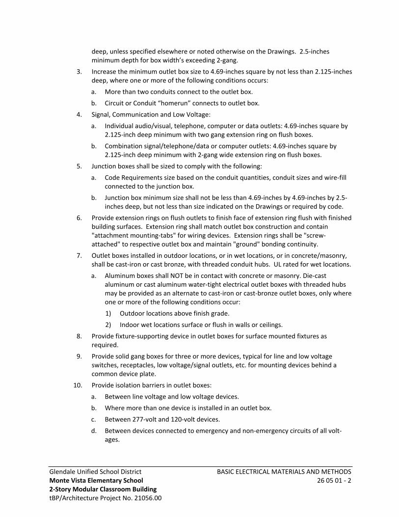
Glendale Unified School DistrictMonte Vista Elementary School 2-Story Modular Classroom BuildingtBP/Architecture Project No. 21056.00
BASIC ELECTRICAL MATERIALS AND METHODS26 05 01 - 2
deep, unless specified elsewhere or noted otherwise on the Drawings. 2.5-inches minimum depth for box width’s exceeding 2-gang.
3. Increase the minimum outlet box size to 4.69-inches square by not less than 2.125-inches deep, where one or more of the following conditions occurs:
a. More than two conduits connect to the outlet box.
b. Circuit or Conduit “homerun” connects to outlet box.
4. Signal, Communication and Low Voltage:
a. Individual audio/visual, telephone, computer or data outlets: 4.69-inches square by 2.125-inch deep minimum with two gang extension ring on flush boxes.
b. Combination signal/telephone/data or computer outlets: 4.69-inches square by 2.125-inch deep minimum with 2-gang wide extension ring on flush boxes.
5. Junction boxes shall be sized to comply with the following:
a. Code Requirements size based on the conduit quantities, conduit sizes and wire-fill connected to the junction box.
b. Junction box minimum size shall not be less than 4.69-inches by 4.69-inches by 2.5-inches deep, but not less than size indicated on the Drawings or required by code.
6. Provide extension rings on flush outlets to finish face of extension ring flush with finished building surfaces. Extension ring shall match outlet box construction and contain "attachment mounting-tabs" for wiring devices. Extension rings shall be "screw-attached" to respective outlet box and maintain "ground" bonding continuity.
7. Outlet boxes installed in outdoor locations, or in wet locations, or in concrete/masonry, shall be cast-iron or cast bronze, with threaded conduit hubs. UL rated for wet locations.
a. Aluminum boxes shall NOT be in contact with concrete or masonry. Die-cast aluminum or cast aluminum water-tight electrical outlet boxes with threaded hubs may be provided as an alternate to cast-iron or cast-bronze outlet boxes, only where one or more of the following conditions occur:
1) Outdoor locations above finish grade.
2) Indoor wet locations surface or flush in walls or ceilings.
8. Provide fixture-supporting device in outlet boxes for surface mounted fixtures as required.
9. Provide solid gang boxes for three or more devices, typical for line and low voltage switches, receptacles, low voltage/signal outlets, etc. for mounting devices behind a common device plate.
10. Provide isolation barriers in outlet boxes:
a. Between line voltage and low voltage devices.
b. Where more than one device is installed in an outlet box.
c. Between 277-volt and 120-volt devices.
d. Between devices connected to emergency and non-emergency circuits of all volt-ages.
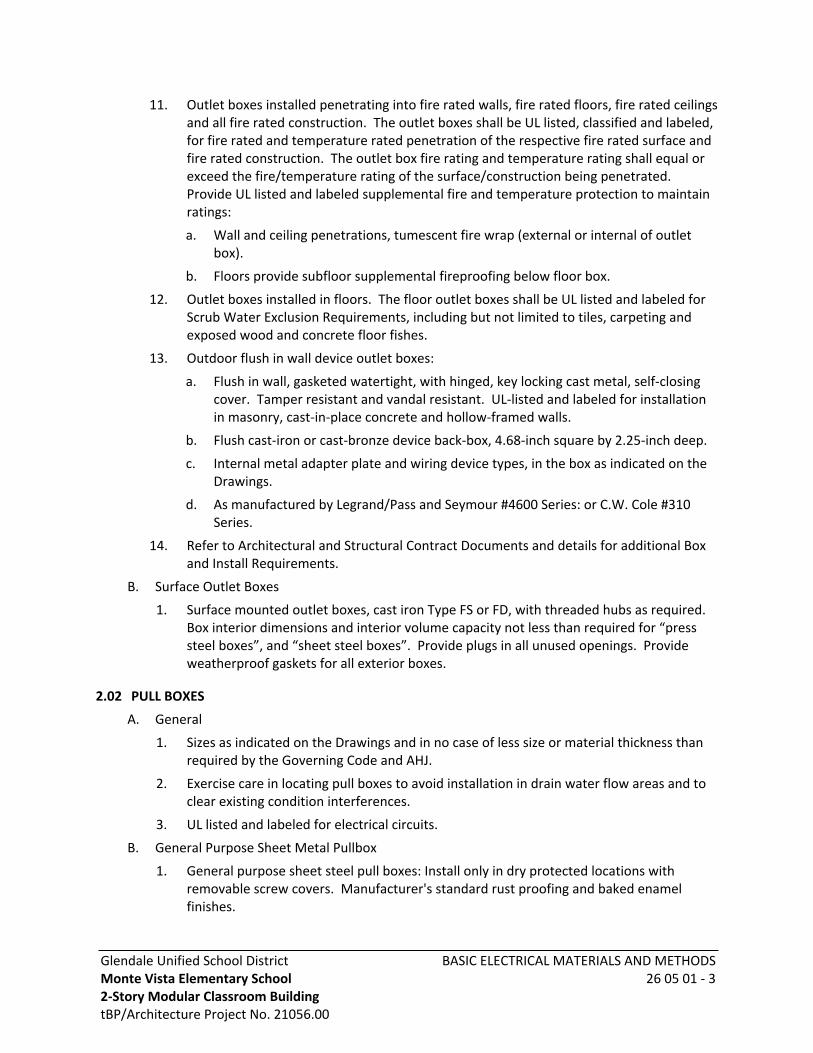
Glendale Unified School DistrictMonte Vista Elementary School 2-Story Modular Classroom BuildingtBP/Architecture Project No. 21056.00
BASIC ELECTRICAL MATERIALS AND METHODS26 05 01 - 3
11. Outlet boxes installed penetrating into fire rated walls, fire rated floors, fire rated ceilings and all fire rated construction. The outlet boxes shall be UL listed, classified and labeled, for fire rated and temperature rated penetration of the respective fire rated surface and fire rated construction. The outlet box fire rating and temperature rating shall equal or exceed the fire/temperature rating of the surface/construction being penetrated. Provide UL listed and labeled supplemental fire and temperature protection to maintain ratings:
a. Wall and ceiling penetrations, tumescent fire wrap (external or internal of outlet box).
b. Floors provide subfloor supplemental fireproofing below floor box.
12. Outlet boxes installed in floors. The floor outlet boxes shall be UL listed and labeled for Scrub Water Exclusion Requirements, including but not limited to tiles, carpeting and exposed wood and concrete floor fishes.
13. Outdoor flush in wall device outlet boxes:
a. Flush in wall, gasketed watertight, with hinged, key locking cast metal, self-closing cover. Tamper resistant and vandal resistant. UL-listed and labeled for installation in masonry, cast-in-place concrete and hollow-framed walls.
b. Flush cast-iron or cast-bronze device back-box, 4.68-inch square by 2.25-inch deep.
c. Internal metal adapter plate and wiring device types, in the box as indicated on the Drawings.
d. As manufactured by Legrand/Pass and Seymour #4600 Series: or C.W. Cole #310 Series.
14. Refer to Architectural and Structural Contract Documents and details for additional Box and Install Requirements.
B. Surface Outlet Boxes
1. Surface mounted outlet boxes, cast iron Type FS or FD, with threaded hubs as required. Box interior dimensions and interior volume capacity not less than required for “press steel boxes”, and “sheet steel boxes”. Provide plugs in all unused openings. Provide weatherproof gaskets for all exterior boxes.
2.02 PULL BOXES
A. General
1. Sizes as indicated on the Drawings and in no case of less size or material thickness than required by the Governing Code and AHJ.
2. Exercise care in locating pull boxes to avoid installation in drain water flow areas and to clear existing condition interferences.
3. UL listed and labeled for electrical circuits.
B. General Purpose Sheet Metal Pullbox
1. General purpose sheet steel pull boxes: Install only in dry protected locations with removable screw covers. Manufacturer's standard rust proofing and baked enamel finishes.
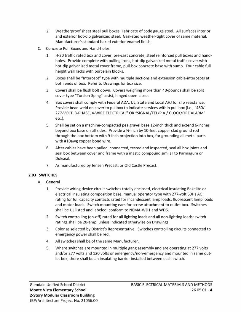
Glendale Unified School DistrictMonte Vista Elementary School 2-Story Modular Classroom BuildingtBP/Architecture Project No. 21056.00
BASIC ELECTRICAL MATERIALS AND METHODS26 05 01 - 4
2. Weatherproof sheet steel pull boxes: Fabricate of code gauge steel. All surfaces interior and exterior hot-dip galvanized steel. Gasketed weather-tight cover of same material. Manufacturer's standard baked exterior enamel finish.
C. Concrete Pull Boxes and Hand-holes
1. H-20 traffic rated box and cover, pre-cast concrete, steel reinforced pull boxes and hand-holes. Provide complete with pulling irons, hot-dip galvanized metal traffic cover with hot-dip galvanized metal cover frame, pull-box concrete base with sump. Four cable full height wall racks with porcelain blocks.
2. Boxes shall be “Intercept” type with multiple sections and extension cable-intercepts at both ends of box. Refer to Drawings for box size.
3. Covers shall be flush bolt down. Covers weighing more than 40-pounds shall be split cover type “Torsion-Sping” assist, hinged open-close.
4. Box covers shall comply with Federal ADA, UL, State and Local AHJ for slip resistance. Provide bead weld on cover to pullbox to indicate services within pull box (i.e., "480/ 277-VOLT, 3-PHASE, 4-WIRE ELECTRICAL" OR “SIGNAL/TEL/P.A./ CLOCK/FIRE ALARM" etc.).
5. Shall be set on a machine-compacted pea gravel base 12-inch thick and extend 6-inches beyond box base on all sides. Provide a ¾-inch by 10-feet copper clad ground rod through the box bottom with 9-inch projection into box, for grounding all metal parts with #10awg copper bond wire.
6. After cables have been pulled, connected, tested and inspected, seal all box joints and seal box between cover and frame with a mastic compound similar to Parmagum or Dukseal.
7. As manufactured by Jensen Precast, or Old Castle Precast.
2.03 SWITCHES
A. General
1. Provide wiring device circuit switches totally enclosed, electrical insulating Bakelite or electrical insulating composition base, manual operator type with 277-volt 60Hz AC rating for full capacity contacts rated for incandescent lamp loads, fluorescent lamp loads and motor loads. Switch mounting ears for screw attachment to outlet box. Switches shall be UL listed and labeled; conform to NEMA-WD1 and WD6.
2. Switch controlling (on-off) rated for all lighting loads and all non-lighting loads; switch ratings shall be 20-amp, unless indicated otherwise on Drawings.
3. Color as selected by District’s Representative. Switches controlling circuits connected to emergency power shall be red.
4. All switches shall be of the same Manufacturer.
5. Where switches are mounted in multiple gang assembly and are operating at 277 volts and/or 277 volts and 120 volts or emergency/non-emergency and mounted in same out-let box, there shall be an insulating barrier installed between each switch.
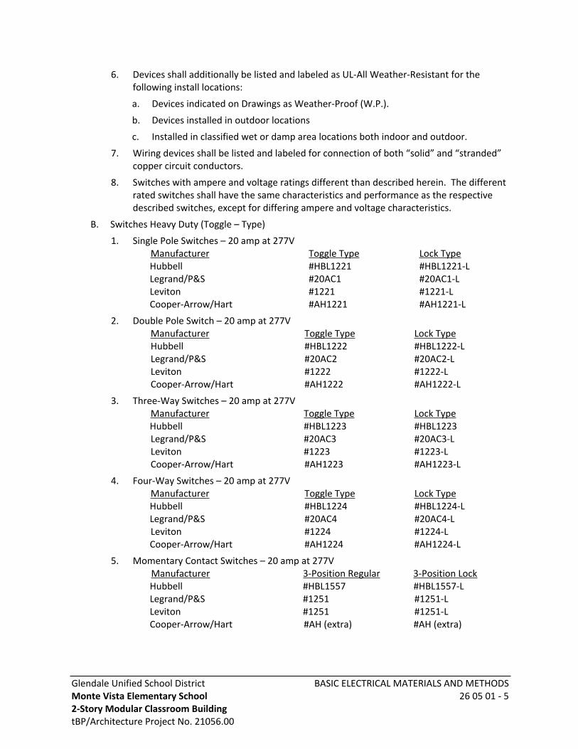
Glendale Unified School DistrictMonte Vista Elementary School 2-Story Modular Classroom BuildingtBP/Architecture Project No. 21056.00
BASIC ELECTRICAL MATERIALS AND METHODS26 05 01 - 5
6. Devices shall additionally be listed and labeled as UL-All Weather-Resistant for the following install locations:
a. Devices indicated on Drawings as Weather-Proof (W.P.).
b. Devices installed in outdoor locations
c. Installed in classified wet or damp area locations both indoor and outdoor.
7. Wiring devices shall be listed and labeled for connection of both “solid” and “stranded” copper circuit conductors.
8. Switches with ampere and voltage ratings different than described herein. The different rated switches shall have the same characteristics and performance as the respective described switches, except for differing ampere and voltage characteristics.
B. Switches Heavy Duty (Toggle – Type)
1. Single Pole Switches – 20 amp at 277VManufacturer Toggle Type Lock TypeHubbell #HBL1221 #HBL1221-LLegrand/P&S #20AC1 #20AC1-LLeviton #1221 #1221-LCooper-Arrow/Hart #AH1221 #AH1221-L
2. Double Pole Switch – 20 amp at 277VManufacturer Toggle Type Lock TypeHubbell #HBL1222 #HBL1222-LLegrand/P&S #20AC2 #20AC2-LLeviton #1222 #1222-LCooper-Arrow/Hart #AH1222 #AH1222-L
3. Three-Way Switches – 20 amp at 277VManufacturer Toggle Type Lock TypeHubbell #HBL1223 #HBL1223Legrand/P&S #20AC3 #20AC3-LLeviton #1223 #1223-LCooper-Arrow/Hart #AH1223 #AH1223-L
4. Four-Way Switches – 20 amp at 277VManufacturer Toggle Type Lock TypeHubbell #HBL1224 #HBL1224-LLegrand/P&S #20AC4 #20AC4-LLeviton #1224 #1224-LCooper-Arrow/Hart #AH1224 #AH1224-L
5. Momentary Contact Switches – 20 amp at 277VManufacturer 3-Position Regular 3-Position LockHubbell #HBL1557 #HBL1557-LLegrand/P&S #1251 #1251-LLeviton #1251 #1251-LCooper-Arrow/Hart #AH (extra) #AH (extra)
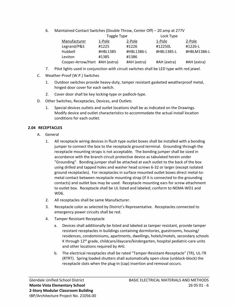
Glendale Unified School DistrictMonte Vista Elementary School 2-Story Modular Classroom BuildingtBP/Architecture Project No. 21056.00
BASIC ELECTRICAL MATERIALS AND METHODS26 05 01 - 6
6. Maintained Contact Switches (Double Throw, Center Off) – 20 amp at 277V Toggle Type Lock Type
Manufacturer 1-Pole 2-Pole 1-Pole 2-PoleLegrand/P&S #1225 #1226 #12250L #1226-LHubbell #HBL1385 #HBL1386-L #HBL1385-L #HBLM1386-LLeviton #1385 #1386Cooper-Arrow/Hart #AH (extra) #AH (extra) #AH (extra) #AH (extra)
7. Pilot lights used in conjunction with circuit switches shall be LED type with red jewel.
C. Weather-Proof (W.P.) Switches
1. Outdoor switches provide heavy-duty, tamper resistant gasketed weatherproof metal, hinged door cover for each switch.
2. Cover door shall be key locking-type or padlock-type.
D. Other Switches, Receptacles, Devices, and Outlets
1. Special devices outlets and outlet locations shall be as indicated on the Drawings. Modify device and outlet characteristics to accommodate the actual install location conditions for each outlet.
2.04 RECEPTACLES
A. General
1. All receptacle wiring devices in flush type outlet boxes shall be installed with a bonding jumper to connect the box to the receptacle ground terminal. Grounding through the receptacle mounting straps is not acceptable. The bonding jumper shall be sized in accordance with the branch circuit protective device as tabulated herein under "Grounding". Bonding jumper shall be attached at each outlet to the back of the box using drilled and tapped holes and washer head screws 6-32 or larger (except isolated ground receptacles). For receptacles in surface mounted outlet boxes direct metal-to-metal contact between receptacle mounting strap (if it is connected to the grounding contacts) and outlet box may be used. Receptacle mounting ears for screw attachment to outlet box. Receptacle shall be UL listed and labeled; conform to NEMA-WD1 and WD6.
2. All receptacles shall be same Manufacturer.
3. Receptacle color as selected by District’s Representative. Receptacles connected to emergency power circuits shall be red.
4. Tamper Resistant Receptacle
a. Devices shall additionally be listed and labeled as tamper resistant, provide tamper resistant receptacles in buildings containing dormitories, guestrooms, housing/ residences, condominiums, apartments, dwellings, hotels/motels, secondary schools K through 12th grade, childcare/daycare/kindergarten, hospital pediatric-care units and other locations required by AHJ.
b. The electrical receptacles shall be rated “Tamper-Resistant-Receptacle” (TR), UL-TR (RTRT). Spring loaded shutters shall automatically open-close (unblock-block) the receptacle slots when the plug-in (cap) insertion and removal occurs.
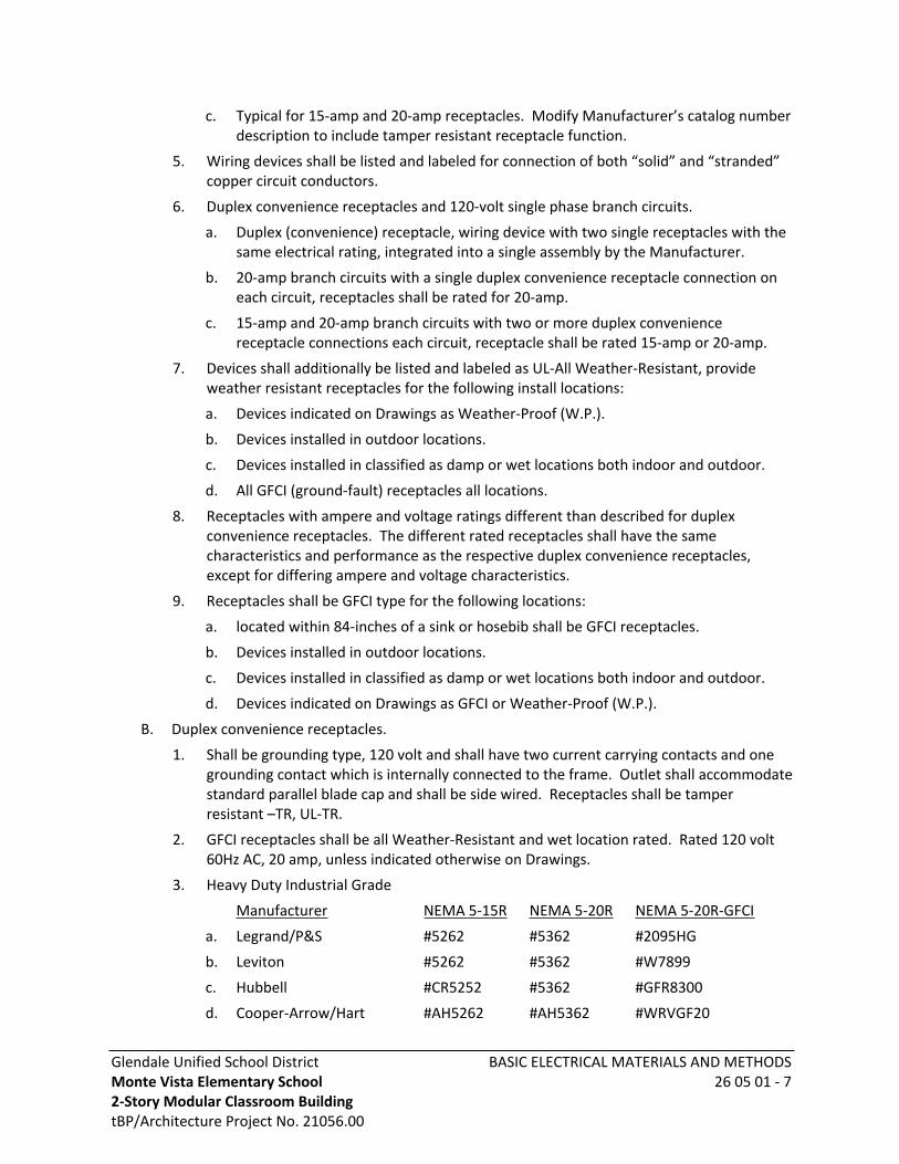
Glendale Unified School DistrictMonte Vista Elementary School 2-Story Modular Classroom BuildingtBP/Architecture Project No. 21056.00
BASIC ELECTRICAL MATERIALS AND METHODS26 05 01 - 7
c. Typical for 15-amp and 20-amp receptacles. Modify Manufacturer’s catalog number description to include tamper resistant receptacle function.
5. Wiring devices shall be listed and labeled for connection of both “solid” and “stranded” copper circuit conductors.
6. Duplex convenience receptacles and 120-volt single phase branch circuits.
a. Duplex (convenience) receptacle, wiring device with two single receptacles with the same electrical rating, integrated into a single assembly by the Manufacturer.
b. 20-amp branch circuits with a single duplex convenience receptacle connection on each circuit, receptacles shall be rated for 20-amp.
c. 15-amp and 20-amp branch circuits with two or more duplex convenience receptacle connections each circuit, receptacle shall be rated 15-amp or 20-amp.
7. Devices shall additionally be listed and labeled as UL-All Weather-Resistant, provide weather resistant receptacles for the following install locations:
a. Devices indicated on Drawings as Weather-Proof (W.P.).
b. Devices installed in outdoor locations.
c. Devices installed in classified as damp or wet locations both indoor and outdoor.
d. All GFCI (ground-fault) receptacles all locations.
8. Receptacles with ampere and voltage ratings different than described for duplex convenience receptacles. The different rated receptacles shall have the same characteristics and performance as the respective duplex convenience receptacles, except for differing ampere and voltage characteristics.
9. Receptacles shall be GFCI type for the following locations:
a. located within 84-inches of a sink or hosebib shall be GFCI receptacles.
b. Devices installed in outdoor locations.
c. Devices installed in classified as damp or wet locations both indoor and outdoor.
d. Devices indicated on Drawings as GFCI or Weather-Proof (W.P.).
B. Duplex convenience receptacles.
1. Shall be grounding type, 120 volt and shall have two current carrying contacts and one grounding contact which is internally connected to the frame. Outlet shall accommodate standard parallel blade cap and shall be side wired. Receptacles shall be tamper resistant –TR, UL-TR.
2. GFCI receptacles shall be all Weather-Resistant and wet location rated. Rated 120 volt 60Hz AC, 20 amp, unless indicated otherwise on Drawings.
3. Heavy Duty Industrial Grade
Manufacturer NEMA 5-15R NEMA 5-20R NEMA 5-20R-GFCI
a. Legrand/P&S #5262 #5362 #2095HG
b. Leviton #5262 #5362 #W7899
c. Hubbell #CR5252 #5362 #GFR8300
d. Cooper-Arrow/Hart #AH5262 #AH5362 #WRVGF20

Glendale Unified School DistrictMonte Vista Elementary School 2-Story Modular Classroom BuildingtBP/Architecture Project No. 21056.00
BASIC ELECTRICAL MATERIALS AND METHODS26 05 01 - 8
C. Weatherproof (W.P.) Receptacle
1. Outdoor receptacles shall be duplex convenience GFCI type rated 20-amp 120 Volt 60Hz AC weatherproof, GFCI, unless indicated otherwise on Drawings. Test-reset buttons and visual pilot.
2. GFCI receptacles shall be wet location and Weather-Resistant rated weatherproof, gasketed, key locking tamper resistant, wet location.
3. Outdoor, flush mount outlet with hinged, key-locking, weather-proof cover (CEC/NEC – 406.8 compliant). As manufactured by Pass and Seymour/Legrand #4600 Series; or C.W. Cole #310 Series.
4. On exposed conduit runs, provide weatherproof ground fault circuit interrupter type GFCI receptacles installed in "FS" condulet watertight cast metal body, with weather-proof spring door type covers, gasket watertight. Door shall be key locking-type or pad-lock-type.
D. Other switches, receptacles, devices, and outlets.
1. Special devices, outlets and outlet locations shall be as indicated on the Drawings. Modify device and outlet characteristics to accommodate the actual install location conditions for each outlet.
2.05 PLATES
A. Metal cover plates for devices
1. Provide cover plates for every switch, receptacle, telephone, computer, television and other device outlets. All plates shall be 0.040-inch stainless steel, Type 302 alloy composed of 18% chromium and 8% nickel. Plates shall be manufactured by P&S, Hubbell, Leviton or General Electric.
B. Residential location project non-metal cover plates for devices.
1. Provide plates for every switch, receptacle, telephone, computer, television, and other device outlets. Non-metallic, heavy-duty, high-abuse and high-impact resistant plates. Plates shall be same Manufacturer as the respective wiring device.
2.06 VANDAL-PROOF FASTENINGS
Provide approved vandal proof type screws, bolts, nuts where exposed to sight throughout the project. Screws for such items as switch plates, receptacle plates, fixtures, communications equipment, fire alarm, blank covers, wall and ceiling plates to be spanner head stainless steel, tamperproof type. Provide District with six screwdrivers for this type.
2.07 STRUCTURAL AND MISCELLANEOUS STEEL
Structural and miscellaneous steel used in connection with electrical work and located out-of-doors or in damp locations, shall be hot dip galvanized unless otherwise specified. Included are underground pull box covers and similar electrical items. Galvanizing averages 2.0 ounce per square foot and conforms to ASTM A123.
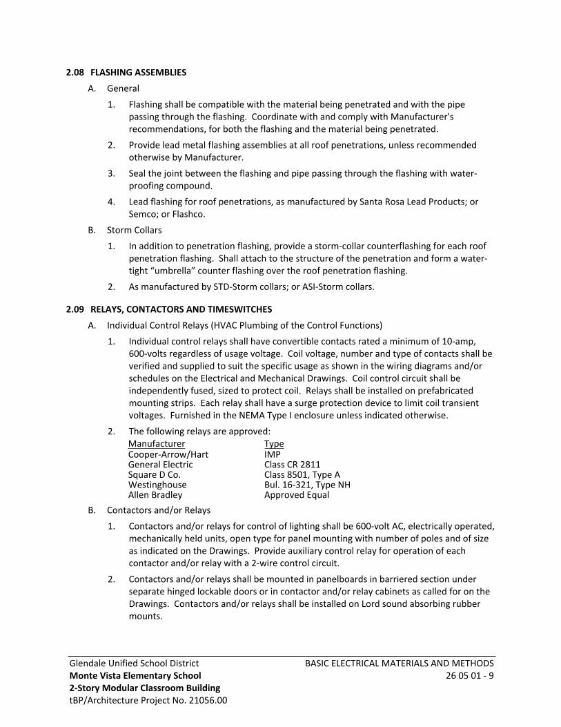
Glendale Unified School DistrictMonte Vista Elementary School 2-Story Modular Classroom BuildingtBP/Architecture Project No. 21056.00
BASIC ELECTRICAL MATERIALS AND METHODS26 05 01 - 9
2.08 FLASHING ASSEMBLIES
A. General
1. Flashing shall be compatible with the material being penetrated and with the pipe passing through the flashing. Coordinate with and comply with Manufacturer's recommendations, for both the flashing and the material being penetrated.
2. Provide lead metal flashing assemblies at all roof penetrations, unless recommended otherwise by Manufacturer.
3. Seal the joint between the flashing and pipe passing through the flashing with water-proofing compound.
4. Lead flashing for roof penetrations, as manufactured by Santa Rosa Lead Products; or Semco; or Flashco.
B. Storm Collars
1. In addition to penetration flashing, provide a storm-collar counterflashing for each roof penetration flashing. Shall attach to the structure of the penetration and form a water-tight “umbrella” counter flashing over the roof penetration flashing.
2. As manufactured by STD-Storm collars; or ASI-Storm collars.
2.09 RELAYS, CONTACTORS AND TIMESWITCHES
A. Individual Control Relays (HVAC Plumbing of the Control Functions)
1. Individual control relays shall have convertible contacts rated a minimum of 10-amp, 600-volts regardless of usage voltage. Coil voltage, number and type of contacts shall be verified and supplied to suit the specific usage as shown in the wiring diagrams and/or schedules on the Electrical and Mechanical Drawings. Coil control circuit shall be independently fused, sized to protect coil. Relays shall be installed on prefabricated mounting strips. Each relay shall have a surge protection device to limit coil transient voltages. Furnished in the NEMA Type I enclosure unless indicated otherwise.
2. The following relays are approved:Manufacturer TypeCooper-Arrow/Hart IMPGeneral Electric Class CR 2811Square D Co. Class 8501, Type AWestinghouse Bul. 16-321, Type NHAllen Bradley Approved Equal
B. Contactors and/or Relays
1. Contactors and/or relays for control of lighting shall be 600-volt AC, electrically operated, mechanically held units, open type for panel mounting with number of poles and of size as indicated on the Drawings. Provide auxiliary control relay for operation of each contactor and/or relay with a 2-wire control circuit.
2. Contactors and/or relays shall be mounted in panelboards in barriered section under separate hinged lockable doors or in contactor and/or relay cabinets as called for on the Drawings. Contactors and/or relays shall be installed on Lord sound absorbing rubber mounts.
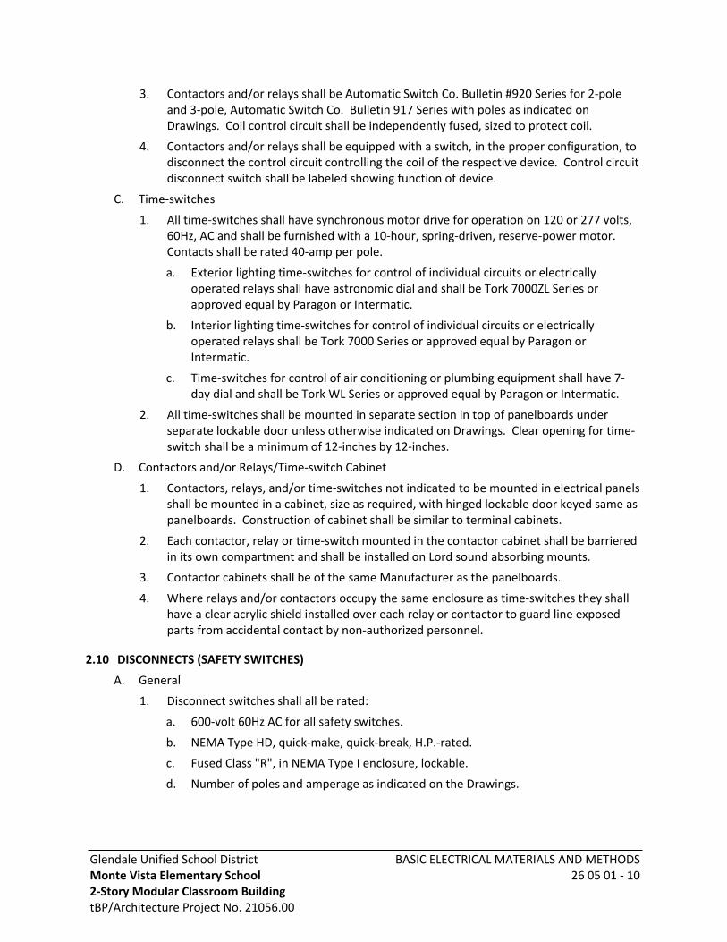
Glendale Unified School DistrictMonte Vista Elementary School 2-Story Modular Classroom BuildingtBP/Architecture Project No. 21056.00
BASIC ELECTRICAL MATERIALS AND METHODS26 05 01 - 10
3. Contactors and/or relays shall be Automatic Switch Co. Bulletin #920 Series for 2-pole and 3-pole, Automatic Switch Co. Bulletin 917 Series with poles as indicated on Drawings. Coil control circuit shall be independently fused, sized to protect coil.
4. Contactors and/or relays shall be equipped with a switch, in the proper configuration, to disconnect the control circuit controlling the coil of the respective device. Control circuit disconnect switch shall be labeled showing function of device.
C. Time-switches
1. All time-switches shall have synchronous motor drive for operation on 120 or 277 volts, 60Hz, AC and shall be furnished with a 10-hour, spring-driven, reserve-power motor. Contacts shall be rated 40-amp per pole.
a. Exterior lighting time-switches for control of individual circuits or electrically operated relays shall have astronomic dial and shall be Tork 7000ZL Series or approved equal by Paragon or Intermatic.
b. Interior lighting time-switches for control of individual circuits or electrically operated relays shall be Tork 7000 Series or approved equal by Paragon or Intermatic.
c. Time-switches for control of air conditioning or plumbing equipment shall have 7-day dial and shall be Tork WL Series or approved equal by Paragon or Intermatic.
2. All time-switches shall be mounted in separate section in top of panelboards under separate lockable door unless otherwise indicated on Drawings. Clear opening for time-switch shall be a minimum of 12-inches by 12-inches.
D. Contactors and/or Relays/Time-switch Cabinet
1. Contactors, relays, and/or time-switches not indicated to be mounted in electrical panels shall be mounted in a cabinet, size as required, with hinged lockable door keyed same as panelboards. Construction of cabinet shall be similar to terminal cabinets.
2. Each contactor, relay or time-switch mounted in the contactor cabinet shall be barriered in its own compartment and shall be installed on Lord sound absorbing mounts.
3. Contactor cabinets shall be of the same Manufacturer as the panelboards.
4. Where relays and/or contactors occupy the same enclosure as time-switches they shall have a clear acrylic shield installed over each relay or contactor to guard line exposed parts from accidental contact by non-authorized personnel.
2.10 DISCONNECTS (SAFETY SWITCHES)
A. General
1. Disconnect switches shall all be rated:
a. 600-volt 60Hz AC for all safety switches.
b. NEMA Type HD, quick-make, quick-break, H.P.-rated.
c. Fused Class "R", in NEMA Type I enclosure, lockable.
d. Number of poles and amperage as indicated on the Drawings.

Glendale Unified School DistrictMonte Vista Elementary School 2-Story Modular Classroom BuildingtBP/Architecture Project No. 21056.00
BASIC ELECTRICAL MATERIALS AND METHODS26 05 01 - 11
2. Provide internal neutral bus, ground-lug and conductor landing lugs, size to match conductors shown on Drawings. Switch access door shall be interlocked with switch to prevent access inside switch when switch is “on” closed position.
3. Where enclosure is indicated W.P. (Weather-Proof) switches shall be raintight NEMA Type HD and NEMA 3R enclosure, lockable.
4. Maximum voltage, current and horsepower rating clearly marked on the switch enclosure and switches having dual element fuses shall have rating indicated on the nameplate.
5. Switch and fuses ampere rating shall also comply with Manufacturer recommendation for the connected load.
2.11 CONCRETE WORK (ADDITIONAL REQUIREMENTS)
A. Portland Cement
1. ASTM C33- (latest revision), Type II, Low Alkali Cement. Composed of Portland cement, coarse aggregate, fine aggregate, and water.
a. Concrete for use as electrical equipment footings, lighting pole bases and equipment slabs on grade, concrete shall attain minimum 28-day compressive strength of 4000psi, using not less than 5.75 sacks of cement per cubic yard of wet concrete.
b. Concrete for underground duct/conduit encasement, the minimum 28-day compressive strength shall be 2000 psi. Provide a minimum of 10-pounds of red oxide concrete coloring per yard of concrete.
c. Mix shall obtain a 6-inches slump, measured with standard slump cone per ASTM C143/C143M (latest revision).
2. Coarse Aggregate: Uniformly graded between maximum size not over 1½-inch and not less than ¾-inch and minimum Size #4, crushed rock or washed gravel. For concrete encased conduit only, maximum aggregate size shall be ½-inch.
3. Fine Aggregate: Clean, natural washed sand of hard and durable particles varying from fine to particles passing ⅜-inch screen, of which at least 12% shall pass fifty mesh screens.
B. Water: Clean and free from deleterious quantities of acids, alkalis, salts, or organic materials.
C. Reinforcement
1. Bars: Intermediate Grade Steel conforming to ASTM A615/A615M grade 60, with pattern deformations.
2. Welded Wire Fabric: ASTM A185/A185M.
3. Bending: Conform to Requirements of ACI 318.
D. Form Material: For exposed work, use PS 1-66 "B-B Concrete Form" plywood forms, or equal. Elsewhere, forms may be plywood, metal, or 1-inch by 6-inch boards. Forms for round lighting pole bases shall be sono-tube.

Glendale Unified School DistrictMonte Vista Elementary School 2-Story Modular Classroom BuildingtBP/Architecture Project No. 21056.00
BASIC ELECTRICAL MATERIALS AND METHODS26 05 01 - 12
2.12 WIREWAY
A. General:
Unobstructed lay in type, metal wireway, fittings and connectors UL listed for use as wireway and auxiliary gutter. Length, elbows and "T-S" as shown on Drawings. Minimum cross-section size 4-inches by 4-inches, but not less than shown on the Drawings. Suitable for mounting in any position orientation.
B. Construction:
1. Minimum metal gauge shall not be less than 14 gages.
2. Cover shall be hinged entire length of cover. Cover shall be held in the closed position with bolts and nuts.
3. Provide spring nuts on all hardware fastener penetrations into the interior of the wireway to protect against wire insulation damage.
4. The inside of 90-degree corners in the wireway shall be a 45-degree bevel.
5. Grounding continuity between wireway sections and fittings shall be continuous the entire length of the wireway.
C. Finish:
1. Indoor non-raintight, rust inhibitor phosphatizing base coating and baked enamel finish, Manufacturer's standard color.
2. Raintight outdoor-galvanized metal, with corrosion resistant phosphate primer and baked enamel finish, Manufacturer's standard color, NEMA 3R construction.
3. All hardware shall be plated to prevent corrosion.
PART 3 - EXECUTION
3.01 GROUNDING (ADDITIONAL REQUIREMENTS)
A. Grounding shall be executed in accordance with all applicable Codes and Regulations, both of the State of California and Local authorities having jurisdiction.
B. The neutral of each transformer shall be grounded by individual separate ground conductors in individual conduits as follows:
1. Conductor and conduit shall be grounded to building main ground bus.
2. Conductor and conduit shall be grounded to nearest available effectively grounded building structural steel member or grounded metal cold water pipe.
C. The transformer neutral ground conductors for secondary side of the transformers shall be copper and shall be sized according to the following table:
Secondary Total EquivalentSize Copper
Neutral Ground Wire Size Copper
#2 or smaller #6-1-inch conduit1 or 1/0 #4-1-inch conduit2/0 or 3/0 #2-1¼-inch conduit4/0 thru 350 MCM #1-1¼-inch conduitOver 350 MCM thru 600 MCM 2/0-1½-inch conduitOver 600 MCM thru 1100 MCM 3/0-1½-inch conduit

Glendale Unified School DistrictMonte Vista Elementary School 2-Story Modular Classroom BuildingtBP/Architecture Project No. 21056.00
BASIC ELECTRICAL MATERIALS AND METHODS26 05 01 - 13
Over 1100 MCM 4/0-2-inch conduitD. Each pullbox or any other enclosure in which several ground wires are terminated shall be
equipped with a ground bus secured to the interior of the enclosure. The bus shall have a separate lug for each ground conductor. No more than one conductor shall be installed per lug.
E. The maximum resistance to ground shall not exceed 5 ohms.
3.02 OUTLET AND JUNCTION BOXES
A. General:
1. Accurately place boxes and securely fastens to structural members. Where outlets are shown at same location but at different mounting heights, install outlets in one vertical line. Where outlets are shown at same location and mounting height, mount outlets as close together in a horizontal row as possible. Where the outlet boxes for switches and receptacles are shown at the same location and mounting height, mount in common outlet box with barriers between devices. Provide single piece multi-gang cover plate for close mounted outlet boxes. Where switches are shown on wall adjacent to hinge side of doors, box shall be installed to clear door when door is fully opened.
2. Flush mounted boxes shall be attached to not less than two parallel studs or structure members by means of metal supports. The supports shall span between and attach to the structure members.
3. Boxes above accessible ceilings shall be attached to structural members. Where boxes are suspended, they shall be supported independently of conduit system by means of hanger rods and/or preformed steel channels. Boxes shall be supported independently of all piping, ductwork, equipment, ceiling hanger wires and suspended ceiling grid system.
4. Surface mounted outlets shall be attached to concrete or masonry walls by means of expansion shields.
5. Floor boxes shall be installed level with finish floor and within adjustable limits of floor ring. Where outlets are shown at same or adjacent location, use multi-gang boxes.
a. Provide cut-outs in the sub-floor assembly, to accept the recess depth of each electrical floor box. Provide added “fire-proof” applications on the bottom of each floor box location extending through the sub-floor. The “fire-proof” application shall be equal to the floor fire-assembly withstand rating.
b. Poke-thru floor outlets, core drill floor for installation of poke-thru. Install “split-box” in the ceiling space of the floor below. If the ceiling space of the floor below is not accessible ceiling type (lift-out), then provide 12-inches round removable fire-rated stainless steel access panel and trim-ring in the finish ceiling for hand-access to poke-thru “split-box” above the ceiling.
6. Outlet Box Horizontal and Vertical Separation: Outlet boxes and device outlet rings installed flush in walls shall be horizontally and vertically separated by not less than 24-inches (edge of box to edge of box) from device outlet boxes and rings in common wall surfaces located on the opposite (back) side of the same wall.
Glendale Unified School DistrictMonte Vista Elementary School 2-Story Modular Classroom BuildingtBP/Architecture Project No. 21056.00
BASIC ELECTRICAL MATERIALS AND METHODS26 05 01 - 14
a. Where the separation cannot be maintained, provide a solid backing behind and completely enclosing each outlet box.
b. The backing shall extend the width of the wall cavity (i.e., between "studs" or masonry cells) behind the box and 12-inches above and below the outlet box centerline, completely enclosing the outlet box.
c. The backing shall consist of the following:
1) ⅝-inch thick gypsum board anchored in place for "stud" wall construction.
2) Solid "mortar" to completely fill the outlet box "cell" behind the box in masonry construction.
7. Provide metal outlet box for each device. Install devices in metal outlet boxes. Typical for all wiring devices including, switches, receptacles, line voltage devices, and low volt-age/signal system devices.
B. Fire Wrap:
1. In fire rated walls and ceilings provide fire rated "box-wrap" around the outside of each outlet box placed in fire rated wall or ceiling. Install the fire wrap on exterior of box inside the wall or ceiling, to maintain the fire rating of wall or ceiling with the installed outlet boxes.
3.03 SWITCHES AND RECEPTACLES-DEVICES
A. General
1. Provide outlet boxes for all devices, switches, receptacles, both line-voltage and low-volt-age.
2. Devices installed in wireways shall be installed flush in wireway assembly.
3. Install and screw attach devices into outlet boxes and wireways.
4. Provide ground circuit connections to all devices.
5. Provide branch circuit connections to all devices.
6. Provide testing and commissioning for proper operation and phase/ground connectors.
a. Test each GFCI devices after installation and circuit connection is complete.
b. Test all devices for correct polarity and proper electrical energization.
7. Install and adjust all coverplates to be flush and level, with correct device identification.
8. Were one or more device occurring at the proximity with other similar devices, all of the devices shall be “granged” under one common coverplate as follows:
a. Duplex convenience receptacles with other proximity (within 18-inches) duplex convenience receptacles.
b. Lighting control switches not exceeding 20-amp switch rating with other proximity (within 18-inches) similar switches.
B. Line-voltage Plug-In Type Receptacle Installation Orientation:
1. The “ground-pin” shall face “up” at the receptacle top location (double duplex) 4-plex, individual and vertically mounted individual duplex receptacles.

Glendale Unified School DistrictMonte Vista Elementary School 2-Story Modular Classroom BuildingtBP/Architecture Project No. 21056.00
BASIC ELECTRICAL MATERIALS AND METHODS26 05 01 - 15
2. The “neutral-blade” shall face “up” at the receptacle top location on horizontally mounted duplex receptacles.
3.04 CONCRETE WORK
A. Form:
1. Space forms properly with spreaders and securely tie together. Do not use twisted wire form ties. Keep forms wet to prevent joints from opening up before concrete is placed. Replace improper construction as directed. Do not use wood inside forms.
2. Build in and set all anchors, dowels, bolts, sleeves, iron frames, expansion joints and other materials required for the Electrical Work. Place all items carefully, true, straight, plumb, and even.
3. Carefully remove all exposed forms. Cut nails and tie wires below face of concrete and fill all holes. Rubbish will not be allowed to remain in, under, or around concrete.
B. Mixing: Use batch machine mixer of approved type. After ingredients are in mixer, mix for at least 1½-minutes.
C. Transit Mixing: In lieu of mixing at site, transit mixing may be used if rate of delivery, haul time, mixing time, and hopper capacity is such that concrete delivered will be placed in forms within 90-minutes from time of introduction of cement and water to mixer.
D. Placing of Concrete
1. Before placing concrete, remove wood, rubbish, vegetable matter and loose material from inside forms. Thoroughly wet down wood forms to close joints.
2. Clean reinforcement; remove paint, loose rust, scale and foreign material. Bars with bends not called for will be rejected. Hold securely in place to prevent displacement. Lap bar splices 24-diameters, min; lap fabric one-mesh minimum. Tie intersections, corners, splices with 16-gallon annealed wire, or as otherwise called for.
3. Place concrete immediately after mixing. Do not use concrete that has begun to set; no tempering will be allowed. If chuting is used, avoid segregation. In placing new concrete against existing concrete, use bonding agent per Manufacturer's directions.
4. Give careful and thorough attention to curing of concrete. Keep concrete and forms wet for a minimum of 10-days, after placing concrete.
E. Concrete Finish
1. Finish of Exposed Concrete: Horizontal surfaces, steel troweled monolithic finish; vertical surfaces, smooth and free of fins, holes, projection, etc.
2. Exposed lighting pole bases shall be filled, and sack finished to a smooth finish.
3.05 WIREWAY INSTALLATION
Wireway hangers shall provide clamp type, hanger rod type, direct bolted bracket type from ceiling or walls as indicated on the Drawings and required for field installation locations. Supports shall be installed a minimum of 5-feet on center.
END OF SECTION 26 05 01041921/212277
Glendale Unified School DistrictMonte Vista Elementary School 2-Story Modular Classroom BuildingtBP/Architecture Project No. 21056.00
CONDUIT AND WIRE26 05 30 - 1
SECTION 26 05 30CONDUIT AND WIRE
PART 1 - GENERAL
1.01 SCOPE
A. Work Included: All labor, materials, appliances, tools, equipment, facilities, transportation, and services necessary for and incidental to performing all operations in connection with furnishing, delivery and installation of the work of this Section, complete as shown on the Drawings and/or specified herein. Work includes, but is not necessarily limited to the following:
1. Examine all other Sections for work related to those other Sections and required to be included as work under this Section.
2. General Provisions and Requirements for electrical work.
1.02 SUBMITTALS (ADDITIONAL REQUIREMENTS)
A. Submit product data sheets for all wire, supports, conduit, fittings and splicing materials.
B. Submit material list for all conduit and conduit fittings.
C. Submit details and structural engineering calculations for conduit support systems.
PART 2 - PRODUCTS
2.01 CONDUIT
A. General
1. The interior surfaces of conduits and fittings shall be continuous and smooth, with a constant interior diameter. Conduits and conduit fittings shall provide conductor race-ways of fully enclosed circular cross section. The interior surfaces of conduits and fittings shall be without ridges, burrs irregularities or obstructions. Conduits and fittings of the same type shall be of the same uniform weight and thickness.
2. Type of conduit, type of conduit fittings and conduit supports shall be suitable for the conditions of use and the conditions of location of installation, based on the Manufacturer’s recommendations and based on applicable Codes.
3. All fittings for metal conduit shall be suitable for use as a grounding means, pursuant to the applicable Code Requirements. All metal conduit and metal conduit fittings shall provide 3 second duration ground fault current carrying ratings, when installed and connected to the respective conduit, as follows:
a. RMC and EMT conduit fittings.
1) 0.5 inch through 1.5 inch conduit/fitting size - 10,000 amp RMS.
2) 2.0 inch and larger conduit/fitting size - 20,000 amp RMS.
Glendale Unified School DistrictMonte Vista Elementary School 2-Story Modular Classroom BuildingtBP/Architecture Project No. 21056.00
CONDUIT AND WIRE26 05 30 - 2
b. FMC and LTFMC Conduit Fittings
1) 0.5 inch through 1.25-inch conduit/fitting size 1,000-amp RMS (without external bonding jumper).
2) 1.5 inch through 4.0-inch fitting size 10,000-amp RMS with bonding jumper.
4. Protective corrosion resistant finish for metal conduit fabricated from steel and metal conduit fittings fabricated from steel, shall be as follows:
a. Clean all metal surfaces (including metal threads) with acid bath “pickle” prior to coating, to remove dirt, oil and prepare surfaces for galvanizing.
b. Hot-dip galvanized zinc coating on all interior and exterior steel surfaces. Minimum finish zinc coating thickness shall not be less than 0.002 inches.
c. Threads shall be hot-dip zinc coated after machine fabrication.
d. Exterior metal surfaces shall be finished with clear organic polymer topcoat layer, after galvanizing.
e. The inner metal surfaces of conduit fittings shall be finished with a lubricating top-coat after galvanizing, to facilitate conductor pulling through the conduit/fitting.
5. Threads for metal conduit and metal conduit fittings shall be taper-pipe-thread, National Pipe Standards (NPS) and shall comply with ANSI-B1.20.1.
6. Metal conduit termination connector fittings shall be provided with a Manufacturer installed, insulating throat bushing inside the fitting. The bushing shall protect the wire conductor insulation from cutting, nicks and abrasion during conductor installation and electrical load “cycling” after installation is complete. The bushing shall comply with UL 94V-0 flammability.
7. Provide conduit bonding/grounding jumper from metal enclosures with “concentric ring” knockouts, to positively ground/bond each respective conduit(s) to the metal enclosure.
8. Metal conduit fittings connecting to PVC coated metal conduit shall be PVC coated to match the conduit.
9. The conduit and fittings shall be watertight and airtight without cracks and pinholes.
B. Rigid Metal Conduit (RMC)
1. Rigid metal, round tubing, machine threaded at both ends.
a. The conduit and conduit fittings shall comply with the Requirements for an equipment grounding conductor, pursuant to applicable Codes.
2. RMC raceway types shall be as follows:
a. Rigid Galvanized Steel conduit (RGS), minimum yield strength shall be 35,000 PSI. Shall comply with NEMA standard 5-19 (latest revision); ANSI C80.1 and ANSI-C80.4 (latest revision); UL 514-B and UL 6 (latest revisions); National Pipe Standard Specification (latest revision).
b. Intermediate steel conduit (IMC). Shall comply with NEMA Standard 5-19 (latest revision) ANSI-C80.6 (latest revision); UL 2142 (latest revision).
3. RMC fittings:
a. Fittings shall be compatible with RGS and IMC.
Glendale Unified School DistrictMonte Vista Elementary School 2-Story Modular Classroom BuildingtBP/Architecture Project No. 21056.00
CONDUIT AND WIRE26 05 30 - 3
b. Fittings shall be rated “liquid tight”.
c. Fittings imbedded in concrete shall be rated “liquid tight” and “concrete tight”.
d. Connectors and couplings for terminating, connecting, and coupling to RMC conduit shall be threaded metal.
e. Fittings shall comply with ANSI C80.4 and ANSI C33-84 (latest revision); NEMA FB1 (latest revision); UL 514 (latest revision).
f. Conduit seal fittings:
1) Conduit seals shall prevent the passage of gasses, liquids and vapors past the location of the seal installation in the conduit.
2) Conduit seals shall be suitable for installation in both vertical and horizontal conduit locations.
3) Conduit seals shall be visible and accessible for inspection after installation is complete.
4) Conduit seals shall be rated for the following locations:a) Wet locationsb) Classified hazardous location materials NEC Class 1 Division 1.c) Temperature ranges from 0 degrees centigrade through 90 degrees
centigrade.
5) Conduit seals, sealing compound and sealing compound dam shall be the products of the same Manufacturer.
4. RMC fittings as manufactured by:
a. For threaded enclosure, termination connection.
1) Thomas & Betts - 106 Series bonding locknut, 5302 Series sealing ring with stainless steel retainer.
b. For non-threaded enclosure, termination connector.
1) Thomas & Betts - 370 Series watertight threaded sealing hub, 106 Series threaded bonding locknut, Sta-Con Series enclosure bonding jumper and 3870 Series threaded ground bushing.
2) Emerson-OZ/Gedney-CHMT/CHT watertight threaded hub with bonding lock-nut and GH50G Series enclosure bonding jumper.
c. For RMC to RMC conduit-to-conduit coupling
1) Thomas & Betts/Erickson - 674 (threaded) Series
2) Emerson-OZ/Gedney Type TPC (threaded) Series
3) Threaded RMC conduit couplings, product of the same Manufacturer as the RMC conduit.
d. For RMC Conduit Seals
1) Emerson-OZ/Gedney-EYA and EYAM (threaded) Series
2) Appleton-EYF and EYM (threaded) Series
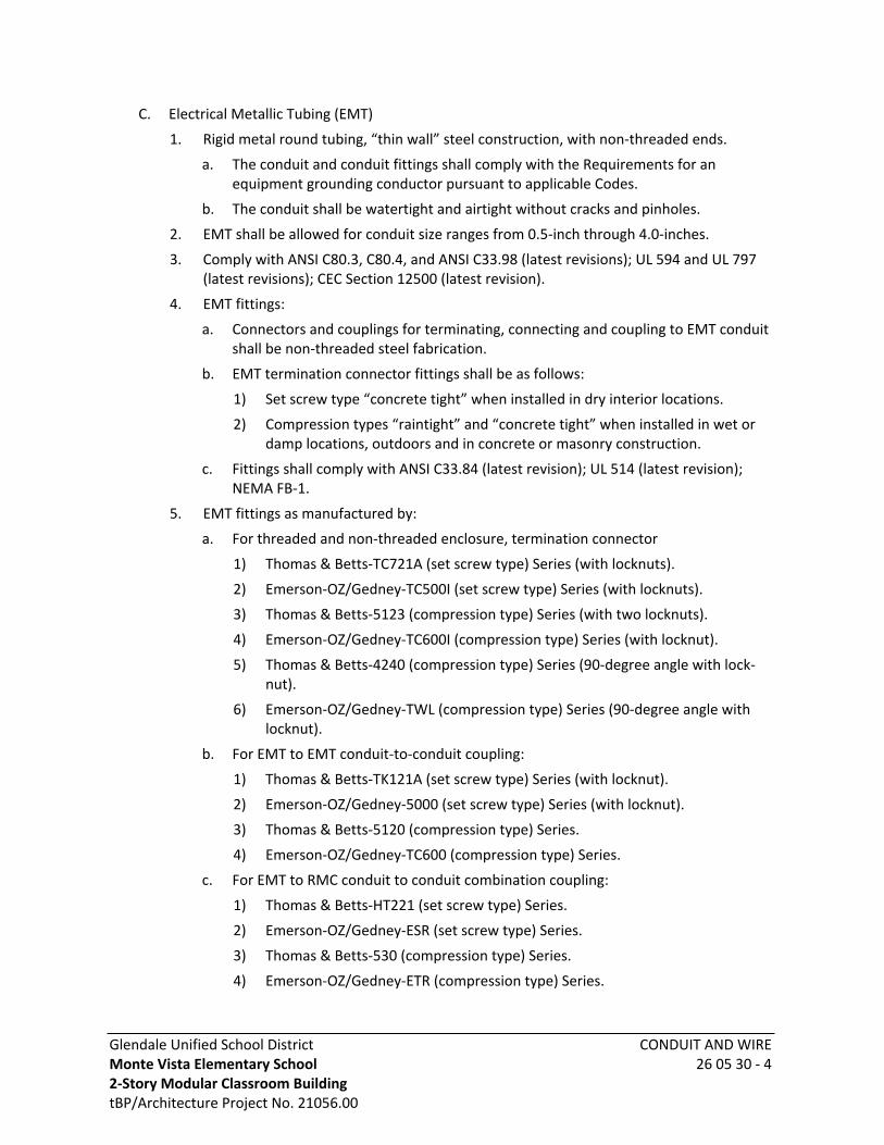
Glendale Unified School DistrictMonte Vista Elementary School 2-Story Modular Classroom BuildingtBP/Architecture Project No. 21056.00
CONDUIT AND WIRE26 05 30 - 4
C. Electrical Metallic Tubing (EMT)
1. Rigid metal round tubing, “thin wall” steel construction, with non-threaded ends.
a. The conduit and conduit fittings shall comply with the Requirements for an equipment grounding conductor pursuant to applicable Codes.
b. The conduit shall be watertight and airtight without cracks and pinholes.
2. EMT shall be allowed for conduit size ranges from 0.5-inch through 4.0-inches.
3. Comply with ANSI C80.3, C80.4, and ANSI C33.98 (latest revisions); UL 594 and UL 797 (latest revisions); CEC Section 12500 (latest revision).
4. EMT fittings:
a. Connectors and couplings for terminating, connecting and coupling to EMT conduit shall be non-threaded steel fabrication.
b. EMT termination connector fittings shall be as follows:
1) Set screw type “concrete tight” when installed in dry interior locations.
2) Compression types “raintight” and “concrete tight” when installed in wet or damp locations, outdoors and in concrete or masonry construction.
c. Fittings shall comply with ANSI C33.84 (latest revision); UL 514 (latest revision); NEMA FB-1.
5. EMT fittings as manufactured by:
a. For threaded and non-threaded enclosure, termination connector
1) Thomas & Betts-TC721A (set screw type) Series (with locknuts).
2) Emerson-OZ/Gedney-TC500I (set screw type) Series (with locknuts).
3) Thomas & Betts-5123 (compression type) Series (with two locknuts).
4) Emerson-OZ/Gedney-TC600I (compression type) Series (with locknut).
5) Thomas & Betts-4240 (compression type) Series (90-degree angle with lock-nut).
6) Emerson-OZ/Gedney-TWL (compression type) Series (90-degree angle with locknut).
b. For EMT to EMT conduit-to-conduit coupling:
1) Thomas & Betts-TK121A (set screw type) Series (with locknut).
2) Emerson-OZ/Gedney-5000 (set screw type) Series (with locknut).
3) Thomas & Betts-5120 (compression type) Series.
4) Emerson-OZ/Gedney-TC600 (compression type) Series.
c. For EMT to RMC conduit to conduit combination coupling:
1) Thomas & Betts-HT221 (set screw type) Series.
2) Emerson-OZ/Gedney-ESR (set screw type) Series.
3) Thomas & Betts-530 (compression type) Series.
4) Emerson-OZ/Gedney-ETR (compression type) Series.

Glendale Unified School DistrictMonte Vista Elementary School 2-Story Modular Classroom BuildingtBP/Architecture Project No. 21056.00
CONDUIT AND WIRE26 05 30 - 5
D. Flexible Metal Conduit (FMC)
1. Round flexible conduit fabricated from a single continuous steel strip. The steel shall be factory formed into continuous interlocking convolutions to form a complete lock between steel strips and provide raceway flexibility.
2. Metal to metal grounding contact shall be maintained throughout the length of the FMC conduit.
3. FMC shall be allowed for conduit size ranges from 0.5 inch through 4.0-inches.
4. FMC shall comply with ANSI-C.33.84 and ANSI C33.92; NEMA FB-1; CEC 12-1100.
5. FMC Fittings
a. FMC fittings shall be malleable iron construction or steel construction.
b. Fitting shall automatically cause the FMC raceway throat opening to be centered with respect to the fitting throat opening.
c. Straight and angled connector termination fittings shall be threaded on one end and shall include a threaded locknut, suitable for connection to threaded and unthreaded enclosures.
d. The attachment of the fittings to FMC shall be angled saddle type, to engage and interlock with the FMC spiral groove, and shall be unaffected by vibration. Direct bearing screw type fittings shall not be used.
e. Direct FMC conduit-to-FMC conduit coupling of FMC shall not be permitted.
f. Shall comply with ANSI C33.9, and ANSI C33.92 (latest revision); NEMA FB1 (latest revision); UL 514.
6. FMC fittings as manufactured by:
a. Straight Termination Connectors 45 and 90 Degree Angle Connectors
1) Thomas & Betts-3110 Series Thomas & Betts-3130 Series(with locknut) (with locknut)
b. FMC to EMT conduit combination coupling:
1) Thomas & Betts 503TB Series.
E. Liquid Tight Flexible Metal Conduit (LTFMC)
1. The metal conduit core of LTFMC shall comply with the same Requirements as FMC conduit, with the addition of a thermoplastic exterior flexible jacket over the metal core.
2. The exterior jacket shall be positively locked to the metal core to prevent jacket “sleeving”.
3. The LTFMC shall be rated for installation and operating service temperatures of between minus 20 degrees centigrade through plus 90 degrees centigrade.
4. The LTFMC jacket shall be suitable for continuous exposure to sunlight, rainwater, water vapor, mineral oils and liquid solvents, without penetrating into the conduit and without deteriorating the jacket.
5. LTFMC sizes from 0.5-inch through 1.25-inch shall include an additional internal ground conductor, fabricated by the Manufacturer, as an integral part of the conduit core.
6. Direct LTFMC conduit-to-LTFMC conduit coupling of LTFMC shall not be permitted.
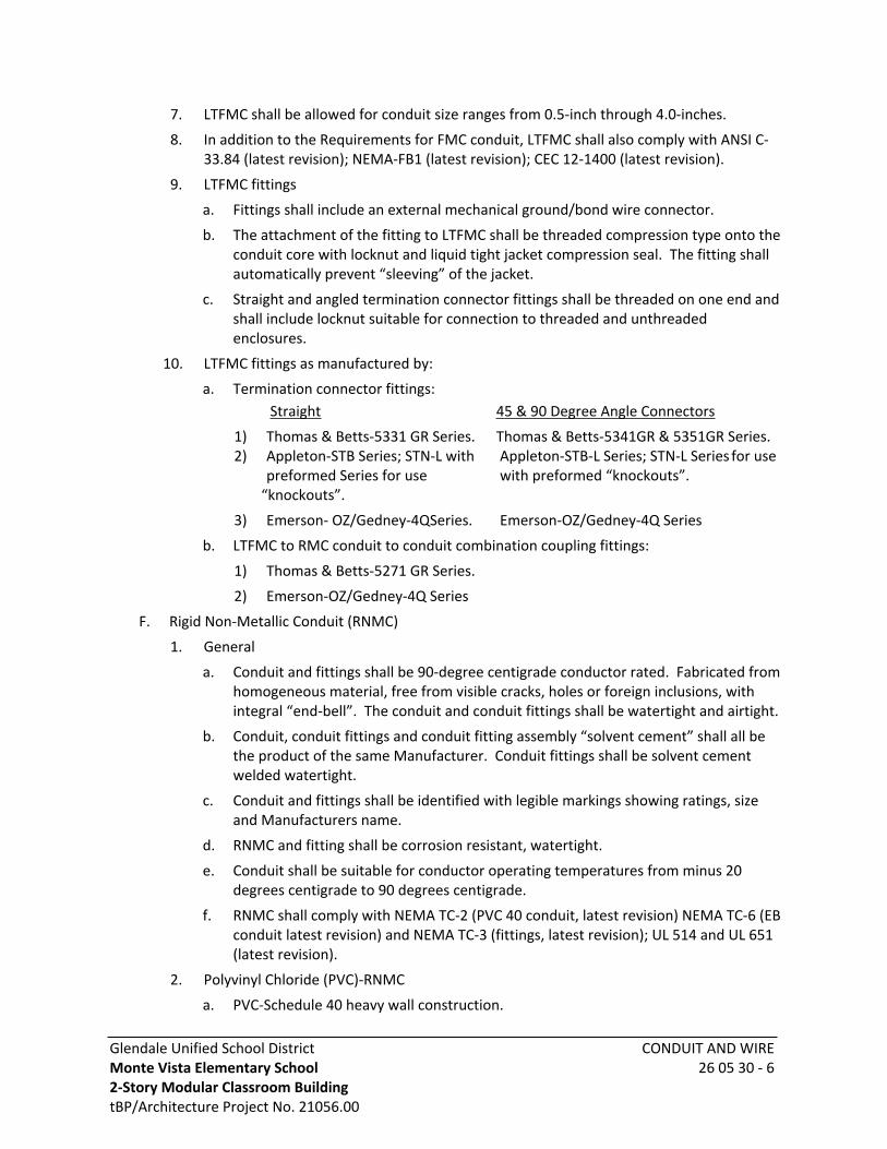
Glendale Unified School DistrictMonte Vista Elementary School 2-Story Modular Classroom BuildingtBP/Architecture Project No. 21056.00
CONDUIT AND WIRE26 05 30 - 6
7. LTFMC shall be allowed for conduit size ranges from 0.5-inch through 4.0-inches.
8. In addition to the Requirements for FMC conduit, LTFMC shall also comply with ANSI C-33.84 (latest revision); NEMA-FB1 (latest revision); CEC 12-1400 (latest revision).
9. LTFMC fittings
a. Fittings shall include an external mechanical ground/bond wire connector.
b. The attachment of the fitting to LTFMC shall be threaded compression type onto the conduit core with locknut and liquid tight jacket compression seal. The fitting shall automatically prevent “sleeving” of the jacket.
c. Straight and angled termination connector fittings shall be threaded on one end and shall include locknut suitable for connection to threaded and unthreaded enclosures.
10. LTFMC fittings as manufactured by:
a. Termination connector fittings: Straight 45 & 90 Degree Angle Connectors
1) Thomas & Betts-5331 GR Series. Thomas & Betts-5341GR & 5351GR Series. 2) Appleton-STB Series; STN-L with Appleton-STB-L Series; STN-L Series for use
preformed Series for use with preformed “knockouts”.“knockouts”.
3) Emerson- OZ/Gedney-4QSeries. Emerson-OZ/Gedney-4Q Series
b. LTFMC to RMC conduit to conduit combination coupling fittings:
1) Thomas & Betts-5271 GR Series.
2) Emerson-OZ/Gedney-4Q Series
F. Rigid Non-Metallic Conduit (RNMC)
1. General
a. Conduit and fittings shall be 90-degree centigrade conductor rated. Fabricated from homogeneous material, free from visible cracks, holes or foreign inclusions, with integral “end-bell”. The conduit and conduit fittings shall be watertight and airtight.
b. Conduit, conduit fittings and conduit fitting assembly “solvent cement” shall all be the product of the same Manufacturer. Conduit fittings shall be solvent cement welded watertight.
c. Conduit and fittings shall be identified with legible markings showing ratings, size and Manufacturers name.
d. RNMC and fitting shall be corrosion resistant, watertight.
e. Conduit shall be suitable for conductor operating temperatures from minus 20 degrees centigrade to 90 degrees centigrade.
f. RNMC shall comply with NEMA TC-2 (PVC 40 conduit, latest revision) NEMA TC-6 (EB conduit latest revision) and NEMA TC-3 (fittings, latest revision); UL 514 and UL 651 (latest revision).
2. Polyvinyl Chloride (PVC)-RNMC
a. PVC-Schedule 40 heavy wall construction.

Glendale Unified School DistrictMonte Vista Elementary School 2-Story Modular Classroom BuildingtBP/Architecture Project No. 21056.00
CONDUIT AND WIRE26 05 30 - 7
b. PVC-Schedule 80 extra heavy wall construction.
c. PVC-Type EB.
3. RNMC fittings connecting to metallic raceways shall be provided with a ground/bond jumper connection.
G. Combi-Duct
1. Rigid nonmetallic conduit combining a continuous linear outer raceway (duct) with factory installed (inside the outer duct) multiple, segregated inner raceway (ducts). Rigid, Schedule 40 PVC construction. Shall be modular lengths of 20-feet for each duct segment.
2. The conduit shall be suitable for use with signal/ telecommunications, fiber optic, tele-phone and computer/data circuits, operating at 100 volts or less, UL listed and labeled.
3. Outer Duct, outer enclosing Schedule-40 PVC duct size. The outer enclosing duct shall be 4.2-inches inside nominal duct diameter and 4.5-inches outer duct nominal diameter.
4. Inner-ducts (Contained inside the enclosing outer duct), non-metallic SDR-19 or Type-C /CAO-8546:
Triple Combi-Duct
a. Quantity of three continuous round rigid inner linear ducts, nominal size inside diameter 1.5-inch for each inner duct.
Quad Combi-Duct
b. Quantity of four continuous round rigid inner linear ducts, nominal size inside diameter 1.19-inch for each inner duct.
5. Manufacturer’s standard bends and offsets, minimum 72-inches radius.
6. Combi-duct and combi-duct fittings shall be airtight and watertight. Approved for direct burial in earth and approved for encasement in concrete.
7. As manufactured by Carlon # Multi-Guard/Multi-Cell Series; American Pipe and Plastic (AMTEL) #Multi-Bore Series; or equal.
H. Expansion Joint, Deflection Joint and Seismic Joint Conduit Fittings
1. Expansion Conduit Fitting - Fitting shall provide for a minimum of 2-inches straight line movement between two connecting conduits in each direction (total 4-inches conduit expansion and contraction) parallel to the respective conduit lengths. Fitting shall be watertight.
2. Deflection Conduit Fitting - Fitting shall provide for a minimum of 30 degrees angular deflection movement (“Shear” deflection) between two connecting conduits, in any direction perpendicular to the length of the respective conduits. Fitting shall be water-tight.
3. Combination Expansion/Deflection Conduit Fitting - Fitting shall provide the combined “expansion” and “deflection” movement capacity between two connecting conduits as described for separate “expansion” and “Deflection” conduit fittings. Fitting shall be approved for installation concealed in both masonry/concrete construction and exposed non-masonry/concrete construction. Fitting shall be watertight.
4. Fittings shall comply with UL.

Glendale Unified School DistrictMonte Vista Elementary School 2-Story Modular Classroom BuildingtBP/Architecture Project No. 21056.00
CONDUIT AND WIRE26 05 30 - 8
5. Fittings as manufactured by:
a. Conduit expansion fittings exposed, or concealed locations as manufactured by:
1) Emerson-OZ/Gedney – AXB-8 Series for RMC conduit.
2) Emerson-OZ/Gedney - TX Series for EMT conduit.
3) Appleton – AXB or XJ8 Series for RMC conduit and EMT conduits. Provide RMC to EMT combination conduit coupling fittings for each end of the expansion fitting.
b. Combination expansion/deflection conduit fittings exposed, or concealed conduit locations as manufactured by:
1) Emerson-OZ/Gedney - AXDX Series for RMC conduit.
2) Emerson-OZ/Gedney - AXDX Series for EMT conduit.
3) Appleton-DX Series for RMC conduit.
4) Provide RMC to EMT combination conduit coupling fittings for each end of the expansion/deflection fitting.
c. Conduit expansion/deflection fittings for FMC and LTFMC conduit.
1) Provide a minimum of 12-inches of “slack” LTFMC in each FMC or LTFMC conduit at building and structure seismic or expansion joint conduit crossings.
2) Note: Each FMC “slack” expansion/deflection location, shall be considered as not less than a 90-degree conduit bend location, for compliance with the maximum quantity of conduit bends allowed in a raceway.
6. Conduit fitting bonding jumper:
a. The grounding/bonding path of metal conduit shall be maintained by the fitting.
b. Provide a bonding jumper at each expansion, deflection and combination expansion deflection conduit fitting.
c. The jumper shall be a bare flexible copper “braid”. The copper braid electrical current carrying capacity shall be equal to the metal conduit.
d. Provide a factory terminated ground clamp on each end of the braid with adjusting steel conduit grounding clamps and connect to each respective conduit end.
e. The jumper braid length shall be 8-inches longer than the respective conduit fitting.
f. Bonding jumper for FMC and EMT fittings as manufactured by:
1) Emerson-OZ/Gedney – BJ and BJE Series
2) Appleton – BJ/XJ Series
I. Conduit Bodies Conduit Fitting
1. Conduit bodies shall provide conductor access with a removable conduit body cover and wiring area enclosed in metal housing. The conduit body shall facilitate pulling conductors.
2. In-line form “C” conduit bodies shall be prohibited.
3. The interior space “length” of 90 degree “elbow” conduit bodies shall not be less than six times the diameter size of the largest conduit connecting to the conduit body.
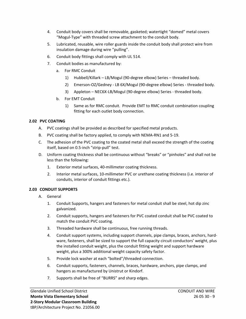
Glendale Unified School DistrictMonte Vista Elementary School 2-Story Modular Classroom BuildingtBP/Architecture Project No. 21056.00
CONDUIT AND WIRE26 05 30 - 9
4. Conduit body covers shall be removable, gasketed; watertight “domed” metal covers “Mogul-Type” with threaded screw attachment to the conduit body.
5. Lubricated, reusable, wire roller guards inside the conduit body shall protect wire from insulation damage during wire “pulling”.
6. Conduit body fittings shall comply with UL 514.
7. Conduit bodies as manufactured by:
a. For RMC Conduit
1) Hubbell/Killark – LB/Mogul (90-degree elbow) Series – threaded body.
2) Emerson-OZ/Gedney - LB 6X/Mogul (90-degree elbow) Series - threaded body.
3) Appleton – NEC6X-LB/Mogul (90-degree elbow) Series - threaded body.
b. For EMT Conduit
1) Same as for RMC conduit. Provide EMT to RMC conduit combination coupling fitting for each outlet body connection.
2.02 PVC COATING
A. PVC coatings shall be provided as described for specified metal products.
B. PVC coating shall be factory applied, to comply with NEMA-RN1 and 5-19.
C. The adhesion of the PVC coating to the coated metal shall exceed the strength of the coating itself, based on 0.5-inch “strip-pull” test.
D. Uniform coating thickness shall be continuous without “breaks” or “pinholes” and shall not be less than the following:
1. Exterior metal surfaces, 40-millimeter coating thickness.
2. Interior metal surfaces, 10-millimeter PVC or urethane coating thickness (i.e. interior of conduits, interior of conduit fittings etc.).
2.03 CONDUIT SUPPORTS
A. General
1. Conduit Supports, hangers and fasteners for metal conduit shall be steel, hot dip zinc galvanized.
2. Conduit supports, hangers and fasteners for PVC coated conduit shall be PVC coated to match the conduit PVC coating.
3. Threaded hardware shall be continuous, free running threads.
4. Conduit support systems, including support channels, pipe clamps, braces, anchors, hard-ware, fasteners, shall be sized to support the full capacity circuit conductors’ weight, plus the installed conduit weight, plus the conduit fitting weight and support hardware weight, plus a 300% additional weight capacity safety factor.
5. Provide lock washer at each “bolted”/threaded connection.
6. Conduit supports, fasteners, channels, braces, hardware, anchors, pipe clamps, and hangers as manufactured by Unistrut or Kindorf.
7. Supports shall be free of “BURRS” and sharp edges.

Glendale Unified School DistrictMonte Vista Elementary School 2-Story Modular Classroom BuildingtBP/Architecture Project No. 21056.00
CONDUIT AND WIRE26 05 30 - 10
8. Metal supports cut in the field shall be zinc galvanized after cutting to prevent rust.
B. Conduit Hangers
1. Threaded steel hanger rods.
a. Hanger rods smaller than 0.375-inches in diameter shall not be used for support of individual conduits.
b. Hanger rods smaller than 0.5-inches in diameter shall not be used for support of multiple conduits.
2. Conduit hanger wires shall be not less than 12-gauge steel.
3. Conduit hangers shall attach to structure fasteners with steel “Clevis” or “Swing” hangers and shall provide a minimum of 45 degrees of angular movement in any direction at the point of the conduit hanger attachment to the structure fasteners.
4. Conduits individually suspended by conduit hangers shall fasten to the respective hangers with “Clevis” type pipe hangers. The pipe hangers shall be steel, adjustable to fit conduit size and shall completely enclose the conduit circumference.
C. Conduit Support Channels
1. “C” channels shall be factory preformed with a minimum 12-gauge thickness metal. The channel shall be factory “punched” with regularly spaced slotted holes for fastener attachments along the length of the channel.
2. The “C” channel shall not deflect more than 0.1 inch between channel supports at maximum installed design load, including required safety factor.
3. Channels shall comply with ANSI-1008 (latest revision) and ASTM-A569 latest revision).
4. Channels shall provide “turned lips” at longitudinal edges to hold (lock-in) fasteners.
5. Conduit support channels suspended from conduit hangers shall attach to conduit hangers with treaded connections. Provide a minimum of two hangers (trapeze style) connected to each channel.
6. Non-suspended conduit support channels shall connect to structure fasteners with threaded connectors.
D. Fasteners, Seismic Earthquake Rated
1. Channel fasteners:
a. Channel fasteners shall “prelocate” and lock into the channel “turned lips” and channel “walls”.
b. A separate metal strap shall “tie” each conduit to each channel with conduit channel fasteners.
2. Structure fasteners:
a. Structure fasteners for wall and floor mounted conduit attachments shall attach to existing masonry and concrete structures with structure fasteners using drilled, mechanical, expansion shield anchors.
b. Structure fasteners for wall and floor mounted conduit attachments shall attach to new masonry and concrete structures with structure fasteners using steel threaded inserts precast into the structures.
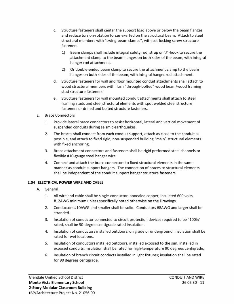
Glendale Unified School DistrictMonte Vista Elementary School 2-Story Modular Classroom BuildingtBP/Architecture Project No. 21056.00
CONDUIT AND WIRE26 05 30 - 11
c. Structure fasteners shall center the support load above or below the beam flanges and reduce torsion-rotation forces exerted on the structural beam. Attach to steel structural members with “swing-beam clamps”, with set-locking screw structure fasteners.
1) Beam clamps shall include integral safety rod, strap or “J”-hook to secure the attachment clamp to the beam flanges on both sides of the beam, with integral hanger rod attachment.
2) Or double-ended beam clamp to secure the attachment clamp to the beam flanges on both sides of the beam, with integral hanger rod attachment.
d. Structure fasteners for wall and floor mounted conduit attachments shall attach to wood structural members with flush “through-bolted” wood beam/wood framing stud structure fasteners.
e. Structure fasteners for wall mounted conduit attachments shall attach to steel framing studs and steel structural elements with spot welded steel structure fasteners or drilled and bolted structure fasteners.
E. Brace Connectors
1. Provide lateral brace connectors to resist horizontal, lateral and vertical movement of suspended conduits during seismic earthquakes.
2. The braces shall connect from each conduit support, attach as close to the conduit as possible, and attach to fixed rigid, non-suspended building “main” structural elements with fixed anchoring.
3. Brace attachment connectors and fasteners shall be rigid preformed steel channels or flexible #10-gauge steel hanger wire.
4. Connect and attach the brace connectors to fixed structural elements in the same manner as conduit support hangers. The connection of braces to structural elements shall be independent of the conduit support hanger structure fasteners.
2.04 ELECTRICAL POWER WIRE AND CABLE
A. General
1. All wire and cable shall be single-conductor, annealed copper, insulated 600 volts, #12AWG minimum unless specifically noted otherwise on the Drawings.
2. Conductors #10AWG and smaller shall be solid. Conductors #8AWG and larger shall be stranded.
3. Insulation of conductor connected to circuit protection devices required to be "100%" rated, shall be 90-degree centigrade rated insulation.
4. Insulation of conductors installed outdoors, on grade or underground, insulation shall be rated for wet locations.
5. Insulation of conductors installed outdoors, installed exposed to the sun, installed in exposed conduits, insulation shall be rated for high-temperature 90 degrees centigrade.
6. Insulation of branch circuit conducts installed in light fixtures; insulation shall be rated for 90 degrees centigrade.

Glendale Unified School DistrictMonte Vista Elementary School 2-Story Modular Classroom BuildingtBP/Architecture Project No. 21056.00
CONDUIT AND WIRE26 05 30 - 12
7. Conductor exposed to oil, insulation and jacket shall be oil resistant, complying with “Oil Resistant-1” and “Oil Resistant-2” UL 83.
B. Conductor Insulation
1. 600 Volt AC and/or DC insulated conductors installed entirely inside conduits, or enclosed inside wireways, or enclosed inside raceways, insulation shall be rated as follows.
2. Indoor above Grade locations either concealed or exposed.
a. Dual rated THHN and THWN
b. Individually rated THHN-2
c. Individually rated THWN-2
d. XHHW-2
3. Outdoor above Grade either concealed or exposed.
a. XHHW-2
b. THWN-2
c. THW-2
4. Outdoor below Grade or outdoor on Grade.
a. XHHW-2
b. THWN-2
c. THW-2
5. All other enclosed raceway locations not described above.
a. XHHW-2
b. THWN-2
c. THW-2
6. Health Care facilities all circuits insulation shall be XHHW-2, rated Hospital-Grade.
7. 600 Volt AC and/or DC insulated conductors installed in open cable tray or open wireway or exposed insulation also shall be rated for exposed install locations.
C. InsulationColor Coding and Identification
1. The following color code for branch circuits:
a. Neutral . . . White (Tape feeder neutrals with white tape near connections)
b. Normal Power:120/208 VoltGround GreenPhase A BlackPhase B RedPhase C Blue
c. Isolated ground insulation shall be green with a longitudinal yellow stripe.

Glendale Unified School DistrictMonte Vista Elementary School 2-Story Modular Classroom BuildingtBP/Architecture Project No. 21056.00
CONDUIT AND WIRE26 05 30 - 13
d. Emergency power same insulation color as normal power except as follows:120/208 VoltProvide a continuous stripe on each conductor insulation, orange or yellow, except ground.
2. When individual neutral conductors are shown for each branch circuit, the color code for the neutral conductors shall be as follows:
a. 120/208 volt; Phase A - White with Black stripe; Phase B - White with Red stripe; Phase C - White with Blue stripe.
3. Feeders identified as to phase or leg in each, switchboard, switchgear, panelboard, and junction location with printed identifying tape.
4. Fire alarm conductors: Use 600-volt, type THHN-2/THWN-2 conductors and color-coded per Equipment Manufacturer's recommendations and approved and listed for use on fire alarm systems by the State Fire Marshal.
5. Color coding for mechanical and plumbing control wiring shall be an agreed upon color code between the Mechanical/Plumbing Contractor and the Electrical Contractor, and color code shall be submitted to the District’s Representative in writing for approval prior to installation.
D. Panel feeders, copper or aluminum:
1. Wire size shown on the Drawings is for copper conductors, unless specifically indicated otherwise.
2.05 CABLE RACKS
A. Cable racks, installed on the vertical walls of the structure, including hooks and porcelain insulator cable cradles, shall be sufficient to accommodate the cables and splices.
B. Vertical racks shall be installed on all walls of the structure a minimum of 24-inches on center within 6-inches of floor and top of wall. A rack shall be installed within 18-inches of each corner of each wall. Additional racks spaced equally on each wall shall be installed; spacing between vertical wall racks shall not exceed 24-inches.
1. Wall racks shall be slotted to accept removable hooks and lock hooks into place.
2. Non-metallic, 50% (minimum) glass reinforced nylon or non-metallic material of the same characteristics.
3. The installed cable racks, cable support hooks with arms and wall anchor bolts shall support the following minimum loads for each hook/arm, with a 200% minimum safety factor. Based on multiple hook/arms located not less than 9-inches on center along the entire vertical length of the support rack:
Min. Weight Each Max. Allowable Hook/Arm Length Hook/Arm Supported Hook/Arm Deflectiona. 8-inches 450 pounds 0.25-inchb. 14-inches 350 pounds 0.37-inchc. 20-inches 250 pounds 0.37-inch
(Based on load concentrated 1-inch from the end of each hook/arm.)

Glendale Unified School DistrictMonte Vista Elementary School 2-Story Modular Classroom BuildingtBP/Architecture Project No. 21056.00
CONDUIT AND WIRE26 05 30 - 14
4. Racks shall be bolted to the precast and cast-in place structure walls, within 3-inches of each rack end and not less than 9-inches on center. Provide cast-in place or after-set drilled expansion concrete anchors.
PART 3 - EXECUTION
3.01 TRENCHING, FOOTINGS, SLEEVES
A. Provide trenching, concrete encasement of conduits, backfilling, and compaction for the underground electrical work, in accordance with applicable Sections of this Specification.
B. Provide footings for all post and/or pole-mounted lighting fixtures: concrete shall conform to the applicable Sections of this Specification.
C. Sleeves
1. Provide sleeves for raceways, conduit and wire/cables passing through the following construction elements:
a. Concrete and masonry foundations, floors, walls and slabs.
b. Gypsum, Lath, and plaster walls and ceilings.
c. Building structures (i.e., foundations, walls, floors, ceilings, beams, and roofs) with a fire rating exceeding 20-minutes.
2. Sleeves shall extend 1.5-inch above and below floors, except under floor standing electrical equipment. Sleeves shall be flush with wall ceiling foundations and partitions exposed to public view and extend approximately 0.5-inch past penetration in fire rated construction. Sleeves shall be installed at exact penetration locations and angles to accommodate wire/cable, raceway and conduit routings.
3. Joists, girders, beams, columns or reinforcing steel shall not be cut or weakened. Where construction necessitates the routing of conduit or raceways through structural members, framing or footings, written permission to make such installation shall first be obtained from the District’s Representative. Such permission will not be granted, how-ever, if any other method of installation is possible.
4. The layout and design of raceways and conduits located in or routed through masonry or reinforced beams or the District’s Representative shall review walls before any work is performed. All sleeving shall be accomplished according to the instructions of the District’s Representative and shall be accepted before any concrete is poured.
5. Sleeves, raceways and conduit shall be located to clear steel reinforcing bars in beams. Reinforcing bars in walls shall be offset to clear piping and sleeves.
6. Provide a continuous clearance between the inside of a sleeve and exterior of wire/ cables, conduits and raceways passing through the sleeve not less than the following:
a. 0.5-inch clearance except as required otherwise.
b. 1.0-inch clearance through outside walls below grade.
c. 3.0-inch clearance through seismic joints.
7. Sleeves set in fire rated construction shall be caulked between sleeve and building structure, additionally sleeves shall be caulked between the sleeve and the wire/cables, conduits/raceways passing through the sleeve. The caulking shall be a fireproof sealant,
Glendale Unified School DistrictMonte Vista Elementary School 2-Story Modular Classroom BuildingtBP/Architecture Project No. 21056.00
CONDUIT AND WIRE26 05 30 - 15
equal to the fire rating and temperature being penetrated. Clearance between components inside of sleeve and exterior of components passing through sleeve and between components inside the sleeve shall comply with Fireproof Sealant Manufacturer’s recommendations.
8. Sleeve material:
a. In floor construction: Schedule 40 black steel pipe, with upper surface to be sealed watertight.
b. In concrete or masonry walls roofs or ceilings: Schedule 40 black steel pipe. When installed in roofs or outside walls, seal outer surface watertight.
c. In fire rated construction; 24-gauge galvanized iron or steel.
d. Sleeves through waterproof membranes: Cast iron or Schedule 40 steel with flashing clamp device and corrosion resistant clamping bolts. Caulk space between pipe and sleeve and surfaces between sleeve and conduits sealed watertight.
3.02 GROUNDING
A. Grounding shall be executed in accordance with all applicable Codes and Regulations, both of the State and local authorities having jurisdiction.
B. Where nonmetallic conduit is used in the distribution system, the Contractor shall install the proper sized copper ground wire in the conduit with the feeder for use as an equipment ground. The electrical metallic raceway system shall be grounded to this ground wire.
C. The maximum ground/bond resistance to the grounding electrode shall not exceed 1ohms from any location in the electrical system. The maximum ground resistance of the grounding electrode to earth shall not exceed 5 ohms.
D. Ground/Bond Conductors
1. Provide an additional, dedicated, green insulation equipment ground/bond wire inside each conduit type and raceway as follows. Size the ground/bond conductors to comply with CEC/NEC Requirements. The metal conduit or raceway shall not be permitted to serve (function) as the only (exclusive) electrical ground return path:
a. All types of nonmetallic conduit and all types of non-metallic raceways including but not limited to: RNMC - Rigid Nonmetallic Conduit.
b. FMC – Flexible Metal Conduit.
c. LTFMC – Liquid Tight Flexible Metal Conduit.
d. Metal and non-metal raceways.
e. RMC – Rigid Metal Conduit.
f. EMT – Electrical Metal Tubing.
2. The equipment ground/bond wire shall be continuous from the electrical circuit source point of origin to the electrical circuit end termination utilization point as follows:
a. Every conduit and raceway path containing any length of the above identified conduits or raceway.
b. Every conduit path and raceway path connected to any length of the above-identified conduits and raceways.
Glendale Unified School DistrictMonte Vista Elementary School 2-Story Modular Classroom BuildingtBP/Architecture Project No. 21056.00
CONDUIT AND WIRE26 05 30 - 16
3. The equipment ground/bond wire shall be sized as follows, but in no case smaller than indicated on the Drawings. Install equipment ground/bond wire in each conduit/race-way, with the respective phase conductors:
Feeder, Subfeeders & Branch Circuit Protection Min. Equip Ground Wire Size 15 amp #12
20 amp #12 30 to 60 amp #10 70 to 100 amp #8 101 to 200 amp #6 201 to 400 amp #2 401 to 600 amp #1 801 to 1000 amp 2/01001 to 1200 amp 3/01201 to 1600 amp 4/01601 to 2000 amp 250 MCM2001 to 2500 amp 350 MCM2501 to 4000 amp 500 MCM
4. Isolated grounds - Raceways containing branch circuit or feeder phase conductors connected to panelboards equipment, or receptacles with isolated grounds or isolated ground bus shall contain a dedicated insulated ground conductor connected to the isolated ground system only. The isolated ground conductor shall be continuous the length of the raceways and connected only to the isolated ground terminals in addition to and independent of the equipment bonding/ground conductor. The isolated ground conductor shall be sized as indicated above, for equipment ground/bond wire.
5. Splices in ground/bond wires shall be permitted only at the following locations:
a. Ground buses with listed and approved ground lugs.
b. Where exothermic welded ground/bond wire splices are provided.
6. Provide ground/bond wire jumpers for conduit fittings with ground lugs, expansion and deflection conduit fittings at conduit fittings connecting between metallic and non-metallic raceways and to bond metal enclosures to conduit fittings with ground lugs.
E. Where conductors are run in parallel in multiple raceways, the grounding conductor shall be run in parallel. Each parallel equipment-grounding conductor shall be sized on the basis of the ampere rating of the overcurrent device protecting the circuit conductors in the raceway. When conductors are adjusted in size to compensate for voltage drop, grounding conductors, where required, shall be adjusted proportionately in size.
F. Ground conductors for branch circuit wiring shall be attached at each outlet to the back of the box using drilled and tapped holes and washer head screws, 6-32 or larger.
G. Each panelboard, switchboard, pull box or any other enclosure in which several ground wires are terminated shall be equipped with a ground bus secured to the interior of the enclosure. The bus shall have a separate lug for each ground conductor. No more than one conductor shall be installed per lug.
Glendale Unified School DistrictMonte Vista Elementary School 2-Story Modular Classroom BuildingtBP/Architecture Project No. 21056.00
CONDUIT AND WIRE26 05 30 - 17
3.03 CONDUIT
A. General
1. The sizes of the conduits for the various circuits shall be as indicated on the Drawings, but not less than the conduit size required by Code for the size and quantity of conductors to be installed in the conduit.
2. Conduits shall be installed concealed from view. Install conduits concealed in walls, concealed below floors and concealed above ceilings, except as specifically noted otherwise.
a. Conduits shall not be installed in concrete floors.
3. The following systems shall be considered as circuits 100 volts and less, all other circuits shall be considered to be over 100-volts (power circuits) unless specifically noted other-wise: Fire alarm, energy management control, telephone, public address, data, computer, television, intercom, intrusion alarm and nurse call.
4. Conduits shall be provided complete with conduit bends, conduit fittings, outlet boxes, pullboxes, junction boxes, conduit anchors/supports, grounding/bonding for a complete and operating conductor/wire raceway system.
5. Metal and nonmetal conduits shall be provided mechanically continuous between termination connection points. Metal conduit shall be provided electrically continuous between termination connection points.
6. Individual conduit paths and home runs shown on the Drawings shall be maintained as separate individual conduits for each homerun and path.
7. Conduits, conduit fittings and installation work occurring in classified hazardous materials locations shall comply with applicable Code Class 1 Division 1 Requirements, unless specifically noted otherwise.
8. Transitions between conduits constructed of different materials and occurring in above grade locations shall be allowed only at outlet boxes, junction boxes, pull boxes and equipment enclosures unless specifically indicated otherwise. Provide outlet boxes and junction boxes.
9. Metal conduit terminating to nonmetal enclosures; terminating into metal enclosures with “concentric.ring” knockouts; terminating into metal enclosures with knockout reducing washers, including but not limited to equipment housings, outlet boxes, junction boxes, pull boxes, cable trenches, manholes, shall be provided with a ground/ bonding lug integrated with the conduit termination conductor fitting construction, by the Fitting Manufacturer. The lug shall provide for connection of a grounding/bonding conductor (insulated or uninsulated). The grounding lug shall be located on the fitting, inside the termination enclosure.
10. The type of conduit, type of conduit fittings, and type of conduit supports, and method of conduit installation shall be suitable for the conditions of use and conditions of location of installation based on the Manufacturer’s recommendations; based on the applicable Codes and based on the Requirements of the Contract Documents.

Glendale Unified School DistrictMonte Vista Elementary School 2-Story Modular Classroom BuildingtBP/Architecture Project No. 21056.00
CONDUIT AND WIRE26 05 30 - 18
B. RMC Installation Locations
RGS, IMC conduits and RGS, IMC fittings shall be installed in the following locations:
1. Embedded in floors, walls, ceilings, roofs, foundations, and footings constructed with concrete.
2. Embedded in walls and foundations constructed with brick and masonry.
3. Interior of buildings, within 9-feet of finish floor lines for exposed conduit locations.
4. Exterior of building for exposed conduit locations.
5. Damp or wet locations exposed or concealed locations.
6. Exposed on roofs.
7. In hazardous materials areas and locations; below hazardous materials areas and locations; above hazardous materials areas and locations.
8. Exposed on utility service poles, for pole risers less than 9-feet above finish grade.
9. RMC conduit and RMC fittings may be installed in any location where EMT and FMC conduit is permitted to be installed.
C. PVC Coated RMC Installation Locations
PVC coated RMC conduit and PVC coated RMC fittings shall be installed in the following locations:
1. Underground conduit locations for elbows and bends with a radius of less than 36-times the conduit diameter.
2. Underground vertical risers extending above grade.
3. Entire length of underground conduits for the following circuits:
a. Audio microphones
b. Lighting dimming controls
4. Installed in contact with earth or corrosive materials.
5. Exposed in “cold” rooms and “refrigerated” rooms, rooms with a maintained temperature below 65 degrees Fahrenheit.
D. EMT Installation Locations
EMT conduit and EMT fittings may be installed in the following locations, for circuit conductors operating below 600 volts to ground; locations containing only “non-hazardous materials”; only dry locations:
1. Concealed in hollow non masonry/non-concrete, metal stud frame and wood stud frame walls and floors.
2. Concealed above ceilings.
3. Exposed inside interior enclosed crawl spaces.
4. Exposed interior locations placed 9-feet or higher above finished floors (except as described in paragraph below at lower heights).
5. Exposed on walls and ceilings (any height) in the following dedicated function areas, interior enclosed room locations:
a. Indoor enclosed electrical equipment rooms and closets.

Glendale Unified School DistrictMonte Vista Elementary School 2-Story Modular Classroom BuildingtBP/Architecture Project No. 21056.00
CONDUIT AND WIRE26 05 30 - 19
b. Indoor enclosed data and telecommunication terminal rooms and closets.
c. Indoor enclosed HVAC equipment rooms and closets.
6. Any location where FMC is described to be installed, except as the final connection to rotating or vibrating equipment.
E. FMC Installation Locations
FMC conduit and FMC fittings may be installed in the following locations for circuit conductors operating below 600 volts to ground; locations containing only “non-hazardous materials”; only dry, interior locations:
1. Concealed in hollow non-masonry metal stud frame and wood stud frame fully enclosed walls.
2. Concealed above fully enclosed ceiling spaces.
3. FMC conduit shall be installed in continuous lengths between termination points. FMC shall not be “spliced” or coupled directly to FMC or any other conduit type under any circumstance.
4. The maximum continuous length of FMC that shall be installed between termination end points is 15-feet. Circuits requiring continuous conduit lengths exceeding 15 feet between termination end points shall be installed using either RMC or EMT conduits. FMC lengths shorter than 16-inches are prohibited.
5. The minimum size FMC conduit shall be as shown on the Drawings but not be less than the following:
a. FMC lengths of 6-feet or less, minimum FMC conduit size shall be 0.50-inch.
b. FMC lengths exceeding 6-feet, minimum FMC conduit size shall be 1.0-inch.
F. LTFMC Installation Locations
LTFMC conduit and LTFMC fittings shall be installed in the following locations for circuit conductors operating below 600 volts to ground; locations containing only “non-hazardous materials”:
1. Final electrical connection to vibrating or rotating equipment; control and monitoring devices mounted on vibrating and rotating equipment including the following. Minimum conduit length shall not be less than 24-inches:
a. Motor, engines, boilers, solenoids, and valves.
b. Fixed mounted “shop” (manufacturing) production equipment.
c. Fixed mounted food preparation equipment and “kitchen” equipment.
2. All locations where exposed flexible conduit connections are required, both indoor and outdoor.
3. Final connection to indoors electrical transformers. Minimum conduit length shall not be less than 24-inches; maximum conduit length shall not exceed 72-inches.
4. Do not install LTFMC located in environmental air plenums.
Glendale Unified School DistrictMonte Vista Elementary School 2-Story Modular Classroom BuildingtBP/Architecture Project No. 21056.00
CONDUIT AND WIRE26 05 30 - 20
G. RNMC Installation Locations
RNMC conduit and RNMC fittings shall be installed in the following locations containing only “non-hazardous material”:
1. Underground, concealed below earth grade, unless specifically noted or specified other-wise.
2. Exposed on utility service poles, for pole risers at 9-feet or higher above finish grade, Schedule 80 PVC only.
3. RNMC Type “EB” conduit(s) shall be concrete encased along the entire length of the conduits for all installation locations.
4. Non-metal type raceways and RNMC type conduit shall not be installed inside buildings.
H. Combi-Duct Installation Locations
Combi-duct conduits shall be installed where shown on the Drawings. Combi-duct shall be installed underground (below grade) as follows:
1. Do not install exposed or inside buildings above grade.
2. Provide a 0.25-inch pull rope in each inner duct.
3. Radius and elbows shall be rigid non-metallic, PVC, Manufacturer factory fabricated, in lieu of PVC coated RMC conduit.
4. Inner ducts shall be supported by internal spacers inside the enclosing outer duct.
5. Provide end bell and three hole "snug-plugs" at each entrance end of Combi-duct into pullboxes, manholes, equipment cabinets stub-ups and Combi-duct terminations. Com-pression type “snug-plugs” shall provide watertight and airtight seal between inner and outer ducts and around future cables installed in inner duct.
I. Conduit Installation
1. Conduit Supports
a. Securely and rigidly support all raceways/conduits from the building structure. Race- ways/Conduits shall be supported independent of all piping, air ducts, equipment ceiling hanger wires, and suspended ceiling grid systems. Secure conduit to structural element by means of UL listed and approved hangers, fasteners, “C” channels and pipe clamps.
b. Provide conduit supports spaced along the length of the conduit as follows:
1) RMC and EMT conduit, maximum not to exceed 96-inches on center; within 24-inches of each conduit bend and conduit termination location.
2) FMC and LTFMC conduit, maximum not to exceed 24-inches on center; within 6-inches of each conduit bend and conduit termination location.
c. Suspended conduit methods:
1) Individual, suspended raceways/conduits separated by more than 12-inches from any other conduit and suspended from ceilings and roofs shall be supported as follows:a) Conduits smaller than 1.5-inches by means of hanger rods or hanger wires. b) Conduits 1.5-inches and larger by means of hanger rods.
Glendale Unified School DistrictMonte Vista Elementary School 2-Story Modular Classroom BuildingtBP/Architecture Project No. 21056.00
CONDUIT AND WIRE26 05 30 - 21
c) The conduit shall attach to the hangers with pipe clamps.
2) Suspended raceways/conduits positioned within 24 inches of any other conduit shall be grouped and supported by hanger rods using trapeze type conduit support channels ("C" channels). Conduits shall individually attach to common channels side-by-side, with pipe clamps.
d. Non-suspended conduit methods:
1) Individual raceway/conduits placed against wall/ceiling/floors, placed inside hollow wall/ceiling construction or structure framing (i.e., “dry- wall” or plaster hollow wall construction), shall be secured by means of individual pipe clamps and fasteners attached to the framing studs or other structural members and the conduit/raceway.
2) Provide common “C" channel supports for all multiple raceway/conduits placed against vertical or horizontal surfaces and positioned within 24-inches of other raceways/conduits. Attach channels to the framing studs or other structural members. Attach the conduits/raceway individually to common channels, side-by-side, with pipe clamps.
3) The use of toggle bolts is prohibited.
e. Conduit rising from floor for motor connection shall be independently supported if extending over 18-inch above floor. Support shall not be to a motor or ductwork, which may transmit vibrations.
f. Provide conduit anchoring, conduit support and conduit bracing systems conforming to Earthquake Seismic Zone 4 Requirements. The conduit support/anchoring system capacity shall include the weight of the conduits, conduit fittings, conduit supports, and conductors/wires/cables installed in the conduits plus a 300% safety factor. Submit Shop Drawing details showing each typical conduit anchor, conduit support and conduit brace location. Submit structural calculations performed by and signed by a Professional Structural Engineer (P.E.) with a P.E. license, registered in the State of California, U.S.A.
2. Conduit separation:
a. Conduit installed underground or below building slab without full concrete encasement: Shall be separated from adjacent conduits of identical systems (i.e., signal to signal, data to data, power to power, control to control etc.) by a minimum of 3-inches. Conduits of non-identical systems (i.e., signal to power; data to power; power to control; signal to control, etc.) shall be separated by a minimum of 12-inches.
b. Conduit installed underground with full concrete encasement; shall be separated from adjacent conduits of similar systems (100 volt and less) by a minimum of 2-inches; conduits for non-power systems (100 volts and less to ground) shall be separated by a minimum of 6-inches from power circuits (over 100 volts to ground); conduits for power circuits shall be separated from adjacent conduits of similar power systems (over 100 volts to ground) by a minimum of 3-inches.
c. Separation of conduits entering termination points or crossing other conduits may be reduced as required within 60-inches of the termination or crossing points.
Glendale Unified School DistrictMonte Vista Elementary School 2-Story Modular Classroom BuildingtBP/Architecture Project No. 21056.00
CONDUIT AND WIRE26 05 30 - 22
d. Conduits containing Utility Company service circuits (i.e., electrical power, tele-phone, or cable television) shall be separated a minimum of 12-inches from all other utilities and conduits, with or without concrete encasement, metallic or non-metallic conduit, above grade or underground conduit locations.
e. Conduits shall be separated from hot water piping, exhaust flues/chimneys, steam piping, boilers, furnaces, ovens by a minimum of 12-inches.
3. Conduit stubs:
a. Branch circuit and telephone conduits turned up from floor at the following locations shall terminate each conduit in a flush conduit coupling at the floor and then extend into partition or to equipment. Refer to District’s Representative’s Drawings for location of walls and partitions.
1) Interior demountable partitions.
2) Below, into or adjacent to equipment not installed directly adjoining to a wall.
3) Up from below the floor into hollow stud frame walls.
b. From each panel, and signal cabinet which is wall mounted, stub up from top of the panel/cabinet a minimum of three 1-inch conduits to the nearest accessible ceiling spaces or other accessible location. Where the floor below the panel is accessible or is a ceiling space, stub an additional three 1-inch conduits from the bottom of the panel into the accessible space below the panel. Cap conduits for future use.
c. Conduits stubbed underground outside of building line for future use shall be terminated a minimum of five feet clear (whichever distance is greater) of building or adjacent concrete walks and AC paving. The stubout conduit shall be capped. Provide concrete monuments, 6-inches by 6-inches by 15-inches deep, buried flush with grade over the capped ends. The face of monument shall be furnished with 3-inch square brass plates securely mounted and engraved with the number and size of conduits and type of service (i.e., "POWER", "TEL.", etc.).
d. Conduits stubbed into ceiling or floor spaces from outlets for telephone, video, computer/data or television shall be provided with an insulated throat bushing, on the end of each conduit stubout.
e. Conduit stub-outs from outlet boxes and equipment located in hollow stud walls, into ceiling and floor spaces, shall be EMT or RMC conduit. The stub-outs shall terminate into the ceiling and floor spaces with a conduit termination connector fitting.
f. Empty conduit stubs into building spaces and equipment shall be individually identified with an “ID-tag” located at each end of the conduit. The ID-tag shall state the origination point and termination point of the respective conduit (i.e., “from PNL-A/to Room #121”; “from outlet #24/to outlet #17 in Room #120”; etc.).
g. Provide a conduit termination fitting with insulated throat bushing and mechanical ground lugs at each conduit “stub-up” location.

Glendale Unified School DistrictMonte Vista Elementary School 2-Story Modular Classroom BuildingtBP/Architecture Project No. 21056.00
CONDUIT AND WIRE26 05 30 - 23
4. Conduit concrete encasement:
a. Conduits which are run underground exterior to building slab shall be continuously concrete encased except, 15-amp and 20-amp power branch circuit conduits under-ground do not require concrete encasement.
b. PVC rigid-non-metallic-type EB conduit, of any size and any location shall be continuously concrete encased the full length of the conduit installation, including under building slab.
c. Concrete for encasement of underground conduits shall be 2000-PSI 28-days cure strength with a mix of cement, sand, water and maximum of ¾-inch gravel. Concrete encasement of conduits shall be continuous without voids. The encasement shall extend 3-inches past the edges of all conduits on all sides of the circuit. Provide ten pounds of red oxide cement coloring uniformly mixed with each cubic yard of concrete for conduit encasement.
d. Conduits located below or adjacent to structural foundations shall be separated from the foundation by a minimum of 12-inches. Conduits located below structural foundations shall be fully and continuously concrete backfilled and encased between the bottom of the foundation to the bottom of the conduits. The concrete shall be 4000 PSI 28-day cure strength instead of 2000-PSI concrete.
e. Conduits of any size and type (including 15 amp and 20-amp power branch circuits) located under roads, paved areas and “transit-system” right of way shall be concrete encased.
5. Underground conduits:
a. Three or more underground conduits larger than 1-inch in size and occupying the same trench shall be separated and supported on factory fabricated, non-metallic, duct/conduit support spacers. The spacers shall be modular, keyed interlocking type, "built-up" to accommodate quantity, size orientation and spacing of installed conduits. The spacers shall maintain a constant distance between adjacent conduit supports and hold conduits in place during trench backfill operations. Minimum support spacer installation interval along with length of the conduits shall be as follows:
1) Concrete encased conduits, not less than 8-feet on center.
2) Non-concrete encased conduits, not less than 5-feet on center.
b. Provide trenching, excavation, shoring and Backfilling required for the proper installation of underground conduits. Tops of backfill shall match finish grade.
c. Bottoms of trenches shall be cut parallel to “finish grade” elevation. Make trenches 12-inches wider than the greatest diameter of the conduit.
d. Back-filling Trenches for Conduits without Concrete Encasement Requirements
1) Conduits which are not required by the Contract Documents to be concrete encased and are located exterior to building slab, shall be set on a 3-inch bed of damp clean sand. Conduit trenches shall be backfilled to within 12-inches of finished grade with damp sand after installation of conduit is completed. Remainder of backfill shall be native soil.

Glendale Unified School DistrictMonte Vista Elementary School 2-Story Modular Classroom BuildingtBP/Architecture Project No. 21056.00
CONDUIT AND WIRE26 05 30 - 24
2) Conduits located under a building which are not required by the Contract Documents to be concrete encased, shall be completely backfilled and comp-acted with clean damp sand to the same level as the building foundation pad.
3) Provide a continuous yellow 12-inches wide flat plastic tracer tape, located 12-inches above the conduits in the trench. The tracer tape shall be imprinted with “Warning-Electric Circuits” a minimum of 24-inches on center.
e. Backfilling trenches for conduits under paved areas:
1) In addition to the Requirements of conduit concrete encasement, conduits under walkways, roads, parking lots, driveways, and buildings shall be cast in place concrete “slurry mix” backfill. The slurry mix shall cover each side and top of conduits and conduit concrete encasement. The slurry mix shall be continuous to the underside of the finish subgrade surface.
f. Backfilling trenches for conduits with Concrete Encasement Requirements by the Contract Documents:
1) Trenches with all conduits concrete encased shall be backfilled with clean damp sand when located under building pads.
2) Trenches with all conduits concrete encased and not located under a building pad and not located under paved areas shall be backfilled with clean damp sand or native soil.
g. Backfill material:
1) Sand and native soil backfill of trenches shall be machine vibrated in 6-inch lifts to provide not less than 90% compaction of backfill.
2) Soil backfill shall have no stones, organic matter of aggregate greater than 3-inches.
3) Concrete and slurry mix (2000-PSI) shall be machine vibrated during installation to remove “air-voids”.
4) The slurry mix shall consist of concrete, clean rock, clean sand and clean water mixture. Maximum shrinking of slurry mix shall not exceed 5% wet to dry.
h. Do not backfill until District’s Representative has approved Installation and As-Built Drawings are up to date. Promptly install conduits after excavation has been done, so as to keep the excavations open as short a time as possible. Excess soil from trenching shall be removed from the site.
i. Install underground conduit, except under buildings, not less than 24-inches below finished grade in non-traffic areas and 30-inches below finished grade in traffic areas, including roads and parking areas. Not less than 48-inches below finished grade under public/private transit system right of way and railroad right of way. Dimensions shall be measured to the top of the conduit.
j. Conduit crossing existing underground utilities shall cross below the bottom depth of the existing utilities. If the top portion of the existing utility depth below finish grade exceeds 72-inches and the specified separation and depths are maintained when crossing over the top of the existing underground utility, the conduit may cross above the existing underground utility.

Glendale Unified School DistrictMonte Vista Elementary School 2-Story Modular Classroom BuildingtBP/Architecture Project No. 21056.00
CONDUIT AND WIRE26 05 30 - 25
k. Provide long radius horizontal bends (minimum radius of 36-times the conduit diameter) in underground conduits where the conduit is in excess of 100-feet long.
l. Conduits installed below grade and on grade below buildings, shall not be smaller than 0.75-inches. Conduits for circuits exceeding 600-volts shall not be smaller than 5.0-inches.
m. Underground conduits entering a building shall be sloped. The conduit direction of slope shall be away from the building and shall prevent water in the conduit from “gravity draining” towards the building. The conduit slope “high point” shall originate from the building, out to the first exterior pullbox, manhole etc. exterior conduit termination “low point”. The minimum slope angle shall be a constant 8-inches (or greater) of fall for each 100-feet of conduit length.
n. Dewatering:
1) Provide pumping to remove, maintain and dispose of all water entering the excavation during the time the excavation is being prepared, for the conduit laying, during the laying of the conduit, and until the backfill at the conduit zone has been completed. These provisions shall apply on a continuous basis. Water shall be disposed of in a manner to prevent damage to adjacent property. Trench water shall not be drained through the construction. Groundwater shall not be allowed to rise around the pipe until joining compound has firmly set.
2) The District’s Representative shall be notified 48 hours prior to commencement of dewatering.
6. Raceway/Conduits, which are installed at this time and left empty for future use, shall have 0.25-inch diameter polyvinyl rope left in place for future use. The pull rope shall be 500-pound minimum tensile strength. Provide a minimum of 5-feet of slack at each end of pull ropes.
7. Unless otherwise restricted by Structural Drawings and specifications, the maximum size conduit permitted in concrete slab on-grade, walls, ceilings and roofs constructed of masonry or concrete shall not be greater than 20% of the concrete/ masonry thickness. Conduits installed in these locations shall not cross.
a. Conduits shall not be installed in cast-in-place concrete floors.
8. Provide openings in building structures for conduit penetrations:
a. New construction shall be provided with conduit sleeves, to provide conduit penetrations.
b. Existing construction shall be drilled (core drill masonry and concrete) and provide conduit sleeves installed after drilling, to provide conduit penetrations.
c. Where the structure penetrations for underground conduits penetrating through foundations will not comply with the (restriction/penetration) shown in the Contract Documents, install the conduits below and clear of the foundation lowest point.
Glendale Unified School DistrictMonte Vista Elementary School 2-Story Modular Classroom BuildingtBP/Architecture Project No. 21056.00
CONDUIT AND WIRE26 05 30 - 26
9. Conduit bends risers and offsets:
a. The minimum bend radius of “factory or field” fabricated conduit bends shall not be less than the following. The bend radius shall be measured at the surface, inside radius of the conduit wall:
1) FMC and LTFMC conduit - conduit minimum bend radius 12-times the conduit diameter.
2) RMC and EMT conduit minimum bend radius - conduit for power circuits over 100 volts and less than 600 volts, 8-times conduit diameter. Conduit for power circuits over 600 volt, 12-times conduit diameter. Conduit for low voltage, signal and fiber optic circuits, 10-times conduit diameter.
3) RNMC conduit - conduit minimum bend radius 36-times the conduit diameter. Under building reduce minimum bend radius to 10-times the conduit diameter. Conduit bends and offsets in RNMC with less than 36-times conduit diameter bend/offset radius shall be RNMC PVC Schedule 80 or PVC coated RGS.
4) Conduits for Utility Company conductors. Conduit minimum bend radius shall comply with the respective Utility Company Requirements.
b. Bends and offsets in conduits shall be kept to an absolute minimum. The total summation of all bends and offsets permitted in a conduit segment, occurring between two conduit termination/connection end points, shall not exceed the following, including conduit fittings:
1) RMC and EMT conduit - 360 angular degrees
2) FMC and LTFMC conduit - 180 angular degrees
3) RNMC conduit - 270 angular degrees
c. Each field fabricated conduit offset, bend and elbow which are not the standard product of the Raceway/Conduit Manufacturer shall be mandrel tested. The test shall be conducted after the conduit installation is complete and prior to pulling-in any wire, in the same manner as for underground conduits.
d. Factory manufactured angle connector conduit fittings shall be installed in exposed conduit locations only. Installation in locations normally concealed from view shall not be permitted. Not more than one factory manufactured angle connector shall be permitted in any length of conduit between conduit termination end points.
e. RNMC conduit risers from below grade shall be PVC coated RGS. Conduit risers, bends or offsets entering into a building shall be PVC coated RGS.
f. If three or more conduit-bends of the same conduit size and same conduit material type, installed, as part of the Contract Work, fail to comply with the required minimum conduit bend radius or conduit angular degree limits. The following corrective actions shall occur:
1) The Contractor shall remove all the non-complying conduit bends and the respective wire in the conduit from the project site. Provide new conduit and wire, complying with the Contract Documents.
Glendale Unified School DistrictMonte Vista Elementary School 2-Story Modular Classroom BuildingtBP/Architecture Project No. 21056.00
CONDUIT AND WIRE26 05 30 - 27
2) Where the conduit bends similar to the non-complying conduit bends are installed concealed in walls, floors, above ceilings or below grade, the Contractor shall expose the conduit bends to allow visual observation.
3) The Contractor shall remove the non-complying conduit bends and dispose of the Project site. The Contractor shall provide new conduit bends and conductors complying with the Contract Documents.
4) All the costs to correct the deficient material and work along with costs to repair the direct, indirect, incidental damages and contract delays shall be the sole responsibility of the Contractor and shall be included in the bid price.
10. Expansion joint, deflection joint and seismic joint fittings.
a. Provide a conduit expansion fitting for each conduit length and conduit type as follows (Note - The installation of specified combination expansion/deflection fittings at seismic joints shall satisfy this Spacing Requirement also):
Conduit Type Conduit Fitting Length Spacing
1) RMC and EMT Exposed exterior locations 200-feet
2) RMC and EMT Interior weather protected locations 400 feet
b. Provide a conduit combination expansion/deflection fitting for each conduit, crossing the following elements:
1) At each building or non-building structure seismic joint.
2) At each building on non-building structure expansion joint.
3) At each conduit penetration of a “sound-rated” wall, floor or ceiling.
11. Provide two locknuts and an insulated throat bushing at each metal conduit terminating at enclosures, including but not limited to outlet boxes, junction boxes, terminal cabinets, switchgear, transformers, switchboards, distribution panels and panelboards.
12. Provide metallic or plastic closure caps on all conduit ends during construction, until installation of conductors in the respective conduit.
13. Conduit run exposed, shall be run at right angles or parallel to the walls or structures. All changes in directions, either horizontally or vertically, shall be made with conduit outlet bodies as manufactured by Crouse Hinds, OZ or equal. Conduits run on exposed beams or trelliswork shall be painted to match surrounding surfaces.
14. Conduit exposed on roof:
a. Conduits installed exposed on roofs shall be installed on conduit sleepers. Place the conduit sleepers a maximum 5-foot on center along the entire length of the conduit; under conduit expansion/deflection fittings; under each junction box and within 24-inches of each conduit bend.
b. Provide a conduit support “C” channel continuous along the top length of the sleeper and rigidly bolted to the sleeper. Conduits shall be loosely fastened to each sleeper “C” channel with pipe clamps to allow for relative movement between the sleeper and conduit.
c. Conduits shall not block or interfere with roof hatches, doors, ventilation openings, dampers, equipment access panels/doors, roof water drainage.
Glendale Unified School DistrictMonte Vista Elementary School 2-Story Modular Classroom BuildingtBP/Architecture Project No. 21056.00
CONDUIT AND WIRE26 05 30 - 28
e. Conduit sleepers shall be fabricated from “clear” solid redwood 4-inches by 4-inches (nominal) size. Sleeper length shall extend a minimum of 9-inches past the conduits attached to the sleeper, but in no case shall the length of the sleeper be less than 24-inches.
f. Provide a pad under each sleeper; sleepers shall not be installed in direct contact with the roofing. Sleeper pads shall extend a minimum of 6 inches past each side of the sleeper. The sleeper pad shall be semi-rigid mineral surfaced composition board, not less than 0.375-inch thickness, bituminous impregnated, manufactured for application on the specific roofing material. Remove roofing “ballast” (gravel) under pad, prior to installation of sleeper pad. Do not puncture roof membrane.
g. Position the “length” of the conduit sleepers’ perpendicular to the roof slope, to prevent obstruction of roof drainage water flow. Where the conduit routing prevents placing the conduit sleeper parallel to the roof slope, provide two separate sleeper pads for the conduit sleeper, with a continuous 3-inches wide water drain-age gap between the sleepers. Align the water drainage gap to allow unimpeded water travel along the roof slope drainage flow line between the pads.
h. Sleepers and sleeper pads shall be set in nonhardening mastic, a minimum of 0.25-inch thickness. Mastic shall be inorganic, nonhardening, and complying with ASTM-D1227. Mastic shall be applied with continuous uniform coverage, minimum 0.25-inch thickness, on all the surfaces of each conduit sleeper and on the sleeper pad contact surface with the roof.
15. Rigid steel conduit or electrical metallic tubing shall not be strapped or fastened to equipment subject to vibration or mounted on shock absorbing bases.
16. RMC conduit threads:
a. Machine cut threads on RMC conduit required for field fabrication shall comply with NPS and ANSI-B1.20.1.
b. The length of bare metal exposed during thread fabrication shall be completely covered by conduit couplings and fittings. Additionally, the thread length shall insure that conduit joints will reach “torque” tightness and become secure before conduit ends “butt” together and before conduit ends “butt” into the “shoulders” of other conduit fittings.
c. Running threads or right/left-handed threads shall not be used to connect RMC.
17. RNMC conduit:
a. Joints and fittings shall be solvent welded to RNMC conduit. Joints and fittings shall be watertight and airtight after fabrication.
18. Tighten each conduit fittings and fitting appurtenance, to the “torque” (allowable tolerance 5%) value recommended by the Fitting Manufacturer and applicable Code. If three or more conduit fittings are found to not be in compliance with the Manufacturer’s “torque” (tightness) recommendations, the following corrective actions shall occur:
a. The Contractor shall tighten “re-torque” the defective fittings and all similar conduit fittings installed as part of the Contract Documents in the presence of the District’s Representative.
Glendale Unified School DistrictMonte Vista Elementary School 2-Story Modular Classroom BuildingtBP/Architecture Project No. 21056.00
CONDUIT AND WIRE26 05 30 - 29
b. If the respective conduit fittings similar to the deficient “torque tightness” fittings are installed concealed in walls, floors, above ceilings or below grade, the Contractor shall expose the fitting, to allow retightening each similar conduit fitting to the Manufacturers recommended “torque” values.
c. All the cost to repair the direct, indirect, incidental damages and contract delays resulting from complying with these Requirements shall be the sole responsibility of the Contractor and shall be included in the bid price.
19. Horizontal directional boring for underground conduit:
a. Provide a directional guided horizontal “bore-hole” underground conduit installation where one or more of the following conduits occur:
1) Continuous trenching excavation and backfill for conduit installation is not permitted by the Contract.
2) Where continuous trenching excavation due to the existing surface and below grade conditions and restrictions, is not possible or practical to excavate a trench.
b. Provide “path-tracing” of the underground bore head, from the surface, along the entire horizontal bore length. Path tracing shall use electronic transmitters and receivers, continuously communicating the underground bore head locations and depth to the bore equipment operator. The directional boring system shall employ active tracking and directional position/steering control of the bore equipment drill head location. The active tracking system shall provide a portable receiver / transmitter unit for tracking the position of the moving drill head; a sensor “Sonde” unit on the drill head for tracking signals to the receiver/transmitter; and a drill head tracking data view display located at the boring equipment operator position to view the drill head position information sent from the portable receiver/transmitter. As manufactured by SPX-Radiodetection Company or similar products.
c. Provide vertical pilot excavations not more than 50-feet on center along the path of the borehole to intercept the horizontal bore-hole routing, provide excavations at the beginning and end terminals staging points of the horizontal borehole.
d. Provide full depth “shoring” of the vertical pilot excavations. Remove the shoring, backfill, compact and repair the excavations when conduit installation is complete.
e. “Drilling-fluid” shall be used during “back-reaming” and “pullback”, pumped through the drill pipe to the bore drill head.
f. Directional guided horizontal drilling shall employ equipment specifically designed and manufactured for the process. The Equipment Manufacturer shall train bore equipment operating personal in the proper operation of said equipment.
g. Locate the position, size, depth and identify all underground “cross-bore” existing underground utilities, pipes, structures, and conflicts along the entire bore path of each underground bore, prior to initiating directional boring work. Notify respective agency for each “cross bore” potential crossing. Comply with the recommendations of the Cross Bore Safety Association (CBSA).
h. Horizontal, directionally guided boring equipment, as manufactured by Ditch Witch; Vermeer Manufacturing; or Case Corporation.
Glendale Unified School DistrictMonte Vista Elementary School 2-Story Modular Classroom BuildingtBP/Architecture Project No. 21056.00
CONDUIT AND WIRE26 05 30 - 30
J. Conduit Seals
1. Provide conduit seal fittings at each location where a conduit transitions or passes through the following areas and where indicated on the Drawings:
a. Refrigerated areas.
b. Temperature control rooms including warming rooms, steam rooms, saunas etc.
c. Classified hazardous material areas.
d. Water intrusion areas.
2. Provide conduit seals on each conduit entering a building from a below grade area located outside the building (i.e., basement, vault etc.) and connecting to the following types of equipment
a. Transformers
b. Panelboards
c. Motor control centers
d. Switchboards
e. Switchgear
f. Motors
g. Terminal cabinets
h. Terminal backboards
i. Cable trenches
3. Conduit seals shall be installed in locations where the fitting is visible and accessible.
K. Nailing Shields
1. Provide “nail” shields where FMC conduit and conductors not installed in a conduit are installed through wood stud and wood frame construction. The nail shield shall provide a barrier resistant to “nailing” fasteners through the stud and penetrating into the FMC and conductors.
2. The nail shields shall be flat nominal 1.5-inch by 3-inches, 14-gauge steel, and hot dip zinc galvanized with “nailing spurs”.
3. Provide nailing shields on the front face and rear face of each FMC penetration. The shield shall be centered on each penetration through the respective framing, stud framing blocking, and stud framing plates.
L. Conduit Bodies
1. Conduit bodies shall be installed in exposed conduit locations only or above accessible ceilings.
2. Conduit bodies shall be accessible for removing body cover and pulling wire through the conduit body.
3. Conduit bodies shall not be installed inside enclosed walls.
Glendale Unified School DistrictMonte Vista Elementary School 2-Story Modular Classroom BuildingtBP/Architecture Project No. 21056.00
CONDUIT AND WIRE26 05 30 - 31
M. Preparation of Reuse of Existing Conduits
1. Prepare existing conduits shown to be reused as part of Contract Work as follows: Complete the required work prior to installing any conductors or cables in respective existing conduits.
a. “Rod” out existing raceways to be used under this contact, with approved test and flexible mandrels to remove all obstructions to clear debris from inside conduits.
b. Use test mandrels at least 12-inches long, 0.25-inch less than diameter of duct at center, tapering to 0.5-inch less than duct size at ends.
2. If test mandrels cannot be pulled through raceways, Contractor shall perform the following to clear the existing raceways:
a. Force rigid or semi-rigid rods through the raceways to clear the obstructions from one to both ends of the raceway.
b. Force a power-driven rotating router device through the conduit from one or both ends of raceways. Device shall incorporate small diameter cutting blades. Repeat the “router” process in incremental stages to a cutting blade diameter approximately ⅛-inch smaller than the raceway inside diameter.
3. After clearing the raceway of obstructions, pull a test mandrel or brush through the race-way to clear the remaining debris from the raceway.
3.04 WIRE AND CABLE
A. Branch circuit and fixture joints for #10AWG and smaller wire shall be made with UL-approved connectors listed for 600 volts, approved for use with copper and/or aluminum wire. Connector to consist of a cone-shaped, expandable coil spring insert, insulated with a nylon shell and two wings placed opposite each other to serve as a built-in wrench or shall be molded one-piece as manufactured by 3M-"Scotchlok".
B. Branch circuit joints of #8AWG and larger shall be made with screw pressure connectors made of high strength structural aluminum alloy and UL-approved for use with both copper and/or aluminum wire as manufactured by Thomas & Betts. Joints shall be insulated with plastic splicing tape, tapered half-lapped and at least the thickness equivalent to 1.5-times the conductor insulation. Tapes shall be fresh and of quality equal to Scotch.
C. Use UL listed pulling compound for installation of conductors in conduits.
D. Correspond each circuit to the branch number indicated on the panel schedule shown on the Drawings except where departures are approved by the District’s Representative.
E. All wiring, including low voltage, shall be installed in conduit.
F. Control wiring to conform to the wiring diagrams shown on the Mechanical Drawings and the Manufacturer's wiring diagrams.
G. All splices in exterior pull boxes and light poles shall be cast resins encapsulated.
1. Power conductor splices - 3M Scotchcast Series 82/85/90; Plymouth or equal.
2. Control and signal circuits 3M Scotchcast Series 8981 through 8986, Plymouth or equal.
H. Neatly group and lace all wiring in panelboards, motor control centers and terminal cabinets with plastic ties at 3-inch on centers. Tag all spare conductors.

Glendale Unified School DistrictMonte Vista Elementary School 2-Story Modular Classroom BuildingtBP/Architecture Project No. 21056.00
CONDUIT AND WIRE26 05 30 - 32
3.05 CABLE RACKS
A. General
1. Provide cable racks in precast and cast-in place concrete pullboxes, manholes and cable trenches.
3.06 TESTING
A. Testing Conduit and Conduit Bends
The Contractor shall demonstrate the usability of all underground raceways, and field fabricated conduit bends installed as part of this Contract.
1. A round tapered segmented semi-rigid mandrel with a diameter approximately ¼-inch smaller than the diameter of the raceway, shall be pulled through each new raceway.
2. The mandrel shall be pulled through after the raceway installation is completed. Conduits which stubout only, may have the mandrel pulled after the concrete encasement is completed, but prior to completing the backfill.
3. District’s Representative shall witness the raceway testing for usability. A Representative of the respective Utility Company shall witness the raceway testing where applicable.
4. Contractor shall repair/replace any conduit and conduit bend provided under this contract which will not readily pass the mandrel during this test.
END OF SECTION 26 05 33041921/212277
Glendale Unified School DistrictMonte Vista Elementary School 2-Story Modular Classroom BuildingtBP/Architecture Project No. 21056.00
SWITCHBOARDS26 24 13 - 1
SECTION 26 24 13SWITCHBOARDS
PART 1 - GENERAL
1.01 SCOPE
A. Work Included: All labor, materials, appliances, tools, equipment necessary for and incidental to performing all operations in connection with furnishing, delivery, and installation of the work of this Section, complete, as shown on the Drawings and/or specified herein. Work includes, but is not necessarily limited to the following:
1. Examine all other Specification Sections and Drawings for related work required to be included as work under Division 26.
2. General Provisions and Requirements for electrical work.
1.02 SUBMITTALS (ADDITIONAL REQUIREMENTS)
A. Provide schematic "ladder type" logic control wiring diagrams and "point-to-point control wiring diagrams showing control and protective systems interlocks.
B. Provide nameplate engraving schedule.
C. Submit full-scale time/current transparencies on log/log paper for all fuses, circuit breakers, ground fault system devices, and relays. Additionally, provide software to generate time/ current curves of each circuit protection device.
D. Short Circuit, Coordination and Arc-Flash
1. Perform and submit engineered settings for each equipment location, fuse and circuit breaker device, showing the correct time and current settings to provide the selective coordination within the limits of the specified equipment, per the latest applicable standards of IEEE and ANSI. Provide electrical system short circuit fault analysis, both 3-phase line-to-line and 1-phase line-to-ground calculations as part of the coordination analysis recommendations. Provide Electric Arc-Flash calculations as part of the coordination analysis recommendations.
2. The information shall be submitted in both tabular form and on time current log-log graph paper, with an Engineering Narrative. Written narrative describing data, assumptions, analysis of results and prioritized recommendations, six copies.
3. The goal is to minimize an unexpected but necessary electrical system outage and personnel exposure to the smallest extent possible within the fault occurrence location, using the specified Contract Equipment. Shall comply with, but not limited to:
a. IEEE-242, Recommended Practices for Protection and Coordination of Industrial and Commercial Distribution.
b. IEEE-399, Recommended Practice for Industrial and Commercial Power System Analysis.
c. IEEE-1584, Guide to Performing Arc-Flash Hazard Study.
d. CEC/NEC

Glendale Unified School DistrictMonte Vista Elementary School 2-Story Modular Classroom BuildingtBP/Architecture Project No. 21056.00
SWITCHBOARDS26 24 13 - 2
4. Electrical equipment including switchgear, switchboards, electric panels and control panels, motor control centers, combination motor starters, transformers, disconnects, etc., shall each be labeled by the Manufacturer with “Electric-Arc-Flash” warning signs. The signs shall explain a hazard to personnel may exist if the equipment is worked on while energized or operated by personnel while energized. The sign shall instruct personnel to wear the correct protective equipment/clothing (PPE) when working “Live” or operating “Live” electrical equipment and circuits.
E. Factory Tests: Equipment tests - ANSI C37.20. Certified copies of design tests, production tests, and conformance tests of the equipment shall be submitted, and review comments shall be received before delivery of equipment to the Project site. In lieu of the above tests, a report of these tests previously performed on identical units of each rating will be acceptable.
1.03 APPLICABLE STANDARDS
A. The switchboard and switchgear equipment shall be designed, tested, and assembled to comply with ANSI, IEEE, and NEMA and UL.
B. Seismic Earthquake and Wind Loading Withstand, Testing and Certification (Additional Requirements).
1. The complete switchboard/switchgear assembly; including circuit protection devices, meter, housings/enclosures, accessories, supports/anchors etc., shall be designed, manufactured, and tested.
a. Wind loading all outdoor equipment locations.
b. Earthquake Seismic Requirements of CBC/IBC Seismic withstand all indoor and all outdoor equipment locations.
2. Shall withstand, survive and maintain continuous non-interrupted energized operation during the seismic event occurrences and wind event occurrences. Continued normal energized operation after the wind event and seismic event occurrences have abated.
3. Shall include demonstrations of successful operation and run test after completion of seismic event shake-table simulation. Acceptance tests seismic qualification of proposed switchboard and/ or switchgear shall employ triple axis shake-table simulation of the Required Response Spectrum (RRS) seismic event motion, certified and approved by the AHJ.
4. Provide three-dimensional finite element analysis demonstrating anchorage and operational withstand of wind loading not less than as follows and as required by AHJ:
a. 100MPH-West Coast States USA, California, and Hawaii, per ASCE/SEI 7-10.
5. Seismic test shall be performed by a third-party independent test laboratory. Wind analysis and seismic Testing and reports shall be certified, signed and “stamped” by PE Professional Engineer licensed and in good standing in the State, Civil Engineer or Structural Engineer.
C. Equipment components/devices, switchboards, and/or switchgear shall be manufactured by Eaton, Square–D; or Siemens.

Glendale Unified School DistrictMonte Vista Elementary School 2-Story Modular Classroom BuildingtBP/Architecture Project No. 21056.00
SWITCHBOARDS26 24 13 - 3
PART 2 - PRODUCTS
2.01 BUSSING
A. Horizontal and vertical busses shall be full lengths in each equipment section. Buses shall have a minimum short circuit fault withstand rating equal to available fault current indicated on Drawings, plus a 25% additional capacity (safety margin). However, in no case shall the rating be less than 50,000 amp, symmetrical.
B. Provide interconnected full capacity neutral bus in each section with the same ratings and construction as the phase busses.
C. Provide interconnected ground bus in each section.
D. Provide space and all hardware and mounting attachments for future devices as indicated on the Drawings.
E. Main horizontal phase and neutral bussing shall be full capacity in all equipment sections. The through bus of the end distribution section shall be extended and pre-drilled to allow the addition of future sections.
F. Vertical riser buss may be tapered, to not less than one third the ampacity rating of the main horizontal buss; but in no case shall the vertical buss be of less capacity than the sum of the frame size ampacities of overcurrent devices mounted in the respective sections including any indicated spares and spaces.
G. The equipment bussing shall be of sufficient cross-sectional area to meet UL Standard 891 on temperature rise Bus shall be copper with silver plated bus joints or extruded aluminum with tin plated bus joints. The through bus shall have provisions for the addition of future sections. The through bus supports, connections and joints are to be bolted with Grade 5 hex head bolts and Belleville washers to minimize Maintenance Requirements.
2.02 CIRCUIT BREAKERS
A. General
1. Circuit protective devices as indicated on the Drawings. All devices shall have a short circuit interrupting capacity not less than the maximum available fault current at the circuit breaker and as indicated on the Drawings, plus a 25% additional capacity (safety margin). However, in no case shall the circuit breaker interrupting capacity be less than 30,000-amp symmetrical interrupting for 480/277-volt devices and 42,000 amp symmetrical for 240 volt or 208/120 volt devices.
2. Provide padlock-off devices on each device. Breakers shall provide automatic time over-current and instantaneous circuit protection. Shall be suitable for use as “Main” service disconnect, “Feeder” and “Branch-Circuit” functions.
3. Circuit breakers shall employ a self-powered stored energy, quick make-quick break, and trip free operating system on each phase, with common trip. Circuit breakers shall not trip in the event of short term or long-term electrical power failure. Dead front cover accessible close-open controls monitors and visual indicator flags.
4. Circuit breakers noted as "100%" on the Drawings shall be tested and rated to carry the breaker full rated (100%) amp load continuously including the assemblies the circuit breakers are installed into.

Glendale Unified School DistrictMonte Vista Elementary School 2-Story Modular Classroom BuildingtBP/Architecture Project No. 21056.00
SWITCHBOARDS26 24 13 - 4
5. Provide conductor lugs for circuit protection devices to accept conductor temperature rating, sizes and quantities shown on Drawings. Circuit protection devices shall be UL-listed suitable for normal and reverse feed.
6. Provide auxiliary contacts on circuit breakers. Auxiliary “DRY” contacts shall provide supervised remote monitoring of “Open-Close-Trip” circuit breaker status. Typical for circuit breakers supplying the following types of connected electrical loads.
a. Fire alarm equipment and devices.
b. Mass-evacuation equipment and devices.
c. HVAC smoke control and smoke evacuation equipment.
d. HVAC fire/smoke electrically operated dampers.
e. Intrusion detection and access control equipment and devices.
f. Elevators and escalators.
g. Fire sprinkler pumps.
7. Plug-in communications port for circuit breaker portable test instrument connects.
8. Circuit breaker data monitoring and communications:
a. The circuit protection devices shall monitor, communicate, and report circuit voltage, ampere, power, and harmonic parameters for the respective connected circuit. The circuit protection device monitors and communication parameters shall be the same and compatible with the specified “METERING” devices.
b. Additionally, the circuit protection devices shall monitor and communicate the respective device status as follows:
1) Open/close/trip device status
2) Ground fault trip status (where applicable)
c. Provide circuit breaker data monitoring and communications for each of the individual feeder protection devices and main protection devices located in switchgear and switchboards, rated 400 amp or greater trip rating.
d. The respective “METER” display selection control functions shall provide selection and display of all information monitored and communicated by individual protection devices on the respective meter alphanumeric display.
9. Circuit breakers shall be Power Circuit Breaker type, Insulated Case Circuit Breaker type or Molded Case Circuit Breaker type. Time/current and instantaneous characteristics and selection of circuit breaker type shall comply with the recommendations in the coordination study and ensure optimal Code mandated time/current and instantaneous coordinated sequential tripping throughout the electrical system.
The Contract Document intent requires providing the selection and use of the circuit breaker types and performance characteristics for time/current and instantaneous trip coordination during electrical circuit overload conditions and during electrical short circuit fault conditions. Combined with the specified circuit breaker protection time/ current performance characteristics.
a. Insulated Case Circuit Breaker type-ICCB:
1) NEMA-AB1 and AB3, comply with latest revision.
Glendale Unified School DistrictMonte Vista Elementary School 2-Story Modular Classroom BuildingtBP/Architecture Project No. 21056.00
SWITCHBOARDS26 24 13 - 5
2) UL-1087, UL-489 and IEC-60.947, comply with latest revision.
3) 5Hz AC closing and 3Hz AC trip and clear.
4) Hybrid combination of Molded Case Circuit Breaker type and Power Circuit Breaker type circuit breakers. ICCB enclosed insulated housing and limited internal maintenance access.
5) Two-step stored energy close mechanism.
6) Extended function on-off instantaneous trip selection.
7) Push-to-trip button.
8) Mechanical operations counter.
b. Molded Case Circuit Breaker type-MCCB:
1) NEMA-AB1 and AB3, comply with latest revision.
2) UL-1087, UL-489 and IEC-60.947.2 rated devices, comply with latest revision.
3) 5Hz AC closing and 3Hz AC trip and clear.
4) Sealed enclosed housing.
B. Protection Performance Requirements for circuit breakers conforming to one or more of the following applications:
600 amp or larger frame size. Larger than 400-amp trip. Service entrance in main switchboard or switchgear. Noted as Main or Main Circuit breakers on the Drawings.
1. Circuit breaker shall employ current sensors and solid-state static digital electronic automatic trip system. Three phase or single-phase operation as noted on the Drawings. Current carrying components shall be completely isolated from the static trip units. The trip unit shall be independent of external power sources. Circuit breakers shall be rated for reverse connection.
2. Circuit breaker solid state digital trip control functions shall provide the following time/ current curve shaping field adjustable features.
a. Adjustable ampere setting to vary the long-time continuous current carrying capacity, minimum range of 80% through 100% of full load trip rating.
b. Adjustable long-time delay setting to vary the time the breaker will trip under sustained overload conditions. Minimum of three settings, "minimum – inter-mediate - maximum".
c. Adjustable short-time pickup to vary the level of high current the breaker can carry for short periods of time, minimum range of two times through eight times of ampere setting.
d. Adjustable short time delay varying the time of the short-time pickup. Minimum of three settings "minimum-intermediate-maximum".
e. Short time "I2t" switch to allow a current-squared multiplied by time ramp function in the short-time system. Two position setting "in-out".

Glendale Unified School DistrictMonte Vista Elementary School 2-Story Modular Classroom BuildingtBP/Architecture Project No. 21056.00
SWITCHBOARDS26 24 13 - 6
f. Adjustable instantaneous pickup to vary the breaker ampere setting for immediate (instantaneous) interruption of severe overloads (short circuits). Adjustable minimum range of two times through nine times of circuit breaker ampere sensor rating. Instantaneous selective override trip setting shall also include “on-off” function. When “off”: or “override” is selected, shall then function with the adjustable short time delay and adjustable short time pick-up (Note where the coordination study requires a higher instantaneous setting, change the specified adjustable instantaneous trip to fixed instantaneous trip at fifteen times the breaker ampere sensor setting also with on-off function).
g. Individual fault trip indicators (flags) shall provide local indication on the breaker for overload and short circuit (and ground fault where applicable) conditions.
h. Provide quantity of one, Manufacturer’s standard test set for solid state trip circuit breakers.
C. Protection performance Requirements for circuit breakers conforming to one or more of the following applications:
Smaller than 600-amp frame size. 400 amp and smaller trip. Larger than 100-amp frame size. Larger than 100-amp trip.
1. Circuit breaker shall employ current sensors and solid-state static digital electronic automatic trip system. Time/current curve shaping field adjustable features.
2. Solid state digital trip breakers shall conform to the Requirements described above for solid state breakers larger than 400-amp trip. However, only the following field adjustments are required.
a. Long-time ampere setting adjustable minimum range of 80% through 100% of full load trip rating.
b. Short time pickup adjustable minimum range of two times through eight times of the ampere setting.
c. Fixed or field adjustable instantaneous trip (depending on the results of the coordination study).
D. Performance Requirements for circuit breakers conforming to the following applications:
100-amp frame size and smaller. 100-amp and smaller trip.
1. Circuit breaker shall be fixed or adjustable instantaneous current trip with thermal-magnetic trip or with solid-state static digital electronic automatic time/over current automatic trip (depending on the results of the coordination study).
E. Current Limiting Circuit Breakers (CLCB)
1. Protection Performance Requirements for circuit breakers conforming to the following applications:
600 amp and smaller trip and identified as current limiting (CLCB) in the Contract Documents.
Glendale Unified School DistrictMonte Vista Elementary School 2-Story Modular Classroom BuildingtBP/Architecture Project No. 21056.00
SWITCHBOARDS26 24 13 - 7
a. Current limiting circuit breakers shall be supplied in integral fully enclosed insulating housing construction and shall consist of a common trip, thermal-magnetic or solid state static digital trip conventional circuit breaker (depending on the results of the coordination study), with an independently operating limiter section in series with each pole.
b. The conventional breaker section shall have an over center, trip-free, toggle-type mechanism with quick-make, quick-break action, and positive handle indication. A button shall be provided on the cover for mechanically tripping the circuit breaker. The current limiting breaker shall have permanent trip units containing solid state static digital trip or individual thermal and magnetic trip elements, in each pole. Calibrated for 40-degrees C ambient temperature. The limiter section shall consist of current limiting elements on each phase, electrically coordinated with the conventional circuit breaker trip elements. The contacts of the limiter section shall be electro-magnetically and electrodynamically opened and held open until interruption is complete.
c. Current and Energy Limitations: On high-level fault currents the limiter portion of the circuit breaker shall operate to limit the rise of fault current. Integral resistance shall be introduced into the faulted circuit to dissipate and limit let-through energy and to provide a voltage transient-free interruption at near unity power factor. The Let-through short circuit fault current and energy levels shall be less than that permitted by Underwriters Laboratories to a value less than I²t of a half cycle wave of the symmetrical prospective current. The CLCB limiter shall limit the asymmetrical short circuit fault current below the equipment symmetrical short circuit fault current.
d. On fault currents below the threshold of current limitation, the normal non-limiter breaker section shall provide conventional time /current overload and short circuit fault protection.
2. Protection Performance Requirements for circuit breakers conforming to the following applications:
Trip ratings over 600-amp through 5000-amp or less. Identified as current limiting (CLCB) in the contract documents.
a. Integrally fused circuit breaker integrated with solid state static digital electronic automatic trip. Combined standard circuit breaker providing overload-short circuit protection within its interrupting capacity and ON-OFF switching function and on each phase current limiters internally mounted on the load side of the circuit breaker, of such ratings that their time current limiting characteristics will coordinate with the time current tripping characteristics of the circuit breaker elements.
b. The coordination shall result in the interruption by the circuit breaker alone of fault level currents up to the interrupting capacity of the circuit breaker and interruption by the current limiter in conjunction with the circuit breaker of fault level currents above the interrupting capacity of the circuit breaker.
c. A removable cover shall be provided over the current limiter section of the integrally fused circuit breaker. The current limiter housing covers shall be interlocked with
Glendale Unified School DistrictMonte Vista Elementary School 2-Story Modular Classroom BuildingtBP/Architecture Project No. 21056.00
SWITCHBOARDS26 24 13 - 8
the breaker tripping mechanism to ensure the breaker will trip upon removal of the cover. The cover shall be interlocked with the breaker to ensure the circuit breaker cannot be turned to the ON position with the cover removed. Current limiters shall have a spring-loaded plunger which, when the limiter blows, is released to actuate the circuit breaker common trip bar mechanism opening all breaker poles simultaneously.
d. The limiters shall be individually interlocked with the breaker element tripping mechanism to ensure the limiter cannot be inserted until the breaker is in the OFF position. The circuit breaker and limiters shall be interlocked to ensure the circuit breaker cannot be closed if a limiter is either missing or has blown.
e. Fuse limiters shall be individually removable from the circuit breaker housing.
f. The circuit breaker shall be ambient temperature compensating. The circuit breaker shall be provided with thermal magnetic or solid state static digital trip (depending on the coordination study).
g. The integrally fused circuit breaker shall be capable of interrupting available short circuit currents up to 200,000 RMS symmetrical amperes at voltage up to 600 VAC.
h. Ratings, clearances and performance of the integrally fused circuit breaker shall be in accordance with applicable standards of NEMA, IEEE and UL.
2.03 DISTRIBUTION SWITCHBOARDS
A. Switchboards shall be floor mounted, dead-front, dead-rear type, front and rear aligned, self-supporting, consisting of one or more vertical sections with bussing, group mounted circuit protective devices, instrumentation and control wiring as indicated on the Drawings and as specified herein. Switchboards shall comply with UL Standard #UL-891 and NEMA-PB2.
1. Distribution switchboards shall be service entrance rated and approved, when located in a building separate and remote from the main service entrance switchboard.
2. Distribution Switchboards shall employ circuit breaker types and circuit protection devices as follows:
a. All Main circuit breakers of all frame sizes - ICCB type circuit breakers.
b. 800 amp and larger frame size Feeder circuit breakers, - ICCB; or MCCB type circuit breakers.
c. Smaller than 800-amp frame sizes Feeder circuit breakers - ICCB; or MCCB type circuit breakers.
d. CLCB type circuit breakers, only where noted on the Drawings.
e. CLF with switch and fuse type. CLF with switch and fuse type only where noted on the Drawings.
B. Distribution switchboards shall include but not be limited to the following:
1. Main disconnect device (where indicated on Drawings).
2. Feeder protective devices.
3. District metering (where indicated on Drawings).
4. Bussing.

Glendale Unified School DistrictMonte Vista Elementary School 2-Story Modular Classroom BuildingtBP/Architecture Project No. 21056.00
SWITCHBOARDS26 24 13 - 9
5. Surge Protection Device (SPD).
C. Switchboard sections
1. Floor standing, self-supporting, of the universal frame type using die formed, 12-gauge steel members bolted and welded together.
2. Provide removable side and rear plates with formed edges all around.
3. Provide ventilation openings required for maintaining nominal operating temperature.
4. Provide removable steel cover plates for all usable device spaces. Provide lifting means and provisions for moving by means of rollers or skids to installation location.
5. Bolt individual sections together to form a single rigid switchboard assembly.
6. Provide full height, hinged, vertical wireway metal covers, on each vertical wireway, of each distribution section of the switchboard.
2.04 MISCELLANEOUS INSTRUMENTS
A. Instrument and Control Transformers: ANSI C57.13 and NEMA ST20 as applicable. Transformers shall be specifically designed for use on respective protective relay or metering schemes utilized.
B. Current transformers meter/relay grade shall be multi-ratio tap, tap setting as indicated on Drawings, (minimum of three field adjustable tap settings) with 5 amp secondary, insulation class, 600 volt, 60Hz, single ring type, and shall have an accuracy classification of 0.3 with the burden of B.01, B.02 and B.03.
C. Control and transfer switches shall be of the rotary, oil-tight multi-position, cam-operated, multi-stage type, with dust cover and silver-to-silver contacts rated 600 volts, 20-amp and adequate for the duty performed in excess of 10amp. Equip each switch with engraved plastic escutcheon nameplate identifying its function and position.
2.05 CONTROL WIRING
A. Terminal blocks with barriered terminals for each connection shall be provided for all control wiring terminator points. Control wiring shall be run in horizontal and vertical, isolated, internal metal wireways and shall be carried across hinges in laced bundles. Wire terminators shall be crimp-on type spade terminal.
B. Secondary control wiring shall be a minimum of 14AWG stranded copper type SIS 600-volt insulation.
C. Control circuits shall have circuit number tags at each termination or break in the wire to match circuit numbers on terminal strips and control wiring diagrams.
2.06 WEATHERPROOF EQUIPMENT
A. Equipment indicated as weatherproof (W.P.) or outdoors should be NEMA 3R, non-walk-in, tamper resistant construction. Provide full height hinged doors with provisions for padlocking the doors in the closed position.
B. Provide a nominal 300-watt sealed, resistance type, anti-condensation heater in each equipment section. Heaters shall be controlled automatically by Thermostats and Humidistats. A circuit breaker shall be provided to supply switchboard buss voltage to the heaters, all prewired by the Manufacturer to fused terminals.
Glendale Unified School DistrictMonte Vista Elementary School 2-Story Modular Classroom BuildingtBP/Architecture Project No. 21056.00
SWITCHBOARDS26 24 13 - 10
C. Finish shall be electrostatically applied finish paint over iron oxide rust inhibitor primer. Finish color shall be Manufacturer’s standard color, olive green Munsel #7GY3.29/1.5. The bottom side and bottom 6-inches of the equipment shall be coated with 4-mil minimum thickness rust inhibitor undercoating over finish paint, on all interior surfaces. Finish withstand test without face corrosion or blistering:
1. Salt spray withstands - 2000 hours ASTM B117.
2. Humidity withstands - 750-hour ASTM D2247.
D. Exposed Hardware and Hinges Shall be Stainless Steel Type 302 or 304, Tamper Resistant
PART 3 - EXECUTION
3.01 GENERAL
A. Install equipment in accordance with Manufacturer's written instructions and applicable portions of NECA's "Standards of Installations" for switchboards, switchgear and motor control centers.
B. Prior to energizing and testing, Manufacturer’s Field Engineer shall visually inspect and verify devices are operational and bus connects complete.
3.02 ANCHORING
A. Bolt equipment to floor and wall where wall exists. Where units are free standing, provide preformed steel channel or angle iron bracing to nearest wall or building structural member.
B. Equipment anchoring shall be designed for compliance with the earthquake seismic vertical and lateral acceleration of the equipment install location. Submit structural calculations and details.
3.03 FIELD TESTING INSPECTIONS AND COMMISSIONING (ADDITIONAL REQUIREMENTS)
A. Test all equipment after the installation has been completed, and the District’s Representative has been given 10-days’ notice of the proposed tests. The Contractor shall provide operating tests demonstrating that all equipment and devices operate in accordance with the Requirements of the documents.
B. Adjustable Settings
1. Shall be set and tested after the equipment installation is complete, for proper operation at set points, pickup, and/or drop-out points. Shall be performed by an independent Test Laboratory and trained certified Technicians actively engaged in testing and using test instruments designed and manufactured for the purpose.
2. Provide protection device settings and test, to ensure operation and coordination as described in the time/current coordination final submittal, and in accordance with the Contract Documents.
3. Calibrate and testing shall comply with the Equipment Manufacturer recommendations.
4. Correct deficiencies, non-compliant equipment and retest to demonstrate compliance.
5. Submit reports to District’s Representative, six copies.
C. Testing shall be completed in accordance with ANSI/NETA Standards.

Glendale Unified School DistrictMonte Vista Elementary School 2-Story Modular Classroom BuildingtBP/Architecture Project No. 21056.00
SWITCHBOARDS26 24 13 - 11
3.04 IDENTIFICATION (ADDITIONAL REQUIREMENTS)
A. Provide a red and white Bakelite nameplate with ½-inch high letters in each section fastened to face of dead-front plate, to read: "DANGER 480 (actual volts) VOLTS, KEEP OUT, AUTHORIZED PERSONNEL ONLY".
B. Manufacturer shall stencil the equipment name on each device and equipment section to correspond to the identification of the Drawing.
C. Devices mounted in equipment controlling protective devices shall be provided with name-plates indicating device controlled or monitored.
END OF SECTION 26 24 13041921/212276
Glendale Unified School DistrictMonte Vista Elementary School 2-Story Modular Classroom BuildingtBP/Architecture Project No. 21056.00
LIGHTING FIXTURES26 50 00 - 1
SECTION 26 50 00LIGHTING FIXTURES
PART 1 - GENERAL
1.01 SCOPE
A. Work Included:
All labor, materials, appliances, tools, equipment necessary for and incidental to performing all operations in connection with furnishing, delivery and installation of the work of this Section, complete, as shown on the Drawings and/or specified herein. Work includes, but is not necessarily limited to the following:
1. Examine all other Specification Sections and Drawings for related work required to be included as work under Division 26.
2. General Provisions and Requirements for electrical work.
1.02 SUBMITTALS (ADDITIONAL REQUIREMENTS)
A. General
1. Submit certification letter from Manufacturers of LED drivers and power supplies, (or alternately, Manufacturer's published catalog data) stating/showing the specific power supply combination comply with Manufacturer recommendation and approval for the combined use, shown on the Drawings.
2. Provide complete Manufacturer’s catalog data information for each light fixture (luminaire), materials, auxiliary equipment/devices, finishes and photometrics.
B. Performance Certification
1. Submit Manufacturer's certified lamp and driver tests report data showing compliance with Contract Document.
C. Light Fixture Samples
1. If requested by the District's Representative, provide a sample of each fixture proposed as a substitution for a specified fixture. Sample fixture shall be complete with specified lamps, 3-wire grounding "SO" cord and plug for 120-volt 60Hz, AC plug-in operation. Sample fixtures shall be delivered to the District’s Representative's office for review, the samples shall be picked up within 10-working days after review comments have been received; any samples left beyond this time will be discarded by the District’s Representative. Decision of District’s Representative regarding acceptability of any lighting fixture is final.
1.03 QUALITY ASSURANCE (ADDITIONAL REQUIREMENTS)
A. Work and materials shall be in full accordance with the latest rules and regulations as follows. The following publications shall be included in the Contract Document Requirements. If a conflict occurs between the following publications and any other part of the Contract Documents, the Requirements describing the more restrictive provisions shall become the applicable Contract definition:

Glendale Unified School DistrictMonte Vista Elementary School 2-Story Modular Classroom BuildingtBP/Architecture Project No. 21056.00
LIGHTING FIXTURES26 50 00 - 2
1. UL – Underwriters' Laboratory:
a. UL – 8750 and 1598C: Light Emitting Diode – LED Equipment for use in Lighting Products and Replacements
2. NEMA – National Electrical Manufactures Association:
a. NEMA – LE4: Recessed Luminaries Ceiling Compatibility
b. NEMA – SSL #1, #3 and #6: Electronic Drivers for LED; LED and Incandescent Lamp Replacement
c. NEMA – LSD #44, #45, #49 and #51: SSL-solid state lighting
3. United States Federal Government:
a. FCC – Part 18: EMI and RFI emissions limitations.
b. EPA: Energy conservation publications and waste disposal regulations.
4. ETL and C.B.M. certified and approved.
5. Electrical installation standards, National Electrical Contractors' Association:
a. NEIS/NECA and IESNA – 500 Recommended Practice for: Installing indoor Commercial Lighting Systems.
b. NEIS/NECA and IESNA – 501: Recommended Practice for installing Exterior Lighting Systems
c. NEIS/NECA and IESNA - 502: Recommended Practice for installing Industrial Lighting Systems.
6. Illuminating Engineering Society – IES (IESNA):
a. IES – LM41: Photometric and Reporting.
b. IES – 587: Transient Surge Protection.
c. IES – LM79: Solid State Lighting (SSL) Testing and Measurement.
d. IES – LM80: Testing for Lifetime of LED.
7. ANSI-American National Standards Institute:
a. ANSI – C81
b. ANSI – C82
c. ANSI – C62.41: Transient Withstand
d. ANSI – C78: Lamps
8. State California Code of Regulations - Title-24: Energy Code
9. DALI – Digital Addressable Lighting Interface shall comply with latest versions of IEC-609929 and NEMA-243.
Glendale Unified School DistrictMonte Vista Elementary School 2-Story Modular Classroom BuildingtBP/Architecture Project No. 21056.00
LIGHTING FIXTURES26 50 00 - 3
PART 2 - PRODUCTS
2.01 GENERAL
A. Complete Fixture
1. Provide light fixtures complete including lamps, ballasts, lamp holders’ sockets, housings, ceiling and wall trim "rings" for each ceiling type, mounting and adapter support brackets, diffusers/lenses and outlet boxes.
2. Include an allowance of $300.00 to provide a light fixture for each lighting fixture outlet shown on Drawings without a fixture type designation.
B. Specific Fixture Requirements and Fixture Schedule Information
1. The catalog numbers included in the description of the various types of lighting fixtures shall be considered to establish the type or class of the fixture with a particular Manufacturer only. The fixture length, number of lamps and lamp types, component materials, accessories, mounting type, ceiling, wall and install adapters, operation volt-age, and all other components required to fulfill the total description of the fixture based on all Drawing information, branch circuits, voltages, Specification information, and shall be included in the Contract Requirements regardless of whether or not the catalog number specifically includes these components.
2. Lighting fixtures shall be the types as indicated in fixture schedule on the Drawings and as described in the Specifications.
3. All fixtures of the same fixture type shall be the same Manufacturer and of identical finish and appearance, unless indicated otherwise on Drawings.
C. Manufacturer Certification of Operation
1. Lamps and lamp ballasts and power supplies (drivers) shall be recommended and certified by the respective Manufacturer(s), to be "matched" to operate correctly together, within the published characteristics, for efficacy, lamp starting, operating life hours, lumen output, power factor, power input, operating line ampere, sound intensity, and temperature.
2.02 DRIVER-POWER SUPPLIES FOR LED-SOLID STATE LAMPS
A. General
1. All power supplies, lighting fixtures assemblies and components shall be ANSI, ETL approved C.B.M. certified and UL labeled.
2. Ballasts shall comply with FCC Part 18 Class-A and NEMA limits as to EMI or RFI and not interferes with normal operation of electrical or electronic data processing equipment.
3. Open circuit voltage, starting voltage, crest voltage and lamp-operating voltage shall comply with Requirements of the respective Manufacturer of the installed lamps.
4. Power supplies and transformers shall be for use with the specific lamps provided as part of the Contract.
5. Shall be suitable for use with automatic occupancy motion sensing type switching "on-off" control systems, with multiple "on-off" cycles per hour, on a 24-hours a day basis.
Glendale Unified School DistrictMonte Vista Elementary School 2-Story Modular Classroom BuildingtBP/Architecture Project No. 21056.00
LIGHTING FIXTURES26 50 00 - 4
Operation shall be without loss of performance in operating characteristics described in the Contract Documents.
6. Fusing
a. Shall be independently fused on the incoming line side within the fixture compartment.
b. Alternately the Ballast Manufacturer may install the equipment fuse inside the ballast/power supply.
c. Provide a label next to ballast cover reading: "Ballast (Power Supply) is fused, check fuse prior to relamping". Provide an additional quantity of 10% spare fuses and deliver to District’s Representative.
7. Ballast sound rating Class-A or better. Where sound-rating classification is not published, the ballast sound rating shall be the best of product manufactured. Ballasts, which are judged by the District’s Representative to be excessively noisy, shall be removed and replaced at the Contractor's expense with low noise ballasts.
8. Electronic solid-state ballasts and power supplies shall be the product of Manufacturer that has been producing electronic ballasts/power supplies for a minimum of five consecutive years prior to the date of the Contract.
9. Provide low temperature rated ballasts and power supplies in lighting fixtures installed outdoors; in non-heated building spaces; inside walk-in refrigerators/ freezers, cold storage spaces. The minimum starting temperature rating shall be not less than zero-degrees Fahrenheit.
10. Shall be designed and supplied to operate on the incoming line voltage system circuits to which the respective light fixtures are connected.
11. Shall not contain any PCB (polychlorinated biphenyl).
12. Power factor shall be not less than 0.90, starting and operating. The input starting transient line input ampere should never exceed lamp normal operating ampere by more than 10%.
13. Ballast and power supply disconnect:
a. Lighting Fixture Manufacturer factory installed and prewired inside each light fixture, for lamp-ballast or lamp-driver power supply.
b. Shall comply with UL-2459 and CEC/NEC. Shall disconnect (load-break) energized or de-energized ballast/driver from respective line voltage circuit and dimming circuit. UL-94V-0 flame retardant.
c. Hot pluggable, multi-pole, insulated connectors, with strain relief and finger-safe squeeze-to-release latching function.
d. Suitable for available voltage and ampere dimming and non-dimming lamp-ballasts and lamp-power supplies.
14. Ballast and power supplies as manufactured by General Electric, Advance, Philips, Universal, Sylvania/Osram or equal.
Glendale Unified School DistrictMonte Vista Elementary School 2-Story Modular Classroom BuildingtBP/Architecture Project No. 21056.00
LIGHTING FIXTURES26 50 00 - 5
2.03 LIGHT FIXTURES (LUMINAIRES)
A. General
1. Lighting fixtures shall have all parts, ballasts, sockets, support attachments, trim flanges and fittings necessary to complete and properly install the fixture at the indicated installation locations. All fixtures shall be provided with lamps of size and type specified.
2. Ceiling and/or wall surface mounted lighting fixtures shall not have any exposed chase nipples or conduit knockouts visible to view within fixture housing. Lighting fixtures mounted in continuous rows shall have chase nipples or conduit knockouts between lighting fixture housing but shall not have visible chase nipples/conduit knockouts on the visible ends of the continuous row of lighting fixtures.
3. Where fixture color is indicated to be selected by the Architect and/or District’s Representative, provide two color chip samples for each color for review.
4. Recessed fixtures with attached junction box shall be provided with a junction box permanently attached to the plaster ring so that the junction box is accessible through the fixture opening when the fixture is removed. Connection between fixture and pull box shall be flexible metal conduit with not less than 16AWG "AF" or "CF" type fixture rated copper wires, high temperature wire insulation for not less than 600 volts AC. The flexible conduit shall be sufficient length, so that when the fixture is removed, the pull-box is readily accessible.
5. Recessed fixtures shall be Underwriters' Laboratory approved for recessed installation with plaster frame and attached pull box. Lamp enclosure, reflectors and finish wiring shall not be installed until plastering is completed. Exposed finish trim shall not be installed until finish painting of the adjacent surface is completed.
6. The fixture shall bear Underwriters' Laboratory label of approval for the wattage and installation indicated.
7. Light fixtures installed outdoors, in damp or wet locations shall be UL labeled for said location as "damp-location" and "wet-location" for the respective installation location.
8. Fixtures in contact with thermal/building insulation shall be UL listed and rated for direct contact installation in thermal insulation systems.
9. Lamp auxiliary support brackets shall be heat-resistant, non-dielectric. Alternatively, metal auxiliary lamp support brackets shall be electrically isolated from the fixture, to prevent glass decomposition.
10. Lighting fixtures installed in masonry and/or concrete construction. The fixture housing shall be rated for "concrete-pour" installation location.
11. Provide a permanent label inside each light fixture stating the following re-lamping information. Not less than 0.125-inch high black alphanumeric characters on white back-ground.
"Replacement lamp(s) installed in this light fixture _must comply with the following criteria:*: CRI *: Lamp Watts*: CCT-K *: Lamp Lumens
Only lamp rated * type lamp ballast shall be installed in this fixture."

Glendale Unified School DistrictMonte Vista Elementary School 2-Story Modular Classroom BuildingtBP/Architecture Project No. 21056.00
LIGHTING FIXTURES26 50 00 - 6
*Insert the value required for the specific lamp required by the Contract Documents for each light fixture.
B. Lens and Diffusers
1. Acrylic plastic or Plexiglas for the light fixture diffusers or fixtures lenses shall be 100% virgin material.
2. Thickness of not less than 0.125-inch, as measured at the "THINIST" portion on the diffuser or lens. However, thickness shall be increased to sufficient construction and camber to prevent the lens and diffusers from having any noticeable sag over the entire normal life of the installation.
3. Diffusers shall be formed from cast sheet by a vacuum and/or pressure technique.
4. Lighting fixtures containing lamps with dichroic reflectors and light fixtures with non-dichroic lens/diffuser shall be rated for high temperature lamp operations resulting from lamp heat redirected (reflected) back into the fixture.
2.04 SOLID STATE LIGHTING (SSL), LIGHT EMITTING DIODES (LED) LAMPS, POWER SUPPLIES, AND LIGHT FIXTURES (ADDITIONAL REQUIREMENTS)
A. General
1. Solid State LED light source (lamps), related control equipment (driver-power supply), and luminaire (light fixture) optics for light output distribution.
2. Shall comply with the US-DOE Energy Star Program for SSL-LED. Submit documentation with Shop Drawings.
3. Shall comply with the latest revision IESNA LM-79 and LM-80. Submit documentation with Shop Drawings.
4. SSL chromaticity shall comply with latest revision NEMA and ANSI – C78.377. Submit documentation with Shop Drawings.
5. Submit with Shop Drawings two samples of each light fixture type employing SSL, with prewired 120 volt, 60Hz AC “SO” cord and plug-in cap.
B. LED Lamps
1. Lamp lumen output and overall efficiency shall be based on the LED lamps installed in specified fixture and ambient operating temperature.
2. Lamp Color Rendition Index (CRI) shall equal or exceed CRI – 80, unless noted otherwise on Drawings.
3. Lamp color output shall be 4000-degree K ( 100K), unless noted otherwise on Drawings.
4. CRI and lamp color temperature shall be same for all light fixtures of the same fixture type.
C. LED Power Supply (driver)
1. Combination of power supply and SSL – lamp shall be tested and certified by respective Manufacturers for performance and proper operation.
2. Provide dimming type driver where indicated on Drawings. Driver and dimming equipment shall be tested and certified by respective manufactures for performance and proper operation.
Glendale Unified School DistrictMonte Vista Elementary School 2-Story Modular Classroom BuildingtBP/Architecture Project No. 21056.00
LIGHTING FIXTURES26 50 00 - 7
D. Self-contained LED lamp and driver, integral “Screw-Base” and/or “Pin-Connect”, replacement assembly for incandescent lamps.
1. Shall be dimmable. Dimmer and lamp shall be certified by respective Manufacturers for compatible correct operation with each other.
2. Optical system and operating temperature thermal performance shall be compatible with light fixture.
3. Comply with latest revisions of NEMA LSD-49 and SSL-6.
2.05 EMERGENCY BALLAST LIGHTING AND EMERGENCY DRIVER LIGHTING
A. General
1. Self-contained emergency ballast and power supply (driver) containing batteries, battery charger, solid-state electronic control and lamp/ballast/driver operation, contained with-in a metal case, red finish case color.
2. UL – 924, listed Emergency Lighting and Power Equipment, for installation inside and/or attached to lighting fixtures.
3. The emergency battery supply unit(s) shall be provided inside each respective emergency light fixture by the Fixture Manufacturer.
4. Normal operating temperature range from 0-degrees Centigrade up to operating ambient temperature inside respective lighting fixture, but not less than 50-degress Centigrade.
5. Provide a permanent label inside each emergency light fixture stating as follows, not less than 0.125-inch high black alphanumeric characters on a white background:
"Warning – this fixture provides more than one electric power source. Disconnect both normal and emergency sources including battery sources prior to opening fixture. Written permanent records documenting regular (every 30 days) emergency lighting function testing results shall be kept on file by the District."
6. UL and Manufacturer rated to supply the lamp and ballast/driver (power-supply) combination occurring in the respective light fixture, both dimming-type and non-dimming type light fixtures.
7. DALI ballasts shall be types as recommended by the DALI Lighting Control System Manufacturers for compatibility with the lighting control system and with the emergency ballast lighting system. The emergency ballast lighting system control system shall be compatible with the DALI lighting control system.
8. As manufactured by Bodine Inc. or IOTA-Engineering Inc.
B. Operation
1. Emergency mode
When external AC electrical power fails, the emergency unit shall immediately and automatically switch to emergency mode. Maintain emergency lamp(s) illumination, while operating from the internal battery/electronics during the power failure for not less than 90-minutes continuous duration.

Glendale Unified School DistrictMonte Vista Elementary School 2-Story Modular Classroom BuildingtBP/Architecture Project No. 21056.00
LIGHTING FIXTURES26 50 00 - 8
2. Normal Mode
When AC electrical power is restored, automatically switch lamp(s) operation to external AC operation and begin battery-charging mode.
3. Battery Recharge Mode
The battery charger shall automatically fully recharge discharged batteries in less than 24-hours, and prevent overcharging of the batteries, while maintaining a "float-charge" on the batteries.
4. The emergency battery unit shall operate not less than 2-lamps in multi-lamp light fixtures and 1-lamp in single lamp light fixtures. When operating in emergency mode and battery power, the lamp lumen output of each lamp shall be not less than 40% of the lamp normal full lumen output rating of the lamp operation on normal power. The lamp-lumen output shall be 100% of the lamp normal full lumen output rating when operating in normal mode.
5. The emergency ballast shall provide cold-strike start and hot-restrike operation of the fixture lamp(s).
6. Periodic automatic, internal self-test, simulating normal power loss and actual operation of emergency lamps on internal battery power. Auto self-test shall occur not more than 30-day intervals. Audible and visual trouble alarm display, with manual alarm reset / silence, for problems identified by auto-test functions.
C. Electrical Characteristics
1. Emergency equipment shall operate on the same input AC voltage as the normally "hot" branch circuit supplying the respective light fixture. Maximum line input load shall not exceed 15% more than normal fixture electrical load.
2. The emergency equipment shall be compatible for correct operation with the specific lamp/ballast/driver combination contained in the respective light fixture.
3. The emergency equipment shall be compatible with switched (on-off), non-switched (continuously on) and dimmer controlled lighting fixtures/circuits.
D. Components
1. Sealed nickel cadmium batteries, maintenance-free, rated for continuous operation in high ambient temperature, with 7 to 10 year operational life expectancy.
2. When standing on the floor below the fixture the emergency ballast test/monitor control panel shall be visible and readily accessible when the fixture is installed. The control panel shall provide:
a. Charging indicator visual annunciator to display the charger and battery status.
b. Momentary test switch/pushbutton to manually simulate power failure test.
2.06 LIGHTING STANDARDS (SUPPORT POLES, POLE MOUNTED LIGHTING FIXTURES AND LUMINAIRES)
A. General
1. Lighting poles, pole bases, pole arms, lighting fixtures (luminaires), supports with all lighting pole attachments and anchors shall be designed and constructed to withstand
Glendale Unified School DistrictMonte Vista Elementary School 2-Story Modular Classroom BuildingtBP/Architecture Project No. 21056.00
LIGHTING FIXTURES26 50 00 - 9
not less than 100 mile per hour steady horizontal wind loading and 130 mile per hour horizontal wind gust loading, without any damage to the lighting standards.
2. Provide tamper-resistant "hand-hole" and cover on the pole, for access into wiring terminations inside the pole. Provide ground "lug" attachment for equipment bond conductor.
3. Provide factory applied weather protective base undercoat and final finish on all exposed and internal components. Color as indicated or as selected by District’s Representative.
B. Base Plate
1. Provide a base plate at the bottom of each pole to attach and secure the pole to the pole anchor bolts. The base plate shall be permanently attached to the bottom of the pole.
C. Anchors
1. Anchor bolts shall be threaded the entire bolt length, not less than four bolts for each pole equally spaced around the pole base. Provide a minimum of two threaded nuts for each anchor bolt. Install a nut on the top and bottom sides of each base plate anchor bolt location. Not less than four threads shall be exposed after pole is installed and leveled.
PART 3 - EXECUTION
3.01 LIGHT FIXTURE INSTALLATION
A. General
1. The Contractor shall verify actual ceiling and wall construction types as defined on the Architectural Drawings and furnish all lighting fixtures with the correct mounting devices, trim rings, brackets whether or not such variations are indicated by fixture catalog number. The Contractor shall verify depth of all recessed lighting fixtures with Architectural Drawings prior to ordering fixtures. Any discrepancies that would cause recessed lighting fixtures not to fit into ceiling shall be reported to the District’s Representative prior to release of order to the supplier of the fixtures.
2. On acoustical tile ceilings, fixture outlets shall be accurately located in the center, at the intersection of the four corners or at the center of the joints of two tiles.
3. The Contractor shall aim the exterior adjustable lighting fixtures after dark in the presence of, and at a time convenient to the District’s Representative.
4. Fixtures shall be ordered and furnished to operate correctly on the branch circuit voltage connected to the respective fixture as shown on the Site Plan and Floor Plan Electrical Drawings. The voltages shown on the fixture schedule are for generic fixture information only.
5. Install and connect lighting fixtures to the circuits and control sequences indicated on the Drawings and to comply with respective Manufacturer's instructions/recommendations.
6. Lighting fixtures in building interstitial spaces, in mechanical plumbing and electrical spaces/rooms, are shown in their approximate locations. Do not install lighting outlets or light fixtures until the mechanical, plumbing and electrical equipment/pipes/duct-work are installed; then adjust and install lighting in revised clear (non-interfering)
Glendale Unified School DistrictMonte Vista Elementary School 2-Story Modular Classroom BuildingtBP/Architecture Project No. 21056.00
LIGHTING FIXTURES26 50 00 - 10
locations to provide best even-illumination. Coordinate the locations with all other trades prior to lighting installation.
7. Provide conduit and DALI Loop (Bus) communications lighting control network circuit connections, to each light fixture with DALI ballasts.
B. Lighting fixtures installed in ceiling support grids - suspended lay-in "T-bar" and concealed spline ceilings.
1. Provide two seismic clips at opposite ends of each recessed light fixture, the clip shall connect to the ceiling grid main runners and the light fixture. The light fixture with seismic clips and ceiling grid runner connections shall resist a horizontal seismic force equal to the total weight of the light fixture assembly.
2. Each light fixture weighing 40-pounds or less and where the respective ceiling grid system is "heavy duty" type, shall be suspended directly from the ceiling grid or shall be suspended independent of the ceiling grid support system as approved by the AHJ. Each light fixture weighing more than 40-pounds or where the ceiling grid system is not a "heavy duty" type shall be supported independent of the ceiling grid and independent of ceiling grid support system.
3. Each light fixture supported independent of the ceiling grid system shall be supported with a minimum of four taut independent support wires, one wire at each fixture corner.
4. Each light fixture supported directly from the ceiling grid or ceiling grid support system shall be additionally connected with a minimum of two independent slack safety support wires. One wire at each opposite diagonal fixture corner. Each 3-feet by 3-feet and larger light fixture shall be supported in the same manner, except provide a minimum of four independent slack safety wires, one at each fixture corner.
5. Light fixtures surface mounted to a suspended ceiling shall be installed with a 1½-inch steel – "C" channel which spans across and above a minimum of two parallel main ceiling grid "runners" and concealed above the ceiling. Each channel or angle member shall be provided with a minimum of two threaded studs for attaching to the fixture housing through the lay-in ceiling tile. Two steel "C" channel members shall be installed for each 4-foot (or smaller) fixture. Install the channels within 6-inches of each end of the light fixture to span a minimum of two ceiling grid parallel main runners. Provide two seismic clips connecting the ceiling grid main runners to each steel – "C" channel. Provide a not less than two taut independent support wires connecting to each channel. Bolt the light fixtures to the threaded studs on the channels or angles, to support the light fixture tight to the ceiling surface.
C. Fixture Supports
1. The support wires for light fixture support shall be 12-gauge steel (minimum). The wires including their building and light fixture attachments shall provide support capacity of not less than four times the weight of the light fixture assembly. Provide additional light fixture support wires and building anchors to meet these Requirements, as part of the Contract. The support wires shall be anchored to the building structural elements above the ceiling.
2. Pendant mounting fixtures shall be supplied with swivel hangers. Fixtures shall swing in any direction a minimum of 45 degrees of gravity, position. Fixtures shall have special stem lengths to give the mounting height indicated on the Drawings. Stem to be single

Glendale Unified School DistrictMonte Vista Elementary School 2-Story Modular Classroom BuildingtBP/Architecture Project No. 21056.00
LIGHTING FIXTURES26 50 00 - 11
continuous piece without coupling, and to be finished the same color as the canopy and the fixture, unless otherwise noted. The Contractor shall check all lock nuts and set screws to rigidly secure the swivel socket to the stem, and the stem to the outlet box.
Fixtures shall be plumb and vertical. Where obstructions occur restricting 45-degrees free-swing of fixtures, the fixtures shall be "guy" wired to prevent fixtures from striking obstructions. The District’s Representative shall approve method of guying. Swinging fixtures shall have an additional safety hanger cable attached to the structure and the fixture at each support, with the capacity of supporting four times the vertical weight of the light fixture assembly.
3. Suspended fixtures weighing in excess of 40-pounds shall be supported independently of the fixture outlet box. Provide "aircraft" (minimum 12 gauge) steel hanger cable for suspended fixtures route cable concealed or in pendant where possible. Each cable attachments shall support four times the weight of the fixture assembly. Securely attach the cable to the building structure.
4. Surface mounted fixtures installed on drywall or plaster ceilings and weighing less than 40-pounds may be supported from outlet box. Provide structural supports above drywall or plaster ceilings for installation of fixtures weighing more than 40-pounds and secure fixture to structural supports. The use of toggle bolts is prohibited.
D. Recessed Lighting Fixtures - Fire Rated Building Surfaces
1. Lighting fixtures recessed in ceiling or wall which has a fire resistive rating of 1-hour or more shall be enclosed in a fully enclosed backbox (except over fixture lens/diffuser). The material used to fabricate the "enclosed backbox" shall have a fire rating equal to that of the respective ceiling or wall.
2. The space from the fixture to the box enclosure shall be a minimum of 3-inches.
3. The backbox shall be concealed behind the fire rated ceiling and wall finish surface. The light fixture shall be provided with lamp ballast rated for (normal light output) operation in a "high" ambient temperature.
3.02 LENS AND DIFFUSERS
Lens, diffusers, internal reflectors shall be completely cleaned of all dust, dirt and fingerprints after the installation of the light fixtures and lamps, and after all trades have completed work and prior to occupancy of the facility by the District.
3.03 COMMISSIONING LIGHTING FIXTURES (ADDITIONAL REQUIREMENTS)
A. General
1. Verify correct lighting control configurations and operation in each room.
2. Simulate normal source power failure by "opening" (turn off) building main service disconnect and verify connections and operation of each emergency lighting fixture.
3. Confirm "EXIT" sign directional arrows are visible in each "EXIT" sign.
4. Verify light fixture support-hangers, ceiling grid clips and seismic restraints comply with the Contract Documents.
Glendale Unified School DistrictMonte Vista Elementary School 2-Story Modular Classroom BuildingtBP/Architecture Project No. 21056.00
LIGHTING FIXTURES26 50 00 - 12
5. Remove protective shipping/installation shields on fixtures. Verify fixtures and lamps are clean and free of construction debris. Clean light fixtures found to be contaminated or dirty.
6. Setup, program, and function test lighting control systems to perform each of the indicated control functions, area/room zones and sequences.
7. Provide “aiming”, directional adjustment of light fixtures, both indoor and outdoor. Aiming shall comply with Manufacturer’s aiming diagrams, and as directed by District’s Representative.
B. Sample spot-check in each room the following lighting fixture information:
1. Lamp type and performance data.
2. Ballast type and performance data.
3. Combined lamp/ballast certification of performance and compatibility by respective Manufacturer.
4. Verify instructional signage is placed inside each lighting fixture in compliance with Contract Documents.
END OF SECTION 26 50 00041921/212276
Glendale Unified School DistrictMonte Vista Elementary School 2-Story Modular Classroom BuildingtBP/Architecture Project No. 21056.00
ELECTRONIC NETWORK SYSTEMS INFRASTRUCTURE
27 21 00 - 1
SECTION 27 21 00ELECTRONIC NETWORK SYSTEMS INFRASTRUCTURE
PART 1 - GENERAL
1.01 SCOPE
A. Work Included: All labor, materials, appliances, tools, equipment necessary for and incidental to performing all operations in connection with furnishing, delivery and installation of the work of this Section, complete, as shown on the Drawings and/or specified herein. Work includes, but is not necessarily limited to the following:
1. Examine all other Specifications Sections and Drawings for related work required to be included as work under Division 26.
2. General Provisions and Requirements for electrical work.
B. Provide Electronic Network Systems Infrastructure for the following systems:
1. Computer Data Networks
2. Telephone and Intercom Voice Communications
3. Other special systems described in the Contract Documents.
1.02 SUBMITTALS (ADDITIONAL REQUIREMENTS)
A. Drawings Submittals
1. Drawings shall be submitted on reproducible sepias and AutoCAD® Version 2.2 (or later revision) data files on CD/DVD-ROM disk, WINDOWS®-XP/VISTA or Version-7 format.
2. Submit redrawn Building Floor Plan for each building area, same scale as the Contract Drawing.
3. Plans shall show walls, doors, windows, furniture, infrastructure, outlets and network systems equipment locations. Show point-to-point interconnecting cables, pathways, conduit, conduit sizes, and circuit types, along with circuit identification names, numbers, and quantities between all components.
4. Provide Scaled Elevation Drawings of each equipment rack, terminal blocks, terminal backboard, and terminal room/closet showing location and arrangement of each equipment component, outlet and cable training provisions, with estimated weight of each complete assembly.
5. Submit block wiring diagrams showing major system components, outlets, equipment racks, terminal blocks, signal loss with interconnecting circuit conductors, splices, portable patch cords and connectors. Riser type diagram shall be provided if the building has more than one floor level, with information shown on riser diagram corresponding for each respective floor.
B. Submit Manufacturer's standard catalog data for each component. The submittal shall be arranged in the order of the Specification and shall list the Specification paragraph number, the name, the proposed model and Manufacturer for each item as well as a reference indicating the specific piece of data which can be easily located in the brochure. The Manufacturer's data sheets shall be marked to indicate the specific item being proposed in
Glendale Unified School DistrictMonte Vista Elementary School 2-Story Modular Classroom BuildingtBP/Architecture Project No. 21056.00
ELECTRONIC NETWORK SYSTEMS INFRASTRUCTURE
27 21 00 - 2
cases where the sheet covers several types or sizes of items. The data sheet shall completely describe the proposed item. Where modification to the equipment is necessary to meet the operational Requirements of the Contract Documents, the brochure shall include complete Mechanical and Electrical Shop Drawings, detailing the modification. The brochure shall include a listing of the outlet rough-in Requirements for every device and equipment item. The applicable symbol which illustrates that rough-in item on the Job Plans shall be drawn on the proposal, opposite the description of the rough-in to facilitate locating the data by Field Personnel. Submit elevation and dimensional information.
C. Performance Calculation:
1. Provide engineered calculations showing the Passive Cable System Signal Attenuation losses of the proposed installed system. The intent is not to require calculations for every system segment, port and outlet. The intent is to require engineered calculations for proposed typical worst-case port to port, head end to farthest distance outlet and patch port to outlet signal attenuations.
2. Provide calculations for a minimum of 25-complete channel/circuit paths. The calculations shall include attenuation insertion losses for each system component including individually itemized cable-fiber/wire; outlet, termination, connector, electronic component (if any), coupler and patch cord along the entire path from the head end equipment to the end use outlet.
3. The calculations shall serve as the basis for verifying the system performance with the system testing specified in the Contract Documents.
D. Provide proposed nameplate and outlet identification/color coding system. Indicate proposed identification naming sequence and methods, itemized for review.
E. Submit Manufacturer certified test reports showing test documentation for the proposed material that the material meets or exceeds the Performance Standards defined in the Contract Documents. The testing and results shall reflect worst case performance based on a minimum of ten samples. Tests shall be certified by a Nationally Recognized Independent Test Lab (i.e., ETL, UL, etc.). The Manufacturer shall certify in writing the material has been manufactured and tested to comply with the Requirements defined in the Contract Documents.
F. Submit three samples of each of the following, fully assembled with 24-inches of cable type connected:
1. Copper wire outlet and connector, with each type of specified inserts.
2. Copper cables and patch cords, each type.
3. Fiber optic cables and patch cord each type.
4. Mechanical splice - fiber optic.
5. Fusion splice - fiber optic.
6. Fiber optic outlet and connector each type.
7. Fiber optic cable connector each type of termination, with interconnection coupler.
8. Patch panel each type.
9. Coverplate each type.
Glendale Unified School DistrictMonte Vista Elementary School 2-Story Modular Classroom BuildingtBP/Architecture Project No. 21056.00
ELECTRONIC NETWORK SYSTEMS INFRASTRUCTURE
27 21 00 - 3
1.03 APPLICABLE STANDARDS
A. The Equipment shall be UL listed, labeled, and approved for the application shown in the Contract Documents.
B. The Complete system material, equipment, testing, installation, and workmanship shall comply with the Mandatory Requirements and the Guideline/Recommendation Requirements of the following latest published version, supplements, latest revision including Addendums and TSB. Both the Mandatory and Advisory Criteria shall be included as Requirements of the Contract Documents:
1. TIA-526 Optical Power and loss measurements – multimode and single mode fiber.
2. ANSI/TIA/EIA-568C Commercial Building Telecommunications Standards.
3. ANSI/TIA/EIA-569B Commercial Building Standards for Telecommunications Pathways.
4. ANSI/TIA/EIA-570A Residential Telecommunications Standard.
5. ANSI/TIA/EIA-598B Optical Fiber Cabling Color-coding.
6. ANSI/TIA/EIA-606A Administrative Standard for Commercial Telecommunications Infrastructure.
7. ANSI/TIA/EJA-607 Commercial Buildings Grounding and Bonding Requirements for Tele-communications.
8. FCC – FYU/FT6.
9. ISO/IEC-11801
10. National Electrical Code (NEC) and California Electrical Code (CEC) including Articles 770 and 800 with ETL verified testing and local Code Jurisdictions.
11. NECA/NEIS, National Electrical Contractors Association, National Electrical Installation Standards:
a. 301 – Standard for Installation and Testing for Fiber Optic.
b. 568 – Standard for Installing Building Telecommunications Bonding and Grounding.
c. 607 – Telecommunications
12. Manufacturer's recommendations for the respective equipment.
C. The Entire Completed Electronic Network Systems Infrastructure shall be tested and provide electronic data/network and telephone/voice multi-channel communications latest Revisions, Standards and Addendums, for the following protocols:
1. IEEE 802.3/ETHERNET:
a. 10Mbps 10Base-T, 100Mbps 100Base-Tx, and 1000Mbps (1Gbps) 1000Base-Tx for copper wire; 100-meter communications pathway distance.
b. 10Mbps 10Base-F1, 100Mbps 100Base-FX, 1000Mbps 1000Base-Lx-Sx and 10,000-Mbps (10Gbps) for fiber optics; 550-meter communications pathway distance, OM4 Standard for multimode and OS2 for single mode.
c. IEEE-802.3 for Power Over Ethernet-Plus (POE Plus).
2. FDDI – Distributed data interface on fiber or copper wire, 100Mbps.
3. 100VG – AnyLAN
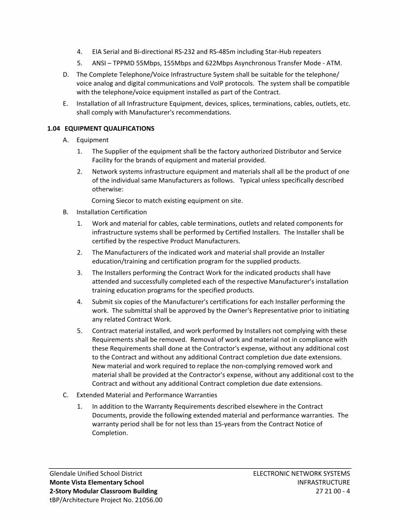
Glendale Unified School DistrictMonte Vista Elementary School 2-Story Modular Classroom BuildingtBP/Architecture Project No. 21056.00
ELECTRONIC NETWORK SYSTEMS INFRASTRUCTURE
27 21 00 - 4
4. EIA Serial and Bi-directional RS-232 and RS-485m including Star-Hub repeaters
5. ANSI – TPPMD 55Mbps, 155Mbps and 622Mbps Asynchronous Transfer Mode - ATM.
D. The Complete Telephone/Voice Infrastructure System shall be suitable for the telephone/ voice analog and digital communications and VoIP protocols. The system shall be compatible with the telephone/voice equipment installed as part of the Contract.
E. Installation of all Infrastructure Equipment, devices, splices, terminations, cables, outlets, etc. shall comply with Manufacturer's recommendations.
1.04 EQUIPMENT QUALIFICATIONS
A. Equipment
1. The Supplier of the equipment shall be the factory authorized Distributor and Service Facility for the brands of equipment and material provided.
2. Network systems infrastructure equipment and materials shall all be the product of one of the individual same Manufacturers as follows. Typical unless specifically described otherwise:
Corning Siecor to match existing equipment on site.
B. Installation Certification
1. Work and material for cables, cable terminations, outlets and related components for infrastructure systems shall be performed by Certified Installers. The Installer shall be certified by the respective Product Manufacturers.
2. The Manufacturers of the indicated work and material shall provide an Installer education/training and certification program for the supplied products.
3. The Installers performing the Contract Work for the indicated products shall have attended and successfully completed each of the respective Manufacturer's installation training education programs for the specified products.
4. Submit six copies of the Manufacturer's certifications for each Installer performing the work. The submittal shall be approved by the Owner's Representative prior to initiating any related Contract Work.
5. Contract material installed, and work performed by Installers not complying with these Requirements shall be removed. Removal of work and material not in compliance with these Requirements shall done at the Contractor's expense, without any additional cost to the Contract and without any additional Contract completion due date extensions. New material and work required to replace the non-complying removed work and material shall be provided at the Contractor's expense, without any additional cost to the Contract and without any additional Contract completion due date extensions.
C. Extended Material and Performance Warranties
1. In addition to the Warranty Requirements described elsewhere in the Contract Documents, provide the following extended material and performance warranties. The warranty period shall be for not less than 15-years from the Contract Notice of Completion.
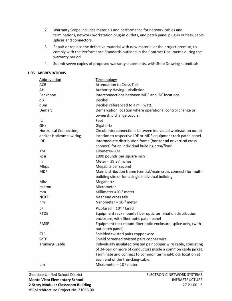
Glendale Unified School DistrictMonte Vista Elementary School 2-Story Modular Classroom BuildingtBP/Architecture Project No. 21056.00
ELECTRONIC NETWORK SYSTEMS INFRASTRUCTURE
27 21 00 - 5
2. Warranty Scope includes materials and performance for network cables and terminations, network workstation plug-in outlets, and patch panel plug-in outlets, cable splices and connectors.
3. Repair or replace the defective material with new material at the project premise, to comply with the Performance Standards outlined in the Contract Documents during the warranty period.
4. Submit seven copies of proposed warranty statements, with Shop Drawing submittals.
1.05 ABBREVIATIONS
Abbreviation TerminologyACR Attenuation to Cross TalkAHJ Authority Having JurisdictionBackbone Interconnections between MDF and IDF locationsdB DecibeldBm Decibel referenced to a milliwatt.Demarc Demarcation location where operational control change or
ownership change occurs.ft. FeetGHz GigahertzHorizontal Connection, Circuit Interconnections between individual workstation outletand/or Horizontal wiring location to respective IDF or MDF equipment rack patch panel.IDF Intermediate distribution frame (horizontal or vertical cross
connect) for an individual building area/floor.KM Kilometer-lKMkpsi 1000 pounds per square inchm Meter = 39.37 inchesMbps Megabits per secondMDF Main distribution frame (central/main cross connect) for multi-
building site or for a single individual building.Mhz Megahertzmicron Micrometermm Millimeter = l0-3 meterNEXT Near end cross talknm Nanometer = 10-9 meterpF Picofarad = 10-12 faradRTDE Equipment rack mounts fiber optic termination distribution
enclosure, with fiber optic patch panelRMSE Equipment rack mount fiber optic enclosure, splice only, (with-
out patch panel)STP Shielded twisted pairs copper wire.ScTP Shield Screened twisted pairs copper wire.Trunking-Cable Individually insulated twisted pair copper wire cable, consisting
of 24-pair or more of conductors inside a common cable jacket. Terminate and connect to common terminal-block location at each end of the truncking-cable.
um Micrometer = 10-6 meter
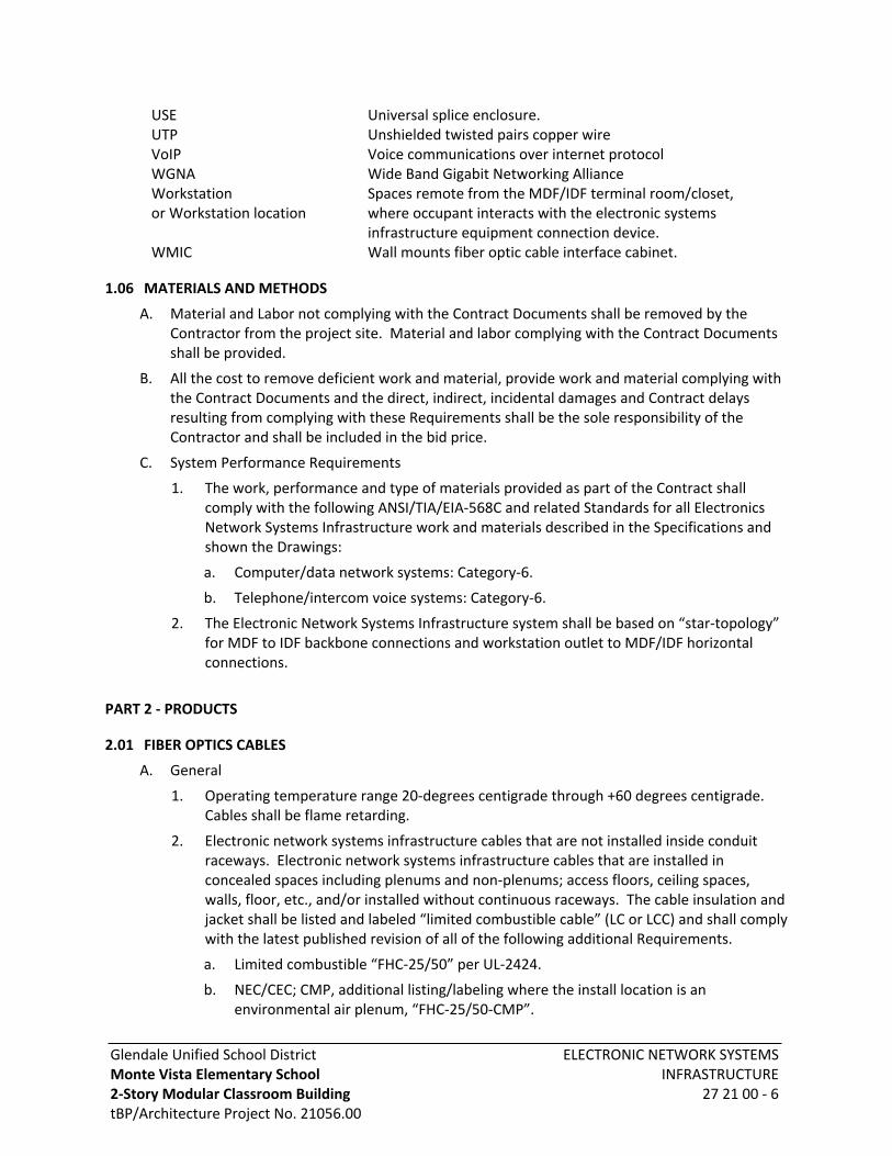
Glendale Unified School DistrictMonte Vista Elementary School 2-Story Modular Classroom BuildingtBP/Architecture Project No. 21056.00
ELECTRONIC NETWORK SYSTEMS INFRASTRUCTURE
27 21 00 - 6
USE Universal splice enclosure.UTP Unshielded twisted pairs copper wireVoIP Voice communications over internet protocolWGNA Wide Band Gigabit Networking AllianceWorkstation Spaces remote from the MDF/IDF terminal room/closet,or Workstation location where occupant interacts with the electronic systems
infrastructure equipment connection device.WMIC Wall mounts fiber optic cable interface cabinet.
1.06 MATERIALS AND METHODS
A. Material and Labor not complying with the Contract Documents shall be removed by the Contractor from the project site. Material and labor complying with the Contract Documents shall be provided.
B. All the cost to remove deficient work and material, provide work and material complying with the Contract Documents and the direct, indirect, incidental damages and Contract delays resulting from complying with these Requirements shall be the sole responsibility of the Contractor and shall be included in the bid price.
C. System Performance Requirements
1. The work, performance and type of materials provided as part of the Contract shall comply with the following ANSI/TIA/EIA-568C and related Standards for all Electronics Network Systems Infrastructure work and materials described in the Specifications and shown the Drawings:
a. Computer/data network systems: Category-6.
b. Telephone/intercom voice systems: Category-6.
2. The Electronic Network Systems Infrastructure system shall be based on “star-topology” for MDF to IDF backbone connections and workstation outlet to MDF/IDF horizontal connections.
PART 2 - PRODUCTS
2.01 FIBER OPTICS CABLES
A. General
1. Operating temperature range 20-degrees centigrade through +60 degrees centigrade. Cables shall be flame retarding.
2. Electronic network systems infrastructure cables that are not installed inside conduit raceways. Electronic network systems infrastructure cables that are installed in concealed spaces including plenums and non-plenums; access floors, ceiling spaces, walls, floor, etc., and/or installed without continuous raceways. The cable insulation and jacket shall be listed and labeled “limited combustible cable” (LC or LCC) and shall comply with the latest published revision of all of the following additional Requirements.
a. Limited combustible “FHC-25/50” per UL-2424.
b. NEC/CEC; CMP, additional listing/labeling where the install location is an environmental air plenum, “FHC-25/50-CMP”.

Glendale Unified School DistrictMonte Vista Elementary School 2-Story Modular Classroom BuildingtBP/Architecture Project No. 21056.00
ELECTRONIC NETWORK SYSTEMS INFRASTRUCTURE
27 21 00 - 7
c. NFPA-90A; ceiling cavity plenums, wall cavity spaces and raised floor cavity plenums, limited-combustible.
d. NFPA-5000; defines combustible material including wire and cable.
e. NFPA-75 computer rooms and electronic equipment room.
f. NFPA-13; spaces containing “limited combustible loading”.
g. Shall qualify as 100% recyclable materials disposal.
3. All fibers in a multi-fiber cable shall be fully operational within the performance characteristics specified prior to and after the cable is installed. The use of spare fibers in the cable to compensate for defective fibers is not permitted. Defective cables shall be removed and replaced with fully functional cables at no additional cost to the Contract.
4. Cables shall be UL listed, complying with National Electrical Code, ETL Tested and Certified to comply with Specified Requirements. ANSI/TIA/EIA-568C including related Standards, Amendments and TSB.
5. Each fiber shall be individually identified with factory color coding or factory imprinted label. The outer cable jacket shall be imprinted with date, Manufacturer's model and catalog number, along with agency listing identification.
6. Fiber optic cable shall be a product of the same Manufacturer, including portable patch cables.
7. The outer cable jacket shall be imprinted with date, Manufacturer’s model and catalog number and AHJ listing identification.
8. Cables installed in raceways or conduits below grade, through in-grade manholes or pull-boxes shall be rated for installation in water/wet locations.
9. Cables containing less than six fiber strands shall be provided with a color-coded outer jacket (red or orange).
10. Multimode (50/125)
a. 50/125-fiber optic cables optical fibers, graded index multimode optical glass fibers, 50.0-micron fiber core and 125-micron fiber cladding, 0.2 numerical apertures. Optical fibers shall be 100kpsi proof tested, with maximum 0.7-micron flaw size for dual operation at 850nm and 1300nm wavelengths.
b. Minimum bandwidth:@ 850nm-wavelength 500Mhz per KM length@ 1300nm-wavelength 500Mhz per KM length
c. Maximum attenuation:@ 850nm-wavelength 3.4dB @ 1 KM length@ 1300nm-wavelength 1.4dB @ 1 KM length
11. Single mode:
a. Fiber optic cables optical fibers, (8.3/125) single mode optical glass fibers, 8.3-micron core fiber and 125-micron fiber cladding, 0.11 numerical apertures. Optical fibers shall be 100kpsi proof tested, with maximum 0.7-micron flaw size. For operation at 1310nm and 1550nm wave lengths.

Glendale Unified School DistrictMonte Vista Elementary School 2-Story Modular Classroom BuildingtBP/Architecture Project No. 21056.00
ELECTRONIC NETWORK SYSTEMS INFRASTRUCTURE
27 21 00 - 8
b. Maximum attenuation:@ 1310nm- wavelength 0.5dB @ 1 KM length@ 1550nm - wavelength 0.4dB @ 1 KM length
c. Maximum dispersion@ 1310nm - wavelength 2.8ps/nm KM length@ 1550nm - wavelength 18.0ps/nm KM length
B. Loose Tube Gel-filled Cables
1. Multiple, loose tube buffer tubes, gel filled. Each buffer tube shall contain the same quantity of optical fibers, but not more than twelve optical fibers in each buffer tube.
2. Buffer tubes shall be cabled around a central dielectric strength member. The central strength member shall be centered along the length of the cable.
3. Aramid yarn, non-optical, strength fibers shall extend continuously along the length of the cable.
4. The cable interstitial spaces shall be flooded to inhibit water migration, with non-flammable water blocking gel.
5. Each optical fiber shall be individually UV cured acrylate coated, 250-micron diameter coating over fiber cladding.
6. A seamless black polyethylene outer layer jacket shall envelope the entire cable.
7. The cable shall be fungus resistant, UV resistant, and moisture resistant for installation indoors with or without an enclosed raceway and outdoors in underground enclosed raceway/conduit and manholes/pullboxes continuously flooded with water.
C. Indoor/Outdoor Cables
1. The cable shall be fungus resistant, UV resistant, and moisture resistant for installation indoors with or without an enclosed raceway and outdoors in underground enclosed raceway/conduit and manholes/pullboxes continuously flooded with water, and in conduits exposed to the sun.
2. Each optical fiber shall be primary coated with 500-micron uniform acrylate tight buffered and with elastomeric uniform 900-micron diameter tight buffered, secondary coating. Aramid yarn strength member elements shall be tensioned and symmetrically and uniformly distributed around the fibers, along the length of the cable.
3. An overall cable jacket uniformly extruded directly around and mechanically interlocked with the optical fibers/strength members. The extruded jacket shall form internal helical cusped ridges that interlock with the optical fibers and strength members. The inter-locking jacket shall not allow cable fibers to move axially within the cable jacket.
4. Cables containing more than twenty-four optical fibers shall be constructed with sub-cable fiber bundles. Each sub-cable bundle shall contain equal quantities of optical fibers, with a separate PVC jacket around each sub-cable. Sub-cable and sub-cable jacket construction shall match the overall Cable Requirements and Jacket Requirements.

Glendale Unified School DistrictMonte Vista Elementary School 2-Story Modular Classroom BuildingtBP/Architecture Project No. 21056.00
ELECTRONIC NETWORK SYSTEMS INFRASTRUCTURE
27 21 00 - 9
5. The cable shall be UL listed and comply with NEC and CEC and NFPA Requirements for each installation location shown in the Contract Documents. ETL tested and certified to comply with or exceed Specified Requirements.
a. NEC/CEC - OFNR (Vertical Riser Type Locations) OFNP (UL FHC-25/50 LC Plenum Type Locations and locations (where not continuously enclosed inside conduits for entire cable length).
b. NEC/CEC - OFNG (where continuously enclosed inside conduits for entire cable length).
D. Tight Buffered Cables
1. Each optical fiber shall be coated, 900-micron diameter uniform coating, with uniform tight buffering over the coating, uniform dielectric strength member surrounding the buffering coating and an overall jacket around each optical fiber assembly.
2. Individual multiple optical fiber assemblies shall be symmetrically arranged around a central dielectric strength member. The central strength member shall be centered along the length of the cable.
3. A dielectric strength member shall surround the fiber assemblies.
4. An outer dielectric jacket shall envelope the entire cable.
5. The cable shall be UL listed and comply with NEC and CEC and NFPA Requirements for each installation location shown in the Contract Documents. ETL tested and certified to comply with or exceed specified Requirements.
a. CEC - OFNP (UL FHC-25/50 LC Plenum type locations and locations where not continuously enclosed inside conduits for entire cable length).
2.02 COPPER WIRE CABLES (TWISTED PAIRS)
A. General
1. Conductors shall be copper wire, individually insulated and color-coded, with multiple conductors arrange in twisted pairs.
2. An overall non-conductive jacket shall encase the copper wires and any shielding (where shielding is specified) shall also be encased by the jacket.
3. Cables shall be UL listed, complying with NEC National Electrical Code, National Fire Protection Agency and NFPA Requirements for each installation location shown. ETL tested and certified to comply with or exceed Specified Requirements.
a. CEC – MPP/CMP (Plenum type locations and locations where not continuously enclosed inside conduit).
b. CEC – MPR/CMR (Vertical riser type locations).
c. ANSI/TIA/EIA-568C – Including related Standards, Amendments and TSB.
4. Electronic network systems infrastructure cables that are not installed inside conduit raceways. Electronic network systems infrastructure cables that are installed in concealed spaces including plenums and non-plenums; access floors, ceiling spaces, walls, floor, etc., and/or installed without continuous raceways. The cable insulation and jacket shall be listed and labeled “limited combustible cable” (LC or LCC) and shall comply with the latest published revision of all the following Additional Requirements.

Glendale Unified School DistrictMonte Vista Elementary School 2-Story Modular Classroom BuildingtBP/Architecture Project No. 21056.00
ELECTRONIC NETWORK SYSTEMS INFRASTRUCTURE
27 21 00 - 10
a. Limited combustible “FHC-25/50” per UL-2424.
b. NEC/CEC; CMP, additional listing/labeling where the install location is an environmental air plenum, “FHC-25/50-CMP”.
c. NFPA-90A; ceiling cavity plenums, wall cavity spaces and raised floor cavity plenums, limited-combustible.
d. NFPA-5000; defines combustible material including wire and cable.
e. NFPA-75 computer rooms and electronic equipment room.
f. NFPA-13; spaces containing “limited combustible loading”.
g. Shall qualify as 100% recyclable materials disposal.
5. Cables installed in air plenums, air-handling spaces and cables installed without raceway or conduit shall also be UL listed and labeled for installation in air plenums.
6. The outer cable jacket shall be imprinted with date, Manufacturer’s model and catalog number and agency (AHJ) listing identification.
7. Cables installed in raceways or conduits below grade, through in-grade manholes and pullboxes shall be rated for installation in water/wet locations.
8. Copper wire Electronic Network Systems Infrastructure cable shall be a product of the same Manufacturer, including portable patch cables.
9. The outer jacket of cables with less than 9-pair of conductors shall be color coded. The jacket color shall be different for each system type; multimedia; telephone/voice; computer/data network; and fiber cable jackets.
10. 300-volt RMS insulation material for each data conductor shall be the same material; shall be the same electrical characteristics and shall be the same dielectric constant, for all data conductors contained within the respective common cable jacket, along the entire installed length of the cable. Data cables employing differing insulation materials for individual data conductors contained within a common cable jacket are not acceptable and shall not be provided.
11. Propagation and “Skew” Rate
a. Skew rate (nominal velocity of propagation delay) between any twisted pair in a combination of 4-twisted pair conductors grouped in the same cable, shall not exceed 35 nano seconds between any wire pair contained in the conductor group, and as required by the cable Category rating, over a cable length of 328-feet (100 meters), for all frequencies up to the cable maximum frequency rating.
b. Nominal velocity of propagation, 70% of the speed of light.
12. Copper wire cables with more than 25-twisted pairs of conductors shall be constructed with 25-pair binder groups of conductors. The cable binder groups shall be enclosed in colored binders and assembled to form a single cable. The twisted pair/binder groups shall be enclosed with multi-layer dielectric protective sheaths underneath a cable jacket enclosing the entire cable assembly. A corrugated metal 100% shield shall be provided under the cable jacket enclosing all conductors.
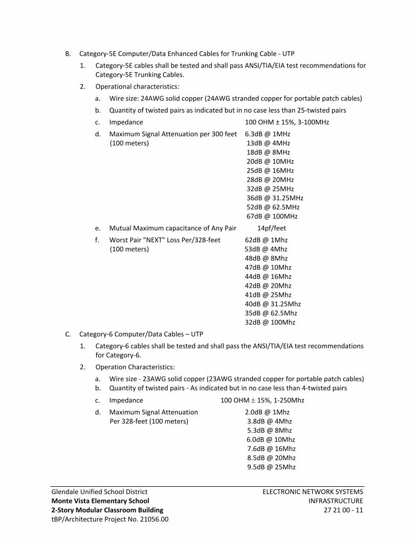
Glendale Unified School DistrictMonte Vista Elementary School 2-Story Modular Classroom BuildingtBP/Architecture Project No. 21056.00
ELECTRONIC NETWORK SYSTEMS INFRASTRUCTURE
27 21 00 - 11
B. Category-5E Computer/Data Enhanced Cables for Trunking Cable - UTP
1. Category-5E cables shall be tested and shall pass ANSI/TIA/EIA test recommendations for Category-5E Trunking Cables.
2. Operational characteristics:
a. Wire size: 24AWG solid copper (24AWG stranded copper for portable patch cables)
b. Quantity of twisted pairs as indicated but in no case less than 25-twisted pairs
c. Impedance 100 OHM ± 15%, 3-100MHz
d. Maximum Signal Attenuation per 300 feet 6.3dB @ 1MHz (100 meters) 13dB @ 4MHz
18dB @ 8MHz 20dB @ 10MHz 25dB @ 16MHz 28dB @ 20MHz 32dB @ 25MHz 36dB @ 31.25MHz 52dB @ 62.5MHz 67dB @ 100MHz
e. Mutual Maximum capacitance of Any Pair 14pf/feet
f. Worst Pair "NEXT" Loss Per/328-feet 62dB @ 1Mhz (100 meters) 53dB @ 4Mhz
48dB @ 8Mhz47dB @ 10Mhz 44dB @ 16Mhz42dB @ 20Mhz41dB @ 25Mhz40dB @ 31.25Mhz35dB @ 62.5Mhz32dB @ 100Mhz
C. Category-6 Computer/Data Cables – UTP
1. Category-6 cables shall be tested and shall pass the ANSI/TIA/EIA test recommendations for Category-6.
2. Operation Characteristics:
a. Wire size - 23AWG solid copper (23AWG stranded copper for portable patch cables)b. Quantity of twisted pairs - As indicated but in no case less than 4-twisted pairs
c. Impedance 100 OHM 15%, 1-250Mhz
d. Maximum Signal Attenuation 2.0dB @ 1MhzPer 328-feet (100 meters) 3.8dB @ 4Mhz
5.3dB @ 8Mhz 6.0dB @ 10Mhz7.6dB @ 16Mhz8.5dB @ 20Mhz9.5dB @ 25Mhz

Glendale Unified School DistrictMonte Vista Elementary School 2-Story Modular Classroom BuildingtBP/Architecture Project No. 21056.00
ELECTRONIC NETWORK SYSTEMS INFRASTRUCTURE
27 21 00 - 12
10.7dB @ 31.25Mhz15.4dB @ 62.5Mhz19.8dB @ 100Mhz29.0dB @ 200Mhz32.8dB @ 250Mhz
e. Mutual Maximum Capacitance of Any Pair 5.0nF/100m
f. Worst Pair "NEXT" Loss Per/328-feet (100 meters)74.3dB @ 1Mhz65.3dB @ 4Mhz60.8dB @ 8Mhz59.3dB @ 10Mhz56.2dB @ 16Mhz54.8dB @ 20Mhz53.3dB @ 25Mhz51.9dB @ 31.25Mhz47.4dB @ 62.5Mhz44.3dB @ 100Mhz39.8dB @ 200Mhz38.3dB @ 250Mhz
2.03 FIBER OPTIC FIBER SPLICES
A. General
1. Fiber optic cable splices shall be UL listed, complying with National Electrical Code, ETL tested and certified to comply with or exceed specified Requirements, ANSI/TIA/EIA-568B including related Standards, Amendments and TSB.
2. Fiber optic splices shall be the products of the same Manufacturer.
B. Mechanical Splice
1. Mechanically splice each fiber with a splice suitable for use with the type of fiber optic fibers. Re-enterable and reusable splice. Splice shall be recommended as compatible with the optical fibers by the Manufacturer. Splice shall not require the use of adhesives. Splice shall provide integral strain relief.
2. Performance Requirements after installation:
a. Operating temperature range minus 20-degrees centigrade through plus 60-degrees centigrade.
b. Loss variation over temperature range, 0.05dB or less at specified wave lengths.
c. Insertion loss, 0.3dB or less at specified cable wave lengths.
d. Reflection (return loss), -40dB at specified cable wave lengths.
C. Fusion Splicing
1. Fusion splicing shall be performed with equipment providing the following features:
a. Cleaving and cleaning optical fiber.
b. Integral splice optimization verification system with local injection and detection.
c. Projection screen optics and fiber core alignment system.
Glendale Unified School DistrictMonte Vista Elementary School 2-Story Modular Classroom BuildingtBP/Architecture Project No. 21056.00
ELECTRONIC NETWORK SYSTEMS INFRASTRUCTURE
27 21 00 - 13
d. Fiber cleaning/stripping.
e. Cleaning fiber ends and fusing of fiber together with an electric arc.
2. Fusion splice insertion loss as measured at the completion of the splice shall be less than 0.1dB at specified cable wave lengths.
2.04 FIBER OPTIC FIBER CONNECTORS AND INTERCONNECTION COUPLERS
A. General
1. The connectors and interconnection couplers shall be compatible, maintain the same Performance Category rating and be compatible with the corresponding fiber-optic cable type attached to the connectors.
2. Fiber optic cable connectors and interconnection couplers shall be UL listed, complying with National Electrical Code, ETL tested and certified to comply with or exceed Specified Requirements. Connectors and couplers shall comply with ANSI/TIA/EIA-568C, related Standards, Amendments, TSB, and Fiber Optic Connector Intermate Standard (FOCIS) documentation.
3. Fiber optic connectors and couplers shall be the product of the same Manufacturer.
4. Shall be UL listed and comply with UL94V-0.
5. Color code connectors for fiber optic cables to match the respective fiber optic strand/ jacket color.
B. Multimode Fiber Optic Fiber Connectors
1. LC – Small Form Factor (SFF) termination connector:
a. Ceramic oxide 1.25mm ferrule. Mechanical durability not less than 500-mating cycles. Insertion loss of mated connector shall be less than 0.3dB at specified wave-lengths.
b. Strain relief boot, long boot type unless indicated otherwise, short or angled boot type to match the connector installation application. Provide duct cover cap for each connector.
c. Locking type to automatically align mating fibers in the fiber cable and prevent accidental rotation and pullout.
C. Fiber Optic Fiber Interconnection Couplers
1. Interconnection couplers shall be “like-to-like” compatible and shall provide "plug-in" coupling of two fiber optic cable connectors terminated with fiber optic fibers front-to-rear "in-line" together. The coupler shall provide interlocking, automatic optical self-alignment of two mating fiber optic connectors.
2. The centerline to centerline spacing of the interconnection couplers shall allow removal and insertion of portable patch cords, fiber cable connectors for both “single” and “duplex” type fiber adapter connectors without interfering with adjacent connectors.
3. Patch panel mounted interconnections couplers shall be factory pre-mounted to a modular nominal 0.09-inch-thick metal panel, couplers aligned and anchored on the plate.
Glendale Unified School DistrictMonte Vista Elementary School 2-Story Modular Classroom BuildingtBP/Architecture Project No. 21056.00
ELECTRONIC NETWORK SYSTEMS INFRASTRUCTURE
27 21 00 - 14
a. The metal panel shall be predrilled for Standard EIA mounting in high-density 19-inches wide metal patch panel frames.
4. Interconnection couplers in workstation outlets shall be installed in outlet boxes with cover plates.
5. Provide removable dust caps for the front side of each coupler.
2.05 COPPER WIRE OUTLET CONNECTORS
A. General
1. Connectors shall comply with FCC part 68 Subpart F for gold plating.
2. Connectors shall be UL listed and shall comply with UL94V-0.
3. Provide a removable blank dust cover for each plug-in outlet insert. The dust cover shall protect the insert from contamination until a workstation or patch cord is "plugged" into the outlet.
4. Copper wire outlet connectors shall be color coded to distinguish telephone/voice separately from computer/data. The outlet coverplate shall be engraved to identify tele-phone/voice, computer/data and other infrastructure outlets separately.
5. Copper wire outlet connectors shall be UL listed, complying with National Electrical Code, ETL tested and certified to comply with or exceed Specified Requirements, ANSI/TIA/EIA-568C including related Standards, Amendments and TSB.
6. Copper wire outlet connectors shall be the product of the same Manufacturer.
B. Universal Outlet Connector (for twisted pair Copper Wire Premise/Workstation Wiring and copper wire patch panels).
1. General
a. Connections for twisted pairs copper conductors shall provide a universal outlet connector between the building premise copper wire, and plug-in workstation locations. Patch panel/equipment plug-in connectors. The connector components shall assemble with "snap-in" spring loaded retainers to prevent dislocation during insertion or removal of external plug-in devices.
b. The contacts shall be gold plated with a 250-insertion/withdrawal cycle rating.
c. Unless specifically noted otherwise the universal outlet connector shall comply with ANSI/TIA/EIA-568C, related Standards, Amendments, and TSB.
d. Operational characteristics shall match or exceed and shall be compatible with the respective twisted pair’s cable.
e. Each universal outlet connector shall consist of three major components.
1) Universal edge connector assembly.
2) Plug-in adapter inserts.
3) Connector housing.
f. Provide snap-in blank removable insert covers for connector installed without plug-in adapter inserts.

Glendale Unified School DistrictMonte Vista Elementary School 2-Story Modular Classroom BuildingtBP/Architecture Project No. 21056.00
ELECTRONIC NETWORK SYSTEMS INFRASTRUCTURE
27 21 00 - 15
2. Universal edge connector:
a. Insulated assembly shall connect to the premise copper wire. The connectors shall be multiple plug type connector contacts, one contact (total of eight contacts) for each individual premise wire connection interconnected to the individual wire terminations.
b. Connector shall provide insertion of individual insulated copper wire, gas tight, 110-style punch down/displacement termination, for 22-26AWG insulated premise wire.
c. The edge connector assembly shall provide termination of eight separate wire conductors, twisted or untwisted pairs, solid or stranded, shielded or unshielded, with color codes and numbered identification of each contact. Integral cable/ conductor strain relief to prevent pullout of terminated premise wire conductors.
3. Plug-in adapter inserts:
a. Plug-in adapter inserts shall be internally factory connected to the universal edge connector assembly to adapt the universal connector to the specific outlet type configuration (i.e., "RJ" style computer/data, telephone/voice, (multimedia) modular jacks, etc.)
b. Inserts shall be certified to match premise wire type connected to the universal edge connector.
c. Inserts shall provide correct pin-to-pin connections, electrical and mechanical matching characteristics for the specific equipment connected to the respective out-let.
d. Inserts for different infrastructures shall be color coded with different colors from each other, for system identifications.
e. Plug-in adapters insert type:
1) Computer/data network systems:a) ANSI/TIA/EIA-568C, female modular jack 8-position/contact "RJ-45" style,
keystone, “snap-in” mounting.
2) Telephone/intercom voice systems:a) ANSI/TIA/EIA-568C female modular jack 8-position/contact RJ-45, key-
stone, “snap-in” mounting.
4. Connector housing:
a. Connector housing shall contain the universal edge connector assembly and the plug-in adapter inserts in a rigid assembly. Connector housing shall provide integral cable strain relief for the premise wiring connection.
b. The connector housing shall mount to a metal panel, metal device cover plate or plastic device cover plate with spring loaded snap-in retainers. Nominal depth of connector housing behind the mounting panel and/or device cover plate shall not exceed 1.625 inches including premise wiring termination depth Requirements.
Glendale Unified School DistrictMonte Vista Elementary School 2-Story Modular Classroom BuildingtBP/Architecture Project No. 21056.00
ELECTRONIC NETWORK SYSTEMS INFRASTRUCTURE
27 21 00 - 16
2.06 FIBER OPTIC FIBER DISTRIBUTION ENCLOSURES
A. General
1. Fiber optic fiber distribution enclosures shall be UL listed, complying with National Electrical Code, ETL tested and certified to comply with or exceed Specified Requirements, ANSI/TIA/EIA-568C including related Standards, Amendments and TSB.
2. Fiber optic fiber distribution enclosures shall be the product of the same Manufacturer.
B. Equipment Rack Mount Fiber Optic Termination Distribution Enclosure - RTDE
1. The RTDE enclosure shall mount in an EIA Standard 19-inches wide enclosed or open frame equipment rack assembly. The RTDE enclosure shall be metal, painted finish, Manufacturers standard color.
2. The RTDE shall provide the following self-contained functions internal to the RTDE assembly.
a. Fiber cable termination.
b. Fiber cable "pig-tail" splicing.
c. Fiber cable patch panel.
d. Fiber cable management, training and strain relief.
e. Individual fiber and patching port identification numbers, color-coding of incoming trunk and out-going distribution fiber ports.
f. Plug-in fiber optic interconnection couplers for port-to-port patching with portable fiber optic patch cords.
3. Fiber splice drawers:
a. Horizontal sliding metal drawers adjustable to approximately 30-degree angle when fully open, and removable for easy access. Each drawer shall contain two fiber optic splice trays with tray holders.
b. Drawers shall stack vertically one above the other in the RTDE and allow sufficient slack in all fiber cables for removal of the drawer and splice trays.
c. Provide one sliding drawer and two splice tray assemblies for each group (24-individual fibers or fewer fibers per group) of fiber optic fibers terminated in the equipment rack, but in no case provide not fewer than two sliding drawers with splice tray assemblies in each RTDE.
4. Fiber cable patch panel
a. Metal panel shall provide a patch port for each fiber consisting of metal panel mounted fiber optic interconnection couplers for each fiber optic fiber indicated to be terminated at the RTDE.
b. The fiber optic fiber interconnection coupler shall be provided to match and be compatible with the fiber cable connectors. Quantity shall match quantity of terminated fibers, unless indicated otherwise on the equipment rack schedules.
c. Nominal panel thickness 0.09 inches.
d. Provide a minimum of sixteen unused spaces for additional couplers in the patch panel.
Glendale Unified School DistrictMonte Vista Elementary School 2-Story Modular Classroom BuildingtBP/Architecture Project No. 21056.00
ELECTRONIC NETWORK SYSTEMS INFRASTRUCTURE
27 21 00 - 17
5. Nominal height of the RTDE shall not be exceeded, as follows:Quantity of Patch Ports Quantity of Splice Drawers Nominal Height
24 2 11 inches48 2 11 inches72 3 14 inches
144 6 28 inches
C. Equipment rack mount fiber optic, splice only (for use only where fiber patch panel is not required) enclosure - RMSE
1. The RMSE enclosure shall mount in an EIA standard 19-inches wide enclosed or open frame rack assembly. The enclosure shall be metal, painted finish, Manufacturer's standard color.
2. The RMSE shall provide the following self-contained functions internal to the RMSE assembly:
a. Fiber cable splicing for "thru splicing" of fiber optic cables where the cables do not terminate in the equipment rack.
b. Fiber cable management, training and strain relief.
3. Fiber splice drawers
a. Horizontal sliding metal drawers adjustable to approximately 30-degree angle when fully open and removable for easy access. Each drawer shall contain two fiber optic splice trays with splice tray holders.
b. Drawers shall stack vertically one above the other in the RMSE and allow sufficient slack in all fiber cables for removal of the drawers and splice trays.
c. Provide one sliding drawer and two fiber optic splice tray assemblies for each group 24-individual fibers or fewer fibers per group) for fibers optic fiber routed through but not terminated in the equipment rack, but in any condition provide not fewer than two sliding drawers with splice tray assemblies in each RMSE.
4. Nominal height of the RMSE shall not be exceeds, as follows:Quantity of Thru Splices Quantity of Splice Drawers Nominal Height
24 2 4 inches48 2 4 inches72 4 8 inches96 4 8 inches
2.07 COPPER WIRE PATCH PANELS
A. General
1. Copper wire patch panels shall be UL listed, complying with National Electrical Code, ETL tested and certified to comply with or exceed Specified Requirements, ANSI/TIA/EIA-568C including related Standards, Amendments and TSB.
2. Copper wire patch panels shall be the product of the same Manufacturer.
B. Equipment Rack Mounted Patch Panel
1. Standard EIA 19-inches wide metal panel, Manufacturers standard color. Pre-punched for copper wire outlet connectors. Panel shall mount on an EIA standard 19-inches wide
Glendale Unified School DistrictMonte Vista Elementary School 2-Story Modular Classroom BuildingtBP/Architecture Project No. 21056.00
ELECTRONIC NETWORK SYSTEMS INFRASTRUCTURE
27 21 00 - 18
enclosed or open frame equipment rack assembly. Nominal 24-copper wire outlet connectors in a horizontal row, quantity of rows as required for total quantity of connectors. Provide not less than two spare empty rows for future copper wire outlet connectors.
2. The patch panel shall provide the following self-contained functions.
a. Copper wire cable termination including conductor/shield termination and strain relief.
b. Plug-in copper wire outlet connectors for port-to-port patching with copper wire portable patch cords.
3. Patch panel height shall be based on the quantity of copper wire outlet connectors described plus the specified space for future outlets and shall not exceed the following dimension height:Outlet Quantity Nominal Patch Panel Height48-patch ports in each patch panel Shall not exceed 3.5-inches for each 48-port panel.
4. Horizontally mounted, cable support metal bracket shall be provided for 48-outlet/ connector groupings between fiber and copper wire. The brackets shall be bolted to the equipment rack located at the backside of the patch panel; the brackets shall support and provide strain relief for each incoming copper wire cable connecting to the patch panel left-right cable entrance pathway.
5. The copper wire connector installed in the patch panel shall be the same configuration, Manufacturer and type as the corresponding copper wire connector provided in the remote workstation outlet locations connecting to the respective patch panel outlet, unless indicated otherwise.
2.08 EQUIPMENT RACK
A. General
1. An equipment grounding bus, nominal 19-inches long, UL labeled as a ground terminal bus, shall be provided on each equipment rack. The ground bus shall be bolted to the rack main metal frame member with 1-inch standoff non-insulating bolts. Provide a minimum of ten drilled and tapped bolt holes in the ground bus with ground lug bolts, for connection of equipment grounding conductors to the ground bus, size to accept ground conductors #14-#4AWG.
2. Vertically mounted, cable management metal rings (aluminum or stainless steel) shall be provided full height, continuously along the front and rear of each vertical rail of the equipment rack. The rings shall be bolted to the equipment rack. The rings shall train and dress portable patch cords connecting between outlet connectors located in the equipment rack or in adjacent equipment racks.
3. Provide horizontal cable management panels with multiple cable training rings on each panel (not less than five rings for each panel). Management panels (for up to 24-outlet grouping) nominal 19-inches wide by 1.75-inch high by 3-inches deep and/or (for up to 48 outlet groupings) 3.5-inches high by 3-inches deep, for EIA rack installation. Rings shall provide horizontal routing and support by grouping portable patch cords connecting between patch ports in the same equipment rack or adjacent racks. Patch cords shall be grouped and bundled with “Velcro” tie wraps and shall not overlap patch fields or rack

Glendale Unified School DistrictMonte Vista Elementary School 2-Story Modular Classroom BuildingtBP/Architecture Project No. 21056.00
ELECTRONIC NETWORK SYSTEMS INFRASTRUCTURE
27 21 00 - 19
mounted equipment. The panels shall be installed on both the front and rear of the equipment racks, mounted both above and below horizontally between groups of patch ports as follows:
a. One cable management panel (front and rear of rack) for each group of 48-fiber optic outlet patch ports adjacent to copper wire patch panel.
4. The entire rack assembly including any support arms shall comply with seismic earthquake structural standards at the install location.
a. The assembly shall provide support for the weight of the equipment installed on the rack, but in no case less than 500 pounds of equipment, plus the weight of the rack and connecting cables. A 2.0 times safety factor shall be included in the equipment rack assembly structural design.
b. Mini-equipment racks shall be rated for not less than 200 pounds of equipment, plus a 2.0 times safety factor shall be included in the mini-equipment rack.
5. Provide Surge Protection Device with RF Suppresser (SPD) and Power Distribution Unit (PDU). 120-volt 1-phase, 20-amp 60Hz AC plug horizontal strip, mounted in each equipment rack. Each unit shall contain not less than eight “plug-ins” on the rear of the SPD and not less than two plug-ins on the front of the SPD protected outlet plugs.
a. Provide two SPD/PDU units in each equipment rack, to supply “dual-corded” equipment.
6. Provide pre-drilled mounting holes the entire length of equipment vertical mounting frames, EIA-310D 19-inches (nominal) wide standard spacing for indicated equipment. Racks shall provide 17.75-inches (nominal) equipment horizontal mounting space between vertical rails.
7. Provide a copper ground – bus for equipment bonding, in each equipment pack.
8. Equipment racks shall be Manufacturer’s standard rust inhibitor primer. Manufacturer’s standard color-finish paint over primer, unless noted otherwise.
B. Mini-Equipment Racks Sectional – Surface Wall Mount (Indoor Locations Only)
1. The mini-equipment rack shall be fully metal enclosed, tamper resistant, wall surface mounted and multiple section construction. The rack shall consist of three sections; a fixed wall mounting pan; a hinged center section and a hinged door. The rack shall provide a minimum of 30-inches clear internal depth for mounting of equipment inside the rack. Provide brackets inside the pan for stress relief, training/lacing, support of cables.
2. The mini equipment racks nominal dimensions shall be as follows:
a. Overall depth 33-inches.
b. Overall width 22-inches.
c. 24-inches minimum over all height, for termination of up to a quantity of 144-copper wire workstation patch panel outlets and up to a quantity of eighteen individual fiber strands, combined into a mini-equipment rack.
d. 30-inches minimum overall height, for termination of up to a quantity of 192-copper wire workstation patch panel outlets and up to a quantity of eighteen individual fiber strands combined, into the mini-equipment rack.
Glendale Unified School DistrictMonte Vista Elementary School 2-Story Modular Classroom BuildingtBP/Architecture Project No. 21056.00
ELECTRONIC NETWORK SYSTEMS INFRASTRUCTURE
27 21 00 - 20
e. 48-inches minimum overall height, for termination of up to quantity of 288-copper wire workstation patch panel outlets and up to a quantity of eighteen individual fiber strands combined, into the mini-equipment rack.
3. Fixed wall, surface mounted pan section, nominal 3-inches pan depth, metal enclosed on all sides and back, open front; shall anchor the rack to the wall; provide support for the hinged center rack section and provide knockouts for side/top/bottom and rear conduit/ raceway entrances.
4. Center section, metal enclosed on all sides, open front and rear, nominal 18-inches depth, full height and width hinged attachments to the pan-section, to provide hinged 90 degrees open-close operation of the center section on the pan and allow access to the front and rear of equipment and terminations mounted inside the center section. Two internal vertical, front mounted, pre-drilled equipment mounting frame rails. Self-locking with release latch accessible from inside cabinet.
5. Front access door section, metal, full height and width hinged 90 degree open-close operation attached to the center section. The door shall allow for nominal 3-inches minimum of interior projections extending from the front face of the internally mounted equipment located behind the front access door when the access door is in the closed position. Smoke/gray impact resistant, tamper resistant see-through windows in the door front. Key-locking front of door exterior access.
6. Minimum 16-gauge metal, fully welded construction; Manufacturer’s standard rust inhibitor “prime” base coating, with “finish” color black or as selected by Architect. The equipment racks shall provide support for the weight of the equipment installed in the rack, but in no case less than 200 pounds of equipment plus the weight of the rack and connecting cables.
7. Provide two 120-volt 60Hz AC motor direct driven air ventilation, “muffin” style, nominal 4 inches square, exhaust air fans. Flush mount fans in the top of each equipment rack. The fans shall be low speed, low noise type with wire guards to prevent accident contact with the fan blades. The fan motor shall be high impedance, self-protecting type motors. Provide “SO” cord with plug caps to connect from the fans to the 120-volt plug-strip inside the equipment rack.
8. Provide cooling air intake louvers with removable air filters and air filter holder, mounted in the bottom of the rack. The louver shall be protected with internal screening to prevent the intentional insertion of foreign objects into the housing.
9. The mini-equipment rack shall be easily convertible in the field, to allow for “left” or “right” center section and/or door section hinge operation. Provide a minimum of two key-locks on each hinged section to prevent unauthorized access into the unit. Provide gasketing on all “mating” cabinet interfaces to insure proper cooling airflow through the air filters.
10. Mini-equipment racks as manufactured by Hoffman/Pentair; or Middle Atlantic Products Inc.; or B-Line.
Glendale Unified School DistrictMonte Vista Elementary School 2-Story Modular Classroom BuildingtBP/Architecture Project No. 21056.00
ELECTRONIC NETWORK SYSTEMS INFRASTRUCTURE
27 21 00 - 21
C. Plug Strip Surge Protection Device (SPD)
1. General
a. Self-contained unit combining plug-in SPD strip and power distribution unit PDU. Rated 20 amp, nominal 120 volt +10%, 60Hz, AC, 2400 watts full continuous load or 20 amp, nominal 208-volt 10%, 60Hz, AC, 4800-watts full continuous load. Note: 120-volt or 208-volt ratings as indicated on the Drawings.
b. Internal 20-amp resettable overload protection circuit breaker. Red illuminated on-off switch. Nine foot, 12AWG three conductor grounded, high abuse heavy duty jacketed AC, line cord with cap. Multi-outlet receptacles, suitable for use with the following types of plug-in loads; data processing equipment, audio/video equipment, test instruments, medical equipment, photo graphic equipment and “switching type” power supplies.
c. Protected outlet shall be 120-volt NEMA 5-15R 15-amp or 20-amp 120-volt NEMA 5-20R AC 60Hz receptacles; or for 208-volt, NEMA 6-15R 15 amp or 208-volt NEMA 6-20R 20-amp receptacles as applicable for connected equipment loads. Provide not less than eight protected outlet plugs on each unit. Each individual or group of two receptacles (duplex) shall be connected to separate protected load isolated filter banks.
d. Each duplex shall be isolated from the other output receptacles, minimum isolation of 25dB at 1MHz line to line, line to neutral, line to ground and neutral to ground.
e. Non-blocking plug-in locations/orientation, for plug-in self-contained “power-brick”, equipment power supplies.
f. As manufactured by Libert, or TRIPP LITE.
2. Operation
Self-contained RFI and EMF shielded housing with mounting slots for temporary mounting of the unit. Protected outlet receptacles shall supply over current protected and filtered, electrical line voltage power to the connected equipment. Line noise RFI and EMI interference filtering suppression, surge protection device and spike protection shall occur in all three modes of operation line to ground, line to neutral and neutral to ground rated as follows:
a. 13,000-amp, 210 joules (watt-seconds) peak withstands capacity.
b. Transient response time less than 5-nano seconds.
c. 140-volt AC RMS initiate spikes suppression 330 volt maximum let through.
d. RFI and EMI Suppression-Provide spectrum analysis test dB attenuation reports showing RFI filtering over specified frequencies.
e. Diagnostic indicator lights located on the SPD housing shall provide alarm alert for each of the following conditions:
1) Loss of AC power.
2) Damage, malfunction in the SPD suppression circuits.
3) Improper AC electrical outlet wiring.

Glendale Unified School DistrictMonte Vista Elementary School 2-Story Modular Classroom BuildingtBP/Architecture Project No. 21056.00
ELECTRONIC NETWORK SYSTEMS INFRASTRUCTURE
27 21 00 - 22
f. Self-contained metering and communications
1) Ampere-meter demand load meter to monitor plug-in demand load.
2) Digital Fast Ethernet LAN RJ-45 communications port for Ethernet SNMP network monitoring of electrical status. Multi-user site wide software license, compatible with PC-computer and IP-WEB HTTP protocols.
g. Standards Testing, Listing and Certification Compliance:
1) IEEE 587A and B compliance.
2) UL 1449 transient voltage surge suppressers.
3) UL 1363 temporary power taps.
4) UL 1283 electromagnetic interference filters.
3. Rack Mounted SPD/PDU
a. SPD/PDU units installed in equipment racks shall comply with all of the same Performance Requirements including as follows.
1) EIA/TIA – Equipment rack mount style (19-inches or 24-inches as applicable).
2) Minimum of two front mounted outlets and not less than six rear mounted out-lets.
3) Position in each equipment rack as directed by Owner’s Representative.
D. Power Distribution Unit (PDU)
1. General
a. Self-contained unit combining main circuit breaker, multiple plug-in individual circuit breaker branch protection load receptacles, PDU metering status monitoring and network communication. All PDU components self-contained in a NEMA-1 metal enclosure.
b. Non-blocking plug-in locations oriented for plug-in self-contained “power-brick” equipment supplies.
c. Standards Testing
1) UL 60950-1 Information Technology Equipment.
2) CAN/CSA-C22.2 No.60950-1-03 Information Technology Equipment.
3) FCC, Title 47, Part 15 Subpart B for Class B operation as defined by ANSI Standard C63.4
4) ROHS Complaint
5) ISTA Procedure 1A and 2A
d. Provide two PDU units in each equipment rack, to supply two SPD units in each equipment rack.
e. Shall be a product of the same Manufacturer as the SPD unit. As manufactured by Liebert, or TRIPP LITE.
Glendale Unified School DistrictMonte Vista Elementary School 2-Story Modular Classroom BuildingtBP/Architecture Project No. 21056.00
ELECTRONIC NETWORK SYSTEMS INFRASTRUCTURE
27 21 00 - 23
2. System Description
a. Remote monitoring and/or control capabilities for power distribution at each load/ equipment rack level. For data/network equipment line voltage plug-in and SPD line voltage plug-in electrical distribution.
b. PDU shall meter and monitor electrical attributes of an individual Rack PDU, including real-time remote and local display of monitoring of aggregate and branch electrical parameters (status, thresholds, alarms) including voltage, ampere, and kW. Rack equipment PDU and Branch load monitoring and control.
c. Self-contained metering and communications
1) Local display ampere-meter demand load meter to monitor plug-in demand load and total PDU load.
2) Digital Fast Ethernet LAN RJ-45 communications port for Ethernet SNMP and IP network monitoring of electrical status. Multi-user site-wide software license, compatible with PC-computer and IP-WEB HTTP protocols.
3) Provide network array-interface for connection of multiple PDU units positioned in the same location.
d. Nine-foot input power (heavy duty high abuse) cord with appropriate conductors and input NEMA plug-in connection. Provide input overload protection with Hydraulic-Magnetic main input circuit breaker. Provide load output NEMA plug-in branch connection with overload circuit breaker protection for each load receptacle.
e. Equipment rack mounting horizontal position form factor.
3. Electrical Power ratings shall be as follows and as additionally indicated on Drawings. Refer to Drawings for twist-lock verses straight-blade configurations.
a. Single main input circuit breaker 30-amp 208/120 volt 1-phase 4-wire grounded 60Hz AC.
b. Branch load circuit breakers with a single plug-in receptacles for each load circuit breaker. Balance loads on each circuit phase.
1) Three 20 amp 1-pole circuit breaker and three 120-volt NEMA 5-20R receptacles. Also provide matching cap.
2) Two 20 amp 2-pole circuit breaker and two 208-volt NEMA 14-20R receptacle. Also provide matching cap.
3) One 30 amp 2-pole circuit breaker and one 208-volt NEMA 14-30R receptacle. Also provide matching cap.
4) Additional circuits and receptacles as indicated on Drawings.
4. PDU units installed in equipment racks shall comply with all of the same Performance Requirements including:
a. EIA/TIA – equipment racks horizontal mount style (19-inch or 24-inch) as applicable.
b. Position in each equipment rack as directed by Owner’s Representative.
5. Provide two Category-6 4-pair UTP 15-foot-long portable patch cable connects, PDU to respective network patch panel port.
Glendale Unified School DistrictMonte Vista Elementary School 2-Story Modular Classroom BuildingtBP/Architecture Project No. 21056.00
ELECTRONIC NETWORK SYSTEMS INFRASTRUCTURE
27 21 00 - 24
2.09 WALL MOUNT FIBER OPTIC CABLE INTERFACE CABINET (WMIC)
A. General
1. Metal (14 gauge) enclosure, with full height hinged metal door. Door shall be pad-lockable. Nominal size 12-inches deep by 18-inches wide by 36-inches high. Enclosure shall mount directly on the wall.
2. WMIC shall be UL listed, complying with National Electrical Code, ETL tested and certified to comply with or exceed Specified Requirements, ANSI/TIA/EIA-568C including related Standards, Amendments and TSB.
3. Interface cabinets shall be the product of the same Manufacturer.
B. The WMIC shall provide the following self-contained functions internal to the WMIC enclosure.
1. Fiber cable splicing for "through splicing" of non-UL listed fiber optic cables, where the cables do not terminate in the building.
2. Fiber cable management, training, and strain relief.
3. Transition from non-UL flame spread listed fiber optic cable, to UL flame spread listed fiber optic cables where the cables terminate in the building.
C. Cable routing rings shall organize optic fibers in a 360-degree loop inside the WMIC housing and provide cable strain relief.
D. Fiber Optic Splice Trays
1. Provide fiber optic cable splice trays.
2. Tray holders shall provide mounting and support for each splice tray.
3. Provide two splice trays for each group (twenty-four or less fibers per group) fiber optic fibers routed through the WMIC, but in no case provide not less than four splice trays in the WMIC.
2.10 SPLICE TRAY FIBER OPTIC FIBERS
A. General
1. Trays shall be suitable for installation in USE, WMIC, RMSE and RTDE enclosures.
2. The trays shall be the product of the same Manufacturer as the respective enclosures.
3. Splice trays shall be UL listed, complying with National Electrical Code, ETL tested and certified to comply with or exceed Specified Requirements, ANSI/TIA/EIA-568C including related Standards, Amendments and TSB.
B. Splice Trays
1. A metal or nonmetal splice tray shall provide space for up to twenty-four splices of individual fiber cable single mode and multimode optical fibers. The trays shall provide individual splice holder inserts for each splice to adapt the tray for mechanical or fusion splices, with or without splice sleeves.
2. The tray shall incorporate integral fiber tie down clamps, fiber routing rings, provide strain relief and two full 360-degree fiber loops around the tray perimeter with sufficient slack fiber for removal of the tray for access and splicing of the fiber cable. The tray shall insure the minimum bending radius of the optical fibers is not violated.
Glendale Unified School DistrictMonte Vista Elementary School 2-Story Modular Classroom BuildingtBP/Architecture Project No. 21056.00
ELECTRONIC NETWORK SYSTEMS INFRASTRUCTURE
27 21 00 - 25
3. Provide a removable clear plastic tray top cover for each tray, to protect and isolate the fibers.
2.11 WORKSTATION OUTLETS
A. General
1. Engrave outlet cover plates with the port number corresponding to the port number at the respective terminal block, patch panel, or head-end equipment.
2. The outlet cover plates shall be factory pre-punched and formed to accommodate the installed outlet connector with attachment screws.
3. Workstation outlets shall be UL listed, complying with National Electrical Code, ETL tested and certified to comply with or exceed Specified Requirements, ANSI/TIA/EIA-568C including related Standards, Amendments and TSB.
4. Workstation outlets shall be the product of the same Manufacturer.
B. Computer/Data Workstation Copper Wire Outlets
1. The outlets shall be the same configuration and type as the corresponding connector provided in the copper wire patch panel outlet, unless noted otherwise.
2. ANSI/TIA/EIA-568C, and related Standards, Addendums and TSB.
3. The copper wire outlet connectors for twisted pair wire connections in computer workstation outlets shall be universal outlet connector RJ-45 type.
a. RJ-45 type
C. Telephone/Voice Handset Twisted Pair Wire Connection Workstation Outlets
1. The copper wire outlet connectors provided in telephone/voice handset outlets, shall be universal outlet connector type, unless noted otherwise, ANSI/TIA/EIA-568C and related Standards, Addendums and TSB.
a. RJ-45 type
D. Outlet Boxes
1. Wall mounted
a. Flush or surface wall mounted outlet box as indicated on the Drawings, but in no case less than 4.69 inches by 4.69-inches by 2.125-inches deep.
b. Two gang wide extension ring for outlet box to extend outlet flush with finish sur-face, or as noted on the Drawings.
c. Two gang wide cover plate or as noted on the Drawings.
E. Multi-outlet Raceway Workstation Outlets
1. Copper wire outlet:
a. Where copper wire connection is indicated for the workstation outlet, provide one universal outlet connector for each outlet.
b. Each universal outlet connector shall be single connector housing type.
c. Provide a rectangular cutout and metal device plate in the raceway sized to Outlet Manufacturer's recommendations. The workstation copper wire outlet shall mount
Glendale Unified School DistrictMonte Vista Elementary School 2-Story Modular Classroom BuildingtBP/Architecture Project No. 21056.00
ELECTRONIC NETWORK SYSTEMS INFRASTRUCTURE
27 21 00 - 26
a modular faceplate kit with outlet bezel and faceplate sized to match the work-station outlet.
d. Offset the location of outlets for electronic network systems 6 inches in the raceway from other outlets, do not "stack" outlets one above the other in the raceway.
2.12 PORTABLE PATCH CORDS
A. General
1. Provide portable patch cords for all copper wire and fiber optic cable infrastructure out-lets:
a. For interconnecting electronic network equipment to electronic network work-station outlets.
b. For interconnecting equipment rack patch panel outlet patch locations with each other.
c. For interconnecting patch panel outlets equipment racks mounted hubs, switches, routers etc.
2. Patch cords shall be factory assembled tested and certified with factory terminated plugs at each end. Field terminated portable patch cords shall not be permitted. Terminated plugs shall incorporate integral bending radius limiting molded “boots” and strain relief. Patch cord assemblies shall be rated for "heavy duty", “high-abuse” service.
3. Patch cords shall be UL listed, complying with National Electrical Code, ETL tested and certified to comply with or exceed Specified Requirements. ANSI/EIA/T1A-568C, related Standards, Addendums and TSB.
a. NEC and CEC - OFNG/OFN for fiber optic portable patch cords.
b. NEC and CEC - MPP/CMP/CMR/CMG/MPG for copper wire twisted pair portable patch cords.
4. Patch cords which are not installed shall be delivered to the Owner in cardboard boxes. The patch cords shall be neatly bundled and tied together. Mark each box with quantity and type of cords contained in the box.
5. Patch cords shall comply with the same cable communication Category-6 Performance Requirements, Protocol Requirements and Testing Requirements as the respective infrastructure cables and outlets to which the patch cords are intended to be connected (plug-in).
6. The outer jacket of each portable patch cord shall be imprinted with Manufacturer’s model, date, and catalog number, and AHJ listing identification.
7. Provide a permanent, visible, factory applied identification number on each end of each patch cord. The identification number shall be the same on each end. However, the numbers shall sequentially on each patch cord and shall be unique and not duplicated on other patch cords. Permanently apply the identification numbers on jacket or connector.
8. Portable patch cord shall be manufactured by Gruber Communications Products; no other Portable Patch Cable Manufacturer is acceptable to the Owner.
Glendale Unified School DistrictMonte Vista Elementary School 2-Story Modular Classroom BuildingtBP/Architecture Project No. 21056.00
ELECTRONIC NETWORK SYSTEMS INFRASTRUCTURE
27 21 00 - 27
B. Copper Wire Portable Patch Cords
1. Computer/data and telephone/voice patch cords, general:
a. "Male" eight positions modular "RJ" male style jacks install on each end of the patch cord cable. The jack shall be provided with a rear "bubble boot" to prevent the plug tab from snagging when pulled backwards through adjacent wiring.
b. Patch cord cable shall be UTP to match premise wiring, 4-pair twisted, stranded copper individually insulated wires, thermoplastic jacket over all the wires and shield.
c. Connectors shall comply with FCC 68.5 and Part 68 Subpart F.
d. Connectors UL listed and shall comply with UL-94V-O.
e. Contacts gold plated with not less than a 750 insertion/withdraw cycle rating.
f. Provide RJ-45 connector feed patch cord cables for both computer/data and tele-phone/voice copper wire patch cords.
2. Portable patch cord quantities and lengths for connecting port-to-port equipment rack patch panels. Typical for computer/data and telephone/voice.
a. Patch cord quantity: Provide one complete patch cord assembly for each copper wire workstation outlet port in the equipment rack patch panels. One-to-one straight through pin-to-pin wiring. Additional spare not required by Owner. Cable jacket color shall be blue:
b. Provide the following lengths of copper wire patch cables for copper wire equipment rack patch panel outlets.
1) 1 foot long - 95% of total quantity
2) 4 feet long - 5% of total quantity
3. Portable patch cord quantities and lengths for connection from workstations equipment to equipment workstation outlets. Typical for computer/data and telephone/voice.
a. Patch cord quantity: Provide one complete patch cord assembly for each copper wire workstation outlet located remote from the equipment rack patch panels. Provide additional spare patch cords, quantity equal to 15% of the total quantity of patch cords provided for each copper wire workstation outlets. Cable jacket color shall be blue.
1) Network outlet segments the pin-to-pin patch cord wiring configuration and jacks shall be compatible with the network interface card, and workstation out-let.
2) Telephone outlet segments the pin-to-pin patch cord wiring configuration and jacks shall be compatible with the telephone interface protocol and work-station outlet.
b. Provide the following lengths of copper wire patch cables for copper wire work-station outlets. The patch cords shall provide internal cross-over wiring to conform the pin-to-pin connections required between the workstation outlet and the communications protocol interface card installed in the respective workstation equipment:
Glendale Unified School DistrictMonte Vista Elementary School 2-Story Modular Classroom BuildingtBP/Architecture Project No. 21056.00
ELECTRONIC NETWORK SYSTEMS INFRASTRUCTURE
27 21 00 - 28
1) 8 feet long - 30% of total quantity
2) 15 feet long - 70% of total quantity
4. The Owner will furnish additional portable patch cords for modification, installation, and connection of patch panels to trunking cables by the Contractor.
C. Fiber Optic Portable Patch Cords
1. General
a. Provide fiber optic fiber connectors installed on each fiber end of the patch cord cable. The fiber optic portable patch cord shall be “duplex” with two fiber strands type, for each patch cable. The “LC” connector shall be mechanically and optical compatible with the respective connecting patch panel couplers and network work equipment couplers.
b. The entire patch cord assembly total insertion loss shall be less than 1.0dB at the specified operating wavelengths.
c. Operating temperature range 30 degrees centigrade through +60 degrees centigrade. Cables shall be flame retarding.
d. Each fiber shall be individually identified with factory color coding and factory imprinted label. The outer cable jacket shall be imprinted with date, Manufacturer's model, and catalog number, along with agency listing identification. The cable jacket color shall be yellow standard color.
e. All fiber optic patch cord cable shall be a product of the same Manufacturer.
f. Optical fiber shall be coated, 900-micron diameter uniform coating, with uniform tight buffering over the coating, uniform dielectric strength member surrounding the buffering coating and an overall jacket around each optical fiber assembly.
g. A dielectric strength member shall surround the fiber assemblies.
h. An outer dielectric jacket shall envelope the entire cable.
i. The cable shall be UL listed and comply with CEC and NFPA Requirements for each installation location shown in the Contract Documents.
j. Patch cord quantity and length
1) Patch cord quantity: Provide one complete patch cord assembly for each fiber optic patch panel outlet in the equipment rack.
2) Provide one complete patch cord assembly for each computer workstation fiber optic outlet remote from the patch panel.
3) Provide additional spare patch cords, quantity equal to 25% of the total quantity of patch cords provided.
k. Provide the following quantities and lengths of fiber optic patch cords.
1) 3 feet long - 40% of total
2) 6 feet long - 30% of total
3) 10 feet long - 30% of total

Glendale Unified School DistrictMonte Vista Elementary School 2-Story Modular Classroom BuildingtBP/Architecture Project No. 21056.00
ELECTRONIC NETWORK SYSTEMS INFRASTRUCTURE
27 21 00 - 29
2. Multimode patch cords
a. Patch cord cable shall be fiber optic cable with equal or better characteristics as the premise fiber optic cables.
3. Single mode patch cords:
a. Patch cord cable shall be fiber optic cables with single mode optical glass fibers, and with equal or better characteristics as the premise fiber optic cables.
2.13 TRUNKING CABLE TERMINAL BLOCKS
A. General
1. Terminal blocks Type 110, shall consist of wiring blocks, connecting blocks, direct wire/ patch cord cross connection and designation strips. Arrange in unitized, modular, vertical mounting sections, for Trunking Cable Category – 5E.
2. Completely 100% front accessible for cross connections, terminating conductors, training, and fanning of cables. Rear access for any reason shall not be permitted.
3. Terminal blocks shall be UL listed, complying with National Electrical Code, ETL tested and certified to comply with or exceed Specified Requirements. Terminal blocks and connections performance shall comply with ANSI/TIA/EIA-568C and related Standards, Addendums and TSB and shall comply with and be listed under UL 1863. Category rating shall match the cables connecting to the patch panel.
4. The trunking cable terminal blocks shall provide cross connection of four pair premise copper wiring outlets to multiple copper wire trunking cable feeder cables and external free-standing equipment.
5. Each full height vertical section terminal block assembly shall terminate a minimum of 300 pairs (including specified spares for future construction phases) of trunking cable conductors, plus associated cross connection wiring and patch cords in a nominal 20-inches wide space. Provide multiple vertical sections of terminal block assemblies adjacent to each other, total quantity as required for quantity of conductor pairs and feeder cable pairs shown on the Drawings and Requirements, plus specified spares.
6. Each terminal block vertical section assembly shall provide not less than 15% of spare unused conductor pair terminals for future connections.
7. Provide a common ground bus in each terminal block section with a minimum of six ground conductor termination positions, #10AWG through #6AWG.
8. Terminal blocks shall be the product of the same Manufacturer.
B. Wiring Blocks
1. One piece molded, die-electric thermoplastic blocks. The wiring block shall support and secure all the components of the terminal block assembly and provide cable/conductor training and organization.
2. Fire retardant complying with UL 94V-0.
3. Standoff type support legs for mounting to backboard with pre-drilled anchor holes.
4. Non-conductive electrically quiet front assembly.
Glendale Unified School DistrictMonte Vista Elementary School 2-Story Modular Classroom BuildingtBP/Architecture Project No. 21056.00
ELECTRONIC NETWORK SYSTEMS INFRASTRUCTURE
27 21 00 - 30
5. Horizontal index strip rows, for termination of not less than 25-conductor pairs on each row. Color-coded and marked in groups of four pairs or five pairs to match connecting cables.
6. Removable retainers at the ends of each horizontal connecting block index strip row, shall support cross connect wires at corner turns.
7. Distribution rings shall retain cross connect wire horizontal routing between terminations.
8. A full width, horizontal trough between each 100-pair wiring block shall provide a path for patch cord training and retention.
C. Connecting Blocks
1. Connecting blocks shall provide gas tight conductor electrical connections with conductor insulation displacement punch down slots, for insertion onto the telephone/ voice wiring block index strips.
2. Connecting blocks shall electrically connect one-to-one between each conductor terminated at the wiring block index strips, and each cross connect/patch cord conductor terminated/connected to the opposite front side of the connecting block.
3. Both sides of the connecting blocks shall terminate pairs of UTP 22-26AWG stranded or solid copper wire individually insulated conductors. The front side of the connecting blocks shall also provide "plug-in" connections for portable patch cords, 110-style "plug-in" connectors.
4. Connection blocks shall be 4-pair insulated copper conductor type.
5. Provide insulated, removable termination caps for each connector block.
6. Connector blocks shall be marked to indicate tip and ring conductors and to indicate polarization.
D. Designation Strips
1. Designation strips shall provide retention of interchangeable labels. The labels shall show circuit identification of each terminated conductor pair.
2. The designation strips shall mount on the center and outside positions of the wiring block.
E. Trunking Cable Cross Connection
1. The cross-circuit connection between incoming and outgoing feeder cables and outlet wiring shall be provided in the terminal block assembly.
2. The cross-connection wiring shall terminate incoming and outgoing circuit conductors between respective connecting blocks.
a. Direct connect cross connection shall provide internally wired one-to-one conductor twisted pair cross connection. Cross connection of each 4-pair outlet cable to corresponding 4-pairs of the device feeder cable and cross connection of feeder-to-feeder trunking cables, as applicable.
b. Patch panel cross connect, 110-terminal connector style, plug-in. One, two, three or four twisted pair, 110-connector type portable patch cords will be furnished by the Owner for Contractor modification, installs, and connect.
Glendale Unified School DistrictMonte Vista Elementary School 2-Story Modular Classroom BuildingtBP/Architecture Project No. 21056.00
ELECTRONIC NETWORK SYSTEMS INFRASTRUCTURE
27 21 00 - 31
PART 3 - EXECUTION
3.01 NETWORK CABLE TESTING AND COMMISSIONING (ADDITIONAL REQUIREMENTS)
A. General
1. In addition to the testing recommended in ANSI/TIA/EIA-568C and related Standards, Amendments and TSB. End-to-End test 100% of all individual optical fiber, individual copper wire conductors, each outlet and each connector in all terminated and un-terminated cables, portable patch cord, outlets and patch panels provided in the Contract, shall be tested after installation as a complete channel pathway installation, splicing outlets and termination is completed, including the following tests.
a. Each circuit insertion loss.
b. Each circuit NEXT (Pair-to-Pair) loss.
c. Each circuit NEXT loss (Power Sum) PS.
d. Each circuit ELFEXT loss (Pair-to-Pair).
e. Each circuit ELFEXT loss ((Pair-to-Pair).
f. Each circuit ELFEXT loss (Power Sum) PS.
g. Each circuit return loss (RL).
h. Each circuit propagation delay.
i. Each circuit propagation delay-skew.
2. The test equipment and (Tester) shall comply with the Accuracy Requirements for field testers as defined in the ANSI/EIA/TIA Standards for the specific cable type. The Tester including the appropriate interface adapter shall meet the specified Accuracy Requirements. The Tester shall be within the calibration period recommended by the vendor in order to achieve the vendor-specified measurement accuracy. The Tester shall be calibrated to extend the reference plane of the Return Loss measurement to the permanent link interface. The Contractor shall provide proof that the interface has been calibrated within the period recommended by the Vendor.
3. The Pass or Fail condition for the channel pathway link-under-test is determined by the results of the required individual tests (ANSI/EIA/TIA) any Fail result yields a Fail for the link-under-test. In order to achieve an overall Pass condition, the results for each individual test parameter must Pass. A Pass or Fail result for each parameter is determined by comparing the measured values with the ANSI/EIA/TIA test limits for that parameter. The test result of a parameter shall be marked with an asterisk (*) when the result is closer to the test limit than the accuracy of the field test. The Field Test Manufacturer shall provide documentation as an aid to interpret results marked with asterisks.
4. Provide all test equipment, Certified Testing Personnel, and setups. Shall comply with ANSI/EIA/TIA and Equipment Manufacturer’s recommendations and Standards of practice.
5. Provide six copies of all test reports, bound in three ring binders and three copies digital CD/DVD format using Adobe Portable format software, to Owner’s Representative.

Glendale Unified School DistrictMonte Vista Elementary School 2-Story Modular Classroom BuildingtBP/Architecture Project No. 21056.00
ELECTRONIC NETWORK SYSTEMS INFRASTRUCTURE
27 21 00 - 32
6. The Contractor shall repair or replace equipment, cables, outlets, connectors, splices, terminations, etc. identified during testing as not complying with the Contract Documents, without additional cost to the Contract. Retest all replaced or repaired components at Contractor's expense.
B. Twisted Pair Copper Wire Testing
1. Channel insertion loss (dB).
2. Channel near-end crosstalk NEXT loss (dB).
3. Channel equal-level far-end crosstalk ELFEXT (dB).
4. Channel return loss (dB).
5. Channel power sum PSACR (dB).
6. Channel propagation delay, propagation speed, and delay skew.
7. Channel wire map and circuit length.
8. Channel ring-out test for continuity and correct point-to-point matching terminals.
9. Channel DC resistance and capacitance.
10. Channel attenuation-to-crosstalk ratio ACR.
C. Coaxial Cable Testing
1. Channel full specified frequency spectrum attenuation insertion loss (dB).
2. Channel wire mapping, ring-out and circuit length.
3. Channel propagation delay and propagation speed.
4. Channel impedance and continuity for center conductor and shields.
D. Fiber Optic Cable Testing, Optical Testing for Each Specified Wavelengths for Both laser and LED sources.
1. Channel link insertion losses (dB).
2. Channel loop-back attenuation (dB).
3. Channel signature optical time domain reflectometer OTDR, for installation characterization testing (event and attenuation resolution dead zone at specified wave-lengths, shall be less than 10-feet).
4. Channel continuity and correct point-to-point matching terminals.
5. Channel propagation delay and propagation speed.
6. Channel fiber optic mapping, circuit length, and tracing.
3.02 FIBER OPTIC CABLE TYPE
A. General
1. Cables shown as fiber optic type shall comply with the following installation locations.
2. Provide matching compatible outlets and terminate all fiber optic cables into matching fiber optic connectors.
3. Provide matching compatible outlets and terminate all fiber optic cables into matching outlet fiber optic connectors.

Glendale Unified School DistrictMonte Vista Elementary School 2-Story Modular Classroom BuildingtBP/Architecture Project No. 21056.00
ELECTRONIC NETWORK SYSTEMS INFRASTRUCTURE
27 21 00 - 33
B. Provide loose tube gel filled or indoor/outdoor type fiber optic cable for any of the following installation location conditions.
1. Inter building (between buildings).
2. In a conduit or raceway located underground below grade.
3. In an exposed outdoor conduit or raceway not located underground or below grade.
4. Do not install loose tube gel filled type fiber optic cable inside a building or exposed on a building without providing Rigid Steel (RGS) conduit raceway for the loose tube gel filled fiber optic cable along the entire length of the cable inside or on the building located above finish grade.
C. Provide tight buffered or indoor/outdoor type fiber optic cable for any of the following installation location conditions.
1. Intra-building (inside a building) where raceway continuously encloses the cable and the raceway is not located underground, below grade.
2. In an exposed outdoor conduit or raceway not located underground or below grade.
D. Provide plenum rated type fiber-optic cable insulation for any of the following installation location conditions. Additionally, Cables shall be rated Limited-Combustible (LC) type UL FHC-25/50.
1. In any air plenum (supply or return) when a conduit or enclosing raceway is not provided for the entire cable length.
2. Where the cable is installed without a conduit or the cable is not fully enclosed in a race-way along the entire cable length in a building.
E. Optical Fiber Quantity:
1. The minimum fiber quantities in each fiber optic cable shall be as follows, but in no case less than indicated on the Drawings.
2. Between main IDF (SUB-MDF) in separate buildings and the MDF main terminal rack fiber optic patch bay for the entire site/campus.
a. Six optical fibers, multimode and twelve optical fibers, single mode.
3. Between satellite IDF terminal rack fiber optic patch bays and the main terminal rack IDF (sub-MDF) patch bay located in the same building.
a. Six optical fibers, multimode and twelve optical fibers, single mode.
4. Between a terminal racks patch bay (IDF or MDF):
a. To an individual workstation outlet located inside the same building - two multi-mode optical fibers, (typical only for locations where fiber is specifically shown on the Drawings for the specific workstation outlet).
b. To each network file server outlet location whether or not shown on the Drawings, 4-optical fiber, and multimode.
5. Other locations as indicated on the Drawings or described in the Contract Documents.
Glendale Unified School DistrictMonte Vista Elementary School 2-Story Modular Classroom BuildingtBP/Architecture Project No. 21056.00
ELECTRONIC NETWORK SYSTEMS INFRASTRUCTURE
27 21 00 - 34
3.03 COPPER WIRE CABLE TYPE
A. General
1. Cables shown as copper wire type shall comply with the following installation conditions, unless noted otherwise on the Drawings.
2. Provide matching compatible outlets and terminate all copper wire cables into matching copper wire connectors.
B. Cable Types and Quantities - Cable types and quantities shall be as follows unless specifically noted otherwise on the Drawings. The following minimum type and quantity of copper wire cables from each individual workstation/device outlet, to the respective terminal equipment patch panel/bay, (unless specifically noted otherwise), but in no case less than what is shown on the Drawings and in no case less than one 4-pair cable to each outlet “Jack” position:
1. Two Category-6, UTP 4-pair cable:
a. Each network workstation outlet location.
b. Each network “wireless-access-point” outlet location.
2. One Category-6 UTP 4-pair cable, for each telephone handset (instrument) workstation outlet location.
3. Trunking cable (Category-5E):
a. Between each separate building, 50-pair UTP cable.
b. Between each IDF’s and/or MDF’s in the same building 25-pair UTP cable.
C. Provide plenum rated copper wire cable insulation for any of the following installation location conditions. Additionally, cables shall be rated Limited-Combustible (LC) type UL FHC-25/50.
1. In any air plenum (supply or return) when a conduit or enclosed raceway is not provided for the entire cable length.
2. All locations where the cable is installed without a conduit or the cable is not fully enclosed in a raceway along the entire cable length in the building.
3.04 CABLE INSTALLATION
A. General
1. Cables connecting to equipment racks and terminal blocks shall be installed with not less than 6-feet of slack cable between the equipment rack/terminal block and terminal back-board. The slack cable shall be coiled and supported on the backboard and/or cable tray.
2. Cables in terminal closets and terminal rooms shall be trained, dressed, and racked on the plywood backboards. Provide cable, metal support arms and re-enterable type cable support rings not less than 12-inches on center mounted onto the plywood along the entire length of all cables.
3. Provide separate routing paths on plywood backboards for fiber-optic cables, computer data and copper wire cables and telephone/voice copper wire cables and multimedia, audio/video, TV cables. Provide separate routing paths on plywood backboards for shielded copper wire cables and unshielded copper wire cables.

Glendale Unified School DistrictMonte Vista Elementary School 2-Story Modular Classroom BuildingtBP/Architecture Project No. 21056.00
ELECTRONIC NETWORK SYSTEMS INFRASTRUCTURE
27 21 00 - 35
4. Cables shall be routed parallel to floors and walls. Do not route cables diagonally on backboards.
5. Spare cable slack
a. Provide 25-feet of spare cable slack where unterminated cables are specified at terminal backboards.
b. Provide a minimum of 18-inches of slack cable in each workstation outlet box and outlet locations.
c. Provide 10-feet of cable slack in ceiling above each workstation outlet.
d. Provide 24-inches of slack in each cable at patch panel locations.
e. Coil and "Velcro" wrap slack cable.
6. Provide “horizontal wiring” cables installed from individual computer/data workstation outlets to respective terminal closet/room patch panel. Cables shall be continuous with-out cutting or splices.
7. Provide “horizontal wiring” cables installed from individual workstation telephone/voice handset outlets to respective terminal closet/room terminal patch panels. Cables shall be continuous without cutting or splices.
8. Provide “backbone” cables installed between MDF/IDF terminal rooms/closets patch panels. Cables shall be continuous without cutting or splices.
B. Cable Pulling Lubrication
1. Cable pulling lubricants shall be specifically approved by the Cable Manufacturer. The following lubricants shall be used where approved by the Cable Manufacturer.
a. Slip X -300, American Colloid Co.
b. Bishop #45, Bishop Electric.
c. MacLube CA51, MacProducts.
d. Minerallac H2B, Minerallac Electric.
e. Winter grade #7437-PC, General Machine Products.
f. Gel-lube 7/5, Cable associates.
g. Polywater, A, C, G, American Polywater.
2. Lubricants shall be continuously applied as cable enters raceway.
C. Cable Installation:
1. Do not pull conductors until factory test reports have been submitted and reviewed.
2. Minimum bending radius of fiber optic cables shall not be less than the following. Maximum pulling tension shall not exceed the following. In no case shall the Manufacturer's recommendations be violated.
Cable Type Cable Fiber Quantity Mini. Bend Radius Maxi. Pulling TensionLoose Tube 2-84 9 inches 600 poundsLoose Tube 86-192 10 inches 600 poundsTight Buffered 2-12 5 inches 400 poundsTight Buffered 14-24 7 inches 600 poundsTight Buffered 26-28 11 inches 1100 pounds

Glendale Unified School DistrictMonte Vista Elementary School 2-Story Modular Classroom BuildingtBP/Architecture Project No. 21056.00
ELECTRONIC NETWORK SYSTEMS INFRASTRUCTURE
27 21 00 - 36
Tight Buffered 48-72 12 inches 1200 pounds
3. The minimum bending radius for copper wire cables shall be 10-times the cable outside diameter. The maximum pulling tension and minimum bending radius shall not violate Manufacturer's recommendations.
4. Cables installed in manholes and pullboxes on terminal backboards shall be installed on wall mounted cable support racks.
5. Provide a full 360-degree loop of cable around manhole and pullbox interiors.
6. The attachment of pulling devices directly to the cables shall be with individual split mesh basket grips. Direct connection for pulling cables to cable fibers and copper wires shall not occur. Securely tape cable ends to prevent moisture or pulling compound from penetrating cable.
7. The attachment of the pulling device to the cable basket grips shall be made through a swivel connector.
8. The Contractor shall ensure that the cables are fed straight into the raceway taking care to avoid short bends, sharp edges, and cable "cross-overs".
9. All lashings used for temporary bunching of the individual cables shall be removed before the cables enter the raceway.
10. Cables shall be "pulled through" or pulled from a "center of run pull" without splices or terminations and minimize cable rolling tension. Lead out the cables at all manholes, pullboxes and conduits taking care to feed them in again by hand for the next portion of the cable run.
11. For each cable pull where a cable direction change is required, flexible feed-in tubes, pullout devices, multi-segmented sheaves etc. shall be used to ensure proper cable pulling tensions and side wall pressures. Cables shall not be pulled directly around a short right-angle bend. Any device or surface the cable comes in contact with when under pull-in tension shall have a minimum radius 50% greater than the final specified minimum installed cable bending radius. The maximum possible size radius sheaves and feed-in tubes, usable in the available working space, shall be provided in all situations, to insure the minimum possible cable side wall pulling pressure. Do not use devices with multi-segment "roller" type sheaves.
12. Cable lengths over 50 feet shall be machine pulled not hand pulled into and through all raceways. Cables shall be pulled in a continuous, smooth operation without jerking or stop-start motion after initiation of pull. Maximum cable pulling speed shall be less than 50 feet per minute. Minimum cable pulling speed shall be greater than 15 feet per minute.
13. Cables shall be pulled straight into or out of the raceway without bends at the raceway entrance or exit. Pull in cable from the end having the sharpest bend (i.e., bend shall be closest to reel). Keep pulling tension to minimum by liberal use of lubricant, hand turning of reel, and slack feeding of cable into duct entrance. Employ not less than one man at reel and one at manhole or pull-hole during this operation. Cables shall be pulled directly from cable reels.
14. Cables shall be trained or racked in trenches, vaults, manholes and pull boxes with consideration given for the minimum specified bending radius of the cable and the

Glendale Unified School DistrictMonte Vista Elementary School 2-Story Modular Classroom BuildingtBP/Architecture Project No. 21056.00
ELECTRONIC NETWORK SYSTEMS INFRASTRUCTURE
27 21 00 - 37
possibility of cable movements due to load cycling. The cables shall be racked and supported in such a manner that adequate space is allowed for splicing and the cables shall always be fanned out from the duct or conduit so as not to cross other ducts, conduits or cables. To prevent damage from falling objects or Personnel entering the manhole the cables shall not pass directly under the manhole opening.
15. Cable shall be supported in manholes, pull boxes and vaults a minimum of 18-inches on center with cable racks. Provide hot dip galvanized, T-slot racks and support arms. Secure cables to racks with porcelain supports for each cable on the racks. Loosely lash cables to racks. Splices shall be directly supported, on racks. Do not install cables more than one feeder on the same rack hook.
16. Cables shall be routed the long way around manhole, pull-hole, etc. with not less than a full 360-degree loop around the perimeter walls unless noted otherwise.
17. Existing conductors shall be protected at all times when Contract work occurs in the same area, including but not limited to pullboxes, vaults manholes, cable trenches etc. Provide temporary electrical insulating blankets and barriers over existing conductors to reduce the possibility of accidental mechanical damage to existing conductors.
18. Where cable tray is provided, all cables shall be routed and trained on the cable tray. The cables shall enter the cable tray and route along the tray prior to entering any equipment racks or computer works station outlets.
19. A dynamometer to measure pulling tension shall be used on all cable runs in excess 200 feet or with more than 180 degrees in bends. The actual pulling tension value shall be calculated and recorded for each pull.
20. Bends shall not be made in cable splices or terminations.
21. The portions of cables installed without raceways or cable tray supports shall be installed with metal “J-hook” cable supports.
a. The “J-hooks” shall provide multi-tiered “J” shaped hooks, with wide flat cable support base (0.5-inch wide minimum) and smooth rounded corners, specifically designed for copper wire and fiber optic infrastructure cable support. As manufactured by Erico Inc.
b. The individual “J-hook” attachment to the building structure shall be metal, “beam clamp”, “hanger rod”, clevis hanger styles as applicable for each attachment location.
c. Install “J-hooks” not more than 48-inches on center along the entire cable length and within 6-inches of each cable change in direction. Locations of “J-Hooks” and tension of cables shall insure between 4-inches and 6-inches of cable sag between adjacent hooks. Secure cables to “J-hooks” with re-enterable cable tie wraps. “J-hook” supported cables, bundle cables together with re-enterable tie wraps not less than 12-inches on center along the entire cable length.
d. Each J-hook shall not support more than twelve individual cables. Provide multiple “tiered” J-hooks for additional cable quantities at each location.
e. “Bridle rings” shall NOT be used to support cables.
f. Cables shall not lie directly on nor attach to ceilings, ceiling hangers, lighting fixtures, air ducts, piping, or equipment.
Glendale Unified School DistrictMonte Vista Elementary School 2-Story Modular Classroom BuildingtBP/Architecture Project No. 21056.00
ELECTRONIC NETWORK SYSTEMS INFRASTRUCTURE
27 21 00 - 38
22. Re-enterable cable tie wraps shall be, “limited-combustible” and air plenum rated, reus-able, color-coded. Chemically and mechanically compatible with the respective cables and install locations. Shall allow multiple open-close operations for securing cables.
23. Electronic network cables containing non-dielectric components shall be installed with a minimum separation from other electrical power conductors and equipment as follows:
Equipment Type Minimum Separationa. Lighting fixtures 12 inches
b. Electric motors, electric solenoids, electric Heaters 40 inches
c. Transformers 48 inches
d. Circuits over 100 volts to ground, in metallic raceways 5 inches
e. Circuits over 100 volts to ground, in non-metallicraceway or without any raceway 12 inches
f. Circuits over 100 volts to ground, suspended onoverhead pole lines 48 inches
D. Movement, Storage, and Handling of Cable:
1. Reels of cable shall not be dropped from any height, from trucks or other transporting equipment.
2. Lift and move cable reels using following methods:
a. Crane or boom type equipment-insert shaft (heavy rod or pipe) through reel hubs and lift with slings on shaft, with spreader or yoke to reduce or avoid sling pressure against reel head.
b. Forklift type of equipment may be used to move smaller, narrower width reels. Fork tines should be placed so that lift pressure is on reel heads, not on cable, and shall reach all the way across reels so lift is against both reel heads.
c. Reels may be moved short distances by rolling. Reels shall be rolled in the direction indicated by arrows painted on reel heads. Surfaces over which the reels are to be rolled shall be solid clear of debris, and clear of protruding stones, humps, etc. which might damage the cable if the reel straddles them.
3. Storage of reels of cable:
a. Cable ends shall be sealed prior to shipment to prevent moisture entry into cable. Cable ends shall remain sealed at all times including during installation. Where ends seals are removed, reseal cable ends by stripping cable finishes back 2-inches down to insulation. Then apply four layers of an insulating tape crisscross over the cable end and carry back at least 4-inches onto cable outer finish. Add a containing cover of two layers of vinyl electrical tape completely over the end seal.
b. Cable reels shall be shipped with factory applied lagging (protective cover) left in place until removal is absolutely necessary. Additional covering such as tarpaulin, plastic sheeting, etc. shall be used if cable is to be stored outdoors.
c. Store reels of cable on a firm surface, paved, or on planking to prevent settling into soft ground.
Glendale Unified School DistrictMonte Vista Elementary School 2-Story Modular Classroom BuildingtBP/Architecture Project No. 21056.00
ELECTRONIC NETWORK SYSTEMS INFRASTRUCTURE
27 21 00 - 39
d. Use fencing or other barriers to protect cables and reels against damage by vehicles or other equipment moving about in the storage area.
3.05 CABLE SPLICES
A. General
1. Splice(s) in cables shall occur only in the following locations:
a. Pullboxes or manholes.
b. Terminal backboard, closets, or rooms.
c. Equipment racks.
d. Wall mounted interface cabinet.
e. Do not splice cables in conduit, cable tray, raceways, or plenums.
2. Polarity and color-coding shall be maintained consistent through splices, terminations, and outlets for the entire electronic network system.
3. Cable splices in outdoor areas, manholes, and pull holes shall be watertight, inside universal splice enclosures.
B. Fiber optic cable splices unless specifically indicated otherwise below, fiber optic cable splices between fiber optic-cable fibers shall be fusion type splices.
1. Splices between loose tube gel-filled fiber optic cable fibers shall be fusion type splices.
2. Splices between indoor/outdoor fiber optic cable fibers shall be fusion types.
3. "Pigtail" splices of tight buffered and indoor/outdoor fiber optic cable fibers to lose tube gel filled cables shall be fusion type splice.
4. Splices between tight buffered fiber optic cable fibers to indoor/outdoor fiber optic cables shall be fusion type splice or mechanical type splice.
5. Splices between tight buffered fiber optic cable fibers shall be mechanical type splice or fusion type splice.
6. "Pigtail" splices of tight buffered fiber optic cable fibers to tight buffered fiber optic cable fibers shall be mechanical type splice or fusion type splice.
7. Fiber optic splices shall be performed to maintain the data transmission rates specified for the entire respective system.
C. Copper Wire Splice
1. Copper wire extending from infrastructure workstation outlets to respective equipment rack patch panel outlets shall not be cut or broken and shall be continuous end to end.
2. Copper wire extending from telephone/voice workstation outlets to respective terminal blocks shall not be cut or broken and shall be continuous end to end.
3. Copper wire splices shall be performed to maintain the data transmission rates specified for the entire respective system.

Glendale Unified School DistrictMonte Vista Elementary School 2-Story Modular Classroom BuildingtBP/Architecture Project No. 21056.00
ELECTRONIC NETWORK SYSTEMS INFRASTRUCTURE
27 21 00 - 40
3.06 CABLE TERMINATIONS
A. General
1. Infrastructure workstation outlets connecting to ports in patch panels shall be grouped together in the patch panel by outlet function, room location and building area location (i.e., Group #1 Room #120 1st floor: Group #2 Room 200 east wing, etc.). Each group shall be identified with engraved (etched) nameplates indicating grouping identification and individual port numbers.
2. Polarity and color coding of cable connections at splices, terminations and outlets shall be consistently maintained throughout the entire electronic network system.
3. Terminate all cables onto respective outlets connectors, interconnection couplers and terminals. Terminations shall comply with Manufacturer's recommendations, ANSI/TIA /EIA-568C related Standards, Amendments and TSB.
4. Fiber optic cable fiber strands and copper wire cable conductors terminated at outlet locations shall be connected with a strain relief device attached to the cable jacket to prevent cable tension from being transmitted to the termination connectors.
5. Cable terminations shall be performed to maintain the transmission rates specified for respective system.
B. Fiber Optic Terminations
1. Individual fiber-optic fibers shall each be terminated with a fiber optic fiber connector. The connector for each fiber shall be "plugged" into separate fiber-optic fiber inter-connection couplers on the rear of each respective outlet.
2. Each fiber optic termination ferrule shall be inspected, after completion of the termination, visually with a fiber optic inspection microscope and an interferometer, to ensure fiber “undercut”, “protruding” fiber, over polish and under polish of fiber termination ends does not exist in the finished termination ferrule.
3. Fiber-optic cables terminated between two fiber optic patch panels located in separate equipment racks. The fibers shall be paired together for purposes of identification. Each pair of connectors for fibers shall be "plugged" into separate, physically adjacent fiber optic fiber interconnection couplers at each patch panel. The horizontal/vertical arrangement of paired patch panel fiber couplers shall match at both ends of the fiber cable.
4. Fiber optic cable fiber strands terminated at patch panels shall be installed with a minimum of 540 degrees of each fiber strand looped around the splice tray individual fiber “training” rings.
5. Fiber optic cable connecting from infrastructure workstation outlet to a fiber optic patch panel.
a. The connectors for fibers shall be "plugged" into separate, physically adjacent fiber optic fiber interconnection couplers.
b. The patch panel coupler shall be color coded to identify the polarity of the transmit-ting and receiving optical fibers.
Glendale Unified School DistrictMonte Vista Elementary School 2-Story Modular Classroom BuildingtBP/Architecture Project No. 21056.00
ELECTRONIC NETWORK SYSTEMS INFRASTRUCTURE
27 21 00 - 41
6. Fiber optic cable connections at workstation outlets.
a. The connectors for fibers shall be "plugged" into separate physically adjacent fiber-optic fiber interconnection couplers in the outlet.
C. Copper Wire Terminations
1. Where occurs, the shield on metal shielded copper wire shall be terminated and connected to the shield grounding connection at each termination point.
2. Twisted wire pairs shall not be untwisted for a length of more than 0.4-inches at any location and the cable jacket shall not be stripped back not more than 0.5-inches any location including splices and terminations.
3. Unless specifically directed otherwise by the Owner's Representative, Pin assignment for wiring terminations shall comply with ANSI/TIA/EIA-568C type T568A or T568B as required for compatibility with the electronic network equipment. The termination type shall be consistent throughout the Project Contract area.
3.07 EQUIPMENT RACKS
A. General
1. Install, assemble, mount and connect devices and equipment in the respective equipment racks, bolted securely to the rack frame with stainless steel hardware. "Star" style lock washers shall be provided to insure an electrically continuous ground path between the equipment/devices and rack frames.
2. Provide blank metal filler panels to close unused equipment "front" mounting space in equipment racks, Manufacturer's standard finish color.
3. Provide a copper wire outlet connector in the respective equipment rack for each remote copper wire infrastructure workstation outlet and copper wire cable shown connected to the respective equipment rack, plus the spare copper wire outlet connectors required in the Contract Documents. The copper wire outlet connectors in the equipment racks shall be provided in equipment rack mounted copper wire patch panels. In no case shall the quantity of equipment rack mounted copper wire outlet connectors be less than the quantity of cables indicated on the Drawings, plus required spaces/spares.
4. Provide fiber optic fiber connectors and fiber optic fiber interconnection couplers in the respective equipment rack for each remote fiber optic infrastructure workstation outlet, and fiber optics cable fiber shown connected to the respective equipment rack, plus the spare fiber optic fiber connectors required in the Contract Documents. The fiber optic fiber connectors and fiber optic fiber interconnection couplers in the equipment racks shall be provided in equipment rack mounted fiber optic fiber distribution enclosures (RTDE). In no case shall the quantity of equipment rack mounted fiber optic fiber connectors and fiber optic fiber interconnection couplers be less than the quantity of cables indicated on the Drawings, plus required spaces/spares.
5. Fiber optics cable fibers specifically shown as non-terminated "splicing-thru" in the equipment rack shall route through fiber optic splice only enclosures (RMSE), mounted in the respective equipment rack.

Glendale Unified School DistrictMonte Vista Elementary School 2-Story Modular Classroom BuildingtBP/Architecture Project No. 21056.00
ELECTRONIC NETWORK SYSTEMS INFRASTRUCTURE
27 21 00 - 42
6. The maximum quantity of cable terminations, in each equipment rack mounted patch panels shall not exceed the following:
a. 100% copper wire outlet connectors, 672 maximum per 42U rack. 144 maximum in 24-inch high, 240 maximum in 30-inches high and 432 maximum in 48-inches high mini-equipment racks.
b. 100% fiber optic fiber terminations, 144 maximum per rack.
c. Combination of copper wire outlet connectors and fiber optic fiber terminations in the same rack; 48 maximum fiber optic fibers plus 144-maximum copper wire outlet connectors per rack.
d. In addition to the quantity of patch panel outlets for termination of incoming and outgoing cables, provide not less than an additional 15% of patch panel spare outlets in each equipment rack for future use.
7. Provide additional equipment racks, quantity of racks to ensure the maximum specified quantity of terminations in single rack are not exceeded and the quantity of cable terminations complies with the Requirements of the Contract Documents.
8. Terminal racks, equipment locations, patch panels, and cross connects shall be arranged to allow for natural cabling progression, minimize crossing of cables and allow easy access to each system component.
9. Equipment Rack Anchorage:
a. Equipment racks installed on raised "access floor" systems, shall be supported and anchored with bolts that extend into the "structural" floor located below the "access floor".
b. Securely anchor the support arms of swing gate racks to the wall structural support system.
c. Securely anchor fixed support base of the racks to the floor.
d. Mounting method shall support the total rack weight including installed equipment, but in no case less than 500-pounds with a 2.0 times safety factor.
e. Attachments and anchorages shall comply with the Requirements for Earthquake.
10. Unless specifically noted, otherwise provide the following equipment rack types:
a. Floor standing equipment racks containing patch panel locations, computer/data network HUBS/switches and computer data network concentrators, shall be Open Frame style 4-post equipment racks.
b. Wall mounted external to dedicated IDF/MDF terminal rooms/closets (i.e., inside individual classrooms), shall be Mini-Equipment racks.
11. Install ground bus, PDU/SPD, cable management rings, equipment, patch panel and patch panel outlets, etc. in equipment racks.
12. Equipment rack terminology:
a. The location containing the main campus equipment rack location shall be identified as the Main Distribution Frame (MDF).
b. The locations remote from the MDF containing satellite equipment racks shall be identified as Intermediate Distribution Frames (IDF).

Glendale Unified School DistrictMonte Vista Elementary School 2-Story Modular Classroom BuildingtBP/Architecture Project No. 21056.00
ELECTRONIC NETWORK SYSTEMS INFRASTRUCTURE
27 21 00 - 43
c. An individual building located on a multi-building campus site with multiple equipment rack locations in the building, the building main rack location shall be identified as Sub-MDF and the remaining equipment rack locations in the building shall be identified as IDF.
B. Mini-Equipment Racks:
1. Install surface mount on the wall, on wall mount horizontal “C” channels.
2. In public spaces the bottom of the rack shall not be less than 6-feet – 6-inches above finish floor. Top of rack shall be tight to ceiling.
3. Position the rack to allow the door section, and center section to swing open a full 90 degrees Arc without obstructions.
4. Connect raceways to the non-moveable pan section.
3.08 GROUND (ADDITIONAL REQUIREMENTS)
A. Electronic Equipment MDF, IDF and Terminal Rooms and Closets
1. Terminal Equipment Ground Bus (TEGB) - Provide a wall mounted TEGB ground bus in each MDF location. Also provide a TEGB where two or more equipment racks are provided in each IDF. The TEGB ground bus shall be copper ¼-inch by 2-inches (nominal) by 12-inches long (minimum). Install the TEGB on the wall with a minimum of two "stand-off" electrical insulators. Drill and tap the ground bus and provide bolted type ground lugs for connection of each ground conductors size #10AWG - #1AWG. Provide four spare unused ground lugs on the TEGB.
2. Provide 1.25-inch conduit with 1#1AWG copper insulated ground conductor from the TEGB homerun to the building main ground reference bus. Provide 1.25-inch conduit with 1#1AWG copper insulated ground conductor from the TEGB homerun to the nearest building main structural steel member and to the nearest metal cold water pipe larger than 0.6-inch diameter pipe.
a. Provide the same ground connections from the equipment rack ground bus where only a single equipment rack occurs in the IDF location.
3. The ground conductor required from the TEGB to the building main ground reference bus may be looped and connected between separate TEGB ground bus locations if all the following conditions are met.
a. The ground conductor is increased to 1.5-inch conduit with 1#2/0AWG copper insulated and the total end to end length does not exceed 300-feet.
b. The building exceeds two floors in height.
c. Not more than four TEGB buses are connected to the same "looped" ground conductor.
d. The TEGB ground conductor is continuous (not cut, spliced or broken) along its entire length.
e. The TEGB ground conductor is connected to the TEGB ground buses with a UL listed "Exothermic" welding process.
Glendale Unified School DistrictMonte Vista Elementary School 2-Story Modular Classroom BuildingtBP/Architecture Project No. 21056.00
ELECTRONIC NETWORK SYSTEMS INFRASTRUCTURE
27 21 00 - 44
B. Equipment Racks:
1. Provide a separate #12AWG copper stranded green insulated ground conductor from each individual equipment element in the rack to the respective rack ground bus.
2. Provide a separate #8AWG copper insulated ground conductor from each equipment rack ground bus to the TEGB terminal equipment ground bus located in the same space.
3. Where only one equipment rack is installed, provide 1.25-inch conduit with 1#1AWG copper insulated ground homerun conductor from the equipment rack ground bus homerun to the building main ground reference bus and provide 1.25-inch conduit with 1#1AWG copper insulated ground conductor from the TEGB or single equipment rack ground bus (as applicable), to the nearest building main structural steel member and to the nearest metal cold water pipe larger than 0.6-inch diameter pipe.
4. Provide 1.25-inch conduit with 1#4AWG copper insulated ground conductor from each wall mounted fiber interface cabinet to the respective TEGB ground buses.
5. Provide a 1#10AWG copper insulated ground conductor connecting in a continuous loop to all miscellaneous cable trays and metal support equipment located in the terminal closet or room and connect to the TEGB ground bus.
C. Telephone/Voice Terminal Blocks:
1. Provide a separate #8 copper insulated ground conductor from each terminal block section ground bus to the TEGB terminal equipment ground bus.
2. Provide a separate #6 copper insulted ground conductor from the terminal room/ closet to the lightning ground system.
3.09 WALL MOUNTED FIBER INTERFACE CABINET - WMIC
The WMIC shall provide the interface/transition for any loose tube gel filled fiber optic cable entrance into a building for "Pigtail" terminations into equipment located in the building or "thru splices" onto other areas.
3.10 IDENTIFICATION (ADDITIONAL REQUIREMENTS)
A. General
1. Fiber optic and copper wire cables shall be identified in each manhole, pull box, equipment rack, patch panel and computer workstation outlets.
2. Infrastructure documentation, identification labels and color coding shall comply with ANSI/TIA/EIA-606A Administration Standard for Telecommunications Infrastructures, Class-1 through Class-4. Provide management software MS-Windows-based single user license, with all as-built data entry documentation information complete.
3. Color-Coding of Termination (Specific additional Owner’s Requirements): Termination at the MDF/IDF termination areas and at telephone terminals shall be color-coded with colored designation strips. Designation strips will be marked with architectural area designation as indicated on the Plans. Colored designation strips shall be assigned as follows:
a. Data Outlets Black
b. Voice Outlets Red
Glendale Unified School DistrictMonte Vista Elementary School 2-Story Modular Classroom BuildingtBP/Architecture Project No. 21056.00
ELECTRONIC NETWORK SYSTEMS INFRASTRUCTURE
27 21 00 - 45
c. Multi-pair copper (MDF/IDF) Green
d. Multi-pair copper (Voice) Yellow
B. Identification tags shall include the following information:
1. Cable name as indicated on Drawings (i.e., HV1, F4, MSB3 etc.).
2. Installation month and date (i.e., 3/92, 4/78 etc.).
3. Conductor size conductor type (i.e., loose tube fiber; (#24AWG ScTP Category 5, 200 pair, telephone/voice etc.).
4. Feeder taps to equipment or building shall also be identified with equipment name or building (i.e., library, SW1, Rack #21, etc.)
C. Identification Tags
1. Tags shall be ⅛-inch thick 98% lead, approximately 2-inch square with chamfered corners. Two holes shall be drilled for attachment to primary cable. Lettering shall be ⅛-inch high, engraved or die stamped. Attach tags to primary cables with two #14AWG (THWN insulated) solid copper conductors "twist-tied", with insulated CAP wire-nut on the tie-wire ends, to cover sharp edges of tie-wire conductor.
2. Alternate identification tags, at the Contractor's option in lieu of lead tags. Provide polypropylene tag holders with interchangeable, yellow polypropylene tag with black alphanumeric character sets. Characters shall be approximately 0.25-inch high. As manufactured by Almetek industries "EZTAG" Ledgewood, New Jersey.
D. Equipment and outlet naming identification and color-coding shall comply with ANSI/EIATIA latest revision.
1. Naming method for equipment, outlets, and cables; where a position in the naming string is unused, provide multiple "****" symbols.
Typical naming string "ADM-02-1141-PP17-1271"
a. "ADM" - Abbreviated Building Name or Number (i.e., Administration, B127, etc.)
b. "02" - Floor Level #2 or as applicable.
c. "1141" - Outlet, Equipment or Terminal Room/Closet name or room number as applicable.
d. "PP17" - Terminal Rack Patch Panel Identification.
e. "1271" - Individual Outlet or Port Identification.
2. Connecting hardware color coding shall be as follows:
"Green" - Main central terminal location for entire site."White" - Distributed terminal locations other than the main terminal."Blue" - Horizontal wiring hardware systems for workstations.
E. Documentation and Labeling (Specific Additional Owner’s Requirements)
1. The Contractor shall provide printed labels for all cables and cords, distribution frames and outlet locations. No labels are to be written by hand.
2. An example of appropriate classroom outlet documentation/labeling shall be as follows:
a. D = Data only

Glendale Unified School DistrictMonte Vista Elementary School 2-Story Modular Classroom BuildingtBP/Architecture Project No. 21056.00
ELECTRONIC NETWORK SYSTEMS INFRASTRUCTURE
27 21 00 - 46
b. V = Voice only
c. 26 (numeric jack assignment on MDF, IDF or telephone terminal)
d. Two (MDF, IDF or telephone terminal number)
3. An example of appropriate patch panel/punch block documentation/labeling shall be as follows:
a. Label on patch panel = D46/A/406
b. Type outlet:
1) D = Data only
2) V = Voice only
3) 46 (numeric jack assignment on MDF, IDF or telephone terminal)
4) A (school building designation)
5) 406 (room number)
4. An example of appropriate inter-building cabling documentation/labeling shall be as follows:
a. Outlet label on LIU = 4/4-2/4
1) 4 (school building number)
2) 4-2 (IDF floor/closet room number)
3) 4 cable pair or fiber number per color coding provided by Manufacturer.
F. Provide warning nameplates on fiber optic patch panels, fiber optic outlets, and any location where fiber optic cables are terminated. Minimum ⅛-inch high engraved/etched letters. "WARNING - LASER LIGHT SOURCE. DO NOT LOOK DIRECTLY AT OUTLET OR FIBER CABLE ENDS. RISK OF SEVERE EYE DAMAGE OR BLINDNESS".
3.11 TRUNKING CABLE TERMINAL BLOCKS
A. The trunking cable terminal blocks shall be assembled in vertical sections, for wall mounting. Install adjacent vertical sections with not less than 8-inches blank space between sections, for cable training space.
B. Install terminal blocks on plywood terminal backboard with #8 x 1-inch wood screws. Minimum 6 inches on center, along each side of each terminal block.
C. Terminal block wire pair capacity:
1. The minimum wire termination capacity shall not be less than 300-pairs of trunking cable conductors, at each terminal block assembly.
2. Plus, fifteen spare capacity.
D. Trunking cable installation:
1. Trunking cable and insulation shall be rated for installation in the locations shown on the Drawing, installed in conduit end-to-end.
a. Outdoor underground or exposed to sun, wet locations installed in conduit.
b. Inside the building installed in conduit.END OF SECTION 27 21 00
Glendale Unified School DistrictMonte Vista Elementary School 2-Story Modular Classroom BuildingtBP/Architecture Project No. 21056.00
INTEGRATED COMMUNICATIONS SYSTEM27 51 00 - 1
SECTION 27 51 00INTEGRATED COMMUNICATION SYSTEM
PART 1 - GENERAL
1.01 SCOPE OF WORK
A. All applicable portions of Section 26 00 00 shall apply to this Section as though written herein completely.
B. The work under this Section includes all labor, materials, equipment, and accessories required to furnish and install a complete Integrated Communication System as indicated on the Drawings and as specified herein. The System shall contain the following Subsystems: Telephone Interface, Intercommunication, Master Clock, Emergency and Zone Paging Systems.
1.02 RELATED WORK
A. Document affecting work of this Section include, but are not necessarily limited to, General Conditions, Supplementary Conditions and Sections of Divisions 1 and 26 of these Specifications.
B. The work described by this part includes the furnishing of all materials, equipment, supplies, labor and the performing of all operations necessary for the installation of complete and operating systems.
C. All conduits, outlet boxes, back boxes, junction boxes, terminal cabinets, backboards, wiring, cables, equipment, devices, etc., shall be furnished and installed complete under this section. The Installing Communications Contractor for the particular wire and cable fills required for the systems installed shall determine conduit and junction box sizes (conduit sizes shall comply with the California Electrical Code). The entire responsibility of the system, including the installation, operation, function, testing and maintenance for 1-year after final acceptance under this Section shall be the responsibility of the Communications Contractor.
D. The Installing Communications Contractor shall furnish and install all equipment, cables, devices, and other materials even though not specifically mentioned herein, which are necessary for the proper integration of the system so that the system shall perform the functions listed herein in compliance with all specified Requirements.
1.03 GENERAL REQUIREMENTS
A. The Installing Communications Contractor shall hold a valid State of California C-10 License, shall have completed at least 20 projects of equal scope, shall have been in business of furnishing and installing communication systems of this type for at least 5-years, and capable of being bonded to assure the Owner of performance and satisfactory service during the guarantee period.
B. The Installing Communications Contractor shall hold all other licenses required by the legally constituted authorities having jurisdiction over the work. Such as Alarm Company and Agent licenses.
C. The Installing Communications Contractor shall be a factory authorized distributor and warrantee station for the brand of equipment specified and shall maintain a fully equipped service organization capable of furnishing adequate repair service to the equipment. The
Glendale Unified School DistrictMonte Vista Elementary School 2-Story Modular Classroom BuildingtBP/Architecture Project No. 21056.00
INTEGRATED COMMUNICATIONS SYSTEM27 51 00 - 2
Installing Communication Contractor shall maintain a spare set of all major parts for the system at all times. All circuit boards, amplifiers and control sub systems shall be 100% backed up with stock at Contractor’s shop.
1.04 QUALITY ASSURANCE:
A. In order to match the District's Standard, establish Quality and Standards of performance the specified equipment for the communication systems is that of Bogen to match existing system on campus. All Mechanical, Electrical and General information set forth on the respective data sheets for each specified item shall be considered to be part of these Specifications and binding herein. Any proposed equal item offered shall be substantiated fully to prove equal-ity. A list of at least six jobs of the identical equipment that has been in service for at least 3-years must be submitted with telephone numbers and addresses. The Architect reserves the right to require a complete sample of any proposed equal item and may, if necessary, request a sample tested by an independent Testing Laboratory to prove equality. The decision of the Architect regarding equality of proposed equal items will be final.
B. It is the intent of these Specifications to establish a Standard of Quality for labor and material to be installed. The Base Bid shall include materials as specified without exception. For any proposed substitution, complete descriptive, technical and cost comparison data and test reports shall be submitted for review during the bidding period. The Contractor shall reimburse the Architect for any additional Engineering charges and shall pay all charges of other trades resulting from substitutions. Proposed substitutions shall be listed on the bid form, stating the reasons for substitution and the amount to be deducted from the bid if the substitution is allowed. Final approval of the alternate system shall be determined at the time of job completion. Failure to provide the "precise functional equivalent" shall result in the removal of the alternate system and installation of the specified system at the Contractors’ expense.
C. If a substitution item is given final acceptance by the Owner, the Contractor shall pay all costs (including travel, lodging, meals, computers, etc.) required to provide factory certification, equal to that of a factory authorized Distributor of the substituted item, for two selected Owners Representatives. This training shall occur at the primary factory of the substituted item in question and shall allow the selected Owners Representatives to provide any and all Factory/Manufacturer approved repairs, services, software upgrades, etc. with-out affecting any available or applicable Manufacturer Warranties.
D. All of the Electronic Systems Equipment shall be furnished and installed by the Authorized Factory Distributor of the equipment. The Contractor shall furnish a letter from the Manufacturer of all major equipment, which certifies that the Installing Communication Contractor is the authorized Distributor and that the equipment has been installed according to factory intended practices. The Contractor shall also furnish a written guarantee from the Manufacturer that they will have a Service Representative assigned to this area for the life of the equipment.
E. Underwriter’s Laboratories under UL shall list all Communication Systems Supplied Standard 1459. A copy of the UL listing card for the proposed system shall be included with the Contractor’s submittal.
F. The material in this Section will be covered by 5-year material warranty policy.
Glendale Unified School DistrictMonte Vista Elementary School 2-Story Modular Classroom BuildingtBP/Architecture Project No. 21056.00
INTEGRATED COMMUNICATIONS SYSTEM27 51 00 - 3
1.05 SUBMITTAL AND MANUALS
A. Comply with all Requirements of the General Conditions, Supplementary Conditions and applicable Sections of Divisions 1 and 26 of these Specifications.
B. Additional Requirements of this Section are:
1. Within 35-calendar days after the date of award of the Contract, the Contractor shall submit to the Architect for review, eight copies of a complete submission.
2. The submission shall consist of five major Sections with each section separated with index tabs. Each page in the submission shall be numbered chronologically and shall be summarized in the index.
3. The First Section shall be the "Index" which shall include the project title and address, name of the firm submitting the proposal and name of the Architect.
4. The Second Section shall include a copy of the Installing Communication Contractors Valid C-10 California State Contractors License, letters of factory authorization and guaranteed service, list of 20 projects of equal scope and list of proposed instrumentation to be used by the Contractor.
5. The Third Section shall contain the comparative Specification listing, including a complete listing of the characteristics of the equipment to be furnished next to all of the specified equipment's features and functions as stated in the Specifications and data sheets.
6. The Fourth Section shall contain an original factory data sheet for every piece of equipment in the Specifications.
7. The Fifth Section shall contain a wiring designation schedule for each circuit leaving each piece of equipment and Drawings showing System Wiring Plans.
C. The Contractor shall provide two copies of an "Operating and Servicing Manual" for the system. The manuals shall be bound in flexible binders. All data shall be printed material or typewritten. Each manual shall include the following: Instructions necessary for the proper operation and servicing of the system; complete As-Built Installation Drawings of the system; a wiring destination schedule for each circuit leaving for each piece of equipment; a schematic diagram of major components with all transistor and IC complements and replacement number.
PART 2 - PRODUCTS
2.01 SYSTEM REQUIREMENTS
A. The system shall provide the state of the art in technology for all paging and intercom communications, secondary clock corrections, and bell schedules. The system shall be easy to learn and operate. All standard system programming shall be user friendly to allow the system administrator the ability to easily program system features.
B. Provide complete and satisfactorily operating Integrated Intercom/Communications System as described herein, using materials and equipment of types, sizes, ratings, and performances as indicated. Use materials and equipment that comply with referenced Standards and Manufacturers standard design and construction, in accordance with published product information. Coordinate the features of all materials and equipment so they form an integrated
Glendale Unified School DistrictMonte Vista Elementary School 2-Story Modular Classroom BuildingtBP/Architecture Project No. 21056.00
INTEGRATED COMMUNICATIONS SYSTEM27 51 00 - 4
system, with components and interconnections matched for optimum performance of specified functions.
C. Features offered by this system shall be implemented and controlled by software programs that can be changed and expanded as Customer needs evolve.
D. The system shall allow system monitoring and administration from a local Windows 10 PC or remote Windows 10 PC via a modem.
E. The system shall be an electronic system consisting of one or two amplified intercom channels, (classroom) speakers, call switches, and/or telephones, digital readout for display of call origination, and solid-state logic and sensing.
F. Ability to provide multiple zone program distribution, which is not interrupted by intercom communications.
G. The system shall lend itself to expansion by simple addition of modules.
H. The central switching system shall provide for switching of the intercom talk path to a telephone mode, during the course of a call.
I. The system shall be equipped with voice prompting to identify the calling station and respective call priority.
J. This system is to be interfaced with the site telephone system which is specified elsewhere and furnished by the Owner as per the Specifications.
K. Two-way communication between any telephone and any room speaker.
L. Room speakers and call switches shall be programmable and may be assigned any three, four or five digit number. Any room number may be reassigned at any time, and it shall not be dependent on wiring or circuit numbers.
M. Separate paging zones shall be provided; each location shall be programmed in software to belong to any combination of software zones.
N. Each Dialing Administrative Telephone in the system shall be programmable for the following options:
1. Allow zone paging.
2. Allow All-Page announcements.
3. Allow Executive Override.
4. Allow Emergency paging.
5. Allow activation of Time Zone tones.
6. Set the priority level and target display of "normal" calls.
7. Set the priority level and target display of "emergency" calls.
8. Assignment of architectural number.
9. Class of Service.
10. Assignment of associated speaker to paging zone.
11. Automatic Call-Back-Busy.
12. Call Forward-No Answer.
13. Call Forward Busy.
Glendale Unified School DistrictMonte Vista Elementary School 2-Story Modular Classroom BuildingtBP/Architecture Project No. 21056.00
INTEGRATED COMMUNICATIONS SYSTEM27 51 00 - 5
O. Amplified two-way voice communication shall be available from any dial phone in the system, through any speaker in the system. This shall allow hands-free communication to any classroom or any individual loudspeaker unit. A programmable pre-announces tone shall sound immediately before the intercom path is opened and a supervisory tone shall continue to sound at regular intervals when speaker monitoring is active.
2.02 ADMINISTRATIVE TELEPHONE
A. Administrative Telephones indicated on the Drawings shall provide functions as scheduled below:
1. One button dialing of most commonly dialed number or numbers.
2. Facilities for multiple operations simultaneously without interference with an established pattern of priorities for all administrator/ classroom communication capabilities.
3. Complete station software assignment including class of service, speed call numbers, and any other features assigned without any wiring changes being required.
4. Facilities to permit the distribution throughout the facility of emergency announcements, all-page announcements, zone-page announcements and emergency / evacuation alert if authorized through class of service.
5. Facilities to enable use of features without the use of "hook switching".
6. Facilities for 2-line, 48-character LCD module to display room number dialed, room station call, program distribution, and paging zones.
7. Facilities for receiving staff station and/or emergency calls with single button response.
8. Provide saved number redial function.
2.03 EMERGENCY/NORMAL CALL SWITCH (IF SHOWN)
A. Emergency/Normal Call Switches indicated on the Drawings shall provide functions as scheduled below:
1. Provide one “Emergency” call switch that shall activate a distinctive “EMER” level call from single button activation. Button shall be clearly marked “EMER” and shall route call to any one or more Administrative Telephones and/or Displays for quick and easy response from an Administrative Telephone. In accordance with the Americans with Disabilities Act (ADA), the “Emergency” call will provide a flashing call assurance LED confirming that the call has been placed in the system.
2. Provide one “Normal” call switch that shall activate a distinctive “NORM” level call from single button activation. Button shall be clearly marked “NORM” and shall route call to any one or more Administrative Telephones and/or Displays for quick and easy response from an Administrative Telephone. In accordance with the Americans with Disabilities Act (ADA), the “Normal” call will provide a steady call assurance LED confirming that the call has been placed in the system.
2.04 NORMAL CALL SWITCH (IF SHOWN)
A. Normal Call Switches indicated on the Drawings shall provide functions as scheduled below:
1. Provide one “Normal” call switch that shall activate a distinctive “NORM” level call from single button activation. Button shall be clearly marked “NORM” and shall route call to

Glendale Unified School DistrictMonte Vista Elementary School 2-Story Modular Classroom BuildingtBP/Architecture Project No. 21056.00
INTEGRATED COMMUNICATIONS SYSTEM27 51 00 - 6
any one or more Administrative Telephones and/or Displays for quick and easy response from an Administrative Telephone. Ability to upgrade the “NORM” call to an “EMER” calls by pressing the button a second time. In accordance with the Americans with Disabilities Act (ADA), the call will provide a steady call assurance LED (which will be upgraded to flashing for “emergency” calls) confirming that the call has been placed in the system.
2.05 ACCESSORY EQUIPMENT:
A. Classroom loudspeakers (or if not designated) - Interior flush mounted wall or ceiling shall be Atlas SD72W-Kit (includes D72 speaker, 62-8 baffle, CS95-8 back box and 81-8R T-Bar bridge kit).
B. Exterior wall loudspeaker shall be Atlas APF15T with L20-213 back box and L20-101 grille. Use vandal-proof hardware.
C. Cable:
1. Loudspeaker cable shall be West Penn 290/425 or equal to match used on campus.
2. All cable installed in underground conduit shall be West Penn AQC type.
PART 3 - EXECUTION
3.01 INSTALLATION
A. The Wiring of the system shall be executed in accordance with the Drawings and the Equipment Manufacturer’s Wiring Diagrams. Should any variations in these Requirements occur, the Contractor shall notify the Architect before making any changes. It shall be the responsibility of the factory-authorized Distributor of the specified equipment to install the equipment and guarantee the system to operate as per Plans and Specifications.
B. Furnish all conductors, equipment plugs, terminal strips, etc., and labor to install a complete and operable system.
C. The cables within the rack or cabinets shall be carefully cabled and laced with no. 12 Cord waxed linen lacing twine or ty-raps. All cables shall be numbered for identification.
D. Splices of conductors in underground pull boxes are not permitted.
E. The labor employed by the Contractor shall be regularly employed in the installation and repair of communication systems and shall be acceptable to the Owner and Architect to engage in the installation and service of this system.
F. The Contractor shall thoroughly clean all equipment and materials. All exposed parts of the equipment, cabinets, and other equipment shall be left in a clean condition, unblemished and free of all dirt, dust, smudges, spots, fingerprints, etc., the Contractor shall remove all debris and rubbish occasioned by the electronic systems work from the site. The Contractor shall thoroughly clean all buildings of any dirt, debris, rubbish, marks, etc., caused by the performance of this work.
G. The Contractor shall provide not less than 8-hours for instruction of Personnel in the Operation and Maintenance of the systems. This instruction time shall be divided as directed by the Owner.
Glendale Unified School DistrictMonte Vista Elementary School 2-Story Modular Classroom BuildingtBP/Architecture Project No. 21056.00
INTEGRATED COMMUNICATIONS SYSTEM27 51 00 - 7
3.02 WARRANTY
A. The entire system shall be warranted free of mechanical or electrical defects for a period of 1-year after final acceptance of the installation. Any material showing mechanical or electrical defects shall be replaced promptly at no expense to the Purchaser.
B. The Contractor shall maintain a competent service organization and shall, if requested, submit a service maintenance agreement to the Owner after the end of the guarantee period.
C. A typewritten notice shall be posted at the equipment rack, which shall indicate the firm, address and telephone number to call when service is necessary. The notice shall be mounted in a neatly finished metal frame with a clear plastic window and securely attached to the inside of the door.
3.03 TESTING
A. Provide all instruments for testing and demonstrating in the presence of the Owner’s Inspector that the frequency response is as stated in the factory data sheets. Check all circuits and wiring to verify they are free of shorts and grounds. Perform all tests stated in each separate System Specification.
B. The Owner reserves the right to make independent tests of all equipment furnished to determine whether or not the equipment complies with the Requirements specified herein and to accept or reject any or all of the equipment on the basis of the results thereby obtained.
END OF SECTION 25 51 00041921/212277
Glendale Unified School DistrictMonte Vista Elementary School 2-Story Modular Classroom BuildingtBP/Architecture Project No. 21056.00
PORTABLE ASSISTIVE LISTENING SYSTEM27 51 26 - 1
SECTION 27 51 26PORTABLE ASSISTIVE LISTENING SYSTEM
PART 1 - GENERAL
1.01 SCOPE
A. Work Included: All labor, materials, appliances tools, equipment, facilities transportation, and services necessary for and incidental to performing all operations in connection with furnishing, delivery, and installation of the work of this Section, complete as shown on the Drawings and/or specified herein. Work includes, but is not necessarily limited to the following:
1. Examine all other Sections for work related to those other Sections and required to be included as work under Division 26, 27 and 28.
2. General Provisions and Requirements for electrical work.
1.02 SUBMITTALS (ADDITIONAL REQUIREMENTS)
Submit Block Wiring Diagrams and catalogs data showing component interconnection and descriptive literature for all component parts and cabinets.
1.03 EQUIPMENT QUALIFICATION
A. All equipment shall conform to Federal, State and Local applicable Codes, Ordinances and AHJ, and shall be listed and labeled by Underwriters Laboratories.
B. Assistive listening systems shall be provided in accordance with CBC Section 11B-219 and shall comply with CBC Section 11B-706.
C. The minimum number of receivers to be provided shall be equal to 4% of the total number of seats, but in no case less than two. 25 % minimum of the receivers provided, but no less than two, shall be hearing-aid compatible in accordance with CBC Section 11B-706.3.
D. If the system provided is limited to specific areas or seats, then such areas or seats shall be within a 50-foot viewing distance of, and have a complete view of, the stage or playing area. CBC Section 11B-219.4.
PART 2 - PRODUCTS
2.01 GENERAL
A. The Assistive Listening System shall include the following items
1. Instructor (program source) wireless transmitter units.
2. Student (audience) portable wireless receiver units.
3. Plug-in microphones and earphones, for each unit.
4. Multiple program source inputs for, Instructor’s microphone, respective room audio/ video (A/V) system input/output and instructor’s computer audio input/output.
5. System accessories.
Glendale Unified School DistrictMonte Vista Elementary School 2-Story Modular Classroom BuildingtBP/Architecture Project No. 21056.00
PORTABLE ASSISTIVE LISTENING SYSTEM27 51 26 - 2
B. Function
1. The assistive listening system shall provide amplified available audio programs for hearing impaired students/audience, originating from classroom/stage/room instructors and audio/video instructional program source materials, and equipment in respective building spaces, rooms, classrooms, and outdoor areas.
2. The audible program shall be transmitted wireless from the program source to the student/audience, with reception coverage throughout not less than approximately 80% of the respective floor space/area space.
3. Shall provide automatic stereo or mono audio full system operation, depending on program source input.
4. The system in each space shall comply with Federal ADA, State and Local AHJ Requirements for the hearing impaired.
2.02 MATERIAL (INFRARED WIRELESS)
A. General
1. All equipment shall be the product of the same Manufacturer.
2. The receivers and transmitters shall be US Government FCC and Industry Canada-approved.
3. Provide power on-off control on each unit, to extend battery duration.
4. As manufactured by Williams Sound; or PhonicEar; or Listen Technologies; or Centrum Sound.
B. Master (Program Source) Transmitter (Infrared Emitter) Units
1. The infrared emitter/transmitter shall be compact, portable units, self-contained ABS/ plastic housing/enclosure.
2. The emitter panel shall be a dual-channel system operating on both 2.3 and 2.8MHz invisible infrared light waves frequencies. The channels shall be designated “CHANNEL A” for the left and “CHANNEL B” for the right.
3. The emitter shall provide left and right AUDIO IN jacks to accept an input signal from a sound system, left and right “SYNC IN/SYNC OUT” jacks for master/slave daisy-chaining with other emitters if desired, and left and right “MIC-IN” jacks to accept an audio signal from a microphone or Audio/Video preamplifier.
4. The emitter shall provide separate LED input level detectors for each channel which illuminate when the audio signal peaks. Stereo and mono audio processing.
5. The emitter shall be mounted by the following methods:
a. Portable mounted to a table-top-or floor-stand, using accessory support-stand adapter.
6. Each emitter shall provide an array of not less than 130 infrared LEDs covered by an infrared transparent acrylic lens. The infrared signal from each emitter shall cover not less than 3,000 sq. ft. (32,000 cubic feet) enclosed space. Note: For room sizes smaller than 3,000-sq. ft., the infrared transmitter/ emitter infrared output shall be reduced to accommodate the actual smaller room square feet size and height.
Glendale Unified School DistrictMonte Vista Elementary School 2-Story Modular Classroom BuildingtBP/Architecture Project No. 21056.00
PORTABLE ASSISTIVE LISTENING SYSTEM27 51 26 - 3
7. 120-volt 60Hz AC input to nominal 24-volt DC output (plug-in “power-brick”) power supply external transformer shall be UL approved, with cable “plug-in” connection to emitter/transmitter. Provide remote system master on-off control.
8. Slave emitter/transmitter for rooms exceeding 30,000-cubic feet. Provide one additional infrared emitter/transmitter repeater slave unit, for each additional 30,000-cubic feet room volume, or fraction thereof. The slave repeater shall receive and retransmit the program signals from the master unit. Provide one 100-feet long “master-to-slave” auxiliary portable extension wire cable for each slave unit.
9. Provide a quantity of nine emitter/transmitter “master” units, plus additional “slave” units for adjusted room sizes.
C. Student/Audience Receiver Units
1. Battery Power
a. Power for each unit operation shall be supplied by internal, changeable recharge-able NiCad batteries and alternately by alkaline disposable batteries. Rechargeable batteries shall be recharged without removal from the unit. Each unit shall have a charging indicator light. The batteries shall be recharged from either a portable charger/organizer and with wall transformer/two-unit chargers. The units shall operate for up to 40-hours with alkaline batteries, and up to 15-hours with NiCad (NiMH) batteries.
b. Provide power on-off control on each unit, to extend battery duration.
c. A protection circuit shall prevent battery “back-drain” if the power to the charger is turned off while the unit is being recharged.
2. The receiver shall be a dual-channel unit for wearing around the neck with an adjustable strap. Stereo and mono audio reception and processing.
3. Compatible with the transmitter (emitter) and operate on 2.3 and 2.8MHz frequencies invisible infrared light waves. Self-contained and switchable from “CHANNEL A” to “CHANNEL B” through a switch located on the back of the unit.
4. The receiver shall provide an infrared light-gathering lens on the front of the unit to focus the light signal from the emitter onto the infrared detector element. The receiver shall detect and decode the infrared emitter/transmitter light source within a 160-degree acceptance angle.
5. Audio squelch circuit which turns the output circuit off when the infrared signal is reduced or not received, with on/off and volume control.
6. Output jack, which accepts any of the listening accessories. Headsets shall provide magnetic induction pick-up for hearing impaired, hearing aid interface operation.
7. Shall be compact easily portable units, self-contained ABS/plastic housing/ enclosure with red infrared receiver lens. Shall clip to pocket or belt.
8. Provide quantity of four infrared receivers for each master transmitter.
D. Infrared System Accessories
1. Battery recharger portable charger/organizer pack.
Locking, portable case with cover, shall accept a group of not less than twelve plug-in portable transmitters and receivers’ units in each pack for simultaneous multi-unit
Glendale Unified School DistrictMonte Vista Elementary School 2-Story Modular Classroom BuildingtBP/Architecture Project No. 21056.00
PORTABLE ASSISTIVE LISTENING SYSTEM27 51 26 - 4
battery recharging. Provide a quantity of one organizer for each quantity group of twelve (or fraction thereof) receivers provided as part of the contract.
2. Stereo audio headset style automatic noise canceling microphones, integral on-off-volume control and with behind the neck support style. Each with 25-feet long extension cables and outlet plug-jacks to match transmitter outlet jacks. Provide two cables for each emitter/transmitter.
3. Equipment wall mount support brackets.
4. Auxiliary audio program source 15-feet long cables with plug-in at both ends to match transmitter jacks. Provide two for each transmitter.
5. Headset style earphones with cable and plug to match receiver jacks. Headsets shall provide magnetic induction pick-up for hearing impaired, hearing aid interface operation. Provide one headset for each receiver.
6. Rechargeable Ni-Cad (NiMH) batteries, one complete set for each unit.
7. Locking auxiliary equipment storage cases for cables, microphones, and headsets. Quantity and capacity as required to store all accessories.
8. Portable floor stand, for infrared emitter/transmitter units mounting and support, with variable height adjustment and tip-resistant weighted base. Provide one floor stand for each infrared emitter/transmitter.
9. Locking, portable case for infrared emitter/transmitter. One for each emitter/ transmitter unit.
10. Provide microphone extension cable with plug to match microphone and infrared emitter/transmitter microphone input jack, 25-feet length. One for each micro-phone.
PART 3 - EXECUTION
3.01 GENERAL
A. Each System General
1. Assemble, set up, and test each transmitter, receiver, and accessories units.
2. Install and fully charge all batteries prior to and after testing/set up is complete.
B. Wireless Infrared Units
1. Provide aiming and intensity adjustments of emitter/transmitter units to insure complete room coverage.
END OF SECTION 27 51 26
041921/212277

Glendale Unified School DistrictMonte Vista Elementary School2-Story Modular Classroom BuildingtBP/Architecture Project No. 21056.00
CLOCK SYSTEM27 53 13 - 1
SECTION 27 53 13 CLOCK SYSTEM
PART 1 - GENERAL
1.01 SCOPE
A. Work Included: All labor, materials, appliances tools, equipment, facilities transportation, and services necessary for and incidental to performing all operations in connection with furnishing, delivery, and installation of the work of this Section, complete as shown on the Drawings and/or specified herein. Work includes, but is not necessarily limited to the following:
1. Examine all other Sections for work related to those other Sections and required to be included as work under this Section.
2. General Provisions and Requirements for electrical work.
1.02 PERFORMANCE REQUIREMENTS AND SCOPE
Furnish and Install conduit and power connections only for a completely new GPS Wireless clock system using Primex Wireless Inc. GPS Wireless system or equal by American Time and Signal, Sapling. All equipment specified herein is future and is indicated for reference only. Provide all conduit, boxes and power connections only as indicated on the Drawings at this time.
1.03 RELATED SECTIONS
Division 26 – Electrical (120-volt grounded outlet required for transmitter).
1.04 REFERENCES
This Technical Specification and Associated Drawings, Primex Wireless GPS Satellite Time System User Manual.
1.05 DEFINITIONS
GPS: Global Positioning System, a worldwide system that employs 24-satellites in an integrated network to determine geographic location anywhere in the world, and which employs and transmits Universal Coordinated Time, the world’s most accurate and reliable time.
1.06 SYSTEM DESCRIPTION
A. GPS Wireless Clock System shall continually synchronize clocks throughout the facility, and shall be capable of clock readouts in multiple time zones where desired.
B. The System shall provide wireless time using GPS and be synchronized to UTC. The system shall not require hard wiring. Clocks shall automatically adjust for Daylight Saving Time
C. Analog Clocks shall be synchronized to within 10-milliseconds 6-times per day, and the system shall have an internal oscillator that maintains plus or minus one second per day between synchronizations, so that clock accuracy shall not exceed plus or minus 0.2 seconds.
D. The System shall include an internal clock reference so that failure of the GPS signal shall not cause the clocks to fail in indicating time.
Glendale Unified School DistrictMonte Vista Elementary School2-Story Modular Classroom BuildingtBP/Architecture Project No. 21056.00
CLOCK SYSTEM27 53 13 - 2
E. The System shall incorporate a “Fail-Safe” design so that failure of any component shall not cause failure of the system. Upon restoration of power or repair of failed component, the system shall resume normal Operation without the need to reset the system or any component thereof.
F. Clock Locations shall be as indicated, and clocks shall be fully portable, capable of being relocated at any time.
G. The System must operate in accordance with a “Radio Station Authorization”, Form FCC 601 – LM, granted by the Federal Communications Commission (FCC). This license will be issued to and held by the end user.
1.07 REGULATORY REQUIREMENTS
A. Equipment and Components Furnished shall be of Manufacturer’s latest model.
B. The End User Will Hold a License, known as a “Radio Station Authorization” granted by the FCC.
1. This license grants the end user protected use for wireless transmission at the designated frequency.
2. This license will designate a unique “call sign” for each end user.
C. Transmitter and Receiver shall comply with Part 90 of FCC rules as follows:
1. This device may not cause harmful interference, and
2. This device must accept interference received, including interference that may cause undesired operation.
3. Transmitter frequency shall be governed by FCC Part 90.35.
4. Transmitter output power shall be governed by FCC Part 90 257 (b)
D. System shall be installed in compliance with Local and State Authorities Having Jurisdiction.
E. Operating License: Submit evidence of application for FCC Radio Station Authorization prior to installing equipment. Furnish the license or a copy of the application for the license, to the District/End User prior to operating the equipment. The original license must be delivered to the District/End User.
F. Samples: Submit one clock for approval. Approved sample shall be tagged and shall be installed in the work at location directed.
G. Manufacturer's Instructions: Submit complete installation, set-up and maintenance instructions.
H. Floor Plans indicating the location of system transmitter(s), approved by Manufacturer, will be submitted to District prior to installation.
1.08 QUALITY ASSURANCE
A. Permits: Obtain Operating License for the Transmitter from the FCC.
1. Qualifications:
a. Manufacturer: Company specializing in manufacturing commercial time system products with a minimum of 30 continuous years of documented experience including 4 years’ experience producing GPS wireless time systems.

Glendale Unified School DistrictMonte Vista Elementary School2-Story Modular Classroom BuildingtBP/Architecture Project No. 21056.00
CLOCK SYSTEM27 53 13 - 3
b. Installer: Company with documented experience in the installation of commercial time systems.
2. Prior to installation, a site survey must be performed to determine proper transmitter placement.
1.09 DELIVERY STORAGE AND HANDLING
A. Deliver all Components to the Site in the Manufacturer's original packaging. Packaging shall contain Manufacturer's name and address, product identification number, and other related information.
B. Store Equipment in finished building, unopened containers until ready for installation.
1.10 PROJECT SITE CONDITIONS
Clocks shall not be installed until painting and other finish work in each room is complete.
Coordinate installation of GPS receiver for access to the roof or exterior side wall so that the bracket and related fasteners are watertight.
1.11 SYSTEM STARTUP
At completion of installation and prior to final acceptance, turn on the equipment; ensure that all equipment is operating properly, and that all clocks are functioning.
1.12 WARRANTY
Manufacturer will provide a 1-year warranty on GPS receiver, transmitter, and satellite transmitter. All other components will have a 1-year warranty.
PART 2 - PRODUCTS
2.01 MANUFACTURER
GPS Wireless Clock System shall be manufactured by Primex Wireless, Inc., N3211 County Road H, Lake Geneva WI 53147, telephone (800) 537-0464, Fax (262) 248-0061, www.primexwireless.com or equal by American Time and Signal, Sapling.
2.02 SEQUENCE OF OPERATION
A. Transmitter Operation: When power is first applied to the transmitter, it checks for and displays the software version. It then checks the position of the switches and stores their position in memory. The transmitter looks for the GPS time signal. Once the transmitter has received the GPS time, it sets its internal clock to that time. The transmitter then starts to transmit its internal time once every second. The transmitter updates its internal clock every time it receives valid time data from the GPS.
B. Analog Clock Operation:
1. Apply power or insert batteries. Follow set up procedures detailed in Manufacturer’s instructions.
2. After initial setup, the clock will shut off the receiver. Six times each day, the micro-processor will activate the receiver and starting with the stored channel, it will again look for a valid time signal. If necessary, the clocks will resynchronize to the correct time.
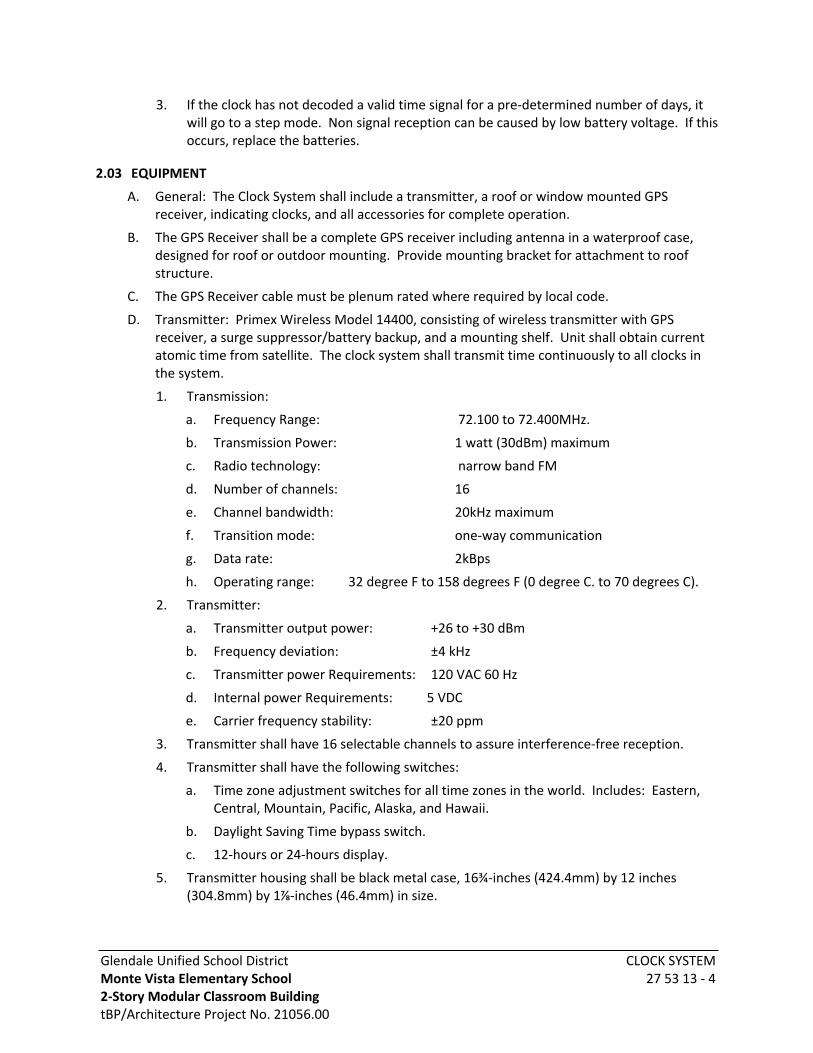
Glendale Unified School DistrictMonte Vista Elementary School2-Story Modular Classroom BuildingtBP/Architecture Project No. 21056.00
CLOCK SYSTEM27 53 13 - 4
3. If the clock has not decoded a valid time signal for a pre-determined number of days, it will go to a step mode. Non signal reception can be caused by low battery voltage. If this occurs, replace the batteries.
2.03 EQUIPMENT
A. General: The Clock System shall include a transmitter, a roof or window mounted GPS receiver, indicating clocks, and all accessories for complete operation.
B. The GPS Receiver shall be a complete GPS receiver including antenna in a waterproof case, designed for roof or outdoor mounting. Provide mounting bracket for attachment to roof structure.
C. The GPS Receiver cable must be plenum rated where required by local code.
D. Transmitter: Primex Wireless Model 14400, consisting of wireless transmitter with GPS receiver, a surge suppressor/battery backup, and a mounting shelf. Unit shall obtain current atomic time from satellite. The clock system shall transmit time continuously to all clocks in the system.
1. Transmission:
a. Frequency Range: 72.100 to 72.400MHz.
b. Transmission Power: 1 watt (30dBm) maximum
c. Radio technology: narrow band FM
d. Number of channels: 16
e. Channel bandwidth: 20kHz maximum
f. Transition mode: one-way communication
g. Data rate: 2kBps
h. Operating range: 32 degree F to 158 degrees F (0 degree C. to 70 degrees C).
2. Transmitter:
a. Transmitter output power: +26 to +30 dBm
b. Frequency deviation: ±4 kHz
c. Transmitter power Requirements: 120 VAC 60 Hz
d. Internal power Requirements: 5 VDC
e. Carrier frequency stability: ±20 ppm
3. Transmitter shall have 16 selectable channels to assure interference-free reception.
4. Transmitter shall have the following switches:
a. Time zone adjustment switches for all time zones in the world. Includes: Eastern, Central, Mountain, Pacific, Alaska, and Hawaii.
b. Daylight Saving Time bypass switch.
c. 12-hours or 24-hours display.
5. Transmitter housing shall be black metal case, 16¾-inches (424.4mm) by 12 inches (304.8mm) by 1⅞-inches (46.4mm) in size.

Glendale Unified School DistrictMonte Vista Elementary School2-Story Modular Classroom BuildingtBP/Architecture Project No. 21056.00
CLOCK SYSTEM27 53 13 - 5
6. Antenna shall be 46-inches (1168mm) high, commercial type, mounted on top center of transmitter housing. Antenna gain shall be < 2.2dB. Antenna polarization shall be vertical.
7. Transmitter housing shall incorporate a display which shall include the following:
a. Time readout
b. AM and PM indicator if 12-hour time display is set
c. Day and date readout
d. Indicator for daylight savings or standard time
e. LED which shall flash red in event of reception problem
f. GPS reception indicator
8. Transmitter shall contain an internal clock such that failure of reception from the GPS will not disable the operation of the clocks.
9. Power supply (included):
Input: 120-volt AC 50/60Hz, 0.4 amps.Output: 9-volt DC, 1.5 amps.
E. Surge Protector/Battery Backup (included).
Input: 120-volt AC 60 Hz ±1Hz.Output: 120-volt AC, 500VA, 300 wattsSurge Energy Rating: 365 joules
F. Additional Equipment
1. Wireless Receiver Switches: Switches shall receive time packets from the Primary Transmitter and relay the synchronized time to the Satellite Transmitter connected to it. The unit shall include the following:
a. Antenna mounted on top of the switch housing, 11½-inches (292mm) long. Power Supply:· Input 120 VAC 50/60Hz, 0.4 amps · Output: 9-volt DC, 1.5 amps RS 232 data cable, 5 feet (1.5mm) long
b. Daylight Savings Time bypass switch
c. Dimensions: 4¼-inches (108mm) long, 5¾-inches (146mm) wide, 1¼-inches (31.75mm) deep.
d. Weight: 12 ounces (.34kg)
e. Operating Range: 32 degrees F to 158 degrees F (0 to 70 degrees C)
2. Satellite Transmitters Primex Wireless Model 14401: Satellite Transmitters shall receive the signal from the Wireless Receiver Switches and transmit the signal to the devices in its vicinity, which are out of the range from the Master Transmitter. The unit shall include the following:
a. Antenna mounted on top of the housing, 46 inches (1168mm) long.
b. Wireless Receiver Switch.
c. Power Supply Input: 120

Glendale Unified School DistrictMonte Vista Elementary School2-Story Modular Classroom BuildingtBP/Architecture Project No. 21056.00
CLOCK SYSTEM27 53 13 - 6
d. VAC, 50/60Hz, 0.4 amps
e. Output: 9-volt DC, 1.5 amps.
f. 6-foot (1.83m) cord
g. Surge Suppressor/Battery Backup
h. Mounting Shelf.
i. Transmission Power: 1 watt maximum
j. 72 MHz frequency.
3. Traditional analog clocks (battery): Analog clocks shall be wall mounted. Clocks shall have polycarbonate frame and polycarbonate lens. Face shall be white. Hour and minute hands shall be black.
a. 9 inches (228.6mm) diameter analog clock: Primex Wireless Model 14280
b. 12½-inch (317.5mm) diameter analog clock: Primex Wireless Model 14155
c. 16 inches (406.4mm) diameter analog clock: Primex Wireless Model 14163
d. 24 inches (610mm) diameter analog clock: Primex Wireless Model 14346
4. Additional colors, finishes, and dial faces are available from Manufacturer.
a. Analog clocks shall be battery-operated,
b. Analog clocks shall be capable of automatically adjusting for Daylight Saving Time. An on-off switch located on the transmitter shall disable this function If desired.
c. Time shall be automatically updated from the transmitter 6 times per day.
d. Analog clocks shall remember the time during changing of batteries.
e. 9 inches (228.6mm) and 12.5 inches (317.5mm) analog clocks shall have a tamper proof/theft resistant clock lock mounting slots.
5. Analog clock receivers shall be as follows:
a. Receiver sensitivity: >-110 dBm
b. Receiver power: 24 VAC or 120VAC (see model #)
c. Antenna type: internal
d. Antenna gain: -7dBd
If transmitter stops transmitting valid time signals due to power failure, the clocks will continue to function as accurate quartz clocks until a valid time signal is decoded. If signal transmission is not restored after 96 hours, the second hand will “five-step” as a visual indicator that the signal has been lost. Should the clocks lose power and signal, the clocks will not function.
6. Wire guards: Provide one for each analog clock as follows:
a. Analog clock wire guard Primex Wireless Model 14131, 14-inches by 14-inches (355.6 by 355.6 mm) size, for nominal 12½-inch (317.5 mm) diameter analog clocks.
b. Analog clock wire guard Primex Wireless Model 14123, 18-inches by 18-inches (457.2 by 457.2mm) size, for 16 inches (406.4mm) diameter analog clocks.
7. Cable Connection Sealant: Radio Shack Coaxial Cable Connector Sealant 278-1645 or approved electrical grade silicone sealant.
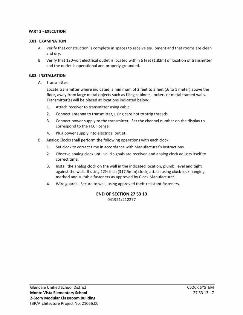
Glendale Unified School DistrictMonte Vista Elementary School2-Story Modular Classroom BuildingtBP/Architecture Project No. 21056.00
CLOCK SYSTEM27 53 13 - 7
PART 3 - EXECUTION
3.01 EXAMINATION
A. Verify that construction is complete in spaces to receive equipment and that rooms are clean and dry.
B. Verify that 120-volt electrical outlet is located within 6 feet (1.83m) of location of transmitter and the outlet is operational and properly grounded.
3.02 INSTALLATION
A. Transmitter:
Locate transmitter where indicated, a minimum of 2 feet to 3 feet (.6 to 1 meter) above the floor, away from large metal objects such as filing cabinets, lockers or metal framed walls. Transmitter(s) will be placed at locations indicated below:
1. Attach receiver to transmitter using cable.
2. Connect antenna to transmitter, using care not to strip threads.
3. Connect power supply to the transmitter. Set the channel number on the display to correspond to the FCC license.
4. Plug power supply into electrical outlet.
B. Analog Clocks shall perform the following operations with each clock:
1. Set clock to correct time in accordance with Manufacturer's instructions.
2. Observe analog clock until valid signals are received and analog clock adjusts itself to correct time.
3. Install the analog clock on the wall in the indicated location, plumb, level and tight against the wall. If using 12½-inch (317.5mm) clock, attach using clock-lock hanging method and suitable fasteners as approved by Clock Manufacturer.
4. Wire guards: Secure to wall, using approved theft-resistant fasteners.
END OF SECTION 27 53 13041921/212277

Glendale Unified School District INTRUSION DETECTION SYSTEMMonte Vista Elementary School 2-Story Modular Classroom Building 28 31 00 - 1tBP/Architecture Project No. 21056.00
SECTION 28 31 00INTRUSION DETECTION SYSTEM
PART 1 - GENERAL
1.01 SCOPE
A. Work Included: All labor, materials, appliances, tools, equipment necessary for and incidental to performing all operations in connection with furnishing, delivery and installation of the work of this Section, complete, as shown on the Drawings and/or specified herein. Work includes, but is not necessarily limited to the following:
1. Examine all other Specifications Sections and Drawings for related work required to be included as work under Division 26, 27, and 28.
2. General Provisions and Requirements for electrical work.
1.02 QUALIFICATION OF BIDDERS AND EQUIPMENT
A. To qualify as an acceptable Bidder, whether the bid is submitted to the District, his Agent, a General Contractor or a Sub-Contractor, the System Bidder or Contractor shall be qualified Contractor and shall hold a valid License issued by the State of California Department of Consumer Affairs Collection and Investigation Services for the purpose of installing security systems. The System Bidder or Contractor shall hereinafter be referred to as the Contractor. The Contractor shall hold all other licenses required by the legally constituted authorities having jurisdiction over the work. The Contractor shall be the factory authorized Distributor for the branch of equipment offered and shall have been engaged in the business of supplying and installing the specified type of system for at least 5-years. The Contractor shall maintain a fully equipped service organization capable of furnishing adequate repair service to the equipment. The Contractor shall be financially able to provide a performance bond covering the work and the guarantee described. The Contractor shall provide that bond if requested.
B. The equipment specified herein shall be DSC Power Series Pro from Tyco security product. Call DSC at 1-800-387-3630 for a list local factory authorized Supplier.
C. The system shall be serviced by a field supported 2-year warranty.
D. The Specification is based on the equipment of Manufacturers who have been approved by the District and the Manufacturers herein named shall be considered as meeting the Requirements of this Specification. For all items which are identified by part number and Manufacturer the Performance Specifications which are published in the most recent Manufacturers data sheets available at the time of bidding this project shall be applicable to the present work as though fully written out herein.
E. All equipment shall conform to all local applicable Codes and Ordinances and shall be listed by Underwriters Laboratories.
F. Installation Certification
1. Work and material for cables, cable terminations and related components shall be performed by certified Installers. The Installer shall be certified by the respective Product Manufacturers.
2. The Manufacturers of the indicated work and material shall provide an Installer education/training and certification program for the supplied products.

Glendale Unified School District INTRUSION DETECTION SYSTEMMonte Vista Elementary School 2-Story Modular Classroom Building 28 31 00 - 2tBP/Architecture Project No. 21056.00
3. The Installers performing the Contract Work for the indicated products, shall have attended, and successfully completed each of the respective Manufacturer's installation training education programs for the specified products.
4. Submit six copies of the Manufacturer's certifications for each Installer performing the work. The submittal shall be approved prior to initiating any related Contract Work.
5. Contract material installed, and work performed by Installers not complying with these Requirements shall be removed. Removal of work and material not in compliance with these Requirements shall done at the Contractor's expense, without any additional cost to the Contract and without any Additional Contract completion due date extensions. New material and work required to replace the non-compiling removed work and material shall be provided at the Contractor's expense, without any additional cost to the Contract and without any Additional Contract completion due date extensions.
1.03 PERFORMANCE REQUIREMENTS
A. Provide main control panel, terminal cabinets with manufacture key lock, keypads, and site underground conduits as indicated.
B. Provide a Dual technology PIR/Microwave 360° motion sensor(s) in each room having exterior doors, exterior glass, or skylights. Quantity of sensors in each room shall be as required to detect entry through exterior doors, exterior glass, or skylights.
1. Motion detector should be installed center of room and sensitivity of microwave detection should be reduce to appropriate level for the room size which it is located and installed in according to Manufacture Specification.
C. Provide a magnetic switch at the entry door to each building, near its respective keypad. Connect to the system to initiate a timing circuit for keypad operation.
D. Provide magnetic switches at roof hatches.
E. Provide all conduits, cabling, and outlet boxes required for a complete and operable system.
F. Install all DSC LCD Keypads model HS2LCDPRO(RF)(P) in each exterior common area for each building to allow instructors disarming access at each building.
1. Keypads shall be installed in a solid white polycarb enclosure and exterior thumb lock with “F” back-box Model number: STI-7511F-OW
1.04 SUBMITTALS (ADDITIONAL REQUIREMENTS)
A. Submit evidence of having met with District Representatives as specified herein.
B. Submit product data sheets for all switches, keypads, wiring devices, device plates, controllers, power supplies, cabinets, etc.
C. Submit detailed Shop Diagrams including dimensioned plans, elevations, details, schematic and point-to-point wiring diagrams and descriptive literature for all component parts and cabinets.
D. Submit six copies redrawn Building Floor Plans showing all components of the intrusion detection system including interconnecting cabling and conduits. Sensors shall be located on the Drawings in the location conforming to the Requirements stated herein. Drawings shall be prepared to scale and show all exterior glass, exterior doors, all interior and exterior building walls, roof hatches, architectural and structural elements relevant to the installation of the
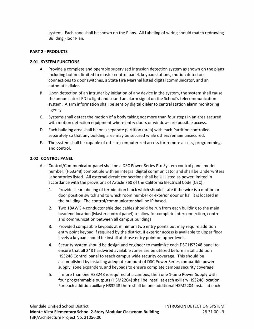
Glendale Unified School District INTRUSION DETECTION SYSTEMMonte Vista Elementary School 2-Story Modular Classroom Building 28 31 00 - 3tBP/Architecture Project No. 21056.00
system. Each zone shall be shown on the Plans. All Labeling of wiring should match redrawing Building Floor Plan.
PART 2 - PRODUCTS
2.01 SYSTEM FUNCTIONS
A. Provide a complete and operable supervised intrusion detection system as shown on the plans including but not limited to master control panel, keypad stations, motion detectors, connections to door switches, a State Fire Marshal listed digital communicator, and an automatic dialer.
B. Upon detection of an intruder by initiation of any device in the system, the system shall cause the annunciator LED to light and sound an alarm signal on the School's telecommunication system. Alarm information shall be sent by digital dialer to central station alarm monitoring agency.
C. Systems shall detect the motion of a body taking not more than four steps in an area secured with motion detection equipment where entry doors or windows are possible access.
D. Each building area shall be on a separate partition (area) with each Partition controlled separately so that any building area may be secured while others remain unsecured.
E. The system shall be capable of off-site computerized access for remote access, programming, and control.
2.02 CONTROL PANEL
A. Control/Communicator panel shall be a DSC Power Series Pro System control panel model number: (HS3248) compatible with an integral digital communicator and shall be Underwriters Laboratories listed. All external circuit connections shall be UL listed as power limited in accordance with the provisions of Article 760 of the California Electrical Code (CEC).
1. Provide clear labeling of termination block which should state if the wire is a motion or door position switch and to which room number or exterior door or hall it is located in the building. The control/communicator shall be IP based.
2. Two 18AWG 4 conductor shielded cables should be run from each building to the main headend location (Master control panel) to allow for complete interconnection, control and communication between all campus buildings
3. Provided compatible keypads at minimum two entry points but may require addition entry point keypad if required by the district, if exterior access is available to upper floor levels a keypad should be install at those entry point on upper levels.
4. Security system should be design and engineer to maximize each DSC HS3248 panel to ensure that all 248 hardwired available zones are be utilized before install addition HS3248 Control panel to reach campus wide security coverage. This should be accomplished by installing adequate amount of DSC Power Series compatible power supply, zone expanders, and keypads to ensure complete campus security coverage.
5. If more than one HS3248 is required at a campus, then one 1-amp Power Supply with four programmable outputs (HSM2204) shall be install at each axillary HS3248 location. For each addition axillary HS3248 there shall be one additional HSM2204 install at each

Glendale Unified School District INTRUSION DETECTION SYSTEMMonte Vista Elementary School 2-Story Modular Classroom Building 28 31 00 - 4tBP/Architecture Project No. 21056.00
Axillary HS3248 location. For each additional Axillary HS3248 install there shall be an additional HSM2204 installed at the Headend at the Master Control Panel (Main HS3248)
a. Example*: if there are total of Three Axillary HS3248 install on a campus there will be three HSM2204 install at the Main headend HS3248 control panel and one at each axillary control panel location for a total of six HSM2204 campus wide to allow interconnection control between main head end and all axillary control panels.
B. System shall include the following features:
1. Real time clock and test timer.
2. Battery charging circuit.
3. Battery voltage supervision.
4. Supervised automatic reset circuit breakers.
5. Onboard warning buzzer and diagnostic LEOs.
6. Automatic answer modem.
7. Lightning and RFI protection.
8. Central Station reporting format.
9. Printer/CRT interface module for on-site serial data printer recording or CRT display of events.
10. Quad serial output module for enhanced serial data interface capability for specific accessory modules and devices.
11. Individual zone responses.
12. Custom annunciator text.
13. Audible alarm output, steady or pulsed.
14. Automatic silencing.
15. Attack-Resistant enclosure and lock meeting Underwriters Laboratory Local Burglary Requirements.
16. A minimum of eight auxiliary form "C" dry contacts for a variety of programmable responses to alarm and trouble conditions.
17. Transformer enclosure for internal mounting of Class 2 transformer.
18. Two telephone numbers with selective signaling options.
19. Individual zone responses.
20. Automatic test reports.
2.03 BAR-CODE
Bar-code programmer for diagnostics and programming capability
2.04 RECEIVER
A. Receiver shall be DSC Power PRO Series, UL listed for fire and intrusion detection.
B. 18 VDC Power Adapter for main panel and power supplies Model: HS65WPSNA
C. System shall contain 48 hours of standby power utilizing rechargeable sealed lead acid batteries and a battery charger.

Glendale Unified School District INTRUSION DETECTION SYSTEMMonte Vista Elementary School 2-Story Modular Classroom Building 28 31 00 - 5tBP/Architecture Project No. 21056.00
D. System shall be FCC approved for telephone connections.
E. An alphanumeric LCD display shall indicate account number, area number, time, date, event, zone or point number, line or group number, status, and external devices.
F. 24-hour clock and 128-year calendar.
G. Forty-character line internal printer and interface capability with an external serial printer.
H. Transmission verification appropriate with the format utilized.
I. Storage of 249 separate events.
J. Transmission format shall support the control panel.
K. Turn the receiver over to the District for central station or campus monitoring.
2.05 REMOTE ACCOUNT MANAGER
A. System shall be DSC Power PRO Series or equal with all equipment necessary for computerized access, programming, diagnostics, and remote control of the system. It shall be possible to remotely change passcodes, locate faults, shunt problem zones, arm and disarm the system, silence alarms, and control the auxiliary output contacts in the control panel.
B. System shall permit remote diagnostics including utility and battery power conditions, phone line condition, event memory by zone, and current clock and calendar settings.
C. System shall be 100% IBM compatible for use with personal computers.
D. System shall include a plug-in modem and software necessary for a complete and operable installation. Furnish the District with a software license agreement for updated software enhancements as they develop.
2.06 KEYPADS
A. Install all DSC LCD Keypads model HS2LCDPRO(RF)(P) in each exterior common area for each building to allow instructors disarming access at each building.
1. Keypads shall be installed in a solid white polycarb enclosure and exterior thumb lock with “F” back-box Model number: STI-7511F-OW
2.07 MOTION SENSORS
A. Provide a Dual technology PIR/Microwave 360° motion sensor(s) in each room having exterior doors, exterior glass, or skylights. Quantity of sensors in each room shall be as required to detect entry through exterior doors, exterior glass, or skylights.
1. Motion detector should be installed center of room and sensitivity of microwave detection should be reduce to appropriate level for the room size which it is located and installed in according to manufacture specification.
2. Sensor coverage patterns shall be as required for optimum coverage at each individual location. Sensor shall be adjustable Gimbal mounted with plate and outlet box. Provide an attack resistant enclosure DS AE774 at Multipurpose areas. Shall have a DSC expansion cabinet with sufficient amount of 2-amp Power supply bus extenders with four relays output model: HSM3204CX and eight zone expanders model: 3408 to supervise and power the cross connects from the field wire termination cabinet.
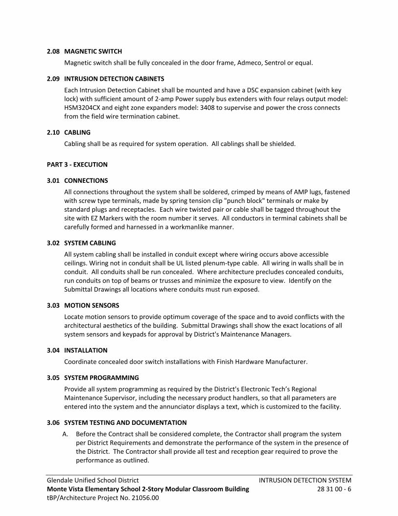
Glendale Unified School District INTRUSION DETECTION SYSTEMMonte Vista Elementary School 2-Story Modular Classroom Building 28 31 00 - 6tBP/Architecture Project No. 21056.00
2.08 MAGNETIC SWITCH
Magnetic switch shall be fully concealed in the door frame, Admeco, Sentrol or equal.
2.09 INTRUSION DETECTION CABINETS
Each Intrusion Detection Cabinet shall be mounted and have a DSC expansion cabinet (with key lock) with sufficient amount of 2-amp Power supply bus extenders with four relays output model: HSM3204CX and eight zone expanders model: 3408 to supervise and power the cross connects from the field wire termination cabinet.
2.10 CABLING
Cabling shall be as required for system operation. All cablings shall be shielded.
PART 3 - EXECUTION
3.01 CONNECTIONS
All connections throughout the system shall be soldered, crimped by means of AMP lugs, fastened with screw type terminals, made by spring tension clip "punch block" terminals or make by standard plugs and receptacles. Each wire twisted pair or cable shall be tagged throughout the site with EZ Markers with the room number it serves. All conductors in terminal cabinets shall be carefully formed and harnessed in a workmanlike manner.
3.02 SYSTEM CABLING
All system cabling shall be installed in conduit except where wiring occurs above accessible ceilings. Wiring not in conduit shall be UL listed plenum-type cable. All wiring in walls shall be in conduit. All conduits shall be run concealed. Where architecture precludes concealed conduits, run conduits on top of beams or trusses and minimize the exposure to view. Identify on the Submittal Drawings all locations where conduits must run exposed.
3.03 MOTION SENSORS
Locate motion sensors to provide optimum coverage of the space and to avoid conflicts with the architectural aesthetics of the building. Submittal Drawings shall show the exact locations of all system sensors and keypads for approval by District's Maintenance Managers.
3.04 INSTALLATION
Coordinate concealed door switch installations with Finish Hardware Manufacturer.
3.05 SYSTEM PROGRAMMING
Provide all system programming as required by the District's Electronic Tech’s Regional Maintenance Supervisor, including the necessary product handlers, so that all parameters are entered into the system and the annunciator displays a text, which is customized to the facility.
3.06 SYSTEM TESTING AND DOCUMENTATION
A. Before the Contract shall be considered complete, the Contractor shall program the system per District Requirements and demonstrate the performance of the system in the presence of the District. The Contractor shall provide all test and reception gear required to prove the performance as outlined.
Glendale Unified School District INTRUSION DETECTION SYSTEMMonte Vista Elementary School 2-Story Modular Classroom Building 28 31 00 - 7tBP/Architecture Project No. 21056.00
B. Actuate motion sensing devices and verify that the system performs as specified.
C. The communication loops shall be opened in at least two locations per building to check for the presence of correct supervisory circuitry.
D. When the testing has been completed to the satisfaction of both Contractor's Job Foreman and the Representatives of the Manufacturer and the DSA Inspector, a notarized letter co-signed by each attesting to the satisfactory completion of said testing shall be provided by the Contractor and forwarded to the Architect.
3.07 TRAINING
Provide a minimum of two 4-hour periods to instruct District Personnel in proper operation of all systems. Instruction to be arranged in advance at the District’s convenience and conducted during normal working hours from 6:30 a.m. to 3:00 p.m. Monday through Friday. Instructors and participants shall sign an attendance sheet of which a copy is to be given to the District Authorized Representative during closeout documentation. The first instructional period shall be held prior to final acceptance of the systems. Instructional training shall be done at the project site and shall be conducted by factory-trained Technical Personnel. Furnish the District with an electronic audio/ visual recording of the first instruction session on a DVD. The second instructional period shall be within a period of 1-year after final acceptance of the systems, upon request of the District, during normal working hours 6:30 a.m. to 3:00 p.m., Monday through Friday.
END OF SECTION 28 31 00041921/212277

Glendale Unified School DistrictMonte Vista Elementary School 2-Story Modular Classroom BuildingtBP/Architecture Project No. 21056.00
FIRE DETECTION AND ALARM28 46 20 - 1
SECTION 28 46 20FIRE DETECTION AND ALARM
PART 1 - GENERAL
1.01 SCOPE
A. Work Included: All labor, materials, appliances, tools, equipment necessary for and incidental to performing all operations in connection with furnishing, delivery, and installation of the work of this Section, complete, as shown on the Drawings and/or specified herein. Work includes, but is not necessarily limited to the following:
1. Examine all other Specifications Sections and Drawings for related work required to be included as work under Division 26, 27, and 28.
2. General Provisions and Requirements for electrical work.
B. This Specification provides the Minimum Requirements for the Fire Alarm and Detection System. The system shall include, but not limited to all equipment, materials, labor, documentation, and services necessary to furnish and install a complete, operational system to include but not limited to the following functions:
1. Smoke and fire detection.
2. Sprinkler suppression system monitoring and control.
3. Off-premises notification.
4. Door release.
5. Mass Notification system.
6. One-way voice communication notification system.
7. Two-way voice communication system.
1.02 SUBMITTALS (ADDITIONAL REQUIREMENTS)
A. Submit eight copies of the following to the Architect for approval.
1. A listing of all fire alarm components and equipment including the California State Fire Marshal (CSFM) listing numbers.
2. CSFM listing sheets of all devices being used.
3. Manufacturers’ standard catalog data for fire alarm components.
a. The submittal shall be arranged in the order of the Specification and shall list the Specification paragraph number, the name, the proposed model, and Manufacturer for each item as well as a reference indicating the specific piece of data which can be easily located in the brochure.
b. The Manufacturers’ data sheets shall be marked to indicate the specific item being proposed in cases where the sheet covers several types or sizes of item. The data sheet shall completely describe the proposed item.
c. Where modification to the equipment is necessary to meet the Operational Requirements of the Contract Documents and the data sheets shall include complete Mechanical and Electrical Shop Drawings detailing the modification.
Glendale Unified School DistrictMonte Vista Elementary School 2-Story Modular Classroom BuildingtBP/Architecture Project No. 21056.00
FIRE DETECTION AND ALARM28 46 20 - 2
4. A listing of the outlet rough-in needed for every device and equipment item. The applicable symbol which illustrates that rough-in item on the job plans shall be drawn on the proposal, opposite the description of the rough-in to facilitate locating the data by Field Personnel.
5. Elevation and dimensional information.
1.03 APPLICABLE CODES AND STANDARDS
A. The Fire Alarm System shall comply with the currently adopted versions of the following:
1. Building Standards Administrative Code, Part 1, Title 24, California Code of Regulations.
2. California Building Code (CBC) Part 2, Title 24, California Code of Regulations (International Building Code, with California Amendments).
3. California Electrical Code (CEC) Part 3, Title 24, California Code of Regulations (National Electrical Code with California Amendments).
4. California Mechanical Code (CFC) Part 4, Title 24, California Code of Regulations (Uniform Mechanical Code with California Amendments).
5. California Fire Code (CFC) Part 9, Title 24, California Code of Regulations (International Fire Code with California Amendments).
B. NFPA Standards
1. The fire alarm system shall comply with the applicable provisions of the following current National Fire Protection Association (NFPA) Standards:
a. NFPA 12 Carbon Dioxide Extinguishing Systems
b. NFPA 12A Halon 1301 Fire Extinguishing Systems
c. NFPA 13 Installation of Sprinkler Systems
d. NFPA 15 Water Spray Fixed Systems
e. NFPA 16 Foam-Water Sprinkler Systems
f. NFPA 17 Dry Chemical Extinguishing Systems
g. NFPA 17A Wet Chemical Extinguishing Systems
h. NFPA 72, National Fire Alarm and Signaling Code:
1) Central Station Fire Alarm Systems
2) Local Fire Alarm Systems
3) Auxiliary Fire Alarm Systems
4) Remote Station Fire Alarm Systems
5) Proprietary Fire Alarm Systems
i. NFPA 90A, Installation of Air Conditioning and Ventilating Systems
j. NFPA 101, Life Safety Code - Safety to Life from Fire in Buildings and Structures
k. NFPA 750 Water Mist Fire Protection Systems
l. NFPA 2001 Clean Agent Fire Extinguishing Systems
2019 Building Standards Administration Code, Part 1, Title 24, California Code of Regulations.2019 California Building Code (CBC) Part 2, Title 24, California Code of Regulations
2019 California Electrical Code (CEC) Part 3, Title 24, California Code of Regulations (National
2019 California Mechanical Code (CFC) Part 4, Title 24, California Code of Regulations (Uniform
2019 California Fire Code (CFC) Part 9, Title 24, California Code of Regulations (International
(2018 Edition)
(2018 Edition)(2016 Edition)
(2019 Edition)
(2016 Edition)(2017 Edition)
(2017 Edition)(2016 Edition)
(2018 Edition)(2018 Edition)
(2019 Edition)(2018 Edition)
Glendale Unified School DistrictMonte Vista Elementary School 2-Story Modular Classroom BuildingtBP/Architecture Project No. 21056.00
FIRE DETECTION AND ALARM28 46 20 - 3
C. ADA – Americans with Disabilities Act
D. CAC – California Administrative Code, Title 24
E. UL Standards
1. The system shall comply with the applicable provisions of the following UL Standards and Classifications:
a. UL 38, Manual Signaling Boxes for Fire Alarm Systems
b. UL 268, Smoke Detectors for Fire Alarm Systems
c. UL 268A, Smoke Detectors for Duct Applications
d. UL 346, Water flow Indicators for Fire Protective Signaling Systems
e. UL 464, Audible Signal Appliances
f. UL 521, Heat Detectors for Fire Protective Signaling Systems
g. UL 864, Control Units and Accessories for Fire Alarm Systems
h. UL 1480, Speakers for Fire Alarm Use
i. UL 1481, Power Supplies for Fire Protective Signaling Systems
j. UL 1635, Digital Alarm Communicator System Units
k. UL 1638, Visual Signaling Appliances
l. UL 1971, Signaling Devices for the Hearing Impaired
m. UOJZ, Control Units, System
n. SYZV, Control Units, Releasing Device
o. UOXX, Control Unit Accessories, System
p. SYSW, Accessories, Releasing Device Service
1.04 EQUIPMENT AND INSTALLING QUALIFICATIONS
A. The Equipment shall be manufactured by Notifier or approved equal.
B. The Specification is based on the equipment of Manufacturers who have been approved by the District and the Manufacturers herein named shall be considered as meeting the Requirements of this Specification. For all items which are identified by part number and Manufacturer the Performance Specifications which are published in the most recent Manufacturer’s data sheets available at the time of bidding this project shall be applicable to the present work as though fully written out herein.
C. All Equipment shall conform to all local applicable Codes and Ordinances and shall be listed by Underwriters Laboratories.
D. To Qualify as an acceptable Bidder, whether the bid is submitted to the District, his Agent, a General Contractor or a Sub-Contractor, the System Bidder or Contractor shall be qualified Fire Alarm Contractor and shall hold a valid C10 License issued by the Contractors State License Board of California. The System Bidder or Contractor shall hereinafter be referred to as the Contractor. The Contractor shall hold all other licenses required by the legally constituted Authorities Having Jurisdiction over the work. The Contractor shall be the Factory Authorized Distributor for the branch of equipment offered and shall have been engaged in the business of supplying and installing the specified type of system for at least 5-years. The

Glendale Unified School DistrictMonte Vista Elementary School 2-Story Modular Classroom BuildingtBP/Architecture Project No. 21056.00
FIRE DETECTION AND ALARM28 46 20 - 4
Contractor shall maintain a fully equipped service organization capable of furnishing adequate repair service to the equipment. The Contractor shall be financially able to provide a performance bond covering the work and the guarantee described. The Contractor shall provide that bond if requested.
E. Installation Certification
1. Work and material for cables, cable terminations and related components shall be performed by certified Installers. The installer shall be certified by the respective Product Manufacturers.
2. The Manufacturers of the indicated work and material shall provide an Installer education/training and certification program for the supplied products.
3. The Installers performing the Contract work for the indicated products shall have attended and successfully completed each of the respective Manufacturer's installation training education programs for the specified products.
4. Submit six copies of the Manufacturer's certifications for each Installer performing the work. The submittal shall be approved prior to initiating any related Contract Work.
5. Contract material installed, and work performed by Installers not complying with these Requirements shall be removed. Removal of work and material not in compliance with these Requirements shall done at the Contractors’ expense, without any additional cost to the Contract and without any additional Contract completion due date extensions. New material and work required to replace the non-compiling removed work and material shall be provided at the Contractors’ expense, without any additional cost to the Contract and without any additional Contract completion due date extensions.
PART 2 - PRODUCTS
2.01 GENERAL SYSTEM OPERATION
A. System shall be microprocessor-based, addressable, and power-limited with Class B supervised circuits, one-way and two-way emergency audio communications.
1. The microprocessor shall execute all supervisory and control programming to detect, report the failure or disconnection of any system module or peripheral device and initiate programmed control sequences. An isolated supervision "watchdog" circuit shall monitor the microprocessor and, upon failure, shall activate the system trouble circuits.
2. The automatic fire detection and alarm system shall consist of main control panel, transponder panel(s), notification alarm devices, remote annunciator, automatic detection devices, manual stations, printer, and CRT/keyboard, installed and wired in accordance with the Drawings and shall function as specified herein.
3. The system shall be programmable in the field, by a non-computer trained person. All programmed information shall be stored in non-volatile memory.
4. The system shall operate both addressable and non-addressable ionization, thermal and photoelectric detecting devices, manual stations, water-flow switches, and external control modules.
Glendale Unified School DistrictMonte Vista Elementary School 2-Story Modular Classroom BuildingtBP/Architecture Project No. 21056.00
FIRE DETECTION AND ALARM28 46 20 - 5
5. The control panel shall provide power, annunciation, supervision and control for the fire detection and alarm system. The system shall be designed such that alarm indications override trouble and control conditions.
6. External circuit supervision shall not require additional wires other than the pair used for detection or alarm (only two wires shall be used from the control panel to each loop of initiating devices and two wires for the notification alarm devices). These two wires shall provide both supervision and notification alarm signals. There shall be no loss of super-vision for Class "B" wired addressable devices. Class "A" supervision may be provided by adding an additional pair of wires.
B. Alarm Conditions
1. Actuation of any manual or automatic alarm initiating device, connected to the system shall cause the following automatic functions.
a. All notification alarm signaling units shall activate continuously. Audible notification alarms shall sound the California State Coded Signal.
b. The respective zone alarm lamp or annunciator alphanumeric readout on the central control panel, and remote annunciator panel, shall be activated.
c. Activate the Digital Alarm Communicator system.
2. Actuation of HVAC air duct smoke detectors shall stop the designated fans and motors in the building's air distribution system.
3. Actuation of smoke detectors on either side of smoke doors shall energize the release mechanism on the smoke door causing the door to close.
4. Notification alarm signal duration shall be capable of continuous sounding or adjustable from three to 10-minutes.
5. Perform any additional functions as specified herein or shown on the Drawings.
C. Trouble Condition
1. A single open or single trouble condition in a manual or automatic fire initiating wiring circuit shall activate the respective zone trouble lamp or annunciator readout on the fire alarm control panel and sound a trouble signal at the control panel.
2. A single open or single trouble condition in the notification alarm signaling wiring circuit shall activate the trouble lamp or annunciator readout in the control panel and sound a trouble signal at the control panel.
3. 120-volt AC normal power shall be monitored with indication by a "power on" lamp. Upon normal power outage, the system shall activate power trouble condition lamp or annunciator readout and indicate a trouble condition.
4. The control panel shall monitor the standby batteries and, upon a low battery condition, activate the low battery lamp or annunciator readout and indicate a trouble condition.
5. System ground detection shall be provided for the entire system. Upon ground detection, activate the ground detection lamp or annunciator readout and indicate a trouble condition.
D. Control Panels employing alphanumeric readouts shall display the trouble condition along with a prompt to review the list chronologically. The end of the list shall be indicated.

Glendale Unified School DistrictMonte Vista Elementary School 2-Story Modular Classroom BuildingtBP/Architecture Project No. 21056.00
FIRE DETECTION AND ALARM28 46 20 - 6
2.02 FIRE ALARM CONTROL PANEL
A. General
1. The fire alarm control panel shall be software programmable, microprocessor controlled, solid state, electronic integrated system. The panel shall be the product of one Manufacturer. The control panel shall provide power, annunciation, supervision and control for the detection and alarm system. The detection system shall remain 100% operational, responding to an alarm condition while in the routine maintenance mode.
2. Addressable detection and control devices shall be individually identified by the system, and any quantity of addressable detection devices shall be in alarm and any quantity of addressable control units shall be operable at any time up to the total number connected to the system.
3. The microprocessor shall access the system program, which is stored in non-volatile programmable memory, for all control-by-event (CBE) functions. The system program shall not be lost upon failure of both primary and secondary power. Volatile memory shall not be acceptable.
4. A means shall be provided for acknowledging each abnormal condition. Each activation of the appropriate acknowledge button shall sequentially acknowledge every point in the system. After all the points have been acknowledged, the LEDs shall glow steady and the panel audible signal will be silenced. The total number of alarms, supervisory, and trouble conditions shall be displayed along with a prompt to review each list chronologically. The end of the list shall be so indicated.
5. An alphanumeric annunciator readout shall indicate on the control panel the activation by type, loop, and address of the specific device, sub-loop or alarm/monitor/control points via an alphanumeric display. An audible alert shall sound at the control panel and an alarm light shall flash.
6. If the microprocessor fails, the system shall executive a default signaling program. This program shall enable the control panel to sound the audible signals and summon the Fire Department. In addition, a red LED shall light to indicate the communication loop wherein the alarm originated. Inability of the system to sound signals or summon the Fire Department during microprocessor failure shall not be acceptable.
7. Protected access to the system controls shall be provided to allow the user/operator access to the following system functions:
a. Status of all addressable points.
b. Status of all events logged.
c. Set/change the real-time clock and date.
d. Perform an operational manual test of the system from the control panel, including actuation of any initiating device and trouble circuit without alarming the remote central station. The panel shall automatically return to normal mode in the event the panel remains unattended in the service mode.
e. Retrieve from event log the last 300 alarms, or control points and 300 trouble conditions.
Glendale Unified School DistrictMonte Vista Elementary School 2-Story Modular Classroom BuildingtBP/Architecture Project No. 21056.00
FIRE DETECTION AND ALARM28 46 20 - 7
8. Individual input (monitor) and output (control) device addressability shall all be performed on the same pair of wires. Wiring shall be Class "A" or "B". When Class "B" wiring is used, no special wiring sequence shall be required on addressable device circuits. An unlimited number of wiring branches shall be permitted with no loss of supervision.
9. A minimum of 25% addressable monitor, trouble and control points shall be provided.
B. Cabinet
1. A metal tamper resistant cabinet shall contain the control panel components. Panel shall be surface or flush mounting as indicated on the Drawings. Provide a full height tamper resistant hinged locking cabinet door. The door shall have transparent, high impact windows to allow visual observation of all indicators and switches without opening the panel door.
2. "In-out" circuit conductors shall terminate on numbered screw-type terminals.
3. All groups of circuits or common equipment shall be clearly marked and shall be expandable by inserting interchangeable units.
C. The Control Panel shall provide positive protection against the fire alarm system inadvertently being left in a non-operating status. The alarm system shall automatically restore and resound alarms and trouble signals, if subsequent alarm initiating or trouble signals are received under any of the following conditions:
1. After the alarm or trouble silence switch have been activated.
2. Prior to resetting system after previous alarm or trouble conditions.
D. The System indicating, and operational control devices shall be mounted on the control panel face behind the panel door and shall provide the following minimum functions:
1. Individual visual indicating pilot lights annunciator or alphanumeric readout to monitor the following alarm system conditions:
a. Input power.
b. System common alarm.
c. System common trouble.
d. Alarm or trouble signal silenced.
e. Ground fault.
f. Battery condition.
g. Each individual alarm, control or initiating zone-activation.
h. Each individual alarm, control or notification zone-trouble.
i. Report, by specific device number, any device removed from an addressable initiating circuit, all other devices shall continue to function.
2. Manual control switches to allow the following system controls:
a. Alarm silence.
b. Trouble silence.
c. Test all indicating pilot lights and readouts.
Glendale Unified School DistrictMonte Vista Elementary School 2-Story Modular Classroom BuildingtBP/Architecture Project No. 21056.00
FIRE DETECTION AND ALARM28 46 20 - 8
d. System reset, including remote devices connected to the alarm panel.
e. Alarm test to initiate an alarm condition from the control panel.
f. Alarm-disconnect for system testing without activating the Digital Alarm Communicator system.
g. Changing the status of configured circuits (arming or disarming and changing status of relays). If any change in status degrades system operation as configured, a trouble condition shall be reported and remain until system operation again meets configured status.
h. Perform multiple operations at the same time. These operations shall include but not be limited to timed functions and multiple configured sequences.
E. Alarm Initiating Zone Modules.
1. Shall supervise and accept remote alarm actuating device input signals. An alphanumeric readout shall indicate separate zone alarm and trouble indicators for each zone.
2. Zones shall be compatible and designed to operate with the connected initiating devices either addressable or non-addressable type.
3. A spare double throw set of software programmable auxiliary alarm relay contacts shall be provided for control of remote devices for each zone. Contacts shall be rated 120-volt 60Hz 3-amp.
4. Each device on the system shall report as its own unique address.
F. Notification Alarm Signal Control.
1. Shall supervise and activate remote notification alarm devices.
2. Notification alarm shall be compatible and designed to properly operate with the connected audio and visual notification alarm devices, with no signal degradation.
3. The notification alarm shall provide group notification signal control of all notification zones.
4. The alarm modules shall be field resettable to provide either continuous or coded notification alarm signals. The coded alarm signal shall provide an intermittent "on-off" pulsed sound activation of audible notification alarm devices.
5. A notification alarm circuit trouble indicating readout shall be provided for each notification zone.
G. Audio
The system shall be capable of delivering multi-channel audio messages simultaneously over copper and/or fiber media. All audio messages and live pages shall originate at the one-way audio control unit. The one-way audio control unit shall store pre-recorded audio messages digitally. These messages shall be automatically directed to various areas in a facility under program control. The system shall support remote cabinets with zoned amplifiers to receive, amplify and send messages through speakers over supervised circuits. The one-way emergency audio control shall provide control switches to direct paging messages as follows:"All Call" to direct the page messages to all areas in the facility, overriding all other messages and tones."Page to Evacuation Area" to direct the message to the evacuation area(s), overriding all other messages and tones.
Glendale Unified School DistrictMonte Vista Elementary School 2-Story Modular Classroom BuildingtBP/Architecture Project No. 21056.00
FIRE DETECTION AND ALARM28 46 20 - 9
"Page to Alert Area" to direct page messages to the area(s) receiving the alert message and tones, overriding all other messages and tones."Page to Balance Building" to direct page messages to the areas) in the facility NOT receiving either the evacuation area or alert area messages."Page by Phone" switch to select the Fire Fighters telephone system as the source for paging.The system shall be capable of delivering multiple audio messages simultaneously over copper and/or fiber media. All audio messages and live pages shall originate at the one-way emergency audio control unit. The one-way emergency audio control unit shall store pre-recorded audio messages digitally. These messages shall automatically direct to various areas in a facility under program control. The system shall support remote panels with zoned amplifiers to receive, amplify, and distribute messages through speakers over supervised circuits.The two-way voice communications control unit shall provide two-way communications between remotely located phones and the command center. The control unit shall provide the ability to individually select and display each two-way voice communication circuit support up to five remote telephones in simultaneous two-way voice communications.Audio Amplifiers (Multi-Channel)Provide one 20-watt audio amplifier per paging zone. There will be a total of two 20-watt amplifiers (one per floor). The system software shall be capable of selecting the required audio source signal for amplification. To enhance system survivability, each audio amplifier shall automatically provide a local 3-3-3 1000Hz temporal pattern output upon loss of the audio communications with the one-way audio control unit, during an alarm condition. Audio amplifiers shall be power limited and protected from short circuits conditions on the audio circuit wiring. Each amplifier output shall include a dedicated, selectable 25/70 Vrms output. Provide a standby audio amplifier that will automatically sense the failure of a primary amplifier and replace the function of the failed amplifier.
H. Automatic Ground Detection shall detect either positive or negative voltages when earth connections of 50,000 OHMS or less occur and activate the ground trouble signal.
1. A Ground Fault Code shall provide indication of either a positive or negative ground fault and shall operate the general trouble devices as specified herein but shall not cause an alarm to be sounded.
2. A short circuit error message shall be a standard feature of the fire alarm control panel. Each communication loop shall be monitored for short circuits and shall have a distinctive error message for visual indication of circuits and operating trouble devices as specified herein but shall not cause an alarm to be sounded.
I. Power Supply
1. The dedicated power supply shall be adequately sized to properly operate the equipment, including remotely connected, spare and future indicated equipment with all alarm devices in alarm condition. Provide 20% spare power supply capacity for future expansion. Provide transfer modules and multiple power supplies as required for proper operation.
2. Input voltage 120/240 volt or 120/208-volt 60Hz AC.
3. Surge voltage protection on the input and output phases of the power supply shall be provided.

Glendale Unified School DistrictMonte Vista Elementary School 2-Story Modular Classroom BuildingtBP/Architecture Project No. 21056.00
FIRE DETECTION AND ALARM28 46 20 - 10
4. Supervised voltage types (i.e., 120-volt 60Hz AC, 24-volt AC, 24-volt D.C., etc.) required by special connected equipment shall be supplied, including but not limited to:
a. Alarm initiating devices.
b. Notification alarm devices.
c. Control and annunciator panels.
d. Fire and smoke dampers.
5. A solid-state power transfer circuit shall provide (UPS) Uninterrupted Power Supply between internal standby power and line power automatically and instantaneously if normal power fails or falls below 15% of normal ("brown out" conditions).
6. Individual circuit fuses shall be provided for smoke alarm detector power, main power supply notification circuits, battery standby power, and auxiliary output.
7. Provide lock-on device on each power supply dedicated branch circuit breaker at panel.
J. Battery Back-Up Operation
1. Internal batteries and battery power supplies shall be provided to allow 60-hours continuous automatic normal operation of the entire control panel and fire alarm system after the failure of the incoming utility power. Sufficient battery capacity shall remain at the end of 60-hour period to provide ten minutes of continuous operation of all connected notification alarm devices.
2. Batteries shall be maintenance free, sealed, lead-acid or lead calcium or gelled electrolyte type rated 25% larger than required to provide power for the entire system upon loss of normal 120VAC power for a period of 60-hours with 15-minutes of alarm signaling at the end of this 60-hour period.
3. The battery charger shall be automatic, dual rate with capacity to recharge completely discharged batteries in 18 hours. Charger shall be temperature compensated.
K. Lightning and Surge Protection shall be a standard feature of the fire alarm control panel and shall be incorporated in the power supply circuit, common control circuits, signal circuits, and telephone line circuit.
L. Circuitry shall be provided in the control panel to permit transmission of trouble and alarm signals over leased or privately owned telephone cables to a remote receiving panel. A reverse polarity or a master box circuit as required shall be provided in the control panel. There shall be a supervised disconnect switch to allow testing of the fire alarm signal without transmitting an alarm signal to the central station.
M. The Alphanumeric Annunciator (printer and CRT/keyboard) shall list upon request:
1. Alarms with time, date and location.
2. Troubles with time, date and location.
3. Status of output functions, "on" or "off".
4. Sensitivity of addressable smoke detectors.
5. Detection device number, type and location.
6. Status of remote relays, "on" or "off".
7. Acknowledgment time and date.

Glendale Unified School DistrictMonte Vista Elementary School 2-Story Modular Classroom BuildingtBP/Architecture Project No. 21056.00
FIRE DETECTION AND ALARM28 46 20 - 11
8. Signal silence time and date.
9. Reset time and date.
N. The System shall also provide the following:
1. Counting the number of addressable detectors within a "zone".
2. Which are in alarm.
3. Counting "zones" which are in alarm.
4. Counting the number of addressable detectors which are in alarm.
5. Alarm on the system.
6. Differentiating among types of addressable detectors such as smoke detectors, manual stations, water-flow switches, thermal detectors.
7. Assigning priorities to types of detectors, zones, or groups of detectors.
8. Cross-zoning.
O. Control Functions
1. Control functions shall be assigned on the basis of multi-relational system initiation patterns of detection devices including full logic element equations using as "anding" zones, counting zones, counting devices, "anding" groups, conditional "if", "then", "or" programming and "anding" types of detection devices.
2. Control functions shall be assigned on the basis of, cycle, delay, count, time of day, day of week, day of month and with a holiday schedule of up to 30-holidays per year. Each addressable detection device shall report its condition to the system control unit not less than every 4-seconds in a manner such that failure of the connections to the internal electronics of the device will result in a trouble signal which identifies the specific device involved.
3. The system shall be field programmable for the response of control points to monitored devices.
4. The operating software program shall provide programmable control for the Event-Initiated-Programs (E.I.P.) which shall allow automatic operation of system control points in the event of an alarm condition. To program these E.I.P.s, the system shall use a specifically designed user-friendly programming language, which shall not require a knowledge of computer programming to learn and understand.
5. The operating software shall support the following additional capabilities:
a. Three levels of designated and unique Priority Alarms for each point.
b. Designated "Sense Mode" for status interpretation for each point.
c. Designated Print/No Print/Vectoring Mode for each point.
6. The input statement defines the conditions required to activate the associated output statement. The input statement shall consist of single or multiple monitor point status, subroutine status, time comparison and the utilization of AND, OR, NOT, COUNT, and DELAY logic functions.
7. The output statement defines the action to be taken by the control panel. The output statement shall consist of activation/deactivation of single or multiple control functions,
Glendale Unified School DistrictMonte Vista Elementary School 2-Story Modular Classroom BuildingtBP/Architecture Project No. 21056.00
FIRE DETECTION AND ALARM28 46 20 - 12
subroutines, and remote Annunciator status LED's. Output statements shall also include the "Alert" messages.
8. The software shall provide an "alert" message, unique to each point in the system, which will provide specific instructions for the operator on duty. These messages shall be up to five lines with up to seventy characters in each line. Each system monitor point shall have five specific alert messages when in alarm. Control points shall also be assigned alert messages.
9. The hardware and software shall have the capacity to accept up to 64-independent programs. Each program shall have "Edit" or "No Edit" capability. Each program shall be written in an equation format comparable to ladder-logic equations. The Equations shall consist of an input and an output statement.
10. Provide initial programming services for coding, loading, and debugging the initial District specified programs, as part of the Contract.
11. Programming Command Definition
a. Timing command shall provide time delay and time control functions based on internal clock/calendar by time of day; day of week; day of month; month in year.
b. Count command shall provide a specific number of events to occur before a control action is initiated.
c. Pulse command shall provide on control for a specific period of time.
d. Cycle command shall provide on-off control for preset periods of time.
e. Print command shall provide printing of specified information after an event occurs.
2.03 FIRE ALARM DIGITAL ALARM COMMUNICATOR TRANSMITTER
A. Enclosure shall be red.
B. Panel shall be solid state with eight zones for off premise monitoring of the fire alarm control panel.
C. System shall monitor alarm and trouble conditions. System shall be power limited.
D. System shall include dual telephone line switcher for central station reporting. Telephone lines shall be supervised.
E. System shall include dual battery harness, batteries, and battery charger.
F. System shall be UL listed for central station fire signaling systems (NFPA 71).
G. System shall be California State Fire Marshal approved for central station reporting.
H. System shall be Radionics D8112FA Series or Simplex 5071 Series. System shall be approved for connection to the fire alarm control panel.
I. Verify Specific Requirements with District and central station prior to submittals.
2.04 MANUALLY ACTIVATED ALARM INITIATING DEVICES
A. An Electronic, Digital Multiplex, Addressable Module shall be incorporated into each device. The module shall communicate the status and trouble condition of each device with a unique address code. The module shall communicate with and be supervised and monitored by the fire alarm control panel.
Glendale Unified School DistrictMonte Vista Elementary School 2-Story Modular Classroom BuildingtBP/Architecture Project No. 21056.00
FIRE DETECTION AND ALARM28 46 20 - 13
B. Devices shall be suitable for use on a Class "B", 2-wire supervised alarm initiating circuit.
C. Numbered Screw Type Terminals shall be provided for "in-out" connections of the alarm circuit wiring.
D. The Face of the Station shall have lettering indicating "FIRE" and operational instructions. Stations shall be tamper-resistant, semi-flush mounting.
E. Auxiliary Spare Switch Contact shall be provided for control of remote devices rated 120 volts - 60Hz, AC - 3AMP minimum.
F. Stations shall provide visual indication the station has been activated. A key (and/or special tool) shall be required to gain access into the station to reset the station after being activated.
G. Stations shall be "non-break-glass" type.
H. RF and Transient Filtering shall be provided in the device electronics.
I. Pull Stations shall be non-coded double action, requiring a two-District manual "pulling" actions to initiate the fire alarm system.
J. Stations Installed Outdoors shall be weather resistant construction, double action to activate the pull station.
2.05 AUTOMATIC ALARM INITIATING DEVICES
A. General
1. An electronic digital, multiplex, addressable module shall be incorporated into each device. The module shall communicate the status and trouble condition of each device with a unique address code. The module shall communicate with and be supervised and monitored by the fire alarm control panel.
2. Devices shall be suitable for use on a Class "B", 2-wire supervised alarm initiating circuit. Where initiating devices are shown connected to an existing system, devices shall operate on 2 or 4-wire circuits plus, 2-wire power circuit as required by the existing equipment.
3. Numbered screw type terminals shall be provided for "in-out" connectors of the alarm circuit wiring.
4. Auxiliary double throw spare relay contact shall be provided for activation of remote rated devices 120-volt 60Hz, AC, 1-amp minimum.
5. RF and transient filtering shall be provided in the initiating device electronics.
6. Initiating devices shall be reset from the control panel and shall not require individual resetting.
B. Smoke Detector
1. Detectors shall comply with UL Standard 268, 167 and 168, and shall use solid state electronic circuits throughout.
2. The smoke detector shall operate on a total of two circuit wires. Alarm signaling and detector power shall use the same conductors. Detector sensitivity shall be factory set at 1.5%. Provide testing provisions in accordance with CFC 907.9.3 – 907.9.4.1, NFPA72.
3. A fine mesh insect screen shall be provided on all detector openings.
Glendale Unified School DistrictMonte Vista Elementary School 2-Story Modular Classroom BuildingtBP/Architecture Project No. 21056.00
FIRE DETECTION AND ALARM28 46 20 - 14
4. The detector shall lock-in on alarm and shall provide a visual alarm/trouble indicator light. An electromechanical test feature shall provide functional testing of the unit with-out smoke.
5. The detector shall also incorporate a fixed temperature heat detector rated at 135 degrees F. The heat detector shall operate the alarm circuit and alarm/trouble light.
a. Photo electric type smoke detectors shall employ a Light Emitting Diode (LED) as the detector light source, activated by the presence of combustion smoke products. Failure of the LED shall activate the alarm/trouble light on the detector.
b. Ionization type smoke detector shall employ the triple chamber (dual chamber) ionization principle, activated by the presence of combustion products. The ionization chamber shall be RF shielded.
c. Air duct smoke detector photo electric or ionization type for installation on a mechanical air duct. Two air tubes shall extend into the air duct. The sampling tube shall extend across the entire width of the air duct. The second tube shall allow air to escape back into the duct.
C. Fire Detector – Heat
1. Heat detectors shall be dual action electro-thermostatic combination rate of temperature rise and fixed temperature operation. An indicator shall be visible when detector has activated.
2. The rate of rise element shall be self-restoring, after activation.
3. The fixed temperature unit shall be set at 136 degrees F (190 degrees F for high temperature areas i.e., over 110 degrees F).
4. Provide a wire guard cover for the detector.
D. Fire Sprinkler Water Flow Detector.
1. Vane-type water flow detectors shall be provided on the sprinkler system piping as shown on the Drawings. Detectors shall be designed for mounting on either vertical or horizontal piping but shall not be mounted in a fitting or within 12 inches of any fitting that changes the direction of water flow.
2. The detectors shall have a sensitivity setting to signal any flow of water that equals or exceeds the discharge from one sprinkler head.
3. Detector switch mechanisms shall incorporate an instantly recycling pneumatic retard element with an adjustable range of 0 to 70 seconds. Switches shall have a minimum rated capacity of 7-amp 125-volt AC - .25 amp 24-volt D.C. A D.P.D.T. switch shall be actuated by a polyethylene vane extending into the waterway of the piping.
4. Detectors shall be of weatherproof, dust tight construction and shall provide a ¾-inch conduit entrance. Detector shall be finished in red baked enamel.
5. Flow switch shall be sized to match the fire sprinkler riser pipe diameter.
E. Fire Sprinkler Valve Tamper Switch
1. Tamper switch shall monitor the position of the fire sprinkler shut-off valve. Operation of the valve shall activate the switch and activate a trouble alarm.

Glendale Unified School DistrictMonte Vista Elementary School 2-Story Modular Classroom BuildingtBP/Architecture Project No. 21056.00
FIRE DETECTION AND ALARM28 46 20 - 15
2.06 NOTIFICATION ALARM DEVICES
A. General
1. Notification alarm devices shall activate automatically from the control panel. Devices shall operate on a Class "B" (Style Y), 2-wire supervised alarm notification circuit. Series wired alarm devices shall not be used.
2. Numbered screw type terminals shall be provided for "in-out" connections of the alarm circuit wiring.
3. Devices shall be installed in a box, 3½-inches deep maximum, flush mounting unless indicated otherwise on the Drawings. Size as required for the alarm indicating device and wiring connections. Provide a trim ring and metal grill cover assembly. Cover assembly shall be a minimum of 1/16-inch minimum thick flat stainless steel or aluminum. Finish color as selected by Architect. The word "fire" shall appear on the grill minimum ½-inch letters. The grill shall be attached with screws to the box.
4. Each audible notification visual devices shall incorporate a visual alarm indicator. The visual alarm indicating device shall be an integral part of the audible alarm box assembly.
5. Audible notification device and visual notification devices shall be connected to separate notification alarm signal circuits. Do not connect these devices to the same circuit conductors.
B. Notification Appliances
1. Speakers
Low Profile SpeakerProvide low profile wall mount speakers at the locations shown on the Drawings. The low-profile speaker shall not extend more than 1-inch (2.5cm) past the finished wall sur-face and provide a switch selectable audible output of 2W (90dBA), 1W (87dBA), ½W (84dBA), or ¼W (81dBA) at 10 feet when measured in reverberation room per UL-464.Wattage setting shall be visible with the cover installed. When the cover is installed, no mounting hardware shall be visible. In and out screw terminals shall be provided for all wiring. The low-profile speaker shall mount in a North American 4-inches x 2⅛-inches square electrical box, without trims or extension rings.
2. Speaker-Ceiling Mount-8-inches
Provide 8-inches ceiling mounted speakers at the locations shown on the Drawings. In and out screw terminals shall be provided for wiring. Speaker baffles shall be round or square steel with white finish as required. Provide square surface mount boxes with matching finish where required. Speakers shall provide ½W, 1W, 2W, and 4W power taps for use with 25V or 70V systems. At the 4-watt setting, the speaker shall provide a 94-dBA sound output a frequency of 1000Hz when measured in an anechoic chamber at 10 feet.
3. Speaker-Cone-4-inches
Provide 4-inches white speakers at the locations shown on the Drawings. Speakers shall have a 4-inches Mylar cone, paper cones are not acceptable. The rear of the speakers shall be completely sealed protecting the cone during and after installation. In and out screw terminals shall be provided for wiring. Speakers shall provide ¼W, ½W, 1W, and 2W power taps for use with 25V or 70V systems. At the 2-watt setting, the speaker shall
Glendale Unified School DistrictMonte Vista Elementary School 2-Story Modular Classroom BuildingtBP/Architecture Project No. 21056.00
FIRE DETECTION AND ALARM28 46 20 - 16
provide a 90-dBA sound output over a frequency range of 400-4000Hz when measured in reverberation room per UL-1480.
4. Speaker-Reentrant Surface
Provide 4-inches surface re-entrant speakers at the locations shown on the Drawings. Speakers shall provide 2W, 4W, 8W, and 15W power taps for use with 25V or 70V systems. The re-entrant speakers shall utilize a high efficiency compression driver. Cone type drivers are not acceptable. At the 15-watt setting, the speaker shall provide a 102 dBA sound output over a frequency range of 400-4000 Hz when measured in reverberation room per UL-1480. Weatherproof boxes shall be provided for outdoor mounting.
5. Speaker-Strobes
Low Profile Speaker-StrobeProvide low profile wall mount speaker/strobes at the locations shown on the Drawings. The low-profile speaker/strobe shall not extend more than 1-inch (2.5cm) past the finished wall surface and provide a switch selectable audible output of 2W (90dBA), 1W (87dBA), ½W (84dBA), or ¼W (81dBA) at 10 feet when measured in reverberation room per UL-464.Strobes shall provide synchronized flash output that shall be switch selectable for output values of 15cd, 30cd, 75cd and 110cd. Wattage and candela settings shall be visible with the cover installed. When the cover is installed, no mounting hardware shall be visible. In and out screw terminals shall be provided for all wiring. The low-profile speaker/strobes shall mount in a North American 4-inches x 2 1/8-inches square electrical box, without trims or extension rings.
6. Speaker-Strobe 4-inches
Provide 4-inches red speakers/strobes at the locations shown on the Drawings. Speakers shall have a 4-inch Mylar cone, paper cones are not acceptable. The rear of the speakers shall be completely sealed protecting the cone during and after installation. In and out screw terminals shall be provided for wiring. Speakers shall provide ¼W, ½W, 1W, and 2W power taps for use with 25V or 70V systems. At the 2-watt setting, the speaker shall provide an 87 dBA sound output over a frequency range of 400-4000Hz when measured in reverberation room per UL-1480. Strobes shall provide synchronized flash. Strobe output shall be determined as required by its specific location and application from a family of 15/75cd, 30cd, and 110cd devices.
7. Speaker-Strobe Ceiling 8-inches
Provide 8-inches ceiling mounted speaker/strobes at the locations shown on the Drawings. In and out screw terminals shall be provided for wiring. Speaker baffles shall be round or square, steel with white finish as required. Provide square surface mount boxes with matching white finish as required. Speakers shall provide ½w, 1w, 2w, and 4W power taps for use with 25V or 70V systems. At the 4-watt setting, the speaker shall provide a 94 dBA sound output a frequency of 1000Hz when measured in an anechoic chamber at 10 feet. Strobes shall provide synchronized flash outputs. Strobe output shall be determined as required by its specific location and application from a family of 15cd, 30cd, 75cd, and 110cd devices.
Glendale Unified School DistrictMonte Vista Elementary School 2-Story Modular Classroom BuildingtBP/Architecture Project No. 21056.00
FIRE DETECTION AND ALARM28 46 20 - 17
8. Speaker-Strobe Re-entrant
Provide 4-inches red re-entrant speaker/strobes at the locations shown on the Drawings. Weatherproof boxes shall be provided for outdoor mounting. Speakers shall provide 2W, 4W, 8W, and 15W power taps for use with 25V or 70V systems. The re-entrant speakers shall utilize a high efficiency compression driver. Cone type drivers are not acceptable. At the 15-watt setting, the speaker shall provide a 102dBA sound output over a frequency range of 400-4000Hz when measured in reverberation room per UL-1480. Strobes shall provide synchronized flash. Strobe output shall be determined as required by its specific location and application from a family of 15cd, 30cd, 75cd, and 110cd devices.
C. Visual Alarm Indicator
1. Lamp/Strobe internally illuminated projecting lens assembly, with flasher system. Unit shall flash on and off to provide visual indicating of fire alarm.
2. The word "fire" shall appear on the lens or lens plate.
3. Flash rate, one flash per second, with a flash duration of approximately 0.001 second, flash rate independent of audible device.
4. Light source, Xenon high intensity flash strobe tube white/clear color.
5. Strobe shall have a minimum output of 75 candelas with a maximum flash intensity of 120 candelas.
6. Strobe shall comply with NFPA Requirements.
2.07 REMOTE FIRE ALARM ANNUNCIATOR
A. General
1. The annunciator panel shall be powered and operated from the fire alarm control panel. "In-out" circuit conductors shall terminate on numbered screw-type terminals.
2. A metal tamper resistant weatherproof cabinet shall contain the annunciator components. The panel shall be surface or flush mounted as indicated on the Drawings. Provide a full height tamper resistant, hinged locking cabinet door. Door shall have transparent high impact windows to allow visual observation of all indicators and switches.
3. An electronic digital, multiplex, addressable module shall be incorporated into the annunciator. The module shall communicate the status and trouble condition of each device with a unique address code. The module shall communicate with and be supervised and monitored by the fire alarm control panel.
B. Each Alarm Initiating Zone (including spares) shall be individually annunciated in the annunciator panel.
C. A Common Fire Trouble Alarm shall be annunciated in the annunciator panel from the fire alarm control panel.
D. Annunciator Lamp Circuits shall be automatically supervised. Provide lamp test switch in the annunciator panel.
Glendale Unified School DistrictMonte Vista Elementary School 2-Story Modular Classroom BuildingtBP/Architecture Project No. 21056.00
FIRE DETECTION AND ALARM28 46 20 - 18
E. An Audible Alarm/Trouble Buzzer with silence switch and automatic resound for subsequent alarm/trouble signals shall be provided. The annunciator panel shall be automatically reset when the control panel is reset.
F. A Keyed Switch shall be provided for remote reset of the system. The annunciation panel shall also be automatically reset when the control panel is reset.
G. Provide a Floor Plan of the facility framed under acrylic and mounted adjacent to the fire alarm annunciator. The Floor Plan shall be to scale and shall have room numbers clearly displayed on all rooms corresponding to the annunciator for the purpose of easily identifying the fire zones.
2.08 REMOTE EQUIPMENT MONITORING AND CONTROL
A. An Electronic Digital Multiplex Addressable Module shall be provided at each device or equipment indicated to be controlled by the multiplex system. Multiple addressable control ports shall be provided in each module quantity as required for each point controlled or monitored. The module shall communicate the monitor status control action and trouble condition of each device with a unique address code. The module shall communicate with and be supervised and monitored by the fire alarm control panel.
B. Where Multiple Points are monitored or controlled, provide digital, multiplex, multi-points, monitor, control panel (MMCP). The panel cabinet shall be self-contained NEMA 1 construction and hinged locking door. Provide tamper switch detection zone on the cabinet door, provide 60-hour battery UPS backup and power supply, the same as required for the fire alarm control panel. Panel shall be expandable using plug-in circuit monitor/control printed circuit cards. Provide barriered numbered terminal strips.
C. Each Control Point shall provide a supervised "dry" relay contact single pole double throw-maintained contact rated 10-amp, 227 volt, 60Hz AC.
D. Each Monitor Point shall provide not less than one of the following supervised methods of monitoring a remote device or equipment action or status.
1. Remote "dry" contact operation normal open, normally closed or momentary contact operation.
PART 3 - EXECUTION
3.01 IDENTIFICATION
A. The Inside Cover of alarm initiating devices shall be marked with the zone initiating number corresponding to the zone number in the control panel. Marking shall be with a felt-tip pen.
B. Each Fire Alarm Terminal Cabinet shall be painted red.
C. Provide Nameplate: "Power to Main Fire Alarm Control Panel" screwed onto the branch circuit overcurrent device supplying power to the main fire alarm control panel.
3.02 WIRING
A. Review the total system point-to-point wiring layout to assure that the correct number and type of wires and conduit sizes are installed.

Glendale Unified School DistrictMonte Vista Elementary School 2-Story Modular Classroom BuildingtBP/Architecture Project No. 21056.00
FIRE DETECTION AND ALARM28 46 20 - 19
B. Final Connections, testing, adjusting and calibration shall be made under the direct super-vision of a factory-trained Technician of the System Supplier.
C. All Wiring shall be in red conduit.
D. All Wiring in cabinets shall be neatly formed, laced and made up on bolt and nut terminal blocks. Tag all spare conductors. All conductors shall terminate on terminal strips with spade lugs, of adequate size for all incoming and outgoing conductors. The strips shall be labeled as to their use and wiring diagram shall be placed on the cabinet door showing connections of all related equipment to these strips.
E. Wiring Requirements for shielding certain conductors shall be as recommended by the Manufacturer. Provide all conduit, raceways and conductors per Manufacturers recommendations and include all material and labor costs in the Contract price.
F. The Conductors used for digital, multiplex communication between the fire alarm control panel and external remote initiation devices, control points and annunciators, shall be twisted, shielded, multi-conductor cable, #16AWG copper minimum with a separate internal ground/ drain conductor, UL listed for fire alarm system use. One spare pair of multiplex conductors shall be provided in all main and branch device/equipment connections for future system use. "Tees" and taps at any junction box location in the communication lines, shall be permitted by the system to additional devices without affecting proper system operation.
G. Wire Size: Wire shall be sized to ensure installed circuit voltage drop does not exceed 10% to all devices.
3.03 OUTLET BOXES
Device Outlet Boxes shall be flush mounted unless indicated otherwise on the Drawings. Provide extension rings to finish flush with finish surface. Where the Drawings indicate surface mounted devices, outlet boxes shall be cast metal with threaded hubs. Where the conduit entrances are not exposed for surface mounted devices, provide flush outlet box behind the device box, and omit the conduit hubs on the device box. Size device boxes and outlet boxes per Manufacturer’s recommendation and as required by Code for wire fills.
3.04 SPECIAL INSTALLATION REQUIREMENTS
A. Air Duct Smoke Detectors shall be installed in the supply air ducts and return air ducts with an air flow of 2000 CFM or greater, coordinate with Mechanical Contractor. Sampling tube shall extend across entire duct width. Provide ¾-inch conduit with 2#12 to respective motor control device to automatically shut down the respective fan motor upon detection of smoke in the air duct. Installation shall be in compliance with CMC 606.8.
B. Water Flow Switches shall be installed on each main fire sprinkler rise pipe, coordinate with the Fire Sprinkler Contractor.
C. Tamper Switches shall be installed on each main fire sprinkler shut-off valve, coordinate with the Fire Sprinkler Contractor.
D. Equipment shall be weatherproof gasketed where installed in locations exterior to the building, or where indicated on the Drawings. Weatherproof equipment shall be tamper resistant.
E. Provide Clear Vandal Resistant Protective Cover for all audio-visual devices located in student restrooms and public hallways.
Glendale Unified School DistrictMonte Vista Elementary School 2-Story Modular Classroom BuildingtBP/Architecture Project No. 21056.00
FIRE DETECTION AND ALARM28 46 20 - 20
F. Provide Wire Guard for ceiling mounted smoke and heat detectors located in student rest-rooms.
G. Connect Fire Alarm Control Panel with security/intrusion control panel for monitoring by remote Monitoring Company.
H. Connect Fire Alarm Control Panel with master clock system to turn off class passing schedule, with paging system to turn off system when fire alarm system in alarm condition.
I. Conduit with fire alarm wiring shall be integral colored red conduit.
J. Fire Alarm System shall be programmed per actual building and room designation. Submit printout for review.
3.05 TESTING
A. The Entire Fire Alarm System shall be tested in the presence of the Local DSA Inspector and a Representative of the Manufacturer after the installation is complete.
1. Individually activate each manual initiating station and verify correct alarm operation and control panel response.
2. Individually test each automatic initiating device and verify correct alarm operation, control panel response and remote equipment operation.
3. The communication loops and the notification alarm circuits shall be opened in at least two locations per building to check for the presence of correct supervisory circuitry.
B. Test the Battery Back-Up System by disconnecting the incoming normal power and allowing this alarm system to operate 24 hours on battery power. Sound the alarm system for 5-minutes at the end of 24 hours on battery power.
C. Perform all Electrical and Mechanical Tests required by the Equipment Manufacturer's certification form. Measure and adjust each automatic detection detector to the maximum stable sensitivity setting. Detector tests shall be performed with the detector at its operational location and under normal operational environmental conditions in the area. Bench settings are not acceptable. An operational check-out test and report shall be performed. Submit six copies of test report results. The tests and report shall include, but not be limited to:
1. A complete list of equipment installed and wired.
2. Indication that all equipment is properly installed and functions and conforms with these Specifications.
3. Test of individual zones as applicable.
4. Serial number locations by zone and model number for each installed detector.
5. Voltage (sensitivity) settings for each ionization and photoelectric detector as measured in place with the HVAC system operating.
6. Technician's name, certificate number and date.
7. The completed manual and automatic monitoring and control system shall be tested to ensure that it is operating properly. This test will consist of exposing the installed units to a standard fire test.
Glendale Unified School DistrictMonte Vista Elementary School 2-Story Modular Classroom BuildingtBP/Architecture Project No. 21056.00
FIRE DETECTION AND ALARM28 46 20 - 21
8. Acceptance of the system shall also require a demonstration of the stability of the system. This shall be adequately demonstrated if the system operates for a 90-day test period without any unwarranted alarms. Should an unwarranted alarm(s) occur, the Contractor shall readjust or replace the equipment and detector(s) and begin another 90-day test period. As required by the Architect, the Contractor shall recheck the detectors using the fire test after each readjustment or replacement of detectors. This test shall not start until the District has obtained beneficial use of the building under tests.
D. After the Testing has been completed to the satisfaction of CFC 907.9 – 907.9.4.1 the Inspectors, provide the NFPA certificate of compliance to the District, the Local Fire Official, the Architect and DSA.
E. Upon the receipt of Certificate of Compliance, the Installer/Supplier shall supply the District with a written operating, testing and maintenance instructions, Point-to-Point As-Built Drawings, and Equipment Specifications. Maintenance provisions, CFC 907.4.5.
3.06 INSTRUCTIONAL SESSIONS
Provide 2-hour instructional sessions conducted by a Factory-Authorized Technician at the job site after completion of all tests to instruct School District Personnel on the use of the system. The first session shall be videotaped and conducted prior to final acceptance of the Project. The second session shall be held within eleven months of final acceptance of the Project when requested by the District.
END OF SECTION 28 46 20
081121/212277
Glendale Unified School District Monte Vista Elementary School 2-Story Modular Classroom Building tBP/Architecture Project No. 21056.00
SITE CLEARING
31 10 00 - 1
SECTION 31 10 00
SITE CLEARING
PART 1 - GENERAL
1.1 SUMMARY
A. Contractor shall furnish all labor, materials, services, testing, transportation and equipment necessary for the completion of all site clearing work as required and as indicated on drawings and specified herein. Work materials and equipment not indicated or specified which is necessary for the complete and proper operation of the work of this Section in accordance with the true intent and meaning of the contract documents shall be provided and incorporated at no additional cost to the Owner.
B. Removal of surface debris; removal of paving and curbs; removal of trees, shrubs, and other plant life; topsoil excavation; and repair of damaged vegetation and/or irrigation systems/system components.
C. Removal of concrete and bituminous surfacing.
1.2 RELATED SECTIONS
A. Section 01 71 23: Field Engineering.
B. Section 01 57 23: Temporary Storm Water Pollution Control.
1.3 REFERENCE STANDARDS
A. The work provided herein shall conform to and be in accordance with the Contract Plans, General Conditions/Specifications and Special Provisions, as well as the Standard Specifications for Public Works Construction (“GREENBOOK”), 2018 Edition, adopted by the Southern California Chapter, American Public Works Association; herein referred to as the “Standard Specifications”.
1.4 REGULATORY REQUIREMENTS
A. The Contractor shall obtain all necessary permits, licenses, or agreements required by any legally constituted agency, pay for all fees and give all necessary notices required for the construction of the work. The Owner shall reimburse the contractor for all necessary permits or inspection fees by any legally constituted agency.
B. Perform all work of this Section in strict accordance with applicable Government Codes and Regulations especially meeting all safety standards and requirements of CAL/OSHA, County of
Glendale Unified School District Monte Vista Elementary School 2-Story Modular Classroom Building tBP/Architecture Project No. 21056.00
SITE CLEARING
31 10 00 - 2
Los Angeles. Provide additional measures, added materials and devices as may be needed as directed by the Owner Representative at no added cost to the Owner.
C. Comply strictly to Rule 1404, South Coast Air Quality Management District.
D. Coordinate clearing Work with utility companies.
1.5 PROJECT CONDITIONS
A. Traffic: Minimize interference with adjoining roads, streets, walks, and other adjacent occupied or used facilities during site-clearing operations.
1. Do not close or obstruct streets, walks, or other adjacent occupied or used facilities without permission from Owner and authorities having jurisdiction.
2. Provide alternate routes around closed or obstructed traffic ways if required by Owner or authorities having jurisdiction.
B. Salvable Improvements: Carefully remove items indicated to be salvaged and store on Owner's premises where indicated.
C. Do not commence site clearing operations until temporary erosion and sedimentation control measures are in place.
D. Do not direct vehicle or equipment exhaust towards protection zones.
E. Prohibit heat sources, flames, ignition sources, and smoking within or near protection zones.
F. Soil Stripping, Handling, and Stockpiling: Perform only when the topsoil is dry or slightly moist.
PART 2 - PRODUCTS
2.1 Satisfactory Soil Materials: Excavated site soils, free of deleterious materials and rock particles larger than three (3) inches in the largest dimension, should be suitable for placement as compacted fill.
PART 3 - EXECUTION
3.1 PREPARATION
A. Verify that existing plant life designated to remain is tagged or identified.
B. Protect and maintain benchmarks and survey control points from disturbance during construction.
Glendale Unified School District Monte Vista Elementary School 2-Story Modular Classroom Building tBP/Architecture Project No. 21056.00
SITE CLEARING
31 10 00 - 3
C. Identify a waste area for placing removed materials.
3.2 TEMPORARY EROSION AND SEDIMENTATION CONTROL
A. Provide temporary erosion and sedimentation control measures to prevent soil erosion and discharge of soil-bearing water runoff or airborne dust to adjacent properties and walkways, according to erosion- and sedimentation-control Drawings and requirements of authorities having jurisdiction.
B. Retain first paragraph below if tree- or plant-protection zones are required.
C. Verify that flows of water redirected from construction areas or generated by construction activity do not enter or cross protection zones.
D. Inspect, maintain, and repair erosion- and sedimentation-control measures during construction until permanent vegetation has been established.
E. Remove erosion and sedimentation controls and restore and stabilize areas disturbed during removal.
3.3 PROTECTION
A. Protect existing structures and site improvements indicated to remain from damage by approved methods and/or as authorized by the Owner Representative. Removal of all protections shall be when work of this Section is completed or when so authorized by the Owner Representative.
B. Protect Existing Utilities indicated or made known to remain traversing the job-site and serving existing adjacent facilities.
C. Protect Existing Trees and Shrubs indicated to remain by providing temporary surrounding fencing so located a sufficient distance away so that trees and shrubs will not be damaged by site-clearing operations.
1. Protection Barrier: A protection barrier shall be installed around the shrubs or trees to
be preserved. The barrier shall be constructed of a durable fencing material, such as plastic construction fencing, snow fence, or chain link. The barrier shall be placed at or beyond the drip line. "Drip line" as referred to herein means a line which may be drawn on the ground around the tree directly under its outermost branch tips and which identifies that location where rainwater tends to drip from the tree. Placement of barrier to be approved by Owner Representative (Grounds Supervisor). If barrier is placed inside the drip line, then 3/4 inch plywood must be placed over the root zone up to the drip line. The fencing shall be maintained in good repair throughout the duration of the project, and shall not be removed, relocated, or encroached upon without permission of the Owner Representative (Grounds Supervisor).

Glendale Unified School District Monte Vista Elementary School 2-Story Modular Classroom Building tBP/Architecture Project No. 21056.00
SITE CLEARING
31 10 00 - 4
2. Storage of Materials: There shall be NO storage of materials or supplies of any kind within the area of the protection barriers. Concrete, cement, asphalt materials, block, stone, sand and soil shall not be placed within the drip line of the tree(s).
3. Fuel Storage: Fuel storage shall NOT be permitted within 150 feet of any tree to be preserved. Refueling, servicing and maintenance of equipment and machinery shall NOT be permitted within 150 feet of protected trees.
4. Vehicles/equipment: NO parking or driving of vehicles or storage of equipment shall be permitted within the drip line of any tree to be preserved.
5. Debris and Waste Materials: Debris and waste from construction or other activities shall NOT be permitted within protected areas. Wash down of Concrete, cement or asphalt handling equipment, in particular shall NOT be permitted within 150 feet of protected areas.
6. Grade Changes: Grade changes can be particularly damaging to trees. Any grade changes should be approved by the Owner Representative (Grounds Supervisor) before construction begins and precautions taken to mitigate potential injuries.
7. Damages: Any damages or injuries to the preserved trees (including pruning or cutting of such trees not in conformity with the International Society of Arboricultural Pruning Guidelines and ANSI A300 Pruning Standards) shall be reported immediately to the Owner Representative (Grounds Supervisor). Severed roots shall be pruned cleanly to healthy tissue, using proper pruning tools. Broken branches/limbs shall be pruned according to International Society of Arboricultural Pruning Guidelines and ANSI A300 Pruning Standards. In the event that any damage, injury, improper pruning or cutting of a protected tree is deemed to be so substantial as to require its replacement (such determination to be made in the sole discretion of the Owner Representative), Contractor shall replace such tree with the same species and variety of tree, up to a box size of 48 inches, or if no such replacement is available, with a substitute species or variety as determined in the sole discretion of the Owner Representative. Any replacement tree shall be approved in advance by the Owner Representative. The value of the tree to be replaced shall be determined by a Certified Arborist selected by Contractor from the Owner’s approved list of Registered Consulting Arborists. To the extent that the value of the replaced tree as determined by the Certified Arborist exceeds the cost of the replacement tree, Contractor shall be liable to Owner for such difference in value in addition to all costs associated with replacement of the damaged tree.
8. Removal of Existing Tree or Shrub: Prior to removing or cutting any trees designated for removal, the contractor shall coordinate with the Owner’s Ground Supervisor. In the event that Contractor, a Subcontractor, Sub-Subcontractor, material supplier or anyone else performing the Work of the Contract willfully, negligently or mistakenly removes any tree or shrub not designated for removal, Contractor shall immediately report such removal to the Owner Representative (Grounds Supervisor). Contractor shall replace such tree with the same species and variety of tree, up to a box size of 48 inches, or if no
Glendale Unified School District Monte Vista Elementary School 2-Story Modular Classroom Building tBP/Architecture Project No. 21056.00
SITE CLEARING
31 10 00 - 5
such replacement is available, with a substitute species or variety as determined in the sole discretion of the Owner Representative. Any replacement tree shall be approved in advance by the Owner Representative. The value of the tree to be replaced shall be determined by a Certified Arborist selected by Contractor from the Owner’s approved list of Registered Consulting Arborists. To the extent that the value of the replaced tree as determined by the Certified Arborist exceeds the cost of the replacement tree, Contractor shall be liable to Owner for such difference in value in addition to all costs associated with replacement of the damaged tree.
9. Unauthorized Tree Removal or Injury: Criminal Penalties: Reference is made to California Penal Code §384a which provides that any person who willfully or negligently cuts, destroys, mutilates or removes any tree or shrub or portion thereof growing on public land without a written permit from the owner of said public land is guilty of a misdemeanor, subject to a fine of up to $1,000, imprisonment in county jail for up to 6 months, or both. Contractor is advised that, in addition to all remedies provided herein and in the Contract Documents, the Owner shall cooperate with appropriate authorities in prosecuting and enforcing Penal Code §384a and other criminal sanctions as appropriate concerning trees and shrubs located on Owner property.
10. Preventive Measures: Before construction begins fertilization of the affected areas to be applied at a rate to be determined by the Owner Representative (Grounds Supervisor).
D. Protect bench marks, survey control points, and existing structures from damage or displacement.
E. Protection of Persons and Property (existing structures and site improvements):
1. Provide barricades, warning signs at open depressions and holes on adjacent property and public accesses.
2. Provide operating warning lights during hours from dusk to dawn each day or as otherwise required.
3. Protect existing remaining structures, utilities, sidewalks, pavements other facilities from damage as caused by settlement, undermining, washout or other hazards created by site-clearing operations of this Section.
F. Use means necessary to prevent dust from becoming a nuisance to the public, to neighbors and to others performing work on or near the job-site.
G. Maintain access to the job-site at all times.
3.4 CLEARING AND GRUBBING
A. Clear areas required for access to site and execution of Work.

Glendale Unified School District Monte Vista Elementary School 2-Story Modular Classroom Building tBP/Architecture Project No. 21056.00
SITE CLEARING
31 10 00 - 6
B. Remove all rubbish and debris existing and resulting from work operations of this Section as soon as possible, do not allow to pile up. Do not burn rubbish and debris on the job-site.
C. Where active utility lines need to be capped or plugged, perform such work in accordance with requirements of the Utility Company.
3.5 REMOVAL
A. Remove debris, rock, and extracted plant life from site.
B. Excavate and remove associated plumbing piping.
C. Prior to demolition work, the Contractor shall notify the Owner Representative to identify the existing items for salvage purposes. The materials identified for salvage shall be returned to the Owner in a timely manner agreed upon by the Owner Representative.
3.6 CONCRETE AND BITUMINOUS SURFACE REMOVAL
A. Where noted on the construction drawings, break up and completely remove all existing concrete surfacing, curbs, gutters, walks and bituminous surfacing to limits indicated to be removed. All cutting shall be done to a neat and even line with proper tools or a concrete cutting saw. Minimum depth of cut shall be 1-1/2”, unless otherwise specified. Remove any concrete broken beyond the indicated limits to the nearest joint or score line and replace with new concrete to match the existing.
B. Removed concrete and bituminous materials shall be disposed of off-site unless otherwise noted on the construction drawings. All such items to be removed shall be disposed of off the property in a legal manner.
C. Bituminous pavement saw cutting shall conform to the provisions of Section 300-1.3.2 (a) of the Standard Specifications. The residue resulting from the saw cutting operations shall not be permitted to flow beyond the specific work location and shall be removed the same day.
D. Removal of concrete curb / curb & gutter covered by this section shall include saw-cutting and removal of a twelve (12") inch wide section of the adjacent bituminous pavement.
E. When saw cutting concrete curb / curb & gutter, the cuttings shall be continuously wet vacuumed to prevent the materials from entering catch basins, storm water conveyances, or waters of the State. Vacuumed cuttings shall be disposed of according to applicable regulations.
F. Concrete curb and concrete curb and gutter shall be removed to the lines, grades and locations shown on the plans in accordance with Section 300-1.3.2 of the Standard Specifications.
Glendale Unified School District Monte Vista Elementary School 2-Story Modular Classroom Building tBP/Architecture Project No. 21056.00
SITE CLEARING
31 10 00 - 7
G. Concrete removal in sidewalk and driveway areas shall extend to existing score lines unless specifically indicated otherwise on the Plans or in the Project Special Provisions, or unless otherwise approved by the Engineer.
H. Reinforcing or other steel may be encountered in portions of concrete to be removed. No additional compensation will be allowed for the removal of concrete containing reinforcing or other steel.
I. In those areas where existing bituminous surfacing is removed to make way for new planting or lawn areas, remove soil 6” below existing exposed soil surface. Removed soil may be used only as fill under buildings or other areas to be paved, only if approved by the Owner Inspector. Legally dispose of off site, if material is not approved as fill material.
3.7 REPAIRS
A. During demolition and construction, ensure that trees, shrubs and other plant material and vegetation are protected inside and outside of the work zone and that the vegetation is being watered, maintaining the proper moisture content according to the season. Failed vegetation, including sod, due to lack of water, and/or plant material destroyed during construction period are to be replaced to equal or better size and condition at no additional cost to the Owner.
B. If the irrigation system is damaged or modified during construction, it shall be repaired to the Owners standards, and shall be in equal or better condition than prior to damage or modification. All repairs shall be, inspected and approved by the Owner Representative (Grounds Supervisor) prior to backfilling or covering of said repairs. The Owner representative requires forty-eight hours prior notice, when contractor requests inspection of completed repairs. All repairs shall be made so as to ensure proper operation prior to the close of the contract at no additional cost to the Owner.
C. Controller Wires: If damaged, cut or removed, repair by splicing, soldering and silicone sealing. To ensure proper operation, reconnect the wires to the valve to correspond with the map on the controller to the correct station.
D. Hydraulic Tubes: If damaged/cut or removed, repair by replacing the tubing using equal or better material.
E. Valves: If damaged, repair/replace with equal or better material. All valves are to be flushed/cleaned thoroughly.
F. Mainlines: If damaged, repair/replace with equal or better material. All lines are to be flushed/cleaned thoroughly.
G. Lateral Lines: If damaged, repair/replace with equal or better material. All lines are to be flushed/cleaned thoroughly.
H. Irrigation Heads: If damaged, repair/replace with equal or better material. All heads are to be flushed and filters cleaned thoroughly.
Glendale Unified School District Monte Vista Elementary School 2-Story Modular Classroom Building tBP/Architecture Project No. 21056.00
SITE CLEARING
31 10 00 - 8
I. Controllers: If damaged repair/replace with equal or better material.
J. Backflow Prevention Devices: If damaged, repair/replace with equal or better material.
K. Gate/Ball/Quick Coupler Valves: If damaged repair/replace with equal or better material.
L. Valve Boxes: If damaged, repair/replace with equal or better material. Concrete boxes and concrete lids with the appropriate markings for identification shall be used. The top of the box shall be buried below finish grade, equal to existing depth or deeper. The top of the valve stems shall be 6" below the underside of the top of the box.
M. Construction in grass areas: Sod shall be removed by sod cutting at a soil depth of 2", stored on site, and watered on a daily basis. Upon completion of work, stored sod shall be reinstalled over the areas disrupted due to construction. An option may be to bypass cutting the sod, however at the completion of the project, finish grading and installation of new Hybrid Bermuda GN -1 sod over the areas disrupted by construction shall be required.
3.8 EXCESS MATERIALS DISPOSAL
A. Remove surplus soil material, unsuitable topsoil, obstructions, demolished materials, and waste materials, including trash and debris, and legally dispose of them off Owner's property.
B. Separate recyclable materials produced during site clearing from other non-recyclable materials. Store or stockpile without intermixing with other materials and transport them to recycling facilities. Do not interfere with other Project work.
3.9 SITE CLEANUP
A. Cleanup of branches, limbs, logs, or any other debris resulting from any operations shall be promptly and properly accomplished. The work area shall be kept safe at all times until all operations are completed. Under no circumstances shall the accumulation of brush, limbs, logs, or other debris be allowed in such a manner as to result in a hazard to the public. All debris shall be cleaned up each day before the work clew leaves the site, unless permission is given by the Owner to do otherwise. All lawn areas shall be raked, all streets and sidewalks shall be swept, and all brush, branches, rocks or other debris shall be removed from the site. Areas are to be left in a condition equal to or better than that which existed prior to the commencement of operations.
END OF SECTION
Glendale Unified School District Monte Vista Elementary School 2-Story Modular Classroom Building tBP/Architecture Project No. 21056.00
GRADING
31 22 00 - 1
SECTION 31 22 00
GRADING
PART 1 - GENERAL
1.01 SUMMARY
A. The work of this section shall include excavation, unclassified cut, unclassified fill, removing existing unsatisfactory material, preparing areas to be filled, spreading and compacting of fill in the areas to be filled, and all other work necessary to complete the grading of the site. It shall be the Contractor's responsibility to place, spread, moisten or dry, and compact the fill in strict accordance with these specifications to the lines and grades indicated on project plans or as directed in writing by the Geotechnical Engineer. Included with this Work are the following:
1. General exterior grading, cutting and filling, including grading for building area, paving, planting areas, banks and hillsides.
2. Excavating, filling, backfilling, and compacting for Project site pavement, planting areas, buildings, and other structures.
3. Base course for walks and pavements.
4. Subsurface drainage backfill for walls and trenches.
5. Excavating and backfilling trenches within buildings lines.
6. Excavating and backfilling for underground mechanical and electrical utilities and appurtenances.
7. Shoring plan guidelines.
B. Related Sections: The following Sections contain requirements that relate to this Section.
1. Section 01 71 23 - Field Engineering.
2. Section 32 12 16 - Asphalt Paving.
3. Section 32 13 13 - Cement Paving.
1.02 DEFINITIONS
A. Excavation consists of the removal of material encountered to subgrade elevations and the reuse or disposal of materials removed.
B. Subgrade: The uppermost surface of an excavation or the top surface of a fill or backfill immediately below subbase, drainage fill, or topsoil materials.
C. Borrow: Soil material obtained off site when sufficient approved soil material is not available from excavations.
Glendale Unified School District Monte Vista Elementary School 2-Story Modular Classroom Building tBP/Architecture Project No. 21056.00
GRADING
31 22 00 - 2
D. Base Course: The layer placed between the subgrade and surface pavement in a paving system.
E. Drainage Fill: Course of washed granular material supporting slab on grade placed to cut off upward capillary flow of pore water.
F. Permeable Backfill: Provide permeable backfill material behind retaining structures consisting of gravel, crushed gravel, crushed rock, natural sands, manufactured sand, or combinations.
G. Unauthorized excavation consists of removing materials beyond indicated subgrade elevations or dimensions without direction by the Architect. Unauthorized excavation, as well as remedial work directed by the Architect, shall be at the Contractor's expense.
H. Structures: Buildings, footings, foundations, retaining walls, slabs, tanks, curbs, mechanical and electrical appurtenances, or other man made stationary features constructed above or below ground surface.
I. Utilities include underground pipes, conduits, ducts, and cables, as well as underground services within building lines.
1.03 SUBMITTALS TO CONSTRUCTION MANAGER
A. General: Submit the following according to the Conditions of the Contract and Division 1 Specification Sections.
B. Product data for the following:
1. Each type of plastic warning tape.
2. Filter fabric.
C. Samples of the following:
1. 12 by 12 inch sample of filter fabric.
D. Test Reports: In addition to test reports required under field quality control, submit the following:
1. One optimum moisture-maximum density curve for each soil sample.
2. Laboratory analysis of each soil material proposed for fill or backfill from borrow sources.
E. Excavation support & protection (shoring) shop drawings for informational purposes: Prepared by or under the supervision of a qualified professional engineer for excavation support and protection systems.
1.04 QUALITY ASSURANCE
A. Codes and Standards:
1. 2019 California Building Code, Title 24, Part 2, Volume 2 of 2, Appendix J, Grading.
Glendale Unified School District Monte Vista Elementary School 2-Story Modular Classroom Building tBP/Architecture Project No. 21056.00
GRADING
31 22 00 - 3
2. ASTM D422 - Method for Particle Size Analysis of Soils
3. ASTM D1556 - Test Method for Density of Soil in Place by the Sand-Cone Method.
4. ASTM D1557 - Test Methods for Moisture-Density Relations of Soils and Soil-Aggregate Mixtures Using 10-lb (4.54 kg) and 18-inch (457-mm) Drop.
5. ASTM D2216 - Method for Laboratory Determination of Water (Moisture) Content of Soil, Rock, and Soil Aggregate Mixtures.
6. ASTM D2922 - Test Method for Density of Soil and Soil-Aggregate in Place by Nuclear Methods (Shallow Depths).
7. ASTM D3017 - Test Method for Moisture Content of Soil and Soil-Aggregate in Place by Nuclear Methods (Shallow Depths).
8. ASTM D4318 - Test Method for Liquid Limit, Plastic Limit and Plasticity Index of Soils.
9. AASHTO T217 - Determination of Moisture in Soils by Means of a Calcium Carbide Gas Pressure Meter.
10. ASTM D4829 - Expansion Index Test.
B. The work provided herein shall conform to and be in accordance with the Contract Plans, General Conditions/Specifications and Special Provisions, as well as the Standard Specifications for Public Works Construction (“GREENBOOK”), 2018 Edition, adopted by the Southern California Chapter, American Public Works Association; herein referred to as the “Standard Specifications”.
C. Comply with all requirements of permit for export of soil from site. Permit is to be obtained and paid for by Contractor. Furnish copies of all permits and licenses required by the local jurisdiction to Owner's representative.
D. Professional Observation: A soils engineer will be retained by the Owner for purposes of inspection, testing and approval of all work under this section. Perform work of this Section under inspection and approval of the soils engineer. Give soils engineer not less than 48 hours advance notice of readiness for inspection.
E. The soils engineer will have the authority over all filling, grading, and compaction operations, including interruption of work if deemed necessary due to improper work
F. Pre-Grading Conference: Conduct conference at Project site to comply with requirements of Division 1 Section "Project Meetings."
1. Before commencing earthwork operations, meet with representatives of the governing authorities, Owner, Architect, consultants, Geotechnical Engineer, independent testing agency, and other concerned entities. Review earthwork procedures and responsibilities including testing and inspection procedures and requirements. Notify participants at least 3 working days prior to convening conference. Record discussions and agreements and furnish a copy to each participant.
Glendale Unified School District Monte Vista Elementary School 2-Story Modular Classroom Building tBP/Architecture Project No. 21056.00
GRADING
31 22 00 - 4
1.05 CONSTRUCTION MONITORING
A. All earthwork and foundation construction should be monitored by a qualified engineer/technician under the supervision of a Geotechnical Engineer, including;
1. Observation of all site preparations;
2. Observation of shoring installation, if needed:
3. Observation of all site excavations;
4. Test and approval of all import soil;
5. Observation of placement of all compacted fills and backfills;
6. Observation of all surface and subsurface drainage systems;
7. Observation of all foundation and pile excavations;
8. Observation of subgrade preparation for paved and building areas.
B. The Geotechnical Engineer of Record should be notified at least three (3) days in advance of the start of construction. A joint meeting between the Contractor and Geotechnical Engineer is recommended prior to the start of construction to discuss specific procedures and scheduling. The Geotechnical Engineer should be present to observe the soil conditions encountered during construction, to evaluate the applicability of the recommendations presented in the Soils Report to the soil conditions encountered, and to recommend appropriate changes in design or construction if conditions differ from those described herein. The Geotechnical Engineer of Record should inspect and approval all imported backfill material prior to its placement as backfill, approve the subgrade beneath all fills, fill placement and bottom of all foundation excavations before concrete or steel is placed.
C. The Geotechnical Engineer shall submit compaction reports to the Construction Manager and the Civil Engineer at the completion of the work, including test results and plot plans indicating the locations from which the tested samples of fill were taken. The Geotechnical Engineer shall keep the Construction Manager informed on the progress of the grading work.
1.06 IMPORT AND EXPORT OF EARTH MATERIALS
A. Fees: Pay as required by government authority having jurisdiction over the area.
B. Bonds: Post as required by government authority having jurisdiction over the area.
C. Hauling Routes and Restrictions: Comply with requirements of authorities having jurisdiction over the area.
1.07 TRUCK HAUL ROUTE
A. A proposed truck haul route is to be submitted to the local City jurisdiction for review and approval. Upon approval, an approved copy shall be returned to the Contractor.

Glendale Unified School District Monte Vista Elementary School 2-Story Modular Classroom Building tBP/Architecture Project No. 21056.00
GRADING
31 22 00 - 5
The Contractor shall post an approved copy on the job site. All trucks working that project shall also carry a copy. If a truck(s) is found not to be carrying an approved copy, the Contractor shall be subject to a Notice of Noncompliance (stop work order)
B. All trucks must cover their dirt with an acceptable tarp during transport for dust containment. Provisions for street sweeping and watering will also be required unless an active wheel washing facility proves that they are un-necessary to the satisfaction of the Engineer.
C. All truck haul routes, as approved, are good only for the project time period, and trucks shall have to comply with the approved route only. If during the progress of the project an alternate route is needed, the Contractor shall submit a new plan. The haul route application shall contain the following information:
1. Map showing the proposed route
2. Project name
3. Grading Contractor’s name, address and phone number
4. Type of material being hauled
5. Encroachment or construction permit number
1.08 DIG ALERT NOTIFICATION
A. Before any excavation in or near the public right-of-way, the Contractor must contact the Underground Service Alert of Southern California (Dig Alert) at 811 for information on buried utilities and pipelines.
B. Delineation of the proposed excavation site is mandatory. Mark the area to be excavated with water soluble or chalk based white paint on paved surfaces or with other suitable markings such as flags or stakes on unpaved areas.
C. Call at least Two (2) full working days prior to digging.
D. If the members (utility companies) have facilities within the work area, they will mark them prior to the start of your excavation and if not, they will let you know there is no conflict. A different color is used for each utility type (electricity is marked in red, gas in yellow, water in blue, sewer in green, telephone and cable TV in orange).
E. The Law requires you to hand expose to the point of no conflict 24" (inches) on either side of the underground facility, so you know its exact location before using power equipment.
F. If caught digging without a Dig Alert ticket you can be fined as much as $50,000 per California government code 4216.
1.09 SUBSURFACE CONDITIONS
A. Where investigations of subsurface conditions have been made by the Owner with respect to subsurface conditions, utilities, foundation, or other structural designs, and
Glendale Unified School District Monte Vista Elementary School 2-Story Modular Classroom Building tBP/Architecture Project No. 21056.00
GRADING
31 22 00 - 6
that information is shown in the Plans, it represents only a statement by the Owner as to the character of materials which have actually been encountered by the Owner’s investigation. This information is only included for the convenience of Bidders.
B. Investigations of subsurface conditions are made for the purpose of design only. The Owner assumes no responsibility with respect to the sufficiency or accuracy of borings or of the log of test borings or other preliminary investigations or of the interpretation thereof. There is no guaranty, either expressed or implied, that the conditions indicated are representative of those existing throughout the Work, or any part of it, or that unanticipated conditions may not occur. When a log of test borings is included in the Plans, it is expressly understood and agreed that said log of test borings does not constitute a part of the Contract. The log of test borings represents only an opinion of the Owner as to the character of the materials to be encountered, and is included in the Plans only for the convenience of the Bidders. Making information available to Bidders is not to be construed in any way as a waiver of the provisions of the first paragraph of this Section, and Bidders must satisfy themselves through their own investigations as to conditions to be encountered.
1.10 GRADING
A. If the Contractor encounters any suspected cultural resource, or unique archaeological or paleontological resource, during the course of construction, the Contractor shall halt or divert work and notify the District Representative immediately. The District will evaluate the situation and if warranted, will consult with a qualified archeologist or paleontologist to determine further actions.
B. If human remains are encountered unexpectedly during construction excavation and grading activities, the State Health and Safety Code Section 7050.5 requires that no further disturbance shall occur until the County Coroner has made the necessary findings as to origin and disposition pursuant to PRC Section 5097.98, and the Contractor will notify the District Representative immediately. If the remains are determined to be of Native American descent, the coroner has 24 hours to notify the Native American Heritage Commission.
1.11 PROJECT CONDITIONS
A. Data: Maps, boring logs, geotechnical and foundation investigation reports, and like reference data, not included in Contract Documents but made available to Contractor by Architect or Owner are for information only, and the Architect and Owner assume no responsibility for any conclusions Contractor may draw from such information. Should questions or issues arise, contact Architect or Owner for clarification.
B. Contractor shall determine existing conditions under which the Contractor will operate in performing the Work.
C. A geotechnical investigation report prepared by Salem Engineering Group, Inc, Project No. 3-220-0617, dated September 18, 2020 has been prepared for this project. Prior to bidding or performing the work of this project, the contractor shall obtain a copy of these reports, and shall thoroughly familiarize himself/herself with its contents. Any information obtained from such reports, or any information given on any drawings as to
Glendale Unified School District Monte Vista Elementary School 2-Story Modular Classroom Building tBP/Architecture Project No. 21056.00
GRADING
31 22 00 - 7
subsurface soil conditions or to elevations of existing elevations or elevations of underlying rock, is approximate only, is not guaranteed, and does not form a part of the contract, unless specifically referenced in the Contract Documents. The Contractor is required to make a visual inspection of the Project Premises and must (and is permitted to) make whatever tests the Contractor deems appropriate to determine and assess the underground condition of the soil. No claims for allowances or damages because of the Contractor’s negligence or failure in acquainting itself with the conditions of the Project Premises as described herein will be recognized by the Owner.
D. Information on Drawings does not constitute a guarantee of accuracy or uniformity of soil conditions over the Project site.
E. Existing utilities: Locate existing underground utilities in all areas of work prior to excavation or commencement of work. If utilities are to remain in place provide adequate means of protection during earthwork operations.
1. Should uncharted, or incorrectly charted piping or other utilities be encountered during excavation, consult Utility Owner immediately for direction. Cooperate with Owner and Utility companies in keeping respective services and facilities in operation. Repair damaged utilities to the satisfaction of Utility Company.
2. Do not interrupt existing utilities serving facilities occupied or used by Owner, or others, except when permitted in writing by Owner's Representative, and then only after acceptable temporary services have been provided.
3. Demolish and completely remove from site existing underground utilities indicated to be removed. Coordinate with utility companies for shut off of services if lines are active.
F. Noise and Dust Abatement: Exercise all reasonable and necessary means to abate dust, dirt rising and undue noise. Perform necessary sprinkling and wetting of construction site to allay dust as required by applicable codes and ordinances.
G. Water for Grading: Contractor shall obtain and pay for all water required for his grading operation. This may include, but is not limited to, payment of deposits to utility for construction meter, and payment of all monthly service and water charges. Construction meter shall be in place throughout construction period unless alternative arrangements are made with the Water Department to provide construction water for all purposes. Contractor shall be aware of water moratoriums and restrictions, and shall immediately advise Owner of effects on construction schedules.
H. Existing Conditions: Prior to commencing work at site, verify agreement of existing conditions with indicated conditions. Notify Owner's Representative in writing of discrepancies found. Start of work without notification constitutes acceptance of conditions, without cause for extra compensation.
I. Field obstructions, grade differences or differences in dimensions may exist that might not have been considered or observed during design of this project. Contractor shall promptly notify the Engineer and the Agency having jurisdiction by telephone and in writing upon discovery of and before disturbing, any physical conditions differing from

Glendale Unified School District Monte Vista Elementary School 2-Story Modular Classroom Building tBP/Architecture Project No. 21056.00
GRADING
31 22 00 - 8
those represented by approved plans and specifications. In the event this notification is not performed, the Contractor shall assume full responsibility for necessary revisions.
PART 2 - PRODUCTS
2.01 SOIL MATERIALS
A. General: All soils materials to be used throughout the site shall be approved for use by the Geotechnical testing engineer. Provide approved borrow soil materials from off site when sufficient approved soil materials are not available from excavations.
B. No earthwork analysis has been completed with respect to the volumes of soils to be excavated, placed, or imported in order to provide the finished grades shown on the plans. The Contractor is solely responsible for verifying the earthwork quantities necessary to complete the project.
C. Satisfactory Soil Materials: Removed and/or overexcavated soils, except for roots, debris and rocks greater than 3 inches, may be used as compacted fill. Material with an expansion index of 20 or less, as determined by ASTM D4829. Based on the soils report, we expect that most of the onsite materials will meet this expansion index criteria.
D. Borrow / Imported Fill Material: Soil excavated from site or imported conforming to requirements for fill material.
1. Materials to be used as fill should be evaluated by the Geotechnical representative prior to importing or filling.
2.
E. Base Course Material For Use Under Asphalt Pavement: Crushed aggregate base material shall consist of materials that meet the provisions listed below.
1. Crushed Aggregate Base (CAB) per Section 200-2.2, 3/4” maximum of the Standard Specifications for Public Works Construction (Green Book).
Glendale Unified School District Monte Vista Elementary School 2-Story Modular Classroom Building tBP/Architecture Project No. 21056.00
GRADING
31 22 00 - 9
2. Crushed miscellaneous base (CMB) is not acceptable.
F. Engineered Fill: Site soils and/or import materials approved for use as fill should be placed in loose horizontal lifts not exceeding 8 inches, moisture conditioned to a minimum of one (1) percentage point above optimum moisture content per ASTM D1557-12 Test Method, unless otherwise stated.
G. Bedding Material for Trenches:
1. Bedding sand shall be as defined by Standard Specifications, Section 200-1.5, and shall be free of expansive material and organic matter. Bedding material for utility lines outside the property lines shall be as required by the agency having jurisdiction. On-site soils are not considered suitable for bedding or shading of utilities.
2. Sand providing a sand equivalent of at least 30. Flooding and jetting shall not be permitted without prior written approval from the Geotechnical Engineer. Where sheeting or shoring is used densification of the bedding shall be accomplished after the sheeting or shoring has been removed from the bedding zone, unless the sheeting or shoring is to be cut off or left in place. Pipe bedding material shall be placed in horizontal layers not exceeding (8) eight inches.
H. Backfill Material for Trenches:
1. The on-site soils have been determined to be suitable for being used for backfilling purposes in trenches. Utility trenches should be backfilled with granular materials and mechanically compacted to at least 90% of the maximum dry density of the soils.
I. Gravel Fill Material: Shall be from an approved source, having the following gradation: 90-100% passing a 3/4" sieve, 0% to 10% passing a No. 4 sieve, and 0% to 3% passing a No. 100 sieve.
J. Filter Fabric: Manufacturer's standard nonwoven geotextile fabric of polypropylene geotextiles, “Mirafi 140N” or approved equal
1. Provide filter fabrics that meet or exceed the listed minimum physical properties determined according to ASTM D 4759 and the referenced standard test method in parentheses:
a. Grab Tensile Strength (ASTM D 4632): 100 lb.
b. Apparent Opening Size (ASTM D 4751): #70 U.S. Standard sieve.
c. Permeability (ASTM D 4491): 135 gallons per minute per sq. ft.
2.02 ACCESSORIES
A. Detectable Warning Tape: Acid and alkali-resistant polyethylene film metallic warning tape manufactured for marking and identifying underground utilities, 6 inches wide and 4 mils thick minimum, continuously inscribed with a description of the utility, with metallic core encased in a protective jacket for corrosion protection, detectable by metal detector when tape is buried up to 30 inches deep.

Glendale Unified School District Monte Vista Elementary School 2-Story Modular Classroom Building tBP/Architecture Project No. 21056.00
GRADING
31 22 00 - 10
1. Tape Colors: Provide tape colors to utilities as follows:
a. Red: Electric, Fire Water.
b. Yellow: Gas, oil, steam, and dangerous materials.
c. Orange: Telephone and other communications.
d. Blue: Water systems, with “Caution: Water Line Below.”
e. Green: Sewer systems, with “Caution: Sewer Line Below.”
f. Green: Storm systems, with “Caution; Storm Drain Line Below.”
2.03 EXCAVATION SUPPORT & PROTECTION – SHORING PLAN
A. The CONTRACTOR shall have at the Worksite, copies or suitable extracts of: Construction Safety Orders, Tunnel Safety Orders and General Industry Safety Orders issued by the State Division of Industrial Safety. The CONTRACTOR shall comply with provisions of these and all other applicable laws, ordinances, and regulations.
B. Before excavating any trench 5 feet or more in depth, the CONTRACTOR shall submit a detailed plan to the Owner showing the design of shoring, bracing, sloping, or other revisions to be made for the Workers’ protection from the hazard of caving ground during the excavation of such trench. If the plan varies from the shoring system standards, the plan shall be prepared by a registered Civil Engineer. No excavation shall start until the DISTRICT has accepted the plan and the CONTRACTOR has obtained a permit from the State Division of Industrial Safety. A copy of the permit shall be submitted to the DISTRICT.
C. The INSPECTOR will provide a competent person trench/excavation certification form to the CONTRACTOR. It shall be completely filled out before any worker has access to trench or excavation and returned to the INSPECTOR before the end of the first working day. The CONTRACTOR shall certify by this form the name of the competent person administering the Work, the soil classification, and the type of excavation protective system provided and/or installed.
D. The CONTRACTOR shall completely fence all excavations to provided protection against anyone falling into the excavation and to the satisfaction of the INSPECTOR. The fencing shall be in place at all times except when workers are present and actual construction operations are in progress.
E. The fencing material shall be chain link fabric or welded wire fabric (6x6-W9xW9 minimum) and 6 feet high, constructed according to one of the following:
1. Tensioned fencing material and have top and bottom tension wires securely fastened to driven steel posts or other equally rigid elements at a maximum spacing of 12 feet; or
2. Untensioned fencing materials securely fastened to extended trench shoring elements at a maximum spacing of 8 feet and fastened to continuous top and bottom rails constructed of nominal 2 in x 4 in lumber or equally rigid material. Framed panels with
Glendale Unified School District Monte Vista Elementary School 2-Story Modular Classroom Building tBP/Architecture Project No. 21056.00
GRADING
31 22 00 - 11
suitable supporting elements fastened together to form a continuous fence may also be used.
F. Payment for performing all work necessary to provide safety measures shall be included in the prices bid for other items of work except where separate bid items for excavation safety are provided, or required by law.
PART 3 - EXECUTION
3.01 PREPARATION
A. Protect adjacent property and existing improvements and structures as necessary to prevent undermining, caving of cuts, and miscellaneous damage.
B. Provide cribbing, sheeting, and shoring necessary to safely retain the earth banks and protect excavations and adjoining grades from caving and other damage resulting from excavating together with suitable forms of protection against bodily injury to personnel employed on the work and the general public. Be responsible for the design, installation, and maintenance of required cribbing and shoring and shall meet the approval of the State Division of Industrial Safety and local governing agencies requirements.
C. Utility lines and structures shown shall be protected and treated as indicated. Where work not shown is encountered, report it to the Architect before proceeding with excavation. Encase active lines in sleeves where they pass through concrete; remove inactive lines as directed, and plug the remaining ends. Bear the costs for repairs to damaged or broken utilities and any damages related thereto.
D. Protect existing improvements and adjacent properties from storm damage and flood hazard originating on this project until final acceptance by the Owner. Prevent silt run-off from the limits of work in accordance with governmental requirements.
E. An 8 foot high, temporary chain link fence with visual screen and gates, (pair 26' wide, minimum) shall be erected prior to any grading operations at the construction limits perimeter. Coordinate the exact location with Architect and District.
3.02 DEWATERING
A. Prevent surface water and subsurface or ground water from entering excavations, from ponding on prepared subgrades, and from flooding Project site and surrounding area. Any water entering an excavation shall be immediately pumped out and the exposed excavation allowed to ry.
B. Protect subgrades and foundation soils from softening and damage by rain or water accumulation.
3.03 GRADE STAKES
A. The Contractor’s Surveyor will set grade stakes. The Surveyor shall be a California registered land surveyor or licensed Civil Engineer. The Surveyor shall be hired and paid by the Contractor, and shall be subject to the approval of the District. Contractor shall

Glendale Unified School District Monte Vista Elementary School 2-Story Modular Classroom Building tBP/Architecture Project No. 21056.00
GRADING
31 22 00 - 12
notify the District at least 48 hours before staking is to be started. The District will determine if work is ready for staking.
B. All work shall conform to the lines, elevations, and grades shown on the Construction Plans. Three consecutive points set on the same slope shall be used together so that any variation from a straight grade can be detected. Any such variation shall be reported to the Engineer. In the absence of such report, the Contractor shall be responsible for any error in the grade of the finished work.
C. Protect and maintain stakes in place until their removal is approved by the District. Grade or location stakes lost or disturbed by Contractor, shall be reset by the Surveyor at the expense of Contractor.
D. Grades for underground conduits will be set at the surface of the ground. The Contractor shall transfer them to the bottom of the trench.
3.04 EXCAVATION
A. Unclassified Excavations: Comply with the Standard Specifications for Public Works Construction, Section 300: "Earthwork", except as modified herein.
B. In preparation for grading, the construction areas should be cleared of surface vegetation, concrete, pavement and any loose surficial soils. Any unsuitable material encountered should be properly disposed of and not incorporated into any new fill.
C. Excavate to the depths, lines and grades indicated on the approved Grading Plan. Excavate sufficiently over-size to permit installation and removal of concrete forms and other required work. Should soil of inadequate density and bearing capability be encountered at the elevations indicated on the drawings, or where new fill is to be placed upon existing loose fill material exposed by excavation, the excavation shall be carried to the depth required to attain soil of bearing quality as determined by the Geotechnical Engineer.
D. A California Licensed Surveyor (LS) must provide grade stakes and elevations for the Geotechnical Engineer to verify that the over-excavation depths, shown on the construction drawings for asphalt concrete pavement and concrete pavement structural sections, have been achieved prior to re-compaction.
E. Should footing excavations exceed required dimensions or should sloughing occur, fill such extra space with concrete at no additional cost to the contract. If unsuitable material is found at the indicated depths, immediately notify the Inspector.
F. Notify the Inspector 48 hours before foundation excavations are ready for inspection.
G. The bottoms of footings shall be free of loose material, debris, and water before concrete is placed.
H. Cut banks shall be neatly trimmed to the required finish surface as the cut progresses, or the Contractor shall have the option of leaving the cuts full and finish grading by mechanical equipment which shall produce the finish surfaces as shown on the Drawings.
Glendale Unified School District Monte Vista Elementary School 2-Story Modular Classroom Building tBP/Architecture Project No. 21056.00
GRADING
31 22 00 - 13
I. Surplus earth not needed for filling and grading shall be disposed of in a legal manner off the site.
J. All applicable requirements of the California Construction and General Industry Safety Orders, the Occupational Safety and Health Act of 1970, and the Construction Safety Act should also be followed.
K. Bills of lading or equivalent documentation will be submitted to the IOR on a daily basis.
L. Upon completion of import operations, provide the OAR a certification statement attesting that all imported material has been obtained from the identified source site.
3.05 TEMPORARY EXCAVATION
A. Refer to section 10.10 Temporary Excavation, in the project specific geotechnical report, for specific requirements.
3.06 BUILDING EXCAVATION
A. Refer to section 10.5 Grading, in the project specific geotechnical report, for specific requirements.
3.07 HAZARDOUS MATERIALS
A. All import fill material shall be characterized, handled, and documented in accordance with applicable US EPA and State of California hazardous waste and hazardous materials regulations.
B. “Contaminated” shall mean any soil or geotechnical material at a concentration, which would require disposal at a regulated facility (i.e., California hazardous or RCRA hazardous).
C. Owner’s Authorized Representative (OAR) must be notified at least 72 hours prior to the disposal of any hazardous waste or hazardous material. No material disposal or reuse can take place without prior written approval of the OAR.
3.08 TRENCH EXCAVATION, BACKFILL & COMPACTION FOR UTILITIES
A. Field conditions may require deviations from information indicated on Drawings. Such changes in work shall be covered by a Change Order, indicating an increase or decrease in the Contract sum.
B. Before excavation, Contractor shall contact the "Underground Service Alert of Southern California" (USASC) for information on buried utilities and pipelines.
C. When connections are to be made to any existing pipe, conduit, or other appurtenances, the actual elevation or position of which cannot be determined without excavation, the Contractor shall excavate for, and expose, the existing improvement before laying any pipe or conduit. The Engineer shall be given the opportunity to inspect the existing pipe or conduit before connection is made. Any adjustments in line or grade which may be necessary to accomplish the intent of the plans will be made,
Glendale Unified School District Monte Vista Elementary School 2-Story Modular Classroom Building tBP/Architecture Project No. 21056.00
GRADING
31 22 00 - 14
and the Contractor will be paid for any additional work resulting from such change in line or grade.
D. Trenches, ditches, pits, sumps, and similar items which are outside the barricaded working area shall be barricaded to conform to Cal OSHA standards.
E. Trenches over 5'-0" in depth shall conform to the Construction Safety Orders of the California Division of Industrial Safety, see Section 2.3 EXCAVATION SUPPORT & PROTECTION – SHORING PLAN.
F. Safe and suitable ladders which project 2 feet above the top of the trench shall be provided for all trenches over 4 feet in depth. One ladder shall be provided for each 50 feet of open trench, or fraction thereof, and be so located that workers in the trench need not move more than 25 feet to a ladder.
G. Where indicated and/or required to excavate in lawn areas, protect adjoining lawn areas outside of the Work area. Replace or install removed sod upon completion of backfill by installing sod level with adjacent lawns. If installation of removed sod fails, furnish sod and install to match existing lawns.
H. Utility trench backfill beneath structures, pavements and hardscape should be compacted to at least 90% relative compaction. The top 12 inches of subgrade beneath pavements should be compacted to at least 95%.
I. Backfill over excavations to the required elevations with earth, gravel, sand, or concrete and compact as required. Provide excavations free from standing water by pumping, draining, or providing protection against water intrusion. Slope adjacent grades away from excavations to minimize entry of water.
J. Do not excavate trenches parallel to footings closer than 18" from the face of the footing or below a plane having a downward slope of 2 horizontal to one vertical, from a line 9" above bottom of footings.
K. If soft, spongy, unstable, or other unsuitable material is encountered upon which the bedding material or pipe is to be placed, this material shall be removed to a depth ordered by the Engineer and replaced with bedding material suitably densified. Additional bedding so ordered, over the amount required by the Plans or Specifications, will be paid for as provided in the Bid. If the necessity for such additional bedding material has been caused by an act of failure on the part of the Contractor or is required for control of groundwater, the Contractor shall bear the expense of the additional excavation and bedding.
L. Unless indicated otherwise on the plans are within this specification, excavate trenches to the required depths for utilities, such as pipes, conduit and tanks, with minimum allowances of 6 inches at the bottom and 6 inches at the sides for bedding of unprotected piping or as required for concrete encasement of conduits as indicated on Drawings. Maximum allowances at the sides for trenching shall be 12 inches. Grade bottom of trenches to a uniform smooth surface. Remove loose soil from the excavation before installing sand bedding or concrete encasement.
Glendale Unified School District Monte Vista Elementary School 2-Story Modular Classroom Building tBP/Architecture Project No. 21056.00
GRADING
31 22 00 - 15
M. Where portions of existing structures, walks, paving, etc. must be removed or cut for pipe or conduit installation, replace the material with equal quality, finished to match adjacent work.
N. Provide a minimum clear dimension of 6 inches from sides of wall excavation to outer surfaces of buried pipes or conduits installed in the same trench or outside surfaces of containers and/or tanks.
O. DO NOT place backfill until the bedding and pipe work installed has been inspected, tested and approved by the Inspector. Remove excavated rocky material unsuitable for backfill from the site prior to final backfilling.
P. Bedding material immediately around a utility line and to a point 12 inches above the top of pipe should consist of sand to support the line and protect it.
Q. Bedding zone shall be defined as the area containing the material specified that is supporting, surrounding, and extending to 12” (inches) above the top of pipe. Compaction requirements in this area must meet 90%.
R. Bedding material shall first be placed on a firm and unyielding subgrade so that the pipe is supported for the full length of the barrel. There shall be 6” (inch) minimum of bedding below the pipe barrel and 1” (inch) clearance below a projecting bell for sewer, storm drain and water pipe. The material in the bedding zone shall be placed and densified by mechanical compaction only.
S. Mechanically compacted backfill shall comply with section 306-1.3.2 of the Standard Specifications for Public Works Construction.
T. Concrete backfill trenches that carry below or pass under footings and that are excavated within 18 inches of footings. Place concrete to level of bottom of footings.
U. Fill voids with approved backfill materials as shoring bracing and sheeting is removed.
V. All underground copper tubing shall be double polyethylene encased in sleeves, 10-mil minimum thickness, and all openings in the sleeves shall be taped shut with Polyken #900 Tape Wrap or approved equal.
3.09 INSPECTION & TESTING AT TRENCHES
A. Pipe will be inspected in the field before and after laying. If any cause for rejection is discovered in a pipe after it has been laid, it shall be subject to rejection. Any corrective work shall be approved by the Engineer and shall be at NO cost to the Owner.
B. The Inspector or Geotechnical Engineer will inspect all subgrades and excavations prior to placing bedding & backfill materials.
C. DO NOT place backfill until the bedding and pipe work installed has been inspected, tested and approved by the Inspector. Remove excavated rocky material unsuitable for backfill from the site prior to final backfilling.
Glendale Unified School District Monte Vista Elementary School 2-Story Modular Classroom Building tBP/Architecture Project No. 21056.00
GRADING
31 22 00 - 16
D. Utility backfill compaction test shall be performed in accordance with ASTM D1557, method "C".
E. Utility backfill in place density test per ASTM D 1556 (sand cone) or other test method as considered appropriate by the Geotechnical Engineer.
F. Hydrostatic pressure tests shall be done only after backfill has been placed and final compaction has been achieved.
3.10 APPROVAL OF SUBGRADE
A. Notify Geotechnical Engineer when excavations have reached required over-excavation subgrade.
B. When Geotechnical Engineer determines that unforeseen unsatisfactory soil is present, continue work only after receiving direction from the Contracting Officer.
C. Reconstruct subgrades damaged by rain, accumulated water or construction activities as directed by the Soils Engineer.
3.11 UNAUTHORIZED EXCAVATION
A. Fill of unauthorized excavation below bottoms of foundations or wall footings will be engineered fill.
B. Fill unauthorized excavations under other construction as directed by the Soils Engineer.
C. Where indicated widths of utility trenches are exceeded, provide stronger pipe, or special installation procedures, as required by the Geotechnical Engineer.
3.12 STORAGE OF SOIL MATERIALS
A. After the site has been stripped of all debris, vegetation and organic materials, excavated on site soils may be reused as engineered fill provided they meet the satisfactory soils material conditions in Section 2.01, part D. High in-site moisture contents will require aeration prior to placement as engineered fill.
B. Stockpile excavated materials acceptable for backfill and fill soil materials, including acceptable borrow materials. Stockpile soil materials without intermixing. Place, grade, and shape stockpiles to drain surface water. Stockpile soil materials away from edge of excavations. Do not store within drip line of remaining trees. Cover to prevent wind-blown dust.
3.13 PLACEMENT OF ENGINEERED FILL
A. Preparation of the bottom of the excavation:
1. Prior to placement of compacted fill, the contractor should request an evaluation of the exposed excavation bottom by the geotechnical representative.
B. Spreading and Compacting Fill Material:
Glendale Unified School District Monte Vista Elementary School 2-Story Modular Classroom Building tBP/Architecture Project No. 21056.00
GRADING
31 22 00 - 17
1. All fill materials should be compacted to at least 90 percent of maximum dry density as determined by ASTM Test Method D1557. Fill materials should be placed in loose lifts, no greater than four (4) inches prior to applying compactive effort. All engineered fill materials should be moisture-conditioned and processed as necessary to achieve a uniform moisture content that is near optimum moisture content and within moisture limits required to achieve adequate bonding between lifts.
C. Compaction Testing:
1. The Geotechnical Engineer's representative shall observe the excavation, filling, and compacting operations and shall make density tests in the fill material so that he can state his opinion as to whether or not the fill was constructed in accordance with the specifications. If the surface is disturbed, the density tests shall be made in the compacted materials below the disturbed zone. When these tests indicate that the density or moisture content of any layer of fill or portion thereof does not meet the specified density or moisture content, the particular layer or portions shall be reworked until the specified density and moisture content have been obtained.
2. Sampling and testing of materials for determination of compliance with the specified compaction requirements will be conducted by the Geotechnical Engineer's representative at any location and time as the Owner may determine.
3. The Contractor shall be responsible for excavation of the test pits and for providing and installing any shoring, ladders, or other equipment necessary to protect the testing personnel. The Contractor shall also suspend operations as necessary and at no cost to the owner for the purpose of conducting such testing.
4. Test pits shall be excavated in the backfill by the Contractor as directed by the Engineer for the purpose of testing the backfill compaction. At the option of Engineer, density tests may be taken on a lift of compacted backfill immediately before placing the next lift.
5. Any settlement noted in backfill, fill, or in structures built over the backfill or fill within the one-year warranty period will be considered to be caused by improper compaction methods and shall be corrected at the Contractor’s expense. Structures damaged by settlement shall be restored to their original condition by the Contractor at the Contractor’s expense.
6. When initial compaction testing performed by the Engineer indicates the required density has not been obtained, the Contractor shall re-compact or replace the backfill as necessary to meet the specified minimum density.
7. The Contractor shall be responsible for rescheduling compaction testing with the Engineer and shall bear all costs for subsequent retesting in the areas of noncompliance. Costs associated with retesting and scheduling delays shall be the sole responsibility of the Contractor. The Engineer will deduct the costs for testing of materials and work found to be unacceptable, as determined by the tests performed by the Owner and the costs for testing of material sources identified by the Contractor which are not used for the work, from moneys due or to become due to the Contractor. The amount deducted will be determined by the Engineer.
Glendale Unified School District Monte Vista Elementary School 2-Story Modular Classroom Building tBP/Architecture Project No. 21056.00
GRADING
31 22 00 - 18
3.14 BACKFILL - GENERAL
A. Backfill excavations promptly, but not before completing the following:
1. Acceptance of construction below finish grade including, where applicable, dampproofing, waterproofing, and perimeter insulation.
2. Surveying locations of underground utilities for record documents.
3. Testing, inspecting, and approval of underground utilities.
4. Concrete formwork removal.
5. Removal of trash and debris from excavation.
6. Removal of temporary shoring and bracing, and sheeting.
7. Installing permanent or temporary horizontal bracing on horizontally supported walls.
3.15 GRADING
A. Rough & Fine Grading: Rough grade area sufficiently high to require cutting by fine grading.
B. General: Uniformly grade areas to a smooth surface, free from irregular surface
changes. Comply with compaction requirements and grade to cross sections, lines, and elevations indicated.
1. Provide a smooth transition between existing adjacent grades and new grades. 2. Cut out soft spots, fill low spots, and trim high spots to conform to required
surface tolerances. 3. Grade area for paving to a depth below finish grades indicated, equal to base
and pavement thickness to be constructed. 4. Cut banks neatly to required finish grades as cut progresses, or leave cuts full
and finish grading by mechanical equipment, which will produce finish grades indicated on Drawings.
5. Grade filled banks full and compact beyond grade of finish bank so that when trimmed to finish grades, soil is compacted to density specified for final slope face.
6. Bring areas to be graded to approximate finish grades and then scarify, moisten and roll to obtain required density. Scarify, moisten and roll resulting high and low areas to obtain required finish grades by cutting and filling.
7. Grade future planting areas so that, upon cultivation and fertilization, they will conform to finish grades indicated for planting areas.
8. Protect all utilities.
C. Site Grading: Slope grades to direct water away from buildings and to prevent ponding. Finish subgrades to required elevations within the following tolerances:
1. Building pad tolerance plus or minus ½ inch (0.05-foot).
Glendale Unified School District Monte Vista Elementary School 2-Story Modular Classroom Building tBP/Architecture Project No. 21056.00
GRADING
31 22 00 - 19
2. Lawn or Unpaved Areas: Plus or minus (0.10-foot). 3. Walks: Plus or minus (0.04-foot). 4. Pavements: Plus or minus (0.04-foot).
D. Grading Inside Building Lines: Finish subgrade to a tolerance of ½ inch when tested with
a 10-foot straightedge.
3.16 FIELD QUALITY CONTROL
A. The CONTRACTOR shall provide an independent approved California Department of Health Services certified testing laboratory, to perform sampling and testing of import fill materials in accordance with the terms as specified in Section 01 45 24 – Environmental Import Materials Testing.
B. Backfill and compaction of trenches in traffic areas must be in the presence of the project inspector or geotechnical engineer.
C. A Geotechnical Engineer, designated by the Owner, will be engaged to perform continuous inspection of the placing and compacting of all fills and backfills within the limits of grading of this project. All work shall be done in accordance with the approved plans and these specifications and as recommended and approved by the Geotechnical Engineer. Revised recommendations relating to conditions differing from the approved soils engineering and engineering geology reports shall be submitted to the owner, inspector, architect and the civil engineer. Costs for all such inspections and tests shall be paid by the Owner. The Contractor shall be responsible for notifying the Geotechnical Engineer in advance so that he may be present to perform his services as needed.
D. The Geotechnical Engineer shall submit compaction reports to the Construction Manager and the Architect at the completion of the work, including test results and plot plans indicating the locations from which the tested samples of fill were taken. The Geotechnical Engineer shall keep the Construction Manager informed on the progress of the grading work.
E. Testing Agency Services: Allow testing agency to inspect and test each subgrade and each fill or backfill layer. Do not proceed until test results for previously completed work verify compliance with requirements.
1. Perform field in-place density tests according to ASTM D 1556 (sand cone method) or other test method as considered appropriate by Geotechnical Engineer.
a. Field in place density tests may also be performed by the nuclear method according to ASTM D 2922, provided that calibration curves are periodically checked and adjusted to correlate to tests performed using ASTM D 1556. With each density calibration check, check the calibration curves furnished with the moisture gages according to ASTM D 3017.
b. When field in place density tests are performed using nuclear methods, make calibration checks of both density and moisture gages at
Glendale Unified School District Monte Vista Elementary School 2-Story Modular Classroom Building tBP/Architecture Project No. 21056.00
GRADING
31 22 00 - 20
beginning of work, on each different type of material encountered, and at intervals as directed by the Architect.
2. Paved and Building Slab Areas: At subgrade and at each compacted fill and backfill layer, perform at least one field in-place density test for every 2,000 sq. ft. or less of paved area or building slab, but in no case fewer than three tests.
3. Foundation Wall Backfill: In each compacted backfill layer, perform at least one field in place density test for each 100 feet or less of wall length, but no fewer than two tests along a wall face.
4. Trench Backfill: In each compacted initial and final backfill layer, perform at least one field in place density test for each 150 feet or less of trench, but no fewer than two tests.
F. When testing agency reports that subgrades, fills, or backfills are below specified density, scarify and moisten or aerate, or remove and replace soil to the depth required, recompact and retest until required density is obtained.
G. Owner’s inspector will inspect foundation excavations when completed and ready for forms, after forms are in place, and before first placement of concrete.
3.17 PROTECTION
A. Protecting Graded Areas: Protect newly graded areas from traffic, freezing, and erosion. Keep free of trash and debris.
B. Repair and re establish grades to specified tolerances where completed or partially completed surfaces become eroded, rutted, settled, or lose compaction due to subsequent construction operations or weather conditions.
1. Scarify or remove and replace material to depth directed by the Architect; reshape and recompact at optimum moisture content to the required density.
C. Settling: Where settling occurs during the Project correction period, remove finished surfacing, backfill with additional approved material, compact, and reconstruct surfacing.
1. Restore appearance, quality, and condition of finished surfacing to match adjacent work, and eliminate evidence of restoration to the greatest extent possible.
3.18 MAINTENANCE
A. Install and maintain all erosion control devices, including sandbag and gravel bag dikes, silt fences, de-silting basins, inlet barricades, vehicle wash traps, and other features required per Section 01 57 23 Temporary Storm Water Pollution Control.
B. Reconditioning Compacted Areas: Where completed compacted areas are disturbed by subsequent construction operations or adverse weather, scarify surface, re-shape to required tolerances, and compact to required density prior to further construction.

Glendale Unified School District Monte Vista Elementary School 2-Story Modular Classroom Building tBP/Architecture Project No. 21056.00
GRADING
31 22 00 - 21
3.19 DISPOSAL OF SURPLUS AND WASTE MATERIALS
A. Disposal: Remove surplus satisfactory soil and waste material, including unsatisfactory soil, trash, and debris, and legally dispose of it off the Owner's property.
END OF SECTION
Glendale Unified School DistrictMonte Vista Elementary School 2-StoryModular Classroom BuildingtBP/Architecture Project No. 21056.00
DRILLED CONCRETE PIERS ANDSHAFTS
31 63 29 - 1
SECTION 31 63 29DRILLED CONCRETE PIERS AND SHAFTS
PART 1 GENERAL
1.01 SECTION INCLUDES
A. Machine drilled shaft.
B. Concrete and reinforcement.
C. Shaft liner, if required.
1.02 RELATED REQUIREMENTS
A. Section 03 20 00 - Concrete Reinforcing: Requirements for concrete reinforcement.
B. Section 03 30 00 - Cast-in-Place Concrete: Requirements for concrete.
1.03 DEFINITIONS
A. Pier Diameter: Diameter of drilling bucket or auger bit or inside diameter of casing.
B. Pier Length: Total length of caisson from bottom of wall, grade beam or pier cap to bottom ofhole as drilled.
C. Center of Piers: Intersection of two diameters, one taken parallel to the wall, grade beam, orcolumn line direction, the other taken perpendicular to the first diameter.
D. The term caissons, piles and piers mentioned in reference to this project within the body ofthese documents shall always mean “drilled concrete piers and shafts”
1.04 REFERENCE STANDARDS
A. ACI 336.1 - Specification for the Construction of Drilled Piers.
B. ASTM A36/A36M - Standard Specification for Carbon Structural Steel.
C. ASTM A283/A283M - Standard Specification for Low and Intermediate Tensile StrengthCarbon Steel Plates.
D. ASTM A929/A929M - Standard Specification for Steel Sheet, Metallic-Coated by the Hot-DipProcess for Corrugated Steel Pipe.
1.05 ADMINISTRATIVE REQUIREMENTS
A. Preinstallation Meeting: Conduct a preinstallation meeting one week prior to the start of thework of this section; require attendance by all affected installers.
1.06 SUBMITTALS
A. See Section 01 30 00 - Administrative Requirements, for submittal procedures.
B. Project Record Documents: Record actual locations of piers, pier diameter, and pier length. Accurately record the following:
1. Sizes, lengths, and locations of piers.
2. Sequence of placement.
3. Final base and top elevations.

Glendale Unified School DistrictMonte Vista Elementary School 2-StoryModular Classroom BuildingtBP/Architecture Project No. 21056.00
DRILLED CONCRETE PIERS ANDSHAFTS
31 63 29 - 2
4. Deviation from indicated locations.
5. Placement and configuration of reinforcement deviations.
1.07 QUALITY ASSURANCE
A. Installer Qualifications: Company specializing in performing the work of this section withminimum 3 years of documented experience.
PART 2 PRODUCTS
2.01 MATERIALS
A. Casing: Temporary casings of steel complying with ASTM A283/A283M, Grade C; ASTMA36/A36M; or ASTM A929/A929M; of sufficient strength to withstand handling and drillingstresses, concrete pressures, and surrounding earth and water pressures.
B. Concrete Materials and Mix: Specified in Section 03 30 00.
C. Reinforcement: Specified in Section 03 20 00.
D. Equipment: Appropriate for dewatering excavated shaft.
PART 3 EXECUTION
3.01 PREPARATION
A. Use placement method which will not cause damage to nearby structures.
B. Notify adjacent and affected land owners and building occupants with 90 days notice beforeproceeding with the work.
C. Protect structures near the work from damage.
D. Prepare to place piers from existing site elevations.
E. Grade perimeter of pier and shaft area to prevent surface water from draining into soilborings. Provide temporary means and methods, as required, to maintain surface diversionuntil no longer needed, or as directed by the Architect.
3.02 INSTALLATION
A. Construct piers in accordance with ACI 336.1.
B. Drill vertical pier shafts to diameters and depths indicated.
C. Place steel casings immediately after drilling. Set firmly in place. If casing is to be temporary,install shaft liner with sufficient strength to withstand concrete pressures.
1. Withdrawal of temporary casings is at option of Contractor.
D. Clean shaft and bottom of loose material. Provide temporary means and methods, asrequired, to remove all water from soil borings as needed, or until directed by theGeotechnical Engineer.
E. Allow inspection of shaft and liner prior to placement of reinforcement and concrete.
F. Place reinforcing steel in accordance with Section 03 20 00.

Glendale Unified School DistrictMonte Vista Elementary School 2-StoryModular Classroom BuildingtBP/Architecture Project No. 21056.00
DRILLED CONCRETE PIERS ANDSHAFTS
31 63 29 - 3
G. Place concrete in single pour, in accordance with Section 03 30 00 with equipment designedfor vertical placement of concrete.
H. Coordinate casing withdrawal with concrete placement so that concrete pressure headexceeds anticipated outside soil and water pressure above bottom of casing at all timesduring withdrawal.
I. Extend reinforcement for connection of caps.
J. Set tops of piers to elevations indicated.
3.03 TOLERANCES
A. Install piers with maximum variation from location, plumbness, bottom area, diameter, andanchorage locations as specified in ACI 336.1.
B. Maximum Variation From Vertical: 1 in 48.
C. Maximum Variation From Design Top Elevation: Plus 3 inches, minus 1 inch.
D. Maximum Out-of-Position: 2 inches.
3.04 FIELD QUALITY CONTROL
A. Field inspection and testing will be performed under provisions of Section 01 40 00 - QualityRequirements.
3.05 UNACCEPTABLE PIERS
A. Unacceptable Piers: Piers placed out of position, are below elevations, or are damaged.
B. Provide additional piers or replace piers failing to comply with specified requirements.
END OF SECTION
Glendale Unified School District Monte Vista Elementary School 2-Story Modular Classroom Building tBP/Architecture Project No. 21056.00
ASPHALT PAVING 32 12 16 - 1
SECTION 32 12 16
ASPHALT PAVING
PART 1 - GENERAL
1.1 REQUIREMENT
A. The Contractor shall furnish all tools, equipment, materials, and supplies and shall perform all labor required to complete the work as indicated in the Contract Documents and specified herein.
B. The following types of pavement shall be covered in this Section: 1. Paving for utility trenching, parking lots, playgrounds, areas between buildings, adjacent
to planting and turf areas, and as indicated on Construction Documents.
C. Related Sections: 1. Section 31 22 00: Grading. 2. Section 32 12 36: Seal Coats. 3. Section 32 17 23.13: Painted Pavement Markings.
1.2 WARRANTY
A. The contractor shall provide a manufacturer’s warranty against “aligatoring” and settlement.
1.3 QUALITY ASSURANCE
A. The work provided herein shall conform to and be in accordance with the Contract Plans, General Conditions/Specifications and Special Provisions, as well as the Standard Specifications for Public Works Construction (“GREENBOOK”), 2018 Edition, adopted by the Southern California Chapter, American Public Works Association; herein referred to as the “Standard Specifications”.
B. The Owner's inspector shall test the temperature of each batch of asphaltic concrete prior to placement. At the time of delivery to the work site, the temperature of mixture shall not be lower than 260 degrees F or higher than 320 degrees F, the lower limit to be approached in warm weather and the higher in cold weather. If asphaltic concrete temperature is not within these tolerances the affected batch shall be rejected. Any and all costs due to the rejected asphaltic concrete shall be the responsibility of the paving contractor.
1.4 ESTABLISHMENT OF GRADES
A. The Contractor’s Surveyor will set grade stakes. The Surveyor shall be a California registered land surveyor or licensed Civil Engineer. The Surveyor shall be hired and paid by the Contractor, and shall be subject to the approval of the Owner. Contractor shall notify the Owner at least 48 hours before staking is to be started. The Owner will determine if work is ready for staking.

Glendale Unified School District Monte Vista Elementary School 2-Story Modular Classroom Building tBP/Architecture Project No. 21056.00
ASPHALT PAVING 32 12 16 - 2
B. All work shall conform to the lines, elevations, and grades shown on the Construction Plans. Three consecutive points set on the same slope shall be used together so that any variation from a straight grade can be detected. Any such variation shall be reported to the Engineer. In the absence of such report, the Contractor shall be responsible for any error in the grade of the finished work.
C. Protect and maintain stakes in place until their removal is approved by the Owner. Grade or location stakes lost or disturbed by Contractor, shall be reset by the Surveyor at the expense of Contractor.
D. Areas having drainage gradients of 2 percent or more shall have elevation stakes, set with instrument, at grid intervals of 25 feet. Intermediate stakes may be set by using a tightly-drawn string line over the tops of adjacent stakes. Grade stakes must be set at all grade breaks, grade changes, etc.
E. Areas having drainage gradients of less than 2 percent shall have elevation stakes, set with instrument, at 10 foot intervals. Grade stakes must be set at all grade breaks, grade changes, etc.
1.5 SUBMITTALS
A. Mix Designs: The CONTRACTOR shall formulate a job-mix formula using the Hveem method in accordance with Standard Specifications Section 203-6.2 and submit it to the ENGINEER for approval. The resultant mixture shall have Hveem properties conforming to Standard Specifications Section 203-6.4.3.
B. Samples:
1. Prior to the delivery of specified aggregate to the site, the CONTRACTOR shall submit samples of the material for the INSPECTOR’s acceptance in accordance with Standard Specifications Section 4-1.4. Samples shall be typical of materials to be furnished from the proposed source and in conformance with the specified requirements.
2. Aggregate base gradation and quality certifications shall be dated within 30 days of the submittal.
C. Certificates
1. Twenty days prior to the delivery of aggregates, asphalt materials, and paving mixes to the project site, the Contractor shall submit to the Engineer certificates and test results of compliance of such materials with these specifications.
2. Submit certificates of compliance from the supplier for bituminous materials for paint binder, asphaltic concrete, and seal coat.
3. Submit weigh master's certificates or certified delivery tickets for each truck load of asphaltic material delivered to the project site.
4. Upon completion of the weed control treatment, and as a condition for final acceptance, furnish a written certificate stating the brand name of the sterilant and the manufacturer, and that the sterilant used had at least the minimum required
Glendale Unified School District Monte Vista Elementary School 2-Story Modular Classroom Building tBP/Architecture Project No. 21056.00
ASPHALT PAVING 32 12 16 - 3
concentration, and that the rate and method of application complied in every respect with the conditions and standards contained herein.
1.6 QUALITY CONTROL
A. Asphaltic Concrete Producers Qualifications: Use only materials furnished by a bulk asphaltic concrete producer regularly engaged in production of hot mix, hot laid bituminous concrete.
B. Applicator Qualifications: Paving machine and roller operators shall be fully trained and experienced in the installation of asphaltic concrete paving on projects of similar size and complexity.
C. Regulatory Requirements: The quantity of volatile organic compounds (V.O.C.) used in weed killer, seal coat, primer and other materials shall not exceed the limits permitted under the current regulations of the local authorities having jurisdiction.
1.7 ENVIRONMENTAL LIMITATIONS
A. Do not apply asphalt materials if substrate is wet or excessively damp or if the following conditions are not met:
1. Tack Coats: Minimum surface temperature of 60 deg F. 2. Asphalt Base Course: Minimum surface temperature of 40 deg F and rising at time of
placement. 3. Asphalt Surface Course: Minimum surface temperature of 60 deg F at time of
placement.
1.8 PAVEMENT-MARKING PAINT
A. Proceed with pavement marking only on clean, dry surfaces and at a minimum ambient or surface temperature of 40 deg F for oil-based materials, 50 deg F for water-based materials, and not exceeding 95 deg F.
PART 2 - PRODUCTS
2.1 MATERIALS
A. Base Course Material: Crushed aggregate base material shall consist of materials that meet the provisions of Specifications Section 31 22 00 Grading, Part 2.01F.
B. Asphalt Surfacing Materials: Furnish asphalt surfacing meeting the following requirement, furnished from a commercial asphalt central mixing plant.
1. Paint Binder/Tack Coat: Asphalt emulsion shall be CSS-1 or CSS-1h and shall conform to the requirements of Standard Specifications Section 203-3 Emulsified Asphalt.
2. Asphalt Concrete Composition & Grading: a. Asphalt concrete shall conform to Standard Specification Section 203-6.5.4, Type
III-C3-PG-64-10.
Glendale Unified School District Monte Vista Elementary School 2-Story Modular Classroom Building tBP/Architecture Project No. 21056.00
ASPHALT PAVING 32 12 16 - 4
b. Rubberized asphalt paving is not allowed.
C. Weed Control: Not required.
D. Headers and Stakes:
1. Headers: Pressure Treated Redwood, Construction Heart Grade, size 2 x 6, unless otherwise indicated on construction drawings
2. Stakes: 2 x 4 redwood or 2 x 3 Douglas fir, Construction Grade. 3. Nails: Common, galvanized, 12d minimum.
PART 3 - EXECUTION
3.1 HEADERS
A. Install headers along edge of bituminous surfacing abutting turf, earth, or planting area, unless indicated otherwise.
B. Install headers so the bottom surface has continuous bearing on solid grade. Where excavation for headers is undercut, thoroughly tamp soil under the header. Compact backfill on both sides of header to the density of adjacent undisturbed earth.
C. Fasten headers in place with redwood or Douglas fir stakes of length necessary to extend into solid grade a minimum of 12 inches. Stakes shall be of sound material, neatly pointed, driven vertically, and securely nailed to headers. Space stakes, not to exceed 4 feet on centers with top of stakes set one inch below top of header. Provide a minimum of 2-12d galvanized common nails through each stake.
D. Remove existing headers where new surfacing is installed adjacent to existing surfacing.
E. Install temporary headers at transverse joints of paving where continuous paving operations are not maintained.
F. Provide additional stakes and anchorage as required to fasten headers in place.
3.2 SUBGRADE PREPARATION
A. Subgrade Preparation. 1. Refer to Details 2A & 2B on sheet C002 of the construction documents.
2. Prior to placement of compacted fill, the contractor should request an evaluation of the
exposed excavation bottom by the Geotechnical representative.
B. The compacted surface shall be firm, hard and unyielding. The term "firm, hard and unyielding" as used in S.S.P.W.C. Section 301-1.3 shall mean that when the heaviest construction and hauling equipment used on the project drives over the subgrade, no permanent deformation shall occur either before or during pavement construction. On areas where the underlying material appears to be wet or soft, or where it deflects under wheel

Glendale Unified School District Monte Vista Elementary School 2-Story Modular Classroom Building tBP/Architecture Project No. 21056.00
ASPHALT PAVING 32 12 16 - 5
loads, the Contractor shall employ excavation and work techniques which do not worsen the subgrade condition.
C. A California Licensed Surveyor (LS) must provide grade stakes and elevations for the Geotechnical Engineer to verify that the over-excavation depths, shown on the construction drawings for asphalt concrete pavement structural sections, have been achieved prior to re-compaction.
D. Subgrade tolerances: Subgrade for pavement shall not vary more than 0.02’ from the specified grade and cross section established by the Engineer. Subgrade for subbase or base material shall not vary more than 0.04’ from the specified grade and cross section. Variations within the above specified tolerances shall be compensating so that the average grade and cross section specified are met.
E. Correct irregularities by dressing down or filling as may be required, to bring areas to true subgrade elevations.
F. Where filling is required, scarify the subgrade to bond the new material to the in place material; use additional material as required, subject to the approval of the Architect, and provided by the Contractor.
G. Remove excess material from the site to a legal disposal area.
3.3 APPLICATION GENERAL
A. Finish elevations, extent of asphalt paving and locations of type of asphalt and class of base shall be as indicated and specified herein and on the Construction Documents. Bring subgrade elevations sufficiently below the finish elevations of the paving so as to accommodate the thickness of paving and base.
3.4 APPLICATION OF BASE COURSE
A. Install base course material, encompassing spreading and compacting, in accordance with the S.S.P.W.C. Section 301-2, Untreated Base.
B. Aggregate bases material shall be installed in layers not exceeding 4-inches and compacted to a minimum of 95% relative density.
C. After preparing the subgrade as specified in 3.2.A, all traffic on the subgrade shall be avoided. Should it be necessary to haul over the prepared subgrade, the CONTRACTOR shall drag and roll the traveled way as frequently as may be necessary to remove ruts, cuts, and breaks in the surface. All cuts, ruts, and breaks in the surface of the subgrade that are not removed by the above operations shall be raked and hand tamped. All equipment used for transporting materials over the prepared subgrade shall be equipped with pneumatic tires.
D. Continued use of sections of prepared subgrade for hauling, so as to cut up or deform it from the true cross-section, will not be permitted. The CONTRACTOR shall protect the prepared subgrade from all traffic.
Glendale Unified School District Monte Vista Elementary School 2-Story Modular Classroom Building tBP/Architecture Project No. 21056.00
ASPHALT PAVING 32 12 16 - 6
E. Maintain the surface in its finished condition until the succeeding layer is placed.
3.5 PLACING ASPHALT CONCRETE SURFACING:
A. Asphalt binder (tack coat) shall be applied to all existing pavement surfaces to be overlaid and/or joined per section 302-5.4 of the Standard Specifications. Asphalt binder (tack coat) shall be applied to existing surfaces to be surfaced and between layers of asphalt concrete, except when eliminated by the Engineer. A layer of asphalt binder (tack coat) shall be applied to all vertical-cut faces and between subsequent AC lifts.
B. Asphalt Concrete Pavement:
1. All work shall be in accordance with Section 302-5 of the Standard Specifications, except as noted herein. Asphalt concrete work shall include full-depth patching and variable thick asphalt concrete transition areas. The Contractor shall, on a daily basis, provide the Inspector with copies of certificates of weight for all materials delivered to the job site and/or incorporated in the work. At no time shall the coarse aggregate that has segregated from the mix be scattered across the paved mat.
2. Asphalt concrete shall not be placed on any surface, which contains ponded water or excessive moisture in the opinion of the Engineer. If paving operations are in progress and rain or fog forces a shut down, loaded trucks in transit shall return to the plant, and no compensation will be allowed therefore. The Contractor shall furnish and use canvas tarpaulins to cover all loads of asphalt from the time that the mixture is loaded until it is discharged from the delivery vehicle, unless otherwise directed in writing by the Engineer.
3. The Inspector will examine the base before the paving has begun. The Contractor will correct any deficiencies before the paving is started.
4. Wherever AC pavement does not terminate against a curb, gutter, or another pavement, the Contractor shall provide and install a redwood or pressure treated Douglas fir header at the line of termination.
5. Pavement at all longitudinal joints shall have a Field Density of 95%, as described in 302-5.6.2 of the Standard Specifications. When the test results of the field cores are less than 95% Relative Compaction, the Contractor shall remove a 1 foot wide section on each side of the longitudinal joint. The Contractor shall replace the removed pavement with an asphalt mix that meets the job specification at no additional cost to the Owner.
6. Pavement tolerances: within 1/8-inch of design thickness and 1/8-inch from design elevation.
3.6 FLOOD TESTING
A. Flood Test: Before acceptance, all pavements shall be water tested to ensure proper drainage as directed by the Inspector. The Contractor shall provide water for this purpose. The flooding shall be done by water tank truck. Depressions where the water ponds to a depth of more than 1/8-inch shall be filled or the slope corrected to provide proper drainage. The edges of the fill shall be feathered and smoothed so that the joint between the fill and the original surface is invisible. No standing water shall remain after 30 minutes on a 70 degree F (or warmer) day.

Glendale Unified School District Monte Vista Elementary School 2-Story Modular Classroom Building tBP/Architecture Project No. 21056.00
ASPHALT PAVING 32 12 16 - 7
3.7 SEAL COAT
A. Allow new asphalt pavement to cure a minimum of 15 days before application of seal coat. See Project Specification Section 32 12 36: Seal Coats.
3.8 FIELD QUALITY CONTROL
A. Thickness: Tolerances for asphalt pavement thickness shall be ¼ inch, plus or minus.
B. All paving shall drain properly before being accepted. Upon completion, the pavement shall be true to grade and cross section. The asphalt substrate, shall not vary from the planned cross slope by more than +- 0.1. When a 10 foot straightedge is laid on the finished surface of the asphalt, the surface shall not vary from the edge of the straightedge more than 1/8 inch, except at grade breaks. Where paving does not meet these tolerances, the paving material shall be repaired by a method determined by the Owner. Repairs shall not be made to pavement surface by feather-edging at the join lines. All expenses for pavement repair up shall be borne by the Contractor at NO cost to the Owner.
C. Corrective Measures: It is the Contractor’s responsibility to determine if the planarity, cross slopes, and general specifications have been met. If all of the conditions have been met the Contractor must notify the Owner in writing of the acceptance of the asphalt paving.
3.10 PROTECTION
A. Protect the Work of this section until Substantial Completion.
3.11 CLEAN UP
A. Clean all debris and unused materials from the paving operation. Clean all surfaces that have been spattered or defaced as a result of the paving operation. Asphalt or asphalt stains which are noticeable upon surfaces of concrete, or materials which will be exposed to view, shall be promptly and completely removed. Cleaning shall be done in a manner that will not result in any discharge of contaminated materials into any catch basin. All expenses for clean up shall be borne by the Contractor at NO cost to the Owner.
END OF SECTION

Glendale Unified School District Monte Vista Elementary School 2-Story Modular Classroom Building tBP/Architecture Project No. 21056.00
SEAL COATS 32 12 36 - 1
SECTION 32 12 36
SEAL COATS PART 1 - GENERAL
1.01 SUMMARY
A. Section Includes:
1. Surface sealer over new asphalt paved surfaces.
1.02 REFERENCES
A. Conform to Section 203 and 302 of the Standard Specifications for Public Works Construction.
B. Comply with International Slurry Surfacing Association (ISSA) performance guidelines.
1.03 SUBMITTALS
A. Product Data: Submit manufacturer's product information and application procedures for bituminous surfacing.
1.04 QUALITY ASSURANCE
A. Comply with the following as a minimum requirement: Standard Specifications Section 203-9, “SEALCOAT – ASPHALT BASED”.
B. Obtain materials from same source throughout.
C. Schedule a pre-construction conference at jobsite in advance of beginning of Work. In existing areas to be seal coated and restriped, document existing striping to be duplicated before commencing seal coating work.
D. Review and resolve conflicts involving requirements of specifications. Record discussions and furnish copies to all attendees.
E. Beginning of Work means Contractor accepts all conditions.
F. Agitate bulk materials during transport.
1.05 REGULATORY REQUIREMENTS
A. Comply with local air quality management district regulations for emissions maximums.
B. Maintain control of vehicular and pedestrian traffic during seal coating operations as required for other construction activities and in accordance with local traffic authorities having jurisdiction.
Glendale Unified School District Monte Vista Elementary School 2-Story Modular Classroom Building tBP/Architecture Project No. 21056.00
SEAL COATS 32 12 36 - 2
PART 2 - PRODUCTS
2.01 MATERIALS
A. Seal Coat: The materials for sealcoat shall conform to Section 203-9 – “Sealcoat – Asphalt Based” of the Standard Specifications. Before incorporation in the Work, the Contractor shall submit a 2 Liter (2-quart) sample of undiluted seal coat at no cost to the Owner.
1. Seal Coat: Provide one of the following surface seals:
Product Name Manufacturer GuardTop Vulcan Materials Company Over Kote Diversified Asphalt Product Park Top Western Colloid Products Sure Seal Asphalt Coating Engineering MasterSeal SealMaster Pavement Products & Equipment
B. Crack Sealing: Crack sealant shall be CalSeal Modified Asphalt joint sealant as manufacturered by Henry Inc, Crafco Polyflex Type 3 or equal.
PART 3 - EXECUTION
3.01 REPAIRING AND SEALCOATING OF SURFACES
A. Preparation of Surfaces:
1. Before placing the sealcoat, the pavement surface shall be cleaned by sweeping, flushing or other means necessary to removal all loose particles of paving, all dirt, and all other extraneous material. This shall include vegetation in pavement cracks and between pavement and curb/gutter. Prior to removal an approved herbicide, which leaves behind a visible blue marker dye, shall be sprayed where vegetation exists. Surface contaminates, grease or oil spots shall be cleaned to allow for proper adhesion.
2. Prior to applying sealcoat material, cracks wider then 1/8 inch shall be cleaned, treated with weed killer, and filled with an asphalt-based crack filler (large cracks may require several applications). For best quality, it is recommended that all broken asphalt be removed and patched with new asphalt. It is also suggested that extreme low spots be filled with new asphalt. New asphalt must cure 30 days before application of sealcoat.
3. Immediately before commencing the sealcoat operations, all surface metal utility covers (including survey monuments) shall be protected by thoroughly covering the surface with an appropriate adhesive and oiled or plastic paper.
Glendale Unified School District Monte Vista Elementary School 2-Story Modular Classroom Building tBP/Architecture Project No. 21056.00
SEAL COATS 32 12 36 - 3
No adhesive material shall be permitted to cover, seal or fill the joint between the frame and cover of the structure. A vertical tab shall be placed on each cover for locating after the seal application is complete. The tab shall extend at least 3” above the existing pavement surface. Covers are to be uncovered and cleaned of asphalt emulsion material by the end of the same work day. Inspector shall inspect surfaces before the installation of seal coat.
4. For best results, the asphalt, just prior to being sealed, should be sprayed with a mist of water in an amount that will leave the surface damp but with no puddles or visible water. This procedure is critical when ambient temperature is hot with bright sunlight or when the pavement is excessively aged or porous.
5. A prime or tack coat may be necessary on surfaces that have weathered excessively or are dusted. The primer should be diluted with three parts clean, potable water and one part SS-1h emulsion and shall be applied at the rate of 0.05 gallon per square yard.
6. Install barricades as required to divert traffic from operations. Install temporary “no parking” signs and similar notices.
B. Application:
1. Sealcoat may be mixed with water to obtain desired consistency for job requirements to a maximum of 20% of the total volume. Care should be taken not to over dilute. Material after dilution shall be mixed with a mechanical agitator to maintain consistency and ease of application. Note that as the pavement increases in roughness, the amount of dilution should be decreased.
2. Sealcoat shall only be applied when the atmospheric temperature is greater than 55 degrees F and if rain is not forecast for the period of 24 hours after application.
3. The sealcoat material shall be applied in two applications. Unless otherwise specified, the total quantity applied (before dilution) shall be 50 gallons per 1,000 square feet.
4. Sealcoat material shall be applied using a truck-mounted tank or wheeled container in continuous parallel lines and spread by means of brooms or rubber-faced squeegees either by hand or machine and in such a manner as to eliminate all ridges, lap marks, and air pockets.
5. Hand tools shall be available in order to remove spillage. Ridges or bumps in the finished surface will not be permitted. Sealcoat material shall be homogeneous prior to spreading, with no visible separation of solids and liquids.
6. When the first coat has completely dried to the touch, apply the second coat.
While misting is not normally required before second coat, surface should be clean with no foreign materials on it.
C. Drying Time:
Glendale Unified School District Monte Vista Elementary School 2-Story Modular Classroom Building tBP/Architecture Project No. 21056.00
SEAL COATS 32 12 36 - 4
1. Sealcoat should be allowed to dry 24 – 48 hours before permitting traffic. When asphalt is cold or in shade, or air temperature is below 75 degrees F, based on general weather, humidity and temperature conditions, drying time may need to be extended.
3.02 CLEAN UP
A. Remove rubbish, debris and waste materials and legally dispose of off the Project site.
B. Striping for parking or traffic flow should be done only after the sealcoat has thoroughly dried. It is recommended that a high quality water based Traffic Line Paint be used for best results.
3.03 PROTECTION
A. Protect the Work of this section until Substantial Completion.
END OF SECTION

Glendale Unified School District Monte Vista Elementary School 2-Story Modular Classroom Building tBP/Architecture Project No. 21056.00
CONCRETE PAVING 32 13 13 - 1
SECTION 32 13 13
CEMENT PAVING
PART 1 - GENERAL
1.01 THE REQUIREMENT
A. The CONTRACTOR shall furnish all materials for concrete in accordance with the provisions of this Section and shall form, mix, place, cure, repair, finish, and do all other work as required to produce finished concrete, in accordance with the requirements of the Contract Documents.
B. The following types of concrete shall be covered in this Section:
1. Portland cement concrete pavement, cement walks, flatwork, curbs, gutters, retaining curbs, swales, trash pick-up areas, ramps, mowing strips, fence post footings, sliding gate concrete, catch basins, pipe bedding and encasements, transition structures, flagpoles and light standard bases and footings, splash blocks and equipment pads.
2. Portland cement concrete paving shall be stable, firm and slip resistant and shall comply with CBC sections 11B-302 and 11B-403.
1.02 REFERENCE SPECIFICATIONS, CODES, AND STANDARDS
A. Comply with the reference specifications of the GENERAL REQUIREMENTS.
B. The work provided herein shall conform to and be in accordance with the Contract Plans, General Conditions/Specifications and Special Provisions, as well as the Standard Specifications for Public Works Construction (“GREENBOOK”), 2018 Edition, adopted by the Southern California Chapter, American Public Works Association; herein referred to as the “Standard Specifications” and the 2019 California Building Code.
C. Comply with the current provisions of the following Codes and Standards.
1. Federal Specifications:
a. UU-B-790A (Int.Amd. 1) Building Paper, Vegetable Fiber (Kraft, Waterproofed, Water Repellant and Fire Resistant).
2. Commercial Standards:
a. ACI 214 Recommended Practice for Evaluation of Strength Test Results of Concrete.
b. ACI 301 Specifications for Structural Concrete for Buildings.
c. ACI 315 Details and Detailing of Concrete Reinforcement.
d. ACI 318-14 Building Code Requirements for Reinforced Concrete.

Glendale Unified School District Monte Vista Elementary School 2-Story Modular Classroom Building tBP/Architecture Project No. 21056.00
CONCRETE PAVING 32 13 13 - 2
e. ACI 347 Recommended Practice for Concrete Formwork.
f. ACI 350 Recommended Practice for Sanitary Structure.
g. ASTM C 31 Practices for Making and Curing Concrete Test Specimens in the Field.
h. ASTM C 33 Specification for Concrete Aggregates.
i. ASTM C 39 Test Method for Compressive Strength of Cylindrical Concrete Specimens.
j. ASTM C 40 Test Method for Organic Impurities in Fine Aggregates for Concrete.
k. ASTM C 42 Methods of Obtaining and Testing Drilled Cores and Sawed Beams of Concrete.
l. ASTM C 78 Specification for Flexural Strength.
m. ASTM C 88 Test Method for Soundness of Aggregates by use of Sodium Sulfate or Magnesium Sulfate.
n. ASTM C 94 Specification for Ready-Mixed Concrete.
o. ASTM C 114 Method for Chemical Analysis of Hydraulic Cement.
p. ASTM C 131 Test Method for Resistance to Degradation of Small-Sized Coarse Aggregate by Abrasion and Impact in the Los Angeles Machine.
q. ASTM C 136 Method for Sieve Analysis of Fine and Coarse Aggregate.
r. ASTM C 143 Test Method for Slump of Portland Cement Concrete.
s. ASTM C 150 Specification for Portland Cement.
t. ASTM C 156 Test Method for Water Retention by Concrete Curing Materials.
u. ASTM C 157 Test Method for Length Change of Hardened Hydraulic Cement Mortar and Concrete.
v. ASTM C 172 Specification for Sampling Fresh Concrete.
w. ASTM C 192 Method of Making and Curing Concrete Test Specimens in the Laboratory.
x. ASTM C 260 Specification for Air-Entraining Admixtures for Concrete.
y. ASTM C 289 Test Method for Potential Reactivity of Aggregates (Chemical Method).
Glendale Unified School District Monte Vista Elementary School 2-Story Modular Classroom Building tBP/Architecture Project No. 21056.00
CONCRETE PAVING 32 13 13 - 3
z. ASTM C 311 Method for Sampling and Testing Fly Ash or Natural Pozzolans for Use as a Mineral Admixture in Portland Cement Concrete.
aa. ASTM C 494 Specification for Chemical Admixtures for Concrete.
bb. ASTM C 618 Specification for Fly Ash and Raw or Calcined Natural Pozzolan for Use as a Mineral Admixture in Portland Cement Concrete.
cc. ASTM C 979 Specification for Pigments for Integrally Colored Concrete
dd. ASTM D 1751 Specification for Preformed Expansion Joint Fillers for Concrete Paving and Structural Construction (Non-extruding and Resilient Bituminous Types).
ee. ASTM E 119 Method for Fire Tests of Building Construction and Materials.
1.03 CONTRACTOR SUBMITTALS
A. Submittals shall be made in accordance with GENERAL REQUIREMENTS.
B. The following submittals and specific information shall be provided.
1. Mix Designs: Prior to beginning the WORK, the CONTRACTOR shall submit to the ENGINEER, for review, and approval, preliminary concrete mix designs for each class and type of concrete specified herein. The mix designs shall be designed by an independent testing laboratory acceptable to the ENGINEER. All costs related to such mix design shall be borne by the CONTRACTOR.
a. Each concrete mix submittal shall contain the following information:
1) Slump on which the design is based.
2) Total gallons of water per cubic yard.
3) Brand, type, composition and quantity of cement.
4) Brand type, composition and quantity of fly ash.
5) Specific Gravity and gradation of each aggregate.
6) Ratio of fine to total aggregate per cubic yard.
7) Weight (surface dry) of each aggregate per cubic yard.
8) Brand, type, and ASTM designation, active chemical ingredients and quantity of each admixture.
9) Copy of the Building and Safety Research Report Approval for each concrete admixture.
10) Air content.

Glendale Unified School District Monte Vista Elementary School 2-Story Modular Classroom Building tBP/Architecture Project No. 21056.00
CONCRETE PAVING 32 13 13 - 4
11) Compressive strength based on 7 day and 28 day compression tests, including standard deviation calculations, corroborative data (if applicable), and required average comprehensive strength per ACI 318, Section 5.
12) Time of initial set.
13) Certification stamp and signature by a Civil or Structural engineer registered in state of California.
14) Certificate of Compliance for Cement.
2. Certified Delivery Tickets: Where ready-mix concrete is used, the CONTRACTOR shall provide certified weighmaster delivery tickets at the time of delivery of each load of concrete. Each certificate shall show the public weighmaster's signature, and the total quantities, by weight of cement, sand, each class of aggregate, admixtures, and the amounts of water in the aggregate and added at the batching plant as well as the amount of water allowed to be added at the site for the specific design mix. Each certificate shall, in addition, state the mix number, total yield in cubic yards, and the time of day, to the nearest minute, corresponding to when the batch was dispatched, when it left the plant, when it arrived at the job, the time that unloading began, and the time that unloading was finished.
3. When a water reducing admixture is to be used, the CONTRACTOR shall furnish mix designs for concrete both with and without the admixture.
4. The CONTRACTOR shall furnish a Certificate of Compliance signed by the supplier identifying the type of fly ash and stating that the fly ash complies with ASTM C 618 and these Specifications, together with all supporting test data prior to the use of the fly ash the sample represents. The supporting data shall also contain test results confirming that the fly ash in combination with the cement and water to be used meets all strength requirements and is compatible with air-entraining agents and other admixtures.
5. The CONTRACTOR shall submit to the ENGINEER for review the design mix for fly ash concrete together with the design mix for portland cement (non-fly ash) concrete as specified in this Section.
1.04 QUALITY ASSURANCE
A. Testing for Portland Cement Concrete shall be sampled and tested in accordance with the ASTM and California Tests listed in the Standard Specifications for Public Works Construction, 2018 Edition, Section 201-1.1.5.
B. Samples for strength tests of each class of concrete placed each day shall be taken not less than once a day, or not less than once for each 50 cubic yards of concrete, or not less than once for each 2,000 square feet of surface area for slabs. Additional samples for seven-day compressive strength tests shall be taken for each class of concrete at the beginning of the concrete work or whenever the mix or aggregate is changed.

Glendale Unified School District Monte Vista Elementary School 2-Story Modular Classroom Building tBP/Architecture Project No. 21056.00
CONCRETE PAVING 32 13 13 - 5
C. The cost of all laboratory tests on cement, aggregates, and concrete, will be borne by the CONTRACTOR.
D. Concrete for testing shall be supplied by the CONTRACTOR at no cost to the Owner, and the CONTRACTOR shall provide assistance and facilities to the INSPECTOR in obtaining samples, and disposal and cleanup of excess material.
E. Curbs and gutters shall be staked by a Land Surveyor licensed to practice in the State of California.
F. Job Mock-Up
1. General
a. Make samples on-site; revise as required; obtain Architect's approval, 10 days prior to casting finished work.
b. Finished work to match approved samples.
c. Approved sample may be incorporated into the work. Retain samples until completion of all concrete work.
d. Include typical tooled joint control in sample.
2. Broom Finished Concrete; Exterior Flatwork: Provide sample, 20 s.f. minimum area.
3. “Sacked” Vertical Surface; Exterior Wall: Provide sample, 5 sf. minimum area.
G. Construction Tolerances: The CONTRACTOR shall set and maintain concrete forms and perform finishing operations so as to ensure that the completed work is within the tolerances specified herein. Surface defects and irregularities are defined as finishes and are to be distinguished from tolerances. Tolerance is the specified permissible variation from lines, grades, or dimensions shown. Where tolerances are not stated in the specifications, permissible deviations will be in accordance with ACI 347.
H. Construction tolerances shall not violate dimensions, grades, slopes required by CBC for accessibility requirements. Adjust work accordingly to comply with requirements.
I. The following construction tolerances are hereby established and apply to finished walls and slab unless otherwise shown:
Item Tolerance Variation of the constructed linear outline In 10 feet: 1/8-inch; from the established position in plan. In 20 feet or more: 1/4-inch Variation from the level or from the grades In 10 feet: 1/8-inch; shown. In 20 feet or more: 1/4-inch Variation from the plumb In 10 feet: 1/8-inch;
Glendale Unified School District Monte Vista Elementary School 2-Story Modular Classroom Building tBP/Architecture Project No. 21056.00
CONCRETE PAVING 32 13 13 - 6
In 20 feet or more: 1/4-inch Variation in the thickness of slabs and walls. Minus 1/8-inch; Plus 1/4-inch Variation in the locations and sizes of slabs Plus or minus 1/8-inch and wall openings.
PART 2 - PRODUCTS
2.01 CONSTRUCTION MATERIALS
A. Materials shall be delivered, stored, and handled so as to prevent damage by water or breakage. Only one brand of cement shall be used. Cement reclaimed from cleaning bags or leaking containers shall not be used. All cement shall be used in the sequence of receipt of shipments.
B. All materials furnished for the work shall comply with the requirements of Sections 201, 203, and 204 of ACI 301, as applicable.
C. Storage of materials shall conform to the requirements of Section 205 of ACI 301.
D. Form Materials: Plywood, metal, metal-framed plywood, or other acceptable panel-type materials to provide full-depth, continuous, straight, smooth exposed surfaces. Conform to Section 303-5.2 of the Standard Specifications.
1. Use flexible or curved forms for curves of a 100-foot or less radius.
E. Reinforcing Materials: As follows:
1. Steel Reinforcing Bars: ASTM A 615 deformed grade 40 billet steel, plain finish, unless otherwise specified on Construction Document. Fabrication, sampling and jobsite handling shall conform to the requirements in ASTM Designation: D 3963, except the 2 samples shall be 30 inches long.
2. Dowels:
a. Dowel bars shall be plain round smooth conforming to the requirements in ASTM Designation: A 615/A 615M, Grade 40 except that the two samples required in ASTM Designation: D 3963/D 3963M shall be 18 inches long. Dowel bars shall be free from burrs or other deformations detrimental to free movement of the bars in the concrete
b. Dowel bars shall be lubricated with a bond breaker over the entire bar. A bond breaker application of petroleum paraffin based lubricant or white-pigmented curing compound shall be used to coat the dowel bars completely prior to placement. Oil and asphalt based bond breakers shall not be used. Paraffin based lubricant shall be Dayton Superior DSC BB-Coat or Valvoline Tectyl 506 or an approved equal. Paraffin based lubricant shall be factory applied. White pigmented curing compound

Glendale Unified School District Monte Vista Elementary School 2-Story Modular Classroom Building tBP/Architecture Project No. 21056.00
CONCRETE PAVING 32 13 13 - 7
shall conform to the requirements of ASTM Designation: C 309, Type 2, Class A, and shall contain 22 percent minimum nonvolatile vehicles consisting of at least 50 percent paraffin wax. Curing compound shall be applied in 2 separate applications, the last application not more than 8 hours prior to placement of the dowel bars. Each application of curing compound shall be applied at the approximate rate of one gallon per 15 square yards.
3. Epoxy for bonding tie bars and dowel bars to portland cement concrete shall be a two-component, epoxy-resin, conforming to the requirements of ASTM Designation: C 881, Type V, Grade 3 (Non-Sagging), Class B or C. The class used shall be dependent on the internal temperature of the hardened concrete at the time the epoxy is to be applied. Class B shall be used when the internal temperature is from 40 °F to 60 °F. Class C shall be used when the internal temperature is above 60 °F, but not higher than recommended by the manufacturer. A copy of the manufacturer's recommended installation procedure shall be provided to the Engineer at least 7 days prior to the start of work. Epoxy shall be applied in conformance with the manufacturer's recommendations.
a. Simpson Strong-Tie Set-XP Epoxy Adhesive (or approved equal) ICC-ES ESR-2508.
F. Concrete Materials: As follows:
1. Cement shall be standard brand portland cement conforming to ASTM C 150 for Type II. Portland cement shall contain not more than 0.60 percent alkalies. The term "alkalies" referred to herein is defined as the sum of the percentage of sodium oxide and 0.658 times the percentage of potassium oxide (Na20 + 0.658 K20). These oxides shall be determined in accordance with ASTM C 114. A single brand of cement shall be used throughout the work, and prior to its use, the brand shall be acceptable to the ENGINEER. The cement shall be suitably protected from exposure to moisture until used. Cement that has become lumpy shall not be used. Sacked cement shall be stored in such a manner so as to permit access for inspection and sampling. Certified mill test reports for each shipment of cement to be used shall be submitted to the INSPECTOR.
2. Concurrent with strength design criteria, concrete shall also be proportioned to provide the requisite durability to satisfy the exposure conditions imposed by either environment and/or service. Durability, in this context, refers to the ability of the concrete to resist deterioration from the environment or service in which it is placed. Concrete proportioned in accordance with ACI 318, chapter 4, Durability Requirements, will meet this criteria.
3. Combined Aggregate: 1" maximum coarse aggregate size conforming to Grading C of Standard Specifications Section 201-1.3.2(A). Aggregates shall be obtained from pits acceptable to the INSPECTOR, shall be non-reactive, and shall conform to ASTM C 33.
Glendale Unified School District Monte Vista Elementary School 2-Story Modular Classroom Building tBP/Architecture Project No. 21056.00
CONCRETE PAVING 32 13 13 - 8
4. Water: Shall be potable, clean, and free from objectionable quantities of silty organic matter, alkali, salts and other impurities. The water shall be considered potable, for the purposes of this Section only, if it meets the requirements of the local governmental agencies.
5. “Pea gravel” mix is not acceptable, unless specifically approved in writing by the Civil Engineer of Record prior to construction.
G. Admixtures:
1. The ENGINEER may require the use of admixtures or the CONTRACTOR may propose to use admixtures to control the set, effect water reduction, and increase workability. In either case, the addition of an admixture shall be at the CONTRACTOR's expense. The use and continued use of an admixture shall be approved by the ENGINEER. Admixtures specified herein, other than calcium chloride, shall conform to the requirements of ASTM C 494. The required quantity of cement shall be used in the mix regardless of whether or not an admixture is used. Admixtures shall contain no free chloride ions, be non-toxic after 30 days, and shall be compatible with and made by the same manufacturer as the air entraining admixture.
2. These admixtures shall not be used in greater doses than those recommended by the manufacturer or permitted by the ENGINEER. The permitted dosage of the admixture shall not exceed that which will result in an increase in the driving shrinkage of the concrete in excess of 20 percent when used in precast or prestressed concrete, or 10 percent when used in any other structural concrete. The strength of concrete containing the admixture in the amount of proposed shall, at the age of 48 hours and longer be not less than that of similar concrete without the admixture. The admixture shall not adversely affect the specified air content, unless permitted by the ENGINEER.
3. Set controlling admixture shall be either with or without water-reducing properties. Where the air temperature at the time of placement is expected to be consistently over 80 degrees F, a set retarding admixture such as [Sika Chemical Corporation's Plastiment], [Master Builder's Pozzolith 300R], or equal shall be used. Where the air temperature at the time of placement is expected to be consistently under 40 degrees F, a set accelerating admixture such as [Sika Chemical Corporation's Plastocrete 161FL], [Master Builder's Pozzolith 50C], or equal shall be used.
4. Low range water reducer shall conform to ASTM C 494, Type A. It shall be either a hydroxylated carboxylic acid type or a hydroxylated polymer type. The quantity of admixture used and the method of mixing shall be in accordance with the manufacturer's instructions and recommendations.
5. High range water reducer shall be sulfonated polymer conforming to ASTM C 494, Type F or G.
a. If the high range water reducing agent is added to the concrete at the batch plant, it shall be second generation type, [Daracem 100, as

Glendale Unified School District Monte Vista Elementary School 2-Story Modular Classroom Building tBP/Architecture Project No. 21056.00
CONCRETE PAVING 32 13 13 - 9
manufactured by W.R. Grace & Co.]; [Pozzolith 430R, as manufactured by Masterbuilders]; or equal. High range water reducer shall be added to the concrete after all other ingredients have been mixed and initial slump has been verified.
b. If the high range water reducer is added to the concrete at the job site, it shall be used in conjunction with a low range water reducer and shall be [Pozzolith 400N and Pozzolith MBL82, as manufactured by Masterbuilders]; [WRDA 19 and WRDA 79, as manufactured by W.R. Grace & Co.]; or equal. Concrete shall have a slump of 3-inches ± 1/2-inch prior to adding the high range water reducing admixture at the job site. The high range water reducing admixture shall be accurately measured and pressure injected into the mixer as a single dose by an experienced technician. A standby system shall be provided and tested prior to each day's operation of the job site system.
6. Air-entraining agent meeting the requirements of ASTM C 260, shall be used. Sufficient air-entraining agent shall be used to provide a total air content of 3 to 4 percent; provided that, when the mean daily temperature in the vicinity of the worksite falls below 40 degrees F for more than one day, the total air content provided shall be 5 to 6 percent. The Owner reserves the right, at any time, to sample and test the air-entraining agent received on the job by the CONTRACTOR. The air-entraining agent shall be added to the batch in a portion of the mixing water. The solution shall be batched by means of a mechanical batcher capable of accurate measurement.
7. Calcium Chloride: Except as otherwise provided herein, calcium chloride will not be permitted to be used in concrete.
8. Fly ash/pozzolan shall conform to ASTM C 618 and the following supplementary requirements:
a. Class F fly ash o Loss on ignition, maximum 4 percent o S03 content, maximum 3 percent o Moisture content, maximum 1 percent
b. Class F fly ash, as a percent by weight of total cementitious material, shall not exceed 15 percent.
c. When Sulfate Resistant or Special Exposure Concrete is specified, test results shall be submitted to the Engineer as specified in Section 2-5.3 of the Standard Specifications. The test result shall show that the fly ash to be used is effective in contributing to sulfate resistance in conformance with ASTM C618, Table 3 (optional physical requirements) as tested in accordance with ASTM C 1012. The data submitted shall be less than 6 months old.
H. Curing Materials:
Glendale Unified School District Monte Vista Elementary School 2-Story Modular Classroom Building tBP/Architecture Project No. 21056.00
CONCRETE PAVING 32 13 13 - 10
1. Concrete curing compound shall conform to the requirements of ASTM C309 Type 1-D (clear or translucent with a fugitive dye), Class B (Resin Type Only), except the loss of water shall not exceed 0.15 kilograms per square meter in 24 hours nor 0.45 kilograms per square meter in 72 hours when tested in accordance with ASTM C 156. The CONTRACTOR shall provide, when requested by the ENGINEER, certified copies of vendor's test report showing compliance with ASTM C 309 and these specifications. The testing and the report shall be supplied without cost to the Agency. All compounds shall be furnished by the CONTRACTOR in sealed original containers labeled in accordance with ASTM C 309 and with the date of manufacture.
2. Polyethylene sheet for use as concrete curing blanket shall be white and conform to ASTM C 171. The loss of moisture when determined in accordance with the requirements of ASTM C 156 shall not exceed 0.055 grams per square centimeter of surface.
3. Polyethylene-coated burlap for use as concrete curing blanket shall conform to ASTM C 171. The loss of moisture, when determined in accordance with the requirements of ASTM C 156, shall not exceed 0.055 grams per square centimeter of surface.
I. Expansion Joint Filler Material
1. Expansion Joint Filler: Nonextruding and Resilient Filler: Celotex "Flexcell", or approved equal, 3/8-inch thick material conforming to ASTM D 1751.
2. Silicone Joint Sealant: Premium-grade, high-performance, moisture-cured, single-component, polyurethane-based, non-sag elastomeric sealant. Meets Federal specification TT-S-00230C. Meets ASTM C-920, Type S, Class 25 or 35; Grade NS, Use T or NT, Shore A Hardness (21 day) 35-45. A Certificate of Compliance for the silicone sealant shall be furnished to the Engineer. The Certificate shall also be accompanied with a certified test report of the results of the required tests performed on the sealant material within the previous 12 months prior to proposed use. The Certificate and accompanying test report shall be provided for each lot of silicone joint sealant prior to use on the project.
a. Sika Corporation, Sikaflex-1A or approved equal.
J. Related Materials: As follows:
1. Damp-proofing agent shall be an asphalt emulsion, such as [Sonneborn Hydrocide 660], [Flintkote C-13-E Foundation Coating], or equal.
2. Epoxy adhesives shall be the following products for the applications specified:
a. For bonding freshly-mixed, plastic concrete to hardened concrete, [Sikadur Hi-Mod Epoxy Adhesive, as manufactured by Sika Chemical Corporation]; [Concresive 1001-LPL, as manufactured by Adhesive Engineering Company]; or equal.
Glendale Unified School District Monte Vista Elementary School 2-Story Modular Classroom Building tBP/Architecture Project No. 21056.00
CONCRETE PAVING 32 13 13 - 11
b. For bonding hardened concrete or masonry to steel, [Colma-Dur Gel], [Sikadur Hi-Mod Gel], or equal.
K. Light Duty Flatwork Mix Design: At a minimum, site work concrete shall conform to the Standard Specifications for Public Works Construction, Section 201-1.1.2
1. Compressive Strength: minimum of 2,500 psi at 28 days compressive strength.
2. Slump Limit: 4 inches at point of placement.
3. Air Content: 4% +/- 1% percent.
L. Heavy Duty Flatwork Mix Design: At a minimum, site work concrete shall conform to the Standard Specifications for Public Works Construction, Section 201-1.1.2
1. Compressive Strength: minimum of 3,250 psi at 28 days compressive strength.
2. Slump Limit: 4 inches at point of placement.
3. Air Content: 4% +/- 1% percent
M. Slurry Mix Design:
1. Compressive Strength: 100 psi at min. 28 days compr. strength.
2. Slump Limit: 5 inches at point of placement.
3. Cement per cu yard (sacks): 1.0
4. Aggregate Gradation: “E” per S.S.P.W.C. table 201-1.3.2(A).
PART 3 - EXECUTION
3.01 PREPARATION OF SURFACES FOR CONCRETING
A. General: Earth surfaces shall be thoroughly wetted by sprinkling, prior to the placing of any concrete, and these surfaces shall be kept moist by frequent sprinkling up to the time of placing concrete thereon. The surface shall be free from standing water, mud, and debris at the time of placing concrete.
B. Subgrade Preparation:
1. Refer to Detail 1 & 1A, Concrete Pavement Detail, on sheet C005 of the construction documents.
2. Prior to placement of compacted fill, the contractor should request an evaluation of the exposed excavation bottom by the Geotechnical representative.
C. The compacted surface shall be firm, hard and unyielding. The term "firm, hard and unyielding" as used in S.S.P.W.C. Section 301-1.3 shall mean that when the heaviest construction and hauling equipment used on the project drives over the subgrade, no

Glendale Unified School District Monte Vista Elementary School 2-Story Modular Classroom Building tBP/Architecture Project No. 21056.00
CONCRETE PAVING 32 13 13 - 12
permanent deformation shall occur either before or during pavement construction. On areas where the underlying material appears to be wet or soft, or where it deflects under wheel loads, the Contractor shall employ excavation and work techniques which do not worsen the subgrade condition.
D. The above subgrade preparation recommendations are based on the assumption that soils encountered during field exploration are representative of soils throughout the site. However, there can be unforeseen and unanticipated variations in soils between points of subsurface exploration. For this reason, the actual scarification or over-excavation depths will have to be determined on the basis of in-grading observations and testing performed by representatives of the project geotechnical consultant.
E. A California Licensed Surveyor (LS) must provide grade stakes and elevations for the Geotechnical Engineer to verify that the over-excavation depths, shown on the construction drawings for concrete pavement structural sections, have been achieved prior to re-compaction.
F. Joints in Concrete: Concrete surfaces upon or against which concrete is to be placed, where the placement of the old concrete has been stopped or interrupted so that, as determined by the ENGINEER, the new concrete cannot be incorporated integrally with that previously placed, are defined as construction joints. The surfaces of horizontal joints shall be given a compacted, roughened surface for good bond. Except where the Drawings call for joint surfaces to be coated, the joint surfaces shall be cleaned of all laitance, loose or defective concrete, and foreign material. Such cleaning shall be accomplished by sandblasting followed by thorough washing. All pools of water shall be removed from the surface of construction joints before the new concrete is placed.
G. Embedded Items: No concrete shall be placed until all formwork, installation of parts to be embedded, reinforcement steel, and preparation of surfaces involved in the placing have been completed and ACCEPTED by the INSPECTOR at least 24 hours before placement of concrete. All surfaces of forms and embedded items that have become encrusted with dried grout from concrete previously placed shall be cleaned of all such grout before the surrounding or adjacent concrete is placed.
H. All inserts or other embedded items shall conform to the requirements herein.
I. All reinforcement, anchor bolts, sleeves, inserts, and similar items shall be set and secured in the forms where shown or by shop drawings and shall be acceptable to the INSPECTOR before any concrete is placed. Accuracy of placement is the responsibility of the CONTRACTOR.
J. Where concrete is to be cast against old concrete, (greater than 60 days of age), the surface of the old concrete shall be thoroughly cleaned and roughened by sand-blasting, exposing the aggregate. In concrete shear-walls, suspended slabs and roof slabs, the interface surface at construction joints shall be roughened to a full amplitude of one quarter inch. The hardened surface shall be cleaned of all latent foreign material and washed clean, prior to the application of an epoxy bonding agent.
K. No concrete shall be placed in any structure until all water entering the space to be filled with concrete has been properly cut off or has been diverted by pipes, or other

Glendale Unified School District Monte Vista Elementary School 2-Story Modular Classroom Building tBP/Architecture Project No. 21056.00
CONCRETE PAVING 32 13 13 - 13
means, and carried out of the forms, clear of the work. No concrete shall be deposited underwater nor shall the CONTRACTOR allow still water to rise on any concrete until the concrete has attained its initial set. Water shall not be permitted to flow over the surface of any concrete in such manner and at such velocity as will injure the surface finish of the concrete. Pumping or other necessary dewatering operations for removing ground water, if required, will be subject to the review of the ENGINEER.
L. Corrosion Protection: Pipe, conduit, dowels, and other ferrous items required to be embedded in concrete construction shall be so positioned and supported prior to placement of concrete that there will be a minimum of 2-inches clearance between said items and any part of the concrete reinforcement. Securing such items in position by wiring or welding them to the reinforcement will not be permitted.
M. Openings for pipes, inserts for pipe hangers and brackets, and the setting of anchors shall, where practicable, be provided for during the placing of concrete.
N. Anchor bolts shall be accurately set, and shall be maintained in position by templates while being embedded in concrete.
O. Cleaning: The surfaces of all metalwork to be in contact with concrete shall be thoroughly cleaned of all dirt, grease, loose scale and rust, grout, mortar, and other foreign substances immediately before the concrete is placed.
3.02 HANDLING, TRANSPORTING, AND PLACING
A. General: Placing of concrete shall conform to the applicable requirements of ACI 301 and the requirements of this Section.
B. The total elapsed time between the addition of water at the batch plant and the completion of the discharge of the P.C.C. from the mixer shall not exceed 90 minutes. All P.C.C. remaining in the mixer after said 90-minute time limit shall be rejected and removed from the project site.
C. Non-Conforming Work or Materials: Concrete which upon or before placing is found not to conform to the requirements specified herein shall be rejected and immediately removed from the work. Concrete which is not placed in accordance with these Specifications, or which is of inferior quality, shall be removed and replaced by and at the expense of the CONTRACTOR.
D. Whenever batch trucks or other paving equipment cause rutting of the subgrade or subbase in concrete placement areas, inspectors shall immediately stop construction. Construction shall not be allowed to resume until distorted subgrade or subbase is repaired. Contractors and inspectors should locate by proof rolling, any questionable unstable areas in advance to avoid distortion under equipment. Wet, unstable areas must be dried out or replaced before starting placement of asphalt. Locating wet or soft areas in advance can be accomplished by testing finished subgrade or subbase with a loaded truck. Construction of concrete pavement should not proceed unless testing gives a reasonable indication that distortions will not occur during construction of overlying pavement. When repair, aeration, and recompaction are required to correct damage from Contractor's operation, all necessary repair will be done at Contractor's
Glendale Unified School District Monte Vista Elementary School 2-Story Modular Classroom Building tBP/Architecture Project No. 21056.00
CONCRETE PAVING 32 13 13 - 14
expense. However, if the Engineer determines that additional depth of aeration and recompaction are needed, that should be paid by change order.
E. All pull boxes, meter boxes, valve covers and manholes shall be adjusted to proposed finish grade prior to placement of the P.C.C.
F. Dowel Placement:
1. Dowel bars shall be centered on the joint within a tolerance of ±2 inches in the longitudinal direction directly over the contact joint or sawcut for the transverse weakened plane joints, as shown on the plans. Prior to placement of dowel bars, the Contractor shall submit to the Engineer a written procedure to identify the transverse weakened plane joint locations relative to the middle of the dowel bars and the procedure for consolidating concrete around the dowel bars.
2. Dowel bars shall be placed at longitudinal joints as shown on the plans. Dowel bars shall be placed as shown on the plans by using mechanical insertion. When dowel bars are placed by mechanical insertion, the concrete over the dowel bars shall be reworked and refinished so that there is no evidence on the surface of the completed pavement that there has been any insertion performed. When drill and bonding of dowel bars is performed at contact joints, a grout retention ring shall be used.
G. Concrete shall not be placed until the forms and reinforcement have been inspected, all preparations for the placement have been completed, and the preparations have been checked by the project inspector, all subject to the observation of the engineer or architect.
H. Casting New Concrete Against Old: An approved epoxy adhesive bonding agent shall be applied to the old surfaces according to the manufacturer's written recommendations. This provision shall not apply to joints where waterstop is installed.
I. Conveyor Belts and Chutes: All ends of chutes, hopper gates, and all other points of concrete discharge throughout the CONTRACTOR'S conveying, hoisting and placing system shall be so designed and arranged that concrete passing from them will not fall separated into whatever receptacle immediately receives it. Conveyor belts, if used, shall be of a type acceptable to the INSPECTOR. Chutes longer than 50 feet will not be permitted. Minimum slopes of chutes shall be such that concrete of the specified consistency will readily flow in them. If a conveyor belt is used, it shall be wiped clean by a device operated in such a manner that none of the mortar adhering to the belt will be wasted. All conveyor belts and chutes shall be covered. Sufficient illumination shall be provided in the interior of all forms so that the concrete at the places of deposit is visible from the deck or runway.
J. Placement in Slabs: Concrete placed in sloping slabs shall proceed uniformly from the bottom of the slab to the top, for the full width of the pour. As the work progresses, the concrete shall be vibrated and carefully worked around the slab reinforcement, and the surface of the slab shall be screeded in an up-slope direction.
Glendale Unified School District Monte Vista Elementary School 2-Story Modular Classroom Building tBP/Architecture Project No. 21056.00
CONCRETE PAVING 32 13 13 - 15
K. Temperature of Concrete: The temperature of concrete when it is being placed shall be not more than 90 degrees F nor less than 40 degrees F in moderate weather, and not less than 50 degrees F in weather during which the mean daily temperature drops below 40 degrees F. Concrete ingredients shall not be heated to a temperature higher than that necessary to keep the temperature of the mixed concrete, as placed, from falling below the specified minimum temperature. If concrete is placed when the weather is such that the temperature of the concrete would exceed 90 degrees F, the CONTRACTOR shall employ effective means, such as precooling of aggregates and mixing water using ice or placing at night, as necessary to maintain the temperature of the concrete, as it is placed, below 90 degrees F. The CONTRACTOR shall be entitled to no additional compensation on account of the foregoing requirements.
L. Cold Weather Placement: Earth foundations shall be free from frost or ice when concrete is placed upon or against them. Fly ash concrete shall not be placed when the air temperature falls below 50 degrees F.
M. A transverse construction joint shall be constructed, including dowel bars, at the end of each day's work or where concrete placement is interrupted for more than 30 minutes, to coincide with the next contraction joint location. If sufficient concrete has not been mixed to form a slab to match the next contraction joint, when an interruption occurs, the excess concrete shall be removed and disposed of back to the last preceding joint. The cost of removing and disposing of excess concrete shall be at the Contractor's expense. Excess material shall become the property of the Contractor and shall be disposed of. A metal or wooden bulkhead (header) shall be used to form the joint. The bulkhead shall be designed to accommodate the installation of dowel bars.
N. Float Finish: Begin floating when bleed water sheen has disappeared and the concrete surface has stiffened sufficiently to permit operations. Float surfaces to true planes within a tolerance of 1/4 inch in 10 feet as determined by a 10-foot-long straightedge placed anywhere on the surface in any direction. The finished surface shall be free from humps, sags, blemishes or other irregularities cut down high spots and fill low spots. Refloat surface immediately to a uniform granular texture.
O. Broom Finish Type:
1. Surfaces Sloped Less than 6%: Provide a medium salt (medium broom) finish by drawing a soft bristle broom across concrete surface, perpendicular to line of traffic, to provide a uniform fine line texture.
2. Surfaces Sloped greater than 6%: Provide a slip resistant (heavy broom finish) by striating surface 1/16 inch to 1/8 inch deep with a stiff-bristled broom, perpendicular to line of traffic.
P. Joints:
1. Joints: Joints in concrete curb, gutter and flatwork shall be designated as expansion joints and control joints. Joints for concrete flatwork shall be provided in spacing noted on the architectural plans. Expansion joints for curbs / curb & gutter shall be placed at no greater than 15 feet on center or as indicated on construction drawings.
Glendale Unified School District Monte Vista Elementary School 2-Story Modular Classroom Building tBP/Architecture Project No. 21056.00
CONCRETE PAVING 32 13 13 - 16
a. Expansion Joints: Provide premolded joint filler, material meeting Section 2.01-I herein.
1) Extend expansion joint fillers full-width and depth of joint, and 1/4" below finished surface where joint filler is indicated. If no joint sealer is called for, place top of premolded joint filler flush with top of concrete or curb.
2) Where silicone joint sealer is noted on the construction documents, the premolded joint filler strips shall be placed 1” below the surface of the concrete or curb, the full width of the expansion joint. The remainder of all joints shall be filled to within 1/4” below the surface of the concrete with the silicone joint sealant.
3) Provide expansion joint filler strips, with elastomeric sealer, between p.c.c. walk and curb, p.c.c. walk and buildings, & p.c.c. walk and retaining walls and at locations noted on the construction documents. The depth of the filler strip shall be the depth of the p.c.c. walk plus 1 inch with the top set flush with the specified grade of the top of curb or walk.
4) Expansion joints in site work concrete shall comply with details on sheet C005.
b. Control Joints:
1) Control joints in site work concrete shall comply with details on sheet C005.
Q. Protection: In hot, dry, and windy weather protect concrete from rapid moisture loss before and during finishing operations with an evaporation-control film. Apply according to manufacturer's instructions after screeding and bull floating, but before floating.
3.03 LIGHT STANDARD BASES, FLAGPOLE BASES, POST BASES AND SIMILAR SITE STRUCTURES
A. Forms: Suitable material and type, size, shape, quality and strength to insure construction as designed, true to line and sufficiently rigid to resist deflection during placing of concrete. Clean forms of all dirt, mortar and foreign matter before use.
B. Reinforcement: Place accurately and hold in position, using metal chairs, spacers, metal hangers, supporting wires and other devices of sufficient strength to resist crushing under full load. Clean reinforcing steel of mortar, oil, dirt, loose mill scale loose or thick rust and coatings.
C. Coordinate installation of conduits, cast in place items and other inserts.
D. Finish: Grind or sack as required as determined by the Architect to produce a smooth, straight, plumb and acceptable finish without burrs or form marks. For horizontal surfaces: provide float finish.

Glendale Unified School District Monte Vista Elementary School 2-Story Modular Classroom Building tBP/Architecture Project No. 21056.00
CONCRETE PAVING 32 13 13 - 17
E. Curing: Cure surfaces utilizing one of the following methods:
1. Spraying: Spray water over slab areas and maintain wet for 7 days.
2. Spread polyethylene film over slab areas, lapping edges and sides, minimum 6 inches and sealing with pressure sensitive tape; cover with plywood or otherwise protect film from damage; maintain in place for 7 days.
3. Apply liquid curing compound at rate of 200 square feet per gallon, using power sprayer equipped with agitator. Do not apply liquid curing compound to surfaces scheduled to receive paving units or finish of any kind.
3.04 TAMPING AND VIBRATING
A. As concrete is placed in the forms or in excavations, it shall be thoroughly settled and compacted, throughout the entire depth of the layer which is being consolidated, into a dense, homogeneous mass, filling all corners and angles, thoroughly embedding the reinforcement, eliminating rock pockets, and bringing only a slight excess of water to the exposed surface of concrete during placement. Vibrators shall be high speed power vibrators (8000 to 10,000 rpm) of an immersion type in sufficient number and with (at least one) standby units as required.
B. Care shall be used in placing concrete around waterstops. The concrete shall be carefully worked by rodding and vibrating to make sure that all air and rock pockets have been eliminated. Where flat-strip type waterstops are placed horizontally, the concrete shall be worked under the waterstops by hand, making sure that all air and rock pockets have been eliminated. Concrete surrounding the waterstops shall be given additional vibration, over and above that used for adjacent concrete placement to assure complete embedment of the waterstops in the concrete.
C. Concrete in walls shall be internally vibrated and at the same time rammed, stirred, or worked with suitable appliances, tamping bars, shovels, or forked tools until it completely fills the forms or excavations and closes snugly against all surfaces. Subsequent layers of concrete shall not be placed until the layers previously placed have been worked thoroughly as specified. Vibrators shall be provided in sufficient numbers, with standby units as required, to accomplish the results herein specified within 15 minutes after concrete of the prescribed consistency is placed in the forms. The vibrating head shall be kept from contact with the surfaces of the forms. Care shall be taken not to vibrate concrete excessively or to work it in any manner that causes segregation of its constituents.
3.05 CURING
A. Comply with 2019 California Building Code, Title 24, Part 2, Volume 2, Section 1905A.11.
1. Begin final curing procedures immediately following initial curing and before concrete has dried. Continue final curing for at least seven (7) days in accordance with ACI 301 procedures. Avoid rapid drying at end of final curing period.

Glendale Unified School District Monte Vista Elementary School 2-Story Modular Classroom Building tBP/Architecture Project No. 21056.00
CONCRETE PAVING 32 13 13 - 18
B. Curing Methods: Perform curing of concrete by curing as herein specified.
1. Provide moisture-curing by the following methods:
a. Keep concrete surface continuously wet by covering with water.
b. Continuous water-fog spray.
c. Covering concrete surface with specified absorptive cover, thoroughly saturating cover with water and keeping continuously wet. Place absorptive cover to provide coverage of concrete surfaces and edges, with 4 inch lap over adjacent absorptive covers.
2. Provide curing and sealing compound to exposed exterior slabs, walks, and curbs, as follows:
a. Apply specified curing and sealing compound to concrete slabs as soon as final finishing operations are complete (within 2 hours). Apply uniformly in continuous operation by power-spray or roller in accordance with manufacturer's directions. Re-coat areas subjected to heavy rainfall within 3 hours after initial application. Maintain continuity of coating and repair damage during curing period.
b. Do not use membrane curing compounds on surfaces which are to be covered with coating material applied directly to concrete, liquid, floor hardener, waterproofing, dampproofing, membrane roofing, flooring (such as ceramic or quarry tile, glue-down carpet), painting, and other coatings and finish materials, unless otherwise acceptable to Architect.
C. Concrete slabs and paving shall be properly cured and protected against damage and defacement of nature during construction operations. If weather is hot or surface has dried out, spray surface with fine mist of water starting not later than two hours after final troweling. Surface of finish shall be kept continuously wet for at least ten days. Wetting is considered emergency work and shall be performed on weekends and holidays if necessary.
D. The CONTRACTOR shall protect all concrete against injury or damage from excessive heat, lack of moisture, overstress, or any other cause until final acceptance by the Owner. Particular care shall be taken to prevent the drying of concrete and to avoid roughening or otherwise damaging the surface. Any concrete found to be damaged, or which may have been originally defective, or which becomes defective at any time prior to the final acceptance of the completed work, or which departs from the established line or grade, or which, for any other reason, does not conform to the requirements of the Contract Documents, shall be satisfactorily repaired or removed and replaced with acceptable concrete at the CONTRACTOR'S expense. Exclude traffic from concrete paving for at least 7 days after placement.
E. Maintain concrete paving free of stains, discoloration, dirt, and other foreign material. Sweep concrete paving not more than 2 days prior to date scheduled for Substantial Completion inspections.
Glendale Unified School District Monte Vista Elementary School 2-Story Modular Classroom Building tBP/Architecture Project No. 21056.00
CONCRETE PAVING 32 13 13 - 19
3.06 PUMPING OF CONCRETE
A. General: If the pumped concrete does not produce satisfactory end results, the CONTRACTOR shall discontinue the pumping operation and proceed with the placing of concrete using conventional methods.
B. Pumping Equipment: The pumping equipment must have 2 cylinders and be designed to operate with one cylinder only in case the other one is not functioning. In lieu of this requirement, the CONTRACTOR may have a standby pump on the site during pumping.
C. The minimum diameter of the hose (conduits) shall be 4-inches.
D. Pumping equipment and hoses (conduits) that are not functioning properly, shall be replaced.
E. Aluminum conduits for conveying the concrete will not be permitted.
F. Proportioning: Minimum compressive strength, cement content, and maximum size of aggregates shall be as specified herein.
G. Gradation of coarse aggregates shall conform to ASTM C 33 and shall be as close to the middle range as possible.
H. Gradation of fine aggregate shall conform to ASTM C 33, with 15 to 30 percent passing the number 50 screen and 5 to 10 percent passing the number 100 screen. The fineness modulus of sand used shall not be over 3.00.
I. Water and slump requirements shall conform to the requirements of this Section.
J. Cement and admixtures shall conform to the requirements of this Section.
K. Field Control: Concrete samples for slump per ASTM C 143 and test cylinders per ASTM C 31 and C 39.
3.07 TREATMENT OF SURFACE DEFECTS
A. As soon as forms are removed, all exposed surfaces shall be carefully examined and any irregularities shall be immediately rubbed or ground in a satisfactory manner in order to secure a smooth, uniform, and continuous surface. Plastering or coating of surfaces to be smoothed will not be permitted. No repairs shall be made until after inspection by the ENGINEER. In no case will extensive patching of honeycombed concrete be permitted. Concrete containing minor voids, holes, honeycombing, or similar depression defects shall have them repaired as specified herein. Concrete containing extensive voids, holes, honeycombing, or similar depression defects, shall be completely removed and replaced.
1. All repairs and replacements herein specified shall be promptly executed by the CONTRACTOR at its own expense.
B. Defective surfaces to be repaired shall be cut back from trueline a minimum depth of 1/2-inch over the entire area. Feathered edges will not be permitted. Where chipping or cutting tools are not required in order to deepen the area properly, the surface shall be

Glendale Unified School District Monte Vista Elementary School 2-Story Modular Classroom Building tBP/Architecture Project No. 21056.00
CONCRETE PAVING 32 13 13 - 20
prepared for bonding by the removal of all laitance or soft material, and not less than 1/32-inch depth of the surface film from all hard portions, by means of an efficient sandblast. After cutting and sandblasting, the surface shall be wetted sufficiently in advance of shooting with shotcrete or with cement mortar so that while the repair material is being applied, the surfaces under repair will remain moist, but not so wet as to overcome the suction upon which a good bond depends. The material used for repair purposes shall consist of a mixture of one sack of cement to 3 cubic feet of sand. For exposed walls, the cement shall contain such a proportion of Atlas white portland cement as is required to make the color of the patch match the color of the surrounding concrete.
C. Holes left by tie-rod cones shall be reamed so as to leave the surfaces of the holes clean and rough. These holes then shall be repaired in an approved manner with non-shrink grout. Holes left by form-tying devices having a rectangular cross-section, and other imperfections having a depth greater than their least surface dimension, shall not be reamed but shall be repaired in an approved manner with non-shrink grout.
D. All repairs shall be built up and shaped in such a manner that the completed work will conform to the requirements of this Section, as applicable, using approved methods which will not disturb the bond, cause sagging, or cause horizontal fractures. Surfaces of said repairs shall receive the same kind and amount of curing treatment as required for the concrete in the repaired section.
E. Prior to filling any structure with water, all cracks that may have developed shall be repaired to the satisfaction of the ENGINEER. This repair method shall be done on the water bearing face of members. Prior to backfilling, faces of members in contact with fill, which are not covered with a waterproofing membrane, shall also have cracks repaired as specified herein.
F. The finished surface shall be free from humps, sags, blemishes or other irregularities.
3.08 FIELD QUALITY CONTROL
A. Correction of Mix Design for Failed Concrete Tests: If the compressive cylinder strength test for in place PCC yields test results below the specified 28-day PCC compressive strength and the Engineer determines a corrective change is necessary, the Contractor shall, at its own expense, make corrective changes in the mix proportions. The Engineer shall approve the changes in the mix proportions or PCC placement procedures, before any additional PCC is placed on the job.
B. Flood Tests: Before final acceptance, and after concrete has thoroughly cured, all concrete pavement, including swales and curb & gutter, shall be water tested to ensure proper drainage as directed by the Inspector. The Contractor shall provide water for this purpose. The flooding shall be done by water tank truck. Concrete work where water ponds and does not run off in a reasonable amount of time (1-hour), shall be removed to the nearest score or joint line and replaced to provide proper drainage. Full compensation for complying with this requirement shall be considered as included in the Contract Unit Price for cement concrete pavement.

Glendale Unified School District Monte Vista Elementary School 2-Story Modular Classroom Building tBP/Architecture Project No. 21056.00
CONCRETE PAVING 32 13 13 - 21
3.09 CARE AND REPAIR OF CONCRETE
A. General: The CONTRACTOR shall protect all concrete against injury or damage from excessive heat, lack of moisture, overstress, or any other cause until final acceptance by the Owner. Particular care shall be taken to prevent the drying of concrete and to avoid roughening or otherwise damaging the surface. Any concrete found to be damaged, or which may have been originally defective, or which becomes defective at any time prior to the final acceptance of the completed work, or which departs from the established line or grade, or which, for any other reason, does not conform to the requirements of the Contract Documents, shall be satisfactorily repaired or removed and replaced with acceptable concrete at the CONTRACTOR'S expense.
B. The contractor shall barricade and protect placed Portland Cement Concrete from all damage, marks, mars and/or graffiti. Any Portland Cement Concrete damaged, defaced, discolored or defective shall be replaced at the contractor’s expense.
END OF SECTION

Glendale Unified School District Monte Vista Elementary School 2-Story Modular Classroom Building tBP/Architecture Project No. 21056.00
PAINTED PAVEMENT MARKINGS 32 17 23.13 - 1
SECTION 32 17 23.13
PAINTED PAVEMENT MARKINGS
PART 1 - GENERAL 1.01 REFERENCE:
A. Related Sections:
1. Section 32 12 16: Asphalt Paving. 1.02 DESCRIPTION:
A. Principal Work Items Are:
1. Painted lines, lettering, and symbols at parking areas.
2. Painted stripes at exterior stairs.
3. Fire Lane “No Parking.”
4. Curb marking and red curbs. 1.03 JOB CONDITIONS:
A. Proceed with pavement marking only on clean, dry surfaces and at a minimum ambient or surface temperature of 40 deg F for oil-based materials, 50 deg F for water-based materials, and not exceeding 95 deg F.
B. Sequencing, Scheduling: Coordinate with paving work. Verify that paint type is compatible
with asphalt paving surfaces seal coats. C. Protection: Do not apply pavement markings for seven days after application of asphalt
surface seal coat. After application, protect from traffic until thoroughly dry. PART 2 - PRODUCTS 2.01 MATERIALS:
A. Traffic Paint:
1. Type: Water base, roadway traffic lane marking type; colors as selected. 2. Acceptable Manufacturers:

Glendale Unified School District Monte Vista Elementary School 2-Story Modular Classroom Building tBP/Architecture Project No. 21056.00
PAINTED PAVEMENT MARKINGS 32 17 23.13 - 2
a. Dunn-Edwards, Vin-L-Stripe No. W-801, vinyl-epoxy as a standard of quality.
b. J. E. Bauer latex base Formula No. 1030A9 White, No. 1056A9 Yellow, No.
1865A9 Blue, No. 1118A9 Green, and No. 1854A9 Red. c. Sinclair No. 160 Vinyl Traffic Line Paint, water base. d. Ennis Traffic Safety Solutions.
PART 3 - EXECUTION 3.01 PREPARATION:
A. Layout: Accurately measure and layout work. Use stencils for all work; snap lines for straight work.
B. Prior to application of paint, allow the pavement to properly cure. Clean and prepare in
accordance with paint manufacturer's written recommendations. C. Provide mechanical equipment to install paint in a uniform, straight or curved pattern,
without holidays and other defects. D. Do not permit traffic until paint has completely cured. E. Provide two installations/applications of pavement marking; once for initial use and once
after final seal coat.
F. Install 2 coats in thickness recommended by manufacturer. 3.02 APPLICATION:
A. Painted Lines, Lettering, and Symbols At Parking Areas:
1. Parking Stall Lines: 4 inches wide, color white.
2. Access aisles for accessible parking spaces shall be marked by a blue painted borderline around their perimeter. The area within the blue borderlines shall be marked with hatched lines a maximum of 36” on center in a color contrasting with that of the aisle surface, preferably blue or white. Access aisle markings may extend beyond the minimum required length. CBC Section 11B-502.3.3.
3. Access aisles for passenger drop-off and loading zone shall be marked with a
painted borderline around the perimeter. The area within the borderlines shall be marked with hatched lines a maximum of 36” on center in a color contrasting with that of the aisle surface. CBC section 11B-503.5.
Glendale Unified School District Monte Vista Elementary School 2-Story Modular Classroom Building tBP/Architecture Project No. 21056.00
PAINTED PAVEMENT MARKINGS 32 17 23.13 - 3
4. Color: White, for all work except blue at wheelchair accessible parking stalls borders and red at Fire Lanes.
5. Specific areas designated as fire lanes must be marked with red curbs using OSHA
safety red paint. “FIRE LANE – NO PARKING” shall be painted on the top of curb in 3” white lettering at a spacing of 30’ on center or portion thereof.
6. Painted lines and markings on pavement at wheelchair accessible parking stalls
shall be 4 inches wide (blue in color) equal of Color No. 15090 per Federal Standard 595C.
7. Detectable warnings surfaces shall comply with CBC Section 11B-705.1.
8. Detectable warning surfaces shall be yellow conforming to FS 33538 of Federal
Standard 595C, except for locations at curb ramps, islands, or cut-through medians where color used shall contract visually with that of adjacent walking surfaces, either light-on-dark, or dark-on-light. CBC Sections 11B-705.1.1.3 and 11B-705.1.1.5.
9. Provide a minimum 5 year warranty on detectable warning surfaces per DSA
Bulletin 10/31/02, revised 04/09/08.
B. Stripes At Exterior Stairs:
1. Stripes: 2" wide, located 2" from, and parallel to, nosing. 2. Required Locations: All treads, all top landings, all intermediate landings.
END OF SECTION
Glendale Unified School District
Monte Vista Elementary School 2-Story Classroom Building tBP Project No. 21056.00
IRRIGATION SYSTEM32 84 23 - 1
SECTION 32 84 23
IRRIGATION SYSTEM
PART 1 - GENERAL
1.01 SUMMARY
A. Install a complete irrigation system including design drawings and computation parameters for appropriate sizing of materials, equipment and procedures required for the Work.
1.02 RELATED SECTIONS:
A. Section 32 93 00 - Planting: Plant materials, installation and maintenance.
1.03 SYSTEM DESCRIPTION
A. Regulatory Requirements:
1. Comply with local, municipal and state laws, rules and regulations governing the work.
1.04 SUBMITTALS
A. Submit in accordance with Section 01 30 00 - Administrative Requirements; Submittals.
B. Materials List: Include manufacturer’s name and description of items to be furnished.
C. Control Diagrams: For each installed controller, submit three copies of controller charts, with one copy laminated in plastic.
D. Closeout Submittals:
1. Submit a complete list of materials including manufacturer’s name and product installation literatures.
2. Record drawings: Submit dimensioned plan drawings and details, prior to completion.
3. Record drawings shall contain the following:
a. Blackline print showing the locations of the numbered remote control valves, manual control valves, locations and size of all supply and lateral lines, sleeves-electrical and water, location and type of all sprinkler heads, quick coupling valves, gate valves, backflow devices, point of connections, controllers and all other related equipment.
b. Dimensions shall be legible from two permanent points of reference such as buildings and sidewalks.
c. Drawings shall be a full size 24” x 36” minimum.
E. AS-BUILTS
1. As-Builts: Four (4) copies shall be submitted, completed, and approved prior to the final inspection.
2. The As-Builts shall be computer generated (Auto Cad 14 or latest version or any compatible C.A.D. program.
a. Prints shall show the locations of the marked remote control valves, flow sensors, master valves, manual control valves, locations and size of all supply and lateral lines, sleeves, location and type of all sprinkler heads, quick coupling valves,

Glendale Unified School District
Monte Vista Elementary School 2-Story Classroom Building tBP Project No. 21056.00
IRRIGATION SYSTEM32 84 23 - 2
isolation valves, backflow devices, point of connections, controllers and all other related equipment.
b. Dimensions shall be legible from two permanent points of reference such as buildings and sidewalks.
c. Drawings shall be a full size 24” x 36” minimum.
F. CONTROLLER CHARTS
1. For existing controller, submit three (3) copies of revised controller charts, one (1) of which shall be laminated.
2. Controller chart shall be a reduced drawing of the section of the actual As-Built that pertains to each individual controller and shall fit inside the controller housing with a maximum size for readability.
3. Controller chart shall be a (C.A.D) print with differentiating pastel or transparent colors applied to indicate area of coverage for each numbered station.
4. Show the location of each numbered sprinkler control valves, gate valves, backflow devices, quick coupling valves, P.O.C.’s, and related equipment with legible dimensions from two permanent points of reference such as building corners or sidewalks.
1.05 SUBSTITUTIONS
A. See Section 01 25 00 - Substitution Procedures.
B. If the irrigation contractor wishes to substitute any equipment or materials for those equipment or materials listed on the irrigation specifications or job scope, the contractor may do so by providing the following information to the Project Manager for approval:
1. The Contractor shall provide a statement indicating the reason for making a substitution, using a separate sheet of paper for each item to be substituted.
2. The contractor shall provide descriptive catalog literature, performance charts, and flow charts for each item to be substituted illustrating that the alternate item meets or exceeds the specifications of the original item.
3. The contractor shall provide the amount of cost saving if the substituted item is approved.
C. The contractor shall be responsible for the total performance of such substitution to equal or surpass the original in every respect.
D. If the substitution proves to be unsatisfactory in the opinion of the , the contractor shall remove such work and replace it with the originally specified item (including installation) at no cost to the District.
E. The Project Manager shall have the sole responsibility for accepting or rejecting any substituted item as an approved equal to equipment and material listed on the irrigation specifications and scope of work.
1.06 QUALITY ASSURANCE
A. Qualifications: Work shall be performed by skilled workers and by an installer licensed to perform irrigation sprinkler installation.
1. Potable water piping from the point of connection to the backflow device shall be installed by a licensed plumber.
Glendale Unified School District
Monte Vista Elementary School 2-Story Classroom Building tBP Project No. 21056.00
IRRIGATION SYSTEM32 84 23 - 3
2. Electrical power (110 volts & above) shall be installed by a licensed electrician.
B. Regulating Requirements: All local, municipal and state laws, rules, and regulations governing or relating to any portion of this work are hereby incorporated into and made a part of these specifications, and their provision shall be carried out by the contractor. Nothing contained in these specifications, however, shall be construed to conflict with any of the above rules and requirements of the same. When these specifications and drawings call for or describe materials, work, or construction of a better quality, higher standard, or larger size than is required by the above rules and regulations, the provisions of these Specifications and drawings shall take precedence.
C. IRRIGATION LEAD MAN
1. An irrigation lead man satisfactory to the Project Manager shall be present on the site at all times during the progress of work.
a. The lead man must be able to speak English and communicate with the Project Manager, District Inspector, and school site staff.
b. The lead man must be knowledgeable of the specifications and Scope of Work and have access to these documents on the project site.
c. The lead man shall be authorized to represent the contractor.
1.07 PROJECT CONDITIONS
A. The contractor shall be acquainted with all site conditions and exercise extreme care in excavating and working near existing utilities. The contractor shall call Dig Alert two (2) days prior to any excavation (1-800-227-2600) and shall provide the verification number from Dig-Alert at the job start meeting. The contractor shall become familiar with all on-site underground utilities prior to any trenching.
B. Should the contractor damage any utilities or piping during excavation or at any time on the school site, the contractor shall promptly notify the Project Manager for instruction as to further action. Failure to do so shall make the contractor liable for any damage thereto arising from his operations subsequent to discovery of such utilities not shown on plans.
1.08 PRODUCT HANDLING
A. Exercise care in handling, loading, unloading and storing pipe and fittings. Store materials under cover. Transport in a manner to prevent undue stresses on piping and other materials.
1.09 WARRANTY
A. Provide a one-year warranty, for labor and materials necessary to maintain sprinkler irrigation system in full operating condition.
1.10 GUARANTEE
A. The guarantee for the sprinkler irrigation system shall be made in accordance with the following form. The general conditions and supplementary conditions of these specifications shall be filed with the Project Manager upon completion of the project. The standard one (1) year guarantee shall include:
1. Filling and repairing depressions due to settlement of irrigation trenches for one (1) year following acceptance of project.

Glendale Unified School District
Monte Vista Elementary School 2-Story Classroom Building tBP Project No. 21056.00
IRRIGATION SYSTEM32 84 23 - 4
2. All items stated within the plans, specifications, construction notes, etc. specific to this project.
a. A copy of the signed guarantee form shall be present at the final inspection.
B. The guarantee form shall be on the contractor’s letterhead and contain the following information:
GUARANTEE FOR SPRINKLER IRRIGATION SYSTEM
We hereby guarantee for one year from the date of acceptance by that the sprinkler irrigation system we have furnished and installed is free from defects in material and work, and the work has been completed in accordance with the specifications and the scope of work.
In the event that work performed by the contractor is faulty or defective materials are provided and/or erected/applied by him/her, the District will notify the contractor to that effect in writing. In such notice the District will order the contractor to remove (at his/her own expense) the faulty work and/or defective materials and to replace it with work and/or material that conforms to the requirements of the Contract. The District will also state in the said notice the time within which the contractor must begin the said removal and replacement and must complete the same. Upon receipt of this notice, the contractor must proceed forthwith to remove said faulty work and/or defective material from the site. The contractor shall then replace the same with new work and/or material that will conform to the provisions of the contract, using methods and materials approved by the District. The contractor shall also repair and/or replace (at his/her own expense) all work and/or material that is damaged, injured, or destroyed by the removal of said faulty work and/or defective material or by replacement of same with acceptable work and material as directed by the District Representative. If the contractor does not fix the problem within the time frame stated in the written notice, will proceed in having the repairs made and the contractor shall be responsible for all charges incurred.
Signature of Responsible Party
PROJECT: ____________________________________________________________________
(School or site)
CONTRACTOR: _____________________________________________ LIC. NO.: __________
ADDRESS: ___________________________________________________________________
PHONE: ___________________________________ FAX: _____________________________
DATE OF ACCEPTANCE: _________________________________________________________
BY:(Signature of project manager) ___________________________________________
Typed or printed name of Project Manager ________________________________________
NAME OF DEPARTMENT PROJECT MANAGER REPRESENTS:
________________________________________________________________________
BRANCH OR COMPANY NAME:
________________________________________________________________________
Glendale Unified School District
Monte Vista Elementary School 2-Story Classroom Building tBP Project No. 21056.00
IRRIGATION SYSTEM32 84 23 - 5
PART 2 - PRODUCTS
2.01 MATERIALS
A. GENERAL: Use only new materials, of brands and types noted on drawings, specified herein, or approved equals.
B. The contractor is to review all materials with supplier and allow sufficient time to order any product requiring lead-time.
C. Pipe and Fittings:
1. Plastic Pipe shall be Schedule 40 and Class 200: Extruded from 100 percent Virgin Polyvinyl Chloride (PVC) Compound, meeting requirements of Class 12454-B of "Standard Specifications for Rigid Polyvinyl Chloride Compounds and Chlorinated Polyvinyl Chloride Compounds" ASTM D 1784.
a. Plastic fittings shall be Schedule 40 molded from PVC Type I Compound, conforming to the requirements of Class 12454-B of ASTM D 1784.
b. Nipples: Schedule 80.
c. Plastic pipe shall be continuously and permanently marked with the following information: Manufacturer's name, nominal pipe size, Schedule or Class, SDR (Standard Dimension Ratio, or pressure rating in PSI) National Sanitation Foundation (NSF).
d. PVC primer and solvent for chemical weld of pipe and fittings shall be as recommended by pipe manufacturer (IPS Weld-On P-70, IPS Weld-On 2711 [gray] cement; Spears Blue 75 [SB75]). Containers for solvent and primer shall be clearly marked with manufacturer's data. Solvent and primer shall not be more than one year old. Blue or red-hot glue shall not be used on the project.
2. Connection between steel pipe and copper pipe or tube shall use a brass nipple.
3. Connection between any female threaded fitting and plastic pipe shall be made with a Schedule 80 nipple.
4. Steel pipe or fittings shall not be used underground.
5. Brass Pipe: Seamless, 85 percent red brass, iron pipe sized, threaded.
6. Brass Fittings: Bronze and brass 250 PSI, screwed, A.S.A. B16.17 and FSWW-P-460.
D. Shut-off Valves:
1. Gate valves on pipe 3- inch and larger shall be A.W.W.A. Specification, Class "D" dimensions caulk bells, or standard flanged, or a combination of outlets as required, iron body, brass trimmed, non-rising stem with operating nut. Gate valves 2-inch or smaller shall be bronze, non-rising stem, screwed.
2. Quick coupler valves shall be all brass, 1-inch, with lock top and rubber cap.
a. Quills shall be the same manufacturer as quick coupler valve, cast bronze, machine shank, stainless steel or bronze lugs.
3. Couplers shall be same manufacturer as quick coupler valve, cast bronze, machined shank, stainless steel or bronze lugs.
4. Electric remote control valves shall be 24-volts capable of operating on #14 gauge UF wire; either bronze or brass, globe or angle pattern, and diaphragm actuated.

Glendale Unified School District
Monte Vista Elementary School 2-Story Classroom Building tBP Project No. 21056.00
IRRIGATION SYSTEM32 84 23 - 6
5. Manual sprinkler control valves shall be brass Watts B-3000.
E. Sprinkler Heads:
1. In lawn areas, use 4-inch pop-up sprinkler heads with plastic nozzles, with diameter of coverage as indicated.
2. In planters and shrub areas, use 6-inch/12-inch plastic pop-up sprinklers unless otherwise indicated.
3. Large turf-area sprinkler heads shall be gear driven rotary heads with removable strainer, of make, type and performance as indicated on Drawings. Heads shall be permanently marked with manufacturer's name and shall be equipped with soft rubber covers.
4. Install on triple swing assemblies with outlets facing landscape. Teflon tape all threads. All outlet and swing-joint fittings to match inlet size of sprinkler heads.
F. Automatic Sprinkler Controllers:
1. Per Plans.
2.02 HAND CONTROLLERS
A. The remote control system shall have the features and functions necessary to operate specified controller.
2.03 IRRIGATION CONTROLLER ENCLOSURES
A. Pedestal mount, as provided with specified controller.
2.04 CONTROL WIRES
A. Control wires to electrically operated solenoid valves shall be direct burial type UF#14 AWG copper, 3/64” thick PVC coating. U.L. approved for Class 2 wiring for 24-volts, 60 cycle A.C., U.L. approved Water proof connectors shall be used to connect control wires to solenoid wires. All common wire to be 12-gauge.
PART 3 - EXECUTION
3.01 INSTALLATION
A. Piping and devices shall be supported to maintain uniform alignment and prevent sagging by installing hangers and anchors of sufficient strength to support the weight of the pipe and its contents.
B. Isolate piping from incompatible materials.
3.02 LAYING PIPE
A. Trenches shall be deep enough to provide earth coverage of 12-inch for non-pressure lines and 18-inch for pressure lines, from finished grades to top of pipe. The bottom of trenches shall be free of rocks, clods, and other sharp-edged objects. Piping in ground shall be laid on a firm bed for its entire length.
B. Plastic pipe and fittings 2” and below shall be Schedule 40 PVC solvent welded, using solvents and methods recommended by the pipe manufacturer. Plastic pipe 3” and larger shall be gasket Class 200 PVC and shall include Leemco Joint Restraints, or approved equal. Remove

Glendale Unified School District
Monte Vista Elementary School 2-Story Classroom Building tBP Project No. 21056.00
IRRIGATION SYSTEM32 84 23 - 7
all dust, dirt and moisture from pipe interior and ends, and fittings before applying primer and solvent or joint restraints; wipe excess solvent from joints with a clean rag. Primer shall be used on all PVC glued joints, pressure and non-pressure piping.
C. Welded joints shall cure at least 15 minutes before moving or handling and at least 24 hours before water will be permitted in pipe, or as recommended by manufacturer.
D. Pressure piping installed under a driveway or sidewalk shall be sleeved; sleeves shall be two pipe sizes larger.
E. Piping through concrete and asphalt pavement shall be L type copper with ¼-inch of foam wrap around the pipe to allow for expansion.
F. Holes cored through walls shall be two pipe sizes larger to allow for foam wrap around pipe.
G. PVC pipes shall not be installed above ground unless approved by the District Inspector.
H. Lettering shall be facing up on all under ground PVC piping.
I. Prior to installation of remote control valves, all mainline shall be pressure tested at the maximum operating pressure plus 10-percent. Pressure test the mains - minimum 2 hours. Center-load all plastic pipe prior to pressure testing. The entire system shall be operating properly before any backfilling operations commence. Repair any leaks per these specifications.
3.03 IRRIGATION HEAD INSTALLATION
A. Install sprinkler heads to provide 100 percent head to head coverage.
B. After installation, examine system operation for complete coverage. Make adjustments, add sprinklers, change heads, nozzles or orifices as may be required to provide complete coverage. Notify the Project Manager when adding sprinklers to any system.
C. Branch lines, swing joints or sprinkler risers shall not be sized smaller than the sprinkler heads they serve.
D. Rotary Heads:
1. Prior to installing heads, thoroughly flush the main and lateral lines with full line pressure starting at the highest point of delivery and working to lowest.
2. Install risers to rotary heads plumb vertically and secure in position with compacted soil.
3. In turf fields, the top of rubber covered rotary heads shall be set flush to finish grade.
4. Part circle heads shall be installed so that they will not throw water onto adjacent track or paving.
5. Adjust spray nozzles to minimize over spray and produce an evenly balanced system.
E. Pop-up Head Installation:
1. Pop-up heads shall be installed vertically, flush to finished grade, and 6-inches from edge of walks, buildings and parking areas.
2. Install pop-up heads on factory assembled triple-swing joints or swing joints assembled with P.V.C. schedule 80 nipples and Marlex 90 degree elbows.

Glendale Unified School District
Monte Vista Elementary School 2-Story Classroom Building tBP Project No. 21056.00
IRRIGATION SYSTEM32 84 23 - 8
3.04 YARD BOX INSTALLATION
A. Enclose underground gate valves in yard boxes of sufficient size to provide no less than 1-1/2 inch of clearance on all sides of equipment installed therein.
B. Sides and ends of yard boxes shall be extended down to the centerline of the main line when the main is more than ¼-inch below the bottom of the box. The box shall enclose all shut-off valves below ground.
C. Yard boxes in paved areas shall be set in a concrete bed 4-inches thick with a clearance of at least 1-inch below pipe or below the walls of the box.
D. Yard and remote boxes shall be installed level to grade.
3.05 REMOTE CONTROL VALVE BOX INSTALLATION
A. The remote control value box shall extend to the body of the valve, and box tops shall be 2-inches above finished grade in ground-cover areas. In turf areas, the top of the box shall be flush with finished turf grade. In paved areas, box tops shall be flush with finished grade. Plastic yard box covers shall be bolted down.
B. Pea gravel shall be filled up to the bottom of the manual and remote valve and there shall be at least 4-inches of gravel inside of the valve box.
C. Emboss or “Brand” remote box lids with 3-inch size numbers, showing number that corresponds with controller station and a 3-inch size letter to show which controller it serves. There shall be one remote valve for each remote box.
3.06 QUICK COUPLER VALVES AND ASSEMBLIES
A. Install quick couplers 1-inch above finished grade.
3.07 VALVES
A. Pressure piping system shall be supplied with valves at all points where required.
B. Valves shall be installed with the best of workmanship, neat appearance and groupings; so all parts are easily accessible. Valves near walk curbs and appurtenances shall be set back 12-inches.
C. Valves shall be full size of line in which they are installed unless otherwise indicated.
D. Remote Control Valves & Manual Sprinkler Valves:
1. Remote control valves shall be low wattage (24-volts) and shall be capable of operating properly on no larger than #14 gauge UF wire.
2. Remote control valves shall be adjustable to control flow of water through valve adjustments and shall be accessible through valve boxes installed above each valve.
3. Remote control valves shall be installed and adjusted so that sprinkler heads operate at pressure recommended by head manufacturer. Remote control valves shall be adjusted so that a uniform distribution of water is applied by sprinkler heads to planting areas from each individual valve system.
4. Remote control valves on any line shall be installed 3-inches minimum and 8-inches maximum below finish grade to top of flow control stem.
Glendale Unified School District
Monte Vista Elementary School 2-Story Classroom Building tBP Project No. 21056.00
IRRIGATION SYSTEM32 84 23 - 9
5. Remote control valves shall be installed with schedule 80 nipples on the inlet and outlet side of valve.
6. Manual and remote control valves for lawn and shrub areas shall be installed within the perimeter of the area it serves.
7. Manual and remote control valves for all athletic fields shall be installed in the following specified location:
a. Control valves shall be grouped together, installed on the perimeter of the athletic field and installed in yard boxes.
b. Provide Manual operating key to District.
3.08 CONTROLLER CLOCK AND ENCLOSURE
A. During installation, program the controller for all its functions and write out settings on the sheet provided by the manufacturer. Install finished settings sheet on controller.
B. Wall mount clock enclosures shall be a minimum of 16-inch x 16-inch x 6-inch deep with continuous hinge, pad lock hasp and securely mounted.
3.09 CONTROL WIRE
A. Snake control wires into mainline trench and maintain a minimum of 18-inches cover to finish grade.
B. Under paving, control wires shall be encased in Schedule 40 PVC pipe and shall extend a minimum of 12-inches beyond pavement.
C. Bundle and tie control wires at 10-foot intervals.
D. Color code 2-Wire control wires: White for common ground wire, red or black for valve control wire.
E. Wire splicing shall be done only in controller cabinet and at remote control valve boxes.
F. Stubbed out control wires shall terminate in bolted yard boxes.
G. Control wires coming out of the ground shall be in approved U.L. electrical conduit, and all changes in directions shall be installed with approved sweeps. Exposed electrical conduit shall be rigid galvanized pipe.
3.10 FIELD QUALITY CONTROL
A. INSPECTIONS: SPECIFICATIONS & SAFETY
1. Daily inspections shall be performed without prior notice and the inspector will call upon the irrigation lead man to assist in verifying that installation meets the specifications.
2. Daily safety inspections will be performed without prior notice by the inspector, project manager, or school site staff. The contractor shall adhere to all safety recommendations made at the job walk or respond to any safety-related issues concerning this project. At any time the contractor receives either a verbal or written request to rectify a safety concern, s/he shall stop work and immediately correct the safety issue. Any time a contractor receives a written notice for a safety violation, s/he shall consider this a legal step to remove the contractor from this project.
3. The contractor shall notify the inspector 24 hours in advance for the pressure side piping inspection.

Glendale Unified School District
Monte Vista Elementary School 2-Story Classroom Building tBP Project No. 21056.00
IRRIGATION SYSTEM32 84 23 - 10
4. The contractor shall submit a request for a final inspection 48 hours in advance. When the sprinkler system has been completed, the contractor, in the presence of the District Inspector and the Project Manager, shall perform a coverage test to determine if the coverage of water to turf and planting areas is complete and adequate.
5. The following items shall be considered part of the final inspection:
a. All items and materials covered in the specifications.
b. Guarantee form and product warranty information.
c. Irrigation coverage test (100% head to head)
d. Soil compacted in trenches and around sprinkler heads, level with existing elevations.
e. Controller and enclosure installation.
f. Sprinkler control valves and boxes.
g. Backflow, pressure regulator, pumps, etc., installation.
h. Final site review and acceptance:
1) The contractor shall operate each system in its entirety for the District Inspector. Any system deemed not acceptable by the District Inspector, or not in compliance with these specifications and scope of work, shall be reworked to complete satisfaction of the District Inspector.
B. VERIFICATION AND TESTING
1. The contractor shall notify District Inspector 24 hours in advance for the pressure side piping inspection.
a. Pressure Side Piping: After all pressure-side equipment has been installed (gate valves, remote control valves, quick-couplers, etc), welded joints have cured for at least 24 hours, lines are flushed, and outlets are capped, the system shall be tested under booster pump water pressure plus 10% for a minimum of 4 hours. Joints shall remain exposed for inspection during the pressure test. The contractor may center load pipe with back fill to prevent arching or slipping under pressure.
b. Repair leaks and repeat pressure test, until the entire system is watertight.
c. Perform a coverage test to determine if the coverage of water to turf and planting areas is complete and adequate.
1) Final site review and acceptance:
(a) The contractor shall operate each system in its entirety. Features of system deemed unacceptable shall be reworked, and the coverage test repeated.
3.11 MAINTENANCE
A. Maintenance Manuals:
1. Provide complete operating and maintenance instruction manuals for equipment.
2. The contractor is to provide in writing as part of the Water Management Program the controller settings for water under “Best Management Practices #5 Handbook” for all seasons.
B. Training:
Glendale Unified School District
Monte Vista Elementary School 2-Story Classroom Building tBP Project No. 21056.00
IRRIGATION SYSTEM32 84 23 - 11
1. Train designated personnel on operation and programming of the system, including controller.
C. Extra Materials:
1. Spare Sprinkler Heads:
a. Provide six spare sprinkler heads, with inserts, of each type, size or series installed.
2. Keys and Wrenches: Provide the following items:
a. Two tagged pin tumbler type keys for controller cabinets.
b. Two sets of wrenches for each type of sprinkler head or nozzle.
c. One coupler for each four quick coupler valves installed.
3.12 CLEAN-UP
A. Clean up shall be performed as each portion of work progresses. Refuse and excess dirt shall be removed from the site, all walks and paving shall be broomed and washed down, and any damage sustained to the work of others shall be repaired and work returned to its original condition.
END OF SECTION

Glendale Unified School District
Monte Vista Elementary School 2-Story Classroom Building tBP Project No. 21056.00
IRRIGATION SYSTEM32 84 23 - 12

Glendale Unified School District
Monte Vista Elementary School 2-Story Classroom BuildingtBP Project No. 21056.00
PLANTING32 93 00 - 1
SECTION 32 93 00
PLANTING
PART 1 - GENERAL
1.01 SUMMARY
A. Labor, materials and equipment required to complete landscape planting, as indicated.
1.02 RELATED SECTIONS
A. Section 32 84 23 - Irrigation System: Irrigation System.
1.03 SUBMITTALS
A. Material Samples:
1. Fertilization: Contractor shall furnish the Project Manager with delivery receipts for soil amendment materials to substantiate applications.
2. Pesticides: Submit manufacturer’s literature and application methods for each pesticide proposed for use.
B. Certificates:
1. Submit a certificate with each delivery of bulk material, including import soil, stating source, quantity, and type of material, and that material conforms to Specification requirements.
1.04 QUALITY ASSURANCE
A. Plant Materials:
1. Plant materials shall be furnished in the quantities or spacing as shown or noted for each location, and shall be of the species, kinds, sizes and types, per symbol or as described on the Drawings.
2. Tree Tagging: All plant material will be inspected at the project site and inspected for conformance to these specifications.
B. Verification of Dimensions and Quantities: Before proceeding with work, Contractor shall carefully check and verify dimensions and quantities and shall immediately inform the Landscape Architect and the Project Manager of any discrepancies between Drawings and Specification and actual conditions.
C. Protection: Carefully and continuously protect areas included in work, such as lawns, plant materials, fences and supports, until final acceptance of the work by the District Inspector.
D. Pest Management Method and Products:
1. Only pest management methods and products demonstrated to be safest and lowest risk to children will be used, those products that will not cause or those that will have the least health effects as cancer, neurological disruption, birth defects, genetic alteration, reproductive harm, immune system dysfunction, endocrine disruption and acute poisoning. Pest management methods and products used in the execution of this contract shall be in strict conformance with the HLPUSD.

Glendale Unified School District
Monte Vista Elementary School 2-Story Classroom BuildingtBP Project No. 21056.00
PLANTING32 93 00 - 2
2. Only pest management products that can be applied in a manner and at a time where no person can inhale or come into direct contact with them, or be exposed to volatile agents shall be used.
1.05 DELIVERY, STORAGE AND HANDLING
A. Plants shall be protected in transit and after delivery to project site. Plants in broken containers will not be accepted and plants with broken branches or injured trunks will be rejected.
B. Plant materials damaged in planting operations shall be replaced.
1.06 WARRANTY
A. Shrubs and groundcover shall be guaranteed for growth and health for a period of 90 days after completion of maintenance period. Trees shall be guaranteed by Contractor to live and grow in upright position for a period of one year after completion of the maintenance period.
B. Within 15 days after notification by the District Inspector, remove and replace plant materials that fail. Replacement materials shall be guaranteed as specified for original plant materials.
PART 2 - PRODUCTS
2.01 MATERIALS
A. Soil Conditioners:
1. Gro-Power Plus (bacteria included) with 1.25 percent soil penetrant and consisting of the following percents by weight: 5-nitrogen, 3-phosphoric acid, 1-potash, 50-humus, 15-humic acid.
2. Nitrolized Redwood Sawdust: Containing minimum 0.5 percent nitrogen based on dry weight.
3. Shavings shall be mill-run shavings, not sawdust, nitrolized with a minimum of 1/2 percent nitrogen.
B. Grass Sod: Cut from healthy, mature turf with soil thickness of ¾-inch to 1-inch. Sod shall consist of grass varieties as specified on Drawings.
C. Landscape Headers, Wood: Headers and stakes shall be Construction Heart Rough Redwood, or as indicated on Drawings and as specified. Nails shall be not less than 12d common, galvanized. Stakes and headers shall be 2 x 4 or 2 x 6 and braces shall be 1 x 4. Header material shall be furnished in 14-foot to 20-foot lengths and shall be of uniform width and thickness.
D. Tree-Root Control Barrier: Shall be fabricated from a high density and high impact plastic such as polyvinyl chloride, ABS or polyethylene, and have a minimum thickness of 0.06 inch. The plastic shall have ½-inch to ¾-inch high raised vertical ribs on thinner surface spaced at least 6-inches but not more than 8-inches apart. Install a plastic root control barrier with each new tree planted.
E. Tree Stakes: Tree stakes shall be two inch (2") diameter, lodge pole stakes copper naphthenate treated, driven a minimum of two feet (2') into firm soil, long enough to firmly support tree head. Refer to tree installation details.
Glendale Unified School District
Monte Vista Elementary School 2-Story Classroom BuildingtBP Project No. 21056.00
PLANTING32 93 00 - 3
F. Pest Management Methods and Products
1. Pesticides (insecticides, herbicides, fungicides, rodenticides, avicides and growth regulators) shall not contain any ingredients (both active and inert) that are:
a. Banned, suspended, cancelled, discontinued or withdrawn by United States Environmental Protection Agency or Department of Pesticide Regulation of California Environmental Protection Agency.
b. Not registered for the intended use with above agencies.
c. Known or suspected to be a carcinogen according to International Agency for Research on Cancer (IARC), United States Department of Health and Human Services - National Toxicology Program (USDHHD-NTP), United States Department of Labor-Occupational Health and Safety Administration (USDOL-OSHA), California Safe Drinking Water and Toxic Enforcement Act of 1986 (Prop 65).
d. Known to be mutagenic, teratogenic, oncogenic, neurotoxic, or cause reproductive hazards in humans.
e. Listed as Class I Pesticides (extremely toxic) or labeled as "Danger".
f. Classified as Highly Toxic by USDOL-OSHA if mode of application is spraying or broadcast-spreading.
G. Plant Materials: Plant materials indicated on Drawings and specified shall conform to the following:
1. Nomenclature: Plant names on Drawings conform to "Standard Plant Names" established by the American Joint Committee on Horticultural Nomenclature; names not covered therein follow established nursery lexicon.
2. Condition: Plants shall be symmetrical, typical for variety and species, sound, healthy, vigorous, free from plant disease, insect pests or their eggs. Plants shall have healthy, normal root systems, well filling their containers, but not root bound. Plants shall not be pruned prior to delivery except as authorized by the Landscape Architect.
3. Dimensions: Height and spread of all plant material shall be as indicated and shall be measured with branches in their normal position. Caliper of trees shall be measured 4-feet above surface of ground. Where caliper or other dimensions of any plant materials are omitted, it shall be understood that these plant materials shall be normal stock for type listed.
4. Groundcover plants shall be well rooted in flats or containers.
PART 3 - EXECUTION
3.01 EXAMINATIONS
A. Contractor shall schedule following inspections. Notify the District Inspector:
1. When lawn or turf areas are finish-graded, ready for hydro-mulching or sodding. Sodding and stolonizing shall occur between April 1 and August 31 of the same year.
2. When planting, sowing and other indicated.
3. At the completion of the maintenance period as final inspection.
B. Plant materials shall be subject to examination and approval of the Landscape Architect before planting.
Glendale Unified School District
Monte Vista Elementary School 2-Story Classroom BuildingtBP Project No. 21056.00
PLANTING32 93 00 - 4
C. Contractor shall make a request to the Project Manager for a check inspection allowing 2 calendar days notice from completion of construction and planting operations. This examination with approval of the Landscape Architect, will establish start of Maintenance Period.
3.02 GRADING AND SOIL PREPARATION
A. Preliminary Grading:
1. Preliminary grading shall be done in such a manner as to anticipate finish grading. Import soil where used, shall be dug into top 2-inches of the existing soil. Excess soil shall be removed or redistributed before application of soil amendments. Allowance shall be made so that when finish grading has begun there shall be no deficiency in specified depth of mulched planting beds.
2. Moisture Content: Soil shall not be worked when moisture content is so great that excessive compaction will occur, nor when it is so dry that dust will form in air or that clods will not break readily. Water shall be applied, if necessary, to provide ideal moisture content for tilling and for planting.
3. Weeding: After soil preparation and establishment of final grades prior to any planting, Contractor shall irrigate thoroughly for a period of time, 2 to 3 weeks or until weed seeds have germinated. When there is sufficient weed seed germination, Contractor shall apply a post-emergent weed killer. Contractor shall then wait an additional one week to allow weed killer to dissipate, then plant as indicated on Drawings and Specifications.
4. Soil Preparation: In areas where lawns and ground cover are to be planted, except tree wells in paved areas, an application of 3 cubic yards of nitrolized sawdust and 200 pounds of Gro-Power Plus for each 1,000 square feet of area, shall be thoroughly dug or tilled into top 6-inches of soil, and area watered down. In areas where shrubs, trees, or vines are to be planted, except tree wells in paved areas, an application of 1 cubic yard of nitrolized sawdust for each 1,000 square feet of area, shall be thoroughly dug or tilled into top 6-inches of soil, and area watered down.
5. Lawn or Turf areas shall be rolled in 2 directions at approximately right angles with a ballast roller weighing 100 to 300 pounds. Any irregularities that develop shall be re-raked or scarified for bond, cut, or filled as required, and again rolled until area is true and uniform, free from lumps, depressions, and irregularities. Sufficient water shall be applied to surface at frequent intervals. After lawn areas have been prepared as specified, no heavy objects, except lawn rollers, shall be taken over these areas at any time.
B. Finish Grading:
1. When preliminary grading, including weeding and amendments, has been completed and soil has dried sufficiently to be readily worked, lawn and planting areas shall be graded to elevations indicated on Drawings. Grades not otherwise indicated shall be uniform levels or slopes between points where elevations are given. Minor adjustments of finish grades, if required, shall be made at the direction of the Landscape Architect. Finish grades shall be smooth, even, and at uniform planes with no abrupt change of surface. Soil areas adjacent to buildings shall slope away from buildings to allow a natural runoff of water, and surface drainage shall be as indicated on Drawings. Low spots and pockets shall be
Glendale Unified School District
Monte Vista Elementary School 2-Story Classroom BuildingtBP Project No. 21056.00
PLANTING32 93 00 - 5
graded to drain properly. Finish grade of planting and lawn areas shall be 1 1/2-inches below grade adjacent to pavement.
2. Trenches: If sprinkler system is installed after grading and fertilizing is completed, upper portion of backfill shall be re-tilled and amended to required depth for particular area specified.
C. Prepared Soil: Soil backfill in pits for trees, shrubs, vines, and for planter boxes shall be a prepared soil consisting of 4 parts nitrolized sawdust and 6 parts native on-site soil, measured by volume, to which shall be added 5-pounds of Gro-Power Plus per cubic yard of mix. Prepared soil shall be mixed in areas adjacent to planting work, and shall be accurately proportioned, using a suitable measuring container such as a wheelbarrow of measured capacity.
3.03 METHOD OF PLANTING
A. No planting shall be done until operations in conjunction with installation of sprinkler system have been completed, final grades have been approved, concrete and redwood headers have been installed, planting areas have been prepared as specified, and work tested and approved.
B. Relative position of trees and plants is subject to approval of the Landscape Architect, and they shall, if necessary, be repositioned as directed at no additional cost to the District.
C. Plants shall be set so that, when settled, they bear same relation to the required grade as they bore to natural grade before being transplanted. Each plant shall be planted in center of pit and backfilled with prepared soil. No soil in muddy condition shall be used for backfilling. No filling will be permitted around trunks or stems. Broken or frayed roots shall be properly cut off.
D. Shrubs, unless otherwise indicated, shall be placed a minimum of 30-inches from buildings, walls, and fences.
E. Planting of Trees: Pits for trees shall be dug square with bottom level, length of sides equal to 2 times diameter of ball of tree and bottoms 8-inches below ball, except in paved areas, minimum length of sides shall be 4-feet and minimum depth 3-feet. Compacted soil at sides and bottoms shall be loosened by scarifying or other approved method. Pits shall be back-filled with compacted, prepared soil to bottom of the tree ball, tree set to required grade, balance of pit filled with prepared soil, and thoroughly settled by tamping and watering. Top of rootball/container shall be 4” above edge of water basin. Slope backfill towards mound, away from trunk. No water basin required for trees planted in gravel or on a slope.
F. Planting of Shrubs and Vines: Shrubs and vines shall be planted in pits at least 12-inches greater in diameter than ball of earth and at least 6-inches below bottom of ball. Compacted soil at bottom of pit shall be loosened and pit filled with prepared soil to bottom of ball. When plant has been properly set, pit shall be filled to the required grade with prepared soil, thoroughly settled by tamping and watering.
G. Planting of Groundcover: Ground cover plants shall be evenly spaced to produce uniform coverage, and staggered in rows at intervals indicated on Drawings. Plants shall be mulched as specified and watered after planting operations are completed. Soil shall be kept continually moist by watering as often as required. Mulching and first watering shall be done in conjunction with planting, but not later than same day the plants are planted. Backfill of prepared soil is not required.

Glendale Unified School District
Monte Vista Elementary School 2-Story Classroom BuildingtBP Project No. 21056.00
PLANTING32 93 00 - 6
H. Trees, Shrubs, And Vines In Planter Boxes: Plant in pits excavated to size of ball of roots, with ball firmed in position by watering and tamping. Excavated prepared soil may be used for any backfill required, and the balance distributed evenly in planter box.
I. Mulching: Surface between plants and trees in planting beds, groundcover beds, planter boxes, and surface of prepared soil backfill in watering basins shall receive a 2- inch thick layer of shredded redwood.
J. Watering Basins: Construct a mound of firmly compacted soil around each tree and plant, except groundcover, to form a watering basin, placed at edge and following shape of planting pit area. Mounds for trees, for shrubs and vines from 5-gallon or larger containers shall be at least 4-inches high. Mounds for other shrubs, vines, or plants not otherwise specified shall be at least 2-inches high. Excavated earth, capable of retaining water, may be used. After watering, any settlement within basin shall be refilled to the required grade with prepared soil. Additional organic fertilizer shall be worked into surface to restore mulched condition.
3.04 IRRIGATION TRENCH LAWN OR TURF AREAS
A. Seeding: Lawn or turf areas extending 60” on either side of trenches, following backfill operations and after being approved for seeding by the Landscape Architect, shall be hand-seeded with Stover Sportsfield “Supreme”, at 8-lbs/1,000 square feet rate. Material shall be evenly sown at a time when little or no wind is blowing and shall be mulched to a 1” depth with an approved fine-textured compost top-dress.
3.05 GROUNDCOVER INSTALLATION
A. Plant groundcover in areas so indicated on Drawings.
B. Plant rooted cuttings and divisions from flats in locations indicated on Drawings.
C. Smooth soil around plants in form of slight, saucer-like depression, and leave areas in neat and clean condition. Do not pile soil around crown of any plant.
D. Water groundcover plants individually with slow stream of water. Ensure that soil has settled around roots. Care shall be taken not to wash soil off roots.
3.06 TREE SUPPORTS
A. Use 3 stakes in paved areas and 2 stakes in planting areas. Stakes shall be at least 10-feet long, placed and driven as indicated on drawings. Fasten stakes together and to trees per details.
B. Wire shall be double looped around each pipe and securely tied. A piece of rubber hose collars shall be used between each wire and the tree.
C. Placement: Stakes shall be located to prevent interference with operation of sprinkler system. If necessary, stakes shall be relocated as required or directed.
3.07 CONCRETE HEADERS
A. Excavation shall be carefully done to proper alignment and grade for particular header involved. Backfill shall be carefully placed and thoroughly tamped against header.
B. Headers, unless otherwise indicated, shall be flush with grade. Curved headers shall form their own tangent to ensure a smooth flowing curve. Unsightly curves in alignment will not be accepted.
C. Compact backfill, on both sides of headers, to density of undisturbed adjoining earth.

Glendale Unified School District
Monte Vista Elementary School 2-Story Classroom BuildingtBP Project No. 21056.00
PLANTING32 93 00 - 7
D. Headers shall be in place before any adjacent portion of sprinkler system is installed.
3.08 TREE-ROOT CONTROL BARRIER
A. Installation shall be as indicated on Drawings.
B. Plastic barrier wall thickness shall be a minimum of 0.06 inches and each barrier shall have a locking device to hold barrier in position after installation.
C. Barrier size needed to enclose tree varies to meet individual tree size. Follow manufacturer’s recommended guides.
3.09 PESTICIDE APPLICATION
A. Application rates and methods shall conform to written recommendations of manufacturer and shall comply with regulations of San Bernardino County Agricultural Commissioner and the Department of Agriculture, State of California.
B. Only well trained, competent operators shall be allowed to apply pesticides.
C. Certificated applicators shall be used wherever required by regulations of the County, City, or the State of California or as determined by the District IPM Coordinator.
D. Pesticide application shall be performed in accordance with pertinent State and Federal laws and regulations. In addition, application shall be performed under following conditions, but not limited to:
1. Posting warning sign according to District policy, verify.
2. Using low pressure spraying when permitted.
3. Strict adherence to manufacturer’s recommended re-entry period after application.
4. Pesticides shall be used in strict conformance to manufacturer’s instructions on product labeling.
5. Applicators shall use appropriate personal protective equipment recommended in accordance with product labeling. They include body coveralls, respirators, splash goggles and rubber gloves.
3.10 FINAL INSPECTION
A. Schedule the following inspections and notify the District Inspector:
1. When lawn or turf areas are finished graded, ready for seeding or stolonizing.
2. When planting, sowing and other indicated or specified work, except maintenance work, has been completed.
3. Final inspection at the completion of the maintenance period.
B. Plant materials shall be subject to inspection and approval of the District before planting.
C. After completion of construction and planting operations, request for a check inspection. Allow at least 2 days notice prior to inspection. This inspection, with the approval of the District, will establish the start of the landscape maintenance period.
D. Upon completion of the landscape maintenance period, request for a final inspection. Allow at least 2 days notice prior to inspection.

Glendale Unified School District
Monte Vista Elementary School 2-Story Classroom BuildingtBP Project No. 21056.00
PLANTING32 93 00 - 8
3.11 MAINTENANCE
A. Contractor shall continuously maintain areas included in Contract during progress of work, maintenance period, and until final acceptance of work.
B. Maintenance period shall be for a minimum of 90 days.
C. Maintenance shall be continued by Contractor if plant materials are not acceptable at end of Contract, or until acceptance by the District.
D. Maintenance shall include continuous operations of watering, weeding, mowing, rolling, trimming, edging, cultivating, fertilizing, spraying, insect and pest control, re-seeding, replacement or any other operations necessary to ensure good normal growth. Contractor shall be responsible for applying lawn moth control sprays or other materials, as often as may be required to protect lawns and turf during entire Contract period.
E. During installation period and during maintenance period, Contractor shall be responsible for maintaining adequate protection for planted areas.
F. At completion of maintenance period plant materials shall be alive, healthy, undamaged and free of infestations. Lawn areas shall be completely covered with growing grass at time of final acceptance, leaving no barren spots larger than 3-inch x 3-inch. Inferior plantings shall be replaced and brought to a satisfactory condition before final acceptance of work. Areas shall be neatly raked and free of weeds.
G. Replacements: Contractor shall replace plant materials and grass that is dead or damaged. Replacements shall meet requirements for original plantings.
H. Planted areas shall be kept free of debris, and shall be cultivated and weeded at not more than 10-day intervals. Grass, when 2-1/2-inches high, shall be mowed to a 1-inch height. Once established, grass shall be mowed at least once per week during maintenance period.
I. Water plantings adequately to ensure complete germination of seed and continued growth of plants.
J. In areas that do not have sprinkler coverage or which may require supplemental deep watering. Hose watering or temporary sprinklers on stands shall accomplish this.
K. Adjust sprinkler heads in each area and zone of exposure so that optimum amount of water is applied according to capabilities of equipment and system on site.
L. Chemical herbicides may be used to control weeds when approved by the District IPM Coordinator.
M. Weed Control on Groundcover and Shrub Beds: Apply pre-emergent herbicide after planting. Herbicide shall be approved for use by the State and County and shall have minimal detrimental effect on groundcover plants. Rate and method of application shall conform to the written recommendations of manufacturer.
N. Lawn Areas - Turf Areas:
1. Upon observing any lawn spreading into shrubs or groundcover areas, Contractor shall initiate a program of mechanical removal and maintain this program throughout maintenance period.
2. Lawn appearing in paved areas shall receive an application of soil sterilant with the approval of the District IPM Coordinator.
Glendale Unified School District
Monte Vista Elementary School 2-Story Classroom BuildingtBP Project No. 21056.00
PLANTING32 93 00 - 9
3. Lawn Weed Control: At first appearance of any broadleaf weed germinating in lawn areas, Contractor shall remove same. If weeds persist or if damage resulting from this operation becomes objectionable, Contractor shall control weed growth with an approved selective weed killer, and maintain such control throughout the maintenance period.
4. Fertilization: Broadcast commercial fertilization (16-10-4) over entire "Lawn Area" (Turf Area) at rate of 1 pound per 1,000 square feet in 2 applications, 30 days apart.
O. New Trees: Broadcast commercial fertilizer over entire watering basin at rate of 1/2 pound for every inch of trunk caliper and water immediately. Repeat approximately 30 to 45 days after start of maintenance or after tree has produced definite signs of establishing itself after transplant and is producing new growth, whichever is first.
P. Pruning Trees, Shrubs and Groundcover Areas:
1. Pruning shall be performed only at direction of District and only by a qualified pruner.
2. Pruning shears, saws, etc. shall be sterilized prior to pruning each tree by total
3. Cuts larger than ¾-inch diameter shall be immediately sealed with a compound produced specifically for that purpose such as "Tree Seal".
Q. Shrub and Groundcover Areas: Fertilization: Shrub and groundcover areas shall receive an application of commercial fertilizer at rate of 5 pounds per 1,000 square feet 30 days after start of maintenance. Irrigate after application.
R. Insect and Fungus Control: Contractor shall be alert for signs of insect presence or presence of damage from plant fungi. Upon locating such evidence, Contractor shall report matter to the District Pest Control Specialist and take remedial action as directed by the District IPM Coordinator.
3.12 CLEAN UP
A. Upon completion of planting operations and maintenance period, remove equipment and clean site of debris and superfluous materials.
END OF SECTION

Glendale Unified School District
Monte Vista Elementary School 2-Story Classroom BuildingtBP Project No. 21056.00
PLANTING32 93 00 - 10

Glendale Unified School District Monte Vista Elementary School 2-Story Modular Classroom Building tBP/Architecture Project No. 21056.00
SITE WATER DISTRIBUTION PIPING 33 14 16 - 1
SECTION 33 14 16
SITE WATER DISTRIBUTION PIPING
WATER SERVICE NOTE: WATER SERVICE MUST BE MAINTAINED TO ALL USERS WITHIN THE CONSTRUCTION AREA AT ALL TIMES. IF THE PRIMARY SOURCE OF WATER IS INTERRUPTED, A TEMPORARY SECONDARY SOURCE SHALL BE SUPPLIED BY THE CONTRACTOR, APPROVED BY THE LOCAL WATER DEPARTMENT. ANY EXPENDITURES INCIDENTAL THERETO SHALL BE BORNE BY THE CONTRACTOR. THE WATER SHALL BE SAFE FOR DRINKING IN ACCORDANCE WITH PUBLIC HEALTH SERVICE DRINKING WATER STANDARDS.
PART 1 - GENERAL
1.01 SUMMARY
A. This section describes general requirements, products, and methods of execution relating to domestic water and fire water systems. Unless otherwise noted, this section does not apply to irrigation water systems and water systems inside of buildings.
B. Contractor shall furnish all labor, materials, services, testing, transportation and equipment necessary for the completion of all plumbing and piping and including the demolition and removal of certain equipment, piping and appurtenances all as required and as indicated on drawings and specified herein. Work materials and equipment not indicated or specified which is necessary for the complete and proper operation of the work of this Section in accordance with the true intent and meaning of the contract documents shall be provided and incorporated at no additional cost to the Owner.
C. Section Includes:
1. Piping and specialties for underground domestic and fire water outside the building.
2. Trenching Requirements: Conform to the requirements of Section 31 22 00 – Grading.
3. Hydrostatic Pressure, Leakage & Disinfection Testing.
1.02 SUBMITTALS
A. Product Data: Manufacturer’s catalog data for materials. Include technical data for piping, gaskets, joints and couplings, gate valves, valve boxes, fire department connection, tracer wire, detectable warning tape, sand bedding, concrete thrust block mix design, mechanical joint restraints & check valves.
B. Certificates: Certificates attesting that tests set forth in referenced publications have been performed and the performance requirements have been satisfied.
1.03 LICENSES, PERMITS & FEES
A. The Contractor installing the water lines shall have a Class “C-34”, “C-36” or Engineering “A” Contractors license valid in the State of California.
Glendale Unified School District Monte Vista Elementary School 2-Story Modular Classroom Building tBP/Architecture Project No. 21056.00
SITE WATER DISTRIBUTION PIPING 33 14 16 - 2
B. The Contractor shall obtain all necessary permits, licenses, or agreements required by any legally constituted agency, pay for all fees and give all necessary notices required for the construction of the work. The Owner shall reimburse the contractor for all necessary permits or inspection fees by any legally constituted agency.
1.04 QUALITY ASSURANCE
A. California Plumbing Code, CPC, 2019 Edition.
B. Comply with NFPA 24, “Standard for the Installation of Private Fire Service Mains and Their Appurtenances,” 2019 Edition for materials, installations, tests, flushing, and valve and hydrant supervision.
C. Comply with NFPA 13, “Standard for the Installation of Sprinkler Systems,” 2019 Edition for materials, installations, tests, flushing, and valve and hydrant supervision.
D. Comply with NFPA 70, “National Electrical Code,” for electrical connections between wiring and electrically operated devices.
E. Comply with the following as a minimum requirement:
1. ANSI:
a. ANSI B16.18 Cast Copper Alloy Solder Joint Pressure Fittings.
b. ANSI B18.5.2.1M Metric Round Head Short Square Neck Bolts.
2. ASTM:
a. ASTM A 47 Ferric Malleable Iron Castings.
b. ASTM A 48 Gray Iron Castings.
c. ASTM A 53 Pipe, Steel, Black and Hit-Dipped, Zinc-Coated Welded and Seamless.
d. ASTM A 307 Carbon Steel bolts and Studs, 60,000 psi Tensile Strength.
e. ASTM A 563 Ductile Iron Castings.
f. ASTM A 563 Carbon and Alloy Steel Nuts.
g. ASTM B 61 Steam or Valve Bronze Castings.
h. ASTM B 62 Composition Bronze or Ounce Metal Castings.
i. ASTM B 88 Seamless Copper Water Tube.
j. ASTM C 94 Ready-Mixed Concrete.
k. ASTM D 1527 Acrylonitrile-Butadiene-Styrene (ABS) Plastic Pipe, Schedules 40 and 80.
Glendale Unified School District Monte Vista Elementary School 2-Story Modular Classroom Building tBP/Architecture Project No. 21056.00
SITE WATER DISTRIBUTION PIPING 33 14 16 - 3
l. ASTM D 1785 Poly Vinyl Chloride (PVC) Plastic Pipe, Schedules 40, 80 and 120.
m. ASTM D 2235 Solvent Cement for ABS Plastic Pipe, and Fittings.
n. ASTM D 2241 PVC Plastic Pipe Fittings, Schedule 40.
o. ASTM D 2282 ABS Plastic Pipe.
p. ASTM D 2466 PVC Plastic Pipe Fittings, Schedule 40.
q. ASTM D 2468 ABS Plastic Pipe Fittings, Schedule 40.
r. ASTM D 2564 PVC Plastic Piping Systems.
s. ASTM D 2774 Underground Installation of Thermoplastic Pressure Piping.
t. ASTM D 2855 Making Solvent-Cemented Joints with PVC Pipe and Fittings.
u. ASTM D 3139 Joints Pressure Pipes Using Flexible Elastomeric Seals.
v. ASTM F 402 Safe Handling Of Solvent Cements, Primer and Cleaners Used for Joining Thermoplastic Pipes and Fittings.
w. ASTM F 477 Elastomeric Seals for Joining Plastic Pipes.
3. American Water Works Association (AWWA) Standards:
a. AWWA C104/A21.4 Cement-Mortar Lining For Ductile-Iron Pipe and Fittings For Water
b. AWWA C110/A21.10 Ductile-Iron and Gray-Iron Fittings, 3 inches through 48 inches, for Water and Other Liquids.
c. AWWA C111/A21.11 Rubber-Gasket Joints for Ductile-Iron pressure Pipe and Fittings.
d. ASTM C151/A21.51-96 Ductile-Iron Pipe, centrifugally cast, for water 3 inches through 64 inches.
e. AWWA C153/A21.53 Ductile-Iron Compact Fittings, 3 inches through 16 inches, for Water and Other Liquids.
f. AWWA C500 Gate Valves for Water and Sewerage Systems.
g. AWWA C503 Wet- Barrel Fire Hydrants.
h. AWWA C508 Swing-Check Valves for Waterworks Service, 2 inches through 24 inches NPS.
Glendale Unified School District Monte Vista Elementary School 2-Story Modular Classroom Building tBP/Architecture Project No. 21056.00
SITE WATER DISTRIBUTION PIPING 33 14 16 - 4
i. AWWA C509 Resilient-Seated Gate Valves for Water and Sewerage Systems.
j. AWWA C511 Reduced-Pressure Principal Backflow-Prevention Assembly.
k. AWWA C600 Installation of Ductile-Iron Water Mains and Their Appurtenances.
l. AWWA C651 Disinfecting Water Mains.
m. AWWA C800 Underground Service Line valves and Fittings.
n. AWWA C900 PVC Pressure Pipe, 4 inches through 12 inches, for Water Distribution.
o. AWWA M23 PVC Pipe - Design and Installation.
4. Manufacturers Standardization Society (MSS) of the Valve and Fittings Industry:
a. MSS-SP-80 Bronze Gate, Globe, Angle and Check Valves.
b. MSS-SP-73 Silver Brazing Joints for Wrought and Cast Solder-Joint Fittings.
5. Uni-Bell PVC Pipe Association (UBPPA):
a. UBPPA UNI-PUB-9 Installation of PVC Pressure Pipe.
b. UBPPA UNI-B-13 Standard Performance Specification on joined restrained devices for use with Poly Vinyl Chloride (PVC) Pipe.
6. Underwriters Laboratories Inc. (UL):
a. UL 246 Hydrants for Fire-Protection Service.
b. UL 262 Gate Valves for Fire-Protection Service.
c. UL 312 Check Valves for Fire-Protection Service.
d. UL 789 Indicator Posts for Fire-Protection Service.
F. The work provided herein shall conform to and be in accordance with the Contract Plans, General Conditions/Specifications and Special Provisions, as well as the Standard Specifications for Public Works Construction (“Green Book”), 2018 Edition, adopted by the Southern California Chapter, American Public Works Association; herein referred to as the “Standard Specifications”.
1.05 SEQUENCING AND SCHEDULING
A. Coordinate with other utility work.
Glendale Unified School District Monte Vista Elementary School 2-Story Modular Classroom Building tBP/Architecture Project No. 21056.00
SITE WATER DISTRIBUTION PIPING 33 14 16 - 5
1.06 PRODUCT HANDLING
A. Store items above ground on platforms, skids or other approved supports.
B. Deliver piping with factory-applied end-caps. Maintain end-caps through shipping, storage, and handling to prevent pipe-end damage and to prevent entrance of dirt, debris, and moisture.
C. Store plastic piping protected from direct sunlight. Support to prevent sagging and bending.
D. Handling: Use sling to handle valves and fire hydrants whose size requires handling by crane or lift. Rig valves to avoid damage to exposed valve parts. Do not use hand wheels or stems as lifting or rigging pongs.
E. Protect coating and linings on pipes, fittings and accessories from damage. Do not drag pipe to trench. Repair coatings or linings damaged.
1.07 DISPOSAL OF REMOVED MATERIALS INCLUDING ASBESTOS-CEMENT PIPE
A. All removed materials, except those indicated on the plans or described herein to remain the property of the Owner, shall become the property of the Contractor and shall be disposed in accordance with local, state, and federal laws. Should any of those materials be considered as hazardous the Contractor shall provide the Owners Inspector with paper custody trail documentation of the disposal.
B. Asbestos – Cement (A-C) Pipe Removal and Disposal: The plans for the project may indicate that existing asbestos-cement pipe is to be removed from the ground. Where so indicated the Contractor shall excavate with care, expose the pipeline and remove the A-C pipe to the nearest joint. Should the plans not call out the removal of the A-C pipe and A-C pipe is encountered, the Contractor shall obtain approval from the Inspector as to whether or not the A-C pipe is to be removed or can be left in place. Cutting of the pipe shall only be done if absolutely there is no other way to expose the length of pipe to the nearest joint that be separated and the Inspector approves the cutting of the pipe. Cutting of the pipe shall be done with a mechanical saw with a pressure water source to dampen the pipe and the dust from the cutting. To remove a coupling, the coupling may have to be broken in the trench. The pipe once removed from the trench may be broken for handling. The breaking shall be done within a plastic bagging or sheeting material to minimize the release of asbestos fibers into the atmosphere. Once removed and broken, if necessary, the A-C material shall be bagged and disposed of legally with the Inspector to be given a copy of all Contractor paperwork as to the legal disposal of the material. If the A-C pipe section(s) are removed intact the pipe can be removed by the Contractor from the project site and become the property and responsibility of the Contractor.
1.08 DRAWINGS
A. Because of the small scale drawings, it is not possible to indicate all offsets, fittings and accessories which may be required. The Contractor shall carefully investigate the
Glendale Unified School District Monte Vista Elementary School 2-Story Modular Classroom Building tBP/Architecture Project No. 21056.00
SITE WATER DISTRIBUTION PIPING 33 14 16 - 6
conditions surrounding installation of his work, furnishing the necessary piping, fittings, valves, and other devices which may be required to complete the installation.
B. The general arrangement indicated on the drawings shall be followed as closely as possible. Coordinate with the Architectural, Structural, Mechanical and Electrical Drawings prior to installation of piping fixtures and equipment to verify adequate space available for installation of the work shown. In the event a field condition arises which makes it impossible to install the work as indicated, submit, in writing, the proposed departures to the Architect for his acceptance. Only when Architect's acceptance is given, in writing, shall Contractor proceed with installation of the work.
C. In case of a difference in the specifications or drawings, or between the specifications and the drawings or in the drawings, the Contractor shall figure the most expensive alternate and after award of contract, shall secure direction from the Architect.
1.09 PROTECTION
A. All work, equipment and materials shall be protected at all times. Contractor shall make good all damage caused either directly or indirectly by his own workmen. Contractor shall also protect his own work from damage. He shall close all pipe openings with caps or plugs during installation. He shall protect all his equipment and materials against dirt, water, chemical and mechanical injury. Upon completion, all work shall be thoroughly cleaned and delivered in a new condition.
B. Contractor shall be held responsible for all damage to equipment and materials until he has received written notice from the Architect or Engineer that his work has been accepted.
1.10 LOCATIONS
A. The locations of apparatus, piping and equipment indicated on the drawings are approximate. Piping and equipment shall be installed in such a manner as to avoid all obstruction, preserve headroom, and keep openings and passages clear. The locations of and mounting heights of all fixtures shall be coordinated with the architectural plans and room elevations.
B. Clearances and Openings: Contractor shall cooperate and coordinate his work with all other trades to avoid confliction and permit for a neat and orderly appearance of the entire installation. The Contractor shall, in advance of the work, furnish instructions to the General Contractor as to his requirements for equipment and material installation of any kind, whether or not specifically mentioned on drawings or in the specifications, and shall include recesses, chases in walls, and all required openings in the structure. Should furnishing this information be neglected, delayed or incorrect and additional cuttings are found to be required, the cost of the same shall be charged to this Contractor.
1.11 INSPECTION
A. All work in the public right-of-way shall be subject to inspection by the Crescenta Valley Water District (818-248-3925) and shall be left uncovered until approved by the water
Glendale Unified School District Monte Vista Elementary School 2-Story Modular Classroom Building tBP/Architecture Project No. 21056.00
SITE WATER DISTRIBUTION PIPING 33 14 16 - 7
purveyor inspector. The contractor shall not proceed with any subsequent phase of work until the previous phase has been inspected and approved by the Inspector.
B. Notice shall be given to the School District Inspector at least 48 hours before starting construction.
C. Contractor shall not allow or cause any of his work to be covered up before it has been duly inspected, tested and approved by the Owner, Architect or any other authorized inspectors having legal jurisdiction over his work. Should he fail to observe the above, he shall uncover the work and, after it has been inspected, tested and approved, recover it at his own expense.
D. Inspection of the work shall not relieve the contractor of any obligations to complete the work as prescribed by the standard specifications. Any known defective work shall be corrected before testing or final inspection will be permitted. Unsuitable materials may be rejected even if these materials have been previously overlooked by the Inspector.
E. The Owner shall have the authority to suspend the work completely or in part for such time as it may deem necessary if the contractor fails to carry out instructions given by the Owner, or to perform any required provisions of the plans and specifications. The contractor shall immediately comply with a written order of the Owner to suspend the work completely or in part. The work shall be resumed when improper methods or defective work are corrected as ordered and approved in writing by the Owner.
1.12 SUBSTITUTIONS
A. The Contractor assumes full responsibility that alternate manufacturers, items and procedures will meet the job requirements and is responsible for cost of redesign and of modifications to this and other parts of work caused by alternate items furnished under work in this Section. In view of these responsibilities, it is the purpose of these specifications to establish procedures which ensure that the Contractor has considered all the ramifications of proposed alternates before submitting them for review. Submittals which do not comply with the requirements of these specifications or which indicate proposed alternates were selected without proper regard to the requirements of the job, will not be approved. No more than one proposed alternate will be considered for each item.
B. This Contractor is responsible to provide sufficient information to allow the Engineer to analyze any proposed alternate. If inadequate information is provided, the proposal will not be approved and resubmittal will not be allowed.
C. The Architect or his authorized representative shall be the sole judge as to the quality and suitability of proposed alternate equipment, fixtures or materials and decisions of the Architect or that of his representative shall be final and conclusive.
1.13 RECORD DRAWINGS
A. Contractor shall provide and keep up-to-date a complete "as-built" record set of redline prints which shall show every change from the original drawings and the exact "as-built"
Glendale Unified School District Monte Vista Elementary School 2-Story Modular Classroom Building tBP/Architecture Project No. 21056.00
SITE WATER DISTRIBUTION PIPING 33 14 16 - 8
locations and sizes of the work provided under this Section of the specifications. This set shall include locations, dimensions, depth of buried piping, cleanouts, shut-off valves, sewer invert locations, plugged wyes, tees, etc. On completion of the work, the Contractor shall incorporate all as-built information on a set of reproducible tracings provided by the Architect and this set of reproducibles shall be delivered to the Architect.
PART 2 - PRODUCTS
2.01 MATERIALS
A. Pipe:
1. Water Distribution Main (pipe size 4 inches and larger).
a. Ductile Iron Pipe (DIP): Pressure Class 350 pipe conforming to AWWA/ANSI C151/A21.5, cement-mortar lining conforming to AWWA/ANSI C104/A21.4, with standard thickness per AWWA/ANSI C150/A21.50. U.S. Pipe, American Cast Iron Pipe Company (ACIPCO), or approved equivalent.
b. Polyvinyl Chloride Pipe (PVC): Pressure Class 305, DR 14, spigot and gasket bell end, conforming to AWWA C900, with equivalent cast-iron pipe outer diameter (O.D.). Acceptable manufacturers: J-M Manufacturing Blue Brute, Vinyl Tech, Diamond Plastic, PW Pipe, or approved equal.
2. 3 inches and smaller - Schedule 80 PVC: Poly Vinyl Chloride (PVC) Plastic Pipe, Schedule 80, meeting ASTM D 1785 standards.
B. Fittings:
1. All fittings for Iron Pipe Size pipe shall be manufactured in one piece of injection molded PVC compound meeting ASTM D1784. Fittings shall be Class 315 and conform to requirements of SDR 13.5. Fittings shall be designed to withstand a minimum of 630 psi quick burst pressure at 73 degrees F., tested in accordance with ASTM D1599.
2. Poly Vinyl Chloride (PVC) Water fittings shall conform to ASTM D 2467 “Socket-Type” PVC Plastic Type Fittings, Schedule 80.
3. Brass Fittings: Bronze and brass 250 psi, screwed, A.S.A. B 16.17 and F S WW-P-460.
4. Ductile Iron: Ductile iron fittings shall be supplied in accordance with AWWA Standard C110, Ductile-Iron and Gray-Iron Fittings, 3 In. Through 48 In. for Water and Other Liquids”, or AWWA Standard C153, “Ductile Iron Compact Fittings, 3 In. Through 24 In for Water Service”. All fittings shall have mechanical joints unless otherwise specified on Construction Plans.

Glendale Unified School District Monte Vista Elementary School 2-Story Modular Classroom Building tBP/Architecture Project No. 21056.00
SITE WATER DISTRIBUTION PIPING 33 14 16 - 9
a. Mechanical joints shall conform to the requirements of AWWA Standard C111, “Rubber-Gasket Joints for Ductile-Iron Pressure Pipe and Fittings.”
b. Flanged fittings shall conform to the requirements of AWWA Standard C110 or C153. Flanges shall be drilled to ANSI B16.1, 125 lb standard bolt template. The 250 lb. Flanges, when required, shall be drilled to ANSI B16.1, 250 lb. standard bolt template.
c. Where restrained joints are indicated on the plans, push-on “Tyton” joints shall be restrained with “Field-Lok” gaskets as manufactured by U.S. Pipe or approved equal.
d. Ductile iron pipe fittings shall be manufactured or supplied by American Ductile Iron Pipe (a division of American Cast Iron Pipe Company, Birmingham, Alabama), U.S. Pipe & Foundry Company, Tyler Pipe/Union Foundry, Griffin Pipe Products Company, Sigma Corporation, Star Pipe Products Co., or approved equal.
C. Gaskets for Ductile Iron Pipe:
1. Gaskets for Ductile Iron Pipe: Gaskets for flanged joints shall be full faced, cut from 1/8 inch thick Nitrile Rubber (Buna-N), bolt holes pre-punched, conforming to the requirements of ANSI /ASME B16.2.1. Gaskets shall be manufactured or supplied by Tripac Fasteners, Long Beach Industrial Gaskets, or approved equal.
D. PVC & Mechanical Pipe Couplings, Joints and Jointing Materials:
1. All couplings shall be manufactured from the same materials and in compliance with the specifications set forth herein before for PVC pipe.
2. Pipe joints on plastic pipe 3-inch and under shall be solvent cement joints conforming to ASTM D 2564, primer according to ASTM F 656. Solvent and primer shall not be more than one year old.
3. PVC C-900 Pipe: joints shall be integral, bell and spigot gasketed joints.
a. Provide each PVC C-900 Pipe joint connection with an elastomeric gasket suitable for the bell or coupling installation.
b. An elastomeric gasket shall be designed with a retainer ring which “locks” the gasket into integral bell groove and shall be installed at the point of manufacturer. Gasket shall be in conformance with ASTM F477.
c. Gaskets for push on joints and compression type joints or mechanical joints for connections between pipes and metal fittings, valves, and other accessories shall be as specified in AWWA C111/A21.11.
d. Solvent weld joints are NOT PERMITTED.
Glendale Unified School District Monte Vista Elementary School 2-Story Modular Classroom Building tBP/Architecture Project No. 21056.00
SITE WATER DISTRIBUTION PIPING 33 14 16 - 10
4. Joints between pipe and metal fittings, valves, and other accessories shall be mechanical joints as specified in AWWA C111/A21.11 unless otherwise noted on Construction Documents.
E. Lining and Coating for Ductile Iron & Fittings:
1. The interior of all ductile iron pipe and fittings shall be factory cement mortar lined in accordance with AWWA Standard C104. Lining materials shall conform to ASTM C-150, Type II.
2. All buried ductile iron pipe and fittings shall have a factory applied bituminous coating of not less than 1 mil in thickness as specified in AWWA C151. The coating shall be free from blisters and holes; shall adhere to the metal surface at ambient temperatures encountered in the field.
3. Cement mortar lining and bituminous coating of pipe or fittings in the field is not permitted.
F. Bolts and Nuts for Mechanical Joints, Flanged Fittings, Flexible Couplings & Restraint Devices:
1. All bolts and studs shall be Type 316 Stainless Steel per ASTM A193 Grade B8M, project ends of bolts ¼ to 3/8 inch beyond nut.
2. All nuts and washers shall be Type 316 Stainless Steel per ASTM A194 Grade 8M, provide 1 washer per nut.
3. All exposed flanges and other metal surfaces and all damaged coatings shall be coated after assembly with a mastic, Minnesota Mining and Manufacturing EC 244, Koppers Bitumastic (Super-Tank) 505, or an approved equal.
4. Stainless steel parts shall not be coated except for the threaded portion, which will be assembled with a liberal coat of anti-seize compound.
5. All bolts shall be lubricated with anti-seize compound.
G. Gate Valves:
1. Domestic Water Gate valves 2.5” to 3”: Valves shall be lead-free, bronze, conforms to MSS SP-139, non-rising stem, screw in bonnet, Class 125, 200 psi. Approved manufacturer - Nibco model T-113-LF.
2. Fire Water Gate valves 4” or larger: Resilient seated gate valves shall be ductile iron and coated with a fusion bonded epoxy. Gate valves shall have non-rising stems (NRS) and shall be manufactured to meet or exceed the requirements of AWWA Standard C509, with fully encapsulated disk. The following parts of the valve shall be made of ductile iron: bonnet, body, yoke, wrench nut, O-ring packing plate or seal plate, gland follower, and gate. Omit valve handle and furnish with 2-inch operating unit.
Glendale Unified School District Monte Vista Elementary School 2-Story Modular Classroom Building tBP/Architecture Project No. 21056.00
SITE WATER DISTRIBUTION PIPING 33 14 16 - 11
a. Approved gate valve manufacturer / model:
1) American AVK Series 25
2) American Flow Control Series 2500
3) Clow F-6100
4) Kennedy 4571
5) Mueller A-2360
6) M & H Valve Company
b. All gate valves shall be provided with a stem extension if depth of valve nut exceeds 3 feet. All valve extensions shall be centered in the valve well by use of a guide and shall operate freely without binding after installation. All valves shall open by turning the wrench nut left (counter-clockwise).
c. Fire Water Gate valves must be U.L. Listed & FM approved: minimum of 200 psi.
d. All gate valves shall be wrapped with 3 layers of 8-mil polyethylene.
H. Valve Boxes, Risers and Lids for Buried Valves:
1. Valve boxes and cover shall be as shown on Construction Documents.
2. Valve riser material shall be 10-inch Schedule 80 PVC, or 10-inch SDR 35 PVC pipe.
3. Tops of boxes shall be set flush with finished turf grade or 2” above ground grades in shrubbery or groundcover areas.
4. Valve boxes shall be a concrete type with cast iron cover and name of service “WATER” clearly marked on cover.
I. Thrust Restraining Materials: All pipe bends and tees 2.5” and greater shall be restrained from movement by either the use of concrete thrust blocks or mechanical joint restraints. Restraint systems to be used on PVC C-900 pipe shall meet or exceed A.S.T.M. Standard F1674-96, “Standard Test Methods for Joint Restraint Products for Use with PVC Pipe,” or the latest revision thereof. Restraint systems used on ductile pipe shall meet or exceed U.L. Standard 194. Underwriter Laboratories (U.L.) and/or Factory Mutual (FM) certifications are required on all restraint systems. All mechanical restraint devices shall be wrapped with 3 layers of 8-mil polyethylene after assembly.
1. Mechanical Joint Fittings:
a. Restrainer mechanism shall be integrated into the design of the follower gland. As the mechanism is activated, multiple wedging action shall be imparted against the pipe increasing its resistance as internal pressure
Glendale Unified School District Monte Vista Elementary School 2-Story Modular Classroom Building tBP/Architecture Project No. 21056.00
SITE WATER DISTRIBUTION PIPING 33 14 16 - 12
increases. After burial of the restraining mechanism, joint flexibility shall be maintained. The actuating bolt shall be threaded into the restraining wedge and have a 1-1/4" across the flats hex head. The actuating bolt system shall have a torque-limiting head designed to break off at preset torque levels, thus insuring proper action of the restraining device. After removal of the torque-limiting head, a 1 1/4" hex head shall remain to facilitate the removal and re-assembly of the gland. Glands shall be manufactured of high strength ductile iron in accordance with ASTM A536, Grade 65-45-12 requirements. Wedge mechanisms shall be heat-treated ductile iron, hardened to at least 370 BHN hardness. The restraining mechanism shall have a pressure rating equal to that of the pipe on which it is used and shall have a safety factor of at least 2:1. The restraining gland shall conform to the requirements of ASTM F 1674, and UNI-B-13-94, “Recommended Performance Specification For Joint Restraint Devices For Use With Polyvinyl Chloride (PVC) Pipe.”
b. The following qualified product list identifies specified manufacturers models approved for installation in this water distribution system:
Manufacturer PVC C-900 Pipe Ductile Iron Pipe
EBBA Iron Sales, In 2000 PV Megalug 1100
Romac Industries, In Romagrip PVC Romagrip DI Star Pipe Products Stargrip Series 4000 StargripSeries 3000 Uni-Flange Corporation Series 1500 Series 1400
2. Bell and Spigot Harness:
a. Restraint Devices for bell and spigot joints of PVC Pipe shall consist of split restraint rings, one installed on the spigot, connected to one installed on the pipe barrel behind the bell. The restraint devices shall incorporate a series of machined serrations (not “as cast”) on the inside diameter to provide positive restraint, exact fit, 360° contact and support of the pipe wall. Restraint Devices shall be of ductile iron, ASTM A536, Grade 65-45-12 and connecting rods shall be of high strength, low alloy material in accordance with ANSI / AWWA C111/A21.11 unless specified as stainless steel in these specifications.
b. All Restraint Devices shall have a water working pressure rating equivalent to the full rated pressure of the PVC Pipe they are installed on, with a minimum 2:1 safety factor in any nominal pipe size. In addition, they shall meet or exceed the requirements of Uni-B-13-94, “Recommended Performance Specification For Joint Restraint Devices For Use With Polyvinyl Chloride (PVC) Pipe.” Notarized certification from the manufacturer of the restraint device shall be provided with submittals.
c. The following qualified product list identifies specified manufacturers models approved for installation in this water distribution system:
Glendale Unified School District Monte Vista Elementary School 2-Story Modular Classroom Building tBP/Architecture Project No. 21056.00
SITE WATER DISTRIBUTION PIPING 33 14 16 - 13
Manufacturer PVC C-900 Pipe Ductile Iron Pipe
EBBA Iron Sales, In 1600 Series 1700 Series
Romac Industries, In 611 Series 611 Series Star Pipe Products 1100 Series Not Approved Uni-Flange Corporation Series 1390 Not Approved
3. Push-On Pipe Bells & Plain End Pipe: Where restrained joints are indicated on the Construction Drawings for ductile iron pipe, push-on joints shall be restrained with “Field-Lok 350” gaskets as manufactured by U.S. Pipe or approved equal. “TR-Flex” restrained joint pipe as manufactured by U.S. Pipe or approved equal is also an acceptable option for restrain of push-on joints. Restrained push-on joint pipe and fittings shall be capable of being deflected after assembly.
4. Flange Adapters:
a. Flange Adapters shall be manufactured from ductile iron per ASTM A536, Grade 65-42-12 and shall have bolt circles and bolt holes to meet ANSI B16.1 – Class 125 or Class 250 if required and shown on plans.
b. The following qualified product list identifies specified manufacturers models approved for installation in this water distribution system:
Manufacturer PVC C-900 Pipe Ductile Iron Pipe
EBBA Iron Sales, In 2100 Series 2100 Series Romac Industries, In Not Approved Field Flange Star Pipe Products Not Approved Series 200 Uni-Flange Corporation Not Approved Series 200/400/420
5. Concrete: Concrete for thrust blocks shall conform to Concrete Class 520-C-2500. If thrust block is to be disturbed or backfill is to be placed prior to developing its required strength, additional mechanical thrust restraining devices approved by the Civil Engineer shall be installed.
J. Tracer Wire for Nonmetallic Pipes: Tracer wires shall be electrically continuous #14 soft drawn copper wire, Type TW, blue plastic covered for potable water system and red for fire water system. Provide in sufficient length to be continuous over each installed section of nonmetallic pipe.
K. Polyethylene Encasement Film Wrap: All ductile iron pipe and fittings buried underground shall be protected with plastic film wrap in accordance with AWWA C105 ”American National Standard for Polyethylene Encasement for Ductile-Iron Pipe Systems” and be a minimum thickness of 0.008 in. (8 mils). All joints between plastic tubes shall be taped and secured with general purpose polyethylene tape, 2 inches wide and 10 mils thick (Scotchrap No. 50, Plicoflex No. 340, Protecto Wrap No. 200, Polyken No. 900, or approved equal).
L. Sleeve-type Flexible Transition & Flanged Couplings:
Glendale Unified School District Monte Vista Elementary School 2-Story Modular Classroom Building tBP/Architecture Project No. 21056.00
SITE WATER DISTRIBUTION PIPING 33 14 16 - 14
1. Sleeve-type couplings shall be in accordance with ANSI/AWWA C219 - Standard for Bolted Sleeve-type couplings for Plain-End Pipe, and shall be of stainless steel or ductile iron with stainless steel bolts, without pipe stop, and be of sizes to fit the pipe and fittings indicated. The middle ring shall be not less than 1/4-inch in thickness and shall be either 5 of 7 inches long for sizes up to and including 30 inches and 12 inches long for sizes greater than 30 inches, for standard steel couplings, and 16 inches long for long-sleeve couplings. The followers shall be single-piece contoured mill sections welded and cold-expanded as required for the middle rings, and of sufficient strength to accommodate the number of bolts necessary to obtain adequate gasket pressures without excessive rolling. The shape of the follower shall be of such design as to provide positive confinement of the gasket.
2. Gaskets for sleeve-type couplings shall be rubber-compound material that will not deteriorate from age or exposure to air under normal storage or use conditions. Gaskets for wastewater and sewerage applications shall be Buna “N,” Grade 60, or equivalent suitable elastomer.
3. The gaskets shall be immune to attack by impurities normally found in water or wastewater. All gaskets shall meet the requirements of ASTM D2000 - Classification System for Rubber Products in Automotive applications, AA709Z, meeting Suffix B13 Grade 3. All gaskets shall be compatible with the piping service and fluid utilized.
4. Bolts, nuts, & washers for couplings shall meet the requirements listed in Section 2.1K, herein. All cast components shall be fusion bonded epoxy coated per AWWA C213. After installation couplings shall be wrapped with 8-mil polyethylene wrap per AWWA C-105 and section 2.1M requirements listed herein.
5. Where insulating couplings are required, both ends of the coupling shall have a wedge-shaped gasket, which assembles over a rubber sleeve of an insulating compound in order to obtain insulation of all coupling metal parts from the pipe.
6. All sleeve-type couplings on pressure lines shall be harnessed unless thrust restraint is provided by other means. Harnesses shall be in accordance with the AWWA M11 standard, or as indicated.
7. The following qualified product list identifies specified manufacturers models approved for:
Straight & Transition Couplings
Romac Industries, Inc.: Style “501”
Ford Meter Box Co.: Style “FC1” or “FC2A” Smith-Blair: 400 Series JCM Industries: 200 Series Dresser Style 62 or 162
Glendale Unified School District Monte Vista Elementary School 2-Story Modular Classroom Building tBP/Architecture Project No. 21056.00
SITE WATER DISTRIBUTION PIPING 33 14 16 - 15
Flanged Coupling Adapters
Romac Industries, Inc.: Style “FCA 501” or “FC400” Ford Meter Box Co.: Style “FFCA” JCM Industries: 300 Series Smith-Blair: Style “913” Dresser Style 227
M. Check Valve
1. UL-Listed & FM approved, ASTM A 126 Class B cast-iron body and bolted bonnet with flanged end connections; bronze disc and seat; and having 200 psig rating.
a. Approved models: “Nibco” Model F-908-W or “Clow Valve Company” Style 106.
2. Paint one coat Dunn Edwards Versaprime 42-44 and two coats Dunn Edwards 71007 Safety Red. Apply paint after all testing and disinfection has passed, but prior to final acceptance by the Owner.
N. Fire Department Connections (FDC): Provide FDC’s with 2-1/2 inch female hose connections, sidewalk or free-standing type. Number of inlets shall be as shown on the Construction Documents. Clapper and spring check inlets shall each have a minimum capacity of 250 gpm, and be furnished with a cap and chain. Outlet shall be sized for simultaneous use of all inlets.
1. 2-Way FDC as shown on sheet C005, detail F5.
2. Paint FDC one coat Dunn Edwards Versaprime 42-44 and two coats Dunn Edwards 71007 Safety Red. Apply paint after all testing and disinfection has passed, but prior to final acceptance by the Utility or Inspector.
PART 3 - EXECUTION
3.01 CLEARANCES OF WATER LINE
A. Buildings: 3 feet.
B. Parallel to Sewer Line:
1. Water lines 4 inches or less in diameter shall not be installed in a common trench with the building sanitary drain unless the bottom of the water line is at least 12 inches above the top of the building sanitary drain or where the water line is installed on a solid shelf excavated on one side of the common trench with a minimum clear horizontal distance of 12 inches from the building sanitary drain.
2. Water mains larger than 4 inches in diameter shall be separated from the Project site sanitary sewer, receiving more than one building sanitary drain or

Glendale Unified School District Monte Vista Elementary School 2-Story Modular Classroom Building tBP/Architecture Project No. 21056.00
SITE WATER DISTRIBUTION PIPING 33 14 16 - 16
acid pipeline, in accordance with the requirement of the State of California, Human and Welfare Agency, Department of Health Services.
C. Crossing Sewer Line:
1. A water main shall be separated from sanitary sewer in accordance with the requirements of the State of California Administrative Code, Title 22, Section 64630(e)(2), unless modified herein.
2. Install water main a minimum of 12 inches clear, above or below a sanitary sewer.
3. A water main greater than 4 inches in diameter, crossing under a sanitary sewer line, shall be installed with all their joints located at least 10 feet away from each side of the sanitary sewer line.
4. A water main greater than 4 inches in diameter, crossing over a sanitary sewer line, shall be installed with all their joints located at least 5 feet away from each side of the sanitary sewer line.
3.02 LAYING OF PVC PRESSURE PIPE
A. Installations of pipe, bends, and fittings shall be in accordance with Section 3.3 for ductile iron bends and fittings and AWWA C-605, “Underground Installation of (PVC) Pressure Pipe and Fittings for Water” and/or the Uni-bell guideline UNI-PUB-9, “Installation Guide for PVC Pressure Pipe”. PVC bends and fittings are not allowed. The Uni-Bell Handbook of PVC Pipe-Design and Construction shall be used for details of pipe installation practice except as follows and where noted otherwise on plans. Longitudinal bending of pipe sections is prohibited. Any directional change shall be accomplished through manufacturer approved 1 degree deflection of push on joints, 5 degree deflection with Certainteed – couplings, or ductile iron bends capable of withstanding 250 psi loads. A number 14 gauge, solid, soft drawn insulated copper tracer wire is required for PVC pipe installation. The tracer wire shall be wrapped around the pipe at 10-foot intervals and brought up inside each valve can to within 6 inches of the valve cover.
B. Acceptable line and grade for piping: The pipe shall be laid true to the line and grade shown on the plans within acceptable tolerances. The tolerance on grade is 1 inch. The tolerance on line is 2 inches.
C. A number 14 gauge, solid, soft drawn insulated copper tracer wire is required for PVC pipe installation on lines 2” and greater. The tracer wire shall be wrapped around the pipe at 10-foot intervals and brought up inside each valve can to within 6 inches of the valve cover.
D. Every precaution shall be taken to prevent foreign material from entering the pipe while it is being placed in the trench. If the pipe-laying crew cannot put the pipe into the trench and in place without getting soil into it, the Engineer may require that before lowering the pipe into the trench, a temporary plug be placed over each end and left

Glendale Unified School District Monte Vista Elementary School 2-Story Modular Classroom Building tBP/Architecture Project No. 21056.00
SITE WATER DISTRIBUTION PIPING 33 14 16 - 17
there until the connection is to be made to the adjacent pipe. During the laying operations, no debris, tools, clothing or other materials shall be left in the pipe.
E. At times when pipe laying is not in progress, the open ends of pipe shall be closed by watertight plug or other means approved by the Inspector. This provision shall apply during the lunch-hour breaks as well as overnight. If water is in the trench, the seal shall remain in place until the trench is pumped completely dry.
F. The cutting of pipe for inserting tees, fittings or closure pieces shall be done in a neat workmanlike manner without damage to the pipe or cement lining and so as to leave a smooth end at right angles to the axis of the pipe. The beveled end of any PVC pipe shall be cut off before the pipe is inserted into a mechanical joint bend or fitting. No pipe shall be laid in water or when, in the opinion of the Engineer, trench conditions are unsuitable.
G. Should structural difficulties or Work of other trades prevent the running of pipes or the setting of equipment as indicated by Drawings, the necessary deviation will be allowed by the District’s Inspector.
H. All water piping shall be adequately supported. Burred ends shall be reamed to the full bore of the pipe or tube. Change in direction shall be made by the appropriate use of fittings. All piping, equipment, appurtenances and devices shall be installed in conformity with the provisions and intent of the California Plumbing Code.
I. Install piping under streets and other obstructions that cannot be disturbed, by tunneling, jacking, or combination of both.
J. When connecting plastic pipe to copper, brass, or steel material, provide a schedule 80 PVC nipple.
K. Cure welded joints at least 15 minutes before moving or handling, and at least 24 hours before applying pressure to system, unless otherwise recommended by joint solvent manufacturer.
L. Field inspection for plastic pipe and fittings shall follow section 306-1.2.12, Standard Specifications for Public Works Construction, 2018 edition.
3.03 LAYING OF DUCTILE IRON PIPE
A. Acceptable line and grade for piping: The pipe shall be laid true to the line and grade shown on the plans within acceptable tolerances. The tolerance on grade is 1 inch. The tolerance on line is 2 inches. Grade shall be measured along the pipe invert.
B. Installations of pipe and fittings shall be in accordance with AWWA Standard C600, “Installation of Ductile-Iron Water Mains and Their Appurtenances” and the pipe manufacturer’s installation manual. The DIPRA Publication “Guide for the Installation of Ductile Iron Water Mains” shall be used for details of pipe installation practice except as follows and where noted otherwise on plans. Maximum deflection per joint for 8-inch thru 12-inch pipe is 3 degrees: minimum laying radius for 18 feet pipe lengths is 345
Glendale Unified School District Monte Vista Elementary School 2-Story Modular Classroom Building tBP/Architecture Project No. 21056.00
SITE WATER DISTRIBUTION PIPING 33 14 16 - 18
feet. Maximum deflection per joint for 16-inch pipe is 2 degrees; minimum laying radius for 18 feet pipe lengths is 520 feet.
C. Every precaution shall be taken to prevent foreign material from entering the pipe while it is being placed in the trench. If the pipe-laying crew cannot put the pipe into the trench and in place without getting soil into it, the Engineer may require that before lowering the pipe into the trench, a temporary plug be placed over each end and left there until the connection is to be made to the adjacent pipe. During the laying operations, no debris, tools, clothing or other materials shall be left in the pipe.
D. At times when pipe laying is not in progress, the open ends of pipe shall be closed by watertight plug or other means approved by the Engineer. This provision shall apply during the lunch-hour breaks as well as overnight. If water is in the trench, the seal shall remain in place until the trench is pumped completely dry.
E. The cutting of pipe for inserting tees, fittings or closure pieces shall be done in a neat workmanlike manner without damage to the pipe or cement lining and so as to leave a smooth end at right angles to the axis of the pipe. No pipe shall be laid in water or when, in the option of the Engineer trench conditions are unsuitable. Field welding of Ductile Iron Pipe for repair or for joining is prohibited.
F. Until thrust blocks and supports are poured, fittings shall be temporarily supported by placing wooden skids under the bells so that the pipe is not subjected to the weight of the fitting.
G. Fittings shall be supported independently of the pipe.
3.04 CONNECTIONS TO EXISTING UTILITIES
A. All tie-in locations shall be excavated a minimum of TWO (2) working days in advance of final connection to expose the affected portions of existing pipelines and to allow time for the necessary measurements, assembling of materials and equipment, and assuring that all pre-assembled piping and fittings will be compatible with the existing main.
B. Changes or delays caused by the Contractor’s failure to perform “Potholing” and interference location work shall not be eligible for extra work, compensation, or time extension.
C. The Contractor shall immediately notify the District Inspector in writing, upon learning of the existence or location of any utility facility omitted from or shown incorrectly on the contract drawings, or improperly marked or otherwise indicated. The Contractor shall provide full details as to depth, location, size and function of the utility in writing to the IOR and note it on the “as-built” plans.
D. The Contractor shall not interrupt or disturb any utility facility in the public right-of-way without authority from the utility company or order from the Crescenta Valley Water District (818-248-3925).
E. The Contractor shall furnish and place the necessary protection around a utility when protection is called for on the contract drawings, visible to the Contractor, or marked as

Glendale Unified School District Monte Vista Elementary School 2-Story Modular Classroom Building tBP/Architecture Project No. 21056.00
SITE WATER DISTRIBUTION PIPING 33 14 16 - 19
such. The Contractor shall install the utility protection at no additional expense to the Owner.
F. Shutdown of City Mains: All work necessary to shut down an existing public water main for the benefit of a Contractor shall be by Crescenta Valley Water District (818-248-3925) personnel and shall require prior approval by the Crescenta Valley Water District. Unless at the direct supervision of the Utility Inspector, under no circumstances shall the Contractor operate valves, hydrants, and other appurtenant equipment on the existing public system. It shall be the Contractor’s responsibility to coordinate the necessary shutdown schedules through the Utility Inspector assigned to the project. Scheduled shutdowns shall require sufficient time to allow operations personnel to review, approve, and develop an appropriate Operation Program. The Contractor shall be responsible for maintaining all schedules current and coordinating all deviations which may occur from time to time with the Utility Inspector.
3.05 VALVES
A. Water valves shall be installed at locations shown on the Construction Drawing, or as directed by the Inspector. Valves shall be set plumb, and shall be stabilized and supported separately from the pipeline. Information regarding size, type, make, and number of turns to close shall be supplied to the Utility. All valves shall be covered with a valve box assembly. Valve boxes shall be plumb, centered over the valve nut, and supported separately from the valve body. Valve boxes shall be lowered to below paving grade level prior to street paving, and after final grade has been established by the final grade. In any event, Contractor shall ensure that all valve boxes will provide access to the operation of the valve by the Utilities’ personnel. Valve boxes shall be flagged or barricaded during construction to divert traffic around their location.
B. Wrap buried valves, 2-½ inches and larger, with two layers of 8-mil polyethylene wrap per AWWA C105.
C. Stainless steel parts shall not be coated except for the threaded portion, which will be assembled with a liberal coat of anti-seize compound.
3.06 PROTECTION OF METAL SURFACES
A. All exposed surfaces of the valves, flanges, bolts, nuts, tie-rods, turn buckles, etc. in contact with the earth and backfill materials shall be coated with a minimum of 30 mils of bitumastic coating prior to backfilling. In addition to this bitumastic coating, all iron or steel surfaces such as valves, flanges, bolts, nuts, couplings, shall be encased in 8 mil polyethylene wrapping in accordance with AWWA C105 ”American National Standard for Polyethylene Encasement for Ductile-Iron Pipe Systems”.
3.07 ELECTROLYSIS PREVENTION
A. Insulating (dielectric) couplings or 6-inch long brass nipples shall be installed at locations specified or as required. Dielectric insulators shall be provided to insulate dissimilar metal to metal contact. Flanges shall be provided with a complete insulating component consisting of gasket bolt sleeves and bolt washers. Dielectric insulators shall be installed at locations indicated or as required.
Glendale Unified School District Monte Vista Elementary School 2-Story Modular Classroom Building tBP/Architecture Project No. 21056.00
SITE WATER DISTRIBUTION PIPING 33 14 16 - 20
B. Where steel or cast iron below grade connects to copper or brass piping above grade, the transition from steel or cast iron pipe to copper or brass pipe shall be installed in an above grade accessible location.
C. Underground dielectric connections shall be in accessible yard boxes.
D. Above ground dielectric connections shall be exposed.
3.08 PIPELINE FLUSHING & HYDROSTATIC TESTING
A. General Requirements
1. Hydrostatic testing and disinfecting (chlorination and flushing) of newly laid or repaired pipelines and appurtenances must be completed before the pipelines can be connected to the existing water distribution system. Pipelines and appurtenances shall remain isolated from the existing water distribution system during hydrostatic testing and disinfecting.
2. All services, air release valves, and other appurtenances connected to the newly laid pipeline shall be pressure tested and disinfected at the same time as that of the pipeline. Care shall be taken to expel all air from the pipeline and services during any filling operation.
B. Temporary Piping and Appurtenances for Flushing, Testing, and Disinfecting
1. The Contractor and/or subcontractor shall supply all temporary piping, corporation and curb stops, test plates, bulkheads, plugs, pipe end caps, valves, fittings, calibrated meters, equipment, labor and method necessary for pressure testing, chlorinating, and flushing of the newly laid pipeline. The Contractor shall also provide any temporary piping, backflow devices, and appurtenances needed to carry potable water to the section of pipeline being flushed, pressure tested, or disinfected.
2. Corporation and curb stop taps used for flushing, pressure testing, and disinfecting shall comply with service tap requirements for ductile iron pipe. Unless specified otherwise, the tap shall be made at the top of pipe.
C. Private fire service mains and lead-in connections to system risers shall be flushed thoroughly before connection is made to building system piping in order to remove foreign materials that might have entered the main during the course of the installation or that might have been present in existing piping. The minimum rate of flow shall be not less than the water demand rate of the system, which is determined by the system design, or not less than that necessary to provide a velocity of 10 ft/s, whichever is greater. For all systems, the flushing operations shall be continued for a sufficient time to ensure thorough cleaning. The General Contractor & District Inspector shall be present during the flushing.
D. It is the responsibility of the Contractor to dispose of the flushed water from the project area. The Contractor shall take all precautions necessary in providing for adequate drainage from the site. The disposal of water is described later in this Section.
Glendale Unified School District Monte Vista Elementary School 2-Story Modular Classroom Building tBP/Architecture Project No. 21056.00
SITE WATER DISTRIBUTION PIPING 33 14 16 - 21
1. Underground fire mains shall be flushed at the flow rates specified below per N.F.P.A. 24 10.10.2.1.3 according to the maximum pipe size in the line. While conducting the flushing operation, the Contractor shall exercise care that the water does not create any damage. The Contractor shall be responsible for any damage caused by this operation.
Flow required to produce a velocity of 10 ft per second in pipes:
4” – 390 GPM 8” – 1560 GPM
6” – 880 GPM 10” - 2440 GPM
3.09 HYDROSTATIC (PRESSURE) TESTING FOR (PRIVATE) FIRE PROTECTION SYSTEM
A. The Contractor shall conduct the required hydrostatic testing of newly laid pipelines. Unless specified differently on the plans or as supplemented herein, hydrostatic testing shall comply with NFPA 24, “Installation of Private Fire Service Mains and Their Appurtenances,” 2019 Edition. After completion of the hydrostatic testing, the sub-contractor shall fill out the certificate shown in Figure 10.10.1, N.F.P.A. 24, 2019 Edition, located at the end of this specification. The General Contractor & Inspector shall be present during the testing.
B. Preparation for the Hydrostatic Test
1. All concrete anchor and thrust blocks associated with sections of the pipelines to be tested, shall have cured for a minimum time of 72 hours prior to any flushing or pressurizing of the pipeline. Restrained joints or other methods of pipe support may be used to reduce this time if approved by the Inspector.
2. The Contractor shall flush the pipeline with potable water to remove dirt and debris. Flushing and disposal of water is discussed elsewhere in this Section.
3. The amount of pipeline footage to be tested at one time shall be determined by the Inspector and shall not exceed 1,000 feet in length. Test plates (bulkheads), corporation stops, and other temporary facilities required for testing purposes shall be installed at the Contractor’s expense. Testing against valves is not permitted unless approved by the Inspector.
4. Each hydrant and control valve shall be fully opened and closed under system water pressure to ensure proper operation.
C. Procedures for Hydrostatic Testing
1. Each section of pipeline and all fire hydrants, services, and appurtenances connected thereto, shall be subjected to the hydrostatic test. The pipeline shall be filled with potable water. Care shall be exercised to see that provisions are made for the escape of air at high points and ends of laterals. Contractor shall see that all combination air release valves are open and operating. After the line has been completely filled, it shall be allowed to stand at 40 psi minimum pressure for a sufficient length of time to permit the escape of any pockets of air

Glendale Unified School District Monte Vista Elementary School 2-Story Modular Classroom Building tBP/Architecture Project No. 21056.00
SITE WATER DISTRIBUTION PIPING 33 14 16 - 22
and allow the mortar lining to absorb the maximum moisture. During this time, all visible pipe, fittings and joints shall be inspected for leakage.
2. All new private fire service mains shall be tested hydrostatically at not less than 200 psi pressure for two hours or at 50 psi in excess of the maximum static pressure when the maximum static pressure is in excess of 150 psi.
D. Repetition of Hydrostatic Test
1. If the leakage in the section of pipeline being tested exceeds the maximum allowable rate specified herein, such section will be considered defective. The plumbing contractor shall determine the points of leakage and make the necessary repairs at his expense. The subcontractor will then conduct another hydrostatic test. This procedure shall be continued until the leakage falls below the allowed maximum.
2. The amount of leakage in buried piping shall be measured at the specified test pressure by pumping from a calibrated container. For new pipe, the amount of leakage at the joints shall not exceed two quarts per hour (1.89L/h) per 100 gaskets or joints irrespective of pipe diameter.
3. The amount of allowable leakage shall be permitted to be increased by one fluid ounce per inch valve diameter per hour (30 ml / 25 mm/h) for each metal seated valve isolating the test section.
4. Tests shall be made by the contractor in the presence of the authority having jurisdiction or the representative of the owner. Contractor shall fill out the certificate shown in Figure 10.10.1, N.F.P.A. 24, 2019 Edition, located at the end of this specification.
E. After Satisfactory Hydrostatic Test
1. All valves shall be tested for leak proof tightness after the pipeline hydrostatic test with the test pressure on one side of the valve and atmospheric pressure on the other side.
2. Regardless of the hydrostatic test results, the Contractor shall repair all detectable leaks.
3.10 HYDROSTATIC (PRESSURE) TESTING FOR DOMESTIC WATER SYSTEM
A. After completion of the hydrostatic testing, the subcontractor shall provide a signed copy of all test results to the Inspector. The Contractor and Inspector shall be present during the testing.
B. Test PVC plastic water system in accordance with UBPPA UNI-B-3 for pressure and leakage. The amount of leakage from PVC piping shall not exceed the amounts given in UBPPA UNI-B-3, except that no leakage is permitted for joints installed with sleeve type mechanical couplings.

Glendale Unified School District Monte Vista Elementary School 2-Story Modular Classroom Building tBP/Architecture Project No. 21056.00
SITE WATER DISTRIBUTION PIPING 33 14 16 - 23
C. Test water service lines in accordance with applicable requirements of AWWA C 600. No leakage is permitted.
D. Pressure testing: Before pressure test, fill portion of piping being tested with water for a minimum of 24 hours. Provide hydrostatic pressure of 50 psi greater than the maximum working pressure of tested system. Provide and maintain hydrostatic test pressure for at least 2 hours to ensure no leakage of any portion of piping or appurtenances under pressure test.
E. Repetition of Hydrostatic Test: If the leakage in the section of pipeline being tested exceeds the maximum allowable rate specified above, such section will be considered defective. The Contractor shall determine the points of leakage and make the necessary repairs at his expense. The subcontractor will then conduct another hydrostatic test. This procedure shall be continued until the leakage falls below the allowed maximum.
F. After Satisfactory Hydrostatic Test:
1. All valves shall be tested for leak proof tightness after the pipeline hydrostatic test with the test pressure on one side of the valve and atmospheric pressure on the other side.
2. After test sections have successfully met the hydrostatic test requirements to the satisfaction of the Inspector, the entire pipeline or each test section shall be filled or shall remain filled with potable water until the pipeline is disinfected. Test plates, corporation stops, and other test facilities shall remain in place if needed for disinfecting or removed as directed by Inspector.
3. Regardless of the hydrostatic test results, the Contractor shall repair all detectable leaks.
3.11 DISINFECTION PROCEDURES
A. Fire mains, on private property, from the backflow device to the building fire riser and / or fire hydrant do NOT need to be disinfected.
B. All potable water lines MUST be disinfected per the following requirements.
C. The Contractor shall supply all materials, labor, equipment and methods necessary to disinfect the water main. The Contractor shall hire a State certified laboratory to perform the required bacteriological tests for the newly laid pipelines.
D. Preparation for Disinfecting Pipelines: Contractor shall tightly shut off every service connection served by the pipeline being disinfected at the curb stop before water is applied to the pipeline. Care should be taken to expel all air from the main and services during the filling operation.
E. Inject solution of liquid chlorine or sodium hypochlorite and water containing at least 50 PPM of free chlorine into a system in a manner to ensure that entire system is completely filled with solution. During this procedure operate valves and test outlets for residual chlorine. Continue injection until outlets indicate at least 59 PPM of free chlorine.
Glendale Unified School District Monte Vista Elementary School 2-Story Modular Classroom Building tBP/Architecture Project No. 21056.00
SITE WATER DISTRIBUTION PIPING 33 14 16 - 24
F. After injection, isolate system and hold solution in retention for a period of at least 8 hours. Perform tests for residual chlorine after retention. If such tests indicate less than 50 PPM of residual chlorine, repeat entire procedure. After satisfactory sterilization has been verified, flush entire system until all traces of chlorine have been removed or until chlorine content is no greater than in existing water supply.
3.12 DISPOSAL OF TEST WATER
A. The disposal of all water used in flushing, hydrostatic testing, and disinfecting the sections of pipeline shall be the sole responsibility of the Contractor. The disposal of water shall, in all cases, be carried out in strict observance of the water pollution control requirements of the California Regional Water Quality Control Board.
B. The Contractor shall obtain an NPDES permit and comply with that permit in his discharge of test water.
C. The Contractor shall apply a reducing agent to the solution to neutralize residual chlorine or chloramines remaining in the water. Additionally, the flow of water from the sections of pipeline shall be controlled to prevent erosion of surrounding soil, damage to vegetation, altering of ecological conditions in the area, and damage to any construction or maintenance activity occurring in any ditch or storm drain downstream of discharge.
3.13 CONNECTING TO EXISTING DISTRIBUTION SYSTEM
A. After all hydrostatic tests and disinfecting has been completed and demonstrated to comply with the Specifications, the Contractor shall connect newly laid pipeline to the existing distribution system.
B. Where connections are to be made to an existing potable water system, swab or spray the interior surfaces of all pipe and fittings used in making the connections with a five (5) percent or greater hypochlorite solution as directed by the Inspector.
C. As soon as the connection is completed, thorough flushing is required until all discolored water is removed.
3.14 REMOVAL OF TEMPORARY PIPING AND APPURTENANCES
A. After the newly laid section of pipeline has been approved by the Inspector for connection to the existing distribution system, the Contractor shall disconnect and remove all temporary piping, fittings, test plates, backflow devices, and other appurtenances used for pressure testing, chlorinating, and flushing.
B. Contractor shall remove and replace all stops used for testing and disinfecting of the pipeline with stainless steel repair clamps.
3.15 CLEANING
A. Remove rubbish, debris, and waste materials and legally dispose of off the Project site.
Glendale Unified School District Monte Vista Elementary School 2-Story Modular Classroom Building tBP/Architecture Project No. 21056.00
SITE WATER DISTRIBUTION PIPING 33 14 16 - 25
3.16 PROTECTION
A. Protect the Work of this section until Substantial Completion.
3.17 CONTRACTOR’S MATERIAL & TEST CERTIFICATE FOR PRIVATE FIRE SERVICE MAINS
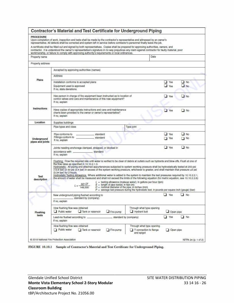
Glendale Unified School District Monte Vista Elementary School 2-Story Modular Classroom Building tBP/Architecture Project No. 21056.00
SITE WATER DISTRIBUTION PIPING 33 14 16 - 26
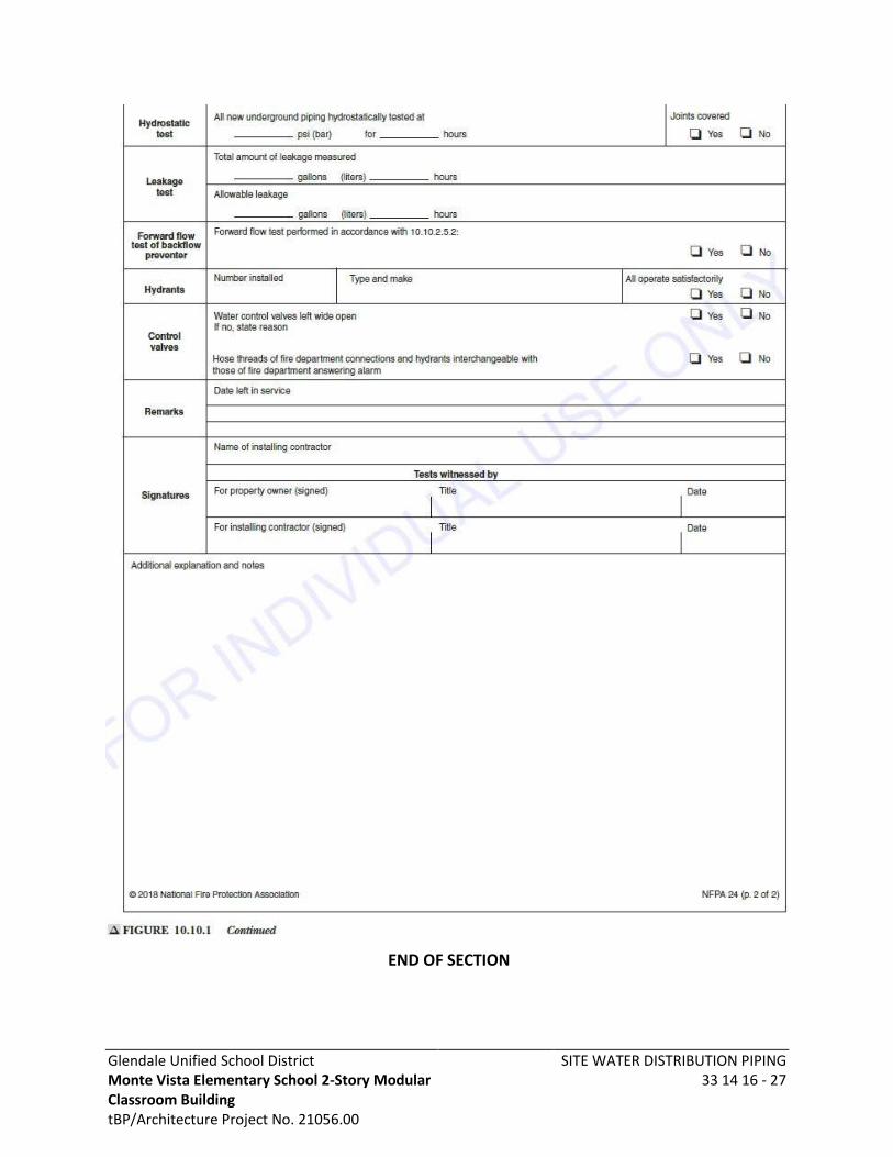
Glendale Unified School District Monte Vista Elementary School 2-Story Modular Classroom Building tBP/Architecture Project No. 21056.00
SITE WATER DISTRIBUTION PIPING 33 14 16 - 27
END OF SECTION
Glendale Unified School District Monte Vista Elementary School 2-Story Modular Classroom Building tBP/Architecture Project No. 21056.00
SANITARY UTILITIES 33 30 00 - 1
SECTION 33 30 00 SANITARY UTILITIES
PART 1 - GENERAL
1.1 SECTION INCLUDES
A. Supply and installation of sanitary sewer system from building wall perimeter, unless noted otherwise, to site sanitary sewer point of connection as shown on Construction Documents.
B. Sewage bypass and pumping plan.
C. Spill prevention & emergency response plan.
D. Closed-circuit television inspection of sewer laterals.
E. Contractor shall furnish all labor, materials, services, testing, transportation and equipment necessary for the completion of all piping and including the demolition and removal of certain equipment, piping and appurtenances all as required and as indicated on drawings and specified herein. Work materials and equipment not indicated or specified which is necessary for the complete and proper operation of the work of this Section in accordance with the true intent and meaning of the contract documents shall be provided and incorporated at no additional cost to the Owner.
1.2 RELATED SECTIONS
A. Trenching Requirements: Conform to the requirements of Section 31 20 00 – Grading.
1.3 SUBMITTALS
A. Product Data:
1. Manufacturer’s Catalog data for materials. Include technical data for pipe, gaskets, joints, couplings, pumps, pump basin, pump controller and all pump accessories, cleanout yard box with lid, sand bedding, tracer wire and detectable warning tape.
B. Closeout Submittal: Submit three DVD’s of Closed-circuit television inspections performed. Include the following information:
1. Electronic Media Recordings: Visual and audio record of the entire length of pipe. For existing laterals identify problem areas, such as roots, cracks, fractures, broken pipe, and other unusual conditions found.
2. Digital Photographs of the pipe condition, connections, points of interest and defects found. Indicate distance of defects to a point of reference such as face of building or mainline.
3. Inspection Log: Provide written report including: