2002tutorial - harmonic filters tutorial 1 mte corporation harmonic filters for power conversion...
TRANSCRIPT
Harmonics Tutorial 1MTE CORPORATION
Harmonic Filters for Power Conversion Equipment(Drives, rectifiers, etc)
Effects of HarmonicsIEEE - 519Solutions
Harmonics Tutorial 2MTE CORPORATION
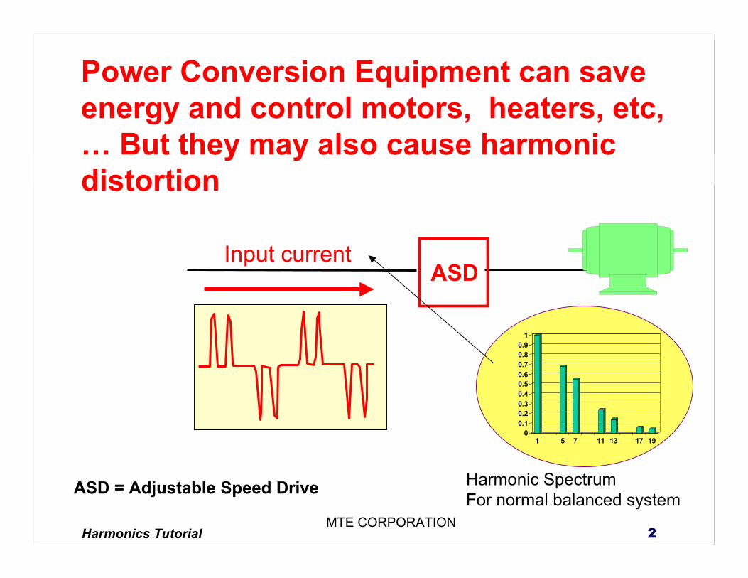
Power Conversion Equipment can save energy and control motors, heaters, etc, … But they may also cause harmonic distortion
Input current
00.10.20.30.40.50.60.70.80.9
1
1 5 7 11 13 17 19
ASD
Harmonic SpectrumFor normal balanced system
ASD = Adjustable Speed Drive
Harmonics Tutorial 3MTE CORPORATION
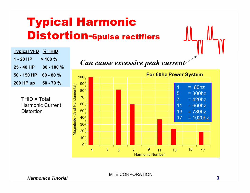
Typical Harmonic Distortion-6pulse rectifiers
1 3 5 7 9 11 13 15 170
10
20
30
40
50
60
70
80
90
100M
agni
tude
(% o
f Fun
dam
enta
l)
Harmonic Number
1 = 60hz5 = 300hz7 = 420hz11 = 660hz13 = 780hz17 = 1020hz
Can cause excessive peak currentTypical VFD % THID
1 - 20 HP > 100 %
25 - 40 HP 80 - 100 %
50 - 150 HP 60 - 80 %
200 HP up 50 - 70 %
THID = Total Harmonic Current Distortion
For 60hz Power System

Harmonics Tutorial 4MTE CORPORATION
Expected input harmonics for given total input impedance for 6-pulse rectifier (6-diode, 3-phase bridge rectifier)
Harmonic Number
.50% Z
1.0% Z
1.5% Z
2.0% Z
2.5% Z
3.0%Z
5th 0.8 0.6 0.5 0.46 0.42 0.4
7th 0.6 0.37 0.3 0.22 0.2 0.16
11th 0.18 0.12 0.1 0.09 0.08 0.073
13th 0.1 0.075 0.06 0.058 0.05 0.049
17th 0.073 0.052 0.04 0.036 0.032 0.03
19th 0.06 0.042 0.03 0.028 0.025 0.022
%THID 102.5 72.2 59.6 52.3 47.6 44.13
Amps Increase
43%
23%
17%
13%
11%
9%
Harmonic Current Distortionis a function of source impedance
Harmonics Tutorial 5MTE CORPORATION
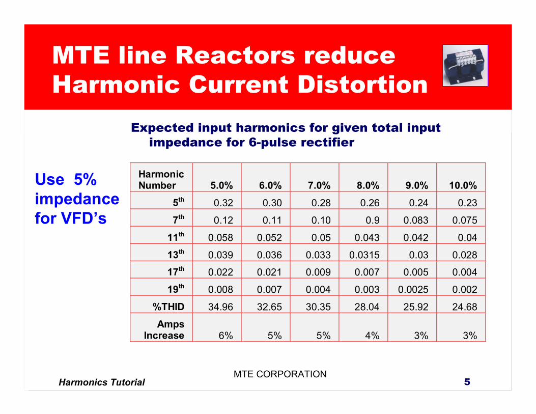
Expected input harmonics for given total input impedance for 6-pulse rectifier
HarmonicNumber 5.0% 6.0% 7.0% 8.0% 9.0% 10.0%
5th 0.32 0.30 0.28 0.26 0.24 0.23
7th 0.12 0.11 0.10 0.9 0.083 0.075
11th 0.058 0.052 0.05 0.043 0.042 0.04
13th 0.039 0.036 0.033 0.0315 0.03 0.028
17th 0.022 0.021 0.009 0.007 0.005 0.004
19th 0.008 0.007 0.004 0.003 0.0025 0.002
%THID 34.96 32.65 30.35 28.04 25.92 24.68
AmpsIncrease 6% 5% 5% 4% 3% 3%
MTE line Reactors reduce Harmonic Current Distortion
Use 5% impedance for VFD’s
Harmonics Tutorial 6MTE CORPORATION
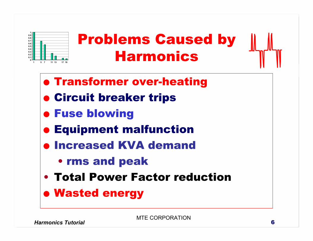
Problems Caused by Harmonics
Transformer over-heatingCircuit breaker tripsFuse blowingEquipment malfunctionIncreased KVA demand• rms and peak
• Total Power Factor reductionWasted energy
00.10.20.30.40.50.60.70.80.9
1
1 5 7 11 13 17 19
Harmonics Tutorial 7MTE CORPORATION
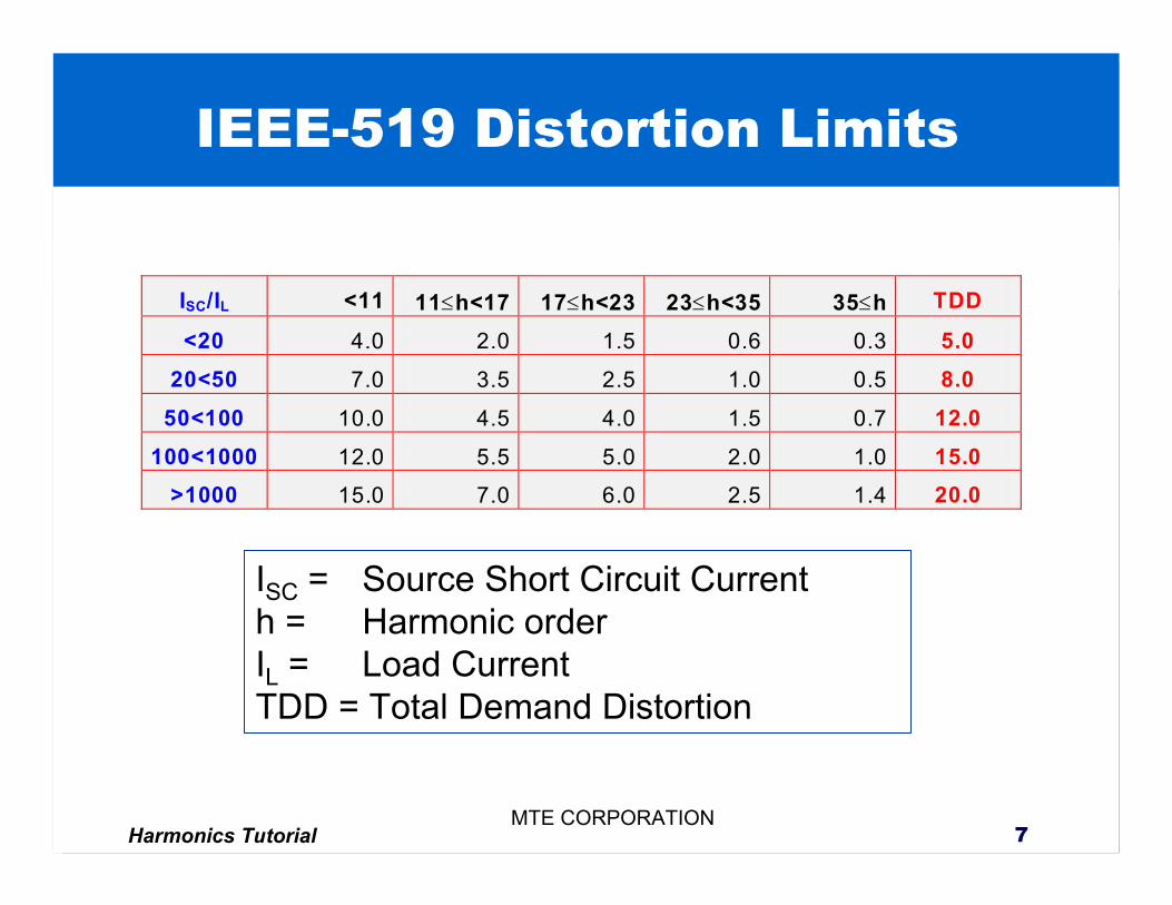
IEEE-519 Distortion Limits
ISC/IL <11 11≤h<17 17≤h<23 23≤h<35 35≤h TDD
<20 4.0 2.0 1.5 0.6 0.3 5.0 20<50 7.0 3.5 2.5 1.0 0.5 8.0
50<100 10.0 4.5 4.0 1.5 0.7 12.0 100<1000 12.0 5.5 5.0 2.0 1.0 15.0
>1000 15.0 7.0 6.0 2.5 1.4 20.0
ISC = Source Short Circuit Currenth = Harmonic orderIL = Load CurrentTDD = Total Demand Distortion
Harmonics Tutorial 8MTE CORPORATION
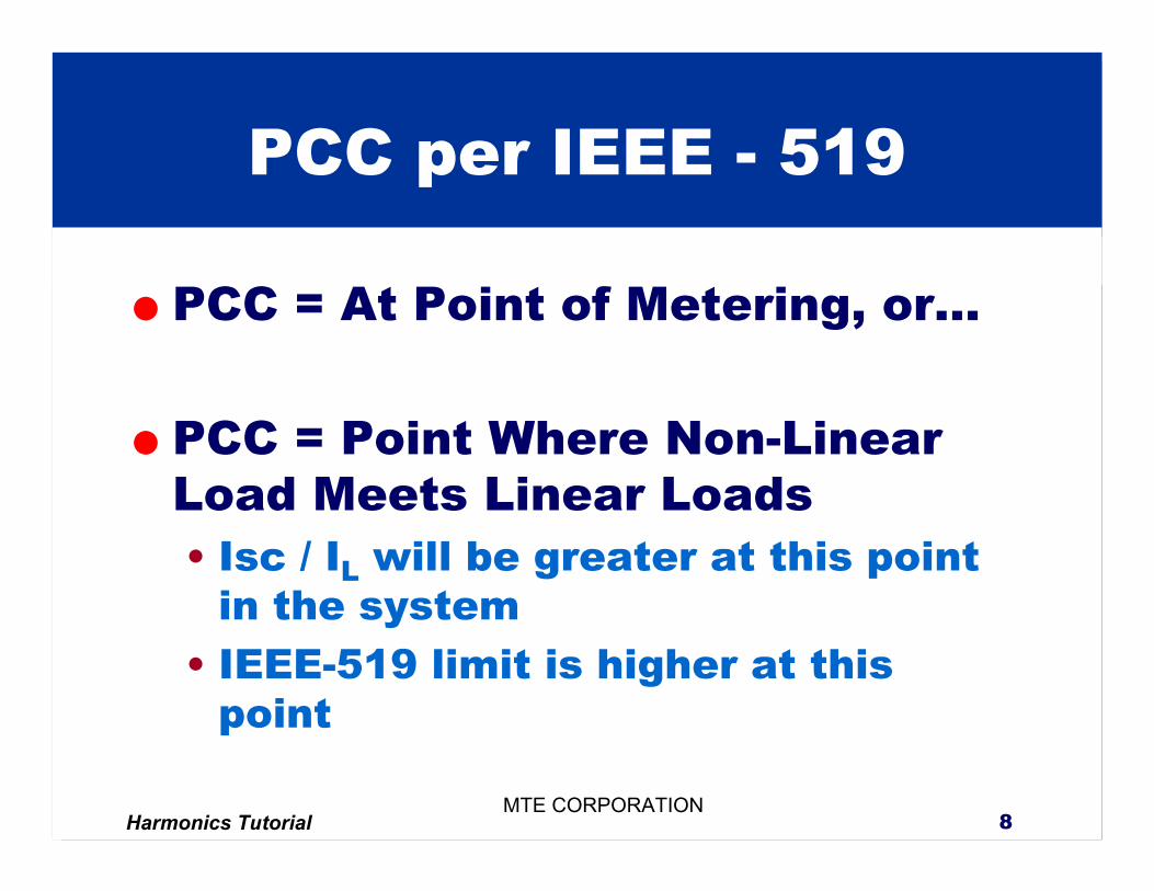
PCC = At Point of Metering, or…
PCC = Point Where Non-Linear Load Meets Linear Loads• Isc / IL will be greater at this point
in the system• IEEE-519 limit is higher at this
point
PCC per IEEE - 519
Harmonics Tutorial 9MTE CORPORATION
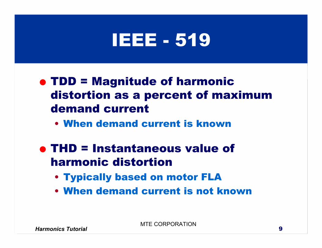
TDD = Magnitude of harmonic distortion as a percent of maximum demand current• When demand current is known
THD = Instantaneous value of harmonic distortion• Typically based on motor FLA• When demand current is not known
IEEE - 519
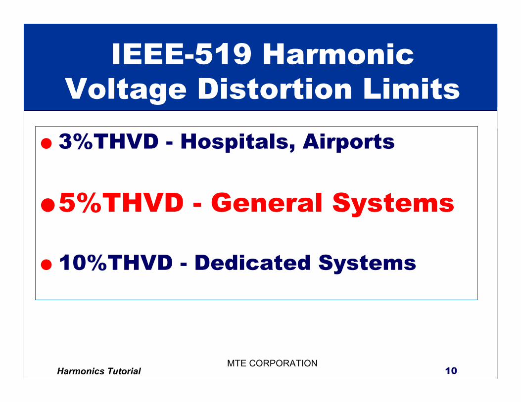
Harmonics Tutorial 10MTE CORPORATION
IEEE-519 Harmonic Voltage Distortion Limits3%THVD - Hospitals, Airports
5%THVD - General Systems
10%THVD - Dedicated Systems
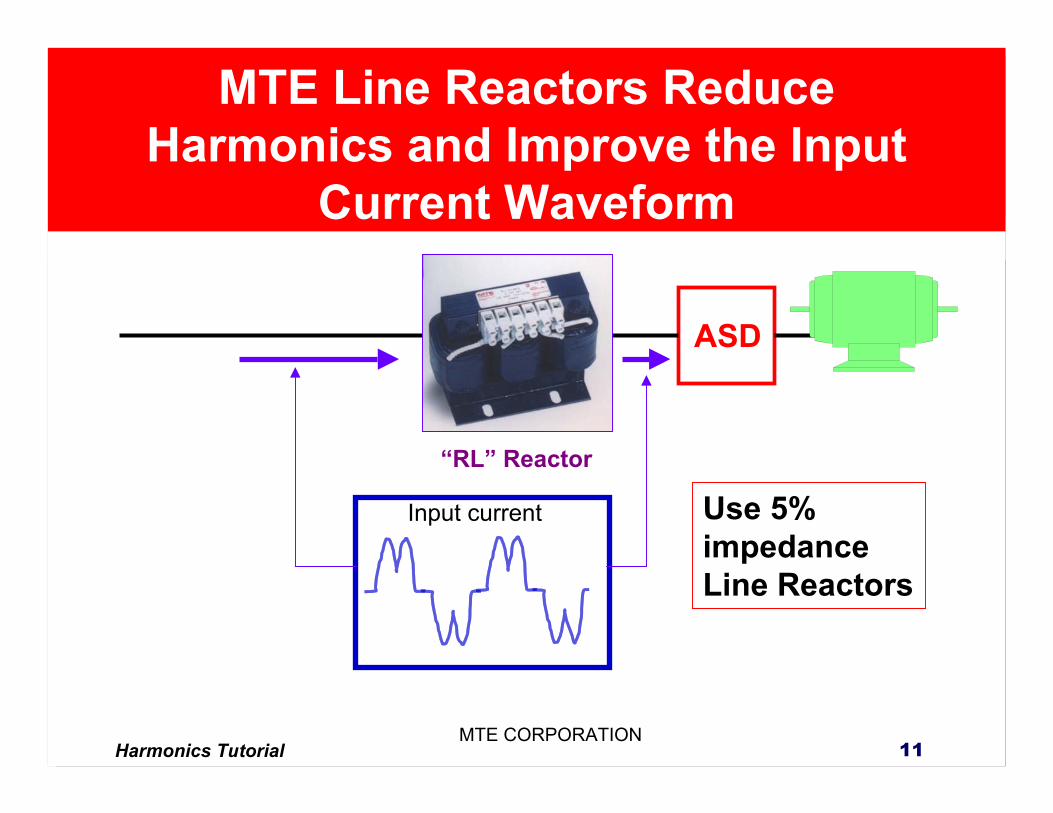
Harmonics Tutorial 11MTE CORPORATION
Input current
ASD
“RL” Reactor
MTE Line Reactors Reduce Harmonics and Improve the Input
Current Waveform
Use 5% impedance Line Reactors
Harmonics Tutorial 12MTE CORPORATION
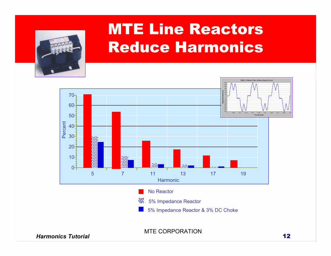
115 7 13 17 190
10
20
30
40
50
60
70
Perc
ent
Harmonic
No Reactor
5% Impedance Reactor
5% Impedance Reactor & 3% DC Choke
150HP, 12% Matrix Filter at Rated Output Current
-350
-300
-250
-200
-150
-100
-50
0
50
100
150
200
250
300
350
0 0.005 0.01 0.015 0.02 0.025 0.03 0.035 0.04 0.045 0.05
Time [seconds]
Mag
nitu
de [A
mpe
res]
MTE Line Reactors Reduce Harmonics
Harmonics Tutorial 13MTE CORPORATION
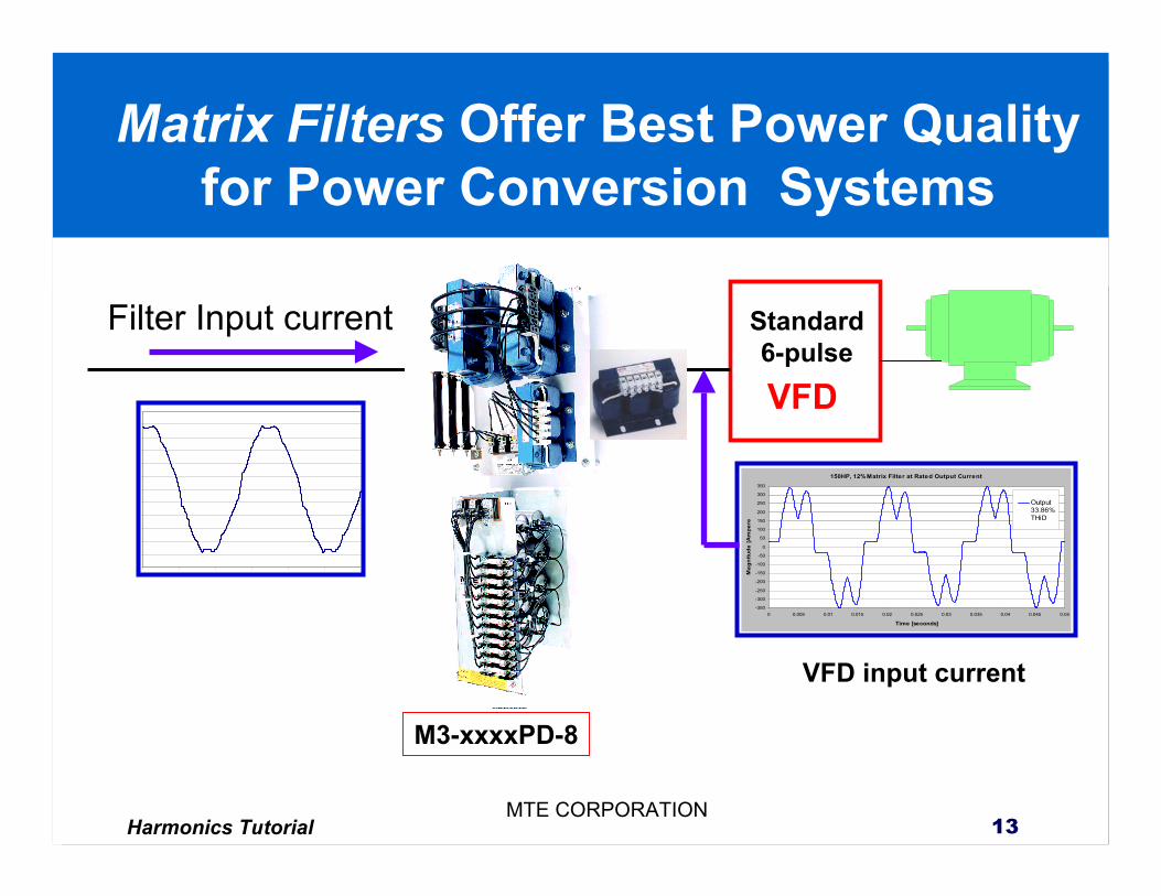
Filter Input current
VFD
150HP, 12% Matrix Filter at Rated Output Current
-350
-300
-250
-200
-150
-100
-50
0
50
100
150
200
250
300
350
0 0.005 0.01 0.015 0.02 0.025 0.03 0.035 0.04 0.045 0.05
Time [seconds]
Mag
nitu
de [A
mpe
re
Output33.86%THiD
Standard6-pulse
VFD input current
M3-xxxxPD-8
Matrix Filters Offer Best Power Quality for Power Conversion Systems
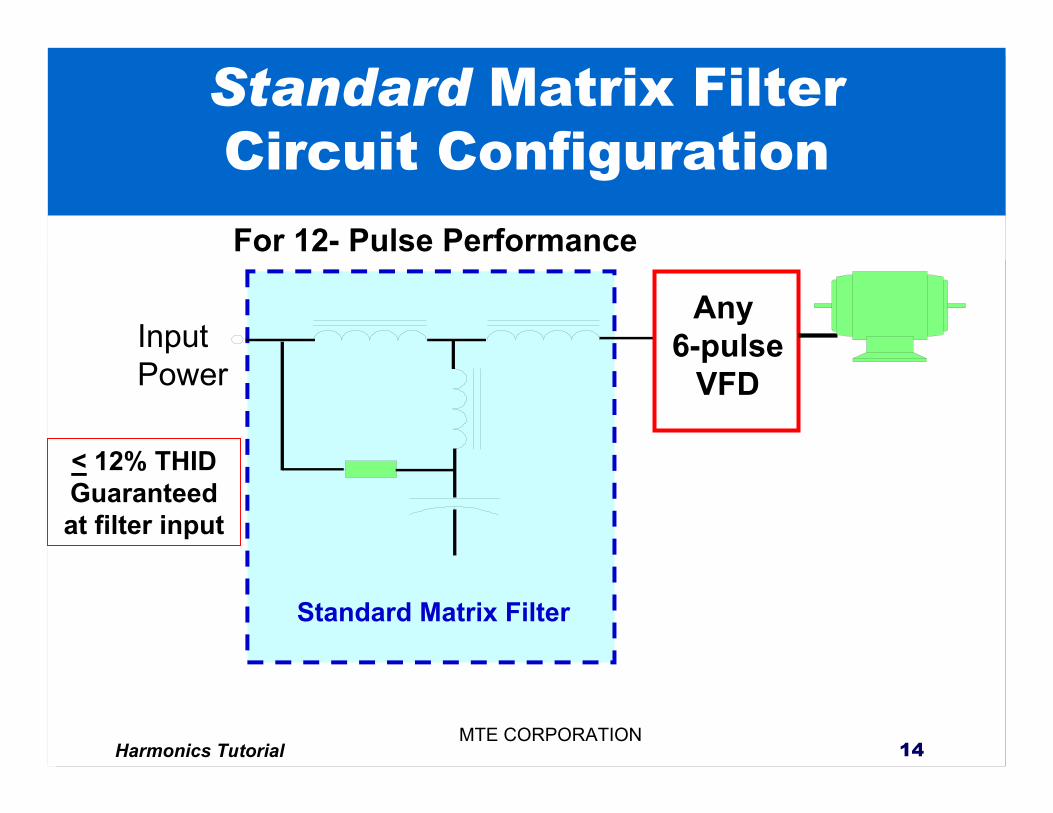
Harmonics Tutorial 14MTE CORPORATION
Standard Matrix Filter Circuit Configuration
InputPower
Any 6-pulse
VFD
Standard Matrix Filter
< 12% THIDGuaranteed at filter input
For 12- Pulse Performance
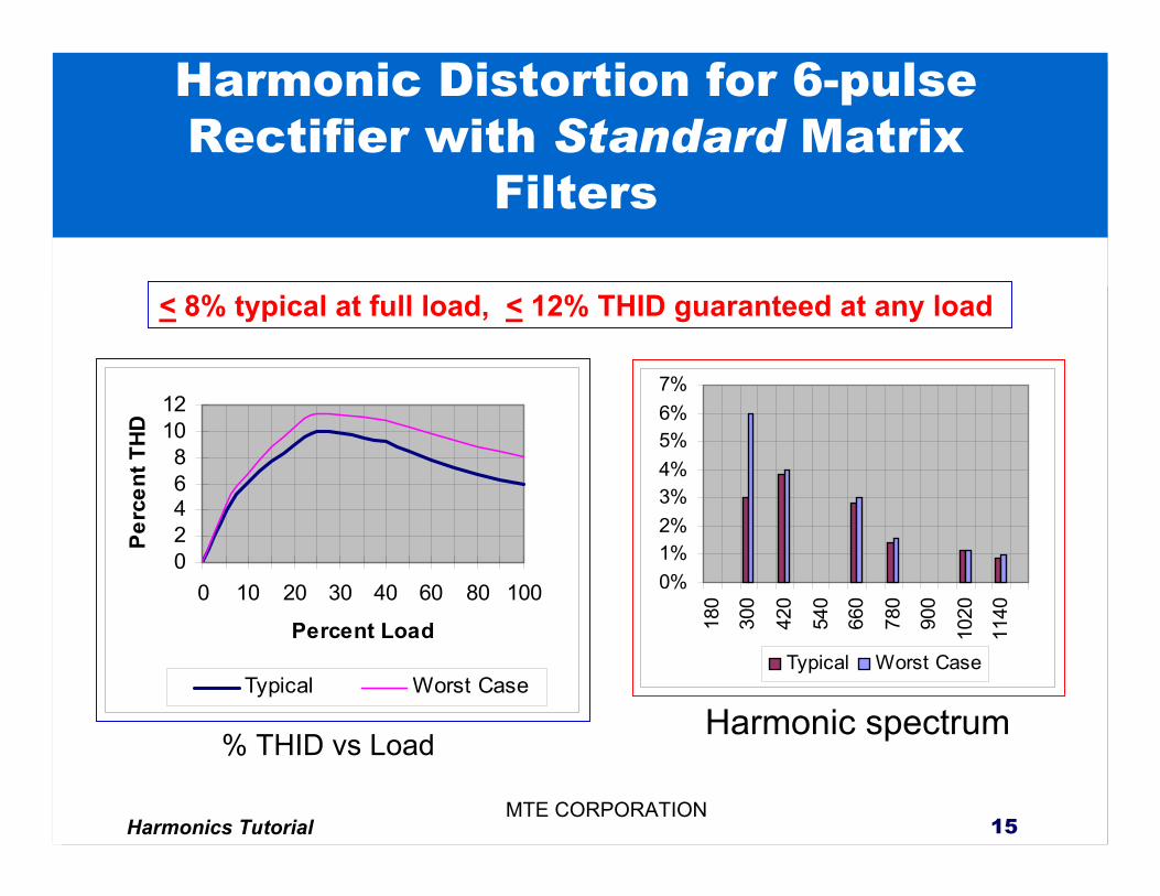
Harmonics Tutorial 15MTE CORPORATION
Harmonic Distortion for 6-pulse Rectifier with Standard Matrix
Filters
02468
1012
0 10 20 30 40 60 80 100
Percent Load
Perc
ent T
HD
Typical Worst Case
0%1%2%3%4%5%6%7%
180
300
420
540
660
780
900
1020
1140
Typical Worst Case
Harmonic spectrum% THID vs Load
< 8% typical at full load, < 12% THID guaranteed at any load
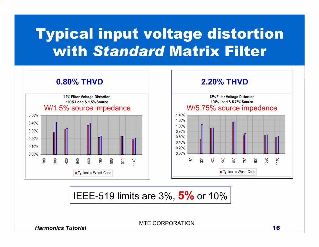
Harmonics Tutorial 16MTE CORPORATION
Typical input voltage distortion with Standard Matrix Filter
12% Filter Voltage Distortion100% Load & 1.5% Source
0.00%
0.10%
0.20%
0.30%
0.40%
0.50%
180
300
420
540
660
780
900
1020
1140
Typical Worst Case
12% Filter Voltage Distortion100% Load & 5.75% Source
0.00%0.20%0.40%0.60%0.80%1.00%1.20%1.40%
180
300
420
540
660
780
900
1020
1140
Typical Worst Case
W/1.5% source impedance W/5.75% source impedance
IEEE-519 limits are 3%, 5% or 10%
0.80% THVD 2.20% THVD
Harmonics Tutorial 17MTE CORPORATION
0
0
0
0
0
0
0
0
0
0
0
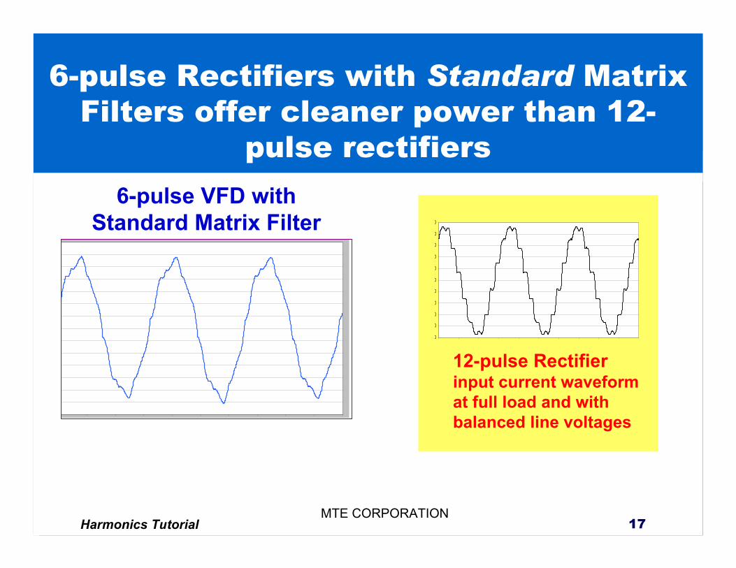
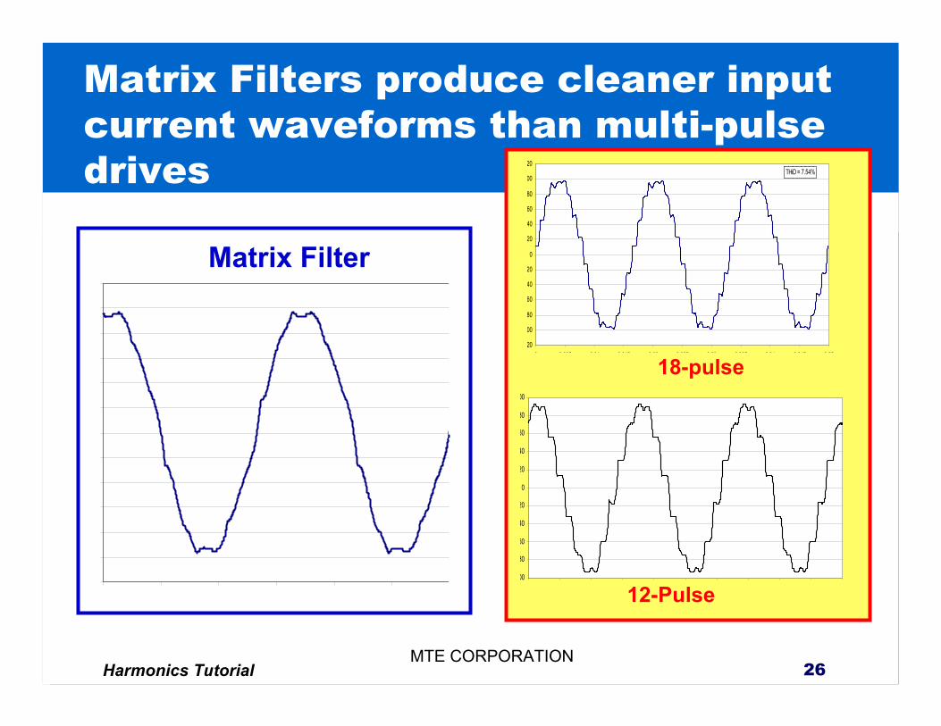
6-pulse VFD with Standard Matrix Filter
12-pulse Rectifierinput current waveform at full load and with balanced line voltages
6-pulse Rectifiers with Standard Matrix Filters offer cleaner power than 12-
pulse rectifiers
Harmonics Tutorial 18MTE CORPORATION
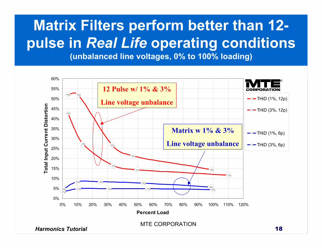
1%
1%
1%
1%
1%
3% 3%
3%
3%
3%
1%1% 1% 1% 1%3%
3% 3% 3%3%
0%
5%
10%
15%
20%
25%
30%
35%
40%
45%
50%
55%
60%
0% 10% 20% 30% 40% 50% 60% 70% 80% 90% 100% 110% 120%
Percent Load
Tota
l Inp
ut C
urre
nt D
isto
rtio
n
1 % THiD (1%, 12p)
3 % THiD (3%, 12p)
1 % THiD (1%, 6p)
3 % THiD (3%, 6p)
12 Pulse w/ 1% & 3%
Line voltage unbalance
Matrix w 1% & 3%
Line voltage unbalance
Matrix Filters perform better than 12-pulse in Real Life operating conditions
(unbalanced line voltages, 0% to 100% loading)
Harmonics Tutorial 19MTE CORPORATION
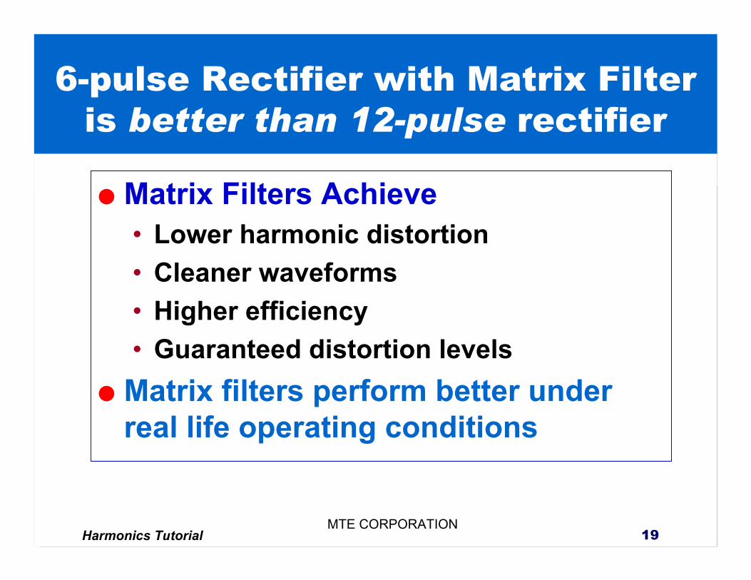
6-pulse Rectifier with Matrix Filter is better than 12-pulse rectifier
Matrix Filters Achieve• Lower harmonic distortion• Cleaner waveforms• Higher efficiency• Guaranteed distortion levels
Matrix filters perform better under real life operating conditions
Harmonics Tutorial 20MTE CORPORATION
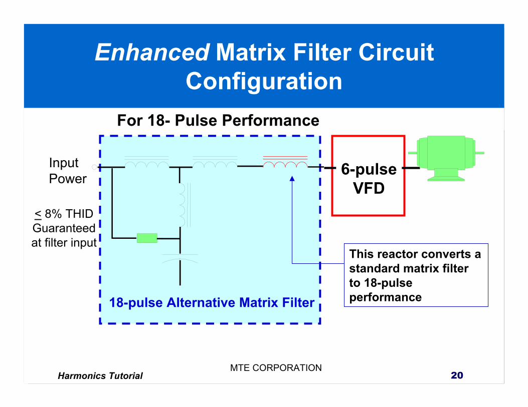
Enhanced Matrix Filter Circuit Configuration
InputPower 6-pulse
VFD
18-pulse Alternative Matrix Filter
This reactor converts a standard matrix filter to 18-pulse performance
< 8% THIDGuaranteed at filter input
For 18- Pulse Performance
Harmonics Tutorial 21MTE CORPORATION
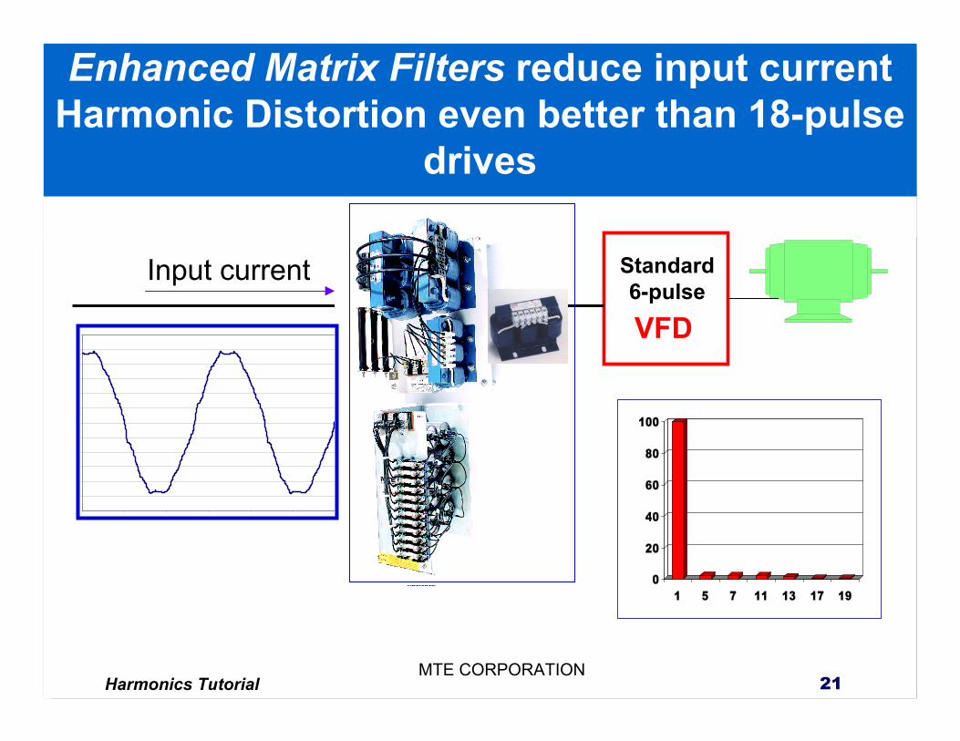
Enhanced Matrix Filters reduce input current Harmonic Distortion even better than 18-pulse
drives
Input current
VFD
Standard6-pulse
0
20
40
60
80
100
1 5 7 11 13 17 19
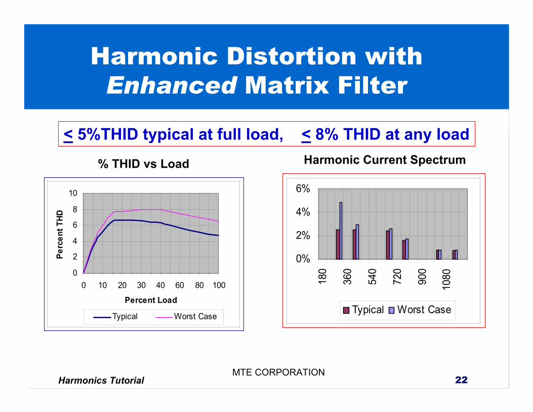
Harmonics Tutorial 22MTE CORPORATION
Harmonic Distortion with Enhanced Matrix Filter
0
2
4
6
8
10
0 10 20 30 40 60 80 100
Percent Load
Perc
ent T
HD
Typical Worst Case
0%
2%
4%
6%
180
360
540
720
900
1080
Typical Worst Case
% THID vs Load Harmonic Current Spectrum
< 5%THID typical at full load, < 8% THID at any load
Harmonics Tutorial 23MTE CORPORATION
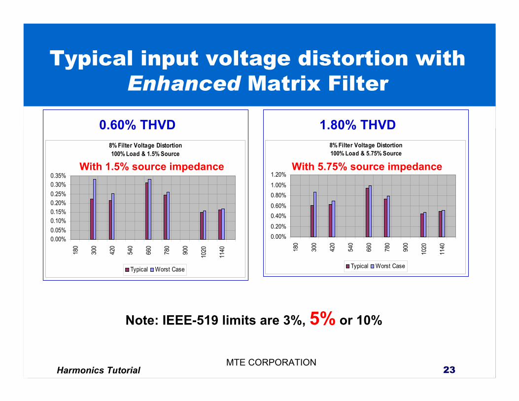
Typical input voltage distortion with Enhanced Matrix Filter
8% Filter Voltage Distortion100% Load & 1.5% Source
0.00%0.05%0.10%0.15%0.20%0.25%0.30%0.35%
180
300
420
540
660
780
900
1020
1140
Typical Worst Case
8% Filter Voltage Distortion100% Load & 5.75% Source
0.00%0.20%0.40%0.60%0.80%1.00%1.20%
180
300
420
540
660
780
900
1020
1140
Typical Worst Case
With 1.5% source impedance With 5.75% source impedance
Note: IEEE-519 limits are 3%, 5% or 10%
0.60% THVD 1.80% THVD
Harmonics Tutorial 24MTE CORPORATION
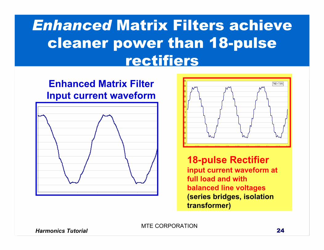
Enhanced Matrix Filter Input current waveform
18-pulse Rectifierinput current waveform at full load and with balanced line voltages(series bridges, isolation transformer)
Enhanced Matrix Filters achieve cleaner power than 18-pulse
rectifiers
20
00
80
60
40
20
0
20
40
60
80
00
20
0 0 005 0 01 0 015 0 02 0 025 0 03 0 035 0 04 0 045 0 05
����������������
����������������THiD = 7.54%
Harmonics Tutorial 25MTE CORPORATION
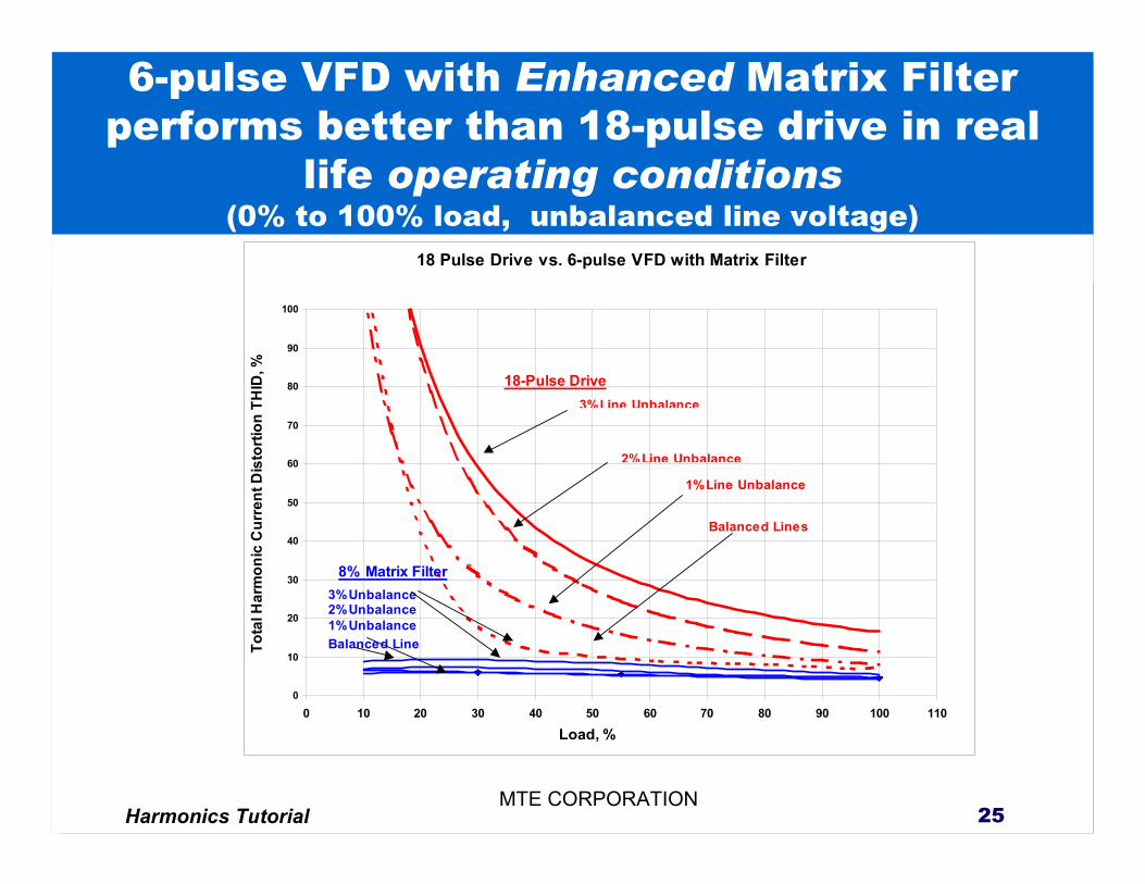
18 Pulse Drive vs. 6-pulse VFD with Matrix Filter
0
10
20
30
40
50
60
70
80
90
100
0 10 20 30 40 50 60 70 80 90 100 110
Load, %
Tota
l Har
mon
ic C
urre
nt D
isto
rtion
TH
ID, %
3%Line Unbalance
2%Line Unbalance
1% Line Unbalance
Balanced Lines
8% Matrix Filter3%Unbalance2% Unbalance1% Unbalance
18-Pulse Drive
Balanced Line
6-pulse VFD with Enhanced Matrix Filter performs better than 18-pulse drive in real
life operating conditions(0% to 100% load, unbalanced line voltage)
Harmonics Tutorial 26MTE CORPORATION
Matrix Filters produce cleaner input current waveforms than multi-pulse drives
20
00
80
60
40
20
0
20
40
60
80
00
20
0 0 005 0 01 0 015 0 02 0 025 0 03 0 035 0 04 0 045 0 05
���������������
���������������THiD = 7.54%
00
80
60
40
20
0
20
40
60
80
00
Matrix Filter
12-Pulse
18-pulse
Harmonics Tutorial 27MTE CORPORATION
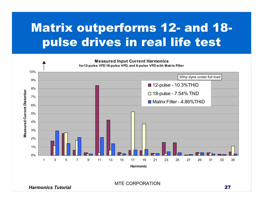
Matrix outperforms 12- and 18-pulse drives in real life test
Measured Input Current Harmonicsfor12-pulse VFD 18-pulse VFD, and 6-pulse VFD with Matrix Filter
0%
1%
2%
3%
4%
5%
6%
7%
8%
9%
10%
1 3 5 7 9 11 13 15 17 19 21 23 25 27 29 31 33 35
Harmonic
Mea
sure
d Cu
rren
t Dis
tort
ion
12-pulse - 10.3%THiD
18-pulse - 7.54% ThiD
Matrix Filter - 4.86%THiD
���������������������������������������������������������������������
���������������������������������������������������������������������30hp dyne under full load

Harmonics Tutorial 28MTE CORPORATION
Standard Matrix Filters are Better Than Harmonic Traps
20% - 30% THID is typical for a 5th Harmonic trap
Input7.24%THiD
5th Harmonic TrapStandard Matrix Filter
Harmonics Tutorial 29MTE CORPORATION
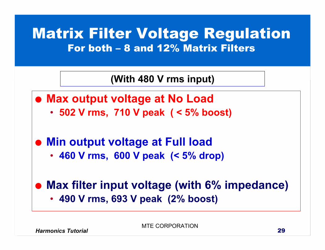
Matrix Filter Voltage Regulation For both – 8 and 12% Matrix Filters
Max output voltage at No Load • 502 V rms, 710 V peak ( < 5% boost)
Min output voltage at Full load• 460 V rms, 600 V peak (< 5% drop)
Max filter input voltage (with 6% impedance)• 490 V rms, 693 V peak (2% boost)
(With 480 V rms input)
Harmonics Tutorial 30MTE CORPORATION
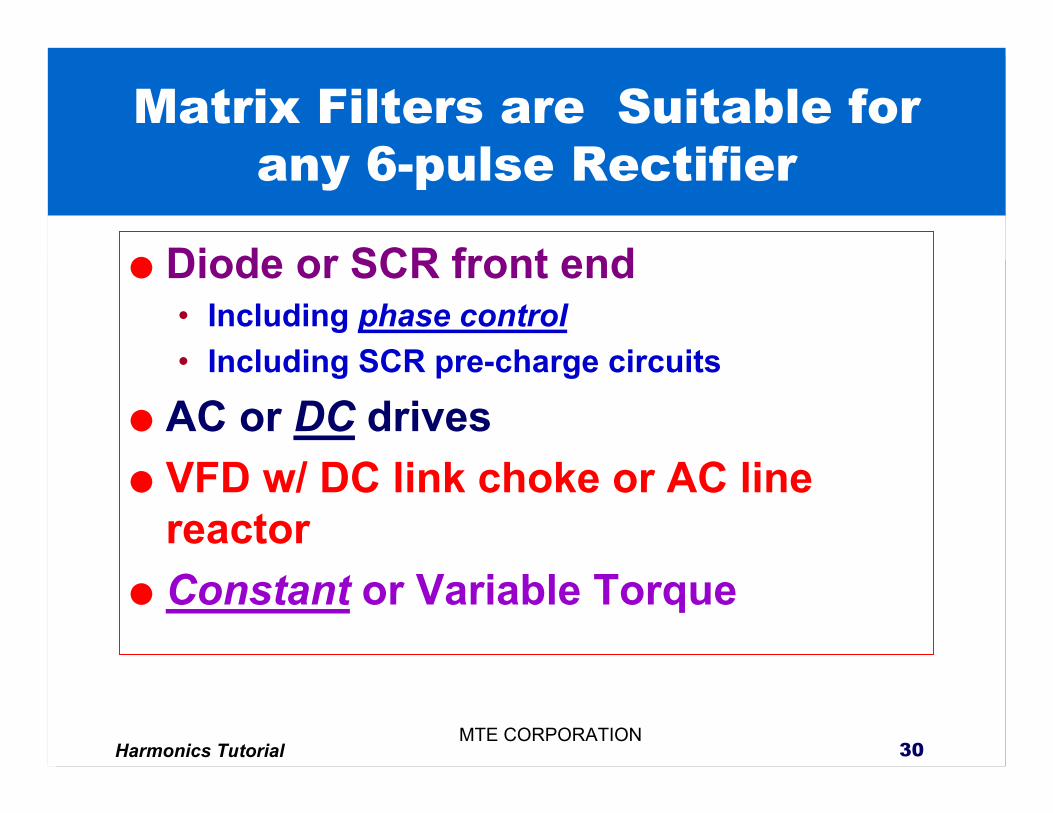
Matrix Filters are Suitable for any 6-pulse Rectifier
Diode or SCR front end• Including phase control• Including SCR pre-charge circuits
AC or DC drivesVFD w/ DC link choke or AC line reactorConstant or Variable Torque
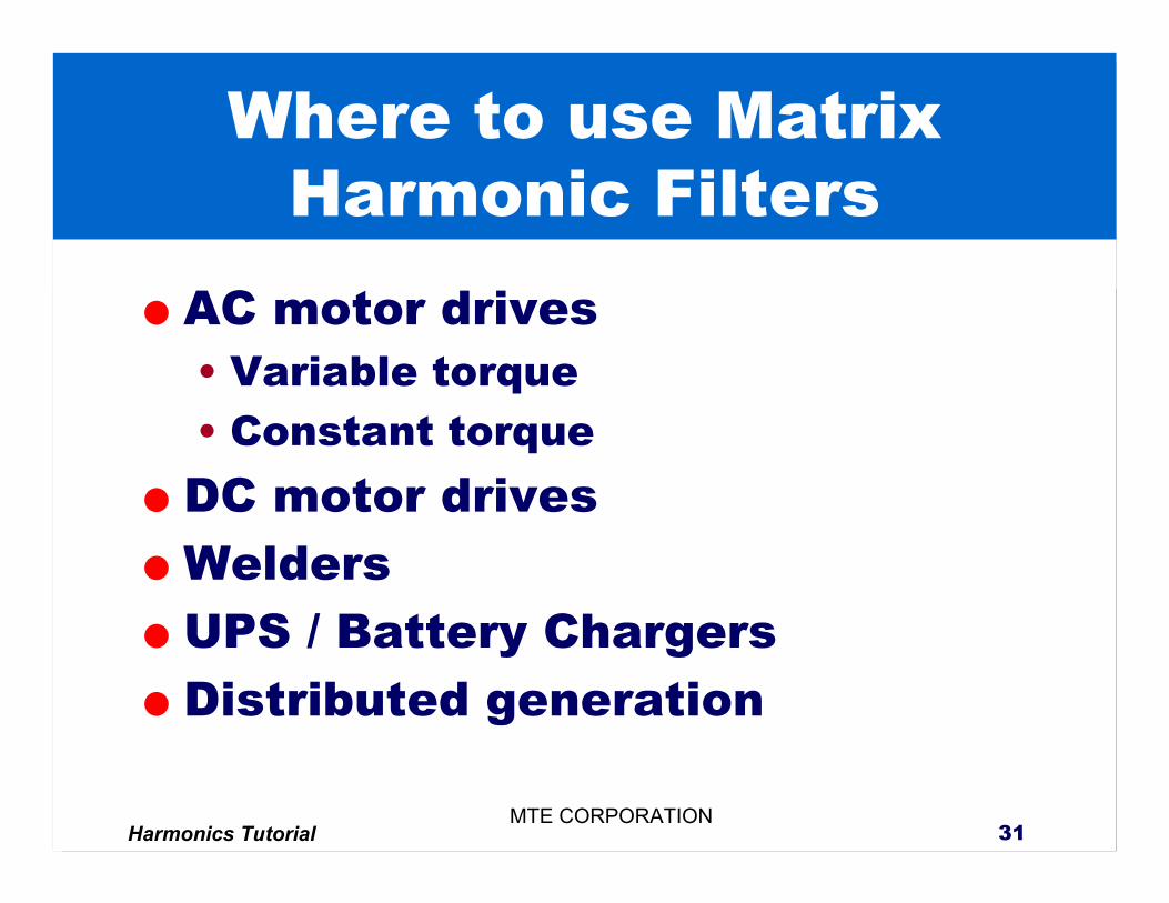
Harmonics Tutorial 31MTE CORPORATION
Where to use Matrix Harmonic Filters
AC motor drives• Variable torque• Constant torqueDC motor drivesWelders UPS / Battery ChargersDistributed generation
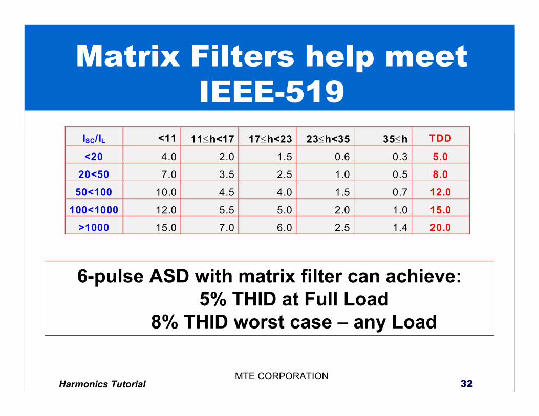
Harmonics Tutorial 32MTE CORPORATION
Matrix Filters help meet IEEE-519
ISC/IL <11 11≤h<17 17≤h<23 23≤h<35 35≤h TDD
<20 4.0 2.0 1.5 0.6 0.3 5.0 20<50 7.0 3.5 2.5 1.0 0.5 8.0
50<100 10.0 4.5 4.0 1.5 0.7 12.0 100<1000 12.0 5.5 5.0 2.0 1.0 15.0
>1000 15.0 7.0 6.0 2.5 1.4 20.0
6-pulse ASD with matrix filter can achieve:5% THID at Full Load
8% THID worst case – any Load
Harmonics Tutorial 33MTE CORPORATION
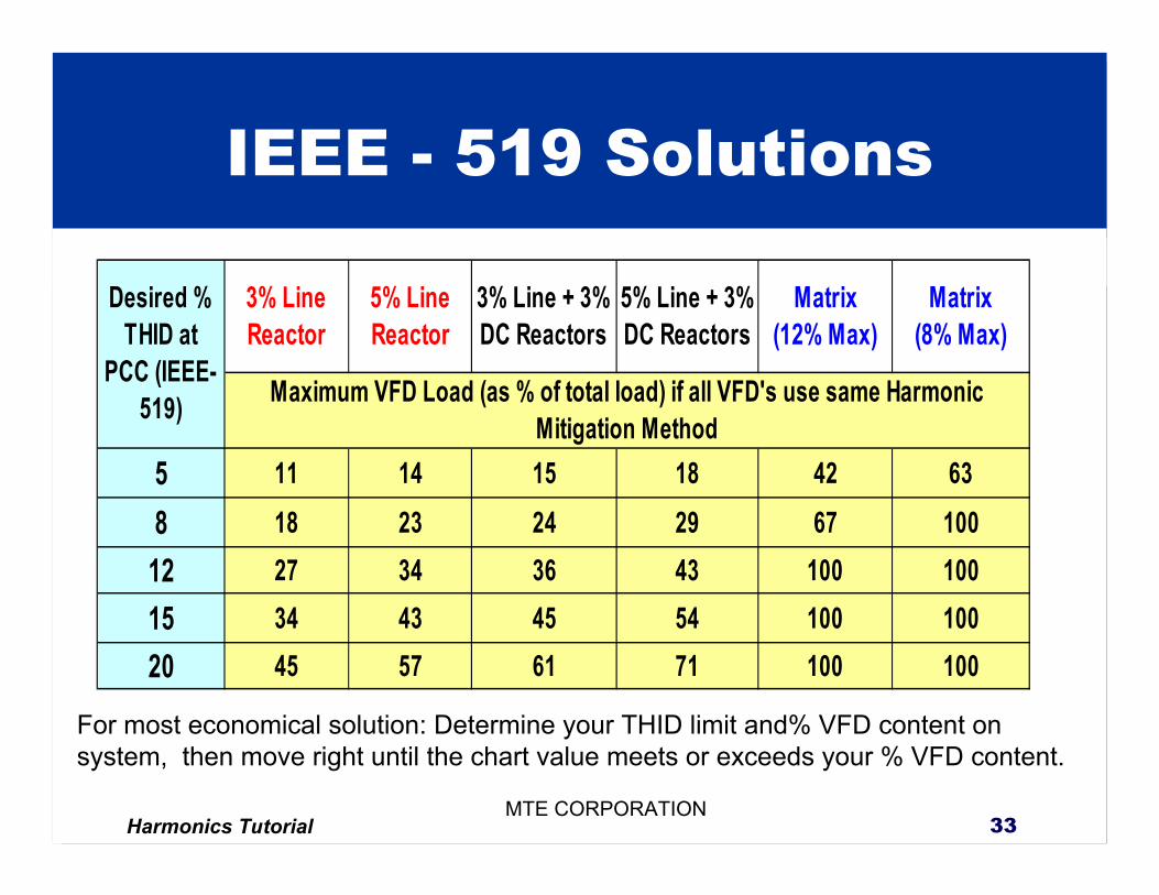
IEEE - 519 Solutions
3% Line Reactor
5% Line Reactor
3% Line + 3% DC Reactors
5% Line + 3% DC Reactors
Matrix (12% Max)
Matrix (8% Max)
5 11 14 15 18 42 638 18 23 24 29 67 100
12 27 34 36 43 100 10015 34 43 45 54 100 10020 45 57 61 71 100 100
Maximum VFD Load (as % of total load) if all VFD's use same Harmonic Mitigation Method
Desired % THID at
PCC (IEEE-519)
For most economical solution: Determine your THID limit and% VFD content on system, then move right until the chart value meets or exceeds your % VFD content.
Harmonics Tutorial 34MTE CORPORATION
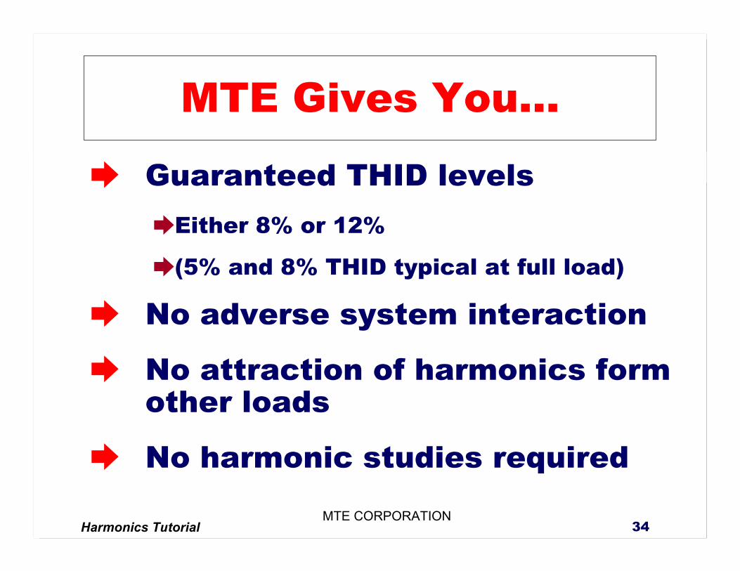
MTE Gives You...
Guaranteed THID levelsEither 8% or 12%
(5% and 8% THID typical at full load)
No adverse system interaction
No attraction of harmonics form other loads
No harmonic studies required
Harmonics Tutorial 35MTE CORPORATION
MTE Field Experience
Over 500,000 line / load reactors
Over 3000 Low Pass Harmonic Filters
Harmonics Tutorial 36MTE CORPORATION