2003 gateway into the past- photogrammetric documentation ...€¦ · close-range...
TRANSCRIPT
GATEWAY INTO THE PAST:
PHOTOGRAMMETRIC DOCUMENTATION OF
THE ARCH, LABNA, YUCATAN, MEXICO 1997By
Lawrence G. Desmond, Ph.D. Senior Research Fellow in Archaeology
Moses Mesoamerican Archive and Research Project Princeton University
Patrick Collins, MSc. Michael Gallie & Partners
London
Archaeologist Tomás Gallareta Negrón Ph.D. Candidate, Tulane University
National Institute of Anthropology and History Merida, Yucatan, Mexico
Archaeologist James Callaghan, MA Director
Foundation of the Autonomous University of Yucatan University Center for the Preservation of the Cultural Heritage of Yucatan
Merida, Yucatan, Mexico
Bibliographic reference:
Desmond, Lawrence G. , Patrick Collins, Tomás Gallareta Negrón, James Callaghan. 2003 Gateway into the past: Photogrammetric documentation of the Arch, Labna, Yucatan, Mexico. In, Luis Barba P., ed., Antropología y Técnica, IIA, UNAM, Vol. 7, pp. 55-66.
Abstract
Convergent-line photogrammetric documentation of the Arch at the archaeological site of Labna was carried out in 1997 in order to evaluate the feasibility and effectiveness of
this type of photogrammetric methodology for use by non-specialists working to document both Maya and Colonial buildings in Yucatan.
The great number of steps in convergent-line drawing systems require time and experience to learn in order to produce detailed field survey information, and drawings. Without the application of standard survey procedures and practices by the development of protocols, the usefulness of the results will vary greatly.
As a survey process convergent-line photogrammetry is in its infancy, but with increased computing power, advances in this software are inevitable. However, in the meanwhile, work needs to be done in process protocols to establish technical procedures and methods for fieldwork when convergent-line photogrammetry is used by non-specialists.
Introduction
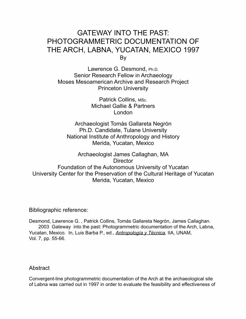
Close-range convergent-line photogrammetric documentation of the Arch at the archaeological site of Labna that was carried out in 1997. This project followed two
Fig. 1. The Arch at Labna, Yucatan, Mexico, west facade. Recorded using convergent-line close-range photogrammetry in 1997 to evaluate this methodology for use by non-photogrammetrists.
Pic: L. G. Desmond, 1997
earlier projects in Yucatan which used a different photogrammetric methodology called close-range stereo-photogrammetry (Desmond 1991 and 1994).
Stereo-photogrammetry employs 2-D photos which are taken is such a way as to create a 3-D image when placed in an optical-mechanical instrument called a stereoplotter which employs software to assist an operator in making drawings from the 3-D image. Convergent-line systems use 2-D photos taken at wide angles from each other, and work with several photos that remain as 2-D images in a digital software environment to make measurable drawings. The application of either of these systems to a particular documentation project requires extensive knowledge of the range of their capabilities.
The first project, in 1989, evaluated stereo-photogrammetry for use by archaeologists by recording La Iglesia building at Chichen Itza and the Adivino Pyramid at Uxmal. In 1990, the Adivino Pyramid was again recorded using stereo-photogrammetry, but this time with a balloon to lift a camera high enough to photograph the upper part of the pyramid, and a total station theodolite to survey control points. Both the west façade of the Adivino Pyramid (30 meters high and about 60 meters at base), and the west façade of La Iglesia were recorded successfully, and drawings of the buildings were made by photogrammetrists using a stereoplotter.
Close-range photogrammetry and conservation of monuments in Yucatan
Close-range photogrammetry using stereo methodology for recording buildings and monuments was developed in Europe during the nineteenth century by Albrecht Meydenbauer (Thompson and Gruner 1980:5 and Borchers 1977:8). While it has had a long history of use for recording architecture in many European countries, it has seen little application in the Americas. The 1989 and 1990 projects in Yucatan gave a firsthand introduction of the method to National Institute of Anthropology and History (INAH) archaeologists who quickly realized the broader implications of its use in conservation projects through out the region. An ongoing photogrammetry program is now being instituted as part of the University Center for the Preservation of the Cultural Heritage of Yucatan (Centro Universitario para la Preservación del Patrimonio Cultural de Yucatán or CUPPCY) at the Autonomous University of Yucatan (UADY) in Merida.
New developments in close-range stereo-photogrammetry
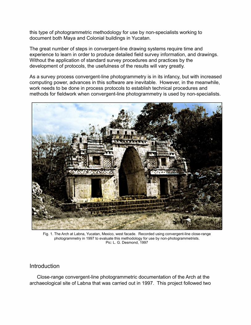
Stereo-photogrammetry has gone through a number of important developments in the past 20 years moving from mechanical to computerized analytical equipment, and most recently to a fully digital environment. The use of newly developed stereo digital drawing equipment such as the Leica Helava system "…[for] non-photogrammetrists, such as in architectural, archaeological, and forensic photogrammetry…digital stereo restitution is nowadays not common" (Fraser 1998:45) (emphasis added).
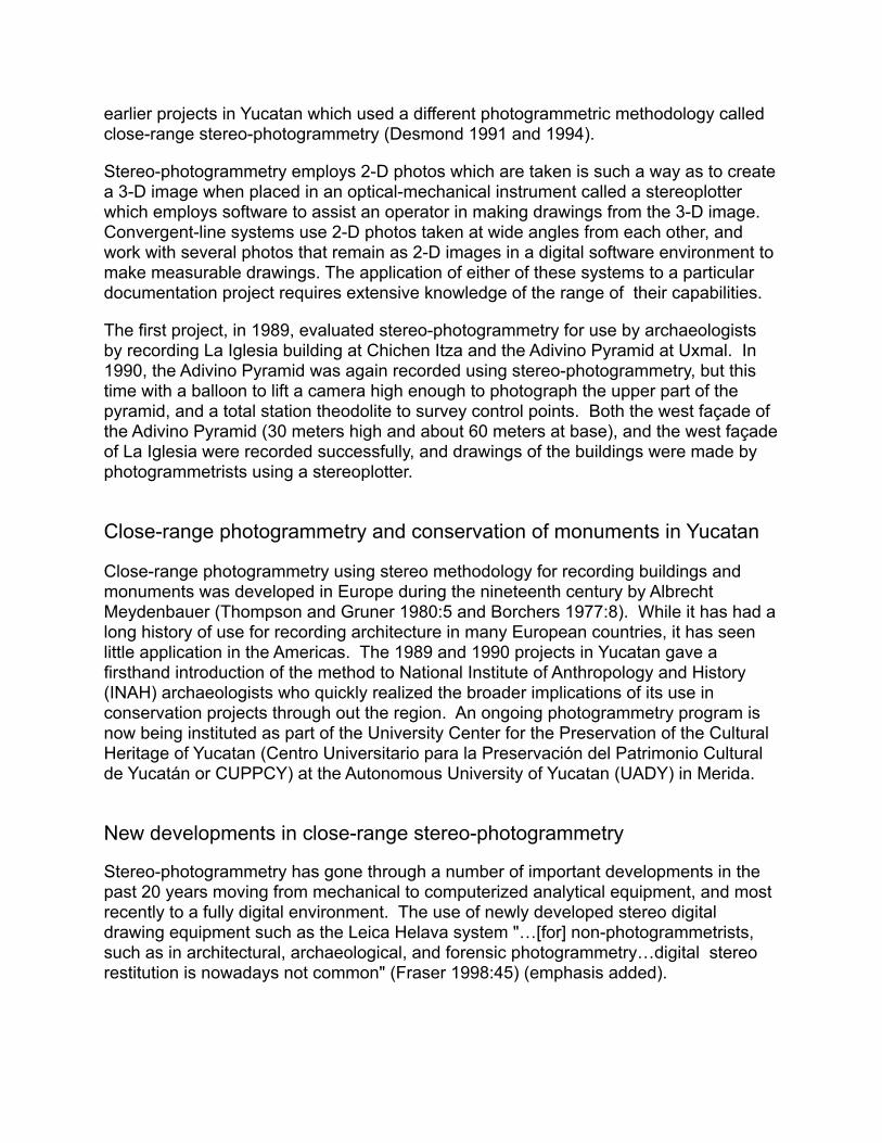
While optical-mechanical instruments called analytical stereoplotters are still widely used by photogrammetrists, they are, like digital systems, seldom used by non-specialists. They can range in price from $25,000 to $150,000. The expense of a stereoplotter, and the training required for its use has discouraged most non-specialists from undertaking projects. The Uxmal and Chichen Itza projects were feasible because an experienced stereoplotter operator with American Measuring Instruments (AMI), a photogrammetry company, made the drawings at no cost to the project.
New developments in close-range convergent-line photogrammetry
Since 1990 there has been considerable development of inexpensive (<$1,000) non-stereo convergent-line digital software programs like PhotoModeler, 3D Builder, Rolleimetric CDW, and FotoG-FMS for use with personal computers (PC). These systems, considered by photogrammetrists to be moderate to low in accuracy, are being used by non-specialists such as archaeologists and architects to make measured drawings of buildings. With the advent of convergent-line software systems, an alternative to stereo-photogrammetry has become available. All of the non-stereo programs include features such as 3-D viewing, rendering, ortho-images, phototexturing, and multiple formats (DXF, VRML, and Wavefront OBJ). The drawing files can be exported to CAD programs for final drawings.
Development of convergent-line photogrammetric software programs parallels the rapid development of PC speed and storage. As PCs increase in their ability to process and store data, they will be able to keep pace with convergent-line software programs which are continually being developed for greater accuracy and simplicity of use by the non-specialist.
Leica SD2000 stereoplotter. Pic: L. G. Desmond, 2000. Michael Clowes working in a 3-D environment to generate an orthophotograph of the Chenes Temple
with the Leica Helava all digital photogrammetric work station. Pic: L. G. Desmond, 2000.
John Garcia with AMI 35/70 stereo-plotter. Pic: L. G. Desmond. 1990.
Fraser, in a recent paper, has rated close-range photogrammetric systems in terms of accuracy and costs:
…tiers [for different systems] are distinguishable in terms of accuracy and cost. At the top rank are the highly automated, high accuracy, high cost (>$100,000) VM systems for industrial photogrammetry… In the middle rank, there are more traditional digital photogrammetric workstations which produce medium accuracy results. The costs of these systems …can be categorized as medium to high (say $10,000 and up). Finally, in the bottom tier we find low accuracy, low cost (<$1,000) [convergent-line] 3D modelling systems. …their clear development focus is toward a much broader market for 3D computer modelling [Fraser 1998: 47-48].
PhotoModeler, one of several convergent-line photogrammetric systems currently available to non-specialists for documentation of architecture, was used to make drawings from field photos of the Arch at Labna. The project was initiated in order to evaluate the effectiveness of PhotoModeler's convergent-line method for use by non-specialists working to document both Maya and Colonial buildings in Yucatan.
Steps in a convergent-line project
Generally, nine steps are required to produce a drawing (called a 3-D model) using convergent-line software systems such as PhotoModeler:
1. Plan the measurement project. 2. Optional: Measure the 3-D locations of selected targets on the object or scene with a surveying instrument. 3. Take photographs of the object or scene using a calibrated or uncalibrated camera. 4. Import scanned or direct digital photographs into the software program. 5. Software program measurement control of the image. 6. Mark selected features on each selected photograph. 7. Identify common marked points in the photographs. 8. Process the data to create a 3-D drawing. 9. Export the resulting 3-D data to a CAD or graphics program for futher processing.
Arch Project convergent-line photogrammetry methodology
1. Planning
Project planning began early in 1997 with discussions with the director of the INAH Labna Research Project and members of the following organizations: the scientific committee of the University Center for Preservation of the Cultural Heritage of Yucatan (CUPPCY), the schools of Anthropological Sciences and of Architecture at the University of Yucatan (UADY), the university foundation (FUADY), and EOS Systems in
Vancouver, Canada, which developed PhotoModeler software. Also participating in the project were students from the schools of anthropology, archaeology, engineering and architecture at UADY.
The Arch was considered ideal for a study of field and drawing procedures because of its moderate size (12 meters long and 6 meters high), and its stonework, which typifies Maya building construction . We could record only the west and east facades of the Arch because the south end of the Arch abuts a mound, and the north end was in such a position that the camera was at a very low angle and too far from the façade.
2. Survey control
East Façade The first step in survey control of the Arch was the placement of 63 red-and-white survey targets measuring 2x3.5 inches on the façade. The targets were accounted for by using numbered 3x5-inch cards set next to each target. The purpose of the targets was to provide easily identified common points of reference in each photo during drawing, and to increase the accuracy of the drawing by surveying the 3-D location of each target with a total station surveying instrument and using these as control points.
While targets are not required to make drawings using PhotoModeler or similar programs, the purpose of this project was to determine how much work was involved, and what level of accuracy might be achieved by using targets. Unfortunately, survey data from this façade and the west facade had a number of ambiguities, so the data could not be used to increase drawing accuracy. However, the targets were still useful as common reference points.
And, the targets were the end points for a few hand measurements taken at the time of the survey, and were useful for measurement control during drawing of the elevation. For example, the distance between targets 1 and 10 was 252 cm, and between 60 and 61 was 499 cm.
West Façade The next step in the fieldwork was to record the west façade of the Arch. As with the east façade, we placed red-and-white survey targets with number cards at locations we thought would provide common points of reference in the photos when making drawings, and for survey points to increase the accuracy of our final drawing. Because we wanted to reduce the time required to place and survey the targets, we used 27 targets on the west façade.
3. Photography
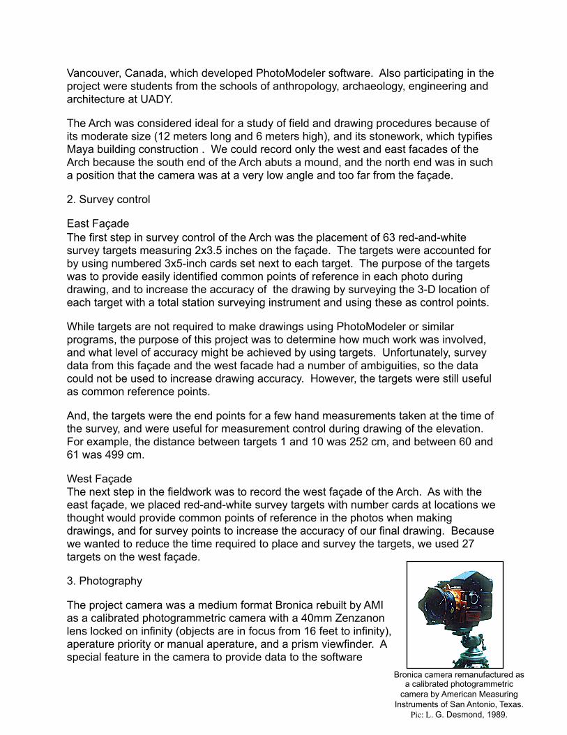
The project camera was a medium format Bronica rebuilt by AMI as a calibrated photogrammetric camera with a 40mm Zenzanon lens locked on infinity (objects are in focus from 16 feet to infinity), aperature priority or manual aperature, and a prism viewfinder. A special feature in the camera to provide data to the software
Bronica camera remanufactured as a calibrated photogrammetric
camera by American Measuring Instruments of San Antonio, Texas.
Pic: L. G. Desmond, 1989.
program to correct for film expansion and contraction was an electromagnetically activated film flattener which pressed the film against a glass plate etched with a grid of 25 micrometer measured réseau crosses.
East Façade Twenty-two color transparencies of the east side of the Arch using Kodak Professional Ektachrome E100S, 220 size film, were taken by Desmond. The first set of 14 photos of the east facade were taken in the afternoon at a variety of angles (generally, 50-90 degrees from eachother) and elevations wide enough to provide the best coverage of the facade for analysis by the convergent-line software software. A second set of eight photos was taken in the morning of the following day because deep shadows from trees in the previous afternoon had darkened parts of the facade. Photos were taken about 16 feet from the façade, and a sketch plan was made of camera positions and angles to keep track of the work. While a tripod was not used in this project, it is highly recommended to insure the sharpness of the images, and to foster a slower and more methodical photographic procedure. Photography took less than one half hour on both days.
To provide an indication of vertical in the photos, a weighted string through the center of two highly visible rubber balls about 2.6 inches in diameter (6.5 cm), separated by 6.5 feet (2 meters) on center, was hung from the façade.
West Façade The Bronica camera was again used to photograph the west façade with Kodak Professional Ektachrome E100S, 220 size film. Eleven photos were taken in mid-afternoon at different angles and elevations in about one half hour. The lighting was more even on the west façade with fewer shadows than on the east facade, and therefore the west side was selected for drawing.
A vertical line in the photos was again provided by a string through the center of two highly visible balls about 2.6 inches in diameter (6.5 cm), separated by 6.5 feet (2 meters) on center, and hung from the façade. As on the east façade, additional scale information was recorded by measuring the distance between selected targets. The distance from target 6 to target 7 was 93 cm, and from target 19 to target was 390 cm. The placement of the 27 targets took about one an one-half hours.
4. Importing scanned images
The 2x2 inch color transparencies were scanned at 800 dpi (800 pixels per inch horizontal, and 800 pixels per inch vertical) using an Agfa Arcus II, 48 bit, flatbed scanner. The scanned images, each about 10 megabytes in size, were saved on Iomega 100 megabyte disks, and mailed to Patrick Collins of Michael Gallie & Partners, a land surveying practice based in London. Collins, who has extensive experience in the application of PhotoModeler to the drawing of architecture, evaluated the field photographs and data to see if it was feasible to create a drawing from them.
After a review of the photos, Collins noted that most of the east façade photos were taken in very bright sunlight which resulted in no visible detail within the shadow areas, and some loss of detail in many highlighted areas. Consequently, he decided to proceed with the more evenly lighted west façade.
The scanned photos of that elevation had lost some resolution and had a dull-grey washed-out appearance which obscured the edges of the uneven cut stones. Because the digital images were darker with a grayish cast as if underexposed, only 75% of the réseau crosses for photo measurement control could be used. Réseau crosses are etched onto a glass plate within the camera on which the film is pressed by a pressure plate at exposure. The known distances between the crosses on the images allows the software program to correct for expansion and contraction of the negative material resulting in greater accuracy of the final drawing.
Finally, the images were converted to greyscale which reduced their file size to about 40% while improving the speed of manipulation in PhotoModeler. Converted images lose no detail, and are just as accurate as the scanned color image.
5. Software program control of the image
As noted previously, PhotoModeler can use survey targets to increase accuracy. But the target survey information in this project contained ambiguities which made its accuracy uncertain. If target coordinates contain errors, PhotoModeler will process them if they are entered, but the resultant drawing will be inaccurate. It was decided to proceed without using the target survey data.
For PhotoModeler to measure the image information in a photograph, it needs values for some specific parameters of the camera. Generally we need to know the focal length of the lens, the digitizing scale (which is the CCD format size of a scanner or digital camera), and the principal point (where the optical axis of the lens intersects the photograph). Because the Bronica camera had been rebuilt and calibrated by AMI, the required camera information was available and could be entered into the program.
The definition of the location of the réseau marks provided by AMI in its camera data sheet was different from that used by PhotoModeler, but Alan Walford at EOS Systems, developers of PhotoModeler, solved the problem with interpolation between the two systems. The position of the remaining visible réseau crosses were then marked on each of the scanned photographs. Since only 75% of the crosses could be marked the achievable accuracies were again slightly lessened.
We had to create in PhotoModeler software what is called an "approximate camera" to allow the program to calculate the camera position and orientation. Since we did not have survey data for high accuracy, we used PhotoModeler's "inverse camera procedure" to calculate the approximate camera position and orientation.
Finally, converting the photographs into digital images using a scanner adds distortions to the images. These distortions could not be corrected by the software program
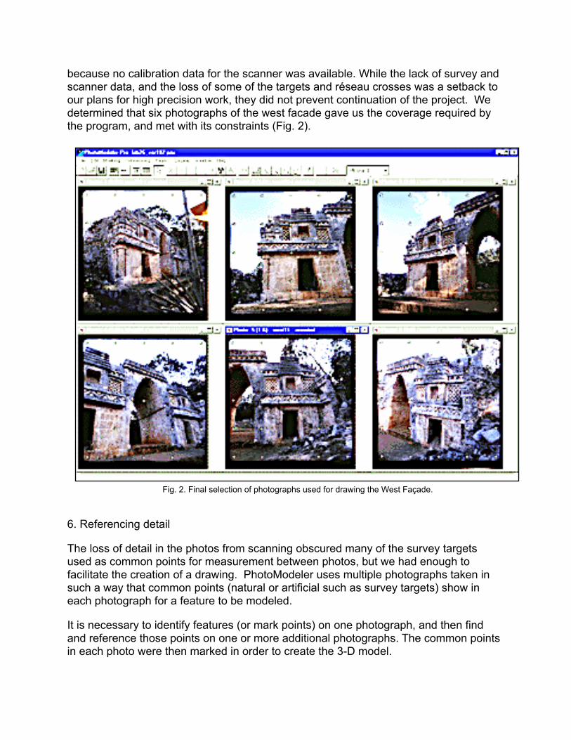
because no calibration data for the scanner was available. While the lack of survey and scanner data, and the loss of some of the targets and réseau crosses was a setback to our plans for high precision work, they did not prevent continuation of the project. We determined that six photographs of the west facade gave us the coverage required by the program, and met with its constraints (Fig. 2).
6. Referencing detail
The loss of detail in the photos from scanning obscured many of the survey targets used as common points for measurement between photos, but we had enough to facilitate the creation of a drawing. PhotoModeler uses multiple photographs taken in such a way that common points (natural or artificial such as survey targets) show in each photograph for a feature to be modeled.
It is necessary to identify features (or mark points) on one photograph, and then find and reference those points on one or more additional photographs. The common points in each photo were then marked in order to create the 3-D model.
Fig. 2. Final selection of photographs used for drawing the West Façade.
The identification and marking of common points on each photo is carried out as many times as necessary to determine the location of each point in three dimensions, and to minimize the total error. The PhotoModeler program has no way to knowing if points are marked incorrectly, and will therefore adjust the model to the information provided. By marking and referencing about 50 or so points, and then processing and auditing them, the chance of large errors propagating throughout the model is reduced. A point audit provides early feedback to the user on how well it is expected the adjustment will proceed. With poor data sets, it is possible that the adjustment will fail and no 3-D model will result. The audit stage helps weed out these cases.
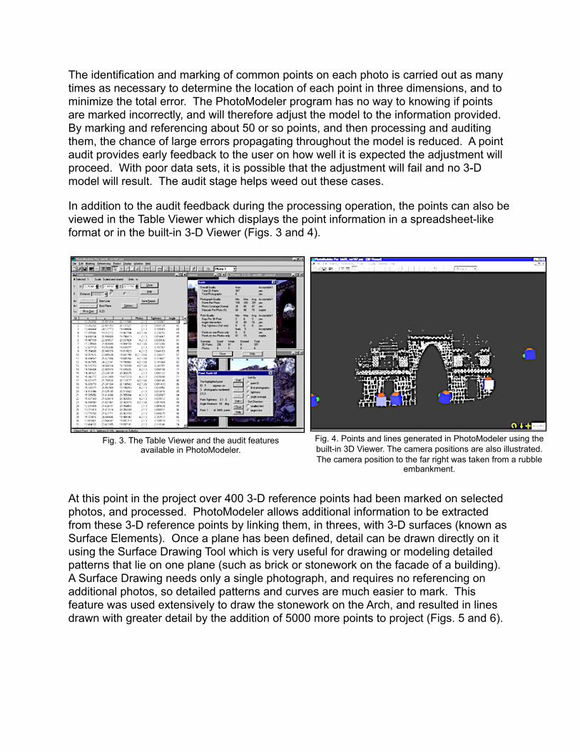
In addition to the audit feedback during the processing operation, the points can also be viewed in the Table Viewer which displays the point information in a spreadsheet-like format or in the built-in 3-D Viewer (Figs. 3 and 4).
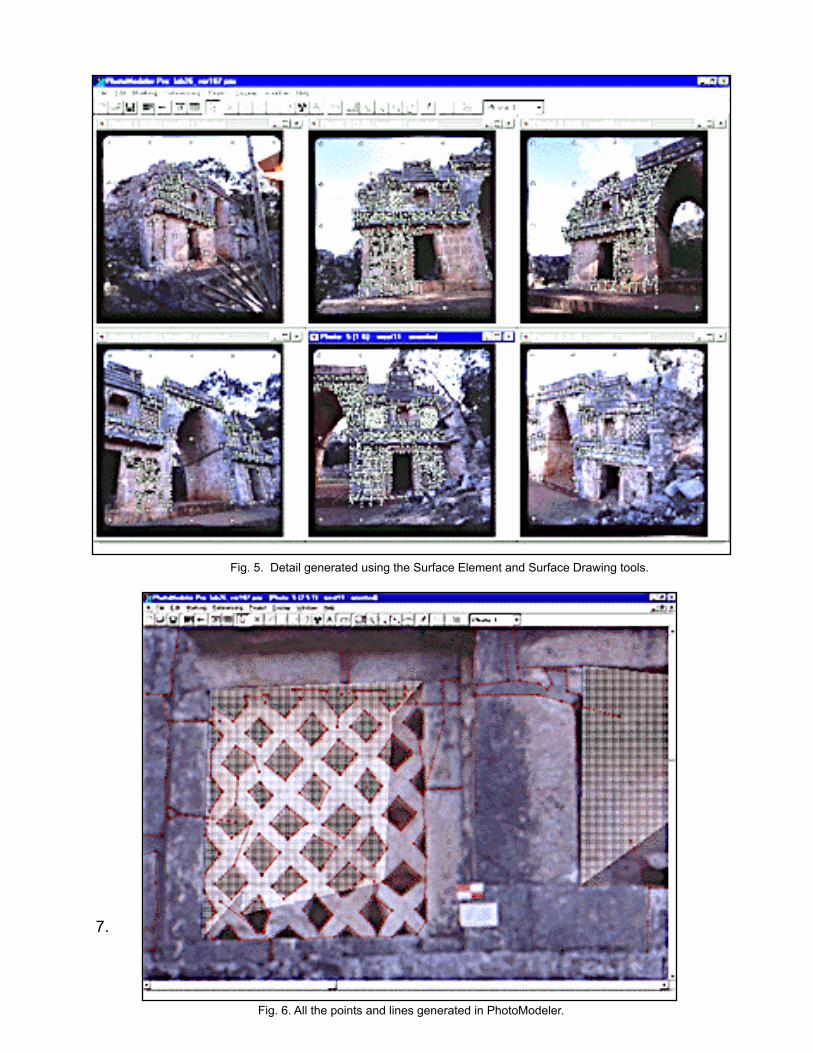
At this point in the project over 400 3-D reference points had been marked on selected photos, and processed. PhotoModeler allows additional information to be extracted from these 3-D reference points by linking them, in threes, with 3-D surfaces (known as Surface Elements). Once a plane has been defined, detail can be drawn directly on it using the Surface Drawing Tool which is very useful for drawing or modeling detailed patterns that lie on one plane (such as brick or stonework on the facade of a building). A Surface Drawing needs only a single photograph, and requires no referencing on additional photos, so detailed patterns and curves are much easier to mark. This feature was used extensively to draw the stonework on the Arch, and resulted in lines drawn with greater detail by the addition of 5000 more points to project (Figs. 5 and 6).
Fig. 3. The Table Viewer and the audit features available in PhotoModeler.
Fig. 4. Points and lines generated in PhotoModeler using the built-in 3D Viewer. The camera positions are also illustrated. The camera position to the far right was taken from a rubble
embankment.
7.
Fig. 5. Detail generated using the Surface Element and Surface Drawing tools.
Fig. 6. All the points and lines generated in PhotoModeler.
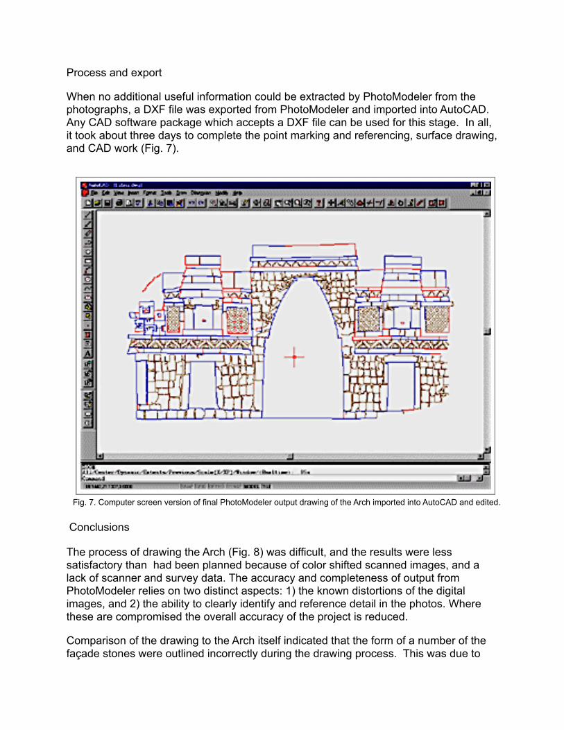
Process and export
When no additional useful information could be extracted by PhotoModeler from the photographs, a DXF file was exported from PhotoModeler and imported into AutoCAD. Any CAD software package which accepts a DXF file can be used for this stage. In all, it took about three days to complete the point marking and referencing, surface drawing, and CAD work (Fig. 7).
Conclusions
The process of drawing the Arch (Fig. 8) was difficult, and the results were less satisfactory than had been planned because of color shifted scanned images, and a lack of scanner and survey data. The accuracy and completeness of output from PhotoModeler relies on two distinct aspects: 1) the known distortions of the digital images, and 2) the ability to clearly identify and reference detail in the photos. Where these are compromised the overall accuracy of the project is reduced.
Comparison of the drawing to the Arch itself indicated that the form of a number of the façade stones were outlined incorrectly during the drawing process. This was due to
Fig. 7. Computer screen version of final PhotoModeler output drawing of the Arch imported into AutoCAD and edited.
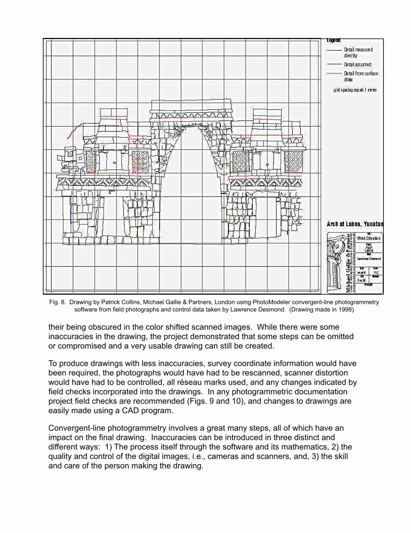
their being obscured in the color shifted scanned images. While there were some inaccuracies in the drawing, the project demonstrated that some steps can be omitted or compromised and a very usable drawing can still be created.
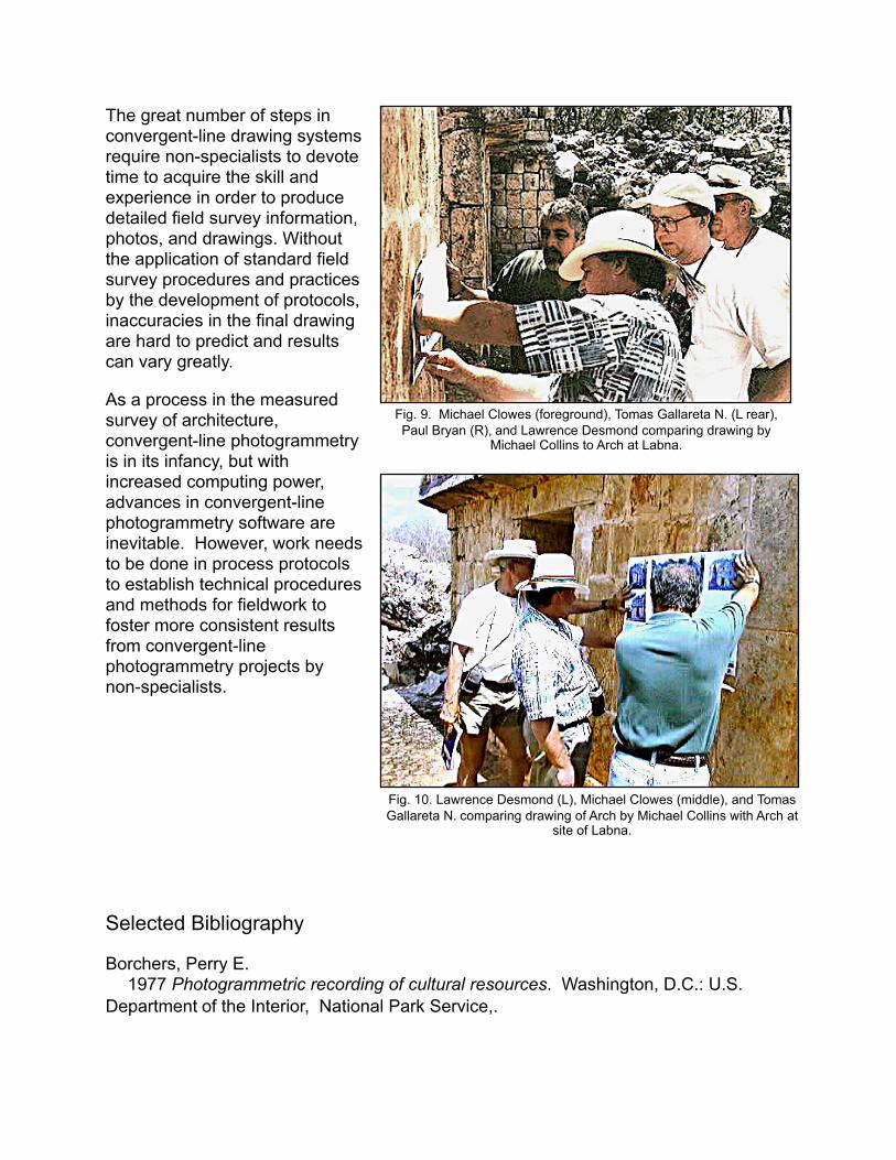
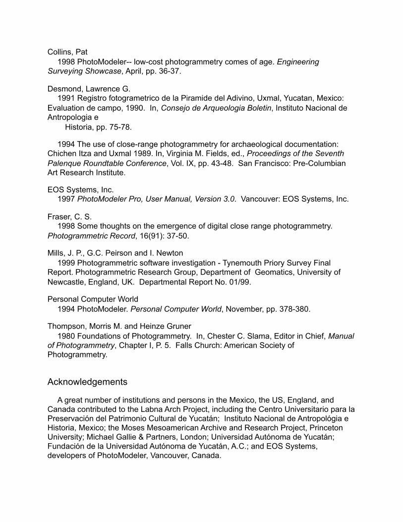
To produce drawings with less inaccuracies, survey coordinate information would have been required, the photographs would have had to be rescanned, scanner distortion would have had to be controlled, all réseau marks used, and any changes indicated by field checks incorporated into the drawings. In any photogrammetric documentation project field checks are recommended (Figs. 9 and 10), and changes to drawings are easily made using a CAD program.
Convergent-line photogrammetry involves a great many steps, all of which have an impact on the final drawing. Inaccuracies can be introduced in three distinct and different ways: 1) The process itself through the software and its mathematics, 2) the quality and control of the digital images, i.e., cameras and scanners, and, 3) the skill and care of the person making the drawing.
Fig. 8. Drawing by Patrick Collins, Michael Gallie & Partners, London using PhotoModeler convergent-line photogrammetry software from field photographs and control data taken by Lawrence Desmond. (Drawing made in 1998)
The great number of steps in convergent-line drawing systems require non-specialists to devote time to acquire the skill and experience in order to produce detailed field survey information, photos, and drawings. Without the application of standard field survey procedures and practices by the development of protocols, inaccuracies in the final drawing are hard to predict and results can vary greatly.
As a process in the measured survey of architecture, convergent-line photogrammetry is in its infancy, but with increased computing power, advances in convergent-line photogrammetry software are inevitable. However, work needs to be done in process protocols to establish technical procedures and methods for fieldwork to foster more consistent results from convergent-line photogrammetry projects by non-specialists.
Selected Bibliography
Borchers, Perry E. 1977 Photogrammetric recording of cultural resources. Washington, D.C.: U.S. Department of the Interior, National Park Service,.
Fig. 9. Michael Clowes (foreground), Tomas Gallareta N. (L rear), Paul Bryan (R), and Lawrence Desmond comparing drawing by
Michael Collins to Arch at Labna.
Fig. 10. Lawrence Desmond (L), Michael Clowes (middle), and Tomas Gallareta N. comparing drawing of Arch by Michael Collins with Arch at
site of Labna.
Collins, Pat 1998 PhotoModeler-- low-cost photogrammetry comes of age. Engineering Surveying Showcase, April, pp. 36-37.
Desmond, Lawrence G. 1991 Registro fotogrametrico de la Piramide del Adivino, Uxmal, Yucatan, Mexico: Evaluation de campo, 1990. In, Consejo de Arqueologia Boletin, Instituto Nacional de Antropologia e Historia, pp. 75-78.
1994 The use of close-range photogrammetry for archaeological documentation: Chichen Itza and Uxmal 1989. In, Virginia M. Fields, ed., Proceedings of the Seventh Palenque Roundtable Conference, Vol. IX, pp. 43-48. San Francisco: Pre-Columbian Art Research Institute.
EOS Systems, Inc. 1997 PhotoModeler Pro, User Manual, Version 3.0. Vancouver: EOS Systems, Inc.
Fraser, C. S. 1998 Some thoughts on the emergence of digital close range photogrammetry. Photogrammetric Record, 16(91): 37-50.
Mills, J. P., G.C. Peirson and I. Newton 1999 Photogrammetric software investigation - Tynemouth Priory Survey Final Report. Photogrammetric Research Group, Department of Geomatics, University of Newcastle, England, UK. Departmental Report No. 01/99.
Personal Computer World 1994 PhotoModeler. Personal Computer World, November, pp. 378-380.
Thompson, Morris M. and Heinze Gruner 1980 Foundations of Photogrammetry. In, Chester C. Slama, Editor in Chief, Manual of Photogrammetry, Chapter I, P. 5. Falls Church: American Society of Photogrammetry.
Acknowledgements
A great number of institutions and persons in the Mexico, the US, England, and Canada contributed to the Labna Arch Project, including the Centro Universitario para la Preservación del Patrimonio Cultural de Yucatán; Instituto Nacional de Antropológia e Historia, Mexico; the Moses Mesoamerican Archive and Research Project, Princeton University; Michael Gallie & Partners, London; Universidad Autónoma de Yucatán; Fundación de la Universidad Autónoma de Yucatán, A.C.; and EOS Systems, developers of PhotoModeler, Vancouver, Canada.

Specifically, we would like to thank the following for their important contributions to making the project a success: Arqlogo. Alfredo Barrera R., director, INAH Centro Yucatan; Dr. Raul Godoy Montañez, rector de la Universidad Autónoma de Yucatán; Ing. Roberto Centeno Lara, Facultad de Ingeniería, Universidad Autónoma de Yucatán; Antrop. Francisco Fernández Repetto, Facultad de Ciencias Antropológicas, Universidad Autónoma de Yucatán; Arq. Hernán Gómez Amaro, Facultad de Arquitectura, Universidad Autónoma de Yucatán, Mérida; Alan Walford, president of Eos Systems, Vancouver, Canadá; Erik Niemeyer, National Park Service, Sante Fe, New Mexico; Bart Anderson, professional writer; Ing. Mario Gómez Mejía, Facultad de Ingeniería, Universidad Autónoma de Yucatán; Antrop. Waldemaro Concha Vargas, Facultad de Ciencias Antropológicas, Universidad Autónoma de Yucatán; Arqlogo. Alberto Pérez Romero, Facultad de Ciencias Antropológicas, Universidad Autónoma de Yucatán; Br. Delfín Cocom Campos, Facultad de Ingeniería, Universidad Autónoma de Yucatán; and Ing. Alfredo Camara Zi, Facultad de Ingeniería, Universidad Autónoma de Yucatán.