2003.09.30 hazardous waste malfunction plan
TRANSCRIPT

INTERNATIONAL
Norlite Corporation Cohoes, New York
Startup, Shutdown, and Malfunction Plan Pursuant to the HWC MACT Regulations
Revision: 0
ENSR International September 30, 2003 Document No.: 09514-061-200
IOJ.-t\ OCT1 5

Nor1ite Corporation - Cohoes, NY - Startup Shutdown, and Malfunction Plan
TABLE OF CONTENTS
Revision: 0
Date: September 30, 2003
1. INTRODUCTION ............................................................................................................. 1-1
1.1 Program Objectives ....... .... ......... ....... .............. ..... ....... .... ......... .. ..... ...... .... .. ..... ..... 1-1
1.2 Organization of the Plan ................................. ........................... ......... .... ...... ......... 1-1
1.3 Regulatory Requirements ......... ............................................... ....................... ....... 1-2
1.4 Document Control/Plan Change Procedures ... ... ............. ........ ........... ..... ...... ........ 1-3
1.4.1 Revision Notification/Submittal Requirements ... ... ....... ............ ................. 1-3
1.4.2 Internal Document Control Procedures .......... ..................... ................ .. .. .. 1-4
1.4.3 Revision History ...... ........ ....................... ........... ... ......................... ........ .... 1-4
1.5 Facility Systems Descriptions ........ .......... ............. .................... ..... .................... .... 1-4
1.5.1 General Process Overview ........................ ......... ........................ .............. 1-4
1.5.2 Rotary Kilns Descriptions ............. .. ....................... .. ...................... .. ......... . 1-5
1. 5. 3 Feed System Descriptions .............................................. ....................... ... 1-5
1.5.4 Waste Handling and Blending Operations Description ...... ........................ 1-6
1.5.5 Procedures for Rapidly Stopping Hazardous Waste Feed During Equipment Malfunction .... ...................... ... ......... ... ........ ....................... .................................... 1-6
1.5.6 Air Pollution Control Equipment Description ......... ...... .... ....... ......... .......... 1-7
2. SSM PLAN FOR THE ROTARY KILNS .......................................................................... 2-1
2.1 Standard Operating Procedures for the Rotary Kilns ........................... ........ ......... . 2-1
2.1.1 Startup Procedures for the Rotary Kilns ....... ......... ............... .......... ........... 2-1
2.1.2 Shutdown Procedures for the Rotary Kilns .. ........... .......................... ........ 2-1
2.1.3 Malfunction Procedures for the Rotary Kilns ......... ..... ............ ......... .......... 2-1
2.2 SSM Plan Conformance Verification Procedures for the Rotary Kilns .................... 2-2
3. SSM PLAN FOR THE EMISSION CONTROL SYSTEMS ............................................... 3-1
3.1 Heat Exchanger ............................................ ..... ......... .. ..... .. .............. ....... ............. 3-1
C:IWINDOWS\Desktop\MACT\MACT Plans\Final Plans\Norlite SSMP Rev 0.doc

Norlite Corporation - Cohoes, NY - Startup Shutdown, and Malfunction Plan Revision: 0
Date: September 30, 2003
3.1.1 Standard Operating Procedures for the Heat Exchangers .. ...................... 3-1
3.1 .2 Malfunction Procedures for the Heat Exchangers ....... .. ............................ 3-1
3.2 Fabric Filter/Lime Addition (FF/LA) System .............. ............................................. 3-1
3.2.1 Standard Operating Procedures for the FF/LA System ............................. 3-1
3.2.2 Malfunction Procedures for the FF/LA System ........... ............................... 3-1
3.3 Wet Scrubber Systems ............... ........ .. ... .......... .......... .......................................... 3-2
3.3.1 Standard Operating Procedures for the Wet Scrubber Systems ............... 3-2
3.3.2 Malfunction Procedures for the Wet Scrubber Systems ............................ 3-2
3.4 SSM Plan Control Systems Emission Conformance Verification Procedures ... ...... 3-2
4. SSM PLAN FOR THE CMS ...................... ....................................................................... 4-1
4.1 SSM Plan for the Continuous Monitoring System (CMS) ....................................... 4-1
4.1.1 Standard Operating Procedures for the CMS .. .... ..................................... 4-1
4.1.2 Malfunction Procedures for the CMS ................................. ................... .... 4-1
4.2 SSM Plan for the Continuous Emissions Monitoring System (CEMS) ...... .. ........... . 4-1
4.2.1 Standard Operating Procedures for the CEMS ..... .......... .................... ...... 4-1
4.2.2 Malfunction Procedures for the CEMS .. ............. ................................... .. .. 4-2
4.3 SSM Plan Conformance Verification Procedures for the Process Monitoring and Continuous Emissions Monitoring Systems ........ .............................................. ............... 4-2
APPENDIX
Overview Process and Instrumentation Diagram
Air Pollution Control System Flow Diagram
SSM Checklist
C:\WINDOWS\Desktop\MACT\MACT Plans\Final Plans\Norlite SSMP Rev 0.doc

Norlite Corporation - Cohoes, NY - Startup Shutdown and Malfunction Plan
1. INTRODUCTION
1.1 Program Objectives
Revision : 0 Date: September 30, 2003
Section: 1.0 Page 1 of 10
As the operator of a facility which combusts hazardous waste, Norlite Corporation is required by the federal National Emission Standards for Hazardous Air Pollutant (NEHSAP) General Provisions at 40 CFR 63.6(e) to prepare and implement a Startup, Shutdown, and Malfunction Plan (SSMP) for the facility. This plan is intended to document the procedures the facility must take during periods of startup, shutdown, and malfunction in order to minimize releases of hazardous air pollutants (HAPs). In addition, the federal Hazardous Waste Combustor Maximum Achievable Control Technology (MACT) requires a SSMP, which serves as the means for the facility to ensure compliance with the MACT emission standards during periods of time when the equipment at the facility is running outside the bounds of normal system operation.
Under the NESHAP General Provisions, a period of excess emissions associated with a startup, shutdown, or malfunction is not considered a violation of the MACT standards if:
• The SSM event is described in a facility's SSMP, and
• During the event, the operators of the facility follow and document conformance with the procedures laid out in the Plan.
The primary purposes of the SSM Plan are:
• To ensure that MACT-affected sources are operated and maintained in a manner consistent with safety and good air pollution control practices for minimizing emission rates of HAPs during periods of equipment startup, shutdown, or malfunction,
• To correct process and emission control equipment malfunctions as soon as safe and practicable after their occurrence, and
• To streamline the reporting and recordkeeping obligations associated with periods of equipment startup, shutdown, or malfunction (including any corrective actions taken during periods of equipment malfunction).
1.2 Organization of the Plan
The procedures that operating personnel at Norlite follow during periods of startup, shutdown, and malfunction are integrated into the Standard Operating Procedures (SOPs) for each of the operating units at the facility. Controlled copies of the procedures and schedules referenced in
C:\WINDOWS\Desktop\MACT\MACT Plans\Final Plans\Norlite SSMP Rev 0.doc

Norlite Corporation - Cohoes, NY - Startup Shutdown and Malfunction Plan
Revision: 0
Date: September 30, 2003 Section: 1.0
Page 2 of 10
this Plan will be located in each Kiln Control Room, Kiln Supervisors Office and in the office library.
The SSMP is organized as follows: Section 1 provides an overview of the Plan, as well as the specific regulatory citations which govern it's preparation and implementation. Section 1 also contains a description of the Norlite facility. Section 2 provides reference to the appropriate Startup, Shutdown, and Malfunction procedures for the Lightweight Aggregate Kiln, Section 3 provides references to the appropriate SSM procedures for the facility's emission control systems, and Section 4 provides references to the appropriate SSM procedures for the facility's continuous monitoring systems, including both operating parameter and continuous emissions monitoring.
1.3 Regulatory Requirements
Norlite is subject to MACT standards for Hazardous Waste Combustors (HWCs), codified commencing at 40 CFR 63.1200. These standards include the obligation to prepare a SSMP for the facility (40 CFR 63.1206(c)(2)).
The General Provisions section of the NESHAP rule lays out administrative procedures, compliance demonstration requirements, and other obligations for sources subject to MACT standards promulgated under the Federal air regulations in 40 CFR Part 63. These provisions, adopted on March 16, 1994, include a requirement that the owner or operator of a source subject to a MACT standard develop and implement a plan which describes the procedures to be followed for operating and maintaining the source during periods of startup, shutdown, and malfunction (40 CFR 63.6(e){3)). The NESHAPs General Provisions require that the SSMP be in place prior to a source's MACT compliance deadline. The SSMP is not required to be reviewed and approved by regulatory agencies prior to it's implementation, however, a copy must be submitted if it is requested by the permitting authority.
As described in the previous section, the SSMP must describe how process and HAP emission control systems will be operated so as to minimize HAP emissions during periods of startup, shutdown, and malfunction. When actions taken during a startup, shutdown, or malfunction event (including actions taken to correct a malfunction) are consistent with procedures specified in the Plan, then any HAP emissions in excess of the MACT requirements which occur are considered periods of "excess emissions" rather than violations of the standard. Consequently, the owner or operator of the source must keep records to demonstrate that the facility's Plan was followed during such events. A semi-annual report is required to be submitted certifying that the Plan was followed if a startup, shutdown, or malfunction event occurred during the reporting period.
If the actions taken during a startup, shutdown, or malfunction event are inconsistent with the Plan, and the event results in an emission or operating parameter limit being exceeded, the
C:\WINDOWS\Desktop\MACnMACT Plans\Final Plans\Nortite SSMP Rev 0.doc

Norlite Corporation - Cohoes, NY - Startup Shutdown and Malfunction Plan
Revision: 0 Date: September 30, 2003
Section: 1.0 Page 3 of 10
owner or operator must record the actual actions taken and meet certain other reporting and Plan update requirements. Within two working days of the action, verbal notification (telephone or in-person) is required, and within seven working days a written report is required to be submitted to the Agency containing an explanation of the circumstances, the reasons why the SSMP was not followed, and the excess emissions and/or monitoring exceedances that occurred .
If a malfunction event occurs which causes emissions in excess of the standard that is not addressed, or inadequately addressed, by the SSMP, the Plan must be revised within 45 days to address the malfunction, in order for the malfunction event to be accorded the same treatment as events covered by the original Plan. The revised plan must include detailed procedures that will be followed to minimize emissions during similar future events, as well as a program of corrective action for similar malfunctions (see 40 CFR 63.6(e)(3)(viii)).
The HWC MACT Standards provide three alternative pathways for facilities to follow to develop their SSMP with respect to treatment of malfunctions. Because none of Norlite's existing RCRA Permit Conditions are in conflict with the treatment afforded by the MACT for malfunctions that are described in this Plan, Norlite has elected to leave these permit conditions unchanged and is therefore following neither the RCRA Option (as described at 40 CFR 270.235(a)(2)) nor the Clean Air Act Option (as described at 40 CFR 63.1206(c)(2)(ii )).
1.4 Document Control/Plan Change Procedures
1.4.1 Revision Notification/Submittal Requirements
The NESHAP General Provisions at 40 CFR 63.6(e)(3)(vii) describe how the SSMP may be required to be revised based on any of the following criteria:
• If it does not address an SSM event that has occurred,
• If its procedures do not adequately provide for minimization of emissions during an SSM event,
• If it does not provide adequate procedures for correction of a malfunction as quickly as possible,
• If it includes an event that does not meet the definition of startup, shutdown, or malfunction, or
• If changes are made to the facility equipment or operations that impact the SSMP.
C:\WINDOWS\Desktop\MACT\MACT Plans\Final Plans\Norlite SSMP Rev 0.doc

Norlite Corporation - Cohoes, NY - Startup Shutdown and Malfunction Plan
Revision : 0 Date: September 30, 2003
Section: 1.0 Page4 of 10
If an SSM event occurs that is not addressed or is inadequately addressed by the SSMP and causes excess emissions, the required notification provisions described previously in Section 1.3 of this Plan are triggered (i.e., verbal notification to the regulatory agency as per SOP SSMP 1-03 within two working days, followed by written confirmation within seven days). In addition, the Plan must be revised within 45 days after the event in order for the event to be treated the same as events in the original Plan.
Once the Plan has been revised, the superseded revision must be kept on record and made available for inspection upon request for a period of 5 years.
If the Plan is revised in such a way that it changes the scope of activities at the facility which are deemed to be a startup, shutdown or malfunction event, or if the revision otherwise modifies the applicability of an emission limit, written notice to the regulatory agency describing the revision must be made before the revised Plan can be considered to have gone into effect.
1.4.2 Internal Document Control Procedures
Standard operating procedure SSMP 1-02 (Document Control Log, Document Control File) contains Norlite's procedures for tracking and controlling internal documentation. Original issuance of and control of revisions to the SSMP are subject to these procedures.
1.4.3 Revision History
This Plan was prepared and issued as Revision O on September 30, 2003.
1.5 Facility Systems Descriptions
This section presents a summary description of the Norlite process and combustion system. An overview process and instrumentation diagram (P&ID) is provided in the Appendix A (Drawing 1 ).
1.5.1 General Process Overview
The Norlite facility produces an expanded shale lightweight aggregate in two dry process rotary kilns. Raw materials are quarried on-site and transported to the kiln via a conveyor system. The basic material (shale) is proportioned and stored in a silo. The raw product is introduced to the kiln at the feed (back) end from the silo, while fuels are fed from the opposite end. Calcination of the product occurs at a product temperature of 1,700°F to 2,000°F. The shale is then heated to the point of incipient fusion where it is in a semi-plastic state to expand internal gases, thereby creating voids. The cooled vitreous clinker is then discharged and stockpiled.
C:\WINDOWS\Desktop\MACT\MACT Plans\Final Plans\Norlite SSMP Rev 0.doc

Norlite Corporation - Cohoes, NY - Startup Shutdown and Malfunction Plan
1.5.2 Rotary Kilns Descriptions
Revision: 0 Date: September 30, 2003
Section: 1.0
Page 5 of 10
Kiln No. 1, manufactured by Traylor, is 175 feet long. Kiln No. 2, manufactured by AllisChalmers, is 180 feet long. Both kilns have an outside diameter of 11 feet and consist of a steel shell lined with 6-inches of refractory brick, for an effective inside diameter of 10 feet. The burn zone extends approximately 30 feet from the front end of the kiln. The burn zone gas
temperature is maintained at 2,200°F to 3,000°F. Each kiln has thermocouples mounted at the kiln gas exit and at the fabric filter inlet for monitoring process temperatures.
The rated capacity of each kiln is approximately 25 tons per hour (tph) clinker. Typically, 2.5 x 10⁶ Btu are required to produce one ton of clinker at maximum capacity. In order to achieve a quality lightweight aggregate product, the kiln is normally operated at approximately 8% to 10% oxygen at the back-end with carbon monoxide concentrations less than 100 ppm.
1.5.3 Feed System Descriptions
Heat is supplied to each kiln by firing fossil fuel, used oil , or liquid low grade fuel (LLGF). All fuel is fed to the kiln through burners at the front end of the kiln.
Liquid Waste Feeds - LLGF is maintained in nitrogen blanketed storage tanks and is delivered to the kiln via pumps to maintain an approximate maximum feed rate of 13.3 gallons per minute (gpm) to each burner. The burner consists of a stainless steel outer pipe that supplies atomization air or steam and a 3/ 8-inch diameter carbon steel inner pipe. This burner uses highpressure air or steam atomization to inject the material directly into the combustion zone. The LLGF burner is rated at 20.0 gpm at 35 psi line pressure and is monitored continuously with a Micromotion doppler flow meter.
Solid Feed Materials - The basic feed material is shale, which is proportioned and stored in a covered silo and then fed directly to the kiln. The shale is introduced at the back end of the kiln. No other solid waste materials are fed to the kiln.
Process Vent Streams - There are two (2) process vent streams that are sent to the kiln for incineration. The first stream is the vent from the nitrogen blanketed LLGF storage tanks. During the filling cycles of the storage tanks, any excess gaseous vapors are vented through a closed loop system to the burner end of the kiln. The second stream consists of vented material from the drum handling operations. Drums are emptied via a vacuum system. The vacuum system vents to the kiln and also vapors from the drum processing room, under negative ventilation. This vent stream is mixed with ambient air and is used as primary combustion air for the burner.
Supplemental Fuels - Fossil fuels or used oil are used to preheat the kiln during start-up and may also be used as supplemental fuel while firing LLGF. Fossil fuels or used oil may also be used as a pilot when firing LLGF. Fuel oil or used oil may also be blended with LLGF when
C:\WINDOWS\Desktop\MACT\MACT Plans\Final Plans\Norlite SSMP Rev 0.doc

Nortite Corporation - Cohoes, NY - Startup Shutdown and Malfunction Plan
Revision: 0 Date: September 30, 2003
Section: 1.0 Page 6 of 10
firing to increase heat content of the waste feed and improve combustion characteristics. In cases where fuel oil or used oil is fired with LLGF, the metals content of the fuel oil and used oil is taken into account in demonstrating compliance with condition Vll(C)(4) of the facility's Part 373 Permit.
1.5.4 Waste Handling and Blending Operations Description
LLGF typically has a flash point of 200°F or lower. The LLGF is not reactive, but may be a hazardous waste as defined in New York State regulations because the heavy metal and organic compound concentrations may exceed limits. Also, LLGF may contain a characteristic corrosive waste.
Norlite stores the LLGF in storage tanks or in drums within the bulk storage area. The tanks and containers are located in a permitted secondary containment. The design and operation for the tanks and containers are described in Section D, Section F (under Inspection), and Section G -- the Emergency and Contingency Plan, of the RCRA Part 373 permit. The LLGF, having been pre-screened, is non-corrosive to the glass-lined (Tanks 300-600), carbon steel (Tanks 100 A,B,C and 200 B,C) or stainless steel (Tank 200 A) storage tanks designed with suitable corrosion allowance. The necessary specification for the fuel has been provided to the suppliers, and has been confirmed with their LLGF Specification Sheet, and with the Norlite analysis provided prior to burning and unloading.
When preparing a tank of LLGF for burning, Norlite determines the heating value of the fuel along with the concentration of metals and total halogens. This is accomplished by 1) calculation based upon the original analysis of the fuel that makes up the tank, or 2) sampling and analysis of the tank. Each load of LLGF is sampled and analyzed upon receipt as described in Section C-5(b) of the Part 373 permit. A control procedure prevents the burning of any waste until the heat content, total halogen, PCB, and metal parameters have been verified. An analysis form (WAP-2) is completed for each tank burned indicating the analyzed or calculated values for each permit parameter, the dates of analysis and/or calculation, and the date of authorization to burn the waste from the designated tank. The tank is not cleared for burning until all regulated constituents are verified and shown to be within permit limits. Once the tanks have been certified, the tanks are locked with pad locks on the bottom and top valves and the recirculation valve in accordance with SOP OM 2-02. The volume of the tanks are measured using either ultrasonic or radar level gauges.
1.5.5 Procedures for Rapidly Stopping Hazardous Waste Feed During Equipment Malfunction
Each kiln is manned on an around-the-clock basis by the burner operator from the kiln control room. The burner operator can monitor critical operating variables from the control room via a
C:\WINDOWS\Desktop\MACnMACT Plans\Final Plans\Norlite SSMP Rev 0.doc

Norlite Corporation - Cohoes, NY - Startup Shutdown and Malfunction Plan
Revision: 0
Date: September 30, 2003 Section: 1.0
Page 7 of 10
computerized data acquisition system (DAS). The burner operator, in conjunction with the kiln field operator and mechanic, make routine system adjustments to maintain the kiln at optimum conditions for the production of light weight aggregate while maintaining the system within the operating window as set forth by the automatic waste feed cutoff (AWFCO) system.
In the event that an AWFCO operating parameter exceeds the operating window, LLGF is automatically cutoff by the AWFCO system. In this event, the burner operator will switch to a fossil fuel or oil until corrections have been made to bring the operation within the operating window.
In the event of a power failure, all systems shut down including, but not limited to, LLGF flow, fuel farm feed systems, raw shale feed, main flame, etc. All systems require manual restart. A fossil fuel is fired to bring all operating parameters within the operating window prior to commencing LLGF feed.
The main flame of the kiln is either self-sustaining or sustained by the presence of a fossil fuel pilot. Both the main flame and the pilot flame are monitored by an electronic eye to provide positive proof that a flame exists. In the event of a loss of signal by the electronic eye, the fossil fuel feed to the pilot, the main natural gas valve, the LLGF AWFCO valve, and the used oil feed valve are closed and a manual reset is required to re-establish a proof positive flame. Should operating parameters fall outside the operating window during a flame failure , a fossil fuel is fired to bring all operating parameters within the operating window prior to commencing LLGF feed.
1.5.6 Air Pollution Control Equipment Description
Both kilns have identical emission control systems, as depicted in Drawing 2 in Appendix A The systems include both wet and dry emission control devices for the collection and removal of particulate matter, hydrogen chloride (HCI), metals and other gaseous emission products. The principal collection mechanisms are sedimentation, condensation, impaction, filtration and interception for particulate matter and metals and absorption for HCI and other gaseous species. The overall Air Pollution Control System (APCS) also includes forced draft fans, an induced draft fan and exhaust stack, each of which is described below.
Multiclone - Kiln emissions first pass through a mechanical collector to remove large particulate matter, a Barrens multiple cyclone unit (multiclone) incorporating relatively small diameter cyclones operating in parallel with a common inlet and outlet. The multiclone is provided to remove coarse particulate matter and is rated for 2-3 in. w.c. pressure drop. Dust collected in the multi-clone accumulates in a hopper. It is pneumatically conveyed and combined with the baghouse fines, which are added to the light weight aggregate becoming part of the product.
C:\WINDOWSIOesktop\MACn MACT Plans\Final Plans\Norlite SSMP Rev 0.doc

Norlite Corporation - Cohoes, NY - Startup Shutdown and Malfunction Plan
Revision: 0
Date: September 30, 2003 Section: 1.0
Page 8 of 10
Heat Exchanger - The kiln flue gas then passes through an air to air heat exchanger rated at 65,000 acfm. This unit was redesigned in late 1999/early 2000 and now uses two (2) forced draft fans for providing ambient air as the cooling medium. Gases enter the heat exchanger at
approximately 900°F to 1, 100°F and exit at 400 - 460°F with a 2-3 inch w.c. pressure drop
across the unit. The gases are cooled to 400°F or lower, by the injection of quench air to the flue gas at the exchanger outlet. A fan supplies air to the bottom exchanger shell and a second fan supplies ambient air directly to the top exchanger shell. A damper provides cooling air to control temperature if the inlet temperature to the baghouse is higher than desired. The damper is under negative pressure since it is upstream of the induced draft fan. The damper does not function as an emergency bypass to the air pollution control system. There is no such bypass or "dump stack" in the entire kiln process.
Fabric Filter with Hydrated Lime Addition - Following the heat exchanger is an Aeropulse, Inc. Power Pulse Collector (fabric filter or baghouse) with three modules and 17,334 square feet
of filter area. The unit is rated for 52,700 acfm at 450°F. The air cloth ratio is 3.04:1 with all three modules operating and 4.50:1 with one down for maintenance. Teflon impregnated woven fiberglass with a permeability of approximately 10 cfm per square foot at 0.5 in. w.c. is used as the filter media. The filter media is continuously pulsed one row at a time, controlled by a timer. A modulating air damper automatically adjusts inlet gas temperatures (if required) to less than
400°F by bleeding in ambient air directly into the flue gas before entering the baghouse. An
automatic waste feed cutoff is activated if baghouse inlet temperature exceeds 400°F, since this is the Part 373 Permit limit. Pressure drop across the unit is rated between 2-10 in. w.c., with all three modules on-line.
Hydrated lime [Ca(OH)z], stored in a 2,500 cubic foot silo, is injected into the air pollution control system immediately prior to the baghouse. This is primarily to control sulfur dioxide and sulfuric acid mist from the combustion of LLGF in the kiln and to protect the baghouse from resulting corrosion. The lime also neutralizes hydrogen chloride, providing approximately 80% of the removal prior to the wet scrubber. The baghouse is designed to control 60% of the S02 and S03 introduced from the kiln. Lime feed varies from near zero to 500 pounds per hour, depending upon the fuel type and feed rate.
Fines collected in each cell of the baghouse are discharged via a rotary air lock. The fines are pneumatically conveyed and combined with the multiclone fines to one of two storage silos. Fines from both silos are added to the light weight aggregate, becoming part of the product.
Venturi Scrubber - The ID fan carries exhaust gases to a BECO Venturi (MMV) scrubber for
acid gas removal. This unit is rated for 53,000 acfm at 450°F at the inlet and 38,600 acfm at
138°F at the outlet, with 2 to 6 in. w.c. pressure drop. The scrubber is a rod design that has tubular stainless steel rods and baffles installed in rows across the throat. The intent is to provide high turbulence like the effect of a small venturi throat without incurring the high
C:\WINDOWS\Desktop\MACT\MACT Plans\Final Plans\Norlile SSMP Rev 0.doc

Norlite Corporation - Cohoes, NY - Startup Shutdown and Malfunction Plan
Revision: 0 Date: September 30, 2003
Section: 1.0
Page 9 of 10
pressure drop typically associated with conventional high efficiency venturi scrubbers. Additionally, the tubes and baffles provide additional impaction surfaces for enhanced particulate and HCI collection. The scrubber is designed for 99% HCI and 68% SO2 removal efficiencies.
Clean water headers are located directly above the venturi to provide sensible cooling to the exhaust system. Caustic sodium carbonate (soda ash) or sodium hydroxide solution, comprised of a maximum of 10% dissolved solids (sodium carbonate, sodium chloride and/or sodium sulfate), is recycled through the unit at approximately 200 gpm. It is introduced through nozzles located below the water headers and directly above the MMV module. Scrubbing solution is also injected into the transition segment located between the venturi MMV and Ducon units.
Excess water drains from the venturi exit elbow to the 1,000-gallon settling/recycle tank. The pH of the solution in the recycle tank is continuously monitored by a pH probe and automatically maintained at pH 7.9 or greater. The pH is adjusted by the introduction of 5% to 10% sodium carbonate or sodium hydroxide solution to the venturi feed at a typical rate of 3 to 25 gpm depending on actual pH readings. Slowdown is taken from the blowdown pump discharge to maintain a constant solids concentration in the solution. Slowdown is typically in the range of 13.0 to 30.0 gpm, depending on the quantity of fuel burned as well as the chloride and sulfur contents.
Ducon Mist Eliminator - Following the BECO MMV unit is a BECO/QUAD MMV mist eliminator installed in the bottom of the Ducon unit. The unit is designed to capture entrained droplets of caustic solution exiting the BECO scrubber. This unit is rated for a pressure drop of 1.5 to 4 in. w.c. This mist eliminator drains into the recycle tank.
A further modification of the Ducon unit consists of two plastic mesh AUTO YORKTM mist eliminator pads (or the equivalent) segmented by a baffle controlling velocity across each pad face. This mist eliminator is located at the top of the unit immediately preceding the exhaust stack. Water sprays on the pad flush solids into the unit for capture in the bottom. The Ducon unit functions as an entrainment separator for the venturi scrubber.
Induced and Forced Draft Fans - The baghouse is followed by a Barron 400 HP system fan which induces draft through the kiln , multiclone, heat exchanger and baghouse and provides forced draft on the exhaust gases through the venturi scrubber and Ducan mist elimination units. Additionally, the fan provides induced draft for a hood installed over the kiln shale feed chute, designed and installed to capture any fugitive emissions emanating from this area. The ID fan is rated at 53,000 acfm at 450°F.
Secondary combustion air is supplied by forced draft clinker cooler fans rated at a total of 25,000 scfm. The secondary combustion air is preheated by the clinker cooler at the front end of the kiln.
C:\WINDOWS\Desktop\MACT\MACT Plans\Final Plans\Norlite SSMP Rev 0.doc

Nor1ite Corporation - Cohoes, NY - Startup Shutdown and Malfunction Plan
Revision: 0
Date: September 30, 2003 Section: 1.0
Page 10 of 10
Exhaust Stack - Scrubbed kiln exhaust passes to the atmosphere via a 48 inch diameter fiberglass-reinforced plastic (FRP) stack 120 feet above grade at approximately 46,000 acfm at
130°F and 15% moisture (v/v). Two access platforms are provided for stack sampling.
C:IWINDOWS\Desktop\MACT\MACT Plans\Final Plans\Norlite SSMP Rev 0.doc

Nortite Corporation - Cohoes, NY - Startup Shutdown and Malfunction Plan
2. SSM PLAN FOR THE ROTARY KILNS
2.1 Standard Operating Procedures for the Rotary Kilns
2.1.1 Startup Procedures for the Rotary Kilns
Revision: 0 Date: September 30, 2003
Section: 2.0 Page 1 of 2
Operating procedures for startup of the Norlite rotary kilns, including procedures to minimize emissions of HAPs during startup events, are contained in the following standard operating procedures:
• SSMP 2-01: Startup of the Kilns From a Cold Condition
• SSMP 2-02: Restart of the Kilns From a Warm Condition
2.1.2 Shutdown Procedures for the Rotary Kilns
Operating procedures for shut down of the Norlite rotary kilns, including procedures to minimize emissions of HAPs during shut down events, are contained in the following standard operating procedures:
• SSMP 2-03: Planned or Routine Shutdown of the Kilns
• SSMP 2-03A: Emergency or Unexpected Shutdown of the Kilns
2.1 .3 Malfunction Procedures for the Rotary Kilns
Procedures to be followed during malfunction events, including procedures to minimize emissions of hazardous air pollutants during these events, are contained in the following standard operating procedures:
• SSMP 2-04: Procedures for Deviation from Minimum Kiln Backend Temperature
• SSMP 2-05: Procedures for Exceedance of Maximum Baghouse Inlet Temperature
• SSMP 2-06: Procedures for Exceedance of Maximum Flue Gas Flow Rate
• SSMP 2-07: Procedures for Deviation from Minimum Venturi Pressure Drop
• SSMP 2-08: Procedures for Deviation from Minimum Scrubber Slowdown Rate
C:\WINDOWS\Desktop\MACnMACT Plans\Final Plans\Norlile SSMP Rev 0.doc

Norlite Corporation - Cohoes, NY - Startup Shutdown and Malfunction Plan
Revision: 0 Date: September 30, 2003
Section: 2.0
Page 2 of 2
• SSMP 2-09: Procedures for Deviation from Minimum Scrubber Tank Liquid Level
• SSMP 2-10: Procedures for Deviation from Minimum Scrubber Recirculation Rate
• SSMP 2-11: Procedures for Deviation from Minimum Scrubber Liquid pH
• SSMP 2-12: Procedures for Deviation from Minimum Dry Sorbent Feed Rate
• SSMP 2-13: Procedures for Deviation from Minimum Dry Sorbent Carrier Fluid Flow Rate
• SSMP 2-14: Procedures for Deviation from Negative Kiln Pressure
• SSMP 2-15: Procedures for Exceedance of Carbon Monoxide Emission Concentration
• SSMP 2-17: Procedures to Follow During a Power Failure
• SSMP 2-18: Procedures to Follow for Loss of ID Fan
• SSMP 2-19: Procedures to Follow for Loss of Dilution Damper
• SSMP 2-20: Procedures to Follow for Loss of LGF Flow
• SSMP 2-21 : Procedures to Follow for Loss of Shale Feed
2.2 SSM Plan Conformance Verification Procedures for the Rotary Kilns
Norlite Field Operators will utilize a paper checklist (SSMP 3-04A: Field Operators MACT Checklist - Form) to document conformance with SSM Plan procedures. This checklist will record that the appropriate procedures were followed for each startup, shutdown, or malfunction event by checking that each action item was completed. Copies of the checklists completed for each startup, shutdown, or malfunction event will be maintained by the facility.
C:\WINDOWS\Desktop\MACT\MACT Plans\Final Plans\Norlite SSMP Rev 0.doc
Norlite Corporation - Cohoes, NY - Startup Shutdown and Malfunction Plan
Revision: 0
Date: September 30, 2003 Section: 3.0
Page 1 of 2
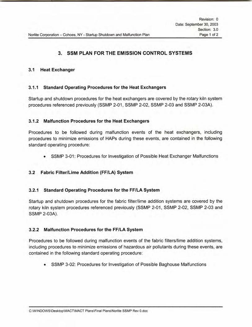
3. SSM PLAN FOR THE EMISSION CONTROL SYSTEMS
3.1 Heat Exchanger
3.1.1 Standard Operating Procedures for the Heat Exchangers
Startup and shutdown procedures for the heat exchangers are covered by the rotary kiln system procedures referenced previously (SSMP 2-01, SSMP 2-02, SSMP 2-03 and SSMP 2-03A).
3.1.2 Malfunction Procedures for the Heat Exchangers
Procedures to be followed during malfunction events of the heat exchangers, including procedures to minimize emissions of HAPs during these events, are contained in the following standard operating procedure:
• SSMP 3-01 : Procedures for Investigation of Possible Heat Exchanger Malfunctions
3.2 Fabric Filter/Lime Addition (FF/LA) System
3.2.1 Standard Operating Procedures for the FF/LA System
Startup and shutdown procedures for the fabric filter/lime addition systems are covered by the rotary kiln system procedures referenced previously (SSMP 2-01, SSMP 2-02, SSMP 2-03 and SSMP 2-03A).
3.2.2 Malfunction Procedures for the FF/LA System
Procedures to be followed during malfunction events of the fabric filters/lime addition systems, including procedures to minimize emissions of hazardous air pollutants during these events, are contained in the following standard operating procedure:
• SSMP 3-02: Procedures for Investigation of Possible Baghouse Malfunctions
C:\WINDOWS\Desktop\MACT\MACT Plans\Final Plans\Norlite SSMP Rev 0.doc

Norlite Corporation - Cohoes, NY - Startup Shutdown and Malfunction Plan
3.3 Wet Scrubber Systems
Revision: 0
Date: September 30, 2003
Section: 3.0 Page 2 of 2
3.3.1 Standard Operating Procedures for the Wet Scrubber Systems
Startup and shutdown procedures for the wet scrubber systems are covered by the rotary kiln system procedures referenced previously (SSMP 2-01. SSMP 2-02, SSMP 2-03 and SSMP 2-03A).
3.3.2 Malfunction Procedures for the Wet Scrubber Systems
Procedures to be followed during malfunction events of the wet scrubber systems, including procedures to minimize emissions of hazardous air pollutants during these events. are contained in the following standard operating procedure:
• SSMP 3-03: Procedures for Investigation of Possible Malfunction of the Ducan and Venturi Scrubber Systems
3.4 SSM Plan Conformance Verification Procedures for the Emission Control Systems
Norlite Field Operators will utilize a paper checklist (SSMP 3-04A: Field Operators MACT Checklist - Form) to document conformance with SSMP procedures. This checklist will record that the appropriate procedures were followed for each startup, shutdown, or malfunction event by checking that each action item was completed. Copies of the checklists completed for each startup, shutdown, or malfunction event will be maintained by the facility.
C:\WINDOWS\Desktop\MACT\MACT Plans\Final Plans\Norlite SSMP Rev 0.doc

Norlite Corporation - Cohoes, NY - Startup Shutdown and Malfunction Plan
4. SSM PLAN FOR THE CMS
4.1 SSM Plan for the Continuous Monitoring System (CMS)
4.1.1 Standard Operating Procedures for the CMS
Revision: 0 Date: September 30, 2003
Section: 4.0 Page 1 of 2
The facility process monitoring systems can be operated independently of the rotary kiln and emission control systems. Procedures referenced previously (SSMP 2-01, SSMP 2-02, SSMP 2-03 and SSMP 2-03A) describe startup and shutdown of the rotary kiln systems. The CMS are kept running even when the kilns are down.
4.1.2 Malfunction Procedures for the CMS
Malfunctions of process monitoring systems are among the possible causes of malfunctions in both the rotary kiln systems and emission control systems. Standard operating procedures referenced previously describe actions that operating personnel are to follow to investigate malfunctions of these systems. Standard operating procedures SSMP 2-04 to SSMP 2-17 cover malfunctions of the rotary kiln systems; standard operating procedures SSMP 3-01 to SSMP 3-03 cover the malfunctions of the emission control systems.
4.2 SSM Plan for the Continuous Emissions Monitoring System (CEMS)
4.2.1 Standard Operating Procedures for the CEMS
The continuous emissions monitoring systems can be operated independently of the rotary kiln systems. Startup procedures for the continuous emissions monitoring systems are contained in the following standard operating procedure:
• SSMP 4-01 : Startup of Continuous Emissions Monitoring Systems
The continuous emissions monitoring systems are intended to be operated on a continuous basis and not shut down, as reflected in the following standard operating procedure:
• SSMP 4-04: Shutdown of Continuous Emissions Monitoring Systems
C:\WIN0OWS\0esktop\MACT\MACT Plans\Final Plans\Norlite SSMP Rev 0.doc

Norlite Corporation - Cohoes, NY - Startup Shutdown and Malfunction Plan
4.2.2 Malfunction Procedures for the CEMS
Revision: 0 Date: September 30, 2003
Section: 4.0
Page 2 of 2
Procedures to be followed during malfunction events of the continuous emissions monitoring systems, including procedures to minimize emissions of hazardous air pollutants during these events, are contained in the following standard operating procedures:
• SSMP 4-02: Procedures for Power Failure of the Continuous Emissions Monitoring Systems
• SSMP 4-03: Procedures for Malfunctions of the Continuous Emissions Monitoring Systems
4.3 SSM Plan Conformance Verification Procedures for the Process Monitoring and
Continuous Emissions Monitoring Systems
Norlite Field Operators will utilize a paper checklist (SSMP 3-04A: Field Operators MACT Checklist - Form) to document conformance with SSM Plan procedures. This checklist will record that the appropriate procedures were followed for each startup, shutdown, or malfunction event by checking that each action item was completed . Copies of the checklists completed for each startup, shutdown, or malfunction event will be maintained by the facility.
C:IWINDOWS\Desktop\MACT\MACT Plans\Final Plans\Norlite SSMP Rev 0.doc

Norlite Corporation - Cohoes, NY - Startup Shutdown and Malfunction Plan
Appendix:
Revision: 0
Date: September 30, 2003 Appendix
Page 1 of 3
Overview Process and Instrumentation Diagram
Air Pollution Control System Flow Diagram
SSM Checklist
C:\WINDOWS\Desktop\MACnMACT Plans\Final Plans\Norlite SSMP Rev 0.doc

r I I I I I I
' I ' -f--
!~ : ~~
r•- ------1
'
' --1 ____ ..
I ~---:-•• I I
' I I I I
I I
l ' . '
--
~~
r I
$ - -----:----------------1
i u ;
I t ~ l!'
~


SSMP 3-04A MACT Startup, Shutdown and Malfunction Plan Kiln Burner Operator's Checklist During S, S and M.
This form is to be filled out during a Startup, Shutdown or Malfunction of the Kiln, Air Pollution Control (APC), Monitoring Equipment or a Bag Leak Alarm.
Date: Person Completing Form: Shift:
bircle Event: (Required}
Circle Event: (Required)
Explain Occurrence:
Startup
APC
Startup/Shutdown Times Time System Went Off-Line:
(Off All Fuels)
Time System Came On-Line: (Any Fuels On (Start of Procedures). Time Is from DEC Report)
Malfunction Times Time Event Occurred: -------
(Time Is from Alarm Report)
---------Shutdown Malfunction Bag Leak Alarm
Monitoring Equipment Kiln 1 Kiln 2
NOTE:(Must start procedures 10 decide cause of alarm w/io 30 rnnutes
of time alarm first sounds.)
Bag Leak Detection Alarm Time Alarm Activated:
Time Corrective Measures began:
Office Use Only
Check box if deviated from Plan: Time Haz. Wste Reintroduced: _______ Operator should initial by
'--'-(A~ny_F_ue_ts_o_n"'"(S_1a_rt_o_r P_roc_ e_d_ur_es"'")) _______ __. which SO P's were followed.
SOP# Operations: SSMP 2-01
SSMP 2-02
SSMP 2-03
SSMP 2-03A
SSMP 2-1 7
Description Startup
Kiln Startup-Cold
Kiln Startup-Warm Shutdown
Kiln Shutdown-Planned
Kiln Shutdown-Emergency or Unexpected Power Failure
Continuous Monitoring Systems (CMS): SSMP 4-01 Startup SSMP 4-02 Power Failure SSMP 4-03 Malfunction SSMP 4-04 Shutdown
Record other actions taken not in SOP's:
Key:
Operator's Initials
Malfunctions List any corrective measures that were done to correct malfunction:
Malfunction: any sudden, infrequent, and not reasonably preventable failure of air pollution control equipment, process equipment. or a process to operate in a normal or usual manner. Failures that are caused in part by poor maintenance or careless operation are not malfunctions.
Shutdown: the stoppage of oper ation of an affected source or portion of an affected source for any purpose.
Startup: the setting in operation of an affected source or portion of an affected source for any purpose.
Supervisors Signature: Date: