2005 gc-stc cover - scag power equipment gc-stc install art 3 blower assembly mounting bracket...
TRANSCRIPT

MODEL GC-STC
THIS MANUAL CONTAINS THE OPERATINGINSTRUCTIONS AND SAFETY INFORMA-TION FOR YOUR SCAG ACCESSORY. READ-ING THIS MANUAL WILL PROVIDE YOUWITH MAINTENANCE AND ADJUSTMENTPROCEDURES TO KEEP YOUR ACCESSORYPERFORMING TO MAXIMUM EFFICIENCY.THE SPECIFIC MODELS THAT THIS BOOKCOVERS ARE CONTAINED ON THE INSIDECOVER. BEFORE OPERATING YOUR MA-CHINE, PLEASE READ ALL THE INFORMA-TION ENCLOSED.
PART NUMBER 03154
OPERATOR’S MANUAL

FAILURE TO FOLLOW SAFE OPERATING PRACTICES MAY RESULT IN SERIOUS INJURY.
* Keep all safety shields in place.* Before performing any maintenance or service, stop the machine and remove the spark plug wire.* If a mechanism becomes clogged, stop the engine before cleaning.* Keep hands, feet and clothing away from power-driven parts.* Read this manual completely as well as the Operator's Manual that came with your mower.* Keep others off the tractor (only one person at a time).
REMEMBER - YOUR MOWER IS ONLY AS SAFE AS THE OPERATOR!Hazard control and accident prevention are dependent upon the awareness,concern, prudence, and proper training of the personnel involved in the op-eration, transport, maintenance, and storage of the equipment.
WARNING
This manual covers the operating instructions and illustrated parts list for:
GC-STC with a serial number of A7700001 to A7799999

1
1.1 INTRODUCTION
This manual has been prepared to provide theinformation you need to correctly assemble, operate,and maintain this grass catcher. Read it carefully andkeep it for future reference.
The replacement of any part on this product by otherthan the manufacturer's authorized replacement partmay adversely affect the performance, durability orsafety of this product.
USE OF OTHER THAN ORIGINAL SCAGREPLACEMENT PARTS WILL VOID THEWARRANTY.
If additional information or service is needed that isnot outlined in this manual, please contact your ScagPower Equipment dealer. Scag dealers are trained inthe latest service methods and carry a full line of Scagreplacement parts.
When ordering parts, always provide the completemodel number of your catcher.
All information provided in this manual is based uponinformation available at the time of printing. ScagPower Equipment reserves the right to make changesat any time without notice or obligation.
A replacement manual is available from yourauthorized Scag Service Dealer or by contacting:Scag Power Equipment, Service Department at P.O.Box 152, Mayville, WI 53050. You may also contactus through our website at www.scag.com Themanual for this grass catcher can be downloaded byusing the model and serial number or use the contactform to make your request. Please indicate thecomplete model and serial number of your Scagproduct when requesting replacement manuals.
1.2 DIRECTION REFERENCE
The "Right" and "Left", "Front" and "Rear" of themachine are referenced from the normal operatingposition.
2. Before removing the grass bags, disengage themower, stop the engine and wait for allmovement to stop.
3. ALWAYS turn the engine OFF, remove the keyand wait for all movement to stop beforeservicing or cleaning the mower or the grasscatcher.
4. Do not modify or alter any component of thegrass catcher attachment or mower.
5. Do not allow any passengers to ride on the grasscatcher attachment or on the mower.
WARNINGWARNINGDO NOT OPERATE WITHOUT DISCHARGE CHUTE, MULCHINGKIT, OR ENTIRE GRASS CATCHER INSTALLED
2.1 SAFETY AND OPERATING INSTRUCTIONS
-NOTE-To avoid personal injury, it is imperative that allsafety instructions be observed.
1. Read this operator's manual and theoperator's manual that is supplied with themachine this attachment is used on.
DANGERDANGERROTATING BLOWER
BLADES
STOP ENGINE BEFOREENTERING CHUTE
CONTACT CAN INJURE

2
3.1 ASSEMBLY INSTRUCTIONS FOR 48" AND 52" CUTTER DECK
-NOTE-Use the illustrated parts list as a part numberreference when following the assemblyinstructions.
1. Remove all packaging materials. Lay out themounting hardware and the catcher assemblyparts for easy access. Prepare the work areamaking sure that it is a clean, safe environment.
2. Remove the discharge chute from the cutterdeck. See Figure 3-1.
-NOTE-Do not discard the discharge chute ormounting hardware. The discharge chuteMUST be reinstalled anytime the grasscatcher has been removed from the machine.
3. Remove the right side belt cover to gain access to
5. Install the blower mounting bracket to the deckusing carriage bolts (p/n 04003-11), lockwashers,and nuts. Do not fully tighten the hardware atthis time. See Figure 3-2, Page 3.
6. Install the blower assembly to the mountingbracket and secure with the mounting pin.See Figure 3-3, Page 3.
7. Align the blower assembly with the dischargeopening of the cutter deck. Tighten the hardwarefor the mounting bracket. Then tighten thehardware for the catch plate. See Figure 3-3,Page 3.
8. Install the large hair pin through the rear hole inthe discharge chute mounting bracket. SeeFigure 3-3, Page 3.
9. Install the belt to the spindle pulley. Whenreplacing the belt, see figure below.
the spindle assembly. Remove the front u-nut fromthe cutter deck bracket. See Figure 3-1.
FIGURE 3-1
RIGHT SIDE OF CUTTER DECK SHOWN
(Note: Some parts not shown for viewing purposes.)
REMOVE DISCHARGECHUTE AND HARDWARE
REMOVE EXISTING RT. SIDE BELT COVER
INSTALL PULLEYON RH SPINDLE SHAFT - ON TOP OF EXISTING SPINDLE DRIVE PULLEY
Figure 1- GC-STC install art
REMOVE U-NUT
-NOTE-Retain the original belt cover. This coverMUST be reinstalled anytime thecomplete catcher system is removed.
4. Install the grass catcher pulley onto the spindleassembly. Apply loctite to both pulley setscrewsand tighten. See Figure 3-1.
WARNINGWARNINGDO NOT OPERATE WITHOUT DISCHARGE CHUTE, MULCHINGKIT, OR ENTIRE GRASS CATCHER INSTALLED
-NOTE-When installing this grass catcher on a machinewith a serial number range from 7630001 to8479999, you will need to install part number461764 for a 48" cutter deck or 461765 for a52" cutter deck. This kit includes a new TurboBaffle and Deck Baffle.
FRONT SIDEIDLER PULLEY
BACK SIDEIDLER PULLEY BLOWER
PULLEY
SPINDLEPULLEY

3
PROPERLYSERVICEENGINEWITHOILANDFUEL.
FIGURE 3-2
FIGURE 3-3
ELASTIC STOPNUT
FLATWASHER
CARRIAGE BOLT
RIGHT SIDE OF CUTTER DECK SHOWN
(Note: Some parts not shown for viewing purposes.) 2005 GC-STC install art 3
BLOWER ASSEMBLY
MOUNTING BRACKET
MOUNTING PIN
TIGHTEN MOUNTINGBRACKET HARDWARE
HAIRPIN
TIGHTENCATCH PLATEHARDWARE

4
10. Install the new belt covers and secure. Seeitems number 1 and number 21 on page 8 of theBlower Mounting Components section in theIllustrated Parts List for proper installation.
11. Install the hopper mounting brackets to theoutside of the frame on the rear of the machine.See Figure 3-4.
FIGURE 3-4
12. Attach the hood assembly to the machine byinstalling the mounting post into the hoppermounting brackets. Secure with the ring pinsand tighten the locking bolts. See Figure 3-5.
FIGURE 3-5
13. Install the hose from the blower assemblyadapter to the hopper hood and secure using the6-1/2" clamps.
14. Install the bag assemblies.
15. Using the weight support bar as a guide, identifythe four corresponding mounting holes, and theexisting hardware that will need to be removed inorder to secure the weight support bar to the
front of the machine as shown. See Figure 3-6.
16. Install one 7/16-14 x 1-3/4" hex head bolt intoeach of the four mounting holes in the weightsupport bar, and through the matching holes inthe caster support weldment. Secure thisassembly to the front of the machine using the7/16- .5" x 1-1/4" x .083" flatwashers, and the7/16-14 elastic stop nuts. Torque hardware to59 ft. lbs. See Figure 3-6.
Figure 4 A GC-STT Install Art
HopperMountingBrackets
Rear Frame
FIGURE 3-617. Operate and test.
Ring Pins
Ring Pins
LockingBolts
LockingBolts
5
1. Prepare the machine so there is easy and safeaccess to the work area. Remove the key andmaintain all safety related work procedures.Always wear eye and hand protection.
2. Remove the bag assemblies from the grasscatcher.
3. Remove the rubber strap holding the adapter tothe blower assembly. See Figure 4-1.
4. Remove the belt, pin and large hair pin securingthe blower assembly to the cutter deck andremove the blower assembly. See Figure 4-1.
FIGURE 4-1
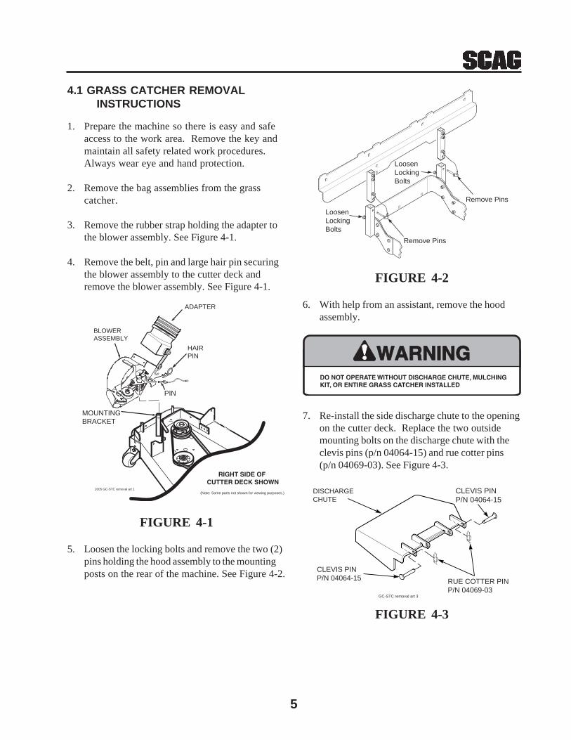
5. Loosen the locking bolts and remove the two (2)pins holding the hood assembly to the mountingposts on the rear of the machine. See Figure 4-2.
4.1 GRASS CATCHER REMOVAL INSTRUCTIONS
FIGURE 4-2
6. With help from an assistant, remove the hoodassembly.
7. Re-install the side discharge chute to the openingon the cutter deck. Replace the two outsidemounting bolts on the discharge chute with theclevis pins (p/n 04064-15) and rue cotter pins(p/n 04069-03). See Figure 4-3.
FIGURE 4-3
CLEVIS PINP/N 04064-15
CLEVIS PINP/N 04064-15
RUE COTTER PINP/N 04069-03
DISCHARGECHUTE
GC-STC removal art 3
WARNINGWARNINGDO NOT OPERATE WITHOUT DISCHARGE CHUTE, MULCHINGKIT, OR ENTIRE GRASS CATCHER INSTALLED
BLOWER ASSEMBLY
MOUNTING BRACKET
PIN
ADAPTER
RIGHT SIDE OF CUTTER DECK SHOWN
(Note: Some parts not shown for viewing purposes.) 2005 GC-STC removal art 1
HAIRPIN
Remove Pins
Remove Pins
LoosenLockingBolts
LoosenLockingBolts

6
GC-STC 48" & 52" BLOWER HOUSING ASSEMBLY
WARNING
INSTALL BELT COVER BEFORE
OPERATING MACHINE
READ OPERATOR'S MANUAL
2005 GC Blower Assembly
12
3
3
45
47
45
4
5
6 7
89
9
10
10
11
11
12
12
13
14
14
14
14
15
1516
17
18
19
20 21
22
23
24
24
26
27
27
27
28
30
3131
32
33
34
35
35
37
38
39
40
41
41
42
43
4410
46
34
29
11
14
17
47
48
49
25
ROTATING BLADES AND BLOWER
DANGERDO NOT OPERATE MOWER
UNLESS GRASS CATCHER OR
DISCHARGE GUARD IS INSTALLED
Stop engine before cleaning or removing
DANGER
DANGERROTATING BLOWER
BLADES
STOP ENGINE BEFORE
ENTERING CHUTE
CONTACT CAN INJURE
50
DANGERDANGER
ROTATING BLOWER
BLADES
STOP ENGINE BEFORE
ENTERING CHUTE
CONTACT CAN INJURE
51

7
GC-STC 48" & 52" BLOWER HOUSING ASSEMBLY
Ref. PartNo. Number Description
27 04019-04 Nut, Serr. Flange 3/8-1628 04001-136 Bolt, Hex Head 3/8-16 x 1-1/2 Gr. 829 481377 Decal, Danger30 461681 Blower Housing Assembly31 04003-12 Bolt, Carr. 5/16-18 x 3/4" Gr. 532 04063-06 Key, 1/4 x 1/4 x 1-1/2"33 451683 Fan Weldment34 483034 Bearing Assembly35 04021-10 Nut, Elastic Stop 5/16-1836 04040-04 Flatwasher, 5/16-.344 x .688 x .06537 421319 Cover, Blower Housing38 48136-02 Clamp, 8-5/8" Max Dia.39 48135-09 Hose, 8.00" Dia. x 53" Long40 482298 Pulley, 4-3/4" O.D. - 1" Bore41 04012-04 Set Screw, 5/16-18 x 3/8"42 451655 Frame, Blower Mount43 481522 Spring, Main Drive44 43212 Spacer45 04019-03 Nut, Serr. Flange 5/16-1846 461723 Adapter w/Strap47 424094 Plate, Blower Catch48 04062-05 Hair Pin Cotter, .243 x 4"49 461680 Blower Housing Assembly, GC-STT50 482080 Decal, Rotating Blower51 481377 Decal, Blower
Ref. PartNo. Number Description
1 04067-07 Pin, Ring 2-1/4" Long2 481547 Lanyard, Deck Height Pin3 04019-02 Nut, Serr. Flange 1/4-204 04001-59 Bolt, Hex Head 1/4-20 x 1-1/4"5 04001-01 Bolt, Hex Head 1/4-20 x 3/4"6 423298 Belt Cover, Rear7 481428 Grip, Blower Lever8 482300 Cap, Square9 04024-02 Nut, Push On 3/8 Thread10 04021-05 Lock Nut, 3/8-1611 04041-07 Flatwasher, 3/8-.391 x .938 x .10512 43277 Spacer13 482299 Pulley, Idler 4" Dia.14 04021-09 Nut, Elastic Stop 3/8-1615 04030-04 Lockwasher, 3/8-1616 423933 Plate, Catch Mounting17 04003-05 Bolt, Carr. 3/8-16 x 1-1/2"18 04001-54 Bolt, Hex Head 3/8-16 x 3" - 52"
04001-46 Bolt, Hex Head 3/8-16 x 2-1/4" - 61"19 04001-81 Bolt, Hex Head 3/8-16 x 3-1/2"20 04001-21 Bolt, Hex Head 3/8-16 x 1-3/4"21 461812 Idler Arm Assembly22 482278 Belt, GC-STC23 482079 Pulley, 3" O.D., GC-STC24 04043-04 Washer, 3/8 Hardened25 43575 Pivot, Idler26 481039 Decal, Belt Cover

8
GC-STC 48" & 52" BLOWER MOUNTING COMPONENTS
1
2
3
4
5
6
6
78
9
10
10
11
1213
14 15
15
16
1718
19
20
390STC203B
21
22
6
RIGHT SIDE OFCUTTER DECK SHOWN
UNDER SIDE OFCUTTER DECK SHOWN
23
24
31
25
2625
26
32
27
27
28
28
29
29
30
FOR MACHINES WITH A SERIALNUMBER BETWEEN7630001 - 8479999
ONLY

9
GC-STC 48" & 52" BLOWER MOUNTING COMPONENTS
Ref. PartNo. Number Description
1 482612 Belt Cover, GC-STC2 04029-04 Wingnut, Plastic 3/8" Small3 482300 Cap, Square Vinyl4 04021-08 Nut, Elastic Stop 1/4-205 461723 Adapter, Blower GC-STC, includes item #76 04040-14 Flatwasher, 1/4-.312 x .750 x .0657 48137-04 Rubber Strap 7-3/4"8 04001-59 Bolt, Hex Head 1/4-20 x 1-1/4"9 481625-01 Knob W/Stud, 3/8-16 x 1-1/4"10 04064-15 Clevis Pin, 5/16 x 1-1/2"11 04069-03 Pin, Rue Cotter 5/16 Dia.12 04067-07 Pin, Ring 1/2 x 2-1/4"13 481547 Lanyard14 482587 Pulley, 4.0" Dia. 1.125 Bore15 04012-04 Setscrew, 5/16-18 x 3/8"16 04021-09 Nut, Elastic Stop 3/8-1617 04030-04 Lockwasher, 3/8"18 04041-07 Flatwasher, 3/8-.391 x .938 x .10519 04003-11 Bolt, Carr. 3/8-16 x 1-1/4" Grade 520 451693 Mounting Post Weldment, Blower21 423708 Belt Cover22 04110-03 U-Nut23 04017-05 Bolt, Hex Head 1/4-20 x 3/4"24 04003-23 Bolt, Carriage 3/8-16 x 1"25 04021-09 Nut, Elastic Stop 3/8-1626 04041-07 Flatwasher, 3/8-.391 x .938 x .10527 04001-09 Bolt, Hex Head 5/16-18 x 1"28 04040-15 Flatwasher, 5/16-.375 x .875 x .08329 04021-10 Nut, Elastic Stop 5/16-1830 04019-02 Nut, Serrated Flange 1/4-2031 423633 Baffle, 48"
423629 Baffle, 52"32 423955 Baffle, Turbo 48" Deck
423956 Baffle, Turbo 52" Deck

10
GC-STC BUCKET SUPPORT COMPONENTS (UPPER)
1
2
34
4
6
8
5
59
9
9
9
5
11
516
16
16
16
16
16
18
18
13
13
19
20
14
2121
22
23
23
24
31
11
5
32
33
33
26
27
28
29
30 32
33637
35
25
31
3538
17
15
934
45
7
12
10
39
40

11
GC-STC BUCKET SUPPORT COMPONENTS (UPPER)
Ref. PartNo. Number Description
1 423302 Screen, Catcher Hood2 04090-02 Pop Rivet, 3/16 x .6523 04041-19 Flatwasher, 3/16-.196 x .469 x .0484 04001-32 Bolt, Hex Head 3/8-16 x 1-1/4"5 04041-01 Flatwasher, 3/8-.391 x .938 x .1056 461408 Hood Assembly, GC-STT (includes items 1, 2 & 3 and items 2 & 15 on page 13)7 04001-117 Bolt, Hex Head 7/16-14 x 1-3/4"8 423258 Hinge, Upper LH9 04021-09 Nut, Elastic Stop 3/8-1610 04040-11 Flatwasher, 7/16-.500 x 1-1/4"11 04001-46 Bolt, Hex Head 3/8-16 x 2-1/4"12 04021-11 Nut, Elastic Stop 7/16-1413 04001-20 Bolt, Hex Head 3/8-16 x 1-1/2"14 04001-135 Bolt, Hex Head 3/8-16 x 1-3/4" Grade 815 451516 Support Weldment, Bag Frame16 04019-04 Nut, Serrated Flange 3/8-1617 04090-03 Rivot, 3/16 x .402 POP18 43546 Bushing, Hopper Pivot19 482304 Spring, Hood Hinge20 423436 Hinge, Lower LH21 43212 Spacer22 04021-05 Locknut, 3/8-1623 43277 Spacer24 423259 Hinge, Upper RH25 423261 Hinge, Lower RH26 48135-13 Hose, 8" Dia. x 56"27 48136-02 Clamp, 8-5/8" Max Dia.28 482422 Tube, Filler29 482421 Elbow30 04001-10 Bolt, Hex Head 5/16-18 x 1-1/4"31 04021-10 Nut, Elastic Stop 5/16-1832 04040-15 Flatwasher, 5/16-.375 x .875 x .08333 04041-11 Flatwasher, 3/8- .406 x 1-1/2" x .17934 04030-04 Lockwasher, 3/8" Spring35 482409 Latch36 04010-25 Screw, #10-32 x 3/4"37 04021-01 Nut, Elastic Stop #10-3238 04001-08 Bolt, Hex Head 5/16-18 x 3/4"39 451517 Support Weldment, Weights40 461097 Weight Assembly

12
GC-STC BUCKET SUPPORT COMPONENTS (LOWER)
STC 2002 BSC
1
2
11
14
1516
17
181920
21
22
23
24
413
5
4
67
8
4
3
8
12
67
4
4
5
FRAME
9
4
5
1010A
"A"
TO "A"
3
6
6
9

13
GC-STC BUCKET SUPPORT COMPONENTS (LOWER)
Ref. PartNo. Number Description
1 04090-02 Pop Rivet, 3/16 x .6522 482321 Seal, Hood3 423262 Tube, Upright4 04041-07 Flatwasher, 3/8-.391 x .938 x .1055 04021-09 Nut, Elastic Stop 3/8-166 04020-04 Nut, 3/8-167 04021-05 Hex Lock Nut, 3/8-168 04067-07 Pin, Ring 1/2 x 2-1/4"9 04001-19 Bolt, Hex Head 3/8-16 x 1"10 451726 Mounting Bracket Weldment RH10A 451725 Mounting Bracket Weldment LH11 04021-02 Lock Nut, 1/4-20 Center12 04001-46 Bolt, Hex Head 3/8-16 x 2-1/4"13 04001-31 Bolt, Hex Head 3/8-16 x 2-1/2"14 482569 Bag Assembly, GC-STT15 423312 Retainer, Seal16 451516 Support, Bag Frame17 04003-02 Bolt, Carr. 1/4-20 x 3/4"18 04001-08 Bolt, Hex Head 5/16-18 x 3/4"19 423198 Mount, Bag Frame Tube20 04003-12 Bolt, Carr. 5/16-18 x 3/4"21 423197 Tube, Bag Support22 04019-03 Nut, Serr. Flange 5/16-1823 04040-15 Flatwasher, 5/16-.375 x .875 x .08324 04021-10 Nut, Elastic Stop 5/16-18

14
GC-STC DECALS
481039
482275
481327
483037
481377
483039

LIMITED WARRANTY- COMMERCIAL ACCESSORY
Any part of the Scag commercial accessory manufactured by Scag and found, in the reasonable judgment of Scag,to be defective in material or workmanship, will be repaired or replaced by an Authorized Scag Service Dealer withoutcharge for parts and labor.
The Scag accessory, including any defective part, must be returned to an Authorized Scag Service Dealer withinthe warranty period. The expense of delivering the accessory to the dealer for warranty work and the expense ofreturning it back to the owner after repair or replacement will be paid for by the owner. Scag’s responsibility in respectto claims is limited to making the required repairs or replacements, and no claim of breach of warranty shall be causefor cancellation or rescission of the contract of sale of any Scag machine. Proof of purchase will be required by thedealer to substantiate any warranty claim. All warranty work must be performed by an Authorized Scag ServiceDealer.
This warranty is limited to 90 days from the date of original retail purchase for any Scag accessory that is used forcommercial purposes, or any other income-producing purpose including rental use.
This warranty does not cover any accessory that has been subject to misuse, neglect, negligence, or accident, orthat has been operated in any way contrary to the operating instructions as specified in the Operator's Manual. Thewarranty does not apply to any damage to the accessory that is the result of improper maintenance, or to anyaccessory or parts that have not been assembled or installed as specified in the Operator's Manual.
The warranty does not cover any accessory that has been altered or modified. In addition, the warranty does notextend to repairs made necessary by normal wear, or by the use of parts or accessories which, in the reasonablejudgment of Scag, are either incompatible with the Scag mower or adversely affect its operation, performance ordurability. This warranty does not cover engines and electric starters, which are warranted separately by theirmanufacturer.
Scag Power Equipment reserves the right to change or improve the design of any accessory without assuming anyobligation to modify any accessory previously manufactured.
All other implied warranties are limited in duration to the 90 day warranty period. Accordingly, any such impliedwarranties including merchantability, fitness for a particular purpose, or otherwise, are disclaimed in their entiretyafter the expiration of the appropriate ninety day warranty period. Scag’s obligation under this warranty is strictlyand exclusively limited to the repair or replacement of defective parts and Scag does not assume or authorize anyoneto assume for them any other obligation. Some states do not allow limitations on how long an implied warranty lasts,so the above limitation may not apply to you.
Scag assumes no responsibility for incidental, consequential or other damages including, but not limited to, expensefor gasoline, oil, expense of delivering the machine to an Authorized Scag Service Dealer and expense of returningit back to the owner, mechanic’s travel time, telephone or telegram charges, rental of a like product during the timewarranty repairs are being performed, travel, loss or damage to personal property, loss of revenue, loss of use ofthe mower, loss of time, or inconvenience. Some states do not allow the exclusion or limitation of incidental orconsequential damages, so the above limitation or exclusion may not apply to you.
This warranty gives you specific legal rights, and you may also have other rights which vary from state to state.

PART NO. 03154PRINTED 8-2004PRINTED IN USA
© 2004SCAG POWER EQUIPMENTDIVISION OF METALCRAFT OF MAYVILLE, INC.WWW.SCAG.COM