2007 perp owners manual supplement en
DESCRIPTION
perp owners manualTRANSCRIPT

1
Please note that the specifications and information in this manual are subject to change for product improvement. For the latest product information, go to http://www.cannondale.com/tech/.
READ THIS MANUAL CAREFULLY!It contains important safety information.
Keep it for future reference.
perp Owner’s Manual Supplement
120027.PDF
CONTENTS
SAFETY INFORMATION ...........................About This Supplement .......................2Safety Messages ....................................2Intended Use ..........................................3
ABOUT FREERIDING & DOWNHILL ....... 4BUILDING UP A FRAMESET ................... 6SELECTING REAR SHOCKS ..................... 6SAG ....................................................... 6CHAIN LENGTH ...................................... 7CHAIN RETENTION DEVICES .................. 7MAXIMUM FORK LENGTH ..................... 8SELECTTING TIRES .................................. 9CABLE ROUTING ...................................10LINE & CABLE FRAME PROTECTION ..... 12HOUSING GUIDES & CABLE STOPS ...... 13BB FD CABLE GUIDE .............................. 13CHAINSTAY PROTECTOR ....................... 13
MAINTENANCE .....................................14About Cleaning .................................... 15Tightening Torques ............................. 15
REAR SHOCK ........................................ 20Changing Travel ................................... 17
SHOCK LINK ..........................................18BUSHING PRESS TOOL ......................... 20SWINGARM PIVOT ............................... 24SELECTING TIRES .................................. 23BRAKE LINK .......................................... 26REAR AXLE/ DROPOUTS ...................... 28
Wheel Truing Tool .............................. 29GEOMETRY ........................................... 30SPECIFICATIONS .................................... 31REPLACEMENT PARTS .......................... 32

2
about this supplement Cannondale Owner’s Manual Supplements provide important model specific safety, maintenance, and technical information. They are not replacements for your Cannondale Bicycle Owner’s Manual.
This supplement may be one of several for your bike. Be sure to obtain and read all of them.
If you need a manual or supplement, or have a question about your bike, please contact your Cannondale Dealer immediately, or call us at one of the telephone numbers listed on the back cover of this manual.
You can download Adobe Acrobat PDF versions of any Cannondale Owner’s Manuals or Supplements from our website: http://www.cannondale.com/bikes/tech.
• This manual is not a comprehensive safety or service manual for your bike.
• This manual does not include assembly instructions for your bike.
• All Cannondale bikes must be completely assembled and inspected for proper operation by a Cannondale Dealer before delivery to the owner.
WARNINGThis document may include procedures beyond the scope of general mechanical aptitude.
Special tools, skills, and knowledge may be required. Improper mechanical work increases the risk of an accident. Any bicycle accident has risk of serious injury, paralysis or death. To minimize risk we strongly recommend that owners always have mechanical work done by an authorized Cannondale retailer.
safety messagesIn this manual, information which affects your safety is emphasized in the following ways:
WARNINGA WARNING indicates a potentially hazardous situation which, if not avoided, can result in serious injury or death.
CAUTIONA CAUTION Indicates a potentially hazardous situation which, if not avoided, can result in serious damage to the product. The matters described under CAUTION may, if not avoided, lead to personal injury, or results depending on the situation and degree of damage. Important matters are described in CAUTION (as well as WARNING), so be sure to observe them.
A NOTE provides helpful information or tips intended to make the information presented clearer.

120027.PDF
3
intended use
Gravity, Freeride, DownhillINTENDED for riding that includes the most difficult terrain that only very skilled riders should attempt.
Gravity, Freeride, and Downhill are terms which describe hardcore mountain, north shore, dirt jumping, slopestyle, hucking etc. This is “extreme” riding and the terms describing it are constantly evolving.
Gravity,Freeride, and Downhill bikes are heavier and have more suspension travel than All-Mountain bikes, allowing them to be ridden in more difficult terrain, over larger obstacles and larger jumps. Gravity,Freeride, and Downhill bikes are bikes are the longest in suspension travel and use components that fit heavy duty intended use. While all that is true, there is no guarantee that some extreme riding will not break a Freeride bike.
The terrain and type of riding that Freeride bikes are designed for is inherently dangerous. Appropriate equipment, such as a Freeride bike, does not change this reality. In this kind of riding, bad judgment, bad luck, or riding beyond your capabilities can easily result in an accident, where you could be seriously injured, paralyzed or killed.
NOT INTENDED to be an excuse to try anything! Read our “Freeride & Downhill” warning on pages 4 and 5.
TRADE OFF Freeride bikes are more rugged than All-Mountain bikes, for riding more difficult terrain. Freeride bikes are heavier and harder to ride uphill than All-Mountain bikes.
WARNINGUSING YOUR BICYCLE IMPROPERLY IS HAZARDOUS.

4
about freeriding & downhill
WARNINGFREERIDING AND OTHER FORMS OF “EXTREME RIDING” ARE EXTREMELY DANGEROUS. YOU CAN BE SEVERELY INJURED OR KILLED IN A SERIOUS ACCIDENT. Freeriding, jumping, hucking, dirt jumping, mountaincross, downhill, slalom, slopestyle, urban or street riding or other evolving forms of extreme or hard core mountain biking are inherently dangerous and can lead to serious accidents. Wear all safety gear and be sure your bike is in excellent condition. Follow all the instructions and warnings below. These steps will reduce, but not eliminate, the inherent risks. Even with state of the art protective safety gear you could be seriously injured, paralyzed or killed. If you do not want to take these risks, do not engage in this type of riding.
Fundamental Risk Freeriding, jumping, hucking, dirt jumping, mountaincross, downhill, slalom, slope-style, urban or street riding. It seems that everywhere you look, from Mountain Dew® commercials to the X-Games® to the Red Bull®Rampage, riders are grabbing big air and sticking sick drops. And it sure looks fun. But what the videos and bike magazines and ads don’t always tell you is that extreme riding takes an amazing amount of skill. Some of the riders you see are well-paid pros who have gradually built up their skills through endless hours of practice, and who have also had their share of stitches, concussions and busted bones (and bikes). Others are daredevils who have chosen to accept or ignore the risks. Would you allow anyone to say that you are so weak in the head, and have such poor judgment that you copy those you see in the media without thought of the serious risks? The stakes are high if you screw up. Realize too late that you aren’t up to the challenge, and you run the risk of major injury or even – say it aloud – death, paralysis. In short, extreme riding carries a high degree of fundamental risk, and you bear the ultimate responsibility for how you ride and what you attempt to pull off. Do you want to avoid these significant risks? Then do not ride this way.
continued on next page . . . . .

120027.PDF
5
Product Limitations Problems of pilot error aside, hard-core riding also beats the heck out of your equip-ment. Although we build and test our bikes to make them tough, there’s no way that we can guarantee they’ll survive your umpteenth six-foot drop. For starters, there is no industry “jumping” standard. The many circumstances of takeoff, landing, speed, rider technique, etc. are unique. The judgment, lack of judgment or insanity of a rider who may ride a Cannondale bicycle cannot be completely predicted, so it’s flat-out impos-sible to predict how anyone’s equipment is going to hold up. Let’s get another thing straight. Buying a Freeride bike does not make you any better. Do not confuse the built-in capabilities of equipment with your own capabilities, which must be learned. Keeping your bike and all its components in good working order is critical, and it’s up to you to maintain and inspect it. Even so, your sweet rig isn’t going to last forever. Nothing does, particularly bikes and parts that are built to minimize weight and then are subjected to abuse. Cannondale frames carry a warranty, but that’s to cover issues with workmanship and/or materials. (See the Cannondale Warranties section of the Owner’s Manual.) The warranty doesn’t mean that they’re going to last forever. They’re not. The warranty certainly doesn’t mean that the bicycle can in any way protect you from injury.
In Conclusion If you’re going hard-core, be smart about it. Always wear a full face helmet, body armor, full-finger gloves and protective clothing. Choose a bike that’s right for you, your riding and terrain, and check it often for signs of fatigue or other trouble. (Your dealer can help you on both fronts.) Read the Mountain Bike Riding section of the Cannondale Bicycle Owner’s Manual. And most importantly, know your limitations. Practice. Stay in control, and carefully, gradually expand your limits – but ride within them.

6
building up a framesetConsult with your Cannondale Dealer and the component manufacturers and frankly discuss your riding style, ability, weight, and interest in and patience for maintenance.
Generally speaking, lighter weight components have shorter lives. In selecting lightweight components you are making a trade-off, favoring the higher performance that comes with less weight over longevity. If you choose more lightweight components you must inspect them more frequently. If you are a heavier rider or have a rough, abusive or “go for it” riding style, buy heavy duty components.
Make sure the components chosen are compatible with your bike and intended for your weight and riding style. Read and follow the component manufacturers warnings and instructions.
selecting rear shocks
WARNINGSELECT ONLY COMPATIBLE SHOCKS AND FORKS FOR YOUR BIKE. DO NOT MODIFY YOUR BIKE IN ANY WAY TO MOUNT ONE. HAVE YOUR SHOCK OR FORK INSTALLED BY A PROFESSIONAL BIKE MECHANIC
• Riding with the wrong rear shock can damage the frame. You could have a serious accident. Make sure the total travel, eye-to-eye length, and stroke length of the rear shock you select meet the specifications listed in this manual.
• When selecting different shocks or forks for your bike, make sure that the shock or fork you select is compatible with your bike’s design and how you will use your bike.
sagSag is the distance the bike suspension compresses with a rider (wearing all appropriate gear) mounted in a normal riding position (seated, hands on handlebar and feet on the pedals) on flat ground.
The recommended sag for your bike is intended to maximize the bike’s suspension travel and it is usually specified as a percentage (%) of the fork or shock’s total travel.
Maintaining the recommended sag in both the front and rear suspension helps assure that the fork and shock operate normally without excessive top-out or bottom-out that can lead to difficult handling or damage.

120027.PDF
7
CAUTIONPlease read the fork and rear shock manufacturer’s owner’s manual and instructions provided before attempting any set-up or adjustment.
Small adjustments to sag are performed by adjusting preload of the shock or fork. This is done by adding or removing spring shims, adjusting the installed length of the spring with a preload adjusting ring, or with air springs, changing air pressure settings.
Larger adjustments to sag may require changing the installed springs in the fork or shock. Changing the spring may be a simple task or very complex depending on the design of the fork or shock. In general: increasing preload decreases sag, decreasing preload increases sag.
Finding a suitable sag setting within the suspension fork or rear shock range is a matter of personal preference taking body weight and how you ride into consideration.
chain lengthWhen building a frameset into a bike, or when you need to replace your chain, there are two methods to determine the correct chain length:
METHOD 1 Position the chain on the largest front chain ring, the largest rear cog, and through the rear derailleur (with the cage at a 45° angle). Measure the chain length required and add two full links more to the length.
METHOD 2 Remove the rear shock to simulate full compression of the suspension. With the chain on the big front chain ring, the big rear cog, and through the rear derailleur (with the cage at a 45° angle), measure the chain length. Use the actual chain length measured.
WARNING Riding with the wrong chain length (one that is too short or too long) may damage the chain, rear derailleur, derailleur hanger, swingarm, and/or other drivetrain components, and may cause a crash, possibly resulting in injury or death. Make sure chain length is correct. Consult with your Cannondale Dealer.
chain retention devicesThe bottom bracket design is compatible with chain retention devices conforming to the International Standard Chain Guide 2005 (ISCG 05).
However, due to variances in design within the ISCG 05 standard and component quality, some “compatible” devices may fit and work better than others. For that reason, we recommend that you run the rear suspension through its complete range of travel when checking the device for interference. As always, its a great idea to consult with your Cannondale Dealer about compatibility before deciding on any component for your bike.

8
maximum fork lengthMaximum Fork Length is an important frame safety testing specification. You must observe the measurement when installing headset parts, headset adapters, installing and adjusting a fork, and replacement forks. The specification is printed on a warning label indicated in the figure below. In this manual, the number is also listed in the specifications section.
MAXIMUMFORKLENGTH
WARNINGMAXIMUM FORK LENGTH
See Owner’s Manual Supplement.
The Maximum Fork Lengthin millimeters will be printedon the label.
HEADTUBE
HEADSETPARTS orADAPTERS
WARNINGDO NOT INSTALL HEADSET PARTS OR FORKS RESULTING IN A MAXIMUM FORK LENGTH LONGER THAN THE SPECIFICATION FOR YOUR FRAME. DO NOT ADJUST A TRIPLE CLAMP FORK SO THAT MAXIMUM FORK LENGTH EXCEEDS THE FRAME LIMIT. Exceeding the MAXIMUM FORK LENGTH limit can overload the frame causing it to fail (break) while riding.
YOU CAN BE SEVERELY INJURED, PARALYZED OR KILLED IN AN ACCIDENT IF YOU IGNORE THIS WARNING.
HOW TO MEASURE:
1. Temporarily install the fork into the headtube with the headset/adapter in use.
2. Fully extend the fork. If the fork is a triple clamp type, extend the legs to maximum designed length.
3. Measure the distance from the bottom of the head tube to the center of the wheel axle.
Do not measure from the bottom of headset bearing cups or head tube adapters. The measurement MUST be taken from the bottom of the head tube!!
610mm

120027.PDF
9
selecting tiresAny properly installed and inflated tire must not contact any part of the swingarm, frame, or fork and throughout full suspension travel.
The U.S. Consumer Product Safety Commission (CPSC) requires at least 1/16” (1.6 mm) tire clearance from any part of the bike. Allowing for lateral rim flex and a wheel or rim that is out-of-true will likely mean choosing a rear tire that provides even more clearance than the CPSC recommends.
Also, your choice of replacement tires should be made only after considering the clearance guidelines contained in suspension product owner’s manual.
If the manufacturer’s manual contains no such guidelines, or if you don’t have a manual, consider that Rock Shox requires at least 1/4” (5 mm) clearance between the tire and the fork crown or bridge when the fork is completely compressed.
Be aware that completely compressing the fork may involve removing the spring stack, letting the air out of the fork, or both.
WARNINGSELECT PROPERLY SIZED/ FITTED TIRES FOR YOUR BIKE.
Mounting the wrong size tires on your bike can increase the chances that you will have an accident where you can be severely injured, paralyzed, or killed. If the tires touch the frame or fork when riding, you can lose control of your bike. If a moving tire is stopped because it touches the frame or fork, you can be thrown off the bike. You can be severely injured or killed.
Do not mount oversized tires, ones that rub or touch the frame, ones that result in too little clearance with the frame, or ones that can touch the frame or fork when the suspension is fully compressed or when riding.
Take care that the tires you select are compatible with your bike’s frame design. Also, be sure to follow the manufacturer’s recommendations of your front fork and rear shocks.
Ask your Cannondale Dealer for the right tires for your bike and its particular components!

10
GROMMETCannondale Kit # KF102/ (10pk) GROMMET
Cannondale Kit # KF102/ (10pk)
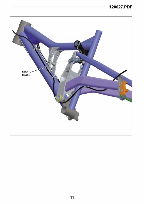
cable routing
REAR BRAKE
REAR DERAILLUER
FRONT DERAILLUER
(full housing)
120027.PDF
11
REAR BRAKE

12
line and cable frame protectionNormal line and cable movement against the frame can wear away painted finishes and decals. Overtime, cable rubbing can wear into the frame itself causing very serious frame damage.
Check over your bike after your first few rides. Apply a clear adhesive guard material in areas where rubbing is found.
When applied correctly, clear guards are good protection for your bike.
Cannondale Kit # KF103/ (8 PK)
To apply the guard material
(included with your bike):
1. Clean the frame with a mild detergent and wipe dry with a clean towel. Do not use solvents or harsh chemicals to clean the frame. OPTIONAL: Trim the adhesive guard material to the shape required.
2. Remove the backing and position the guard under the cable/ line.
3. Rub the guard firmly against the frame with your fingers to fix it in place.
4. Periodically, recheck the guards and other areas of the frame as you continue to ride. Replace the guards if they wear out.
PLEASE NOTE: Damage to your bike caused by cable rubbing is not a condition covered under your warranty. Also, adhesive frame guards are not a fix for incorrectly installed or routed cables or lines. If you find that applied guards are wearing out very quickly, consult with your Cannondale Dealer about the routing on your bike.
PHOTO ABOVE SHOWS A TYPICAL LOCATION FOR THE GUARD. IN THIS CASE, ITS THE AREA IN FRONT OF THE SWINGARM ON THE DOWNTUBE.

120027.PDF
13
housing guides and cable stopsLines and cables on your bike are routed through frame guides using cable stops (1) and /or cable thru guides (2).
Periodically, you should check to make sure the stops and guides are in good condition and seated properly in the frame guides.
For stops, make sure the stop is seated securely in the frame guide and the housing is fixed within the stop.
(a)
1
2
Cannondale Kit # KF014/(2 PK)
Cannondale Kit # KF086/(10 PK)
bottom bracket front derailleur cable guideThis snap in front derailleur cable guide is mounted on the lower bottom bracket shell.
Cannondale Kit # KF085/
chainstay protector An adhesive chainstay protector is located on the underside of the right chainstay. This guard protects the chainstay from damage caused by the chain. Check the condition of the right chainstay protector periodically and replace it when it is worn or missing.
Cannondale Kit # KF078/

14
maintenance & adjustmentThe following table lists only supplemental maintenance items. Please consult your Cannondale Bicycle Owner’s Manual for more information on basic bike maintenance. Consult with your Cannondale Dealer to create a complete maintenance program for your riding style, components, and conditions of use. Follow the maintenance recommendations given by the component manufacturers for the various non-Cannondale parts of your bike.
WHAT TO DO HOW OFTEN
CHECK FOR CABLE RUB, INSTALL PROTECTIVE GUARDS AFTER FIRST RIDE
FRAME INSPECTIONClean and visually inspect entire bike frame/swingarm/linkage assembly for cracks or damage. See “Inspect For Safety” in your Cannondale Bicycle Owner’s Manual.
BEFORE AND AFTER EACH RIDE
CHECK TIGHTENING TORQUESIn addition to other component specific tightening torques for your bike, check items listed in tightening torques in this manual.
BEFORE EVERY RIDE
DISASSEMBLE, CLEAN, INSPECT, RE-GREASE, REPLACE WORN OR DAMAGED PARTS IN THE FOLLOWING ASSEMBLIES:
• (OPTIONAL) BRAKE CARRIER AND LINK ARM• BRAKE LINK ARM. • SHOCK LINK ASSY• SWINGARM PIVOT
IN WET, MUDDY, SANDY CONDITIONS
EVERY 25 HRS.
IN DRY, CONDITIONS EVERY 50 HRS.
WARNINGANY PART OF A POORLY MAINTAINED BIKE CAN BREAK OR MALFUNCTION LEADING TO AN ACCIDENT WHERE YOU CAN BE KILLED, SEVERELY INJURED OR PARALYZED. Please ask your Cannondale Dealer to help you develop a complete maintenance program, a program which includes a list of the parts on your bike for YOU to check regularly. Frequent checks are necessary to identify the problems that can lead to an accident.

120027.PDF
15
about cleaningWhen cleaning your bike:
USE ONLY A MILD SOAP AND WATER SOLUTION. Clean water and a common dish washing liquid will work best.
COVER SENSITIVE AREAS WITH A CLEAN PLASTIC BAG. Secured temporarily with a rubber band or masking tape, a bag can prevent water damage to various bike components (bearings, seals, fork / shock adjustment features).
SPRAY OFF BEFORE WIPING. To preserve the appearance of paint, finish, and decals, use an low pressure water hose to first spray off heavy soils and dirt.
CAUTIONDO NOT power wash or spray water under high pressure to clean. Power washing will force contaminants into parts where they will promote corrosion, immediately damage, or result in accelerated wear.DO NOT use compressed air to dry. DO NOT use abrasive or harsh chemical cleaner/solvents which can damage the finish or attack and destroy both the outside and internal parts. When rinsing, avoid directing the spray directly at shock/fork adjusters or bearings.
tightening torquesITEM Detail N•m In•Lbs Loctite™
FRONT SHOCK MOUNTING BOLT A 5.0 44.0 242 (blue)TOP TUBE PIVOT SCREW B 5.0 44.0 222 (purple)MAIN PIVOT NUT C 12.0 106.0SWINGARM AXLE NUT D 7.0 62.0 242 (blue)SHOCK AXLE NUT E 10.0 89.0 242 (blue)BRAKE LINK ARM MOUNTING BOLTS F 10.0 89.0 242 (blue)REPLACEABLE DROPOUT BOLTS G 10.0 89.0 242 (blue)12MM THRU AXLE BOLT H 12.0 106.0 242 (blue)AXLE CLAMP BOLTS I 10.0 89.0 242 (blue)

16
rear shockchanging travelThe Perp has two travel positions: 180mm and 200mm. Travel is changed by moving the top tube pivot mounting point of the shock link arms and the front shock mount hole position. See next page. There are only two travel positions and you can not use other hole combinations. The reservoir position can be changed by rotating the shock without disconnecting the shock linkage. You will have to remove the top tube pivot and the front shock bolt and lower the swingarm to do it.
TRAVEL (mm) TOP TUBE HOLEFRONT SHOCK
MOUNT
180 Rear Lower See top right.
200 Front Upper See bottom right
WARNINGKEEP YOUR HANDS AND FINGERS OUT OF PINCH POINTS. Your fingers or hands can be pinched or crushed if they are caught between the swingarm, linkage, tire, or frame when the rear shock is released.
CAUTIONTO PREVENT SERIOUS FRAME DAMAGE:
1. Make sure the rear shock is compatible with your frame. Ensure that the shock eyelet-to-eyelet length stroke length match the information in the specifications section of this manual.
2. Make sure the physical shape of the rear shock (including all reservoir and adjustments features) will not cause interference with or contact the frame, frame mounting points, or the swingarm at any point in the full suspension travel. See our website TECH CENTER (http://www.cannondale.com/bikes/tech/) for more on how to mount the OEM shocks for your bike.
3. Do not alter or modify the frame/swingarm in an attempt to mount a rear shock.

120027.PDF
17
200 mm
180 mm
Be sure to align link arms and the top tube frame hole before inserting the pivot by hand.

18
shock link
Gr
23
45
56
23
7
8
1110
910
10
12
1217
17
1717
1616
1313
1513
1315
5mm
7N•m
, 62
In•L
bs
4mm
Loct
ite
222
(pu
rple
)5N
•m, 4
4 In
•Lb
s
5mm
10N
•m, 8
9 In
•Lb
s
6mm
Alle
n K
ey1
5mm
7N•m
62 In
•Lb
sO
nly
gre
ase
item
s 1
and
7D
o n
ot
app
ly g
reas
e to
oth
er p
arts

120027.PDF
19
Cartridge Bearings The sealed cartridge bearings used in the main pivot, top tube pivot and brake carrier assemblies do not require lubrication as part of maintenance. However, you should inspect them regularly and replace them when they are worn out or damaged. To inpect the bearings, remove the pivot or link arm and rotate the inner bearing race with your finger. The bearing should rotate smoothly and quitely. Replace the bearings if the rotation feels rough or gritty. Bearings should be replaced as a new set and not reinstalled if removed. A light film of grease applied to the seal faces of the bearings during reassembly helps to repel damaging moisture.
Sleeve Bushings The sleeve bushings of the swingarm “Y” link and upper link arms will wear out with use, so you should plan to inspect and replace them as needed. The bushings should not be lubricated or greased. Grease will attract grit which when trapped between the parts, act to will wear them away quickly. Replace the bushings as a new set, and be sure to inspect the axles for damage. You can accurately check the bushings for wear using the gauges included in the special tool, Cannondale kit QC746/.
REF QTY DESCRIPTION NOTES1 1 TOP TUBE PIVOT AXLE Clean, Apply a light film of grease.
2 CIRCLIP
3 2 BEARING SKF # 61902-2RS [I.D. 15 x O.D. 28 x W 7mm]
4 1 UPPER LINK ARM, DRIVE SIDE
5 2 BEARING SHIELDThe smooth rounded side (a) face the frame. The flat side
fits against the bearing inner race.
6 1 UPPER LINK ARM, NON-DRIVE SIDE
7 1 TOP TUBE PIVOT CAP Clean, Apply a light film of grease.
8 1 TOP TUBE PIVOT SCREW
9 1 SHOCK AXLE
10 2 SWINGARM “Y” LINK Slight lateral movement is normal.
11 1 SHOCK AXLE NUT
12 1 T-NUT
13 4 TEFLON WASHER
14 2 SWINGARM AXLE NUT
15 2 SWINGARM SLEEVE BUSHING
16 2 LINK ARM SLEEVE BUSHING
17 4 AXLE BUSHING

20
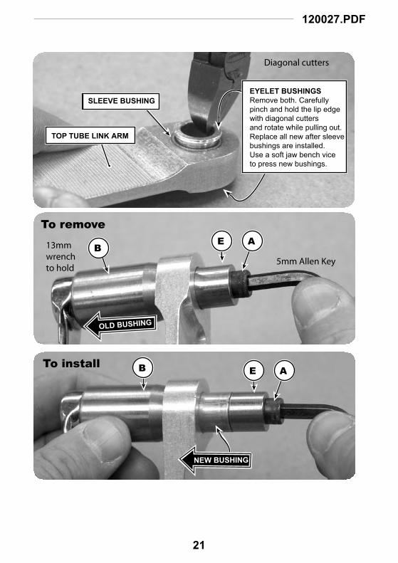
bushing press tool - qc765/The tool kit, includes items A-H shown below. These are necessary to remove the worn sleeve bushings of both the the swingarm and upper link arms and press in new ones. Follow the arrangement of the tool parts on the next two pages to replace bushings. See replacements parts (kits) in this manual.
The tool kit a sizer for the upper link arm bushings (item G) and swingarm bushings (item H). After the bushing are installed, use the tool to draw the sizer through the bushing.
A B
C D E F G H
Cannondale Kit # QC765/
DO NOT USE SIZER H ON BRASS TYPE BUSHINGS
120027.PDF
21
AEB
A
5mm Allen Key
EB
To remove
TOP TUBE LINK ARM
EYELET BUSHINGSRemove both. Carefully pinch and hold the lip edge with diagonal cuttersand rotate while pulling out.Replace all new after sleevebushings are installed.Use a soft jaw bench viceto press new bushings.
SLEEVE BUSHING
Diagonal cutters
OLD BUSHING
NEW BUSHING
To install
13mmwrenchto hold

22
AF
DB
AF
CB
To remove
To install
5mm Allen Key
13mmwrenchto hold
OLD BUSHING
NEW BUSHING

120027.PDF
23
(blank)

24
swingarm pivotThe pivot axle, bearings, and bearing shields are subject to wear depending on use, conditions, and maintenance. Periodic disassembly, cleaning, and regreasing will extend time between necessary renewal.
field check1. Place the bike in a work stand
and remove the rear wheel.
2. Remove the rear shock.
3. Stand behind the bike holding the swingarm by the dropouts.
Lift it up and down. The pivot should move smoothly without sticking allowing the swingarm to fall under its own weight. Be careful, don’t let the swingarm slam against the frame.
Next, still holding the dropouts, try to detect any excessive play side-to-side. Excessive side-to-side play can be caused by a loose pivot nut or damage to the bearings or other pivot parts.
If you find the swingarm movement rough or gritty or detect excessive side-to-side play, the pivot assembly should be inspected. An inspection will require, disassembly, cleaning and parts inspection. Replacement of worn part may be necessary. Have this service performed by your Cannondale dealer.
Pivot Axle & Pivot NutThe pivot must always be installed with the head on the drive side (right) of the frame. The pivot can not be removed without removing the crankset. When the pivot nut is removed the pivot will slide out easily. However, before it is removed the weight of the swingarm should be supported to prevent it dropping suddenly causing injury or damage.
BearingsThe swingarm pivot bearings are a sealed cartridge type and do not require lubrication.
A film of grease applied to the faces of the bearing can be applied to help to repel damaging moisture.
To check the bearings:With the pivot out, rotate the inner bearing race with your finger tip to confirm smooth rotation. Replace bearings if the rotation feels rough or gritty. When necessary, replace bearings as a new set. Drive out the old bearings carefully and install new ones using proper bearing installation tools.
SpacersThe spacers are located between the bearings and frame. The smooth rounded side of the spacer faces the frame while the flatter side of the spacer fits against the bearing.
To check the spacers, remove them and look for any uncharateristic wear, deep grooves, cracks or other damage. Be sure to check the frame bore surfaces as well. A rough surface can accelerate wear. If the spacers are in good shape, clean and regrease them before reinstallation. Make sure they go back in the right way. See the next figure.

120027.PDF
25
PIVOT
BEARING
PIVOT NUT
SPACERS
12 N•m 106 In•LbsLoctite 242 blue
BEARING
The smooth rounded side faces the frame. The other side fits against the bearing inner race.
28mm HEX
10mm HEX
Always clean and apply a lightfilm of grease. Locate pivot headon drive side for chainring clearance.

26
BOLT
BOLT
165mmAXLE
BEARING
SHIELD
SHIELD
SHIELD
SPACER
SPACER
GREASE
U- CUP SEAL
SPERICALBEARING
LINK ARMENDSCIRCLIP
10 N•m 89 In•LbsLoctite 242 blue
10 N•m 89 In•LbsLoctite 242 blue
U- CUP SEAL
BRAKE LINKCARRIER
BRAKE LINKDROPOUT
ARM END PARTS
U-CUP SEAL DETAILS M8X1.25X30 SHCS
M8X1.25X30 SHCS
SKF # 61902-2RS[I.D. 15 x O.D. 28 x W 7mm]
brake carrier & link arm
The brake link assembly shown here is an optional braking system. See REPLACEMENT PARTS (KITS) in this manual for kit ordering information..
Disc brake spacing will change with the installation of the brake link. Select a replacement hub with consideration of wheel dish and spacing.

120027.PDF
27
BOLT
BOLT
165mmAXLE
BEARING
SHIELD
SHIELD
SHIELD
SPACER
SPACER
GREASE
U- CUP SEAL
SPERICALBEARING
LINK ARMENDSCIRCLIP
10 N•m 89 In•LbsLoctite 242 blue
10 N•m 89 In•LbsLoctite 242 blue
U- CUP SEAL
BRAKE LINKCARRIER
BRAKE LINKDROPOUT
ARM END PARTS
U-CUP SEAL DETAILS M8X1.25X30 SHCS
M8X1.25X30 SHCS
SKF # 61902-2RS[I.D. 15 x O.D. 28 x W 7mm]

28
rear axle & dropouts assemblies
NO GAP
NO GAP
150mmAXLE
CR BOLT
CR NUT
CLAMP
BRAKEDROPOUT
DER HGR
BOLTS
AXLE BOLT
BRAKE LINK DROPOUT
A
B
C
D
A
10 N•m 89 In•LbsLoctite 242 blue
10 N•m 89 In•LbsLoctite 242 blue
12 N•m 106 In•LbsLoctite 242 blue
BRAKE LINKCARRIER
Tightening Order = A,B,C,D, E

120027.PDF
29
wheel trueing toolThis special tool is needed to mount the 12 mm Thru axle wheels in trueing stands. Using it ensures proper wheel dish,
Order Cannondale Kit KF079/
NON-DRIVE DRIVE
O-RINGCAP SHAFT
rear wheel removal and installationHere are some things you must remember when removing and reinstalling the rear wheel:
1. Keep your hands and fingers from between the wheel and the swingarm, and out of the shock linkage.
2. Always clean the axle and dropout clamps surfaces before reinstallation.
3. Make sure that the dropout clamps are attached to the swingarm correctly. Follow tightening order.
4. Use an accurately calibrated torque wrench and follow the tightening order shown. Pay attention to GAP and NO GAP. See previous page.

30
geometry
D
K
H
L
B
A
E
G
F
J
I
C
203.2183.2
TRAVEL
▲●
●▲
● ▲
PERPETRATORPerp 1, Perp 2
SIZE SMALL MEDIUM LARGE X-LARGE
Seat Tube Overall (cm/in) STL 15.9/40.5 16.7/42.5 17.3/44 17.3/44
Seat Tube Angle (degree) A 71.0 70 70 70
Head Tube Angle (degree) B 23.2/59 ★ ★ ★
Top Tube Horizontal (cm/in) C 22.6/57.5 23.4/59.5 24.2/61.5 25/63.5
Chainstay Length (cm/in) E 18/45.7 ★ ★ ★
Fork Rake (cm/in) F 1.8/4.5 ★ ★ ★
Bottom Bracket Height (cm/in) G 14.7/37.4 ★ ★ ★
Wheel Base (cm/in) H 44.8/113.8 45.3/115.1 46.2/117.3 46.9/119.3
Fork Trail (cm/in) I 3.8/9.8 ★ ★ ★
Standover TT Midpoint (in/cm) J 30.9/78.5 30.9/78.6 31/78.8 31.1/79
Bottom Bracket Drop (cm/in) K 1.7/4.4 ★ ★ ★
Front Center Distance (cm/in) L 26.9/68.4 27.5/69.8 28.3/71.9 29.1/73.9
Rear Travel 200mm position (in/cm) 8/20.3 ★ ★ ★
Rear Travel 180mm position (in/cm) 7.2/18.3 ★ ★ ★
Shock Eye-to-Eye (in/cm) 7.2/18.3 ★ ★ ★
Shock Stroke (in/cm) 2.75/6.99 ★ ★ ★
Recommended Sag 30% ★ ★ ★
All dimensions are given with suspension fully extended. ★= same spec

120027.PDF
31
specificationsITEM SPECIFICATIONMODEL PERP
FRAME MATERIAL 6061 T6, TIG Welded Aluminum Alloy
SIZES S, M, L
RECOMMENDED SAG 30%
MAXIMUM TIRE WIDTH 76.2mm, 3.0 in
HEADTUBE HEADSHOK, OnePointFive
HEADTUBE HEIGHT 114 mm, 4.5 in
MAXIMUM FORK LENGTH 610mm
SEATPOST DIAMETER 27.2mm
REAR SHOCK MOUNTING BOLT HOLE DIAMETER
FRONT 8.1 ± 0.05mm
REAR 10.0 ± 0.05mm
REAR SHOCK FRONT BUSHING WIDTH 32.4 ± 0.1mm
REAR SHOCK REAR BUSHING WIDTH 17.4 ± 0.1mm
REAR SHOCK EYE-TO-EYE LENGTH 222mm, 8.75in
REAR WHEEL TRAVEL180mm
200mm
REAR SHOCK STROKE LENGTH 70mm, 2.75 in
REAR SHOCK LEVERAGE RATIO@ 200mm 3.75 to 2.38:1 Progressive, 2.9:1 Average
@ 180mm 3.0 to 2.2:1 Progressive, 2.65:1 Average
FRONT DERAILLEUR 31.8 Bottom Pull Top Swing
BOTTOM BRACKET SHELL WIDTH 83mm
BOTTOM BRACKET SHELL THREAD TYPE English
CHAIN LINE 56mm
REAR HUB SPACING 150mm
REAR HUB AXLE Thru12 150mm Thru 12 165mm
REAR BRAKE MOUNT International Standard 6” or 8” rotor compatible
CHAIN RETENTION SYSTEM** International Standard Chain Guide 2005 (ISCG05)
** The bottom bracket design is compatible with chain retention devices conforming to the International Standard Chain Guide 05 (ISCG 05). However, due to variances in design within the ISCG 05 standard and component quality, some “compatible” devices may fit and work better than others. For that reason, we recommend that you run the rear suspension through its complete range of travel when checking the device for interference. As always, its a great idea to consult with your Cannondale Dealer about compatibility before deciding on any component for your bike.

32
replacement parts (kits)ORDER KIT DESCRIPTION
QC748/ KIT,PIVOT MAIN,JUDGE/PERP: MAINPIVOT-AXLE,NUT,2 SPACERS
QC749/ KIT,BEARINGS,MAIN,JUDGE/PERP: 2-BEARINGS
QC750/ KIT,DER.HANGER,JUDGE/PERP: DRIVE AND NON-DRIVE HANGER W/4 BOLTS
QC752/ KIT,DROPOUT,REPL.BRAKE: NON-DRIVE DROPOUT AND HANGER W/ C-RING BOLTS
QC754/ KIT,AXLE,THRU 12X150MM VCG,VNG: AXLE AND END BOLT
QC759/ KIT,SHOCK MOUNT HWARE,VCG/VNG: FRONT AND REAR SHOCK MOUNT HWARE 2 MALE, 2 FEMALE
QC895/ KIT,UPPER LINK ASSY,PERP: COMPLETE SCISSOR LINK ASS’Y
QC896/ KIT,UPPER LINK HWARE,PERP: ALL HWARE FOR SCISSOR LINK. EVERYTHING BUT THE L-R UPPER LINK ARMS AND THE 2 SWINGARM LINKS
QC897/ KIT,SHOCK,FOX VAN R,PERP
QC766/ KIT,HWARE,HIGH WEAR,VCG/VNG
QC898/ KIT,SWINGARM Y-LINKS,PERP
QC765/ KIT,TOOL,BUSHING,VCG/VNG
QC746/ KIT,CUP,HSET,20 OFFSET,SI
KF014/ Kit,Cablestop, Inserts - 2
KF086/ Kit,Hydraul. Brk Guides,10 pcs
KF085/ Kit,BB CABLEGUIDE, SINGLE
KF103/ KIT,GUARD,SCUFFGUARD-8PK
KF078/ Kit,Gemini chnsty undersid pro
QC747/ KIT,UPGRADE,BRAKE LINK,JUDGE :EVERYTHING TO UPGRADE TO THE BRAKE LINK EXCEPT HUB.
For an up to date list of kits available for your bike, please visit our Tech Center at : http://www.cannondale.com/tech/