2008 table of contents - indiana · structural foundations relative to spread footings, driven...
TRANSCRIPT
TABLE OF CONTENTS
Table of Contents...............................................................................................................................1
List of Figures ....................................................................................................................................2 66-1A Editable Foundation Review form...................................................................................2 66-2A Soil Pressure Formulas ....................................................................................................2 66-2B Bar Development Length.................................................................................................2 66-3A Bearing Capacity vs. Shell Wall Thickness (14-in. dia. Steel-Encased Concrete Piles).2 66-3A(1) Minimum Pile Length .................................................................................................2 66-3B Pile Tip Elevation Guidelines (For Body of Water) ........................................................2 66-3C Sample Pile Load Table ...................................................................................................2 66-3D Specification of Level of Pile Testing .............................................................................2 66-4A Drilled Shafts ...................................................................................................................2
Chapter Sixty-six ...............................................................................................................................2
66-1.0 GENERAL..............................................................................................................................2 66-1.01 Introduction ....................................................................................................................2 66-1.02 Required Information .....................................................................................................3 66-1.03 Selection of Foundation Type.........................................................................................3 66-1.04 Factors of Safety.............................................................................................................3 66-1.05 Foundation Approval......................................................................................................4
66-1.05(01) Guidelines for Foundation Review ....................................................................5 66-1.05(02) Foundation Review Procedure...........................................................................6
66-2.0 SPREAD FOOTING ..............................................................................................................7 66-2.01 Minimum Dimensions and Materials .............................................................................7 66-2.02 Footing Thickness and Shear Design .............................................................................8 66-2.03 Depth and Cover.............................................................................................................8
66-2.03(01) Bottom of Footing..............................................................................................8 66-2.03(02) Top of Footing ...................................................................................................8
66-2.04 Soil Pressure ...................................................................................................................9 66-2.05 Settlement .......................................................................................................................9 66-2.06 Reinforcement ................................................................................................................9 66-2.07 Joints...............................................................................................................................10 66-2.08 Stepped Footing..............................................................................................................10 66-2.09 Additions to Existing Footing.........................................................................................11 66-2.10 Cofferdam.......................................................................................................................11 66-2.11 Concrete Foundation (Tremie) Seal ...............................................................................11 66-2.12 Proof Testing of Rock.....................................................................................................12
66-3.0 PILES......................................................................................................................................12 66-3.01 General............................................................................................................................12 66-3.02 Types ..............................................................................................................................13
66-3.02(01) Steel-Encased Concrete Piles.............................................................................13 66-3.02(02) Steel H-Piles.......................................................................................................14
66-3.03 Pile Length [Rev. July 2008]..........................................................................................14 66-3.04 Design Requirements......................................................................................................15
2008

66-3.05 Pile Design for End Bent ................................................................................................17
66-4.0 DRILLED SHAFTS ...............................................................................................................18
66-5.0 SCOUR AND FOUNDATION CONSIDERATIONS ..........................................................19 66-5.01 Hydraulic Considerations ...............................................................................................19 66-5.02 Structural Considerations ...............................................................................................19
LIST OF FIGURES Figure Title 66-1A Editable Foundation Review form 66-2A Soil Pressure Formulas 66-2B Bar Development Length 66-3A Bearing Capacity vs. Shell Wall Thickness (14-in. dia. Steel-Encased Concrete Piles) 66-3A(1) Minimum Pile Length 66-3B Pile Tip Elevation Guidelines (For Body of Water) 66-3C Sample Pile Load Table 66-3D Specification of Level of Pile Testing 66-4A Drilled Shafts
2008
CHAPTER SIXTY-SIX
FOUNDATIONS
A critical consideration for the satisfactory performance of a structure is the proper selection and design of foundations that will provide adequate bearing resistance, tolerable lateral and vertical movements, and aesthetic compatibility. This Chapter discusses criteria for the design of structural foundations relative to spread footings, driven piles, and drilled shafts. 66-1.0 GENERAL This Chapter is largely based upon a traditional design approach, which is based on the service-load design concept. It is acceptable to use load factor design to design a foundation, including piles. However, the following summarizes the concepts in the LRFD Specifications. References shown following section titles are to the AASHTO LRFD Bridge Design Specifications. 66-1.01 Introduction Considering basic design principles for foundations, the LRFD Bridge Design Specifications has implemented a change compared to those principles in the AASHTO Standard Specifications for Highway Bridges. The LRFD Specifications makes a clear distinction between the strength of the native materials (soils and rocks) supporting a bridge and the strength of the structural components transmitting force effects to these materials. The distinction is emphasized by treating the former in Section 10 and the latter in Section 11. The LRFD Specifications is essentially a strength design document with a primary objective to ensure equal, or close to equal, safety levels in all components against structural failure. The distinction is necessitated by the substantial difference in the reliability of native materials and man-made structures. Historically, the primary cause of bridge failure has been the washout of native materials. Substructure failures, other than those precipitated by vessel or vehicular collision, are virtually non-existent. Accordingly, the LRFD Specifications introduced a variety of strict provisions in scour protection, which normally result in deeper substructures.
2008
To ensure maximum economy, the LRFD Specifications requires that components of the substructure be analyzed and proportioned no differently from those of the superstructure. In practical terms, this means that force effects in the substructure and between the substructure and foundation are determined by analysis, as appropriate, and factored according to LRFD Specifications Section 3. Loads generated as a result of earth pressures can be determined with assistance from Section 11. Then the nominal and factored resistance of the substructure is computed according to Section 10. The geotechnical resistance factors provided in the LRFD Specifications are approximately 50% of those provided for structural components. This is the justification for this design philosophy, which permits the designer to tailor the level of design sophistication to the size, importance, and appearance of a bridge. As geotechnical engineers become more familiar with the new LRFD procedures for bridge-substructure foundations, specific values of geotechnical resistance factors for different types of foundation systems at the strength limit state can be developed. 66-1.02 Required Information Prior to the design of the foundation, the designer must have knowledge of the environmental, climatic, and loading conditions expected during the life of the proposed unit. The primary function of the foundation is either to spread concentrated loads over a sufficient area to provide adequate bearing capacity and limitation of movement, or to transfer loads from unsuitable foundation strata to suitable strata. Therefore, knowledge of the subsurface soil conditions, location, and quality of rock, ground water conditions, and scour and frost effects is necessary. 66-1.03 Selection of Foundation Type Section 59-2.0 discusses those types of foundations and the criteria which influence the selection of a foundation type. Other factors to be evaluated when choosing the type of foundation are discussed in Section 59-4.0. 66-1.04 Factors of Safety The following shall be guidelines for minimum factors of safety (FS) for foundation elements. The factor of safety may vary and is dependent upon the structural load, foundation geometry, and soil or rock types. 1. Sliding Movement.
2008
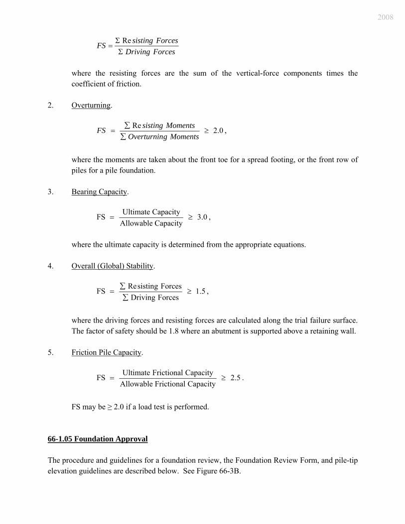
ForcesDrivingForcessistingFS
ΣΣ
=Re
where the resisting forces are the sum of the vertical-force components times the coefficient of friction.
2. Overturning.
0.2Re≥
∑∑
=MomentsgOverturnin
MomentssistingFS ,
where the moments are taken about the front toe for a spread footing, or the front row of piles for a pile foundation.
3. Bearing Capacity.
0.3CapacityAllowable
CapacityUltimateFS ≥= ,
where the ultimate capacity is determined from the appropriate equations. 4. Overall (Global) Stability.
5.1ForcesDrivingForcessistingReFS ≥
∑∑
= ,
where the driving forces and resisting forces are calculated along the trial failure surface. The factor of safety should be 1.8 where an abutment is supported above a retaining wall.
5. Friction Pile Capacity.
5.2CapacityFrictionalAllowable
CapacityFrictionalUltimateFS ≥= .
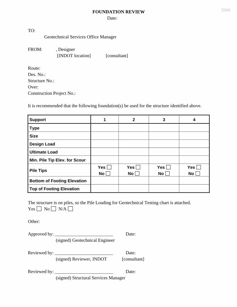
FS may be ≥ 2.0 if a load test is performed. 66-1.05 Foundation Approval The procedure and guidelines for a foundation review, the Foundation Review Form, and pile-tip elevation guidelines are described below. See Figure 66-3B.
2008

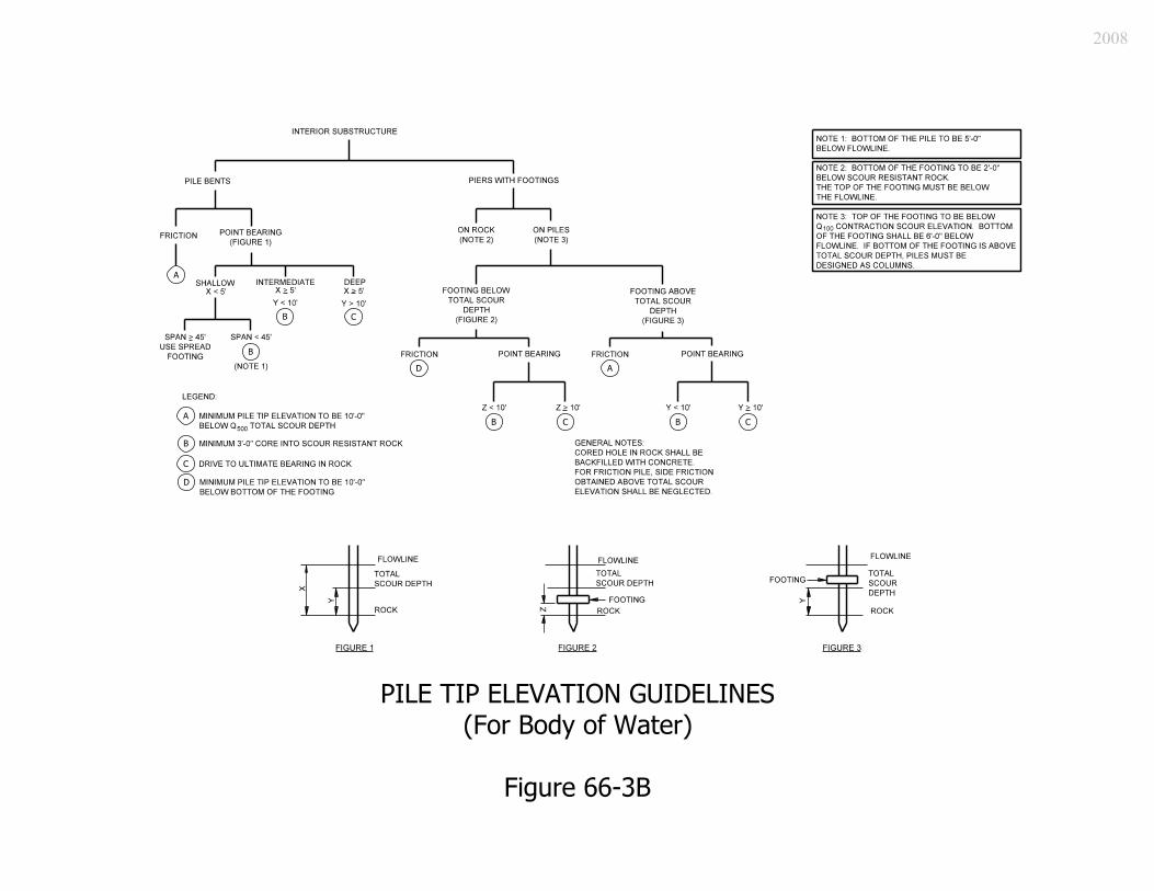
66-1.05(01) Guidelines for Foundation Review A foundation review is to be conducted by the designer for each bridge replacement, bridge construction, box structure that can be classified as a bridge, or three-sided structure including that which cannot be classified as a bridge. It should be conducted at the Preliminary Plans for Final Approval (PPFA) stage. However, it is feasible, but not desirable, to obtain Design Approval without the foundation review. The guidelines for conducting a foundation review are as follows. 1. Minimum pile-tip elevations for scour for the interior substructure should be determined
in accordance with the method outlined in Figure 66-3B, the Pile Tip Elevation Guidelines flowchart.
2. The minimum pile-tip elevation for a pile footing shall be determined using the Q500
scour elevation. 3. Where the bottom of a pile footing is located above the Q100 scour elevation, the piling
should be designed for additional lateral restraint-and-column action for the unsupported pile length above the Q100 scour elevation. A factor of safety of 2.0 should be used. The piling should also be checked for the same criteria using the Q500 scour elevation and a factor of safety of 1.0.
4. The minimum pile-tip elevation for scour should not be confused with the estimated pile-
tip elevation theoretically required to obtain the required bearing. The estimated pile-tip elevation is found in the Geotechnical Report. The lower of these two pile-tip elevations should be used for determining the pay quantity.
5. Proposed top and bottom elevations of footing should be determined in accordance with
the procedure described in Figure 66-3B. 6. The mudsill of approximately 12-in. thickness for a wall pier that has a single row of
piles can be considered as an open pile bent with a very deep cap. Hence, the mudsill need not be placed below the scour elevation.
7. A pier in a floodplain should be designed as a river pier. Its foundation should be located
at the appropriate depth if there is a likelihood that the stream channel will shift during the life of the structure, or that channel cutoffs are likely to occur. For a structure or portion thereof that qualifies as an overflow structure, contact the Production Management Division’s Hydraulics Team.
2008
8. Engineering judgment should always be used in conjunction with Figure 66-3A when recommending pile-tip and footing elevations.
66-1.05(02) Foundation Review Procedure 1. The designer receives the Geotechnical Report. 2. At the PPFA stage, the designer proposes the foundation using Figure 66-1A, the
Foundation Review form. An editable version of this form may also be found on the Department’s website at www.in.gov/dot/div/contracts/design/dmforms/. The information to be provided is as follows.
a. Spread footing. (1) Type: Spread Footing on Rock, or Spread Footing on Soil
(2) Size: N/A (3) Design load: maximum allowable bearing pressure should be shown (4) Ultimate load: N/A (5) Minimum pile tip elevation: N/A (6) Use pile tips: N/A
b. Footing supported on piles or pile bent.
(1) Type: H piles, or Steel Pile Shells (2) In the Other portion, downdrag, if applicable, should be discussed. Other
unique information should be provided. (3) The Pile Loading for Geotechnical Testing chart should be attached.
3. The designer should then transmit the form to the geotechnical engineer who developed
the Geotechnical Report. 4. If the geotechnical engineer approves, he or she signs, dates, and returns the form to the
designer. If the geotechnical engineer disagrees with the recommendations, the marked-up form is returned to the designer for resubmission.
5. Once the geotechnical engineer approves the form, the designer transmits a request for a
foundation review, with the PPFA submittal, which includes the following: a. Geotechnical Report’s summary of bridge-related items; b. General Plan and Layout sheets; c. Foundation Review form; and
2008
d. Scour Review memorandum. 6. The project reviewer reviews the Foundation Review form and signs and dates it once he
or she concurs. 7. The project reviewer submits the form to the appropriate Office of Structural Services
Bridge Engineering Team leader, who transmits it to the Office manager. If the Office manager concurs with the recommendations, he or she signs and dates the form.
8. The Bridge Engineering Team leader transmits the completed Foundation Review form
to the project manager. The Office of Geotechnical Services should receive a copy of the approved Foundation Review form.
66-2.0 SPREAD FOOTING Reference: Articles 5.8, 5.13, 10.6 A spread footing is normally a thick concrete slab whose geometry is determined by structural requirements and the characteristics of supporting components, such as soil, rock, piles, or shafts. Its primary role is to distribute loads transmitted thereto by a pier, bent, abutment or retaining wall. A spread footing is used to transmit loads to suitable soil strata or rock at relatively shallow depths. 66-2.01 Minimum Dimensions and Materials The following criteria will apply. 1. Spread Footing. The minimum thickness is 1.5 ft. 2. Pile Footing. The minimum thickness under a pier, frame bent, abutment, or retaining
wall is 2.5 ft. 3. Class of Concrete. The concrete should be Class B. 4. Concrete Strength. The specified 28-day compressive strength, f’c, is 3000 psi. 5. Reinforcing Steel. The specified minimum yield strength, fy, is 60 ksi.
2008
66-2.02 Footing Thickness and Shear Design The footing thickness may be governed by the development length of the footing dowels (footing to wall or column) or by concrete shear requirements. Shear reinforcement should be avoided. If concrete shear governs the thickness, it is usually more economical to use a thicker footing unreinforced for shear instead of a thinner footing with shear reinforcement. The footing thickness should be increased in 2-in. increments. Requirements for determining the shear resistance are provided in LRFD Specifications Articles 5.8.3 and 5.13.3.6. 66-2.03 Depth and Cover The vertical footing location should satisfy the following criteria. 66-2.03(01) Bottom of Footing The bottom of a footing on soil shall be set below the deepest frost level which is approximately 4 ft. Where a footing is founded on rock, the bottom of the footing shall be embedded a minimum of 2 ft below the top of the rock. However, if the rock surface slopes more than 1 ft, the minimum embedment should be 1 ft at the low end and 2 ft at the high end of the footing. For a grade-separation structure, lesser minimum embedments may be used if recommended in the Geotechnical Report. 66-2.03(02) Top of Footing The top of the footing should have a minimum of 1 ft permanent earth cover. Where the footing is founded in a rock streambed, the top of the footing should not protrude above the top of the rock. At a stream crossing where stream-bed materials are susceptible to scour, the top of a pile footing should be set below what is defined by the LRFD Specifications as contraction scour. The top of the footing should be set sufficiently low to avoid conflicts with the pavement section, including subbase or underdrains.
2008
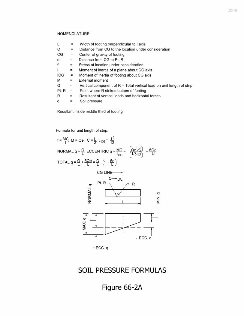
66-2.04 Soil Pressure The resultant of triangularly vertical pressures between the footing and the foundation should be within the middle one-third of a footing on either soil or rock. The soil pressures for such distributions may be calculated according to the formulas provided in Figure 66-2A. The soil pressure formulas shown in Figure 66-2A can be used for a footing loaded eccentrically about one axis (e.g., retaining wall or wingwalls). AASHTO Standard Specifications for Highway Bridges Article 4.4 provides additional information on the treatment of a footing loaded eccentrically. The maximum allowable (service load) soil-bearing pressure should be shown on the General Plan sheet. 66-2.05 Settlement Due to the methods used to determine allowable foundation loads, differential settlement will not need to be investigated. If varying conditions exist, settlement will be addressed in the Geotechnical Report and the following effects should be considered. 1. Structural. The differential settlement of the substructure causes the development of
force effects in a continuous superstructure. These force effects are directly proportional to structural depth and inversely proportional to span length, indicating a preference for a shallow, large-span structure. They are normally smaller than expected and tend to be reduced in the inelastic phase. Nevertheless, they are considered in the design, especially those negative movements which may either cause or enlarge existing cracking in the concrete deck slab.
2. Joint Movements. A change in bridge geometry, especially for a deep superstructure, due
to settlement causes movement in deck joints which should be considered in their detailing.
3. Profile Distortion. Excessive differential settlement may cause a distortion of the
roadway profile that may be undesirable for a vehicle traveling at high speed. 4. Appearance. Viewing excessive settlement may create a feeling of decay, neglect, or
lack of safety. 66-2.06 Reinforcement
2008
Unless other design considerations govern, the reinforcement should be as follows. 1. Longitudinal Steel. Longitudinal distribution bars should be placed in the secondary
direction on top of the primary transverse steel. The diameter of longitudinal distribution bars should be considered a function of the diameter of the transverse steel bars as follows:
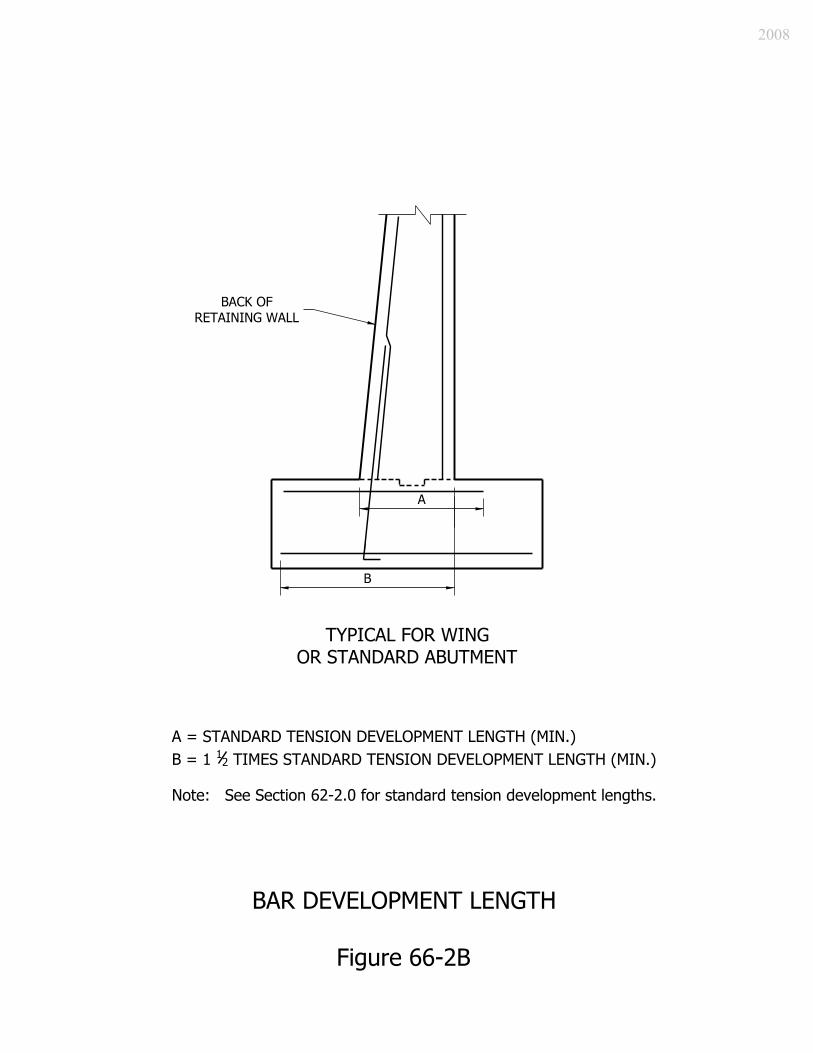
Transverse Steel Longitudinal Steel #4, #5, #6 #4 #7 #5 #8 or larger #6 2. Bar-Embedment Configuration. Bar embedment lengths should be as shown in Figure
66-2B. In a spread footing, hooks may be omitted on transverse footing bars unless development calculations dictate otherwise.
Vertical steel extending out of the footing should be extended down to the bottom footing steel and should be hooked on the bottom end regardless of the footing thickness.
3. Spacing. The spacing should not exceed 1 ft in either direction. 4. Other Reinforcement Considerations. LRFD Specifications Article 5.13.3 specifically
addresses concrete footings. For items not included therein, the other relevant provisions of Section 5 should govern. For a narrow footing, to which the load is transmitted by a wall or a wall-like pier, the critical moment section should be taken at the face of the wall or pier stem and the critical shear section a distance d (effective depth of the footing) from the face of the wall or pier stem where the load introduces compression in the top of the footing section. For other situations, either Article 5.13.3 should be followed, or a two-dimensional analysis may be used for greater economy of the footing. The designer should also check crack control in accordance with LRFD Article 5.7.3.4. The crack control parameter, Z, should be 100 kip/in.
66-2.07 Joints A footing should not require expansion joints. Footing construction joints should be offset 2 ft from expansion joints or construction joints in a wall, and should be constructed with 3-in. depth keyways placed in the joint. 66-2.08 Stepped Footing
2008
The difference in elevation of adjacent stepped footings should not be less than 0.5 ft. The lower footing should extend 2 ft under the adjacent higher footing, or an approved anchorage system may be used. 66-2.09 Additions to Existing Footing At the interface between an existing footing and a new one, existing concrete should be removed as needed to provide adequate development length for lap splicing of existing reinforcement, or an approved anchorage system may be used. A 3-in. keyway should be excavated into the existing concrete, unless the dowel bars are sufficient to resist the vertical shear. Where the substructure of an existing structure is extended, the old footing with respect to the new footing should be shown on the New Footing Details sheet. 66-2.10 Cofferdam The purpose of a cofferdam is to provide a protected area within which an abutment or a pier can be built. A cofferdam is a structure consisting of steel or wooden sheeting driven into the ground and below the bottom of the footing elevation and braced to resist pressure. It should be practically watertight and be capable of being dewatered. The sheeting used will be wood or steel depending upon the depth and the pressure encountered. For more information, see the INDOT Standard Specifications. A cofferdam is designed and detailed by the contractor. A pay item for cofferdam need not be included in the Schedule of Pay Items. The costs associated with a cofferdam are included in the excavation costs if the contractor decides to use that method of abutment or pier installation. See the INDOT Standard Specifications for excavation pay limits. 66-2.11 Concrete Foundation (Tremie) Seal A bridge with foundations located in water requires sheet pile cofferdams to provide dry conditions for construction of the pier foundations. Under certain conditions, such as loose granular soil, the cofferdam cannot be pumped dry due to high-infiltration flows through the bottom of the excavation. A foundation seal must therefore be placed inside the cofferdam and below the proposed bottom of footing to reduce or eliminate the water infiltration. At the preliminary field check, the designer should check with the district construction representative and the geotechnical engineer to determine if a foundation seal should be
2008
investigated for the foundation in question. The geotechnical engineer should determine the need for a seal and include the recommendation in the Geotechnical Report. Because the unreinforced seal slab is primarily to provide dry working conditions, its design is based upon the uplift force due to the amount of water displaced by the cofferdam. If a seal is specified as part of the design, the assumed water surface elevation during foundation construction should be shown on the plans. This elevation is assumed to be approximately 2 ft above the normal water surface elevation. The seal thickness should be determined so that the weight of the concrete in the seal plus friction (bond) on the steel foundation piling is equal to 100% of the weight of the water displaced. The minimum thickness of the seal slab should be 2 ft. The assumed weight of the concrete should be 140 lb/ft3. The resistance force due to friction on the pile should be equal to FbDp, if D < d, or Fbdp, if D ≥ d,where Fb is the allowable bond (friction) stress, d is the H-pile section depth or the shell pile diameter, p is the perimeter, and D is the depth of the seal slab. The allowable service load bond stress between the steel H-pile or shell pile and the seal concrete should be taken as 36 psi. Tension in the concrete seal due to bending moments induced by the force of the water pressing upward on the bottom of the slab minus the weight of the seal concrete should be checked. The piles should be treated as the points of support for the slab. The concrete slab should be treated as an unreinforced concrete beam. The maximum service load tension in the seal concrete should be 25% of 7.5( )cf ′ 1/2.
66-2.12 Proof Testing of Rock All excavations for a spread footing on rock should be proof tested to check the integrity of the rock. See the INDOT Standard Specifications for the proof testing procedure. 66-3.0 PILES Reference: Articles 5.13, 6.9, 6.12, 10.7 66-3.01 General If underlying soils cannot provide adequate bearing capacity, scour resistance, or tolerable settlements, piles may be used to transfer loads to deeper suitable strata through friction or end bearing. The selected type of pile is determined by the required bearing capacity, length, soil
2008
conditions, and economic considerations. Steel-encased concrete piles and steel H-piles are most commonly used. Other pile types, such as auger cast piles or timber, may be considered. 66-3.02 Types 66-3.02(01) Steel-Encased Concrete Piles LRFD Specifications Article 5.13.4.5, and portions of Article 5.13.4.6 for seismic zones, provide specific requirements for steel-encased concrete piles. Additional relevant information may be found in Articles 6.9.5 and 6.12.2.3. The following will apply to steel-encased concrete piles. 1. Usage. These are best suited as friction piles. Depending on the subsurface conditions,
the geotechnical engineer may anticipate that these piles will achieve their capacity through a combination of skin-friction and end-bearing.
2. Diameter. Steel-encased concrete piles will normally be 14 in. in diameter. 3. Class of Concrete. Pile shells should be filled with class A concrete. 4. Material Strength. The specified 28-day compressive strength of concrete, , is 3500
psi. Pile shells should have a minimum yield strength of 35 ksi for Grade 2, or 45 ksi for Grade 3.
cf ′
5. Bearing Capacity and Wall Thickness. The Production Management Division’s Office of
Geotechnical Services will routinely investigate bearing capacities of 80 kip, 110 kip, 140 kip for steel-encased concrete piles. The designer is expected to perform a preliminary feasibility analysis where a bearing capacity higher than 140 kip are desired, and to notify the Office of Geotechnical Services of the desired bearing capacity prior to the beginning of the soils investigation, which is usually at the preliminary field check stage. This should also be documented in the field check minutes. Figure 66-3A provides suggested bearing values for a range of available steel shell wall thicknesses.
The designer should use a single steel shell wall thickness where the piling for the different substructure elements is in different bearing-capacity ranges. Wall thicknesses other than those shown in Figure 66-3A are subject to limited availability and should not be used without justification and assurance of availability.
6. Protection for Exposed Piles. Only fusion-bonded (powdered epoxy resin) epoxy coating
should be used. The epoxy coating should be extended to 2 ft below the flow-line elevation. The epoxy coating is vulnerable to handling and driving. Because of the
2008
vulnerability of the epoxy coating near the flowline, reinforcing steel is included in the top part of the pile. See the INDOT Standard Drawings.
7. Construction. The designer should consider the driveability of steel-encased piles. 66-3.02(02) Steel H-Piles The following will apply to steel H-piles. 1. Usage. These are used either where the pile obtains most of its bearing capacity from end
bearing on rock or as recommended in the Geotechnical Report. 2. Size. Pile size designations may be HP10, HP12, or HP14. HP12 is used most often. 3. Protection for Exposed Piles. Only reinforced concrete encasement should be used. The
concrete encasement should be extended a minimum of 2 ft below the flow-line elevation or as specified in the Geotechnical Report.
4. Steel Strength. The yield strength, Fy, should be a minimum of 50 ksi. 5. Bearing Capacity. The maximum bearing capacity for a steel H-pile should be based on a
maximum allowable stress of 0.25Fy. For a Grade 50 pile, this is 0.25 x 50 ksi = 12.5 ksi. 66-3.03 Pile Length [Rev. July 2008] The following will apply to pile length. 1. Minimum Length. The minimum pile length should be that shown in Figure 66-3A(1). If
the minimum length shown in the figure cannot be attained, the designer must provide calculations to support the use of a shorter length. A minimum core depth of 3 ft into scour-resistant rock should be used. Pedestals should not be used.
2. Tip Elevation for Friction Piles. Show the minimum pile-tip elevation on the General
Plan sheet’s elevation view based on the scour requirements or the minimum pile-tip elevation requirements specified in Figure 66-3B.
3. Tip Elevation for Point-Bearing Piles. Show the approximate rock elevation at each
support location on the General Plan’s elevation view.
2008
4. Pile-Tip Elevation for Billed Length. The minimum pile-tip elevation shown on the General Plan for a stream crossing is established to provide adequate penetration to protect against scour. It does not necessarily indicate the penetration needed to obtain the required bearing, which is shown only in the Geotechnical Report. Therefore, the billed length of piling should be computed based on the lower of the minimum tip elevation shown on the General Plan or the estimated bearing elevation shown in the Geotechnical Report. For a spill-through end bent, the billed length of piling will be based upon the estimated bearing elevation shown in the Geotechnical Report.
5. Pile-Tip-Elevation Guidelines. Figure 66-3B lists pile-tip-elevation guidelines for setting
piles for an interior substructure in a body of water. Minimum pile-tip elevations are not shown for the end bents unless recommended in the Geotechnical Report, e.g., due to voids in the bedrock or soft soil strata located below where the pile capacity is reached.
66-3.04 Design Requirements The following will apply: 1. Battered Piles. Piles may be battered to a maximum of 4 vertical to 1 horizontal. For the
outside row of piles in a footing, a batter should be provided on alternating piles. Where closely-spaced battered piles are used, the pile layout should be checked to ensure that battered piles do not intersect. Battered piles in a bent cap or a footing should be centered on the bottom of the cap or footing. Therefore, the tops of such piles will be off-center.
Battered piles should not be used where extensive downdrag load is expected, because this load causes flexure in addition to axial force effects. Approximately one-half of the piles in a non-integral end bent cap should be battered.
2. Spacing and Side Clearance. Spacing of piles is governed by LRFD Specifications
Article 10.7.1.5. Center-to-center spacing should not be less than the greater of 2.5 ft. or 2.5 times the pile diameter or width. For friction piles in cohesive soil, the center-to-center spacing should not be less than the greater of 2.5 ft. or 3 pile diameters or widths. This requirement also applies to piles driven into shale. A larger spacing may be required if specified in the Geotechnical Report. The distance from the side of a pile to the nearest edge of a footing should be greater than 0.75 ft.
The maximum pile spacing should not exceed 10 ft. However, if the cap or footing is properly designed for a larger spacing, this restriction need not apply. At a pile end bent, at least one pile should be placed beneath every beam. The need for this requirement lessens with the increase in depth of the pile cap.
2008
3. Embedment. Article 10.7.1.5 also specifies that pile tops should project not less than 1 ft
into the footing after all damaged pile material has been removed. Embedment of piles into the stem of a wall pier with a single row of piles should be a minimum of 5 ft.
4. Downdrag (DD) Load. Where a pile penetrates a soft layer subject to settlement, the
force effects of downdrag or negative loading on the foundations must be evaluated. These force effects are fully mobilized at relative movements of approximately 1/4 in. to 1/2 in. Downdrag acts as an additional permanent axial load on the pile. If the force is of sufficient magnitude, structural failure of the pile or a bearing failure at the tip is possible. At a smaller magnitude of downdrag, the pile may cause additional settlement. For piles that derive their resistance mostly from end bearing, the structural resistance of each pile must be adequate to resist the factored loads including downdrag. Battered piles should be avoided where downdrag loading is possible due to the potential for bending of the pile. If the downdrag force is too large to be included as part of the pile load, measures should be taken to reduce or eliminate the force by use of predrilled holes, special coatings, etc.
5. Uplift Forces. Uplift forces can be caused by lateral loads, buoyancy, or expansive soils.
Piles intended to resist uplift forces should be checked for resistance to pullout and structural resistance to tensile loads. The connection of the pile to the footing must also be checked.
6. Laterally-Loaded Piles. The capacity of laterally-loaded piles must be estimated
according to approved methods. Investigations are waived if a sufficient number of battered piles are used to resist the lateral loads.
7. Reinforcing Steel for Pile Footing. Reinforcing steel should be placed a minimum of 4
in. above the tops of the piles. 8. Pile Tips. To minimize damage to the end of the pile, cast-in-one-piece steel H-pile tips
should be used and shown on the General Plan sheet if recommended in the Geotechnical Report or if recommended during the Foundation Review.
9. Pile-Loads Table. The ultimate load (bearing) should be shown in a table on the Soil
Borings sheet. This information will help ensure that pile-driving efforts during the construction process will result in a foundation adequate to support the design loads. The information to be included in the table is as follows:
a. Allowable Design Load. This is the maximum allowable load from the design
computations.
2008

b. Load Factor. This should be taken as 2.5, unless otherwise instructed by the Production Management Division’s Office of Geotechnical Services.
c. Factored Design Load. This is the allowable design load multiplied by the load
factor. d. Scour-Zone Friction. This is obtained from the Geotechnical Report. e. Downdrag Friction. This is obtained from the Geotechnical Report. f. Ultimate Load (Bearing). This is the sum of Factored Design Load, Scour-Zone
Friction, and Downdrag Friction. g. Testing Method. This is determined from the formula shown in the INDOT
Standard Specifications, by the Dynamic Pile Load Test, or by the Static Pile Load Test. See Figure 66-3D.
The ultimate load (bearing) should be shown on the General Plan’s elevation view using a notation similar to the following: Piling driven to ______ kip ultimate bearing. The notation should match the ultimate load shown in the table on the Soil Borings sheet. It will not be necessary to show the ultimate bearing on the other detail sheets.
The Office of Geotechnical Services has established a refusal criterion for H-piles to bedrock. H-piles will not be driven to refusal. They will instead be driven to the required ultimate bearing in bedrock. If the Geotechnical Report shows the elevation of the top of the bedrock, it must be shown on the General Plan’s elevation view.
The information regarding piles should be shown on the plans in the example format shown in Figure 66-3C.
10. Pile-Load Tests. Where the pile design load is 160 kip per pile or more, or where the
piling quantity is large, pile-load tests may be justified. Figure 66-3D provides general criteria which may be applied in selecting the type and extent of pile-load tests. The Cost of Piling shown in Figure 66-3D should include piling costs for each structure included in a multiple-bridges contract (e.g., mainline structures, ramp structures, access-road structures). The designer should contact the Office of Geotechnical Services when specifying the level of pile testing. The locations of the pile-load test should be shown in the plans or described in the special provisions.
66-3.05 Pile Design for End Bent
2008
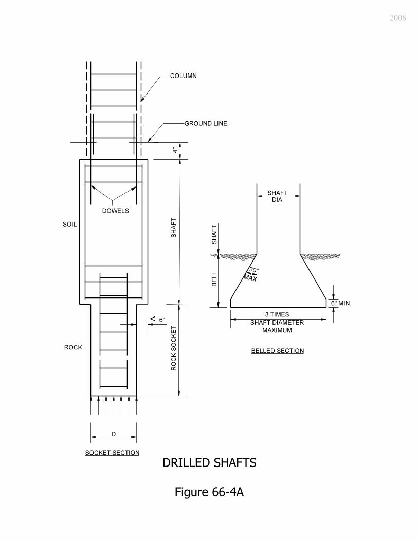
Chapter Sixty-seven discusses the design of piles for an end bent. 66-4.0 DRILLED SHAFTS Reference: Articles 5.7.4, 10.8 The following will apply to the design of drilled shafts. 1. Usage. Drilled shafts may be considered where a deep foundation is required but piles
are unsatisfactory due to obstructions, noise, vibrations, voids, or steeply dipping rock. Drilled shafts may be an economical alternative to driven piles where the use of cofferdams is anticipated. Drilled shafts should also be considered to resist large lateral or uplift loads where deformation tolerances are relatively small. Drilled shafts derive load resistance either as end-bearing shafts transferring load by tip resistance or as floating (friction) shafts transferring load by side resistance.
2. Socketed Shaft. A schematic drawing of a rock-socketed shaft is shown in Figure 66-4A.
Where casing through the overburden soils is required, the socket diameter should be at least 6 in. less than the inside diameter of the casing. For a shaft not requiring casing, the socket diameter may be equal to the shaft diameter.
3. Belled Shaft. Figure 66-4A also shows a belled section. In stiff, cohesive soils, an
enlarged base, bell, or underarm may be used to increase the tip bearing area to reduce unit end-bearing pressure or resistance to uplift. Where practical, extension of the shaft to a greater depth should be considered to avoid the difficulty and expense of the belled shaft.
4. Column Design. Because soft soils provide sufficient support to prevent lateral buckling
of the shaft, it may be designed according to the criteria for short columns described in of LRFD Specifications Article 5.7.4.4. If the drilled shaft is extended above ground to form a pier or part of a pier, it should be analyzed and designed as a column. The diameter of the column supported by a shaft should be smaller than the diameter of the shaft. The effects of scour around the shaft must be considered in the analysis. LRFD Specifications Article 10.7.4.2 provides criteria for determining the depth to fixity below the ground line for a shaft that extends for a portion of its length through water or air.
5. Reinforcement. Reinforcement should satisfy the requirements of LRFD Specifications
Articles 10.8.5.2, 10.8.5.3, and 10.8.5.5. 6. Acceptance Testing. The designer must work with the geotechnical engineer in
developing a special provision for acceptance of the drilled draft.
2008
66-5.0 SCOUR AND FOUNDATION CONSIDERATIONS 66-5.01 Hydraulic Considerations The prudent analysis of a bridge design requires that an assessment be made of the bridge’s vulnerability to undermining due to potential scour. Chapter Thirty-two discusses the hydraulic design of a bridge, including the hydraulic scour calculations that will significantly impact the design of its foundations. The Chapter discusses scour types (e.g., contraction, local), scour-resistant materials, analytical methods for scour evaluation, and countermeasures for alleviating potential scour. The Production Management Division’s Hydraulics Team is responsible for conducting all scour analyses in coordination with the designer for each new bridge located on a State-maintained route. The designer is responsible for the scour analysis for each local public agency bridge replacement project, or each rehabilitation project, either on or off a State-maintained route. These calculations must be approved by the Hydraulics Team. Bridge-foundation scour should be designed for considering the magnitude of flood, including the 100-year (1%) event that generates the maximum scour depth. 66-5.02 Structural Considerations Reference: Articles 2.6.4.4.2, 3.7.5, 10.7.4.2, 10.8.4.2 Scour is not a limit state in the context of the LRFD Specifications. It is a change in foundation condition. All of the applicable LRFD limit states must be satisfied for both the as-built and scoured bridge-foundation conditions. The consequences of the change in foundation conditions resulting from the design flood for scour should be considered at all applicable strength- and service-limit states. The design flood for scour is the more severe of the 100-year flood or an overtopping flood of lesser recurrence. The consequences of the change in foundation conditions resulting from the check flood for scour should be considered at the extreme-event limits. The check flood for scour should not exceed the 500-year flood or an overtopping flood of lesser recurrence. Spread footings should be used only where the stream bed is extremely stable below the footing and where the spread footing is founded at a depth below the maximum scour computed in Section 32-6.07. Footings may be founded above the scour elevation where they are keyed into non-erodible rock.
2008
The pile cap for a deep foundation, driven-open-pile bent, or drilled shaft, should be located such that the top of the cap is below the estimated contraction scour depth. A lower elevation should be considered where erosion or corrosion could damage the piles or shafts. Where the cap cannot be located below the maximum scour depth, the loss of soil surrounding the deep foundation results in piles or shafts with unbraced lengths equal to the length of pile or shaft exposed by the scour, plus an estimated depth to fixity. The depth to fixity should be determined as specified in LRFD Article 10.7.4.2 for driven piles, or Article 10.8.4.2 for drilled shafts. The piles or shafts exposed by scour must be designed structurally as unbraced-length columns according to LRFD Section 5 for a concrete foundation, or Section 6 for a steel foundation. Unscoured piles or shafts can be considered in structural design as continuously-braced columns.
2008
FOUNDATION REVIEW Date:
TO:
Geotechnical Services Office Manager FROM: , Designer [INDOT location] [consultant] Route: Des. No.: Structure No.: Over: Construction Project No.: It is recommended that the following foundation(s) be used for the structure identified above. Support 1 2 3 4
Type
Size
Design Load
Ultimate Load
Min. Pile Tip Elev. for Scour
Pile Tips Yes No
Yes No
Yes No
Yes No
Bottom of Footing Elevation
Top of Footing Elevation
The structure is on piles, so the Pile Loading for Geotechnical Testing chart is attached. Yes No N/A Other: Approved by: _________________________ Date: (signed) Geotechnical Engineer Reviewed by: _________________________ Date: (signed) Reviewer, INDOT [consultant] Reviewed by: _________________________ Date: (signed) Structural Services Manager
2008
2008
2008
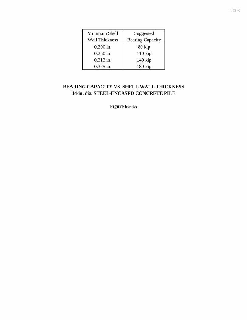
Minimum Shell Wall Thickness
Suggested Bearing Capacity
0.200 in. 0.250 in. 0.313 in. 0.375 in.
80 kip 110 kip 140 kip 180 kip
BEARING CAPACITY VS. SHELL WALL THICKNESS 14-in. dia. STEEL-ENCASED CONCRETE PILE
Figure 66-3A
2008

Minimum Length, ft Pile Size Clay Sand
HP 10 30 25 HP 12 35 25 HP 14 40 30
CFT 14 50 35
MINIMUM PILE LENGTH
Figure 66-3A(1)
2008
2008
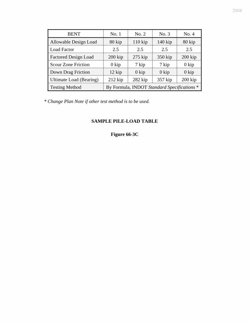
BENT No. 1 No. 2 No. 3 No. 4 Allowable Design Load 80 kip 110 kip 140 kip 80 kip Load Factor 2.5 2.5 2.5 2.5 Factored Design Load 200 kip 275 kip 350 kip 200 kip Scour Zone Friction 0 kip 7 kip 7 kip 0 kip Down Drag Friction 12 kip 0 kip 0 kip 0 kip Ultimate Load (Bearing) 212 kip 282 kip 357 kip 200 kip Testing Method By Formula, INDOT Standard Specifications *
* Change Plan Note if other test method is to be used.
SAMPLE PILE-LOAD TABLE
Figure 66-3C
2008

Project Size
Cost of Piling Recommend
Type of Analysis* Recommended
Cost of Analysis Safety Factor
Small Below $100,000 Dynamic formula,
No test n/a 2.5
Medium $100,000 ≤ Cost ≤ $500,000
Dynamic Pile- Load Test
5% to 10% of piling cost
2.0
Large Over $500,000
Dynamic Pile- Load Test Static Pile- Load Test
5% maximum of piling cost
2.0
*See INDOT Standard Specifications for contractor requirements.
SPECIFICATION OF LEVEL OF PILE TESTING
Figure 66-3D
2008
2008