2009:033 civ master's thesis a study of automatic
TRANSCRIPT

2009:033 CIV
M A S T E R ' S T H E S I S
A study of automatic translationof MATLAB code to C code using
software from the MathWorks
Alexander Vikström
Luleå University of Technology
MSc Programmes in Engineering Computer Science and Engineering
Department of Computer Science and Electrical EngineeringDivision of Computer Science
2009:033 CIV - ISSN: 1402-1617 - ISRN: LTU-EX--09/033--SE


ABSTRACT
An evaluation of code generation products from the MathWorks was made to see if they
could benefit Autoliv Electronics. Autoliv Electronics wants to generate C code from the
MATLAB language instead of having to do a manual translation which was both time-
consuming and error-prone. The conclusion was that in some situations these products
would contribute to the algorithm development process while in others they would not.
One situation where automatic code generation did contribute to the development pro-
cess was when generating reference floating-point C code. The generated reference code
would serve as a functionality reference when writing the optimized C code for the hard-
ware. However, the option of generating fixed-point C code from a fixed-point MATLAB
implementation was not considered to contribute to the algorithm development process.
A more extensive testing could reveal more situations where automatic MATLAB to
C generation would be beneficial.
iii


PREFACE
This thesis project is the final part of the educational program in Computer Engineer-
ing at Lulea University. The work has been carried out at Autoliv Electronics AB in
Mjardevi, Linkoping. I would like to take this opportunity to first and foremost thank
my advisor Stefan Johansson at Autoliv Electronics and my technical coach Fredrik Rodin
at the MathWorks. I would also like to thank Marcus Lundagards and Lars Furedal at
Autoliv Electronics for valuable discussions and everyone else who has contributed to
this thesis work.
Alexander Vikstrom
v


CONTENTS
Chapter 1: Introduction 1
1.1 Autoliv Electronics . . . . . . . . . . . . . . . . . . . . . . . . . . . . . . 1
1.2 Problem Area . . . . . . . . . . . . . . . . . . . . . . . . . . . . . . . . . 1
1.3 Purpose . . . . . . . . . . . . . . . . . . . . . . . . . . . . . . . . . . . . 2
1.4 Delimitations . . . . . . . . . . . . . . . . . . . . . . . . . . . . . . . . . 2
Chapter 2: Theory 5
2.1 Products From the MathWorks . . . . . . . . . . . . . . . . . . . . . . . 5
2.2 Defining Code Readability . . . . . . . . . . . . . . . . . . . . . . . . . . 17
2.3 Fixed-Point Arithmetics . . . . . . . . . . . . . . . . . . . . . . . . . . . 20
Chapter 3: Method 23
3.1 Selection of MATLAB Algorithms . . . . . . . . . . . . . . . . . . . . . . 23
3.2 MATLAB and Embedded MATLAB . . . . . . . . . . . . . . . . . . . . 26
3.3 Creating Simulink models . . . . . . . . . . . . . . . . . . . . . . . . . . 27
3.4 Converting From Floating-Point to Fixed-Point . . . . . . . . . . . . . . 31
3.5 Generating C code . . . . . . . . . . . . . . . . . . . . . . . . . . . . . . 34
3.6 Qualitative Investigation of Code Readability . . . . . . . . . . . . . . . 38
Chapter 4: Evaluation 41
4.1 Functionality . . . . . . . . . . . . . . . . . . . . . . . . . . . . . . . . . 41
4.2 Readability Evaluation . . . . . . . . . . . . . . . . . . . . . . . . . . . . 41
4.3 Modularity . . . . . . . . . . . . . . . . . . . . . . . . . . . . . . . . . . 47
4.4 Embedded MATLAB Limitations . . . . . . . . . . . . . . . . . . . . . . 48
Chapter 5: Discussion 51


CHAPTER 1
Introduction
1.1 Autoliv Electronics
Autoliv is a worldwide leader in automotive safety, a pioneer in both seatbelts and airbags,
and a technology leader with the widest product offering for automotive safety.
All the leading automobile manufacturers in the world are customers of Autoliv. They
service them from 80 subsidiaries and joint ventures in 30 countries.
Autoliv Electronics is part of Autoliv and has operations primarily in France, Sweden,
the U.S., Japan and China with approximately 1.500 employees in total. [1]
1.2 Problem Area
The task of translating programming code from the MATLAB language to the C language
for implementation in hardware has always been time consuming and cumbersome. The
most common way of doing this is to manually translate line by line of MATLAB code
thus having to consider factors like memory allocation and execution speed manually.
Considering how the MATLAB code is designed, this is a procedure that often requires
a lot of man hours.
There are several benefits of starting an algorithm development process in MATLAB and
then ending it in C. MATLAB offers a wide selection of functions, automatic memory
handling of variables and other interesting features that allows the engineer to focus
on the function of the algorithm instead of the practical implementation. MATLAB
also simplifies the algorithm testing process with its ability to easily produce plots and
reports. When the MATLAB code is ready to be tested in hardware such as a Digital
1

2 Introduction
Figure 1.1: the Autoliv algorithm development process
Signal Processor (DSP), a translation of the MATLAB code to a language more suitable
for hardware implementation such as C is needed. This is the time consuming and error
prone part of the algorithm development process which is the basis for this thesis.
1.3 Purpose
The purpose of this thesis work is to investigate the possibility of automating the pro-
cess of translating the MATLAB code into C, resulting in a faster and more efficient
development process. If the C-reference code could be automatically translated from the
MATLAB reference code, then the development process would speed up significantly.
1.4 Delimitations
The main delimitation is that I have chosen not to include any other software products
for automatic translation than the ones supplied by the MathWorks. The reason for this
is twofold. First of all, it would take a lot of time to examine all available equivalent
products. Second of all, products from MathWorks are already in use by Autoliv Elec-
tronics and therefore would make them easy to incorporate.
The products available from the MathWorks which will be examined are:
• MATLAB and Embedded MATLAB
• Simulink

1.4. Delimitations 3
• Real-Time Workshop and Real-Time Workshop Embedded Coder
• Fixed-Point Toolbox
These products are to be tested and evaluated using two different algorithms. The reason
for choosing just two algorithms is simply due to the time constraint of the thesis. When
it comes to the characteristics of the chosen algorithms, one is chosen for its simplicity
and the other is chosen to test some of the limitations of the products. The chosen
algorithms are the Sobel filter and the Kalman filter.
1.4.1 Evaluation Delimitations
Several different key points influences the evaluation of a programming code. From
Autoliv Electronics point of view, these are the key points that the evaluation should
consist of:
1. Correct functionality
2. Level of readability
3. Limitations
4. Modularity
Correct functionality means that the generated C code should behave exactly as the orig-
inal MATLAB code. When presented with the same inputs it should produce the same
outputs. The code also has to have a certain level of readability to be able to function as
a reference code between the MATLAB implementation and the final embedded C code.
The readability is a major time factor when reference code needs to be optimized for the
target platform.
An important question is if there are any limitations put on the algorithm development
process. Do these tools have any negative influences on the creativity of the algorithm
developers?
The possibility to generate C code modules that can be used in other frameworks is
also interesting.


CHAPTER 2
Theory
2.1 Products From the MathWorks
The MathWorks is a multi-national corporation currently employing more than 2000 peo-
ple worldwide. They are one of the leading suppliers of software for technical computing
and model-based design. Their main products are MATLAB and Simulink. According to
the MathWorks these products are used by over 1,000,000 engineers in over 100 countries.
The MathWorks produces software for technical computing and Model-Based Design for
engineers, scientists, mathematicians, and researchers. Their two core products are MAT-
LAB, used for performing mathematical calculations, analyzing and visualizing data, and
writing new software programs; and Simulink, used for modeling and simulating complex
dynamic systems, such as a vehicle’s automatic transmission system. They also produce
more than 90 additional tools for specialized tasks such as processing images and signals
and analyzing financial data [2].
The products from the MathWorks are extensively used by Autoliv worldwide.
2.1.1 MATLAB
MATLAB, short for MATrix LABoratory, is a numerical computing environment as well
as a high-level programming language. It performs many computationally intensive tasks
with considerable higher speed than other programming languages.
MATLAB is used in areas like signal and image processing, communications, control
design, test and measurement, financial modeling and analysis, and computational bi-
5

6 Theory
Figure 2.1: MATLAB
ology. Add-on toolboxes (collections of special-purpose MATLAB functions, available
separately) extend the MATLAB environment to solve particular classes of problems in
these application areas [3]. Figure 2.1 shows a screenshot from the MATLAB environ-
ment.
The toolboxes of current interest for this thesis have a certain order of dependency.
MATLAB is needed for Simulink, Simulink is needed for Real-Time Workshop and so
on (see figure 2.2). The fixed-point toolbox is an optional part and only needed if fixed-
point implementations are desired. To be able to use EMLC (the Embedded MATLAB
to C code generator) a Simulink license is needed even though the Simulink graphical
environment is never used nor desired.

2.1. Products From the MathWorks 7
Figure 2.2: The toolbox dependencies
2.1.1.1 Fixed-Point Toolbox
The fixed-point toolbox for MATLAB provides the user with the ability to create fixed-
point objects for facilitating the design of fixed-point algorithms and fixed-point arith-
metics.
The main function of the fixed-point toolbox is the ability to create objects called fi-
objects. These are objects containing information about the specific bit size and arith-
metic rules of a fixed-point number. The fi-object can itself be divided into two objects,
the fimath object and the numerictype object. These objects contain enough informa-
tion to define all relevant fixed-point arithmetics for a fi-object [4]. Figure 2.3 shows Pi
defined as a fi-object.
The most important settings of the fimath and numerictype objects relating to this
thesis are:
The fimath object
Round mode - Defines how the number should be rounded to the nearest available
fixed-point representation.

8 Theory
Figure 2.3: Pi as a fi-object in Fixed-Point Toolbox
Overflow mode - Defines how a number outside the fixed-point range should be han-
dled.
Product mode - Defines how the product data type is determined.
Maximum product word length - Defines the maximum number of bits that can
represent a product of two numbers.
Sum mode - Defines how the sum data type is determined.
Maximum sum length - Defines the maximum number of bits that can represent a
sum of two numbers.
The numerictype object
Data type mode - Defines what data type and type of scaling is associated with the
fi-object. The default value and the value used when working on this thesis is

2.1. Products From the MathWorks 9
the fixed-point data type with binary point scaling. This means that the scaling is
defined by a pre-determined word length and fraction length.
Signed - Defines whether or not the number should be an unsigned or a signed data
type. A signed number has the ability to represent negative numbers as well as
positive numbers.
Word length - Defines the total number of bits that represents the number.
Fraction length - Defines the number of bits that represents the fractional (decimal)
part of the number.
2.1.1.2 Embedded MATLAB
Embedded MATLAB is a subset of the MATLAB language which supports efficient code
generation for deployment in embedded systems and acceleration of fixed-point algo-
rithms. It supports over 270 operators and functions from the MATLAB language and
over 100 functions from the fixed-point toolbox. Embedded MATLAB can be described
as a less high-level programming language than the MATLAB programming language [5].
There are a number of functions exclusively created for the Embedded MATLAB subset.
These functions can only be used when the %#eml tag is present in the beginning of the
m file. They are:
eml.allowpcode - Enables the generation of P-files which provides intellectual property
protection for source M-files.
eml.ceval - Executes external C function inside the Embedded MATLAB code.
eml.cstructname - Specifies the name of a certain structure in the C code. This can
be used to avoid obfuscated structure names.
eml.extrinsic - Defines certain functions in the Embedded MATLAB code as extrinsic.
Meaning that these functions will only be executed when run in MATLAB. They
will be excluded when generating C code.
eml.inline - Controls whether or not the Embedded MATLAB function should be in-
lined when generating C code. Available options are always, never and default.
Reduced inlining provides higher readability after C code generation.
eml.nullcopy - Used to preallocate memory with type, size and complexity without
initializing values.
eml.opaque - Used to declare a variable in the future generated C code. But does not
instantiate the variable. For instance, a variable can be declared with eml.opaque
and then instantiated with eml.ceval.
10 Theory
eml.ref - Passes arguments by reference to functions called by eml.ceval.
eml.rref - Same as eml.ref but passes the arguments as read-only input.
eml.target - Determines Embedded MATLAB code generation target.
eml.unroll - Used to unroll for-loops for optimization.
eml.wref - Same as eml.ref but passes the arguments as read-only input.
Embedded MATLAB Limitations
The following features available in MATLAB are not supported in the Embedded MAT-
LAB subset [5].
Cell arrays - These data types that are available in MATLAB has the ability to store
different data types in the same array. The same array could for instance include one
string, one double and one integer. This is not supported in Embedded MATLAB.
Command/function duality - Embedded MATLAB supports only function style syn-
tax while MATLAB also supports command style syntax.
Dynamic variables - The size of all allocated memory in the MATLAB code has to
be known at compile time. This information is needed for the MATLAB to C
compiler EMLC to be able to optimize the C code for speed and memory handling.
Embedded MATLAB does not allow variables that changes size during the program
run time.
Global variables - It is not possible to declare variables as global in Embedded MAT-
LAB.
Java - MATLAB has the support for the Java language. Embedded MATLAB does not.
Matrix deletion - The possibility in MATLAB of deleting entries in a matrix is not
available in Embedded MATLAB since deleting an entry results in a change of
variable size.
Nested functions - Function declarations inside functions are not allowed in Embedded
MATLAB.
Objects - The object-orientation support in MATLAB is not available in Embedded
MATLAB.
Sparse matrices - MATLAB has a way of handling sparse matrices to reduce the
amount of memory needed to be allocated. This is not supported in Embedded
MATLAB.

2.1. Products From the MathWorks 11
Try/catch statements - The error handling try/catch statements are not supported
in Embedded MATLAB.
An example of the dynamic variable limitation is the declaration of matrices. In MAT-
LAB matrices can be altered by adding or deleting elements without any limitations. In
Embedded MATLAB a matrix must be pre-allocated without any possibilities to change
the dimensions after the allocation. Other examples are all functions in MATLAB which
return matrices of an arbitrary size. Since there is no way of knowing in advance what
dimensions the return value will have, it is impossible to allocate static memory for the
return value. These functions are therefore not supported in Embedded MATLAB.
2.1.2 Simulink
Simulink is an add-on for MATLAB which gives the user a graphical model-based design
environment. This can be used for simulating, testing and implementing dynamic and
embedded systems. See figure 2.4.
Figure 2.4: Simulink
Different block diagrams are used to represent a process. This could for example be a
signal processing process where a picture is used as an input signal, processed through
different image processing blocks such as rotation or blurring and then ending with the
resulted output. Figure 2.5 gives an example of how Simulink blocks can represent an
image process consisting of a rotation and a blur filter. Figure 2.6 shows the input image
and the resulting output image from this process.
Simulink is a multi-domain modeling tool thus making it capable of modelling complex
systems such as whole bridges, cars or airplanes.

12 Theory
Figure 2.5: A Simulink block process
Figure 2.6: To the left: The input image. To the right: The resulting output image, rotated andblurred.
2.1. Products From the MathWorks 13
2.1.2.1 Real Time Workshop
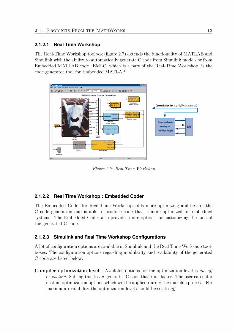
The Real-Time Workshop toolbox (figure 2.7) extends the functionality of MATLAB and
Simulink with the ability to automatically generate C code from Simulink models or from
Embedded MATLAB code. EMLC, which is a part of the Real-Time Workshop, is the
code generator tool for Embedded MATLAB.
Figure 2.7: Real-Time Workshop
2.1.2.2 Real Time Workshop : Embedded Coder
The Embedded Coder for Real-Time Workshop adds more optimizing abilities for the
C code generation and is able to produce code that is more optimized for embedded
systems. The Embedded Coder also provides more options for customizing the look of
the generated C code.
2.1.2.3 Simulink and Real Time Workshop Configurations
A lot of configuration options are available in Simulink and the Real Time Workshop tool-
boxes. The configuration options regarding modularity and readability of the generated
C code are listed below.
Compiler optimization level - Available options for the optimization level is on, off
or custom. Setting this to on generates C code that runs faster. The user can enter
custom optimization options which will be applied during the makefile process. For
maximum readability the optimization level should be set to off.

14 Theory
Comments - Configuring Simulink to include comments in the generated C code greatly
enhances readability. Different type of comments are available for configuration.
However, the most important configuration for comments is the include comments
check box. With this box checked, core comments like function comment blocks
and signal commenting are utilized by the C code generator.
Identifier format control - The identifier formats can be altered to look a special
way. However, these settings are not applicable on the identifiers in the Embedded
MATLAB function block. They are only affecting the identifiers in the Simulink
environment.
Custom code - Custom C code can be added in the source file or the header file. It
can also create an initialization and/or termination function with custom C code.
The TLC can also be used to alter the look of the code. See the next section for a short
explanation.
2.1.2.4 The TLC
TLC is short for Target Language Compiler and is an advanced feature in Real Time
Workshop that lets the user further customize the C code generated from Simulink blocks.
The use of the TLC to customize code is outside the scope of this thesis but an option
worth mentioning. See figure 2.8 for a overview of the Simulink code generation process
and where the TLC comes in [6].

2.1. Products From the MathWorks 15
Figure 2.8: The TLC part of the code generation process in Simulink
2.1.3 EMLC
EMLC, short for Embedded MatLab to C, is the function used to generate C code from
the MATLAB language. This function provides some compilation options located in the
MATLAB configuration objects named emlcoder.MEXConfig, emlcoder.CompilerOptions,
emlcoder.RTWConfig and emlcoder.HardwareImplementation. This is a list of all config-
uration options for EMLC [7].
Compiler optimization level - Available options for the optimization level is on, off
or custom. Setting this to on generates C code that runs faster. The user can enter
custom optimization options which will be applied during the makefile process. For
maximum readability the optimization level should be set to off.
Makefile generation - Whether or not a makefile should be created.
Code generation report - Option for generating a HTML report of the generated
code.
Identifier naming rules - The only things that can be set is the maximum length
of the identifiers and reserved names. The maximum length could influence code
readability if the generator decides to generate identifiers that are too long.

16 Theory
Generate code only - This is an option for generating code only without trying to
compile it.
Include custom C code - Custom C code can be added in the source file or the header
file. It can also create an initialization and/or termination function with custom C
code.
Verbose build - Displays the code generation process for debugging purposes.
Target function library - This option gives the user the ability to decide a target func-
tion library of a specific hardware processor or specific C standard. The available
target libraries are:
• C89/C90 (ANSI)
• C99 (ISO)
• GNU99 (GNU)
• TI C28x (ISO)
• TI C28
• TI C55x (ISO)
• TI C55x
• TI C62x (ISO)
• TI C62x
• TI C64x
• TI C64x+
• TI C67x
The ability to use target function libraries can greatly enhance the optimization of
the C code.
Function in-lining control - The options to define the maximum size of an in-lined
function could enhance readability. Setting the maximum size to a high number
reduces in-lining and enhances readability.
Maximum stack usage - Sets the maximum amount of memory available on the stack.
When the stack is full memory allocations will be made on the heap. This option
is important if the target hardware has a limited stack memory size.
Constant folding timeout - The maximum number of executions permitted when ap-
plying an optimization technique called constant folding.
Saturate on integer overflow - Incorporates controls in the generated code to detect
integer overflow or underflow.

2.2. Defining Code Readability 17
Embedded hardware device specifications - Has the options to define the data type
sizes, byte ordering and how to round signed integer division.
2.2 Defining Code Readability
To be able to use the generated code as a reference for further implementation, the
code must be readable and understandable by the engineers working on the software
implementation for the hardware platform. According to [8], reading code is the most
time-consuming component of all maintenance activities. This could really lead to a
bottle-neck in the development process.
Code readability is not an easy subject to digest since the opinions differ. There are
however some common guidelines affecting code readability that many seem to agree on.
Logical Structure and Layout
Probably the most important aspect of code readability is the structure and layout of
the code. It is important for the reader to be able to follow the flow of the code. There-
fore the layout is used to emphasize the logical structure of the code [9]. The layout is
something which only has an aesthetic impact on the code. The compiler does not care
at all what the indentation or spacing of the code looks like.
The logical structure however has some impact on the level of optimization but most
of the time it has an even bigger impact on the level of readability. One example of
improving the logical structure to enhance readability is to divide the code into sub-
functions. The natural path of the program flow should be clear and obvious so dividing
the code into functions helps the reader to follow the program flow. These functions
should have obvious names, be short and should preferably perform one task each. This
way the name of the function can provide the reader with a clear description of what this
function does [10].
There are several different kinds of coding style standards. Some common ones are
Indian Hill, GNU and MISRA. There are also a lot of companies that use styles that
are internal and company specific. The most important thing is not which style is used,
the important thing is to choose a style and then continue to follow it consistently [9, 11].
Some pointers relating to structure and layout which enhances readability are
• Usage of descriptive types helps the reader to understand the code. I.e const for
constants, unsigned for non-negatives [10].
• Constants should also be used instead of ”magic numbers”. Instead of the line if

18 Theory
(counter == 76), the programmer should declare a constant with the description
of the number 76. For instance const sizeT bananasPerCake = 76; and then using
the constant bananasPerCake instead of 76. In that case the reader understands
why the condition specifically contains the number 76 and it is thus no longer a
magic number [10].
• The source code should be self-documenting [11], thus decreasing the amount of
comments needed. It is better to rewrite bad code than to try to fix it with
comments [12].
• Important code should be emphasized so that the attention of the reader is drawn
to it. One statement or declaration per line is also preferable to enhance clarity
and to make important information stand out [10].
• Nested conditional statements are often difficult to follow, this should be avoided
if possible [10].
• All related information grouped in one place is preferable. This eliminates having
to jump back and fourth when trying to understand the code [10].
Style Consistency
Consistency of style is more important than the details of the style itself [11]. Different
styles in a project can give the reader the impression that the source files do not belong
together. It could also give an unprofessional feeling about the code [10].
Naming of Variables and Functions
The naming of identifiers have an enormous impact on the comprehensibility of a soft-
ware system [13]. The names of identifiers like variables, functions, type, namespaces
and file names gives the reader a lot of information of the functionality of the code.
While good naming enhances the readability, bad naming can almost make a program
impossible to understand. For example, a well named function can eliminate the need of
any commenting while a badly named function without any comments could totally fool
the reader. Thinking he or she knows exactly what the function does when in fact its
functionality is totally opposite its naming. A bad named function confuses the reader
not only when reading the function declaration, but also when reading the function calls
to that specific function. According to [14] the quality of a well named identifier can be
divided into the following:
Descriptive - The name should describe what a specific function does or what kind
of value is stored in a specific variable. Good naming examples are the function
convolve2D() and the variable numberOfRows while bad examples are the function
foo() and the variable number.

2.2. Defining Code Readability 19
Technically correct - The programming language could restrict how an identifier can
be named. Some names are always reserved and certain characters are forbidden.
Examples of reserved identifier names in C are numbers, conditional statements
like if, else and the character !.
Idiomatic - The use of idioms of the specific programming language is preferred when
naming identifiers. Seeing identifiers named conventionally gives the reader a sense
of familiarity. A programming idiom example for the C language is when writing
i++; instead of i = i + 1;.
Appropriate - An appropriate named identifier is of correct length and tone. Abbrevi-
ations are often very hard for the reader to understand, it is better to use natural
language words when, for instance, describing the functionality of a function. Using
stupid or silly names can give the code an unprofessional feel and make the reader
doubt the competence of the author. An example of this is naming a variable blah.
According to [13] identifiers account for 72% of the source code characters. There is no
doubt that a source code with consistently bad named identifiers greatly decreases the
readability.
Use of Comments
The main thing to have in mind when discussing comments is that comments should not
replace bad code. Comments are used to make good, understandable code even better.
[12] points out some important things to consider when discussing comments:
• The quality of the comments are more important than the quantity.
• Good comments explain why, not how.
• Code should not be duplicated in the commenting.
• Code should not be replaced by comments.
• Comments should be clear and concise.
• Functions should start with a block comment.
• Comments should be indented the same way as the rest of the code.
• Comments should be used in a way that reads naturally. Before a function, not
below.

20 Theory
The Readers Prior Knowledge of the Program
How familiar the reader is with the general function of the code is something that makes
it easier to understand the code [11]. A programmer with years of experience working
with Kalman filters will have a less hard time understanding a specific Kalman filter
function than an equally skilled programmer with less or no experience of Kalman filters.
2.3 Fixed-Point Arithmetics
When talking about how computers represent numbers you can distinguish between fixed-
point representation and floating-point representation. A common way of representing
numbers in computer science is by the binary number system. A floating point represen-
tation of the number y consists of a mantissa and an exponent with the equation
y = M ∗ 2E. (2.1)
In this case M is the mantissa and E is the exponent, which in binary number system
would be represented as M.E where the radix point is the point separating the mantissa
from the exponent. The name ”floating-point” refers to the radix point being able to
move freely between the mantissa and the exponent thus creating a larger number range.
The real position of the radix point is encoded into the binary representation of the
number.
The problem with floating-point representation is that a Floating Point Unit (FPU) is
needed in addition to the processor. One way to solve this is to use a processor with an
integrated FPU. This significantly raises the price of the hardware and is therefore not a
good option when large quantities of the product is to be manufactured. Another option
is to emulate the FPU in software which significantly slows down the calculations. The
solution to this is to use fixed-point notation instead of floating-point. This eliminates the
need of an FPU or any kind of floating-point emulation and can therefore considerably
cut the cost of the hardware.
The difference between fixed-point and floating-point is where the radix point is located.
As the name tells us, in fixed-point notation the position of the radix point is fixed
whereas in floating-point notation the position of the radix point is adjustable. When
choosing the position of the radix point in fixed-point notation you have to decide between
large resolution or large number range. Considering a number represented by eight bits
in fixed-point notation, if the radix point is set at the position directly to the left of
the first bit then all eight bits will represent the decimal part of the number, giving this
specific number x a range of
0 6 x 68∑
i=1
2−i < 1. (2.2)

2.3. Fixed-Point Arithmetics 21
This assumes an unsigned fixed-point number. The more general equation for the range
of an unsigned fixed-point number is
0 6 x 6 2m − 2−f , (2.3)
where m is the magnitude or the positive part of the number while f is the fractional
or decimal part of the number. When dealing with negative numbers, the use of two’s
complement arithmetic is necessary. This means that the first bit will indicate whether
the number is positive or negative giving the number a range of
−2m−1 6 x 6 2m−1 − 2−f . (2.4)
The problem that occurs when trying to convert a floating-point algorithm to fixed-point
is how to choose where the radix point should be set for all the numbers. Naturally a loss
in precision will occur and the risk for overflow and/or underflow will also be a factor to
take into consideration. Overflow and underflow happens when a number exists outside
its range. This can be handled in two different ways. Either the number is saturated,
which means that if it is an overflow the number will get its maximum range value or if
it is an underflow, it will get its minimum range value.
The other way of handling this problem is to wrap the number, which means that it is
set as the modulus of the number and its maximum. The modulus of the number in this
case is what is left when it is divided with its maximum range.
The work of converting code from floating-point to fixed-point is cumbersome and often
very difficult. Nevertheless it is necessary when the target hardware consists of a fixed-
point processor without an FPU. [15, 16]

CHAPTER 3
Method
3.1 Selection of MATLAB Algorithms
Two algorithms were chosen for the evaluation. The idea was to use one algorithm which
was rather small and simple, and another algorithm which was a little more complicated
and would propose a bigger challenge for the code generator. Both algorithms had to
be of the image processing kind since a lot of image processing work is being done at
Autoliv Electronics.
For this purpose the algorithms chosen were the Sobel operator and the Kalman filter.
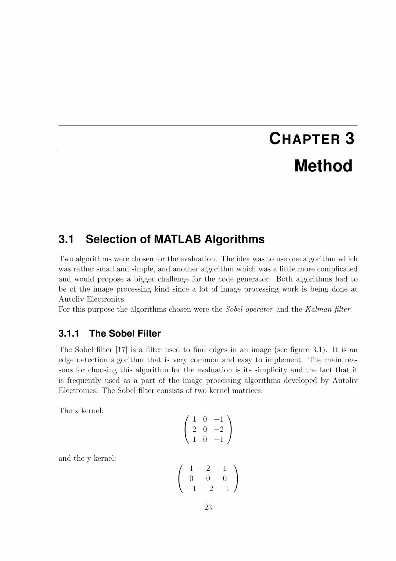
3.1.1 The Sobel Filter
The Sobel filter [17] is a filter used to find edges in an image (see figure 3.1). It is an
edge detection algorithm that is very common and easy to implement. The main rea-
sons for choosing this algorithm for the evaluation is its simplicity and the fact that it
is frequently used as a part of the image processing algorithms developed by Autoliv
Electronics. The Sobel filter consists of two kernel matrices:
The x kernel: 1 0 −1
2 0 −2
1 0 −1
and the y kernel: 1 2 1
0 0 0
−1 −2 −1
23
24 Method
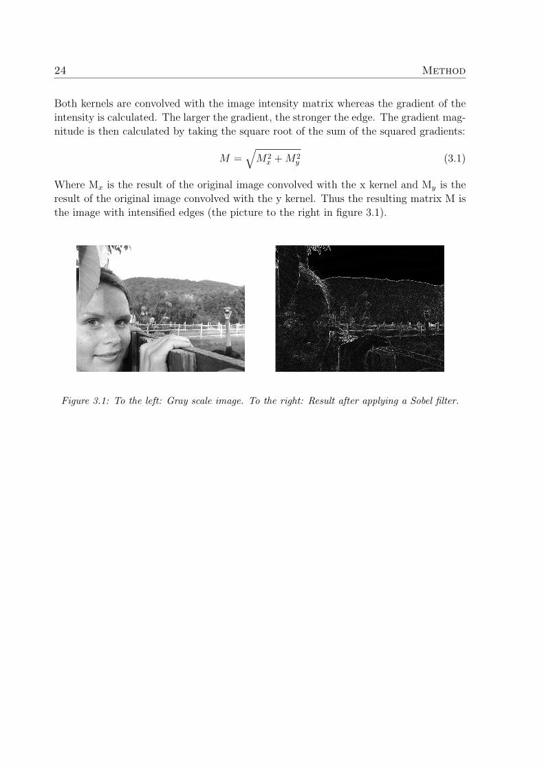
Both kernels are convolved with the image intensity matrix whereas the gradient of the
intensity is calculated. The larger the gradient, the stronger the edge. The gradient mag-
nitude is then calculated by taking the square root of the sum of the squared gradients:
M =√
M2x + M2
y (3.1)
Where Mx is the result of the original image convolved with the x kernel and My is the
result of the original image convolved with the y kernel. Thus the resulting matrix M is
the image with intensified edges (the picture to the right in figure 3.1).
Figure 3.1: To the left: Gray scale image. To the right: Result after applying a Sobel filter.

3.1. Selection of MATLAB Algorithms 25
3.1.2 The Kalman Filter
The Kalman filter is a signal processing filter which is able to estimate the state of a dy-
namic system when the input variables are noisy [18]. This algorithm is generally used at
Autoliv Electronics to track objects through several consecutive frames. This algorithm
contains a lot of matrix operations and therefore makes it an interesting algorithm to
evaluate because C is generally a bad language for doing these kinds of operations. For
instance, one line of matrix operations in MATLAB could correspond to more than 50
lines of C code. This algorithm was also selected for its use of sine and cosine as well as
its use of matrix inversions. This was interesting to see how the C code generator would
handle. Figure 3.2 shows an example of how a Kalman filter predicts the real value from
a number of observations containing a random noise.
Figure 3.2: An example of the output of a Kalman filter

26 Method
3.2 MATLAB and Embedded MATLAB
The Sobel implementation was written directly in Embedded MATLAB without prob-
lems. Mostly due to the fact that the MATLAB function conv2(), which can be used
to convolve 2-dimensional matrices, was compliant with the Embedded MATLAB subset.
A simple version of the Extended Kalman filter was provided by Autoliv Electronics.
It was originally written in MATLAB so an effort of converting the MATLAB code to
Embedded MATLAB was made. However, not much work had to be done when convert-
ing the Kalman filter from MATLAB to Embedded MATLAB. Only two changes had to
be made:
1. The %#eml tag always has to be present in the beginning of an Embedded MAT-
LAB file and therefore had to be added.
2. The line hk = zeros(3,1); had to be added to preallocate memory statically instead
of dynamically for a matrix. In this case hk is defined as a 3 by 1 matrix containing
only zeros.
The selected algorithms were easily converted. Therefore a conversion was carried out
by an Autoliv engineer to convert a larger MATLAB program to Embedded MATLAB
for the purpose of then generating C code. This process was closely followed and then
evaluated regarding the effort needed, the imposed restrictions on the implementation
and the achieved result.
A valuable help when converting MATLAB to Embedded MATLAB or when using the
Embedded MATLAB subset to develop from scratch is the M-Lint tool. This is a real-time
code checker which is integrated in the MATLAB editor. M-Lint warns by underlining
non-compliant code and gives an explanation when the mouse pointer is hovered above
the underlining.
M-Lint does not give warnings for all non-compliant code but it still provides valuable
help when programming.
The process of converting MATLAB code to Embedded MATLAB can be summarized
in three steps:
1. Define data types
2. Allocate memory statically instead of dynamically
3. Replace functions not supported by Embedded MATLAB

3.3. Creating Simulink models 27
3.3 Creating Simulink models
The Simulink standard block set contains a block named Embedded MATLAB Function
(figure 3.3). In this block it is possible to insert Embedded MATLAB code and connect
it with other Simulink blocks.
Figure 3.3: The Embedded MATLAB Function Block
A question that arose was which storage class to be used when defining the inputs.
There are four different options:
Auto - The default storage class. This is the storage class to choose when the generated
C code does not need to be interfaced with external code. Input states defined as
Auto storage class is stored as a member of the Dwork state vector.

28 Method
ExportedGlobal - The input state is stored in a global variable which is exported by
the main header file.
ImportedExtern - The input state is declared as an extern variable in a header file.
ImportedExternPointer - The same as the ImportedExtern storage class but the input
state is declared as a pointer.
The Simulink Sobel Model
Different implementations were considered when creating the Simulink Sobel model. The
first implementation that was carried out consisted of arithmetic Simulink blocks like add
and square root as well as convolve. However, the approach of building an algorithm from
scratch with Simulink blocks was considered to be too time-consuming and non-efficient
to be of interest for algorithm implementation at Autoliv Electronics. The possibility of
creating a Sobel model using a specific edge detection block from the image processing
toolbox end generating code from this was also discussed. It was concluded however,
that no one of these methods would be a desirable work process at Autoliv Electronics.
Algorithms at Autoliv Electronics are created in the MATLAB language so the most
interesting solution would be to use these MATLAB algorithms directly in Simulink.
The Sobel model in Simulink was therefore created using the Embedded MATLAB func-
tion block together with external constants feeding the function block with the Sobel
kernels. The Sobel kernels kernel x and kernel y were declared externally in the MAT-
LAB workspace as seen in figure 3.4 and their storage classes were set to ExportedGlobal.
This resulted in the same C kernel variable names as the kernels in the model after gen-
erating C code. When first trying to declare the kernels inside the Embedded MATLAB
Function non-intuitive names were given to the kernel variables by the C generator, thus
decreasing readability. For modularisation purposes the storage class of the input image
was set to ImportedExternPointer. Because of the dynamic memory restrictions, the di-
mensions and data type of the input image had to be set. The dimensions of the image
was set to 640 * 480 pixels. A floating 32 bit data type precision was defined by Simulink
since the hardware settings for the Embedded Coder was set to a 32-bit embedded pro-
cessor.
The Embedded MATLAB Function block as seen in figure 3.5 simply contains a call
to the same Embedded MATLAB compliant Sobel function used when generating code
with the EMLC compiler.

3.3. Creating Simulink models 29
Figure 3.4: The Simulink Sobel Model
Figure 3.5: Inside the Embedded MATLAB Sobel Function Block
The Simulink Kalman Model
A first attempt of creating a Kalman filter in Simulink resulted in a very complex model
consisting of buses, timers and arithmetic operations. A more simple and understandable
model was then provided by the MathWorks. This model was used for C code generation

30 Method
and evaluation. As can be seen in figure 3.6 the measurements for the filter is read from
the MATLAB workspace and the state signals are read from a Simulink bus object.
Figure 3.6: The Top-Level of the Kalman Model
The settings struct is also read from the MATLAB workspace where it is created as a
Simulink bus object with the Simulink.BusElement function. All signals and objects
read from the MATLAB workspace are created by a script. This script is called from
the model initialization function set in the model properties. The Embedded MATLAB
block of the Kalman filter can be seen in figure 3.7.
The Embedded MATLAB function block consists of calling the Kalman initialization
function to get the recursion starting and then calling the Kalman filter function. The
tracks object is declared as persistent to keep it in memory between the function calls.
The code inside the Embedded MATLAB block can be seen in figure 3.8.

3.4. Converting From Floating-Point to Fixed-Point 31
Figure 3.7: The Kalman Filter Embedded MATLAB Block
Figure 3.8: Inside the Embedded MATLAB Kalman Function Block
3.4 Converting From Floating-Point to Fixed-PointThis work was only done for the Embedded MATLAB code. However it is worth men-
tioning that Simulink provides floating-point to fixed-point semi-automatic conversion

32 Method
by use of the Fixed-Point Advisor tool. This tool is not evaluated in this thesis but a
short description can be found in section 3.4.3.
3.4.1 Sobel
The convolution function conv2 used in the floating-point version did not have support
for the MATLAB fixed-point objects (fi-objects). Therefore the conv2 function had to
be rewritten for this purpose.
When the Sobel filter was faced with finding edges in an image consisting of integer
data types only one fi-object had to be created. All variables except the fi-object could
be declared as simple integers. The fi-object was needed when a square root had to be
calculated (which is not supported for integer data types). The Embedded MATLAB
code doing this was:
fiObject = fi(sobelX * sobelX + sobelY * sobelY, 0, 32, 0);
outImage(currentImRow, currentImCol) = sqrt(fiObject);
This corresponds to calculating the gradient magnitude as described in equation 3.1 in
section 3.1.1.
When wanting the Sobel filter to handle images of floating data types all variables used
in calculations had to be converted to the fi-object. First of all the input image had to
be converted to the fi-object. This means that some information could be lost depending
on the range of the image and the bit size of the fi-object. In this case all fi-objects were
given an unsigned 32-bit fi-object size. Further optimization could be made to decrease
the amount of bits needed for the variables but it was considered to be outside the scope
of this thesis.
3.4.2 Kalman
The conversion from floating to fixed-point of the Kalman filter proved to be a cumber-
some task. Lookup tables had to be implemented for the sine and cosine operations.
Forward and backward substitution processes had to be implemented for the matrix left
division calculations.
Matrix left division (also known as backslash-division) can be explained with the fol-
lowing equations:
Ax = B (3.2)
x = A\B (3.3)
x = A−1B (3.4)

3.4. Converting From Floating-Point to Fixed-Point 33
The backslash character in equation 3.3 denotes a left division of matrices A and B. This
is the same as multiplying the inverse matrix of A with the matrix B (as seen in equation
3.4).
The conversion of the Kalman filter from floating-point to fixed-point was provided by
an expert at the MathWorks.
3.4.3 The Simulink Fixed-Point Advisor Tool
The Fixed-Point Advisor is a tool that can be used to be guided through all the steps of
converting a Simulink model from floating-point to fixed-point.
As can be seen in figure 3.9 the conversion process are divided into four main tasks:
1. Prepare model for conversion
2. Prepare for data typing and scaling
3. Perform data typing and scaling
4. Prepare for code generation
The user is guided through these tasks with feedback and suggestions on how to complete
the tasks. When all tasks in the Fixed-Point Advisor are completed, an initial scaling
will exist for the fixed-point system. Further scaling optimizations can then be made
with the Fixed-Point Tool.

34 Method
Figure 3.9: The Simulink Fixed-Point Advisor
3.5 Generating C code
A number of default C files are generated by EMLC and Simulink. The EMLC files that
are generated for both the Sobel and the Kalman functions are:
rt nonfinite.c (and .h) - Initializes C corresponding objects for the MATLAB Inf (in-
finity) and NaN (Not a Number) objects.
rtGetInf.c (and .h) - Declarations for the Inf object.
rtGetNaN.c (and .h) - Declarations for the NaN object.
rtwtypes.h - This header file contains the data type specifications and their type defi-
nitions.
modelName initialize.c (and .h) - When adding a custom code initialisation func-
tion in the EMLC configuration, this is where the custom code is put by the code
generator.

3.5. Generating C code 35
modelName terminate.c (and .h) - When adding a custom code termination func-
tion in the EMLC configuration, this is where the custom code is put by the code
generator.
modelName types.h - Provides forward declarations of data structures and type def-
initions.
The files generated by Simulink which are common for both the Sobel model and the
Kalman model are:
rtwtypes.h - This file contains the data type specifications and their type definitions.
Identical to the rtwtypes.h generated by EMLC.
modelName types.h - Contains forward declaration of data structures and type defi-
nitions. The same as generated by EMLC. The settings, signals and tracks structs
for the Kalman model are type defined in this file.
modelName private.h - Defines parameters and data structures private to the gener-
ated code. Storage classes defined as ImportedExtern and ImportedExternPointer
are declared in this file. This is where the input image pointer is declared in the
Sobel function.
(Where modelName is replaced by the name of the model (i.e mySobel))
Sobel by EMLC
Several different combinations of options and different MATLAB Sobel implementation
were tried out to find a generated C code with high readability. The main problem of this
simple function was the naming of the kernel variables in the C code. In MATLAB the
variables are named sobelKernelX and sobelKernelY. The first tries of code generation
resulted in these variables named eml dv0 and eml dv1 which reduced readability. This
was solved by declaring the kernels as workspace variables and then letting them be a
part of the arguments in the function call. So instead of the MATLAB Sobel function
declaration being:
function outImage = mySobel(inImage)
the function was declared as:
function outImage = mySobel(inImage, sobelKernelX, sobelKernelY)
This resulted in a correspondence between the kernel variable names in MATLAB and C.
One negative effect of this was, as mentioned before, that the kernels had to be declared
in the MATLAB workspace. However, not having to hard code the kernels in the function

36 Method
could also benefit the re-usability of the MATLAB code.
The EMLC command used to generate the final C code from the Sobel function was:
emlc mySobel -report -c -T RTW -eg{im, sobelKernelX, sobelKernelY}
Where im was the image matrix of the input image to be convolved with the kernels
sobelKernelX and sobelKernelY. All three already declared in the MATLAB workspace.
Except for the files mentioned above the generated files were:
conv2.c (and .h) - The convolution function corresponding to the conv2 function in
MATLAB. Convolutes two matrices of fixed dimensions.
mySobel.c (and .h) - The source Sobel function.
sqrt.c (and .h) - Returns the square root of the input argument.
Kalman by EMLC
The Embedded MATLAB Kalman implementation consisted of two Embedded MATLAB
files and one MATLAB script. The script was used to define the settings and start signals
for the Kalman filter. These variables were passed to the first Embedded MATLAB file
(KalmanFilterInit.m) which was used to initialize the states of the Kalman filter. The
signals returned from the initialization were passed to the second Embedded MATLAB
file (KalmanFilterEM.m) which consisted of the actual Kalman filter algorithm, thus
starting the recursive process.
Since there were two Embedded MATLAB files somewhat independent of each other,
two C code generations, one for each file, had to be made. The EMLC commands were:
emlc KalmanFilterInit -c -report -T RTW:EXE -eg{z, settings};emlc KalmanFilterEM -c -report -T RTW:EXE -eg{tracks, z, signals, set-
tings};
Except for the files mentioned above the generated files were:
KalmanFilterInit.c (and .h) - The source file of the Kalman filter initialisation.
KalmanFilterEM.c (and .h) - The source file of the Kalman filter function.
rt pow snf.c (and .h) - Contains a function returning the resulting power of a number.
Takes a number and the specific power as input arguments. Also contains guards
against domain errors and non-finite numbers.

3.5. Generating C code 37
Sobel by Simulink
The Embedded MATLAB implementation of Sobel was called from a Embedded MAT-
LAB Simulink block and then generated into C code. Different C code was generated
depending on what storage class was chosen for the input image. For the Auto and
ExportedGlobal storage classes a section of memory is initialized in C with the row:
(void) memset(inImage,0,307200*sizeof(real32 T));
and then declared as
real32 T inImage[307200];
For the ExportedGlobal storage class the input image is also exported as
extern real32 T inImage[307200];
in the header file. For the ImportedExtern and ImportedExternPointer storage classes
the input image is declared extern with
extern real32 T inImage[307200];
and
extern real32 T *inImage;
respectively. The dimensions of the input image was set to 640 * 480 which is why the
size of the array became 640 * 480 = 307200 elements.
Except for the files mentioned the following file was generated:
mySobel.c (and .h) - The source file of the Sobel function.
Kalman by Simulink
The Embedded MATLAB implementation of the Kalman filter was called from an Em-
bedded MATLAB simulink block. The Simulink model of the Kalman filter consisted of
a loop which started out with a call to the Embedded MATLAB implementation of the
Kalman initialisation and continued with a call to the Embedded MATLAB implemen-
tation of the Kalman filtering. The Embedded MATLAB block was used to generate C
code.
Except for the files mentioned above the generated files were:
Kalman.c (and .h) - The source file of the whole Kalman filter function. Contains
both the initialization process and the filtering process.
rt pow.c (and .h) - Contains a function returning the resulting power of a number.
Takes a number and the specific power as input arguments.

38 Method
3.5.1 About MEX code
EMLC has the ability to generate Embedded MATLAB MEX code which consists of C
code with a wrapper making it possible to run directly in MATLAB. This is especially
useful for functions which runs faster when implemented in C instead of MATLAB. For
instance functions containing a lot of for-loops or fixed-point implementations. This
MEX-wrapped C file can be transferred between work stations containing the same ver-
sion of MATLAB. Thus eliminating the need of a Real-Time Workshop license on all
work stations wanting to use the MEX file.
When running the fixed-point version of the Sobel filter and using an image with the
dimension 640 * 480 pixels and the 32 bit integer data type, the calculation time in
MATLAB was 1671 seconds. After generating a MEX function of this implementation
and feeding it with the same image the calculation time was reduced to 4 seconds. So in
this case, by generating a MEX function the calculation time was reduced 418 times!
Consequently MEX files are a great solution for speeding up MATLAB test cases con-
sisting of calculations that are difficult for MATLAB to handle.
The emlmex() function also has the ability explained above. This function is available
when either Simulink or the Fixed-Point Toolbox are installed.
3.6 Qualitative Investigation of Code Readability
Ten engineers working at Autoliv Electronics with different knowledge and experience of
C and the specific algorithms received automatic generated C code from the MATLAB
versions of the floating-point implementations of the Sobel operator as well as the Kalman
filter. To simulate a real-world environment they received both the MATLAB code as
well as the C code by e-mail. They were then asked to look at the code for approximately
30 minutes and evaluate it with respect to the following questions:
• How difficult was it to understand the code?
• What can you say about the readability?
• Mention something or somethings which makes the code more readable or less
readable.
• Could this code serve as reference in an algorithm development process? Justify
your answer.
A goal when choosing test subjects was to try to get a spread of their experiences with
MATLAB, C and the Sobel and Kalman filters. The experience spread can be seen in

3.6. Qualitative Investigation of Code Readability 39
table 1.
Little Moderate Lots
MATLAB 0 2 8
C 3 3 4
Sobel filter 2 3 5
Kalman filter 4 4 2
Table 1: The experience spread of the test subjects
There was a three day deadline after which the answers were collected through interviews.
The total compiled result was used in the evaluation of the code generators ability to
produce readable code.


CHAPTER 4
Evaluation
4.1 FunctionalityThe most important factor when automatically generating C code from MATLAB is that
the C code generated works exactly the way the MATLAB code does.
The functionality evaluation for the EMLC generated C code was carried out by cre-
ating a C framework for the Sobel C code as well as for the Kalman C code. After
generating randomized input data, this data was fed to the MATLAB function and the
output was saved. The same randomized input data was then fed to the corresponding
C function and the output was saved. The output from the MATLAB function and the
output from the C function were compared. After establishing that the outputs matched,
the conclusion could be drawn that the two functions had the same functionality. How-
ever, most of the responsibility for the functionality of the C code to correspond to the
functionality of the Embedded MATLAB code lies with the MathWorks. The scope of
this thesis regarding functionality is a simple functionality test for evaluating these par-
ticular algorithms. It is assumed that the MathWorks have done extensive testing to
assure the general functionality of the code generator.
4.2 Readability EvaluationThe readability is analyzed from these different steps:
1. Discussion of common points regarding code readability retrieved from external
sources like articles, books and the Internet.
2. Coding rules used at Autoliv Electronics.
41

42 Evaluation
3. Individual opinions from a number of Autoliv engineers.
4.2.1 Theoretical Discussion
4.2.1.1 EMLC
Common
The generated code is always divided and ordered after the following commented sections:
• Include files
• Type Definitions
• Named Constants
• Variable Declarations
• Variable Definitions
• Function Declarations
• Function Definitions
This gives the reader a clear and intuitive arrangement of the code and enhances the read-
ability. The style consistency is very good. The same style (i.e spacing and indentation)
is used everywhere in the generated code.
Sobel
The names of the variables are consistent with the original MATLAB names except for
the added eml tag. The tag makes the code cluttered and is negative to the readability.
The convolution part of the Sobel function is implemented in a single C file and then
called from the Sobel function, thus making the Sobel function smaller and easier to read.
The conv2.c file generated from the MATLAB convolution function has a starting com-
ment block containing the only function explanation:
Embedded MATLAB Coder code generation for M-function ’conv2 ’
This does not explain the conv2 function satisfactorily. A more informative comment
block is needed. The same applies to the sqrt.c file and all C files created directly from
corresponding MATLAB functions. Also, the naming of the variables in conv2.c are
not informative. The variable names are eml jc, eml j, eml jp1, eml ja1, eml ic, eml i,
eml ip1, eml ia1, eml s, eml ja, eml jb, eml ia, giving the reader no help of understanding
the code from the naming. However, the presence of a more informative comment block

4.2. Readability Evaluation 43
would give the reader an understanding of the function which significantly reduces the
need for the code to be understandable at a lower level.
The row size and column size of the image are magic numbers (see chapter 2.2). These
should be declared as constants and named in a way that describes what they represent.
Overall this generated function of Sobel is small, simple and readable.
Kalman
Structs are type defined using a random 22 letter generated unique name to avoid con-
flicting names. This severely reduces readability. An example of a struct type definition
is sjYbIs6FPxxuTKjQ5VzQKU whose readability effect on the code speaks for itself.
A solution for this was found after the evaluation. The Embedded MATLAB function
eml.cstructname() is able to define the name of the C generated structs. The lines:
eml.cstructname(tracks, ’kfTracks’);
eml.cstructname(signals, ’kfSignals’);
eml.cstructname(settings, ’kfSettings’);
were added in the beginning of the Kalman Embedded MATLAB file. After C code gen-
eration the structs were named kfTracks, kfSignals and kfSettings which greatly improved
readability.
The start comment block which is placed at the beginning of the Embedded MATLAB
function is not positioned at the same place in the generated C file. Instead it is posi-
tioned after the variable declarations. This has a negative effect on the readability since
a start comment block is always positioned at the beginning of the function. However the
in-line comments are placed at the same place in the C code as in the original MATLAB
code thus enhancing readability.
A good solution to the start comment block position problem could be to define a com-
mand in MATLAB that specifies the comment as being a start block comment. The
compiler could then use this information as it sees fit. Preferably incorporating those
comments into the start comment block of the C file.
The C code generated from the MATLAB matrix operations should definitely be sepa-
rated and put in an external function. This way they can be called from the Kalman
main function to make the Kalman function smaller and more readable. Just by looking
at the matrix operations, which are represented by nested for loops in C, it is almost
impossible to understand what is done.

44 Evaluation
4.2.1.2 Simulink
Common
The main difference between the code generated by EMLC and the code generated by
Simulink is the real time framework added by Simulink. This framework consists of
initialization and step function with possibilities to attach a timer. This makes the code
a little less readable but the core function of Sobel and Kalman is the same as the code
generated by EMLC.
Sobel
Many of the same problems regarding readability exists in the Simulink version of Sobel
as in the EMLC version.
Kalman
The same problem regarding the position of the start comment block exists in the
Simulink generated C code as in the EMLC generated C code from the Kalman fil-
ter. Also the same problem regarding the naming of the type defined structs returns.
The same solution to the struct naming problem as mentioned above was not applica-
ble on the Simulink model. This problem was instead solved by defining the structs as
Simulink.Bus objects in the MATLAB script where the workspace variables are defined.
An example of this procedure in MATLAB is:
BusSignals = Simulink.Bus;
BusElement v = Simulink.BusElement;
BusElement v.Name = ’v’;
BusElement v.SampleTime = settings.Ts;
BusSignals.Elements = [BusElement v];
The example only shows how to add the bus element v to the signals bus. All variables
of the signals struct were of course added to the Simulink bus as bus elements.
4.2.2 Coding rules
This is a listing of Autoliv coding rules regarding readability followed by comments on
how the generated C code complies with the rules.
Identifiers shall be named using camel case - Meaning that lower case letters shall
be used except for the first letter of each word (i.e NumberOfBananas). Also no
underscore characters are allowed. Since most but not all identifier names are

4.2. Readability Evaluation 45
intact when generating C code, the programmer is responsible for not breaking this
particular rule. However, the addition of the eml tag to all identifiers makes it
impossible to follow this rule. Identifiers originally created by EMLC do not follow
this rule.
Sensible, descriptive names shall be used for identifiers - Again this is a rule of
which the responsibility lies with the original programmer. However, identifiers
created by EMLC do not follow this rule.
Variable names shall be prefixed to indicate their type - This rule defines the data
type name and the variable prefix name for a number of data types. Custom data
type names are definable in Simulink but not in EMLC. The variable prefix has to
be added by the programmer for identifier names that are kept after code genera-
tion. Settings exist in Simulink for controlling the format of the identifier naming
so that this rule may be followed.
Indentations shall be done with 3 spaces per level - The generated C code is in-
dented with two characters per level for both EMLC and Simulink versions. There
are no available settings for the indentation size.
Braces shall be lined up with the enclosing statement or declaration - This rule
is not followed. The code generator uses K&R style brace positioning meaning that
start braces are positioned directly after and on the same line number as the con-
ditional line.
Function parameters shall be lined up with one parameter per line - This rule
is not followed and there exists no possibility of configuration.
Loop and conditional statements shall have brace enclosed sub-statements - This
rule is followed.
Each statement shall be placed on a line of its own - This rule is followed.
Declare each objects in a separate declaration - This rule is followed.
Lines shall not exceed 80 characters - This rule is followed.
Do not use tabs - This rule is followed.
Do not use function calls inside another function call - This rule is followed. Even
if this rule is broken in the Embedded MATLAB code, it is corrected by the code
generator.
Comments shall be placed above the commented line, indented identically - This
rule is followed.
46 Evaluation
Define the appearance of the C source and header files with a template - The
emlcoder.RTWConfig object contains settings for adding custom C code for the C
source and header files. However, the added code is positioned after the file com-
ment block and #include declarations generated by EMLC. In Simulink however, it
is possible to define the templates of the generated C files using the TLC. Simulink,
but not EMLC, has therefore the ability to follow this rule.
Conclusions
According to the MathWorks [19] there is really no present need for the adding of the
eml tag, so hopefully this will be removed in future versions of EMLC. Since the same
Embedded MATLAB code of the Sobel and Kalman filters are used when generating
code with Simulink, the problem persists. However, code generated from Simulink with
no relation to Embedded MATLAB has no addition of the eml tag.
When comparing the abilities of EMLC and Simulink to follow these rules, Simulink
has the advantage. Much because the possibility to access the TLC (see chapter 2) for
configuring the way the generated code will look.
Customers of Autoliv Electronics also have conditions regarding what the source code
should look like regarding style. However, less restrictions are put on third-party code so
a question then arises whether or not generated code could be thought of as third-party
code. If that is the case then there would be less restrictions on generated code, but the
factor of readability and its effects on the development process is still an issue.
4.2.3 Qualitative Investigation
The test subjects of the qualitative readability evaluation had the following to say about
the readability of the generated C code:
Pros
• The structure of the code is generally good and consistent which facilitates read-
ability.
• The variables in MATLAB generally keep their names in the C code.
• The comments in MATLAB are automatically added to the C code and is generally
positioned at the correct place.

4.3. Modularity 47
Cons
• The structures have strange names, they are given randomly selected unique names.
Makes the code harder to read.
• The pre-written conv2.c should contain more comments and more informative vari-
able names.
• The eml tag of every variable is unnecessary and makes the code more cluttered.
• Matrices are declared in a fashion that makes it more difficult to follow.
• More spacing would improve readability.
• The C code generated from the Simulink model in-lines all functions. This is bad
for readability.
Conclusions
The test subjects were positive to the idea of using the C code as a testing and comparison-
based reference code but they were interested in how the generated C code would look
like when generating code from an algorithm more complex and consisting of more code
than the Sobel and Kalman filters. Their opinion were also that if the code should be
used as a starting point for writing optimized C code a greater readability had to be
achieved, especially in the case regarding the Kalman filter. As expected the Kalman
filter proved to be a difficult algorithm for the code generator.
It also became clear that the test subjects with more experience of C and the Kalman
filter experienced the generated C code as more readable while test subjects with less
experience of C or the Kalman filter experienced the generated C code as less readable.
4.3 Modularity
The purpose of modularity is to make reusable code by creating code modules to be
used in other contexts and frameworks. To be able to generate C code from a commonly
used MATLAB function that could easily be implemented in other C related frameworks
would be a powerful tool for testing and possibly even for use in production code.
As mentioned in the evaluation, the possibility of modularization seems to be greater
for the EMLC generated code than for the C code generated from Simulink. In the
evaluation cases of Sobel and Kalman the Simulink code generator embeds the original
function into a framework of step functions and initializations whereas the EMLC gener-
ated code is almost good to go for usage in whatever context one could see fit. However,

48 Evaluation
a good understanding of the framework generated by Simulink makes the process of ex-
tracting the important parts far more simple.
A serious problem that arises regarding modularization has to do with the memory han-
dling of input variables. A common task in image processing is to take an arbitrary sized
part of an image and perform calculations on it. Say for instance that these calculations
have a purpose of finding edges inside this image patch by applying a Sobel filter. The
way to solve this problem in MATLAB code is to simply create a function that takes an
arbitrary sized image patch, performs a convolution with a Sobel kernel and returns the
edges from the patch. This is not possible to implement in Embedded MATLAB code
since the size of the patch must be known at compilation time. This impairs modularity
since there is no way of generating C code that works on all possible patch sizes. One
solution to this is to take the whole image as an input argument together with the coor-
dinates defining the patch. The apparent negative side of this solution is that more data
needs to be stored in memory which could be an important factor when dealing with
embedded hardware.
The row major/column major difference between MATLAB and C could be a prob-
lem regarding modularity. MATLAB saves its matrices in column-major order while C
saves its matrices in row-major order. If generated C code using row-major ordering of
matrices are to be integrated into a system using column-major ordering, problems will
occur. This is a factor to consider and have in mind.
4.4 Embedded MATLAB Limitations
4.4.1 Opinions from MATLAB Developers
Since Embedded MATLAB imposes some restrictions on the algorithm development pro-
cess, it is very interesting to know the opinions of those who regularly use the MATLAB
programming language.
A generation of C code from a set of Autoliv developed MATLAB functions that are
used regularly for image processing was done. Opinions derived from this work were:
• M-Lint only gives real-time warnings for some functions not supported by Em-
bedded MATLAB. Further development of M-lint to give additional warnings or
maybe suggestions is welcome. However, according to the MathWorks [19] M-Lint
is constantly being improved and this specific issue is probably going to be fixed in
the near future.
• Some algorithms have to be designed in C style, for instance when the dynamic
memory allocation limitations prevents the programmer of using practical MAT-

4.4. Embedded MATLAB Limitations 49
LAB functions. Somewhere there is a limit when it would be more practical to
implement an algorithm directly in C instead of trying to write C-like Embedded
MATLAB code.
• It puts more demand on the memory handling design early in the process.
• It would be a good idea to list all regularly used MATLAB functions which are
not supported by Embedded MATLAB together with an alternative solution for
Embedded MATLAB. As in the case with the arbitrary image patches (see section
4.3).

CHAPTER 5
Discussion
Would it benefit Autoliv to start using products from the MathWorks for automatic C
code generation? First of all one should consider all the pros and cons.
Pros
• The ability to speed up test cases by running them on generated C code instead of
MATLAB code.
• Quickly generate C code to use as reference code when comparing manually opti-
mized C code with the reference code.
• Quickly generate C code to be used in prototype hardware for quick prototyping.
• Quick generation of C code modules for use as part of production code.
Cons
• The cost of acquiring licenses from the MathWorks for using their products.
• The overhead learning time needed before being able to use the products.
• Having to write C style code in MATLAB. Thus limiting the free algorithm devel-
opment process.
• Having to consider the memory handling aspects could make the algorithms more
complicated.
• Using the Fixed-Point Toolbox can be difficult when the algorithm development
team has limited knowledge of the hardware.
51

52
There are three different steps of the possibility of Autoliv Electronics using the code
generation products from the MathWorks.
1. The first step is to generate a reference code which will be used for comparing the
functionality to a hand-written optimized C code. The generated reference code
will serve as a functionality reference when writing the optimized C code for the
hardware.
2. The second interesting step is expanding the generation process to generating Fixed-
Point C code.
3. The third step is to generate production code ready to be used in hardware such
as DSP:s.
The most interesting step for Autoliv Electronics is the first one. This step puts minimal
limitations on the algorithm development team and also requires relatively small efforts
when converting existing MATLAB code to Embedded MATLAB. The use of the Fixed-
Point Toolbox puts too much limitations on the algorithm development team. They do
not have the skills necessary to be able to define all the bit sizes of the fi-objects which
would render their fixed-point MATLAB model less useful. This also means that the
generation of fixed-point production code is difficult. Most of the time production code
requires a fixed-point implementation, either defined in Embedded MATLAB or later
defined in the generated C code. However, the generated C code lacks the readability
necessary to do a C code conversion from floating to fixed-point. There could be a pos-
sibility of generating small snippets of code to be used in production code. There is
also a possibility to create floating-point production code. A change in organisation by
combining the algorithm development team with the software team in the future could
result in the possibility of using the fixed-point toolbox to create MATLAB fixed-point
implementations.
All these possibilities are something that should be investigated further in the future.

REFERENCES
[1] Autoliv. Autoliv webpage, January 2009. http://www.autoliv.com.
[2] The MathWorks. About the mathworks, December 2008.
http://www.MathWorks.com/company/aboutus/.
[3] The MathWorks. Matlab - the language of technical computing, December 2008.
http://www.MathWorks.se/products/MATLAB/.
[4] The MathWorks. Fixed-Point Toolbox User´s Guide, October 2008.
[5] The MathWorks. Embedded MATLAB User´s Guide, March 2008.
[6] The MathWorks. Target Language Compiler User´s Guide, October 2008.
[7] The MathWorks. Real-Time Workshop User´s Guide, October 2008.
[8] R.P.L Buse and W.R Weimer. A metric for software readability. 2008.
[9] P Goodliffe. Code Craft : The Practice of Writing Excellent Code, chapter 2, pages
23–37. No Starch Press, Incorporated, San Fransisco, 2006.
[10] P Goodliffe. Code Craft : The Practice of Writing Excellent Code, chapter 4, pages
57–72. No Starch Press, Incorporated, San Fransisco, 2006.
[11] J.L Elshoff and M. Marcotty. Improving computer program readability to aid mod-
ification. Communications of the ACM, 25(8):512–521, August 1982.
[12] P Goodliffe. Code Craft : The Practice of Writing Excellent Code, chapter 5, pages
73–88. No Starch Press, Incorporated, San Fransisco, 2006.
[13] F. Deissenboeck and M. Pizka. Concise and consistent naming. In Program Com-
prehension, 2005. IWPC 2005. Proceedings. 13th International Workshop on, pages
97–106. IWPC, May 2005.
53

54
[14] P Goodliffe. Code Craft : The Practice of Writing Excellent Code, chapter 3, pages
39–55. No Starch Press, Incorporated, San Fransisco, 2006.
[15] M.B Kraeling. Fixed-point math in time-critical applications. In Wescon/96, pages
587–593. Wescon, Oct 1996.
[16] R. Yates. Fixed-point arithmetics: An introduction. August 2007. A technical
reference.
[17] P.M Mather. Computer Processing of Remotely-Sensed Images - An Introduction,
chapter 7, pages 194–195. John Wiley Sons, 2004.
[18] P.S Maybeck. Stochastic Models, Estimation and Control, chapter 1, pages 1–15.
Academic Press, 1979.
[19] F. Rodin. The mathworks. E-mail correspondence and discussions.