2015 imc2015 international mechanical code iii preface introduction internationally, code officials...
TRANSCRIPT


2015 IMC®
INTERNATIONALMechanical Code®
CODE ALERT!Sign up now to receive critical code updates and free access to videos,
book excerpts and training resources.
Signup is easy, subscribe now! www.iccsafe.org/alerts
Copyright © 2014 ICC. ALL RIGHTS RESERVED. Accessed by Scott Twogood on Feb 23, 2017 7:46:51 AM pursuant to License Agreement with ICC. No further reproduction ordistribution authorized. ANY UNAUTHORIZED REPRODUCTION OR DISTRIBUTION IS A VIOLATION OF THE FEDERAL COPYRIGHT ACT AND THE LICENSEAGREEMENT, AND SUBJECT TO CIVIL AND CRIMINAL PENALTIES THEREUNDER.

2015 International Mechanical Code®
First Printing: May 2014
ISBN: 978-1-60983-479-1 (soft-cover edition)ISBN: 978-1-60983-478-4 (loose-leaf edition)
COPYRIGHT © 2014by
INTERNATIONAL CODE COUNCIL, INC.
Date of First Publication: May 30, 2014
ALL RIGHTS RESERVED. This 2015 International Mechanical Code® is a copyrighted work owned by the International Code Council, Inc. Without advance written permission from the copyright owner, no part of this book may be reproduced, distrib-uted, or transmitted in any form or by any means, including, without limitation, electronic, optical or mechanical means (by way of example, and not limitation, photocopying, or recording by or in an information storage retrieval system). For information on permission to copy material exceeding fair use, please contact: Publications, 4051 West Flossmoor Road, Country Club Hills, IL 60478. Phone 1-888-ICC-SAFE (422-7233).Trademarks: “International Code Council,” the “International Code Council” logo and the “International Mechanical Code” are trademarks of the International Code Council, Inc.
PRINTED IN THE U.S.A.
Copyright © 2014 ICC. ALL RIGHTS RESERVED. Accessed by Scott Twogood on Feb 23, 2017 7:46:51 AM pursuant to License Agreement with ICC. No further reproduction ordistribution authorized. ANY UNAUTHORIZED REPRODUCTION OR DISTRIBUTION IS A VIOLATION OF THE FEDERAL COPYRIGHT ACT AND THE LICENSEAGREEMENT, AND SUBJECT TO CIVIL AND CRIMINAL PENALTIES THEREUNDER.

2015 INTERNATIONAL MECHANICAL CODE iii
PREFACE
IntroductionInternationally, code officials recognize the need for a modern, up-to-date mechanical codeaddressing the design and installation of mechanical systems through requirements emphasizingperformance. The International Mechanical Code, in this 2015 edition, is designed to meet theseneeds through model code regulations that safeguard the public health and safety in all communi-ties, large and small.
This comprehensive mechanical code establishes minimum regulations for mechanical systemsusing prescriptive and performance-related provisions. It is founded on broad-based principles thatmake possible the use of new materials and new mechanical designs. This 2015 edition is fully com-patible with all of the International Codes (I-Codes) published by the International Code Council(ICC), including the International Building Code, International Energy Conservation Code, Interna-tional Existing Building Code, International Fire Code, International Fuel Gas Code, InternationalGreen Construction Code, International Plumbing Code, ICC Performance Code, International Pri-vate Sewage Disposal Code, International Property Maintenance Code, International ResidentialCode, International Swimming Pool and Spa Code, International Urban-Wildland Interface Code
and International Zoning Code.
The International Mechanical Code provisions provide many benefits, among which is the modelcode development process that offers an international forum for mechanical professionals to dis-cuss performance and prescriptive code requirements. This forum provides an excellent arena todebate proposed revisions. This model code also encourages international consistency in the appli-cation of provisions.
DevelopmentThe first edition of the International Mechanical Code (1996) was the culmination of an effort initi-ated in 1994 by a development committee appointed by the ICC and consisting of representatives ofthe three statutory members of the International Code Council at that time, including: Building Offi-cials and Code Administrators International, Inc. (BOCA), International Conference of Building Offi-cials (ICBO) and Southern Building Code Congress International (SBCCI). The intent was to draft acomprehensive set of regulations for mechanical systems consistent with and inclusive of the scopeof the existing model codes. Technical content of the latest model codes promulgated by BOCA,ICBO and SBCCI was utilized as the basis for the development. This 2015 edition presents the codeas originally issued, with changes approved through the ICC Code Development Process through2013. A new edition such as this is promulgated every 3 years.
This code is founded on principles intended to establish provisions consistent with the scope of amechanical code that adequately protects public health, safety and welfare; provisions that do notunnecessarily increase construction costs; provisions that do not restrict the use of new materials,products or methods of construction; and provisions that do not give preferential treatment to par-ticular types or classes of materials, products or methods of construction.
AdoptionThe International Code Council maintains a copyright in all of its codes and standards. Maintainingcopyright allows ICC to fund its mission through sales of books, in both print and electronic formats.The International Mechanical Code is designed for adoption and use by jurisdictions that recognizeand acknowledge the ICC’s copyright in the code, and further acknowledge the substantial sharedvalue of the public/private partnership for code development between jurisdictions and the ICC.
The ICC also recognizes the need for jurisdictions to make laws available to the public. All ICCcodes and ICC standards, along with the laws of many jurisdictions, are available for free in a non-downloadable form on the ICC’s website. Jurisdictions should contact the ICC at [email protected] to learn how to adopt and distribute laws based on the International Mechanical Code in amanner that provides necessary access, while maintaining the ICC’s copyright.
Copyright © 2014 ICC. ALL RIGHTS RESERVED. Accessed by Scott Twogood on Feb 23, 2017 7:46:51 AM pursuant to License Agreement with ICC. No further reproduction ordistribution authorized. ANY UNAUTHORIZED REPRODUCTION OR DISTRIBUTION IS A VIOLATION OF THE FEDERAL COPYRIGHT ACT AND THE LICENSEAGREEMENT, AND SUBJECT TO CIVIL AND CRIMINAL PENALTIES THEREUNDER.

iv 2015 INTERNATIONAL MECHANICAL CODE
MaintenanceThe International Mechanical Code is kept up to date through the review of proposed changes sub-mitted by code enforcing officials, industry representatives, design professionals and other inter-ested parties. Proposed changes are carefully considered through an open code developmentprocess in which all interested and affected parties may participate.
The contents of this work are subject to change through both the code development cycles andthe governmental body that enacts the code into law. For more information regarding the codedevelopment process, contact the Codes and Standards Development Department of the Interna-tional Code Council.
While the development procedure of the International Mechanical Code ensures the highestdegree of care, the ICC, its members and those participating in the development of this code do notaccept any liability resulting from compliance or noncompliance with the provisions because the ICCdoes not have the power or authority to police or enforce compliance with the contents of thiscode. Only the governmental body that enacts the code into law has such authority.
Code Development Committee Responsibilities(Letter Designations in Front of Section Numbers)
In each code development cycle, proposed changes to this code are considered at the CommitteeAction Hearing by the International Mechanical Code Development Committee, whose action con-stitutes a recommendation to the voting membership for final action on the proposed change. Pro-posed changes to a code section that has a number beginning with a letter in brackets areconsidered by a different code development committee. For example, proposed changes to codesections that have [BG] in front of them (e.g., [BG] 309.1) are considered by the IBC — General CodeDevelopment Committee at the Committee Action Hearing.
The content of sections in this code that begin with a letter designation is maintained by anothercode development committee in accordance with the following:
[A] = Administrative Code Development Committee;
[BF] = IBC — Fire Safety Code Development Committee;
[BS] = IBC — Structural Code Development Committee;
[BG] = IBC — General Code Development Committee;
[E] = International Energy Conservation Code Development Committee;
[F] = International Fire Code Development Committee; and
[FG] = International Fuel Gas Code Development Committee.
For the development of the 2018 edition of the I-Codes, there will be three groups of code devel-opment committees and they will meet in separate years. Note that these are tentative groupings.
Copyright © 2014 ICC. ALL RIGHTS RESERVED. Accessed by Scott Twogood on Feb 23, 2017 7:46:51 AM pursuant to License Agreement with ICC. No further reproduction ordistribution authorized. ANY UNAUTHORIZED REPRODUCTION OR DISTRIBUTION IS A VIOLATION OF THE FEDERAL COPYRIGHT ACT AND THE LICENSEAGREEMENT, AND SUBJECT TO CIVIL AND CRIMINAL PENALTIES THEREUNDER.

2015 INTERNATIONAL MECHANICAL CODE v
Note: Proposed changes to the ICC Performance Code will be heard by the code development committee noted in brackets [ ]in the text of the code.
Code change proposals submitted for code sections that have a letter designation in front ofthem will be heard by the respective committee responsible for such code sections. Because differ-ent committees hold code development hearings in different years, proposals for this code will beheard by committees in both the 2015 (Group A) and the 2016 (Group B) code development cycles.
For example, every section of Chapter 1 of this code is designated as the responsibility of theAdministrative Code Development Committee, and that committee is part of the Group B codehearings. This committee will conduct its code development hearings in 2016 to consider all codechange proposals for Chapter 1 of this code and proposals for Chapter 1 of all I-Codes except theInternational Energy Conservation Code, the ICC Performance Code and the International Residen-tial Code. Therefore, any proposals received for Chapter 1 of this code will be deferred for consider-ation in 2016 by the Administrative Code Development Committee.
Another example is Section 606.4 of this code which is designated as the responsibility of theInternational Fire Code Development Committee. This committee will conduct its code develop-ment hearings in 2016 to consider code change proposals in its purview, which includes any propos-als to Section 606.4.
In some cases, another committee in Group A will be responsible for a section of this code. Forexample, Section 607 has a [BF] in front of the numbered sections, indicating that these sections ofthe code are the responsibility of one of the International Building Code Development Committees.The International Building Code is in Group A; therefore, any code change proposals to this sectionwill be due before the Group A deadline of January 2015, and these code change proposals will beassigned to the appropriate International Building Code Development Committee for consideration.
It is very important that anyone submitting code change proposals understand which code devel-opment committee is responsible for the section of the code that is the subject of the code changeproposal. For further information on the code development committee responsibilities, please visitthe ICC website at www.iccsafe.org/scoping.
Group A Codes(Heard in 2015, Code Change Proposals
Deadline: January 12, 2015)
Group B Codes(Heard in 2016, Code Change Proposals
Deadline: January 11, 2016)
Group C Codes(Heard in 2017, Code Change Proposals
Deadline: January 11, 2017)International Building Code
– Fire Safety (Chapters 7, 8, 9, 14, 26)– Means of Egress
(Chapters 10, 11, Appendix E)– General (Chapters 2-6, 12, 27-33,
Appendices A, B, C, D, K)
Administrative Provisions (Chapter 1 ofall codes except IRC and IECC, adminis-trative updates to currently referencedstandards, and designated definitions)
International Green Construction Code
International Fuel Gas CodeInternational Building Code
– Structural (Chapters 15-25, Appendices F, G,
H, I, J, L, M)International Existing Building Code International Energy Conservation CodeInternational Mechanical Code International Fire Code
International Plumbing CodeInternational Residential Code
– IRC-B (Chapters 1-10, Appendices E,F, H, J, K, L, M, O, R, S, T, U)
International Private Sewage Disposal Code
International Wildland-Urban InterfaceCode
International Property MaintenanceCode
International Residential Code– IRC-Mechanical (Chapters 12-24)– IRC-Plumbing
(Chapters 25-33, Appendices G, I, N, P)International Swimming Pool and Spa
CodeInternational Zoning Code
Copyright © 2014 ICC. ALL RIGHTS RESERVED. Accessed by Scott Twogood on Feb 23, 2017 7:46:51 AM pursuant to License Agreement with ICC. No further reproduction ordistribution authorized. ANY UNAUTHORIZED REPRODUCTION OR DISTRIBUTION IS A VIOLATION OF THE FEDERAL COPYRIGHT ACT AND THE LICENSEAGREEMENT, AND SUBJECT TO CIVIL AND CRIMINAL PENALTIES THEREUNDER.

vi 2015 INTERNATIONAL MECHANICAL CODE
Marginal MarkingsSolid vertical lines in the margins within the body of the code indicate a technical change from therequirements of the 2012 edition. Deletion indicators in the form of an arrow ( ) are provided inthe margin where an entire section, paragraph, exception or table has been deleted or an item in alist of items or a table has been deleted.
A single asterisk [*] placed in the margin indicates that text or a table has been relocated withinthe code. A double asterisk [**] placed in the margin indicates that the text or table immediatelyfollowing it has been relocated there from elsewhere in the code. The following table indicates suchrelocations in the 2015 edition of the International Mechanical Code.
Italicized TermsSelected terms set forth in Chapter 2, Definitions, are italicized where they appear in code text.Such terms are not italicized where the definition set forth in Chapter 2 does not impart theintended meaning in the use of the term. The terms selected have definitions that the user shouldread carefully to facilitate better understanding of the code.
2015 LOCATION 2012 LOCATIONNone None
�
Copyright © 2014 ICC. ALL RIGHTS RESERVED. Accessed by Scott Twogood on Feb 23, 2017 7:46:51 AM pursuant to License Agreement with ICC. No further reproduction ordistribution authorized. ANY UNAUTHORIZED REPRODUCTION OR DISTRIBUTION IS A VIOLATION OF THE FEDERAL COPYRIGHT ACT AND THE LICENSEAGREEMENT, AND SUBJECT TO CIVIL AND CRIMINAL PENALTIES THEREUNDER.

2015 INTERNATIONAL MECHANICAL CODE vii
EFFECTIVE USE OF THE INTERNATIONAL MECHANICAL CODE
The International Mechanical Code (IMC) is a model code that regulates the design and installa-tion of mechanical systems, appliances, appliance venting, duct and ventilation systems, combus-tion air provisions, hydronic systems and solar systems. The purpose of the code is to establish theminimum acceptable level of safety and to protect life and property from the potential dangersassociated with the installation and operation of mechanical systems. The code also protects thepersonnel that install, maintain, service and replace the systems and appliances addressed by thiscode.
The IMC is primarily a prescriptive code with some performance text. The code relies heavily onproduct specifications and listings to provide much of the appliance and equipment installationrequirements. The general Section 105.2 and the exception to Section 403.2 allow designs andinstallations to be performed by approved engineering methods as alternatives to the prescriptivemethods in the code.
The format of the IMC allows each chapter to be devoted to a particular subject with the excep-tion of Chapter 3, which contains general subject matters that are not extensive enough to warranttheir own independent chapter.
Chapter 1 Scope and Administration. Chapter 1 establishes the limits of applicability of thecode and describes how the code is to be applied and enforced. A mechanical code, like any othercode, is intended to be adopted as a legally enforceable document and it cannot be effective with-out adequate provisions for its administration and enforcement. The provisions of Chapter 1 estab-lish the authority and duties of the code official appointed by the jurisdiction having authority andalso establish the rights and privileges of the design professional, contractor and property owner.
Chapter 2 Definitions. Chapter 2 is the repository of the definitions of terms used in the body ofthe code. Codes are technical documents and every word and term can impact the meaning of thecode text and the intended results. The code often uses terms that have a unique meaning in thecode and the code meaning can differ substantially from the ordinarily understood meaning of theterm as used outside of the code.
The terms defined in Chapter 2 are deemed to be of prime importance in establishing the mean-ing and intent of the code text that uses the terms. The user of the code should be familiar with andconsult this chapter because the definitions are essential to the correct interpretation of the codeand because the user may not be aware that a term is defined.
Chapter 3 General Regulations. Chapter 3 contains broadly applicable requirements related toappliance location and installation, appliance and systems access, protection of structural elements,condensate disposal and clearances to combustibles, among others.
Chapter 4 Ventilation. Chapter 4 includes means for protecting building occupant health by con-trolling the quality of indoor air and protecting property from the effects of inadequate ventilation.In some cases, ventilation is required to prevent or reduce a health hazard by removing contami-nants at their source.
Ventilation is both necessary and desirable for the control of air contaminants, moisture andtemperature. Habitable and occupiable spaces are ventilated to promote a healthy and comfortableenvironment for the occupants. Uninhabited and unoccupied spaces are ventilated to protect thebuilding structure from the harmful effects of excessive humidity and heat. Ventilation of specificoccupancies is necessary to minimize the potential for toxic or otherwise harmful substances toreach dangerously high concentrations in air.
Copyright © 2014 ICC. ALL RIGHTS RESERVED. Accessed by Scott Twogood on Feb 23, 2017 7:46:51 AM pursuant to License Agreement with ICC. No further reproduction ordistribution authorized. ANY UNAUTHORIZED REPRODUCTION OR DISTRIBUTION IS A VIOLATION OF THE FEDERAL COPYRIGHT ACT AND THE LICENSEAGREEMENT, AND SUBJECT TO CIVIL AND CRIMINAL PENALTIES THEREUNDER.

viii 2015 INTERNATIONAL MECHANICAL CODE
Chapter 5 Exhaust Systems. Chapter 5 provides guidelines for reasonable protection of life,property and health from the hazards associated with exhaust systems, air contaminants and smokedevelopment in the event of a fire. In most cases, these hazards involve materials and gases that areflammable, explosive, toxic or otherwise hazardous. Where contaminants are known to be presentin quantities that are irritating or harmful to the occupants’ health or are hazardous in a fire, bothnaturally and mechanically ventilated spaces must be equipped with mechanical exhaust systemscapable of collecting and removing the contaminants.
This chapter contains requirements for the installation of exhaust systems, with an emphasis onthe structural integrity of the systems and equipment involved and the overall impact of the sys-tems on the fire safety performance of the building. It includes requirements for the exhaust ofcommercial kitchen grease- and smoke-laden air, hazardous fumes and toxic gases, clothes dryermoisture and heat and dust, stock and refuse materials.
Chapter 6 Duct Systems. Chapter 6 of the code regulates the materials and methods used forconstructing and installing ducts, plenums, system controls, exhaust systems, fire protection sys-tems and related components that affect the overall performance of a building’s air distribution sys-tem and the reasonable protection of life and property from the hazards associated with air-movingequipment and systems. This chapter contains requirements for the installation of supply, returnand exhaust air systems. Specific exhaust systems are also addressed in Chapter 5. Information onthe design of duct systems is limited to that in Section 603.2. The code is very much concerned withthe structural integrity of the systems and the overall impact of the systems on the fire safety andlife safety performance of the building. Design considerations such as duct sizing, maximum effi-ciency, cost effectiveness, occupant comfort and convenience are the responsibility of the designprofessional. The provisions for the protection of duct penetrations of wall, floor, ceiling and roofassemblies are extracted from the International Building Code.
Chapter 7 Combustion Air. Complete combustion of solid and liquid fuel is essential for theproper operation of appliances, for control of harmful emissions and for achieving maximum fuelefficiency.
The specific combustion air requirements provided in previous editions of the code have beendeleted in favor of a single section that directs the user to NFPA 31 for oil-fired appliance combus-tion air requirements and the manufacturer’s installation instructions for solid-fuel burning appli-ances. For gas-fired appliances, the provisions of the International Fuel Gas Code are applicable.
Chapter 8 Chimneys and Vents. Chapter 8 is intended to regulate the design, construction,installation, maintenance, repair and approval of chimneys, vents and their connections to solid andliquid fuel-burning appliances. The requirements of this chapter are intended to achieve the com-plete removal of the products of combustion from fuel-burning appliances and equipment. Thischapter includes regulations for the proper selection, design, construction and installation of achimney or vent, along with appropriate measures to minimize the related potential fire hazards. Achimney or vent must be designed for the type of appliance or equipment it serves. Chimneys andvents are designed for specific applications depending on the flue gas temperatures and the type offuel being burned in the appliance. Chimneys and vents for gas-fired appliances are covered in theInternational Fuel Gas Code.
Chapter 9 Specific Appliances, Fireplaces and Solid Fuel-burning Equipment. Chapter 9sets minimum construction and performance criteria for fireplaces, appliances and equipment andprovides for the safe installation of these items. It reflects the code’s intent to specifically addressall of the types of appliances that the code intends to regulate. Other regulations affecting theinstallation of solid fuel-burning fireplaces, appliances and accessory appliances are found in Chap-ters 3, 6, 7, 8, 10, 11, 12, 13 and 14.
Copyright © 2014 ICC. ALL RIGHTS RESERVED. Accessed by Scott Twogood on Feb 23, 2017 7:46:51 AM pursuant to License Agreement with ICC. No further reproduction ordistribution authorized. ANY UNAUTHORIZED REPRODUCTION OR DISTRIBUTION IS A VIOLATION OF THE FEDERAL COPYRIGHT ACT AND THE LICENSEAGREEMENT, AND SUBJECT TO CIVIL AND CRIMINAL PENALTIES THEREUNDER.

2015 INTERNATIONAL MECHANICAL CODE ix
Chapter 10 Boilers, Water Heaters and Pressure Vessels. Chapter 10 presents regulationsfor the proper installation of boilers, water heaters and pressure vessels to protect life and propertyfrom the hazards associated with those appliances and vessels. It applies to all types of boilers andpressure vessels, regardless of size, heat input, operating pressure or operating temperature.
Because pressure vessels are closed containers designed to contain liquids, gases or both underpressure, they must be designed and installed to prevent structural failures that can result inextremely hazardous situations. Certain safety features are therefore provided in Chapter 10 toreduce the potential for explosion hazards.
Chapter 11 Refrigeration. Chapter 11 contains regulations pertaining to the life safety of build-ing occupants. These regulations establish minimum requirements to achieve the proper design,construction, installation and operation of refrigeration systems. Refrigeration systems are a combi-nation of interconnected components and piping assembled to form a closed circuit in which arefrigerant is circulated. The system’s function is to extract heat from a location or medium, and toreject that heat to a different location or medium. This chapter establishes reasonable safeguardsfor the occupants by defining and mandating practices that are consistent with the practices andexperience of the industry.
Chapter 12 Hydronic Piping. Hydronic piping includes piping, fittings and valves used in buildingspace conditioning systems. Applications include hot water, chilled water, steam, steam conden-sate, brines and water/antifreeze mixtures. Chapter 12 contains the provisions that govern the con-struction, installation, alteration and repair of all hydronic piping systems that affect reliability,serviceability, energy efficiency and safety.
Chapter 13 Fuel Oil Piping and Storage. Chapter 13 regulates the design and installation offuel oil storage and piping systems. The regulations include reference to construction standards forabove-ground and underground storage tanks, material standards for piping systems (both above-ground and underground) and extensive requirements for the proper assembly of system pipingand components. The International Fire Code (IFC) covers subjects not addressed in detail here. Theprovisions in this chapter are intended to prevent fires, leaks and spills involving fuel oil storage andpiping systems.
Chapter 14 Solar Systems. Chapter 14 establishes provisions for the safe installation, operationand repair of solar energy systems used for space heating or cooling, domestic hot water heating orprocessing. Although such systems use components similar to those of conventional mechanicalequipment, many of these provisions are unique to solar energy systems.
Chapter 15 Referenced Standards. Chapter 15 lists all of the product and installation stan-dards and codes that are referenced throughout Chapters 1 through 14. As stated in Section 102.8,these standards and codes become an enforceable part of the code (to the prescribed extent of thereference) as if printed in the body of the code. Chapter 15 provides the full title and edition year ofthe standards and codes in addition to the address of the promulgators and the section numbers inwhich the standards and codes are referenced.
Appendix A Chimney Connector Pass-throughs. Appendix A provides figures that illustratevarious requirements in the body of the code. Figure A-1 illustrates the chimney connector clear-ance requirements of Table 803.10.4.
Appendix B Recommended Permit Fee Schedule. Appendix B provides a sample permit feeschedule for mechanical permits. The local jurisdiction can adopt this appendix and fill in the dollaramounts in the blank spaces to establish their official permit fee schedule. The ICC does not estab-lish permit fees because the code is adopted throughout the country and there are vast differencesin operating budgets between different parts of the country, as well as between large and smallmunicipalities within the same region.
Copyright © 2014 ICC. ALL RIGHTS RESERVED. Accessed by Scott Twogood on Feb 23, 2017 7:46:51 AM pursuant to License Agreement with ICC. No further reproduction ordistribution authorized. ANY UNAUTHORIZED REPRODUCTION OR DISTRIBUTION IS A VIOLATION OF THE FEDERAL COPYRIGHT ACT AND THE LICENSEAGREEMENT, AND SUBJECT TO CIVIL AND CRIMINAL PENALTIES THEREUNDER.

x 2015 INTERNATIONAL MECHANICAL CODE
Copyright © 2014 ICC. ALL RIGHTS RESERVED. Accessed by Scott Twogood on Feb 23, 2017 7:46:51 AM pursuant to License Agreement with ICC. No further reproduction ordistribution authorized. ANY UNAUTHORIZED REPRODUCTION OR DISTRIBUTION IS A VIOLATION OF THE FEDERAL COPYRIGHT ACT AND THE LICENSEAGREEMENT, AND SUBJECT TO CIVIL AND CRIMINAL PENALTIES THEREUNDER.

2015 INTERNATIONAL MECHANICAL CODE xi
LEGISLATION
Jurisdictions wishing to adopt the 2015 International Mechanical Code as an enforceable regulation governing mechanical sys-tems should ensure that certain factual information is included in the adopting legislation at the time adoption is being consid-ered by the appropriate governmental body. The following sample adoption legislation addresses several key elements,including the information required for insertion into the code text.
SAMPLE LEGISLATION FOR ADOPTION OF THE INTERNATIONAL MECHANICAL CODE
ORDINANCE NO._______
A[N] [ORDINANCE/STATUTE/REGULATION] of the [JURISDICTION] adopting the 2015 edition of the International MechanicalCode, regulating and governing the design, construction, quality of materials, erection, installation, alteration, repair, location,relocation, replacement, addition to, use or maintenance of mechanical systems in the [JURISDICTION]; providing for the issuanceof permits and collection of fees therefor; repealing [ORDINANCE/STATUTE/REGULATION] No. ______ of the [JURISDICTION] andall other ordinances or parts of laws in conflict therewith.
The [GOVERNING BODY] of the [JURISDICTION] does ordain as follows:Section 1. That a certain document, three (3) copies of which are on file in the office of the [TITLE OF JURISDICTION’S KEEPEROF RECORDS] of [NAME OF JURISDICTION], being marked and designated as the International Mechanical Code, 2015 edition,including Appendix Chapters [FILL IN THE APPENDIX CHAPTERS BEING ADOPTED], as published by the International Code Coun-cil, be and is hereby adopted as the Mechanical Code of the [JURISDICTION], in the State of [STATE NAME] regulating and govern-ing the design, construction, quality of materials, erection, installation, alteration, repair, location, relocation, replacement,addition to, use or maintenance of mechanical systems as herein provided; providing for the issuance of permits and collectionof fees therefor; and each and all of the regulations, provisions, penalties, conditions and terms of said Mechanical Code on filein the office of the [JURISDICTION] are hereby referred to, adopted, and made a part hereof, as if fully set out in this legislation,with the additions, insertions, deletions and changes, if any, prescribed in Section 2 of this ordinance.Section 2. The following sections are hereby revised:
Section 101.1. Insert: [NAME OF JURISDICTION]
Section 106.5.2. Insert: [APPROPRIATE SCHEDULE]
Section 106.5.3. Insert: [PERCENTAGES IN TWO LOCATIONS]
Section 108.4. Insert: [OFFENSE, DOLLAR AMOUNT, NUMBER OF DAYS]
Section 108.5. Insert: [DOLLAR AMOUNT IN TWO LOCATIONS]
Section 3. That [ORDINANCE/STATUTE/REGULATION] No. ______ of [JURISDICTION] entitled [FILL IN HERE THE COMPLETETITLE OF THE LEGISLATION OR LAWS IN EFFECT AT THE PRESENT TIME SO THAT THEY WILL BE REPEALED BY DEFINITE MEN-TION] and all other ordinances or parts of laws in conflict herewith are hereby repealed.Section 4. That if any section, subsection, sentence, clause or phrase of this legislation is, for any reason, held to be unconstitu-tional, such decision shall not affect the validity of the remaining portions of this ordinance. The [GOVERNING BODY] herebydeclares that it would have passed this law, and each section, subsection, clause or phrase thereof, irrespective of the fact thatany one or more sections, subsections, sentences, clauses and phrases be declared unconstitutional.Section 5. That nothing in this legislation or in the Mechanical Code hereby adopted shall be construed to affect any suit or pro-ceeding impending in any court, or any rights acquired, or liability incurred, or any cause or causes of action acquired or exist-ing, under any act or ordinance hereby repealed as cited in Section 2 of this law; nor shall any just or legal right or remedy of anycharacter be lost, impaired or affected by this legislation.Section 6. That the [JURISDICTION’S KEEPER OF RECORDS] is hereby ordered and directed to cause this legislation to be pub-lished. (An additional provision may be required to direct the number of times the legislation is to be published and to specifythat it is to be in a newspaper in general circulation. Posting may also be required.)Section 7. That this law and the rules, regulations, provisions, requirements, orders and matters established and adopted herebyshall take effect and be in full force and effect [TIME PERIOD] from and after the date of its final passage and adoption.
Copyright © 2014 ICC. ALL RIGHTS RESERVED. Accessed by Scott Twogood on Feb 23, 2017 7:46:51 AM pursuant to License Agreement with ICC. No further reproduction ordistribution authorized. ANY UNAUTHORIZED REPRODUCTION OR DISTRIBUTION IS A VIOLATION OF THE FEDERAL COPYRIGHT ACT AND THE LICENSEAGREEMENT, AND SUBJECT TO CIVIL AND CRIMINAL PENALTIES THEREUNDER.

xii 2015 INTERNATIONAL MECHANICAL CODE
Copyright © 2014 ICC. ALL RIGHTS RESERVED. Accessed by Scott Twogood on Feb 23, 2017 7:46:51 AM pursuant to License Agreement with ICC. No further reproduction ordistribution authorized. ANY UNAUTHORIZED REPRODUCTION OR DISTRIBUTION IS A VIOLATION OF THE FEDERAL COPYRIGHT ACT AND THE LICENSEAGREEMENT, AND SUBJECT TO CIVIL AND CRIMINAL PENALTIES THEREUNDER.

2015 INTERNATIONAL MECHANICAL CODE xiii
TABLE OF CONTENTS
CHAPTER 1 SCOPE AND ADMINISTRATION . . . . 1
PART 1—SCOPE AND APPLICATION. . . . . . . . . . . . . 1Section101 General . . . . . . . . . . . . . . . . . . . . . . . . . . . . . . . . . . 1102 Applicability . . . . . . . . . . . . . . . . . . . . . . . . . . . . . . 1
PART 2—ADMINISTRATION ANDENFORCEMENT. . . . . . . . . . . . . . . . . . . . . . . . . . . . . . . . 2103 Department of Mechanical Inspection . . . . . . . . . . 2104 Duties and Powers of the Code Official . . . . . . . . . 2105 Approval . . . . . . . . . . . . . . . . . . . . . . . . . . . . . . . . . 3106 Permits . . . . . . . . . . . . . . . . . . . . . . . . . . . . . . . . . . 3107 Inspections and Testing . . . . . . . . . . . . . . . . . . . . . 5108 Violations . . . . . . . . . . . . . . . . . . . . . . . . . . . . . . . . 6109 Means of Appeal. . . . . . . . . . . . . . . . . . . . . . . . . . . 7110 Temporary Equipment, Systems and Uses. . . . . . . 8
CHAPTER 2 DEFINITIONS . . . . . . . . . . . . . . . . . . . . . 9Section201 General . . . . . . . . . . . . . . . . . . . . . . . . . . . . . . . . . . 9202 General Definitions . . . . . . . . . . . . . . . . . . . . . . . . 9
CHAPTER 3 GENERAL REGULATIONS . . . . . . . . 21Section301 General . . . . . . . . . . . . . . . . . . . . . . . . . . . . . . . . . 21302 Protection of Structure . . . . . . . . . . . . . . . . . . . . . 22303 Equipment and Appliance Location . . . . . . . . . . . 23304 Installation . . . . . . . . . . . . . . . . . . . . . . . . . . . . . . 23305 Piping Support . . . . . . . . . . . . . . . . . . . . . . . . . . . 25306 Access and Service Space . . . . . . . . . . . . . . . . . . 25307 Condensate Disposal . . . . . . . . . . . . . . . . . . . . . . 27308 Clearance Reduction. . . . . . . . . . . . . . . . . . . . . . . 28309 Temperature Control . . . . . . . . . . . . . . . . . . . . . . 29310 Explosion Control. . . . . . . . . . . . . . . . . . . . . . . . . 29311 Smoke and Heat Vents . . . . . . . . . . . . . . . . . . . . . 30312 Heating and Cooling Load
Calculations . . . . . . . . . . . . . . . . . . . . . . . . . . . . . 30
CHAPTER 4 VENTILATION . . . . . . . . . . . . . . . . . . . 31Section401 General . . . . . . . . . . . . . . . . . . . . . . . . . . . . . . . . . 31402 Natural Ventilation . . . . . . . . . . . . . . . . . . . . . . . . 31
403 Mechanical Ventilation . . . . . . . . . . . . . . . . . . . . 32404 Enclosed Parking Garages . . . . . . . . . . . . . . . . . . 35405 Systems Control . . . . . . . . . . . . . . . . . . . . . . . . . . 35406 Ventilation of Uninhabited Spaces . . . . . . . . . . . 35407 Ambulatory Care Facilities and Group I-2 Occupancies . . . . . . . . . . . . . . . . . . . . . . . . . . . . 35
CHAPTER 5 EXHAUST SYSTEMS . . . . . . . . . . . . . . 41Section501 General . . . . . . . . . . . . . . . . . . . . . . . . . . . . . . . . . 41502 Required Systems. . . . . . . . . . . . . . . . . . . . . . . . . 42503 Motors and Fans. . . . . . . . . . . . . . . . . . . . . . . . . . 49504 Clothes Dryer Exhaust . . . . . . . . . . . . . . . . . . . . . 49505 Domestic Kitchen Exhaust Equipment . . . . . . . . 50506 Commercial Kitchen Hood Ventilation
System Ducts and Exhaust Equipment . . . . . . . . 51507 Commercial Kitchen Hoods. . . . . . . . . . . . . . . . . 56508 Commercial Kitchen Makeup Air . . . . . . . . . . . . 59509 Fire Suppression Systems . . . . . . . . . . . . . . . . . . 59510 Hazardous Exhaust Systems . . . . . . . . . . . . . . . . 59511 Dust, Stock and Refuse Conveying Systems . . . . 61512 Subslab Soil Exhaust Systems . . . . . . . . . . . . . . . 62513 Smoke Control Systems. . . . . . . . . . . . . . . . . . . . 63514 Energy Recovery Ventilation Systems . . . . . . . . 67
CHAPTER 6 DUCT SYSTEMS . . . . . . . . . . . . . . . . . . 69Section601 General . . . . . . . . . . . . . . . . . . . . . . . . . . . . . . . . . 69602 Plenums . . . . . . . . . . . . . . . . . . . . . . . . . . . . . . . . 70603 Duct Construction and Installation . . . . . . . . . . . 71604 Insulation . . . . . . . . . . . . . . . . . . . . . . . . . . . . . . . 74605 Air Filters . . . . . . . . . . . . . . . . . . . . . . . . . . . . . . . 74606 Smoke Detection Systems Control . . . . . . . . . . . 74607 Duct and Transfer Openings . . . . . . . . . . . . . . . . 75
CHAPTER 7 COMBUSTION AIR . . . . . . . . . . . . . . . 81Section701 General . . . . . . . . . . . . . . . . . . . . . . . . . . . . . . . . . 81
CHAPTER 8 CHIMNEYS AND VENTS . . . . . . . . . . 83Section801 General . . . . . . . . . . . . . . . . . . . . . . . . . . . . . . . . . 83
Copyright © 2014 ICC. ALL RIGHTS RESERVED. Accessed by Scott Twogood on Feb 23, 2017 7:46:51 AM pursuant to License Agreement with ICC. No further reproduction ordistribution authorized. ANY UNAUTHORIZED REPRODUCTION OR DISTRIBUTION IS A VIOLATION OF THE FEDERAL COPYRIGHT ACT AND THE LICENSEAGREEMENT, AND SUBJECT TO CIVIL AND CRIMINAL PENALTIES THEREUNDER.

xiv 2015 INTERNATIONAL MECHANICAL CODE
TABLE OF CONTENTS
802 Vents. . . . . . . . . . . . . . . . . . . . . . . . . . . . . . . . . . . 84803 Connectors . . . . . . . . . . . . . . . . . . . . . . . . . . . . . . 85804 Direct-vent, Integral Vent and Mechanical
Draft Systems . . . . . . . . . . . . . . . . . . . . . . . . . . . 86805 Factory-built Chimneys . . . . . . . . . . . . . . . . . . . . 87806 Metal Chimneys . . . . . . . . . . . . . . . . . . . . . . . . . . 88
CHAPTER 9 SPECIFIC APPLIANCES, FIREPLACES AND SOLID FUEL-BURNING EQUIPMENT . . . . . . . . . . . 89
Section901 General . . . . . . . . . . . . . . . . . . . . . . . . . . . . . . . . . 89902 Masonry Fireplaces . . . . . . . . . . . . . . . . . . . . . . . 89903 Factory-built Fireplaces . . . . . . . . . . . . . . . . . . . . 89904 Pellet Fuel-burning Appliances . . . . . . . . . . . . . . 89905 Fireplace Stoves and Room Heaters. . . . . . . . . . . 89906 Factory-built Barbecue Appliances . . . . . . . . . . . 89907 Incinerators and Crematories . . . . . . . . . . . . . . . . 89908 Cooling Towers, Evaporative
Condensers and Fluid Coolers. . . . . . . . . . . . . . . 90909 Vented Wall Furnaces . . . . . . . . . . . . . . . . . . . . . 90910 Floor Furnaces . . . . . . . . . . . . . . . . . . . . . . . . . . . 90911 Duct Furnaces. . . . . . . . . . . . . . . . . . . . . . . . . . . . 91912 Infrared Radiant Heaters. . . . . . . . . . . . . . . . . . . . 91913 Clothes Dryers . . . . . . . . . . . . . . . . . . . . . . . . . . . 91914 Sauna Heaters . . . . . . . . . . . . . . . . . . . . . . . . . . . . 91915 Engine and Gas Turbine-powered
Equipment and Appliances . . . . . . . . . . . . . . . . . 91916 Pool and Spa Heaters . . . . . . . . . . . . . . . . . . . . . . 91917 Cooking Appliances . . . . . . . . . . . . . . . . . . . . . . . 92918 Forced-air Warm-air Furnaces . . . . . . . . . . . . . . . 92919 Conversion Burners . . . . . . . . . . . . . . . . . . . . . . . 92920 Unit Heaters . . . . . . . . . . . . . . . . . . . . . . . . . . . . . 92921 Vented Room Heaters. . . . . . . . . . . . . . . . . . . . . . 92922 Kerosene and Oil-fired Stoves . . . . . . . . . . . . . . . 92923 Small Ceramic Kilns. . . . . . . . . . . . . . . . . . . . . . . 92924 Stationary Fuel Cell Power Systems . . . . . . . . . . 92925 Masonry Heaters. . . . . . . . . . . . . . . . . . . . . . . . . . 92926 Gaseous Hydrogen Systems . . . . . . . . . . . . . . . . . 93927 Radiant Heating Systems . . . . . . . . . . . . . . . . . . . 93928 Evaporative Cooling Equipment . . . . . . . . . . . . . 93
CHAPTER 10 BOILERS, WATER HEATERSAND PRESSURE VESSELS . . . . . . . . . 95
Section1001 General . . . . . . . . . . . . . . . . . . . . . . . . . . . . . . . . . 95
1002 Water Heaters. . . . . . . . . . . . . . . . . . . . . . . . . . . . 951003 Pressure Vessels. . . . . . . . . . . . . . . . . . . . . . . . . . 951004 Boilers . . . . . . . . . . . . . . . . . . . . . . . . . . . . . . . . . 951005 Boiler Connections. . . . . . . . . . . . . . . . . . . . . . . . 961006 Safety and Pressure Relief Valves
and Controls . . . . . . . . . . . . . . . . . . . . . . . . . . . . 961007 Boiler Low-water Cutoff . . . . . . . . . . . . . . . . . . . 971008 Steam Blowoff Valve. . . . . . . . . . . . . . . . . . . . . . 971009 Hot Water Boiler Expansion Tank. . . . . . . . . . . . 971010 Gauges . . . . . . . . . . . . . . . . . . . . . . . . . . . . . . . . . 981011 Tests . . . . . . . . . . . . . . . . . . . . . . . . . . . . . . . . . . . 98
CHAPTER 11 REFRIGERATION . . . . . . . . . . . . . . . . 99Section1101 General . . . . . . . . . . . . . . . . . . . . . . . . . . . . . . . . . 991102 System Requirements. . . . . . . . . . . . . . . . . . . . . . 991103 Refrigeration System Classification. . . . . . . . . . 1001104 System Application Requirements. . . . . . . . . . . 1051105 Machinery Room, General Requirements . . . . . 1061106 Machinery Room, Special Requirements. . . . . . 1071107 Refrigerant Piping . . . . . . . . . . . . . . . . . . . . . . . 1081108 Field Test . . . . . . . . . . . . . . . . . . . . . . . . . . . . . . 1091109 Periodic Testing . . . . . . . . . . . . . . . . . . . . . . . . . 109
CHAPTER 12 HYDRONIC PIPING . . . . . . . . . . . . . . 111Section1201 General . . . . . . . . . . . . . . . . . . . . . . . . . . . . . . . . 1111202 Material . . . . . . . . . . . . . . . . . . . . . . . . . . . . . . . 1111203 Joints and Connections . . . . . . . . . . . . . . . . . . . 1121204 Pipe Insulation . . . . . . . . . . . . . . . . . . . . . . . . . . 1131205 Valves. . . . . . . . . . . . . . . . . . . . . . . . . . . . . . . . . 1141206 Piping Installation . . . . . . . . . . . . . . . . . . . . . . . 1141207 Transfer Fluid. . . . . . . . . . . . . . . . . . . . . . . . . . . 1141208 Tests . . . . . . . . . . . . . . . . . . . . . . . . . . . . . . . . . . 1141209 Embedded Piping . . . . . . . . . . . . . . . . . . . . . . . . 1151210 Plastic Pipe Ground-source Heat Pump
Loop Systems . . . . . . . . . . . . . . . . . . . . . . . . . . 115
CHAPTER 13 FUEL OIL PIPING AND STORAGE. . . . . . . . . . . . . . . . . . 119
Section1301 General . . . . . . . . . . . . . . . . . . . . . . . . . . . . . . . . 1191302 Material . . . . . . . . . . . . . . . . . . . . . . . . . . . . . . . 1191303 Joints and Connections . . . . . . . . . . . . . . . . . . . 1191304 Piping Support . . . . . . . . . . . . . . . . . . . . . . . . . . 120
Copyright © 2014 ICC. ALL RIGHTS RESERVED. Accessed by Scott Twogood on Feb 23, 2017 7:46:51 AM pursuant to License Agreement with ICC. No further reproduction ordistribution authorized. ANY UNAUTHORIZED REPRODUCTION OR DISTRIBUTION IS A VIOLATION OF THE FEDERAL COPYRIGHT ACT AND THE LICENSEAGREEMENT, AND SUBJECT TO CIVIL AND CRIMINAL PENALTIES THEREUNDER.

2015 INTERNATIONAL MECHANICAL CODE xv
TABLE OF CONTENTS
1305 Fuel Oil System Installation . . . . . . . . . . . . . . . . 1201306 Oil Gauging . . . . . . . . . . . . . . . . . . . . . . . . . . . . 1201307 Fuel Oil Valves. . . . . . . . . . . . . . . . . . . . . . . . . . 1211308 Testing . . . . . . . . . . . . . . . . . . . . . . . . . . . . . . . . 121
CHAPTER 14 SOLAR SYSTEMS . . . . . . . . . . . . . . . . 123Section1401 General . . . . . . . . . . . . . . . . . . . . . . . . . . . . . . . . 1231402 Installation . . . . . . . . . . . . . . . . . . . . . . . . . . . . . 1231403 Heat Transfer Fluids . . . . . . . . . . . . . . . . . . . . . . 1241404 Materials . . . . . . . . . . . . . . . . . . . . . . . . . . . . . . . 124
CHAPTER 15 REFERENCED STANDARDS . . . . . . 125
APPENDIX A CHIMNEY CONNECTOR PASS-THROUGHS . . . . . . . . . . . . . . . 135
APPENDIX B RECOMMENDED PERMITFEE SCHEDULE . . . . . . . . . . . . . . . . . 137
INDEX . . . . . . . . . . . . . . . . . . . . . . . . . . . . . . . . . . . . . . . 139
Copyright © 2014 ICC. ALL RIGHTS RESERVED. Accessed by Scott Twogood on Feb 23, 2017 7:46:51 AM pursuant to License Agreement with ICC. No further reproduction ordistribution authorized. ANY UNAUTHORIZED REPRODUCTION OR DISTRIBUTION IS A VIOLATION OF THE FEDERAL COPYRIGHT ACT AND THE LICENSEAGREEMENT, AND SUBJECT TO CIVIL AND CRIMINAL PENALTIES THEREUNDER.

xvi 2015 INTERNATIONAL MECHANICAL CODE
Copyright © 2014 ICC. ALL RIGHTS RESERVED. Accessed by Scott Twogood on Feb 23, 2017 7:46:51 AM pursuant to License Agreement with ICC. No further reproduction ordistribution authorized. ANY UNAUTHORIZED REPRODUCTION OR DISTRIBUTION IS A VIOLATION OF THE FEDERAL COPYRIGHT ACT AND THE LICENSEAGREEMENT, AND SUBJECT TO CIVIL AND CRIMINAL PENALTIES THEREUNDER.

2015 INTERNATIONAL MECHANICAL CODE 1
CHAPTER 1
SCOPE AND ADMINISTRATION
PART 1–SCOPE AND APPLICATION
SECTION 101GENERAL
[A] 101.1 Title. These regulations shall be known as theMechanical Code of [NAME OF JURISDICTION], hereinafterreferred to as “this code.”[A] 101.2 Scope. This code shall regulate the design, installa-tion, maintenance, alteration and inspection of mechanicalsystems that are permanently installed and utilized to providecontrol of environmental conditions and related processeswithin buildings. This code shall also regulate those mechani-cal systems, system components, equipment and appliancesspecifically addressed herein. The installation of fuel gas dis-tribution piping and equipment, fuel gas-fired appliances andfuel gas-fired appliance venting systems shall be regulated bythe International Fuel Gas Code.
Exception: Detached one- and two-family dwellings andmultiple single-family dwellings (townhouses) not morethan three stories high with separate means of egress andtheir accessory structures shall comply with the Interna-tional Residential Code.[A] 101.2.1 Appendices. Provisions in the appendicesshall not apply unless specifically adopted.
[A] 101.3 Intent. The purpose of this code is to establishminimum standards to provide a reasonable level of safety,health, property protection and public welfare by regulatingand controlling the design, construction, installation, qualityof materials, location, operation and maintenance or use ofmechanical systems.[A] 101.4 Severability. If a section, subsection, sentence,clause or phrase of this code is, for any reason, held to beunconstitutional, such decision shall not affect the validity ofthe remaining portions of this code.
SECTION 102APPLICABILITY
[A] 102.1 General. Where there is a conflict between a gen-eral requirement and a specific requirement, the specificrequirement shall govern. Where, in a specific case, differentsections of this code specify different materials, methods ofconstruction or other requirements, the most restrictive shallgovern.[A] 102.2 Existing installations. Except as otherwise pro-vided for in this chapter, a provision in this code shall notrequire the removal, alteration or abandonment of, nor pre-vent the continued utilization and maintenance of, a mechani-cal system lawfully in existence at the time of the adoption ofthis code.
[A] 102.3 Maintenance. Mechanical systems, both existingand new, and parts thereof shall be maintained in proper oper-ating condition in accordance with the original design and ina safe and sanitary condition. Devices or safeguards that arerequired by this code shall be maintained in compliance withthe edition of the code under which they were installed. Theowner or the owner’s authorized agent shall be responsiblefor maintenance of mechanical systems. To determine com-pliance with this provision, the code official shall have theauthority to require a mechanical system to be reinspected.
The inspection for maintenance of HVAC systems shall beperformed in accordance with ASHRAE/ACCA/ANSI Stan-dard 180.[A] 102.4 Additions, alterations or repairs. Additions,alterations, renovations or repairs to a mechanical systemshall conform to that required for a new mechanical systemwithout requiring the existing mechanical system to complywith all of the requirements of this code. Additions, altera-tions or repairs shall not cause an existing mechanical systemto become unsafe, hazardous or overloaded.
Minor additions, alterations, renovations and repairs toexisting mechanical systems shall meet the provisions fornew construction, unless such work is done in the same man-ner and arrangement as was in the existing system, is not haz-ardous and is approved.[A] 102.5 Change in occupancy. It shall be unlawful tomake a change in the occupancy of any structure which willsubject the structure to any special provision of this codeapplicable to the new occupancy without approval. The codeofficial shall certify that such structure meets the intent of theprovisions of law governing building construction for theproposed new occupancy and that such change of occupancydoes not result in any hazard to the public health, safety orwelfare.[A] 102.6 Historic buildings. The provisions of this coderelating to the construction, alteration, repair, enlargement,restoration, relocation or moving of buildings or structuresshall not be mandatory for existing buildings or structuresidentified and classified by the state or local jurisdiction ashistoric buildings where such buildings or structures arejudged by the code official to be safe and in the public inter-est of health, safety and welfare regarding any proposed con-struction, alteration, repair, enlargement, restoration,relocation or moving of buildings.[A] 102.7 Moved buildings. Except as determined by Sec-tion 102.2, mechanical systems that are a part of buildings orstructures moved into or within the jurisdiction shall complywith the provisions of this code for new installations.[A] 102.8 Referenced codes and standards. The codes andstandards referenced herein shall be those that are listed inChapter 15 and such codes and standards shall be considered
Copyright © 2014 ICC. ALL RIGHTS RESERVED. Accessed by Scott Twogood on Feb 23, 2017 7:46:51 AM pursuant to License Agreement with ICC. No further reproduction ordistribution authorized. ANY UNAUTHORIZED REPRODUCTION OR DISTRIBUTION IS A VIOLATION OF THE FEDERAL COPYRIGHT ACT AND THE LICENSEAGREEMENT, AND SUBJECT TO CIVIL AND CRIMINAL PENALTIES THEREUNDER.

SCOPE AND ADMINISTRATION
2 2015 INTERNATIONAL MECHANICAL CODE
as part of the requirements of this code to the prescribedextent of each such reference and as further regulated in Sec-tions 102.8.1 and 102.8.2.
Exception: Where enforcement of a code provision wouldviolate the conditions of the listing of the equipment orappliance, the conditions of the listing and the manufac-turer’s installation instructions shall apply.[A] 102.8.1 Conflicts. Where conflicts occur between pro-visions of this code and the referenced standards, the pro-visions of this code shall apply.[A] 102.8.2 Provisions in referenced codes and stan-dards. Where the extent of the reference to a referencedcode or standard includes subject matter that is within thescope of this code, the provisions of this code, as applica-ble, shall take precedence over the provisions in the refer-enced code or standard.
[A] 102.9 Requirements not covered by this code. Require-ments necessary for the strength, stability or proper operationof an existing or proposed mechanical system, or for the pub-lic safety, health and general welfare, not specifically coveredby this code, shall be determined by the code official.[A] 102.10 Other laws. The provisions of this code shall notbe deemed to nullify any provisions of local, state or federallaw.[A] 102.11 Application of references. Reference to chaptersection numbers, or to provisions not specifically identifiedby number, shall be construed to refer to such chapter, sectionor provision of this code.
PART 2–ADMINISTRATION AND ENFORCEMENT
SECTION 103DEPARTMENT OF MECHANICAL INSPECTION
[A] 103.1 General. The department of mechanical inspectionis hereby created and the executive official in charge thereofshall be known as the code official.[A] 103.2 Appointment. The code official shall be appointedby the chief appointing authority of the jurisdiction.[A] 103.3 Deputies. In accordance with the prescribed proce-dures of this jurisdiction and with the concurrence of theappointing authority, the code official shall have the authorityto appoint a deputy code official, other related technical offi-cers, inspectors and other employees. Such employees shallhave powers as delegated by the code official.[A] 103.4 Liability. The code official, member of the boardof appeals or employee charged with the enforcement of thiscode, while acting for the jurisdiction in good faith and with-out malice in the discharge of the duties required by this codeor other pertinent law or ordinance, shall not thereby be ren-dered civilly or criminally liable personally, and is herebyrelieved from personal liability for any damage accruing topersons or property as a result of an act or by reason of an actor omission in the discharge of official duties.
[A] 103.4.1 Legal defense. Any suit or criminal complaintinstituted against any officer or employee because of anact performed by that officer or employee in the lawfuldischarge of duties and under the provisions of this codeshall be defended by the legal representatives of the juris-diction until the final termination of the proceedings. Thecode official or any subordinate shall not be liable forcosts in an action, suit or proceeding that is instituted inpursuance of the provisions of this code.
SECTION 104DUTIES AND POWERS OF THE CODE OFFICIAL
[A] 104.1 General. The code official is hereby authorizedand directed to enforce the provisions of this code. The codeofficial shall have the authority to render interpretations ofthis code and to adopt policies and procedures in order toclarify the application of its provisions. Such interpretations,policies and procedures shall be in compliance with the intentand purpose of this code. Such policies and procedures shallnot have the effect of waiving requirements specifically pro-vided for in this code.[A] 104.2 Applications and permits. The code official shallreceive applications, review construction documents andissue permits for the installation and alteration of mechanicalsystems, inspect the premises for which such permits havebeen issued and enforce compliance with the provisions ofthis code.[A] 104.3 Inspections. The code official shall make all of therequired inspections, or shall accept reports of inspection byapproved agencies or individuals. Reports of such inspectionsshall be in writing and be certified by a responsible officer ofsuch approved agency or by the responsible individual. Thecode official is authorized to engage such expert opinion asdeemed necessary to report upon unusual technical issues thatarise, subject to the approval of the appointing authority.[A] 104.4 Right of entry. Where it is necessary to make aninspection to enforce the provisions of this code, or where thecode official has reasonable cause to believe that there existsin a building or upon any premises any conditions or viola-tions of this code that make the building or premises unsafe,insanitary, dangerous or hazardous, the code official shallhave the authority to enter the building or premises at all rea-sonable times to inspect or to perform the duties imposedupon the code official by this code. If such building or prem-ises is occupied, the code official shall present credentials tothe occupant and request entry. If such building or premises isunoccupied, the code official shall first make a reasonableeffort to locate the owner, the owner’s authorized agent orother person having charge or control of the building orpremises and request entry. If entry is refused, the code offi-cial has recourse to every remedy provided by law to secureentry.
Where the code official has first obtained a proper inspec-tion warrant or other remedy provided by law to secure entry,an owner, the owner’s authorized agent or occupant or personhaving charge, care or control of the building or premises
Copyright © 2014 ICC. ALL RIGHTS RESERVED. Accessed by Scott Twogood on Feb 23, 2017 7:46:51 AM pursuant to License Agreement with ICC. No further reproduction ordistribution authorized. ANY UNAUTHORIZED REPRODUCTION OR DISTRIBUTION IS A VIOLATION OF THE FEDERAL COPYRIGHT ACT AND THE LICENSEAGREEMENT, AND SUBJECT TO CIVIL AND CRIMINAL PENALTIES THEREUNDER.

SCOPE AND ADMINISTRATION
2015 INTERNATIONAL MECHANICAL CODE 3
shall not fail or neglect, after proper request is made as hereinprovided, to promptly permit entry therein by the code offi-cial for the purpose of inspection and examination pursuant tothis code.[A] 104.5 Identification. The code official shall carry properidentification when inspecting structures or premises in theperformance of duties under this code.[A] 104.6 Notices and orders. The code official shall issueall necessary notices or orders to ensure compliance with thiscode.
[A] 104.7 Department records. The code official shall keepofficial records of applications received, permits and certifi-cates issued, fees collected, reports of inspections, andnotices and orders issued. Such records shall be retained inthe official records for the period required for retention ofpublic records.
SECTION 105APPROVAL
[A] 105.1 Modifications. Where there are practical difficul-ties involved in carrying out the provisions of this code, thecode official shall have the authority to grant modificationsfor individual cases upon application of the owner or owner’sauthorized agent, provided that the code official shall firstfind that special individual reason makes the strict letter ofthis code impractical and the modification is in compliancewith the intent and purpose of this code and does not lessenhealth, life and fire safety requirements. The details of actiongranting modifications shall be recorded and entered in thefiles of the mechanical inspection department.[A] 105.2 Alternative materials, methods, equipment andappliances. The provisions of this code are not intended toprevent the installation of any material or to prohibit anymethod of construction not specifically prescribed by thiscode, provided that any such alternative has been approved.An alternative material or method of construction shall beapproved where the code official finds that the proposeddesign is satisfactory and complies with the intent of the pro-visions of this code, and that the material, method or workoffered is, for the purpose intended, not less than the equiva-lent of that prescribed in this code in quality, strength, effec-tiveness, fire resistance, durability and safety. Where thealternative material, design or method of construction is notapproved, the code official shall respond in writing, statingthe reasons the alternative was not approved.
[A] 105.2.1 Research reports. Supporting data, wherenecessary to assist in the approval of materials or assem-blies not specifically provided for in this code, shall con-sist of valid research reports from approved sources.
[A] 105.3 Required testing. Where there is insufficient evi-dence of compliance with the provisions of this code, or evi-dence that a material or method does not conform to therequirements of this code, or in order to substantiate claimsfor alternative materials or methods, the code official shallhave the authority to require tests as evidence of complianceto be made at no expense to the jurisdiction.
[A] 105.3.1 Test methods. Test methods shall be as speci-fied in this code or by other recognized test standards. Inthe absence of recognized and accepted test methods, thecode official shall approve the testing procedures.[A] 105.3.2 Testing agency. Tests shall be performed byan approved agency.[A] 105.3.3 Test reports. Reports of tests shall be retainedby the code official for the period required for retention ofpublic records.
[A] 105.4 Approved materials and equipment. Materials,equipment and devices approved by the code official shall beconstructed and installed in accordance with such approval.[A] 105.5 Material, equipment and appliance reuse. Mate-rials, equipment, appliances and devices shall not be reusedunless such elements have been reconditioned, tested andplaced in good and proper working condition and approved.
SECTION 106PERMITS
[A] 106.1 Where required. An owner, owner’s authorizedagent or contractor who desires to erect, install, enlarge, alter,repair, remove, convert or replace a mechanical system, theinstallation of which is regulated by this code, or to causesuch work to be performed, shall first make application to thecode official and obtain the required permit for the work.
Exception: Where equipment and appliance replacementsor repairs must be performed in an emergency situation,the permit application shall be submitted within the nextworking business day of the department of mechanicalinspection.[A] 106.1.1 Annual permit. Instead of an individual con-struction permit for each alteration to an already approvedsystem or equipment or application installation, the codeofficial is authorized to issue an annual permit upon appli-cation therefor to any person, firm or corporation regularlyemploying one or more qualified tradespersons in thebuilding, structure or on the premises owned or operatedby the applicant for the permit.[A] 106.1.2 Annual permit records. The person to whoman annual permit is issued shall keep a detailed record ofalterations made under such annual permit. The code offi-cial shall have access to such records at all times or suchrecords shall be filed with the code official as designated.
[A] 106.2 Permits not required. Permits shall not berequired for the following:
1. Portable heating appliances.2. Portable ventilation appliances and equipment.3. Portable cooling units.4. Steam, hot water or chilled water piping within any
heating or cooling equipment or appliances regulatedby this code.
5. The replacement of any minor part that does not alterthe approval of equipment or an appliance or makesuch equipment or appliance unsafe.
Copyright © 2014 ICC. ALL RIGHTS RESERVED. Accessed by Scott Twogood on Feb 23, 2017 7:46:51 AM pursuant to License Agreement with ICC. No further reproduction ordistribution authorized. ANY UNAUTHORIZED REPRODUCTION OR DISTRIBUTION IS A VIOLATION OF THE FEDERAL COPYRIGHT ACT AND THE LICENSEAGREEMENT, AND SUBJECT TO CIVIL AND CRIMINAL PENALTIES THEREUNDER.

SCOPE AND ADMINISTRATION
4 2015 INTERNATIONAL MECHANICAL CODE
6. Portable evaporative coolers.7. Self-contained refrigeration systems that contain 10
pounds (4.5 kg) or less of refrigerant, or that are actu-ated by motors of 1 horsepower (0.75 kW) or less.
8. Portable fuel cell appliances that are not connected to afixed piping system and are not interconnected to apower grid.
Exemption from the permit requirements of this code shallnot be deemed to grant authorization for work to be done inviolation of the provisions of this code or other laws or ordi-nances of this jurisdiction.[A] 106.3 Application for permit. Each application for apermit, with the required fee, shall be filed with the code offi-cial on a form furnished for that purpose and shall contain ageneral description of the proposed work and its location. Theapplication shall be signed by the owner or the owner’sauthorized agent. The permit application shall indicate theproposed occupancy of all parts of the building and of thatportion of the site or lot, if any, not covered by the building orstructure and shall contain such other information required bythe code official.
[A] 106.3.1 Construction documents. Construction doc-uments, engineering calculations, diagrams and other datashall be submitted in two or more sets with each applica-tion for a permit. The code official shall require construc-tion documents, computations and specifications to beprepared and designed by a registered design professionalwhere required by state law. Where special conditionsexist, the code official is authorized to require additionalconstruction documents to be prepared by a registereddesign professional. Construction documents shall bedrawn to scale and shall be of sufficient clarity to indicatethe location, nature and extent of the work proposed andshow in detail that the work conforms to the provisions ofthis code. Construction documents for buildings more thantwo stories in height shall indicate where penetrations willbe made for mechanical systems, and the materials andmethods for maintaining required structural safety, fire-resistance rating and fireblocking.
Exception: The code official shall have the authority towaive the submission of construction documents, cal-culations or other data if the nature of the work appliedfor is such that reviewing of construction documents isnot necessary to determine compliance with this code.
[A] 106.3.2 Preliminary inspection. Before a permit isissued, the code official is authorized to inspect and evalu-ate the systems, equipment, buildings, devices, premisesand spaces or areas to be used.[A] 106.3.3 Time limitation of application. An applica-tion for a permit for any proposed work shall be deemed tohave been abandoned 180 days after the date of filing,unless such application has been pursued in good faith or apermit has been issued; except that the code official shallhave the authority to grant one or more extensions of timefor additional periods not exceeding 180 days each. Theextension shall be requested in writing and justifiablecause demonstrated.
[A] 106.4 Permit issuance. The application, constructiondocuments and other data filed by an applicant for a permitshall be reviewed by the code official. If the code officialfinds that the proposed work conforms to the requirements ofthis code and all laws and ordinances applicable thereto, andthat the fees specified in Section 106.5 have been paid, a per-mit shall be issued to the applicant.
[A] 106.4.1 Approved construction documents. Whenthe code official issues the permit where construction doc-uments are required, the construction documents shall beendorsed in writing and stamped “APPROVED.” Suchapproved construction documents shall not be changed,modified or altered without authorization from the codeofficial. Work shall be done in accordance with theapproved construction documents.
The code official shall have the authority to issue a per-mit for the construction of part of a mechanical systembefore the construction documents for the entire systemhave been submitted or approved, provided adequateinformation and detailed statements have been filed com-plying with all pertinent requirements of this code. Theholder of such permit shall proceed at his or her own riskwithout assurance that the permit for the entire mechanicalsystem will be granted.[A] 106.4.2 Validity. The issuance of a permit or approvalof construction documents shall not be construed to be apermit for, or an approval of, any violation of any of theprovisions of this code or of other ordinances of the juris-diction. A permit presuming to give authority to violate orcancel the provisions of this code shall be invalid.
The issuance of a permit based upon construction docu-ments and other data shall not prevent the code officialfrom thereafter requiring the correction of errors in saidconstruction documents and other data or from preventingbuilding operations from being carried on thereunderwhere in violation of this code or of other ordinances ofthis jurisdiction.[A] 106.4.3 Expiration. Every permit issued by the codeofficial under the provisions of this code shall expire bylimitation and become null and void if the work authorizedby such permit is not commenced within 180 days fromthe date of such permit, or if the work authorized by suchpermit is suspended or abandoned at any time after thework is commenced for a period of 180 days. Before suchwork recommences, a new permit shall be first obtainedand the fee therefor shall be one-half the amount requiredfor a new permit for such work, provided that changeshave not been made and will not be made in the originalconstruction documents for such work, and provided fur-ther that such suspension or abandonment has notexceeded one year.[A] 106.4.4 Extensions. A permittee holding an unexpiredpermit shall have the right to apply for an extension of thetime within which the permittee will commence workunder that permit when work is unable to be commencedwithin the time required by this section for good and satis-factory reasons. The code official shall extend the time foraction by the permittee for a period not exceeding 180
Copyright © 2014 ICC. ALL RIGHTS RESERVED. Accessed by Scott Twogood on Feb 23, 2017 7:46:51 AM pursuant to License Agreement with ICC. No further reproduction ordistribution authorized. ANY UNAUTHORIZED REPRODUCTION OR DISTRIBUTION IS A VIOLATION OF THE FEDERAL COPYRIGHT ACT AND THE LICENSEAGREEMENT, AND SUBJECT TO CIVIL AND CRIMINAL PENALTIES THEREUNDER.

SCOPE AND ADMINISTRATION
2015 INTERNATIONAL MECHANICAL CODE 5
days if there is reasonable cause. A permit shall not beextended more than once. The fee for an extension shall beone-half the amount required for a new permit for suchwork.[A] 106.4.5 Suspension or revocation of permit. Thecode official shall have the authority to suspend or revokea permit issued under the provisions of this code whereverthe permit is issued in error or on the basis of incorrect,inaccurate or incomplete information, or in violation ofany ordinance or regulation or any of the provisions of thiscode.[A] 106.4.6 Retention of construction documents. Oneset of approved construction documents shall be retainedby the code official for a period of not less than 180 daysfrom date of completion of the permitted work, or asrequired by state or local laws. One set of approved con-struction documents shall be returned to the applicant, andsaid set shall be kept on the site of the building or job at alltimes during which the work authorized thereby is in prog-ress.[A] 106.4.7 Previous approvals. This code shall notrequire changes in the construction documents, construc-tion or designated occupancy of a structure for which alawful permit has been heretofore issued or otherwise law-fully authorized, and the construction of which has beenpursued in good faith within 180 days after the effectivedate of this code and has not been abandoned.[A] 106.4.8 Posting of permit. The permit or a copy shallbe kept on the site of the work until the completion of theproject.
[A] 106.5 Fees. A permit shall not be issued until the feesprescribed in Section 106.5.2 have been paid, nor shall anamendment to a permit be released until the additional fee, ifany, due to an increase of the mechanical system, has beenpaid.
[A] 106.5.1 Work commencing before permit issuance.Any person who commences work on a mechanical sys-tem before obtaining the necessary permits shall be subjectto 100 percent of the usual permit fee in addition to therequired permit fees.[A] 106.5.2 Fee schedule. The fees for mechanical workshall be as indicated in the following schedule.
[JURISDICTION TO INSERTAPPROPRIATE SCHEDULE]
[A] 106.5.3 Fee refunds. The code official shall authorizethe refunding of fees as follows.
1. The full amount of any fee paid hereunder whichwas erroneously paid or collected.
2. Not more than [SPECIFY PERCENTAGE] percent ofthe permit fee paid where work has not been doneunder a permit issued in accordance with this code.
3. Not more than [SPECIFY PERCENTAGE] percent ofthe plan review fee paid where an application for apermit for which a plan review fee has been paid iswithdrawn or canceled before any plan review efforthas been expended.
The code official shall not authorize the refunding of anyfee paid, except upon written application filed by the originalpermittee not later than 180 days after the date of fee pay-ment.
SECTION 107INSPECTIONS AND TESTING
[A] 107.1 General. The code official is authorized to conductsuch inspections as are deemed necessary to determine com-pliance with the provisions of this code. Construction or workfor which a permit is required shall be subject to inspectionby the code official, and such construction or work shallremain accessible and exposed for inspection purposes untilapproved. Approval as a result of an inspection shall not beconstrued to be an approval of a violation of the provisions ofthis code or of other ordinances of the jurisdiction. Inspec-tions presuming to give authority to violate or cancel the pro-visions of this code or of other ordinances of the jurisdictionshall not be valid.[A] 107.2 Required inspections and testing. The code offi-cial, upon notification from the permit holder or the permitholder’s agent, shall make the following inspections andother such inspections as necessary, and shall either releasethat portion of the construction or shall notify the permitholder or the permit holder’s agent of violations that must becorrected. The holder of the permit shall be responsible forthe scheduling of such inspections.
1. Underground inspection shall be made after trenches orditches are excavated and bedded, piping installed, andbefore backfill is put in place. Where excavated soilcontains rocks, broken concrete, frozen chunks andother rubble that would damage or break the piping orcause corrosive action, clean backfill shall be on the jobsite.
2. Rough-in inspection shall be made after the roof, fram-ing, fireblocking and bracing are in place and all duct-ing and other components to be concealed arecomplete, and prior to the installation of wall or ceilingmembranes.
3. Final inspection shall be made upon completion of themechanical system.
Exception: Ground-source heat pump loop systems testedin accordance with Section 1210.10 shall be permitted tobe backfilled prior to inspection.The requirements of this section shall not be considered to
prohibit the operation of any heating equipment or appliancesinstalled to replace existing heating equipment or appliancesserving an occupied portion of a structure provided that arequest for inspection of such heating equipment or appli-ances has been filed with the department not more than 48hours after such replacement work is completed, and beforeany portion of such equipment or appliances is concealed byany permanent portion of the structure.
[A] 107.2.1 Other inspections. In addition to the inspec-tions specified in Section 107.2, the code official is autho-rized to make or require other inspections of any
Copyright © 2014 ICC. ALL RIGHTS RESERVED. Accessed by Scott Twogood on Feb 23, 2017 7:46:51 AM pursuant to License Agreement with ICC. No further reproduction ordistribution authorized. ANY UNAUTHORIZED REPRODUCTION OR DISTRIBUTION IS A VIOLATION OF THE FEDERAL COPYRIGHT ACT AND THE LICENSEAGREEMENT, AND SUBJECT TO CIVIL AND CRIMINAL PENALTIES THEREUNDER.

SCOPE AND ADMINISTRATION
6 2015 INTERNATIONAL MECHANICAL CODE
construction work to ascertain compliance with the provi-sions of this code and other laws that are enforced.[A] 107.2.2 Inspection requests. It shall be the duty of theholder of the permit or their duly authorized agent tonotify the code official when work is ready for inspection.It shall be the duty of the permit holder to provide accessto and means for inspections of such work that arerequired by this code.[A] 107.2.3 Approval required. Work shall not be donebeyond the point indicated in each successive inspectionwithout first obtaining the approval of the code official.The code official, upon notification, shall make therequested inspections and shall either indicate the portionof the construction that is satisfactory as completed, ornotify the permit holder or his or her agent wherein thesame fails to comply with this code. Any portions that donot comply shall be corrected and such portion shall not becovered or concealed until authorized by the code official.[A] 107.2.4 Approved inspection agencies. The codeofficial is authorized to accept reports of approved agen-cies, provided that such agencies satisfy the requirementsas to qualifications and reliability.[A] 107.2.5 Evaluation and follow-up inspection ser-vices. Prior to the approval of a prefabricated constructionassembly having concealed mechanical work and the issu-ance of a mechanical permit, the code official shall requirethe submittal of an evaluation report on each prefabricatedconstruction assembly, indicating the complete details ofthe mechanical system, including a description of the sys-tem and its components, the basis upon which the systemis being evaluated, test results and similar information, andother data as necessary for the code official to determineconformance to this code.
[A] 107.2.5.1 Evaluation service. The code officialshall designate the evaluation service of an approvedagency as the evaluation agency, and review suchagency’s evaluation report for adequacy and confor-mance to this code.[A] 107.2.5.2 Follow-up inspection. Except whereready access is provided to mechanical systems, serviceequipment and accessories for complete inspection atthe site without disassembly or dismantling, the codeofficial shall conduct the in-plant inspections as fre-quently as necessary to ensure conformance to theapproved evaluation report or shall designate an inde-pendent, approved inspection agency to conduct suchinspections. The inspection agency shall furnish thecode official with the follow-up inspection manual anda report of inspections upon request, and the mechani-cal system shall have an identifying label permanentlyaffixed to the system indicating that factory inspectionshave been performed.[A] 107.2.5.3 Test and inspection records. Requiredtest and inspection records shall be available to thecode official at all times during the fabrication of themechanical system and the erection of the building; orsuch records as the code official designates shall befiled.
[A] 107.3 Testing. Mechanical systems shall be tested asrequired in this code and in accordance with Sections 107.3.1through 107.3.3. Tests shall be made by the permit holder andobserved by the code official.
[A] 107.3.1 New, altered, extended or repaired systems.New mechanical systems and parts of existing systems,which have been altered, extended, renovated or repaired,shall be tested as prescribed herein to disclose leaks anddefects.
[A] 107.3.2 Apparatus, material and labor for tests.Apparatus, material and labor required for testing amechanical system or part thereof shall be furnished by thepermit holder.
[A] 107.3.3 Reinspection and testing. Where any work orinstallation does not pass an initial test or inspection, thenecessary corrections shall be made so as to achieve com-pliance with this code. The work or installation shall thenbe resubmitted to the code official for inspection and test-ing.
[A] 107.4 Approval. After the prescribed tests and inspec-tions indicate that the work complies in all respects with thiscode, a notice of approval shall be issued by the code official.
[A] 107.4.1 Revocation. The code official is authorizedto, in writing, suspend or revoke a notice of approvalissued under the provisions of this code wherever thenotice is issued in error, on the basis of incorrect informa-tion supplied, or where it is determined that the building orstructure, premise or portion thereof is in violation of anyordinance or regulation or any of the provisions of thiscode.
[A] 107.5 Temporary connection. The code official shallhave the authority to authorize the temporary connection of amechanical system to the sources of energy for the purpose oftesting mechanical systems or for use under a temporary cer-tificate of occupancy.
[A] 107.6 Connection of service utilities. A person shall notmake connections from a utility, source of energy, fuel orpower to any building or system that is regulated by this codefor which a permit is required, until authorized by the codeofficial.
SECTION 108VIOLATIONS
[A] 108.1 Unlawful acts. It shall be unlawful for a person,firm or corporation to erect, construct, alter, repair, remove,demolish or utilize a mechanical system, or cause same to bedone, in conflict with or in violation of any of the provisionsof this code.
[A] 108.2 Notice of violation. The code official shall serve anotice of violation or order to the person responsible for theerection, installation, alteration, extension, repair, removal ordemolition of mechanical work in violation of the provisionsof this code, or in violation of a detail statement or theapproved construction documents thereunder, or in violationof a permit or certificate issued under the provisions of this
Copyright © 2014 ICC. ALL RIGHTS RESERVED. Accessed by Scott Twogood on Feb 23, 2017 7:46:51 AM pursuant to License Agreement with ICC. No further reproduction ordistribution authorized. ANY UNAUTHORIZED REPRODUCTION OR DISTRIBUTION IS A VIOLATION OF THE FEDERAL COPYRIGHT ACT AND THE LICENSEAGREEMENT, AND SUBJECT TO CIVIL AND CRIMINAL PENALTIES THEREUNDER.

SCOPE AND ADMINISTRATION
2015 INTERNATIONAL MECHANICAL CODE 7
code. Such order shall direct the discontinuance of the illegalaction or condition and the abatement of the violation.
[A] 108.3 Prosecution of violation. If the notice of violationis not complied with promptly, the code official shall requestthe legal counsel of the jurisdiction to institute the appropri-ate proceeding at law or in equity to restrain, correct or abatesuch violation, or to require the removal or termination of theunlawful occupancy of the structure in violation of the provi-sions of this code or of the order or direction made pursuantthereto.
[A] 108.4 Violation penalties. Persons who shall violate aprovision of this code or shall fail to comply with any of therequirements thereof or who shall erect, install, alter or repairmechanical work in violation of the approved constructiondocuments or directive of the code official, or of a permit orcertificate issued under the provisions of this code, shall beguilty of a [SPECIFY OFFENSE], punishable by a fine of notmore than [AMOUNT] dollars or by imprisonment not exceed-ing [NUMBER OF DAYS], or both such fine and imprisonment.Each day that a violation continues after due notice has beenserved shall be deemed a separate offense.
[A] 108.5 Stop work orders. Upon notice from the code offi-cial that mechanical work is being performed contrary to theprovisions of this code or in a dangerous or unsafe manner,such work shall immediately cease. Such notice shall be inwriting and shall be given to the owner of the property, or tothe owner’s authorized agent, or to the person doing thework. The notice shall state the conditions under which workis authorized to resume. Where an emergency exists, the codeofficial shall not be required to give a written notice prior tostopping the work. Any person who shall continue any workon the system after having been served with a stop workorder, except such work as that person is directed to performto remove a violation or unsafe condition, shall be liable for afine of not less than [AMOUNT] dollars or more than [AMOUNT]dollars.
[A] 108.6 Abatement of violation. The imposition of thepenalties herein prescribed shall not preclude the legal officerof the jurisdiction from instituting appropriate action to pre-vent unlawful construction or to restrain, correct or abate aviolation, or to prevent illegal occupancy of a building, struc-ture or premises, or to stop an illegal act, conduct, business orutilization of the mechanical system on or about any prem-ises.
[A] 108.7 Unsafe mechanical systems. A mechanical systemthat is unsafe, constitutes a fire or health hazard, or is other-wise dangerous to human life, as regulated by this code, ishereby declared as an unsafe mechanical system. Use of amechanical system regulated by this code constituting a haz-ard to health, safety or welfare by reason of inadequate main-tenance, dilapidation, fire hazard, disaster, damage orabandonment is hereby declared an unsafe use. Such unsafeequipment and appliances are hereby declared to be a publicnuisance and shall be abated by repair, rehabilitation, demoli-tion or removal.
[A] 108.7.1 Authority to condemn mechanical systems.Whenever the code official determines that any mechani-
cal system, or portion thereof, regulated by this code hasbecome hazardous to life, health, property, or has becomeinsanitary, the code official shall order in writing that suchsystem either be removed or restored to a safe condition. Atime limit for compliance with such order shall be speci-fied in the written notice. A person shall not use or main-tain a defective mechanical system after receiving suchnotice.
Where such mechanical system is to be disconnected,written notice as prescribed in Section 108.2 shall begiven. In cases of immediate danger to life or property,such disconnection shall be made immediately withoutsuch notice.[A] 108.7.2 Authority to order disconnection of energysources. The code official shall have the authority to orderdisconnection of energy sources supplied to a building,structure or mechanical system regulated by this code,where it is determined that the mechanical system or anyportion thereof has become hazardous or unsafe. Writtennotice of such order to disconnect service and the causestherefor shall be given within 24 hours to the owner, theowner’s authorized agent and occupant of such building,structure or premises, provided, however, that in cases ofimmediate danger to life or property, such disconnectionshall be made immediately without such notice. Whereenergy sources are provided by a public utility, the codeofficial shall immediately notify the serving utility in writ-ing of the issuance of such order to disconnect.[A] 108.7.3 Connection after order to disconnect. Aperson shall not make energy source connections tomechanical systems regulated by this code which havebeen disconnected or ordered to be disconnected by thecode official, or the use of which has been ordered to bediscontinued by the code official until the code officialauthorizes the reconnection and use of such mechanicalsystems.
Where a mechanical system is maintained in violationof this code, and in violation of a notice issued pursuant tothe provisions of this section, the code official shall insti-tute appropriate action to prevent, restrain, correct or abatethe violation.
SECTION 109MEANS OF APPEAL
[A] 109.1 Application for appeal. A person shall have theright to appeal a decision of the code official to the board ofappeals. An application for appeal shall be based on a claimthat the true intent of this code or the rules legally adoptedthereunder have been incorrectly interpreted, the provisionsof this code do not fully apply, or an equally good or betterform of construction is proposed. The application shall befiled on a form obtained from the code official within 20 daysafter the notice was served.
[A] 109.1.1 Limitation of authority. The board ofappeals shall not have authority relative to interpretationof the administration of this code nor shall such board beempowered to waive requirements of this code.
Copyright © 2014 ICC. ALL RIGHTS RESERVED. Accessed by Scott Twogood on Feb 23, 2017 7:46:51 AM pursuant to License Agreement with ICC. No further reproduction ordistribution authorized. ANY UNAUTHORIZED REPRODUCTION OR DISTRIBUTION IS A VIOLATION OF THE FEDERAL COPYRIGHT ACT AND THE LICENSEAGREEMENT, AND SUBJECT TO CIVIL AND CRIMINAL PENALTIES THEREUNDER.

SCOPE AND ADMINISTRATION
8 2015 INTERNATIONAL MECHANICAL CODE
[A] 109.2 Membership of board. The board of appeals shallconsist of five members appointed by the chief appointingauthority as follows: one for 5 years; one for 4 years; one for3 years; one for 2 years; and one for 1 year. Thereafter, eachnew member shall serve for 5 years or until a successor hasbeen appointed.
[A] 109.2.1 Qualifications. The board of appeals shallconsist of five individuals, one from each of the followingprofessions or disciplines.
1. Registered design professional who is a registeredarchitect; or a builder or superintendent of buildingconstruction with not less than 10 years’ experience,5 of which shall have been in responsible charge ofwork.
2. Registered design professional with structural engi-neering or architectural experience.
3. Registered design professional with mechanical andplumbing engineering experience; or a mechanicalcontractor with not less than 10 years’ experience, 5of which shall have been in responsible charge ofwork.
4. Registered design professional with electrical engi-neering experience; or an electrical contractor withnot less than 10 years’ experience, 5 of which shallhave been in responsible charge of work.
5. Registered design professional with fire protectionengineering experience; or a fire protection contrac-tor with not less than 10 years’ experience, 5 ofwhich shall have been in responsible charge ofwork.
[A] 109.2.2 Alternate members. The chief appointingauthority shall appoint two alternate members who shallbe called by the board chairman to hear appeals during theabsence or disqualification of a member. Alternate mem-bers shall possess the qualifications required for boardmembership and shall be appointed for 5 years, or until asuccessor has been appointed.[A] 109.2.3 Chairman. The board shall annually selectone of its members to serve as chairman.[A] 109.2.4 Disqualification of member. A member shallnot hear an appeal in which that member has a personal,professional or financial interest.[A] 109.2.5 Secretary. The chief administrative officershall designate a qualified clerk to serve as secretary to theboard. The secretary shall file a detailed record of all pro-ceedings in the office of the chief administrative officer.[A] 109.2.6 Compensation of members. Compensationof members shall be determined by law.
[A] 109.3 Notice of meeting. The board shall meet uponnotice from the chairman, within 10 days of the filing of anappeal, or at stated periodic meetings.[A] 109.4 Open hearing. Hearings before the board shall beopen to the public. The appellant, the appellant’s representa-
tive, the code official and any person whose interests areaffected shall be given an opportunity to be heard.
[A] 109.4.1 Procedure. The board shall adopt and makeavailable to the public through the secretary proceduresunder which a hearing will be conducted. The proceduresshall not require compliance with strict rules of evidence,but shall mandate that only relevant information bereceived.
[A] 109.5 Postponed hearing. When five members are notpresent to hear an appeal, either the appellant or the appel-lant’s representative shall have the right to request a post-ponement of the hearing.[A] 109.6 Board decision. The board shall modify or reversethe decision of the code official by a concurring vote of threemembers.
[A] 109.6.1 Resolution. The decision of the board shall beby resolution. Certified copies shall be furnished to theappellant and to the code official.[A] 109.6.2 Administration. The code official shall takeimmediate action in accordance with the decision of theboard.
[A] 109.7 Court review. Any person, whether or not a previ-ous party of the appeal, shall have the right to apply to theappropriate court for a writ of certiorari to correct errors oflaw. Application for review shall be made in the manner andtime required by law following the filing of the decision inthe office of the chief administrative officer.
SECTION 110TEMPORARY EQUIPMENT, SYSTEMS AND USES
[A] 110.1 General. The code official is authorized to issue apermit for temporary equipment, systems and uses. Such per-mits shall be limited as to time of service, but shall not bepermitted for more than 180 days. The code official is autho-rized to grant extensions for demonstrated cause.[A] 110.2 Conformance. Temporary equipment, systems anduses shall conform to the structural strength, fire safety,means of egress, accessibility, light, ventilation and sanitaryrequirements of this code as necessary to ensure the publichealth, safety and general welfare.[A] 110.3 Temporary utilities. The code official is autho-rized to give permission to temporarily supply utilities beforean installation has been fully completed and the final certifi-cate of completion has been issued. The part covered by thetemporary certificate shall comply with the requirementsspecified for temporary lighting, heat or power in the code.[A] 110.4 Termination of approval. The code official isauthorized to terminate such permit for temporary equipment,systems or uses and to order the temporary equipment, sys-tems or uses to be discontinued.
Copyright © 2014 ICC. ALL RIGHTS RESERVED. Accessed by Scott Twogood on Feb 23, 2017 7:46:51 AM pursuant to License Agreement with ICC. No further reproduction ordistribution authorized. ANY UNAUTHORIZED REPRODUCTION OR DISTRIBUTION IS A VIOLATION OF THE FEDERAL COPYRIGHT ACT AND THE LICENSEAGREEMENT, AND SUBJECT TO CIVIL AND CRIMINAL PENALTIES THEREUNDER.

2015 INTERNATIONAL MECHANICAL CODE 9
CHAPTER 2
DEFINITIONS
SECTION 201GENERAL
201.1 Scope. Unless otherwise expressly stated, the follow-ing words and terms shall, for the purposes of this code, havethe meanings indicated in this chapter.201.2 Interchangeability. Words used in the present tenseinclude the future; words in the masculine gender include thefeminine and neuter; the singular number includes the pluraland the plural, the singular.201.3 Terms defined in other codes. Where terms are notdefined in this code and are defined in the InternationalBuilding Code, International Fire Code, International FuelGas Code or the International Plumbing Code, such termsshall have meanings ascribed to them as in those codes.201.4 Terms not defined. Where terms are not definedthrough the methods authorized by this section, such termsshall have ordinarily accepted meanings such as the contextimplies.
SECTION 202GENERAL DEFINITIONS
ABRASIVE MATERIALS. Moderately abrasive particulatein high concentrations, and highly abrasive particulate inmoderate and high concentrations, such as alumina, bauxite,iron silicate, sand and slag.ABSORPTION SYSTEM. A refrigerating system in whichrefrigerant is pressurized by pumping a chemical solution ofrefrigerant in absorbent, and then separated by the addition ofheat in a generator, condensed (to reject heat), expanded,evaporated (to provide refrigeration), and reabsorbed in anabsorber to repeat the cycle; the system may be single or mul-tiple effect, the latter using multiple stages or internally cas-caded use of heat to improve efficiency.ACCESS (TO). That which enables a device, appliance orequipment to be reached by ready access or by a means thatfirst requires the removal or movement of a panel, door orsimilar obstruction [see also “Ready access (to)”].AIR. All air supplied to mechanical equipment and appli-ances for combustion, ventilation, cooling and similar pur-poses. Standard air is air at standard temperature andpressure, namely, 70ºF (21ºC) and 29.92 inches of mercury(101.3 kPa).AIR CONDITIONING. The treatment of air so as to controlsimultaneously the temperature, humidity, cleanness and dis-tribution of the air to meet the requirements of a conditionedspace.AIR-CONDITIONING SYSTEM. A system that consistsof heat exchangers, blowers, filters, supply, exhaust andreturn ducts, and shall include any apparatus installed in con-nection therewith.
AIR DISPERSION SYSTEM. Any diffuser systemdesigned to both convey air within a room, space or area anddiffuse air into that space while operating under positive pres-sure. Systems are commonly constructed of, but not limitedto, fabric or plastic film.AIR DISTRIBUTION SYSTEM. Any system of ducts, ple-nums and air-handling equipment that circulates air within aspace or spaces and includes systems made up of one or moreair-handling units.AIR, EXHAUST. Air being removed from any space, appli-ance or piece of equipment and conveyed directly to theatmosphere by means of openings or ducts.AIR-HANDLING UNIT. A blower or fan used for the pur-pose of distributing supply air to a room, space or area.AIR, MAKEUP. Any combination of outdoor and transferair intended to replace exhaust air and exfiltration.AIR, OUTDOOR. Ambient air that enters a buildingthrough a ventilation system, through intentional openings fornatural ventilation, or by infiltration.AIR, TRANSFER. Air moved from one indoor space toanother.[A] ALTERATION. A change in a mechanical system thatinvolves an extension, addition or change to the arrangement,type or purpose of the original installation.APPLIANCE. A device or apparatus that is manufacturedand designed to utilize energy and for which this code pro-vides specific requirements.APPLIANCE, EXISTING. Any appliance regulated by thiscode which was legally installed prior to the effective date ofthis code, or for which a permit to install has been issued.APPLIANCE TYPE.
High-heat appliance. Any appliance in which the prod-ucts of combustion at the point of entrance to the flueunder normal operating conditions have a temperaturegreater than 2,000ºF (1093ºC).Low-heat appliance (residential appliance). Any appli-ance in which the products of combustion at the point ofentrance to the flue under normal operating conditionshave a temperature of 1,000ºF (538ºC) or less.Medium-heat appliance. Any appliance in which theproducts of combustion at the point of entrance to the flueunder normal operating conditions have a temperature ofmore than 1,000ºF (538ºC), but not greater than 2,000ºF(1093ºC).
APPLIANCE, VENTED. An appliance designed andinstalled in such a manner that all of the products of combus-tion are conveyed directly from the appliance to the outdooratmosphere through an approved chimney or vent system.[A] APPROVED. Acceptable to the code official.
Copyright © 2014 ICC. ALL RIGHTS RESERVED. Accessed by Scott Twogood on Feb 23, 2017 7:46:51 AM pursuant to License Agreement with ICC. No further reproduction ordistribution authorized. ANY UNAUTHORIZED REPRODUCTION OR DISTRIBUTION IS A VIOLATION OF THE FEDERAL COPYRIGHT ACT AND THE LICENSEAGREEMENT, AND SUBJECT TO CIVIL AND CRIMINAL PENALTIES THEREUNDER.

DEFINITIONS
10 2015 INTERNATIONAL MECHANICAL CODE
[A] APPROVED AGENCY. An established and recognizedagency that is regularly engaged in conducting tests or fur-nishing inspection services where such agency has beenapproved by the code official.
AUTOMATIC BOILER. Any class of boiler that isequipped with the controls and limit devices specified inChapter 10.
BATHROOM. A room containing a bathtub, shower, spa orsimilar bathing fixture.
BOILER. A closed heating appliance intended to supply hotwater or steam for space heating, processing or power pur-poses. Low-pressure boilers operate at pressures less than orequal to 15 pounds per square inch (psi) (103 kPa) for steamand 160 psi (1103 kPa) for water. High-pressure boilers oper-ate at pressures exceeding those pressures.
BOILER ROOM. A room primarily utilized for the installa-tion of a boiler.
BRAZED JOINT. A gas-tight joint obtained by the joiningof metal parts with metallic mixtures or alloys which melt at atemperature above 1,000ºF (538ºC), but lower than the melt-ing temperature of the parts to be joined.
BRAZING. A metal joining process wherein coalescence isproduced by the use of a nonferrous filler metal having amelting point above 1,000ºF (538ºC), but lower than that ofthe base metal being joined. The filler material is distributedbetween the closely fitted surfaces of the joint by capillaryattraction.
BREATHING ZONE. The region within an occupied spacebetween planes 3 and 72 inches (76 and 1829 mm) above thefloor and more than 2 feet (610 mm) from the walls of thespace or from fixed air-conditioning equipment.
BTU. Abbreviation for British thermal unit, which is thequantity of heat required to raise the temperature of 1 pound(454 g) of water 1ºF (0.56ºC) (1 Btu = 1055 J).
[A] BUILDING. Any structure occupied or intended for sup-porting or sheltering any occupancy.
[BF] CEILING RADIATION DAMPER. A listed deviceinstalled in a ceiling membrane of a fire-resistance-ratedfloor/ceiling or roof/ceiling assembly to limit automaticallythe radiative heat transfer through an air inlet/outlet opening.
CHIMNEY. A primarily vertical structure containing one ormore flues, for the purpose of carrying gaseous products ofcombustion and air from a fuel-burning appliance to the out-door atmosphere.
Factory-built chimney. A listed and labeled chimneycomposed of factory-made components, assembled in thefield in accordance with manufacturer’s instructions andthe conditions of the listing.
Masonry chimney. A field-constructed chimney com-posed of solid masonry units, bricks, stones or concrete.
Metal chimney. A field-constructed chimney of metal.
CHIMNEY CONNECTOR. A pipe that connects a fuel-burning appliance to a chimney.
CLEARANCE. The minimum distance through air mea-sured between the heat-producing surface of the mechanicalappliance, device or equipment and the surface of the com-bustible material or assembly.CLOSED COMBUSTION SOLID-FUEL-BURNINGAPPLIANCE. A heat-producing appliance that employs acombustion chamber that does not have openings other thanthe flue collar, fuel charging door and adjustable openingsprovided to control the amount of combustion air that entersthe combustion chamber.CLOTHES DRYER. An appliance used to dry wet laundryby means of heat.[A] CODE. These regulations, subsequent amendmentsthereto, or any emergency rule or regulation that the adminis-trative authority having jurisdiction has lawfully adopted.[A] CODE OFFICIAL. The officer or other designatedauthority charged with the administration and enforcement ofthis code, or a duly authorized representative.[BF] COMBINATION FIRE/SMOKE DAMPER. A listeddevice installed in ducts and air transfer openings designed toclose automatically upon the detection of heat and resist thepassage of flame and smoke. The device is installed to oper-ate automatically, be controlled by a smoke detection system,and where required, is capable of being positioned from a firecommand center.COMBUSTIBLE ASSEMBLY. Wall, floor, ceiling or otherassembly constructed of one or more component materialsthat are not defined as noncombustible.[F] COMBUSTIBLE LIQUID. A liquid having a closedcup flash point at or above 100ºF (38ºC). Combustible liquidsshall be subdivided as follows:
Class II. Liquids having a closed cup flash point at orabove 100ºF (38ºC) and below 140ºF (60ºC).Class IIIA. Liquids having a closed cup flash point at orabove 140ºF (60ºC) and below 200ºF (93ºC).Class IIIB. Liquids having a closed cup flash point at orabove 200ºF (93ºC).
The category of combustible liquids does not include com-pressed gases or cryogenic fluids.COMBUSTIBLE MATERIAL. Any material not definedas noncombustible.COMBUSTION. In the context of this code, refers to therapid oxidation of fuel accompanied by the production of heator heat and light.COMBUSTION AIR. Air necessary for complete combus-tion of a fuel, including theoretical air and excess air.COMBUSTION CHAMBER. The portion of an appliancewithin which combustion occurs.COMBUSTION PRODUCTS. Constituents resulting fromthe combustion of a fuel with the oxygen of the air, includingthe inert gases, but excluding excess air.COMMERCIAL COOKING APPLIANCES. Appliancesused in a commercial food service establishment for heatingor cooking food and which produce grease vapors, steam,
Copyright © 2014 ICC. ALL RIGHTS RESERVED. Accessed by Scott Twogood on Feb 23, 2017 7:46:51 AM pursuant to License Agreement with ICC. No further reproduction ordistribution authorized. ANY UNAUTHORIZED REPRODUCTION OR DISTRIBUTION IS A VIOLATION OF THE FEDERAL COPYRIGHT ACT AND THE LICENSEAGREEMENT, AND SUBJECT TO CIVIL AND CRIMINAL PENALTIES THEREUNDER.

DEFINITIONS
2015 INTERNATIONAL MECHANICAL CODE 11
fumes, smoke or odors that are required to be removedthrough a local exhaust ventilation system. Such appliancesinclude deep fat fryers; upright broilers; griddles; broilers;steam-jacketed kettles; hot-top ranges; under-fired broilers(charbroilers); ovens; barbecues; rotisseries; and similarappliances. For the purpose of this definition, a food serviceestablishment shall include any building or a portion thereofused for the preparation and serving of food.COMMERCIAL COOKING RECIRCULATING SYS-TEM. Self-contained system consisting of the exhaust hood,the cooking equipment, the filters and the fire suppressionsystem. The system is designed to capture cooking vaporsand residues generated from commercial cooking equipment.The system removes contaminants from the exhaust air andrecirculates the air to the space from which it was withdrawn.COMMERCIAL KITCHEN HOODS.
Backshelf hood. A backshelf hood is also referred to as alow-proximity hood, or as a sidewall hood where wallmounted. Its front lower lip is low over the appliance(s)and is “set back” from the front of the appliance(s). It isalways closed to the rear of the appliances by a panelwhere free-standing, or by a panel or wall where wallmounted, and its height above the cooking surface varies.(This style of hood can be constructed with partial endpanels to increase its effectiveness in capturing the efflu-ent generated by the cooking operation).Double island canopy hood. A double island canopyhood is placed over back-to-back appliances or appliancelines. It is open on all sides and overhangs both fronts andthe sides of the appliance(s). It could have a wall panelbetween the backs of the appliances. (The fact that exhaustair is drawn from both sides of the double canopy to meetin the center causes each side of this hood to emulate awall canopy hood, and thus it functions much the samewith or without an actual wall panel between the backs ofthe appliances).Eyebrow hood. An eyebrow hood is mounted directly tothe face of an appliance, such as an oven and dishwasher,above the opening(s) or door(s) from which effluent isemitted, extending past the sides and overhanging thefront of the opening to capture the effluent.Pass-over hood. A pass-over hood is a free-standing formof a backshelf hood constructed low enough to pass foodover the top.Single island canopy hood. A single island canopy hoodis placed over a single appliance or appliance line. It isopen on all sides and overhangs the front, rear and sides ofthe appliance(s). A single island canopy is more suscepti-ble to cross drafts and requires a greater exhaust air flowthan an equivalent sized wall-mounted canopy to captureand contain effluent generated by the cooking opera-tion(s).Wall canopy hood. A wall canopy exhaust hood ismounted against a wall above a single appliance or line ofappliance(s), or it could be free-standing with a back panelfrom the rear of the appliances to the hood. It overhangsthe front and sides of the appliance(s) on all open sides.
The wall acts as a back panel, forcing the makeup air tobe drawn across the front of the cooking equipment, thusincreasing the effectiveness of the hood to capture andcontain effluent generated by the cooking operation(s).
COMPENSATING HOODS. Compensating hoods arethose having integral (built-in) makeup air supply. Themakeup air supply for such hoods is generally supplied from:short-circuit flow from inside the hood, air curtain flow fromthe bottom of the front face, and front face discharge from theoutside front wall of the hood. The compensating makeup air-flow can also be supplied from the rear or side of the hood, orthe rear, front or sides of the cooking equipment. The makeupairflow can be one or a combination of methods.COMPRESSOR. A specific machine, with or without acces-sories, for compressing a gas.COMPRESSOR, POSITIVE DISPLACEMENT. A com-pressor in which increase in pressure is attained by changingthe internal volume of the compression chamber.COMPRESSOR UNIT. A compressor with its prime moverand accessories.CONCEALED LOCATION. A location that cannot beaccessed without damaging permanent parts of the buildingstructure or finish surface. Spaces above, below or behindreadily removable panels or doors shall not be considered asconcealed.CONDENSATE. The liquid that condenses from a gas(including flue gas) caused by a reduction in temperature.CONDENSER. A heat exchanger designed to liquefy refrig-erant vapor by removal of heat.CONDENSING UNIT. A specific refrigerating machinecombination for a given refrigerant, consisting of one or morepower-driven compressors, condensers and, where required,liquid receivers, and the regularly furnished accessories.CONDITIONED SPACE. An area, room or space that isenclosed within the building thermal envelope and that isdirectly heated or cooled or that is indirectly heated or cooled.Spaces are indirectly heated or cooled where they communi-cate through openings with conditioned spaces, where theyare separated from conditioned spaces by uninsulated walls,floors or ceilings, or where they contain uninsulated ducts,piping or other sources of heating or cooling.[A] CONSTRUCTION DOCUMENTS. The written,graphic and pictorial documents prepared or assembled fordescribing the design, location and physical characteristics ofthe elements of the project necessary for obtaining a buildingpermit. The construction drawings shall be drawn to anappropriate scale.CONTROL. A manual or automatic device designed to regu-late the gas, air, water or electrical supply to, or operation of,a mechanical system.CONVERSION BURNER. A burner designed to supplygaseous fuel to an appliance originally designed to utilizeanother fuel.COOKING APPLIANCE. See “Commercial cooking appli-ances.”
Copyright © 2014 ICC. ALL RIGHTS RESERVED. Accessed by Scott Twogood on Feb 23, 2017 7:46:51 AM pursuant to License Agreement with ICC. No further reproduction ordistribution authorized. ANY UNAUTHORIZED REPRODUCTION OR DISTRIBUTION IS A VIOLATION OF THE FEDERAL COPYRIGHT ACT AND THE LICENSEAGREEMENT, AND SUBJECT TO CIVIL AND CRIMINAL PENALTIES THEREUNDER.

DEFINITIONS
12 2015 INTERNATIONAL MECHANICAL CODE
DAMPER. A manually or automatically controlled device toregulate draft or the rate of flow of air or combustion gases.
Volume damper. A device that, where installed, willrestrict, retard or direct the flow of air in a duct, or theproducts of combustion in a heat-producing appliance, itsvent connector, vent or chimney therefrom.
[BS] DESIGN FLOOD ELEVATION. The elevation of the“design flood,” including wave height, relative to the datumspecified on the community’s legally designated flood hazardarea map. In areas designated as Zone AO, the design floodelevation shall be the elevation of the highest existing gradeof the building’s perimeter plus the depth number, in feet,specified on the flood hazard map. In areas designated asZone AO where a depth number is not specified on the map,the depth number shall be taken as being equal to 2 feet (610mm).DESIGN WORKING PRESSURE. The maximum allow-able working pressure for which a specific part of a system isdesigned.DIRECT REFRIGERATION SYSTEM. A system inwhich the evaporator or condenser of the refrigerating systemis in direct contact with the air or other substances to becooled or heated.DIRECT-VENT APPLIANCES. Appliances that are con-structed and installed so that all air for combustion is derivedfrom the outdoor atmosphere and all flue gases are dis-charged to the outdoor atmosphere.DISCRETE PRODUCT. Products that are noncontinuous,individual, distinct pieces such as, but not limited to, electri-cal, plumbing and mechanical products and duct straps, ductfittings, duct registers and pipe hangers.DRAFT. The pressure difference existing between the appli-ance or any component part and the atmosphere, that causes acontinuous flow of air and products of combustion throughthe gas passages of the appliance to the atmosphere.
Induced draft. The pressure difference created by theaction of a fan, blower or ejector, that is located betweenthe appliance and the chimney or vent termination.Natural draft. The pressure difference created by a ventor chimney because of its height, and the temperature dif-ference between the flue gases and the atmosphere.
DRIP. The container placed at a low point in a system of pip-ing to collect condensate and from which the condensate isremovable.DRY CLEANING SYSTEMS. Dry cleaning plants or sys-tems are classified as follows:
Type I. Those systems using Class I flammable liquid sol-vents having a flash point below 100ºF (38ºC).Type II. Those systems using Class II combustible liquidsolvents having a flash point at or above 100ºF (38ºC) andbelow 140ºF (60ºC).Type III. Those systems using Class III combustible liq-uid solvents having a flash point at or above 140ºF (60ºC).Types IV and V. Those systems using Class IV nonflam-mable liquid solvents.
DUCT. A tube or conduit utilized for conveying air. The airpassages of self-contained systems are not to be construed asair ducts.DUCT FURNACE. A warm-air furnace normally installedin an air distribution duct to supply warm air for heating. Thisdefinition shall apply only to a warm-air heating appliancethat, for air circulation, depends on a blower not furnished aspart of the furnace.DUCT SYSTEM. A continuous passageway for the trans-mission of air that, in addition to ducts, includes duct fittings,dampers, plenums, fans and accessory air-handling equip-ment and appliances.DUCTLESS MINI-SPLIT SYSTEM. A heating and cool-ing system that is comprised of one or multiple indoor evapo-rator/air-handling units and an outdoor condensing unit that isconnected by refrigerant piping and electrical wiring. A duct-less mini-split system is capable of cooling or heating one ormore rooms without the use of a traditional ductwork system.[BG] DWELLING. A building or portion thereof that con-tains not more than two dwelling units.[BG] DWELLING UNIT. A single unit providing complete,independent living facilities for one or more persons, includ-ing permanent provisions for living, sleeping, eating, cookingand sanitation.ELECTRIC HEATING APPLIANCE. An appliance thatproduces heat energy to create a warm environment by theapplication of electric power to resistance elements, refriger-ant compressors or dissimilar material junctions.ENERGY RECOVERY VENTILATION SYSTEM. Sys-tems that employ air-to-air heat exchangers to recover energyfrom or reject energy to exhaust air for the purpose of pre-heating, pre-cooling, humidifying or dehumidifying outdoorventilation air prior to supplying such air to a space, eitherdirectly or as part of an HVAC system.ENVIRONMENTAL AIR. Air that is conveyed to or fromoccupied areas through ducts which are not part of the heat-ing or air-conditioning system, such as ventilation for humanusage, domestic kitchen range exhaust, bathroom exhaust,domestic clothes dryer exhaust and parking garage exhaust.EQUIPMENT. All piping, ducts, vents, control devices andother components of systems other than appliances which arepermanently installed and integrated to provide control ofenvironmental conditions for buildings. This definition shallalso include other systems specifically regulated in this code.EQUIPMENT, EXISTING. Any equipment regulated bythis code which was legally installed prior to the effectivedate of this code, or for which a permit to install has beenissued.EVAPORATIVE COOLER. A device used for reducing thesensible heat of air for cooling by the process of evaporationof water into an airstream.EVAPORATIVE COOLING SYSTEM. The equipmentand appliances intended or installed for the purpose of envi-ronmental cooling by an evaporative cooler from which theconditioned air is distributed through ducts or plenums to theconditioned area.
Copyright © 2014 ICC. ALL RIGHTS RESERVED. Accessed by Scott Twogood on Feb 23, 2017 7:46:51 AM pursuant to License Agreement with ICC. No further reproduction ordistribution authorized. ANY UNAUTHORIZED REPRODUCTION OR DISTRIBUTION IS A VIOLATION OF THE FEDERAL COPYRIGHT ACT AND THE LICENSEAGREEMENT, AND SUBJECT TO CIVIL AND CRIMINAL PENALTIES THEREUNDER.

DEFINITIONS
2015 INTERNATIONAL MECHANICAL CODE 13
EVAPORATOR. That part of the system in which liquidrefrigerant is vaporized to produce refrigeration.EXCESS AIR. The amount of air provided in addition to the-oretical air to achieve complete combustion of a fuel, therebypreventing the formation of dangerous products of combus-tion.EXFILTRATION. Uncontrolled outward air leakage fromconditioned spaces through unintentional openings in ceil-ings, floors and walls to unconditioned spaces or the outdoorscaused by pressure differences across these openings result-ing from wind, the stack effect created by temperature differ-ences between indoors and outdoors, and imbalances betweensupply and exhaust airflow rates.EXHAUST SYSTEM. An assembly of connected ducts, ple-nums, fittings, registers, grilles and hoods through which airis conducted from the space or spaces and exhausted to theoutdoor atmosphere.EXTRA-HEAVY-DUTY COOKING APPLIANCE.Extra-heavy-duty cooking appliances are those utilizing openflame combustion of solid fuel at any time.[BF] FIRE DAMPER. A listed device installed in ducts andair transfer openings designed to close automatically upondetection of heat and to restrict the passage of flame. Firedampers are classified for use in either static systems that willautomatically shut down in the event of a fire, or in dynamicsystems that continue to operate during a fire. A dynamic firedamper is tested and rated for closure under elevated temper-ature airflow.FIREPLACE. An assembly consisting of a hearth and firechamber of noncombustible material and provided with achimney, for use with solid fuels.
Factory-built fireplace. A listed and labeled fireplaceand chimney system composed of factory-made compo-nents, and assembled in the field in accordance with man-ufacturer’s instructions and the conditions of the listing.Masonry fireplace. A field-constructed fireplace com-posed of solid masonry units, bricks, stones or concrete.
FIREPLACE STOVE. A free-standing chimney-connectedsolid-fuel-burning heater, designed to be operated with thefire chamber doors in either the open or closed position.[FG] FLAME SAFEGUARD. A device that will automati-cally shut off the fuel supply to a main burner or group ofburners when the means of ignition of such burners becomesinoperative, and when flame failure occurs on the burner orgroup of burners.[BF] FLAME SPREAD INDEX. The numerical valueassigned to a material tested in accordance with ASTM E 84or UL 723.FLAMMABILITY CLASSIFICATION. Refrigerants shallbe assigned to one of the three classes—1, 2 or 3—in accor-dance with ASHRAE 34. For Classes 2 and 3, the heat ofcombustion shall be calculated assuming that combustionproducts are in the gas phase and in their most stable state.
Class 1. Refrigerants that do not show flame propagationwhen tested in air at 14.7 psia (101 kPa) and 140ºF (60ºC).
Class 2. Refrigerants having a lower flammability limit(LFL) of more than 0.00625 pound per cubic foot (0.10kg/m3) at 140ºF (60ºC) and 14.7 psia (101 kPa) and a heatof combustion of less than 8169 Btu/lb (19 000 kJ/kg).Class 3. Refrigerants that are highly flammable, having aLFL of less than or equal to 0.00625 pound per cubic foot(0.10 kg/m3) at140ºF (60ºC) and 14.7 psia (101 kPa) or aheat of combustion greater than or equal to 8169 Btu/lb(19 000 kJ/kg).
[F] FLAMMABLE LIQUIDS. Any liquid that has a flashpoint below 100ºF (38ºC), and has a vapor pressure notexceeding 40 psia (276 kPa) at 100ºF (38ºC). Flammable liq-uids shall be known as Class I liquids and shall be dividedinto the following classifications:
Class IA. Liquids having a flash point below 73ºF (23ºC)and a boiling point below 100ºF (38ºC).Class IB. Liquids having a flash point below 73ºF (23ºC)and a boiling point at or above 100ºF (38ºC).Class IC. Liquids having a flash point at or above 73ºF(23ºC) and below 100ºF (38ºC).
[F] FLAMMABLE VAPOR OR FUMES. Mixtures ofgases in air at concentrations equal to or greater than the LFLand less than or equal to the upper flammability limit (UFL).[F] FLASH POINT. The minimum temperature corrected toa pressure of 14.7 psia (101 kPa) at which the application of atest flame causes the vapors of a portion of the sample toignite under the conditions specified by the test proceduresand apparatus. The flash point of a liquid shall be determinedin accordance with ASTM D 56, ASTM D 93 or ASTM D3278.FLEXIBLE AIR CONNECTOR. A conduit for transferringair between an air duct or plenum and an air terminal unit orbetween an air duct or plenum and an air inlet or air outlet.Such conduit is limited in its use, length and location.FLOOR AREA, NET. The actual occupied area, not includ-ing unoccupied accessory areas or thicknesses of walls.[FG] FLOOR FURNACE. A completely self-contained fur-nace suspended from the floor of the space being heated, tak-ing air for combustion from outside such space and withmeans for observing flames and lighting the appliance fromsuch space.FLUE. A passageway within a chimney or vent throughwhich gaseous combustion products pass.FLUE CONNECTION (BREECHING). A passage forconducting the products of combustion from a fuel-firedappliance to the vent or chimney (see also “Chimney connec-tor” and “Vent connector”).FLUE GASES. Products of combustion and excess air.FLUE LINER (LINING). A system or material used to formthe inside surface of a flue in a chimney or vent, for the pur-pose of protecting the surrounding structure from the effectsof combustion products and conveying combustion productswithout leakage to the atmosphere.[FG] FUEL GAS. A natural gas, manufactured gas, liquefiedpetroleum gas or a mixture of these.
Copyright © 2014 ICC. ALL RIGHTS RESERVED. Accessed by Scott Twogood on Feb 23, 2017 7:46:51 AM pursuant to License Agreement with ICC. No further reproduction ordistribution authorized. ANY UNAUTHORIZED REPRODUCTION OR DISTRIBUTION IS A VIOLATION OF THE FEDERAL COPYRIGHT ACT AND THE LICENSEAGREEMENT, AND SUBJECT TO CIVIL AND CRIMINAL PENALTIES THEREUNDER.
100371612

DEFINITIONS
14 2015 INTERNATIONAL MECHANICAL CODE
FUEL OIL. Kerosene or any hydrocarbon oil having a flashpoint not less than 100ºF (38ºC).FUEL-OIL PIPING SYSTEM. A closed piping system thatconnects a combustible liquid from a source of supply to afuel-oil-burning appliance.FURNACE. A completely self-contained heating unit that isdesigned to supply heated air to spaces remote from or adja-cent to the appliance location.FURNACE ROOM. A room primarily utilized for the instal-lation of fuel-burning, space-heating and water-heating appli-ances other than boilers (see also “Boiler room”).FUSIBLE PLUG. A device arranged to relieve pressure byoperation of a fusible member at a predetermined tempera-ture.GROUND SOURCE HEAT PUMP LOOP SYSTEM. Pip-ing buried in horizontal or vertical excavations or placed in abody of water for the purpose of transporting heat transferliquid to and from a heat pump. Included in this definition areclosed loop systems in which the liquid is recirculated andopen loop systems in which the liquid is drawn from a well orother source.HAZARDOUS LOCATION. Any location considered to bea fire hazard for flammable vapors, dust, combustible fibersor other highly combustible substances. The location is notnecessarily categorized in the International Building Code asa high-hazard use group classification.HEAT EXCHANGER. A device that transfers heat fromone medium to another.HEAT PUMP. A refrigeration system that extracts heat fromone substance and transfers it to another portion of the samesubstance or to a second substance at a higher temperature fora beneficial purpose.HEAT TRANSFER LIQUID. The operating or thermalstorage liquid in a mechanical system, including water orother liquid base, and additives at the concentration presentunder operating conditions used to move heat from one loca-tion to another. Refrigerants are not included as heat transferliquids.HEAVY-DUTY COOKING APPLIANCE. Heavy-dutycooking appliances include electric under-fired broilers, elec-tric chain (conveyor) broilers, gas under-fired broilers, gaschain (conveyor) broilers, gas open-burner ranges (with orwithout oven), electric and gas wok ranges, smokers, smokerovens, and electric and gas over-fired (upright) broilers andsalamanders.HIGH-PROBABILITY SYSTEMS. A refrigeration systemin which the basic design or the location of components issuch that a leakage of refrigerant from a failed connection,seal or component will enter an occupancy classified area,other than the machinery room.HIGH-SIDE PRESSURE. The parts of a refrigerating sys-tem subject to condenser pressure.HOOD. An air intake device used to capture by entrapment,impingement, adhesion or similar means, grease, moisture,heat and similar contaminants before they enter a duct sys-tem.
Type I. A kitchen hood for collecting and removinggrease vapors and smoke. Such hoods are equipped with afire suppression system.Type II. A general kitchen hood for collecting and remov-ing steam, vapor, heat, odors and products of combustion.
[FG] HYDROGEN GENERATING APPLIANCE. A self-contained package or factory-matched packages of integratedsystems for generating gaseous hydrogen. Hydrogen generat-ing appliances utilize electrolysis, reformation, chemical, orother processes to generate hydrogen.IGNITION SOURCE. A flame, spark or hot surface capableof igniting flammable vapors or fumes. Such sources includeappliance burners, burner ignitors and electrical switchingdevices.[F] IMMEDIATELY DANGEROUS TO LIFE ORHEALTH (IDLH). The concentration of airborne contami-nants that poses a threat of death, immediate or delayed per-manent adverse health effects, or effects that could preventescape from such an environment. This contaminant concen-tration level is established by the National Institute of Occu-pational Safety and Health (NIOSH) based on both toxicityand flammability. It is generally expressed in parts per mil-lion by volume (ppm v/v) or milligrams per cubic meter (mg/m3).INDIRECT REFRIGERATION SYSTEM. A system inwhich a secondary coolant cooled or heated by the refrigerat-ing system is circulated to the air or other substance to becooled or heated. Indirect systems are distinguished by thefollowing methods of application:
Closed system. A system in which a secondary fluid iseither cooled or heated by the refrigerating system andthen circulated within a closed circuit in indirect contactwith the air or other substance to be cooled or heated.Double-indirect open-spray system. A system in whichthe secondary substance for an indirect open-spray systemis heated or cooled by an intermediate coolant circulatedfrom a second enclosure.Open-spray system. A system in which a secondary cool-ant is cooled or heated by the refrigerating system andthen circulated in direct contact with the air or other sub-stance to be cooled or heated.Vented closed system. A system in which a secondarycoolant is cooled or heated by the refrigerating system andthen passed through a closed circuit in the air or other sub-stance to be cooled or heated, except that the evaporator orcondenser is placed in an open or appropriately ventedtank.
INFILTRATION. Uncontrolled inward air leakage to condi-tioned spaces through unintentional openings in ceilings,floors and walls from unconditioned spaces or the outdoorscaused by pressure differences across these openings result-ing from wind, the stack effect created by temperature differ-ences between indoors and outdoors, and imbalances betweensupply and exhaust airflow rates.INTERLOCK. A device actuated by another device withwhich it is directly associated, to govern succeeding opera-
Copyright © 2014 ICC. ALL RIGHTS RESERVED. Accessed by Scott Twogood on Feb 23, 2017 7:46:51 AM pursuant to License Agreement with ICC. No further reproduction ordistribution authorized. ANY UNAUTHORIZED REPRODUCTION OR DISTRIBUTION IS A VIOLATION OF THE FEDERAL COPYRIGHT ACT AND THE LICENSEAGREEMENT, AND SUBJECT TO CIVIL AND CRIMINAL PENALTIES THEREUNDER.

DEFINITIONS
2015 INTERNATIONAL MECHANICAL CODE 15
tions of the same or allied devices. A circuit in which a givenaction cannot occur until after one or more other actions havetaken place.JOINT, FLANGED. A joint made by bolting together a pairof flanged ends.JOINT, FLARED. A metal-to-metal compression joint inwhich a conical spread is made on the end of a tube that iscompressed by a flare nut against a mating flare.JOINT, PLASTIC ADHESIVE. A joint made in thermosetplastic piping by the use of an adhesive substance whichforms a continuous bond between the mating surfaces with-out dissolving either one of them.JOINT, PLASTIC HEAT FUSION. A joint made in ther-moplastic piping by heating the parts sufficiently to permitfusion of the materials when the parts are pressed together.JOINT, PLASTIC SOLVENT CEMENT. A joint made inthermoplastic piping by the use of a solvent or solvent cementwhich forms a continuous bond between the mating surfaces.JOINT, SOLDERED. A gas-tight joint obtained by the join-ing of metal parts with metallic mixtures of alloys which meltat temperatures between 400ºF (204ºC) and 1,000ºF (538ºC).JOINT, WELDED. A gas-tight joint obtained by the joiningof metal parts in molten state.[A] LABELED. Equipment, materials or products to whichhave been affixed a label, seal, symbol or other identifyingmark of a nationally recognized testing laboratory, inspectionagency or other organization concerned with product evalua-tion that maintains periodic inspection of the production ofthe above-labeled items and whose labeling indicates eitherthat the equipment, material or product meets identified stan-dards or has been tested and found suitable for a specifiedpurpose.LIGHT-DUTY COOKING APPLIANCE. Light-dutycooking appliances include gas and electric ovens (includingstandard, bake, roasting, revolving, retherm, convection,combination convection/steamer, countertop conveyorizedbaking/finishing, deck and pastry), electric and gas steam-jacketed kettles, electric and gas pasta cookers, electric andgas compartment steamers (both pressure and atmospheric)and electric and gas cheesemelters.[FG] LIMIT CONTROL. A device responsive to changes inpressure, temperature or level for turning on, shutting off orthrottling the gas supply to an appliance.LIMITED CHARGE SYSTEM. A system in which, withthe compressor idle, the design pressure will not be exceededwhen the refrigerant charge has completely evaporated.[A] LISTED. Equipment, materials, products or servicesincluded in a list published by an organization acceptable tothe code official and concerned with evaluation of productsor services that maintains periodic inspection of productionof listed equipment or materials or periodic evaluation of ser-vices and whose listing states either that the equipment, mate-
rial, product or service meets identified standards or has beentested and found suitable for a specified purpose.LIVING SPACE. Space within a dwelling unit utilized forliving, sleeping, eating, cooking, bathing, washing and sanita-tion purposes.LOWER EXPLOSIVE LIMIT (LEL). See “LFL.”LOWER FLAMMABLE LIMIT (REFRIGERANT)(LFL). The minimum concentration of refrigerant that iscapable of propagating a flame through a homogeneous mix-ture of refrigerant and air.[F] LOWER FLAMMABLE LIMIT (LFL). The minimumconcentration of vapor in air at which propagation of flamewill occur in the presence of an ignition source. The LFL issometimes referred to as LEL or lower explosive limit.LOW-PRESSURE HOT-WATER-HEATING BOILER.A boiler furnishing hot water at pressures not exceeding 160psi (1103 kPa) and at temperatures not exceeding 250ºF(121ºC).LOW-PRESSURE STEAM-HEATING BOILER. Aboiler furnishing steam at pressures not exceeding 15 psi (103kPa).LOW-PROBABILITY SYSTEMS. A refrigeration systemin which the basic design or the location of components issuch that a leakage of refrigerant from a failed connection,seal or component will not enter an occupancy-classifiedarea, other than the machinery room.LOW-SIDE PRESSURE. The parts of a refrigerating sys-tem subject to evaporator pressure.MACHINERY ROOM. A room meeting prescribed safetyrequirements and in which refrigeration systems or compo-nents thereof are located (see Sections 1105 and 1106).MECHANICAL DRAFT SYSTEM. A venting systemdesigned to remove flue or vent gases by mechanical means,that consists of an induced-draft portion under nonpositivestatic pressure or a forced-draft portion under positive staticpressure.
Forced-draft venting system. A portion of a venting sys-tem using a fan or other mechanical means to cause theremoval of flue or vent gases under positive static pres-sure.Induced-draft venting system. A portion of a ventingsystem using a fan or other mechanical means to cause theremoval of flue or vent gases under nonpositive static ventpressure.Power venting system. A portion of a venting systemusing a fan or other mechanical means to cause theremoval of flue or vent gases under positive static ventpressure.
MECHANICAL EQUIPMENT/APPLIANCE ROOM. Aroom or space in which nonfuel-fired mechanical equipmentand appliances are located.
Copyright © 2014 ICC. ALL RIGHTS RESERVED. Accessed by Scott Twogood on Feb 23, 2017 7:46:51 AM pursuant to License Agreement with ICC. No further reproduction ordistribution authorized. ANY UNAUTHORIZED REPRODUCTION OR DISTRIBUTION IS A VIOLATION OF THE FEDERAL COPYRIGHT ACT AND THE LICENSEAGREEMENT, AND SUBJECT TO CIVIL AND CRIMINAL PENALTIES THEREUNDER.

DEFINITIONS
16 2015 INTERNATIONAL MECHANICAL CODE
MECHANICAL EXHAUST SYSTEM. A system forremoving air from a room or space by mechanical means.MECHANICAL JOINT.
1. A connection between pipes, fittings, or pipes and fit-tings that is not welded, brazed, caulked, soldered, sol-vent cemented or heat fused.
2. A general form of gas or liquid-tight connectionsobtained by the joining of parts through a positive hold-ing mechanical construction such as, but not limited to,flanged, screwed, clamped or flared connections.
MECHANICAL SYSTEM. A system specifically addressedand regulated in this code and composed of components,devices, appliances and equipment.MEDIUM-DUTY COOKING APPLIANCE. Medium-duty cooking appliances include electric discrete elementranges (with or without oven), electric and gas hot-topranges, electric and gas griddles, electric and gas double-sided griddles, electric and gas fryers (including open deepfat fryers, donut fryers, kettle fryers and pressure fryers),electric and gas conveyor pizza ovens, electric and gas tiltingskillets (braising pans) and electric and gas rotisseries.MODULAR BOILER. A steam or hot-water-heating assem-bly consisting of a group of individual boilers called modulesintended to be installed as a unit without intervening stopvalves. Modules are under one jacket or are individually jack-eted. The individual modules shall be limited to a maximuminput rating of 400,000 Btu/h (117 228 W) gas, 3 gallons perhour (gph) (11.4 L/h) oil, or 115 kW (electric).NATURAL DRAFT SYSTEM. A venting system designedto remove flue or vent gases under nonpositive static ventpressure entirely by natural draft.NATURAL VENTILATION. The movement of air into andout of a space through intentionally provided openings, suchas windows and doors, or through nonpowered ventilators.NET OCCUPIABLE FLOOR AREA. The floor area of anoccupiable space defined by the inside surfaces of its wallsbut excluding shafts, column enclosures and other perma-nently enclosed, inaccessible and unoccupiable areas.Obstructions in the space such as furnishings, display or stor-age racks and other obstructions, whether temporary or per-manent, shall not be deducted from the space area.NONABRASIVE/ABRASIVE MATERIALS. Nonabra-sive particulate in high concentrations, moderately abrasiveparticulate in low and moderate concentrations, and highlyabrasive particulate in low concentrations, such as alfalfa,asphalt, plaster, gypsum and salt.NONCOMBUSTIBLE MATERIALS. Materials that, whentested in accordance with ASTM E 136, have at least three offour specimens tested meeting all of the following criteria:
1. The recorded temperature of the surface and interiorthermocouples shall not at any time during the test risemore than 54ºF (30ºC) above the furnace temperature atthe beginning of the test.
2. There shall not be flaming from the specimen after thefirst 30 seconds.
3. If the weight loss of the specimen during testingexceeds 50 percent, the recorded temperature of thesurface and interior thermocouples shall not at any timeduring the test rise above the furnace air temperature atthe beginning of the test, and there shall not be flamingof the specimen.
[A] OCCUPANCY. The purpose for which a building, orportion thereof, is utilized or occupied.OCCUPATIONAL EXPOSURE LIMIT (OEL). The time-weighted average (TWA) concentration for a normal eight-hour workday and a 40-hour workweek to which nearly allworkers can be repeatedly exposed without adverse effect,based on the OSHA PEL, ACGIH TLV-TWA, AIHA WEEL,or consistent value.OCCUPIABLE SPACE. An enclosed space intended forhuman activities, excluding those spaces intended primarilyfor other purposes, such as storage rooms and equipmentrooms, that are only intended to be occupied occasionally andfor short periods of time.OFFSET (VENT). A combination of approved bends thatmake two changes in direction bringing one section of thevent out of line but into a line parallel with the other section.OUTDOOR AIR. Air taken from the outdoors, and thereforenot previously circulated through the system.OUTDOOR OPENING. A door, window, louver or skylightopenable to the outdoor atmosphere.OUTLET. A threaded connection or bolted flange in a pipingsystem to which a gas-burning appliance is attached.PANEL HEATING. A method of radiant space heating inwhich heat is supplied by large heated areas of room surfaces.The heating element usually consists of warm water piping,warm air ducts, or electrical resistance elements embedded inor located behind ceiling, wall or floor surfaces.PELLET FUEL-BURNING APPLIANCE. A closed-com-bustion, vented appliance equipped with a fuel-feed mecha-nism for burning processed pellets of solid fuel of a specifiedsize and composition.PIPING. Where used in this code, “piping” refers to eitherpipe or tubing, or both.
Pipe. A rigid conduit of iron, steel, copper, brass or plas-tic.Tubing. Semirigid conduit of copper, aluminum, plasticor steel.
PLASTIC, THERMOPLASTIC. A plastic that is capableof being repeatedly softened by increase of temperature andhardened by decrease of temperature.PLASTIC, THERMOSETTING. A plastic that is capableof being changed into a substantially infusible or insolubleproduct when cured under application of heat or chemicalmeans.PLENUM. An enclosed portion of the building structure,other than an occupiable space being conditioned, that isdesigned to allow air movement, and thereby serve as part ofan air distribution system.
Copyright © 2014 ICC. ALL RIGHTS RESERVED. Accessed by Scott Twogood on Feb 23, 2017 7:46:51 AM pursuant to License Agreement with ICC. No further reproduction ordistribution authorized. ANY UNAUTHORIZED REPRODUCTION OR DISTRIBUTION IS A VIOLATION OF THE FEDERAL COPYRIGHT ACT AND THE LICENSEAGREEMENT, AND SUBJECT TO CIVIL AND CRIMINAL PENALTIES THEREUNDER.

DEFINITIONS
2015 INTERNATIONAL MECHANICAL CODE 17
PORTABLE FUEL CELL APPLIANCE. A fuel cell gen-erator of electricity, which is not fixed in place. A portablefuel cell appliance utilizes a cord and plug connection to agrid-isolated load and has an integral fuel supply.POWER BOILER. See “Boiler.”[A] PREMISES. A lot, plot or parcel of land, including anystructure thereon.PRESS JOINT. A permanent mechanical joint incorporatingan elastomeric seal or an elastomeric seal and corrosion-resis-tant grip ring. The joint is made with a pressing tool and jawor ring approved by the fitting manufacturer.PRESSURE, FIELD TEST. A test performed in the field toprove system tightness.PRESSURE-LIMITING DEVICE. A pressure-responsivemechanism designed to stop automatically the operation ofthe pressure-imposing element at a predetermined pressure.PRESSURE RELIEF DEVICE. A pressure-actuated valveor rupture member designed to relieve excessive pressureautomatically.PRESSURE RELIEF VALVE. A pressure-actuated valveheld closed by a spring or other means and designed torelieve pressure automatically in excess of the device’s set-ting.PRESSURE VESSELS. Closed containers, tanks or vesselsthat are designed to contain liquids or gases, or both, underpressure.PRESSURE VESSELS—REFRIGERANT. Any refriger-ant-containing receptacle in a refrigerating system. This doesnot include evaporators where each separate section does notexceed 0.5 cubic foot (0.014 m3) of refrigerant-containingvolume, regardless of the maximum inside dimensions, evap-orator coils, controls, headers, pumps and piping.PROTECTIVE ASSEMBLY (REDUCED CLEAR-ANCE). Any noncombustible assembly that is labeled orconstructed in accordance with Table 308.4.2 and is placedbetween combustible materials or assemblies and mechanicalappliances, devices or equipment, for the purpose of reducingrequired airspace clearances. Protective assemblies attacheddirectly to a combustible assembly shall not be considered aspart of that combustible assembly.PURGE. To clear of air, water or other foreign substances.PUSH-FIT JOINTS. A type of mechanical joint consistingof elastomeric seals and corrosion-resistant tube grippers.Such joints are permanent or removable depending on thedesign.QUICK-OPENING VALVE. A valve that opens com-pletely by fast action, either manually or automatically con-trolled. A valve requiring one-quarter round turn or less isconsidered to be quick opening.RADIANT HEATER. A heater designed to transfer heat pri-marily by direct radiation.READY ACCESS (TO). That which enables a device,appliance or equipment to be directly reached, withoutrequiring the removal or movement of any panel, door or sim-ilar obstruction [see “Access (to)”].
RECEIVER, LIQUID. A vessel permanently connected to arefrigeration system by inlet and outlet pipes for storage ofliquid refrigerant.RECIRCULATED AIR. Air removed from a conditionedspace and intended for reuse as supply air.RECLAIMED REFRIGERANTS. Refrigerants repro-cessed to the same specifications as for new refrigerants bymeans including distillation. Such refrigerants have beenchemically analyzed to verify that the specifications havebeen met. Reclaiming usually implies the use of processes orprocedures that are available only at a reprocessing or manu-facturing facility.RECOVERED REFRIGERANTS. Refrigerants removedfrom a system in any condition without necessarily testing orprocessing them.RECYCLED REFRIGERANTS. Refrigerants from whichcontaminants have been reduced by oil separation, removal ofnoncondensable gases, and single or multiple passes throughdevices that reduce moisture, acidity and particulate matter,such as replaceable core filter driers. These procedures usu-ally are performed at the field job site or in a local serviceshop.REFRIGERANT. A substance utilized to produce refrigera-tion by its expansion or vaporization.REFRIGERANT SAFETY CLASSIFICATIONS. Group-ings that indicate the toxicity and flammability classes inaccordance with Section 1103.1. The classification group ismade up of a letter (A or B) that indicates the toxicity class,followed by a number (1, 2 or 3) that indicates the flammabil-ity class. Refrigerant blends are similarly classified, based onthe compositions at their worst cases of fractionation, as sepa-rately determined for toxicity and flammability. In somecases, the worst case of fractionation is the original formula-tion.
Flammability. See “Flammability classification.”Toxicity. See “Toxicity classification.”
REFRIGERATED ROOM OR SPACE. A room or spacein which an evaporator or brine coil is located for the purposeof reducing or controlling the temperature within the room orspace to below 68ºF (20ºC).REFRIGERATING SYSTEM. A combination of intercon-nected refrigerant-containing parts constituting one closedrefrigerant circuit in which a refrigerant is circulated for thepurpose of extracting heat.REFRIGERATION CAPACITY RATING. Expressed as1 horsepower (0.75 kW), 1 ton or 12,000 Btu/h (3.5 kW),shall all mean the same quantity.REFRIGERATION MACHINERY ROOM. See “Machin-ery room.”REFRIGERATION SYSTEM, ABSORPTION. A heat-operated, closed-refrigeration cycle in which a secondaryfluid (the absorbent) absorbs a primary fluid (the refrigerant)that has been vaporized in the evaporator.
Direct system. A system in which the evaporator is indirect contact with the material or space refrigerated, or is
Copyright © 2014 ICC. ALL RIGHTS RESERVED. Accessed by Scott Twogood on Feb 23, 2017 7:46:51 AM pursuant to License Agreement with ICC. No further reproduction ordistribution authorized. ANY UNAUTHORIZED REPRODUCTION OR DISTRIBUTION IS A VIOLATION OF THE FEDERAL COPYRIGHT ACT AND THE LICENSEAGREEMENT, AND SUBJECT TO CIVIL AND CRIMINAL PENALTIES THEREUNDER.

DEFINITIONS
18 2015 INTERNATIONAL MECHANICAL CODE
located in air-circulating passages communicating withsuch spaces.Indirect system. A system in which a brine coil cooled bythe refrigerant is circulated to the material or space refrig-erated, or is utilized to cool the air so circulated. Indirectsystems are distinguished by the type or method of appli-cation.
REFRIGERATION SYSTEM CLASSIFICATION.Refrigeration systems are classified according to the degreeof probability that leaked refrigerant from a failed connec-tion, seal or component will enter an occupied area. The dis-tinction is based on the basic design or location of thecomponents.REFRIGERATION SYSTEM, MECHANICAL. A com-bination of interconnected refrigeration-containing parts con-stituting one closed refrigerant circuit in which a refrigerantis circulated for the purpose of extracting heat and in which acompressor is used for compressing the refrigerant vapor.REFRIGERATION SYSTEM, SELF-CONTAINED. Acomplete factory-assembled and tested system that is shippedin one or more sections and that does not have refrigerant-containing parts that are joined in the field by other than com-panion or block valves.[A] REGISTERED DESIGN PROFESSIONAL. An indi-vidual who is registered or licensed to practice their respec-tive design profession as defined by the statutoryrequirements of the professional registration laws of the stateor jurisdiction in which the project is to be constructed.RETURN AIR. Air removed from an approved conditionedspace or location and recirculated or exhausted.RETURN AIR SYSTEM. An assembly of connected ducts,plenums, fittings, registers and grilles through which air fromthe space or spaces to be heated or cooled is conducted backto the supply unit (see also “Supply air system”).[FG] ROOM HEATER VENTED. A free-standing heatingunit burning solid or liquid fuel for direct heating of the spacein and adjacent to that in which the unit is located.SAFETY VALVE. A valve that relieves pressure in a steamboiler by opening fully at the rated discharge pressure. Thevalve is of the spring-pop type.SELF-CONTAINED EQUIPMENT. Complete, factory-assembled and tested, heating, air-conditioning or refrigera-tion equipment installed as a single unit, and having all work-ing parts, complete with motive power, in an enclosed unit ofsaid machinery.[BF] SHAFT. An enclosed space extending through one ormore stories of a building, connecting vertical openings insuccessive floors, or floors and the roof.[BF] SHAFT ENCLOSURE. The walls or constructionforming the boundaries of a shaft.[BG] SLEEPING UNIT. A room or space in which peoplesleep, which can also include permanent provisions for liv-ing, eating, and either sanitation or kitchen facilities but notboth. Such rooms and spaces that are also part of a dwellingunit are not sleeping units.
[BF] SMOKE DAMPER. A listed device installed in ductsand air transfer openings designed to resist the passage ofsmoke. The device is installed to operate automatically, con-trolled by a smoke detection system, and where required, iscapable of being positioned from a fire command center.[BF] SMOKE-DEVELOPED INDEX. A numerical valueassigned to a material tested in accordance with ASTM E 84.SOLID FUEL (COOKING APPLICATIONS). Applicableto commercial food service operations only, solid fuel is anybulk material such as hardwood, mesquite, charcoal or bri-quettes that is combusted to produce heat for cooking opera-tions.SOURCE CAPTURE SYSTEM. A mechanical exhaustsystem designed and constructed to capture air contaminantsat their source and to exhaust such contaminants to the out-door atmosphere.[FG] STATIONARY FUEL CELL POWER PLANT. Aself-contained package or factory-matched packages whichconstitute an automatically operated assembly of integratedsystems for generating useful electrical energy and recover-able thermal energy that is permanently connected and fixedin place.STEAM-HEATING BOILER. A boiler operated at pres-sures not exceeding 15 psi (103 kPa) for steam.STOP VALVE. A shutoff valve for controlling the flow ofliquid or gases.[BG] STORY. That portion of a building included betweenthe upper surface of a floor and the upper surface of the floornext above, except that the topmost story shall be that portionof a building included between the upper surface of the top-most floor and the ceiling or roof above.STRENGTH, ULTIMATE. The highest stress level that thecomponent will tolerate without rupture.SUPPLY AIR. That air delivered to each or any space sup-plied by the air distribution system or the total air delivered toall spaces supplied by the air distribution system, which isprovided for ventilating, heating, cooling, humidification,dehumidification and other similar purposes.SUPPLY AIR SYSTEM. An assembly of connected ducts,plenums, fittings, registers and grilles through which air,heated or cooled, is conducted from the supply unit to thespace or spaces to be heated or cooled (see also “Return airsystem”).THEORETICAL AIR. The exact amount of air required tosupply oxygen for complete combustion of a given quantityof a specific fuel.THERMAL RESISTANCE (R). A measure of the ability toretard the flow of heat. The R-value is the reciprocal of ther-mal conductance.[P] THIRD-PARTY CERTIFICATION AGENCY. Anapproved agency operating a product or material certificationsystem that incorporates initial product testing, assessmentand surveillance of a manufacturer’s quality control system.[P] THIRD-PARTY CERTIFIED. Certification obtainedby the manufacturer indicating that the function and perfor-
Copyright © 2014 ICC. ALL RIGHTS RESERVED. Accessed by Scott Twogood on Feb 23, 2017 7:46:51 AM pursuant to License Agreement with ICC. No further reproduction ordistribution authorized. ANY UNAUTHORIZED REPRODUCTION OR DISTRIBUTION IS A VIOLATION OF THE FEDERAL COPYRIGHT ACT AND THE LICENSEAGREEMENT, AND SUBJECT TO CIVIL AND CRIMINAL PENALTIES THEREUNDER.

DEFINITIONS
2015 INTERNATIONAL MECHANICAL CODE 19
mance characteristics of a product or material have beendetermined by testing and ongoing surveillance by anapproved third-party certification agency. Assertion of certi-fication is in the form of identification in accordance with therequirements of the third-party certification agency.[P] THIRD-PARTY TESTED. Procedure by which anapproved testing laboratory provides documentation that aproduct, material or system conforms to specified require-ments.TLV-TWA (THRESHOLD LIMIT VALUE-TIME-WEIGHTED AVERAGE). The time-weighted average con-centration of a refrigerant or other chemical in air for a nor-mal 8-hour workday and a 40-hour workweek, to whichnearly all workers are repeatedly exposed, day after day,without adverse effects, as adopted by the American Confer-ence of Government Industrial Hygienists (ACGIH).TOILET ROOM. A room containing a water closet and, fre-quently, a lavatory, but not a bathtub, shower, spa or similarbathing fixture.TOXICITY CLASSIFICATION. Refrigerants shall beclassified for toxicity in one of two classes in accordancewith ASHRAE 34:
Class A. Refrigerants that have an occupational exposurelimit (OEL) of 400 parts per million (ppm) or greater.Class B. Refrigerants that have an OEL of less than 400ppm.
TRANSITION FITTINGS, PLASTIC TO STEEL. Anadapter for joining plastic pipe to steel pipe. The purpose ofthis fitting is to provide a permanent, pressure-tight connec-tion between two materials which cannot be joined directlyone to another.UNIT HEATER. A self-contained appliance of the fan type,designed for the delivery of warm air directly into the spacein which the appliance is located.VENT. A pipe or other conduit composed of factory-madecomponents, containing a passageway for conveying combus-tion products and air to the atmosphere, listed and labeled foruse with a specific type or class of appliance.
Pellet vent. A vent listed and labeled for use with listedpellet-fuel-burning appliances.Type L vent. A vent listed and labeled for use with thefollowing:
1. Oil-burning appliances that are listed for use withType L vents.
2. Gas-fired appliances that are listed for use withType B vents.
VENT CONNECTOR. The pipe that connects an approvedfuel-fired appliance to a vent.VENT DAMPER DEVICE, AUTOMATIC. A deviceintended for installation in the venting system, in the outlet ofan individual automatically operated fuel-burning appliancethat is designed to open the venting system automaticallywhen the appliance is in operation and to close off the vent-ing system automatically when the appliance is in a standbyor shutdown condition.
VENTILATION. The natural or mechanical process of sup-plying conditioned or unconditioned air to, or removing suchair from, any space.VENTILATION AIR. That portion of supply air that comesfrom the outside (outdoors), plus any recirculated air that hasbeen treated to maintain the desired quality of air within adesignated space.VENTING SYSTEM. A continuous open passageway fromthe flue collar of an appliance to the outdoor atmosphere forthe purpose of removing flue or vent gases. A venting systemis usually composed of a vent or a chimney and vent connec-tor, if used, assembled to form the open passageway.WATER HEATER. Any heating appliance or equipmentthat heats potable water and supplies such water to the pota-ble hot water distribution system.ZONE. One occupiable space or several occupiable spaceswith similar occupancy classification (see Table 403.3.1.1),occupant density, zone air distribution effectiveness and zoneprimary airflow rate per unit area.
Copyright © 2014 ICC. ALL RIGHTS RESERVED. Accessed by Scott Twogood on Feb 23, 2017 7:46:51 AM pursuant to License Agreement with ICC. No further reproduction ordistribution authorized. ANY UNAUTHORIZED REPRODUCTION OR DISTRIBUTION IS A VIOLATION OF THE FEDERAL COPYRIGHT ACT AND THE LICENSEAGREEMENT, AND SUBJECT TO CIVIL AND CRIMINAL PENALTIES THEREUNDER.

20 2015 INTERNATIONAL MECHANICAL CODE
Copyright © 2014 ICC. ALL RIGHTS RESERVED. Accessed by Scott Twogood on Feb 23, 2017 7:46:51 AM pursuant to License Agreement with ICC. No further reproduction ordistribution authorized. ANY UNAUTHORIZED REPRODUCTION OR DISTRIBUTION IS A VIOLATION OF THE FEDERAL COPYRIGHT ACT AND THE LICENSEAGREEMENT, AND SUBJECT TO CIVIL AND CRIMINAL PENALTIES THEREUNDER.

2015 INTERNATIONAL MECHANICAL CODE 21
CHAPTER 3
GENERAL REGULATIONS
SECTION 301GENERAL
301.1 Scope. This chapter shall govern the approval andinstallation of all equipment and appliances that compriseparts of the building mechanical systems regulated by thiscode in accordance with Section 101.2.301.2 Energy utilization. Heating, ventilating and air-condi-tioning systems of all structures shall be designed andinstalled for efficient utilization of energy in accordance withthe International Energy Conservation Code.301.3 Identification. Each length of pipe and tubing andeach pipe fitting utilized in a mechanical system shall bearthe identification of the manufacturer.301.4 Plastic pipe, fittings and components. Plastic pipe,fittings and components shall be third-party certified as con-forming to NSF 14.301.5 Third-party testing and certification. Piping, tubingand fittings shall comply with the applicable referenced stan-dards, specifications and performance criteria of this codeand shall be identified in accordance with Section 301.3. Pip-ing, tubing and fittings shall either be tested by an approvedthird-party testing agency or certified by an approved third-party certification agency.301.6 Fuel gas appliances and equipment. The approvaland installation of fuel gas distribution piping and equipment,fuel gas-fired appliances and fuel gas-fired appliance ventingsystems shall be in accordance with the International FuelGas Code.301.7 Listed and labeled. Appliances regulated by this codeshall be listed and labeled for the application in which theyare installed and used, unless otherwise approved in accor-dance with Section 105.
Exception: Listing and labeling of equipment and appli-ances used for refrigeration shall be in accordance withSection 1101.2.
301.8 Labeling. Labeling shall be in accordance with theprocedures set forth in Sections 301.8.1 through 301.8.2.3.
301.8.1 Testing. An approved agency shall test a repre-sentative sample of the mechanical equipment and appli-ances being labeled to the relevant standard or standards.The approved agency shall maintain a record of all of thetests performed. The record shall provide sufficient detailto verify compliance with the test standard.301.8.2 Inspection and identification. The approvedagency shall periodically perform an inspection, whichshall be in-plant if necessary, of the mechanical equipmentand appliances to be labeled. The inspection shall verifythat the labeled mechanical equipment and appliances arerepresentative of the mechanical equipment and appliancestested.
301.8.2.1 Independent. The agency to be approvedshall be objective and competent. To confirm its objec-tivity, the agency shall disclose all possible conflicts ofinterest.301.8.2.2 Equipment. An approved agency shall haveadequate equipment to perform all required tests. Theequipment shall be periodically calibrated.301.8.2.3 Personnel. An approved agency shallemploy experienced personnel educated in conducting,supervising and evaluating tests.
301.9 Label information. A permanent factory-appliednameplate(s) shall be affixed to appliances on which shallappear in legible lettering, the manufacturer’s name or trade-mark, the model number, serial number and the seal or markof the approved agency. A label shall also include the follow-ing:
1. Electrical equipment and appliances: Electrical ratingin volts, amperes and motor phase; identification ofindividual electrical components in volts, amperes orwatts, motor phase; Btu/h (W) output; and requiredclearances.
2. Absorption units: Hourly rating in Btu/h (W); mini-mum hourly rating for units having step or automaticmodulating controls; type of fuel; type of refrigerant;cooling capacity in Btu/h (W); and required clearances.
3. Fuel-burning units: Hourly rating in Btu/h (W); type offuel approved for use with the appliance; and requiredclearances.
4. Electric comfort heating appliances: electric rating involts, amperes and phase; Btu/h (W) output rating;individual marking for each electrical component inamperes or watts, volts and phase; and required clear-ances from combustibles.
301.10 Electrical. Electrical wiring, controls and connectionsto equipment and appliances regulated by this code shall be inaccordance with NFPA 70.301.11 Plumbing connections. Potable water supply andbuilding drainage system connections to equipment andappliances regulated by this code shall be in accordance withthe International Plumbing Code.301.12 Fuel types. Fuel-fired appliances shall be designedfor use with the type of fuel to which they will be connectedand the altitude at which they are installed. Appliances thatcomprise parts of the building mechanical system shall not beconverted for the usage of a different fuel, except whereapproved and converted in accordance with the manufac-turer’s instructions. The fuel input rate shall not be increasedor decreased beyond the limit rating for the altitude at whichthe appliance is installed.301.13 Vibration isolation. Where vibration isolation ofequipment and appliances is employed, an approved means of
Copyright © 2014 ICC. ALL RIGHTS RESERVED. Accessed by Scott Twogood on Feb 23, 2017 7:46:51 AM pursuant to License Agreement with ICC. No further reproduction ordistribution authorized. ANY UNAUTHORIZED REPRODUCTION OR DISTRIBUTION IS A VIOLATION OF THE FEDERAL COPYRIGHT ACT AND THE LICENSEAGREEMENT, AND SUBJECT TO CIVIL AND CRIMINAL PENALTIES THEREUNDER.

GENERAL REGULATIONS
22 2015 INTERNATIONAL MECHANICAL CODE
supplemental restraint shall be used to accomplish the sup-port and restraint.301.14 Repair. Defective material or parts shall be replacedor repaired in such a manner so as to preserve the originalapproval or listing.301.15 Wind resistance. Mechanical equipment, appliancesand supports that are exposed to wind shall be designed andinstalled to resist the wind pressures determined in accor-dance with the International Building Code.[BS] 301.16 Flood hazard. For structures located in floodhazard areas, mechanical systems, equipment and appliancesshall be located at or above the elevation required by Section1612 of the International Building Code for utilities andattendant equipment.
Exception: Mechanical systems, equipment and appli-ances are permitted to be located below the elevationrequired by Section 1612 of the of the International Build-ing Code for utilities and attendant equipment providedthat they are designed and installed to prevent water fromentering or accumulating within the components and toresist hydrostatic and hydrodynamic loads and stresses,including the effects of buoyancy, during the occurrenceof flooding up to such elevation.[BS] 301.16.1 High-velocity wave action. In flood hazardareas subject to high-velocity wave action, mechanicalsystems and equipment shall not be mounted on or pene-trate walls intended to break away under flood loads.
301.17 Rodentproofing. Buildings or structures and thewalls enclosing habitable or occupiable rooms and spaces inwhich persons live, sleep or work, or in which feed, food orfoodstuffs are stored, prepared, processed, served or sold,shall be constructed to protect against the entrance of rodentsin accordance with the International Building Code.301.18 Seismic resistance. Where earthquake loads areapplicable in accordance with the International BuildingCode, mechanical system supports shall be designed andinstalled for the seismic forces in accordance with the Inter-national Building Code.
SECTION 302PROTECTION OF STRUCTURE
302.1 Structural safety. The building or structure shall notbe weakened by the installation of mechanical systems.Where floors, walls, ceilings or any other portion of thebuilding or structure are required to be altered or replaced inthe process of installing or repairing any system, the buildingor structure shall be left in a safe structural condition inaccordance with the International Building Code.302.2 Penetrations of floor/ceiling assemblies and fire-resistance-rated assemblies. Penetrations of floor/ceilingassemblies and assemblies required to have a fire-resistancerating shall be protected in accordance with Chapter 7 of theInternational Building Code.[BS] 302.3 Cutting, notching and boring in wood framing.The cutting, notching and boring of wood framing membersshall comply with Sections 302.3.1 through 302.3.4.
[BS] 302.3.1 Joist notching. Notches on the ends of joistsshall not exceed one-fourth the joist depth. Holes bored injoists shall not be within 2 inches (51 mm) of the top orbottom of the joist, and the diameter of any such hole shallnot exceed one-third the depth of the joist. Notches in thetop or bottom of joists shall not exceed one-sixth the depthand shall not be located in the middle third of the span.[BS] 302.3.2 Stud cutting and notching. In exterior wallsand bearing partitions, a wood stud shall not be cut ornotched in excess of 25 percent of its depth. In nonbearingpartitions that do not support loads other than the weightof the partition, a stud shall not be cut or notched in excessof 40 percent of its depth.[BS] 302.3.3 Bored holes. The diameter of bored holes inwood studs shall not exceed 40 percent of the stud depth.The diameter of bored holes in wood studs shall notexceed 60 percent of the stud depth in nonbearing parti-tions. The diameter of bored holes in wood studs shall notexceed 60 percent of the stud depth in any wall where eachstud is doubled, provided that not more than two such suc-cessive doubled studs are so bored. The edge of the boredhole shall be not closer than 5/8 inch (15.9 mm) to the edgeof the stud. Bored holes shall be not located at the samesection of stud as a cut or notch.[BS] 302.3.4 Engineered wood products. Cuts, notchesand holes bored in trusses, structural composite lumber,structural glue-laminated members and I-joists are prohib-ited except where permitted by the manufacturer’s recom-mendations or where the effects of such alterations arespecifically considered in the design of the member by aregistered design professional.
[BS] 302.4 Alterations to trusses. Truss members and com-ponents shall not be cut, drilled, notched, spliced or otherwisealtered in any way without written concurrence and approvalof a registered design professional. Alterations resulting inthe addition of loads to any member, such as HVAC equip-ment and water heaters, shall not be permitted without verifi-cation that the truss is capable of supporting such additionalloading.[BS] 302.5 Cutting, notching and boring in steel framing.The cutting, notching and boring of steel framing membersshall comply with Sections 302.5.1 through 302.5.3.
[BS] 302.5.1 Cutting, notching and boring holes instructural steel framing. The cutting, notching and bor-ing of holes in structural steel framing members shall be asprescribed by the registered design professional.[BS] 302.5.2 Cutting, notching and boring holes incold-formed steel framing. Flanges and lips of load-bear-ing cold-formed steel framing members shall not be cut ornotched. Holes in webs of load-bearing cold-formed steelframing members shall be permitted along the centerlineof the web of the framing member and shall not exceed thedimensional limitations, penetration spacing or minimumhole edge distance as prescribed by the registered designprofessional. Cutting, notching and boring holes of steelfloor/roof decking shall be as prescribed by the registereddesign professional.
Copyright © 2014 ICC. ALL RIGHTS RESERVED. Accessed by Scott Twogood on Feb 23, 2017 7:46:51 AM pursuant to License Agreement with ICC. No further reproduction ordistribution authorized. ANY UNAUTHORIZED REPRODUCTION OR DISTRIBUTION IS A VIOLATION OF THE FEDERAL COPYRIGHT ACT AND THE LICENSEAGREEMENT, AND SUBJECT TO CIVIL AND CRIMINAL PENALTIES THEREUNDER.

GENERAL REGULATIONS
2015 INTERNATIONAL MECHANICAL CODE 23
[BS] 302.5.3 Cutting, notching and boring holes in non-structural cold-formed steel wall framing. Flanges andlips of nonstructural cold-formed steel wall studs shall notbe cut or notched. Holes in webs of nonstructural cold-formed steel wall studs shall be permitted along the center-line of the web of the framing member, shall not exceed11/2 inches (38 mm) in width or 4 inches (102 mm) inlength, and shall not be spaced less than 24 inches (610mm) center to center from another hole or less than 10inches (254 mm) from the bearing end.
SECTION 303EQUIPMENT AND APPLIANCE LOCATION
303.1 General. Equipment and appliances shall be located asrequired by this section, specific requirements elsewhere inthis code and the conditions of the equipment and appliancelisting.303.2 Hazardous locations. Appliances shall not be locatedin a hazardous location unless listed and approved for thespecific installation.303.3 Prohibited locations. Fuel-fired appliances shall notbe located in, or obtain combustion air from, any of the fol-lowing rooms or spaces:
1. Sleeping rooms.2. Bathrooms.3. Toilet rooms.4. Storage closets.5. Surgical rooms.Exception: This section shall not apply to the followingappliances:
1. Direct-vent appliances that obtain all combustion airdirectly from the outdoors.
2. Solid fuel-fired appliances, provided that combus-tion air is provided in accordance with the manufac-turers’ instructions.
3. Appliances installed in a dedicated enclosure inwhich all combustion air is taken directly from theoutdoors, in accordance with Chapter 7. Access tosuch enclosure shall be through a solid door,weather-stripped in accordance with the exteriordoor air leakage requirements of the InternationalEnergy Conservation Code and equipped with anapproved self-closing device.
303.4 Protection from damage. Appliances shall not beinstalled in a location where subject to mechanical damageunless protected by approved barriers.303.5 Indoor locations. Furnaces and boilers installed inclosets and alcoves shall be listed for such installation.303.6 Outdoor locations. Appliances installed in other thanindoor locations shall be listed and labeled for outdoor instal-lation.303.7 Pit locations. Appliances installed in pits or excava-tions shall not come in direct contact with the surroundingsoil. The sides of the pit or excavation shall be held back not
less than 12 inches (305 mm) from the appliance. Where thedepth exceeds 12 inches (305 mm) below adjoining grade, thewalls of the pit or excavation shall be lined with concrete ormasonry. Such concrete or masonry shall extend not less than4 inches (102 mm) above adjoining grade and shall have suf-ficient lateral load-bearing capacity to resist collapse. Theappliance shall be protected from flooding in an approvedmanner.[BF] 303.8 Elevator shafts. Mechanical systems shall not belocated in an elevator shaft.
SECTION 304INSTALLATION
304.1 General. Equipment and appliances shall be installedas required by the terms of their approval, in accordance withthe conditions of the listing, the manufacturer’s installationinstructions and this code. Manufacturer’s installationinstructions shall be available on the job site at the time ofinspection.304.2 Conflicts. Where conflicts between this code and theconditions of listing or the manufacturer’s installationinstructions occur, the provisions of this code shall apply.
Exception: Where a code provision is less restrictive thanthe conditions of the listing of the equipment or applianceor the manufacturer’s installation instructions, the condi-tions of the listing and the manufacturer’s installationinstructions shall apply.
304.3 Elevation of ignition source. Equipment and appli-ances having an ignition source and located in hazardouslocations and public garages, private garages, repair garages,automotive motor fuel-dispensing facilities and parkinggarages shall be elevated such that the source of ignition isnot less than 18 inches (457 mm) above the floor surface onwhich the equipment or appliance rests. For the purpose ofthis section, rooms or spaces that are not part of the livingspace of a dwelling unit and that communicate directly with aprivate garage through openings shall be considered to bepart of the private garage.
Exception: Elevation of the ignition source is notrequired for appliances that are listed as flammable vaporignition resistant.304.3.1 Parking garages. Connection of a parking garagewith any room in which there is a fuel-fired applianceshall be by means of a vestibule providing a two-doorwayseparation, except that a single door is permitted where thesources of ignition in the appliance are elevated in accor-dance with Section 304.3.
Exception: This section shall not apply to applianceinstallations complying with Section 304.6.
304.4 Prohibited equipment and appliance location.Equipment and appliances having an ignition source shall notbe installed in Group H occupancies or control areas whereopen use, handling or dispensing of combustible, flammableor explosive materials occurs.[FG] 304.5 Hydrogen-generating and refueling opera-tions. Hydrogen-generating and refueling appliances shall be
Copyright © 2014 ICC. ALL RIGHTS RESERVED. Accessed by Scott Twogood on Feb 23, 2017 7:46:51 AM pursuant to License Agreement with ICC. No further reproduction ordistribution authorized. ANY UNAUTHORIZED REPRODUCTION OR DISTRIBUTION IS A VIOLATION OF THE FEDERAL COPYRIGHT ACT AND THE LICENSEAGREEMENT, AND SUBJECT TO CIVIL AND CRIMINAL PENALTIES THEREUNDER.

GENERAL REGULATIONS
24 2015 INTERNATIONAL MECHANICAL CODE
installed and located in accordance with their listing and themanufacturer’s instructions. Ventilation shall be required inaccordance with Section 304.5.1, 304.5.2 or 304.5.3 in publicgarages, private garages, repair garages, automotive motorfuel-dispensing facilities and parking garages that containhydrogen-generating appliances or refueling systems. For thepurpose of this section, rooms or spaces that are not part ofthe living space of a dwelling unit and that communicatedirectly with a private garage through openings shall be con-sidered to be part of the private garage.
[FG] 304.5.1 Natural ventilation. Indoor locationsintended for hydrogen-generating or refueling operationsshall be limited to a maximum floor area of 850 squarefeet (79 m2) and shall communicate with the outdoors inaccordance with Sections 304.5.1.1 and 304.5.1.2. Themaximum rated output capacity of hydrogen-generatingappliances shall not exceed 4 standard cubic feet per min-ute (0.00189 m3/s) of hydrogen for each 250 square feet(23.2 m2) of floor area in such spaces. The minimumcross-sectional dimension of air openings shall be 3 inches(76 mm). Where ducts are used, they shall be of the samecross-sectional area as the free area of the openings towhich they connect. In such locations, equipment andappliances having an ignition source shall be located suchthat the source of ignition is not within 12 inches (305mm) of the ceiling.
[FG] 304.5.1.1 Two openings. Two permanent open-ings shall be provided within the garage. The upperopening shall be located entirely within 12 inches (305mm) of the ceiling of the garage. The lower openingshall be located entirely within 12 inches (305 mm) ofthe floor of the garage. Both openings shall be providedin the same exterior wall. The openings shall communi-cate directly with the outdoors and shall have a mini-mum free area of 1/2 square foot per 1,000 cubic feet (1m2/610 m3) of garage volume.[FG] 304.5.1.2 Louvers and grilles. In calculating freearea required by Section 304.5.1, the required size ofopenings shall be based on the net free area of eachopening. If the free area through a design of louver orgrille is known, it shall be used in calculating the sizeopening required to provide the free area specified. Ifthe design and free area are not known, it shall beassumed that wood louvers will have 25 percent freearea and metal louvers and grilles will have 75 percentfree area. Louvers and grilles shall be fixed in the openposition.
[FG] 304.5.2 Mechanical ventilation. Indoor locationsintended for hydrogen-generating or refueling operationsshall be ventilated in accordance with Section 502.16. Insuch locations, equipment and appliances having an igni-tion source shall be located such that the source of ignitionis below the mechanical ventilation outlet(s).[FG] 304.5.3 Specially engineered installations. As analternative to the provisions of Sections 304.5.1 and304.5.2, the necessary supply of air for ventilation anddilution of flammable gases shall be provided by anapproved engineered system.
304.6 Public garages. Appliances located in public garages,motor fueling-dispensing facilities, repair garages or otherareas frequented by motor vehicles, shall be installed not lessthan 8 feet (2438 mm) above the floor. Where motor vehiclesare capable of passing under an appliance, the appliance shallbe installed at the clearances required by the appliance manu-facturer and not less than 1 foot (305 mm) higher than thetallest vehicle garage door opening.
Exception: The requirements of this section shall notapply where the appliances are protected from motor vehi-cle impact and installed in accordance with Section 304.3and NFPA 30A.
304.7 Private garages. Appliances located in private garagesand carports shall be installed with a minimum clearance of 6feet (1829 mm) above the floor.
Exception: The requirements of this section shall notapply where the appliances are protected from motor vehi-cle impact and installed in accordance with Section 304.3.
304.8 Construction and protection. Boiler rooms and fur-nace rooms shall be protected as required by the InternationalBuilding Code.304.9 Clearances to combustible construction. Heat-pro-ducing equipment and appliances shall be installed to main-tain the required clearances to combustible construction asspecified in the listing and manufacturer’s instructions. Suchclearances shall be reduced only in accordance with Section308. Clearances to combustibles shall include such consider-ations as door swing, drawer pull, overhead projections orshelving and window swing, shutters, coverings and drapes.Devices such as doorstops or limits, closers, drapery ties orguards shall not be used to provide the required clearances.304.10 Clearances from grade. Equipment and appliancesinstalled at grade level shall be supported on a level concreteslab or other approved material extending not less than 3inches (76 mm) above adjoining grade or shall be suspendednot less than 6 inches (152 mm) above adjoining grade. Suchsupport shall be in accordance with the manufacturer’s instal-lation instructions.[BE] 304.11 Guards. Guards shall be provided where vari-ous components that require service and roof hatch openingsare located within 10 feet (3048 mm) of a roof edge or openside of a walking surface and such edge or open side islocated more than 30 inches (762 mm) above the floor, roof,or grade below. The guard shall extend not less than 30inches (762 mm) beyond each end of components that requireservice. The top of the guard shall be located not less than 42inches (1067 mm) above the elevated surface adjacent to theguard. The guard shall be constructed so as to prevent thepassage of a 21-inch-diameter (533 mm) sphere and shallcomply with the loading requirements for guards specified inthe International Building Code.
Exception: Guards are not required where permanent fallarrest/restraint anchorage connector devices that complywith ANSI/ASSE Z 359.1 are affixed for use during theentire lifetime of the roof covering. The devices shall bere-evaluated for possible replacement when the entire roofcovering is replaced. The devices shall be placed not more
Copyright © 2014 ICC. ALL RIGHTS RESERVED. Accessed by Scott Twogood on Feb 23, 2017 7:46:51 AM pursuant to License Agreement with ICC. No further reproduction ordistribution authorized. ANY UNAUTHORIZED REPRODUCTION OR DISTRIBUTION IS A VIOLATION OF THE FEDERAL COPYRIGHT ACT AND THE LICENSEAGREEMENT, AND SUBJECT TO CIVIL AND CRIMINAL PENALTIES THEREUNDER.

GENERAL REGULATIONS
2015 INTERNATIONAL MECHANICAL CODE 25
than 10 feet (3048 mm) on center along hip and ridge linesand placed not less than 10 feet (3048 mm) from roofedges and the open sides of walking surfaces.
304.12 Area served. Appliances serving different areas of abuilding other than where they are installed shall be perma-nently marked in an approved manner that uniquely identifiesthe appliance and the area it serves.
SECTION 305PIPING SUPPORT
305.1 General. Mechanical system piping shall be supportedin accordance with this section.305.2 Materials. Pipe hangers and supports shall have suffi-cient strength to withstand all anticipated static and specifieddynamic loading conditions associated with the intended use.Pipe hangers and supports that are in direct contact with pip-ing shall be of approved materials that are compatible withthe piping and that will not promote galvanic action.305.3 Structural attachment. Hangers and anchors shall beattached to the building construction in an approved manner.305.4 Interval of support. Piping shall be supported at dis-tances not exceeding the spacing specified in Table 305.4, orin accordance with ANSI/MSS SP-58.305.5 Protection against physical damage. In concealedlocations where piping, other than cast-iron or steel, isinstalled through holes or notches in studs, joists, rafters orsimilar members less than 11/2 inches (38 mm) from the near-est edge of the member, the pipe shall be protected by shieldplates. Protective steel shield plates having a minimum thick-ness of 0.0575 inch (1.463 mm) (No. 16 gage) shall cover thearea of the pipe where the member is notched or bored, andshall extend not less than 2 inches (51 mm) above sole platesand below top plates.
SECTION 306ACCESS AND SERVICE SPACE
306.1 Access. Appliances, controls devices, heat exchangersand HVAC system components that utilize energy shall beaccessible for inspection, service, repair and replacementwithout disabling the function of a fire-resistance-ratedassembly or removing permanent construction, other appli-ances, venting systems or any other piping or ducts not con-nected to the appliance being inspected, serviced, repaired orreplaced. A level working space not less than 30 inches deepand 30 inches wide (762 mm by 762 mm) shall be provided infront of the control side to service an appliance.
306.1.1 Central furnaces. Central furnaces within com-partments or alcoves shall have a minimum working spaceclearance of 3 inches (76 mm) along the sides, back andtop with a total width of the enclosing space being not lessthan 12 inches (305 mm) wider than the furnace. Furnaceshaving a firebox open to the atmosphere shall have notless than 6 inches (152 mm) working space along the front
combustion chamber side. Combustion air openings at therear or side of the compartment shall comply with therequirements of Chapter 7.
Exception: This section shall not apply to replacementappliances installed in existing compartments andalcoves where the working space clearances are inaccordance with the equipment or appliance manufac-turer’s installation instructions.
306.2 Appliances in rooms. Rooms containing appliancesshall be provided with a door and an unobstructed passage-
TABLE 305.4PIPING SUPPORT SPACINGa
For SI: 1 inch = 25.4 mm, 1 foot = 304.8 mm.a. See Section 301.18.b. The maximum horizontal spacing of cast-iron pipe hangers shall be
increased to 10 feet where 10-foot lengths of pipe are installed.c. Mid-story guide.
PIPING MATERIAL
MAXIMUMHORIZONTAL
SPACING (feet)
MAXIMUMVERTICAL
SPACING (feet)
ABS pipe 4 10c
Aluminum pipe and tubing 10 15Brass pipe 10 10Brass tubing, 11/4-inch diameter and smaller
6 10
Brass tubing, 11/2-inch diameter and larger
10 10
Cast-iron pipeb 5 15Copper or copper-alloy pipe 12 10Copper or copper-alloy tubing, 11/4-inch diameter and smaller
6 10
Copper or copper-alloy tubing, 11/2-inch diameter and larger
10 10
CPVC pipe or tubing, 1 inch and smaller
3 10c
CPVC pipe or tubing, 11/4-inch and larger
4 10c
Lead pipe Continuous 4PB pipe or tubing 22/3 (32 inches) 4
PE-RT < 1 inches 22/3 (32 inches) 10c
PE-RT > 11/4 inches 4 10c
PEX tubing 22/3 (32 inches) 10c
Polypropylene (PP) pipe or tubing, 1 inch or smaller
22/3 (32 inches) 10c
Polypropylene (PP) pipe or tubing, 11/4 inches or larger
4 10c
PVC pipe 4 10c
Steel tubing 8 10Steel pipe 12 15
Copyright © 2014 ICC. ALL RIGHTS RESERVED. Accessed by Scott Twogood on Feb 23, 2017 7:46:51 AM pursuant to License Agreement with ICC. No further reproduction ordistribution authorized. ANY UNAUTHORIZED REPRODUCTION OR DISTRIBUTION IS A VIOLATION OF THE FEDERAL COPYRIGHT ACT AND THE LICENSEAGREEMENT, AND SUBJECT TO CIVIL AND CRIMINAL PENALTIES THEREUNDER.
GENERAL REGULATIONS
26 2015 INTERNATIONAL MECHANICAL CODE
way measuring not less than 36 inches (914 mm) wide and 80inches (2032 mm) high.
Exception: Within a dwelling unit, appliances installed ina compartment, alcove, basement or similar space shall beaccessed by an opening or door and an unobstructed pas-sageway measuring not less than 24 inches (610 mm) wideand large enough to allow removal of the largest appliancein the space, provided that a level service space of not lessthan 30 inches (762 mm) deep and the height of the appli-ance, but not less than 30 inches (762 mm), is present atthe front or service side of the appliance with the dooropen.
306.3 Appliances in attics. Attics containing appliancesshall be provided with an opening and unobstructed passage-way large enough to allow removal of the largest appliance.The passageway shall be not less than 30 inches (762 mm)high and 22 inches (559 mm) wide and not more than 20 feet(6096 mm) in length measured along the centerline of thepassageway from the opening to the appliance. The passage-way shall have continuous solid flooring not less than 24inches (610 mm) wide. A level service space not less than 30inches (762 mm) deep and 30 inches (762 mm) wide shall bepresent at the front or service side of the appliance. The clearaccess opening dimensions shall be not less than 20 inches by30 inches (508 mm by 762 mm), and large enough to allowremoval of the largest appliance.
Exceptions:1. The passageway and level service space are not
required where the appliance is capable of beingserviced and removed through the required opening.
2. Where the passageway is unobstructed and not lessthan 6 feet (1829 mm) high and 22 inches (559 mm)wide for its entire length, the passageway shall benot greater than 50 feet (15 250 mm) in length.
306.3.1 Electrical requirements. A luminaire controlledby a switch located at the required passageway openingand a receptacle outlet shall be provided at or near theappliance location in accordance with NFPA 70.
306.4 Appliances under floors. Underfloor spaces contain-ing appliances shall be provided with an access opening andunobstructed passageway large enough to remove the largestappliance. The passageway shall be not less than 30 inches(762 mm) high and 22 inches (559 mm) wide, nor more than20 feet (6096 mm) in length measured along the centerline ofthe passageway from the opening to the appliance. A levelservice space not less than 30 inches (762 mm) deep and 30inches (762 mm) wide shall be present at the front or serviceside of the appliance. If the depth of the passageway or theservice space exceeds 12 inches (305 mm) below the adjoin-ing grade, the walls of the passageway shall be lined withconcrete or masonry. Such concrete or masonry shall extendnot less than 4 inches (102 mm) above the adjoining gradeand shall have sufficient lateral-bearing capacity to resist col-lapse. The clear access opening dimensions shall be not less
than 22 inches by 30 inches (559 mm by 762 mm), and largeenough to allow removal of the largest appliance.
Exceptions:1. The passageway is not required where the level ser-
vice space is present when the access is open and theappliance is capable of being serviced and removedthrough the required opening.
2. Where the passageway is unobstructed and not lessthan 6 feet high (1929 mm) and 22 inches (559 mm)wide for its entire length, the passageway shall notbe limited in length.
306.4.1 Electrical requirements. A luminaire controlledby a switch located at the required passageway openingand a receptacle outlet shall be provided at or near theappliance location in accordance with NFPA 70.
306.5 Equipment and appliances on roofs or elevatedstructures. Where equipment requiring access or appliancesare located on an elevated structure or the roof of a buildingsuch that personnel will have to climb higher than 16 feet(4877 mm) above grade to access such equipment or appli-ances, an interior or exterior means of access shall be pro-vided. Such access shall not require climbing overobstructions greater than 30 inches (762 mm) in height orwalking on roofs having a slope greater than 4 units verticalin 12 units horizontal (33-percent slope). Such access shallnot require the use of portable ladders. Where access involvesclimbing over parapet walls, the height shall be measured tothe top of the parapet wall.
Permanent ladders installed to provide the required accessshall comply with the following minimum design criteria:
1. The side railing shall extend above the parapet or roofedge not less than 30 inches (762 mm).
2. Ladders shall have rung spacing not to exceed 14inches (356 mm) on center. The uppermost rung shallbe not greater than 24 inches (610 mm) below theupper edge of the roof hatch, roof or parapet, as appli-cable.
3. Ladders shall have a toe spacing not less than 6 inches(152 mm) deep.
4. There shall be not less than 18 inches (457 mm)between rails.
5. Rungs shall have a diameter not less than 0.75-inch(19 mm) and be capable of withstanding a 300-pound(136.1 kg) load.
6. Ladders over 30 feet (9144 mm) in height shall beprovided with offset sections and landings capable ofwithstanding 100 pounds per square foot (488.2 kg/m2). Landing dimensions shall be not less than 18inches (457 mm) and not less than the width of theladder served. A guard rail shall be provided on allopen sides of the landing.
7. Climbing clearance. The distance from the centerlineof the rungs to the nearest permanent object on the
Copyright © 2014 ICC. ALL RIGHTS RESERVED. Accessed by Scott Twogood on Feb 23, 2017 7:46:51 AM pursuant to License Agreement with ICC. No further reproduction ordistribution authorized. ANY UNAUTHORIZED REPRODUCTION OR DISTRIBUTION IS A VIOLATION OF THE FEDERAL COPYRIGHT ACT AND THE LICENSEAGREEMENT, AND SUBJECT TO CIVIL AND CRIMINAL PENALTIES THEREUNDER.

GENERAL REGULATIONS
2015 INTERNATIONAL MECHANICAL CODE 27
climbing side of the ladder shall be not less than 30inches (762 mm) measured perpendicular to therungs. This distance shall be maintained from thepoint of ladder access to the bottom of the roof hatch. A minimum clear width of 15 inches (381 mm) shallbe provided on both sides of the ladder measuredfrom the midpoint of and parallel with the rungsexcept where cages or wells are installed.
8. Landing required. The ladder shall be provided witha clear and unobstructed bottom landing area having aminimum dimension of 30 inches (762 mm) by 30inches (762 mm) centered in front of the ladder.
9. Ladders shall be protected against corrosion byapproved means.
10. Access to ladders shall be provided at all times.Catwalks installed to provide the required access shall be
not less than 24 inches (610 mm) wide and shall have railingsas required for service platforms.
Exception: This section shall not apply to Group R-3occupancies.306.5.1 Sloped roofs. Where appliances, equipment, fansor other components that require service are installed on aroof having a slope of three units vertical in 12 units hori-zontal (25-percent slope) or greater and having an edgemore than 30 inches (762 mm) above grade at such edge, alevel platform shall be provided on each side of the appli-ance or equipment to which access is required for service,repair or maintenance. The platform shall be not less than30 inches (762 mm) in any dimension and shall be pro-vided with guards. The guards shall extend not less than42 inches (1067 mm) above the platform, shall be con-structed so as to prevent the passage of a 21-inch-diameter(533 mm) sphere and shall comply with the loadingrequirements for guards specified in the InternationalBuilding Code. Access shall not require walking on roofshaving a slope greater than four units vertical in 12 unitshorizontal (33-percent slope). Where access involvesobstructions greater than 30 inches (762 mm) in height,such obstructions shall be provided with ladders installedin accordance with Section 306.5 or stairways installed inaccordance with the requirements specified in the Interna-tional Building Code in the path of travel to and fromappliances, fans or equipment requiring service.306.5.2 Electrical requirements. A receptacle outlet shallbe provided at or near the equipment location in accor-dance with NFPA 70.
SECTION 307CONDENSATE DISPOSAL
307.1 Fuel-burning appliances. Liquid combustion by-prod-ucts of condensing appliances shall be collected and dis-charged to an approved plumbing fixture or disposal area inaccordance with the manufacturer’s installation instructions.Condensate piping shall be of approved corrosion-resistantmaterial and shall not be smaller than the drain connection onthe appliance. Such piping shall maintain a minimum hori-
zontal slope in the direction of discharge of not less than one-eighth unit vertical in 12 units horizontal (1-percent slope).307.2 Evaporators and cooling coils. Condensate drain sys-tems shall be provided for equipment and appliances contain-ing evaporators or cooling coils. Condensate drain systemsshall be designed, constructed and installed in accordancewith Sections 307.2.1 through 307.2.5.
Exception: Evaporators and cooling coils that aredesigned to operate in sensible cooling only and not sup-port condensation shall not be required to meet therequirements of this section.307.2.1 Condensate disposal. Condensate from all cool-ing coils and evaporators shall be conveyed from the drainpan outlet to an approved place of disposal. Such pipingshall maintain a minimum horizontal slope in the directionof discharge of not less than one-eighth unit vertical in 12units horizontal (1-percent slope). Condensate shall notdischarge into a street, alley or other areas so as to cause anuisance.307.2.2 Drain pipe materials and sizes. Components ofthe condensate disposal system shall be cast iron, galva-nized steel, copper, cross-linked polyethylene, polyethyl-ene, ABS, CPVC, PVC, or polypropylene pipe or tubing.Components shall be selected for the pressure and temper-ature rating of the installation. Joints and connections shallbe made in accordance with the applicable provisions ofChapter 7 of the International Plumbing Code relative tothe material type. Condensate waste and drain line sizeshall be not less than 3/4-inch (19.1 mm) internal diameterand shall not decrease in size from the drain pan connec-tion to the place of condensate disposal. Where the drainpipes from more than one unit are manifolded together forcondensate drainage, the pipe or tubing shall be sized inaccordance with Table 307.2.2.
TABLE 307.2.2CONDENSATE DRAIN SIZING
1 inch = 25.4 mm, 1 ton = 3.517 kW.
307.2.3 Auxiliary and secondary drain systems. In addi-tion to the requirements of Section 307.2.1, where damageto any building components could occur as a result ofoverflow from the equipment primary condensate removalsystem, one of the following auxiliary protection methodsshall be provided for each cooling coil or fuel-fired appli-ance that produces condensate:
1. An auxiliary drain pan with a separate drain shall beprovided under the coils on which condensation willoccur. The auxiliary pan drain shall discharge to aconspicuous point of disposal to alert occupants inthe event of a stoppage of the primary drain. The pan
EQUIPMENT CAPACITYMINIMUM CONDENSATE
PIPE DIAMETER
Up to 20 tons of refrigeration 3/4 inchOver 20 tons to 40 tons of refrigeration 1 inchOver 40 tons to 90 tons of refrigeration 11/4 inchesOver 90 tons to 125 tons of refrigeration 11/2 inchesOver 125 tons to 250 tons of refrigeration 2 inches
Copyright © 2014 ICC. ALL RIGHTS RESERVED. Accessed by Scott Twogood on Feb 23, 2017 7:46:51 AM pursuant to License Agreement with ICC. No further reproduction ordistribution authorized. ANY UNAUTHORIZED REPRODUCTION OR DISTRIBUTION IS A VIOLATION OF THE FEDERAL COPYRIGHT ACT AND THE LICENSEAGREEMENT, AND SUBJECT TO CIVIL AND CRIMINAL PENALTIES THEREUNDER.

GENERAL REGULATIONS
28 2015 INTERNATIONAL MECHANICAL CODE
shall have a minimum depth of 11/2 inches (38 mm),shall be not less than 3 inches (76 mm) larger thanthe unit, or the coil dimensions in width and lengthand shall be constructed of corrosion-resistant mate-rial. Galvanized sheet steel pans shall have a mini-mum thickness of not less than 0.0236 inch (0.6010mm) (No. 24 gage). Nonmetallic pans shall have aminimum thickness of not less than 0.0625 inch (1.6mm).
2. A separate overflow drain line shall be connected tothe drain pan provided with the equipment. Suchoverflow drain shall discharge to a conspicuouspoint of disposal to alert occupants in the event of astoppage of the primary drain. The overflow drainline shall connect to the drain pan at a higher levelthan the primary drain connection.
3. An auxiliary drain pan without a separate drain lineshall be provided under the coils on which conden-sate will occur. Such pan shall be equipped with awater-level detection device conforming to UL 508that will shut off the equipment served prior to over-flow of the pan. The auxiliary drain pan shall beconstructed in accordance with Item 1 of this sec-tion.
4. A water-level detection device conforming to UL508 shall be provided that will shut off the equip-ment served in the event that the primary drain isblocked. The device shall be installed in the primarydrain line, the overflow drain line, or in the equip-ment-supplied drain pan, located at a point higherthan the primary drain line connection and below theoverflow rim of such pan.
Exception: Fuel-fired appliances that automaticallyshut down operation in the event of a stoppage in thecondensate drainage system.
307.2.3.1 Water-level monitoring devices. On down-flow units and all other coils that do not have a second-ary drain or provisions to install a secondary orauxiliary drain pan, a water-level monitoring deviceshall be installed inside the primary drain pan. Thisdevice shall shut off the equipment served in the eventthat the primary drain becomes restricted. Devicesinstalled in the drain line shall not be permitted.
307.2.3.2 Appliance, equipment and insulation inpans. Where appliances, equipment or insulation aresubject to water damage when auxiliary drain pans fill,that portion of the appliance, equipment and insulationshall be installed above the rim of the pan. Supportslocated inside of the pan to support the appliance orequipment shall be water resistant and approved.
307.2.4 Traps. Condensate drains shall be trapped asrequired by the equipment or appliance manufacturer.
307.2.4.1 Ductless mini-split system traps. Ductlessmini-split equipment that produces condensate shall beprovided with an inline check valve located in the drainline, or a trap.
307.2.5 Drain line maintenance. Condensate drain linesshall be configured to permit the clearing of blockages andperformance of maintenance without requiring the drainline to be cut.
307.3 Condensate pumps. Condensate pumps located inuninhabitable spaces, such as attics and crawl spaces, shall beconnected to the appliance or equipment served such thatwhen the pump fails, the appliance or equipment will be pre-vented from operating. Pumps shall be installed in accor-dance with the manufacturers’ instructions.
SECTION 308CLEARANCE REDUCTION
308.1 Scope. This section shall govern the reduction inrequired clearances to combustible materials and combusti-ble assemblies for chimneys, vents, kitchen exhaust equip-ment, mechanical appliances, and mechanical devices andequipment.308.2 Listed appliances and equipment. The reduction ofthe required clearances to combustibles for listed and labeledappliances and equipment shall be in accordance with therequirements of this section except that such clearances shallnot be reduced where reduction is specifically prohibited bythe terms of the appliance or equipment listing.308.3 Protective assembly construction and installation.Reduced clearance protective assemblies, including struc-tural and support elements, shall be constructed of noncom-bustible materials. Spacers utilized to maintain an airspacebetween the protective assembly and the protected material orassembly shall be noncombustible. Where a space betweenthe protective assembly and protected combustible materialor assembly is specified, the same space shall be providedaround the edges of the protective assembly and the spacersshall be placed so as to allow air circulation by convection insuch space. Protective assemblies shall not be placed lessthan 1 inch (25 mm) from the mechanical appliances, devicesor equipment, regardless of the allowable reduced clearance.308.4 Allowable reduction. The reduction of required clear-ances to combustible assemblies or combustible materialsshall be based on the utilization of a reduced clearance pro-tective assembly in accordance with Section 308.4.1 or308.4.2.
308.4.1 Labeled assemblies. The allowable clearancereduction shall be based on an approved reduced clearanceprotective assembly that is listed and labeled in accor-dance with UL 1618.308.4.2 Reduction table. The allowable clearance reduc-tion shall be based on one of the methods specified inTable 308.4.2. Where required clearances are not listed inTable 308.4.2, the reduced clearances shall be determinedby linear interpolation between the distances listed in thetable. Reduced clearances shall not be derived by extrapo-lation below the range of the table.
308.4.2.1 Solid fuel-burning appliances. The clear-ance reduction methods specified in Table 308.4.2 shallnot be utilized to reduce the clearance required for
Copyright © 2014 ICC. ALL RIGHTS RESERVED. Accessed by Scott Twogood on Feb 23, 2017 7:46:51 AM pursuant to License Agreement with ICC. No further reproduction ordistribution authorized. ANY UNAUTHORIZED REPRODUCTION OR DISTRIBUTION IS A VIOLATION OF THE FEDERAL COPYRIGHT ACT AND THE LICENSEAGREEMENT, AND SUBJECT TO CIVIL AND CRIMINAL PENALTIES THEREUNDER.

GENERAL REGULATIONS
2015 INTERNATIONAL MECHANICAL CODE 29
solid fuel-burning appliances that are labeled for instal-lation with clearances of 12 inches (305 mm) or less.Where appliances are labeled for installation withclearances of greater than 12 inches (305 mm), theclearance reduction methods of Table 308.4.2 shall notreduce the clearance to less than 12 inches (305 mm).308.4.2.2 Masonry chimneys. The clearance reduc-tion methods specified in Table 308.4.2 shall not be uti-lized to reduce the clearances required for masonrychimneys as specified in Chapter 8 and the Interna-tional Building Code.308.4.2.3 Chimney connector pass-throughs. Theclearance reduction methods specified in Table 308.4.2shall not be utilized to reduce the clearances requiredfor chimney connector pass-throughs as specified inSection 803.10.4.308.4.2.4 Masonry fireplaces. The clearance reduc-tion methods specified in Table 308.4.2 shall not be uti-lized to reduce the clearances required for masonryfireplaces as specified in Chapter 8 and the Interna-tional Building Code.308.4.2.5 Kitchen exhaust ducts. The clearancereduction methods specified in Table 308.4.2 shall notbe utilized to reduce the minimum clearances requiredby Section 506.3.11.1 for kitchen exhaust ductsenclosed in a shaft.
SECTION 309TEMPERATURE CONTROL
[BG] 309.1 Space-heating systems. Interior spaces intendedfor human occupancy shall be provided with active or passivespace-heating systems capable of maintaining an indoor tem-perature of not less than 68°F (20°C) at a point 3 feet (914mm) above floor on the design heating day. The installationof portable space heaters shall not be used to achieve compli-ance with this section.
Exceptions:1. Interior spaces where the primary purpose is not
associated with human comfort.2. Group F, H, S and U occupancies.
SECTION 310EXPLOSION CONTROL
[F] 310.1 Required. Structures occupied for purposesinvolving explosion hazards shall be provided with explosioncontrol where required by the International Fire Code.Explosion control systems shall be designed and installed inaccordance with Section 911 of the International Fire Code.
TABLE 308.4.2CLEARANCE REDUCTION METHODSb
For SI: 1 inch = 25.4 mm, °C = [(°F)-32]/1.8, 1 pound per cubic foot = 16.02 kg/m3, 1.0 Btu • in/(ft2 • h • °F) = 0.144 W/m2 • K.a. Mineral wool and glass fiber batts (blanket or board) shall have a minimum density of 8 pounds per cubic foot and a minimum melting point of 1,500°F.
Insulation material utilized as part of a clearance reduction system shall have a thermal conductivity of 1.0 Btu • in/(ft2 • h • °F) or less. Insulation board shallbe formed of noncombustible material.
b. For limitations on clearance reduction for solid fuel-burning appliances, masonry chimneys, connector pass-throughs, masonry fire places and kitchen ducts,see Sections 308.4.2.1 through 308.4.2.5.
TYPE OF PROTECTIVE ASSEMBLYa
REDUCED CLEARANCE WITH PROTECTION (inches)a
Horizontal combustible assemblies located above the heat source
Horizontal combustible assemblies located beneath the heat source and all
vertical combustible assemblies
Required clearance to combustibles without protection (inches)a
Required clearance to combustibles without protection (inches)
36 18 9 6 36 18 9 6
Galvanized sheet steel, having a minimum thickness of 0.0236 inch (No. 24 gage),mounted on 1-inch glass fiber or mineral wool batt reinforced with wire on the back, 1inch off the combustible assembly
18 9 5 3 12 6 3 3
Galvanized sheet steel, having a minimum thickness of 0.0236 inch (No. 24 gage),spaced 1 inch off the combustible assembly 18 9 5 3 12 6 3 2
Two layers of galvanized sheet steel, having a minimum thickness of 0.0236 inch(No. 24 gage), having a 1-inch airspace between layers, spaced 1 inch off thecombustible assembly
18 9 5 3 12 6 3 3
Two layers of galvanized sheet steel, having a minimum thickness of 0.0236 inch(No. 24 gage), having 1 inch of fiberglass insulation between layers, spaced 1 inch offthe combustible assembly
18 9 5 3 12 6 3 3
0.5-inch inorganic insulating board, over 1 inch of fiberglass or mineral wool batt,against the combustible assembly 24 12 6 4 18 9 5 3
31/2-inch brick wall, spaced 1 inch off the combustible wall — — — — 12 6 6 6
31/2-inch brick wall, against the combustible wall — — — — 24 12 6 5
Copyright © 2014 ICC. ALL RIGHTS RESERVED. Accessed by Scott Twogood on Feb 23, 2017 7:46:51 AM pursuant to License Agreement with ICC. No further reproduction ordistribution authorized. ANY UNAUTHORIZED REPRODUCTION OR DISTRIBUTION IS A VIOLATION OF THE FEDERAL COPYRIGHT ACT AND THE LICENSEAGREEMENT, AND SUBJECT TO CIVIL AND CRIMINAL PENALTIES THEREUNDER.

GENERAL REGULATIONS
30 2015 INTERNATIONAL MECHANICAL CODE
SECTION 311SMOKE AND HEAT VENTS
[F] 311.1 Required. Approved smoke and heat vents shall beinstalled in the roofs of one-story buildings where required bythe International Fire Code. Smoke and heat vents shall bedesigned and installed in accordance with the InternationalFire Code.
SECTION 312HEATING AND COOLING LOAD CALCULATIONS
312.1 Load calculations. Heating and cooling system designloads for the purpose of sizing systems, appliances and equip-ment shall be determined in accordance with the proceduresdescribed in the ASHRAE/ACCA Standard 183. Alterna-tively, design loads shall be determined by an approvedequivalent computation procedure, using the design parame-ters specified in Chapter 3 [CE] of the International EnergyConservation Code.
Copyright © 2014 ICC. ALL RIGHTS RESERVED. Accessed by Scott Twogood on Feb 23, 2017 7:46:51 AM pursuant to License Agreement with ICC. No further reproduction ordistribution authorized. ANY UNAUTHORIZED REPRODUCTION OR DISTRIBUTION IS A VIOLATION OF THE FEDERAL COPYRIGHT ACT AND THE LICENSEAGREEMENT, AND SUBJECT TO CIVIL AND CRIMINAL PENALTIES THEREUNDER.

2015 INTERNATIONAL MECHANICAL CODE 31
CHAPTER 4
VENTILATION
SECTION 401GENERAL
401.1 Scope. This chapter shall govern the ventilation ofspaces within a building intended to be occupied. Mechanicalexhaust systems, including exhaust systems serving clothesdryers and cooking appliances; hazardous exhaust systems;dust, stock and refuse conveyor systems; subslab soil exhaustsystems; smoke control systems; energy recovery ventilationsystems and other systems specified in Section 502 shallcomply with Chapter 5.401.2 Ventilation required. Every occupied space shall beventilated by natural means in accordance with Section 402or by mechanical means in accordance with Section 403.Where the air infiltration rate in a dwelling unit is less than 5air changes per hour when tested with a blower door at a pres-sure of 0.2-inch water column (50 Pa) in accordance withSection R402.4.1.2 of the International Energy ConservationCode, the dwelling unit shall be ventilated by mechanicalmeans in accordance with Section 403. Ambulatory carefacilities and Group I-2 occupancies shall be ventilated bymechanical means in accordance with Section 407.401.3 When required. Ventilation shall be provided duringthe periods that the room or space is occupied.401.4 Intake opening location. Air intake openings shallcomply with all of the following:
1. Intake openings shall be located not less than 10 feet(3048 mm) from lot lines or buildings on the same lot.
2. Mechanical and gravity outdoor air intake openingsshall be located not less than 10 feet (3048 mm) hori-zontally from any hazardous or noxious contaminantsource, such as vents, streets, alleys, parking lots andloading docks, except as specified in Item 3 or Section501.3.1. Outdoor air intake openings shall be permittedto be located less than 10 feet (3048 mm) horizontallyfrom streets, alleys, parking lots and loading docks pro-vided that the openings are located not less than 25 feet(7620 mm) vertically above such locations. Whereopenings front on a street or public way, the distanceshall be measured from the closest edge of the street orpublic way.
3. Intake openings shall be located not less than 3 feet(914 mm) below contaminant sources where suchsources are located within 10 feet (3048 mm) of theopening.
4. Intake openings on structures in flood hazard areasshall be at or above the elevation required by Section1612 of the International Building Code for utilitiesand attendant equipment.
401.5 Intake opening protection. Air intake openings thatterminate outdoors shall be protected with corrosion-resistantscreens, louvers or grilles. Openings in louvers, grilles and
screens shall be sized in accordance with Table 401.5, andshall be protected against local weather conditions. Louversthat protect air intake openings in structures located in hurri-cane-prone regions, as defined in the International BuildingCode, shall comply with AMCA 550. Outdoor air intakeopenings located in exterior walls shall meet the provisionsfor exterior wall opening protectives in accordance with theInternational Building Code.
TABLE 401.5OPENING SIZES IN LOUVERS, GRILLES AND SCREENS
PROTECTING AIR INTAKE OPENINGS
For SI: 1 inch = 25.4 mm.
401.6 Contaminant sources. Stationary local sources pro-ducing air-borne particulates, heat, odors, fumes, spray,vapors, smoke or gases in such quantities as to be irritating orinjurious to health shall be provided with an exhaust systemin accordance with Chapter 5 or a means of collection andremoval of the contaminants. Such exhaust shall dischargedirectly to an approved location at the exterior of the build-ing.
SECTION 402NATURAL VENTILATION
[BG] 402.1 Natural ventilation. Natural ventilation of anoccupied space shall be through windows, doors, louvers orother openings to the outdoors. The operating mechanism forsuch openings shall be provided with ready access so that theopenings are readily controllable by the building occupants.[BG] 402.2 Ventilation area required. The minimum open-able area to the outdoors shall be 4 percent of the floor areabeing ventilated.[BG] 402.3 Adjoining spaces. Where rooms and spaceswithout openings to the outdoors are ventilated through anadjoining room, the opening to the adjoining rooms shall beunobstructed and shall have an area not less than 8 percent ofthe floor area of the interior room or space, but not less than25 square feet (2.3 m2). The minimum openable area to theoutdoors shall be based on the total floor area being venti-lated.
Exception: Exterior openings required for ventilationshall be permitted to open into a thermally isolated sun-room addition or patio cover, provided that the openablearea between the sunroom addition or patio cover and theinterior room has an area of not less than 8 percent of the
OUTDOOR OPENING TYPE
MINIMUM AND MAXIMUM OPENING SIZES IN LOUVERS, GRILLES AND
SCREENS MEASURED IN ANY DIRECTION
Intake openings in residential occupancies Not < 1/4 inch and not > 1/2 inch
Intake openings in other than residential occupancies > 1/4 inch and not > 1 inch
Copyright © 2014 ICC. ALL RIGHTS RESERVED. Accessed by Scott Twogood on Feb 23, 2017 7:46:51 AM pursuant to License Agreement with ICC. No further reproduction ordistribution authorized. ANY UNAUTHORIZED REPRODUCTION OR DISTRIBUTION IS A VIOLATION OF THE FEDERAL COPYRIGHT ACT AND THE LICENSEAGREEMENT, AND SUBJECT TO CIVIL AND CRIMINAL PENALTIES THEREUNDER.

VENTILATION
32 2015 INTERNATIONAL MECHANICAL CODE
floor area of the interior room or space, but not less than20 square feet (1.86 m2). The minimum openable area tothe outdoors shall be based on the total floor area beingventilated.
[BG] 402.4 Openings below grade. Where openings belowgrade provide required natural ventilation, the outside hori-zontal clear space measured perpendicular to the openingshall be one and one-half times the depth of the opening. Thedepth of the opening shall be measured from the averageadjoining ground level to the bottom of the opening.
SECTION 403MECHANICAL VENTILATION
403.1 Ventilation system. Mechanical ventilation shall beprovided by a method of supply air and return or exhaust airexcept that mechanical ventilation air requirements for GroupR-2, R-3 and R-4 occupancies three stories and less in heightabove grade plane shall be provided by an exhaust system,supply system or combination thereof. The amount of supplyair shall be approximately equal to the amount of return andexhaust air. The system shall not be prohibited from produc-ing negative or positive pressure. The system to convey venti-lation air shall be designed and installed in accordance withChapter 6.403.2 Outdoor air required. The minimum outdoor airflowrate shall be determined in accordance with Section 403.3.
Exception: Where the registered design professionaldemonstrates that an engineered ventilation system designwill prevent the maximum concentration of contaminantsfrom exceeding that obtainable by the rate of outdoor airventilation determined in accordance with Section 403.3,the minimum required rate of outdoor air shall be reducedin accordance with such engineered system design.403.2.1 Recirculation of air. The outdoor air required bySection 403.3 shall not be recirculated. Air in excess ofthat required by Section 403.3 shall not be prohibited frombeing recirculated as a component of supply air to buildingspaces, except that:
1. Ventilation air shall not be recirculated from onedwelling to another or to dissimilar occupancies.
2. Supply air to a swimming pool and associated deckareas shall not be recirculated unless such air isdehumidified to maintain the relative humidity ofthe area at 60 percent or less. Air from this area shallnot be recirculated to other spaces where more than10 percent of the resulting supply airstream consistsof air recirculated from these spaces.
3. Where mechanical exhaust is required by Note b inTable 403.3.1.1, recirculation of air from suchspaces shall be prohibited. Recirculation of air thatis contained completely within such spaces shall notbe prohibited. Where recirculation of air is prohib-ited, all air supplied to such spaces shall be
exhausted, including any air in excess of thatrequired by Table 403.3.1.1.
4. Where mechanical exhaust is required by Note g inTable 403.3.1.1, mechanical exhaust is required andrecirculation from such spaces is prohibited wheremore than 10 percent of the resulting supply air-stream consists of air recirculated from these spaces.Recirculation of air that is contained completelywithin such spaces shall not be prohibited.
403.2.2 Transfer air. Except where recirculation fromsuch spaces is prohibited by Table 403.3.1.1, air trans-ferred from occupiable spaces is not prohibited from serv-ing as makeup air for required exhaust systems in suchspaces as kitchens, baths, toilet rooms, elevators andsmoking lounges. The amount of transfer air and exhaustair shall be sufficient to provide the flow rates as specifiedin Section 403.3.1.1. The required outdoor airflow ratesspecified in Table 403.3.1.1 shall be introduced directlyinto such spaces or into the occupied spaces from whichair is transferred or a combination of both.
403.3 Outdoor air and local exhaust airflow rates. GroupR-2, R-3 and R-4 occupancies three stories and less in heightabove grade plane shall be provided with outdoor air andlocal exhaust in accordance with Section 403.3.2. All otherbuildings intended to be occupied shall be provided with out-door air and local exhaust in accordance with Section403.3.1.
403.3.1 Other buildings intended to be occupied. Thedesign of local exhaust systems and ventilation systemsfor outdoor air for occupancies other than Group R-2, R-3and R-4 three stories and less above grade plane shallcomply with Sections 403.3.1.1 through 403.3.1.5.
403.3.1.1 Outdoor airflow rate. Ventilation systemsshall be designed to have the capacity to supply theminimum outdoor airflow rate, determined in accor-dance with this section. In each occupiable space, theventilation system shall be designed to deliver therequired rate of outdoor airflow to the breathing zone.The occupant load utilized for design of the ventilationsystem shall be not less than the number determinedfrom the estimated maximum occupant load rate indi-cated in Table 403.3.1.1. Ventilation rates for occupan-cies not represented in Table 403.3.1.1 shall be thosefor a listed occupancy classification that is most similarin terms of occupant density, activities and buildingconstruction; or shall be determined by an approvedengineering analysis. The ventilation system shall bedesigned to supply the required rate of ventilation aircontinuously during the period the building is occu-pied, except as otherwise stated in other provisions ofthe code.
With the exception of smoking lounges, the ventila-tion rates in Table 403.3.1.1 are based on the absenceof smoking in occupiable spaces. Where smoking isanticipated in a space other than a smoking lounge, the
Copyright © 2014 ICC. ALL RIGHTS RESERVED. Accessed by Scott Twogood on Feb 23, 2017 7:46:51 AM pursuant to License Agreement with ICC. No further reproduction ordistribution authorized. ANY UNAUTHORIZED REPRODUCTION OR DISTRIBUTION IS A VIOLATION OF THE FEDERAL COPYRIGHT ACT AND THE LICENSEAGREEMENT, AND SUBJECT TO CIVIL AND CRIMINAL PENALTIES THEREUNDER.

VENTILATION
2015 INTERNATIONAL MECHANICAL CODE 33
ventilation system serving the space shall be designedto provide ventilation over and above that required byTable 403.3.1.1 in accordance with accepted engineer-ing practice.
Exception: The occupant load is not required to bedetermined based on the estimated maximum occu-pant load rate indicated in Table 403.3.1.1 whereapproved statistical data document the accuracy ofan alternate anticipated occupant density.403.3.1.1.1 Zone outdoor airflow. The minimumoutdoor airflow required to be supplied to each zoneshall be determined as a function of occupancy clas-sification and space air distribution effectiveness inaccordance with Sections 403.3.1.1.1.1 through403.3.1.1.1.3.
403.3.1.1.1.1 Breathing zone outdoor airflow.The outdoor airflow rate required in the breath-ing zone (Vbz) of the occupiable space or spacesin a zone shall be determined in accordance withEquation 4-1.
(Equation 4-1)
where:Az = Zone floor area: the net occupiable floor
area of the space or spaces in the zone.Pz = Zone population: the number of people in
the space or spaces in the zone.Rp = People outdoor air rate: the outdoor
airflow rate required per person fromTable 403.3.1.1.
Ra = Area outdoor air rate: the outdoor airflowrate required per unit area from Table403.3.1.1.
403.3.1.1.1.2 Zone air distribution effective-ness. The zone air distribution effectiveness (Ez)shall be determined using Table 403.3.1.1.1.2.
TABLE 403.3.1.1.1.2ZONE AIR DISTRIBUTION EFFECTIVENESSa,b,c,d
For SI: 1 foot = 304.8 mm, 1 foot per minute = 0.00506 m/s,°C = [(°F) – 32]/1.8.
a. “Cool air” is air cooler than space temperature. b. “Warm air” is air warmer than space temperature. c. “Ceiling” includes any point above the breathing zone.d. “Floor” includes any point below the breathing zone.
e. Zone air distribution effectiveness of 1.2 shall be permitted for systemswith a floor supply of cool air and ceiling return, provided that low-velocity displacement ventilation achieves unidirectional flow andthermal stratification.
f. Zone air distribution effectiveness of 1.0 shall be permitted for systemswith a ceiling supply of warm air, provided that supply air temperature isless than 15°F above space temperature and provided that the 150-foot-per-minute supply air jet reaches to within 41/2 feet of floor level.
403.3.1.1.1.3 Zone outdoor airflow. The zoneoutdoor airflow rate (Voz), shall be determined inaccordance with Equation 4-2.
(Equation 4-2)
403.3.1.1.2 System outdoor airflow. The outdoorair required to be supplied by each ventilation sys-tem shall be determined in accordance with Sections403.3.1.1.2.1 through 403.3.1.1.2.3 as a function ofsystem type and zone outdoor airflow rates.
403.3.1.1.2.1 Single zone systems. Where oneair handler supplies a mixture of outdoor air andrecirculated return air to only one zone, the sys-tem outdoor air intake flow rate (Vot) shall bedetermined in accordance with Equation 4-3.
(Equation 4-3)
403.3.1.1.2.2 100-percent outdoor air systems.Where one air handler supplies only outdoor airto one or more zones, the system outdoor airintake flow rate (Vot) shall be determined usingEquation 4-4.
(Equation 4-4)
403.3.1.1.2.3 Multiple zone recirculating sys-tems. Where one air handler supplies a mixtureof outdoor air and recirculated return air to morethan one zone, the system outdoor air intake flowrate (Vot) shall be determined in accordance withSections 403.3.1.1.2.3.1 through 403.3.1.1.2.3.4.
403.3.1.1.2.3.1 Primary outdoor air frac-tion. The primary outdoor air fraction (Zp)shall be determined for each zone in accor-dance with Equation 4-5.
(Equation 4-5)
where:Vpz = Primary airflow: The airflow rate
supplied to the zone from the air-handling unit at which the outdoor airintake is located. It includes outdoorintake air and recirculated air from thatair-handling unit but does not include airtransferred or air recirculated to the zoneby other means. For design purposes, Vpzshall be the zone design primary airflow
AIR DISTRIBUTION CONFIGURATION Ez
Ceiling or floor supply of cool air 1.0e
Ceiling or floor supply of warm air and floor return 1.0
Ceiling supply of warm air and ceiling return 0.8f
Floor supply of warm air and ceiling return 0.7Makeup air drawn in on the opposite side of the room from the exhaust and/or return 0.8
Makeup air drawn in near to the exhaust and/or return location 0.5
Vbz RpPz RaAz+=
VozVbzEz-------=
Vot Voz=
Vot all zonesVoz=
ZpVozVpz-------=
�
Copyright © 2014 ICC. ALL RIGHTS RESERVED. Accessed by Scott Twogood on Feb 23, 2017 7:46:51 AM pursuant to License Agreement with ICC. No further reproduction ordistribution authorized. ANY UNAUTHORIZED REPRODUCTION OR DISTRIBUTION IS A VIOLATION OF THE FEDERAL COPYRIGHT ACT AND THE LICENSEAGREEMENT, AND SUBJECT TO CIVIL AND CRIMINAL PENALTIES THEREUNDER.

VENTILATION
34 2015 INTERNATIONAL MECHANICAL CODE
rate, except for zones with variable airvolume supply and Vpz shall be thelowest expected primary airflow rate tothe zone when it is fully occupied.
403.3.1.1.2.3.2 System ventilation efficiency.The system ventilation efficiency (Ev) shall bedetermined using Table 403.3.1.1.2.3.2 orAppendix A of ASHRAE 62.1.
TABLE 403.3.1.1.2.3.2SYSTEM VENTILATION EFFICIENCYa,b
a. Max (Zp) is the largest value of Zp calculated using Equation 4-5 among allthe zones served by the system.
b. Interpolating between table values shall be permitted.
403.3.1.1.2.3.3 Uncorrected outdoor airintake. The uncorrected outdoor air intakeflow rate (Vou) shall be determined in accor-dance with Equation 4-6.
(Equation 4-6)
where:D = Occupant diversity: the ratio of the
system population to the sum of thezone populations, determined inaccordance with Equation 4-7.
(Equation 4-7)
where:Ps = System population: The total number of
occupants in the area served by thesystem. For design purposes, Ps shall bethe maximum number of occupantsexpected to be concurrently in all zonesserved by the system.
403.3.1.1.2.3.4 Outdoor air intake flow rate.The outdoor air intake flow rate (Vot) shall bedetermined in accordance with Equation 4-8.
(Equation 4-8)
403.3.1.2 Exhaust ventilation. Exhaust airflow rateshall be provided in accordance with the requirementsof Table 403.3.1.1. Outdoor air introduced into a space
by an exhaust system shall be considered as contribut-ing to the outdoor airflow required by Table 403.3.1.1.
403.3.1.3 System operation. The minimum flow rateof outdoor air that the ventilation system must be capa-ble of supplying during its operation shall be permittedto be based on the rate per person indicated in Table403.3.1.1 and the actual number of occupants present.
403.3.1.4 Variable air volume system control. Vari-able air volume air distribution systems, other thanthose designed to supply only 100-percent outdoor air,shall be provided with controls to regulate the flow ofoutdoor air. Such control system shall be designed tomaintain the flow rate of outdoor air at a rate of not lessthan that required by Section 403.3 over the entirerange of supply air operating rates.
403.3.1.5 Balancing. The ventilation air distributionsystem shall be provided with means to adjust the sys-tem to achieve not less than the minimum ventilationairflow rate as required by Sections 403.3 and403.3.1.2. Ventilation systems shall be balanced by anapproved method. Such balancing shall verify that theventilation system is capable of supplying and exhaust-ing the airflow rates required by Sections 403.3 and403.3.1.2.
403.3.2 Group R-2, R-3 and R-4 occupancies, three sto-ries and less. The design of local exhaust systems andventilation systems for outdoor air in Group R-2, R-3 andR-4 occupancies three stories and less in height abovegrade plane shall comply with Sections 403.3.2.1 through403.3.2.3.
403.3.2.1 Outdoor air for dwelling units. An outdoorair ventilation system consisting of a mechanicalexhaust system, supply system or combination thereofshall be installed for each dwelling unit. Local exhaustor supply systems, including outdoor air ducts con-nected to the return side of an air handler, are permittedto serve as such a system. The outdoor air ventilationsystem shall be designed to provide the required rate ofoutdoor air continuously during the period that thebuilding is occupied. The minimum continuous outdoorairflow rate shall be determined in accordance withEquation 4-9.
(Equation 4-9)
where:QOA = outdoor airflow rate, cfmAfloor = floor area, ft2
Nbr = number of bedrooms; not to be less than one
Exception: The outdoor air ventilation system is notrequired to operate continuously where the systemhas controls that enable operation for not less than 1hour of each 4-hour period. The average outdoor airflow rate over the 4-hour period shall be not lessthan that prescribed by Equation 4-9.
Max (Zp) Ev
0.15 1 0.25 0.9 0.35 0.8 0.45 0.7 0.55 0.6 0.65 0.5 0.75 0.4> 0.75 0.3
Vou Dall zonesRpPz all zonesRaAz+=
DPs
all zonesPz------------------------=
VotVouEv--------=
QOA 0.03Afloor 7.5 Nbr 1+ +=
Copyright © 2014 ICC. ALL RIGHTS RESERVED. Accessed by Scott Twogood on Feb 23, 2017 7:46:51 AM pursuant to License Agreement with ICC. No further reproduction ordistribution authorized. ANY UNAUTHORIZED REPRODUCTION OR DISTRIBUTION IS A VIOLATION OF THE FEDERAL COPYRIGHT ACT AND THE LICENSEAGREEMENT, AND SUBJECT TO CIVIL AND CRIMINAL PENALTIES THEREUNDER.

VENTILATION
2015 INTERNATIONAL MECHANICAL CODE 35
403.3.2.2 Outdoor air for other spaces. Corridors andother common areas within the conditioned space shallbe provided with outdoor air at a rate of not less than0.06 cfm per square foot of floor area.403.3.2.3 Local exhaust. Local exhaust systems shallbe provided in kitchens, bathrooms and toilet roomsand shall have the capacity to exhaust the minimum air-flow rate determined in accordance with Table403.3.2.3.
TABLE 403.3.2.3MINIMUM REQUIRED LOCAL EXHAUST RATES FOR GROUP R-2, R-3, AND R-4 OCCUPANCIES
For SI: 1 cubic foot per minute = 0.0004719 m3/s.
SECTION 404ENCLOSED PARKING GARAGES
404.1 Enclosed parking garages. Where mechanical venti-lation systems for enclosed parking garages operate intermit-tently, such operation shall be automatic by means of carbonmonoxide detectors applied in conjunction with nitrogendioxide detectors. Such detectors shall be installed in accor-dance with their manufacturers’ recommendations.404.2 Minimum ventilation. Automatic operation of the sys-tem shall not reduce the ventilation airflow rate below 0.05cfm per square foot (0.00025 m3/s • m2) of the floor area andthe system shall be capable of producing a ventilation airflowrate of 0.75 cfm per square foot (0.0038 m3/s • m2) of floorarea.404.3 Occupied spaces accessory to public garages. Con-necting offices, waiting rooms, ticket booths and similar usesthat are accessory to a public garage shall be maintained at apositive pressure and shall be provided with ventilation inaccordance with Section 403.3.
SECTION 405SYSTEMS CONTROL
405.1 General. Mechanical ventilation systems shall be pro-vided with manual or automatic controls that will operatesuch systems whenever the spaces are occupied. Air-condi-tioning systems that supply required ventilation air shall beprovided with controls designed to automatically maintainthe required outdoor air supply rate during occupancy.
SECTION 406VENTILATION OF UNINHABITED SPACES
406.1 General. Uninhabited spaces, such as crawl spaces andattics, shall be provided with natural ventilation openings asrequired by the International Building Code or shall be pro-
vided with a mechanical exhaust and supply air system. Themechanical exhaust rate shall be not less than 0.02 cfm persquare foot (0.00001 m3/s • m2) of horizontal area and shall beautomatically controlled to operate when the relative humid-ity in the space served exceeds 60 percent.
SECTION 407 AMBULATORY CARE FACILITIES AND
GROUP I-2 OCCUPANCIES 407.1 General. Mechanical ventilation for ambulatory carefacilities and Group I-2 occupancies shall be designed andinstalled in accordance with this code and ASHRAE 170.
AREA TO BE EXHAUSTED EXHAUST RATE CAPACITY
Kitchens 100 cfm intermittent or 25 cfm continuous
Bathrooms and toilet rooms 50 cfm intermittent or 20 cfm continuous
Copyright © 2014 ICC. ALL RIGHTS RESERVED. Accessed by Scott Twogood on Feb 23, 2017 7:46:51 AM pursuant to License Agreement with ICC. No further reproduction ordistribution authorized. ANY UNAUTHORIZED REPRODUCTION OR DISTRIBUTION IS A VIOLATION OF THE FEDERAL COPYRIGHT ACT AND THE LICENSEAGREEMENT, AND SUBJECT TO CIVIL AND CRIMINAL PENALTIES THEREUNDER.

VENTILATION
36 2015 INTERNATIONAL MECHANICAL CODE
TABLE 403.3.1.1MINIMUM VENTILATION RATES
(continued)
OCCUPANCY CLASSIFICATION OCCUPANT DENSITY#/1000 FT2 a
PEOPLE OUTDOOR AIRFLOW RATE IN BREATHING ZONE,
Rp CFM/PERSON
AREA OUTDOOR AIRFLOW RATE IN BREATHING ZONE,
Ra CFM/FT2 a
EXHAUST AIRFLOW RATE
CFM/FT2 a
Correctional facilities Booking/waiting 50 7.5 0.06 —Cells without plumbing fixtures 25 5 0.12 — with plumbing fixturesg 25 5 0.12 1.0Day room 30 5 0.06 —Dining halls (see food and beverage service) — — — —
Guard stations 15 5 0.06 —Dry cleaners, laundries Coin-operated dry cleaner 20 15 — — Coin-operated laundries 20 7.5 0.06 — Commercial dry cleaner 30 30 — — Commercial laundry 10 25 — — Storage, pick up 30 7.5 0.12 —Education Art classroomg 20 10 0.18 0.7 Auditoriums 150 5 0.06 — Classrooms (ages 5-8) 25 10 0.12 — Classrooms (age 9 plus) 35 10 0.12 — Computer lab 25 10 0.12 — Corridors (see public spaces) — — — — Day care (through age 4) 25 10 0.18 — Lecture classroom 65 7.5 0.06 — Lecture hall (fixed seats) 150 7.5 0.06 — Locker/dressing roomsg — — — 0.25 Media center 25 10 0.12 — Multiuse assembly 100 7.5 0.06 — Music/theater/dance 35 10 0.06 — Science laboratoriesg 25 10 0.18 1.0 Smoking loungesb 70 60 — — Sports locker roomsg — — — 0.5 Wood/metal shopsg 20 10 0.18 0.5Food and beverage service Bars, cocktail lounges 100 7.5 0.18 — Cafeteria, fast food 100 7.5 0.18 — Dining rooms 70 7.5 0.18 — Kitchens (cooking)b — — — 0.7
�
Copyright © 2014 ICC. ALL RIGHTS RESERVED. Accessed by Scott Twogood on Feb 23, 2017 7:46:51 AM pursuant to License Agreement with ICC. No further reproduction ordistribution authorized. ANY UNAUTHORIZED REPRODUCTION OR DISTRIBUTION IS A VIOLATION OF THE FEDERAL COPYRIGHT ACT AND THE LICENSEAGREEMENT, AND SUBJECT TO CIVIL AND CRIMINAL PENALTIES THEREUNDER.

VENTILATION
2015 INTERNATIONAL MECHANICAL CODE 37
TABLE 403.3.1.1—continuedMINIMUM VENTILATION RATES
(continued)
OCCUPANCY CLASSIFICATION OCCUPANT DENSITY#/1000 FT2 a
PEOPLE OUTDOOR AIRFLOW RATE IN BREATHING ZONE,
Rp CFM/PERSON
AREA OUTDOOR AIRFLOW RATE IN BREATHING ZONE,
Ra CFM/FT2 a
EXHAUST AIRFLOW RATE
CFM/FT2 a
Hotels, motels, resorts and dormitories Bathrooms/toilet—privateg — — 25/50f
Bedroom/living room 5 0.06 — Conference/meeting 5 0.06 — Dormitory sleeping areas 5 0.06 — Gambling casinos 7.5 0.18 — Lobbies/prefunction 7.5 0.06 — Multipurpose assembly 5 0.06 —Offices Conference rooms 50 5 0.06 — Main entry lobbies 10 5 0.06 — Office spaces 5 5 0.06 — Reception areas 30 5 0.06 — Telephone/data entry 60 5 0.06 —Private dwellings, single and multiple Garages, common for multiple unitsb — — — 0.75 Kitchensb — — — 25/100f
Living areasc Based upon number of bedrooms. First bedroom, 2; each
additional bedroom, 1
0.35 ACH but not less than 15 cfm/person — —
Toilet rooms and bathroomsg — — — 20/50f
Public spaces Corridors — — 0.06 — Courtrooms 70 5 0.06 — Elevator car — — — 1.0 Legislative chambers 50 5 0.06 — Libraries 10 5 0.12 — Museums (children’s) 40 7.5 0.12 — Museums/galleries 40 7.5 0.06 — Places of religious worship 120 5 0.06 — Shower room (per shower head)g — — — 50/20f
Smoking loungesb 70 60 — — Toilet rooms — publicg — — — 50/70e
Retail stores, sales floors and showroom floors
Dressing rooms — — — 0.25 Mall common areas 40 7.5 0.06 — Sales 15 7.5 0.12 — Shipping and receiving — — 0.12 — Smoking loungesb 70 60 — — Storage rooms — — 0.12 — Warehouses (see storage) — — — —
�
�
Copyright © 2014 ICC. ALL RIGHTS RESERVED. Accessed by Scott Twogood on Feb 23, 2017 7:46:51 AM pursuant to License Agreement with ICC. No further reproduction ordistribution authorized. ANY UNAUTHORIZED REPRODUCTION OR DISTRIBUTION IS A VIOLATION OF THE FEDERAL COPYRIGHT ACT AND THE LICENSEAGREEMENT, AND SUBJECT TO CIVIL AND CRIMINAL PENALTIES THEREUNDER.

VENTILATION
38 2015 INTERNATIONAL MECHANICAL CODE
TABLE 403.3.1.1—continuedMINIMUM VENTILATION RATES
(continued)
OCCUPANCY CLASSIFICATION OCCUPANT DENSITY#/1000 FT2 a
PEOPLE OUTDOOR AIRFLOW RATE IN BREATHING ZONE,
Rp CFM/PERSON
AREA OUTDOOR AIRFLOW RATE IN BREATHING ZONE,
Ra CFM/FT2 a
EXHAUST AIRFLOW RATE
CFM/FT2 a
Specialty shops Automotive motor-fuel dispensing stationsb — — — 1.5 Barber 25 7.5 0.06 0.5 Beauty salonsb 25 20 0.12 0.6 Nail salons b, h 25 20 0.12 0.6 Embalming roomb — — — 2.0 Pet shops (animal areas)b 10 7.5 0.18 0.9 Supermarkets 8 7.5 0.06 —Sports and amusement Bowling alleys (seating areas) 40 10 0.12 — Disco/dance floors 100 20 0.06 — Game arcades 20 7.5 0.18 — Gym, stadium, arena (play area) — — 0.30 — Health club/aerobics room 40 20 0.06 — Health club/weight room 10 20 0.06 — Ice arenas without combustion engines — — 0.30 0.5 Spectator areas 150 7.5 0.06 — Swimming pools (pool and deck area) — — 0.48 —Storage Repair garages, enclosed parking garagesb,d — — — 0.75 Warehouses — — 0.06 —Theaters Auditoriums (see education) — — — — Lobbies 150 5 0.06 — Stages, studios 70 10 0.06 — Ticket booths 60 5 0.06 —Transportation Platforms 100 7.5 0.06 — Transportation waiting 100 7.5 0.06 —
Copyright © 2014 ICC. ALL RIGHTS RESERVED. Accessed by Scott Twogood on Feb 23, 2017 7:46:51 AM pursuant to License Agreement with ICC. No further reproduction ordistribution authorized. ANY UNAUTHORIZED REPRODUCTION OR DISTRIBUTION IS A VIOLATION OF THE FEDERAL COPYRIGHT ACT AND THE LICENSEAGREEMENT, AND SUBJECT TO CIVIL AND CRIMINAL PENALTIES THEREUNDER.

VENTILATION
2015 INTERNATIONAL MECHANICAL CODE 39
TABLE 403.3.1.1—continuedMINIMUM VENTILATION RATES
For SI: 1 cubic foot per minute = 0.0004719 m3/s, 1 ton = 908 kg, 1 cubic foot per minute per square foot = 0.00508 m3/(s · m2), °C = [(°F) -32]/1.8, 1 square foot = 0.0929 m2.a. Based upon net occupiable floor area.b. Mechanical exhaust required and the recirculation of air from such spaces is prohibited. Recirculation of air that is contained completely within such spaces
shall not be prohibited (see Section 403.2.1, Item 3).c. Spaces unheated or maintained below 50°F are not covered by these requirements unless the occupancy is continuous. d. Ventilation systems in enclosed parking garages shall comply with Section 404.e. Rates are per water closet or urinal. The higher rate shall be provided where the exhaust system is designed to operate intermittently. The lower rate shall be
permitted only where the exhaust system is designed to operate continuously while occupied.f. Rates are per room unless otherwise indicated. The higher rate shall be provided where the exhaust system is designed to operate intermittently. The lower rate
shall be permitted only where the exhaust system is designed to operate continuously while occupied. g. Mechanical exhaust is required and recirculation from such spaces is prohibited except that recirculation shall be permitted where the resulting supply
airstream consists of not more than 10 percent air recirculated from these spaces. Recirculation of air that is contained completely within such spaces shall notbe prohibited (see Section 403.2.1, Items 2 and 4).
h. For nail salons, each manicure and pedicure station shall be provided with a source capture system capable of exhausting not less than 50 cfm per station.Exhaust inlets shall be located in accordance with Section 502.20. Where one or more required source capture systems operate continuously duringoccupancy, the exhaust rate from such systems shall be permitted to be applied to the exhaust flow rate required by Table 403.3.1.1 for the nail salon.
OCCUPANCY CLASSIFICATION OCCUPANT DENSITY#/1000 FT2 a
PEOPLE OUTDOOR AIRFLOW RATE IN BREATHING ZONE,
Rp CFM/PERSON
AREA OUTDOOR AIRFLOW RATE IN BREATHING ZONE,
Ra CFM/FT2 a
EXHAUST AIRFLOW RATE
CFM/FT2 a
Workrooms Bank vaults/safe deposit 5 5 0.06 — Computer (without printing) 4 5 0.06 — Copy, printing rooms 4 5 0.06 0.5 Darkrooms — — — 1.0 Meat processingc 10 15 — — Pharmacy (prep. area) 10 5 0.18 — Photo studios 10 5 0.12 —
Copyright © 2014 ICC. ALL RIGHTS RESERVED. Accessed by Scott Twogood on Feb 23, 2017 7:46:51 AM pursuant to License Agreement with ICC. No further reproduction ordistribution authorized. ANY UNAUTHORIZED REPRODUCTION OR DISTRIBUTION IS A VIOLATION OF THE FEDERAL COPYRIGHT ACT AND THE LICENSEAGREEMENT, AND SUBJECT TO CIVIL AND CRIMINAL PENALTIES THEREUNDER.

40 2015 INTERNATIONAL MECHANICAL CODE
Copyright © 2014 ICC. ALL RIGHTS RESERVED. Accessed by Scott Twogood on Feb 23, 2017 7:46:51 AM pursuant to License Agreement with ICC. No further reproduction ordistribution authorized. ANY UNAUTHORIZED REPRODUCTION OR DISTRIBUTION IS A VIOLATION OF THE FEDERAL COPYRIGHT ACT AND THE LICENSEAGREEMENT, AND SUBJECT TO CIVIL AND CRIMINAL PENALTIES THEREUNDER.

2015 INTERNATIONAL MECHANICAL CODE 41
CHAPTER 5
EXHAUST SYSTEMS
SECTION 501GENERAL
501.1 Scope. This chapter shall govern the design, construc-tion and installation of mechanical exhaust systems, includ-ing exhaust systems serving clothes dryers and cookingappliances; hazardous exhaust systems; dust, stock and refuseconveyor systems; subslab soil exhaust systems; smoke con-trol systems; energy recovery ventilation systems and othersystems specified in Section 502.501.2 Independent system required. Single or combinedmechanical exhaust systems for environmental air shall beindependent of all other exhaust systems. Dryer exhaust shallbe independent of all other systems. Type I exhaust systemsshall be independent of all other exhaust systems except asprovided in Section 506.3.5. Single or combined Type IIexhaust systems for food-processing operations shall be inde-pendent of all other exhaust systems. Kitchen exhaust sys-tems shall be constructed in accordance with Section 505 fordomestic equipment and Sections 506 through 509 for com-mercial equipment.501.3 Exhaust discharge. The air removed by everymechanical exhaust system shall be discharged outdoors at apoint where it will not cause a public nuisance and not lessthan the distances specified in Section 501.3.1. The air shallbe discharged to a location from which it cannot again bereadily drawn in by a ventilating system. Air shall not beexhausted into an attic, crawl space, or be directed onto walk-ways.
Exceptions:1. Whole-house ventilation-type attic fans shall be per-
mitted to discharge into the attic space of dwellingunits having private attics.
2. Commercial cooking recirculating systems.3. Where installed in accordance with the manufac-
turer’s instructions and where mechanical or naturalventilation is otherwise provided in accordance withChapter 4, listed and labeled domestic ductlessrange hoods shall not be required to discharge to theoutdoors.
501.3.1 Location of exhaust outlets. The terminationpoint of exhaust outlets and ducts discharging to the out-doors shall be located with the following minimum dis-tances:
1. For ducts conveying explosive or flammable vapors,fumes or dusts: 30 feet (9144 mm) from propertylines; 10 feet (3048 mm) from operable openingsinto buildings; 6 feet (1829 mm) from exterior wallsand roofs; 30 feet (9144 mm) from combustiblewalls and operable openings into buildings whichare in the direction of the exhaust discharge; 10 feet(3048 mm) above adjoining grade.
2. For other product-conveying outlets: 10 feet (3048mm) from the property lines; 3 feet (914 mm) fromexterior walls and roofs; 10 feet (3048 mm) fromoperable openings into buildings; 10 feet (3048 mm)above adjoining grade.
3. For all environmental air exhaust: 3 feet (914 mm)from property lines; 3 feet (914 mm) from operableopenings into buildings for all occupancies otherthan Group U, and 10 feet (3048 mm) from mechan-ical air intakes. Such exhaust shall not be consideredhazardous or noxious.
4. Exhaust outlets serving structures in flood hazardareas shall be installed at or above the elevationrequired by Section 1612 of the International Build-ing Code for utilities and attendant equipment.
5. For specific systems see the following sections:5.1. Clothes dryer exhaust, Section 504.4.5.2. Kitchen hoods and other kitchen exhaust
equipment, Sections 506.3.13, 506.4 and506.5.
5.3. Dust stock and refuse conveying systems,Section 511.2.
5.4. Subslab soil exhaust systems, Section 512.4.5.5. Smoke control systems, Section 513.10.3.5.6. Refrigerant discharge, Section 1105.7.5.7. Machinery room discharge, Section
1105.6.1.501.3.2 Exhaust opening protection. Exhaust openingsthat terminate outdoors shall be protected with corrosion-resistant screens, louvers or grilles. Openings in screens,louvers and grilles shall be sized not less than 1/4 inch (6.4mm) and not larger than 1/2 inch (12.7 mm). Openingsshall be protected against local weather conditions. Lou-vers that protect exhaust openings in structures located inhurricane-prone regions, as defined in the InternationalBuilding Code, shall comply with AMCA Standard 550.Outdoor openings located in exterior walls shall meet theprovisions for exterior wall opening protectives in accor-dance with the International Building Code.
501.4 Pressure equalization. Mechanical exhaust systemsshall be sized to remove the quantity of air required by thischapter to be exhausted. The system shall operate when air isrequired to be exhausted. Where mechanical exhaust isrequired in a room or space in other than occupancies in R-3and dwelling units in R-2, such space shall be maintainedwith a neutral or negative pressure. If a greater quantity of airis supplied by a mechanical ventilating supply system than isremoved by a mechanical exhaust for a room, adequatemeans shall be provided for the natural or mechanical exhaustof the excess air supplied. If only a mechanical exhaust sys-
�
Copyright © 2014 ICC. ALL RIGHTS RESERVED. Accessed by Scott Twogood on Feb 23, 2017 7:46:51 AM pursuant to License Agreement with ICC. No further reproduction ordistribution authorized. ANY UNAUTHORIZED REPRODUCTION OR DISTRIBUTION IS A VIOLATION OF THE FEDERAL COPYRIGHT ACT AND THE LICENSEAGREEMENT, AND SUBJECT TO CIVIL AND CRIMINAL PENALTIES THEREUNDER.

EXHAUST SYSTEMS
42 2015 INTERNATIONAL MECHANICAL CODE
tem is installed for a room or if a greater quantity of air isremoved by a mechanical exhaust system than is supplied bya mechanical ventilating supply system for a room, adequatemakeup air shall be provided to satisfy the deficiency.501.5 Ducts. Where exhaust duct construction is not speci-fied in this chapter, such construction shall comply withChapter 6.
SECTION 502REQUIRED SYSTEMS
502.1 General. An exhaust system shall be provided, main-tained and operated as specifically required by this sectionand for all occupied areas where machines, vats, tanks, fur-naces, forges, salamanders and other appliances, equipmentand processes in such areas produce or throw off dust or par-ticles sufficiently light to float in the air, or which emit heat,odors, fumes, spray, gas or smoke, in such quantities so as tobe irritating or injurious to health or safety.
502.1.1 Exhaust location. The inlet to an exhaust systemshall be located in the area of heaviest concentration ofcontaminants.[F] 502.1.2 Fuel-dispensing areas. The bottom of an airinlet or exhaust opening in fuel-dispensing areas shall belocated not more than 18 inches (457 mm) above the floor.502.1.3 Equipment, appliance and service rooms.Equipment, appliance and system service rooms thathouse sources of odors, fumes, noxious gases, smoke,steam, dust, spray or other contaminants shall be designedand constructed so as to prevent spreading of such contam-inants to other occupied parts of the building.[F] 502.1.4 Hazardous exhaust. The mechanical exhaustof high concentrations of dust or hazardous vapors shallconform to the requirements of Section 510.
[F] 502.2 Aircraft fueling and defueling. Compartmentshousing piping, pumps, air eliminators, water separators,hose reels and similar equipment used in aircraft fueling anddefueling operations shall be adequately ventilated at floorlevel or within the floor itself.[F] 502.3 Battery-charging areas for powered industrialtrucks and equipment. Ventilation shall be provided in anapproved manner in battery-charging areas for poweredindustrial trucks and equipment to prevent a dangerous accu-mulation of flammable gases.[F] 502.4 Stationary storage battery systems. Stationarystorage battery systems, as regulated by Section 608 of theInternational Fire Code, shall be provided with ventilation inaccordance with this chapter and Section 502.4.1 or 502.4.2.
Exception: Lithium-ion batteries shall not require ventila-tion.[F] 502.4.1 Hydrogen limit in rooms. For flooded leadacid, flooded nickel cadmium and VRLA batteries, theventilation system shall be designed to limit the maximumconcentration of hydrogen to 1.0 percent of the total vol-ume of the room.
[F] 502.4.2 Ventilation rate in rooms. Continuous venti-lation shall be provided at a rate of not less than 1 cubicfoot per minute per square foot (cfm/ft2) [0.00508 m3/(s m2)] of floor area of the room.502.4.3 Supervision. Mechanical ventilation systemsrequired by Section 502.4 shall be supervised by anapproved central, proprietary or remote station service orshall initiate an audible and visual signal at a constantlyattended on-site location.
[F] 502.5 Valve-regulated lead-acid batteries in cabinets.Valve-regulated lead-acid (VRLA) batteries installed in cabi-nets, as regulated by Section 608.6.2 of the International FireCode, shall be provided with ventilation in accordance withSection 502.5.1 or 502.5.2.
[F] 502.5.1 Hydrogen limit in cabinets. The cabinet ven-tilation system shall be designed to limit the maximumconcentration of hydrogen to 1.0 percent of the total vol-ume of the cabinet during the worst-case event of simulta-neous boost charging of all batteries in the cabinet.[F] 502.5.2 Ventilation rate in cabinets. Continuous cab-inet ventilation shall be provided at a rate of not less than 1cubic foot per minute per square foot (cfm/ft2) [0.00508m3/(s m2)] of the floor area covered by the cabinet. Theroom in which the cabinet is installed shall be ventilated asrequired by Section 502.4.1 or 502.4.2.502.5.3 Supervision. Mechanical ventilation systemsrequired by Section 502.5 shall be supervised by anapproved central, proprietary or remote station service orshall initiate an audible and visual signal at a constantlyattended on-site location.
[F] 502.6 Dry cleaning plants. Ventilation in dry cleaningplants shall be adequate to protect employees and the publicin accordance with this section and DOL 29 CFR Part1910.1000, where applicable.
[F] 502.6.1 Type II systems. Type II dry cleaning systemsshall be provided with a mechanical ventilation systemthat is designed to exhaust 1 cubic foot of air per minutefor each square foot of floor area (1 cfm/ft2) [0.00508 m3/(s • m2)] in dry cleaning rooms and in drying rooms. Theventilation system shall operate automatically when thedry cleaning equipment is in operation and shall have man-ual controls at an approved location.[F] 502.6.2 Type IV and V systems. Type IV and V drycleaning systems shall be provided with an automaticallyactivated exhaust ventilation system to maintain an airvelocity of not less than 100 feet per minute (0.51 m/s)through the loading door when the door is opened.
Exception: Dry cleaning units are not required to beprovided with exhaust ventilation where an exhausthood is installed immediately outside of and above theloading door which operates at an airflow rate as fol-lows:
Equation 5-1)Q 100 ALD=
Copyright © 2014 ICC. ALL RIGHTS RESERVED. Accessed by Scott Twogood on Feb 23, 2017 7:46:51 AM pursuant to License Agreement with ICC. No further reproduction ordistribution authorized. ANY UNAUTHORIZED REPRODUCTION OR DISTRIBUTION IS A VIOLATION OF THE FEDERAL COPYRIGHT ACT AND THE LICENSEAGREEMENT, AND SUBJECT TO CIVIL AND CRIMINAL PENALTIES THEREUNDER.

EXHAUST SYSTEMS
2015 INTERNATIONAL MECHANICAL CODE 43
where:Q = Flow rate exhausted through the hood, cubic feet
per minute.ALD = Area of the loading door, square feet.
[F] 502.6.3 Spotting and pretreating. Scrubbing tubs,scouring, brushing or spotting operations shall be locatedsuch that solvent vapors are captured and exhausted by theventilating system.
[F] 502.7 Application of flammable finishes. Mechanicalexhaust as required by this section shall be provided for oper-ations involving the application of flammable finishes.
[F] 502.7.1 During construction. Ventilation shall beprovided for operations involving the application of mate-rials containing flammable solvents in the course of con-struction, alteration or demolition of a structure.[F] 502.7.2 Limited spraying spaces. Positive mechani-cal ventilation that provides not less than six complete airchanges per hour shall be installed in limited sprayingspaces. Such system shall meet the requirements of theInternational Fire Code for handling flammable vapors.Explosion venting is not required.[F] 502.7.3 Flammable vapor areas. Mechanical ventila-tion of flammable vapor areas shall be provided in accor-dance with Sections 502.7.3.1 through 502.7.3.6.
[F] 502.7.3.1 Operation. Mechanical ventilation shallbe kept in operation at all times while spraying opera-tions are being conducted and for a sufficient timethereafter to allow vapors from drying coated articlesand finishing material residue to be exhausted. Spray-ing equipment shall be interlocked with the ventilationof the flammable vapor area such that spraying opera-tions cannot be conducted unless the ventilation systemis in operation.[F] 502.7.3.2 Recirculation. Air exhausted from spray-ing operations shall not be recirculated.
Exceptions:1. Air exhausted from spraying operations
shall be permitted to be recirculated asmakeup air for unmanned spray operationsprovided that:
1.1. The solid particulate has beenremoved.
1.2. The vapor concentration is less than25 percent of the lower flammablelimit (LFL).
1.3. Approved equipment is used to moni-tor the vapor concentration.
1.4. An alarm is sounded and spray oper-ations are automatically shut down ifthe vapor concentration exceeds 25percent of the LFL.
1.5. In the event of shutdown of the vaporconcentration monitor, 100 percent
of the air volume specified in Section510 is automatically exhausted.
2. Air exhausted from spraying operations isallowed to be recirculated as makeup air tomanned spraying operations where all ofthe conditions provided in Exception 1 areincluded in the installation and documentshave been prepared to show that the instal-lation does not pose a life safety hazard topersonnel inside the spray booth, sprayingspace or spray room.
[F] 502.7.3.3 Air velocity. The ventilation system shallbe designed, installed and maintained so that the flam-mable contaminants are diluted in noncontaminated airto maintain concentrations in the exhaust air flowbelow 25 percent of the contaminant’s lower flamma-ble limit (LFL). In addition, the spray booth shall beprovided with mechanical ventilation so that the aver-age air velocity through openings is in accordance withSections 502.7.3.3.1 and 502.7.3.3.2.
[F] 502.7.3.3.1 Open face or open front spraybooth. For spray application operations conductedin an open face or open front spray booth, the venti-lation system shall be designed, installed and main-tained so that the average air velocity into the spraybooth through all openings is not less than 100 feetper minute (0.51 m/s).
Exception: For fixed or automated electrostaticspray application equipment, the average airvelocity into the spray booth through all openingsshall be not less than 50 feet per minute (0.25 m/s).
[F] 502.7.3.3.2 Enclosed spray booth or sprayroom with openings for product conveyance. Forspray application operations conducted in anenclosed spray booth or spray room with openingsfor product conveyance, the ventilation system shallbe designed, installed and maintained so that theaverage air velocity into the spray booth throughopenings is not less than 100 feet per minute (0.51m/s).
Exceptions:1. For fixed or automated electrostatic spray
application equipment, the average airvelocity into the spray booth through allopenings shall be not less than 50 feet perminute (0.25 m/s).
2. Where methods are used to reduce crossdrafts that can draw vapors and overspraythrough openings from the spray booth orspray room, the average air velocity intothe spray booth or spray room shall bethat necessary to capture and confinevapors and overspray to the spray boothor spray room.
Copyright © 2014 ICC. ALL RIGHTS RESERVED. Accessed by Scott Twogood on Feb 23, 2017 7:46:51 AM pursuant to License Agreement with ICC. No further reproduction ordistribution authorized. ANY UNAUTHORIZED REPRODUCTION OR DISTRIBUTION IS A VIOLATION OF THE FEDERAL COPYRIGHT ACT AND THE LICENSEAGREEMENT, AND SUBJECT TO CIVIL AND CRIMINAL PENALTIES THEREUNDER.

EXHAUST SYSTEMS
44 2015 INTERNATIONAL MECHANICAL CODE
[F] 502.7.3.4 Ventilation obstruction. Articles beingsprayed shall be positioned in a manner that does notobstruct collection of overspray.[F] 502.7.3.5 Independent ducts. Each spray boothand spray room shall have an independent exhaust ductsystem discharging to the outdoors.
Exceptions:1. Multiple spray booths having a combined
frontal area of 18 square feet (1.67 m2) orless are allowed to have a common exhaustwhere identical spray-finishing material isused in each booth. If more than one fanserves one booth, such fans shall be inter-connected so that all fans operate simulta-neously.
2. Where treatment of exhaust is necessaryfor air pollution control or energy conser-vation, ducts shall be allowed to be mani-folded if all of the following conditions aremet:
2.1. The sprayed materials used are com-patible and will not react or causeignition of the residue in the ducts.
2.2. Nitrocellulose-based finishing mate-rial shall not be used.
2.3. A filtering system shall be providedto reduce the amount of overspraycarried into the duct manifold.
2.4. Automatic sprinkler protection shallbe provided at the junction of eachbooth exhaust with the manifold, inaddition to the protection required bythis chapter.
[F] 502.7.3.6 Fan motors and belts. Electric motorsdriving exhaust fans shall not be placed inside boothsor ducts. Fan rotating elements shall be nonferrous ornonsparking or the casing shall consist of, or be linedwith, such material. Belts shall not enter the duct orbooth unless the belt and pulley within the duct aretightly enclosed.
[F] 502.7.4 Dipping operations. Flammable vapor areasof dip tank operations shall be provided with mechanicalventilation adequate to prevent the dangerous accumula-tion of vapors. Required ventilation systems shall be soarranged that the failure of any ventilating fan will auto-matically stop the dipping conveyor system.[F] 502.7.5 Electrostatic apparatus. The flammablevapor area in spray-finishing operations involving electro-static apparatus and devices shall be ventilated in accor-dance with Section 502.7.3.[F] 502.7.6 Powder coating. Exhaust ventilation for pow-der-coating operations shall be sufficient to maintain theatmosphere below one-half of the minimum explosiveconcentration for the material being applied. Nondepos-ited, air-suspended powders shall be removed throughexhaust ducts to the powder recovery system.
[F] 502.7.7 Floor resurfacing operations. To prevent theaccumulation of flammable vapors during floor resurfac-ing operations, mechanical ventilation at a minimum rateof 1 cfm/ft2 [0.00508 m3/(s m2)] of area being finishedshall be provided. Such exhaust shall be by approved tem-porary or portable means. Vapors shall be exhausted to theexterior of the building.
[F] 502.8 Hazardous materials—general requirements.Exhaust ventilation systems for structures containing hazard-ous materials shall be provided as required in Sections502.8.1 through 502.8.5.
[F] 502.8.1 Storage in excess of the maximum allowablequantities. Indoor storage areas and storage buildings forhazardous materials in amounts exceeding the maximumallowable quantity per control area shall be provided withmechanical exhaust ventilation or natural ventilationwhere natural ventilation can be shown to be acceptablefor the materials as stored.
Exceptions:1. Storage areas for flammable solids complying
with Section 5904 of the International Fire Code.2. Storage areas and storage buildings for fireworks
and explosives complying with Chapter 56 ofthe International Fire Code.
[F] 502.8.1.1 System requirements. Exhaust ventila-tion systems shall comply with all of the following:
1. The installation shall be in accordance with thiscode.
2. Mechanical ventilation shall be provided at a rateof not less than 1 cfm per square foot [0.00508m3/(s m2)] of floor area over the storage area.
3. The systems shall operate continuously unlessalternate designs are approved.
4. A manual shutoff control shall be provided out-side of the room in a position adjacent to theaccess door to the room or in another approvedlocation. The switch shall be a break-glass orother approved type and shall be labeled: VEN-TILATION SYSTEM EMERGENCY SHUT-OFF.
5. The exhaust ventilation shall be designed to con-sider the density of the potential fumes or vaporsreleased. For fumes or vapors that are heavierthan air, exhaust shall be taken from a pointwithin 12 inches (305 mm) of the floor. Forfumes or vapors that are lighter than air, exhaustshall be taken from a point within 12 inches (305mm) of the highest point of the room.
6. The location of both the exhaust and inlet airopenings shall be designed to provide air move-ment across all portions of the floor or room toprevent the accumulation of vapors.
7. The exhaust air shall not be recirculated to occu-pied areas if the materials stored are capable ofemitting hazardous vapors and contaminants
Copyright © 2014 ICC. ALL RIGHTS RESERVED. Accessed by Scott Twogood on Feb 23, 2017 7:46:51 AM pursuant to License Agreement with ICC. No further reproduction ordistribution authorized. ANY UNAUTHORIZED REPRODUCTION OR DISTRIBUTION IS A VIOLATION OF THE FEDERAL COPYRIGHT ACT AND THE LICENSEAGREEMENT, AND SUBJECT TO CIVIL AND CRIMINAL PENALTIES THEREUNDER.

EXHAUST SYSTEMS
2015 INTERNATIONAL MECHANICAL CODE 45
have not been removed. Air contaminated withexplosive or flammable vapors, fumes or dusts;flammable, highly toxic or toxic gases; or radio-active materials shall not be recirculated.
[F] 502.8.2 Gas rooms, exhausted enclosures and gascabinets. The ventilation system for gas rooms, exhaustedenclosures and gas cabinets for any quantity of hazardousmaterial shall be designed to operate at a negative pressurein relation to the surrounding area. Highly toxic and toxicgases shall comply with Sections 502.9.7.1, 502.9.7.2 and502.9.8.4.
[F] 502.8.3 Indoor dispensing and use. Indoor dispens-ing and use areas for hazardous materials in amountsexceeding the maximum allowable quantity per controlarea shall be provided with exhaust ventilation in accor-dance with Section 502.8.1.
Exception: Ventilation is not required for dispensingand use of flammable solids other than finely dividedparticles.
[F] 502.8.4 Indoor dispensing and use—point sources.Where gases, liquids or solids in amounts exceeding themaximum allowable quantity per control area and having ahazard ranking of 3 or 4 in accordance with NFPA 704 aredispensed or used, mechanical exhaust ventilation shall beprovided to capture gases, fumes, mists or vapors at thepoint of generation.
Exception: Where it can be demonstrated that thegases, liquids or solids do not create harmful gases,fumes, mists or vapors.
[F] 502.8.5 Closed systems. Where closed systems for theuse of hazardous materials in amounts exceeding the max-imum allowable quantity per control area are designed tobe opened as part of normal operations, ventilation shallbe provided in accordance with Section 502.8.4.
[F] 502.9 Hazardous materials—requirements for specificmaterials. Exhaust ventilation systems for specific hazardousmaterials shall be provided as required in Section 502.8 andSections 502.9.1 through 502.9.11.
[F] 502.9.1 Compressed gases—medical gas systems.Rooms for the storage of compressed medical gases inamounts exceeding the permit amounts for compressedgases in the International Fire Code, and that do not havean exterior wall, shall be exhausted through a duct to theexterior of the building. Both separate airstreams shall beenclosed in a 1-hour-rated shaft enclosure from the roomto the exterior. Approved mechanical ventilation shall beprovided at a minimum rate of 1 cfm/ft2 [0.00508 m3/(s m2)] of the area of the room.
Gas cabinets for the storage of compressed medicalgases in amounts exceeding the permit amounts for com-pressed gases in the International Fire Code shall be con-nected to an exhaust system. The average velocity ofventilation at the face of access ports or windows shall benot less than 200 feet per minute (1.02 m/s) with a mini-mum velocity of 150 feet per minute (0.76 m/s) at anypoint at the access port or window.
[F] 502.9.2 Corrosives. Where corrosive materials inamounts exceeding the maximum allowable quantity percontrol area are dispensed or used, mechanical exhaustventilation in accordance with Section 502.8.4 shall beprovided.[F] 502.9.3 Cryogenics. Storage areas for stationary orportable containers of cryogenic fluids in any quantityshall be ventilated in accordance with Section 502.8.Indoor areas where cryogenic fluids in any quantity aredispensed shall be ventilated in accordance with therequirements of Section 502.8.4 in a manner that capturesany vapor at the point of generation.
Exception: Ventilation for indoor dispensing areas isnot required where it can be demonstrated that the cryo-genic fluids do not create harmful vapors.
[F] 502.9.4 Explosives. Squirrel cage blowers shall not beused for exhausting hazardous fumes, vapors or gases inoperating buildings and rooms for the manufacture,assembly or testing of explosives. Only nonferrous fanblades shall be used for fans located within the ductworkand through which hazardous materials are exhausted.Motors shall be located outside the duct.[F] 502.9.5 Flammable and combustible liquids.Exhaust ventilation systems shall be provided as requiredby Sections 502.9.5.1 through 502.9.5.5 for the storage,use, dispensing, mixing and handling of flammable andcombustible liquids. Unless otherwise specified, this sec-tion shall apply to any quantity of flammable and combus-tible liquids.
Exception: This section shall not apply to flammableand combustible liquids that are exempt from the Inter-national Fire Code.[F] 502.9.5.1 Vaults. Vaults that contain tanks of ClassI liquids shall be provided with continuous ventilationat a rate of not less than 1 cfm/ft2 of floor area [0.00508m3/(s m2)], but not less than 150 cfm (4 m3/min). Fail-ure of the exhaust airflow shall automatically shutdown the dispensing system. The exhaust system shallbe designed to provide air movement across all parts ofthe vault floor. Supply and exhaust ducts shall extendto a point not greater than 12 inches (305 mm) and notless than 3 inches (76 mm) above the floor. The exhaustsystem shall be installed in accordance with the provi-sions of NFPA 91. Means shall be provided to automat-ically detect any flammable vapors and toautomatically shut down the dispensing system upondetection of such flammable vapors in the exhaust ductat a concentration of 25 percent of the LFL.[F] 502.9.5.2 Storage rooms and warehouses. Liquidstorage rooms and liquid storage warehouses for quan-tities of liquids exceeding those specified in the Inter-national Fire Code shall be ventilated in accordancewith Section 502.8.1.[F] 502.9.5.3 Cleaning machines. Areas containingmachines used for parts cleaning in accordance with theInternational Fire Code shall be adequately ventilatedto prevent accumulation of vapors.
Copyright © 2014 ICC. ALL RIGHTS RESERVED. Accessed by Scott Twogood on Feb 23, 2017 7:46:51 AM pursuant to License Agreement with ICC. No further reproduction ordistribution authorized. ANY UNAUTHORIZED REPRODUCTION OR DISTRIBUTION IS A VIOLATION OF THE FEDERAL COPYRIGHT ACT AND THE LICENSEAGREEMENT, AND SUBJECT TO CIVIL AND CRIMINAL PENALTIES THEREUNDER.

EXHAUST SYSTEMS
46 2015 INTERNATIONAL MECHANICAL CODE
[F] 502.9.5.4 Use, dispensing and mixing. Continuousmechanical ventilation shall be provided for the use,dispensing and mixing of flammable and combustibleliquids in open or closed systems in amounts exceedingthe maximum allowable quantity per control area andfor bulk transfer and process transfer operations. Theventilation rate shall be not less than 1 cfm/ft2 [0.00508m3/(s • m2)] of floor area over the design area. Provi-sions shall be made for the introduction of makeup airin a manner that will include all floor areas or pitswhere vapors can collect. Local or spot ventilation shallbe provided where needed to prevent the accumulationof hazardous vapors.
Exception: Where natural ventilation can be shownto be effective for the materials used, dispensed ormixed.
[F] 502.9.5.5 Bulk plants or terminals. Ventilationshall be provided for portions of properties where flam-mable and combustible liquids are received by tankvessels, pipelines, tank cars or tank vehicles and whichare stored or blended in bulk for the purpose of distrib-uting such liquids by tank vessels, pipelines, tank cars,tank vehicles or containers as required by Sections502.9.5.5.1 through 502.9.5.5.3.
[F] 502.9.5.5.1 General. Ventilation shall be pro-vided for rooms, buildings and enclosures in whichClass I liquids are pumped, used or transferred.Design of ventilation systems shall consider the rel-atively high specific gravity of the vapors. Wherenatural ventilation is used, adequate openings inoutside walls at floor level, unobstructed except bylouvers or coarse screens, shall be provided. Wherenatural ventilation is inadequate, mechanical venti-lation shall be provided.[F] 502.9.5.5.2 Basements and pits. Class I liquidsshall not be stored or used within a building having abasement or pit into which flammable vapors cantravel, unless such area is provided with ventilationdesigned to prevent the accumulation of flammablevapors therein.[F] 502.9.5.5.3 Dispensing of Class I liquids. Con-tainers of Class I liquids shall not be drawn from orfilled within buildings unless a provision is made toprevent the accumulation of flammable vapors inhazardous concentrations. Where mechanical venti-lation is required, it shall be kept in operation whileflammable vapors could be present.
[F] 502.9.6 Highly toxic and toxic liquids. Ventilationexhaust shall be provided for highly toxic and toxic liquidsas required by Sections 502.9.6.1 and 502.9.6.2.
[F] 502.9.6.1 Treatment system. This provision shallapply to indoor and outdoor storage and use of highlytoxic and toxic liquids in amounts exceeding the maxi-mum allowable quantities per control area. Exhaustscrubbers or other systems for processing vapors ofhighly toxic liquids shall be provided where a spill oraccidental release of such liquids can be expected to
release highly toxic vapors at normal temperature andpressure.[F] 502.9.6.2 Open and closed systems. Mechanicalexhaust ventilation shall be provided for highly toxicand toxic liquids used in open systems in accordancewith Section 502.8.4. Mechanical exhaust ventilationshall be provided for highly toxic and toxic liquids usedin closed systems in accordance with Section 502.8.5.
Exception: Liquids or solids that do not generatehighly toxic or toxic fumes, mists or vapors.
[F] 502.9.7 Highly toxic and toxic compressed gases—any quantity. Ventilation exhaust shall be provided forhighly toxic and toxic compressed gases in any quantity asrequired by Sections 502.9.7.1 and 502.9.7.2.
[F] 502.9.7.1 Gas cabinets. Gas cabinets containinghighly toxic or toxic compressed gases in any quantityshall comply with Section 502.8.2 and the followingrequirements:
1. The average ventilation velocity at the face of gascabinet access ports or windows shall be not lessthan 200 feet per minute (1.02 m/s) with a mini-mum velocity of 150 feet per minute (0.76 m/s) atany point at the access port or window.
2. Gas cabinets shall be connected to an exhaustsystem.
3. Gas cabinets shall not be used as the sole meansof exhaust for any room or area.
[F] 502.9.7.2 Exhausted enclosures. Exhausted enclo-sures containing highly toxic or toxic compressed gasesin any quantity shall comply with Section 502.8.2 andthe following requirements:
1. The average ventilation velocity at the face of theenclosure shall be not less than 200 feet per min-ute (1.02 m/s) with a minimum velocity of 150feet per minute (0.76 m/s).
2. Exhausted enclosures shall be connected to anexhaust system.
3. Exhausted enclosures shall not be used as the solemeans of exhaust for any room or area.
[F] 502.9.8 Highly toxic and toxic compressed gases—quantities exceeding the maximum allowable quantityper control area. Ventilation exhaust shall be providedfor highly toxic and toxic compressed gases in amountsexceeding the maximum allowable quantities per controlarea as required by Sections 502.9.8.1 through 502.9.8.6.
[F] 502.9.8.1 Ventilated areas. The room or area inwhich indoor gas cabinets or exhausted enclosures arelocated shall be provided with exhaust ventilation. Gascabinets or exhausted enclosures shall not be used asthe sole means of exhaust for any room or area.[F] 502.9.8.2 Local exhaust for portable tanks. Ameans of local exhaust shall be provided to captureleakage from indoor and outdoor portable tanks. Thelocal exhaust shall consist of portable ducts or collec-tion systems designed to be applied to the site of a leak
Copyright © 2014 ICC. ALL RIGHTS RESERVED. Accessed by Scott Twogood on Feb 23, 2017 7:46:51 AM pursuant to License Agreement with ICC. No further reproduction ordistribution authorized. ANY UNAUTHORIZED REPRODUCTION OR DISTRIBUTION IS A VIOLATION OF THE FEDERAL COPYRIGHT ACT AND THE LICENSEAGREEMENT, AND SUBJECT TO CIVIL AND CRIMINAL PENALTIES THEREUNDER.

EXHAUST SYSTEMS
2015 INTERNATIONAL MECHANICAL CODE 47
in a valve or fitting on the tank. The local exhaust sys-tem shall be located in a gas room. Exhaust shall bedirected to a treatment system where required by theInternational Fire Code.[F] 502.9.8.3 Piping and controls—stationary tanks.Filling or dispensing connections on indoor stationarytanks shall be provided with a means of local exhaust.Such exhaust shall be designed to capture fumes andvapors. The exhaust shall be directed to a treatmentsystem where required by the International Fire Code.[F] 502.9.8.4 Gas rooms. The ventilation system forgas rooms shall be designed to operate at a negativepressure in relation to the surrounding area. Theexhaust ventilation from gas rooms shall be directed toan exhaust system.[F] 502.9.8.5 Treatment system. The exhaust ventila-tion from gas cabinets, exhausted enclosures and gasrooms, and local exhaust systems required in Sections502.9.8.2 and 502.9.8.3 shall be directed to a treatmentsystem where required by the International Fire Code.[F] 502.9.8.6 Process equipment. Effluent fromindoor and outdoor process equipment containinghighly toxic or toxic compressed gases which could bedischarged to the atmosphere shall be processedthrough an exhaust scrubber or other processing sys-tem. Such systems shall be in accordance with theInternational Fire Code.
[F] 502.9.9 Ozone gas generators. Ozone cabinets andozone gas-generator rooms for systems having a maxi-mum ozone-generating capacity of 1/2 pound (0.23 kg) ormore over a 24-hour period shall be mechanically venti-lated at a rate of not less than six air changes per hour. Forcabinets, the average velocity of ventilation at makeup airopenings with cabinet doors closed shall be not less than200 feet per minute (1.02 m/s).[F] 502.9.10 LP-gas distribution facilities. LP-gas distri-bution facilities shall be ventilated in accordance withNFPA 58.
[F] 502.9.10.1 Portable container use. Above-gradeunderfloor spaces or basements in which portable LP-gas containers are used or are stored awaiting use orresale shall be provided with an approved means ofventilation.
Exception: Department of Transportation (DOT)specification cylinders with a maximum watercapacity of 2.5 pounds (1 kg) for use in completelyself-contained hand torches and similar applications.The quantity of LP-gas shall not exceed 20 pounds(9 kg).
[F] 502.9.11 Silane gas. Exhausted enclosures and gascabinets for the indoor storage of silane gas in amountsexceeding the maximum allowable quantities per controlarea shall comply with Chapter 64 of the InternationalFire Code.
[F] 502.10 Hazardous production materials (HPM).Exhaust ventilation systems and materials for ducts utilized
for the exhaust of HPM shall comply with this section, otherapplicable provisions of this code, the International BuildingCode and the International Fire Code.
[F] 502.10.1 Where required. Exhaust ventilation sys-tems shall be provided in the following locations in accor-dance with the requirements of this section and theInternational Building Code.
1. Fabrication areas: Exhaust ventilation for fabricationareas shall comply with the International BuildingCode. Additional manual control switches shall beprovided where required by the code official.
2. Workstations: A ventilation system shall be pro-vided to capture and exhaust gases, fumes andvapors at workstations.
3. Liquid storage rooms: Exhaust ventilation for liquidstorage rooms shall comply with Section 502.8.1.1and the International Building Code.
4. HPM rooms: Exhaust ventilation for HPM roomsshall comply with Section 502.8.1.1 and the Interna-tional Building Code.
5. Gas cabinets: Exhaust ventilation for gas cabinetsshall comply with Section 502.8.2. The gas cabinetventilation system is allowed to connect to a work-station ventilation system. Exhaust ventilation forgas cabinets containing highly toxic or toxic gasesshall also comply with Sections 502.9.7 and 502.9.8.
6. Exhausted enclosures: Exhaust ventilation forexhausted enclosures shall comply with Section502.8.2. Exhaust ventilation for exhausted enclo-sures containing highly toxic or toxic gases shallalso comply with Sections 502.9.7 and 502.9.8.
7. Gas rooms: Exhaust ventilation for gas rooms shallcomply with Section 502.8.2. Exhaust ventilationfor gas rooms containing highly toxic or toxic gasesshall also comply with Sections 502.9.7 and 502.9.8.
8. Cabinets containing pyrophoric liquids or Class 3water-reactive liquids: Exhaust ventilation for cabi-nets in fabrication areas containing pyrophoric liq-uids shall be as required in Section 2705.2.3.4 of theInternational Fire Code.
[F] 502.10.2 Penetrations. Exhaust ducts penetrating firebarriers constructed in accordance with Section 707 of theInternational Building Code or horizontal assemblies con-structed in accordance with Section 711 of the Interna-tional Building Code shall be contained in a shaft ofequivalent fire-resistance-rated construction. Exhaustducts shall not penetrate fire walls. Fire dampers shall notbe installed in exhaust ducts.
[F] 502.10.3 Treatment systems. Treatment systems forhighly toxic and toxic gases shall comply with the Interna-tional Fire Code.
502.11 Motion picture projectors. Motion picture projec-tors shall be exhausted in accordance with Section 502.11.1or 502.11.2.
Copyright © 2014 ICC. ALL RIGHTS RESERVED. Accessed by Scott Twogood on Feb 23, 2017 7:46:51 AM pursuant to License Agreement with ICC. No further reproduction ordistribution authorized. ANY UNAUTHORIZED REPRODUCTION OR DISTRIBUTION IS A VIOLATION OF THE FEDERAL COPYRIGHT ACT AND THE LICENSEAGREEMENT, AND SUBJECT TO CIVIL AND CRIMINAL PENALTIES THEREUNDER.

EXHAUST SYSTEMS
48 2015 INTERNATIONAL MECHANICAL CODE
502.11.1 Projectors with an exhaust discharge. Projec-tors equipped with an exhaust discharge shall be directlyconnected to a mechanical exhaust system. The exhaustsystem shall operate at an exhaust rate as indicated by themanufacturer’s installation instructions.502.11.2 Projectors without exhaust connection. Projec-tors without an exhaust connection shall have contami-nants exhausted through a mechanical exhaust system.The exhaust rate for electric arc projectors shall be not lessthan 200 cubic feet per minute (cfm) (0.09 m3/s) per lamp.The exhaust rate for xenon projectors shall be not less than300 cfm (0.14 m3/s) per lamp. Xenon projector exhaustshall be at a rate such that the exterior temperature of thelamp housing does not exceed 130°F (54°C). The lampand projection room exhaust systems, whether combinedor independent, shall not be interconnected with any otherexhaust or return system within the building.
[F] 502.12 Organic coating processes. Enclosed structuresinvolving organic coating processes in which Class I liquidsare processed or handled shall be ventilated at a rate of notless than 1 cfm/ft2 [0.00508 m3/(s m2)] of solid floor area.Ventilation shall be accomplished by exhaust fans that intakeat floor levels and discharge to a safe location outside thestructure. Noncontaminated intake air shall be introduced insuch a manner that all portions of solid floor areas are pro-vided with continuous uniformly distributed air movement.502.13 Public garages. Mechanical exhaust systems for pub-lic garages, as required in Chapter 4, shall operate continu-ously or in accordance with Section 404.502.14 Motor vehicle operation. In areas where motor vehi-cles operate, mechanical ventilation shall be provided inaccordance with Section 403. Additionally, areas in whichstationary motor vehicles are operated shall be provided witha source capture system that connects directly to the motorvehicle exhaust systems. Such system shall be engineered bya registered design professional or shall be factory-builtequipment designed and sized for the purpose.
Exceptions:1. This section shall not apply where the motor vehi-
cles being operated or repaired are electrically pow-ered.
2. This section shall not apply to one- and two-familydwellings.
3. This section shall not apply to motor vehicle serviceareas where engines are operated inside the buildingonly for the duration necessary to move the motorvehicles in and out of the building.
[F] 502.15 Repair garages. Where Class I liquids or LP-gasare stored or used within a building having a basement or pitwherein flammable vapors could accumulate, the basement orpit shall be provided with ventilation designed to prevent theaccumulation of flammable vapors therein.[F] 502.16 Repair garages for natural gas- and hydrogen-fueled vehicles. Repair garages used for the repair of naturalgas- or hydrogen-fueled vehicles shall be provided with anapproved mechanical ventilation system. The mechanical
ventilation system shall be in accordance with Sections502.16.1 and 502.16.2.
Exception: Where approved by the code official, naturalventilation shall be permitted in lieu of mechanical venti-lation.[F] 502.16.1 Design. Indoor locations shall be ventilatedutilizing air supply inlets and exhaust outlets arranged toprovide uniform air movement to the extent practical.Inlets shall be uniformly arranged on exterior walls nearfloor level. Outlets shall be located at the high point of theroom in exterior walls or the roof.
Ventilation shall be by a continuous mechanical venti-lation system or by a mechanical ventilation system acti-vated by a continuously monitoring natural gas detectionsystem, or for hydrogen, a continuously monitoring flam-mable gas detection system, each activating at a gas con-centration of 25 percent of the lower flammable limit(LFL). In all cases, the system shall shut down the fuelingsystem in the event of failure of the ventilation system.
The ventilation rate shall be not less than 1 cubic footper minute per 12 cubic feet [0.00138 m3/(s • m3)] of roomvolume.[F] 502.16.2 Operation. The mechanical ventilation sys-tem shall operate continuously.
Exceptions:1. Mechanical ventilation systems that are inter-
locked with a gas detection system designed inaccordance with the International Fire Code.
2. Mechanical ventilation systems in garages thatare used only for the repair of vehicles fueled byliquid fuels or odorized gases, such as CNG,where the ventilation system is electrically inter-locked with the lighting circuit.
502.17 Tire rebuilding or recapping. Each room where rub-ber cement is used or mixed, or where flammable or combus-tible solvents are applied, shall be ventilated in accordancewith the applicable provisions of NFPA 91.
502.17.1 Buffing machines. Each buffing machine shallbe connected to a dust-collecting system that prevents theaccumulation of the dust produced by the buffing process.
502.18 Specific rooms. Specific rooms, including bath-rooms, locker rooms, smoking lounges and toilet rooms, shallbe exhausted in accordance with the ventilation requirementsof Chapter 4.502.19 Indoor firing ranges. Ventilation shall be providedin an approved manner in areas utilized as indoor firingranges. Ventilation shall be designed to protect employeesand the public in accordance with DOL 29 CFR 1910.1025where applicable.502.20 Manicure and pedicure stations. Manicure and ped-icure stations shall be provided with an exhaust system inaccordance with Table 403.3.1.1, Note h. Manicure tablesand pedicure stations not provided with factory-installedexhaust inlets shall be provided with exhaust inlets locatednot more than 12 inches (305 mm) horizontally and verticallyfrom the point of chemical application.
Copyright © 2014 ICC. ALL RIGHTS RESERVED. Accessed by Scott Twogood on Feb 23, 2017 7:46:51 AM pursuant to License Agreement with ICC. No further reproduction ordistribution authorized. ANY UNAUTHORIZED REPRODUCTION OR DISTRIBUTION IS A VIOLATION OF THE FEDERAL COPYRIGHT ACT AND THE LICENSEAGREEMENT, AND SUBJECT TO CIVIL AND CRIMINAL PENALTIES THEREUNDER.

EXHAUST SYSTEMS
2015 INTERNATIONAL MECHANICAL CODE 49
SECTION 503MOTORS AND FANS
503.1 General. Motors and fans shall be sized to provide therequired air movement. Motors in areas that contain flamma-ble vapors or dusts shall be of a type approved for such envi-ronments. A manually operated remote control installed at anapproved location shall be provided to shut off fans or blow-ers in flammable vapor or dust systems. Electrical equipmentand appliances used in operations that generate explosive orflammable vapors, fumes or dusts shall be interlocked withthe ventilation system so that the equipment and appliancescannot be operated unless the ventilation fans are in opera-tion. Motors for fans used to convey flammable vapors ordusts shall be located outside the duct or shall be protectedwith approved shields and dustproofing. Motors and fansshall be provided with a means of access for servicing andmaintenance.503.2 Fans. Parts of fans in contact with explosive or flam-mable vapors, fumes or dusts shall be of nonferrous or non-sparking materials, or their casing shall be lined orconstructed of such material. Where the size and hardness ofmaterials passing through a fan are capable of producing aspark, both the fan and the casing shall be of nonsparkingmaterials. Where fans are required to be spark resistant, theirbearings shall not be within the airstream, and all parts of thefan shall be grounded. Fans in systems-handling materialsthat are capable of clogging the blades, and fans in buffing orwoodworking exhaust systems, shall be of the radial-blade ortube-axial type.503.3 Equipment and appliance identification plate.Equipment and appliances used to exhaust explosive or flam-mable vapors, fumes or dusts shall bear an identification platestating the ventilation rate for which the system wasdesigned.503.4 Corrosion-resistant fans. Fans located in systemsconveying corrosives shall be of materials that are resistant tothe corrosive or shall be coated with corrosion-resistant mate-rials.
SECTION 504CLOTHES DRYER EXHAUST
504.1 Installation. Clothes dryers shall be exhausted inaccordance with the manufacturer’s instructions. Dryerexhaust systems shall be independent of all other systems andshall convey the moisture and any products of combustion tothe outside of the building.
Exception: This section shall not apply to listed andlabeled condensing (ductless) clothes dryers.
504.2 Exhaust penetrations. Where a clothes dryer exhaustduct penetrates a wall or ceiling membrane, the annular spaceshall be sealed with noncombustible material, approved firecaulking or a noncombustible dryer exhaust duct wall recep-tacle. Ducts that exhaust clothes dryers shall not penetrate orbe located within any fireblocking, draftstopping or any wall,floor/ceiling or other assembly required by the InternationalBuilding Code to be fire-resistance rated, unless such duct isconstructed of galvanized steel or aluminum of the thickness
specified in Section 603.4 and the fire-resistance rating ismaintained in accordance with the International BuildingCode. Fire dampers, combination fire/smoke dampers andany similar devices that will obstruct the exhaust flow shallbe prohibited in clothes dryer exhaust ducts.
504.3 Cleanout. Each vertical riser shall be provided with ameans for cleanout.
504.4 Exhaust installation. Dryer exhaust ducts for clothesdryers shall terminate on the outside of the building and shallbe equipped with a backdraft damper. Screens shall not beinstalled at the duct termination. Ducts shall not be connectedor installed with sheet metal screws or other fasteners thatwill obstruct the exhaust flow. Clothes dryer exhaust ductsshall not be connected to a vent connector, vent or chimney.Clothes dryer exhaust ducts shall not extend into or throughducts or plenums.
504.5 Dryer exhaust duct power ventilators. Domesticdryer exhaust duct power ventilators shall be listed andlabeled to UL 705 for use in dryer exhaust duct systems. Thedryer exhaust duct power ventilator shall be installed inaccordance with the manufacturer’s instructions.
504.6 Makeup air. Installations exhausting more than 200cfm (0.09 m3/s) shall be provided with makeup air. Where acloset is designed for the installation of a clothes dryer, anopening having an area of not less than 100 square inches(0.0645 m2) shall be provided in the closet enclosure ormakeup air shall be provided by other approved means.
504.7 Protection required. Protective shield plates shall beplaced where nails or screws from finish or other work arelikely to penetrate the clothes dryer exhaust duct. Shieldplates shall be placed on the finished face of all framingmembers where there is less than 11/4 inches (32 mm)between the duct and the finished face of the framing mem-ber. Protective shield plates shall be constructed of steel, havea thickness of 0.062 inch (1.6 mm) and extend not less than 2inches (51 mm) above sole plates and below top plates.
504.8 Domestic clothes dryer ducts. Exhaust ducts fordomestic clothes dryers shall conform to the requirements ofSections 504.8.1 through 504.8.6.
504.8.1 Material and size. Exhaust ducts shall have asmooth interior finish and shall be constructed of metal aminimum 0.016 inch (0.4 mm) thick. The exhaust ductsize shall be 4 inches (102 mm) nominal in diameter.
504.8.2 Duct installation. Exhaust ducts shall be sup-ported at 4-foot (1219 mm) intervals and secured in place.The insert end of the duct shall extend into the adjoiningduct or fitting in the direction of airflow. Ducts shall notbe joined with screws or similar fasteners that protrudemore than 1/8 inch (3.2 mm) into the inside of the duct.
504.8.3 Transition ducts. Transition ducts used to con-nect the dryer to the exhaust duct system shall be a singlelength that is listed and labeled in accordance with UL2158A. Transition ducts shall be not greater than 8 feet(2438 mm) in length and shall not be concealed withinconstruction.
Copyright © 2014 ICC. ALL RIGHTS RESERVED. Accessed by Scott Twogood on Feb 23, 2017 7:46:51 AM pursuant to License Agreement with ICC. No further reproduction ordistribution authorized. ANY UNAUTHORIZED REPRODUCTION OR DISTRIBUTION IS A VIOLATION OF THE FEDERAL COPYRIGHT ACT AND THE LICENSEAGREEMENT, AND SUBJECT TO CIVIL AND CRIMINAL PENALTIES THEREUNDER.

EXHAUST SYSTEMS
50 2015 INTERNATIONAL MECHANICAL CODE
504.8.4 Duct length. The maximum allowable exhaustduct length shall be determined by one of the methodsspecified in Sections 504.8.4.1 through 504.8.4.3.
504.8.4.1 Specified length. The maximum length ofthe exhaust duct shall be 35 feet (10 668 mm) from theconnection to the transition duct from the dryer to theoutlet terminal. Where fittings are used, the maximumlength of the exhaust duct shall be reduced in accor-dance with Table 504.8.4.1.
TABLE 504.8.4.1DRYER EXHAUST DUCT FITTING EQUIVALENT LENGTH
For SI: 1 inch = 25.4 mm, 1 foot = 304.8 mm, 1 degree = 0.0175 rad.
504.8.4.2 Manufacturer’s instructions. The maxi-mum length of the exhaust duct shall be determined bythe dryer manufacturer’s installation instructions. Thecode official shall be provided with a copy of the instal-lation instructions for the make and model of the dryer.Where the exhaust duct is to be concealed, the installa-tion instructions shall be provided to the code officialprior to the concealment inspection. In the absence offitting equivalent length calculations from the clothesdryer manufacturer, Table 504.8.4.1 shall be used.504.8.4.3 Dryer exhaust duct power ventilatorlength. The maximum length of the exhaust duct shallbe determined by the dryer exhaust duct power ventila-tor manufacturer’s installation instructions.
504.8.5 Length identification. Where the exhaust ductequivalent length exceeds 35 feet (10 668 mm), the equiv-alent length of the exhaust duct shall be identified on apermanent label or tag. The label or tag shall be locatedwithin 6 feet (1829 mm) of the exhaust duct connection.504.8.6 Exhaust duct required. Where space for aclothes dryer is provided, an exhaust duct system shall beinstalled. Where the clothes dryer is not installed at thetime of occupancy, the exhaust duct shall be capped at thelocation of the future dryer.
Exception: Where a listed condensing clothes dryer isinstalled prior to occupancy of structure.
504.9 Commercial clothes dryers. The installation of dryerexhaust ducts serving commercial clothes dryers shall com-ply with the appliance manufacturer’s installation instruc-tions. Exhaust fan motors installed in exhaust systems shallbe located outside of the airstream. In multiple installations,the fan shall operate continuously or be interlocked to operatewhen any individual unit is operating. Ducts shall have a min-
imum clearance of 6 inches (152 mm) to combustible materi-als. Clothes dryer transition ducts used to connect theappliance to the exhaust duct system shall be limited to singlelengths not to exceed 8 feet (2438 mm) in length and shall belisted and labeled for the application. Transition ducts shallnot be concealed within construction.504.10 Common exhaust systems for clothes dryerslocated in multistory structures. Where a common multi-story duct system is designed and installed to convey exhaustfrom multiple clothes dryers, the construction of the systemshall be in accordance with all of the following:
1. The shaft in which the duct is installed shall be con-structed and fire-resistance rated as required by theInternational Building Code.
2. Dampers shall be prohibited in the exhaust duct. Pen-etrations of the shaft and ductwork shall be protectedin accordance with Section 607.5.5, Exception 2.
3. Rigid metal ductwork shall be installed within theshaft to convey the exhaust. The ductwork shall beconstructed of sheet steel having a minimum thick-ness of 0.0187 inch (0.4712 mm) (No. 26 gage) and inaccordance with SMACNA Duct Construction Stan-dards.
4. The ductwork within the shaft shall be designed andinstalled without offsets.
5. The exhaust fan motor design shall be in accordancewith Section 503.2.
6. The exhaust fan motor shall be located outside of theairstream.
7. The exhaust fan shall run continuously, and shall beconnected to a standby power source.
8. Exhaust fan operation shall be monitored in anapproved location and shall initiate an audible orvisual signal when the fan is not in operation.
9. Makeup air shall be provided for the exhaust system.10. A cleanout opening shall be located at the base of the
shaft to provide access to the duct to allow for clean-ing and inspection. The finished opening shall be notless than 12 inches by 12 inches (305 mm by 305mm).
11. Screens shall not be installed at the termination.12. The common multistory duct system shall serve only
clothes dryers and shall be independent of otherexhaust systems.
SECTION 505DOMESTIC KITCHEN EXHAUST EQUIPMENT
505.1 Domestic systems. Where domestic range hoods anddomestic appliances equipped with downdraft exhaust areprovided, such hoods and appliances shall discharge to theoutdoors through sheet metal ducts constructed of galvanizedsteel, stainless steel, aluminum or copper. Such ducts shallhave smooth inner walls, shall be air tight, shall be equipped
DRYER EXHAUST DUCT FITTING TYPE EQUIVALENT LENGTH
4 radius mitered 45-degree elbow 2 feet 6 inches4 radius mitered 90-degree elbow 5 feet6 radius smooth 45-degree elbow 1 foot6 radius smooth 90-degree elbow 1 foot 9 inches8 radius smooth 45-degree elbow 1 foot8 radius smooth 90-degree elbow 1 foot 7 inches10 radius smooth 45-degree elbow 9 inches10 radius smooth 90-degree elbow 1 foot 6 inches
Copyright © 2014 ICC. ALL RIGHTS RESERVED. Accessed by Scott Twogood on Feb 23, 2017 7:46:51 AM pursuant to License Agreement with ICC. No further reproduction ordistribution authorized. ANY UNAUTHORIZED REPRODUCTION OR DISTRIBUTION IS A VIOLATION OF THE FEDERAL COPYRIGHT ACT AND THE LICENSEAGREEMENT, AND SUBJECT TO CIVIL AND CRIMINAL PENALTIES THEREUNDER.

EXHAUST SYSTEMS
2015 INTERNATIONAL MECHANICAL CODE 51
with a backdraft damper, and shall be independent of all otherexhaust systems.
Exceptions:1. In other than Group I-1 and I-2, where installed in
accordance with the manufacturer’s instructions andwhere mechanical or natural ventilation is otherwiseprovided in accordance with Chapter 4, listed andlabeled ductless range hoods shall not be required todischarge to the outdoors.
2. Ducts for domestic kitchen cooking appliancesequipped with downdraft exhaust systems shall bepermitted to be constructed of Schedule 40 PVCpipe and fittings provided that the installation com-plies with all of the following:
2.1. The duct shall be installed under a concreteslab poured on grade.
2.2. The underfloor trench in which the duct isinstalled shall be completely backfilled withsand or gravel.
2.3. The PVC duct shall extend not more than 1inch (25 mm) above the indoor concretefloor surface.
2.4. The PVC duct shall extend not more than 1inch (25 mm) above grade outside of thebuilding.
2.5. The PVC ducts shall be solvent cemented.505.2 Makeup air required. Exhaust hood systems capableof exhausting in excess of 400 cfm (0.19 m3/s) shall be pro-vided with makeup air at a rate approximately equal to theexhaust air rate. Such makeup air systems shall be equippedwith a means of closure and shall be automatically controlledto start and operate simultaneously with the exhaust system.505.3 Common exhaust systems for domestic kitchenslocated in multistory structures. Where a common multi-story duct system is designed and installed to convey exhaustfrom multiple domestic kitchen exhaust systems, the con-struction of the system shall be in accordance with all of thefollowing:
1. The shaft in which the duct is installed shall be con-structed and fire-resistance rated as required by theInternational Building Code.
2. Dampers shall be prohibited in the exhaust duct,except as specified in Section 505.1. Penetrations ofthe shaft and ductwork shall be protected in accor-dance with Section 607.5.5, Exception 2.
3. Rigid metal ductwork shall be installed within theshaft to convey the exhaust. The ductwork shall beconstructed of sheet steel having a minimum thick-ness of 0.0187 inch (0.4712 mm) (No. 26 gage) and inaccordance with SMACNA Duct Construction Stand-ards.
4. The ductwork within the shaft shall be designed andinstalled without offsets.
5. The exhaust fan motor design shall be in accordancewith Section 503.2.
6. The exhaust fan motor shall be located outside of theairstream.
7. The exhaust fan shall run continuously, and shall beconnected to a standby power source.
8. Exhaust fan operation shall be monitored in anapproved location and shall initiate an audible orvisual signal when the fan is not in operation.
9. Where the exhaust rate for an individual kitchenexceeds 400 cfm (0.19 m3/s) makeup air shall be pro-vided in accordance with Section 505.2.
10. A cleanout opening shall be located at the base of theshaft to provide access to the duct to allow for clea-nout and inspection. The finished openings shall benot less than 12 inches by 12 inches (305 mm by 305mm).
11. Screens shall not be installed at the termination.12. The common multistory duct system shall serve only
kitchen exhaust and shall be independent of otherexhaust systems.
505.4 Other than Group R. In other than Group R occupan-cies, where domestic cooking appliances are utilized fordomestic purposes, such appliances shall be provided withdomestic range hoods. Hoods and exhaust systems shall be inaccordance with Sections 505.1 and 505.2.
SECTION 506COMMERCIAL KITCHEN HOOD VENTILATION SYSTEM DUCTS AND EXHAUST EQUIPMENT
506.1 General. Commercial kitchen hood ventilation ductsand exhaust equipment shall comply with the requirements ofthis section. Commercial kitchen grease ducts shall bedesigned for the type of cooking appliance and hood served.506.2 Corrosion protection. Ducts exposed to the outsideatmosphere or subject to a corrosive environment shall beprotected against corrosion in an approved manner.506.3 Ducts serving Type I hoods. Type I exhaust ductsshall be independent of all other exhaust systems except asprovided in Section 506.3.5. Commercial kitchen duct sys-tems serving Type I hoods shall be designed, constructed andinstalled in accordance with Sections 506.3.1 through506.3.13.3.
506.3.1 Duct materials. Ducts serving Type I hoods shallbe constructed of materials in accordance with Sections506.3.1.1 and 506.3.1.2.
506.3.1.1 Grease duct materials. Grease ducts servingType I hoods shall be constructed of steel having a min-imum thickness of 0.0575 inch (1.463 mm) (No. 16gage) or stainless steel not less than 0.0450 inch (1.14mm) (No. 18 gage) in thickness.
Exception: Factory-built commercial kitchen greaseducts listed and labeled in accordance with UL 1978and installed in accordance with Section 304.1.
506.3.1.2 Makeup air ducts. Makeup air ducts con-necting to or within 18 inches (457 mm) of a Type I
Copyright © 2014 ICC. ALL RIGHTS RESERVED. Accessed by Scott Twogood on Feb 23, 2017 7:46:51 AM pursuant to License Agreement with ICC. No further reproduction ordistribution authorized. ANY UNAUTHORIZED REPRODUCTION OR DISTRIBUTION IS A VIOLATION OF THE FEDERAL COPYRIGHT ACT AND THE LICENSEAGREEMENT, AND SUBJECT TO CIVIL AND CRIMINAL PENALTIES THEREUNDER.
EXHAUST SYSTEMS
52 2015 INTERNATIONAL MECHANICAL CODE
hood shall be constructed and installed in accordancewith Sections 603.1, 603.3, 603.4, 603.9, 603.10 and603.12. Duct insulation installed within 18 inches (457mm) of a Type I hood shall be noncombustible or shallbe listed for the application.
506.3.2 Joints, seams and penetrations of grease ducts.Joints, seams and penetrations of grease ducts shall bemade with a continuous liquid-tight weld or braze made onthe external surface of the duct system.
Exceptions:1. Penetrations shall not be required to be welded or
brazed where sealed by devices that are listed forthe application.
2. Internal welding or brazing shall not be prohib-ited provided that the joint is formed or groundsmooth and is provided with ready access forinspection.
3. Factory-built commercial kitchen grease ductslisted and labeled in accordance with UL 1978and installed in accordance with Section 304.1.
506.3.2.1 Duct joint types. Duct joints shall be buttjoints, welded flange joints with a maximum flangedepth of 1/2 inch (12.7 mm) or overlapping duct jointsof either the telescoping or bell type. Overlappingjoints shall be installed to prevent ledges and obstruc-tions from collecting grease or interfering with gravitydrainage to the intended collection point. The differ-ence between the inside cross-sectional dimensions ofoverlapping sections of duct shall not exceed 1/4 inch(6.4 mm). The length of overlap for overlapping ductjoints shall not exceed 2 inches (51 mm).506.3.2.2 Duct-to-hood joints. Duct-to-hood jointsshall be made with continuous internal or external liq-uid-tight welded or brazed joints. Such joints shall besmooth, accessible for inspection, and without greasetraps.
Exceptions: This section shall not apply to:1. A vertical duct-to-hood collar connection
made in the top plane of the hood in accor-dance with all of the following:
1.1. The hood duct opening shall have a1-inch-deep (25 mm), full perimeter,welded flange turned down into thehood interior at an angle of 90degrees (1.57 rad) from the plane ofthe opening.
1.2. The duct shall have a 1-inch-deep(25 mm) flange made by a 1-inch by1-inch (25 mm by 25 mm) angle ironwelded to the full perimeter of theduct not less than 1 inch (25 mm)above the bottom end of the duct.
1.3. A gasket rated for use at not less than1500ºF (816ºC) is installed betweenthe duct flange and the top of thehood.
1.4. The duct-to-hood joint shall besecured by stud bolts not less than 1/4inch (6.4 mm) in diameter welded tothe hood with a spacing not greaterthan 4 inches (102 mm) on center forthe full perimeter of the opening. Thebolts and nuts shall be secured withlockwashers.
2. Listed and labeled duct-to-hood collar con-nections installed in accordance with Sec-tion 304.1.
506.3.2.3 Duct-to-exhaust fan connections. Duct-to-exhaust fan connections shall be flanged and gasketedat the base of the fan for vertical discharge fans; shallbe flanged, gasketed and bolted to the inlet of the fanfor side-inlet utility fans; and shall be flanged, gasketedand bolted to the inlet and outlet of the fan for in-linefans. Gasket and sealing materials shall be rated forcontinuous duty at a temperature of not less than1500ºF (816ºC).506.3.2.4 Vibration isolation. A vibration isolationconnector for connecting a duct to a fan shall consist ofnoncombustible packing in a metal sleeve joint ofapproved design or shall be a coated-fabric flexibleduct connector listed and labeled for the application.Vibration isolation connectors shall be installed only atthe connection of a duct to a fan inlet or outlet.506.3.2.5 Grease duct test. Prior to the use or conceal-ment of any portion of a grease duct system, a leakagetest shall be performed. Ducts shall be considered to beconcealed where installed in shafts or covered by coat-ings or wraps that prevent the ductwork from beingvisually inspected on all sides. The permit holder shallbe responsible to provide the necessary equipment andperform the grease duct leakage test. A light test shallbe performed to determine that all welded and brazedjoints are liquid tight.
A light test shall be performed by passing a lamphaving a power rating of not less than 100 wattsthrough the entire section of ductwork to be tested. Thelamp shall be open so as to emit light equally in alldirections perpendicular to the duct walls. A test shallbe performed for the entire duct system, including thehood-to-duct connection. The duct work shall be per-mitted to be tested in sections, provided that every jointis tested. For listed factory-built grease ducts, this testshall be limited to duct joints assembled in the field andshall exclude factory welds.
506.3.3 Grease duct supports. Grease duct bracing andsupports shall be of noncombustible material securelyattached to the structure and designed to carry gravity andseismic loads within the stress limitations of the Interna-tional Building Code. Bolts, screws, rivets and othermechanical fasteners shall not penetrate duct walls.506.3.4 Air velocity. Grease duct systems serving a TypeI hood shall be designed and installed to provide an air
Copyright © 2014 ICC. ALL RIGHTS RESERVED. Accessed by Scott Twogood on Feb 23, 2017 7:46:51 AM pursuant to License Agreement with ICC. No further reproduction ordistribution authorized. ANY UNAUTHORIZED REPRODUCTION OR DISTRIBUTION IS A VIOLATION OF THE FEDERAL COPYRIGHT ACT AND THE LICENSEAGREEMENT, AND SUBJECT TO CIVIL AND CRIMINAL PENALTIES THEREUNDER.

EXHAUST SYSTEMS
2015 INTERNATIONAL MECHANICAL CODE 53
velocity within the duct system of not less than 500 feetper minute (2.5 m/s).
Exception: The velocity limitations shall not applywithin duct transitions utilized to connect ducts to dif-ferently sized or shaped openings in hoods and fans,provided that such transitions do not exceed 3 feet (914mm) in length and are designed to prevent the trappingof grease.
506.3.5 Separation of grease duct system. A separategrease duct system shall be provided for each Type I hood.A separate grease duct system is not required where all ofthe following conditions are met:
1. All interconnected hoods are located within thesame story.
2. All interconnected hoods are located within thesame room or in adjoining rooms.
3. Interconnecting ducts do not penetrate assembliesrequired to be fire-resistance rated.
4. The grease duct system does not serve solid-fuel-fired appliances.
506.3.6 Grease duct clearances. Where enclosures arenot required, grease duct systems and exhaust equipmentserving a Type I hood shall have a clearance to combusti-ble construction of not less than 18 inches (457 mm), andshall have a clearance to noncombustible construction andgypsum wallboard attached to noncombustible structuresof not less than 3 inches (76 mm).
Exceptions:1. Factory-built commercial kitchen grease ducts
listed and labeled in accordance with UL 1978.2. Listed and labeled exhaust equipment installed in
accordance with Section 304.1.3. Where commercial kitchen grease ducts are con-
tinuously covered on all sides with a listed andlabeled field-applied grease duct enclosure mate-rial, system, product or method of constructionspecifically evaluated for such purpose in accor-dance with ASTM E 2336, the required clear-ance shall be in accordance with the listing ofsuch material, system, product or method.
506.3.7 Prevention of grease accumulation in greaseducts. Duct systems serving a Type I hood shall be con-structed and installed so that grease cannot collect in anyportion thereof, and the system shall slope not less thanone-fourth unit vertical in 12 units horizontal (2-percentslope) toward the hood or toward a grease reservoirdesigned and installed in accordance with Section506.3.7.1. Where horizontal ducts exceed 75 feet (22 860mm) in length, the slope shall be not less than one unit ver-tical in 12 units horizontal (8.3-percent slope).
506.3.7.1 Grease duct reservoirs. Grease duct reser-voirs shall:
1. Be constructed as required for the grease ductthey serve.
2. Be located on the bottom of the horizontal duct orthe bottommost section of the duct riser.
3. Extend across the full width of the duct and havea length of not less than 12 inches (305 mm).
4. Have a depth of not less than 1 inch (25 mm).5. Have a bottom that slopes to a drain.6. Be provided with a cleanout opening constructed
in accordance with Section 506.3.8 and installedto provide direct access to the reservoir. Thecleanout opening shall be located on a side or ontop of the duct so as to permit cleaning of thereservoir.
7. Be installed in accordance with the manufac-turer’s instructions where manufactured devicesare utilized.
506.3.8 Grease duct cleanouts and openings. Greaseduct cleanouts and openings shall comply with all of thefollowing:
1. Grease ducts shall not have openings except whererequired for the operation and maintenance of thesystem.
2. Sections of grease ducts that are inaccessible fromthe hood or discharge openings shall be providedwith cleanout openings spaced not more than 20 feet(6096 mm) apart and not more than 10 feet (3048mm) from changes in direction greater than 45degrees (0.79 rad).
3. Cleanouts and openings shall be equipped withtight-fitting doors constructed of steel having athickness not less than that required for the duct.
4. Cleanout doors shall be installed liquid tight.5. Door assemblies including any frames and gaskets
shall be approved for the application and shall nothave fasteners that penetrate the duct.
6. Gasket and sealing materials shall be rated for notless than 1500ºF (816ºC).
7. Listed door assemblies shall be installed in accor-dance with the manufacturer’s instructions.
506.3.8.1 Personnel entry. Where ductwork is largeenough to allow entry of personnel, not less than oneapproved or listed opening having dimensions not lessthan 22 inches by 20 inches (559 mm by 508 mm) shallbe provided in the horizontal sections, and in the top ofvertical risers. Where such entry is provided, the ductand its supports shall be capable of supporting the addi-tional load, and the cleanouts specified in Section506.3.8 are not required.506.3.8.2 Cleanouts serving in-line fans. A cleanoutshall be provided for both the inlet side and outlet sideof an in-line fan except where a duct does not connectto the fan. Such cleanouts shall be located within 3 feet(914 mm) of the fan duct connections.
Copyright © 2014 ICC. ALL RIGHTS RESERVED. Accessed by Scott Twogood on Feb 23, 2017 7:46:51 AM pursuant to License Agreement with ICC. No further reproduction ordistribution authorized. ANY UNAUTHORIZED REPRODUCTION OR DISTRIBUTION IS A VIOLATION OF THE FEDERAL COPYRIGHT ACT AND THE LICENSEAGREEMENT, AND SUBJECT TO CIVIL AND CRIMINAL PENALTIES THEREUNDER.

EXHAUST SYSTEMS
54 2015 INTERNATIONAL MECHANICAL CODE
506.3.9 Grease duct horizontal cleanouts. Cleanoutsserving horizontal sections of grease ducts shall:
1. Be spaced not more than 20 feet (6096 mm) apart.2. Be located not more than 10 feet (3048 mm) from
changes in direction that are greater than 45 degrees(0.79 rad).
3. Be located on the bottom only where other locationsare not available and shall be provided with internaldamming of the opening such that grease will flowpast the opening without pooling. Bottom cleanoutsand openings shall be approved for the applicationand installed liquid-tight.
4. Not be closer than 1 inch (25 mm) from the edges ofthe duct.
5. Have opening dimensions of not less than 12 inchesby 12 inches (305 mm by 305 mm). Where suchdimensions preclude installation, the opening shallbe not less than 12 inches (305 mm) on one side andshall be large enough to provide access for cleaningand maintenance.
6. Shall be located at grease reservoirs.506.3.10 Underground grease duct installation. Under-ground grease duct installations shall comply with all ofthe following:
1. Underground grease ducts shall be constructed ofsteel having a minimum thickness of 0.0575 inch(1.463 mm) (No. 16 gage) and shall be coated toprovide protection from corrosion or shall be con-structed of stainless steel having a minimum thick-ness of 0.0450 inch (1.140 mm) (No. 18 gage).
2. The underground duct system shall be tested andapproved in accordance with Section 506.3.2.5 priorto coating or placement in the ground.
3. The underground duct system shall be completelyencased in concrete with a minimum thickness of 4inches (102 mm).
4. Ducts shall slope toward grease reservoirs.5. A grease reservoir with a cleanout to allow cleaning
of the reservoir shall be provided at the base of eachvertical duct riser.
6. Cleanouts shall be provided with access to permitcleaning and inspection of the duct in accordancewith Section 506.3.
7. Cleanouts in horizontal ducts shall be installed onthe topside of the duct.
8. Cleanout locations shall be legibly identified at thepoint of access from the interior space.
506.3.11 Grease duct enclosures. A commercial kitchengrease duct serving a Type I hood that penetrates a ceiling,wall, floor or any concealed space shall be enclosed fromthe point of penetration to the outlet terminal. In-lineexhaust fans not located outdoors shall be enclosed asrequired for grease ducts. A duct shall penetrate exterior
walls only at locations where unprotected openings arepermitted by the International Building Code. The ductenclosure shall serve a single grease duct and shall notcontain other ducts, piping or wiring systems. Duct enclo-sures shall be a shaft enclosure in accordance with Section506.3.11.1, a field-applied enclosure assembly in accor-dance with Section 506.3.11.2 or a factory-built enclosureassembly in accordance with Section 506.3.11.3. Ductenclosures shall have a fire-resistance rating of not lessthan that of the assembly penetrated and not less than 1hour. Fire dampers and smoke dampers shall not beinstalled in grease ducts.
Exception: A duct enclosure shall not be required for agrease duct that penetrates only a nonfire-resistance-rated roof/ceiling assembly.506.3.11.1 Shaft enclosure. Grease ducts constructedin accordance with Section 506.3.1 shall be permittedto be enclosed in accordance with the InternationalBuilding Code requirements for shaft construction.Such grease duct systems and exhaust equipment shallhave a clearance to combustible construction of notless than 18 inches (457 mm), and shall have a clear-ance to noncombustible construction and gypsum wall-board attached to noncombustible structures of not lessthan 6 inches (76 mm). Duct enclosures shall be sealedaround the duct at the point of penetration and vented tothe outside of the building through the use of weather-protected openings.506.3.11.2 Field-applied grease duct enclosure.Grease ducts constructed in accordance with Section506.3.1 shall be enclosed by a listed and labeled field-applied grease duct enclosure material, systems, prod-uct, or method of construction specifically evaluatedfor such purpose in accordance with ASTM E 2336.The surface of the duct shall be continuously coveredon all sides from the point at which the duct originatesto the outlet terminal. Duct penetrations shall be pro-tected with a through-penetration firestop system testedand listed in accordance with ASTM E 814 or UL 1479and having a “F” and “T” rating equal to the fire-resis-tance rating of the assembly being penetrated. Thegrease duct enclosure and firestop system shall beinstalled in accordance with the listing and the manu-facturer’s instructions. Partial application of a field-applied grease duct enclosure shall not be installed forthe sole purpose of reducing clearances to combustiblesat isolated sections of grease duct. Exposed duct-wrapsystems shall be protected where subject to physicaldamage.506.3.11.3 Factory-built grease duct enclosureassemblies. Factory-built grease ducts incorporatingintegral enclosure materials shall be listed and labeledfor use as grease duct enclosure assemblies specificallyevaluated for such purpose in accordance with UL2221. Duct penetrations shall be protected with athrough-penetration firestop system tested and listed inaccordance with ASTM E 814 or UL 1479 and havingan “F” and “T” rating equal to the fire-resistance rating
�
Copyright © 2014 ICC. ALL RIGHTS RESERVED. Accessed by Scott Twogood on Feb 23, 2017 7:46:51 AM pursuant to License Agreement with ICC. No further reproduction ordistribution authorized. ANY UNAUTHORIZED REPRODUCTION OR DISTRIBUTION IS A VIOLATION OF THE FEDERAL COPYRIGHT ACT AND THE LICENSEAGREEMENT, AND SUBJECT TO CIVIL AND CRIMINAL PENALTIES THEREUNDER.

EXHAUST SYSTEMS
2015 INTERNATIONAL MECHANICAL CODE 55
of the assembly being penetrated. The grease ductenclosure assembly and firestop system shall beinstalled in accordance with the listing and the manu-facturer’s instructions.
506.3.12 Grease duct fire-resistive access opening.Where cleanout openings are located in ducts within a fire-resistance-rated enclosure, access openings shall be pro-vided in the enclosure at each cleanout point. Accessopenings shall be equipped with tight-fitting sliding orhinged doors that are equal in fire-resistive protection tothat of the shaft or enclosure. An approved sign shall beplaced on access opening panels with wording as follows:“ACCESS PANEL. DO NOT OBSTRUCT.”
506.3.13 Exhaust outlets serving Type I hoods. Exhaustoutlets for grease ducts serving Type I hoods shall con-form to the requirements of Sections 506.3.13.1 through506.3.13.3.
506.3.13.1 Termination above the roof. Exhaust out-lets that terminate above the roof shall have the dis-charge opening located not less than 40 inches (1016mm) above the roof surface.
506.3.13.2 Termination through an exterior wall.Exhaust outlets shall be permitted to terminate throughexterior walls where the smoke, grease, gases, vaporsand odors in the discharge from such terminations donot create a public nuisance or a fire hazard. Such ter-minations shall not be located where protected open-ings are required by the International Building Code.Other exterior openings shall not be located within 3feet (914 mm) of such terminations.
506.3.13.3 Termination location. Exhaust outlets shallbe located not less than 10 feet (3048 mm) horizontallyfrom parts of the same or contiguous buildings, adja-cent buildings and adjacent property lines and shall belocated not less than 10 feet (3048 mm) above theadjoining grade level. Exhaust outlets shall be locatednot less than 10 feet (3048 mm) horizontally from ornot less than 3 feet (914 mm) above air intake openingsinto any building.
Exception: Exhaust outlets shall terminate not lessthan 5 feet (1524 mm) horizontally from parts of thesame or contiguous building, an adjacent building,adjacent property line and air intake openings into abuilding where air from the exhaust outlet dis-charges away from such locations.
506.4 Ducts serving Type II hoods. Commercial kitchenexhaust systems serving Type II hoods shall comply withSections 506.4.1 and 506.4.2.
506.4.1 Ducts. Ducts and plenums serving Type II hoodsshall be constructed of rigid metallic materials. Duct con-struction, installation, bracing and supports shall complywith Chapter 6. Ducts subject to positive pressure andducts conveying moisture-laden or waste-heat-laden airshall be constructed, joined and sealed in an approvedmanner.
506.4.2 Type II terminations. Exhaust outlets servingType II hoods shall terminate in accordance with the hoodmanufacturer’s installation instructions and shall complywith all of the following:
1. Exhaust outlets shall terminate not less than 3 feet(914 mm) in any direction from openings into thebuilding.
2. Outlets shall terminate not less than 10 feet (3048mm) from property lines or buildings on the samelot.
3. Outlets shall terminate not less than 10 feet (3048mm) above grade.
4. Outlets that terminate above a roof shall terminatenot less than 30 inches (762 mm) above the roof sur-face.
5. Outlets shall terminate not less than 30 inches (762mm) from exterior vertical walls
6. Outlets shall be protected against local weather con-ditions.
7. Outlets shall not be directed onto walkways.8. Outlets shall meet the provisions for exterior wall
opening protectives in accordance with the Interna-tional Building Code.
506.5 Exhaust equipment. Exhaust equipment, includingfans and grease reservoirs, shall comply with Sections506.5.1 through 506.5.5 and shall be of an approved designor shall be listed for the application.
506.5.1 Exhaust fans. Exhaust fan housings serving aType I hood shall be constructed as required for greaseducts in accordance with Section 506.3.1.1.
Exception: Fans listed and labeled in accordance withUL 762.506.5.1.1 Fan motor. Exhaust fan motors shall belocated outside of the exhaust airstream.506.5.1.2 In-line fan location. Where enclosed ductsystems are connected to in-line fans not located out-doors, the fan shall be located in a room or space hav-ing the same fire-resistance rating as the duct enclosure.Access shall be provided for servicing and cleaning offan components. Such rooms or spaces shall be venti-lated in accordance with the fan manufacturer’s instal-lation instructions.
506.5.2 Exhaust fan discharge. Exhaust fans shall bepositioned so that the discharge will not impinge on theroof, other equipment or appliances or parts of the struc-ture. A vertical discharge fan shall be manufactured withan approved drain outlet at the lowest point of the housingto permit drainage of grease to an approved grease reser-voir.506.5.3 Exhaust fan mounting. Up-blast fans servingType I hoods and installed in a vertical or horizontal posi-tion shall be hinged, supplied with a flexible weatherproofelectrical cable to permit inspection and cleaning and shallbe equipped with a means of restraint to limit the swing of
Copyright © 2014 ICC. ALL RIGHTS RESERVED. Accessed by Scott Twogood on Feb 23, 2017 7:46:51 AM pursuant to License Agreement with ICC. No further reproduction ordistribution authorized. ANY UNAUTHORIZED REPRODUCTION OR DISTRIBUTION IS A VIOLATION OF THE FEDERAL COPYRIGHT ACT AND THE LICENSEAGREEMENT, AND SUBJECT TO CIVIL AND CRIMINAL PENALTIES THEREUNDER.

EXHAUST SYSTEMS
56 2015 INTERNATIONAL MECHANICAL CODE
the fan on its hinge. The ductwork shall extend not lessthan 18 inches (457 mm) above the roof surface.506.5.4 Clearances. Exhaust equipment serving a Type Ihood shall have a clearance to combustible construction ofnot less than 18 inches (457 mm).
Exception: Factory-built exhaust equipment installedin accordance with Section 304.1 and listed for a lesserclearance.
506.5.5 Termination location. The outlet of exhaustequipment serving Type I hoods shall be in accordancewith Section 506.3.13.
Exception: The minimum horizontal distance betweenvertical discharge fans and parapet-type building struc-tures shall be 2 feet (610 mm) provided that such struc-tures are not higher than the top of the fan dischargeopening.
SECTION 507COMMERCIAL KITCHEN HOODS
507.1 General. Commercial kitchen exhaust hoods shallcomply with the requirements of this section. Hoods shall beType I or II and shall be designed to capture and confinecooking vapors and residues. A Type I or Type II hood shallbe installed at or above all commercial cooking appliances inaccordance with Sections 507.2 and 507.3. Where any cook-ing appliance under a single hood requires a Type I hood, aType I hood shall be installed. Where a Type II hood isrequired, a Type I or Type II hood shall be installed. Where aType I hood is installed, the installation of the entire system,including the hood, ducts, exhaust equipment and makeup airsystem shall comply with the requirements of Sections 506,507, 508 and 509.
Exceptions:1. Factory-built commercial exhaust hoods that are
listed and labeled in accordance with UL 710, andinstalled in accordance with Section 304.1, shall notbe required to comply with Sections 507.1.5,507.2.3, 507.2.5, 507.2.8, 507.3.1, 507.3.3, 507.4and 507.5.
2. Factory-built commercial cooking recirculating sys-tems that are listed and labeled in accordance withUL 710B, and installed in accordance with Section304.1, shall not be required to comply with Sections507.1.5, 507.2.3, 507.2.5, 507.2.8, 507.3.1, 507.3.3,507.4 and 507.5. Spaces in which such systems arelocated shall be considered to be kitchens and shallbe ventilated in accordance with Table 403.3.1.1.For the purpose of determining the floor arearequired to be ventilated, each individual applianceshall be considered as occupying not less than 100square feet (9.3 m2).
3. Where cooking appliances are equipped with inte-gral down-draft exhaust systems and such appli-ances and exhaust systems are listed and labeled for
the application in accordance with NFPA 96, a hoodshall not be required at or above them.
507.1.1 Operation. Commercial kitchen exhaust hoodsystems shall operate during the cooking operation. Thehood exhaust rate shall comply with the listing of the hoodor shall comply with Section 507.5. The exhaust fan serv-ing a Type I hood shall have automatic controls that willactivate the fan when any appliance that requires suchType I Hood is turned on, or a means of interlock shall beprovided that will prevent operation of such applianceswhen the exhaust fan is not turned on. Where one or moretemperature or radiant energy sensors are used to activatea Type I hood exhaust fan, the fan shall activate not morethan 15 minutes after the first appliance served by thathood has been turned on. A method of interlock betweenan exhaust hood system and appliances equipped withstanding pilot burners shall not cause the pilot burners tobe extinguished. A method of interlock between anexhaust hood system and cooking appliances shall notinvolve or depend upon any component of a fire-extin-guishing system.
The net exhaust volumes for hoods shall be permitted tobe reduced during part-load cooking conditions, whereengineered or listed multispeed or variable speed controlsautomatically operate the exhaust system to maintain cap-ture and removal of cooking effluents as required by thissection. Reduced volumes shall not be below that requiredto maintain capture and removal of effluents from the idlecooking appliances that are operating in a standby mode.
507.1.1.1 Multiple hoods utilizing a single exhaustsystem. Where heat or radiant energy sensors are uti-lized in hood systems consisting of multiple hoodsserved by a single exhaust system, such sensors shall beprovided in each hood. Sensors shall be capable ofbeing accessed from the hood outlet or from a cleanoutlocation.
507.1.2 Domestic cooking appliances used for commer-cial purposes. Domestic cooking appliances utilized forcommercial purposes shall be provided with Type I orType II hoods as required for the type of appliances andprocesses in accordance with Sections 507.2 and 507.3.Domestic cooking appliances utilized for domestic pur-poses shall comply with Section 505.507.1.3 Fuel-burning appliances. Where vented fuel-burning appliances are located in the same room or spaceas the hood, provisions shall be made to prevent the hoodsystem from interfering with normal operation of theappliance vents.507.1.4 Cleaning. A hood shall be designed to provide forthorough cleaning of the entire hood.507.1.5 Exhaust outlets. Exhaust outlets located withinthe hood shall be located so as to optimize the capture ofparticulate matter. Each outlet shall serve not more than a12-foot (3658 mm) section of hood.
507.2 Type I hoods. Type I hoods shall be installed wherecooking appliances produce grease or smoke as a result of thecooking process. Type I hoods shall be installed over
�
�
Copyright © 2014 ICC. ALL RIGHTS RESERVED. Accessed by Scott Twogood on Feb 23, 2017 7:46:51 AM pursuant to License Agreement with ICC. No further reproduction ordistribution authorized. ANY UNAUTHORIZED REPRODUCTION OR DISTRIBUTION IS A VIOLATION OF THE FEDERAL COPYRIGHT ACT AND THE LICENSEAGREEMENT, AND SUBJECT TO CIVIL AND CRIMINAL PENALTIES THEREUNDER.

EXHAUST SYSTEMS
2015 INTERNATIONAL MECHANICAL CODE 57
medium-duty, heavy-duty and extra-heavy-duty cooking ap-pliances.
Exception: A Type I hood shall not be required for anelectric cooking appliance where an approved testingagency provides documentation that the appliance effluentcontains 5 mg/m3 or less of grease when tested at anexhaust flow rate of 500 cfm (0.236 m3/s) in accordancewith UL 710B.507.2.1 Type I exhaust flow rate label. Type I hoodsshall bear a label indicating the minimum exhaust flowrate in cfm per linear foot (1.55 L/s per linear meter) ofhood that provides for capture and containment of theexhaust effluent for the cooking appliances served by thehood, based on the cooking appliance duty classificationsdefined in this code.507.2.2 Type I extra-heavy-duty. Type I hoods for useover extra-heavy-duty cooking appliances shall not coverheavy-, medium- or light-duty appliances. Such hoodsshall discharge to an exhaust system that is independent ofother exhaust systems.507.2.3 Type I materials. Type I hoods shall be con-structed of steel having a minimum thickness of 0.0466inch (1.181 mm) (No. 18 gage) or stainless steel not lessthan 0.0335 inch [0.8525 mm (No. 20 MSG)] in thickness.507.2.4 Type I supports. Type I hoods shall be secured inplace by noncombustible supports. Type I hood supportsshall be adequate for the applied load of the hood, theunsupported ductwork, the effluent loading and the possi-ble weight of personnel working in or on the hood.507.2.5 Type I hoods. External hood joints, seams andpenetrations for Type I hoods shall be made with a contin-uous external liquid-tight weld or braze to the lowest out-ermost perimeter of the hood. Internal hood joints, seams,penetrations, filter support frames and other appendagesattached inside the hood shall not be required to be weldedor brazed but shall be otherwise sealed to be grease tight.
Exceptions:1. Penetrations shall not be required to be welded or
brazed where sealed by devices that are listed forthe application.
2. Internal welding or brazing of seams, joints andpenetrations of the hood shall not be prohibitedprovided that the joint is formed smooth orground so as to not trap grease, and is readilycleanable.
507.2.6 Clearances for Type I hood. A Type I hood shallbe installed with a clearance to combustibles of not lessthan 18 inches (457 mm).
Exception: Clearance shall not be required fromgypsum wallboard or 1/2-inch (12.7 mm) or thickercementitious wallboard attached to noncombustiblestructures provided that a smooth, cleanable,nonabsorbent and noncombustible material is installedbetween the hood and the gypsum or cementitiouswallboard over an area extending not less than 18inches (457 mm) in all directions from the hood.
507.2.7 Type I hoods penetrating a ceiling. Type I hoodsor portions thereof penetrating a ceiling, wall or furredspace shall comply with Section 506.3.11. Field-appliedgrease duct enclosure systems, as addressed in Section506.3.11.2, shall not be utilized to satisfy the requirementsof this section.507.2.8 Type I grease filters. Type I hoods shall beequipped with grease filters listed and labeled inaccordance with UL 1046. Grease filters shall be providedwith access for cleaning or replacement. The lowest edgeof a grease filter located above the cooking surface shallbe not less than the height specified in Table 507.2.8.
TABLE 507.2.8MINIMUM DISTANCE BETWEEN THE
LOWEST EDGE OF A GREASE FILTER AND THE COOKING SURFACE OR THE HEATING SURFACE
For SI: 1 foot = 304.8 mm.
507.2.8.1 Criteria. Filters shall be of such size, typeand arrangement as will permit the required quantity ofair to pass through such units at rates not exceedingthose for which the filter or unit was designed orapproved. Filter units shall be installed in frames orholders so as to be readily removable without the use ofseparate tools, unless designed and installed to becleaned in place and the system is equipped for suchcleaning in place. Where filters are designed andrequired to be cleaned, removable filter units shall be ofa size that will allow them to be cleaned in a dishwash-ing machine or pot sink. Filter units shall be arranged inplace or provided with drip-intercepting devices to pre-vent grease or other condensate from dripping into foodor on food preparation surfaces.507.2.8.2 Mounting position of grease filters. Filtersshall be installed at an angle of not less than 45 degrees(0.79 rad) from the horizontal and shall be equippedwith a drip tray beneath the lower edge of the filters.
507.2.9 Grease gutters for Type I hood. Grease guttersshall drain to an approved collection receptacle that is fab-ricated, designed and installed to allow access for clean-ing.
507.3 Type II hoods. Type II hoods shall be installed abovedishwashers and appliances that produce heat or moisture anddo not produce grease or smoke as a result of the cookingprocess, except where the heat and moisture loads from suchappliances are incorporated into the HVAC system design orinto the design of a separate removal system. Type II hoodsshall be installed above all appliances that produce productsof combustion and do not produce grease or smoke as a resultof the cooking process. Spaces containing cooking appliancesthat do not require Type II hoods shall be provided withexhaust at a rate of 0.70 cfm per square foot (0.00033 m3/s).
TYPE OF COOKINGAPPLIANCES
HEIGHT ABOVECOOKING SURFACE
(feet)
Without exposed flame 0.5Exposed flame and burners 2
Exposed charcoal and charbroil type 3.5
Copyright © 2014 ICC. ALL RIGHTS RESERVED. Accessed by Scott Twogood on Feb 23, 2017 7:46:51 AM pursuant to License Agreement with ICC. No further reproduction ordistribution authorized. ANY UNAUTHORIZED REPRODUCTION OR DISTRIBUTION IS A VIOLATION OF THE FEDERAL COPYRIGHT ACT AND THE LICENSEAGREEMENT, AND SUBJECT TO CIVIL AND CRIMINAL PENALTIES THEREUNDER.

EXHAUST SYSTEMS
58 2015 INTERNATIONAL MECHANICAL CODE
For the purpose of determining the floor area required to beexhausted, each individual appliance that is not required to beinstalled under a Type II hood shall be considered as occupy-ing not less than 100 square feet (9.3 m2). Such additionalsquare footage shall be provided with exhaust at a rate of 0.70cfm per square foot [.00356 m3/(s × m2)].
507.3.1 Type II hood materials. Type II hoods shall beconstructed of steel having a minimum thickness of0.0296 inch (0.7534 mm) (No. 22 gage) or stainless steelnot less than 0.0220 inch (0.5550 mm) (No. 24 gage) inthickness, copper sheets weighing not less than 24 ouncesper square foot (7.3 kg/m2) or of other approved materialand gage.507.3.2 Type II supports. Type II hood supports shall beadequate for the applied load of the hood, the unsupportedductwork, the effluent loading and the possible weight ofpersonnel working in or on the hood.507.3.3 Type II hoods joint, seams and penetrations.Joints, seams and penetrations for Type II hoods shall beconstructed as set forth in Chapter 6, shall be sealed on theinterior of the hood and shall provide a smooth surfacethat is readily cleanable and water tight.
507.4 Hood size and location. Hoods shall comply with theoverhang, setback and height requirements in accordancewith Sections 507.4.1 and 507.4.2, based on the type of hood.
507.4.1 Canopy size and location. The inside lower edgeof canopy-type Type I and II commercial hoods shall over-hang or extend a horizontal distance of not less than 6inches (152 mm) beyond the edge of the top horizontalsurface of the appliance on all open sides. The vertical dis-tance between the front lower lip of the hood and such sur-face shall not exceed 4 feet (1219 mm).
Exception: The hood shall be permitted to be flushwith the outer edge of the cooking surface where thehood is closed to the appliance side by a noncombusti-ble wall or panel.
507.4.2 Noncanopy size and location. Noncanopy-typehoods shall be located not greater than 3 feet (914 mm)above the cooking surface. The edge of the hood shall beset back not greater than 1 foot (305 mm) from the edge ofthe cooking surface.
507.5 Capacity of hoods. Commercial food service hoodsshall exhaust a minimum net quantity of air determined inaccordance with this section and Sections 507.5.1 through507.5.5. The net quantity of exhaust air shall be calculated bysubtracting any airflow supplied directly to a hood cavityfrom the total exhaust flow rate of a hood. Where any combi-nation of heavy-duty, medium-duty and light-duty cookingappliances are utilized under a single hood, the exhaust raterequired by this section for the heaviest duty appliance cov-ered by the hood shall be used for the entire hood.
507.5.1 Extra-heavy-duty cooking appliances. The min-imum net airflow for hoods, as determined by Section
507.1, used for extra-heavy-duty cooking appliances shallbe determined as follows:
507.5.2 Heavy-duty cooking appliances. The minimumnet airflow for hoods, as determined by Section 507.1,used for heavy-duty cooking appliances shall be deter-mined as follows:
507.5.3 Medium-duty cooking appliances. The mini-mum net airflow for hoods, as determined by Section507.1, used for medium-duty cooking appliances shall bedetermined as follows:
507.5.4 Light-duty cooking appliances. The minimumnet airflow for hoods, as determined by Section 507.1,used for light-duty cooking appliances and food servicepreparation shall be determined as follows:
�
�
Type of Hood CFM per linear foot of hoodBackshelf/pass-over Not allowedDouble island canopy (per side) 550Eyebrow Not allowedSingle island canopy 700Wall-mounted canopy 550For SI: 1 cfm per linear foot = 1.55 L/s per linear meter.
Type of Hood CFM per linear foot of hoodBackshelf/pass-over 400Double island canopy (per side) 400Eyebrow Not allowedSingle island canopy 600Wall-mounted canopy 400For SI: 1 cfm per linear foot = 1.55 L/s per linear meter.
Type of Hood CFM per linear foot of hoodBackshelf/pass-over 300Double island canopy (per side) 300Eyebrow 250Single island canopy 500Wall-mounted canopy 300For SI: 1 cfm per linear foot = 1.55 L/s per linear meter.
Type of Hood CFM per linear foot of hoodBackshelf/pass-over 250Double island canopy (per side) 250Eyebrow 250Single island canopy 400Wall-mounted canopy 200For SI: 1 cfm per linear foot = 1.55 L/s per linear meter.
Copyright © 2014 ICC. ALL RIGHTS RESERVED. Accessed by Scott Twogood on Feb 23, 2017 7:46:51 AM pursuant to License Agreement with ICC. No further reproduction ordistribution authorized. ANY UNAUTHORIZED REPRODUCTION OR DISTRIBUTION IS A VIOLATION OF THE FEDERAL COPYRIGHT ACT AND THE LICENSEAGREEMENT, AND SUBJECT TO CIVIL AND CRIMINAL PENALTIES THEREUNDER.

EXHAUST SYSTEMS
2015 INTERNATIONAL MECHANICAL CODE 59
507.5.5 Dishwashing appliances. The minimum netairflow for Type II hoods used for dishwashing appliancesshall be 100 cfm per linear foot (155 L/s per linear meter)of hood length.
Exception: Dishwashing appliances and equipmentinstalled in accordance with Section 507.3.
507.6 Performance test. A performance test shall be con-ducted upon completion and before final approval of theinstallation of a ventilation system serving commercial cook-ing appliances. The test shall verify the rate of exhaust air-flow required by Section 507.5, makeup airflow required bySection 508 and proper operation as specified in this chapter.The permit holder shall furnish the necessary test equipmentand devices required to perform the tests.
507.6.1 Capture and containment test. The permitholder shall verify capture and containment performanceof the exhaust system. This field test shall be conductedwith all appliances under the hood at operating tempera-tures, with all sources of outdoor air providing makeup airfor the hood operating and with all sources of recirculatedair providing conditioning for the space in which the hoodis located operating. Capture and containment shall be ver-ified visually by observing smoke or steam produced byactual or simulated cooking, such as with smoke candles,smoke puffers, and similar means.
SECTION 508COMMERCIAL KITCHEN MAKEUP AIR
508.1 Makeup air. Makeup air shall be supplied during theoperation of commercial kitchen exhaust systems that areprovided for commercial cooking appliances. The amount ofmakeup air supplied to the building from all sources shall beapproximately equal to the amount of exhaust air for allexhaust systems for the building. The makeup air shall notreduce the effectiveness of the exhaust system. Makeup airshall be provided by gravity or mechanical means or both.Mechanical makeup air systems shall be automatically con-trolled to start and operate simultaneously with the exhaustsystem. Makeup air intake opening locations shall complywith Section 401.4.
508.1.1 Makeup air temperature. The temperature dif-ferential between makeup air and the air in the conditionedspace shall not exceed 10ºF (6ºC) except where the addedheating and cooling loads of the makeup air do not exceedthe capacity of the HVAC system.508.1.2 Air balance. Design plans for a facility with acommercial kitchen ventilation system shall include aschedule or diagram indicating the design outdoor air bal-ance. The design outdoor air balance shall indicate allexhaust and replacement air for the facility, plus the netexfiltration if applicable. The total replacement air airflowrate shall equal the total exhaust airflow rate plus the netexfiltration.
508.2 Compensating hoods. Manufacturers of compensatinghoods shall provide a label indicating minimum exhaust flow
and/or maximum makeup airflow that provides capture andcontainment of the exhaust effluent.
Exception: Compensating hoods with makeup air sup-plied only from the front face discharge and side face dis-charge openings shall not be required to be labeled withthe maximum makeup airflow.
SECTION 509FIRE SUPPRESSION SYSTEMS
509.1 Where required. Commercial cooking appliancesrequired by Section 507.2 to have a Type I hood shall be pro-vided with an approved automatic fire suppression systemcomplying with the International Building Code and theInternational Fire Code.
SECTION 510HAZARDOUS EXHAUST SYSTEMS
510.1 General. This section shall govern the design and con-struction of duct systems for hazardous exhaust and shalldetermine where such systems are required. Hazardousexhaust systems are systems designed to capture and controlhazardous emissions generated from product handling or pro-cesses, and convey those emissions to the outdoors. Hazard-ous emissions include flammable vapors, gases, fumes, mistsor dusts, and volatile or airborne materials posing a healthhazard, such as toxic or corrosive materials. For the purposesof this section, the health-hazard rating of materials shall beas specified in NFPA 704.
For the purposes of the provisions of Section 510, a labo-ratory shall be defined as a facility where the use of chemi-cals is related to testing, analysis, teaching, research ordevelopmental activities. Chemicals are used or synthesizedon a nonproduction basis, rather than in a manufacturing pro-cess.510.2 Where required. A hazardous exhaust system shall berequired wherever operations involving the handling or pro-cessing of hazardous materials, in the absence of suchexhaust systems and under normal operating conditions, havethe potential to create one of the following conditions:
1. A flammable vapor, gas, fume, mist or dust is presentin concentrations exceeding 25 percent of the lowerflammability limit of the substance for the expectedroom temperature.
2. A vapor, gas, fume, mist or dust with a health-hazardrating of 4 is present in any concentration.
3. A vapor, gas, fume, mist or dust with a health-hazardrating of 1, 2 or 3 is present in concentrations exceed-ing 1 percent of the median lethal concentration of thesubstance for acute inhalation toxicity.
Exception: Laboratories, as defined in Section 510.1,except where the concentrations listed in Item 1 areexceeded or a vapor, gas, fume, mist or dust with a health-hazard rating of 1, 2, 3 or 4 is present in concentrationsexceeding 1 percent of the median lethal concentration ofthe substance for acute inhalation toxicity.
Copyright © 2014 ICC. ALL RIGHTS RESERVED. Accessed by Scott Twogood on Feb 23, 2017 7:46:51 AM pursuant to License Agreement with ICC. No further reproduction ordistribution authorized. ANY UNAUTHORIZED REPRODUCTION OR DISTRIBUTION IS A VIOLATION OF THE FEDERAL COPYRIGHT ACT AND THE LICENSEAGREEMENT, AND SUBJECT TO CIVIL AND CRIMINAL PENALTIES THEREUNDER.

EXHAUST SYSTEMS
60 2015 INTERNATIONAL MECHANICAL CODE
[F] 510.2.1 Lumber yards and woodworking facilities.Equipment or machinery located inside buildings at lum-ber yards and woodworking facilities which generates oremits combustible dust shall be provided with an approveddust-collection and exhaust system installed in accordancewith this section and the International Fire Code. Equip-ment and systems that are used to collect, process or con-vey combustible dusts shall be provided with an approvedexplosion-control system.[F] 510.2.2 Combustible fibers. Equipment or machinerywithin a building which generates or emits combustiblefibers shall be provided with an approved dust-collectingand exhaust system. Such systems shall comply with thiscode and the International Fire Code.
510.3 Design and operation. The design and operation of theexhaust system shall be such that flammable contaminantsare diluted in noncontaminated air to maintain concentrationsin the exhaust flow below 25 percent of the contaminant’slower flammability limit.510.4 Independent system. Hazardous exhaust systems shallbe independent of other types of exhaust systems.510.5 Incompatible materials and common shafts. Incom-patible materials, as defined in the International Fire Code,shall not be exhausted through the same hazardous exhaustsystem. Hazardous exhaust systems shall not share commonshafts with other duct systems, except where such systems arehazardous exhaust systems originating in the same fire area.
Exception: The provisions of this section shall not applyto laboratory exhaust systems where all of the followingconditions apply:
1. All of the hazardous exhaust ductwork and otherlaboratory exhaust within both the occupied spaceand the shafts are under negative pressure while inoperation.
2. The hazardous exhaust ductwork manifoldedtogether within the occupied space must originatewithin the same fire area.
3. Hazardous exhaust ductwork originating in differentfire areas and manifolded together in a commonshaft shall meet the provisions of Section 717.5.3,Exception 1, Item 1.1 of the International BuildingCode.
4. Each control branch has a flow regulating device.5. Perchloric acid hoods and connected exhaust shall
be prohibited from manifolding.6. Radioisotope hoods are equipped with filtration, car-
bon beds or both where required by the registereddesign professional.
7. Biological safety cabinets are filtered.8. Each hazardous exhaust duct system shall be served
by redundant exhaust fans that comply with either ofthe following:
8.1. The fans shall operate simultaneously in par-allel and each fan shall be individually capa-ble of providing the required exhaust rate.
8.2. Each of the redundant fans is controlled so asto operate when the other fan has failed or isshut down for servicing.
510.6 Design. Systems for removal of vapors, gases andsmoke shall be designed by the constant velocity or equalfriction methods. Systems conveying particulate matter shallbe designed employing the constant velocity method.
510.6.1 Balancing. Systems conveying explosive orradioactive materials shall be prebalanced by duct sizing.Other systems shall be balanced by duct sizing with bal-ancing devices, such as dampers. Dampers provided tobalance airflow shall be provided with securely fixed min-imum-position blocking devices to prevent restricting flowbelow the required volume or velocity.510.6.2 Emission control. The design of the system shallbe such that the emissions are confined to the area inwhich they are generated by air currents, hoods or enclo-sures and shall be exhausted by a duct system to a safelocation or treated by removing contaminants.510.6.3 Hoods required. Hoods or enclosures shall beused where contaminants originate in a limited area of aspace. The design of the hood or enclosure shall be suchthat air currents created by the exhaust systems will cap-ture the contaminants and transport them directly to theexhaust duct.510.6.4 Contaminant capture and dilution. The velocityand circulation of air in work areas shall be such that con-taminants are captured by an airstream at the area wherethe emissions are generated and conveyed into a product-conveying duct system. Contaminated air from work areaswhere hazardous contaminants are generated shall bediluted below the thresholds specified in Section 510.2with air that does not contain other hazardous contami-nants.510.6.5 Makeup air. Makeup air shall be provided at arate approximately equal to the rate that air is exhaustedby the hazardous exhaust system. Makeup air intakes shallbe located in accordance with Section 401.4.510.6.6 Clearances. The minimum clearance betweenhoods and combustible construction shall be the clearancerequired by the duct system.510.6.7 Ducts. Hazardous exhaust duct systems shallextend directly to the exterior of the building and shall notextend into or through ducts and plenums.
510.7 Penetrations. Penetrations of structural elements by ahazardous exhaust system shall conform to Sections 510.7.1through 510.7.4.
Exception: Duct penetrations within Group H-5 occupan-cies as allowed by the International Building Code.510.7.1 Fire dampers and smoke dampers. Fire dampersand smoke dampers are prohibited in hazardous exhaustducts.
510.7.1.1 Shaft penetrations. Hazardous exhaust ductsthat penetrate fire-resistance-rated shafts shall complywith Section 714.3.1 or 714.3.1.2 of the InternationalBuilding Code.
Copyright © 2014 ICC. ALL RIGHTS RESERVED. Accessed by Scott Twogood on Feb 23, 2017 7:46:51 AM pursuant to License Agreement with ICC. No further reproduction ordistribution authorized. ANY UNAUTHORIZED REPRODUCTION OR DISTRIBUTION IS A VIOLATION OF THE FEDERAL COPYRIGHT ACT AND THE LICENSEAGREEMENT, AND SUBJECT TO CIVIL AND CRIMINAL PENALTIES THEREUNDER.

EXHAUST SYSTEMS
2015 INTERNATIONAL MECHANICAL CODE 61
510.7.2 Floors. Hazardous exhaust systems that penetratea floor/ceiling assembly shall be enclosed in a fire-resis-tance-rated shaft constructed in accordance with the Inter-national Building Code.
510.7.3 Wall assemblies. Hazardous exhaust duct systemsthat penetrate fire-resistance-rated wall assemblies shall beenclosed in fire-resistance-rated construction from thepoint of penetration to the outlet terminal, except wherethe interior of the duct is equipped with an approved auto-matic fire suppression system. Ducts shall be enclosed inaccordance with the International Building Code require-ments for shaft construction and such enclosure shall havea minimum fire-resistance rating of not less than the high-est fire-resistance-rated wall assembly penetrated.
510.7.4 Fire walls. Ducts shall not penetrate a fire wall.
510.8 Suppression required. Ducts shall be protected withan approved automatic fire suppression system installed inaccordance with the International Building Code.
Exceptions:
1. An approved automatic fire suppression systemshall not be required in ducts conveying materials,fumes, mists and vapors that are nonflammable andnoncombustible under all conditions and at any con-centrations.
2. Automatic fire suppression systems shall not berequired in metallic and noncombustible, nonmetal-lic exhaust ducts in semiconductor fabrication facili-ties.
3. An approved automatic fire suppression systemshall not be required in ducts where the largestcross-sectional diameter of the duct is less than 10inches (254 mm).
4. For laboratories, as defined in Section 510.1, auto-matic fire protection systems shall not be required inlaboratory hoods or exhaust systems
510.9 Duct construction. Ducts used to convey hazardousexhaust shall be constructed of materials approved for instal-lation in such an exhaust system and shall comply with one ofthe following:
1. Ducts shall be constructed of approved G90 galvanizedsheet steel, with a minimum nominal thickness as spec-ified in Table 510.9.
2. Ducts used in systems exhausting nonflammable corro-sive fumes or vapors shall be constructed of nonmetal-lic materials that exhibit a flame spread index of 25 orless and a smoke-developed index of 50 or less whentested in accordance with ASTM E 84 or UL 723 andthat are listed and labeled for the application.
Where the products being exhausted are detrimental to theduct material, the ducts shall be constructed of alternativematerials that are compatible with the exhaust.
TABLE 510.9MINIMUM DUCT THICKNESS
For SI: 1 inch = 25.4 mm.
510.9.1 Duct joints. Ducts shall be made tight with lapjoints having a minimum lap of 1 inch (25 mm). Jointsused in ANSI/SMACNA Round Industrial Duct Construc-tion Standards and ANSI/SMACNA Rectangular Indus-trial Duct Construction Standards are also acceptable.510.9.2 Clearance to combustibles. Ducts shall have aclearance to combustibles in accordance with Table510.9.2. Exhaust gases having temperatures in excess of600ºF (316ºC) shall be exhausted to a chimney in accor-dance with Section 511.2.
TABLE 510.9.2CLEARANCE TO COMBUSTIBLES
For SI: 1 inch = 25.4 mm, ºC = [(ºF)- 32]/1.8.
510.9.3 Explosion relief. Systems exhausting potentiallyexplosive mixtures shall be protected with an approvedexplosion relief system or by an approved explosion pre-vention system designed and installed in accordance withNFPA 69. An explosion relief system shall be designed tominimize the structural and mechanical damage resultingfrom an explosion or deflagration within the exhaust sys-tem. An explosion prevention system shall be designed toprevent an explosion or deflagration from occurring.
510.10 Supports. Ducts shall be supported at intervals notexceeding 10 feet (3048 mm). Supports shall be constructedof noncombustible material.
SECTION 511DUST, STOCK AND REFUSE CONVEYING
SYSTEMS511.1 Dust, stock and refuse conveying systems. Dust,stock and refuse conveying systems shall comply with theprovisions of Section 510 and Sections 511.1.1 through511.2.
DIAMETER OF DUCT OR
MAXIMUM SIDE DIMENSION
MINIMUM NOMINAL THICKNESS
Nonabrasivematerials
Nonabrasive/abrasive materials
Abrasivematerials
0-8 inches 0.028 inch(No. 24 gage)
0.034 inch(No. 22 gage)
0.040 inch(No. 20 gage)
9-18 inches 0.034 inch(No. 22 gage)
0.040 inch(No. 20 gage)
0.052 inch(No. 18 gage)
19-30 inches 0.040 inch(No. 20 gage)
0.052 inch(No. 18 gage)
0.064 inch(No. 16 gage)
Over 30 inches 0.052 inch(No. 18 gage)
0.064 inch(No. 16 gage)
0.079 inch(No. 14 gage)
TYPE OF EXHAUST OR TEMPERATURE OF EXHAUST (ºF)
CLEARANCE TO COMBUSTIBLES (inches)
Less than 100 1100-600 12
Flammable vapors 6
Copyright © 2014 ICC. ALL RIGHTS RESERVED. Accessed by Scott Twogood on Feb 23, 2017 7:46:51 AM pursuant to License Agreement with ICC. No further reproduction ordistribution authorized. ANY UNAUTHORIZED REPRODUCTION OR DISTRIBUTION IS A VIOLATION OF THE FEDERAL COPYRIGHT ACT AND THE LICENSEAGREEMENT, AND SUBJECT TO CIVIL AND CRIMINAL PENALTIES THEREUNDER.

EXHAUST SYSTEMS
62 2015 INTERNATIONAL MECHANICAL CODE
511.1.1 Collectors and separators. Collectors and sepa-rators involving such systems as centrifugal separators,bag filter systems and similar devices, and associated sup-ports shall be constructed of noncombustible materials andshall be located on the exterior of the building or structure.A collector or separator shall not be located nearer than 10feet (3048 mm) to combustible construction or to anunprotected wall or floor opening, unless the collector isprovided with a metal vent pipe that extends above thehighest part of any roof with a distance of 30 feet (9144mm).
Exceptions:1. Collectors such as “Point of Use” collectors,
close extraction weld fume collectors, spray fin-ishing booths, stationary grinding tables, sandingbooths, and integrated or machine-mounted col-lectors shall be permitted to be installed indoorsprovided the installation is in accordance with theInternational Fire Code and NFPA 70.
2. Collectors in independent exhaust systems han-dling combustible dusts shall be permitted to beinstalled indoors provided that such collectors areinstalled in compliance with the InternationalFire Code and NFPA 70.
511.1.2 Discharge pipe. Discharge piping shall conformto the requirements for ducts, including clearancesrequired for high-heat appliances, as contained in thiscode. A delivery pipe from a cyclone collector shall notconvey refuse directly into the firebox of a boiler, furnace,dutch oven, refuse burner, incinerator or other appliance.511.1.3 Conveying systems exhaust discharge. Anexhaust system shall discharge to the outside of the build-ing either directly by flue or indirectly through the bin orvault into which the system discharges except where thecontaminants have been removed. Exhaust system dis-
charge shall be permitted to be recirculated provided thatthe solid particulate has been removed at a minimum effi-ciency of 99.9 percent at 10 microns (10.01 mm), vaporconcentrations are less than 25 percent of the LFL, andapproved equipment is used to monitor the vapor concen-tration.511.1.4 Spark protection. The outlet of an open-airexhaust terminal shall be protected with an approvedmetal or other noncombustible screen to prevent the entryof sparks.511.1.5 Explosion relief vents. A safety or explosionrelief vent shall be provided on all systems that conveycombustible refuse or stock of an explosive nature, inaccordance with the requirements of the InternationalBuilding Code.
511.1.5.1 Screens. Where a screen is installed in asafety relief vent, the screen shall be attached so as topermit ready release under the explosion pressure.511.1.5.2 Hoods. The relief vent shall be provided withan approved noncombustible cowl or hood, or with acounterbalanced relief valve or cover arranged to pre-vent the escape of hazardous materials, gases or liquids.
511.2 Exhaust outlets. Outlets for exhaust that exceed 600ºF(315ºC) shall be designed as a chimney in accordance withTable 511.2.
SECTION 512SUBSLAB SOIL EXHAUST SYSTEMS
512.1 General. Where a subslab soil exhaust system is pro-vided, the duct shall conform to the requirements of this sec-tion.512.2 Materials. Subslab soil exhaust system duct materialshall be air duct material listed and labeled to the require-ments of UL 181 for Class 0 air ducts, or any of the following
TABLE 511.2CONSTRUCTION, CLEARANCE AND TERMINATION REQUIREMENTS FOR SINGLE-WALL METAL CHIMNEYS
For SI: 1 inch = 25.4 mm, 1 foot = 304.8 mm, ºC = [(ºF)-32]/1.8. a. Lining shall extend from bottom to top of outlet. b. Lining shall extend from 24 inches below connector to 24 feet above. c. Clearance shall be as specified by the design engineer and shall have sufficient clearance from buildings and structures to avoid overheating combustible
materials (maximum 160ºF).
CHIMNEYSSERVING
MINIMUM THICKNESS TERMINATION CLEARANCE
Walls(inch) Lining
Above roof
opening(feet)
Above any part of building within (feet)
Combustible construction
(inches)
Noncombustibleconstruction
10 25 50 Interior inst.
Exterior inst. Interior inst. Exterior inst.
High-heat appliances (Over 2,000ºF)a
0.127(No. 10 MSG)
41/2 laid on 41/2 bed 20 — — 20 See Note c
Low-heat appliances (1,000ºF normal operation)
0.127(No. 10 MSG) none 3 2 — — 18 6
Up to 18 diameter, 2Over 18 diameter, 4Medium-heat appliances
(2,000ºF maximum)b 0.127
(No. 10 MSG)
Up to 18 dia.—21/2
Over 18—41/2On 41/2 bed
10 — 10 — 36 24
Copyright © 2014 ICC. ALL RIGHTS RESERVED. Accessed by Scott Twogood on Feb 23, 2017 7:46:51 AM pursuant to License Agreement with ICC. No further reproduction ordistribution authorized. ANY UNAUTHORIZED REPRODUCTION OR DISTRIBUTION IS A VIOLATION OF THE FEDERAL COPYRIGHT ACT AND THE LICENSEAGREEMENT, AND SUBJECT TO CIVIL AND CRIMINAL PENALTIES THEREUNDER.

EXHAUST SYSTEMS
2015 INTERNATIONAL MECHANICAL CODE 63
piping materials that comply with the International PlumbingCode as building sanitary drainage and vent pipe: cast iron;galvanized steel; brass or copper pipe; copper tube of aweight not less than that of copper drainage tube, TypeDWV; and plastic piping.512.3 Grade. Exhaust system ducts shall not be trapped andshall have a minimum slope of one-eighth unit vertical in 12units horizontal (1-percent slope).512.4 Termination. Subslab soil exhaust system ducts shallextend through the roof and terminate not less than 6 inches(152 mm) above the roof and not less than 10 feet (3048 mm)from any operable openings or air intake.512.5 Identification. Subslab soil exhaust ducts shall be per-manently identified within each floor level by means of a tag,stencil or other approved marking.
SECTION 513SMOKE CONTROL SYSTEMS
[F] 513.1 Scope and purpose. This section applies tomechanical and passive smoke control systems that arerequired by the International Building Code or the Interna-tional Fire Code. The purpose of this section is to establishminimum requirements for the design, installation and accep-tance testing of smoke control systems that are intended toprovide a tenable environment for the evacuation or reloca-tion of occupants. These provisions are not intended for thepreservation of contents, the timely restoration of operations,or for assistance in fire suppression or overhaul activities.Smoke control systems regulated by this section serve a dif-ferent purpose than the smoke- and heat-venting provisionsfound in Section 910 of the International Building Code orthe International Fire Code.[F] 513.2 General design requirements. Buildings, struc-tures, or parts thereof required by the International BuildingCode or the International Fire Code to have a smoke controlsystem or systems shall have such systems designed in accor-dance with the applicable requirements of Section 909 of theInternational Building Code and the generally accepted andwell-established principles of engineering relevant to thedesign. The construction documents shall include sufficientinformation and detail to describe adequately the elements ofthe design necessary for the proper implementation of thesmoke control systems. These documents shall be accompa-nied with sufficient information and analysis to demonstratecompliance with these provisions.[F] 513.3 Special inspection and test requirements. Inaddition to the ordinary inspection and test requirements thatbuildings, structures and parts thereof are required toundergo, smoke control systems subject to the provisions ofSection 909 of the International Building Code shall undergospecial inspections and tests sufficient to verify the propercommissioning of the smoke control design in its finalinstalled condition. The design submission accompanying theconstruction documents shall clearly detail procedures andmethods to be used and the items subject to such inspectionsand tests. Such commissioning shall be in accordance withgenerally accepted engineering practice and, where possible,
based on published standards for the particular testinginvolved. The special inspections and tests required by thissection shall be conducted under the same terms as found inSection 1704 of the International Building Code.[F] 513.4 Analysis. A rational analysis supporting the typesof smoke control systems to be employed, their methods ofoperation, the systems supporting them and the methods ofconstruction to be utilized shall accompany the submittedconstruction documents and shall include, but not be limitedto, the items indicated in Sections 513.4.1 through 513.4.7.
[F] 513.4.1 Stack effect. The system shall be designedsuch that the maximum probable normal or reverse stackeffects will not adversely interfere with the system’s capa-bilities. In determining the maximum probable stackeffects, altitude, elevation, weather history and interiortemperatures shall be used.[F] 513.4.2 Temperature effect of fire. Buoyancy andexpansion caused by the design fire in accordance withSection 513.9 shall be analyzed. The system shall bedesigned such that these effects do not adversely interferewith its capabilities.[F] 513.4.3 Wind effect. The design shall consider theadverse effects of wind. Such consideration shall be con-sistent with the wind-loading provisions of the Interna-tional Building Code.[F] 513.4.4 HVAC systems. The design shall consider theeffects of the heating, ventilating and air-conditioning(HVAC) systems on both smoke and fire transport. Theanalysis shall include all permutations of systems’ status.The design shall consider the effects of fire on the HVACsystems.[F] 513.4.5 Climate. The design shall consider the effectsof low temperatures on systems, property and occupants.Air inlets and exhausts shall be located so as to preventsnow or ice blockage.[F] 513.4.6 Duration of operation. All portions of activeor engineered smoke control systems shall be capable ofcontinued operation after detection of the fire event for aperiod of not less than either 20 minutes or 1.5 times thecalculated egress time, whichever is greater.513.4.7 Smoke control system interaction. The designshall consider the interaction effects of the operation ofmultiple smoke control systems for all design scenarios.
[F] 513.5 Smoke barrier construction. Smoke barriersrequired for passive smoke control and a smoke control sys-tem using the pressurization method shall comply with theInternational Building Code. Smoke barriers shall be con-structed and sealed to limit leakage areas exclusive of pro-tected openings. The maximum allowable leakage area shallbe the aggregate area calculated using the following leakagearea ratios:
1. Walls: A/Aw = 0.001002. Interior exit stairways and ramps and exit passageways:
A/Aw = 0.000353. Enclosed exit access stairways and ramps and all other
shafts: A/Aw = 0.00150
Copyright © 2014 ICC. ALL RIGHTS RESERVED. Accessed by Scott Twogood on Feb 23, 2017 7:46:51 AM pursuant to License Agreement with ICC. No further reproduction ordistribution authorized. ANY UNAUTHORIZED REPRODUCTION OR DISTRIBUTION IS A VIOLATION OF THE FEDERAL COPYRIGHT ACT AND THE LICENSEAGREEMENT, AND SUBJECT TO CIVIL AND CRIMINAL PENALTIES THEREUNDER.

EXHAUST SYSTEMS
64 2015 INTERNATIONAL MECHANICAL CODE
4. Floors and roofs: A/AF = 0.00050where:A = Total leakage area, square feet (m2).AF = Unit floor or roof area of barrier, square feet (m2).Aw = Unit wall area of barrier, square feet (m2).The leakage area ratios shown do not include openings
created by gaps around doors and operable windows. Thetotal leakage area of the smoke barrier shall be determined inaccordance with Section 513.5.1 and tested in accordancewith Section 513.5.2.
[F] 513.5.1 Total leakage area. Total leakage area of thebarrier is the product of the smoke barrier gross area timesthe allowable leakage area ratio, plus the area of otheropenings such as gaps around doors and operable win-dows.[F] 513.5.2 Testing of leakage area. Compliance with themaximum total leakage area shall be determined byachieving the minimum air pressure difference across thebarrier with the system in the smoke control mode formechanical smoke control systems utilizing the pressur-ization method. Compliance with the maximum total leak-age area of passive smoke control systems shall be verifiedthrough methods such as door fan testing or other meth-ods, as approved by the fire code official.[F] 513.5.3 Opening protection. Openings in smoke bar-riers shall be protected by automatic-closing devices actu-ated by the required controls for the mechanical smokecontrol system. Door openings shall be protected by doorassemblies complying with the requirements of the Inter-national Building Code for doors in smoke barriers.
Exceptions:1. Passive smoke control systems with automatic-
closing devices actuated by spot-type smokedetectors listed for releasing service installed inaccordance with the International Building Code.
2. Fixed openings between smoke zones which areprotected utilizing the airflow method.
3. In Group I-1 Condition 2, Group I-2 and ambula-tory care facilities, where a pair of opposite-swinging doors are installed across a corridor inaccordance with Section 513.5.3.1, the doorsshall not be required to be protected in accor-dance with Section 716 of the InternationalBuilding Code. The doors shall be close-fittingwithin operational tolerances and shall not have acenter mullion or undercuts in excess of 3/4 inch(19.1 mm), louvers or grilles. The doors shallhave head and jamb stops and astragals or rabbetsat meeting edges and, where permitted by thedoor manufacturer’s listing, positive-latchingdevices are not required.
4. In Group I-2 and ambulatory care facilities,where such doors are special-purpose horizontalsliding, accordion or folding door assembliesinstalled in accordance with Section 1010.1.4.3of the International Building Code and are auto-
matic closing by smoke detection in accordancewith Section 716.5.9.3 of the International Build-ing Code.
5. Group I-3.6. Openings between smoke zones with clear ceil-
ing heights of 14 feet (4267 mm) or greater andbank down capacity of greater than 20 minutes asdetermined by the design fire size.
513.5.3.1 Group I-1 Condition 2; Group I-2 andambulatory care facilities. In Group I-1 Condition 2;Group I-2 and ambulatory care facilities, where doorsare installed across a corridor, the doors shall be auto-matic closing by smoke detection in accordance withSection 716.5.9.3 of the International Building Codeand shall have a vision panel with fire-protection-ratedglazing materials in fire-protection-rated frames, thearea of which shall not exceed that tested.[F] 513.5.3.2 Ducts and air transfer openings. Ductsand air transfer openings are required to be protectedwith a minimum Class II, 250ºF (121ºC) smoke dampercomplying with the International Building Code.
[F] 513.6 Pressurization method. The primary mechanicalmeans of controlling smoke shall be by pressure differencesacross smoke barriers. Maintenance of a tenable environmentis not required in the smoke control zone of fire origin.
[F] 513.6.1 Minimum pressure difference. The minimumpressure difference across a smoke barrier shall be 0.05-inch water gage (12.4 Pa) in fully sprinklered buildings.
In buildings permitted to be other than fully sprin-klered, the smoke control system shall be designed toachieve pressure differences not less than two times themaximum calculated pressure difference produced by thedesign fire.[F] 513.6.2 Maximum pressure difference. The maxi-mum air pressure difference across a smoke barrier shallbe determined by required door-opening or closing forces.The actual force required to open exit doors when the sys-tem is in the smoke control mode shall be in accordancewith the International Building Code. Opening and clos-ing forces for other doors shall be determined by standardengineering methods for the resolution of forces and reac-tions. The calculated force to set a side-hinged, swingingdoor in motion shall be determined by:F = Fdc + K(WAP)/2(W-d) (Equation 5-2)where:A = Door area, square feet (m2).d = Distance from door handle to latch edge of door, feet
(m).F = Total door opening force, pounds (N).Fdc = Force required to overcome closing device, pounds
(N).K = Coefficient 5.2 (1.0).W = Door width, feet (m).P = Design pressure difference, inches (Pa) water gage.
Copyright © 2014 ICC. ALL RIGHTS RESERVED. Accessed by Scott Twogood on Feb 23, 2017 7:46:51 AM pursuant to License Agreement with ICC. No further reproduction ordistribution authorized. ANY UNAUTHORIZED REPRODUCTION OR DISTRIBUTION IS A VIOLATION OF THE FEDERAL COPYRIGHT ACT AND THE LICENSEAGREEMENT, AND SUBJECT TO CIVIL AND CRIMINAL PENALTIES THEREUNDER.

EXHAUST SYSTEMS
2015 INTERNATIONAL MECHANICAL CODE 65
513.6.3 Pressurized stairways and elevator hoistways.Where stairways or elevator hoistways are pressurized,such pressurization systems shall comply with Section 513as smoke control systems, in addition to the requirementsof Sections 909.20 of the International Building Code and909.21 of the International Fire Code.
[F] 513.7 Airflow design method. Where approved by thecode official, smoke migration through openings fixed in apermanently open position, which are located between smokecontrol zones by the use of the airflow method, shall be per-mitted. The design airflows shall be in accordance with thissection. Airflow shall be directed to limit smoke migrationfrom the fire zone. The geometry of openings shall be consid-ered to prevent flow reversal from turbulent effects. Smokecontrol systems using the airflow method shall be designed inaccordance with NFPA 92.
[F] 513.7.1 Prohibited conditions. This method shall notbe employed where either the quantity of air or the veloc-ity of the airflow will adversely affect other portions of thesmoke control system, unduly intensify the fire, disruptplume dynamics or interfere with exiting. Airflow towardthe fire shall not exceed 200 feet per minute (1.02 m/s).Where the calculated airflow exceeds this limit, the air-flow method shall not be used.
[F] 513.8 Exhaust method. Where approved by the buildingofficial, mechanical smoke control for large enclosed vol-umes, such as in atriums or malls, shall be permitted to utilizethe exhaust method. Smoke control systems using the exhaustmethod shall be designed in accordance with NFPA 92.
[F] 513.8.1 Exhaust rate. The height of the lowest hori-zontal surface of the accumulating smoke layer shall bemaintained not less than 6 feet (1829 mm) above anywalking surface which forms a portion of a required egresssystem within the smoke zone.
[F] 513.9 Design fire. The design fire shall be based on arational analysis performed by the registered design profes-sional and approved by the code official. The design fire shallbe based on the analysis in accordance with Section 513.4and this section.
[F] 513.9.1 Factors considered. The engineering analysisshall include the characteristics of the fuel, fuel load,effects included by the fire and whether the fire is likely tobe steady or unsteady.[F] 513.9.2 Design fire fuel. Determination of the designfire shall include consideration of the type of fuel, fuelspacing and configuration.[F] 513.9.3 Heat-release assumptions. The analysis shallmake use of the best available data from approved sourcesand shall not be based on excessively stringent limitationsof combustible material.[F] 513.9.4 Sprinkler effectiveness assumptions. A doc-umented engineering analysis shall be provided for condi-tions that assume fire growth is halted at the time ofsprinkler activation.
[F] 513.10 Equipment. Equipment such as, but not limitedto, fans, ducts, automatic dampers and balance dampers shall
be suitable for their intended use, suitable for the probableexposure temperatures that the rational analysis indicates, andas approved by the code official.
[F] 513.10.1 Exhaust fans. Components of exhaust fansshall be rated and certified by the manufacturer for theprobable temperature rise to which the components will beexposed. This temperature rise shall be computed by:Ts = (Qc/mc) + (Ta) (Equation 5-4)where:c = Specific heat of smoke at smoke-layer temperature,
Btu/lb°F (kJ/kg K).m = Exhaust rate, pounds per second (kg/s).Qc = Convective heat output of fire, Btu/s (kW).Ta = Ambient temperature, °F (K).Ts = Smoke temperature, °F (K).
Exception: Reduced Ts as calculated based on theassurance of adequate dilution air.
[F] 513.10.2 Ducts. Duct materials and joints shall becapable of withstanding the probable temperatures andpressures to which they are exposed as determined inaccordance with Section 513.10.1. Ducts shall be con-structed and supported in accordance with Chapter 6.Ducts shall be leak tested to 1.5 times the maximumdesign pressure in accordance with nationally acceptedpractices. Measured leakage shall not exceed 5 percent ofdesign flow. Results of such testing shall be a part of thedocumentation procedure. Ducts shall be supporteddirectly from fire-resistance-rated structural elements ofthe building by substantial, noncombustible supports.
Exception: Flexible connections, for the purpose ofvibration isolation, that are constructed of approvedfire-resistance-rated materials.
[F] 513.10.3 Equipment, inlets and outlets. Equipmentshall be located so as to not expose uninvolved portions ofthe building to an additional fire hazard. Outdoor air inletsshall be located so as to minimize the potential for intro-ducing smoke or flame into the building. Exhaust outletsshall be so located as to minimize reintroduction of smokeinto the building and to limit exposure of the building oradjacent buildings to an additional fire hazard.[F] 513.10.4 Automatic dampers. Automatic dampers,regardless of the purpose for which they are installedwithin the smoke control system, shall be listed and con-form to the requirements of approved recognized stan-dards.[F] 513.10.5 Fans. In addition to other requirements, belt-driven fans shall have 1.5 times the number of beltsrequired for the design duty with the minimum number ofbelts being two. Fans shall be selected for stable perfor-mance based on normal temperature and, where applica-ble, elevated temperature. Calculations and manufacturer’sfan curves shall be part of the documentation procedures.Fans shall be supported and restrained by noncombustibledevices in accordance with the structural design require-ments of the International Building Code. Motors driving
�
Copyright © 2014 ICC. ALL RIGHTS RESERVED. Accessed by Scott Twogood on Feb 23, 2017 7:46:51 AM pursuant to License Agreement with ICC. No further reproduction ordistribution authorized. ANY UNAUTHORIZED REPRODUCTION OR DISTRIBUTION IS A VIOLATION OF THE FEDERAL COPYRIGHT ACT AND THE LICENSEAGREEMENT, AND SUBJECT TO CIVIL AND CRIMINAL PENALTIES THEREUNDER.

EXHAUST SYSTEMS
66 2015 INTERNATIONAL MECHANICAL CODE
fans shall not be operating beyond their nameplate horse-power (kilowatts) as determined from measurement ofactual current draw. Motors driving fans shall have a min-imum service factor of 1.15.
[F] 513.11 Standby power. The smoke control system shallbe supplied with standby power in accordance with Section2702 of the International Building Code.
[F] 513.11.1 Equipment room. The standby powersource and its transfer switches shall be in a room separatefrom the normal power transformers and switch gear andventilated directly to and from the exterior. The room shallbe enclosed with not less than 1-hour fire-resistance-ratedfire barriers constructed in accordance with Section 707 ofthe International Building Code or horizontal assembliesconstructed in accordance with Section 711 of the Interna-tional Building Code, or both. Power distribution from thetwo sources shall be by independent routes.[F] 513.11.2 Power sources and power surges. Elementsof the smoke management system relying on volatilememories or the like shall be supplied with uninterruptiblepower sources of sufficient duration to span 15-minute pri-mary power interruption. Elements of the smoke manage-ment system susceptible to power surges shall be suitablyprotected by conditioners, suppressors or other approvedmeans.
[F] 513.12 Detection and control systems. Fire detectionsystems providing control input or output signals to mechani-cal smoke control systems or elements thereof shall complywith the requirements of Section 907 of the InternationalBuilding Code. Such systems shall be equipped with a controlunit complying with UL 864 and listed as smoke controlequipment.
[F] 513.12.1 Verification. Control systems for mechani-cal smoke control systems shall include provisions for ver-ification. Verification shall include positive confirmationof actuation, testing, manual override and the presence ofpower downstream of all disconnects. A preprogrammedweekly test sequence shall report abnormal conditionsaudibly, visually and by printed report. The prepro-grammed weekly test shall operate all devices, equipmentand components used for smoke control.
Exception: Where verification of individual compo-nents tested through the preprogrammed weekly testingsequence will interfere with, and produce unwantedeffects to, normal building operation, such individualcomponents are permitted to be bypassed from the pre-programmed weekly testing, where approved by thebuilding official and in accordance with both of the fol-lowing:
1. Where the operation of components is bypassedfrom the preprogrammed weekly test, presence ofpower downstream of all disconnects shall beverified weekly by a listed control unit.
2. Testing of all components bypassed from the pre-programmed weekly test shall be in accordancewith Section 909.20.6 of the International FireCode.
[F] 513.12.2 Wiring. In addition to meeting the require-ments of NFPA 70, all wiring, regardless of voltage, shallbe fully enclosed within continuous raceways.
[F] 513.12.3 Activation. Smoke control systems shall beactivated in accordance with the International BuildingCode or the International Fire Code.
[F] 513.12.4 Automatic control. Where complete auto-matic control is required or used, the automatic controlsequences shall be initiated from an appropriately zonedautomatic sprinkler system complying with Section903.3.1.1 of the International Fire Code, from manualcontrols that are readily accessible to the fire department,and any smoke detectors required by engineering analysis.
[F] 513.13 Control-air tubing. Control-air tubing shall be ofsufficient size to meet the required response times. Tubingshall be flushed clean and dry prior to final connections. Tub-ing shall be adequately supported and protected from dam-age. Tubing passing through concrete or masonry shall besleeved and protected from abrasion and electrolytic action.
[F] 513.13.1 Materials. Control-air tubing shall be hard-drawn copper, Type L, ACR in accordance with ASTM B42, ASTM B 43, ASTM B 68, ASTM B 88, ASTM B 251and ASTM B 280. Fittings shall be wrought copper orbrass, solder type in accordance with ASME B 16.18 orASME B 16.22. Changes in direction shall be made withappropriate tool bends. Brass compression-type fittingsshall be used at final connection to devices; other jointsshall be brazed using a BCuP5 brazing alloy with solidusabove 1,100ºF (593ºC) and liquids below 1,500ºF (816ºC).Brazing flux shall be used on copper-to-brass joints only.
Exception: Nonmetallic tubing used within controlpanels and at the final connection to devices providedall of the following conditions are met:
1. Tubing shall comply with the requirements ofSection 602.2.1.3.
2. Tubing and connected device shall be completelyenclosed within a galvanized or paint-grade steelenclosure having a minimum thickness of 0.0296inch (0.7534 mm) (No. 22 gage). Entry to theenclosure shall be by copper tubing with a protec-tive grommet of Neoprene or Teflon or by suit-able brass compression to male barbed adapter.
3. Tubing shall be identified by appropriately docu-mented coding.
4. Tubing shall be neatly tied and supported withinthe enclosure. Tubing bridging cabinets anddoors or moveable devices shall be of sufficientlength to avoid tension and excessive stress. Tub-ing shall be protected against abrasion. Tubingserving devices on doors shall be fastened alonghinges.
[F] 513.13.2 Isolation from other functions. Control tub-ing serving other than smoke control functions shall beisolated by automatic isolation valves or shall be an inde-pendent system.
Copyright © 2014 ICC. ALL RIGHTS RESERVED. Accessed by Scott Twogood on Feb 23, 2017 7:46:51 AM pursuant to License Agreement with ICC. No further reproduction ordistribution authorized. ANY UNAUTHORIZED REPRODUCTION OR DISTRIBUTION IS A VIOLATION OF THE FEDERAL COPYRIGHT ACT AND THE LICENSEAGREEMENT, AND SUBJECT TO CIVIL AND CRIMINAL PENALTIES THEREUNDER.

EXHAUST SYSTEMS
2015 INTERNATIONAL MECHANICAL CODE 67
[F] 513.13.3 Testing. Control-air tubing shall be tested atthree times the operating pressure for not less than 30 min-utes without any noticeable loss in gauge pressure prior tofinal connection to devices.
[F] 513.14 Marking and identification. The detection andcontrol systems shall be clearly marked at all junctions,accesses and terminations.[F] 513.15 Control diagrams. Identical control diagramsshall be provided and maintained as required by the Interna-tional Fire Code.[F] 513.16 Fire fighter’s smoke control panel. A firefighter’s smoke control panel for fire department emergencyresponse purposes only shall be provided in accordance withthe International Fire Code.[F] 513.17 System response time. Smoke control systemactivation shall comply with the International Fire Code.[F] 513.18 Acceptance testing. Devices, equipment, compo-nents and sequences shall be tested in accordance with theInternational Fire Code.[F] 513.19 System acceptance. Acceptance of the smokecontrol system shall be in accordance with the InternationalFire Code.
SECTION 514ENERGY RECOVERY VENTILATION SYSTEMS
514.1 General. Energy recovery ventilation systems shall beinstalled in accordance with this section. Where required forpurposes of energy conservation, energy recovery ventilationsystems shall comply with the International Energy Conser-vation Code. Ducted heat recovery ventilators shall be listedand labeled in accordance with UL 1812. Nonducted heatrecovery ventilators shall be listed and labeled in accordancewith UL 1815.514.2 Prohibited applications. Energy recovery ventilationsystems shall not be used in the following systems:
1. Hazardous exhaust systems covered in Section 510.2. Dust, stock and refuse systems that convey explosive or
flammable vapors, fumes or dust.3. Smoke control systems covered in Section 513.4. Commercial kitchen exhaust systems serving Type I or
Type II hoods.5. Clothes dryer exhaust systems covered in Section 504.
Exception: The application of ERV equipment thatrecovers sensible heat only utilizing coil-type heatexchangers shall not be limited by this section.
514.3 Access. A means of access shall be provided to the heatexchanger and other components of the system as requiredfor service, maintenance, repair or replacement.514.4 Recirculated air. Air conveyed within energy recov-ery systems shall not be considered as recirculated air wherethe energy recovery ventilation system is constructed to limitcross-leakage between air streams to less than 10 percent ofthe total airflow design capacity.
Copyright © 2014 ICC. ALL RIGHTS RESERVED. Accessed by Scott Twogood on Feb 23, 2017 7:46:51 AM pursuant to License Agreement with ICC. No further reproduction ordistribution authorized. ANY UNAUTHORIZED REPRODUCTION OR DISTRIBUTION IS A VIOLATION OF THE FEDERAL COPYRIGHT ACT AND THE LICENSEAGREEMENT, AND SUBJECT TO CIVIL AND CRIMINAL PENALTIES THEREUNDER.

68 2015 INTERNATIONAL MECHANICAL CODE
Copyright © 2014 ICC. ALL RIGHTS RESERVED. Accessed by Scott Twogood on Feb 23, 2017 7:46:51 AM pursuant to License Agreement with ICC. No further reproduction ordistribution authorized. ANY UNAUTHORIZED REPRODUCTION OR DISTRIBUTION IS A VIOLATION OF THE FEDERAL COPYRIGHT ACT AND THE LICENSEAGREEMENT, AND SUBJECT TO CIVIL AND CRIMINAL PENALTIES THEREUNDER.

2015 INTERNATIONAL MECHANICAL CODE 69
CHAPTER 6
DUCT SYSTEMS
SECTION 601GENERAL
601.1 Scope. Duct systems used for the movement of air inair-conditioning, heating, ventilating and exhaust systemsshall conform to the provisions of this chapter except as oth-erwise specified in Chapters 5 and 7.
Exception: Ducts discharging combustible materialdirectly into any combustion chamber shall conform to therequirements of NFPA 82.
[BF] 601.2 Air movement in egress elements. Corridorsshall not serve as supply, return, exhaust, relief or ventilationair ducts.
Exceptions:1. Use of a corridor as a source of makeup air for
exhaust systems in rooms that open directly ontosuch corridors, including toilet rooms, bathrooms,dressing rooms, smoking lounges and janitor clos-ets, shall be permitted, provided that each such cor-ridor is directly supplied with outdoor air at a rategreater than the rate of makeup air taken from thecorridor.
2. Where located within a dwelling unit, the use of cor-ridors for conveying return air shall not be prohib-ited.
3. Where located within tenant spaces of 1,000 squarefeet (93 m2) or less in area, use of corridors for con-veying return air is permitted.
4. Incidental air movement from pressurized roomswithin health care facilities, provided that the corri-dor is not the primary source of supply or return tothe room.
[BF] 601.2.1 Corridor ceiling. Use of the space betweenthe corridor ceiling and the floor or roof structure above asa return air plenum is permitted for one or more of the fol-lowing conditions:
1. The corridor is not required to be of fire-resistance-rated construction.
2. The corridor is separated from the plenum by fire-resistance-rated construction.
3. The air-handling system serving the corridor is shutdown upon activation of the air-handling unit smokedetectors required by this code.
4. The air-handling system serving the corridor is shutdown upon detection of sprinkler waterflow wherethe building is equipped throughout with an auto-matic sprinkler system.
5. The space between the corridor ceiling and the flooror roof structure above the corridor is used as a com-
ponent of an approved engineered smoke controlsystem.
[BF] 601.3 Exits. Equipment and ductwork for exit enclosureventilation shall comply with one of the following items:
1. Such equipment and ductwork shall be located exteriorto the building and shall be directly connected to theexit enclosure by ductwork enclosed in construction asrequired by the International Building Code for shafts.
2. Where such equipment and ductwork is located withinthe exit enclosure, the intake air shall be taken directlyfrom the outdoors and the exhaust air shall be dis-charged directly to the outdoors, or such air shall beconveyed through ducts enclosed in construction asrequired by the International Building Code for shafts.
3. Where located within the building, such equipment andductwork shall be separated from the remainder of thebuilding, including other mechanical equipment, withconstruction as required by the International BuildingCode for shafts.
In each case, openings into fire-resistance-rated construc-tion shall be limited to those needed for maintenance andoperation and shall be protected by self-closing fire-resis-tance-rated devices in accordance with the InternationalBuilding Code for enclosure wall opening protectives. Exitenclosure ventilation systems shall be independent of otherbuilding ventilation systems.601.4 Contamination prevention. Exhaust ducts under posi-tive pressure, chimneys and vents shall not extend into orpass through ducts or plenums.
Exceptions: 1. Exhaust systems located in ceiling return air ple-
nums over spaces that are permitted to have 10 per-cent recirculation in accordance with Section403.2.1, Item 4. The exhaust duct joints, seams andconnections shall comply with Section 603.9.
2. This section shall not apply to chimneys and ventsthat pass through plenums where such venting sys-tems comply with one of the following require-ments:
2.1. The venting system shall be listed for posi-tive pressure applications and shall besealed in accordance with the vent manu-facturer’s instructions.
2.2. The venting system shall be installed suchthat fittings and joints between sections arenot installed in the above ceiling space.
2.3. The venting system shall be installed in aconduit or enclosure with sealed joints sep-arating the interior of the conduit or enclo-sure from the ceiling space.
Copyright © 2014 ICC. ALL RIGHTS RESERVED. Accessed by Scott Twogood on Feb 23, 2017 7:46:51 AM pursuant to License Agreement with ICC. No further reproduction ordistribution authorized. ANY UNAUTHORIZED REPRODUCTION OR DISTRIBUTION IS A VIOLATION OF THE FEDERAL COPYRIGHT ACT AND THE LICENSEAGREEMENT, AND SUBJECT TO CIVIL AND CRIMINAL PENALTIES THEREUNDER.

DUCT SYSTEMS
70 2015 INTERNATIONAL MECHANICAL CODE
601.5 Return air openings. Return air openings for heating,ventilation and air-conditioning systems shall comply with allof the following:
1. Openings shall not be located less than 10 feet (3048mm) measured in any direction from an open combus-tion chamber or draft hood of another appliance locatedin the same room or space.
2. Return air shall not be taken from a hazardous or insan-itary location or a refrigeration room as defined in thiscode.
3. The amount of return air taken from any room or spaceshall be not greater than the flow rate of supply airdelivered to such room or space.
4. Return and transfer openings shall be sized in accor-dance with the appliance or equipment manufacturer’sinstallation instructions, ACCA Manual D or the designof the registered design professional.
5. Return air taken from one dwelling unit shall not bedischarged into another dwelling unit.
6. Taking return air from a crawl space shall not beaccomplished through a direct connection to the returnside of a forced air furnace. Transfer openings in thecrawl space enclosure shall not be prohibited.
7. Return air shall not be taken from a closet, bathroom,toilet room, kitchen, garage, boiler room, furnace roomor unconditioned attic.
Exceptions:1. Taking return air from a kitchen is not prohibited
where such return air openings serve the kitchen andare located not less than 10 feet (3048 mm) from thecooking appliances.
2. Dedicated forced air systems serving only thegarage shall not be prohibited from obtaining returnair from the garage.
SECTION 602PLENUMS
602.1 General. Supply, return, exhaust, relief and ventilationair plenums shall be limited to uninhabited crawl spaces,areas above a ceiling or below the floor, attic spaces andmechanical equipment rooms. Plenums shall be limited toone fire area. Air systems shall be ducted from the boundaryof the fire area served directly to the air-handling equipment.Fuel-fired appliances shall not be installed within a plenum.602.2 Construction. Plenum enclosure construction materi-als that are exposed to the airflow shall comply with therequirements of Section 703.5 of the International BuildingCode or such materials shall have a flame spread index of notmore than 25 and a smoke-developed index of not more than50 when tested in accordance with ASTM E 84 or UL 723.
The use of gypsum boards to form plenums shall be lim-ited to systems where the air temperatures do not exceed125ºF (52ºC) and the building and mechanical system designconditions are such that the gypsum board surface tempera-
ture will be maintained above the airstream dew-point tem-perature. Air plenums formed by gypsum boards shall not beincorporated in air-handling systems utilizing evaporativecoolers.
602.2.1 Materials within plenums. Except as required bySections 602.2.1.1 through 602.2.1.7, materials within ple-nums shall be noncombustible or shall be listed andlabeled as having a flame spread index of not more than 25and a smoke-developed index of not more than 50 whentested in accordance with ASTM E 84 or UL 723.
Exceptions: 1. Rigid and flexible ducts and connectors shall
conform to Section 603. 2. Duct coverings, linings, tape and connectors shall
conform to Sections 603 and 604. 3. This section shall not apply to materials exposed
within plenums in one- and two-family dwell-ings.
4. This section shall not apply to smoke detectors. 5. Combustible materials fully enclosed within one
of the following:5.1. Continuous noncombustible raceways or
enclosures.5.2. Approved gypsum board assemblies.5.3. Materials listed and labeled for installa-
tion within a plenum.6. Materials in Group H, Division 5 fabrication
areas and the areas above and below the fabrica-tion area that share a common air recirculationpath with the fabrication area.
602.2.1.1 Wiring. Combustible electrical wires andcables and optical fiber cables exposed within a plenumshall be listed as having a maximum peak optical den-sity of 0.50 or less, an average optical density of 0.15 orless, and a maximum flame spread distance of 5 feet(1524 mm) or less when tested in accordance withNFPA 262 or shall be installed in metal raceways ormetal sheathed cable. Combustible optical fiber andcommunication raceways exposed within a plenumshall be listed as having a maximum peak optical den-sity of 0.5 or less, an average optical density of 0.15 orless, and a maximum flame spread distance of 5 feet(1524 mm) or less when tested in accordance withANSI/UL 2024. Only plenum-rated wires and cablesshall be installed in plenum-rated raceways. Electricalwires and cables, optical fiber cables and racewaysaddressed in this section shall be listed and labeled andshall be installed in accordance with NFPA 70. 602.2.1.2 Fire sprinkler piping. Plastic fire sprinklerpiping exposed within a plenum shall be used only inwet pipe systems and shall have a peak optical densitynot greater than 0.50, an average optical density notgreater than 0.15, and a flame spread of not greater than5 feet (1524 mm) when tested in accordance with UL1887. Piping shall be listed and labeled.
Copyright © 2014 ICC. ALL RIGHTS RESERVED. Accessed by Scott Twogood on Feb 23, 2017 7:46:51 AM pursuant to License Agreement with ICC. No further reproduction ordistribution authorized. ANY UNAUTHORIZED REPRODUCTION OR DISTRIBUTION IS A VIOLATION OF THE FEDERAL COPYRIGHT ACT AND THE LICENSEAGREEMENT, AND SUBJECT TO CIVIL AND CRIMINAL PENALTIES THEREUNDER.

DUCT SYSTEMS
2015 INTERNATIONAL MECHANICAL CODE 71
602.2.1.3 Pneumatic tubing. Combustible pneumatictubing exposed within a plenum shall have a peak opti-cal density not greater than 0.50, an average opticaldensity not greater than 0.15, and a flame spread of notgreater than 5 feet (1524 mm) when tested in accor-dance with UL 1820. Combustible pneumatic tubingshall be listed and labeled.602.2.1.4 Electrical equipment in plenums. Electricalequipment exposed within a plenum shall comply withSections 602.2.1.4.1 and 602.2.1.4.2.
602.2.1.4.1 Equipment in metallic enclosures.Electrical equipment with metallic enclosuresexposed within a plenum shall be permitted.602.2.1.4.2 Equipment in combustible enclosures.Electrical equipment with combustible enclosuresexposed within a plenum shall be listed and labeledfor such use in accordance with UL 2043.
602.2.1.5 Discrete plumbing and mechanical prod-ucts in plenums. Where discrete plumbing andmechanical products and appurtenances are located in aplenum and have exposed combustible material, theyshall be listed and labeled for such use in accordancewith UL 2043.602.2.1.6 Foam plastic insulation. Foam plastic insu-lation used in plenums as interior wall or ceiling finishor as interior trim shall exhibit a flame spread index of75 or less and a smoke-developed index of 450 or lesswhen tested in accordance with ASTM E 84 or UL 723and shall also comply with one or more of Sections602.2.1.6.1, 602.2.1.6.2 and 602.2.1.6.3.
602.2.1.6.1 Separation required. The foam plasticinsulation shall be separated from the plenum by athermal barrier complying with Section 2603.4 ofthe International Building Code and shall exhibit aflame spread index of 75 or less and a smoke-devel-oped index of 450 or less when tested in accordancewith ASTM E 84 or UL 723 at the thickness anddensity intended for use.602.2.1.6.2 Approval. The foam plastic insulationshall exhibit a flame spread index of 25 or less and asmoke-developed index of 50 or less when tested inaccordance with ASTM E 84 or UL 723 at the thick-ness and density intended for use and shall meet theacceptance criteria of Section 803.1.2 of the Interna-tional Building Code when tested in accordancewith NFPA 286.
The foam plastic insulation shall be approvedbased on tests conducted in accordance with Section2603.9 of the International Building Code.602.2.1.6.3 Covering. The foam plastic insulationshall be covered by corrosion-resistant steel havinga base metal thickness of not less than 0.0160 inch(0.4 mm) and shall exhibit a flame spread index of75 or less and a smoke-developed index of 450 orless when tested in accordance with ASTM E 84 orUL 723 at the thickness and density intended foruse.
602.2.1.7 Plastic plumbing pipe and tube. Plastic pip-ing and tubing used in plumbing systems shall be listedand shall exhibit a flame spread index of not more than25 and a smoke-developed index of not more than 50when tested in accordance with ASTM E 84 or UL 723.
602.3 Stud cavity and joist space plenums. Stud wall cavi-ties and the spaces between solid floor joists to be utilized asair plenums shall comply with the following conditions:
1. Such cavities or spaces shall not be utilized as a plenumfor supply air.
2. Such cavities or spaces shall not be part of a requiredfire-resistance-rated assembly.
3. Stud wall cavities shall not convey air from more thanone floor level.
4. Stud wall cavities and joist space plenums shall complywith the floor penetration protection requirements ofthe International Building Code.
5. Stud wall cavities and joist space plenums shall be iso-lated from adjacent concealed spaces by approved fire-blocking as required in the International BuildingCode.
6. Stud wall cavities in the outside walls of building enve-lope assemblies shall not be utilized as air plenums.
[BS] 602.4 Flood hazard. For structures located in floodhazard areas, plenum spaces shall be located above the eleva-tion required by Section 1612 of the International BuildingCode for utilities and attendant equipment or shall bedesigned and constructed to prevent water from entering oraccumulating within the plenum spaces during floods up tosuch elevation. If the plenum spaces are located below theelevation required by Section 1612 of the InternationalBuilding Code for utilities and attendant equipment, theyshall be capable of resisting hydrostatic and hydrodynamicloads and stresses, including the effects of buoyancy, duringthe occurrence of flooding up to such elevation.
SECTION 603DUCT CONSTRUCTION AND INSTALLATION
603.1 General. An air distribution system shall be designedand installed to supply the required distribution of air. Theinstallation of an air distribution system shall not affect thefire protection requirements specified in the InternationalBuilding Code. Ducts shall be constructed, braced, reinforcedand installed to provide structural strength and durability.603.2 Duct sizing. Ducts installed within a single dwellingunit shall be sized in accordance with ACCA Manual D, theappliance manufacturer’s installation instructions or otherapproved methods. Ducts installed within all other buildingsshall be sized in accordance with the ASHRAE Handbook ofFundamentals or other equivalent computation procedure.603.3 Duct classification. Ducts shall be classified based onthe maximum operating pressure of the duct at pressures ofpositive or negative 0.5, 1.0, 2.0, 3.0, 4.0, 6.0 or 10.0 inches(1 inch w.c. = 248.7 Pa) of water column. The pressure classi-fication of ducts shall equal or exceed the design pressure ofthe air distribution in which the ducts are utilized.
Copyright © 2014 ICC. ALL RIGHTS RESERVED. Accessed by Scott Twogood on Feb 23, 2017 7:46:51 AM pursuant to License Agreement with ICC. No further reproduction ordistribution authorized. ANY UNAUTHORIZED REPRODUCTION OR DISTRIBUTION IS A VIOLATION OF THE FEDERAL COPYRIGHT ACT AND THE LICENSEAGREEMENT, AND SUBJECT TO CIVIL AND CRIMINAL PENALTIES THEREUNDER.

DUCT SYSTEMS
72 2015 INTERNATIONAL MECHANICAL CODE
603.4 Metallic ducts. Metallic ducts shall be constructed asspecified in the SMACNA HVAC Duct Construction Stan-dards—Metal and Flexible.
Exception: Ducts installed within single dwelling unitsshall have a minimum thickness as specified in Table603.4.603.4.1 Minimum fasteners. Round metallic ducts shallbe mechanically fastened by means of not less than threesheet metal screws or rivets spaced equally around thejoint.
Exception: Where a duct connection is made that ispartially inaccessible, three screws or rivets shall beequally spaced on the exposed portion so as to preventa hinge effect.
603.4.2 Duct lap. Crimp joints for round and oval metalducts shall be lapped not less than 1 inch (25 mm) and themale end of the duct shall extend into the adjoining duct inthe direction of airflow.
603.5 Nonmetallic ducts. Nonmetallic ducts shall be con-structed with Class 0 or Class 1 duct material and shall com-ply with UL 181. Fibrous duct construction shall conform tothe SMACNA Fibrous Glass Duct Construction Standards orNAIMA Fibrous Glass Duct Construction Standards. The airtemperature within nonmetallic ducts shall not exceed 250ºF(121ºC).
603.5.1 Gypsum ducts. The use of gypsum boards toform air shafts (ducts) shall be limited to return air sys-tems where the air temperatures do not exceed 125ºF(52ºC) and the gypsum board surface temperature is main-tained above the airstream dew-point temperature. Air
ducts formed by gypsum boards shall not be incorporatedin air-handling systems utilizing evaporative coolers.
603.6 Flexible air ducts and flexible air connectors. Flexi-ble air ducts, both metallic and nonmetallic, shall complywith Sections 603.6.1, 603.6.1.1, 603.6.3 and 603.6.4. Flexi-ble air connectors, both metallic and nonmetallic, shall com-ply with Sections 603.6.2 through 603.6.4.
603.6.1 Flexible air ducts. Flexible air ducts, both metal-lic and nonmetallic, shall be tested in accordance with UL181. Such ducts shall be listed and labeled as Class 0 orClass 1 flexible air ducts and shall be installed in accor-dance with Section 304.1.
603.6.1.1 Duct length. Flexible air ducts shall not belimited in length.
603.6.2 Flexible air connectors. Flexible air connectors,both metallic and nonmetallic, shall be tested in accor-dance with UL 181. Such connectors shall be listed andlabeled as Class 0 or Class 1 flexible air connectors andshall be installed in accordance with Section 304.1.
603.6.2.1 Connector length. Flexible air connectorsshall be limited in length to 14 feet (4267 mm).603.6.2.2 Connector penetration limitations. Flexibleair connectors shall not pass through any wall, floor orceiling.
603.6.3 Air temperature. The design temperature of airto be conveyed in flexible air ducts and flexible air con-nectors shall be less than 250ºF (121ºC).603.6.4 Flexible air duct and air connector clearance.Flexible air ducts and air connectors shall be installed witha minimum clearance to an appliance as specified in theappliance manufacturer’s installation instructions.
TABLE 603.4DUCT CONSTRUCTION MINIMUM SHEET METAL THICKNESS FOR SINGLE DWELLING UNITSa
For SI: 1 inch = 25.4 mm, 1-inch water gage = 249 Pa.a. Ductwork that exceeds 20 inches by dimension or exceeds a pressure of 1-inch water gage shall be constructed in accordance with SMACNA HVAC Duct
Construction Standards—Metal and Flexible.
ROUND DUCT DIAMETER (inches)
STATIC PRESSURE1/2-inch water gage 1-inch water gage
Thickness (inches) Thickness (inches)
Galvanized Aluminum Galvanized Aluminum
12 0.013 0.018 0.013 0.01812 to14 0.013 0.018 0.016 0.02315 to 17 0.016 0.023 0.019 0.027
18 0.016 0.023 0.024 0.03419 to 20 0.019 0.027 0.024 0.034
RECTANGULAR DUCT DIMENSION(inches)
STATIC PRESSURE1/2-inch water gage 1-inch water gage
Thickness (inches) Thickness (inches)
Galvanized Aluminum Galvanized Aluminum
8 0.013 0.018 0.013 0.0189 to10 0.013 0.018 0.016 0.023
11 to 12 0.016 0.023 0.019 0.02713 to16 0.019 0.027 0.019 0.02717 to 18 0.019 0.027 0.024 0.03419 to 20 0.024 0.034 0.024 0.034
Copyright © 2014 ICC. ALL RIGHTS RESERVED. Accessed by Scott Twogood on Feb 23, 2017 7:46:51 AM pursuant to License Agreement with ICC. No further reproduction ordistribution authorized. ANY UNAUTHORIZED REPRODUCTION OR DISTRIBUTION IS A VIOLATION OF THE FEDERAL COPYRIGHT ACT AND THE LICENSEAGREEMENT, AND SUBJECT TO CIVIL AND CRIMINAL PENALTIES THEREUNDER.

DUCT SYSTEMS
2015 INTERNATIONAL MECHANICAL CODE 73
603.7 Rigid duct penetrations. Duct system penetrations ofwalls, floors, ceilings and roofs and air transfer openings insuch building components shall be protected as required bySection 607. Ducts in a private garage that penetrate a wall orceiling that separates a dwelling from a private garage shallbe continuous, shall be constructed of sheet steel having athickness of not less than 0.0187 inch (0.4712 mm) (No. 26gage) and shall not have openings into the garage. Fire andsmoke dampers are not required in such ducts passingthrough the wall or ceiling separating a dwelling from a pri-vate garage except where required by Chapter 7 of the Inter-national Building Code.603.8 Underground ducts. Ducts shall be approved forunderground installation. Metallic ducts not having anapproved protective coating shall be completely encased innot less than 2 inches (51 mm) of concrete.
603.8.1 Slope. Ducts shall have a minimum slope of 1/8inch per foot (10.4 mm/m) to allow drainage to a pointprovided with access.603.8.2 Sealing. Ducts shall be sealed and secured prior topouring the concrete encasement.603.8.3 Plastic ducts and fittings. Plastic ducts shall beconstructed of PVC having a minimum pipe stiffness of 8psi (55 kPa) at 5-percent deflection when tested in accor-dance with ASTM D 2412. Plastic duct fittings shall beconstructed of either PVC or high-density polyethylene.Plastic duct and fittings shall be utilized in undergroundinstallations only. The maximum design temperature forsystems utilizing plastic duct and fittings shall be 150°F(66°C).
603.9 Joints, seams and connections. All longitudinal andtransverse joints, seams and connections in metallic and non-metallic ducts shall be constructed as specified in SMACNAHVAC Duct Construction Standards—Metal and Flexibleand NAIMA Fibrous Glass Duct Construction Standards. Alljoints, longitudinal and transverse seams and connections inductwork shall be securely fastened and sealed with welds,gaskets, mastics (adhesives), mastic-plus-embedded-fabricsystems, liquid sealants or tapes. Tapes and mastics used toseal fibrous glass ductwork shall be listed and labeled inaccordance with UL 181A and shall be marked “181 A-P” forpressure-sensitive tape, “181 A-M” for mastic or “181 A-H”for heat-sensitive tape. Tapes and mastics used to seal metal-lic and flexible air ducts and flexible air connectors shallcomply with UL 181B and shall be marked “181 B-FX” forpressure-sensitive tape or “181 B-M” for mastic. Duct con-nections to flanges of air distribution system equipment shallbe sealed and mechanically fastened. Mechanical fastenersfor use with flexible nonmetallic air ducts shall comply withUL 181B and shall be marked “181 B-C.” Closure systemsused to seal all ductwork shall be installed in accordance withthe manufacturer's instructions.
Exception: For ducts having a static pressure classifica-tion of less than 2 inches of water column (500 Pa), addi-tional closure systems shall not be required forcontinuously welded joints and seams and locking-typejoints and seams of other than the snap-lock and button-lock types.
603.10 Supports. Ducts shall be supported in accordancewith SMACNA HVAC Duct Construction Standards—Metaland Flexible. Flexible and other factory-made ducts shall besupported in accordance with the manufacturer’s instructions.603.11 Furnace connections. Ducts connecting to a furnaceshall have a clearance to combustibles in accordance with thefurnace manufacturer’s installation instructions.603.12 Condensation. Provisions shall be made to preventthe formation of condensation on the exterior of any duct.[BS] 603.13 Flood hazard areas. For structures in flood haz-ard areas, ducts shall be located above the elevation requiredby Section 1612 of the International Building Code for utili-ties and attendant equipment or shall be designed and con-structed to prevent water from entering or accumulatingwithin the ducts during floods up to such elevation. If theducts are located below the elevation required by Section1612 of the International Building Code for utilities andattendant equipment, the ducts shall be capable of resistinghydrostatic and hydrodynamic loads and stresses, includingthe effects of buoyancy, during the occurrence of flooding upto such elevation.603.14 Location. Ducts shall not be installed in or within 4inches (102 mm) of the earth, except where such ducts com-ply with Section 603.8.603.15 Mechanical protection. Ducts installed in locationswhere they are exposed to mechanical damage by vehicles orfrom other causes shall be protected by approved barriers.603.16 Weather protection. Ducts including linings, cover-ings and vibration isolation connectors installed on the exte-rior of the building shall be protected against the elements.603.17 Air dispersion systems. Air dispersion systems shall:
1. Be installed entirely in exposed locations. 2. Be utilized in systems under positive pressure.3. Not pass through or penetrate fire-resistant-rated con-
struction.4. Be listed and labeled in compliance with UL 2518.
603.18 Registers, grilles and diffusers. Duct registers,grilles and diffusers shall be installed in accordance with themanufacturer’s instructions. Volume dampers or other meansof supply air adjustment shall be provided in the branch ductsor at each individual duct register, grille or diffuser. Each vol-ume damper or other means of supply air adjustment used inbalancing shall be provided with access.
603.18.1 Floor registers. Floor registers shall resist, with-out structural failure, a 200-pound (90.8 kg) concentratedload on a 2-inch-diameter (51 mm) disc applied to themost critical area of the exposed face.603.18.2 Prohibited locations. Diffusers, registers andgrilles shall be prohibited in the floor or its upward exten-sion within toilet and bathing rooms required by the Inter-national Building Code to have smooth, hard,nonabsorbent surfaces.
Exception: Dwelling units.
Copyright © 2014 ICC. ALL RIGHTS RESERVED. Accessed by Scott Twogood on Feb 23, 2017 7:46:51 AM pursuant to License Agreement with ICC. No further reproduction ordistribution authorized. ANY UNAUTHORIZED REPRODUCTION OR DISTRIBUTION IS A VIOLATION OF THE FEDERAL COPYRIGHT ACT AND THE LICENSEAGREEMENT, AND SUBJECT TO CIVIL AND CRIMINAL PENALTIES THEREUNDER.

DUCT SYSTEMS
74 2015 INTERNATIONAL MECHANICAL CODE
SECTION 604INSULATION
604.1 General. Duct insulation shall conform to the require-ments of Sections 604.2 through 604.13 and the InternationalEnergy Conservation Code.
604.2 Surface temperature. Ducts that operate at tempera-tures exceeding 120F (49C) shall have sufficient thermalinsulation to limit the exposed surface temperature to 120F(49C).
604.3 Coverings and linings. Coverings and linings, includ-ing adhesives where used, shall have a flame spread index notmore than 25 and a smoke-developed index not more than 50,when tested in accordance with ASTM E 84 or UL 723, usingthe specimen preparation and mounting procedures of ASTME 2231. Duct coverings and linings shall not flame, glow,smolder or smoke when tested in accordance with ASTM C411 at the temperature to which they are exposed in service.The test temperature shall not fall below 250F (121C). Cov-erings and linings shall be listed and labeled.
604.4 Foam plastic insulation. Foam plastic used as ductcoverings and linings shall conform to the requirements ofSection 604.
604.5 Appliance insulation. Listed and labeled appliancesthat are internally insulated shall be considered as conform-ing to the requirements of Section 604.
604.6 Penetration of assemblies. Duct coverings shall notpenetrate a wall or floor required to have a fire-resistance rat-ing or required to be fireblocked.
604.7 Identification. External duct insulation, except spraypolyurethane foam, and factory-insulated flexible duct shallbe legibly printed or identified at intervals not greater than 36inches (914 mm) with the name of the manufacturer, the ther-mal resistance R-value at the specified installed thickness andthe flame spread and smoke-developed indexes of the com-posite materials. Duct insulation product R-values shall bebased on insulation only, excluding air films, vapor retardersor other duct components, and shall be based on tested C-val-ues at 75ºF (24ºC) mean temperature at the installed thick-ness, in accordance with recognized industry procedures. Theinstalled thickness of duct insulation used to determine its R-value shall be determined as follows:
1. For duct board, duct liner and factory-made rigid ductsnot normally subjected to compression, the nominalinsulation thickness shall be used.
2. For duct wrap, the installed thickness shall be assumedto be 75 percent (25 percent compression) of nominalthickness.
3. For factory-made flexible air ducts, the installed thick-ness shall be determined by dividing the differencebetween the actual outside diameter and nominal insidediameter by two.
4. For spray polyurethane foam, the aged R-value perinch, measured in accordance with recognized industrystandards, shall be provided to the customer in writingat the time of foam application.
604.8 Lining installation. Linings shall be interrupted at thearea of operation of a fire damper and at not less than 6 inches(152 mm) upstream of and 6 inches (152 mm) downstream ofelectric-resistance and fuel-burning heaters in a duct system.Metal nosings or sleeves shall be installed over exposed ductliner edges that face opposite the direction of airflow.604.9 Thermal continuity. Where a duct liner has beeninterrupted, a duct covering of equal thermal performanceshall be installed.604.10 Service openings. Service openings shall not be con-cealed by duct coverings unless the exact location of theopening is properly identified.604.11 Vapor retarders. Where ducts used for cooling areexternally insulated, the insulation shall be covered with avapor retarder having a maximum permeance of 0.05 perm[2.87 ng/(Pa s m2)] or aluminum foil having a minimumthickness of 2 mils (0.051 mm). Insulations having a perme-ance of 0.05 perm [2.87 ng/(Pa s m2 )] or less shall not berequired to be covered. All joints and seams shall be sealed tomaintain the continuity of the vapor retarder.604.12 Weatherproof barriers. Insulated exterior ductsshall be protected with an approved weatherproof barrier.604.13 Internal insulation. Materials used as internal insula-tion and exposed to the airstream in ducts shall be shown tobe durable when tested in accordance with UL 181. Exposedinternal insulation that is not impermeable to water shall notbe used to line ducts or plenums from the exit of a coolingcoil to the downstream end of the drain pan.
SECTION 605AIR FILTERS
605.1 General. Heating and air-conditioning systems shall beprovided with approved air filters. Filters shall be installedsuch that all return air, outdoor air and makeup air is filteredupstream from any heat exchanger or coil. Filters shall beinstalled in an approved convenient location. Liquid adhesivecoatings used on filters shall have a flash point not lower than325ºF (163ºC).605.2 Approval. Media-type and electrostatic-type air filtersshall be listed and labeled. Media-type air filters shall complywith UL 900. High efficiency particulate air filters shall com-ply with UL 586. Electrostatic-type air filters shall complywith UL 867. Air filters utilized within dwelling units shall bedesigned for the intended application and shall not berequired to be listed and labeled.605.3 Airflow over the filter. Ducts shall be constructed toallow an even distribution of air over the entire filter.
SECTION 606SMOKE DETECTION SYSTEMS CONTROL
606.1 Controls required. Air distribution systems shall beequipped with smoke detectors listed and labeled for installa-tion in air distribution systems, as required by this section.Duct smoke detectors shall comply with UL 268A. Othersmoke detectors shall comply with UL 268.
Copyright © 2014 ICC. ALL RIGHTS RESERVED. Accessed by Scott Twogood on Feb 23, 2017 7:46:51 AM pursuant to License Agreement with ICC. No further reproduction ordistribution authorized. ANY UNAUTHORIZED REPRODUCTION OR DISTRIBUTION IS A VIOLATION OF THE FEDERAL COPYRIGHT ACT AND THE LICENSEAGREEMENT, AND SUBJECT TO CIVIL AND CRIMINAL PENALTIES THEREUNDER.

DUCT SYSTEMS
2015 INTERNATIONAL MECHANICAL CODE 75
606.2 Where required. Smoke detectors shall be installedwhere indicated in Sections 606.2.1 through 606.2.3.
Exception: Smoke detectors shall not be required whereair distribution systems are incapable of spreading smokebeyond the enclosing walls, floors and ceilings of theroom or space in which the smoke is generated.606.2.1 Return air systems. Smoke detectors shall beinstalled in return air systems with a design capacitygreater than 2,000 cfm (0.9 m3/s), in the return air duct orplenum upstream of any filters, exhaust air connections,outdoor air connections, or decontamination equipmentand appliances.
Exception: Smoke detectors are not required in thereturn air system where all portions of the buildingserved by the air distribution system are protected byarea smoke detectors connected to a fire alarm systemin accordance with the International Fire Code. Thearea smoke detection system shall comply with Section606.4.
606.2.2 Common supply and return air systems. Wheremultiple air-handling systems share common supply orreturn air ducts or plenums with a combined design capac-ity greater than 2,000 cfm (0.9 m3/s), the return air systemshall be provided with smoke detectors in accordance withSection 606.2.1.
Exception: Individual smoke detectors shall not berequired for each fan-powered terminal unit, providedthat such units do not have an individual design capac-ity greater than 2,000 cfm (0.9 m3/s) and will be shutdown by activation of one of the following:
1. Smoke detectors required by Sections 606.2.1and 606.2.3.
2. An approved area smoke detector system locatedin the return air plenum serving such units.
3. An area smoke detector system as prescribed inthe exception to Section 606.2.1.
In all cases, the smoke detectors shall comply with Sec-tions 606.4 and 606.4.1.606.2.3 Return air risers. Where return air risers servetwo or more stories and serve any portion of a return airsystem having a design capacity greater than 15,000 cfm(7.1 m3/s), smoke detectors shall be installed at each story.Such smoke detectors shall be located upstream of theconnection between the return air riser and any air ducts orplenums.
[F] 606.3 Installation. Smoke detectors required by this sec-tion shall be installed in accordance with NFPA 72. Therequired smoke detectors shall be installed to monitor theentire airflow conveyed by the system including return airand exhaust or relief air. Access shall be provided to smokedetectors for inspection and maintenance.[F] 606.4 Controls operation. Upon activation, the smokedetectors shall shut down all operational capabilities of the airdistribution system in accordance with the listing and label-ing of appliances used in the system. Air distribution systems
that are part of a smoke control system shall switch to thesmoke control mode upon activation of a detector.
[F] 606.4.1 Supervision. The duct smoke detectors shallbe connected to a fire alarm system where a fire alarm sys-tem is required by Section 907.2 of the International FireCode. The actuation of a duct smoke detector shall acti-vate a visible and audible supervisory signal at a con-stantly attended location. In facilities that are required tobe monitored by a supervising station, duct smoke detec-tors shall report only as a supervisory signal, not as a firealarm.
Exceptions:
1. The supervisory signal at a constantly attendedlocation is not required where the duct smokedetector activates the building’s alarm-indicatingappliances.
2. In occupancies not required to be equipped with afire alarm system, actuation of a smoke detectorshall activate a visible and audible signal in anapproved location. Duct smoke detector troubleconditions shall activate a visible or audible sig-nal in an approved location and shall be identi-fied as air duct detector trouble.
SECTION 607DUCT AND TRANSFER OPENINGS
[BF] 607.1 General. The provisions of this section shall gov-ern the protection of duct penetrations and air transfer open-ings in assemblies required to be protected.
607.1.1 Ducts and air transfer openings. Ducts transi-tioning horizontally between shafts shall not require ashaft enclosure provided that the duct penetration intoeach associated shaft is protected with dampers complyingwith this section.
[BF] 607.1.2 Ducts that penetrate fire-resistance-ratedassemblies without dampers. Ducts that penetrate fire-resistance-rated assemblies and are not required by thissection to have dampers shall comply with the require-ments of Sections 714.2 through 714.3.3 of the Interna-tional Building Code. Ducts that penetrate horizontalassemblies not required to be contained within a shaft andnot required by this section to have dampers shall complywith the requirements of Sections 714.4 of the Interna-tional Building Code.
[BF] 607.1.2.1 Ducts that penetrate nonfire-resis-tance-rated assemblies. The space around a duct pene-trating a nonfire-resistance-rated floor assembly shallcomply with Section 717.6.3 of the International Build-ing Code.
[BF] 607.2 Installation. Fire dampers, smoke dampers, com-bination fire/smoke dampers and ceiling radiation damperslocated within air distribution and smoke control systemsshall be installed in accordance with the requirements of thissection, and the manufacturer’s instructions and listing.
Copyright © 2014 ICC. ALL RIGHTS RESERVED. Accessed by Scott Twogood on Feb 23, 2017 7:46:51 AM pursuant to License Agreement with ICC. No further reproduction ordistribution authorized. ANY UNAUTHORIZED REPRODUCTION OR DISTRIBUTION IS A VIOLATION OF THE FEDERAL COPYRIGHT ACT AND THE LICENSEAGREEMENT, AND SUBJECT TO CIVIL AND CRIMINAL PENALTIES THEREUNDER.

DUCT SYSTEMS
76 2015 INTERNATIONAL MECHANICAL CODE
[BF] 607.2.1 Smoke control system. Where the installa-tion of a fire damper will interfere with the operation of arequired smoke control system in accordance with Section909 of the International Building Code, approved alterna-tive protection shall be used. Where mechanical systemsincluding ducts and dampers used for normal buildingventilation serve as part of the smoke control system, theexpected performance of these systems in smoke controlmode shall be addressed in the rational analysis requiredby Section 909.4 of the International Building Code.607.2.2 Hazardous exhaust ducts. Fire dampers for haz-ardous exhaust duct systems shall comply with Section510.
[BF] 607.3 Damper testing, ratings and actuation. Dampertesting, ratings and actuation shall be in accordance with Sec-tions 607.3.1 through 607.3.3.
[BF] 607.3.1 Damper testing. Dampers shall be listedand labeled in accordance with the standards in this sec-tion. Fire dampers shall comply with the requirements ofUL 555. Only fire dampers and ceiling radiation damperslabeled for use in dynamic systems shall be installed inheating, ventilating and air-conditioning systems designedto operate with fans on during a fire. Smoke dampers shallcomply with the requirements of UL 555S. Combinationfire/smoke dampers shall comply with the requirements ofboth UL 555 and UL 555S. Ceiling radiation dampersshall comply with the requirements of UL 555C or shall betested as part of a fire-resistance-rated floor/ceiling orroof/ceiling assembly in accordance with ASTM E 119 orUL 263. Corridor dampers shall comply with requirementsof both UL 555 and UL 555S. Corridor dampers shalldemonstrate acceptable closure performance when sub-jected to 150 feet per minute (0.76 mps) velocity acrossthe face of the damper using the UL 555 fire exposure test. [BF] 607.3.2 Damper rating. Damper ratings shall be inaccordance with Sections 607.3.2.1 through 607.3.2.4.
[BF] 607.3.2.1 Fire damper ratings. Fire dampersshall have the minimum fire protection rating specifiedin Table 607.3.2.1 for the type of penetration.
[BF] TABLE 607.3.2.1FIRE DAMPER RATING
[BF] 607.3.2.2 Smoke damper ratings. Smokedamper leakage ratings shall be Class I or II. Elevatedtemperature ratings shall be not less than 250°F(121°C).[BF] 607.3.2.3 Combination fire/smoke damper rat-ings. Combination fire/smoke dampers shall have theminimum fire protection rating specified for fire damp-ers in Table 607.3.2.1 for the type of penetration andshall have a minimum smoke damper rating as speci-fied in Section 607.3.2.2.
[BF] 607.3.2.4 Corridor damper ratings. Corridordampers shall have the following minimum ratings.
1. One hour fire-resistance rating.2. Class I or II leakage rating as specified in Section
607.3.2.2.[BF] 607.3.3 Damper actuation. Damper actuation shallbe in accordance with Sections 607.3.3.1 through607.3.3.4 as applicable.
[BF] 607.3.3.1 Fire damper actuation device. Thefire damper actuation device shall meet one of the fol-lowing requirements:
1. The operating temperature shall be approxi-mately 50°F (28°C) above the normal tempera-ture within the duct system, but not less than160°F (71°C).
2. The operating temperature shall be not more than350°F (177°C) where located in a smoke controlsystem complying with Section 909 of the Inter-national Building Code.
[BF] 607.3.3.2 Smoke damper actuation. The smokedamper shall close upon actuation of a listed smokedetector or detectors installed in accordance with Sec-tion 907.3 of the International Building Code and oneof the following methods, as applicable:
1. Where a smoke damper is installed within a duct,a smoke detector shall be installed inside the ductor outside the duct with sampling tubes protrud-ing into the duct. The detector or tubes within theduct shall be within 5 feet (1524 mm) of thedamper. Air outlets and inlets shall not be locatedbetween the detector or tubes and the damper.The detector shall be listed for the air velocity,temperature and humidity anticipated at the pointwhere it is installed. Other than in mechanicalsmoke control systems, dampers shall be closedupon fan shutdown where local smoke detectorsrequire a minimum velocity to operate.
2. Where a smoke damper is installed above smokebarrier doors in a smoke barrier, a spot-typedetector shall be installed on either side of thesmoke barrier door opening. The detector shall belisted for releasing service if used for direct inter-face with the damper.
3. Where a smoke damper is installed within anunducted opening in a wall, a spot-type detectorshall be installed within 5 feet (1524 mm) hori-zontally of the damper. The detector shall belisted for releasing service if used for direct inter-face with the damper.
4. Where a smoke damper is installed in a corridorwall or ceiling, the damper shall be permitted tobe controlled by a smoke detection systeminstalled in the corridor.
5. Where a smoke detection system is installed in allareas served by the duct in which the damper will
TYPE OF PENETRATION
MINIMUM DAMPER
RATING (hour)
Less than 3-hour fire-resistance-rated assemblies 11/2
3-hour or greater fire-resistance-rated assemblies 3
Copyright © 2014 ICC. ALL RIGHTS RESERVED. Accessed by Scott Twogood on Feb 23, 2017 7:46:51 AM pursuant to License Agreement with ICC. No further reproduction ordistribution authorized. ANY UNAUTHORIZED REPRODUCTION OR DISTRIBUTION IS A VIOLATION OF THE FEDERAL COPYRIGHT ACT AND THE LICENSEAGREEMENT, AND SUBJECT TO CIVIL AND CRIMINAL PENALTIES THEREUNDER.

DUCT SYSTEMS
2015 INTERNATIONAL MECHANICAL CODE 77
be located, the smoke dampers shall be permittedto be controlled by the smoke detection system.
[BF] 607.3.3.3 Combination fire/smoke damperactuation. Combination fire/smoke damper actuationshall be in accordance with Sections 607.3.3.1 and607.3.3.2. Combination fire/smoke dampers installed insmoke control system shaft penetrations shall not beactivated by local area smoke detection unless it is sec-ondary to the smoke management system controls.[BF] 607.3.3.4 Ceiling radiation damper actuation.The operating temperature of a ceiling radiationdamper actuation device shall be 50°F (28°C) above thenormal temperature within the duct system, but not lessthan 160°F (71°C).[BF] 607.3.3.5 Corridor damper actuation. Corridordamper actuation shall be in accordance with Sections607.3.3.1 and 607.3.3.2.
[BF] 607.4 Access and identification. Fire and smoke damp-ers shall be provided with an approved means of access, largeenough to permit inspection and maintenance of the damperand its operating parts. The access shall not affect the integ-rity of fire-resistance-rated assemblies. The access openingsshall not reduce the fire-resistance rating of the assembly.Access points shall be permanently identified on the exteriorby a label having letters not less than 0.5 inch (12.7 mm) inheight reading: FIRE/SMOKE DAMPER, SMOKEDAMPER or FIRE DAMPER. Access doors in ducts shall betight fitting and suitable for the required duct construction.[BF] 607.5 Where required. Fire dampers, smoke dampers,combination fire/smoke dampers, ceiling radiation dampersand corridor dampers shall be provided at the locations pre-scribed in Sections 607.5.1 through 607.5.7. Where an assem-bly is required to have both fire dampers and smoke dampers,combination fire/smoke dampers or a fire damper and smokedamper shall be provided.
[BF] 607.5.1 Fire walls. Ducts and air transfer openingspermitted in fire walls in accordance with Section 706.11of the International Building Code shall be protected withlisted fire dampers installed in accordance with their list-ing.
[BF] 607.5.1.1 Horizontal exits. A listed smokedamper designed to resist the passage of smoke shall beprovided at each point that a duct or air transfer open-ing penetrates a fire wall that serves as a horizontal exit.
[BF] 607.5.2 Fire barriers. Ducts and air transfer open-ings that penetrate fire barriers shall be protected withlisted fire dampers installed in accordance with their list-ing. Ducts and air transfer openings shall not penetrateenclosures for interior exit stairways and ramps and exitpassageways except as permitted by Sections 1023.5 and1023.6, respectively, of the International Building Code.
Exception: Fire dampers are not required at penetra-tions of fire barriers where any of the following apply:
1. Penetrations are tested in accordance with ASTME 119 or UL 263 as part of the fire-resistance-rated assembly.
2. Ducts are used as part of an approved smoke con-trol system in accordance with Section 513 andwhere the fire damper would interfere with theoperation of the smoke control system.
3. Such walls are penetrated by ducted HVAC sys-tems, have a required fire-resistance rating of 1hour or less, are in areas of other than Group Hand are in buildings equipped throughout with anautomatic sprinkler system in accordance withSection 903.3.1.1 or 903.3.1.2 of the Interna-tional Building Code. For the purposes of thisexception, a ducted HVAC system shall be a ductsystem for the structure’s HVAC system. Such aduct system shall be constructed of sheet steel notless than 26 gage [0.0217 inch (0.55 mm)] thick-ness and shall be continuous from the air-han-dling appliance or equipment to the air outlet andinlet terminals.
[BF] 607.5.2.1 Horizontal exits. A listed smokedamper designed to resist the passage of smoke shall beprovided at each point that a duct or air transfer open-ing penetrates a fire barrier that serves as a horizontalexit.
[BF] 607.5.3 Fire partitions. Ducts and air transfer open-ings that penetrate fire partitions shall be protected withlisted fire dampers installed in accordance with their list-ing.
Exception: In occupancies other than Group H, firedampers are not required where any of the followingapply:
1. Corridor walls in buildings equipped throughoutwith an automatic sprinkler system in accordancewith Section 903.3.1.1 or 903.3.1.2 of the Inter-national Building Code and the duct is protectedas a through penetration in accordance with Sec-tion 714 of the International Building Code.
2. The partitions are tenant partitions in covered andopen mall buildings where the walls are notrequired by provisions elsewhere in the Interna-tional Building Code to extend to the undersideof the floor or roof sheathing, slab or deck above.
3. The duct system is constructed of approved mate-rials in accordance with Section 603 and the ductpenetrating the wall complies with all of the fol-lowing requirements:
3.1. The duct shall not exceed 100 squareinches (0.06 m2).
3.2. The duct shall be constructed of steel notless than 0.0217 inch (0.55 mm) in thick-ness.
3.3. The duct shall not have openings that com-municate the corridor with adjacent spacesor rooms.
3.4. The duct shall be installed above a ceiling.3.5. The duct shall not terminate at a wall regis-
ter in the fire-resistance-rated wall.
Copyright © 2014 ICC. ALL RIGHTS RESERVED. Accessed by Scott Twogood on Feb 23, 2017 7:46:51 AM pursuant to License Agreement with ICC. No further reproduction ordistribution authorized. ANY UNAUTHORIZED REPRODUCTION OR DISTRIBUTION IS A VIOLATION OF THE FEDERAL COPYRIGHT ACT AND THE LICENSEAGREEMENT, AND SUBJECT TO CIVIL AND CRIMINAL PENALTIES THEREUNDER.

DUCT SYSTEMS
78 2015 INTERNATIONAL MECHANICAL CODE
3.6. A minimum 12-inch-long (305 mm) by0.060-inch-thick (1.52 mm) steel sleeveshall be centered in each duct opening. Thesleeve shall be secured to both sides of thewall and all four sides of the sleeve withminimum 11/2-inch by 11/2-inch by 0.060-inch (38 mm by 38 mm by 1.52 mm) steelretaining angles. The retaining angles shallbe secured to the sleeve and the wall withNo. 10 (M5) screws. The annular spacebetween the steel sleeve and the wall open-ing shall be filled with rock (mineral) woolbatting on all sides.
4. Such walls are penetrated by ducted HVAC sys-tems, have a required fire-resistance rating of 1hour or less, and are in areas of other than GroupH and are in buildings equipped throughout withan automatic sprinkler system in accordance withSection 903.3.1.1 or 903.3.1.2 of the Interna-tional Building Code. For the purposes of thisexception, a ducted HVAC system shall be a ductsystem for conveying supply, return or exhaustair as part of the structure’s HVAC system. Sucha duct system shall be constructed of sheet steelnot less than 26 gage in thickness and shall becontinuous from the air-handling appliance orequipment to the air outlet and inlet terminals.
[BF] 607.5.4 Corridors/smoke barriers. A listed smokedamper designed to resist the passage of smoke shall beprovided at each point a duct or air transfer opening pene-trates a smoke barrier wall or a corridor enclosure requiredto have smoke and draft control doors in accordance withthe International Building Code.
A corridor damper shall be provided where corridorceilings, constructed as required for the corridor walls aspermitted in Section 708.4, Exception 3, of the Interna-tional Building Code, are penetrated.
A ceiling radiation damper shall be provided where theceiling membrane of a fire-resistance-rated floor/ceiling orroof/ceiling assembly, constructed as permitted in Section708.4, Exception 2, of the International Building Code, ispenetrated.
Smoke dampers and smoke damper actuation methodsshall comply with Section 607.5.4.1.
Exceptions:1. Smoke dampers are not required in corridor pene-
trations where the building is equipped through-out with an approved smoke control system inaccordance with Section 513 and smoke dampersare not necessary for the operation and control ofthe system.
2. Smoke dampers are not required in smoke barrierpenetrations where the openings in ducts are lim-ited to a single smoke compartment and the ductsare constructed of steel.
3. Smoke dampers are not required in corridor pene-trations where the duct is constructed of steel not
less than 0.019 inch (0.48 mm) in thickness andthere are no openings serving the corridor.
4. Smoke dampers are not required in smoke barri-ers required by Section 407.5 of the InternationalBuilding Code for Group I-2 Condition 2 wherethe HVAC system is fully ducted in accordancewith Section 603 and where buildings areequipped throughout with an automatic sprinklersystem in accordance with Section 903.3.1.1 ofthe International Building Code and equippedwith quick-response sprinklers in accordancewith Section 903.3.2 of the International Build-ing Code.
[BF] 607.5.4.1 Smoke damper. Smoke dampers shallclose as required by Section 607.3.3.2.
[BF] 607.5.5 Shaft enclosures. Shaft enclosures that arepermitted to be penetrated by ducts and air transfer open-ings shall be protected with approved fire and smokedampers installed in accordance with their listing.
Exceptions:1. Fire dampers are not required at penetrations of
shafts where any of the following apply:1.1. Steel exhaust subducts extend not less
than 22 inches (559 mm) vertically inexhaust shafts provided that there is acontinuous airflow upward to the out-doors.
1.2. Penetrations are tested in accordance withASTM E 119 or UL 263 as part of thefire-resistance-rated assembly.
1.3. Ducts are used as part of an approvedsmoke control system in accordance withSection 909 of the International BuildingCode, and where the fire damper willinterfere with the operation of the smokecontrol system.
1.4. The penetrations are in parking garageexhaust or supply shafts that are separatedfrom other building shafts by not less than2-hour fire-resistance-rated construction.
2. In Group B and R occupancies equipped through-out with an automatic sprinkler system in accor-dance with Section 903.3.1.1 of the InternationalBuilding Code, smoke dampers are not requiredat penetrations of shafts where kitchen, clothesdryer, bathroom and toilet room exhaust open-ings with steel exhaust subducts, having a mini-mum thickness of 0.0187 inch (0.4712 mm) (No.26 gage), extend not less than 22 inches (559mm) vertically and the exhaust fan at the upperterminus is powered continuously in accordancewith the provisions of Section 909.11 of theInternational Building Code, and maintains air-flow upward to the outdoors.
3. Smoke dampers are not required at penetrationsof exhaust or supply shafts in parking garages
Copyright © 2014 ICC. ALL RIGHTS RESERVED. Accessed by Scott Twogood on Feb 23, 2017 7:46:51 AM pursuant to License Agreement with ICC. No further reproduction ordistribution authorized. ANY UNAUTHORIZED REPRODUCTION OR DISTRIBUTION IS A VIOLATION OF THE FEDERAL COPYRIGHT ACT AND THE LICENSEAGREEMENT, AND SUBJECT TO CIVIL AND CRIMINAL PENALTIES THEREUNDER.

DUCT SYSTEMS
2015 INTERNATIONAL MECHANICAL CODE 79
that are separated from other building shafts bynot less than 2-hour fire-resistance-rated con-struction.
4. Smoke dampers are not required at penetrationsof shafts where ducts are used as part of anapproved mechanical smoke control systemdesigned in accordance with Section 909 of theInternational Building Code and where thesmoke damper will interfere with the operation ofthe smoke control system.
5. Fire dampers and combination fire/smoke damp-ers are not required in kitchen and clothes dryerexhaust systems installed in accordance with thiscode.
[BF] 607.5.5.1 Enclosure at the bottom. Shaft enclo-sures that do not extend to the bottom of the building orstructure shall be protected in accordance with Section713.11 of the International Building Code.
[BF] 607.5.6 Exterior walls. Ducts and air transfer open-ings in fire-resistance-rated exterior walls required to haveprotected openings in accordance with Section 705.10 ofthe International Building Code shall be protected withlisted fire dampers installed in accordance with their list-ing.[BF] 607.5.7 Smoke partitions. A listed smoke damperdesigned to resist the passage of smoke shall be providedat each point where an air transfer opening penetrates asmoke partition. Smoke dampers and smoke damper actu-ation methods shall comply with Section 607.3.3.2.
Exception: Where the installation of a smoke damperwill interfere with the operation of a required smokecontrol system in accordance with Section 513,approved alternate protection shall be used.
[BF] 607.6 Horizontal assemblies. Penetrations by air ductsof a floor, floor/ceiling assembly or the ceiling membrane ofa roof/ceiling assembly shall be protected by a shaft enclo-sure that complies with Section 713 and Sections 717.6.1through 717.6.3 of the International Building Code or shallcomply with Sections 607.6.1 through 607.6.3.
[BF] 607.6.1 Through penetrations. In occupanciesother than Groups I-2 and I-3, a duct constructed ofapproved materials in accordance with Section 603 thatpenetrates a fire-resistance-rated floor/ceiling assemblythat connects not more than two stories is permitted with-out shaft enclosure protection provided that a listed firedamper is installed at the floor line or the duct is protectedin accordance with Section 714.4 of the InternationalBuilding Code. For air transfer openings, see Item 6, Sec-tion 712.1.9 of the International Building Code.
Exception: A duct is permitted to penetrate three floorsor less without a fire damper at each floor provided itmeets all of the following requirements.
1. The duct shall be contained and located withinthe cavity of a wall and shall be constructed ofsteel having a minimum thickness of 0.0187 inch(0.4712 mm) (No. 26 gage).
2. The duct shall open into only one dwelling unit orsleeping unit and the duct system shall be contin-uous from the unit to the exterior of the building.
3. The duct shall not exceed a 4-inch (102 mm)nominal diameter and the total area of such ductsshall not exceed 100 square inches for any 100square feet (64 516 mm2 per 9.3 m2) of the floorarea.
4. The annular space around the duct is protectedwith materials that prevent the passage of flameand hot gases sufficient to ignite cotton wastewhen subjected to ASTM E 119 or UL 263 time-temperature conditions under a minimum posi-tive pressure differential of 0.01 inch (2.49 Pa) ofwater at the location of the penetration for thetime period equivalent to the fire-resistance rat-ing of the construction penetrated.
5. Grille openings located in a ceiling of a fire-resis-tance-rated floor/ceiling or roof/ceiling assemblyshall be protected with a listed ceiling radiationdamper installed in accordance with Section607.6.2.1.
[BF] 607.6.2 Membrane penetrations. Ducts and airtransfer openings constructed of approved materials, inaccordance with Section 603, that penetrate the ceilingmembrane of a fire-resistance-rated floor/ceiling or roof/ceiling assembly shall be protected with one of the follow-ing:
1. A shaft enclosure in accordance with Section 713 ofthe International Building Code.
2. A listed ceiling radiation damper installed at theceiling line where a duct penetrates the ceiling of afire-resistance-rated floor/ceiling or roof/ceilingassembly.
3. A listed ceiling radiation damper installed at theceiling line where a diffuser with no duct attachedpenetrates the ceiling of a fire-resistance-rated floor/ceiling or roof/ceiling assembly.
[BF] 607.6.2.1 Ceiling radiation dampers. Ceilingradiation dampers shall be tested in accordance withSection 607.3.1. Ceiling radiation dampers shall beinstalled in accordance with the details listed in the fire-resistance-rated assembly and the manufacturer’sinstallation instructions and the listing. Ceiling radia-tion dampers are not required where any of the follow-ing apply:
1. Tests in accordance with ASTM E 119 or UL 263have shown that ceiling radiation dampers are notnecessary to maintain the fire-resistance rating ofthe assembly.
2. Where exhaust duct penetrations are protected inaccordance with Section 714.4.1.2 of the Interna-tional Building Code, are located within the cav-ity of a wall, and do not pass through anotherdwelling unit or tenant space.
Copyright © 2014 ICC. ALL RIGHTS RESERVED. Accessed by Scott Twogood on Feb 23, 2017 7:46:51 AM pursuant to License Agreement with ICC. No further reproduction ordistribution authorized. ANY UNAUTHORIZED REPRODUCTION OR DISTRIBUTION IS A VIOLATION OF THE FEDERAL COPYRIGHT ACT AND THE LICENSEAGREEMENT, AND SUBJECT TO CIVIL AND CRIMINAL PENALTIES THEREUNDER.

DUCT SYSTEMS
80 2015 INTERNATIONAL MECHANICAL CODE
3. Where duct and air transfer openings are pro-tected with a duct outlet protection system testedas part of a fire-resistance-rated assembly inaccordance with ASTM E 119 or UL 263.
[BF] 607.6.3 Nonfire-resistance-rated floor assemblies.Duct systems constructed of approved materials in accor-dance with Section 603 that penetrate nonfire-resistance-rated floor assemblies shall be protected by any of the fol-lowing methods:
1. A shaft enclosure in accordance with Section 713 ofthe International Building Code.
2. The duct connects not more than two stories, and theannular space around the penetrating duct is pro-tected with an approved noncombustible materialthat resists the free passage of flame and the prod-ucts of combustion.
3. In floor assemblies composed of noncombustiblematerials, a shaft shall not be required where theduct connects not more than three stories, and theannular space around the penetrating duct is pro-tected with an approved noncombustible materialthat resists the free passage of flame and the prod-ucts of combustion and a fire damper is installed ateach floor line.
Exception: Fire dampers are not required in ductswithin individual residential dwelling units.
[BF] 607.7 Flexible ducts and air connectors. Flexibleducts and air connectors shall not pass through any fire-resis-tance-rated assembly.
Copyright © 2014 ICC. ALL RIGHTS RESERVED. Accessed by Scott Twogood on Feb 23, 2017 7:46:51 AM pursuant to License Agreement with ICC. No further reproduction ordistribution authorized. ANY UNAUTHORIZED REPRODUCTION OR DISTRIBUTION IS A VIOLATION OF THE FEDERAL COPYRIGHT ACT AND THE LICENSEAGREEMENT, AND SUBJECT TO CIVIL AND CRIMINAL PENALTIES THEREUNDER.

2015 INTERNATIONAL MECHANICAL CODE 81
CHAPTER 7
COMBUSTION AIR
SECTION 701GENERAL
701.1 Scope. Solid fuel-burning appliances shall be providedwith combustion air in accordance with the appliance manu-facturer’s installation instructions. Oil-fired appliances shallbe provided with combustion air in accordance with NFPA31. The methods of providing combustion air in this chapterdo not apply to fireplaces, fireplace stoves and direct-ventappliances. The requirements for combustion and dilution airfor gas-fired appliances shall be in accordance with the Inter-national Fuel Gas Code.701.2 Dampered openings. Where combustion air openingsare provided with volume, smoke or fire dampers, the damp-ers shall be interlocked with the firing cycle of the appliancesserved, so as to prevent operation of any appliance that drawscombustion air from the room or space when any of thedampers are closed. Manual dampers shall not be installed incombustion air ducts. Ducts not provided with dampers andthat pass through rated construction shall be enclosed in ashaft in accordance with the International Building Code.
Copyright © 2014 ICC. ALL RIGHTS RESERVED. Accessed by Scott Twogood on Feb 23, 2017 7:46:51 AM pursuant to License Agreement with ICC. No further reproduction ordistribution authorized. ANY UNAUTHORIZED REPRODUCTION OR DISTRIBUTION IS A VIOLATION OF THE FEDERAL COPYRIGHT ACT AND THE LICENSEAGREEMENT, AND SUBJECT TO CIVIL AND CRIMINAL PENALTIES THEREUNDER.

82 2015 INTERNATIONAL MECHANICAL CODE
Copyright © 2014 ICC. ALL RIGHTS RESERVED. Accessed by Scott Twogood on Feb 23, 2017 7:46:51 AM pursuant to License Agreement with ICC. No further reproduction ordistribution authorized. ANY UNAUTHORIZED REPRODUCTION OR DISTRIBUTION IS A VIOLATION OF THE FEDERAL COPYRIGHT ACT AND THE LICENSEAGREEMENT, AND SUBJECT TO CIVIL AND CRIMINAL PENALTIES THEREUNDER.

2015 INTERNATIONAL MECHANICAL CODE 83
CHAPTER 8
CHIMNEYS AND VENTS
SECTION 801GENERAL
801.1 Scope. This chapter shall govern the installation, main-tenance, repair and approval of factory-built chimneys, chim-ney liners, vents and connectors. This chapter shall governthe utilization of masonry chimneys. Gas-fired appliancesshall be vented in accordance with the International Fuel GasCode.801.2 General. Every fuel-burning appliance shall dischargethe products of combustion to a vent, factory-built chimney ormasonry chimney, except for appliances vented in accor-dance with Section 804. The chimney or vent shall bedesigned for the type of appliance being vented.
Exception: Commercial cooking appliances vented by aType I hood installed in accordance with Section 507.801.2.1 Oil-fired appliances. Oil-fired appliances shallbe vented in accordance with this code and NFPA 31.
801.3 Masonry chimneys. Masonry chimneys shall be con-structed in accordance with the International Building Code.801.4 Positive flow. Venting systems shall be designed andconstructed so as to develop a positive flow adequate to con-vey all combustion products to the outside atmosphere.801.5 Design. Venting systems shall be designed in accor-dance with this chapter or shall be approved engineered sys-tems.801.6 Minimum size of chimney or vent. Except as other-wise provided for in this chapter, the size of the chimney orvent, serving a single appliance, except engineered systems,shall have a minimum area equal to the area of the applianceconnection.801.7 Solid fuel appliance flues. The cross-sectional area ofa flue serving a solid-fuel-burning appliance shall be notgreater than three times the cross-sectional area of the appli-ance flue collar or flue outlet.801.8 Abandoned inlet openings. Abandoned inlet openingsin chimneys and vents shall be closed by an approvedmethod.801.9 Positive pressure. Where an appliance equipped witha forced or induced draft system creates a positive pressure inthe venting system, the venting system shall be designed andlisted for positive pressure applications.801.10 Connection to fireplace. Connection of appliances tochimney flues serving fireplaces shall be in accordance withSections 801.10.1 through 801.10.3.
801.10.1 Closure and access. A noncombustible sealshall be provided below the point of connection to prevententry of room air into the flue. Means shall be provided foraccess to the flue for inspection and cleaning.801.10.2 Connection to factory-built fireplace flue. Anappliance shall not be connected to a flue serving a fac-
tory-built fireplace unless the appliance is specificallylisted for such installation. The connection shall be madein accordance with the appliance manufacturer’s installa-tion instructions.801.10.3 Connection to masonry fireplace flue. A con-nector shall extend from the appliance to the flue serving amasonry fireplace such that the flue gases are exhausteddirectly into the flue. The connector shall be provided withaccess or shall be removable for inspection and cleaning ofboth the connector and the flue. Listed direct connectiondevices shall be installed in accordance with their listing.
801.11 Multiple solid fuel prohibited. A solid fuel-burningappliance or fireplace shall not connect to a chimney passage-way venting another appliance.801.12 Chimney entrance. Connectors shall connect to achimney flue at a point not less than 12 inches (305 mm)above the lowest portion of the interior of the chimney flue.801.13 Cleanouts. Masonry chimney flues shall be providedwith a cleanout opening having a minimum height of 6 inches(152 mm). The upper edge of the opening shall be located notless than 6 inches (152 mm) below the lowest chimney inletopening. The cleanout shall be provided with a tight-fitting,noncombustible cover.
Exception: Cleanouts shall not be required for chimneyflues serving masonry fireplaces, if such flues are pro-vided with access through the fireplace opening.
801.14 Connections to exhauster. Appliance connections toa chimney or vent equipped with a power exhauster shall bemade on the inlet side of the exhauster. Joints and piping onthe positive pressure side of the exhauster shall be listed forpositive pressure applications as specified by the manufac-turer’s installation instructions for the exhauster.801.15 Fuel-fired appliances. Masonry chimneys utilized tovent fuel-fired appliances shall be located, constructed andsized as specified in the manufacturer’s installation instruc-tions for the appliances being vented.801.16 Flue lining. Masonry chimneys shall be lined. Thelining material shall be compatible with the type of applianceconnected, in accordance with the appliance listing and man-ufacturer’s installation instructions. Listed materials used asflue linings shall be installed in accordance with their listingsand the manufacturer’s instructions.
801.16.1 Residential and low-heat appliances (general).Flue lining systems for use with residential-type and low-heat appliances shall be limited to the following:
1. Clay flue lining complying with the requirements ofASTM C 315 or equivalent. Clay flue lining shall beinstalled in accordance with the International Build-ing Code.
2. Listed and labeled chimney lining systems comply-ing with UL 1777.
Copyright © 2014 ICC. ALL RIGHTS RESERVED. Accessed by Scott Twogood on Feb 23, 2017 7:46:51 AM pursuant to License Agreement with ICC. No further reproduction ordistribution authorized. ANY UNAUTHORIZED REPRODUCTION OR DISTRIBUTION IS A VIOLATION OF THE FEDERAL COPYRIGHT ACT AND THE LICENSEAGREEMENT, AND SUBJECT TO CIVIL AND CRIMINAL PENALTIES THEREUNDER.

CHIMNEYS AND VENTS
84 2015 INTERNATIONAL MECHANICAL CODE
3. Other approved materials that will resist, withoutcracking, softening or corrosion, flue gases and con-densate at temperatures up to 1,800°F (982°C).
801.17 Space around lining. The space surrounding a fluelining system or other vent installed within a masonry chim-ney shall not be used to vent any other appliance. This shallnot prevent the installation of a separate flue lining in accor-dance with the manufacturer’s installation instructions andthis code.801.18 Existing chimneys and vents. Where an appliance ispermanently disconnected from an existing chimney or vent,or where an appliance is connected to an existing chimney orvent during the process of a new installation, the chimney orvent shall comply with Sections 801.18.1 through 801.18.4.
801.18.1 Size. The chimney or vent shall be resized as nec-essary to control flue gas condensation in the interior ofthe chimney or vent and to provide the appliance or appli-ances served with the required draft. For the venting ofoil-fired appliances to masonry chimneys, the resizingshall be in accordance with NFPA 31.801.18.2 Flue passageways. The flue gas passagewayshall be free of obstructions and combustible deposits andshall be cleaned if previously used for venting a solid orliquid fuel-burning appliance or fireplace. The flue liner,chimney inner wall or vent inner wall shall be continuousand shall be free of cracks, gaps, perforations or otherdamage or deterioration which would allow the escape ofcombustion products, including gases, moisture and creo-sote. Where an oil-fired appliance is connected to an exist-ing masonry chimney, such chimney flue shall be repairedor relined in accordance with NFPA 31.801.18.3 Cleanout. Masonry chimneys shall be providedwith a cleanout opening complying with Section 801.13.801.18.4 Clearances. Chimneys and vents shall have air-space clearance to combustibles in accordance with theInternational Building Code and the chimney or vent man-ufacturer’s installation instructions.
Exception: Masonry chimneys without the requiredairspace clearances shall be permitted to be used iflined or relined with a chimney lining system listed foruse in chimneys with reduced clearances in accordancewith UL 1777. The chimney clearance shall be not lessthan permitted by the terms of the chimney liner listingand the manufacturer’s instructions.801.18.4.1 Fireblocking. Noncombustible fireblockingshall be provided in accordance with the InternationalBuilding Code.
801.19 Multistory prohibited. Common venting systems forappliances located on more than one floor level shall be pro-hibited, except where all of the appliances served by the com-mon vent are located in rooms or spaces that are accessedonly from the outdoors. The appliance enclosures shall notcommunicate with the occupiable areas of the building.801.20 Plastic vent joints. Plastic pipe and fittings used tovent appliances shall be installed in accordance with theappliance manufacturer’s installation instructions.
SECTION 802VENTS
802.1 General. Vent systems shall be listed and labeled.Type L vents and pellet vents shall be tested in accordancewith UL 641.802.2 Vent application. The application of vents shall be inaccordance with Table 802.2.
TABLE 802.2VENT APPLICATION
802.3 Installation. Vent systems shall be sized, installed andterminated in accordance with the vent and appliance manu-facturer’s installation instructions.802.4 Vent termination caps required. Type L vents shallterminate with a listed and labeled cap in accordance with thevent manufacturer’s installation instructions.802.5 Type L vent terminations. Type L vents shall termi-nate not less than 2 feet (610 mm) above the highest point ofthe roof penetration and not less than 2 feet (610 mm) higherthan any portion of a building within 10 feet (3048 mm).802.6 Minimum vent heights. Vents shall terminate not lessthan 5 feet (1524 mm) in vertical height above the highestconnected appliance flue collar.
Exceptions:1. Venting systems of direct vent appliances shall be
installed in accordance with the appliance and thevent manufacturer’s instructions.
2. Appliances listed for outdoor installations incorpo-rating integral venting means shall be installed inaccordance with their listings and the manufac-turer’s installation instructions.
3. Pellet vents shall be installed in accordance with theappliance and the vent manufacturer’s installationinstructions.
802.7 Support of vents. All portions of vents shall be ade-quately supported for the design and weight of the materialsemployed.802.8 Insulation shield. Where vents pass through insulatedassemblies, an insulation shield constructed of not less thanNo. 26 gage sheet metal shall be installed to provide clear-ance between the vent and the insulation material. The clear-ance shall be not less than the clearance to combustiblesspecified by the vent manufacturer’s installation instructions.Where vents pass through attic space, the shield shall termi-nate not less than 2 inches (51 mm) above the insulationmaterials and shall be secured in place to prevent displace-ment. Insulation shields provided as part of a listed vent sys-tem shall be installed in accordance with the manufacturer’sinstallation instructions.
VENT TYPES APPLIANCE TYPES
Type L oil ventsOil-burning appliances listed and labeled for venting with Type L vents; gas appliances listed and labeled for venting with Type B vents.
Pellet vents Pellet fuel-burning appliances listed and labeled for venting with pellet vents.
Copyright © 2014 ICC. ALL RIGHTS RESERVED. Accessed by Scott Twogood on Feb 23, 2017 7:46:51 AM pursuant to License Agreement with ICC. No further reproduction ordistribution authorized. ANY UNAUTHORIZED REPRODUCTION OR DISTRIBUTION IS A VIOLATION OF THE FEDERAL COPYRIGHT ACT AND THE LICENSEAGREEMENT, AND SUBJECT TO CIVIL AND CRIMINAL PENALTIES THEREUNDER.

CHIMNEYS AND VENTS
2015 INTERNATIONAL MECHANICAL CODE 85
802.9 Door swing. Appliance and equipment vent terminalsshall be located such that doors cannot swing within 12inches (305 mm) horizontally of the vent terminals. Door-stops or closers shall not be installed to obtain this clearance.
SECTION 803CONNECTORS
803.1 Connectors required. Connectors shall be used toconnect appliances to the vertical chimney or vent, exceptwhere the chimney or vent is attached directly to the appli-ance.803.2 Location. Connectors shall be located entirely withinthe room in which the connecting appliance is located, exceptas provided for in Section 803.10.4. Where passing throughan unheated space, a connector shall not be constructed ofsingle-wall pipe.803.3 Size. The connector shall not be smaller than the size ofthe flue collar supplied by the manufacturer of the appliance.Where the appliance has more than one flue outlet, and in theabsence of the manufacturer’s specific instructions, the con-nector area shall be not less than the combined area of theflue outlets for which it acts as a common connector.803.4 Branch connections. Branch connections to the ventconnector shall be made in accordance with the vent manu-facturer’s instructions.803.5 Manual dampers. Manual dampers shall not beinstalled in connectors except in chimney connectors servingsolid fuel-burning appliances.803.6 Automatic dampers. Automatic dampers shall belisted and labeled in accordance with UL 17 for oil-firedheating appliances. The dampers shall be installed in accor-dance with the manufacturer’s instructions. An automaticvent damper device shall not be installed on an existing appli-ance unless the appliance is listed and labeled and the deviceis installed in accordance with the terms of its listing. Thename of the installer and date of installation shall be markedon a label affixed to the damper device.803.7 Connectors serving two or more appliances. Wheretwo or more connectors enter a common vent or chimney, thesmaller connector shall enter at the highest level consistentwith available headroom or clearance to combustible mate-rial.803.8 Vent connector construction. Vent connectors shallbe constructed of metal. The minimum thickness of the con-nector shall be 0.0136 inch (0.345 mm) (No. 28 gage) for gal-vanized steel, 0.022 inch (0.6 mm) (No. 26 B & S gage) forcopper, and 0.020 inch (0.5 mm) (No. 24 B & S gage) for alu-minum.803.9 Chimney connector construction. Chimney connec-tors for low-heat appliances shall be of sheet steel pipe hav-ing resistance to corrosion and heat not less than that ofgalvanized steel specified in Table 803.9(1). Connectors formedium-heat appliances and high-heat appliances shall be ofsheet steel not less than the thickness specified in Table803.9(2).
803.10 Installation. Connectors shall be installed in accor-dance with Sections 803.10.1 through 803.10.6.
803.10.1 Supports and joints. Connectors shall be sup-ported in an approved manner, and joints shall be fastenedwith sheet metal screws, rivets or other approved means.803.10.2 Length. The maximum horizontal length of asingle-wall connector shall be 75 percent of the height ofthe chimney or vent.803.10.3 Connection. The connector shall extend to theinner face of the chimney or vent liner, but not beyond. Aconnector entering a masonry chimney shall be cementedto masonry in an approved manner. Where thimbles areinstalled to facilitate removal of the connector from themasonry chimney, the thimble shall be permanentlycemented in place with high-temperature cement.803.10.4 Connector pass-through. Chimney connectorsshall not pass through any floor or ceiling, nor through afire-resistance-rated wall assembly. Chimney connectorsfor domestic-type appliances shall not pass through wallsor partitions constructed of combustible material to reach amasonry chimney except where one of the followingapply:
1. The connector is labeled for wall pass-through andis installed in accordance with the manufacturer’sinstructions.
2. The connector is put through a device labeled forwall pass-through.
3. The connector has a diameter not larger than 10inches (254 mm) and is installed in accordance withone of the methods in Table 803.10.4. Concealedmetal parts of the pass-through system in contact
TABLE 803.9(1)MINIMUM CHIMNEY CONNECTOR
THICKNESS FOR LOW-HEAT APPLIANCES
For SI: 1 inch = 25.4 mm.
TABLE 803.9(2)MINIMUM CHIMNEY CONNECTOR
THICKNESS FOR MEDIUM- AND HIGH-HEAT APPLIANCES
For SI: 1 inch = 25.4 mm, 1 square inch = 645.16 mm2.
DIAMETER OF CONNECTOR (inches)
MINIMUM NOMINAL THICKNESS (galvanized) (inches)
5 and smaller 0.022 (No. 26 gage)Larger than 5 and up to 10 0.028 (No. 24 gage)Larger than 10 and up to 16 0.034 (No. 22 gage)
Larger than 16 0.064 (No. 16 gage)
AREA (square inches)
EQUIVALENT ROUND DIAMETER
(inches)MINIMUM THICKNESS
(inches)
0-154 0-14 0.0575 (No. 16 gage)
155-201 15-16 0.075 (No. 14 gage)
202-254 17-18 0.0994 (No. 12 gage)
Greater than 254 Greater than 18 0.1292 (No. 10 gage)
Copyright © 2014 ICC. ALL RIGHTS RESERVED. Accessed by Scott Twogood on Feb 23, 2017 7:46:51 AM pursuant to License Agreement with ICC. No further reproduction ordistribution authorized. ANY UNAUTHORIZED REPRODUCTION OR DISTRIBUTION IS A VIOLATION OF THE FEDERAL COPYRIGHT ACT AND THE LICENSEAGREEMENT, AND SUBJECT TO CIVIL AND CRIMINAL PENALTIES THEREUNDER.

CHIMNEYS AND VENTS
86 2015 INTERNATIONAL MECHANICAL CODE
with flue gases shall be of stainless steel or equiva-lent material that resists corrosion, softening orcracking up to 1,800ºF (980ºC).
803.10.5 Pitch. Connectors shall rise vertically to thechimney or vent with a minimum pitch equal to one-fourthunit vertical in 12 units horizontal (2-percent slope).
803.10.6 Clearances. Connectors shall have a minimumclearance to combustibles in accordance with Table803.10.6. The clearances specified in Table 803.10.6apply, except where the listing and labeling of an appli-ance specifies a different clearance, in which case thelabeled clearance shall apply. The clearance to combusti-bles for connectors shall be reduced only in accordancewith Section 308.
TABLE 803.10.6CONNECTOR CLEARANCES TO COMBUSTIBLES
For SI: 1 inch = 25.4 mm.
SECTION 804DIRECT-VENT, INTEGRAL VENT AND
MECHANICAL DRAFT SYSTEMS
804.1 Direct-vent terminations. Vent terminals for direct-vent appliances shall be installed in accordance with the man-ufacturer’s instructions.804.2 Appliances with integral vents. Appliances incorpo-rating integral venting means shall be installed in accordancewith their listings and the manufacturer’s installation instruc-tions.
804.2.1 Terminal clearances. Appliances designed fornatural draft venting and incorporating integral ventingmeans shall be located so that a minimum clearance of 9inches (229 mm) is maintained between vent terminals andfrom any openings through which combustion productsenter the building. Appliances using forced draft ventingshall be located so that a minimum clearance of 12 inches(305 mm) is maintained between vent terminals and fromany openings through which combustion products enterthe building.
804.3 Mechanical draft systems. Mechanical draft systemsof either forced or induced draft design shall be listed and
TYPE OF APPLIANCEMINIMUM CLEARANCE
(inches)
Domestic-type appliancesChimney and vent connectors Electric and oil incinerators Oil and solid-fuel appliances Oil appliances labeled for venting with Type L vents
1818
9
Commercial, industrial-type appliancesLow-heat appliancesChimney connectors Oil and solid-fuel boilers, furnace and water heaters Oil unit heaters Other low-heat industrial appliances
18
1818
Medium-heat appliancesChimney connectors All oil and solid-fuel appliances 36
High-heat appliancesMasonry or metal connectors All oil and solid-fuel appliances
(As determined by the code official)
TABLE 803.10.4CHIMNEY CONNECTOR SYSTEMS AND CLEARANCES
TO COMBUSTIBLE WALL MATERIALS FOR DOMESTIC HEATING APPLIANCESa, b, c, d
For SI: 1 inch = 25.4 mm, 1.0 Btu x in/ft2 h ºF = 0.144 W/m2 K.a. Insulation material that is part of the wall pass-through system shall be
noncombustible and shall have a thermal conductivity of 1.0 Btu x in/ft2 h ºF or less.
b. All clearances and thicknesses are minimums.c. Materials utilized to seal penetrations for the connector shall be
noncombustible.d. Connectors for all systems except System B shall extend through the wall
pass-through system to the inner face of the flue liner.e. ASTM C 315.
System A (12-inch
clearance)
A 3.5-inch-thick brick wall shall be framed into the combustible wall. An 0.625-inch-thick fire-clay liner (ASTM C 315 or equivalent)e shall be firmly cemented in the center of the brick wall maintaining a 12-inch clearance to combustibles. The clay liner shall run from the outer surface of the bricks to the inner surface of the chimney liner.
System B(9-inch
clearance)
A labeled solid-insulated factory-built chimney section (1-inch insulation) the same inside diameter as the connector shall be utilized. Sheet steel supports cut to maintain a 9-inch clearance to combustibles shall be fastened to the wall surface and to the chimney sec-tion. Fasteners shall not penetrate the chimney flue liner. The chimney length shall be flush with the masonry chimney liner and sealed to the masonry with water-insoluble refractory cement. Chimney manufac-turers’ parts shall be utilized to securely fasten the chimney connector to the chimney section.
System C (6-inch
clearance)
A steel ventilated thimble having a minimum thick-ness of 0.0236 inch (No. 24 gage) having two 1-inch air channels shall be installed with a steel chimney connector. Steel supports shall be cut to maintain a 6-inch clearance between the thimble and combustibles. The chimney connector and steel supports shall have a minimum thickness of 0.0236 inch (No. 24 gage). One side of the support shall be fastened to the wall on all sides. Glass-fiber insulation shall fill the 6-inch space between the thimble and the supports.
System D (2-inch
clearance)
A labeled solid-insulated factory-built chimney section (1-inch insulation) with a diameter 2 inches larger than the chimney connector shall be installed with a steel chimney connector having a minimum thickness of 0.0236 inch (24 gage). Sheet steel supports shall be positioned to maintain a 2-inch clearance to combusti-bles and to hold the chimney connector to ensure that a 1-inch airspace surrounds the chimney connector through the chimney section. The steel support shall be fastened to the wall on all sides and the chimney sec-tion shall be fastened to the supports. Fasteners shall not penetrate the liner of the chimney section.
Copyright © 2014 ICC. ALL RIGHTS RESERVED. Accessed by Scott Twogood on Feb 23, 2017 7:46:51 AM pursuant to License Agreement with ICC. No further reproduction ordistribution authorized. ANY UNAUTHORIZED REPRODUCTION OR DISTRIBUTION IS A VIOLATION OF THE FEDERAL COPYRIGHT ACT AND THE LICENSEAGREEMENT, AND SUBJECT TO CIVIL AND CRIMINAL PENALTIES THEREUNDER.

CHIMNEYS AND VENTS
2015 INTERNATIONAL MECHANICAL CODE 87
labeled in accordance with UL 378 and shall comply withSections 804.3.1 through 804.3.7.
804.3.1 Forced draft systems. Forced draft systems andall portions of induced draft systems under positive pres-sure during operation shall be designed and installed so asto be gas tight to prevent leakage of combustion productsinto a building.804.3.2 Automatic shutoff. Power exhausters servingautomatically fired appliances shall be electrically con-nected to each appliance to prevent operation of the appli-ance when the power exhauster is not in operation.804.3.3 Termination. The termination of chimneys orvents equipped with power exhausters shall be located notless than 10 feet (3048 mm) from the lot line or from adja-cent buildings. The exhaust shall be directed away fromthe building.804.3.4 Horizontal terminations. Horizontal termina-tions shall comply with the following requirements:
1. Where located adjacent to walkways, the termina-tion of mechanical draft systems shall be not lessthan 7 feet (2134 mm) above the level of the walk-way.
2. Vents shall terminate at least 3 feet (914 mm) aboveany forced air inlet located within 10 feet (3048mm).
3. The vent system shall terminate at least 4 feet (1219mm) below, 4 feet (1219 mm) horizontally from or 1foot (305 mm) above any door, window or gravityair inlet into the building.
4. The vent termination point shall not be locatedcloser than 3 feet (914 mm) to an interior cornerformed by two walls perpendicular to each other.
5. The vent termination shall not be mounted directlyabove or within 3 feet (914 mm) horizontally froman oil tank vent or gas meter.
6. The bottom of the vent termination shall be locatedat least 12 inches (305 mm) above finished grade.
804.3.5 Vertical terminations. Vertical terminations shallcomply with the following requirements:
1. Where located adjacent to walkways, the termina-tion of mechanical draft systems shall be not lessthan 7 feet (2134 mm) above the level of the walk-way.
2. Vents shall terminate not less than 3 feet (914 mm)above any forced air inlet located within 10 feet(3048 mm) horizontally.
3. Where the vent termination is located below an adja-cent roof structure, the termination point shall belocated not less than 3 feet (914 mm) from suchstructure.
4. The vent shall terminate not less than 4 feet (1219mm) below, 4 feet (1219 mm) horizontally from or 1foot (305 mm) above any door, window or gravityair inlet for the building.
5. A vent cap shall be installed to prevent rain fromentering the vent system.
6. The vent termination shall be located not less than 3feet (914 mm) horizontally from any portion of theroof structure.
804.3.6 Exhauster connections. An appliance vented bynatural draft shall not be connected into a vent, chimney orvent connector on the discharge side of a mechanical flueexhauster.804.3.7 Exhauster sizing. Mechanical flue exhausters andthe vent system served shall be sized and installed inaccordance with the manufacturer’s installation instruc-tions.804.3.8 Mechanical draft systems for manually firedappliances and fireplaces. A mechanical draft systemshall be permitted to be used with manually fired appli-ances and fireplaces where such system complies with allof the following requirements:
1. The mechanical draft device shall be listed andlabeled in accordance with UL 378, and shall beinstalled in accordance with the manufacturer’sinstructions.
2. A device shall be installed that produces visible andaudible warning upon failure of the mechanical draftdevice or loss of electrical power, at any time thatthe mechanical draft device is turned on. This deviceshall be equipped with a battery backup if it receivespower from the building wiring.
3. A smoke detector shall be installed in the room withthe appliance or fireplace. This device shall beequipped with a battery backup if it receives powerfrom the building wiring.
SECTION 805FACTORY-BUILT CHIMNEYS
805.1 Listing. Factory-built chimneys shall be listed andlabeled and shall be installed and terminated in accordancewith the manufacturer’s installation instructions.805.2 Solid fuel appliances. Factory-built chimneys installedin dwelling units with solid fuel-burning appliances shallcomply with the Type HT requirements of UL 103 and shallbe marked “Type HT” and “Residential Type and BuildingHeating Appliance Chimney.”
Exception: Chimneys for use with open combustionchamber fireplaces shall comply with the requirements ofUL 103 and shall be marked “Residential Type and Build-ing Heating Appliance Chimney.”Chimneys for use with open combustion chamber appli-
ances installed in buildings other than dwelling units shallcomply with the requirements of UL 103 and shall be marked“Building Heating Appliance Chimney” or “Residential Typeand Building Heating Appliance Chimney.”805.3 Factory-built chimney offsets. Where a factory-builtchimney assembly incorporates offsets, no part of the chim-ney shall be at an angle of more than 30 degrees (0.52 rad)
Copyright © 2014 ICC. ALL RIGHTS RESERVED. Accessed by Scott Twogood on Feb 23, 2017 7:46:51 AM pursuant to License Agreement with ICC. No further reproduction ordistribution authorized. ANY UNAUTHORIZED REPRODUCTION OR DISTRIBUTION IS A VIOLATION OF THE FEDERAL COPYRIGHT ACT AND THE LICENSEAGREEMENT, AND SUBJECT TO CIVIL AND CRIMINAL PENALTIES THEREUNDER.

CHIMNEYS AND VENTS
88 2015 INTERNATIONAL MECHANICAL CODE
from vertical at any point in the assembly and the chimneyassembly shall not include more than four elbows. 805.4 Support. Where factory-built chimneys are supportedby structural members, such as joists and rafters, such mem-bers shall be designed to support the additional load.805.5 Medium-heat appliances. Factory-built chimneys formedium-heat appliances producing flue gases having a tem-perature above 1,000ºF (538ºC) measured at the entrance tothe chimney shall comply with UL 959.805.6 Decorative shrouds. Decorative shrouds shall not beinstalled at the termination of factory-built chimneys exceptwhere such shrouds are listed and labeled for use with thespecific factory-built chimney system and are installed inaccordance with Section 304.1.
SECTION 806METAL CHIMNEYS
806.1 General. Metal chimneys shall be constructed andinstalled in accordance with NFPA 211.
Copyright © 2014 ICC. ALL RIGHTS RESERVED. Accessed by Scott Twogood on Feb 23, 2017 7:46:51 AM pursuant to License Agreement with ICC. No further reproduction ordistribution authorized. ANY UNAUTHORIZED REPRODUCTION OR DISTRIBUTION IS A VIOLATION OF THE FEDERAL COPYRIGHT ACT AND THE LICENSEAGREEMENT, AND SUBJECT TO CIVIL AND CRIMINAL PENALTIES THEREUNDER.

2015 INTERNATIONAL MECHANICAL CODE 89
CHAPTER 9
SPECIFIC APPLIANCES, FIREPLACESAND SOLID FUEL-BURNING EQUIPMENT
SECTION 901GENERAL
901.1 Scope. This chapter shall govern the approval, design,installation, construction, maintenance, alteration and repairof the appliances and equipment specifically identified hereinand factory-built fireplaces. The approval, design, installa-tion, construction, maintenance, alteration and repair of gas-fired appliances shall be regulated by the International FuelGas Code.901.2 General. The requirements of this chapter shall applyto the mechanical equipment and appliances regulated by thischapter, in addition to the other requirements of this code.901.3 Hazardous locations. Fireplaces and solid fuel-burn-ing appliances shall not be installed in hazardous locations.
SECTION 902MASONRY FIREPLACES
902.1 General. Masonry fireplaces shall be constructed inaccordance with the International Building Code.902.2 Fireplace accessories. Listed and labeled fireplaceaccessories shall be installed in accordance with the condi-tions of the listing and the manufacturer’s instructions. Fire-place accessories shall comply with UL 907.
SECTION 903FACTORY-BUILT FIREPLACES
903.1 General. Factory-built fireplaces shall be listed andlabeled and shall be installed in accordance with the condi-tions of the listing. Factory-built fireplaces shall be tested inaccordance with UL 127.903.2 Hearth extensions. Hearth extensions of approved fac-tory-built fireplaces shall be installed in accordance with thelisting of the fireplace. The hearth extension shall be readilydistinguishable from the surrounding floor area. Listed andlabeled hearth extensions shall comply with UL 1618.903.3 Unvented gas log heaters. An unvented gas log heatershall not be installed in a factory-built fireplace unless thefireplace system has been specifically tested, listed andlabeled for such use in accordance with UL 127.903.4 Gasketed fireplace doors. A gasketed fireplace doorshall not be installed on a factory-built fireplace except where
the fireplace system has been specifically tested, listed andlabeled for such use in accordance with UL 127.
SECTION 904PELLET FUEL-BURNING APPLIANCES
904.1 General. Pellet fuel-burning appliances shall be listedand labeled in accordance with ASTM E 1509 and shall beinstalled in accordance with the terms of the listing.
SECTION 905FIREPLACE STOVES AND ROOM HEATERS
905.1 General. Fireplace stoves and solid-fuel-type roomheaters shall be listed and labeled and shall be installed inaccordance with the conditions of the listing. Fireplace stovesshall be tested in accordance with UL 737. Solid-fuel-typeroom heaters shall be tested in accordance with UL 1482.Fireplace inserts intended for installation in fireplaces shallbe listed and labeled in accordance with the requirements ofUL 1482 and shall be installed in accordance with the manu-facturer’s instructions.905.2 Connection to fireplace. The connection of solid fuelappliances to chimney flues serving fireplaces shall complywith Sections 801.7 and 801.10.905.3 Hearth extensions. Hearth extensions for fireplacestoves shall be installed in accordance with the listing of thefireplace stove. The hearth extension shall be readily distin-guishable from the surrounding floor area. Listed and labeledhearth extensions shall comply with UL 1618.
SECTION 906FACTORY-BUILT BARBECUE APPLIANCES
906.1 General. Factory-built barbecue appliances shall be ofan approved type and shall be installed in accordance withthe manufacturer’s instructions, this chapter and Chapters 3,5, 7 and 8, and the International Fuel Gas Code.
SECTION 907INCINERATORS AND CREMATORIES
907.1 General. Incinerators and crematories shall be listedand labeled in accordance with UL 791 and shall be installedin accordance with the manufacturer’s instructions.
�
Copyright © 2014 ICC. ALL RIGHTS RESERVED. Accessed by Scott Twogood on Feb 23, 2017 7:46:51 AM pursuant to License Agreement with ICC. No further reproduction ordistribution authorized. ANY UNAUTHORIZED REPRODUCTION OR DISTRIBUTION IS A VIOLATION OF THE FEDERAL COPYRIGHT ACT AND THE LICENSEAGREEMENT, AND SUBJECT TO CIVIL AND CRIMINAL PENALTIES THEREUNDER.

SPECIFIC APPLIANCES, FIREPLACES AND SOLID FUEL-BURNING EQUIPMENT
90 2015 INTERNATIONAL MECHANICAL CODE
SECTION 908COOLING TOWERS, EVAPORATIVE
CONDENSERS AND FLUID COOLERS908.1 General. A cooling tower used in conjunction with anair-conditioning appliance shall be installed in accordancewith the manufacturer’s instructions. Factory-built coolingtowers shall be listed in accordance with UL 1995.908.2 Access. Cooling towers, evaporative condensers andfluid coolers shall be provided with ready access.908.3 Location. Cooling towers, evaporative condensers andfluid coolers shall be located to prevent the discharge vaporplumes from entering occupied spaces. Plume dischargesshall be not less than 5 feet (1524 mm) above or 20 feet (6096mm) away from any ventilation inlet to a building. Locationon the property shall be as required for buildings in accor-dance with the International Building Code.908.4 Support and anchorage. Supports for cooling towers,evaporative condensers and fluid coolers shall be designed inaccordance with the International Building Code. Seismicrestraints shall be as required by the International BuildingCode.908.5 Water supply. Cooling towers, evaporative coolersand fluid coolers shall be provided with an approved watersupply, sized for peak demand. The quality of water shall beprovided in accordance with the equipment manufacturer’srecommendations. The piping system and protection of thepotable water supply system shall be installed as required bythe International Plumbing Code.908.6 Drainage. Drains, overflows and blowdown provisionsshall be indirectly connected to an approved disposal loca-tion. Discharge of chemical waste shall be approved by theappropriate regulatory authority.908.7 Refrigerants and hazardous fluids. Heat exchangeequipment that contains a refrigerant and that is part of aclosed refrigeration system shall comply with Chapter 11.Heat exhange equipment containing heat transfer fluidswhich are flammable, combustible or hazardous shall complywith the International Fire Code.908.8 Cooling towers. Cooling towers, both open circuit andclosed circuit type, and evaporative condensers shall complywith Sections 908.8.1 and 908.8.2.
908.8.1 Conductivity or flow-based control of cycles ofconcentration. Cooling towers and evaporative condens-ers shall include controls that automate system bleed basedon conductivity, fraction of metered makeup volume,metered bleed volume, recirculating pump run time orbleed time.908.8.2 Drift eliminators. Cooling towers and evapora-tive condensers shall be equipped with drift eliminatorsthat have a maximum drift rate of 0.005 percent of the cir-culated water flow rate as established in the equipment’sdesign specifications.
SECTION 909VENTED WALL FURNACES
909.1 General. Vented wall furnaces shall be installed inaccordance with their listing and the manufacturer’s instruc-tions. Oil-fired furnaces shall be tested in accordance withUL 730.909.2 Location. Vented wall furnaces shall be located so asnot to cause a fire hazard to walls, floors, combustible fur-nishings or doors. Vented wall furnaces installed betweenbathrooms and adjoining rooms shall not circulate air frombathrooms to other parts of the building.909.3 Door swing. Vented wall furnaces shall be located sothat a door cannot swing within 12 inches (305 mm) of an airinlet or air outlet of such furnace measured at right angles tothe opening. Doorstops or door closers shall not be installedto obtain this clearance.909.4 Ducts prohibited. Ducts shall not be attached to wallfurnaces. Casing extension boots shall not be installed unlesslisted as part of the appliance.909.5 Manual shutoff valve. A manual shutoff valve shall beinstalled ahead of all controls.909.6 Access. Vented wall furnaces shall be provided withaccess for cleaning of heating surfaces, removal of burners,replacement of sections, motors, controls, filters and otherworking parts, and for adjustments and lubrication of partsrequiring such attention. Panels, grilles and access doors thatmust be removed for normal servicing operations shall not beattached to the building construction.
SECTION 910FLOOR FURNACES
910.1 General. Floor furnaces shall be installed in accor-dance with their listing and the manufacturer’s instructions.Oil-fired furnaces shall be tested in accordance with UL 729.910.2 Placement. Floor furnaces shall not be installed in thefloor of any aisle or passageway of any auditorium, publichall, place of assembly, or in any egress element from anysuch room or space.
With the exception of wall register models, a floor furnaceshall not be placed closer than 6 inches (152 mm) to the near-est wall, and wall register models shall not be placed closerthan 6 inches (152 mm) to a corner.
The furnace shall be placed such that a drapery or similarcombustible object will not be nearer than 12 inches (305mm) to any portion of the register of the furnace. Floor fur-naces shall not be installed in concrete floor constructionbuilt on grade. The controlling thermostat for a floor furnaceshall be located within the same room or space as the floorfurnace or shall be located in an adjacent room or space thatis permanently open to the room or space containing the floorfurnace.910.3 Bracing. The floor around the furnace shall be bracedand headed with a support framework design in accordancewith the International Building Code.
Copyright © 2014 ICC. ALL RIGHTS RESERVED. Accessed by Scott Twogood on Feb 23, 2017 7:46:51 AM pursuant to License Agreement with ICC. No further reproduction ordistribution authorized. ANY UNAUTHORIZED REPRODUCTION OR DISTRIBUTION IS A VIOLATION OF THE FEDERAL COPYRIGHT ACT AND THE LICENSEAGREEMENT, AND SUBJECT TO CIVIL AND CRIMINAL PENALTIES THEREUNDER.

SPECIFIC APPLIANCES, FIREPLACES AND SOLID FUEL-BURNING EQUIPMENT
2015 INTERNATIONAL MECHANICAL CODE 91
910.4 Clearance. The lowest portion of the floor furnaceshall have not less than a 6-inch (152 mm) clearance from thegrade level; except where the lower 6-inch (152 mm) portionof the floor furnace is sealed by the manufacturer to prevententrance of water, the minimum clearance shall be reduced tonot less than 2 inches (51 mm). Where these clearances arenot present, the ground below and to the sides shall be exca-vated to form a pit under the furnace so that the requiredclearance is provided beneath the lowest portion of the fur-nace. A 12-inch (305 mm) minimum clearance shall be pro-vided on all sides except the control side, which shall have an18-inch (457 mm) minimum clearance.
SECTION 911DUCT FURNACES
911.1 General. Duct furnaces shall be installed in accordancewith the manufacturer’s instructions. Electric duct furnacesshall comply with UL 1996.
SECTION 912INFRARED RADIANT HEATERS
912.1 General. Electric infrared radiant heaters shall com-ply with UL 499.912.2 Support. Infrared radiant heaters shall be fixed in aposition independent of fuel and electric supply lines. Hang-ers and brackets shall be noncombustible material.912.3 Clearances. Heaters shall be installed with clearancesfrom combustible material in accordance with the manufac-turer’s installation instructions.
SECTION 913CLOTHES DRYERS
913.1 General. Clothes dryers shall be installed in accor-dance with the manufacturer’s instructions. Electric residen-tial clothes dryers shall be tested in accordance with UL2158. Electric coin-operated clothes dryers shall be tested inaccordance with UL 2158. Electric commercial clothes dryersshall be tested in accordance with UL 1240.913.2 Exhaust required. Clothes dryers shall be exhaustedin accordance with Section 504.913.3 Clearances. Clothes dryers shall be installed withclearance to combustibles in accordance with the manufac-turer’s instructions.
SECTION 914SAUNA HEATERS
914.1 Location and protection. Sauna heaters shall belocated so as to minimize the possibility of accidental contactby a person in the room.
914.1.1 Guards. Sauna heaters shall be protected fromaccidental contact by an approved guard or barrier ofmaterial having a low coefficient of thermal conductivity.The guard shall not substantially affect the transfer of heatfrom the heater to the room.
914.2 Installation. Sauna heaters shall be listed and labeledin accordance with UL 875 and shall be installed in accor-dance with their listing and the manufacturer’s instructions.914.3 Access. Panels, grilles and access doors that arerequired to be removed for normal servicing operations shallnot be attached to the building.914.4 Heat and time controls. Sauna heaters shall beequipped with a thermostat that will limit room temperatureto 194ºF (90ºC). If the thermostat is not an integral part of thesauna heater, the heat-sensing element shall be located within6 inches (152 mm) of the ceiling. If the heat-sensing elementis a capillary tube and bulb, the assembly shall be attached tothe wall or other support, and shall be protected against phys-ical damage.
914.4.1 Timers. A timer, if provided to control mainburner operation, shall have a maximum operating time of1 hour. The control for the timer shall be located outsidethe sauna room.
914.5 Sauna room. A ventilation opening into the saunaroom shall be provided. The opening shall be not less than 4inches by 8 inches (102 mm by 203 mm) located near the topof the door into the sauna room.
914.5.1 Warning notice. The following permanent notice,constructed of approved material, shall be mechanicallyattached to the sauna room on the outside:
WARNING: DO NOT EXCEED 30 MINUTES INSAUNA. EXCESSIVE EXPOSURE CAN BE HARM-FUL TO HEALTH. ANY PERSON WITH POORHEALTH SHOULD CONSULT A PHYSICIANBEFORE USING SAUNA.The words shall contrast with the background and the
wording shall be in letters not less than 1/4-inch (6.4 mm)high.
Exception: This section shall not apply to one- andtwo-family dwellings.
SECTION 915ENGINE AND GAS TURBINE-POWERED
EQUIPMENT AND APPLIANCES915.1 General. The installation of liquid-fueled stationaryinternal combustion engines and gas turbines, includingexhaust, fuel storage and piping, shall meet the requirementsof NFPA 37. Stationary engine generator assemblies shallmeet the requirements of UL 2200.915.2 Powered equipment and appliances. Permanentlyinstalled equipment and appliances powered by internal com-bustion engines and turbines shall be installed in accordancewith the manufacturer’s instructions and NFPA 37.
SECTION 916POOL AND SPA HEATERS
916.1 General. Pool and spa heaters shall be installed inaccordance with the manufacturer’s instructions. Oil-firedpool and spa heaters shall be tested in accordance with UL
Copyright © 2014 ICC. ALL RIGHTS RESERVED. Accessed by Scott Twogood on Feb 23, 2017 7:46:51 AM pursuant to License Agreement with ICC. No further reproduction ordistribution authorized. ANY UNAUTHORIZED REPRODUCTION OR DISTRIBUTION IS A VIOLATION OF THE FEDERAL COPYRIGHT ACT AND THE LICENSEAGREEMENT, AND SUBJECT TO CIVIL AND CRIMINAL PENALTIES THEREUNDER.

SPECIFIC APPLIANCES, FIREPLACES AND SOLID FUEL-BURNING EQUIPMENT
92 2015 INTERNATIONAL MECHANICAL CODE
726. Electric pool and spa heaters shall be tested in accor-dance with UL 1261.
SECTION 917COOKING APPLIANCES
917.1 Cooking appliances. Cooking appliances that aredesigned for permanent installation, including ranges, ovens,stoves, broilers, grills, fryers, griddles and barbecues, shall belisted, labeled and installed in accordance with the manufac-turer’s instructions. Commercial electric cooking appliancesshall be listed and labeled in accordance with UL 197.Household electric ranges shall be listed and labeled in accor-dance with UL 858. Microwave cooking appliances shall belisted and labeled in accordance with UL 923. Oil-burningstoves shall be listed and labeled in accordance with UL 896.Solid-fuel-fired ovens shall be listed and labeled in accor-dance with UL 2162.
917.2 Domestic appliances. Cooking appliances installedwithin dwelling units and within areas where domestic cook-ing operations occur shall be listed and labeled as household-type appliances for domestic use.
SECTION 918FORCED-AIR WARM-AIR FURNACES
918.1 Forced-air furnaces. Oil-fired furnaces shall be testedin accordance with UL 727. Electric furnaces shall be testedin accordance with UL 1995. Solid fuel furnaces shall betested in accordance with UL 391. Forced-air furnaces shallbe installed in accordance with the listings and the manufac-turer’s instructions.
918.2 Heat pumps. Electric heat pumps shall be tested inaccordance with UL 1995.
918.3 Dampers. Volume dampers shall not be placed in theair inlet to a furnace in a manner that will reduce the requiredair to the furnace.
918.4 Circulating air ducts for forced-air warm-air fur-naces. Circulating air for fuel-burning, forced-air-type,warm-air furnaces shall be conducted into the blower housingfrom outside the furnace enclosure by continuous air-tightducts.
918.5 Outdoor and return air openings. Outdoor intakeopenings shall be located in accordance with Section 401.4.Return air openings shall be located in accordance with Sec-tion 601.5.
918.6 Outdoor opening protection. Outdoor air intakeopenings shall be protected in accordance with Section 401.5.
SECTION 919CONVERSION BURNERS
919.1 Conversion burners. The installation of conversionburners shall conform to ANSI Z21.8.
SECTION 920UNIT HEATERS
920.1 General. Unit heaters shall be installed in accordancewith the listing and the manufacturer’s instructions. Oil-firedunit heaters shall be tested in accordance with UL 731.920.2 Support. Suspended-type unit heaters shall be sup-ported by elements that are designed and constructed toaccommodate the weight and dynamic loads. Hangers andbrackets shall be of noncombustible material. Suspended-type oil-fired unit heaters shall be installed in accordancewith NFPA 31.920.3 Ductwork. A unit heater shall not be attached to awarm-air duct system unless listed for such installation.
SECTION 921VENTED ROOM HEATERS
921.1 General. Vented room heaters shall be listed andlabeled and shall be installed in accordance with the condi-tions of the listing and the manufacturer’s instructions.
SECTION 922KEROSENE AND OIL-FIRED STOVES
922.1 General. Kerosene and oil-fired stoves shall be listedand labeled and shall be installed in accordance with the con-ditions of the listing and the manufacturer’s instructions. Ker-osene and oil-fired stoves shall comply with NFPA 31 andUL 896.
SECTION 923SMALL CERAMIC KILNS
923.1 General. Kilns shall be listed and labeled unless other-wise approved in accordance with Section 105.2. Electrickilns shall comply with UL 499. The approval of unlistedappliances in accordance with Section 105.2 shall be basedon approved engineering evaluation.
923.1.1 Installation. Kilns shall be installed in accordancewith the manufacturer’s instructions and the provisions ofthis code.
SECTION 924STATIONARY FUEL CELL POWER SYSTEMS
924.1 General. Stationary fuel cell power systems having apower output not exceeding 10 MW shall be tested in accor-dance with ANSI/CSA America FC 1 and shall be installed inaccordance with the manufacturer’s instructions, NFPA 853,the International Building Code and the International FireCode.
SECTION 925MASONRY HEATERS
925.1 General. Masonry heaters shall be constructed inaccordance with the International Building Code.
�
�
�
�
Copyright © 2014 ICC. ALL RIGHTS RESERVED. Accessed by Scott Twogood on Feb 23, 2017 7:46:51 AM pursuant to License Agreement with ICC. No further reproduction ordistribution authorized. ANY UNAUTHORIZED REPRODUCTION OR DISTRIBUTION IS A VIOLATION OF THE FEDERAL COPYRIGHT ACT AND THE LICENSEAGREEMENT, AND SUBJECT TO CIVIL AND CRIMINAL PENALTIES THEREUNDER.

SPECIFIC APPLIANCES, FIREPLACES AND SOLID FUEL-BURNING EQUIPMENT
2015 INTERNATIONAL MECHANICAL CODE 93
SECTION 926GASEOUS HYDROGEN SYSTEMS
926.1 Installation. The installation of gaseous hydrogen sys-tems shall be in accordance with the applicable requirementsof this code, the International Fire Code, the InternationalFuel Gas Code and the International Building Code.
SECTION 927RADIANT HEATING SYSTEMS
927.1 General. Electric radiant heating systems shall beinstalled in accordance with the manufacturer’s instructionsand shall be listed for the application.927.2 Clearances. Clearances for radiant heating panels orelements to any wiring, outlet boxes and junction boxes usedfor installing electrical devices or mounting luminaires shallbe in accordance with the International Building Code andNFPA 70.927.3 Installation on wood or steel framing. Radiant panelsinstalled on wood or steel framing shall conform to the fol-lowing requirements:
1. Heating panels shall be installed parallel to framingmembers and secured to the surface of framing mem-bers or shall be mounted between framing members.
2. Mechanical fasteners shall penetrate only the unheatedportions provided for this purpose. Panels shall not befastened at any point closer than 1/4 inch (6.4 mm) to anelement. Other methods of attachment of the panelsshall be in accordance with the panel installationinstructions.
3. Unless listed and labeled for field cutting, heating pan-els shall be installed as complete units.
927.4 Installation in concrete or masonry. Radiant heatingsystems installed in concrete or masonry shall conform to thefollowing requirements:
1. Radiant heating systems shall be identified as beingsuitable for the installation, and shall be secured inplace as specified in the manufacturer’s instructions.
2. Radiant heating panels and radiant heating panel setsshall not be installed where they bridge expansionjoints unless they are protected from expansion andcontraction.
927.5 Finish surfaces. Finish materials installed over radiantheating panels and systems shall be installed in accordancewith the manufacturer’s instructions. Surfaces shall besecured so that fasteners do not pierce the radiant heating ele-ments.
SECTION 928EVAPORATIVE COOLING EQUIPMENT
928.1 General. Evaporative cooling equipment shall:1. Be installed in accordance with the manufacturer’s
instructions.2. Be installed on level platforms in accordance with Sec-
tion 304.10.
3. Have openings in exterior walls or roofs flashed inaccordance with the International Building Code.
4. Be provided with an approved water supply, sized forpeak demand. The quality of water shall be provided inaccordance with the equipment manufacturer’s recom-mendations. The piping system and protection of thepotable water supply system shall be installed asrequired by the International Plumbing Code.
5. Have air intake opening locations in accordance withSection 401.4.
Copyright © 2014 ICC. ALL RIGHTS RESERVED. Accessed by Scott Twogood on Feb 23, 2017 7:46:51 AM pursuant to License Agreement with ICC. No further reproduction ordistribution authorized. ANY UNAUTHORIZED REPRODUCTION OR DISTRIBUTION IS A VIOLATION OF THE FEDERAL COPYRIGHT ACT AND THE LICENSEAGREEMENT, AND SUBJECT TO CIVIL AND CRIMINAL PENALTIES THEREUNDER.

94 2015 INTERNATIONAL MECHANICAL CODE
Copyright © 2014 ICC. ALL RIGHTS RESERVED. Accessed by Scott Twogood on Feb 23, 2017 7:46:51 AM pursuant to License Agreement with ICC. No further reproduction ordistribution authorized. ANY UNAUTHORIZED REPRODUCTION OR DISTRIBUTION IS A VIOLATION OF THE FEDERAL COPYRIGHT ACT AND THE LICENSEAGREEMENT, AND SUBJECT TO CIVIL AND CRIMINAL PENALTIES THEREUNDER.

2015 INTERNATIONAL MECHANICAL CODE 95
CHAPTER 10
BOILERS, WATER HEATERS AND PRESSURE VESSELS
SECTION 1001GENERAL
1001.1 Scope. This chapter shall govern the installation,alteration and repair of boilers, water heaters and pressurevessels.
Exceptions:1. Pressure vessels used for unheated water supply.2. Portable unfired pressure vessels and Interstate
Commerce Commission containers.3. Containers for bulk oxygen and medical gas.4. Unfired pressure vessels having a volume of 5 cubic
feet (0.14 m3) or less operating at pressures notexceeding 250 pounds per square inch (psi) (1724kPa) and located within occupancies of Groups B, F,H, M, R, S and U.
5. Pressure vessels used in refrigeration systems thatare regulated by Chapter 11 of this code.
6. Pressure tanks used in conjunction with coaxialcables, telephone cables, power cables and othersimilar humidity control systems.
7. Any boiler or pressure vessel subject to inspectionby federal or state inspectors.
SECTION 1002WATER HEATERS
1002.1 General. Potable water heaters and hot water storagetanks shall be listed and labeled and installed in accordancewith the manufacturer’s instructions, the InternationalPlumbing Code and this code. All water heaters shall be capa-ble of being removed without first removing a permanentportion of the building structure. The potable water connec-tions and relief valves for all water heaters shall conform tothe requirements of the International Plumbing Code.Domestic electric water heaters shall comply with UL 174 orUL 1453. Commercial electric water heaters shall complywith UL 1453. Oil-fired water heaters shall comply with UL732. Solid-fuel-fired water heaters shall comply with UL2523. Thermal solar water heaters shall comply with Chapter14 and UL 174 or UL 1453.1002.2 Water heaters utilized for space heating. Waterheaters utilized both to supply potable hot water and providehot water for space-heating applications shall be listed andlabeled for such applications by the manufacturer and shallbe installed in accordance with the manufacturer’s instruc-tions and the International Plumbing Code.
1002.2.1 Sizing. Water heaters utilized for both potablewater heating and space-heating applications shall be sized
to prevent the space-heating load from diminishing therequired potable water-heating capacity.1002.2.2 Temperature limitation. Where a combinationpotable water-heating and space-heating system requireswater for space heating at temperatures higher than 140ºF(60ºC), a temperature-actuated mixing valve that conformsto ASSE 1017 shall be provided to temper the water sup-plied to the potable hot water distribution system to a tem-perature of 140ºF (60ºC) or less.
1002.3 Supplemental water-heating devices. Potable water-heating devices that utilize refrigerant-to-water heat exchang-ers shall be approved and installed in accordance with theInternational Plumbing Code and the manufacturer’s instruc-tions.
SECTION 1003PRESSURE VESSELS
1003.1 General. All pressure vessels, unless otherwiseapproved, shall be constructed and certified in accordancewith the ASME Boiler and Pressure Vessel Code, and shallbe installed in accordance with the manufacturer’s instruc-tions and nationally recognized standards. Directly fired pres-sure vessels shall meet the requirements of Section 1004.1003.2 Piping. All piping materials, fittings, joints, connec-tions and devices associated with systems utilized in conjunc-tion with pressure vessels shall be designed for the specificapplication and shall be approved.1003.3 Welding. Welding on pressure vessels shall be per-formed by an R-Stamp holder in accordance with theNational Board Inspection Code, Part 3 or in accordancewith an approved standard.
SECTION 1004BOILERS
1004.1 Standards. Boilers shall be designed, constructed andcertified in accordance with the ASME Boiler and PressureVessel Code, Section I or IV. Controls and safety devices forboilers with fuel input ratings of 12,500,000 Btu/hr(3,662,500 W) or less shall meet the requirements of ASMECSD-1. Controls and safety devices for boilers with inputsgreater than 12,500,000 Btu/hr (3,662,500 W) shall meet therequirements of NFPA 85. Packaged oil-fired boilers shall belisted and labeled in accordance with UL 726. Packaged elec-tric boilers shall be listed and labeled in accordance with UL834. Solid-fuel-fired boilers shall be listed and labeled inaccordance with UL 2523.1004.2 Installation. In addition to the requirements of thiscode, the installation of boilers shall conform to the manufac-turer’s instructions. Operating instructions of a permanent
Copyright © 2014 ICC. ALL RIGHTS RESERVED. Accessed by Scott Twogood on Feb 23, 2017 7:46:51 AM pursuant to License Agreement with ICC. No further reproduction ordistribution authorized. ANY UNAUTHORIZED REPRODUCTION OR DISTRIBUTION IS A VIOLATION OF THE FEDERAL COPYRIGHT ACT AND THE LICENSEAGREEMENT, AND SUBJECT TO CIVIL AND CRIMINAL PENALTIES THEREUNDER.
BOILERS, WATER HEATERS AND PRESSURE VESSELS
96 2015 INTERNATIONAL MECHANICAL CODE
type shall be attached to the boiler. Boilers shall have all con-trols set, adjusted and tested by the installer. The manufac-turer’s rating data and the nameplate shall be attached to theboiler.1004.3 Working clearance. Clearances shall be maintainedaround boilers, generators, heaters, tanks and related equip-ment and appliances so as to permit inspection, servicing,repair, replacement and visibility of all gauges. When boilersare installed or replaced, clearance shall be provided to allowaccess for inspection, maintenance and repair. Passagewaysaround all sides of boilers shall have an unobstructed width ofnot less than 18 inches (457 mm), unless otherwise approved.
1004.3.1 Top clearance. Clearances from the tops of boil-ers to the ceiling or other overhead obstruction shall be inaccordance with Table 1004.3.1.
TABLE 1004.3.1BOILER TOP CLEARANCES
For SI: 1 foot = 304.8 mm, 1 square foot = 0.0929 m2, 1 pound per hour = 0.4536 kg/h, 1 Btu/hr = 0.293 W.
1004.4 Mounting. Equipment shall be set or mounted on alevel base capable of supporting and distributing the weight
contained thereon. Boilers, tanks and equipment shall besecured in accordance with the manufacturer’s installationinstructions.1004.5 Floors. Boilers shall be mounted on floors of non-combustible construction, unless listed for mounting on com-bustible flooring.1004.6 Boiler rooms and enclosures. Boiler rooms andenclosures and access thereto shall comply with the Interna-tional Building Code and Chapter 3 of this code. Boilerrooms shall be equipped with a floor drain or other approvedmeans for disposing of liquid waste.1004.7 Operating adjustments and instructions. Hot waterand steam boilers shall have all operating and safety controlsset and operationally tested by the installing contractor. Acomplete control diagram and boiler operating instructionsshall be furnished by the installer for each installation.
SECTION 1005BOILER CONNECTIONS
1005.1 Valves. Every boiler or modular boiler shall have ashutoff valve in the supply and return piping. For multipleboiler or multiple modular boiler installations, each boiler ormodular boiler shall have individual shutoff valves in thesupply and return piping.
Exception: Shutoff valves are not required in a systemhaving a single low-pressure steam boiler.
1005.2 Potable water supply. The water supply to all boilersshall be connected in accordance with the InternationalPlumbing Code.
SECTION 1006SAFETY AND PRESSURE RELIEF
VALVES AND CONTROLS1006.1 Safety valves for steam boilers. Steam boilers shallbe protected with a safety valve.1006.2 Safety relief valves for hot water boilers. Hot waterboilers shall be protected with a safety relief valve.1006.3 Pressure relief for pressure vessels. Pressure vesselsshall be protected with a pressure relief valve or pressure-lim-iting device as required by the manufacturer’s installationinstructions for the pressure vessel.1006.4 Approval of safety and safety relief valves. Safetyand safety relief valves shall be listed and labeled, and shallhave a minimum rated capacity for the equipment or appli-ances served. Safety and safety relief valves shall be set at notgreater than the nameplate pressure rating of the boiler orpressure vessel.1006.5 Installation. Safety or relief valves shall be installeddirectly into the safety or relief valve opening on the boiler orpressure vessel. Valves shall not be located on either side of asafety or relief valve connection. The relief valve shall dis-charge by gravity.
BOILER TYPE
MINIMUM CLEARANCES FROM TOP OF
BOILER TO CEILING OR
OTHER OVERHEAD
OBSTRUCTION (feet)
All boilers with manholes on top of the boiler except where a greater clearance is required in this table.
3
All boilers without manholes on top of the boiler except high-pressure steam boilers and where a greater clearance is required in this table.
2
High-pressure steam boilers with steam generat-ing capacity not exceeding 5,000 pounds per hour.
3
High-pressure steam boilers with steam gener-ating capacity exceeding 5,000 pounds per hour. 7
High-pressure steam boilers having heating sur-face not exceeding 1,000 square feet. 3
High-pressure steam boilers having heating sur-face in excess of 1,000 square feet. 7
High-pressure steam boilers with input not exceeding 5,000,000 Btu/h. 3
High-pressure steam boilers with input in excess of 5,000,000 Btu/h. 7
Steam-heating boilers and hot water-heating boilers with input exceeding 5,000,000 Btu/h. 3
Steam-heating boilers exceeding 5,000 pounds of steam per hour. 3
Steam-heating boilers and hot water-heating boilers having heating surface exceeding 1,000 square feet.
3
Copyright © 2014 ICC. ALL RIGHTS RESERVED. Accessed by Scott Twogood on Feb 23, 2017 7:46:51 AM pursuant to License Agreement with ICC. No further reproduction ordistribution authorized. ANY UNAUTHORIZED REPRODUCTION OR DISTRIBUTION IS A VIOLATION OF THE FEDERAL COPYRIGHT ACT AND THE LICENSEAGREEMENT, AND SUBJECT TO CIVIL AND CRIMINAL PENALTIES THEREUNDER.

BOILERS, WATER HEATERS AND PRESSURE VESSELS
2015 INTERNATIONAL MECHANICAL CODE 97
1006.6 Safety and relief valve discharge. Safety and reliefvalve discharge pipes shall be of rigid pipe that is approvedfor the temperature of the system. The discharge pipe shall bethe same diameter as the safety or relief valve outlet. Safetyand relief valves shall not discharge so as to be a hazard, apotential cause of damage or otherwise a nuisance. High-pressure-steam safety valves shall be vented to the outside ofthe structure. Where a low-pressure safety valve or a reliefvalve discharges to the drainage system, the installation shallconform to the International Plumbing Code.
1006.7 Boiler safety devices. Boilers shall be equipped withcontrols and limit devices as required by the manufacturer’sinstallation instructions and the conditions of the listing.
1006.8 Electrical requirements. The power supply to theelectrical control system shall be from a two-wire branch cir-cuit that has a grounded conductor, or from an isolation trans-former with a two-wire secondary. Where an isolationtransformer is provided, one conductor of the secondarywinding shall be grounded. Control voltage shall not exceed150 volts nominal, line to line. Control and limit devices shallinterrupt the ungrounded side of the circuit. A means of man-ually disconnecting the control circuit shall be provided andcontrols shall be arranged so that when deenergized, theburner shall be inoperative. Such disconnecting means shallbe capable of being locked in the off position and shall beprovided with ready access.
SECTION 1007BOILER LOW-WATER CUTOFF
1007.1 General. Steam and hot water boilers shall be pro-tected with a low-water cutoff control.
Exception: A low-water cutoff is not required for coil-type and water-tube-type boilers that require forced circu-lation of water through the boiler and that are protectedwith a flow sensing control.
1007.2 Operation. Low-water cutoff controls and flow sens-ing controls required by Section 1007.1 shall automaticallystop the combustion operation of the appliance when thewater level drops below the lowest safe water level as estab-lished by the manufacturer or when water circulation stops,respectively.
SECTION 1008STEAM BLOWOFF VALVE
1008.1 General. Steam boilers shall be equipped with bottomblowoff valve(s). The valve(s) shall be installed in the open-ing provided on the boiler. The minimum size of the valve(s)and associated piping shall be the size specified by the boilermanufacturer or the size of the boiler blowoff-valve opening.Where the maximum allowable working pressure of theboiler exceeds 100 psig (689 kPa), two bottom blowoffvalves shall be provided consisting of either two slow-open-ing valves in series or one quick-opening valve and one slow-opening valve in series, with the quick-opening valveinstalled closest to the boiler.
1008.2 Discharge. Blowoff valves shall discharge to a safeplace of disposal. Where discharging to the drainage system,the installation shall conform to the International PlumbingCode.
SECTION 1009HOT WATER BOILER EXPANSION TANK
1009.1 Where required. An expansion tank shall beinstalled in every hot water system. For multiple boiler instal-lations, not less than one expansion tank is required. Expan-sion tanks shall be of the closed or open type. Tanks shall berated for the pressure of the hot water system.1009.2 Closed-type expansion tanks. Closed-type expan-sion tanks shall be installed in accordance with the manufac-turer’s instructions. Expansion tanks for systems designed tohave an operating pressure in excess of 30 psi (207 kPa) shallbe constructed and certified in accordance with the ASMEBoiler and Pressure Vessel Code. The size of the tank shallbe based on the capacity of the hot-water-heating system. Theminimum size of the tank shall be determined in accordancewith the following equation where all necessary informationis known:
(Equation 10-1)
For SI:
where:Vt = Minimum volume of tanks (gallons) (L).Vs = Volume of system, not including expansion tanks
(gallons) (L).T = Average operating temperature (ºF) (ºC).Pa = Atmospheric pressure (psi) (kPa).Pf = Fill pressure (psi) (kPa).Po = Maximum operating pressure (psi) (kPa).
Where all necessary information is not known, the mini-mum size of the tank shall be determined from Table 1009.2.
Vt0.00041T 0.0466– Vs
PaPf----- Pa
Po----- –
--------------------------------------------------------=
Vt0.000738T 0.03348– Vs
PaPf----- Pa
Po----- –
--------------------------------------------------------------=
TABLE 1009.2CLOSED-TYPE EXPANSION TANK SIZING
For SI: 1 gallon = 3.795 L.
SYSTEM VOLUME IN GALLONS
TANK CAPACITIES IN GALLONS
Pressurized Diaphragm Type
Nonpressurized Type
100 9 15200 17 30300 25 45400 33 60500 42 75
1,000 83 1502,000 165 300
Copyright © 2014 ICC. ALL RIGHTS RESERVED. Accessed by Scott Twogood on Feb 23, 2017 7:46:51 AM pursuant to License Agreement with ICC. No further reproduction ordistribution authorized. ANY UNAUTHORIZED REPRODUCTION OR DISTRIBUTION IS A VIOLATION OF THE FEDERAL COPYRIGHT ACT AND THE LICENSEAGREEMENT, AND SUBJECT TO CIVIL AND CRIMINAL PENALTIES THEREUNDER.

BOILERS, WATER HEATERS AND PRESSURE VESSELS
98 2015 INTERNATIONAL MECHANICAL CODE
1009.3 Open-type expansion tanks. Open-type expansiontanks shall be located not less than 4 feet (1219 mm) abovethe highest heating element. The tank shall be adequatelysized for the hot water system. An overflow with a minimumdiameter of 1 inch (25 mm) shall be installed at the top of thetank. The overflow shall discharge to the drainage system inaccordance with the International Plumbing Code.
SECTION 1010GAUGES
1010.1 Hot water boiler gauges. Every hot water boiler shallhave a pressure gauge and a temperature gauge, or a combi-nation pressure and temperature gauge. The gauges shall indi-cate the temperature and pressure within the normal range ofthe system’s operation.1010.2 Steam boiler gauges. Every steam boiler shall have awater-gauge glass and a pressure gauge. The pressure gaugeshall indicate the pressure within the normal range of the sys-tem’s operation.
1010.2.1 Water-gauge glass. The gauge glass shall beinstalled so that the midpoint is at the normal boiler waterlevel.
SECTION 1011TESTS
1011.1 Tests. Upon completion of the assembly and installa-tion of boilers and pressure vessels, acceptance tests shall beconducted in accordance with the requirements of the ASMEBoiler and Pressure Vessel Code or the manufacturer’srequirements, and such tests shall be approved. A copy of alltest documents along with all manufacturer’s data reportsrequired by the ASME Boiler and Pressure Vessel Code shallbe submitted to the code official.1011.2 Test gauges. An indicating test gauge shall be con-nected directly to the boiler or pressure vessel where it is vis-ible to the operator throughout the duration of the test. Thepressure gauge scale shall be graduated over a range of notless than one and one-half times and not greater than fourtimes the maximum test pressure. Gauges utilized for testingshall be calibrated and certified by the test operator.
Copyright © 2014 ICC. ALL RIGHTS RESERVED. Accessed by Scott Twogood on Feb 23, 2017 7:46:51 AM pursuant to License Agreement with ICC. No further reproduction ordistribution authorized. ANY UNAUTHORIZED REPRODUCTION OR DISTRIBUTION IS A VIOLATION OF THE FEDERAL COPYRIGHT ACT AND THE LICENSEAGREEMENT, AND SUBJECT TO CIVIL AND CRIMINAL PENALTIES THEREUNDER.

2015 INTERNATIONAL MECHANICAL CODE 99
CHAPTER 11
REFRIGERATION
SECTION 1101GENERAL
1101.1 Scope. This chapter shall govern the design, installa-tion, construction and repair of refrigeration systems thatvaporize and liquefy a fluid during the refrigerating cycle.Refrigerant piping design and installation, including pressurevessels and pressure relief devices, shall conform to thiscode. Permanently installed refrigerant storage systems andother components shall be considered as part of the refrigera-tion system to which they are attached.1101.2 Factory-built equipment and appliances. Listed andlabeled self-contained, factory-built equipment and appli-ances shall be tested in accordance with UL 207, 412, 471 or1995. Such equipment and appliances are deemed to meet thedesign, manufacture and factory test requirements of thiscode if installed in accordance with their listing and the man-ufacturer’s instructions.1101.3 Protection. Any portion of a refrigeration system thatis subject to physical damage shall be protected in anapproved manner.1101.4 Water connection. Water supply and discharge con-nections associated with refrigeration systems shall be madein accordance with this code and the International PlumbingCode.1101.5 Fuel gas connection. Fuel gas devices, equipmentand appliances used with refrigeration systems shall beinstalled in accordance with the International Fuel Gas Code.1101.6 General. Refrigeration systems shall comply with therequirements of this code and, except as modified by thiscode, ASHRAE 15. Ammonia-refrigerating systems shallcomply with this code and, except as modified by this code,ASHRAE 15 and IIAR 2.1101.7 Maintenance. Mechanical refrigeration systems shallbe maintained in proper operating condition, free from accu-mulations of oil, dirt, waste, excessive corrosion, other debrisand leaks.1101.8 Change in refrigerant type. The type of refrigerantin refrigeration systems having a refrigerant circuit contain-ing more than 220 pounds (99.8 kg) of Group A1 or 30pounds (13.6 kg) of any other group refrigerant shall not bechanged without prior notification to the code official andcompliance with the applicable code provisions for the newrefrigerant type.[F] 1101.9 Refrigerant discharge. Notification of refriger-ant discharge shall be provided in accordance with the Inter-national Fire Code.
1101.10 Locking access port caps. Refrigerant circuit accessports located outdoors shall be fitted with locking-type tam-per-resistant caps or shall be otherwise secured to preventunauthorized access.
Exception: This section shall not apply to refrigerant cir-cuit access ports on equipment installed in controlled areassuch as on roofs with locked access hatches or doors.
SECTION 1102SYSTEM REQUIREMENTS
1102.1 General. The system classification, allowable refrig-erants, maximum quantity, enclosure requirements, locationlimitations, and field pressure test requirements shall bedetermined as follows:
1. Determine the refrigeration system's classification, inaccordance with Section 1103.3.
2. Determine the refrigerant classification in accordancewith Section 1103.1.
3. Determine the maximum allowable quantity of refriger-ant in accordance with Section 1104, based on type ofrefrigerant, system classification and occupancy.
4. Determine the system enclosure requirements in accor-dance with Section 1104.
5. Refrigeration equipment and appliance location andinstallation shall be subject to the limitations of Chapter3.
6. Nonfactory-tested, field-erected equipment and appli-ances shall be pressure tested in accordance with Sec-tion 1108.
1102.2 Refrigerants. The refrigerant shall be that which theequipment or appliance was designed to utilize or convertedto utilize. Refrigerants not identified in Table 1103.1 shall beapproved before use.
1102.2.1 Mixing. Refrigerants, including refrigerantblends, with different designations in ASHRAE 34 shallnot be mixed in a system.
Exception: Addition of a second refrigerant is allowedwhere permitted by the equipment or appliance manu-facturer to improve oil return at low temperatures. Therefrigerant and amount added shall be in accordancewith the manufacturer’s instructions.
1102.2.2 Purity. Refrigerants used in refrigeration sys-tems shall be new, recovered or reclaimed refrigerants inaccordance with Section 1102.2.2.1, 1102.2.2.2 or
Copyright © 2014 ICC. ALL RIGHTS RESERVED. Accessed by Scott Twogood on Feb 23, 2017 7:46:51 AM pursuant to License Agreement with ICC. No further reproduction ordistribution authorized. ANY UNAUTHORIZED REPRODUCTION OR DISTRIBUTION IS A VIOLATION OF THE FEDERAL COPYRIGHT ACT AND THE LICENSEAGREEMENT, AND SUBJECT TO CIVIL AND CRIMINAL PENALTIES THEREUNDER.
REFRIGERATION
100 2015 INTERNATIONAL MECHANICAL CODE
1102.2.2.3. Where required by the equipment or applianceowner or the code official, the installer shall furnish asigned declaration that the refrigerant used meets therequirements of Section 1102.2.2.1, 1102.2.2.2 or1102.2.2.3.
Exception: The refrigerant used shall meet the purityspecifications set by the manufacturer of the equipmentor appliance in which such refrigerant is used wheresuch specifications are different from that specified inSections 1102.2.2.1, 1102.2.2.2 and 1102.2.2.3.1102.2.2.1 New refrigerants. Refrigerants shall be of apurity level specified by the equipment or appliancemanufacturer.1102.2.2.2 Recovered refrigerants. Refrigerants thatare recovered from refrigeration and air-conditioningsystems shall not be reused in other than the systemfrom which they were recovered and in other systemsof the same owner. Recovered refrigerants shall be fil-tered and dried before reuse. Recovered refrigerantsthat show clear signs of contamination shall not bereused unless reclaimed in accordance with Section1102.2.2.3.1102.2.2.3 Reclaimed refrigerants. Used refrigerantsshall not be reused in a different owner’s equipment orappliances unless tested and found to meet the purityrequirements of ARI 700. Contaminated refrigerantsshall not be used unless reclaimed and found to meetthe purity requirements of ARI 700.
1102.3 Access port protection. Refrigerant access portsshall be protected in accordance with Section 1101.10 when-ever refrigerant is added to or recovered from refrigeration orair-conditioning systems.
SECTION 1103REFRIGERATION SYSTEM CLASSIFICATION
1103.1 Refrigerant classification. Refrigerants shall be clas-sified in accordance with ASHRAE 34 as listed in Table1103.1.1103.2 Occupancy classification. Locations of refrigeratingsystems are described by occupancy classifications that con-sider the ability of people to respond to potential exposure torefrigerants. Where equipment or appliances, other than pip-ing, are located outside a building and within 20 feet (6096mm) of any building opening, such equipment or appliancesshall be governed by the occupancy classification of thebuilding. Occupancy classifications shall be defined as fol-lows:
1. Institutional occupancy is that portion of premises fromwhich occupants cannot readily leave without the assis-tance of others because they are disabled, debilitated orconfined. Institutional occupancies include, among oth-ers, hospitals, nursing homes, asylums and spaces con-taining locked cells.
2. Public assembly occupancy is that portion of premiseswhere large numbers of people congregate and from
which occupants cannot quickly vacate the space. Pub-lic assembly occupancies include, among others, audi-toriums, ballrooms, classrooms, passenger depots,restaurants and theaters.
3. Residential occupancy is that portion of premises thatprovides the occupants with complete independent liv-ing facilities, including permanent provisions for liv-ing, sleeping, eating, cooking and sanitation.Residential occupancies include, among others, dormi-tories, hotels, multiunit apartments and private resi-dences.
4. Commercial occupancy is that portion of premiseswhere people transact business, receive personal ser-vice or purchase food and other goods. Commercialoccupancies include, among others, office and profes-sional buildings, markets (but not large mercantileoccupancies) and work or storage areas that do notqualify as industrial occupancies.
5. Large mercantile occupancy is that portion of premiseswhere more than 100 persons congregate on levelsabove or below street level to purchase personal mer-chandise.
6. Industrial occupancy is that portion of premises that isnot open to the public, where access by authorized per-sons is controlled, and that is used to manufacture, pro-cess or store goods such as chemicals, food, ice, meator petroleum.
7. Mixed occupancy occurs where two or more occupan-cies are located within the same building. Where eachoccupancy is isolated from the rest of the building bytight walls, floors and ceilings and by self-closingdoors, the requirements for each occupancy shall applyto its portion of the building. Where the various occu-pancies are not so isolated, the occupancy having themost stringent requirements shall be the governingoccupancy.
1103.3 System classification. Refrigeration systems shall beclassified according to the degree of probability that refriger-ant leaked from a failed connection, seal or component couldenter an occupied area. The distinction is based on the basicdesign or location of the components.
1103.3.1 Low-probability systems. Double-indirectopen-spray systems, indirect closed systems and indirect-vented closed systems shall be classified as low-probabil-ity systems, provided that all refrigerant-containing pipingand fittings are isolated when the quantities in Table1103.1 are exceeded.1103.3.2 High-probability systems. Direct systems andindirect open-spray systems shall be classified as high-probability systems.
Exception: An indirect open-spray system shall not berequired to be classified as a high-probability system ifthe pressure of the secondary coolant is at all times(operating and standby) greater than the pressure of therefrigerant.
Copyright © 2014 ICC. ALL RIGHTS RESERVED. Accessed by Scott Twogood on Feb 23, 2017 7:46:51 AM pursuant to License Agreement with ICC. No further reproduction ordistribution authorized. ANY UNAUTHORIZED REPRODUCTION OR DISTRIBUTION IS A VIOLATION OF THE FEDERAL COPYRIGHT ACT AND THE LICENSEAGREEMENT, AND SUBJECT TO CIVIL AND CRIMINAL PENALTIES THEREUNDER.

REFRIGERATION
2015 INTERNATIONAL MECHANICAL CODE 101
TA
BL
E 1
103.
1R
EF
RIG
ER
AN
T C
LA
SS
IFIC
AT
ION
, AM
OU
NT
AN
D O
EL
(con
tinue
d)
CH
EM
ICA
L
RE
FR
IGE
RA
NT
FO
RM
UL
AC
HE
MIC
AL
NA
ME
OF
BL
EN
DR
EF
RIG
ER
AN
T
CL
AS
SIF
ICA
TIO
N
AM
OU
NT
OF
RE
FR
IGE
RA
NT
PE
R O
CC
UP
IED
SP
AC
E
[F]
DE
GR
EE
S
OF
HA
ZA
RD
aP
ou
nd
s p
er 1
,000
cu
bic
fee
tp
pm
g/m
3O
EL
e
R-1
1dC
Cl 3F
trich
loro
fluor
omet
hane
A
10.
391,
100
6.2
C1,
000
2-0-
0b
R-1
2dCC
l 2F2
dich
loro
diflu
orom
etha
ne
A1
5.6
18,0
0090
1,00
02-
0-0b
R-1
3dC
ClF
3ch
loro
triflu
orom
etha
ne
A1
——
—1,
000
2-0-
0b
R-1
3B1d
CB
rF3
brom
otrif
luor
omet
hane
A
1—
——
1,00
02-
0-0b
R-1
4C
F 4te
traflu
orom
etha
ne (c
arbo
n te
traflu
orid
e)
A1
2511
0,00
040
01,
000
2-0-
0b
R-2
2C
HC
lF2
chlo
rodi
fluor
omet
hane
A
113
59,0
0021
01,
000
2-0-
0b
R-2
3C
HF 3
triflu
orom
etha
ne (f
luor
ofor
m)
A1
7.3
41,0
0012
01,
000
2-0-
0b
R-3
2C
H2F
2di
fluor
omet
hane
(met
hyle
ne fl
uorid
e)
A2f
4.8
36,0
0077
1,00
01-
4-0
R-1
13d
CC
l 2FC
ClF
21,
1,2-
trich
loro
-1,2
,2-tr
ifluo
roet
hane
A
11.
22,
600
201,
000
2-0-
0b
R-1
14d
CC
lF2C
ClF
21,
2-di
chlo
ro-1
,1,2
,2-te
traflu
oroe
than
e A
18.
720
,000
140
1,00
02-
0-0b
R-1
15C
ClF
2CF 3
chlo
rope
ntaf
luor
oeth
ane
A1
4712
0,00
076
01,
000
—R
-116
CF 3C
F 3he
xaflu
oroe
than
e A
134
97,0
0055
01,
000
1-0-
0R
-123
CHC
l 2CF 3
2,2-
dich
loro
-1,1
,1-tr
ifluo
roet
hane
B
13.
59,
100
5750
2-0-
0b
R-1
24C
HC
lFC
F 32-
chlo
ro-1
,1,1
,2-te
traflu
oroe
than
e A
13.
510
,000
561,
000
2-0-
0b
R-1
25C
HF 2C
F 3pe
ntaf
luor
oeth
ane
A1
2375
,000
370
1,00
02-
0-0b
R-1
34a
CH
2FC
F 31,
1,1,
2-te
traflu
oroe
than
e A
113
50,0
0021
01,
000
2-0-
0b
R-1
41b
CH3C
Cl 2F
1,1-
dich
loro
-1-f
luor
oeth
ane
—0.
782,
600
1250
02-
1-0
R-1
42b
CH3C
ClF
21-
chlo
ro-1
,1-d
ifluo
roet
hane
A
25.
120
,000
831,
000
2-4-
0R
-143
aC
H3C
F 31,
1,1-
triflu
oroe
than
e A
2f4.
521
,000
701,
000
2-0-
0b
R-1
52a
CH
3CH
F 21,
1-di
fluor
oeth
ane
A2
2.0
12,0
0032
1,00
01-
4-0
R-1
70C
H3C
H3
etha
neA
30.
547,
000
8.7
1,00
02-
4-0
R-E
170
CH
3OC
H3
Met
hoxy
met
hane
(dim
ethy
l eth
er)
A3
1.0
8,50
016
1,00
0—
R-2
18C
F 3CF 2C
F 3oc
taflu
orop
ropa
ne
A1
4390
,000
690
1,00
02-
0-0b
R-2
27ea
CF 3C
HFC
F 31,
1,1,
2,3,
3,3-
hept
aflu
orop
ropa
ne
A1
3684
,000
580
1,00
0—
R-2
36fa
CF 3C
H2C
F 31,
1,1,
3,3,
3-he
xaflu
orop
ropa
ne
A1
2155
,000
340
1,00
02-
0-0b
R-2
45fa
CH
F 2CH
2CF 3
1,1,
1,3,
3-pe
ntaf
luor
opro
pane
B
112
34,0
0019
030
02-
0-0b
R-2
90C
H3C
H2C
H3
prop
ane
A3
0.56
5,30
09.
51,
000
2-4-
0R
-C31
8-(
CF 2) 4-
octa
fluor
ocyc
lobu
tane
A
141
80,0
0066
01,
000
—R
-400
dze
otro
peR
-12/
114
(50.
0/50
.0)
A1
1028
,000
160
1,00
02-
0-0b
R-4
00d
zeot
rope
R-1
2/11
4 (6
0.0/
40.0
) A
111
30,0
0017
01,
000
R
-401
Aze
otro
peR
-22/
152a
/124
(53.
0/13
.0/3
4.0)
A
16.
627
,000
110
1,00
02-
0-0b
Copyright © 2014 ICC. ALL RIGHTS RESERVED. Accessed by Scott Twogood on Feb 23, 2017 7:46:51 AM pursuant to License Agreement with ICC. No further reproduction ordistribution authorized. ANY UNAUTHORIZED REPRODUCTION OR DISTRIBUTION IS A VIOLATION OF THE FEDERAL COPYRIGHT ACT AND THE LICENSEAGREEMENT, AND SUBJECT TO CIVIL AND CRIMINAL PENALTIES THEREUNDER.

REFRIGERATION
102 2015 INTERNATIONAL MECHANICAL CODE
TA
BL
E 1
103.
1—co
nti
nu
edR
EF
RIG
ER
AN
T C
LA
SS
IFIC
AT
ION
, AM
OU
NT
AN
D O
EL
(con
tinue
d)
CH
EM
ICA
L
RE
FR
IGE
RA
NT
FO
RM
UL
AC
HE
MIC
AL
NA
ME
OF
BL
EN
DR
EF
RIG
ER
AN
T
CL
AS
SIF
ICA
TIO
N
AM
OU
NT
OF
RE
FR
IGE
RA
NT
PE
R O
CC
UP
IED
SP
AC
E
[F] D
EG
RE
ES
OF
H
AZ
AR
Da
Po
un
ds
per
1,0
00
cub
ic f
eet
pp
mg
/m3
OE
Le
R-4
01B
zeot
rope
R-2
2/15
2a/1
24 (6
1.0/
11.0
/28.
0)
A1
7.2
30,0
0012
01,
000
2-0-
0b
R-4
01C
zeot
rope
R-2
2/15
2a/1
24 (3
3.0/
15.0
/52.
0)
A1
5.2
20,0
0084
1,00
02-
0-0b
R-4
02A
zeot
rope
R-1
25/2
90/2
2 (6
0.0/
2.0/
38.0
) A
117
66,0
0027
01,
000
2-0-
0b
R-4
02B
zeot
rope
R-1
25/2
90/2
2 (3
8.0/
2.0/
60.0
) A
115
63,0
0024
01,
000
2-0-
0b
R-4
03A
zeot
rope
R-2
90/2
2/21
8 (5
.0/7
5.0/
20.0
) A
27.
633
,000
120
1,00
02-
0-0b
R-4
03B
zeot
rope
R-2
90/2
2/21
8 (5
.0/5
6.0/
39.0
) A
118
70,0
0029
01,
000
2-0-
0b
R-4
04A
zeot
rope
R-1
25/1
43a/
134a
(44.
0/52
.0/4
.0)
A1
3113
0,00
050
01,
000
2-0-
0b
R-4
05A
zeot
rope
R-2
2/15
2a/1
42b/
C31
8 (4
5.0/
7.0/
5.5/
2.5)
—
1657
,000
260
1,00
0—
R-4
06A
zeot
rope
R-2
2/60
0a/1
42b
(55.
0/4.
0/41
.0)
A2
4.7
21,0
0025
1,00
0—
R-4
07A
zeot
rope
R-3
2/12
5/13
4a (2
0.0/
40.0
/40.
0)
A1
1983
,000
300
1,00
02-
0-0b
R-4
07B
zeot
rope
R-3
2/12
5/13
4a (1
0.0/
70.0
/20.
0)
A1
2179
,000
330
1,00
02-
0-0b
R-4
07C
zeot
rope
R-3
2/12
5/13
4a (2
3.0/
25.0
/52.
0)
A1
1881
,000
290
1,00
02-
0-0b
R-4
07D
zeot
rope
R-3
2/12
5/13
4a (1
5.0/
15.0
/70.
0)
A1
1668
,000
250
1,00
02-
0-0b
R-4
07E
zeot
rope
R-3
2/12
5/13
4a (2
5.0/
15.0
/60.
0)
A1
1780
,000
280
1,00
02-
0-0b
R-4
07F
zeot
rope
R-3
2/12
5/13
4a (3
0.0/
30.0
/40.
0)A
120
95,0
0032
01,
000
—R
-408
Aze
otro
peR
-125
/143
a/22
(7.0
/46.
0/47
.0)
A1
2195
,000
340
1,00
02-
0-0b
R-4
09A
zeot
rope
R-2
2/12
4/14
2b (6
0.0/
25.0
/15.
0)
A1
7.1
29,0
0011
01,
000
2-0-
0b
R-4
09B
zeot
rope
R-2
2/12
4/14
2b (6
5.0/
25.0
/10.
0)
A1
7.3
30,0
0012
01,
000
2-0-
0b
R-4
10A
zeot
rope
R-3
2/12
5 (5
0.0/
50.0
) A
126
140,
000
420
1,00
02-
0-0b
R-4
10B
zeot
rope
R-3
2/12
5 (4
5.0/
55.0
) A
127
140,
000
430
1,00
02-
0-0b
R-4
11A
zeot
rope
R-1
27/2
2/15
2a (1
.5/8
7.5/
11.0
) A
22.
914
,000
4699
0—
R-4
11B
zeot
rope
R-1
270/
22/1
52a
(3.0
/94.
0/3.
0)
A2
2.8
13,0
0045
980
—R
-412
Aze
otro
peR
-22/
218/
142b
(70.
0/5.
0/25
.0)
A2
5.1
22,0
0082
1,00
0—
R-4
13A
zeot
rope
R-2
18/1
34a/
600a
(9.0
/88.
0/3.
0)
A2
5.8
22,0
0094
1,00
0—
R-4
14A
zeot
rope
R-2
2/12
4/60
0a/1
42b
(51.
0/28
.5/4
.0/1
6.5)
A
16.
426
,000
100
1,00
0—
R-4
14B
zeot
rope
R-2
2/12
4/60
0a/1
42b
(50.
0/39
.0/1
.5/9
.5)
A1
6.0
23,0
0095
1,00
0—
R-4
15A
zeot
rope
R-2
2/15
2a (8
2.0/
18.0
) A
22.
914
,000
471,
000
—R
-415
Bze
otro
peR
-22/
152a
(25.
0/75
.0)
A2
2.1
12,0
0034
1,00
0—
R-4
16A
zeot
rope
R-1
34a/
124/
600
(59.
0/39
.5/1
.5)
A1
3.9
14,0
0062
1,00
02-
0-0b
R-4
17A
zeot
rope
R-1
25/1
34a/
600
(46.
6/50
.0/3
.4)
A1
3.5
13,0
0056
1,00
02-
0-0b
R-4
17B
zeot
rope
R-1
25/1
34a/
600
(79.
0/18
.3/2
.7)
A1
4.3
15,0
0070
1,00
0—
R-4
18A
zeot
rope
R-2
90/2
2/15
2a (1
.5/9
6.0/
2.5)
A
24.
822
,000
771,
000
—
Copyright © 2014 ICC. ALL RIGHTS RESERVED. Accessed by Scott Twogood on Feb 23, 2017 7:46:51 AM pursuant to License Agreement with ICC. No further reproduction ordistribution authorized. ANY UNAUTHORIZED REPRODUCTION OR DISTRIBUTION IS A VIOLATION OF THE FEDERAL COPYRIGHT ACT AND THE LICENSEAGREEMENT, AND SUBJECT TO CIVIL AND CRIMINAL PENALTIES THEREUNDER.

REFRIGERATION
2015 INTERNATIONAL MECHANICAL CODE 103
TA
BL
E 1
103.
1—co
nti
nu
edR
EF
RIG
ER
AN
T C
LA
SS
IFIC
AT
ION
, AM
OU
NT
AN
D O
EL
(con
tinue
d)
CH
EM
ICA
L
RE
FR
IGE
RA
NT
FO
RM
UL
AC
HE
MIC
AL
NA
ME
OF
BL
EN
DR
EF
RIG
ER
AN
T
CL
AS
SIF
ICA
TIO
N
AM
OU
NT
OF
RE
FR
IGE
RA
NT
PE
R O
CC
UP
IED
SP
AC
E[F
] D
EG
RE
ES
O
F H
AZ
AR
Da
Po
un
ds
per
1,0
00
cub
ic f
eet
pp
mg
/m3
OE
Le
R-4
19A
zeot
rope
R-1
25/1
34a/
E170
(77.
0/19
.0/4
.0)
A2
4.2
15,0
0067
1,00
0—
R-4
20A
zeot
rope
R-1
34a/
142b
(88.
0/12
.0)
A1
1245
,000
190
1,00
02-
0-0b
R-4
21A
zeot
rope
R-1
25/1
34a
(58.
0/42
.0)
A1
1761
,000
280
1,00
02-
0-0b
R-4
21B
zeot
rope
R-1
25/1
34a
(85.
0/15
.0)
A1
2169
,000
330
1,00
02-
0-0b
R-4
22A
zeot
rope
R-1
25/1
34a/
600a
(85.
1/11
.5/3
.4)
A1
1863
,000
290
1,00
02-
0-0b
R-4
22B
zeot
rope
R-1
25/1
34a/
600a
(55.
0/42
.0/3
.0)
A1
1656
,000
250
1,00
02-
0-0b
R-4
22C
zeot
rope
R-1
25/1
34a/
600a
(82.
0/15
.0/3
.0)
A1
1862
,000
290
1,00
02-
0-0b
R-4
22D
zeot
rope
R-1
25/1
34a/
600a
(65.
1/31
.5/3
.4)
A1
1658
,000
260
1,00
02-
0-0b
R-4
23A
zeot
rope
R-1
34a/
227e
a (5
2.5/
47.5
) A
119
59,0
0031
01,
000
2-0-
0c
R-4
24A
zeot
rope
R-12
5/13
4a/6
00a/
600/
601a
(50.
5/47
.0/0
.9/1
.0/0
.6)
A1
6.2
23,0
0010
097
02-
0-0b
R-4
25A
zoet
rope
R-3
2/13
4a/2
27ea
(18.
5/69
.5/1
2.0)
A
116
72,0
0026
01,
000
2-0-
0b
R-4
26A
zeot
rope
R-1
25/1
34a/
600a
/601
a (5
.1/9
3.0/
1.3/
0.6)
A
15.
220
,000
8399
0—
R-4
27A
zeot
rope
R-3
2/12
5/14
3a/1
34a
(15.
0/25
.0/1
0.0/
50.0
) A
118
79,0
0029
01,
000
2-1-
0R
-428
Aze
otro
peR
-125
/143
a/29
0/60
0a (7
7.5/
20.0
/0.6
/1.9
) A
123
83,0
0037
01,
000
—R
-429
Aze
otro
peR
-E17
0/15
2a/6
00a
(60.
0/10
.0/3
0.0)
A
30.
816,
300
131,
000
—R
-430
Aze
otro
peR
-152
a/60
0a (7
6.0/
24.0
) A
31.
38,
000
211,
000
—R
-431
Aze
otro
peR
-290
/152
a (7
1.0/
29.0
) A
30.
695,
500
111,
000
—R
-432
Aze
otro
peR
-127
0/E1
70 (8
0.0/
20.0
) A
30.
131,
200
2.1
700
—R
-433
Aze
otro
peR
-127
0/29
0 (3
0.0/
70.0
) A
30.
343,
100
5.5
880
—R
-433
Bze
otro
peR
-127
0/29
0 (5
.0-9
5.0)
A
30.
514,
500
8.1
950
—R
-433
Cze
otro
peR
-127
0/29
0 (2
5.0-
75.0
) A
30.
413,
600
6.6
790
—R
-434
Aze
otro
peR
-125
/143
a/60
0a (6
3.2/
18.0
/16.
0/2.
8)
A1
2073
,000
320
1,00
0—
R-4
35A
zeot
rope
R-E
170/
152a
(80.
0/20
.0)
A3
1.1
8,50
017
1,00
0—
R-4
36A
zeot
rope
R-2
90/6
00a
(56.
0/44
.0)
A3
0.50
4,00
08.
11,
000
—R
-436
Bze
otro
peR
-290
/600
a (5
2.0/
48.0
) A
30.
514,
000
8.1
1,00
0—
R-4
37A
zeot
rope
R-1
25/1
34a/
600/
601
(19.
5/78
.5/1
.4/0
.6)
A1
5.0
19,0
0082
990
—R
-438
Aze
otro
peR
-32/
125/
134a
/600
/601
a (8
.5/4
5.0/
44.2
/1.7
/0.6
)A
14.
920
,000
7999
0—
R-4
39A
zeot
rope
R-3
2/12
5/60
0a (5
0.0/
47.0
/3.0
)A
24.
726
,000
7699
0—
R-4
40A
zeot
rope
R-2
90/1
34a/
152a
(0.6
/1.6
/97.
8)A
21.
912
,000
311,
000
—R
-441
Aze
otro
peR
-170
/290
/600
a/60
0 (3
.1/5
4.8/
6.0/
36.1
)A
30.
393,
200
6.3
1,00
0—
R-4
42A
zeot
rope
R-32
/125
/134
a/15
2a/2
27ea
(31.
0/31
.0/3
0.0/
3.0/
5.0)
A1
2110
0,00
033
01,
000
—
Copyright © 2014 ICC. ALL RIGHTS RESERVED. Accessed by Scott Twogood on Feb 23, 2017 7:46:51 AM pursuant to License Agreement with ICC. No further reproduction ordistribution authorized. ANY UNAUTHORIZED REPRODUCTION OR DISTRIBUTION IS A VIOLATION OF THE FEDERAL COPYRIGHT ACT AND THE LICENSEAGREEMENT, AND SUBJECT TO CIVIL AND CRIMINAL PENALTIES THEREUNDER.

REFRIGERATION
104 2015 INTERNATIONAL MECHANICAL CODE
TA
BL
E 1
103.
1—co
nti
nu
edR
EF
RIG
ER
AN
T C
LA
SS
IFIC
AT
ION
, AM
OU
NT
AN
D O
EL
For S
I:1
poun
d =
0.45
4 kg
, 1 c
ubic
foot
= 0
.028
3 m
3 .a.
Deg
rees
of h
azar
d ar
e fo
r hea
lth, f
ire, a
nd re
activ
ity, r
espe
ctiv
ely,
in a
ccor
danc
e w
ith N
FPA
704
.b.
Red
uctio
n to
1-0
-0 is
allo
wed
if a
naly
sis
satis
fact
ory
to th
e co
de o
ffic
ial s
how
s tha
t the
max
imum
con
cent
ratio
n fo
r a ru
ptur
e or
full
loss
of r
efrig
eran
t cha
rge
wou
ld n
ot e
xcee
d th
e ID
LH, c
onsi
derin
g bo
thth
e re
frig
eran
t qua
ntity
and
room
vol
ume.
c.Fo
r ins
talla
tions
that
are
ent
irely
out
door
s, us
e 3-
1-0.
d.C
lass
I oz
one
depl
etin
g su
bsta
nce;
pro
hibi
ted
for n
ew in
stal
latio
ns.
e.O
ccup
atio
nal E
xpos
ure
Lim
it ba
sed
on th
e O
SHA
PEL
, AC
GIH
TLV
-TW
A, t
he A
IHA
WEE
L or
con
sist
ent v
alue
on
a tim
e-w
eigh
ted
aver
age
(TW
A) b
asis
(unl
ess n
oted
C fo
r cei
ling)
for a
n 8
hr/d
and
40
hr/w
k.f.
The
ASH
RA
E St
anda
rd 3
4 fla
mm
abili
ty c
lass
ifica
tion
for t
his r
efrig
eran
t is 2
L, w
hich
is a
subc
lass
of C
lass
2.
CH
EM
ICA
L
RE
FR
IGE
RA
NT
FO
RM
UL
AC
HE
MIC
AL
NA
ME
OF
BL
EN
DR
EF
RIG
ER
AN
T
CL
AS
SIF
ICA
TIO
N
AM
OU
NT
OF
RE
FR
IGE
RA
NT
PE
R O
CC
UP
IED
SP
AC
E
[F]
DE
GR
EE
S
OF
HA
ZA
RD
aP
ou
nd
s p
er 1
,000
cu
bic
fee
tp
pm
g/m
3O
EL
e
R-5
00e
azeo
trope
R-1
2/15
2a (7
3.8/
26.2
) A
17.
630
,000
120
1,00
02-
0-0b
R-5
01d
azeo
trope
R-2
2/12
(75.
0/25
.0)
A1
1354
,000
210
1,00
0—
R-5
02e
azeo
trope
R-2
2/11
5 (4
8.8/
51.2
) A
121
73,0
0033
01,
000
2-0-
0b
R-5
03e
azeo
trope
R-2
3/13
(40.
1/59
.9)
——
——
1,00
02-
0-0b
R-5
04d
azeo
trope
R-3
2/11
5 (4
8.2/
51.8
) —
2814
0,00
045
01,
000
—R
-507
Aaz
eotro
peR
-125
/143
a (5
0.0/
50.0
) A
132
130,
000
520
1,00
02-
0-0b
R-5
08A
azeo
trope
R-2
3/11
6 (3
9.0/
61.0
) A
114
55,0
0022
01,
000
2-0-
0b
R-5
08B
azeo
trope
R-2
3/11
6 (4
6.0/
54.0
) A
113
52,0
0020
01,
000
2-0-
0b
R-5
09A
azeo
trope
R-2
2/21
8 (4
4.0/
56.0
) A
124
75,0
0039
01,
000
2-0-
0b
R-5
10A
azeo
trope
R-E
170/
600a
(88.
0/12
.0)
A3
0.87
7,30
014
1,00
0—
R-5
11A
azeo
trope
R-2
90/E
170
(95.
0/5.
0)A
30.
595,
300
9.5
1,00
0—
R-5
12A
azeo
trope
R-1
34a/
152a
(5.0
/95.
0)A
21.
911
,000
311,
000
—R
-600
CH
3CH
2CH
2CH
3bu
tane
A
30.
151,
000
2.4
1,00
01-
4-0
R-6
00a
CH
(CH
3) 2C
H3
2-m
ethy
lpro
pane
(iso
buta
ne)
A3
0.59
4,00
09.
61,
000
2-4-
0R
-601
CH
3CH
2CH
2 CH
2 CH
3pe
ntan
e A
30.
181,
000
2.9
600
—R
-601
a(C
H3) 2C
HC
H2C
H3
2-m
ethy
lbut
ane
(isop
enta
ne)
A3
0.18
1,00
02.
960
0—
R-7
17N
H3
amm
onia
B
2f0.
014
320
0.22
253-
3-0c
R-7
18H
2Ow
ater
A
1—
——
—0-
0-0
R-7
44C
O2
carb
on d
ioxi
de
A1
4.5
40,0
0072
5,00
02-
0-0b
R-11
50C
H2=
CH
2et
hene
(eth
ylen
e)
A3
——
—20
01-
4-2
R-1
234y
fC
F 3CF=
CH
22,
3,3,
3-te
traflu
oro-
1 pr
open
eA
2f4.
716
,000
7550
0—
R-1
234z
e(E)
CF3
CH
=CH
Ftra
ns-1
,3,3
,3-te
traflu
oro-
1-pr
open
eA
2f4.
716
,000
7580
0—
R-12
70C
H3C
H=C
H2
Prop
ene
(pro
pyle
ne)
A3
0.1
1,00
01.
750
01-
4-1
Copyright © 2014 ICC. ALL RIGHTS RESERVED. Accessed by Scott Twogood on Feb 23, 2017 7:46:51 AM pursuant to License Agreement with ICC. No further reproduction ordistribution authorized. ANY UNAUTHORIZED REPRODUCTION OR DISTRIBUTION IS A VIOLATION OF THE FEDERAL COPYRIGHT ACT AND THE LICENSEAGREEMENT, AND SUBJECT TO CIVIL AND CRIMINAL PENALTIES THEREUNDER.

REFRIGERATION
2015 INTERNATIONAL MECHANICAL CODE 105
SECTION 1104SYSTEM APPLICATION REQUIREMENTS
1104.1 General. The refrigerant, occupancy and system clas-sification cited in this section shall be determined in accor-dance with Sections 1103.1, 1103.2 and 1103.3, respectively.1104.2 Machinery room. Except as provided in Sections1104.2.1 and 1104.2.2, all components containing the refrig-erant shall be located either outdoors or in a machinery roomwhere the quantity of refrigerant in an independent circuit ofa system exceeds the amounts shown in Table 1103.1. Forrefrigerant blends not listed in Table 1103.1, the samerequirement shall apply when the amount for any blend com-ponent exceeds that indicated in Table 1103.1 for that compo-nent. This requirement shall also apply when the combinedamount of the blend components exceeds a limit of 69,100parts per million (ppm) by volume. Machinery roomsrequired by this section shall be constructed and maintainedin accordance with Section 1105 for Group A1 and B1 refrig-erants and in accordance with Sections 1105 and 1106 forGroup A2, B2, A3 and B3 refrigerants.
Exceptions:1. Machinery rooms are not required for listed equip-
ment and appliances containing not more than 6.6pounds (3 kg) of refrigerant, regardless of the refrig-erant’s safety classification, where installed inaccordance with the equipment’s or appliance’s list-ing and the equipment or appliance manufacturer’sinstallation instructions.
2. Piping in conformance with Section 1107 is allowedin other locations to connect components installed ina machinery room with those installed outdoors.
1104.2.1 Institutional occupancies. The amounts shownin Table 1103.1 shall be reduced by 50 percent for allareas of institutional occupancies except kitchens, labora-tories and mortuaries. The total of all Group A2, B2, A3and B3 refrigerants shall not exceed 550 pounds (250 kg)in occupied areas or machinery rooms.1104.2.2 Industrial occupancies and refrigeratedrooms. This section applies only to industrial occupanciesand refrigerated rooms for manufacturing, food and bever-age preparation, meat cutting, other processes and storage.Machinery rooms are not required where all of the follow-ing conditions are met:
1. The space containing the machinery is separatedfrom other occupancies by tight construction withtight-fitting doors.
2. Access is restricted to authorized personnel.3. The floor area per occupant is not less than 100
square feet (9.3 m2) where machinery is located onfloor levels with exits more than 6.6 feet (2012 mm)above the ground. Where provided with egressdirectly to the outdoors or into approved buildingexits, the minimum floor area shall not apply.
4. Refrigerant detectors are installed as required formachinery rooms in accordance with Section1105.3.
5. Surfaces having temperatures exceeding 800°F(427°C) and open flames are not present where anyGroup A2, B2, A3 or B3 refrigerant is used (seeSection 1104.3.4).
6. All electrical equipment and appliances conform toClass 1, Division 2, hazardous location classifica-tion requirements of NFPA 70 where the quantity ofany Group A2, B2, A3 or B3 refrigerant, other thanammonia, in a single independent circuit wouldexceed 25 percent of the lower flammability limit(LFL) upon release to the space.
7. All refrigerant-containing parts in systems exceed-ing 100 horsepower (hp) (74.6 kW) drive power,except evaporators used for refrigeration or dehu-midification; condensers used for heating; controland pressure relief valves for either; and connectingpiping, shall be located either outdoors or in amachinery room.
1104.3 Refrigerant restrictions. Refrigerant applications,maximum quantities and use shall be restricted in accordancewith Sections 1104.3.1 through 1104.3.4.
1104.3.1 Air-conditioning for human comfort. In otherthan industrial occupancies where the quantity in a singleindependent circuit does not exceed the amount in Table1103.1, Group B1, B2 and B3 refrigerants shall not beused in high-probability systems for air-conditioning forhuman comfort.1104.3.2 Nonindustrial occupancies. Group A2 and B2refrigerants shall not be used in high-probability systemswhere the quantity of refrigerant in any independentrefrigerant circuit exceeds the amount shown in Table1104.3.2. Group A3 and B3 refrigerants shall not be usedexcept where approved.
Exception: This section does not apply to laboratorieswhere the floor area per occupant is not less than 100square feet (9.3 m2).
1104.3.3 All occupancies. The total of all Group A2, B2,A3 and B3 refrigerants other than R-717, ammonia, shallnot exceed 1,100 pounds (499 kg) except where approved.1104.3.4 Protection from refrigerant decomposition.Where any device having an open flame or surface tem-perature greater than 800°F (427°C) is used in a room con-taining more than 6.6 pounds (3 kg) of refrigerant in asingle independent circuit, a hood and exhaust systemshall be provided in accordance with Section 510. Suchexhaust system shall exhaust combustion products to theoutdoors.
Exception: A hood and exhaust system shall not berequired where any of the following apply:
1. The refrigerant is R-717, R-718 or R-744.2. The combustion air is ducted from the outdoors in
a manner that prevents leaked refrigerant frombeing combusted.
3. A refrigerant detector is used to stop the combus-tion in the event of a refrigerant leak (see Sec-tions 1105.3 and 1105.5).
Copyright © 2014 ICC. ALL RIGHTS RESERVED. Accessed by Scott Twogood on Feb 23, 2017 7:46:51 AM pursuant to License Agreement with ICC. No further reproduction ordistribution authorized. ANY UNAUTHORIZED REPRODUCTION OR DISTRIBUTION IS A VIOLATION OF THE FEDERAL COPYRIGHT ACT AND THE LICENSEAGREEMENT, AND SUBJECT TO CIVIL AND CRIMINAL PENALTIES THEREUNDER.

REFRIGERATION
106 2015 INTERNATIONAL MECHANICAL CODE
1104.4 Volume calculations. Volume calculations shall be inaccordance with Sections 1104.4.1 through 1104.4.3.
1104.4.1 Noncommunicating spaces. Where the refriger-ant-containing parts of a system are located in one or morespaces that do not communicate through permanent open-ings or HVAC ducts, the volume of the smallest, enclosedoccupied space shall be used to determine the permissiblequantity of refrigerant in the system.1104.4.2 Communicating spaces. Where an evaporatoror condenser is located in an air duct system, the volumeof the smallest, enclosed occupied space served by theduct system shall be used to determine the maximumallowable quantity of refrigerant in the system.
Exception: If airflow to any enclosed space cannot bereduced below one-quarter of its maximum, the entirespace served by the air duct system shall be used todetermine the maximum allowable quantity of refriger-ant in the system.
1104.4.3 Plenums. Where the space above a suspendedceiling is continuous and part of the supply or return airplenum system, this space shall be included in calculatingthe volume of the enclosed space.
SECTION 1105MACHINERY ROOM, GENERAL REQUIREMENTS
[BF] 1105.1 Design and construction. Machinery roomsshall be designed and constructed in accordance with theInternational Building Code and this section.1105.2 Openings. Ducts and air handlers in the machineryroom that operate at a lower pressure than the room shall besealed to prevent any refrigerant leakage from entering theairstream.[F] 1105.3 Refrigerant detector. Refrigerant detectors inmachinery rooms shall be provided as required by Section606.8 of the International Fire Code.1105.4 Tests. Periodic tests of the mechanical ventilatingsystem shall be performed in accordance with manufacturer’sspecifications and as required by the code official.1105.5 Fuel-burning appliances. Fuel-burning appliancesand equipment having open flames and that use combustion
air from the machinery room shall not be installed in amachinery room.
Exceptions:1. Where the refrigerant is carbon dioxide or water.2. Fuel-burning appliances shall not be prohibited in
the same machinery room with refrigerant-contain-ing equipment or appliances where combustion air isducted from outside the machinery room and sealedin such a manner as to prevent any refrigerant leak-age from entering the combustion chamber, or wherea refrigerant vapor detector is employed to automati-cally shut off the combustion process in the event ofrefrigerant leakage.
1105.6 Ventilation. Machinery rooms shall be mechanicallyventilated to the outdoors.
Exception: Where a refrigerating system is located out-doors more than 20 feet (6096 mm) from any buildingopening and is enclosed by a penthouse, lean-to or otheropen structure, natural or mechanical ventilation shall beprovided. Location of the openings shall be based on therelative density of the refrigerant to air. The free-aperturecross section for the ventilation of the machinery roomshall be not less than:
(Equation 11-1)
For SI: where:F = The free opening area in square feet (m2).G = The mass of refrigerant in pounds (kg) in the largest
system, any part of which is located in themachinery room.
1105.6.1 Discharge location. The discharge of the airshall be to the outdoors in accordance with Chapter 5.Exhaust from mechanical ventilation systems shall be dis-charged not less than 20 feet (6096 mm) from a propertyline or openings into buildings.1105.6.2 Makeup air. Provisions shall be made formakeup air to replace that being exhausted. Openings formakeup air shall be located to avoid intake of exhaust air.Supply and exhaust ducts to the machinery room shall not
F G=
F 0.138 G=
TABLE 1104.3.2MAXIMUM PERMISSIBLE QUANTITIES OF REFRIGERANTS
For SI: 1 pound = 0.454 kg.
TYPE OF REFRIGERATION SYSTEMMAXIMUM POUNDS FOR VARIOUS OCCUPANCIES
Institutional Assembly Residential All other occupancies
Sealed absorption system In exit access In adjacent outdoor locations In other than exit access
000
00
6.6
3.3226.6
3.3226.6
Unit systems In other than exit access 0 0 6.6 6.6
Copyright © 2014 ICC. ALL RIGHTS RESERVED. Accessed by Scott Twogood on Feb 23, 2017 7:46:51 AM pursuant to License Agreement with ICC. No further reproduction ordistribution authorized. ANY UNAUTHORIZED REPRODUCTION OR DISTRIBUTION IS A VIOLATION OF THE FEDERAL COPYRIGHT ACT AND THE LICENSEAGREEMENT, AND SUBJECT TO CIVIL AND CRIMINAL PENALTIES THEREUNDER.

REFRIGERATION
2015 INTERNATIONAL MECHANICAL CODE 107
serve any other area, shall be constructed in accordancewith Chapter 5 and shall be covered with corrosion-resis-tant screen of not less than 1/4-inch (6.4 mm) mesh.1105.6.3 Ventilation rate. For other than ammonia sys-tems, the mechanical ventilation systems shall be capableof exhausting the minimum quantity of air both at normaloperating and emergency conditions, as required by Sec-tions 1105.6.3.1 and 1105.6.3.2. The minimum requiredventilation rate for ammonia shall be 30 air changes perhour in accordance with IIAR2. Multiple fans or multi-speed fans shall be allowed to produce the emergency ven-tilation rate and to obtain a reduced airflow for normalventilation.
1105.6.3.1 Quantity—normal ventilation. Duringoccupied conditions, the mechanical ventilation systemshall exhaust the larger of the following:
1. Not less than 0.5 cfm per square foot (0.0025 m3/s • m2) of machinery room area or 20 cfm (0.009m3/s) per person.
2. A volume required to limit the room temperaturerise to 18°F (10°C) taking into account the ambi-ent heating effect of all machinery in the room.
1105.6.3.2 Quantity—emergency conditions. Uponactuation of the refrigerant detector required in Section1105.3, the mechanical ventilation system shall exhaustair from the machinery room in the following quantity:
(Equation 11-2)
For SI: where:Q = The airflow in cubic feet per minute (m3/s).G = The design mass of refrigerant in pounds (kg) in
the largest system, any part of which is located inthe machinery room.
1105.7 Termination of relief devices. Pressure reliefdevices, fusible plugs and purge systems located within themachinery room shall terminate outside of the structure at alocation not less than 15 feet (4572 mm) above the adjoininggrade level and not less than 20 feet (6096 mm) from anywindow, ventilation opening or exit.1105.8 Ammonia discharge. Pressure relief valves forammonia systems shall discharge in accordance withASHRAE 15.[F] 1105.9 Emergency pressure control system. Perma-nently installed refrigeration systems containing more than6.6 pounds (3 kg) of flammable, toxic or highly toxic refrig-erant or ammonia shall be provided with an emergency pres-sure control system in accordance with Section 606.10 of theInternational Fire Code.
SECTION 1106MACHINERY ROOM, SPECIAL REQUIREMENTS
1106.1 General. Where required by Section 1104.2, themachinery room shall meet the requirements of this section inaddition to the requirements of Section 1105.1106.2 Elevated temperature. There shall not be an openflame-producing device or continuously operating hot surfaceover 800°F (427°C) permanently installed in the room.1106.3 Ammonia room ventilation. Ventilation systems inammonia machinery rooms shall be operated continuously atthe ventilation rate specified in Section 1105.6.3.
Exceptions:1. Machinery rooms equipped with a vapor detector
that will automatically start the ventilation system atthe ventilation rate specified in Section 1105.6.3,and that will actuate an alarm at a detection level notto exceed 1,000 ppm.
2. Machinery rooms conforming to the Class 1, Divi-sion 2, hazardous location classification require-ments of NFPA 70.
1106.4 Flammable refrigerants. Where refrigerants ofGroups A2, A3, B2 and B3 are used, the machinery roomshall conform to the Class 1, Division 2, hazardous locationclassification requirements of NFPA 70.
Exception: Ammonia machinery rooms that are providedwith ventilation in accordance with Section 1106.3.
[F] 1106.5 Remote controls. Remote control of the mechani-cal equipment and appliances located in the machinery roomshall comply with Sections 1106.5.1 and 1106.5.2.
[F] 1106.5.1 Refrigeration system emergency shutoff. Aclearly identified switch of the break-glass type or with anapproved tamper-resistant cover shall provide off-onlycontrol of refrigerant compressors, refrigerant pumps, andnormally closed, automatic refrigerant valves located inthe machinery room. Additionally, this equipment shall beautomatically shut off whenever the refrigerant vapor con-centration in the machinery room exceeds the vapor detec-tor’s upper detection limit or 25 percent of the LEL,whichever is lower.[F] 1106.5.2 Ventilation system. A clearly identifiedswitch of the break-glass type or with an approved tamper-resistant cover shall provide on-only control of themachinery room ventilation fans.
[F] 1106.6 Emergency signs and labels. Refrigeration unitsand systems shall be provided with approved emergencysigns, charts, and labels in accordance with the InternationalFire Code.
Q 100 G=
Q 0.07 G=
Copyright © 2014 ICC. ALL RIGHTS RESERVED. Accessed by Scott Twogood on Feb 23, 2017 7:46:51 AM pursuant to License Agreement with ICC. No further reproduction ordistribution authorized. ANY UNAUTHORIZED REPRODUCTION OR DISTRIBUTION IS A VIOLATION OF THE FEDERAL COPYRIGHT ACT AND THE LICENSEAGREEMENT, AND SUBJECT TO CIVIL AND CRIMINAL PENALTIES THEREUNDER.

REFRIGERATION
108 2015 INTERNATIONAL MECHANICAL CODE
SECTION 1107REFRIGERANT PIPING
1107.1 General. The design of refrigerant piping shall be inaccordance with ASME B31.5. Refrigerant piping shall beinstalled, tested and placed in operation in accordance withthis chapter.1107.2 Piping location. Refrigerant piping that crosses anopen space that affords passageway in any building shall benot less than 7 feet 3 inches (2210 mm) above the floor unlessthe piping is located against the ceiling of such space. Refrig-erant piping shall not be placed in any elevator, dumbwaiteror other shaft containing a moving object or in any shaft thathas openings to living quarters or to means of egress. Refrig-erant piping shall not be installed in an enclosed public stair-way, stairway landing or means of egress.
1107.2.1 Piping in concrete floors. Refrigerant pipinginstalled in concrete floors shall be encased in pipe ducts.The piping shall be isolated and supported to prevent dam-aging vibration, stress and corrosion.1107.2.2 Refrigerant penetrations. Refrigerant pipingshall not penetrate floors, ceilings or roofs.
Exceptions:1. Penetrations connecting the basement and the
first floor.2. Penetrations connecting the top floor and a
machinery penthouse or roof installation.3. Penetrations connecting adjacent floors served by
the refrigeration system.4. Penetrations by piping in a direct system where
the refrigerant quantity does not exceed Table1103.1 for the smallest occupied space throughwhich the piping passes.
5. In other than industrial occupancies and wherethe refrigerant quantity exceeds Table 1103.1 forthe smallest space, penetrations for piping thatconnects separate pieces of equipment that areeither:
5.1. Enclosed by an approved gas-tight, fire-resistive duct or shaft with openings tothose floors served by the refrigerationsystem.
5.2. Located on the exterior of the buildingwhere vented to the outdoors or to thespace served by the system and not usedas an air shaft, closed court or similarspace.
1107.3 Pipe enclosures. Rigid or flexible metal enclosures orpipe ducts shall be provided for soft, annealed copper tubingand used for refrigerant piping erected on the premises andcontaining other than Group A1 or B1 refrigerants. Enclo-sures shall not be required for connections between condens-ing units and the nearest riser box(es), provided suchconnections do not exceed 6 feet (1829 mm) in length.
1107.4 Condensation. Refrigerating piping and fittings,brine piping and fittings that, during normal operation, willreach a surface temperature below the dew point of the sur-rounding air, and are located in spaces or areas where con-densation will cause a safety hazard to the buildingoccupants, structure, electrical equipment or any other equip-ment or appliances, shall be protected in an approved mannerto prevent such damage.1107.5 Materials for refrigerant pipe and tubing. Pipingmaterials shall be as set forth in Sections 1107.5.1 through1107.5.5.
1107.5.1 Steel pipe. Carbon steel pipe with a wall thick-ness not less than Schedule 80 shall be used for Group A2,A3, B2 or B3 refrigerant liquid lines for sizes 1.5 inches(38 mm) and smaller. Carbon steel pipe with a wall thick-ness not less than Schedule 40 shall be used for Group A1or B1 refrigerant liquid lines 6 inches (152 mm) andsmaller, Group A2, A3, B2 or B3 refrigerant liquid linessizes 2 inches (51 mm) through 6 inches (152 mm) and allrefrigerant suction and discharge lines 6 inches (152 mm)and smaller. Type F steel pipe shall not be used for refrig-erant lines having an operating temperature less than -20°F(-29°C).1107.5.2 Copper and brass pipe. Standard iron-pipe size,copper and red brass (not less than 80-percent copper) pipeshall conform to ASTM B 42 and ASTM B 43.1107.5.3 Copper tube. Copper tube used for refrigerantpiping erected on the premises shall be seamless coppertube of Type ACR (hard or annealed) complying withASTM B 280. Where approved, copper tube for refriger-ant piping erected on the premises shall be seamless cop-per tube of Type K, L or M (drawn or annealed) inaccordance with ASTM B 88. Annealed temper coppertube shall not be used in sizes larger than a 2-inch (51 mm)nominal size. Mechanical joints shall not be used onannealed temper copper tube in sizes larger than 7/8-inch(22.2 mm) OD size.1107.5.4 Copper tubing joints. Copper tubing joints usedin refrigerating systems containing Group A2, A3, B2 orB3 refrigerants shall be brazed. Soldered joints shall notbe used in such refrigerating systems.1107.5.5 Aluminum tube. Type 3003-0 aluminum tubingwith high-pressure fittings shall not be used with methylchloride and other refrigerants known to attack aluminum.
1107.6 Joints and refrigerant-containing parts in airducts. Joints and all refrigerant-containing parts of a refriger-ating system located in an air duct of an air-conditioning sys-tem carrying conditioned air to and from human-occupiedspace shall be constructed to withstand, without leakage, apressure of 150 percent of the higher of the design pressure orpressure relief device setting.1107.7 Exposure of refrigerant pipe joints. Refrigerantpipe joints erected on the premises shall be exposed for visualinspection prior to being covered or enclosed.
Copyright © 2014 ICC. ALL RIGHTS RESERVED. Accessed by Scott Twogood on Feb 23, 2017 7:46:51 AM pursuant to License Agreement with ICC. No further reproduction ordistribution authorized. ANY UNAUTHORIZED REPRODUCTION OR DISTRIBUTION IS A VIOLATION OF THE FEDERAL COPYRIGHT ACT AND THE LICENSEAGREEMENT, AND SUBJECT TO CIVIL AND CRIMINAL PENALTIES THEREUNDER.

REFRIGERATION
2015 INTERNATIONAL MECHANICAL CODE 109
1107.8 Stop valves. Systems containing more than 6.6pounds (3 kg) of a refrigerant in systems using positive-dis-placement compressors shall have stop valves installed as fol-lows:
1. At the inlet of each compressor, compressor unit orcondensing unit.
2. At the discharge outlet of each compressor, compressorunit or condensing unit and of each liquid receiver.Exceptions:
1. Systems that have a refrigerant pumpout functioncapable of storing the entire refrigerant charge ina receiver or heat exchanger.
2. Systems that are equipped with provisions forpumpout of the refrigerant using either portableor permanently installed recovery equipment.
3. Self-contained systems.1107.8.1 Liquid receivers. Systems containing 100pounds (45 kg) or more of a refrigerant, other than systemsutilizing nonpositive displacement compressors, shallhave stop valves, in addition to those required by Section1107.8, on each inlet of each liquid receiver. Stop valvesshall not be required on the inlet of a receiver in a con-densing unit, nor on the inlet of a receiver which is an inte-gral part of the condenser.1107.8.2 Copper tubing. Stop valves used with softannealed copper tubing or hard-drawn copper tubing 7/8-inch (22.2 mm) OD standard size or smaller shall besecurely mounted, independent of tubing fastenings orsupports.1107.8.3 Identification. Stop valves shall be identifiedwhere their intended purpose is not obvious. Numbersshall not be used to label the valves, unless a key to thenumbers is located near the valves.
SECTION 1108FIELD TEST
1108.1 General. Every refrigerant-containing part of everysystem that is erected on the premises, except compressors,condensers, vessels, evaporators, safety devices, pressuregauges and control mechanisms that are listed and factorytested, shall be tested and proved tight after complete installa-tion, and before operation. Tests shall include both the high-and low-pressure sides of each system at not less than thelower of the design pressures or the setting of the pressurerelief device(s). The design pressures for testing shall bethose listed on the condensing unit, compressor or compres-sor unit nameplate, as required by ASHRAE 15.
Exceptions:1. Gas bulk storage tanks that are not permanently con-
nected to a refrigeration system.2. Systems erected on the premises with copper tubing
not exceeding 5/8-inch (15.8 mm) OD, with wallthickness as required by ASHRAE 15, shall betested in accordance with Section 1108.1, or bymeans of refrigerant charged into the system at the
saturated vapor pressure of the refrigerant at 70°F(21°C) or higher.
3. Limited-charge systems equipped with a pressurerelief device, erected on the premises, shall be testedat a pressure not less than one and one-half times thepressure setting of the relief device. If the equipmentor appliance has been tested by the manufacturer atone and one-half times the design pressure, the testafter erection on the premises shall be conducted atthe design pressure.
1108.1.1 Booster compressor. Where a compressor isused as a booster to obtain an intermediate pressure anddischarges into the suction side of another compressor, thebooster compressor shall be considered a part of the lowside, provided that it is protected by a pressure reliefdevice.1108.1.2 Centrifugal/nonpositive displacement com-pressors. In field-testing systems using centrifugal orother nonpositive displacement compressors, the entiresystem shall be considered as the low-side pressure forfield test purposes.
1108.2 Test gases. Tests shall be performed with an inertdried gas including, but not limited to, nitrogen and carbondioxide. Oxygen, air, combustible gases and mixtures con-taining such gases shall not be used.
Exception: The use of air is allowed to test R-717, ammo-nia, systems provided that they are subsequently evacu-ated before charging with refrigerant.
1108.3 Test apparatus. The means used to build up the testpressure shall have either a pressure-limiting device or a pres-sure-reducing device and a gauge on the outlet side.1108.4 Declaration. A certificate of test shall be provided forall systems containing 55 pounds (25 kg) or more of refriger-ant. The certificate shall give the name of the refrigerant andthe field test pressure applied to the high side and the low sideof the system. The certification of test shall be signed by theinstaller and shall be made part of the public record.
[F] SECTION 1109PERIODIC TESTING
[F] 1109.1 Testing required. The following emergencydevices and systems shall be periodically tested in accor-dance with the manufacturer’s instructions and as required bythe code official:
1. Treatment and flaring systems.2. Valves and appurtenances necessary to the operation of
emergency refrigeration control boxes.3. Fans and associated equipment intended to operate
emergency pure ventilation systems.4. Detection and alarm systems.
Copyright © 2014 ICC. ALL RIGHTS RESERVED. Accessed by Scott Twogood on Feb 23, 2017 7:46:51 AM pursuant to License Agreement with ICC. No further reproduction ordistribution authorized. ANY UNAUTHORIZED REPRODUCTION OR DISTRIBUTION IS A VIOLATION OF THE FEDERAL COPYRIGHT ACT AND THE LICENSEAGREEMENT, AND SUBJECT TO CIVIL AND CRIMINAL PENALTIES THEREUNDER.

110 2015 INTERNATIONAL MECHANICAL CODE
Copyright © 2014 ICC. ALL RIGHTS RESERVED. Accessed by Scott Twogood on Feb 23, 2017 7:46:51 AM pursuant to License Agreement with ICC. No further reproduction ordistribution authorized. ANY UNAUTHORIZED REPRODUCTION OR DISTRIBUTION IS A VIOLATION OF THE FEDERAL COPYRIGHT ACT AND THE LICENSEAGREEMENT, AND SUBJECT TO CIVIL AND CRIMINAL PENALTIES THEREUNDER.

2015 INTERNATIONAL MECHANICAL CODE 111
CHAPTER 12
HYDRONIC PIPING
SECTION 1201GENERAL
1201.1 Scope. The provisions of this chapter shall govern theconstruction, installation, alteration and repair of hydronicpiping systems. This chapter shall apply to hydronic pipingsystems that are part of heating, ventilation and air-condition-ing systems. Such piping systems shall include steam, hotwater, chilled water, steam condensate and ground sourceheat pump loop systems. Potable cold and hot water distribu-tion systems shall be installed in accordance with the Interna-tional Plumbing Code.1201.2 Sizing. Piping and piping system components forhydronic systems shall be sized for the demand of the system.1201.3 Standards. As an alternative to the provisions of Sec-tions 1202 and 1203, piping shall be designed, installed,inspected and tested in accordance with ASME B31.9.
SECTION 1202MATERIAL
1202.1 Piping. Piping material shall conform to the standardscited in this section.
Exception: Embedded piping regulated by Section 1209.1202.2 Used materials. Reused pipe, fittings, valves or othermaterials shall be clean and free of foreign materials and shallbe approved by the code official for reuse.1202.3 Material rating. Materials shall be rated for the oper-ating temperature and pressure of the hydronic system. Mate-rials shall be suitable for the type of fluid in the hydronicsystem.1202.4 Piping materials standards. Hydronic pipe shallconform to the standards listed in Table 1202.4. The exteriorof the pipe shall be protected from corrosion and degradation.
TABLE 1202.4HYDRONIC PIPE
(continued)
TABLE 1202.4—continuedHYDRONIC PIPE
1202.5 Pipe fittings. Hydronic pipe fittings shall beapproved for installation with the piping materials to beinstalled, and shall conform to the respective pipe standardsor to the standards listed in Table 1202.5.
TABLE 1202.5HYDRONIC PIPE FITTINGS
MATERIAL STANDARD (see Chapter 15)
Acrylonitrile butadiene styrene (ABS) plastic pipe ASTM D 1527; ASTM F 2806
Chlorinated polyvinyl chloride (CPVC) plastic pipe
ASTM D 2846; ASTM F 441;ASTM F 442
Copper or copper-alloy pipe ASTM B 42; ASTM B 43;ASTM B 302
Copper or copper-alloy tube (Type K, L or M)
ASTM B 75; ASTM B 88;ASTM B 135; ASTM B 251
Cross-linked polyethylene/ aluminum/cross-linked polyethylene (PEX-AL-PEX) pressure pipe
ASTM F 1281;CSA CAN/CSA-B-137.10
�
MATERIAL STANDARD (see Chapter 15)
Cross-linked polyethylene (PEX) tubing ASTM F 876; ASTM F 877
Ductile iron pipe AWWA C115/A21.15;AWWA C151/A21.51
Lead pipe FS WW-P-325BPolyethylene/aluminum/polyeth-ylene (PE-AL-PE) pressure pipe ASTM F 1282; CSA B137.9
Polypropylene (PP) plastic pipe ASTM F 2389 Polyvinyl chloride (PVC) plastic pipe ASTM D 1785; ASTM D 2241
Raised temperature polyethylene (PE-RT) ASTM F 2623; ASTM F 2769
Steel pipe ASTM A 53; ASTM A 106 Steel tubing ASTM A 254
MATERIAL STANDARD (see Chapter 15)
Copper and copper alloys
ASME B16.15; ASME B16.18;ASME B16.22; ASME B16.26; ASTM F 1974; ASTM B16.24; ASME B16.51
Ductile iron and gray iron
ANSI/AWWA C110/A21.10; AWWA C153/A21.53; ASTM A 395; ASTM A 536; ASTM F 1476;ASTM F 1548
Ductile iron ANSI/AWWA C153/A21.53 Gray iron ASTM A 126 Malleable iron ASME B16.3
PE-RT fittingsASTM F 1807; ASTM F 2098; ASTM F 2159; ASTM F 2735; ASTM F 2769
PEX fittings ASTM F 877; ASTM F 1807;ASTM F 2159
Plastic ASTM D 2466; ASTM D 2467;ASTM F 438; ASTM F 439; ASTM F 877; ASTM F 2389; ASTM F 2735
Steel
ASME B16.5; ASME B16.9;ASME B16.11; ASME B16.28;ASTM A 53; ASTM A 106; ASTM A 234; ASTM A 420; ASTM A 536; ASTM A 395; ASTM F 1476; ASTM F 1548
�
�
�
Copyright © 2014 ICC. ALL RIGHTS RESERVED. Accessed by Scott Twogood on Feb 23, 2017 7:46:51 AM pursuant to License Agreement with ICC. No further reproduction ordistribution authorized. ANY UNAUTHORIZED REPRODUCTION OR DISTRIBUTION IS A VIOLATION OF THE FEDERAL COPYRIGHT ACT AND THE LICENSEAGREEMENT, AND SUBJECT TO CIVIL AND CRIMINAL PENALTIES THEREUNDER.

HYDRONIC PIPING
112 2015 INTERNATIONAL MECHANICAL CODE
1202.6 Valves. Valves shall be constructed of materials thatare compatible with the type of piping material and fluids inthe system. Valves shall be rated for the temperatures andpressures of the systems in which the valves are installed.1202.7 Flexible connectors, expansion and vibration com-pensators. Flexible connectors, expansion and vibration con-trol devices and fittings shall be of an approved type.
SECTION 1203JOINTS AND CONNECTIONS
1203.1 Approval. Joints and connections shall be of anapproved type. Joints and connections shall be tight for thepressure of the hydronic system.
1203.1.1 Joints between different piping materials.Joints between different piping materials shall be madewith approved adapter fittings.
1203.2 Preparation of pipe ends. Pipe shall be cut square,reamed and chamfered, and shall be free of burrs and obstruc-tions. Pipe ends shall have full-bore openings and shall not beundercut.1203.3 Joint preparation and installation. Where requiredby Sections 1203.4 through 1203.14, the preparation andinstallation of brazed, mechanical, soldered, solvent-cemented, threaded and welded joints shall comply with Sec-tions 1203.3.1 through 1203.3.8.
1203.3.1 Brazed joints. Joint surfaces shall be cleaned.An approved flux shall be applied where required. Thejoint shall be brazed with a filler metal conforming toAWS A5.8.1203.3.2 Mechanical joints. Mechanical joints shall beinstalled in accordance with the manufacturer’s instruc-tions.1203.3.3 Soldered joints. Joint surfaces shall be cleaned.A flux conforming to ASTM B 813 shall be applied. Thejoint shall be soldered with a solder conforming to ASTMB 32.1203.3.4 Solvent-cemented joints. Joint surfaces shall beclean and free of moisture. An approved primer shall beapplied to CPVC and PVC pipe-joint surfaces. Joints shallbe made while the cement is wet. Solvent cement con-forming to the following standards shall be applied to alljoint surfaces:
1. ASTM D 2235 for ABS joints.2. ASTM F 493 for CPVC joints.3. ASTM D 2564 for PVC joints.CPVC joints shall be made in accordance with ASTM
D 2846.Exception: For CPVC pipe joint connections, a primeris not required where all of the following conditionsapply:
1. The solvent cement used is third-party certifiedas conforming to ASTM F 493.
2. The solvent cement is yellow in color.
3. The solvent cement is used only for joining 1/2-inch (12.7 mm) through 2-inch (51 mm) diameterCPVC pipe and fittings.
4. The CPVC pipe and fittings are manufactured inaccordance with ASTM D 2846.
1203.3.5 Threaded joints. Threads shall conform toASME B1.20.1. Schedule 80 or heavier plastic pipe shallbe threaded with dies specifically designed for plasticpipe. Thread lubricant, pipe-joint compound or tape shallbe applied on the male threads only and shall be approvedfor application on the piping material.1203.3.6 Welded joints. Joint surfaces shall be cleaned byan approved procedure. Joints shall be welded with anapproved filler metal.1203.3.7 Grooved and shouldered mechanical joints.Grooved and shouldered mechanical joints shall conformto the requirements of ASTM F 1476 and shall be installedin accordance with the manufacturer’s instructions.1203.3.8 Mechanically formed tee fittings. Mechanicallyextracted outlets shall have a height not less than threetimes the thickness of the branch tube wall.
1203.3.8.1 Full flow assurance. Branch tubes shall notrestrict the flow in the run tube. A dimple/depth stopshall be formed in the branch tube to ensure that pene-tration into the outlet is of the correct depth. For inspec-tion purposes, a second dimple shall be placed 1/4 inch(6.4 mm) above the first dimple. Dimples shall bealigned with the tube run.1203.3.8.2 Brazed joints. Mechanically formed tee fit-tings shall be brazed in accordance with Section1203.3.1.
1203.4 ABS plastic pipe. Joints between ABS plastic pipe orfittings shall be solvent-cemented or threaded joints conform-ing to Section 1203.3.1203.5 Brass pipe. Joints between brass pipe or fittings shallbe brazed, mechanical, threaded or welded joints conformingto Section 1203.3.1203.6 Brass tubing. Joints between brass tubing or fittingsshall be brazed, mechanical or soldered joints conforming toSection 1203.3.1203.7 Copper or copper-alloy pipe. Joints between copperor copper-alloy pipe or fittings shall be brazed, mechanical,soldered, threaded or welded joints conforming to Section1203.3.1203.8 Copper or copper-alloy tubing. Joints between cop-per or copper-alloy tubing or fittings shall be brazed, mechan-ical or soldered joints conforming to Section 1203.3, flaredjoints conforming to Section 1203.8.1, push-fit joints con-forming to Section 1203.8.2 or press-type joints conformingto Section 1203.8.3.
1203.8.1 Flared joints. Flared joints shall be made by atool designed for that operation.1203.8.2 Push-fit joints. Push-fit joints shall be installedin accordance with the manufacturer’s instructions.
Copyright © 2014 ICC. ALL RIGHTS RESERVED. Accessed by Scott Twogood on Feb 23, 2017 7:46:51 AM pursuant to License Agreement with ICC. No further reproduction ordistribution authorized. ANY UNAUTHORIZED REPRODUCTION OR DISTRIBUTION IS A VIOLATION OF THE FEDERAL COPYRIGHT ACT AND THE LICENSEAGREEMENT, AND SUBJECT TO CIVIL AND CRIMINAL PENALTIES THEREUNDER.

HYDRONIC PIPING
2015 INTERNATIONAL MECHANICAL CODE 113
1203.8.3 Press joints. Press joints shall be installed inaccordance with the manufacturer’s instructions.
1203.9 CPVC plastic pipe. Joints between CPVC plasticpipe or fittings shall be solvent-cemented or threaded jointsconforming to Section 1203.3.1203.10 Polybutylene plastic pipe and tubing. Jointsbetween polybutylene plastic pipe and tubing or fittings shallbe mechanical joints conforming to Section 1203.3 or heat-fusion joints conforming to Section 1203.10.1.
1203.10.1 Heat-fusion joints. Joints shall be of thesocket-fusion or butt-fusion type. Joint surfaces shall beclean and free of moisture. Joint surfaces shall be heated tomelt temperatures and joined. The joint shall be undis-turbed until cool. Joints shall be made in accordance withASTM D 3309.
1203.11 Cross-linked polyethylene (PEX) plastic tubing.Joints between cross-linked polyethylene plastic tubing andfittings shall conform to Sections 1203.11.1 and 1203.11.2.Mechanical joints shall conform to Section 1203.3.
1203.11.1 Compression-type fittings. Where compres-sion-type fittings include inserts and ferrules or O-rings,the fittings shall be installed without omitting the insertsand ferrules or O-rings.1203.11.2 Plastic-to-metal connections. Soldering on themetal portion of the system shall be performed not lessthan 18 inches (457 mm) from a plastic-to-metal adapter inthe same water line.
1203.12 PVC plastic pipe. Joints between PVC plastic pipeand fittings shall be solvent-cemented or threaded joints con-forming to Section 1203.3.1203.13 Steel pipe. Joints between steel pipe or fittings shallbe mechanical joints that are made with an approved elasto-meric seal, or shall be threaded or welded joints conformingto Section 1203.3.1203.14 Steel tubing. Joints between steel tubing or fittingsshall be mechanical or welded joints conforming to Section1203.3.1203.15 Polypropylene (PP) plastic. Joints between PPplastic pipe and fittings shall comply with Sections 1203.15.1and 1203.15.2.
1203.15.1 Heat-fusion joints. Heat-fusion joints for poly-propylene (PP) pipe and tubing joints shall be installedwith socket-type heat-fused polypropylene fittings, elec-tro-fusion polypropylene fittings or by butt fusion. Jointsurfaces shall be clean and free from moisture. The jointshall be undisturbed until cool. Joints shall be made inaccordance with ASTM F 2389.1203.15.2 Mechanical and compression sleeve joints.Mechanical and compression sleeve joints shall beinstalled in accordance with the manufacturer’s instruc-tions.
1203.16 Raised temperature polyethylene (PE-RT) plastictubing. Joints between raised temperature polyethylene tub-ing and fittings shall conform to Sections 1203.16.1 and
1203.16.2. Mechanical joints shall conform to Section1203.3.
1203.16.1 Compression-type fittings. Where compres-sion-type fittings include inserts and ferrules or O-rings,the fittings shall be installed without omitting the insertsand ferrules or O-rings.1203.16.2 PE-RT-to-metal connections. Solder joints ina metal pipe shall not occur within 18 inches (457 mm) ofa transition from such metal pipe to PE-RT pipe.
1203.17 Polyethylene/aluminum/polyethylene (PE-AL-PE) pressure pipe. Joints between polyethylene/aluminum/polyethylene pressure pipe and fittings shall conform to Sec-tions 1203.17.1 and 1203.17.2. Mechanical joints shall com-ply with Section 1203.3.
1203.17.1 Compression-type fittings. Where compres-sion-type fittings include inserts and ferrules or O-rings,the fittings shall be installed without omitting the insertsand ferrules or O-rings.1203.17.2 PE-AL-PE-to-metal connections. Solderjoints in a metal pipe shall not occur within 18 inches (457mm) of a transition from such metal pipe to PE-AL-PEpipe.
1203.18 Cross-linked polyethylene/aluminum/cross-linked polyethylene (PEX-AL-PEX) pressure pipe. Jointsbetween cross-linked polyethylene/aluminum/cross-linkedpolyethylene pressure pipe and fittings shall conform to Sec-tions 1203.18.1 and 1203.18.2. Mechanical joints shall com-ply with Section 1203.3.
1203.18.1 Compression-type fittings. Where compres-sion-type fittings include inserts and ferrules or O-rings,the fittings shall be installed without omitting the insertsand ferrules or O-rings.1203.18.2 PEX-AL-PEX-to-metal connections. Solderjoints in a metal pipe shall not occur within 18 inches (457mm) of a transition from such metal pipe to PEX-AL-PEXpipe.
SECTION 1204PIPE INSULATION
1204.1 Insulation characteristics. Pipe insulation installedin buildings shall conform to the requirements of the Interna-tional Energy Conservation Code; shall be tested in accor-dance with ASTM E 84 or UL 723, using the specimenpreparation and mounting procedures of ASTM E 2231; andshall have a maximum flame spread index of 25 and a smoke-developed index not exceeding 450. Insulation installed in anair plenum shall comply with Section 602.2.1.
Exception: The maximum flame spread index and smoke-developed index shall not apply to one- and two-familydwellings.
1204.2 Required thickness. Hydronic piping shall be insu-lated to the thickness required by the International EnergyConservation Code.
�
Copyright © 2014 ICC. ALL RIGHTS RESERVED. Accessed by Scott Twogood on Feb 23, 2017 7:46:51 AM pursuant to License Agreement with ICC. No further reproduction ordistribution authorized. ANY UNAUTHORIZED REPRODUCTION OR DISTRIBUTION IS A VIOLATION OF THE FEDERAL COPYRIGHT ACT AND THE LICENSEAGREEMENT, AND SUBJECT TO CIVIL AND CRIMINAL PENALTIES THEREUNDER.

HYDRONIC PIPING
114 2015 INTERNATIONAL MECHANICAL CODE
SECTION 1205VALVES
1205.1 Where required. Shutoff valves shall be installed inhydronic piping systems in the locations indicated in Sections1205.1.1 through 1205.1.6.
1205.1.1 Heat exchangers. Shutoff valves shall beinstalled on the supply and return side of a heat exchanger.
Exception: Shutoff valves shall not be required whereheat exchangers are integral with a boiler; or are a com-ponent of a manufacturer’s boiler and heat exchangerpackaged unit and are capable of being isolated fromthe hydronic system by the supply and return valvesrequired by Section 1005.1.
1205.1.2 Central systems. Shutoff valves shall beinstalled on the building supply and return of a central util-ity system.1205.1.3 Pressure vessels. Shutoff valves shall beinstalled on the connection to any pressure vessel.1205.1.4 Pressure-reducing valves. Shutoff valves shallbe installed on both sides of a pressure-reducing valve.1205.1.5 Equipment and appliances. Shutoff valvesshall be installed on connections to mechanical equipmentand appliances. This requirement does not apply to com-ponents of a hydronic system such as pumps, air separa-tors, metering devices and similar equipment.1205.1.6 Expansion tanks. Shutoff valves shall beinstalled at connections to nondiaphragm-type expansiontanks.
1205.2 Reduced pressure. A pressure relief valve shall beinstalled on the low-pressure side of a hydronic piping systemthat has been reduced in pressure. The relief valve shall be setat the maximum pressure of the system design. The valveshall be installed in accordance with Section 1006.
SECTION 1206PIPING INSTALLATION
1206.1 General. Piping, valves, fittings and connectionsshall be installed in accordance with the conditions ofapproval.1206.2 System drain down. Hydronic piping systems shallbe designed and installed to permit the system to be drained.Where the system drains to the plumbing drainage system,the installation shall conform to the requirements of the Inter-national Plumbing Code.
Exception: The buried portions of systems embeddedunderground or under floors.
1206.3 Protection of potable water. The potable water sys-tem shall be protected from backflow in accordance with theInternational Plumbing Code.1206.4 Pipe penetrations. Openings for pipe penetrations inwalls, floors or ceilings shall be larger than the penetratingpipe. Openings through concrete or masonry building ele-
ments shall be sleeved. The annular space surrounding pipepenetrations shall be protected in accordance with the Inter-national Building Code.1206.5 Clearance to combustibles. A pipe in a hydronic pip-ing system in which the exterior temperature exceeds 250°F(121°C) shall have a minimum clearance of 1 inch (25 mm)to combustible materials.1206.6 Contact with building material. A hydronic pipingsystem shall not be in direct contact with building materialsthat cause the piping material to degrade or corrode, or thatinterfere with the operation of the system.1206.7 Water hammer. The flow velocity of the hydronicpiping system shall be controlled to reduce the possibility ofwater hammer. Where a quick-closing valve creates waterhammer, an approved water-hammer arrestor shall beinstalled. The arrestor shall be located within a range as spec-ified by the manufacturer of the quick-closing valve.1206.8 Steam piping pitch. Steam piping shall be installedto drain to the boiler or the steam trap. Steam systems shallnot have drip pockets that reduce the capacity of the steampiping.1206.9 Strains and stresses. Piping shall be installed so as toprevent detrimental strains and stresses in the pipe. Provi-sions shall be made to protect piping from damage resultingfrom expansion, contraction and structural settlement. Pipingshall be installed so as to avoid structural stresses or strainswithin building components.
1206.9.1 Flood hazard. Piping located in a flood hazardarea shall be capable of resisting hydrostatic and hydrody-namic loads and stresses, including the effects of buoy-ancy, during the occurrence of flooding to the design floodelevation.
1206.10 Pipe support. Pipe shall be supported in accordancewith Section 305.1206.11 Condensation. Provisions shall be made to preventthe formation of condensation on the exterior of piping.
SECTION 1207TRANSFER FLUID
1207.1 Flash point. The flash point of transfer fluid in ahydronic piping system shall be not less than 50°F (28°C)above the maximum system operating temperature.1207.2 Makeup water. The transfer fluid shall be compatiblewith the makeup water supplied to the system.
SECTION 1208TESTS
1208.1 General. Hydronic piping systems shall be testedhydrostatically at one and one-half times the maximum sys-tem design pressure, but not less than 100 psi (689 kPa). Theduration of each test shall be not less than 15 minutes. �
Copyright © 2014 ICC. ALL RIGHTS RESERVED. Accessed by Scott Twogood on Feb 23, 2017 7:46:51 AM pursuant to License Agreement with ICC. No further reproduction ordistribution authorized. ANY UNAUTHORIZED REPRODUCTION OR DISTRIBUTION IS A VIOLATION OF THE FEDERAL COPYRIGHT ACT AND THE LICENSEAGREEMENT, AND SUBJECT TO CIVIL AND CRIMINAL PENALTIES THEREUNDER.

HYDRONIC PIPING
2015 INTERNATIONAL MECHANICAL CODE 115
SECTION 1209EMBEDDED PIPING
1209.1 Materials. Piping for heating panels shall be stan-dard-weight steel pipe, Type L copper tubing, polybutyleneor other approved plastic pipe or tubing rated at 100 psi (689kPa) at 180°F (82°C).1209.2 Pressurizing during installation. Piping to beembedded in concrete shall be pressure tested prior to pour-ing concrete. During pouring, the pipe shall be maintained atthe proposed operating pressure.1209.3 Embedded joints. Joints of pipe or tubing that areembedded in a portion of the building, such as concrete orplaster, shall be in accordance with the requirements of Sec-tions 1209.3.1 through 1209.3.4.
1209.3.1 Steel pipe joints. Steel pipe shall be welded byelectrical arc or oxygen/acetylene method.1209.3.2 Copper tubing joints. Copper tubing shall bejoined by brazing complying with Section 1203.3.1.1209.3.3 Polybutylene joints. Polybutylene pipe and tub-ing shall be installed in continuous lengths or shall bejoined by heat fusion in accordance with Section1203.10.1.1209.3.4 Polyethylene of raised temperature (PE-RT)joints. PE-RT tubing shall be installed in continuouslengths or shall be joined by hydronic fittings listed inTable 1202.5.
1209.4 Not embedded related piping. Joints of other pipingin cavities or running exposed shall be joined by approvedmethods in accordance with manufacturer’s installationinstructions and related sections of this code.1209.5 Thermal barrier required. Radiant floor heatingsystems shall be provided with a thermal barrier in accor-dance with Sections 1209.5.1 through 1209.5.4.
Exception: Insulation shall not be required in engineeredsystems where it can be demonstrated that the insulationwill decrease the efficiency or have a negative effect onthe installation.1209.5.1 Slab-on-grade installation. Radiant piping uti-lized in slab-on-grade applications shall be provided withinsulating materials installed beneath the piping having aminimum R-value of 5.
1209.5.2 Suspended floor installation. In suspendedfloor applications, insulation shall be installed in the joistbay cavity serving the heating space above and shall con-sist of materials having a minimum R-value of 11.1209.5.3 Thermal break required. A thermal break shallbe provided consisting of asphalt expansion joint materialsor similar insulating materials at a point where a heatedslab meets a foundation wall or other conductive slab.1209.5.4 Thermal barrier material marking. Insulatingmaterials utilized in thermal barriers shall be installed suchthat the manufacturer’s R-value mark is readily observableupon inspection.
SECTION 1210PLASTIC PIPE GROUND-SOURCE HEAT PUMP
LOOP SYSTEMS1210.1 Ground-source heat pump-loop water piping.Ground-source heat pump ground-loop piping and tubingmaterial for water-based systems shall conform to the stan-dards cited in this section.1210.2 Used materials. Reused pipe, fittings, valves, andother materials shall not be permitted in ground-source heatpump loop systems. 1210.3 Material rating. Pipe and tubing shall be rated for theoperating temperature and pressure of the ground-source heatpump loop system. Fittings shall be suitable for the pressureapplications and recommended by the manufacturer forinstallation with the pipe and tubing material installed. Whereused underground, materials shall be suitable for burial.1210.4 Piping and tubing materials standards. Ground-source heat pump ground-loop pipe and tubing shall conformto the standards listed in Table 1210.4. 1210.5 Fittings. Ground-source heat pump pipe fittings shallbe approved for installation with the piping materials to beinstalled, shall conform to the standards listed in Table1210.5 and, if installed underground, shall be suitable forburial.1210.6 Joints. Joints and connections shall be of an approvedtype. Joints and connections shall be tight for the pressure ofthe ground-source loop system. Joints used underground shallbe approved for buried applications.
TABLE 1210.4GROUND-SOURCE LOOP PIPE
MATERIAL STANDARD (see Chapter 15)
Chlorinated polyvinyl chloride (CPVC) ASTM D 2846; ASTM F 441; ASTM F 442
Cross-linked polyethylene (PEX) ASTM F 876; ASTM F 877; CSA B137.5
Polyethylene/aluminum/polyethylene (PE-AL-PE) pressure pipe ASTM F 1282; CSA B137.9
High-density polyethylene (HDPE) ASTM D 2737; ASTM D 3035; ASTM F 714; AWWA C901;CSA B137.1; CSA C448; NSF 358-1
Polypropylene (PP-R) ASTM F 2389; CSA B137.11
Polyvinyl chloride (PVC) ASTM D 1785; ASTM D 2241
Raised temperature polyethylene (PE-RT) ASTM F 2623
Copyright © 2014 ICC. ALL RIGHTS RESERVED. Accessed by Scott Twogood on Feb 23, 2017 7:46:51 AM pursuant to License Agreement with ICC. No further reproduction ordistribution authorized. ANY UNAUTHORIZED REPRODUCTION OR DISTRIBUTION IS A VIOLATION OF THE FEDERAL COPYRIGHT ACT AND THE LICENSEAGREEMENT, AND SUBJECT TO CIVIL AND CRIMINAL PENALTIES THEREUNDER.

HYDRONIC PIPING
116 2015 INTERNATIONAL MECHANICAL CODE
1210.6.1 Joints between different piping materials.Joints between different piping materials shall be madewith approved transition fittings. 1210.6.2 Preparation of pipe ends. Pipe shall be cutsquare, be reamed, and be free of burrs and obstructions.CPVC, PE, and PVC pipe shall be chamfered. Pipe endsshall have full-bore openings and shall not be undercut.1210.6.3 Joint preparation and installation. Whererequired by Sections 1210.6.4 through 1210.6.6, the prep-aration and installation of mechanical and thermoplastic-welded joints shall comply with Sections 1210.6.3.1 and1210.6.3.2.
1210.6.3.1 Mechanical joints. Mechanical joints shallbe installed in accordance with the manufacturer’sinstructions.1210.6.3.2 Thermoplastic-welded joints. Joint sur-faces for thermoplastic-welded joints shall be cleanedby an approved procedure. Joints shall be welded inaccordance with the manufacturer’s instructions.
1210.6.4 CPVC plastic pipe. Joints between CPVC plas-tic pipe or fittings shall be solvent-cemented or threadedjoints complying with Section 1203.3.1210.6.5 Cross-linked polyethylene (PEX) plastic tub-ing. Joints between cross-linked polyethylene plastic tub-ing and fittings shall comply with Sections 1210.6.5.1 and1210.6.5.2. Mechanical joints shall comply with Section1210.6.3.
1210.6.5.1 Compression-type fittings. Where com-pression-type fittings include inserts and ferrules or O-rings, the fittings shall be installed without omitting theinserts and ferrules or O-rings.1210.6.5.2 Plastic-to-metal connections. Soldering onthe metal portion of the system shall be performed notless than 18 inches (457 mm) from a plastic-to-metaladapter in the same water line.
1210.6.6 Polyethylene plastic pipe and tubing forground-source heat pump loop systems. Joints betweenpolyethylene plastic pipe and tubing or fittings for ground-source heat pump loop systems shall be heat fusion jointscomplying with Section 1210.6.6.1, electrofusion jointscomplying with Section 1210.6.6.2, or stab-type insertionjoints complying with Section 1210.6.6.3.
1210.6.6.1 Heat-fusion joints. Joints shall be of thesocket-fusion, saddle-fusion or butt-fusion type, joinedin accordance with ASTM D 2657. Joint surfaces shallbe clean and free from moisture. Joint surfaces shall beheated to melt temperatures and joined. The joint shallbe undisturbed until cool. Fittings shall be manufac-tured in accordance with ASTM D 2683 or ASTM D3261.1210.6.6.2 Electrofusion joints. Joints shall be of theelectrofusion type. Joint surfaces shall be clean and freefrom moisture, and scoured to expose virgin resin. Jointsurfaces shall be heated to melt temperatures for theperiod of time specified by the manufacturer. The jointshall be undisturbed until cool. Fittings shall be manu-factured in accordance with ASTM F 1055.1210.6.6.3 Stab-type insert fittings. Joint surfacesshall be clean and free from moisture. Pipe ends shallbe chamfered and inserted into the fittings to full depth.Fittings shall be manufactured in accordance withASTM F 1924.
1210.6.7 Polypropylene (PP) plastic. Joints between PPplastic pipe and fittings shall comply with Sections1210.6.7.1 and 1210.6.7.2.
1210.6.7.1 Heat-fusion joints. Heat-fusion joints forpolypropylene (PP) pipe and tubing joints shall beinstalled with socket-type heat-fused polypropylene fit-tings, electrofusion polypropylene fittings or by buttfusion. Joint surfaces shall be clean and free from mois-ture. The joint shall be undisturbed until cool. Jointsshall be made in accordance with ASTM F 2389.1210.6.7.2 Mechanical and compression sleevejoints. Mechanical and compression sleeve joints shallbe installed in accordance with the manufacturer’sinstructions.
1210.6.8 Raised temperature polyethylene (PE-RT)plastic tubing. Joints between raised temperature polyeth-ylene tubing and fittings shall comply with Sections1210.6.8.1 and 1210.6.8.2. Mechanical joints shall complywith Section 1210.6.3.
1210.6.8.1 Compression-type fittings. Where com-pression-type fittings include inserts and ferrules or O-rings, the fittings shall be installed without omitting theinserts and ferrules or O-rings.
TABLE 1210.5GROUND-SOURCE LOOP PIPE FITTINGS
PIPE MATERIAL STANDARD (see Chapter 15)
Chlorinated polyvinyl chloride (CPVC) ASTM D 2846; ASTM F 437; ASTM F 438; ASTM F 439; CSA B137.6
Cross-linked polyethylene (PEX) ASTM F 877; ASTM F 1807; ASTM F 1960; ASTM F 2080; ASTM F 2159; ASTM F 2434; CSA B137.5
Polyethylene/aluminum/polyethylene (PE-AL-PE) ASTM F 1282; ASTM F 2434; CSA B137.9High Density Polyethylene (HDPE) ASTM D 2683; ASTM D 3261; ASTM F 1055; CSA B137.1; CSA C448; NSF 358-1Polypropylene (PP-R) ASTM F 2389; CSA B137.11Polyvinyl chloride (PVC) ASTM D 2464; ASTM D 2466; ASTM D 2467; CSA B137.2; CSA B137.3Raised temperature polyethylene (PE-RT) ASTM D 3261; ASTM F 1807; ASTM F 2159; CSA B137.1
Copyright © 2014 ICC. ALL RIGHTS RESERVED. Accessed by Scott Twogood on Feb 23, 2017 7:46:51 AM pursuant to License Agreement with ICC. No further reproduction ordistribution authorized. ANY UNAUTHORIZED REPRODUCTION OR DISTRIBUTION IS A VIOLATION OF THE FEDERAL COPYRIGHT ACT AND THE LICENSEAGREEMENT, AND SUBJECT TO CIVIL AND CRIMINAL PENALTIES THEREUNDER.

HYDRONIC PIPING
2015 INTERNATIONAL MECHANICAL CODE 117
1210.6.8.2 PE-RT-to-metal connections. Solder jointsin a metal pipe shall not occur within 18 inches (457mm) of a transition from such metal pipe to PE-RTpipe.
1210.6.9 PVC plastic pipe. Joints between PVC plasticpipe and fittings shall be solvent-cemented or threadedjoints comply with Section 1203.3.
1210.7 Shutoff valves. Shutoff valves shall be installed inground-source loop piping systems in the locations indicatedin Sections 1210.7.1 through 1210.7.7.
1210.7.1 Heat exchangers. Shutoff valves shall beinstalled on the supply and return side of a heat exchanger.
Exception: Shutoff valves shall not be required whereheat exchangers are integral with a boiler or are a com-ponent of a manufacturer’s boiler and heat exchangerpackaged unit and are capable of being isolated fromthe hydronic system by the supply and return valves re-quired by Section 1005.1.
1210.7.2 Central systems. Shutoff valves shall beinstalled on the building supply and return of a central util-ity system.1210.7.3 Pressure vessels. Shutoff valves shall beinstalled on the connection to any pressure vessel.1210.7.4 Pressure-reducing valves. Shutoff valves shallbe installed on both sides of a pressure-reducing valve.1210.7.5 Equipment and appliances. Shutoff valvesshall be installed on connections to mechanical equipmentand appliances. This requirement does not apply to com-ponents of a ground-source loop system such as pumps, airseparators, metering devices, and similar equipment.1210.7.6 Expansion tanks. Shutoff valves shall beinstalled at connections to nondiaphragm-type expansiontanks.1210.7.7 Reduced pressure. A pressure relief valve shallbe installed on the low-pressure side of a hydronic pipingsystem that has been reduced in pressure. The relief valveshall be set at the maximum pressure of the system design.The valve shall be installed in accordance with Section1006.
1210.8 Installation. Piping, valves, fittings, and connectionsshall be installed in accordance with the conditions ofapproval.
1210.8.1 Protection of potable water. Where ground-source heat pump ground-loop systems have a connectionto a potable water supply, the potable water system shallbe protected from backflow in accordance with the Inter-national Plumbing Code.1210.8.2 Pipe penetrations. Openings for pipe penetra-tions in walls, floors and ceilings shall be larger than thepenetrating pipe. Openings through concrete or masonrybuilding elements shall be sleeved. The annular space sur-rounding pipe penetrations shall be protected in accor-dance with the International Building Code.
1210.8.3 Clearance from combustibles. A pipe in aground-source heat pump piping system having an exteriorsurface temperature exceeding 250°F (121°C) shall have aminimum clearance of 1 inch (25 mm) from combustiblematerials.
1210.8.4 Contact with building material. A ground-source heat pump ground-loop piping system shall not bein direct contact with building materials that cause the pip-ing or fitting material to degrade or corrode, or that inter-fere with the operation of the system.
1210.8.5 Strains and stresses. Piping shall be installed soas to prevent detrimental strains and stresses in the pipe.Provisions shall be made to protect piping from damageresulting from expansion, contraction and structural settle-ment. Piping shall be installed so as to avoid structuralstresses or strains within building components.
1210.8.6 Flood hazard. Piping located in a flood hazardarea shall be capable of resisting hydrostatic and hydrody-namic loads and stresses, including the effects of buoy-ancy, during the occurrence of flooding to the design floodelevation.
1210.8.7 Pipe support. Pipe shall be supported in accor-dance with Section 305.
1210.8.8 Velocities. Ground-source heat pump ground-loop systems shall be designed so that the flow velocitiesdo not exceed the maximum flow velocity recommendedby the pipe and fittings manufacturer and shall be con-trolled to reduce the possibility of water hammer.
1210.8.9 Labeling and marking. Ground-source heatpump ground-loop system piping shall be marked withtape, metal tags or other method where it enters a buildingindicating “GROUND-SOURCE HEAT PUMP LOOPSYSTEM.” The marking shall indicate any antifreeze usedin the system by name and concentration.
1210.8.10 Chemical compatibility. Antifreeze and othermaterials used in the system shall be chemically compati-ble with the pipe, tubing, fittings, and mechanical systems.
1210.9 Makeup water. The transfer fluid shall be compatiblewith the makeup water supplied to the system.
1210.10 Tests. Before connection header trenches are back-filled, the assembled loop system shall be pressure tested withwater at 100 psi (689 kPa) for 15 minutes, in which time thereshall not be observed leaks. Flow and pressure loss testingshall be performed and the actual flow rates and pressuredrops shall be compared to the calculated design values. Ifactual flow rate or pressure drop values differ from calculateddesign values by more than 10 percent, the cause shall beidentified and corrective action taken.
1210.11 Embedded piping. Ground-source heat pumpground-loop piping to be embedded in concrete shall be pres-sure tested prior to pouring concrete. During pouring, thepipe shall be maintained at the proposed operating pressure.
Copyright © 2014 ICC. ALL RIGHTS RESERVED. Accessed by Scott Twogood on Feb 23, 2017 7:46:51 AM pursuant to License Agreement with ICC. No further reproduction ordistribution authorized. ANY UNAUTHORIZED REPRODUCTION OR DISTRIBUTION IS A VIOLATION OF THE FEDERAL COPYRIGHT ACT AND THE LICENSEAGREEMENT, AND SUBJECT TO CIVIL AND CRIMINAL PENALTIES THEREUNDER.

118 2015 INTERNATIONAL MECHANICAL CODE
Copyright © 2014 ICC. ALL RIGHTS RESERVED. Accessed by Scott Twogood on Feb 23, 2017 7:46:51 AM pursuant to License Agreement with ICC. No further reproduction ordistribution authorized. ANY UNAUTHORIZED REPRODUCTION OR DISTRIBUTION IS A VIOLATION OF THE FEDERAL COPYRIGHT ACT AND THE LICENSEAGREEMENT, AND SUBJECT TO CIVIL AND CRIMINAL PENALTIES THEREUNDER.

2015 INTERNATIONAL MECHANICAL CODE 119
CHAPTER 13
FUEL OIL PIPING AND STORAGE
SECTION 1301GENERAL
1301.1 Scope. This chapter shall govern the design, installa-tion, construction and repair of fuel-oil storage and pipingsystems. The storage of fuel oil and flammable and combusti-ble liquids shall be in accordance with Chapters 6 and 57 ofthe International Fire Code.1301.2 Storage and piping systems. Fuel-oil storage sys-tems shall comply with Section 603.3 of the InternationalFire Code. Fuel-oil piping systems shall comply with therequirements of this code.1301.3 Fuel type. An appliance shall be designed for usewith the type of fuel to which it will be connected. Suchappliance shall not be converted from the fuel specified onthe rating plate for use with a different fuel without securingreapproval from the code official.1301.4 Fuel tanks, piping and valves. The tank, piping andvalves for appliances burning oil shall be installed in accor-dance with the requirements of this chapter. Where an oilburner is served by a tank, any part of which is above thelevel of the burner inlet connection and where the fuel supplyline is taken from the top of the tank, an approved antisiphonvalve or other siphon-breaking device shall be installed inlieu of the shutoff valve.1301.5 Tanks abandoned or removed. All exterior above-grade fill piping shall be removed when tanks are abandonedor removed. Tank abandonment and removal shall be inaccordance with Section 5704.2.13 of the International FireCode.
SECTION 1302MATERIAL
1302.1 General. Piping materials shall conform to the stan-dards cited in this section.1302.2 Rated for system. All materials shall be rated for theoperating temperatures and pressures of the system, and shallbe compatible with the type of liquid.1302.3 Pipe standards. Fuel oil pipe shall comply with oneof the standards listed in Table 1302.3.1302.4 Nonmetallic pipe. Nonmetallic pipe shall be listedand labeled as being acceptable for the intended applicationfor flammable and combustible liquids. Nonmetallic pipeshall be installed only outside, underground.1302.5 Fittings and valves. Fittings and valves shall beapproved for the piping systems, and shall be compatiblewith, or shall be of the same material as, the pipe or tubing.1302.6 Bending of pipe. Pipe shall be approved for bending.Pipe bends shall be made with approved equipment. The bendshall not exceed the structural limitations of the pipe.
1302.7 Pumps. Pumps that are not part of an appliance shallbe of a positive-displacement type. The pump shall automati-cally shut off the supply when not in operation. Pumps shallbe listed and labeled in accordance with UL 343.1302.8 Flexible connectors and hoses. Flexible connectorsand hoses shall be listed and labeled in accordance with UL536.
SECTION 1303JOINTS AND CONNECTIONS
1303.1 Approval. Joints and connections shall be approvedand of a type approved for fuel-oil piping systems. Threadedjoints and connections shall be made tight with suitable lubri-cant or pipe compound. Unions requiring gaskets or pack-ings, right or left couplings, and sweat fittings employingsolder having a melting point of less than 1,000°F (538°C)shall not be used in oil lines. Cast-iron fittings shall not beused. Joints and connections shall be tight for the pressurerequired by test.
1303.1.1 Joints between different piping materials.Joints between different piping materials shall be madewith approved adapter fittings. Joints between differentmetallic piping materials shall be made with approveddielectric fittings or brass converter fittings.
1303.2 Preparation of pipe ends. Pipe shall be cut square,reamed and chamfered and be free from all burrs and obstruc-tions. Pipe ends shall have full-bore openings and shall not beundercut.1303.3 Joint preparation and installation. Where requiredby Sections 1303.4 through 1303.10, the preparation andinstallation of brazed, mechanical, threaded and welded jointsshall comply with Sections 1303.3.1 through 1303.3.4.
1303.3.1 Brazed joints. All joint surfaces shall becleaned. An approved flux shall be applied whererequired. The joints shall be brazed with a filler metal con-forming to AWS A5.8.1303.3.2 Mechanical joints. Mechanical joints shall beinstalled in accordance with the manufacturer’s instruc-
TABLE 1302.3FUEL OIL PIPING
MATERIAL STANDARD (see Chapter 15)
Copper or copper-alloy pipe ASTM B 42; ASTM B 43;ASTM B 302
Copper or copper-alloy tubing (Type K, L or M)
ASTM B 75; ASTM B 88; ASTM B 280
Labeled pipe (See Section 1302.4)Nonmetallic pipe ASTM D 2996
Steel pipe ASTM A 53; ASTM A 106Steel tubing ASTM A 254; ASTM A 539
�
Copyright © 2014 ICC. ALL RIGHTS RESERVED. Accessed by Scott Twogood on Feb 23, 2017 7:46:51 AM pursuant to License Agreement with ICC. No further reproduction ordistribution authorized. ANY UNAUTHORIZED REPRODUCTION OR DISTRIBUTION IS A VIOLATION OF THE FEDERAL COPYRIGHT ACT AND THE LICENSEAGREEMENT, AND SUBJECT TO CIVIL AND CRIMINAL PENALTIES THEREUNDER.

FUEL OIL PIPING AND STORAGE
120 2015 INTERNATIONAL MECHANICAL CODE
tions. Press connect joints shall conform to one of the stan-dards listed in Table 1302.3.1303.3.3 Threaded joints. Threads shall conform toASME B1.20.1. Pipe-joint compound or tape shall beapplied on the male threads only.1303.3.4 Welded joints. All joint surfaces shall becleaned by an approved procedure. The joint shall bewelded with an approved filler metal.
1303.4 Brass pipe. Joints between brass pipe or fittings shallbe brazed, mechanical, threaded or welded joints complyingwith Section 1303.3.1303.5 Brass tubing. Joints between brass tubing or fittingsshall be brazed or mechanical joints complying with Section1303.3.1303.6 Copper or copper-alloy pipe. Joints between copperor copper-alloy pipe or fittings shall be brazed, mechanical,threaded or welded joints complying with Section 1303.3.1303.7 Copper or copper-alloy tubing. Joints between cop-per or copper-alloy tubing or fittings shall be brazed ormechanical joints complying with Section 1303.3 or flaredjoints. Flared joints shall be made by a tool designed for thatoperation.1303.8 Nonmetallic pipe. Joints between nonmetallic pipe orfittings shall be installed in accordance with the manufac-turer’s instructions for the labeled pipe and fittings.1303.9 Steel pipe. Joints between steel pipe or fittings shallbe threaded or welded joints complying with Section 1303.3or mechanical joints complying with Section 1303.9.1.
1303.9.1 Mechanical joints. Joints shall be made with anapproved elastomeric seal. Mechanical joints shall beinstalled in accordance with the manufacturer’s instruc-tions. Mechanical joints shall be installed outside, under-ground, unless otherwise approved.
1303.10 Steel tubing. Joints between steel tubing or fittingsshall be mechanical or welded joints complying with Section1303.3.1303.11 Piping protection. Proper allowance shall be madefor expansion, contraction, jarring and vibration. Piping otherthan tubing, connected to underground tanks, except straightfill lines and test wells, shall be provided with flexible con-nectors, or otherwise arranged to permit the tanks to settlewithout impairing the tightness of the piping connections.
SECTION 1304PIPING SUPPORT
1304.1 General. Pipe supports shall be in accordance withSection 305.
SECTION 1305 FUEL OIL SYSTEM INSTALLATION
1305.1 Size. The fuel oil system shall be sized for the maxi-mum capacity of fuel oil required. The minimum size of asupply line shall be 3/8-inch (9.5 mm) inside diameter nominalpipe or 3/8-inch (9.5 mm) od tubing. The minimum size of a
return line shall be 1/4-inch (6.4 mm) inside diameter nominalpipe or 5/16-inch (7.9 mm) outside diameter tubing. Coppertubing shall have 0.035-inch (0.9 mm) nominal and 0.032-inch (0.8 mm) minimum wall thickness.1305.2 Protection of pipe, equipment and appliances. Fueloil pipe, equipment and appliances shall be protected fromphysical damage.
1305.2.1 Flood hazard. Fuel oil pipe, equipment andappliances located in flood hazard areas shall be locatedabove the elevation required by Section 1612 of the Inter-national Building Code for utilities and attendant equip-ment or shall be capable of resisting hydrostatic andhydrodynamic loads and stresses, including the effects ofbuoyancy, during the occurrence of flooding up to suchelevation.
1305.3 Supply piping. Supply piping shall connect to the topof the fuel oil tank. Fuel oil shall be supplied by a transferpump or automatic pump or by other approved means.
Exception: This section shall not apply to inside or above-ground fuel oil tanks.
1305.4 Return piping. Return piping shall connect to the topof the fuel oil tank. Valves shall not be installed on returnpiping.1305.5 System pressure. The system shall be designed forthe maximum pressure required by the fuel-oil-burning appli-ance. Air or other gases shall not be used to pressurize tanks.1305.6 Fill piping. A fill pipe shall terminate outside of abuilding at a point not less than 2 feet (610 mm) from anybuilding opening at the same or lower level. A fill pipe shallterminate in a manner designed to minimize spilling when thefilling hose is disconnected. Fill opening shall be equippedwith a tight metal cover designed to discourage tampering.1305.7 Vent piping. Liquid fuel vent pipes shall terminateoutside of buildings at a point not less than 2 feet (610 mm)measured vertically or horizontally from any building open-ing. Outer ends of vent pipes shall terminate in a weather-proof vent cap or fitting or be provided with a weatherproofhood. Vent caps shall have a minimum free open area equalto the cross-sectional area of the vent pipe and shall notemploy screens finer than No. 4 mesh. Vent pipes shall termi-nate sufficiently above the ground to avoid being obstructedwith snow or ice. Vent pipes from tanks containing heatersshall be extended to a location where oil vapors dischargingfrom the vent will be readily diffused. If the static head with avent pipe filled with oil exceeds 10 pounds per square inch(psi) (69 kPa), the tank shall be designed for the maximumstatic head that will be imposed.
Liquid fuel vent pipes shall not be cross connected withfill pipes, lines from burners or overflow lines from auxiliarytanks.
SECTION 1306OIL GAUGING
1306.1 Level indication. Tanks in which a constant oil levelis not maintained by an automatic pump shall be equippedwith a method of determining the oil level.
Copyright © 2014 ICC. ALL RIGHTS RESERVED. Accessed by Scott Twogood on Feb 23, 2017 7:46:51 AM pursuant to License Agreement with ICC. No further reproduction ordistribution authorized. ANY UNAUTHORIZED REPRODUCTION OR DISTRIBUTION IS A VIOLATION OF THE FEDERAL COPYRIGHT ACT AND THE LICENSEAGREEMENT, AND SUBJECT TO CIVIL AND CRIMINAL PENALTIES THEREUNDER.

FUEL OIL PIPING AND STORAGE
2015 INTERNATIONAL MECHANICAL CODE 121
1306.2 Test wells. Test wells shall not be installed insidebuildings. For outside service, test wells shall be equippedwith a tight metal cover designed to discourage tampering.1306.3 Inside tanks. The gauging of inside tanks by meansof measuring sticks shall not be permitted. An inside tankprovided with fill and vent pipes shall be provided with adevice to indicate either visually or audibly at the fill pointwhen the oil in the tank has reached a predetermined safelevel.1306.4 Gauging devices. Gauging devices such as liquidlevel indicators or signals shall be designed and installed sothat oil vapor will not be discharged into a building from theliquid fuel supply system. Liquid-level indicating gaugesshall comply with UL 180.1306.5 Gauge glass. A tank used in connection with any oilburner shall not be equipped with a glass gauge or any gaugewhich, when broken, will permit the escape of oil from thetank.
SECTION 1307FUEL OIL VALVES
1307.1 Building shutoff. A shutoff valve shall be installedon the fuel-oil supply line at the entrance to the building.Inside or above-ground tanks are permitted to have valvesinstalled at the tank. The valve shall be capable of stoppingthe flow of fuel oil to the building or to the appliance servedwhere the valve is installed at a tank inside the building.Valves shall comply with UL 842.1307.2 Appliance shutoff. A shutoff valve shall be installedat the connection to each appliance where more than onefuel-oil-burning appliance is installed.1307.3 Pump relief valve. A relief valve shall be installed onthe pump discharge line where a valve is located downstreamof the pump and the pump is capable of exceeding the pres-sure limitations of the fuel oil system.1307.4 Fuel-oil heater relief valve. A relief valve shall beinstalled on the discharge line of fuel-oil-heating appliances.1307.5 Relief valve operation. The relief valve shall dis-charge fuel oil when the pressure exceeds the limitations ofthe system. The discharge line shall connect to the fuel oiltank.
SECTION 1308TESTING
1308.1 Testing required. Fuel oil piping shall be tested inaccordance with NFPA 31.
Copyright © 2014 ICC. ALL RIGHTS RESERVED. Accessed by Scott Twogood on Feb 23, 2017 7:46:51 AM pursuant to License Agreement with ICC. No further reproduction ordistribution authorized. ANY UNAUTHORIZED REPRODUCTION OR DISTRIBUTION IS A VIOLATION OF THE FEDERAL COPYRIGHT ACT AND THE LICENSEAGREEMENT, AND SUBJECT TO CIVIL AND CRIMINAL PENALTIES THEREUNDER.

122 2015 INTERNATIONAL MECHANICAL CODE
Copyright © 2014 ICC. ALL RIGHTS RESERVED. Accessed by Scott Twogood on Feb 23, 2017 7:46:51 AM pursuant to License Agreement with ICC. No further reproduction ordistribution authorized. ANY UNAUTHORIZED REPRODUCTION OR DISTRIBUTION IS A VIOLATION OF THE FEDERAL COPYRIGHT ACT AND THE LICENSEAGREEMENT, AND SUBJECT TO CIVIL AND CRIMINAL PENALTIES THEREUNDER.

2015 INTERNATIONAL MECHANICAL CODE 123
CHAPTER 14
SOLAR SYSTEMS
SECTION 1401GENERAL
1401.1 Scope. This chapter shall govern the design, construc-tion, installation, alteration and repair of systems, equipmentand appliances intended to utilize solar energy for space heat-ing or cooling, domestic hot water heating, swimming poolheating or process heating.
1401.2 Potable water supply. Potable water supplies to solarsystems shall be protected against contamination in accor-dance with the International Plumbing Code.
Exception: Where all solar system piping is a part of thepotable water distribution system, in accordance with therequirements of the International Plumbing Code, and allcomponents of the piping system are listed for potablewater use, cross-connection protection measures shall notbe required.
1401.3 Heat exchangers. Heat exchangers used in domesticwater-heating systems shall be approved for the intended use.The system shall have adequate protection to ensure that thepotability of the water supply and distribution system is prop-erly safeguarded.
1401.4 Solar energy equipment and appliances. Solarenergy equipment and appliances shall conform to therequirements of this chapter and shall be installed in accor-dance with the manufacturer’s instructions.
1401.5 Ducts. Ducts utilized in solar heating and cooling sys-tems shall be constructed and installed in accordance withChapter 6 of this code.
SECTION 1402INSTALLATION
1402.1 Access. Access shall be provided to solar energyequipment and appliances for maintenance. Solar systems andappurtenances shall not obstruct or interfere with the opera-tion of any doors, windows or other building componentsrequiring operation or access.
1402.2 Protection of equipment. Solar equipment exposedto vehicular traffic shall be installed not less than 6 feet (1829mm) above the finished floor.
Exception: This section shall not apply where the equip-ment is protected from motor vehicle impact.
1402.3 Controlling condensation. Where attics or structuralspaces are part of a passive solar system, ventilation of suchspaces, as required by Section 406, is not required whereother approved means of controlling condensation are pro-vided.
1402.4 Roof-mounted collectors. Roof-mounted solar col-lectors that also serve as a roof covering shall conform to the
requirements for roof coverings in accordance with the Inter-national Building Code.
Exception: The use of plastic solar collector covers shallbe limited to those approved plastics meeting the require-ments for plastic roof panels in the International BuildingCode.
1402.4.1 Collectors mounted above the roof. Wheremounted on or above the roof covering, the collector arrayand supporting construction shall be constructed of non-combustible materials or fire-retardant-treated wood con-forming to the International Building Code to the extentrequired for the type of roof construction of the building towhich the collectors are accessory.
Exception: The use of plastic solar collector coversshall be limited to those approved plastics meeting therequirements for plastic roof panels in the InternationalBuilding Code.
1402.5 Equipment. The solar energy system shall beequipped in accordance with the requirements of Sections1402.5.1 through 1402.5.4.
1402.5.1 Pressure and temperature. Solar energy systemcomponents containing pressurized fluids shall be pro-tected against pressures and temperatures exceedingdesign limitations with a pressure and temperature reliefvalve. Each section of the system in which excessive pres-sures are capable of developing shall have a relief devicelocated so that a section cannot be valved off or otherwiseisolated from a relief device. Relief valves shall complywith the requirements of Section 1006.4 and discharge inaccordance with Section 1006.6.
1402.5.2 Vacuum. The solar energy system componentsthat are subjected to a vacuum while in operation or duringshutdown shall be designed to withstand such vacuum orshall be protected with vacuum relief valves.
1402.5.3 Protection from freezing. System componentsshall be protected from damage by freezing of heat trans-fer liquids at the lowest ambient temperatures that will beencountered during the operation of the system.
1402.5.4 Expansion tanks. Liquid single-phase solarenergy systems shall be equipped with expansion tankssized in accordance with Section 1009.
1402.6 Penetrations. Roof and wall penetrations shall beflashed and sealed to prevent entry of water, rodents andinsects.
1402.7 Filtering. Air transported to occupied spaces throughrock or dust-producing materials by means other than naturalconvection shall be filtered at the outlet from the heat storagesystem.
Copyright © 2014 ICC. ALL RIGHTS RESERVED. Accessed by Scott Twogood on Feb 23, 2017 7:46:51 AM pursuant to License Agreement with ICC. No further reproduction ordistribution authorized. ANY UNAUTHORIZED REPRODUCTION OR DISTRIBUTION IS A VIOLATION OF THE FEDERAL COPYRIGHT ACT AND THE LICENSEAGREEMENT, AND SUBJECT TO CIVIL AND CRIMINAL PENALTIES THEREUNDER.

SOLAR SYSTEMS
124 2015 INTERNATIONAL MECHANICAL CODE
SECTION 1403HEAT TRANSFER FLUIDS
1403.1 Flash point. The flash point of the actual heat transferfluid utilized in a solar system shall be not less than 50°F(28°C) above the design maximum nonoperating (no-flow)temperature of the fluid attained in the collector.1403.2 Flammable gases and liquids. A flammable liquid orgas shall not be utilized as a heat transfer fluid. The flashpoint of liquids used in occupancies classified in Group H orF shall not be lower unless approved.
SECTION 1404MATERIALS
1404.1 Collectors. Factory-built collectors shall be listed andlabeled, and bear a label showing the manufacturer’s nameand address, model number, collector dry weight, collectormaximum allowable operating and nonoperating tempera-tures and pressures, minimum allowable temperatures and thetypes of heat transfer fluids that are compatible with the col-lector. The label shall clarify that these specifications applyonly to the collector.1404.2 Thermal storage units. Pressurized thermal storageunits shall be listed and labeled, and bear a label showing themanufacturer’s name and address, model number, serial num-ber, storage unit maximum and minimum allowable operatingtemperatures, storage unit maximum and minimum allowableoperating pressures and the types of heat transfer fluids com-patible with the storage unit. The label shall clarify that thesespecifications apply only to the thermal storage unit.
Copyright © 2014 ICC. ALL RIGHTS RESERVED. Accessed by Scott Twogood on Feb 23, 2017 7:46:51 AM pursuant to License Agreement with ICC. No further reproduction ordistribution authorized. ANY UNAUTHORIZED REPRODUCTION OR DISTRIBUTION IS A VIOLATION OF THE FEDERAL COPYRIGHT ACT AND THE LICENSEAGREEMENT, AND SUBJECT TO CIVIL AND CRIMINAL PENALTIES THEREUNDER.

2015 INTERNATIONAL MECHANICAL CODE 125
CHAPTER 15
REFERENCED STANDARDS
This chapter lists the standards that are referenced in various sections of this document. The standards are listed herein by thepromulgating agency of the standard, the standard identification, the effective date and title, and the section or sections of thisdocument that reference the standard. The application of the referenced standards shall be as specified in Section 102.8.
ACCA Air Conditioning Contractors of America2800 Shirlington Road, Suite 300Arlington, VA 22206
Standard Referencedreference in codenumber Title section numberManual D—2011 Residential Duct Systems. . . . . . . . . . . . . . . . . . . . . . . . . . . . . . . . . . . . . . . . . . . . . . . . . . . . . . . . . . . 601.4, 603.2 183—2007 Peak Cooling and Heating Load Calculations in Buildings Except Low-rise Residential Buildings . . . . . . .312.1(reaffirmed 2011)
AHRI Air-Conditioning, Heating and Refrigeration Institute4100 North Fairfax Drive, Suite 200Arlington, VA 22203
Standard Referencedreference in codenumber Title section number700—2011 Purity Specifications for Fluorocarbon and Other Refrigerants . . . . . . . . . . . . . . . . . . . . . . . . . . . . . . .1102.2.2.3with Addendum 1
AMCA Air Movement and Control Association International30 West University DriveArlington Heights, IL 60004
Standard Referencedreference in codenumber Title section number550—08 Test Method for High Velocity Wind Driven Rain Resistant Louvers . . . . . . . . . . . . . . . . . . . . . . .401.5, 501.3.2
ANSI American National Standards Institute11 West 42nd StreetNew York, NY 10036
Standard Referencedreference in codenumber Title section numberZ21.8—1994 (R2002) Installation of Domestic Gas Conversion Burners. . . . . . . . . . . . . . . . . . . . . . . . . . . . . . . . . . . . . . . . . . . . . .919.1
Copyright © 2014 ICC. ALL RIGHTS RESERVED. Accessed by Scott Twogood on Feb 23, 2017 7:46:51 AM pursuant to License Agreement with ICC. No further reproduction ordistribution authorized. ANY UNAUTHORIZED REPRODUCTION OR DISTRIBUTION IS A VIOLATION OF THE FEDERAL COPYRIGHT ACT AND THE LICENSEAGREEMENT, AND SUBJECT TO CIVIL AND CRIMINAL PENALTIES THEREUNDER.

REFERENCED STANDARDS
126 2015 INTERNATIONAL MECHANICAL CODE
ASHRAE ASHRAE1791 Tullie Circle, NEAtlanta, GA 30329
Standard Referencedreference in codenumber Title section numberASHRAE—2013 ASHRAE Fundamentals Handbook . . . . . . . . . . . . . . . . . . . . . . . . . . . . . . . . . . . . . . . . . . . . . . . . . . . . . . . . 603.2 15—2013 Safety Standard for Refrigeration Systems. . . . . . . . . . . . . . . . . . . . . . . . . . . . . . . . . . . . . 1101.6, 1105.8, 1108.134—2013 Designation and Safety Classification of Refrigerants . . . . . . . . . . . . . . . . . . . . . . . . . . . . . 202, 1102.2.1, 1103.162.1—2013 Ventilation for Acceptable Indoor Air Quality. . . . . . . . . . . . . . . . . . . . . . . . . . . . . . . . . . . . . . . . . 403.3.1.1.2.3.2170—2008 Ventilation of Health Care Facilities . . . . . . . . . . . . . . . . . . . . . . . . . . . . . . . . . . . . . . . . . . . . . . . . . . . . . . . . . 407180—2012 Standard Practice for Inspection and Maintenance of Commercial
Building HVAC Systems . . . . . . . . . . . . . . . . . . . . . . . . . . . . . . . . . . . . . . . . . . . . . . . . . . . . . . . . . . . . . . 102.3
ASME American Society of Mechanical EngineersThree Park AvenueNew York, NY 10016-5990
Standard Referencedreference in codenumber Title section numberB1.20.1—1983 (R2006) Pipe Threads, General Purpose (Inch) . . . . . . . . . . . . . . . . . . . . . . . . . . . . . . . . . . . . . . . . . . . . 1203.3.5, 1303.3.3B16.3—2011 Malleable Iron Threaded Fittings, Classes 150 & 300 . . . . . . . . . . . . . . . . . . . . . . . . . . . . . . . . . . . . Table 1202.5B16.5—2009 Pipe Flanges and Flanged Fittings NPS 1/2 through NPS 24 . . . . . . . . . . . . . . . . . . . . . . . . . . . . . . . Table 1202.5B16.9—2007 Factory Made Wrought Steel Buttwelding Fittings . . . . . . . . . . . . . . . . . . . . . . . . . . . . . . . . . . . . . . Table 1202.5B16.11—2011 Forged Fittings, Socket-welding and Threaded . . . . . . . . . . . . . . . . . . . . . . . . . . . . . . . . . . . . . . . . . Table 1202.5B16.15—2011 Cast Bronze Threaded Fittings . . . . . . . . . . . . . . . . . . . . . . . . . . . . . . . . . . . . . . . . . . . . . . . . . . . . . . Table 1202.5B16.18—2012 Cast Copper Alloy Solder Joint Pressure Fittings . . . . . . . . . . . . . . . . . . . . . . . . . . . . . . . 513.13.1, Table 1202.5B16.22—(R2010) Wrought Copper and Copper Alloy Solder Joint Pressure Fittings . . . . . . . . . . . . . . . . . . 513.13.1, Table 1202.5B16.24—2011 Cast Copper Alloy Pipe Flanges and Flanged Fittings: Class 150, 300, 400, 600, 900,
1500 and 2500. . . . . . . . . . . . . . . . . . . . . . . . . . . . . . . . . . . . . . . . . . . . . . . . . . . . . . . . . . . . . . . . . Table 1202.5B16.26—2011 Cast Copper Alloy Fittings for Flared Copper Tubes. . . . . . . . . . . . . . . . . . . . . . . . . . . . . . . . . . . . . Table 1202.5B16.28—1994 Wrought Steel Buttwelding Short Radius Elbows and Returns . . . . . . . . . . . . . . . . . . . . . . . . . . . . . Table 1202.5B16.51—2011 Copper and Copper Alloy Press-Connect Pressure Fittings . . . . . . . . . . . . . . . . . . . . . . . . . . . . . . . . Table 1202.5B31.5—2010 Refrigeration Piping and Heat Transfer Components . . . . . . . . . . . . . . . . . . . . . . . . . . . . . . . . . . . . . . . . . 1107.1B31.9—2011 Building Services Piping . . . . . . . . . . . . . . . . . . . . . . . . . . . . . . . . . . . . . . . . . . . . . . . . . . . . . . . . . . . . . . . 1201.3 BPVC—2010/ ASME Boiler & Pressure Vessel Code–07 Edition . . . . . . . . . . . . . . . . . . . . . . . . 1009.2, 1003.1, 1004.1, 1011.12011 addendaCSD-1—2011 Controls and Safety Devices for Automatically Fired Boilers . . . . . . . . . . . . . . . . . . . . . . . . . . . . . . . . . . . 1004.1
ASSE American Society of Safety Engineers1800 East Oakton StreetDes Plaines, IL 60018
Standard Referencedreference in codenumber Title section numberANSI/ASSE Z359.1-2007 Safety Requirements for Personal Fall Arrest Systems, Subsystems and Components,
Part of the Fall Protection Code . . . . . . . . . . . . . . . . . . . . . . . . . . . . . . . . . . . . . . . . . . . . . . . . . . . . . . . . 304.11
ASSE American Society of Sanitary Engineering901 Canterbury, Suite AWestlake, OH 44145
Standard Referencedreference in codenumber Title section number1017—2010 Performance Requirements for Temperature Actuated Mixing Values for
Hot Water Distribution Systems. . . . . . . . . . . . . . . . . . . . . . . . . . . . . . . . . . . . . . . . . . . . . . . . . . . . . . . 1002.2.2
Copyright © 2014 ICC. ALL RIGHTS RESERVED. Accessed by Scott Twogood on Feb 23, 2017 7:46:51 AM pursuant to License Agreement with ICC. No further reproduction ordistribution authorized. ANY UNAUTHORIZED REPRODUCTION OR DISTRIBUTION IS A VIOLATION OF THE FEDERAL COPYRIGHT ACT AND THE LICENSEAGREEMENT, AND SUBJECT TO CIVIL AND CRIMINAL PENALTIES THEREUNDER.

REFERENCED STANDARDS
2015 INTERNATIONAL MECHANICAL CODE 127
ASTM ASTM International100 Barr Harbor DriveWest Conshohocken, PA 19428
Standard Referencedreference in codenumber Title section numberA 53/A 53M—12 Specification for Pipe, Steel, Black and Hot-dipped,
Zinc-coated Welded and Seamless. . . . . . . . . . . . . . . . . . . . . . . . . . Table 1202.4, Table 1202.5, Table 1302.3A 106/A106M—11 Specification for Seamless Carbon Steel Pipe for High-Temperature Service . . . . . Table 1302.3, Table 1202.5
Table 1202.4 Table 1302.3A 126—09 Specification for Gray Iron Castings for Valves, Flanges and Pipe Fittings . . . . . . . . . . . . . . . . . . . Table 1202.5 A 234/A234M—11a Standard Specification for Piping Fittings of Wrought Carbon Steel And Alloy Steel
For Moderate and High Temperature Service . . . . . . . . . . . . . . . . . . . . . . . . . . . . . . . . . . . . . . . . Table 1202.5A 254—97 (2007) Specification for Copper Brazed Steel Tubing. . . . . . . . . . . . . . . . . . . . . . . . . . . . . . . Table 1202.4, Table 1302.3A 395/A395M-99(2009) Standard Specification for Ferritic Ductile Iron Pressure-Retaining Castings for Use at
Elevated Temperatures . . . . . . . . . . . . . . . . . . . . . . . . . . . . . . . . . . . . . . . . . . . . . . . Table 1202.5, Table 1302.3A 420/A 420M—10A Specification for Piping Fittings of Wrought Carbon Steel and Alloy Steel
for Low-Temperature Service . . . . . . . . . . . . . . . . . . . . . . . . . . . . . . . . . . . . . . . . . . . . . . . . . . . . Table 1202.5 A 536-84(2009) Standard Specification for Ductile Iron Castings. . . . . . . . . . . . . . . . . . . . . . . . . . . . . . . . . . . . . . . . Table 1202.5A 539—99 Specification for Electric-resistance-welded Coiled Steel Tubing for Gas and
Fuel Oil Lines . . . . . . . . . . . . . . . . . . . . . . . . . . . . . . . . . . . . . . . . . . . . . . . . . . . . . . . . . . . . . . . . . Table 1302.3 B 32—08 Specification for Solder Metal . . . . . . . . . . . . . . . . . . . . . . . . . . . . . . . . . . . . . . . . . . . . . . . . . . . . . . . . . . 1203.3.3 B 42—10 Specification for Seamless Copper Pipe, Standard Sizes. . . . . . . . . . . . . . . . . . 513.13.1, 1107.5.2, Table 1302.3
Table 1202.4, Table 1302.3B 43—09 Specification for Seamless Red Brass Pipe, Standard Sizes . . . . . . . . . . . . . . . 513.13.1, 1107.5.2, Table 1302.3
Table 1202.4, Table 1302.3B 68—11 Specification for Seamless Copper Tube, Bright Annealed. . . . . . . . . . . . . . . . . . . . . . . . . . . . . . . . . . . . 513.13.1 B75—11 Specification for Seamless Copper Tube . . . . . . . . . . . . . . . . . . . . . . . . . . . . . . . . . . . . . . . . . . . . . . Table 1302.3B 88—09 Specification for Seamless Copper Water Tube. . . . . . . . . . . . . . 513.13.1, 1107.5.3, Table 1202.4, Table 1302.3B 135—10 Specification for Seamless Brass Tube . . . . . . . . . . . . . . . . . . . . . . . . . . . . . . . . . . . . . . . . . . . . . . . Table 1202.4B 251—10 Specification for General Requirements for Wrought Seamless Copper and
Copper-alloy Tube . . . . . . . . . . . . . . . . . . . . . . . . . . . . . . . . . . . . . . . . . . . . . . . . . . . . . 513.13.1, Table 1202.4 B 280—08 Specification for Seamless Copper Tube for Air Conditioning and
Refrigeration Field Service . . . . . . . . . . . . . . . . . . . . . . . . . . . . . . . . . . . . . . 513.13.1, 1107.5.3, Table 1302.3B 302—12 Specification for Threadless Copper Pipe, Standard Sizes . . . . . . . . . . . . . . . . . . . . . Table 1202.4, Table 1302.3B 813—10 Specification for Liquid and Paste Fluxes for Soldering of Copper and
Copper Alloy Tube. . . . . . . . . . . . . . . . . . . . . . . . . . . . . . . . . . . . . . . . . . . . . . . . . . . . . . . . . . . . . . . . . 1203.3.3 C 315—07(2011) Specification for Clay Flue Liners and Chimney Pots . . . . . . . . . . . . . . . . . . . . . . . . . . . 801.16.1, Table 803.10.4 C 411—11 Test Method for Hot-surface Performance of High-temperature Thermal Insulation . . . . . . . . . . . . . . . . . . 604.3D 56—05(2010) Test Method for Flash Point by Tag Closed Tester . . . . . . . . . . . . . . . . . . . . . . . . . . . . . . . . . . . . . . . . . . . . . . 202 D 93—12 Test Method for Flash Point of Pensky-Martens Closed Cup Tester. . . . . . . . . . . . . . . . . . . . . . . . . . . . . . . . . 202 D 1527—99(2005) Specification for Acrylonitrile-Butadiene-Styrene (ABS) Plastic Pipe,
Schedules 40 and 80 . . . . . . . . . . . . . . . . . . . . . . . . . . . . . . . . . . . . . . . . . . . . . . . . . . . . . . . . . . . . Table 1202.4 D 1693—13 Test Method for Environmental Stress-Cracking of Ethylene Plastics . . . . . . . . . . . . . . . . . . . . . . . Table 1202.4 D 1785—12 Specification for Poly (Vinyl Chloride)(PVC) Plastic Pipe,
Schedules 40, 80 and 120 . . . . . . . . . . . . . . . . . . . . . . . . . . . . . . . . . . . . . . . . . . . . . Table 1202.4, Table 1210.4D 2235—04(2011) Specifications for Solvent Cement for Acrylonitrile-Butadiene-Styrene (ABS)
Plastic Pipe and Fittings . . . . . . . . . . . . . . . . . . . . . . . . . . . . . . . . . . . . . . . . . . . . . . . . . . . . . . . . . . . . . 1203.3.4 D 2241—09 Specification for Poly (Vinyl Chloride)(PVC)
Pressure-rated Pipe (SDR-Series) . . . . . . . . . . . . . . . . . . . . . . . . . . . . . . . . . . . . . . Table 1202.4, Table 1210.4D 2282—99(2005) Specification for Acrylonitrile-Butadiene-Styrene (ABS) Plastic Pipe (SDR-PR) . . . . . . . . . . . . . . Table 1202.4 D 2412—11 Test Method for Determination of External Loading Characteristics of Plastic Pipe
by Parallel-plate Loading . . . . . . . . . . . . . . . . . . . . . . . . . . . . . . . . . . . . . . . . . . . . . . . . . . . . . . . . . . . . . 603.8.3 D2464—13 Standard Specification for Threaded Poly(Vinyl Chloride) (PVC)
Plastic Pipe Fittings, Schedule 80 . . . . . . . . . . . . . . . . . . . . . . . . . . . . . . . . . . . . . . . . . . . . . . . . . Table 1210.5D 2466—06 Specification for Poly (Vinyl Chloride)(PVC)
Plastic Pipe Fittings, Schedule 40 . . . . . . . . . . . . . . . . . . . . . . . . . . . . . . . . . . . . . . Table 1202.5, Table 1210.5D 2467—06 Specification for Poly (Vinyl Chloride)(PVC)
Plastic Pipe Fittings, Schedule 80 . . . . . . . . . . . . . . . . . . . . . . . . . . . . . . . . . . . . . . Table 1202.5, Table 1210.5D 2564—12 Specification for Solvent Cements for Poly (Vinyl Chloride) (PVC) Plastic Piping Systems . . . . . . . . . 1203.3.4 D 2657—07 Standard Practice for Heat Fusion Joining of Polyolefin Pipe and Fittings. . . . . . . . . . . . . . . . . . . . Table 1210.5D 2683—2010E1 Specification for Socket-type Polyethylene Fittings for Outside Diameter-controlled
Polyethylene Pipe and Tubing . . . . . . . . . . . . . . . . . . . . . . . . . . . . . . . . . . . . . . . . . . . Table 1210.5, 1210.6.6.1D2737—12A Standard Specification for Polyethylene (PE) Plastic Tubing . . . . . . . . . . . . . . . . . . . . . . . . . . . . . . Table 1210.4D 2846/D 2846M—09BE1 Specification for Chlorinated Poly (Vinyl Chloride) (CPVC) Plastic Hot and
Cold Water Distribution Systems. . . . . . . . . . . . . . . . . . . . . . . . . . . . . . . Table 1210.4, Table 1202.4, 1203.3.4 D 2996—01(2007)e01 Specification for Filament-wound Fiberglass
(Glass Fiber Reinforced Thermosetting Resin) Pipe . . . . . . . . . . . . . . . . . . . . . . . . . . . . . . . . . . . Table 1302.3
Copyright © 2014 ICC. ALL RIGHTS RESERVED. Accessed by Scott Twogood on Feb 23, 2017 7:46:51 AM pursuant to License Agreement with ICC. No further reproduction ordistribution authorized. ANY UNAUTHORIZED REPRODUCTION OR DISTRIBUTION IS A VIOLATION OF THE FEDERAL COPYRIGHT ACT AND THE LICENSEAGREEMENT, AND SUBJECT TO CIVIL AND CRIMINAL PENALTIES THEREUNDER.

REFERENCED STANDARDS
128 2015 INTERNATIONAL MECHANICAL CODE
ASTM—continuedD 3035—2012E1 Specification for Polyethylene (PE) Plastic Pipe (DR-PR) Based on
Controlled Outside Diameter . . . . . . . . . . . . . . . . . . . . . . . . . . . . . . . . . . . . . . . . . . . . . . . . . . . . . Table 1210.4D 3261—12 Specification for Butt Heat Fusion Polyethylene (PE) Plastic Fittings for
Polyethylene (PE) Plastic Pipe and Tubing . . . . . . . . . . . . . . . . . . . . . . . . . . . . . . . . .Table 1210.5, 1210.6.6.1D 3278—1996(2011) Test Methods for Flash Point of Liquids by Small Scale Closed-cup Apparatus . . . . . . . . . . . . . . . . . . . . . . . 202 D 3309—96a(2002) Specification for Polybutylene (PB) Plastic Hot and
Cold Water Distribution Systems . . . . . . . . . . . . . . . . . . . . . . . . . . . . . . . . . . . . . . . . . Table 1202.4, 1203.10.1E 84—2013A Test Method for Surface Burning Characteristics of Building Materials. . . . . . . . . . . . . . . . . . 202, 510.9, 602.2,
602.2.1, 602.2.1.6, 602.2.1.6.1, 602.2.1.6.2,602.2.1.6.3, 602.2.1.7, 604.3, 1204.1
E 119—2012a Test Method for Fire Tests of Building Construction and Materials . . . . . . . . . 607.5.2, 607.5.5, 607.6.1, 607.2.1 E 136—2012 Test Method for Behavior of Materials in a Vertical Tube Furnace at 750 Degrees C . . . . . . . . . . . . . . . . . . . 202 E 814—2013 Test Method for Fire Tests of Through-penetration Fire Stops . . . . . . . . . . . . . . . . . . . . . . 506.3.11.2, 506.3.11.3 E 1509—12 Specification for Room Heaters, Pellet Fuel-burning Type . . . . . . . . . . . . . . . . . . . . . . . . . . . . . . . . . . . . . . 904.1 E 2231—09 Standard Practice For Specimen Preparation and Mounting of Pipe and
Duct Insulation Materials to Assess Surface Burning Characteristics . . . . . . . . . . . . . . . . . . . . . . 604.3, 1204.1 E 2336—04(2013) Standard Test Methods for Fire Resistive Grease Duct Enclosure Systems . . . . . . . . . . . . . . 506.3.6, 506.3.11.2 F437—09 Specification for Threaded Chlorinated Poly (Vinyl Chloride) (CPVC)
Plastic Pipe Fittings, Schedule 80. . . . . . . . . . . . . . . . . . . . . . . . . . . . . . . . . . . . . . . . . . . . . . . . . . Table 1210.5F 438—09 Specification for Socket Type Chlorinated Poly (Vinyl Chloride) (CPVC)
Plastic Pipe Fittings, Schedule 40. . . . . . . . . . . . . . . . . . . . . . . . . . . . . . . . . . . . . . .Table 1202.5, Table 1210.5F 439—12 Specification for Socket Type Chlorinated Poly (Vinyl Chloride) (CPVC)
Plastic Pipe Fittings, Schedule 80. . . . . . . . . . . . . . . . . . . . . . . . . . . . . . . . . . . . . . .Table 1202.5, Table 1210.5F 441/F 441M—13 Specification for Chlorinated Poly (Vinyl Chloride) (CPVC) Plastic Pipe,
Schedules 40 and 80 . . . . . . . . . . . . . . . . . . . . . . . . . . . . . . . . . . . . . . . . . . . . . . . . .Table 1202.4, Table 1210.4F 442/F 442M—13 Specification for Chlorinated Poly (Vinyl Chloride) (CPVC)
Plastic Pipe (SDR-PR) . . . . . . . . . . . . . . . . . . . . . . . . . . . . . . . . . . . . . . . . . . . . . . .Table 1202.4, Table 1210.4F 493—10 Specification for Solvent Cements for Chlorinated Poly
(Vinyl Chloride) (CPVC) Plastic Pipe and Fittings . . . . . . . . . . . . . . . . . . . . . . . . . . . . . . . . . . . . . . . . 1203.3.4 F 714—13 Standard Specification for Polyethylene (PE) Plastic Pipe
(SDR-PR) based on Outside Diameter . . . . . . . . . . . . . . . . . . . . . . . . . . . . . . . . . . . . . . . . . . . . . . Table 1210.4F 876—13 Specification for Cross-linked Polyethylene (PEX) Tubing . . . . . . . . . . . . . . . . . . . .Table 1202.4, Table 1210.4F 877—2011A Specification for Cross-linked Polyethylene (PEX) Plastic Hot and
Cold Water Distribution Systems . . . . . . . . . . . . . . . . . . . . . . . . . . Table 1202.4, Table 1202.5, Table 1210.4F 1055—13 Specification for Electrofusion Type Polyethylene Fittings for
Outside Diameter Controlled Polyethylene and Cross-linked Polyethylene Pipe and Tubing. . . . . . . . . . . . . . . . . . . . . . . . . . . . . . . . .Table 1210.5, 1210.6.6.2
F 1281—11 Specification for Cross-linked Polyethylene/Aluminum/Crosslinked Polyethylene (PEX-AL-PEX) Pressure Pipe . . . . . . . . . . . . . . . . . . . . . . . . . . . . . . . . . . . . . . . . . . . . . . . . . . . . Table 1202.4
F 1282—10 Standard Specification for Polyethylene/Aluminum/Polyethylene (PE-AL-PE) Composite Pressure Pipe . . . . . . . . . . . . Table 1202.4. Table 1210.4, Table 1210.5
F 1476—07 Specification for Performance of Gasketed Mechanical Couplings for Use in Piping Applications . . . . . . . . . . . . . . . . . . . . . . . . . . . . . . . . . . . . . . . . . . . . . . . . . . . . Table 1202.5, 1203.3.7
F 1548—01(2006) Standard Specification for the Performance of Fittings for Use with Gasketed Mechanical Couplings Used in Piping Applications . . . . . . . . . . . . . . . . . . . . . . . . . . . Table 1202.5
F 1807—13 Standard Specification for Metal Insert Fittings Utilizing a Copper Crimp Ring for SDR 9 Cross-linked Polyethylene (PEX) Tubing and SDR9 Polethylene of Raised Temperature (PE-RT) Tubing. . . . . . . . . . . . . . . . . . . . . . . . . . . . . . . . . . . ,Table 1202.5, Table 1210.5
F 1924—12 Standard Specification for Plastic Mechanical Fittings for Use on Outside Diameter Controlled Polyethylene Gas Distribution Pipe and Tubing . . . . . . . . . . . . . . . . . . . . . . . . . . . . . . . . . . . . . . . . 1210.6.6.3
F1960—12 Specification for Cold-Expansion Fittings with PEX Reinforcing Rings for Use with Cross-linked Polyethylene (PEX) Tubing . . . . . . . . . . . . . . . . . . . . . . . . . . . . . . . . . . . . . . . . . . . Table 1202.5
F 1974—09 Standard Specification for Metal Insert Fittings for Polyethylene/Aluminum/Polyethylene and Cross-linked Polyethylene/Aluminum/Cross-linked Polyethylene Composite Pressure Pipe . . . . Table 1202.5
F2080—12 Specification for Cold-Expansion Fittings with Metal Compression-Sleeves for Cross-linked Polyethylene (PEX) Pipe. . . . . . . . . . . . . . . . . . . . . . . . . . . . . . . . . . . . . . . . . . . . . . Table 1202.5
F2098—08 Standard Specification for Stainless Steel Clamps for SDR9 Cross-linked Polyethylene (PEX) Tubing to Metal and Plastic Insert Fittings. . . . . . . . . . . . . . . . . . . . . . . . . . . . . . . . . . . . . . . . . . . Table 1202.5
F 2159—11 Standard Specification for Plastic Insert Fittings Utilizing a Copper Crimp Ring for SDR 9 Cross-linked Polyethylene (PEX) Tubing and SDR9 Polyethylene of Raised Temperature (PE-RT) Tubing. . . . . . . . . . . . . . . . . . . . . . . . . . . . . . . . . . . .Table 1210.5, Table 1202.5
F 2389—10 Specification for Pressure-rated Polypropylene Piping Systems . . . . . . . . . Table 1210.4, 1203.15.1, 1210.6.7.1,Table 1210.5, Table 1202.4, Table 1202.5
Copyright © 2014 ICC. ALL RIGHTS RESERVED. Accessed by Scott Twogood on Feb 23, 2017 7:46:51 AM pursuant to License Agreement with ICC. No further reproduction ordistribution authorized. ANY UNAUTHORIZED REPRODUCTION OR DISTRIBUTION IS A VIOLATION OF THE FEDERAL COPYRIGHT ACT AND THE LICENSEAGREEMENT, AND SUBJECT TO CIVIL AND CRIMINAL PENALTIES THEREUNDER.
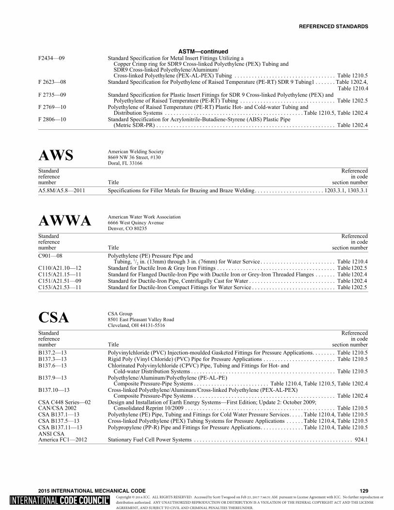
REFERENCED STANDARDS
2015 INTERNATIONAL MECHANICAL CODE 129
ASTM—continuedF2434—09 Standard Specification for Metal Insert Fittings Utilizing a
Copper Crimp ring for SDR9 Cross-linked Polyethylene (PEX) Tubing and SDR9 Cross-linked Polyethylene/Aluminum/Cross-linked Polyethylene (PEX-AL-PEX) Tubing . . . . . . . . . . . . . . . . . . . . . . . . . . . . . . . . . . . Table 1210.5
F 2623—08 Standard Specification for Polyethylene of Raised Temperature (PE-RT) SDR 9 Tubing1 . . . . . . . Table 1202.4,Table 1210.4
F 2735—09 Standard Specification for Plastic Insert Fittings for SDR 9 Cross-linked Polyethylene (PEX) and Polyethylene of Raised Temperature (PE-RT) Tubing . . . . . . . . . . . . . . . . . . . . . . . . . . . . . . . . . Table 1202.5
F 2769—10 Polyethylene of Raised Temperature (PE-RT) Plastic Hot- and Cold-water Tubing andDistribution Systems . . . . . . . . . . . . . . . . . . . . . . . . . . . . . . . . . . . . . . . . . . . . . . . . Table 1210.5, Table 1202.4
F 2806—10 Standard Specification for Acrylonitrile-Butadiene-Styrene (ABS) Plastic Pipe (Metric SDR-PR) . . . . . . . . . . . . . . . . . . . . . . . . . . . . . . . . . . . . . . . . . . . . . . . . . . . . . . . . . . . . . . Table 1202.4
AWS American Welding Society8669 NW 36 Street, #130Doral, FL 33166
Standard Referencedreference in codenumber Title section numberA5.8M/A5.8—2011 Specifications for Filler Metals for Brazing and Braze Welding. . . . . . . . . . . . . . . . . . . . . . . . 1203.3.1, 1303.3.1
AWWA American Water Work Association6666 West Quincy AvenueDenver, CO 80235
Standard Referencedreference in codenumber Title section numberC901—08 Polyethylene (PE) Pressure Pipe and
Tubing, 1/2 in. (13mm) through 3 in. (76mm) for Water Service . . . . . . . . . . . . . . . . . . . . . . . . . . Table 1210.4C110/A21.10—12 Standard for Ductile Iron & Gray Iron Fittings . . . . . . . . . . . . . . . . . . . . . . . . . . . . . . . . . . . . . . . . . Table 1202.5 C115/A21.15—11 Standard for Flanged Ductile-Iron Pipe with Ductile Iron or Grey-Iron Threaded Flanges . . . . . . . Table 1202.4 C151/A21.51—09 Standard for Ductile-Iron Pipe, Centrifugally Cast for Water . . . . . . . . . . . . . . . . . . . . . . . . . . . . . . Table 1202.4 C153/A21.53—11 Standard for Ductile-Iron Compact Fittings for Water Service . . . . . . . . . . . . . . . . . . . . . . . . . . . . . Table 1202.5
CSA CSA Group8501 East Pleasant Valley RoadCleveland, OH 44131-5516
Standard Referencedreference in codenumber Title section numberB137.2—13 Polyvinylchloride (PVC) Injection-moulded Gasketed Fittings for Pressure Applications. . . . . . . . Table 1210.5B137.3—13 Rigid Poly (Vinyl Chloride) (PVC) Pipe for Pressure Applications . . . . . . . . . . . . . . . . . . . . . . . . . Table 1210.5B137.6—13 Chlorinated Polyvinylchloride (CPVC) Pipe, Tubing and Fittings for Hot- and
Cold-water Distribution Systems . . . . . . . . . . . . . . . . . . . . . . . . . . . . . . . . . . . . . . . . . . . . . . . . . . Table 1210.5B137.9—13 Polyethylene/Aluminum/Polyethylene (PE-AL-PE)
Composite Pressure-Pipe Systems . . . . . . . . . . . . . . . . . . . . . . . . . . Table 1210.4, Table 1210.5, Table 1202.4B137.10—13 Cross-linked Polyethylene/Aluminum/Cross-linked Polyethylene (PEX-AL-PEX)
Composite Pressure-Pipe Systems . . . . . . . . . . . . . . . . . . . . . . . . . . . . . . . . . . . . . . . . . . . . . . . . . Table 1202.4CSA C448 Series—02 Design and Installation of Earth Energy Systems—First Edition; Update 2: October 2009;CAN/CSA 2002 Consolidated Reprint 10/2009 . . . . . . . . . . . . . . . . . . . . . . . . . . . . . . . . . . . . . . . . . . . . . . . . . . . . Table 1210.5CSA B137.1—13 Polyethylene (PE) Pipe, Tubing and Fittings for Cold Water Pressure Services. . . . . Table 1210.4, Table 1210.5CSA B137.5—13 Cross-linked Polyethylene (PEX) Tubing Systems for Pressure Applications . . . . . . Table 1210.4, Table 1210.5CSA B137.11—13 Polypropylene (PP-R) Pipe and Fittings for Pressure Applications. . . . . . . . . . . . . . . Table 1210.4, Table 1210.5ANSI CSA America FC1—2012 Stationary Fuel Cell Power Systems . . . . . . . . . . . . . . . . . . . . . . . . . . . . . . . . . . . . . . . . . . . . . . . . . . . . . . . 924.1
Copyright © 2014 ICC. ALL RIGHTS RESERVED. Accessed by Scott Twogood on Feb 23, 2017 7:46:51 AM pursuant to License Agreement with ICC. No further reproduction ordistribution authorized. ANY UNAUTHORIZED REPRODUCTION OR DISTRIBUTION IS A VIOLATION OF THE FEDERAL COPYRIGHT ACT AND THE LICENSEAGREEMENT, AND SUBJECT TO CIVIL AND CRIMINAL PENALTIES THEREUNDER.

REFERENCED STANDARDS
130 2015 INTERNATIONAL MECHANICAL CODE
DOL Department of LaborOccupational Safety and Health Administrationc/o Superintendent of DocumentsUS Government Printing OfficeWashington, DC 20402-9325
Standard Referencedreference in codenumber Title section number29 CFR Part 1910.1000 Air Contaminants . . . . . . . . . . . . . . . . . . . . . . . . . . . . . . . . . . . . . . . . . . . . . . . . . . . . . . . . . . . . . . . . . . . . . . 502.6(2009)29 CFR Part 1910.1025 Toxic and Hazardous Substances . . . . . . . . . . . . . . . . . . . . . . . . . . . . . . . . . . . . . . . . . . . . . . . . . . . . . . . . . 502.19(2009)
FS Federal Specifications*General Services Administration7th & D StreetsSpecification Section, Room 6039Washington, DC 20407
Standard Referencedreference in codenumber Title section numberWW-P-325B (1976) Pipe, Bends, Traps, Caps and Plugs; Lead (for Industrial Pressure and Soil and
Waste Applications) . . . . . . . . . . . . . . . . . . . . . . . . . . . . . . . . . . . . . . . . . . . . . . . . . . . . . . . . . . . . Table 1202.4*Standards are available from the Supt. of Documents, U.S. Government Printing Office, Washington, DC 20402-9325
ICC International Code Council, Inc.500 New Jersey Ave, NW6th FloorWashington, DC 20001
Standard Referencedreference in codenumber Title section numberIBC—15 International Building Code® . . . . . . . . . . . . . . . . . . . . . . . . . . . . . . . 201.3, 202, 301.15, 301.16, 301.17, 301.18,
302.1, 302.2, 304.8, 304.11, 308.4.2.2, 308.4.2.4,401.4, 401.5, 406.1, 501.3.1, 501.3.2, 501.10.2, 502.10,
502.10.1, 504.2, 504.10, 505.3, 506.3.3, 506.3.10, 506.3.12.2,506.4.1, 509.1, 510.6, 510.6.3, 510.6.2, 510.7, 510.7.1.1, 510.7.2,
510.7.3, 510.8, 511.1.5, 513.1, 513.2, 513.3, 513.4.3, 513.5, 513.5.2,513.5.2.1, 513.5.3, 513.5.3.2, 513.6.2, 513.10.5, 513.11.1, 513.12,
513.12.2, 513.20, 601.3, 602.2, 602.2.1.5.1, 602.2.1.5.2, 602.2.1.6.1, 602.2.1.6.2,602.3, 602.4, 603.1, 603.10, 603.13, 603.18.2, 604.5.4, 607.1.1, 607.1.2,
607.3.2.1, 607.5.1, 607.5.2, 607.5.3, 607.5.4, 607.5.4.1, 607.5.5,607.5.5.1, 607.5.6, 607.6, 607.6.1, 607.6.2, 607.6.2.1, 607.6.3,
701.2, 701.4.1, 701.4.2, 801.3, 801.16.1, 801.18.4, 801.18.4.1, 902.1, 908.3, 908.4,910.3, 924.1, 925.1, 926.1, 927.2, 928.1, 1004.6, 1105.1, 1206.4,
1210.8.2, 1305.2.1, 1402.4, 1402.4.1IECC—15 International Energy Conservation Code® . . . . . . . . . . . 301.2, 303.3, 312.1, 401.2, 514.1, 604.1, 1204.1, 1204.2IFC—15 International Fire Code® . . . . . . . . . . . . . . . . . . . . . . . . . . . . . . . . . . . . . . . . . . . 201.3, 310.1, 311.1, 502.4, 502.5,
502.7.2, 502.8.1, 502.9.1, 502.9.5, 502.9.5.2, 502.9.5.3,502.9.8.2, 502.9.8.3, 502.9.8.5, 502.9.8.6, 502.9.11, 502.10,
502.10.3, 502.16.2, 509.1, 510.2.1, 510.2.2, 510.5, 511.1.1, 513.1, 513.2,513.6.3, 513.12.1, 513.12.3, 513.12.4, 513.15, 513.16, 513.17, 513.18,513.19, 606.2.1, 606.4.1, 908.7, 924.1, 926.1, 1101.9, 1105.3, 1105.9,
1106.5, 1106.6, 1301.1, 1301.2, 1301.5IFGC—15 International Fuel Gas Code® . . . . . . . . . . . . . . . . 101.2, 201.3, 301.6, 701.1, 801.1, 901.1, 906.1, 926.1, 1101.5IPC—15 International Plumbing Code® . . . . . . . . . . . . . . . . . 201.3, 301.11, 307.2.2, 512.2, 908.5, 928.1, 1002.1, 1002.2,
1002.3, 1005.2, 1006.6, 1008.2, 1009.3, 1101.4,1201.1, 1206.2, 1206.3, 1210.8.1, 1401.2
IRC—15 International Residential Code® . . . . . . . . . . . . . . . . . . . . . . . . . . . . . . . . . . . . . . . . . . . . . . . . . . . . . . . . . . . 101.2
Copyright © 2014 ICC. ALL RIGHTS RESERVED. Accessed by Scott Twogood on Feb 23, 2017 7:46:51 AM pursuant to License Agreement with ICC. No further reproduction ordistribution authorized. ANY UNAUTHORIZED REPRODUCTION OR DISTRIBUTION IS A VIOLATION OF THE FEDERAL COPYRIGHT ACT AND THE LICENSEAGREEMENT, AND SUBJECT TO CIVIL AND CRIMINAL PENALTIES THEREUNDER.

REFERENCED STANDARDS
2015 INTERNATIONAL MECHANICAL CODE 131
IIAR International Institute of Ammonia Refrigeration1110 North Glebe RoadArlington, VA 22201
Standard Referencedreference in codenumber Title section number2—2014 Addendum A to Equipment, Design, and Installation of
Ammonia Mechanical Refrigerating Systems . . . . . . . . . . . . . . . . . . . . . . . . . . . . . . . . . . . . . 1101.6, 1105.6.3
MSS Manufacturers Standardization Society of the Valve & Fittings Industry, Inc.127 Park Street, N.E.Vienna, VA 22180
Standard Referencedreference in codenumber Title section numberSP 58—2009 Pipe Hangers and Supports—Materials Design and Manufacture, Selection,
Application and Installation . . . . . . . . . . . . . . . . . . . . . . . . . . . . . . . . . . . . . . . . . . . . . . . . . . . . . . . . . . . . 305.4
NAIMA North American Insulation Manufacturers Association44 Canal Center Plaza, Suite 310Alexandria, VA 22314
Standard Referencedreference in codenumber Title section numberAH116—09 Fibrous Glass Duct Construction Standards. . . . . . . . . . . . . . . . . . . . . . . . . . . . . . . . . . . . . . . . . . . . . 603.5, 603.9
NBBI National Board of Boiler and Pressure Vessel Inspectors1055 Crupper AvenueColumbus, OH 43229-1183
Standard Referencedreference in codenumber Title section numberNBIC—2011 National Board Inspection Code, Part 3 . . . . . . . . . . . . . . . . . . . . . . . . . . . . . . . . . . . . . . . . . . . . . . . . . . . . 1003.3
NFPA National Fire Protection Association1 Batterymarch ParkQuincy, MA 02169-7471
Standard Referencedreference in codenumber Title section number30A—15 Code for Motor Fuel-dispensing Facilities and Repair Garages . . . . . . . . . . . . . . . . . . . . . . . . . . . . . . . . . . 304.6 31—11 Standard for the Installation of Oil-burning Equipment . . . . . . . . . . . 701.1, 801.2.1, 801.18.1, 801.18.2, 920.2,
922.1, 1308.137—14 Standard for the Installation and Use of Stationary Combustion Engines and Gas Turbines . . . . . . . 915.1, 915.2 58—14 Liquefied Petroleum Gas Code . . . . . . . . . . . . . . . . . . . . . . . . . . . . . . . . . . . . . . . . . . . . . . . . . . . . . . . . . 502.9.10 69—14 Standard on Explosion Prevention Systems. . . . . . . . . . . . . . . . . . . . . . . . . . . . . . . . . . . . . . . . . . . . . . . . . 510.9.3 70—14 National Electrical Code . . . . . . . . . . . . . . . . . . . . . . . . . . . . . . . . . . . . 301.7, 306.3.1, 306.4.1, 511.1.1, 513.11,
513.12.2, 602.2.1.1, 927.2, 1104.2.2, 1106.3, 1106.472—13 National Fire Alarm and Signaling Code . . . . . . . . . . . . . . . . . . . . . . . . . . . . . . . . . . . . . . . . . . . . . . . . . . . . 606.3 82—14 Standard on Incinerators and Waste and Linen Handling Systems and Equipment . . . . . . . . . . . . . . . . . . . 601.1 85—15 Boiler and Combustion Systems Hazards Code. . . . . . . . . . . . . . . . . . . . . . . . . . . . . . . . . . . . . . . . . . . . . . 1004.191—15 Standard for Exhaust Systems for Air Conveying of Vapors, Gases, Mists, and
Noncombustible Particulate Solids . . . . . . . . . . . . . . . . . . . . . . . . . . . . . . . . . . . . . . . . . . . . 502.9.5.1, 502.17 92—15 Standard for Smoke Control Systems . . . . . . . . . . . . . . . . . . . . . . . . . . . . . . . . . . . . . . . . . . . . . . . 513.7, 513.8 96—14 Standard for Ventilation Control and Fire Protection of Commercial Cooking Operations . . . . . . . . . . . . . 507.1211—13 Standard for Chimneys, Fireplaces, Vents and Solid Fuel-burning Appliances . . . . . . . . . . . . . . . . . . . . . . 806.1 262—15 Standard Method of Test for Flame Travel and Smoke of Wires and Cables for
Use in Air-handling Spaces . . . . . . . . . . . . . . . . . . . . . . . . . . . . . . . . . . . . . . . . . . . . . . . . . . . . . . . . . 602.2.1.1
Copyright © 2014 ICC. ALL RIGHTS RESERVED. Accessed by Scott Twogood on Feb 23, 2017 7:46:51 AM pursuant to License Agreement with ICC. No further reproduction ordistribution authorized. ANY UNAUTHORIZED REPRODUCTION OR DISTRIBUTION IS A VIOLATION OF THE FEDERAL COPYRIGHT ACT AND THE LICENSEAGREEMENT, AND SUBJECT TO CIVIL AND CRIMINAL PENALTIES THEREUNDER.

REFERENCED STANDARDS
132 2015 INTERNATIONAL MECHANICAL CODE
NFPA—continued286—15 Standard Methods of Fire Tests for Evaluating Contribution of Wall and
Ceiling Interior Finish to Room Fire Growth . . . . . . . . . . . . . . . . . . . . . . . . . . . . . . . . . . . . . . . . . . . 602.2.1.6.2704—12 Standard System for Identification of the Hazards of Materials for
Emergency Response . . . . . . . . . . . . . . . . . . . . . . . . . . . . . . . . . . . . . . . . . . . . . . . 502.8.4, Table 1103.1, 510.1853—15 Standard on Installation of Stationary Fuel Power Plants . . . . . . . . . . . . . . . . . . . . . . . . . . . . . . . . . . . . . . . 924.1
NSF NSF International789 Dixboro Road, P. O. Box 130140Ann Arbor, MI 48113-0140
Standard Referencedreference in codenumber Title section numberNSF 358-1-2011 Polyethylene Pipe and Fittings for Water Based Ground Source
“Geothermal” Heat Pump Systems. . . . . . . . . . . . . . . . . . . . . . . . . . . . . . . . . . . . . .Table 1210.4, Table 1210.5
SMACNA Sheet Metal & Air-Conditioning Contractors National Assoc., Inc.4201 Lafayette Center DriveChantilly, VA 20151-1209
Standard Referencedreference in codenumber Title section numberSMACNA/ANSI—2015 HVAC Duct Construction Standards-Metal and
Flexible 4th Edition (ANSI). . . . . . . . . . . . . . . . . . . . . . . . . . . . . . . . . . . . . . . 603.4, Table 603.4, 603.9, 603.10SMACNA—10 Fibrous Glass Duct Construction Standards . . . . . . . . . . . . . . . . . . . . . . . . . . . . . . . . . . . . . . . . . . . . . 603.5, 603.9
UL UL LLC333 Pfingsten RoadNorthbrook, IL 60062-2096
Standard Referencedreference in codenumber Title section number17—2008 Vent or Chimney Connector Dampers for Oil-fired Appliances—
with revisions Through January 2010. . . . . . . . . . . . . . . . . . . . . . . . . . . . . . . . . . . . . . . . . . . . . . . . . . . . . 803.6 103—2010 Factory-built Chimneys, Residential Type and Building Heating Appliance—
with revisions through July 2012 . . . . . . . . . . . . . . . . . . . . . . . . . . . . . . . . . . . . . . . . . . . . . . . . . . . . . . . . 805.2 127—2011 Factory-built Fireplaces . . . . . . . . . . . . . . . . . . . . . . . . . . . . . . . . . . . . . . . . . . . . . . . . . . . . . . 903.1, 903.3, 903.4174—04 Household Electric Storage Tank Water Heaters—with revisions through September 2012 . . . . . . . . . . . 1002.1 180—2012 Liquid-level Indicating Gauges for Oil Burner Fuels and Other Combustible Liquids . . . . . . . . . . . . . . . . 1306.4181—05 Factory-made Air Ducts and Air Connectors—
with revisions through October 2008 . . . . . . . . . . . . . . . . . . . . . . . . . . . . . . . . . . . . . . . . 512.2, 603.5, 603.6.1,603.6.2, 603.9, 604.13
181A—2013 Closure Systems for Use with Rigid Air Ducts and Air Connectors . . . . . . . . . . . . . . . . . . . . . . . . . . . . . . . 603.9181B—2013 Closure Systems for Use with Flexible Air Ducts and Air Connectors . . . . . . . . . . . . . . . . . . . . . . . . . . . . . 603.9 197—10 Commercial Electric Cooking Appliances—with revisions through June 2011 . . . . . . . . . . . . . . . . . . . . . . 917.1207—2009 Refrigerant-containing Components and Accessories, Nonelectrical . . . . . . . . . . . . . . . . . . . . . . . . . . . . . 1101.2 263—2011 Standard for Fire Test of Building Construction and Materials . . . . . . . . . . . 607.5.2, 607.5.5, 607.6.1, 607.6.2.1268—2009 Smoke Detectors for Fire Alarm Systems . . . . . . . . . . . . . . . . . . . . . . . . . . . . . . . . . . . . . . . . . . . . . . . . . . . 606.1 268A—2008 Smoke Detectors for Duct Application—with revisions through September 2009 . . . . . . . . . . . . . . . . . . . . 606.1 343—2008 Pumps for Oil-Burning Appliances—with revisions through June 2013. . . . . . . . . . . . . . . . . . . . . . . . . . . 1302.7 378—06 Draft Equipment—with revisions through January 2010 . . . . . . . . . . . . . . . . . . . . . . . . . . . . . . . . . 804.3, 804.3.8391—2010 Solid-fuel and Combination-fuel Central and Supplementary Furnaces—
with revisions through March 2010 . . . . . . . . . . . . . . . . . . . . . . . . . . . . . . . . . . . . . . . . . . . . . . . . . . . . . . 918.1 412—2011 Refrigeration Unit Coolers—with revisions through August 2012 . . . . . . . . . . . . . . . . . . . . . . . . . . . . . . . 1101.2 471—2010 Commercial Refrigerators and Freezers—with revisions through December 2012. . . . . . . . . . . . . . . . . . . 1101.2 499—05 Electric Heating Appliances—with revisions through February 2013. . . . . . . . . . . . . . . . . . . . . . . . . 912.1, 923.1508—99 Industrial Control Equipment—with revisions through March 2013. . . . . . . . . . . . . . . . . . . . . . . . . . . . . . 307.2.3 536—97 Flexible Metallic Hose—with revisions through June 2003 . . . . . . . . . . . . . . . . . . . . . . . . . . . . . . . . . . . . 1302.8
Copyright © 2014 ICC. ALL RIGHTS RESERVED. Accessed by Scott Twogood on Feb 23, 2017 7:46:51 AM pursuant to License Agreement with ICC. No further reproduction ordistribution authorized. ANY UNAUTHORIZED REPRODUCTION OR DISTRIBUTION IS A VIOLATION OF THE FEDERAL COPYRIGHT ACT AND THE LICENSEAGREEMENT, AND SUBJECT TO CIVIL AND CRIMINAL PENALTIES THEREUNDER.

REFERENCED STANDARDS
2015 INTERNATIONAL MECHANICAL CODE 133
UL—continued555—06 Fire Dampers—with revisions through May 2012. . . . . . . . . . . . . . . . . . . . . . . . . . . . . . . . . . . . . . . . . . . . 607.3.1 555C—06 Ceiling Dampers—with revisions through May 2010 . . . . . . . . . . . . . . . . . . . . . . . . . . . . . . . . . . . . . . . . . 607.3.1 555S—99 Smoke Dampers—with revisions through May 2012 . . . . . . . . . . . . . . . . . . . . . . . . . . . . . . . . . . . . . . . . . 607.3.1 586—2009 High-Efficiency, Particulate, Air Filter Units . . . . . . . . . . . . . . . . . . . . . . . . . . . . . . . . . . . . . . . . . . . . . . . . 605.2 641—2010 Type L Low-temperature Venting Systems—with revisions through May 2013 . . . . . . . . . . . . . . . . . . . . . 802.1 705—2004 Standard for Power Ventilators—with revisions through March 2012 . . . . . . . . . . . . . . . . . . . . . . . . . . . . . 504.5710—2012 Exhaust Hoods for Commercial Cooking Equipment . . . . . . . . . . . . . . . . . . . . . . . . . . . . . . . . . . . . . . . . . . 507.1 710B—2011 Recirculating Systems . . . . . . . . . . . . . . . . . . . . . . . . . . . . . . . . . . . . . . . . . . . . . . . . . . . . . . . . . . . 507.1, 507.2 723—2008 Standard for Test for Surface Burning Characteristics of Building Materials . . . . . . . . . . . 510.9, 602.2, 602.2.1,
602.2.1.6, 602.2.1.6.2, 602.2.1.6.3, 602.2.1.7, 604.3, 1204.1726—95 Oil-fired Boiler Assemblies—with revisions through April 2011 . . . . . . . . . . . . . . . . . . . . . . . . . . . 916.1, 1004.1 727—06 Oil-fired Central Furnace—with revisions through April 2010 . . . . . . . . . . . . . . . . . . . . . . . . . . . . . . . . . . 918.1 729—03 Oil-fired Floor Furnaces—with revisions through August 2012 . . . . . . . . . . . . . . . . . . . . . . . . . . . . . . . . . . 910.1 730—03 Oil-fired Wall Furnaces—with revisions through August 2012 . . . . . . . . . . . . . . . . . . . . . . . . . . . . . . . . . . 909.1 731—95 Oil-fired Unit Heaters—with revisions through August 2012 . . . . . . . . . . . . . . . . . . . . . . . . . . . . . . . . . . . . 920.1 732—95 Oil-fired Storage Tank Water Heaters—with revisions through April 2010 . . . . . . . . . . . . . . . . . . . . . . . . 1002.1 737—2011 Fireplace Stoves . . . . . . . . . . . . . . . . . . . . . . . . . . . . . . . . . . . . . . . . . . . . . . . . . . . . . . . . . . . . . . . . . . . . . . . 905.1 762—2010 Outline of Investigation for Power Ventilators for Restaurant Exhaust Appliances . . . . . . . . . . . . . . . . . . 506.5.1 791—06 Residential Incinerators—with revisions through April 2010 . . . . . . . . . . . . . . . . . . . . . . . . . . . . . . . . . . . . 907.1 834—04 Heating, Water Supply and Power Boilers Electric—with revisions through January 2013. . . . . . . . . . . . 1004.1 842—07 Valves for Flammable Fluids—with revisions through October 2012 . . . . . . . . . . . . . . . . . . . . . . . . . . . . 1307.1858—05 Household Electric Ranges—with revisions through April 2012 . . . . . . . . . . . . . . . . . . . . . . . . . . . . . . . . . 917.1 867—2011 Electrostatic Air Cleaners—with revisions through February 2013 . . . . . . . . . . . . . . . . . . . . . . . . . . . . . . . 605.2 875—09 Electric Dry Bath Heater—with revisions through November 2011 . . . . . . . . . . . . . . . . . . . . . . . . . . . . . . . 914.2 896—93 Oil-burning Stoves—with revisions through August 2012 . . . . . . . . . . . . . . . . . . . . . . . . . . . . . . . . . 917.1, 922.1 900—04 Air Filter Units—with revisions through February 2012. . . . . . . . . . . . . . . . . . . . . . . . . . . . . . . . . . . . . . . . 605.2907—94 Fireplace Accessories—with revisions through April 2010. . . . . . . . . . . . . . . . . . . . . . . . . . . . . . . . . . . . . . 902.2923—2013 Microwave Cooking Appliances . . . . . . . . . . . . . . . . . . . . . . . . . . . . . . . . . . . . . . . . . . . . . . . . . . . . . . . . . . 917.1959—2010 Medium Heat Appliance Factory-built Chimneys . . . . . . . . . . . . . . . . . . . . . . . . . . . . . . . . . . . . . . . . . . . . . 805.5 1046—2010 Grease Filters for Exhaust Ducts—with revisions through January 2012 . . . . . . . . . . . . . . . . . . . . . . . . . . 507.2.81240—2012 Electric Commercial Clothes—Drying Equipment—with revisions through October 2012. . . . . . . . . . . . . 913.11261—01 Electric Water Heaters for Pools and Tubs—with revisions through July 2012 . . . . . . . . . . . . . . . . . . . . . . 916.11453—04 Electric Booster and Commercial Storage Tank Water Heaters—
with revisions through July 2011 . . . . . . . . . . . . . . . . . . . . . . . . . . . . . . . . . . . . . . . . . . . . . . . . . . . . . . . 1002.11479—03 Fire Tests of Through-penetration Firestops—
with revisions through October 2012 . . . . . . . . . . . . . . . . . . . . . . . . . . . . . . . . . . . . . . . . 506.3.11.2, 506.3.11.31482—2011 Solid-fuel Type Room Heaters. . . . . . . . . . . . . . . . . . . . . . . . . . . . . . . . . . . . . . . . . . . . . . . . . . . . . . . . . . . . 905.11618—09 Wall Protectors, Floor Protectors and Hearth Extensions—
with revisions through May 2013. . . . . . . . . . . . . . . . . . . . . . . . . . . . . . . . . . . . . . . . . . . . 308.4.1, 903.2, 905.31777—2007 Chimney Liners—with revisions through July 2009 . . . . . . . . . . . . . . . . . . . . . . . . . . . . . . . . . 801.16.1, 801.18.41812—2013 Standard for Ducted Heat Recovery Ventilators . . . . . . . . . . . . . . . . . . . . . . . . . . . . . . . . . . . . . . . . . . . . . . 514.11815—2012 Standard for Nonducted Heat Recovery. . . . . . . . . . . . . . . . . . . . . . . . . . . . . . . . . . . . . . . . . . . . . . . . . . . . . 514.11820—04 Fire Test of Pneumatic Tubing for Flame and Smoke Characteristics—
with revisions through May 2013. . . . . . . . . . . . . . . . . . . . . . . . . . . . . . . . . . . . . . . . . . . . . . . . . . . . . 602.2.1.3 1887—04 Fire Tests of Plastic Sprinkler Pipe for Visible Flame and Smoke Characteristics—
with revisions through May 2013. . . . . . . . . . . . . . . . . . . . . . . . . . . . . . . . . . . . . . . . . . . . . . . . . . . . . 602.2.1.21978—2010 Grease Ducts. . . . . . . . . . . . . . . . . . . . . . . . . . . . . . . . . . . . . . . . . . . . . . . . . . . . . . . . . . . . . . . . . . 506.3.2, 506.3.61995—2011 Heating and Cooling Equipment . . . . . . . . . . . . . . . . . . . . . . . . . . . . . . . . . . . 908.1, 911.1, 918.1, 918.2, 1101.21996—2009 Electric Duct Heaters—with revisions through November 2011. . . . . . . . . . . . . . . . . . . . . . . . . . . . . . . . . . 911.12024—2011 Standard for Safety Optical-Fiber and Communications Cable Raceway—
with revisions through April 2011 . . . . . . . . . . . . . . . . . . . . . . . . . . . . . . . . . . . . . . . . . . . . . . . . . . . . 602.2.1.12043—2008 Fire Test for Heat and Visible Smoke Release for Discrete Products and their
Accessories Installed in Air-handling Spaces . . . . . . . . . . . . . . . . . . . . . . . . . . . . . . . . . . . . . . . . . . 602.2.1.4.2 2158—97 Electric Clothes Dryers—with revisions through March 2009 . . . . . . . . . . . . . . . . . . . . . . . . . . . . . . . . . . . 913.12158A—2010 Outline of Investigation for Clothes Dryer Transition Duct . . . . . . . . . . . . . . . . . . . . . . . . . . . . . . . . . . . . 504.8.32162—01 Outline of Investigation for Commercial Wood-fired Baking Ovens-Refractory Type . . . . . . . . . . . . . . . . 917.12200—2012 Stationery Engine Generator Assemblies—with revisions through June 2013 . . . . . . . . . . . . . . . . . . . . . . . 915.12221—2010 Tests of Fire Resistive Grease Duct Enclosure Assemblies. . . . . . . . . . . . . . . . . . . . . . . . . . . . . . . . . . 506.3.11.32518—05 Air Dispersion System Materials . . . . . . . . . . . . . . . . . . . . . . . . . . . . . . . . . . . . . . . . . . . . . . . . . . . . . . . . . 603.172523—09 Solid Fuel-fired Hydronic Heating Appliances—with revisions through February 2013 . . . . . . . . 1002.1, 1004.1
Copyright © 2014 ICC. ALL RIGHTS RESERVED. Accessed by Scott Twogood on Feb 23, 2017 7:46:51 AM pursuant to License Agreement with ICC. No further reproduction ordistribution authorized. ANY UNAUTHORIZED REPRODUCTION OR DISTRIBUTION IS A VIOLATION OF THE FEDERAL COPYRIGHT ACT AND THE LICENSEAGREEMENT, AND SUBJECT TO CIVIL AND CRIMINAL PENALTIES THEREUNDER.

134 2015 INTERNATIONAL MECHANICAL CODECopyright © 2014 ICC. ALL RIGHTS RESERVED. Accessed by Scott Twogood on Feb 23, 2017 7:46:51 AM pursuant to License Agreement with ICC. No further reproduction ordistribution authorized. ANY UNAUTHORIZED REPRODUCTION OR DISTRIBUTION IS A VIOLATION OF THE FEDERAL COPYRIGHT ACT AND THE LICENSEAGREEMENT, AND SUBJECT TO CIVIL AND CRIMINAL PENALTIES THEREUNDER.

2015 INTERNATIONAL MECHANICAL CODE 135
Appendix AChimney Connector Pass-Throughs
(This appendix is informative and is not part of the code.)
For SI: 1 inch = 25.4 mm.
FIGURE A-1CHIMNEY CONNECTOR SYSTEMS
(continued)
Copyright © 2014 ICC. ALL RIGHTS RESERVED. Accessed by Scott Twogood on Feb 23, 2017 7:46:51 AM pursuant to License Agreement with ICC. No further reproduction ordistribution authorized. ANY UNAUTHORIZED REPRODUCTION OR DISTRIBUTION IS A VIOLATION OF THE FEDERAL COPYRIGHT ACT AND THE LICENSEAGREEMENT, AND SUBJECT TO CIVIL AND CRIMINAL PENALTIES THEREUNDER.

APPENDIX A
136 2015 INTERNATIONAL MECHANICAL CODE
For SI: 1 inch = 25.4 mm.
FIGURE A-1—continuedCHIMNEY CONNECTOR SYSTEMS
Copyright © 2014 ICC. ALL RIGHTS RESERVED. Accessed by Scott Twogood on Feb 23, 2017 7:46:51 AM pursuant to License Agreement with ICC. No further reproduction ordistribution authorized. ANY UNAUTHORIZED REPRODUCTION OR DISTRIBUTION IS A VIOLATION OF THE FEDERAL COPYRIGHT ACT AND THE LICENSEAGREEMENT, AND SUBJECT TO CIVIL AND CRIMINAL PENALTIES THEREUNDER.

2015 INTERNATIONAL MECHANICAL CODE 137
Appendix BRecommended Permit Fee Schedule
(This appendix is informative and is not part of the code.)
B101MECHANICAL WORK, OTHER THAN GAS PIPING SYSTEMS
B101.1 Initial FeeFor issuing each permit $___
B101.2 Additional FeesB101.2.1 Fee for inspecting heating, ventilating, ductwork, air-conditioning, exhaust, venting, combustion air, pressure ves-sel, solar, fuel oil and refrigeration systems and appliance installations shall be $___ for the first $1,000.00, or fractionthereof, of valuation of the installation plus $___ for each additional $1,000.00 or fraction thereof.B101.2.2 Fee for inspecting repairs, alterations and additions to an existing system shall be $___ plus $___ for each$1,000.00 or fraction thereof.B101.2.3 Fee for inspecting boilers (based upon Btu input):
For SI:1 British thermal unit = 0.2931 W, 1 bhp = 33,475 Btu/hr
B102FEE FOR REINSPECTION
If it becomes necessary to make a reinspection of a heating, ventilation, air-conditioning or refrigeration system, or boiler instal-lation, the installer of such equipment shall pay a reinspection fee of $___.
B103TEMPORARY OPERATION INSPECTION FEE
When preliminary inspection is requested for purposes of permitting temporary operation of a heating, ventilating, refrigeration,or air-conditioning system, or portion thereof, a fee of $___ shall be paid by the contractor requesting such preliminary inspec-tion. If the system is not approved for temporary operation on the first preliminary inspection, the usual reinspection fee shall becharged for each subsequent preliminary inspection for such purpose.
B104SELF-CONTAINED UNITS LESS THAN 2 TONS
In all buildings, except one- and two-family dwellings, where self-contained air-conditioning units of less than 2 tons (7.034 kW)are to be installed, the fee charged shall be that for the total cost of all units combined (see B101.2.1 for rate).
33,000 Btu (1 bhp) to 165,000 (5 bhp) $ ___
165,001 Btu (5 bhp) to 330,000 (10 bhp) $ ___
330,001 Btu (10 bhp) to 1,165,000 (52 bhp) $ ___
1,165,001 Btu (52 bhp) to 3,300,000 (98 bhp) $ ___
Over 3,300,000 Btu (98 bhp) $ ___
Copyright © 2014 ICC. ALL RIGHTS RESERVED. Accessed by Scott Twogood on Feb 23, 2017 7:46:51 AM pursuant to License Agreement with ICC. No further reproduction ordistribution authorized. ANY UNAUTHORIZED REPRODUCTION OR DISTRIBUTION IS A VIOLATION OF THE FEDERAL COPYRIGHT ACT AND THE LICENSEAGREEMENT, AND SUBJECT TO CIVIL AND CRIMINAL PENALTIES THEREUNDER.

138 2015 INTERNATIONAL MECHANICAL CODE
Copyright © 2014 ICC. ALL RIGHTS RESERVED. Accessed by Scott Twogood on Feb 23, 2017 7:46:51 AM pursuant to License Agreement with ICC. No further reproduction ordistribution authorized. ANY UNAUTHORIZED REPRODUCTION OR DISTRIBUTION IS A VIOLATION OF THE FEDERAL COPYRIGHT ACT AND THE LICENSEAGREEMENT, AND SUBJECT TO CIVIL AND CRIMINAL PENALTIES THEREUNDER.

2015 INTERNATIONAL MECHANICAL CODE 139
INDEX
AADMINISTRATION AND
ENFORCEMENT . . . . . . . . . . . . . . . . . . . . Chapter 1AIR
Combustion . . . . . . . . . . . . . . . . . . . . . . . . Chapter 7Dispersion systems . . . . . . . . . . . . . . . . . . . . 603.17Distribution systems . . . . . . . . . . . . . . . . . . Chapter 6Filters . . . . . . . . . . . . . . . . . . . . . . . . . . . . . . . . . . 605Recirculation. . . . . . . . . . . . . . . . . . . . . . . . . . 403.2.1Supply. . . . . . . . . . . . . . . . . . . . . . . . . . . . . Chapter 4Transfer . . . . . . . . . . . . . . . . . . . . . . . . . . . . . 403.2.2Ventilation. . . . . . . . . . . . . . . . . . . . . . . . . . Chapter 4
ALTERNATIVE MATERIALS AND METHODS . . . . . . . . . . . . . . . . . . . . . . . . . . . . 105.2
AMMONIA . . . . . . . . . . . . . . . . 1105.8, 1106.3, 1106.4APPEAL . . . . . . . . . . . . . . . . . . . . . . . . . . . . . . . . . 109APPLIANCES
Access . . . . . . . . . . . . . . . . . . . . . . . . . . . . . . . . . 306Cooking . . . . . . . . . . . . . . . . . . . . . . . . . . . . . . . . 917Hazardous location . . . . . . . . . . . . . . . . . . . . . . 303.2Installation . . . . . . . . . . . . . . . . . . . . . . Chapters 3, 9Outdoors. . . . . . . . . . . . . . . . . . . . . . . . . . . . . . 303.6Prohibited locations . . . . . . . . . . . . . . . . . . . . . 303.3
APPLICABILITY OF CODE . . . . . . . . . . . . . . . . . . 102APPROVAL . . . . . . . . . . . . . . . . . . . . . . . . . . . . . . . 105ATTIC VENTILATION . . . . . . . . . . . . . . . . . . . . . . . 406AUTOMATIC FIRE SUPPRESSION,
KITCHEN EXHAUST . . . . . . . . . . . . . . . . . . . . . . 509AUTOMATIC VENT DAMPERS . . . . . . . . . . . . . 803.6
BBALANCING, VENTILATION SYSTEM . . . . . . . 403.7BARBECUE APPLIANCES . . . . . . . . . . . . . . . . . . 906BATHROOM VENTILATION. . . . . . . . . . . . . . 402, 403BLOWOFF VALVE, STEAM . . . . . . . . . . . . . . . . . 1008BOILERS
Approval . . . . . . . . . . . . . . . . . . . . . . . . . . . . . 1004.1Controls . . . . . . . . . . . . . . . . . . . . . . . . . . . . . . . 1006Gauges . . . . . . . . . . . . . . . . . . . . . . . . . . . . . . . . 1010General . . . . . . . . . . . . . . . . . . . . . . . . . . . . . . . . 1001Low-water cutoff . . . . . . . . . . . . . . . . . . . . . . . . . 1007Rooms . . . . . . . . . . . . . . . . . . . . . . . . . 304.7, 1004.6Tests. . . . . . . . . . . . . . . . . . . . . . . . . . . . . . . . . . 1011
BURNER, CONVERSION . . . . . . . . . . . . . . . . . . . . 919
CCANOPY HOODS . . . . . . . . . . . . . . . . . 507.12, 507.13CEILING DAMPERS . . . . . . . . . . . . . . . . . . . . . . . . 607CHILLED WATER PIPING . . . . . . . . . . . . . Chapter 12CHIMNEYS AND VENTS
Connectors . . . . . . . . . . . . . . . . . . . . . . . . . . . . . . 803Dampers . . . . . . . . . . . . . . . . . . . . . . . . . 803.5, 803.6Direct vents . . . . . . . . . . . . . . . . . . . . . . . . . . . . 804.1Exhausters . . . . . . . . . . . . . . . . . . . . . . . . . . . . 804.3Existing . . . . . . . . . . . . . . . . . . . . . . . . . . . . . . 801.18Factory built . . . . . . . . . . . . . . . . . . . . . . . . . 802, 805General . . . . . . . . . . . . . . . . . . . . . . . . . . . . . . . . . 801Liners . . . . . . . . . . . . . . . . . . 801.16, 801.17, 801.18Masonry, general . . . . . . . . . . . . . . . . . . . . . . . . . 801Offsets. . . . . . . . . . . . . . . . . . . . . . . . . . . . . . . . 805.3Vents. . . . . . . . . . . . . . . . . . . . . . . . . . . . . . . . . . . 802
CLEANOUTSClothes dryer exhaust . . . . . . . . . . . . . . . . . . . . 504.3Kitchen exhaust . . . . . . . . 506.3.8, 506.3.9, 506.3.12Masonry chimneys . . . . . . . . . . . . . . . . . . . . . 801.13
CLEARANCESAppliance in garages . . . . . . . . . 304.3, 304.6, 304.7Chimney and vent . . . . . . . . . . . . . . . . . . . . . 801.18.4Connectors . . . . . . . . . . . . . . . . . . . . . . . . . . 803.10.6Kitchen exhaust . . . . . . . . . . . . . . . . . 506.3.6, 507.9Reduction . . . . . . . . . . . . . . . . . . . . . . . . . . . . . . . 308Specific appliances . . . . . . . . . . . . . . . . . . . Chapter 9
CLOTHES DRYERAppliance . . . . . . . . . . . . . . . . . . . . . . . . . . . . . . . 913Exhaust . . . . . . . . . . . . . . . . . . . . . . . . . . . . . . . . . 504
COAL-BURNING APPLIANCES. . . . . . . . . . Chapter 9CODE OFFICIAL . . . . . . . . . . . . . . . . . . . 103, 104, 202COLLECTORS, SOLAR . . . . . . . . . . . . 1402.4, 1404.1COMBUSTIBLE LIQUID STORAGE TANK . . . . . 1301COMBUSTIBLES, REDUCED CLEARANCE . . . . . 308COMBUSTION AIR . . . . . . . . . . . . . . . . . . . . Chapter 7COMMERCIAL KITCHEN EXHAUST . . . . . . . . . . . 506
Hoods . . . . . . . . . . . . . . . . . . . . . . . . . . . . . . . . . . 507CONDENSATE DISPOSAL. . . . . . . . . . . . . . . . . . . 307CONDENSATION
Ducts. . . . . . . . . . . . . . . . . . . . . . . . . . . . . . . . 603.12Piping . . . . . . . . . . . . . . . . . . . . . . . . . . . . . . . 1107.4
CONFLICTS. . . . . . . . . . . . . . . . . . . . . 102.8.1, 102.8.2CONNECTORS, CHIMNEY OR VENT . . . . . . . . . . 803CONTAMINANTS,
VENTILATION AIR. . . . . . . . . . . . . . . . . 401.4, 401.6
Copyright © 2014 ICC. ALL RIGHTS RESERVED. Accessed by Scott Twogood on Feb 23, 2017 7:46:51 AM pursuant to License Agreement with ICC. No further reproduction ordistribution authorized. ANY UNAUTHORIZED REPRODUCTION OR DISTRIBUTION IS A VIOLATION OF THE FEDERAL COPYRIGHT ACT AND THE LICENSEAGREEMENT, AND SUBJECT TO CIVIL AND CRIMINAL PENALTIES THEREUNDER.

INDEX
140 2015 INTERNATIONAL MECHANICAL CODE
CONVERSION BURNERS . . . . . . . . . . . . . . . . . . . 919CONVEYOR SYSTEMS . . . . . . . . . . . . . . . . . . . . . 511COOKING APPLIANCES. . . . . . . . . . . . . . . . . . . . 917COOLING TOWERS. . . . . . . . . . . . . . . . . . . . . . . . 908COOLING WATER PIPING . . . . . . . . . . . . Chapter 12COVERING, DUCT . . . . . . . . . . . . . . . . . . . . . . . . 604.3CRAWL SPACE PLENUMS. . . . . . . . . . . . . . . . . . 602CRAWL SPACE, VENTILATION . . . . . . . . . . . . . . 406CREMATORIES . . . . . . . . . . . . . . . . . . . . . . . . . . . 907CUTTING, NOTCHING, BORING. . . . . . . . . . . . . . 302
D
DAMPERSChimney or vent. . . . . . . . . . . . . . . . . . . 803.5, 803.6Fire. . . . . . . . . . . . . . . . . . . . . . . . . . . . . . . . . . . . 607Smoke . . . . . . . . . . . . . . . . . . . . . . . . . . . . . . . . . 607
DEFINITIONS . . . . . . . . . . . . . . . . . . . . . . . . Chapter 2DETECTORS, DUCT SMOKE . . . . . . . . . . . . . . . . 606DOCUMENTS . . . . . . . . . . . . . . . . . . . . . . . . . . 106.3.1DRYER, CLOTHES
Exhaust . . . . . . . . . . . . . . . . . . . . . . . . . . . . . . . . 504General . . . . . . . . . . . . . . . . . . . . . . . . . . . . . . . . 913
DUCTClothes dryer exhaust . . . . . . . . . . . . . . . . . . . . . 504Construction. . . . . . . . . . . . . . . . . . . . . . . . . . . . . 603Covering . . . . . . . . . . . . . . . . . . . . . . . . . . . . . . 604.3Detectors, smoke. . . . . . . . . . . . . . . . . . . . . . . . . 606Diffusers. . . . . . . . . . . . . . . . . . . . . . . . . . . . . . 603.18Enclosure. . . . . . . . . . . . . . . . . . . . . . 506.3.11, 510.4Exhaust . . . . . . . . . . . . . . . . . . . . . . . . . . . . . . . 501.5Fire damper . . . . . . . . . . . . . . . . . . . . . . . . . . . . . 607Flexible . . . . . . . . . . . . . . . . . . . . . . . . . . . . . . . 603.6Furnace . . . . . . . . . . . . . . . . . . . . . . . . . . . . . . . 918.2Hangers and supports . . . . . . . . . . . . . . . . . . . 603.10Hazardous exhaust . . . . . . . . . . . . . . . . . . . . . . . 510Installation . . . . . . . . . . . . . . . . . . . . . . . . . . . . . . 603Insulation . . . . . . . . . . . . . . . . . . . . . . . . . . . . . . . 604Joints, seams and connections . . . . . . . . . . . . . 603.9Kitchen exhaust . . . . . . . . . . . . . . . . . . . . . . . . . . 506Lining . . . . . . . . . . . . . . . . . . . . . . . . . . . . . . . . . 604.3Penetrations. . . . . . . . . . . . . . . . . . . . . . . . . . . . . 607Plastic . . . . . . . . . . . . . . . . . . . . . . . . . . . . . . 603.8.3Private garage . . . . . . . . . . . . . . . . . . . . . . . . . . 603.7Sizing . . . . . . . . . . . . . . . . . . . . . . . . . . . . . . . . . 603.2Smoke damper . . . . . . . . . . . . . . . . . . . . . . . . . . 607Systems . . . . . . . . . . . . . . . . . . . . . . . . . . . Chapter 6Underground . . . . . . . . . . . . . . . . . . . . . . . . . . . 603.8Underground grease . . . . . . . . . . . . . . . . . . 506.3.10
DUST, STOCK AND REFUSECONVEYOR SYSTEMS . . . . . . . . . . . . . . . . . . . 511
EELECTRIC INSTALLATION . . . . . . . . . . . . . . . .301.10ENERGY EFFICIENCY. . . . . . . . . . . . . . . . . . . . .301.2ENERGY RECOVERY SYSTEMS . . . . . . . . . . . . . 514ENGINE/TURBINE EQUIPMENT . . . . . . . . . . . . . . 915EQUIPMENT ACCESS . . . . . . . . . . . . . . . . . . . . . . 306EQUIPMENT IDENTIFICATION . . . . . .304.12, 504.6.5EVAPORATIVE COOLING . . . . . . . . . . . . . . . . . . . 928EXHAUST, DOMESTIC . . . . . . . . . . . . . . . . . . . . . 505EXHAUST, DOWNDRAFT . . . . . . . . . . . . . . . . . .507.2EXHAUST, REQUIRED SYSTEMS . . . . . . . . . . . . 502
Clothes dryer . . . . . . . . . . . . . . . . . . . . . . . . . . . . 504Discharge. . . . . . . . . . . . . . . . . . . . . . . . . . . . . .501.3Ducts . . . . . . . . . . . . . . . . . . . . . . . . . . . . . . . . .501.4Independence . . . . . . . . . . . . . . . . . . . . . . . . . .501.2Outlets . . . . . . . . . . . . . . . . . . . . . . . . .501.3, 501.3.1Kitchen . . . . . . . . . . . . . . . . . . . . . . . . . . . . . 506, 507Machinery room . . . . . . . . . . . . . . . . . . . . 1105, 1106Mechanical . . . . . . . . . . . . . . . . . . . . . 403, Chapter 5Ventilator openings . . . . . . . . . . . . . . . . 401.4, 401.5System, hazardous . . . . . . . . . . . . . . . . . . . . . . . 510
EXHAUSTER, MECHANICAL FLUE . . . . . . . . . . . 804EXISTING SYSTEMS . . . . . . . . . . . . . . . . . . . . . .102.2EXPLOSION VENTING . . . . . . . . . . . . . . . . . . . . . 310
FFACTORY BUILT
Barbecue appliance . . . . . . . . . . . . . . . . . . . . . . . 906Chimneys . . . . . . . . . . . . . . . . . . . . . . . . . . . . . . . 805Commercial exhaust hoods . . . . . . . . . . . . . . . .507.1Ducts (kitchen exhaust) . . . . . . . . 506.3.1.1, 506.3.2,
506.3.2.5, 506.3.6, 506.3.11.3Fireplaces. . . . . . . . . . . . . . . . . . . . . . . . . . . . . . . 903
FANS, EXHAUST . . . . . . . . . . . . . . . . . . . 503, 506.5.1FILTERS, AIR . . . . . . . . . . . . . . . . . . . . . . . . . . . . . 605FILTERS, GREASE . . . . . . . . . . . . . . . . . . . . . .507.11FIRE DAMPERS . . . . . . . . . . . . . . . . . . . . . . . . . . . 607FIRE SUPPRESSION
Hazardous exhaust . . . . . . . . . . . . . . . . . . . . . .510.7Kitchen exhaust . . . . . . . . . . . . . . . . . . . . . . . . . . 509
FIREPLACESAccessories . . . . . . . . . . . . . . . . . . . . . . . . . . . .901.4Factory built . . . . . . . . . . . . . . . . . . . . . . . . . . . . . 903Masonry . . . . . . . . . . . . . . . . . . . . . . . . . . . . . . .902.1
FIREPLACE STOVE. . . . . . . . . . . . . . . . . . . . . . . . 905FLEXIBLE CONNECTORS (DUCT) . . . . . 603.6, 607.7FLEXIBLE CONNECTORS, HYDRONIC . . . . . .1202.7FLEXIBLE DUCTS . . . . . . . . . . . . . . . . . . 603.6, 607.7FLOOD HAZARD . . . . . . . . . . .301.16, 401.4, 501.3.2,
602.4, 603.13
Copyright © 2014 ICC. ALL RIGHTS RESERVED. Accessed by Scott Twogood on Feb 23, 2017 7:46:51 AM pursuant to License Agreement with ICC. No further reproduction ordistribution authorized. ANY UNAUTHORIZED REPRODUCTION OR DISTRIBUTION IS A VIOLATION OF THE FEDERAL COPYRIGHT ACT AND THE LICENSEAGREEMENT, AND SUBJECT TO CIVIL AND CRIMINAL PENALTIES THEREUNDER.

INDEX
2015 INTERNATIONAL MECHANICAL CODE 141
FLOOR FURNACE . . . . . . . . . . . . . . . . . . . . . . . . . 910FLUE LINERS . . . . . . . . . . . . . . . . . . 801.16, 801.18.2FUEL CELLS. . . . . . . . . . . . . . . . . . . . . . . . . . . . . . 924FUEL, CONVERSION . . . . . . . . . . . . . . . . . . . . 301.12FUEL OIL
Piping . . . . . . . . . . . . . . . . . . . . . . . . . . . . Chapter 13Piping installation . . . . . . . . . . . . . . . . . . . . . . . . 1305Piping material . . . . . . . . . . . . . . . . . . . . . . . . . . 1302
FURNACE, FORCED-AIR. . . . . . . . . . . . . . . . . . . . 918FURNACE ROOM . . . . . . . . . . . . . . . . . . . . . . . . 304.8
G
GAUGES, BOILERS . . . . . . . . . . . . . . . . . . . . . . . 1010GREASE . . . . . . . . . . . . . . . . . . . . . . . . . . . . . 506, 507GREASE FILTERS . . . . . . . . . . . . . . . . . . . . . . 507.11GREASE RESERVOIRS . . . . . . . . . . . . . . . . 506.3.7.1GRILLES . . . . . . . . . . . . . . . . . . . . . . . . . . . . . . 603.18GUARDS . . . . . . . . . . . . . . . . . . . . . . . 304.11, 306.5.1
H
HANGERS, DUCT . . . . . . . . . . . . . . . . . . . . . . . 603.10HANGERS, PIPE. . . . . . . . . . . . . . . . . . . . . . . . . . . 305HAZARDOUS EXHAUST SYSTEM . . . . . . . . . . . . 510HAZARDOUS LOCATION,
EQUIPMENT . . . . . . . . . . . . . . . . . . . . . 304.3, 901.3HAZARDOUS LOCATION, INSTALLATION . . . 304.3HEARTH EXTENSIONS . . . . . . . . . . . . . . . . . . . 905.3HEATER . . . . . . . . . . . . . . . . . . . . . . . . . . . . Chapter 9HEAT RECOVERY VENTILATORS . . . . . . . . . . . . 927HEAT PUMP . . . . . . . . . . . . . . . . . . . . . . . . . . . . 918.3HOOD DESIGN (KITCHEN) . . . . . . . . . . . . . . . . . . 507HOOD, EXHAUST . . . . . . . . . . . 505, 506, 507, 510.5.3HOOD LABEL . . . . . . . . . . . . . . . . . . . . . . . . 507.2.1.2HOT WATER BOILERS . . . . . . . . . . . . . . . Chapter 10HOT WATER PIPING . . . . . . . . . . . . . . . . . Chapter 12HYDROGEN GENERATION
AND REFUELING . . . . . . . . . . . . . . . . . . 304.5, 926HYDRONIC PIPING. . . . . . . . . . . . . . . . . . . Chapter 12
I
IGNITION SOURCE. . . . . . . . . . . . . . . . . . . 202, 304.3INCINERATORS . . . . . . . . . . . . . . . . . . . . . . . . . . . 907INFRARED HEATERS . . . . . . . . . . . . . . . . . . . . . . 912INSPECTION . . . . . . . . . . . . . . . . . . . . . . . . . . . . . . 107INSULATION
Duct . . . . . . . . . . . . . . . . . . . . . . . . . . . . . . . . . . . 604Pipe . . . . . . . . . . . . . . . . . . . . . . . . . . . . . . . . . . 1204
INTAKE OPENINGS . . . . . . . . . . . . . . . . . . . . . . 401.4
JJOINTS
Connectors . . . . . . . . . . . . . . . . . . . . . . . . . . 803.10.1Duct. . . . . . . . . . . . . . . . . . . . 506.3.2, 510.8.1, 603.9Piping . . . . . . . . 1003.2, 1107.6, 1107.7, 1203, 1303
KKEROSENE STOVE . . . . . . . . . . . . . . . . . . . . . . . . 922KILNS . . . . . . . . . . . . . . . . . . . . . . . . . . . . . . . . . . . 923KITCHEN EXHAUST EQUIPMENT. . . . . . . . Chapter 5
LLABELING
Criteria for . . . . . . . . . . . . . . . . . . 301.4, 301.5, 301.6LINER, FLUE . . . . . . . . . . . . . . . . . . . . . . . . . . . 801.16LINING, DUCT . . . . . . . . . . . . . . . . . . . . . . . . . . . 604.3LISTING . . . . . . . . . . . . . . . . . . . . . . . . . . . . . . . . 301.7LOAD CALCULATIONS,
HEATING AND COOLING . . . . . . . . . . . . . . . . . . 312LOCATION, EQUIPMENT AND APPLIANCE . . . . 303LOW-WATER CUTOFF, BOILER . . . . . . . . . . . . . 1007
MMACHINERY ROOMS. . . . . . . . . . 1104.2, 1105, 1106MAINTENANCE. . . . . . . . . . . . . . . . . . . . . . . . . . 102.3MAKEUP AIR, EXHAUST . . . . . . . . . . . . . 508, 510.5.5MAKEUP WATER . . . . . . . . . . . . . . . . . 908.5, 1005.2,
1206.3, 1207.2, 1401.2MASONRY CHIMNEYS. . . . . . . . . . . . . . . . . Chapter 8MASONRY FIREPLACE . . . . . . . . . . . . . . . . . . . . . 902MECHANICAL EXHAUST/DRAFT . . . . . . . . . . . . . 804MECHANICAL OFFICIAL (see CODE OFFICIAL)MECHANICAL REFRIGERATION . . . . . . . Chapter 11MECHANICAL VENTILATION . . . . . . . . . 304.5.2, 403MOTORS, FAN . . . . . . . . . . . . . . . . . . . 503, 506.5.1.1MOVED STRUCTURE. . . . . . . . . . . . . . . . . . . . . 102.7
NNATURAL VENTILATION . . . . . . . . . . . . . 304.4.1, 402NONCANOPY HOODS . . . . . . . . . . . . . . . . . . . 507.14
OOIL, FUEL PIPING. . . . . . . . . . . . . . . . . . . . Chapter 13OPENINGS
Outside . . . . . . . . . . . . . . . . . . . 401.4, 401.5, 501.3.2Transfer. . . . . . . . . . . . . . . . . . . . . . . . . . . . . . . . . 607
OUTDOOR APPLIANCE INSTALLATION . . . . . 303.6
Copyright © 2014 ICC. ALL RIGHTS RESERVED. Accessed by Scott Twogood on Feb 23, 2017 7:46:51 AM pursuant to License Agreement with ICC. No further reproduction ordistribution authorized. ANY UNAUTHORIZED REPRODUCTION OR DISTRIBUTION IS A VIOLATION OF THE FEDERAL COPYRIGHT ACT AND THE LICENSEAGREEMENT, AND SUBJECT TO CIVIL AND CRIMINAL PENALTIES THEREUNDER.

INDEX
142 2015 INTERNATIONAL MECHANICAL CODE
OUTSIDE AIR, MINIMUM. . . . . . . . . . . . . . . . . . . . 403
PPELLET FUEL-BURNING APPLIANCES . . . . . . . 904PENETRATIONS . . . . . . . . . . . . . . . . . . . . . 302.2, 607PERMITS . . . . . . . . . . . . . . . . . . . . . . . . . . . . . . . . 106PIPE
Insulation . . . . . . . . . . . . . . . . . . . . . . . . 1107.3, 1204Support . . . . . . . . . . . . . . . . . . . . . . . . . . . . . . . . 305
PIPINGFuel oil . . . . . . . . . . . . . . . . . . . . . . . . . . . Chapter 13Material, fuel oil . . . . . . . . . . . . . . . . . . . . . . . . . 1302Material, hydronic . . . . . . . . . . . . . . . . . . . . . . . 1202Refrigerant . . . . . . . . . . . . . . . . . . . . . . . . . . . . . 1107Support . . . . . . . . . . . . . . . . . . . . . . . . . . . . . . . . 305
PLENUMS. . . . . . . . . . . . . . . . . . . . . . . . . . . 601.4, 602PLUMBING CONNECTIONS . . . . . . . . . . . . . . . . 301.8POOL/SPA HEATER . . . . . . . . . . . . . . . . . . . . . . . 916POWER EXHAUSTER . . . . . . . . . . . . . . . . . . . . . . 804PRESSURE GAUGE . . . . . . . . . . . . . . . . . . . . . . 1010PRESSURE VESSEL . . . . . . . . . . . . . . . . . . . . . . 1003
RRADIANT HEATER . . . . . . . . . . . . . . . . . . . . . . . . 912RADIANT HEATING SYSTEMS. . . . . . . . . . . . . . . 927RANGE HOODS . . . . . . . . . . . . . . . . . . . . . . Chapter 5REDUCED, CLEARANCE . . . . . . . . . . . . . . . . . . . 308REFRIGERANT . . . . . . . . . . . . . . . . . . . . . Chapter 11
Locking access caps . . . . . . . . . . . . . . . . . . . 1101.10Piping. . . . . . . . . . . . . . . . . . . . . . . . . . . . . . . . . 1107Quantity . . . . . . . . . . . . . . . . . . . . . . . . . . . . . . . 1104
REFRIGERANT PIPING . . . . . . . . . . . . . . . . . . . . 1107REGISTERS . . . . . . . . . . . . . . . . . . . . . . . . . . . . 603.18RELIEF VALVES, FUEL OIL . . . . . . . . . . . . . . . . 1307RELIEF VALVES, PRESSURE VESSELS. . . . . . 1006RELIEF VALVES, SOLAR . . . . . . . . . . . . . . . 1402.5.1REPAIRS . . . . . . . . . . . . . . . . . . . . . . . . . . . . . . . 102.4ROOM HEATERS, SOLID FUEL . . . . . . 904, 905, 921
SSAFETY VALVE . . . . . . . . . . . . . . . . . . . . . . . . . . 1006SAUNA HEATER . . . . . . . . . . . . . . . . . . . . . . . . . . 914SCOPE OF CODE . . . . . . . . . . . . . . . . . . . . . . . . 101.2SEISMIC . . . . . . . . . . . . . . . . . . . . . . . . . . . . . . . 301.15SIGHT GLASS . . . . . . . . . . . . . . . . . . . . . . . . . . . 1010SMOKE AND HEAT VENTS . . . . . . . . . . . . . . . . . 311SMOKE CONTROL . . . . . . . . . . . . . . . . . . . . . . . . 513SMOKE DAMPERS . . . . . . . . . . . . . . . . . . . . . . . . 607SMOKE DETECTORS . . . . . . . . . . . . . . . . . . . . . . 606
SOLAR . . . . . . . . . . . . . . . . . . . . . . . . . . . . Chapter 14SOLID FUEL-BURNING APPLIANCES . . . . Chapter 9STANDARDS, REFERENCED . . . . . 102.8, Chapter 15STEAM
Blowoff . . . . . . . . . . . . . . . . . . . . . . . . . . . . . . . . 1008Boilers . . . . . . . . . . . . . . . . . . . . . . . . . . . Chapter 10Gauge . . . . . . . . . . . . . . . . . . . . . . . . . . . . . . . . 1010Piping . . . . . . . . . . . . . . . . . . . . . . . . Chapters 10, 12
SUBSLAB SOIL EXHAUST SYSTEM . . . . . . . . . . 512SUPPORTS, DUCT. . . . . . . . . . . . . . . . . . . . . . .603.10SUPPORTS, PIPING . . . . . . . . . . . . . . . . . . . . . . . 305SUPPRESSION
Hazardous exhaust . . . . . . . . . . . . . . . . . . . . . .510.7Kitchen exhaust . . . . . . . . . . . . . . . . . . . . . . . . . . 509
TTANKS, EXPANSION . . . . . . . . . . . . . . 1009, 1402.5.4TANKS, FLAMMABLE AND
COMBUSTIBLE LIQUIDS . . . . . . . . . . . . Chapter 13TEMPERATURE CONTROL . . . . . . . . . . . . . . . .309.1TEMPERATURE GAUGE . . . . . . . . . . . . . . . . . . . 1010TEMPERATURE RELIEF, SOLAR. . . . . . . . . . .1402.4TESTS
Boiler/pressure vessel . . . . . . . . . . . . . . . . . . . . 1011Fuel oil piping . . . . . . . . . . . . . . . . . . . . . . . . . . . 1308Hydronic piping . . . . . . . . . . . . . . . . . . .1208, 1209.2Kitchen exhaust . . . . . . . . . . . . . . . . . . . . . . . .507.16Refrigeration. . . . . . . . . . . . . . . . . . . . . . . 1108, 1109
THERMAL STORAGE, SOLAR . . . . . . . . . . . . .1404.2THIRD-PARTY CERTIFICATION . . . . . . . 301.4, 301.5TOILET ROOM VENTILATION . . . 402.1, Table 403.3TRANSFER FLUID
Hydronic piping . . . . . . . . . . . . . . . . . . . . . . . . . 1207Solar. . . . . . . . . . . . . . . . . . . . . . . . . . . . . . . . . . 1403
UUNDERGROUND STORAGE TANKS . . . . Chapter 13UNIT HEATER . . . . . . . . . . . . . . . . . . . . . . . . . . . . 920UNSAFE CONDITIONS . . . . . . . . . . . . . . . . . . . .108.7UNVENTED GAS LOG HEATERS . . . . . . . . . . . .903.3
VVALVES
Boilers . . . . . . . . . . . . . . . . . . . . . . . . . . . 1005, 1008Fuel oil . . . . . . . . . . . . . . . . . . . . . . . . . . . . . . . . 1307Hydronic . . . . . . . . . . . . . . . . . . . . . . . . . . . . . . . 1205Safety and relief . . . . . . . . . . . . . . . . . . . . . . . . . 1006Stop . . . . . . . . . . . . . . . . . . . . . . . . . . . . . . . . .1107.7
VAPOR RETARDER. . . . . . . . . . . . . . . . . . . . . .604.11
Copyright © 2014 ICC. ALL RIGHTS RESERVED. Accessed by Scott Twogood on Feb 23, 2017 7:46:51 AM pursuant to License Agreement with ICC. No further reproduction ordistribution authorized. ANY UNAUTHORIZED REPRODUCTION OR DISTRIBUTION IS A VIOLATION OF THE FEDERAL COPYRIGHT ACT AND THE LICENSEAGREEMENT, AND SUBJECT TO CIVIL AND CRIMINAL PENALTIES THEREUNDER.

INDEX
2015 INTERNATIONAL MECHANICAL CODE 143
VENTILATIONAir . . . . . . . . . . . . . . . . . . . . . . . . . . . . . . . . Chapter 4Enclosed parking garages . . . . . . . . . . . . . . . . . . 404Energy recovery systems . . . . . . . . . . . . . . . . . . . 514Machinery room . . . . . . . . . . . . . . . . . . . . 1105, 1106Mechanical . . . . . . . . . . . . . . . . . . . . . . . 304.5.2, 403Natural . . . . . . . . . . . . . . . . . . . . . . . . . . 304.4.1, 402Openings . . . . . . . . . . . . . . . . . . . . . . . . 401.4, 401.5Rate . . . . . . . . . . . . . . . . . . . . . . . . . . . . . . . . . 403.3Recirculation. . . . . . . . . . . . . . . . . . . . . . . . . . 403.2.1Transfer . . . . . . . . . . . . . . . . . . . . . . . . . . . . . 403.2.2Uninhabited spaces . . . . . . . . . . . . . . . . . . . . . . . 406
VENTILATORS, HEAT RECOVERY. . . . . . . . . . . . 514VENTS
Connectors . . . . . . . . . . . . . . . . . . . . . . . . . . . . . . 803Direct . . . . . . . . . . . . . . . . . . . . . . . . . . . . . . . . . . 804Explosion . . . . . . . . . . . . . . . . . . . . . . . . . . . . . . . 310General . . . . . . . . . . . . . . . . . . . . . . . . 802, Chapter 8Height . . . . . . . . . . . . . . . . . . . . . . . . . . . . . . . . 802.6Smoke and Heat . . . . . . . . . . . . . . . . . . . . . . . . . . 311Termination. . . . . . . . . . . . . . . . . . . . . . . . . . . . . . 802
VIBRATION CONTROL DEVICES . . . . . . . . . . 301.13VIOLATIONS . . . . . . . . . . . . . . . . . . . . . . . . . . . . . . 108
WWALL FURNACE . . . . . . . . . . . . . . . . . . . . . . . . . . 909WATER HEATERS . . . . . . . . . . . . . . . . . . . . . . . . 1002WATER PIPING. . . . . . . . . . . . . . . . . . . . . . Chapter 12WIND RESISTANCE . . . . . . . . . . . . . . . . . . . . . 301.15WOOD-BURNING APPLIANCES . . . . . . . . . Chapter 9
Copyright © 2014 ICC. ALL RIGHTS RESERVED. Accessed by Scott Twogood on Feb 23, 2017 7:46:51 AM pursuant to License Agreement with ICC. No further reproduction ordistribution authorized. ANY UNAUTHORIZED REPRODUCTION OR DISTRIBUTION IS A VIOLATION OF THE FEDERAL COPYRIGHT ACT AND THE LICENSEAGREEMENT, AND SUBJECT TO CIVIL AND CRIMINAL PENALTIES THEREUNDER.

144 2015 INTERNATIONAL MECHANICAL CODE
Copyright © 2014 ICC. ALL RIGHTS RESERVED. Accessed by Scott Twogood on Feb 23, 2017 7:46:51 AM pursuant to License Agreement with ICC. No further reproduction ordistribution authorized. ANY UNAUTHORIZED REPRODUCTION OR DISTRIBUTION IS A VIOLATION OF THE FEDERAL COPYRIGHT ACT AND THE LICENSEAGREEMENT, AND SUBJECT TO CIVIL AND CRIMINAL PENALTIES THEREUNDER.

SIGNIFICANT CHANGES TO THE IBC, 2015 EDITION#7024S15
SIGNIFICANT CHANGES TO THE IRC, 2015 EDITION#7101S15SIGNIFICANT CHANGES TO THE IFC, 2015 EDITION#7404S15 SIGNIFICANT CHANGES TO THE IPC/IMC/IFGC, 2015 EDITION#7202S15
Valuable Guides to Changes in the 2015 I-Codes®
SIGNIFICANT CHANGES TO THE 2015 INTERNATIONAL CODES®
Practical resources that offer a comprehensive analysis of the critical changes made between the 2012 and 2015 editions of the codes. Authored by ICC code experts, these useful tools are “must-have” guides to the many important changes in the 2015 International Codes.
ORDER YOUR HELPFUL GUIDES TODAY! 1-800-786-4452 | www.iccsafe.org/books
NEW!FULL COLOR! HUNDREDS OF PHOTOS AND ILLUSTRATIONS!
Changes are identified then followed by in-depth discussion of how the change affects real world application. Photos, tables and illustrations further clarify application.
HIRE ICC TO TEACHWant your group to learn the Significant Changes to the I-Codes from an ICC expert instructor? Schedule a seminar today!email: [email protected] | phone: 1-888-422-7233 ext. 33818
Ü
14-09379
People Helping People Build a Safer World®
Copyright © 2014 ICC. ALL RIGHTS RESERVED. Accessed by Scott Twogood on Feb 23, 2017 7:46:51 AM pursuant to License Agreement with ICC. No further reproduction ordistribution authorized. ANY UNAUTHORIZED REPRODUCTION OR DISTRIBUTION IS A VIOLATION OF THE FEDERAL COPYRIGHT ACT AND THE LICENSEAGREEMENT, AND SUBJECT TO CIVIL AND CRIMINAL PENALTIES THEREUNDER.

Code Officials –– Contact Us With Your Questions About ICC-ES Reports at: 800-423-6587 ext. ES help (374357) or email [email protected]
Subsidiary of14-09329
• ICC-ES® Evaluation Reports are the most widely accepted and trusted in the nation.
• ICC-ES is dedicated to providing evaluation reports, PMG and Building Product Listings to the highest quality and technical excellence.
• ICC-ES is a subsidiary of ICC®, the publisher of the IBC®, IRC®, IPC® and other I-Codes®.
We do thorough evaluations. You approve with confidence.
APPROVE WITH
Look for the ICC-ES marks of conformity before approving for installation
Copyright © 2014 ICC. ALL RIGHTS RESERVED. Accessed by Scott Twogood on Feb 23, 2017 7:46:51 AM pursuant to License Agreement with ICC. No further reproduction ordistribution authorized. ANY UNAUTHORIZED REPRODUCTION OR DISTRIBUTION IS A VIOLATION OF THE FEDERAL COPYRIGHT ACT AND THE LICENSEAGREEMENT, AND SUBJECT TO CIVIL AND CRIMINAL PENALTIES THEREUNDER.

The International Code Council’s Training and Education DepartmentIndustry professionals look to ICC to provide the critical knowledge and experiences necessary to excel in today’s challenging world. ICC’s educational programs cover a broad spectrum of code and construction related topics, offering some of the highest quality instruction direct from the source.
INSTITUTES Acquire Skills, Share Experiences, Earn CEUs ICC’s training institutes offer a comprehensive education experience and a great way to earn much needed CEUs. Learn best practices from the leading experts in the field, build your network of professional contacts and share experiences. Institutes are held across the country throughout the year. To see the full schedule go to www.iccsafe.org/training.
HIRE ICC TO TEACH Bring ICC On-Site and Earn CEUs Give your group the confidence they need to meet tough challenges head-on so they can reach their full potential. ICC’s course catalog contains a wide variety of educational topics that are available for contract at a location of your choice. Customized training is also available to fit your needs. For our full course catalogue go to www.iccsafe.org/hireicc.
ICC ONlINE CAmpUS Earn CEUs at Your Own Pace Online courses offer access to a comprehensive training and education portal, providing you with an effective and convenient tool to enhance your professional skills. Courses are available anytime for 99 days following registration. For a quick and easy way to earn CEUs towards your certification, try our Online Certifications Renewal section. Go to www.iccsafe.org/onlinecampus for our full offerings.
For more information about ICC’s Training please contact us at 888-ICC-SAFE (422-7233) ext. 33818 or email us at [email protected].
14-09372
People Helping People Build a Safer World®
Copyright © 2014 ICC. ALL RIGHTS RESERVED. Accessed by Scott Twogood on Feb 23, 2017 7:46:51 AM pursuant to License Agreement with ICC. No further reproduction ordistribution authorized. ANY UNAUTHORIZED REPRODUCTION OR DISTRIBUTION IS A VIOLATION OF THE FEDERAL COPYRIGHT ACT AND THE LICENSEAGREEMENT, AND SUBJECT TO CIVIL AND CRIMINAL PENALTIES THEREUNDER.

Growing your career is what ICC Membership is all aboutAs your building career grows, so does the need to expand your code knowledge and job skills. Whether you’re seeking a higher level of certification or professional quality training, Membership in ICC offers the best in I-Code resources and training for growing your building career today and for the future.
• Learn new job skills to prepare for a higher level of responsibility within your organization• Improve your code knowledge to keep pace with the latest International Codes (I-Codes)• Achieve additional ICC Certifications to open the door to better job opportunities
Plus, an affordable ICC Membership provides exclusive Member-only benefits including:• Free code opinions from I-Code experts• Free I-Code book(s) to new Members*
• Access to employment opportunities in the ICC Career Center• Discounts on professional training & Certification renewal exams• Savings of up to 25% off on code books & training materials• Free benefits - Governmental Members: Your staff can receive free ICC benefits too*• And much more!
Join the International Code Council (ICC) and start growing your building career now! Visit our Member page at www.iccsafe.org/membership for an application. *Some restrictions apply. Speak with an ICC Member Services Representative for details.
People Helping People Build a Safer World®
14-09333
Copyright © 2014 ICC. ALL RIGHTS RESERVED. Accessed by Scott Twogood on Feb 23, 2017 7:46:51 AM pursuant to License Agreement with ICC. No further reproduction ordistribution authorized. ANY UNAUTHORIZED REPRODUCTION OR DISTRIBUTION IS A VIOLATION OF THE FEDERAL COPYRIGHT ACT AND THE LICENSEAGREEMENT, AND SUBJECT TO CIVIL AND CRIMINAL PENALTIES THEREUNDER.