2015 systems engineering written examination · ... rulers and one scientifi c calculator. ......
TRANSCRIPT
SYSTEMS ENGINEERINGWritten examination
Monday 16 November 2015 Reading time: 9.00 am to 9.15 am (15 minutes) Writing time: 9.15 am to 10.45 am (1 hour 30 minutes)
QUESTION AND ANSWER BOOK
Structure of bookSection Number of
questionsNumber of questions
to be answeredNumber of
marks
A 20 20 20B 33 33 80
Total 100
• Students are permitted to bring into the examination room: pens, pencils, highlighters, erasers, sharpeners, rulers and one scientifi c calculator.
• Students are NOT permitted to bring into the examination room: blank sheets of paper and/or correction fl uid/tape.
Materials supplied• Question and answer book of 23 pages, including formulas on page 23.• Answer sheet for multiple-choice questions.
Instructions• Write your student number in the space provided above on this page.• Check that your name and student number as printed on your answer sheet for multiple-choice
questions are correct, and sign your name in the space provided to verify this.• All calculations must show appropriate formulas and working.
• All written responses must be in English.
At the end of the examination• Place the answer sheet for multiple-choice questions inside the front cover of this book.
Students are NOT permitted to bring mobile phones and/or any other unauthorised electronic devices into the examination room.
© VICTORIAN CURRICULUM AND ASSESSMENT AUTHORITY 2015
SUPERVISOR TO ATTACH PROCESSING LABEL HEREVictorian Certifi cate of Education2015
STUDENT NUMBER
Letter
2015 SYSENG EXAM 2
SECTION A – continued
Question 1A ‘danger’ or ‘unsafe’ tag on an electrical device may be removed only byA. a careful person who needs to use the electrical device.B. someone with good electrical knowledge.C. a technology teacher.D. an electrician.
Question 2What type of energy comes from heated groundwater?A. hydro-electricB. geothermalC. biomassD. solar
Question 3Once an electromechanical system has been built, the next step in the Systems Engineering Process is toA. test and diagnose.B. evaluate and report.C. start a brand-new project.D. re-evaluate, modify and document.
Question 4Which one of the following devices does not use magnetic fi elds for its operation?A. relayB. solenoidC. transistorD. transformer
SECTION A – Multiple-choice questions
Instructions for Section AAnswer all questions in pencil on the answer sheet provided for multiple-choice questions.Choose the response that is correct for the question.A correct answer scores 1, an incorrect answer scores 0.Marks will not be deducted for incorrect answers.No marks will be given if more than one answer is completed for any question.Unless indicated, diagrams are not to scale.
3 2015 SYSENG EXAM
SECTION A – continuedTURN OVER
Question 5The thread pitch of a bolt is 1 mm. The bolt is tightened one half of a turn, or 180 degrees, after fi rst contact with the parts to be fastened.How much stretch has been applied to the bolt shank?A. 2.0 mmB. 1.5 mmC. 1.0 mmD. 0.5 mm
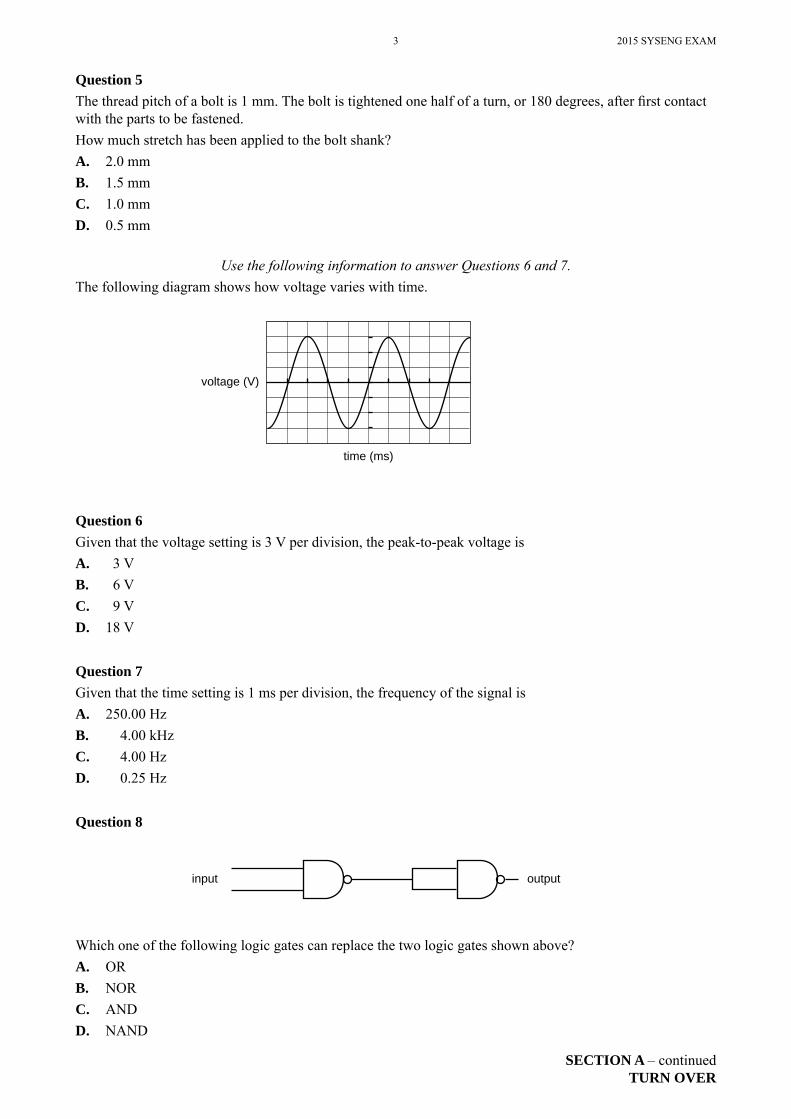
Use the following information to answer Questions 6 and 7.The following diagram shows how voltage varies with time.
time (ms)
voltage (V)
Question 6Given that the voltage setting is 3 V per division, the peak-to-peak voltage isA. 3 VB. 6 VC. 9 VD. 18 V
Question 7Given that the time setting is 1 ms per division, the frequency of the signal isA. 250.00 HzB. 4.00 kHzC. 4.00 HzD. 0.25 Hz
Question 8
input output
Which one of the following logic gates can replace the two logic gates shown above?A. ORB. NORC. ANDD. NAND
2015 SYSENG EXAM 4
SECTION A – continued
Question 9A solar panel has an effi ciency of 30% and its battery has an effi ciency of 90%.What is the combined effi ciency of this system?A. 12%B. 27%C. 30%D. 60%
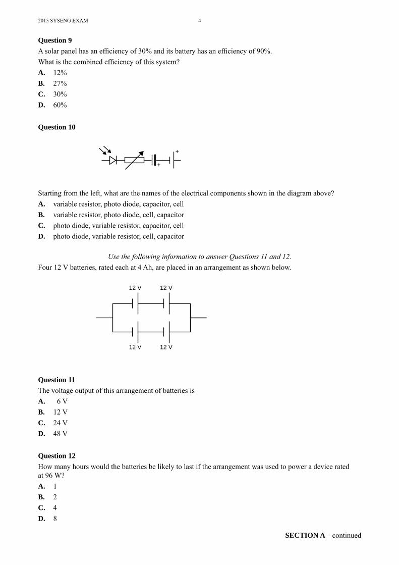
Question 10
+
+
Starting from the left, what are the names of the electrical components shown in the diagram above?A. variable resistor, photo diode, capacitor, cellB. variable resistor, photo diode, cell, capacitorC. photo diode, variable resistor, capacitor, cellD. photo diode, variable resistor, cell, capacitor
Use the following information to answer Questions 11 and 12.Four 12 V batteries, rated each at 4 Ah, are placed in an arrangement as shown below.
12 V 12 V
12 V 12 V
Question 11The voltage output of this arrangement of batteries isA. 6 VB. 12 VC. 24 VD. 48 V
Question 12How many hours would the batteries be likely to last if the arrangement was used to power a device rated at 96 W?A. 1B. 2C. 4D. 8
5 2015 SYSENG EXAM
SECTION A – continuedTURN OVER
Question 13The main role of occupational health and safety (OH&S) guidelines in a workshop is to provideA. rules that users of the workshop must comply with.B. instructions for the operation of all equipment.C. rules for the protection of the teacher.D. recommendations to all users.
Question 14Fire extinguishers used to put out electrical fi res work by removingA. oxygen.B. hydrogen.C. carbon dioxide.D. carbon monoxide.
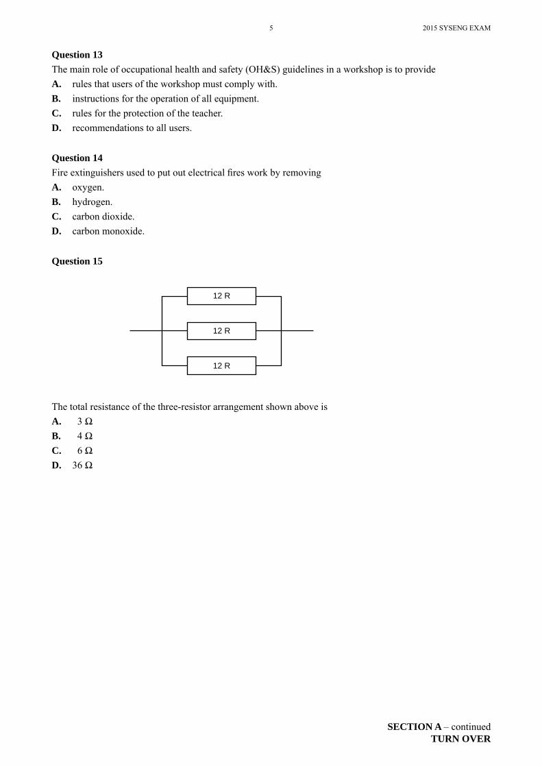
Question 15
12 R
12 R
12 R
The total resistance of the three-resistor arrangement shown above isA. 3 ΩB. 4 ΩC. 6 ΩD. 36 Ω
2015 SYSENG EXAM 6
SECTION A – continued
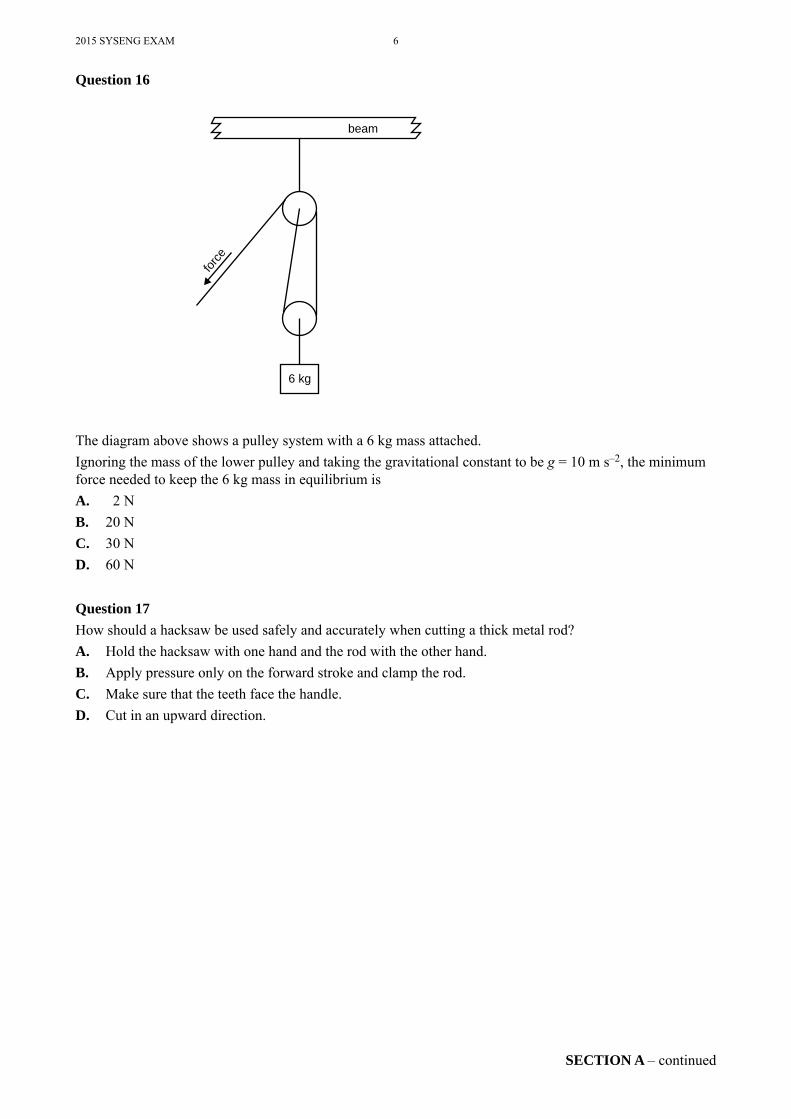
Question 16
force
6 kg
beam
The diagram above shows a pulley system with a 6 kg mass attached.Ignoring the mass of the lower pulley and taking the gravitational constant to be g = 10 m s–2, the minimum force needed to keep the 6 kg mass in equilibrium isA. 2 NB. 20 NC. 30 ND. 60 N
Question 17How should a hacksaw be used safely and accurately when cutting a thick metal rod?A. Hold the hacksaw with one hand and the rod with the other hand.B. Apply pressure only on the forward stroke and clamp the rod.C. Make sure that the teeth face the handle.D. Cut in an upward direction.
7 2015 SYSENG EXAM
END OF SECTION ATURN OVER
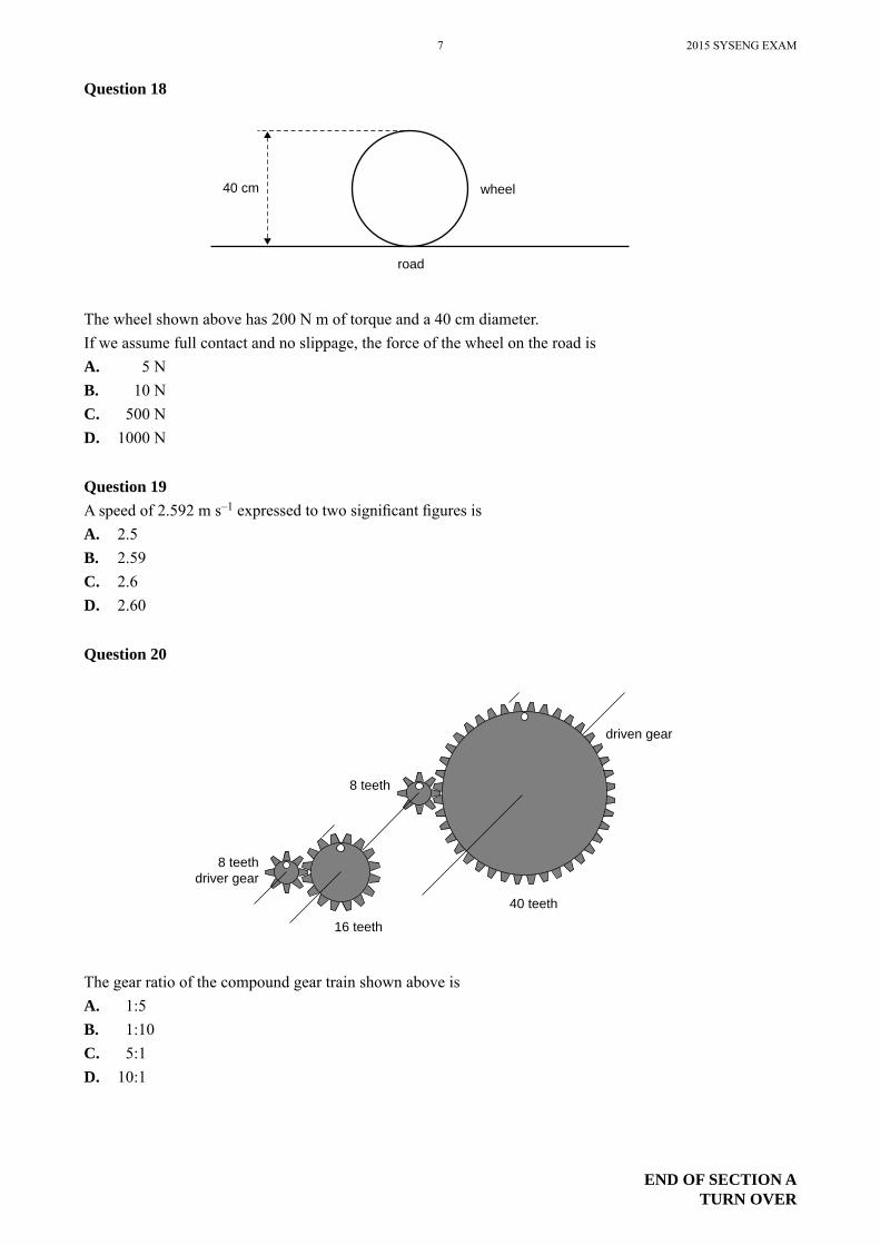
Question 18
40 cm wheel
road
The wheel shown above has 200 N m of torque and a 40 cm diameter.If we assume full contact and no slippage, the force of the wheel on the road isA. 5 NB. 10 NC. 500 ND. 1000 N
Question 19A speed of 2.592 m s–1 expressed to two signifi cant fi gures isA. 2.5B. 2.59C. 2.6D. 2.60
Question 20
driven gear
8 teeth
40 teeth
16 teeth
8 teethdriver gear
The gear ratio of the compound gear train shown above isA. 1:5B. 1:10C. 5:1D. 10:1
2015 SYSENG EXAM 8
SECTION B – continued
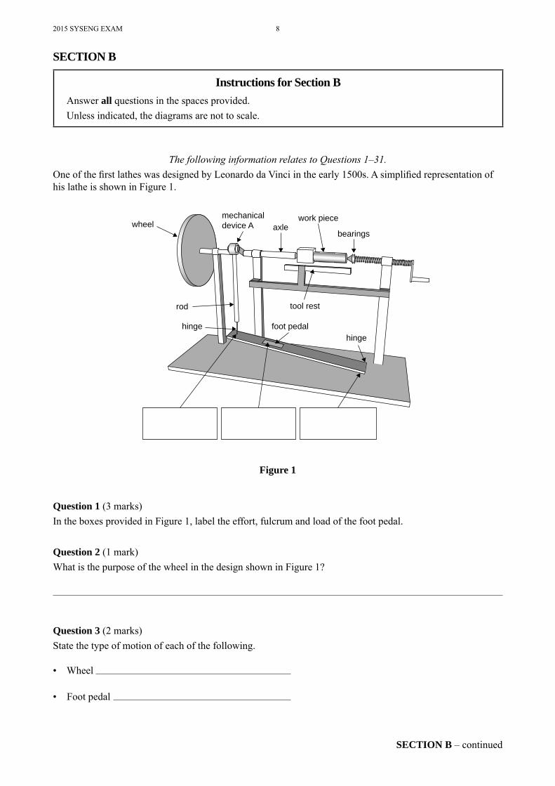
The following information relates to Questions 1–31.One of the fi rst lathes was designed by Leonardo da Vinci in the early 1500s. A simplifi ed representation of his lathe is shown in Figure 1.
wheelmechanicaldevice A axle
bearings
tool rest
foot pedalhinge
hinge
rod
work piece
Figure 1
Question 1 (3 marks)In the boxes provided in Figure 1, label the effort, fulcrum and load of the foot pedal.
Question 2 (1 mark)What is the purpose of the wheel in the design shown in Figure 1?
Question 3 (2 marks)State the type of motion of each of the following.
• Wheel
• Foot pedal
SECTION B
Instructions for Section BAnswer all questions in the spaces provided.Unless indicated, the diagrams are not to scale.
9 2015 SYSENG EXAM
SECTION B – continuedTURN OVER
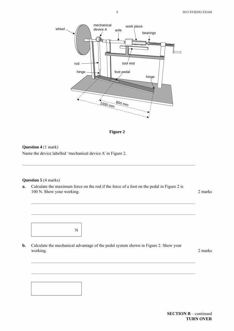
wheelmechanicaldevice A axle
bearings
tool rest
foot pedalhinge
hinge
rod
800 mm1000 mm
work piece
Figure 2
Question 4 (1 mark)Name the device labelled ‘mechanical device A’ in Figure 2.
Question 5 (4 marks)a. Calculate the maximum force on the rod if the force of a foot on the pedal in Figure 2 is
100 N. Show your working. 2 marks
N
b. Calculate the mechanical advantage of the pedal system shown in Figure 2. Show your working. 2 marks
2015 SYSENG EXAM 10
SECTION B – continued
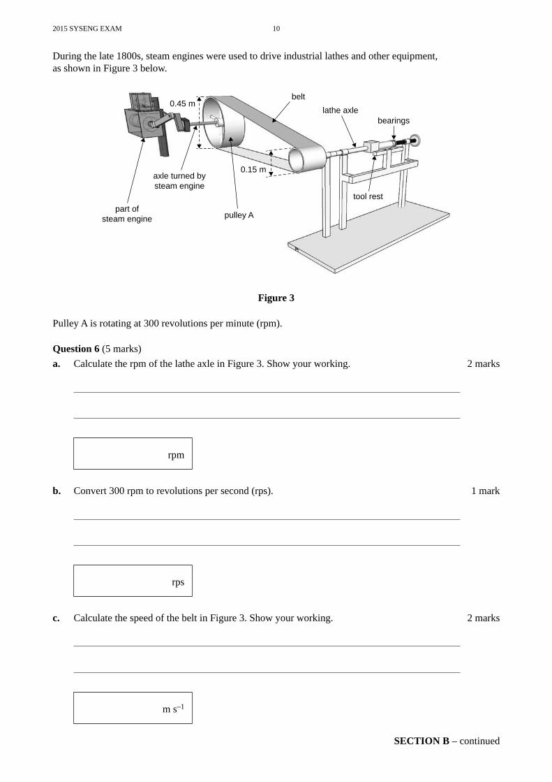
During the late 1800s, steam engines were used to drive industrial lathes and other equipment, as shown in Figure 3 below.
0.45 m
axle turned bysteam engine
part ofsteam engine pulley A
beltlathe axle
tool rest
0.15 m
bearings
Figure 3
Pulley A is rotating at 300 revolutions per minute (rpm).
Question 6 (5 marks)a. Calculate the rpm of the lathe axle in Figure 3. Show your working. 2 marks
rpm
b. Convert 300 rpm to revolutions per second (rps). 1 mark
rps
c. Calculate the speed of the belt in Figure 3. Show your working. 2 marks
m s–1

11 2015 SYSENG EXAM
SECTION B – continuedTURN OVER
Question 7 (1 mark)Given that the steam engine always rotates in the same direction, how could a belt-and-pulley system be modifi ed to reverse the direction of the lathe axle?
Question 8 (1 mark)Give one essential piece of personal safety equipment that must be used when operating a lathe.
2015 SYSENG EXAM 12
SECTION B – continued
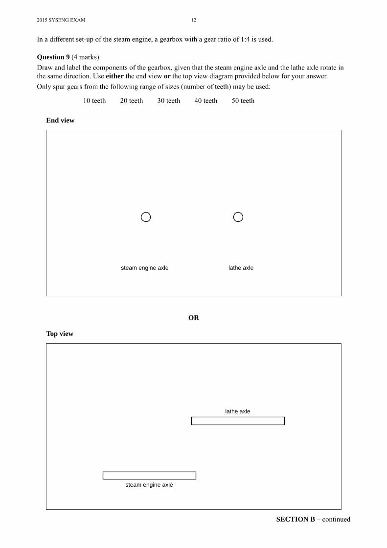
In a different set-up of the steam engine, a gearbox with a gear ratio of 1:4 is used.
Question 9 (4 marks)Draw and label the components of the gearbox, given that the steam engine axle and the lathe axle rotate in the same direction. Use either the end view or the top view diagram provided below for your answer.Only spur gears from the following range of sizes (number of teeth) may be used:
10 teeth 20 teeth 30 teeth 40 teeth 50 teeth
End view
steam engine axle lathe axle
OR
Top view
lathe axle
steam engine axle
13 2015 SYSENG EXAM
SECTION B – continuedTURN OVER
CONTINUES OVER PAGE
2015 SYSENG EXAM 14
SECTION B – continued
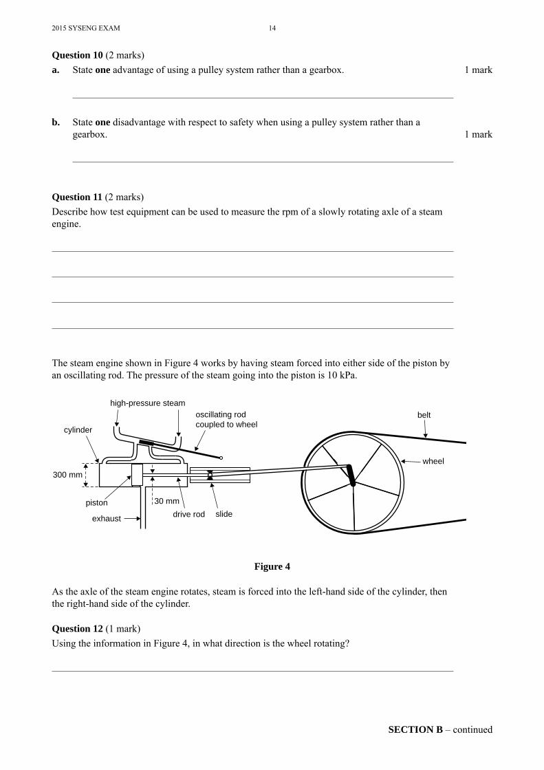
Question 10 (2 marks)a. State one advantage of using a pulley system rather than a gearbox. 1 mark
b. State one disadvantage with respect to safety when using a pulley system rather than a gearbox. 1 mark
Question 11 (2 marks)Describe how test equipment can be used to measure the rpm of a slowly rotating axle of a steam engine.
The steam engine shown in Figure 4 works by having steam forced into either side of the piston by an oscillating rod. The pressure of the steam going into the piston is 10 kPa.
high-pressure steamoscillating rod coupled to wheelcylinder
300 mm
piston
exhaust drive rod slide
belt
wheel
30 mm
Figure 4
As the axle of the steam engine rotates, steam is forced into the left-hand side of the cylinder, then the right-hand side of the cylinder.
Question 12 (1 mark)Using the information in Figure 4, in what direction is the wheel rotating?
15 2015 SYSENG EXAM
SECTION B – continuedTURN OVER
Question 13 (3 marks)Calculate the force on the piston in Figure 4 as steam enters the left-hand side of the cylinder.
N
Question 14 (1 mark)Why is the force on the piston in Figure 4 greater when the piston moves to the right compared to when the piston moves to the left?
Question 15 (4 marks)a. State two environmental issues that should be considered when using a wood-fi red steam
engine to power a lathe. 2 marks
1.
2.
b. State two environmental issues that should be considered when using mains electricity to power a lathe. 2 marks
1.
2.
Question 16 (3 marks)State the type of energy present in each of the following.
• Dry wood
• Steam
• Spinning wheel
2015 SYSENG EXAM 16
SECTION B – continued
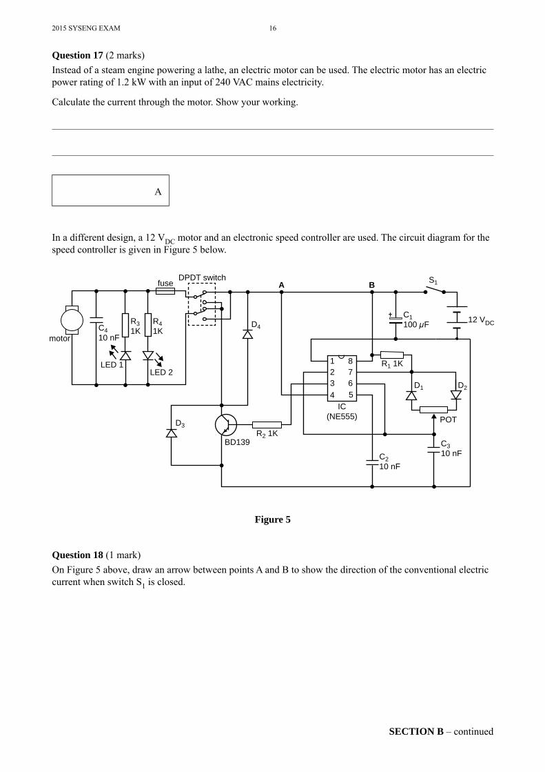
Question 17 (2 marks)Instead of a steam engine powering a lathe, an electric motor can be used. The electric motor has an electric power rating of 1.2 kW with an input of 240 VAC mains electricity.
Calculate the current through the motor. Show your working.
A
In a different design, a 12 VDC motor and an electronic speed controller are used. The circuit diagram for the speed controller is given in Figure 5 below.
1 82 73 64 5
R1 1K
S1
R41K
R31KC4
10 nFmotor
LED 1LED 2
fuseDPDT switch
D4
D3
BD139R2 1K
IC(NE555)
C1100 μF
A B
12 VDC
D1 D2
POT
C310 nFC2
10 nF
Figure 5
Question 18 (1 mark)On Figure 5 above, draw an arrow between points A and B to show the direction of the conventional electric current when switch S1 is closed.
17 2015 SYSENG EXAM
SECTION B – continuedTURN OVER
Question 19 (4 marks)Referring to Figure 5, what do the following stand for?
• LED
• IC
• POT
• μF
Question 20 (1 mark)What is the function of the DPDT switch shown in Figure 5?
Question 21 (1 mark)Referring to Figure 5, resistor R1 has four colour bands with a tolerance of 5%.
Write down the colour bands of R1.
Question 22 (2 marks)Referring to Figure 5, calculate the voltage across resistor R3 if the electric current through LED 1 is 10 mA.
V
Question 23 (1 mark)What is the purpose of LED 1 and LED 2 shown in Figure 5?
2015 SYSENG EXAM 18
SECTION B – continued
Question 24 (2 marks)A digital multimeter set on DC volts is used to measure the voltage across two selected pins of the IC shown in Figure 5.
State the value expected for each of the following selected pairs of pins as the motor operates.
• 1 and 8 V
• 2 and 6 V
Question 25 (4 marks)a. Referring to Figure 5, if LED 1 was not working, what would be two possible faults, apart
from the LED being faulty? 2 marks
1.
2.
b. Give two possible consequences if C4 was short circuited in Figure 5. 2 marks
1.
2.
Question 26 (3 marks)During testing, capacitor C1 is found to be faulty and needs to be replaced. There are only 50 μF or 200 μF capacitors available.
How could 50 μF or 200 μF capacitors be used to take the place of the 100 μF capacitor in Figure 5? Draw a circuit diagram and justify your choice by showing appropriate calculations.
19 2015 SYSENG EXAM
SECTION B – continuedTURN OVER
Question 27 (3 marks)What is one function of each of the following components in an electric circuit?
• Diode
• Transistor
• Capacitor
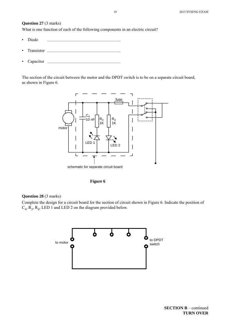
The section of the circuit between the motor and the DPDT switch is to be on a separate circuit board, as shown in Figure 6.
schematic for separate circuit board
motor
C410 nF R3
1KR41K
LED 2LED 1
fuse
Figure 6
Question 28 (3 marks)Complete the design for a circuit board for the section of circuit shown in Figure 6. Indicate the position of C4, R3, R4, LED 1 and LED 2 on the diagram provided below.
to motorto DPDTswitch
2015 SYSENG EXAM 20
SECTION B – continued
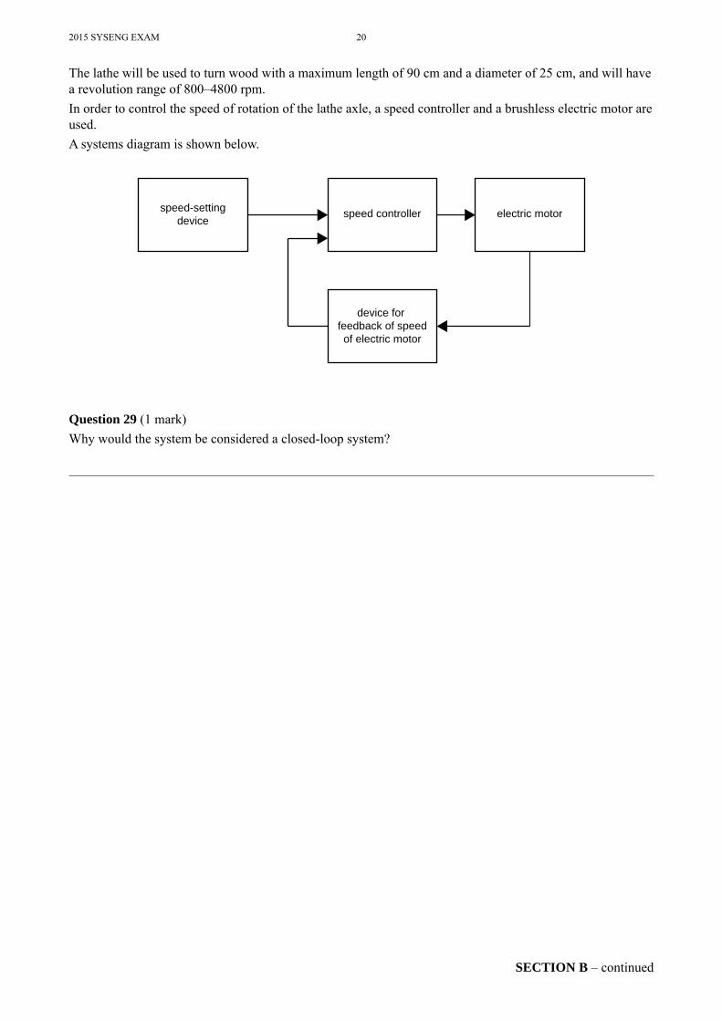
The lathe will be used to turn wood with a maximum length of 90 cm and a diameter of 25 cm, and will have a revolution range of 800–4800 rpm.In order to control the speed of rotation of the lathe axle, a speed controller and a brushless electric motor are used.A systems diagram is shown below.
speed-settingdevice speed controller
device for feedback of speedof electric motor
electric motor
Question 29 (1 mark)Why would the system be considered a closed-loop system?
21 2015 SYSENG EXAM
SECTION B – continuedTURN OVER
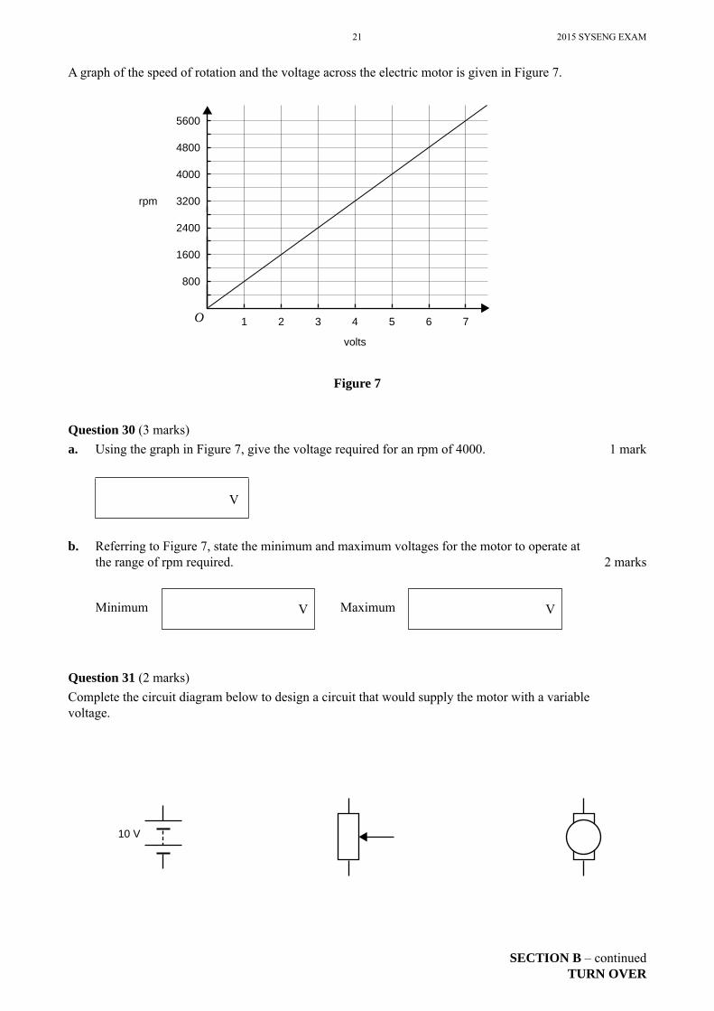
A graph of the speed of rotation and the voltage across the electric motor is given in Figure 7.
volts
1 2 3 4 5 6 7
rpm
800
1600
2400
3200
4000
4800
5600
O
Figure 7
Question 30 (3 marks)a. Using the graph in Figure 7, give the voltage required for an rpm of 4000. 1 mark
V
b. Referring to Figure 7, state the minimum and maximum voltages for the motor to operate at the range of rpm required. 2 marks
Minimum V Maximum V
Question 31 (2 marks)Complete the circuit diagram below to design a circuit that would supply the motor with a variable voltage.
10 V
2015 SYSENG EXAM 22
END OF SECTION B
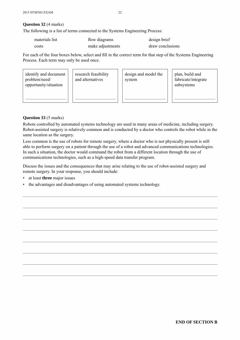
Question 32 (4 marks)The following is a list of terms connected to the Systems Engineering Process:
materials list fl ow diagrams design briefcosts make adjustments draw conclusions
For each of the four boxes below, select and fi ll in the correct term for that step of the Systems Engineering Process. Each term may only be used once.
identify and document problem/need/opportunity/situation
research feasibility and alternatives
design and model the system
plan, build and fabricate/integrate subsystems
Question 33 (5 marks)Robots controlled by automated systems technology are used in many areas of medicine, including surgery. Robot-assisted surgery is relatively common and is conducted by a doctor who controls the robot while in the same location as the surgery.Less common is the use of robots for remote surgery, where a doctor who is not physically present is still able to perform surgery on a patient through the use of a robot and advanced communications technologies. In such a situation, the doctor would command the robot from a different location through the use of communications technologies, such as a high-speed data transfer program.
Discuss the issues and the consequences that may arise relating to the use of robot-assisted surgery and remote surgery. In your response, you should include:• at least three major issues• the advantages and disadvantages of using automated systems technology.
23 2015SYSENGEXAM
END OF QUESTION AND ANSWER BOOK
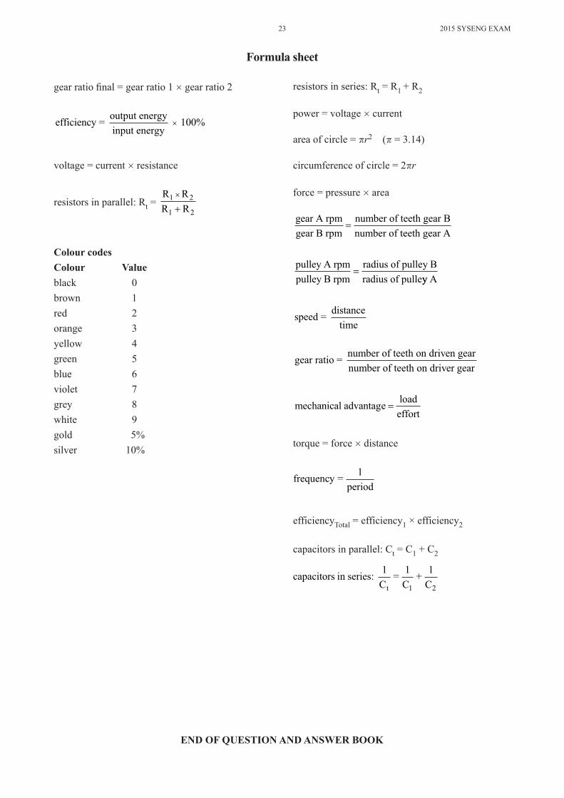
gearratiofinal=gearratio1×gearratio2
efficiency = output energyinput energy
× 100%
voltage=current×resistance
resistorsinparallel:Rt = R RR R
1 2
1 2
×
+
Colour codesColour Valueblack 0brown 1red 2orange 3yellow 4green 5blue 6violet 7grey 8white 9gold 5%silver 10%
resistorsinseries:Rt=R1 +R2
power=voltage×current
areaofcircle=�r2 (�=3.14)
circumferenceofcircle=2�r
force=pressure×area
gear A rpmgear B rpm
number of teeth gear Bnumber of teeth
= gear A
pulley A rpmpulley B rpm
radius of pulley Bradius of pulle
=yy A
speed = distancetime
gear ratio = number of teeth on driven gearnumber of teeth on driver gear
mechanical advantage loadeffort
=
torque=force×distance
frequency = 1period
efficiencyTotal=efficiency1×efficiency2
capacitorsinparallel:Ct=C1+C2
capacitors in series: 1C
= 1C
+ 1Ct 1 2
Formula sheet