©2018 rf ideas configuration utility user manual page
TRANSCRIPT

©2018 RF IDeas Configuration Utility User Manual P a g e | 1
99009230 Rev A

©2018 RF IDeas Configuration Utility User Manual P a g e | ii
Thank You!
Congratulations on the purchase of your Modbus PoE device. RF IDeas hopes you enjoy using the reader as much as we enjoyed creating and developing them. Configuration is easy, so you will be able to quickly take advantage of a more secure environment in your business, school, or organization.
Visit www.RFIDeas.com and follow the Support Learning Center link for more details about our additional product lines.
We look forward to your comments and suggestions for our various product lines. We are always discovering new applications and have several software developer’s licensing our technology so the solution you are looking for may already be developed.
Please call our Sales department if you have any questions or are interested in our OEM and Independent Developer’s programs.
Thank you,
The RF IDeas Staff
Need Assistance?
Phone: +1 (847) 870 - 1723 Toll Free: (866) 439 - 4884
Fax: (847) 483 - 1129 Email: [email protected] Support: [email protected]

©2018 RF IDeas Configuration Utility User Manual P a g e | iii
Glossary of Terms
Terms Definitions
ACP ASCII Command Protocol
BootIP Ethernet Boot Protocol
CSN Card Serial Number
EIP Ethernet Industrial Protocol
PoE Power over Ethernet
PLC Programmable Logic Controller
SDK Software Developer’s Kit – Software Developer’s Kits from RF IDeas provide the high level command capabilities to integrate software applications to our devices.
UID Unique Identifier
Information Symbols
Symbol Meaning Definition
Note Notes are useful information related to the text.
Important Important information can include prerequisites, limitations, and caution.

©2018 RF IDeas Configuration Utility User Manual P a g e | iv
Contents
Glossary of Terms .............................................................................................................................. iii
Information Symbols................................................................................................................................ iii
Chapter 1. The Basics ............................................................................................................................ 1
1.1 Standard ....................................................................................................................................................... 1
1.2 Power Supply ............................................................................................................................................... 1
1.3 Equipment Needed ...................................................................................................................................... 1
Chapter 2. Getting Started..................................................................................................................... 2
2.1 Setting up the Modbus Reader for use ........................................................................................................ 2
2.2 Making the Basic Network Connections ...................................................................................................... 2
2.3 Establishing an IP Address .......................................................................................................................... 2
2.4 Reader Configuration ................................................................................................................................... 3
2.5 Configuring IP & Internal Data Mode Using Web Browser ......................................................................... 3
Configuration Options ........................................................................................................................................................... 4
Internal Mode ........................................................................................................................................................................ 4
2.6 Configuring IP and Internal Data Mode Using a Telnet Session ................................................................. 5
Telnet Menu Options ............................................................................................................................................................ 6
2.7 Configuring the Reader from pcProx® Config Utility .................................................................................... 7
Configuring Multiple Identical Readers ................................................................................................................................. 8
2.8 Configuring the Reader Using ACP Commands ......................................................................................... 9
ACP Overview ...................................................................................................................................................................... 9
Communication ..................................................................................................................................................................... 9
From Windows .................................................................................................................................................................... 10
Command Structure............................................................................................................................................................ 10
Perform a Function ............................................................................................................................................................. 11
Assign a Variable ................................................................................................................................................................ 11
Query a Variable ................................................................................................................................................................. 12
Chapter 3. Modbus Scanner................................................................................................................ 13
3.1 Shortbus Modbus Scanner ........................................................................................................................ 13

©2018 RF IDeas Configuration Utility User Manual P a g e | 1
Chapter 1. The Basics
1.1 Standard
The PoE reader follows the IEEE 802.3af-2003 standard.
1.2 Power Supply
Power is supplied in common mode over two or more of the differential pairs of wires found in the Ethernet cables and comes from a power supply within a PoE-enabled networking device such as an Ethernet switch or can be injected into a cable run with a midspan power supply.
Power is supplied to the reader over the Ethernet connection in common mode over two or more pairs of wires on a PoE enabled network. The power is provided by a PoE router, Ethernet switch or can be injected into the cable with an additional midspan power supply available over the counter in most computer hardware stores or from catalog providers.
1.3 Equipment Needed
• RJ45 patch cable
• PoE capable network port, local router or power injector.
• PC (for initial setup) running: o Microsoft Windows o Shortbus Modbus Scanner o Telnet or other serial communications software and/or pcProxconfig5 application
©2018 RF IDeas Configuration Utility User Manual P a g e | 2
Chapter 2. Getting Started
2.1 Setting up the Modbus Reader for use
The configuration of the reader in most installations requires minimal changes for implementation. However, there are options for configuring the reader. In any situation, setup may need to be done in at least one of the methods described in this manual. Follow the details to establish the communication settings and credential formats you will need to get the end application running right the first time. A typical installation will involve the following:
1. Make basic network connections. 2. Establish an IP address for the reader. 3. Configure the data mode: Listen or Polling 4. Configure the reader credential type(s) and associated data format. 5. Install the reader at the installation site.
2.2 Making the Basic Network Connections
The reader must be connected to a PoE capable connection to provide power to the reader and its communication dongle. For direct connection to the PLC, a simple network crossover cable can be used once the reader is configured.
Connect the reader to the PoE capable port. If one is not available, or for temporary configuration purposes, a power injector can be used. If using a power injector, refer to the manual included with the power injector for instructions on proper connection. Once the PoE network provides power to the reader a beep will be heard and the LED will illuminate red indicating the physical connection has been made and the port is powering the reader.
2.3 Establishing an IP Address
Once the physical connections have been made, the reader will request an IP address from
the router or server. A dynamic address can be assigned by the network. Dynamic addresses can change as other devices are added to the network the PoE device is connected to. Static IP addresses are constant and therefore recommended.
On the administrator PC the DHCP Server may be used to assign an IP address (or use a
standalone BootP server). An IP address pool should be established for large quantity reader
deployment. For a direct reader connection; a static IP address may be required.

©2018 RF IDeas Configuration Utility User Manual P a g e | 3
2.4 Reader Configuration
The reader requires some configuration prior to use. There are many ways to configure the reader. Once assigned, the IP address and internal mode can be configured through a web browser or through telnet to port 9999.
The reader can also be configured to change credential ID types supported, set the device logical unique ID and format the ID data output. To do this the pcProx Configuration utility can be downloaded and connected to a session using port 10001. Or, direct configuration can be performed through a Telnet session to port 9999.
In any situation, the reader will first need to have its IP address assigned and the internal data mode be set.
2.5 Configuring IP and Internal Data Mode Using Web Browser
From the web browser, type in the local IP address assigned to the PoE Modbus reader as shown.
Example: //10.10.10.103
©2018 RF IDeas Configuration Utility User Manual P a g e | 4
Configuration Options
DHCP Enabled: When checked, this will enable the DHCP protocol. Unchecked will allow static IP address configuration.
IP Address: Displays the current IP address in the text box. Here the IP address of the PoE
Reader can be edited if BOOTP is disabled. The address can be either dynamically assigned DHCP or a static IP address.
Subnet Mask: Displays the current Subnet mask in the text box. Here the subnet mask used by the PoE reader can be edited. Typically, the subnet mask will be 255.255.255.0 for most networks.
Gateway: Displays the current Gateway used by the PoE reader. Here the Gateway path can be edited. Set to 0.0.0.0 if the gateway will not be used.
Serial Tunnel TCP Port: Displays the current port address of the serial over Ethernet tunnel. Here the TCP Port used by the serial tunnel can be edited. Default is 10001 and typically does not need to be changed.
The TCP serial tunnel should not be set to port 80, 502, or 9999. Port 80 is reserved for the web configuration menu, port 502 is already permanently configured for MODBUS communication, and 9999 is reserved for the telnet configuration menu.
Internal Mode: Here two radio button choices are shown. Select either “Listen for Card Reads” or “ACP QID Poll” depending on your intended use. See “Configuring the Internal mode”
Internal Mode
By default, the internal data mode is set to Listen Mode. If this is the mode desired and a standard RF IDeas reader is attached (81 in the model name), this step can be skipped. If the reader is a SDK model (82 in the model name) the mode must be set to polling mode.
The PoE for PLC reader module offers two data modes to send data over the Modbus network to the PLC: Listen mode and Polling mode.
Listen Mode: Utilizes the reader’s asynchronous serial communication to send ID data. When an ID is presented under listen mode:
• Sequence number is incremented
• ID bit count field is set to one
• ID data will be present The data sent to the PLC will be valid as long as the ID remains present in the reader’s communication field. Once the card is removed the reader module will clear the ID data available to the PLC. This mode will set a one in the ID Bit Count field when data is available giving a Boolean method of triggering on card presence in addition to the sequence number. Listen mode offers the ability to adjust the data sent from the reader to simplify some programming at the PLC level. The

©2018 RF IDeas Configuration Utility User Manual P a g e | 5
valid ID length can be set in the reader so only valid data lengths are acknowledged when present. Depending on the data sent, listen mode can be the fastest method of retrieving ID data.
Polling Mode: Sets the reader to poll for updated ID data continuously. When an ID is presented to the reader in polling mode:
• Sequence number is incremented
• ID Bit Count Field reports the ID bit count
• ID Data will be present
The data sent to the PLC will be valid as long as the ID remains present in the reader’s
communication field. Once the card is removed the reader module will clear the ID data
available to the PLC. This method offers the addition of an ID Bit Count in the assembly
instance that can be used to verify the ID is the correct data length. The valid ID length can
also be set in the reader so only valid data lengths are acknowledged when present.
2.6 Configuring IP and Internal Data Mode Using a Telnet Session
From Windows, click start > Run and then type CMD to access the command line window.
From the command prompt, type telnet, the assigned IP address of the PoE reader followed by 9999.
Ex: c:\>telnet 52.46.49.44 9999.
Once connected, the user will be prompted to enter setup mode:
This will bring up the configuration menu options. If the telnet session fails to connect, verify the IP address has been entered correctly.
©2018 RF IDeas Configuration Utility User Manual P a g e | 6
Telnet Menu Options
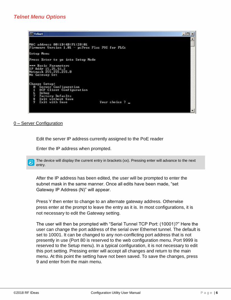
0 – Server Configuration
Edit the server IP address currently assigned to the PoE reader
Enter the IP address when prompted.
The device will display the current entry in brackets (xx). Pressing enter will advance to the next entry.
After the IP address has been edited, the user will be prompted to enter the
subnet mask in the same manner. Once all edits have been made, “set
Gateway IP Address (N)” will appear.
Press Y then enter to change to an alternate gateway address. Otherwise
press enter at the prompt to leave the entry as it is. In most configurations, it is
not necessary to edit the Gateway setting.
The user will then be prompted with “Serial Tunnel TCP Port: (10001)?” Here the
user can change the port address of the serial over Ethernet tunnel. The default is
set to 10001. It can be changed to any non-conflicting port address that is not
presently in use (Port 80 is reserved to the web configuration menu. Port 9999 is reserved to the Setup menu). In a typical configuration, it is not necessary to edit
this port setting. Pressing enter will accept all changes and return to the main
menu. At this point the setting have not been saved. To save the changes, press
9 and enter from the main menu.

©2018 RF IDeas Configuration Utility User Manual P a g e | 7
1 – ACP Client Configuration
Sets the “ACP Client Mode” and “ACP Poll Interscan Delay”. The user can select
either “listen” or “Poll” modes. “Listen” allows the device connected to listen for a
card to be read.
“Polling” allows the user to continuously poll the reader every 250 ms to 2
seconds for changes in the ACP QID (Queued ID).
Pressing 1 and then enter will display “ACP Client Mode (0=Listen, 1=Poll): (1)?”. The default is set to 1.
Pressing enter again will display “ACP Poll Interscan Delay (250..2000 ms):
(250)?
See Input / Output Assembly options
6 – Debug
Sets the PoE to continuously read out the packet transfers. Press Escape to stop the process.
7 – Factory Defaults - Resets the PoE to defaults.
8 – Exit without Save
This option will exit the setup menu without saving any changes made since the start of the session.
9 – Exit with Save
This option will exit the setup menu and save any changes made since the start of the session.
2.7 Configuring the Reader from pcProx® Config Utility
By default, all readers are shipped to detect standard ID formats and a typical data length for the model. Data formatting can be changed to the appropriate format through a variety of commonly used settings to achieve the data output required in the application. The pcProx® Plus line of readers can be configured to the desired ID type by choosing from different standard brands and/or formats.
If additional configuration is necessary for the reader to work in the intended application, this can be done by using the pcProx Config application or directly through the serial over Ethernet tunnel using a telnet session.
©2018 RF IDeas Configuration Utility User Manual P a g e | 8
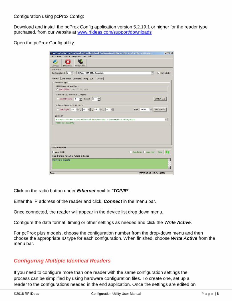
Configuration using pcProx Config:
Download and install the pcProx Config application version 5.2.19.1 or higher for the reader type purchased, from our website at www.rfideas.com/support/downloads
Open the pcProx Config utility.
Click on the radio button under Ethernet next to “TCP/IP”.
Enter the IP address of the reader and click, Connect in the menu bar.
Once connected, the reader will appear in the device list drop down menu.
Configure the data format, timing or other settings as needed and click the Write Active.
For pcProx plus models, choose the configuration number from the drop-down menu and then choose the appropriate ID type for each configuration. When finished, choose Write Active from the menu bar.
Configuring Multiple Identical Readers
If you need to configure more than one reader with the same configuration settings the
process can be simplified by using hardware configuration files. To create one, set up a
reader to the configurations needed in the end application. Once the settings are edited on
©2018 RF IDeas Configuration Utility User Manual P a g e | 9
the first reader by “Write Active”; save them to a template file.
To do so:
1. Click on File>>Save device data to Hwg+ file 2. Type in an easy to remember name for your file. 3. Save the file to a known directory on your PC. 4. Disconnect the reader. 5. Connect the next reader to be configured. 6. Click connect from the menu bar. 7. Choose File>>Open hw/hwg+ file. 8. Navigate to the directory where the file was previously saved. 9. Click on the file and then click open. 10. Click on “Write Active” from the menu bar.
The settings are now activated on the new reader. Repeat this process for each reader in
the installation.
2.8 Configuring the Reader Using ACP Commands
The Modbus PoE for PLC reader uses some ACP commands internally. However, there are many commands that can be used to choose configuration ID types, change data formatting and adjust parity bits among other commands. In listen mode, the reader uses delimiters for framing the ID data. Any changes to pre or post data delimiters will be over-written by the reader. In polling mode, all pre and post delimiters are not used. This manual will provide a brief overview for accessing the commands and their general structure. For more information or to see a full list of available commands, see the ASCII Command Protocol manual.
ACP Overview
ASCII Command Protocol (ACP) allows direct configuration of the device without downloading an application or creating a proprietary interface. The feature is available on CDC, Serial, PoE and Ethernet based readers. The serial Prox reader communicates using ASCII commands.
The reader then parses the command, performs the operation, and may display the result or an error code. All command strings begin with the prefix rfid: and end with a Return key (Enter), CR or LF.
Communication
Modbus and PoE based readers will communicate through a serial tunnel over the Ethernet connection. The Modbus PoE readers will require a telnet session to communicate to the reader.
ACP commands can be sent directly to the reader through the serial tunnel port. This port is defaulted to port 10001 unless changed within the configuration setup menu accessed through the web browser.

©2018 RF IDeas Configuration Utility User Manual P a g e | 10
From Windows
Go to Start Run and type CMD then press Enter to open a dos window (From Windows 7, Go to
Start then type CMD in the search box and press Enter)
At the command prompt, begin a telnet session by typing: telnet {IP address} 10001 where
{IP address} is the IP address assigned to the reader.
Example: c:\>telnet 52.46.49.44 10001
When the telnet session is started, press enter to display the RF IDeas prompt.
At the prompt, type RFID:HELP to see a listing of variables and their command syntax.
To see what the reader is currently set to for the current configuration type RFID:VAR
Make the necessary changes to the reader configuration. Type RFID:CFG.WRITE to save the changes (in RAM) to FLASH memory and activate the settings that were modified.
Command Structure
Commands are not case sensitive. Characters assigned to variables however, are case sensitive.
• All commands begin with rfid followed by one or more token strings with a period delimiter character between multiple tokens.
• Functions must end with a CR or LF.
• Any control characters other than CR, LF, and backspace terminate the command.
• Variables can be assigned a value with an equal sign followed by the value or queried with a question mark.
• The Escape key cancels a command.
©2018 RF IDeas Configuration Utility User Manual P a g e | 11
The general syntax is:
Rfid: TOKEN { DELIMITER TOKEN } { { =Value} | {?} }
Command structure falls into one of three groups:
1. Perform a function. 2. Assign a variable. 3. Query a variable.
Perform a Function
A function performs an operation that may or may not display any results. A function may not be queried. An example of a function is to write the variable settings to flash memory using rfid:cfg.write CR.
Certain functions that display a value or series of values display the string between curly braces for easy parsing. For example, the rfid:qid function output displays:
{0x00BB,1,0x00,80;0x000000801CD1931B2F14}
Assign a Variable
There are three types of variables:
1. Boolean 2. Integer 3. Character
Examples of Boolean Assignments
rfid:op.beep=0 rfid:op.beep=true rfid:op.beep=False rfid:op.beep=F
Examples of Integer Assignment
rfid:out.led=0003 rfid:out.led=3
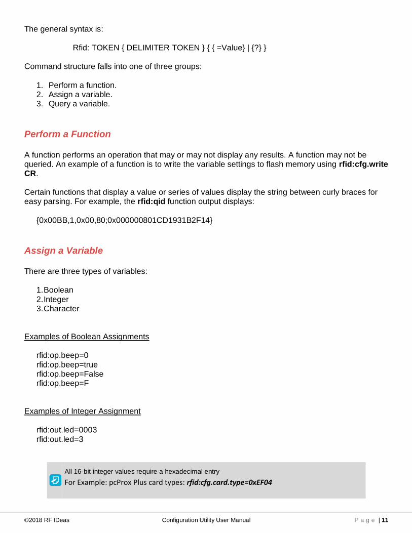
All 16-bit integer values require a hexadecimal entry
For Example: pcProx Plus card types: rfid:cfg.card.type=0xEF04

©2018 RF IDeas Configuration Utility User Manual P a g e | 12
Examples of Character Assignment
rfid:Delim.Chr.fac=’:’ CR rfid:Delim.Chr.fac=’x3a’ CR
Examples of pcProx® Plus Configuration
To set configuration #1 to read Mifare CSN the following commands would be entered:
rfid:cfg=1 CR rfid:cfg.card.type=0x7F41 CR rfid:cfg.write CR
The reader will then respond with {ok}
To then set configuration #2 read HID proxII the following commands would be entered:
rfid:cfg=2 CR rfid:cfg.card.type=0xEF04 CR rfid:cfg.write CR
The reader will then respond with {ok}
Query a Variable
A Variable can be queried to display its current value. Variables are set and stored in RAM and are lost when the utility is closed. Use rfid:var to display the list of current ram settings. The rfid:cfg.write function writes the RAM variables to flash memory. If a variable is changed incorrectly, the settings can be replaced with those from flash using the rfid:cfg.read command.
• The output of the variable displays between curly braces. Example: RF IDeas>rfid:out.led? {3}
Booleans display as true or false.

©2018 RF IDeas Configuration Utility User Manual P a g e | 13
Chapter 3. Modbus Scanner
3.1 Shortbus Modbus Scanner
FIND DEVICE
a. Use Lantronix “Deviceinstaller” to search for Modbus devices. Note the IP address
b. Use a web browser and go directly to the IP address of the device. Change any
parameters desired.
MODBUS SCANNER
a. Use “Shortbus Modbus Scanner” or equivalent
b. Set “Connection” pulldown to TCP and load in TCP address from #1 above
c. Set “Read Function” to FC4 – Input Registers
d. Set “Result Format” to Unsigned Integer 16-bit (or any other preferred date format)
e. Set “Length To Read” to 19
f. Press Connect
g. Present card
MODBUS INPUT REGISTERS
a. Input Register 1: Sequence number (auto increment with each card presented) b. Input Register 2: LUID c. Input Register 3: Bit count

©2018 RF IDeas Configuration Utility User Manual P a g e | 14
d. Input Register 7-19: Card data
MODBUS OUTPUT REGISTERS
a. Holding Register 1: LED Control ▪ bit 0 = red ▪ bit 1 = green ▪ both = yellow
b. Holding Register 2: BEEP Control ▪ 1 – single short beep ▪ 2 – two short beeps ▪ 3 – three short beeps ▪ 4 – four short beeps ▪ 5 – five short beeps ▪ 101 – single long beep ▪ 102 – two long beeps
EXAMPLE: HID PROX READ
a. Card number printed on card is 05607
b. Shortbus read below:
▪ Register 19 is 5607 which is the card number

©2018 RF IDeas Configuration Utility User Manual P a g e | 15
EXAMPLE: BEEP 3 short beeps a. Reconnect Shortbus with only 2 registers, reading the Holding registers in Integer
format b. Double click data in register 2. c. Click check box “Use FC 5/6”. d. Type in 3 for 3 short beeps. e. Click on “Send Write”

©2018 RF IDeas Configuration Utility User Manual P a g e | 16
END-USER LICENSE AGREEMENT LICENSE AGREEMENT
End-User License Agreement for RF IDeas™ SOFTWARE and HARDWARE - RF IDeas’ pcProx®, Proximity Activated Readers, Software Developer’s Kit, and Proximity
Reader DLLs, and Protocol(s).
IMPORTANT-READ CAREFULLY: This End-User License Agreement (“EULA”) is a legal agreement between you (either an individual or a single entity) and the
manufacturer RF IDeas (“Manufacturer”) with which you acquired the RF IDeas software and hardware product(s) identified above (“PRODUCT”). The PRODUCT includes
the RF IDeas reader, computer software, the associated media, any printed materials, and any “on line” or electronic documentation. The SOFTWARE PORTION OF THE
PRODUCT includes the computer software, the associated media, any printed materials, and any “on line” or electronic documentation. By installing, copying or otherwise
using the PRODUCT, you agree to be bound by the terms of this EULA. If you do not agree to the terms of this EULA, RF IDeas is unwilling to license the PRODUCT to
you. In such event, you may not use or copy the SOFTWARE PORTION OF THE PRODUCT, and you should promptly contact the vendor you obtained this PRODUCT
from for instructions on return of the unused product(s) for a refund.
The products described in this publication are intended for consumer applications. RF IDeas assumes no liability for the performance of product. RF IDeas products are not
suitable for use in life-support applications, biological hazard applications, nuclear control applications, or radioactive areas. None of these products or components,
software or hardware, are intended for applications that provide life support or any critical function necessary for the support of protection of life, property or business
interests. The user assumes responsibility for the use of any of these products in any such application. RF IDeas shall not be liable for losses due to failure of any of these
products, or components of these products, beyond the RF IDeas commercial warranty, limited to the original purchase price.
SOFTWARE PRODUCT LICENSE: The PRODUCT is protected by copyright laws and international copyright treaties, as well as other intellectual property laws and
treaties. The SOFTWARE PORTION OF THE PRODUCT is licensed, not sold.
1. GRANT OF LICENSE. This EULA grants you the following rights: *Software. You may install and use one copy of the SOFTWARE PORTION OF THE PRODUCT on
the COMPUTER. *Network Services. If the SOFTWARE PORTION OF THE PRODUCT includes functionality that enables the COMPUTER to act as a network server, any
number of computers or workstations may access or otherwise utilize the basic network services of that server. The basic network services are more fully described in the
printed materials accompanying the SOFTWARE PORTION OF THE PRODUCT. *Storage/Network Use. You may also store or install a copy of the computer SOFTWARE
PORTION OF THE PRODUCT on the COMPUTER to allow your other computers to use the SOFTWARE PORTION OF THE PRODUCT over an internal network, and
distribute the SOFTWARE PORTION OF THE PRODUCT to your other computers over an internal network.
1.1 General License Grant. RF IDeas grants to an individual, a personal, nonexclusive license to make and use copies of the SOFTWARE PRODUCT for the sole
purposes of designing, developing, and testing your software product(s) that are designed to operate in conjunction with any RF IDeas designed proximity reader product.
You may install copies of the SOFTWARE PRODUCT on an unlimited number of computers provided that you are the only individual using the SOFTWARE PRODUCT. If
you are an entity, RF IDeas grants the right to designate one individual within your organization to have the sole right to use the SOFTWARE PRODUCT in the manner
provided above.
1.2 Documentation. This EULA grants an individual, a personal, nonexclusive license to make and use an unlimited number of copies of any documentation, provided that
such copies shall be used only for personal purposes and are not to be republished or distributed (either in hard copy or electronic form) beyond the user’s premises and
with the following exception: you may use documentation identified in the SOFTWARE PRODUCT as the file format specification for RF IDeas’ proximity readers solely in
connection with your development of software product(s) or an integrated work or product suite whose components include one or more general purpose software
products.
1.3 Storage/Network Use. You may also store or install a copy of the SOFTWARE PRODUCT on a storage device, such as a network server, used only to install or run
the SOFTWARE PRODUCT on computers used by a licensed end user in accordance with Section 1.1. A single license for the SOFTWARE PRODUCT may not be
shared or used concurrently by other end users.
1.4 Sample Code. RF IDeas grants you the right to use and modify the source code version of those portions of the SOFTWARE PRODUCT identified as “Samples in the
SOFTWARE PRODUCT (“Sample Code”) for the sole purposes to design, develop, and test your software product(s), and to reproduce and distribute the Sample Code,
along with any modifications thereof, only in object code form.
2. DESCRIPTION OF OTHER RIGHTS AND LIMITATIONS. *Limitations on Reverse Engineering, De-compilation and Disassembly. You may not reverse engineer,
decompile, or disassemble the PRODUCT, except and only to the extent that such activity is expressly permitted by applicable law notwithstanding this limitation *You
may not reproduce or otherwise emulate, in whole or in part, any form the protocol(s) defined within this PRODUCT for use without a RF IDeas PRODUCT Redistributable
Code. If you are authorized and choose to redistribute Sample Code (“Redistributables”) as described in Section 1.4, you agree to: (a) distribute the Redistributables in
object code only in conjunction with and as a part of a software application product developed by you using the PRODUCT accompanying this EULA that adds significant
and primary functionality to the SOFTWARE PRODUCT (“Licensed Product”); (b) not use RF IDeas’ name, logo, or trademarks to market the Licensed Product; (c) include
a valid copyright notice on the Licensed Product; (d) indemnify, hold harmless, and defend RF IDeas from and against any claims or lawsuits, including attorney’s fees, that
arise or result from the use or distribution of the Licensed Product; (e) otherwise comply with the terms of this EULA; and (g) agree that RF IDeas reserves all rights not
expressly granted. You also agree not to permit further distribution of the Redistributables by your end users except: (1) you may permit further redistribution of the
Redistributables by your distributors to your end-user customers if your distributors only distribute the Redistributables in conjunction with, and as part of, the Licensed
Product and you and your distributors comply with all other terms of this EULA; and (2) in the manner described in Section 1.4.
*Separation of Components. The PRODUCT is licensed as a single product. Its component parts may not be separated for use on more than one computer.
*Single COMPUTER. The PRODUCT is licensed with the COMPUTER as a single integrated product. The PRODUCT may only be used with the COMPUTER.
*Rental. You may not rent or lease the PRODUCT without permission from RF IDeas.
*Software Transfer. You may permanently transfer all of your rights under this EULA only as part of a sale or transfer of the COMPUTER, provided you retain no copies,
you transfer all of the PRODUCT (including all component parts, the media and printed materials, any upgrades, this EULA and, if applicable, the Certificate(s) of
Authenticity), AND the recipient agrees to the terms of this EULA. If the PRODUCT is an upgrade, any transfer must include all prior versions of the PRODUCT.
*Termination. Without prejudice to any other rights, RF IDeas may terminate this EULA if you fail to comply with the terms and conditions of this EULA. In such event, you
must destroy all copies of the SOFTWARE PORTION OF THE PRODUCT and all of its component parts.
3. UPGRADES. If the SOFTWARE PORTION OF THE PRODUCT is an upgrade from another product, whether from RF IDeas or another supplier, you may use or
transfer the PRODUCT only in conjunction with that upgraded product, unless you destroy the upgraded product. If the SOFTWARE PORTION OF THE PRODUCT is an
upgrade of a RF IDeas product, you now may use that upgraded product only in accordance with this EULA. If the SOFTWARE PORTION OF THE PRODUCT is an
upgrade of a component of a package of software programs which you licensed as a single product, the SOFTWARE PORTION OF THE PRODUCT may be used and
transferred only as part of that single product package and may not be separated for use on more than one computer.
4. OEM COPYRIGHT. All title and copyrights in and to the PRODUCT (including but not limited to images, photographs, animations, video, audio, music, text and
“applets,” incorporated into the PRODUCT), the accompanying printed materials, and any copies of the SOFTWARE PORTION OF THE PRODUCT, are owned by RF

©2018 RF IDeas Configuration Utility User Manual P a g e | 17
IDeas or its suppliers. The PRODUCT and SOFTWARE PORTION OF THE PRODUCT is protected by copyright laws and international treaty provisions. You may not
copy the printed materials accompanying the PRODUCT.
5. DUAL-MEDIA SOFTWARE. You may receive the SOFTWARE PORTION OF THE PRODUCT in more than one medium. Regardless of the type or size of medium you
receive, you may use only one medium that is appropriate for your single computer. You may not use or install the other medium on another computer. You may not loan,
rent, lease, or otherwise transfer the other medium to another user, except as part of the permanent transfer (as provided above) of the SOFTWARE PORTION OF THE
PRODUCT.
6. OEM PRODUCT SUPPORT. Product support for the product is not provided by RF IDeas or its subsidiaries. For product support, please refer to the OEM supplies
support number provided in the documentation. Should you have any questions concerning the EULA, or if you desire to contact OEM for any other reason, please refer to
the address provided in the documentation provided.
FOR THE LIMITED WARRANTIES AND SPECIAL PROVISIONS PERTAINING TO YOUR PARTICULAR JURISDICTION, PLEASE REFER TO YOUR WARRANTY
BOOKLET INCLUDED WITH THIS PACKAGE OR PROVIDED WITH THE SOFTWARE PRODUCT PRINTED MATERIALS.
Limited Warranty: RF IDeas warrants to the original buyer of this product, that the hardware and related disk(s) are free of defects in material and workmanship for a
period of one year from date of purchase from RF IDeas or from an authorized RF IDeas dealer. Should the RF IDeas products fail to be in good working order at any time
during the one-year period, RF IDeas will, at its option, repair or replace the product at no additional charge, provided that the product has not been abused, misused,
repaired or modified. This warranty shall be limited to repair or replacement and in no event shall RF IDeas be liable for any loss of profit or any commercial or other
damages, including but not limited to special, incidental, consequential or other similar claims. No dealer, distributor, company, or person has been authorized to change or
add to the terms of this agreement, and RF IDeas will not be bound by any representation to the contrary. RF IDeas SPECIFICALLY DISCLAIMS ALL OTHER
WARRANTIES, EXPRESSED OR IMPLIED, INCLUDING BUT NOT LIMITED TO IMPLIED WARRANTIES OF MERCHANTABILITY AND FITNESS OF PURPOSE. Since
some states do not allow such exclusion of limitation of incidental or consequential damages for consumer products, check the statute of the state in which your business
resides.
This warranty gives you the specific legal rights in addition to any rights that you have under the laws of the state in which your business resides or operates.
Returns: RF IDeas products which require Limited Warranty service during the warranty period shall be delivered to the nearest authorized dealer or sent directly to RF
IDeas at the address below with proof of purchase and a Return Materials Authorization (RMA) Number provided by RF IDeas Technical Support Dept. Replacement parts
or complete boards become the property of RF IDeas If the returned board or unit is sent by mail, the purchaser agrees to pre-pay the shipping charges and insure the
board or unit or assume the risk of loss or damage which may occur in transit. The purchaser is expected to employ a container equivalent to the original packaging.
Copyright: Copyright by RF IDeas 2013. All rights reserved. Reproduction or distribution of this document in whole or in part or in any form is prohibited without express
written permission from RF IDeas.
Trademarks: All RF IDeas products are trademarks of RF IDeas. All other product names or names are trademarks or registered trademarks of their respective holders.
Applicable Patents: RF IDeas pcProx Plus card readers supporting HID formats retain US Patent No. 5,952,935 and U.S. Patent No. 7,439,862.
Disclaimer: This Reference Guide is printed in the U.S.A. Any resemblance mentioned in the Reference Guide to persons living or dead, or to actual corporations or
products is purely coincidental. RF IDeas believes that the information contained in this manual is correct. However, RF IDeas does not assume any responsibility for the
accuracy of the content of this User Manual, nor for any patent infringements or other rights of third parties. RF IDeas reserves the right to make any modifications in either
product or the manual without giving prior written notification.
FCC Compliance Statement
FCC ID: M9MPCPROXHUSB100 (HID USB Model) FCC ID: M9MPCPROXM101 (Indala Model) FCC ID: M9MRDR6X8X (Kantech, Indala, Casi-Rusco) FCC ID: M9MPCPROXC101 (Casi-Rusco Model) FCC ID: M9MRFID1856I100 (MIFARE/iCLASS Models) FCC ID: M9MRDR7580 (iCLASS MIFARE and Other 13.56MHz) FCC ID: M9MRDR7581 (iCLASS MIFARE and Other 13.56MHz) FCC ID: M9MRDR7081AKE (iCLASS MIFARE and Other 13.56MHz) FCC ID: M9MRDR8XX8U (Plus combo Model) FCC ID: M9MRDR8058X (Multi-protocol Combo Model) FCC ID: M9M758XCCL (MIFARE and Contact Model) FCC ID: M9MRDR80081 (Plus SIO Combo Model) FCC ID: M9MRDR60DX (125kHz USB Dongle Model) FCC ID: M9MOEM805NX (Multi-protocol Combo Model) FCC ID: M9MSB758X (Mifare 13.56MHz) FCC ID: M9MLC6T8X (132 kHz USB Model) FCC ID: M9MLC608XU0 (125 kHz Virtual Com Model) FCC ID: M9MLC6X8X (Multi-protocol 125kHz)
FCC ID: M9MBUPCPROXH100 (HID RS-232 Model) FCC ID: M9MBUPCPROXA100 (AWID) FCC ID: M9MPCPROXP100 (Pyramid) FCC ID: M9MRDR7081 (iCLASS Module based) FCC ID: M9MRDR7P71 (FIPS 201 13.56MHz) FCC ID: M9MRDR7L81 (Legic 13.56MHz) FCC ID: M9MRDR7081AKF (iCLASS MIFARE and Other 13.56MHz) FCC ID: M9MRDR75DX (iCLASS MIFARE and Other 13.56MHz) FCC ID: M9MRDR758X (iCLASS MIFARE and Other 13.56 MHz) FCC ID: M9M8058XCCL (Multi-protocol and Contact Model) FCC ID: M9M7580CCL (MIFARE and Contact Model) FCC ID: M9MRDR70EX (13.56MHz Express Model) FCC ID: M9MLC608X (125KHz USB Model FCC ID: M9MSB708X (iCLASS 13.56MHz) FCC ID: M9MSB6X8X (Multi-protocol 125kHz) FCC ID: M9MLC60DX (125 KHz USB Model) FCC ID: M9MLC758X (13.56 MHz USB Model) FCC ID: M9MLC6X11U (125 kHz USB Model)
FCC ID: M9MLC805X (Multi-protocol Combo Model) FCC ID: M9MHP8058X (Multi-protocol Combo Model) FCC ID: M9MLC7X11U (13.56MHz USB Model)
FCC ID: M9MLC8058U (Multi-protocol Combo Model) FCC ID: M9MLC8008XU (Multi-protocol Combo Model)
“Pursuant to FCC 15.21 of the FCC rules, changes not expressly approved by RF IDeas might cause harmful interference and void the FCC authorization to operate this
product.
Note: This device complies with Part 15 of the FCC Rules and Industry Canada license-exempt RSS standard(s). Operation is subject to the following two conditions: (1)
This device may not cause harmful interference, and (2) this device must accept any interference received, including interference that may cause undesired operation. This
product complies with FCC OET Bulletin 65 radiation exposure limits set forth for an uncontrolled environment.
The reader may not recognize value cards in the presence of high RF fields. If the current reading is erratic, the user shall take the following step: Move the equipment
from any known transmitters nearby. For more information contact Tech Support at (866) 439 - 4884.

©2018 RF IDeas Configuration Utility User Manual P a g e | 18
RF IDeas
© 2018 RF IDeas. All rights reserved.
Specifications subject to change without notice.
Windows is a trademark of Microsoft.
All other trademarks, service marks, and product or service names are property of their respective owners.
Mention of third-party products is for informational purposes only and constitutes neither an endorsement nor a recommendation.
RF IDeas assumes no responsibility with regard to the performance or use of these products.
All understandings, agreements, or warranties, if any, take place directly between the vendors and the prospective users.
Please feel free to call, e-mail, or visit our web site for a full list of applications, products, configuration options, supported cards, and
form factor specifications. Our web site includes application videos, support materials, case studies, and detailed information about our
product line.
Every effort has been made to ensure that the information in this manual is accurate. RF IDeas is not responsible for printing or clerical
errors.