2020 specifications for watermain construction
TRANSCRIPT

These specifications are intended for inclusion into the contract documents. They only address the technical specifications and construction details of the referenced section.
STANDARD SPECIFICATIONS
FOR WATERMAIN CONSTRUCTION
CITY OF PLYMOUTH, MINNESOTA
JANUARY 2020
ENGINEERING DIVISION
3400 PLYMOUTH BLVD.
PLYMOUTH, MN USA 55447-1482 TELEPHONE (763) 509-5500
Chris LaBounty, P.E.
City Engineer
2020 STANDARD DETAIL SPECIFICATION FOR WATERMAIN CONSTRUCTION 02200 - 2
THIS PAGE LEFT BLANK FOR PRINTING

2020 STANDARD DETAIL SPECIFICATION FOR WATERMAIN CONSTRUCTION 02200 - 3
SECTION 02200
STANDARD DETAIL SPECIFICATIONS FOR
WATERMAIN CONSTRUCTION
CITY OF PLYMOUTH, MINNNESOTA USA
JANUARY 2020 INDEX
Print on Blue Paper
02201 SCOPE OF WORK 02202 USE OF EXISTING WATER SYSTEM 02203 SPECIFICATIONS WHICH APPLY 02204 WATERMAIN MATERIALS
.1 Pipe Bedding
.2 Polyvinyl Chloride Pressure Pipe (PVC)
.3 HDPE Pipe
.4 Pipe Restraints
.5 Tracer Wire for Watermain Pipe
.6 Ductile Iron Pipe (DIP)
.7 Gate Valves, Boxes, Valve Box Bases
.8 DIP Fittings
.9 Bolts, Nuts & Roding
.10 Hydrants
.11 Tapping Sleeves and Valves
.12 Building Services and Service Saddles
.13 Insulation
.14 Polyethylene Encasement Material
.15 Sprinkler Systems
.16 Chanel Post & Markers 02205 WATERMAIN INSTALLATION
.1 Working Hours
.2 Inspection and Handling
.3 Installations of Pipe and Fittings
.4 Pipe Laying Operations
.5 Gate Valves, Boxes, Valve Box Bases and Valve Box Clips
.6 Jacking/Boring
.7 Horizontal Directional Boring
.8 Polyethylene Encasement of Pipeline
.9 Reaction Backing
.10 Joining of HDPE Pipe
.11 Remove and Replace Watermain Bolts
.12 Adjust Gate Valve Box
.13 Watermain Stubs Pressure Relieve Provision

2020 STANDARD DETAIL SPECIFICATION FOR WATERMAIN CONSTRUCTION 02200 - 4
02206 WATERMAIN TESTING .1 Pressure Testing of Watermain .2 Conductivity Testing of Watermain .3 Disinfection of Watermain .4 Bacteria Testing of Watermain
02207 MEASUREMENT AND PAYMENT 02208 WATERMAIN DETAILS
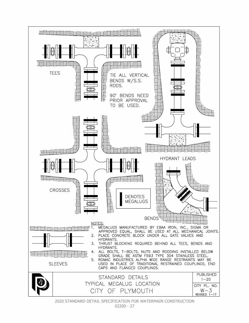
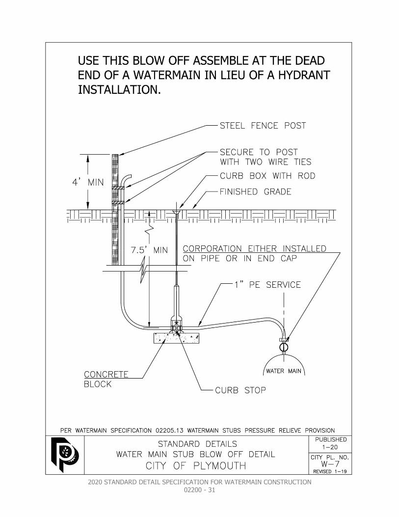
W-1 Sewer and water service connection W-2 Hydrant and gate valve installation W-3 Typical Megalug Location W-4 Gate valve and box installation W-5 Watermain wet tap W-6 Watermain bedding W-7 Watermain stub blow off detail

2020 STANDARD DETAIL SPECIFICATION FOR WATERMAIN CONSTRUCTION 02200 - 5
02201 SCOPE OF WORK The work to be done under this contract shall include the furnishing of all labor, materials, tools and equipment to construct complete in place the watermain and all appurtenances as shown on the drawings, plans and as specified herein. The Contractor shall excavate all materials encountered, furnish and compact foundations where required, furnish and install all timbering, sheeting and bracing necessary to safely support the work, remove any ground water encountered during excavation operations, protect, repair, relocate, maintain and restore all sub-surface, surface and overhead structures directly disturbed, damaged or affected by construction operations and furnish all backfill and other appurtenant items and services as necessary. All site grading must be completed, certified by the project Engineer and all “Off Road” grading equipment removed from the site before starting any public utility work. When installing public utilities in a new residential development all builder and developer construction activity shall pause until the public utilities have been installed, tested and the streets built.
02202 USE OF EXISTING WATER SYSTEM Only designated City personnel shall have the authority to operate any hydrants or valves that make up Plymouth’s water distribution system. Contractors shall not operate existing gate valves or hydrants. It is the Contractors responsibility to make arrangements for receiving water from public or private sources, secure necessary permits and pay regular charges. City water may be purchased at the Public Works facility, 14900 23rd Ave. or at the Zachary Lane Treatment Plant, 4295 Zachary Lane. Under no circumstances shall existing hydrants be used to supply water. City personnel shall do the initial filling of new water mains for service installations and testing. Disposal of any wastewater or any test water into the City sanitary sewer system is not permitted. A minimum of 48-hour notice is required to Plymouth’s utility division if the existing water system requires a shutdown and disruption of service to the existing system customers. In some cases the shutdown may be required to be completed overnight or on weekends depending on the needs of the system customer.

2020 STANDARD DETAIL SPECIFICATION FOR WATERMAIN CONSTRUCTION 02200 - 6
02203 SPECIFICATIONS WHICH APPLY All specifications contained herein, including attached detail drawings, together with the construction plans for the designated project or projects and including current versions of those portions of the following specification, as indicated by paragraph or designation number, shall apply: American Society for Testing Materials (ASTM); American National Standards Institute (ANSI); American Water Works Association (AWWA); Minnesota Department of Transportation “Standard Specifications for Construction” current addition including Special Provisions (MnDOT); and The “City Engineers Association of Minnesota”, Standard Specifications for Utility Construction (CEAM).
02204 WATERMAIN MATERIALS All watermain pipes, hydrants, valves, fittings and all appurtenances shall be new materials, free of any defects and shall be of the type, size, strength, and quality as shown on the plans and as specified herein and/or as indicated in the Special Provisions. The contractor may be required to secure and deliver to the City Engineer or designee a written statement from the manufacturer assuring the quality and compliance to the applicable specification of all materials furnished and installed under this improvement project. This shall in no way relieve the Contractor of any responsibility as to the quality of materials furnished and installed.
02204.1 PIPE BEDDING MATERIAL –Watermain Materials Pipe bedding material shall be in accordance with City Standard detail plate W-6, utilizing sand conforming to MnDOT specification 3149.2B2 or ¾” to 1 ½” clear rock as determined by the existing soils conditions. The contractor shall provide Certification of the materials being used and will be required to perform field sampling for gradation test of any bedding materials used as required by the City Engineer. Copies of test results shall be submitted to the City in a timely manner. Bedding shall be considered incidental to the pipe installation unless noted otherwise in the contract documents. 02204.2 POLYVINYL CHLORIDE PRESSURE PIPE (PVC) –
Watermain Materials PVC Water Main Pipe shall conform to the latest revision of AWWA’s Specification C900 for (4”–12” dia. PVC pipe), C905 for (14”–24” dia. PVC pipe). All 4” to 24” pipe shall be a minimum Pressure Class of 235 psi, DR 18. C909 pipe for (4”-12” dia. PVCO pipe) will be considered in place of C900 with written approval of the City Engineer. All pipes shall be marked with the manufacturer's name, date, nominal size, type of plastic and pressure rating. All PVC pipe used

2020 STANDARD DETAIL SPECIFICATION FOR WATERMAIN CONSTRUCTION 02200 - 7
for potable water lines shall be blue in color. Pipe shall be new, manufactured within the past 12 months as determined from the date stamp on the pipe and free of defects. Pipe will be rejected if surface chalking from UV exposure is visible. Pipe O.D. shall be equivalent to ductile iron pipe of the same nominal size. Maximum length of each PVC section of pipe between elastomeric rings shall be 20 feet (± 1”) for all sizes.
.2A PVC PIPE JOINTS Pipe joints shall consist of an integral wall section with a factory installed, solid cross section elastometric ring which meets the requirements of ASTM F-477. The bell section shall be designed to be at least as hydrostatically strong as the pipe wall and meet the appropriate requirements of AWWA for C900, C905, and C909 pipe.
02204.3 HDPE WATERMAIN PIPE –Watermain Materials HDPE pipe for horizontal directional drilling shall be HDPE AWWA C906 DIPS and a Dimension Ratio (DR) as shown on the drawings. Pipe shall be new, manufactured within the past 12 months as determined from the date stamp on the pipe and free of defects. Pipe will be rejected if surface chalking from UV exposure is visible. The pipe shall contain no recycled compound except that generated in the manufacturer’s own plant. The pipe shall be homogeneous throughout and free of visible cracks, holes, gouges, voids, foreign inclusions, or other defects that may affect the wall integrity. The materials shall be listed by the Plastic Pipe Institute (PPI), a division of the Society of the Plastic Industry in PPI TR-4 with a 73° F hydrostatic design basis of 1,600 psi and a 140° F hydrostatic design basis of 600 psi. The PPI listing shall be in the name of the pipe manufacturer and shall be based in ASTM D 2837 testing.
.3A BUTT FUSION FITTINGS FOR HDPE PIPE HDPE fittings shall be PE4710 HDPE, Cell Classification of 345464C as determined by ASTM D3350-99, and approved for AWWA use. Butt fusion fittings shall have a manufacturing standard of ASTM D3261. Molded & fabricated fittings shall have a pressure rating equal to the pipe unless otherwise specified in the plans. Fabricated fittings are to be manufactured using Data Loggers. Temperature, fusion pressure and a graphic representation of the fusion cycle shall be part of the Quality Control records. All fittings shall be suitable for use as pressure conduits, and per AWWA C906, have nominal burst values of three and one half times the Working Pressure Ratings (WPR) of the fittings.

2020 STANDARD DETAIL SPECIFICATION FOR WATERMAIN CONSTRUCTION 02200 - 8
.3B FLANGED AND MECHANICAL JOINT ADAPTORS Flanged and Mechanical Joint Adaptors shall be PE 3408 HDPE, Cell Classification of 345464C as determined by ASTM D3350-99, Flanged and Mechanical Joint Adapters shall have a manufacturing standard of ASTM D3261. Fittings shall have a pressure rating equal to or greater than the pipe unless otherwise specified on the plans. Backed rings for flanged and mechanical joint adaptors shall be ductile iron, and bolts for fasteners shall be stainless steel, ASTM F 593 Type 304.
02204.4 PIPE RESTRAINTS –Watermain Materials All watermain fittings shall be restrained to the pipe using Megalugs manufactured by EBAA Iron, Inc., “Series 2000PV” restraints for PVC & HDPE pipe and “Series 1100” restraints for DI or CI pipe or Sigma “ONE-LOK” restraints or STAR “Series 4000” for PVC & HDPE pipe and “Series 3000” for DI or CI pipe or approved equal. All vertically installed bends shall be restrained with rodding. 02204.5 TRACER WIRE FOR WATERMAIN PIPE –Watermain
Materials
Tracer wire shall be laid with all watermain and water services regardless of pipe material type and shall be 30 mil insulated, blue colored coating, #10 minimum, solid copper core or #10 minimum, braided stainless steel and rated for underground service. Open trenching shall use minimum 450# break load. Copperhead Industries 7x7 Stranded Copper Clad Steel break load 4700 # minimum, or approved equal tracer wire shall be used for directional boring, pipe bursting or slip lining watermain. The tracer wire loops shall be run up all curb boxes and fire hydrants and connected at a rear flange bolt using an aluminum angle iron hydrant tracer wire bracket part # HTWB-7000 made by “Vait Products” or approved equal. All spliced or repaired wire connections in the tracer wire system shall be made using a Wing Nut Wire Connector (for two to four number ten wires), and made waterproof using an approved buried service wire closure. The buried service wire closure shall be a Klik-It II Number C8816 Buried Service Wire Closure or approved equal. See Standard Detail Plates W-2 & W-5. Tracer wire lengths greater than 500 linear feet without service laterals or hydrants are to include an approved grade level/in-ground access box, located at the edge of the road right-of-way and outside of the roadway. Tracer wire shall be grounded at all terminal ends (stubs, plugs). 02204.6 DUCTILE IRON PIPE (DIP) –Watermain Materials Watermain larger than 24” shall be ductile iron pipe, thickness class 51, tar coated, Polyethylene wrapped in conformance with ANSI/AWWA C105 A21.5, cement lined in conformance with

2020 STANDARD DETAIL SPECIFICATION FOR WATERMAIN CONSTRUCTION 02200 - 9
ANSI/AWWA C104 A21.4; designed to operate at 150 psi plus water hammer.

2020 STANDARD DETAIL SPECIFICATION FOR WATERMAIN CONSTRUCTION 02200 - 10
.6A PIPE JOINTS Pipe joints shall be "Fastite" (American Cast Iron Pipe Company), "Bell-Tite" (James B. Clow and Sons, Inc.) or "Tyton" (U.S. Pipe and Foundry Company), except that mechanical joint, ductile iron, short body fittings, cement lined, Class 250, shall be used for stub ends and all fittings. Copper straps or approved copper tipped gaskets are required.
02204.7 GATE VALVES, BOXES & BOX BASES –Watermain
Materials .7A GATE VALVES American Flow Control 2500 series or Mueller 2360 series resilient seat wedge type gate valves shall be used on all sizes of watermain. See Standard Plates number W-2, W-4 and W-5. No butterfly valves shall be used. Epoxy coating shall be applied to all gate valves, meeting the requirements of AWWA C550. All gate valves shall be assembled with ASTM F 593 Type 304 stainless steel bolts where the bolts are below ground. And all gate valves are to be restrained no matter where they are in the system. Gate valves shall operate smoothly without any binding or hesitation if there are operation issues of any type the valve shall be replaced. Valve boxes and base adaptors are incidental to the valve unless these items are called out in the projects bid-tab. See Standard Detail Plates W-2 and W-4. .7B VALVE BOXES Valve boxes shall be cast iron with #6 bases, screw type round drop cover with “WATER” imprinted on the top. (Refer to Standard Detail Plate W-4). The gate valve box shall consist of extended three piece totaling 7' 6" in standard height, more sections may be added as required for additional depth. No gate valve rod extensions are allowed unless the valve operating nut is greater than 12’ deep. .7C VALVE BOX BASE ADAPTORS Valve boxes bases shall be Adaptor Inc.’s “Valve Box Adaptor II #6 Base” or approved equal.
02204.8 DIP FITTINGS –Watermain Materials DIP Fittings shall be ductile iron casting and have mechanical joints, Class 350 conforming to AWWA specification C153, covering compact fittings. Mechanical joints shall conform to AWWA Specification C111, latest revision, with gaskets made from

2020 STANDARD DETAIL SPECIFICATION FOR WATERMAIN CONSTRUCTION 02200 - 11
vulcanized crude rubber compound. Fittings shall be epoxy coated on the inside and outside. Romac Industries ALPHA “Wide Range Restraints” may be used in place of traditional restrained couplings, end caps and flanged couplings. Mastic spray is to be used where any uncoated pipe or fitting is exposed such as welds, Megalugs, scraped coating, etc. 02204.9 BOLTS, NUTS & RODDING –Watermain Materials All underground installed bolts, T-bolts, nuts and any rodding required shall be stainless steel, ASTM F 593 Type 304 for all watermain fittings including mechanical joints, hydrants, valves, tees, bends, taps, etc. Each bolt shall be clearly stamped as a 593 Type 304 stainless steel bolt. No other type of bolts, nuts or rodding will be allowed unless approved in writing by the City Engineer. Anti-seize bolt/nut coating or spray/paste compound shall be used on all bolting operations. 02204.10 HYDRANTS –Watermain Materials Hydrants shall be Waterous number WB67-250 or CLOW Medallion Hydrants, bright yellow in color. All below grade nuts and bolts shall be ASTM F 593 Type 304 stainless steel. Hydrants in a phased project must all be the same type. Gate valves with valve box bases and valve boxes shall be required for all hydrants. See Standard Detail Plate W-2. Hydrants, hydrant valves and service valves are to be secured to the watermain with MEGALUGS manufactured by EBAA Iron, Inc. or approved equal. Use MEGALUGS at all mechanical joints to tie the hydrant to the gate valve, gate valve to the tee and the tee to the main. DO NOT USE DUC LUGS FOR ANY TYPE OF RESTRAINT. See Standard Detail Plates W-2 and W-3. All hydrant barrels shall be wrapped with Polyethylene encasement. All hydrants will be installed with a reflectorized red and white, plastic composite hydrant locator attached. Exposed fiberglass or metal poles shall not be used. This hydrant locator will be the "Hydrantfinder". See Standard Detail Plate W-2. Hydrants shall be painted yellow from the factory. Yellow paint is Waterous Enamel V1814, Bright Yellow or Sherwin Williams CLOW bright yellow. A hydrant’s paint shall be touched up at the City's discretion.

2020 STANDARD DETAIL SPECIFICATION FOR WATERMAIN CONSTRUCTION 02200 - 12
All hydrants are to be at required height after lawns, boulevards, etc. are finished (sod, mulch, etc.). See Standard Detail Plate W-2. Hydrants shall be “bagged” (covered) with a black poly wrap or approved material immediately after installation and shall remained covered until all testing is complete and they are placed in service. At that time the contractor will be required to remove and dispose of the covering. Hydrant valves, valve boxes, and base adaptors are incidental to the hydrant unless these items are called out in the projects bid-tab. 02204.11 TAPPING SLEEVES AND VALVES –Watermain Materials Tapping sleeves shall be all stainless steel, with flat-faced flange to mate with standard valves. Tapping sleeves and gate valves are required for all taps 4-inches and greater. Taps less than 4 inches shall be provided with a stainless steel service saddle. Tapping sleeves shall be a minimum of 6 feet from pipe joints or other fittings. All bolts and nuts used in conjunction with the tapping sleeve installation shall be ASTM F 593 Type 304 stainless steel. 02204.12 BUILDING SERVICES AND SERVICE SADDLES -
Watermain Materials .12A HDPE SMALL DIAMETER SERVICE PIPE High Density Polyethylene Pipe (HDPE) SDR-9, Copper Tube Size (CTS) pipe shall be used for all small diameter building services conforming to AWWA Specification C901 and ASTM Specification 2737. A minimum of 1” outside diameter service shall be installed. A 1½” or larger outside diameter service shall be installed where fire sprinklers are required or design dictates. Service pipe is to be one continuous piece with no joints or couplings, etc., allowed from main to curb stop. Compression fittings and “Insert Stiffeners” are required at all connections. See Standard Detail Plate W-1.

2020 STANDARD DETAIL SPECIFICATION FOR WATERMAIN CONSTRUCTION 02200 - 13
.12B WATER SERVICE PARTS TABLE The following is a parts list of the components approved for use in a small diameter building water service.
Part # for Smith-Blair
Part # for Romac
Part # for Ford
Part # for McDonald
Part # for
Mueller
1” WATER SVC AWWA C901 SDR 9 CTS
Stainless Steel Service Saddles
372 306 and 305
FS 313 NA NA
Corporation Stops (Ball Valve)
NA NA FB1000-4-G 4701-22 P-25028
Curb Stops (Ball Valve) NA NA B44-444M-G 6104-22 B25155
Curb Stop Boxes 7-1/2’ L Minneapolis Pattern w/rod (1-1/2” base)
NA NA EM2-75-46-72R
5614 H-10300
Curb Stop Caps NA NA PS-LID 5614 89375
1-1/2” WATER SVC AWWA C901 SDR 9 CTS
Stainless Steel Service Saddles
372 306 and 305
FS 313 NA NA
Corporation Stops (Ball Valve)
NA NA FB1000-6-G 4701-22 P-25028
Curb Stops (Ball Valve) NA NA B44-666M-G 6104-22 B-25155
Curb Stop Boxes 7-1/2’ L Minneapolis Pattern w/rod (2” base)
NA NA EM2-75-47-72R
5615 H-10300-99002
Curb Stop Caps NA NA PS-LID 5614 89375
02204.13 INSULATION –Watermain Materials Insulation board (polystyrene) shall meet the requirements of MnDOT 3760. Use a factor of 2 inches of polystyrene equals 1 foot of ground cover when determining thickness requirements. The 4’ x 8’ standard boards shall be orientated to provide a minimum coverage of 1.5’ beyond the outside edge of the pipe being covered. 02204.14 POLYETHYLENE ENCASEMENT MATERIAL –Watermain Materials Polyethylene encasement material shall conform to the requirements of AWWA C-105 for tube type installation and 8 mil nominal film thicknesses. 02204.15 SPRINKLER SYSTEMS –Watermain Materials All materials shall be equal or better quality replacement parts for the existing irrigation system being repaired.

2020 STANDARD DETAIL SPECIFICATION FOR WATERMAIN CONSTRUCTION 02200 - 14
02204.16 CHANNEL POST & MARKERS –Watermain Materials
U-Channel post used for structure marking shall be green, 6ft in length weighting 3lb/ft. and punched full length with 3/8” diameter holes 1” on center. Marker signs shall be 0.063” thick aluminum blanks measuring 3” wide by 8” high with a high intensity blue reflectorized background with white 2” high letters. Markers shall be attached to the post with two stainless steel bolts and nuts. Posts and markers shall be considered incidental unless otherwise noted.
02205 WATERMAIN INSTALLATION 02205.1 WORKING HOURS –Watermain Installation The City Engineer or a designee shall be notified at least 48 hours prior to commencing any work. Phone # (763) 509-5500. Contractors are subject to being shut down and or having work rejected if proper notification is not given to the City. Work shall not commence before 7:00 a.m. nor extend beyond sundown Monday through Friday. On Saturdays, work hours are from 8:00 a.m. to 6:00 p.m. No work is permitted on Sundays or Holidays unless authorized by the City. Existing roadways shall not be restricted between 7 & 9 AM and 3 & 6 PM unless approved by the City Engineer. The definition of “Work” also includes the starting of equipment and the delivery of materials to the job site. 02205.2 INSPECTION AND HANDLING –Watermain Installation Proper and adequate implements, tools, and facilities satisfactory to the City Engineer or a designee shall be provided and used by the Contractor for the safe and convenient prosecution of the work. During the process of unloading, all pipe and accessories shall be inspected by the Contractor for damage. The Contractor shall notify the City Engineer or a designee of all material found to have cracks, flaws or other defects. The City Engineer or a designee shall inspect the damaged materials and have the right to reject any materials found to be unsatisfactory. The Contractor shall promptly remove all rejected material from the site. All materials shall be handled carefully, so as to prevent damage to protective coatings, linings, and joint fillings; preclude contamination of interior areas; and avoid jolting contact, dropping, or dumping. All work and materials are subject to tests by the Owner at such frequency as may be determined by the City Engineer or a designee.
2020 STANDARD DETAIL SPECIFICATION FOR WATERMAIN CONSTRUCTION 02200 - 15
While suspended and before being lowered into laying position, each pipe section and appurtenant unit shall be inspected by the Contractor to detect damage or unsound conditions that may need corrective action or be cause for rejection. The Contractor shall inform the City Engineer or a designee of any defects discovered and the City Engineer or a designee will prescribe the required corrective actions or order rejection. Immediately before placement, the joint surfaces of each pipe section and fitting shall be inspected for the presence of foreign matter, coating blisters, rough edges or projections, and any imperfections so detected shall be corrected by cleaning, trimming, or repair as needed. 02205.3 INSTALLATION OF PIPE AND FITTINGS –Watermain
Installation All site grading must be completed, certified by the project Engineer and all “Off Road” grading equipment removed from the site before starting any public utility work.
Watermain and water services shall be placed with a minimum of 7.5 feet of ground cover from the top of pipe to finished grade. A minimum vertical separation of eighteen inches (18") must be provided between the outer surfaces of the pipes, with preference that the watermain cross above the sewer, wherever possible. One full length of water pipe shall be located so both joints will be as far from the sewer as possible.
Watermain that is installed on a vertical slope with a 10% grade or steeper shall have all the joints along that slope tied.
Hydrants shall not be installed on the same side of the street as the sidewalk or trail. If an existing property’s service is to be interrupted notify the property owner 48 hours in advance. Interruption of existing service shall be confined to between the hours of 9 AM and 4 PM. Water services shall be extended from the main to the back of the 10-foot easement where the curb stop will be placed. Minimum size of service is 1” O.D. A 1½” O.D. or larger diameter service shall be installed where fire sprinklers are required or design dictates. See Standard Detail Plate W-1. Installation of Polyethylene Pipe (HDPE) and their appurtenances shall conform to the requirements of AWWA C906. The installation

2020 STANDARD DETAIL SPECIFICATION FOR WATERMAIN CONSTRUCTION 02200 - 16
shall be to the bedding and backfill conditions specified by the Manufacturer, Plans, Specifications, or Special Provisions. AWWA C900, C905 and C909 pipe should be installed in accordance with AWWA C605 “Underground Installation of Polyvinyl Chloride (PVC) Pressure Pipe and Fittings for Water.” The installation shall be to the bedding and backfill conditions specified by the Plans, Specifications, or Special Provisions. Installation of ductile iron water mains (DIP) and their appurtenances shall conform to the requirements of AWWA C-600 Specifications, the Plans, Specifications and Special Provisions. In low-pressure areas, above elevation 1040 feet above sea level, the City will require pressure booster pumps within the structure at the service entrance. The City’s Building Division codes shall apply for this requirement.
02205.4 PIPE LAYING OPERATIONS –Watermain Installation Trench excavation and bedding preparations shall proceed ahead of pipe placement so as to permit proper placement and joining of the pipe and fittings at the prescribed grade and alignment without unnecessary hindrance. All foreign matter or dirt shall be removed from the inside of the pipe and fittings before they are lowered into position in the trench, and they shall be kept clean by approved means during and after the laying operation. The water main materials shall be carefully lowered into laying position by the use of suitable restraining devices. Under no circumstances shall the pipe be dropped or dumped into the trench. Placement of public PVC or H.D.P.E pipe shall not occur after November 30th or before March 31st. At the time of pipe placement, the bedding conditions shall be such as to provide uniform and continuous support for the pipe between bell holes. Bell holes shall be excavated as necessary to make the joint connections, but they shall be no larger than would be adequate to support the pipe throughout its length. No pipe material shall be laid in water or when the trench or bedding conditions are otherwise unsuitable or improper. Maintain a minimum 18” of separation between the watermain and all other utility pipes. When placement or handling precautions prove inadequate, in the City Engineer or a designee’s, opinion, the Contractor shall provide

2020 STANDARD DETAIL SPECIFICATION FOR WATERMAIN CONSTRUCTION 02200 - 17
and install suitable plugs or caps, effectively closing the open ends of each pipe section before it is lowered into laying position, and they shall remain so covered until removal is necessary for connection of an adjoining unit. Tracer wire shall be placed along the side of the pipe and secured every 10 feet to the pipe with duct tape. Tracer wire shall be brought up alongside each hydrant barrel. The tracer wire to the hydrant shall be run inside a 3’ long section of 1” PE water service pipe from the terminus on the hydrant, down two feet into the soil. See details W2 for additional information. As each length of bell and spigot pipe is placed in laying position, the spigot end shall be centered in the bell and the pipe forced home and brought to correct line and grade. The pipe shall be secured in place with approved backfill material, which shall be thoroughly compacted by tamping around the pipe to a height of at least 12 inches above its top. Mechanically compact all trenches in accordance with MnDOT 2105. At all times when pipe laying is not in progress, including noon hour and overnight periods, all open ends of the pipe line shall be closed by watertight plugs or other means approved by the City Engineer or a designee. If water is present in the trench, the seals shall remain in place until the trench is pumped completely dry. When connecting to existing stubs, the Contractor shall take every precaution necessary to prevent dirt or debris from entering the existing lines. All necessary work to make the connection shall be done at no additional compensation, except where noted otherwise. 02205.5 GATE VALVES, BOXES, VALVE BOX BASES–Watermain
Installation All hydrants shall have a tracer wire run up along the barrel and terminated at a bracket on a top back flange bolt. Box bases shall be placed on “Adaptors Inc.” #6 valve box adaptor base or approved equal. Valve boxes shall be installed plumb and square to the valve operating nut. All off road valve boxes, except for those on hydrant leads, shall be marked with a flange post and a blue reflectorized metal marker plate with white “G.V.” lettering printed upon the plate. Marker plate shall be attached to the flange post using stainless steel bolts and nuts. The marker plate shall face the closest access road. The flange post shall be located 2’ behind the box when facing the roadway. 02205.6 Jacking/Boring – Watermain Installation

2020 STANDARD DETAIL SPECIFICATION FOR WATERMAIN CONSTRUCTION 02200 - 18
The terms "auger", "boring", "jack", "jacking", and "tunneling" in the proposal, specifications, and plans refers only to non-open cut construction. The Contractor shall inspect and verify soil conditions to his own satisfaction in order to determine the type of construction to employ. During the construction, the Contractor shall be responsible for protecting all existing utilities above or below the pipe invert. The minimum inside diameter of the casing pipe shall be four (4) inches greater than the outside diameter of the bell of the carrier pipe. For any installation beneath a railroad, the top of the casing pipe shall not be closer than the specified dimensions indicated in the railroad permit. The steel casing minimum wall thickness shall be as specified on the Plans, in the Special Provisions, or in the applicable Permit. Where required by the City Engineer or a designee, two 17-pound anode packs shall be attached to the casing for corrosion protection. A 1-1/2 inch pipe shall be forced along the top of the casing pipe. The front end of this pipe shall be 18 inches behind the front end of the casing pipe. A mixture of water and bentonite clay shall be forced through this pipe at all times during the casing installation to fill any voids that may be present above the casing pipe. Upon completion of the casing installation, this pipe shall be slowly withdrawn while bentonite is forced through the pipe to fill any remaining voids. The Contractor shall prevent excavated materials from flowing back into the excavation during the non-open cut construction. This shall include the use of a shield conforming to the size and shape of the casing that will prevent materials from flowing into the leading edge of the casing. The jacking machine used shall be capable of controlling line and grade and shall conform to the size and shape of the casing pipe. No jacking/auguring of pipe will be allowed below the water table unless the water table has been lowered sufficiently to keep the water below the pipe being installed. The use of water under pressure (jetting) or puddling will not be permitted to facilitate jacking/auguring operations. If any installation is augured, the head shall be approved by the City Engineer or a designee and the auger shall be located six (6) inches behind the lead edge of the casing or carrier pipe.
2020 STANDARD DETAIL SPECIFICATION FOR WATERMAIN CONSTRUCTION 02200 - 19
If a void develops, the jacking/auguring shall be stopped immediately and the void shall be filled by pressure grouting. The grout material shall consist of a sand/cement slurry of at least two sacks of cement per cubic yard and a minimum of water to assure satisfactory placement. Skids and blocking shall be used as necessary to install the carrier pipe to the proper line and grade inside the casing pipe. Voids between carrier and casing pipes shall be filled with sand and the casing pipe sealed at both ends with a suitable material to prevent water or debris from entering the casing pipe.
02205.7 HORIZONTAL DIRECTIONAL BORING –Watermain
Installation Directional boring/drilling installation shall be accomplished where required on the Plans or in the Special Conditions to minimize disturbance of existing surface improvements. The Contractor shall be compensated for the restoration work only within the areas at the connection points, or other locations as may be approved by the City Engineer or a designee. The Contractor shall be responsible for repairs, without compensation, for any other repair areas, including pit/boring points and areas above the drilled pipe where underground pressure may cause heaving or damage to pavement and ground surfaces. The contractor must submit boring/drilling pit locations to the City Engineer or a designee for approval before beginning construction. Boring pits may be located within roadway right-of-way and easements as authorized by the City of Plymouth. Any other locations that may be desired by the contractor for boring pits or other uses shall be the responsibility of the Contractor to attain authorization, including private property as may be required. The drilling equipment shall be capable of placing the pipe as shown on the plans. The installation shall be by a steerable drilling tool capable of installing continuous runs of pipe without intermediate pits, at a minimum distance and radius requirements per the manufacturer’s specification and recommendations. The guidance system shall be capable of installing pipe within 6-inches of the plan vertical dimensions and 12-inches of the plan horizontal dimensions. The Contractor shall be required to remove and reinstall pipe, which vary in depth and alignment from these tolerances. Copperhead Industries 7x7 Stranded Copper Clad Steel break load 4700 # minimum, tracer wire or approved equal shall be pulled along

2020 STANDARD DETAIL SPECIFICATION FOR WATERMAIN CONSTRUCTION 02200 - 20
with the HDPE pipe in order to locate it in the future. Conductivity between HDPE and ductile iron pipe shall be continuous. Pull back forces shall not exceed the allowable pulling forces for the pipe being installed. The minimum radius of the pipe shall be per the manufacturer’s specification and recommendations. Drilling fluid shall be a mixture of water and bentonite clay and shall be designed for existing soil conditions. Disposal of excess fluid and spoils shall be the responsibility of the Contractor.
02205.8 POLYETHYLENE ENCASEMENT OF PIPELINE –Watermain Installation For DIP watermain wherever so required by the Plans, Specifications, or Special Provisions, the pipeline, including valves, fittings, hydrant barrels, and appurtenances, shall be fully encased in polyethylene film meeting the requirements of these Specifications. The film shall be furnished in tube form for installation on pipe and all pipe-shaped appurtenances such as bends, reducers, off- sets, etc. Sheet film shall be provided and used for encasing all odd-shaped appurtenances such as valves, tees, crosses, etc. 02205.9 REACTION BACKING –Watermain Installation Reaction backing shall be provided at all watermain fittings and at the hydrant in accordance with the typical backing detail shown on the standard details. In any instance where the City Engineer or a designee determines that solid backing against undisturbed earth is not obtainable for fittings or hydrants, the Contractor shall use stainless steel tie rods, ASTM F 593 Type 304 and or mechanical joint retainer glands as directed by the City Engineer or a designee. All vertical bends shall be secured with both mechanical joint retainer glands and two (2) stainless steel tie rods. Mechanical joint retainer glands shall be tied to an adjacent fitting or back one full length of pipe. Bends larger than 45 degrees shall not be used without approval of the City Engineer or a designee. 02205.10 JOINING OF HDPE PIPE –Watermain Installation Sections of polyethylene pipe shall be joined by the butt fusion process into continuous lengths at the job site. Extrusion welding or hot gas welding of HDPE shall not be used. Butt fusion shall be performed only by a certified thermal fusion Contractor. The Contractor’s certification shall be submitted to the City Engineer or a designee for review and approval prior to the start of construction. The joining method shall be the butt fusion method and shall be performed in strict accordance with the pipe manufacture’s recommendations. The butt fusion equipment used in the joining procedures should be capable of meeting all conditions
2020 STANDARD DETAIL SPECIFICATION FOR WATERMAIN CONSTRUCTION 02200 - 21
recommended by the pipe manufacturer. The Contractor shall be responsible to verify that the fusion equipment is in good operating condition and that the operator has been trained within the past twelve months. All welds will be made using a Data Logger to record temperature, fusion pressure, with a graphic representation of the fusion cycle shall be part of the Quality Control records. Flanges/MJ adapters shall be attached to pipe fittings using butt fusion. The flanges/MJ adapters shall be aligned and centered relative to the pipe. Flanges/MJ adapters should be square with the valve or other flange before tightening of bolts. Bolts should not be used to draw flanges into alignment. Bolt threads shall be lubricated, and flat washers shall be used under flange nuts. Bolts shall be tightened using a “star tightening pattern”. See manufacturer’s recommendations. Twenty-four hours after first tightening the flange bolts, they must be re-tightened using the same “star tightening pattern” used above. The final tightening torque shall be as indicated by the manufacturer. Polyethylene pipe and fittings may be joined using approved electro fusion couplings where the butt fusion method cannot be used. Fittings shall be PE3408 HDPE, Cell Classification of 345464C as determined by ASTM D3350-99. Electro fusion Fittings shall have a manufacturing standard of ASTM F1055. Fittings shall have a pressure rating equal to the pipe unless otherwise specified on the plans. All electro fusion fittings shall be suitable for use as pressure conduits, and per AWWA C906, have nominal burst values of three and one-half times the Working Pressure Rating (WPR) of the fitting. Mechanical joining may be used where the butt fusion or electro fusion methods cannot be used. Mechanical joining will be accomplished by either using a HDPE flange adapter with Ductile Iron back-up ring or HDPE Mechanical Joint adapter with a Ductile Iron back-up ring. Refer to the manufacturer’s recommendations. Pipe stiffeners shall be used where stiffening of the pipe is necessary for proper gasket seal. Pipe Stiffeners shall be ASTM-240-TP-304 Stainless Steel. 02205.11 REMOVE AND REPLACE WATERMAIN BOLTS
.A Replace watermain bolts with ASTM F 593 Type 304
stainless steel bolts while watermain is live. Replace only one bolt at a time. Apply anti-seize on stainless steel bolts. .B Replace top plate bolts first with valve pinched wide open. Typically there are 4 top plate bolts per valve. .C Replace the bolt inside of the top nut.

2020 STANDARD DETAIL SPECIFICATION FOR WATERMAIN CONSTRUCTION 02200 - 22
.D Replace bonnet bolts second with valve pinched wide open. There are approximately 12 bolts per valve. .E Remove bolts by using a vice grip or impact wrench. .F After replacing bolts, shut off valve completely to test for leaks. If leaks occur, open valve and tighten bolts. .G Apply automotive under coating to test plug when valve is dry. Wait 20 minutes for coating to dry before backfilling. .H Excavation and backfilling are included in the bid price.
02205.12 ADJUST GATE VALVE BOX Includes adjusting casting to appropriate base course elevation and then to appropriate finished elevation. Adjustment to finished elevation shall be performed using risers for extensions of gate valves as outlined in City of Plymouth Standard Detail Plate STRT-29. No payment will be made for additional adjustments. 02205.13 WATERMAIN STUBS PRESSURE RELIEVE PROVISION All mainline watermain stubs shall have a provision to relieve residual pressure to allow for a safe connection in the future. The method may be either installation of a standard hydrant assembly at the end of the stub or an end cap on the stub with a corporation stop installed, 1” P.E. service pipe, curb stop with box and a length of P.E. service pipe and 1” curb stop terminating above ground. See detail W-7. This will be considered incidental to the watermain installation.
02206 WATERMAIN TESTING
In order to assure quality materials and workmanship, the following tests shall be required unless waived by the City Engineer or a designee. The City Engineer or designee shall be present for all tests and shall be notified at least 48 hours in advance of the specific test by calling (763) 509-5500. Testing shall be completed after all the utility pipes have been installed in the area to be tested and prior to commencement of the street construction. All tests shall be in accordance with CEAM standards or what is required within this specification. Individuals qualified to perform and evaluate such tests shall do all testing. The Contractor shall pay for all tests required in these guidelines. Copies of the results shall be submitted to the City Engineering Division.
02206.1 PRESSURE TESTING OF WATERMAIN Pressure test of the watermain shall be run at 150 psi for 2 hours with 0 (zero) pounds allowable pressure loss during the first hour and no more than 2 pounds allowable pressure loss during the second hour. Gauge to be used will be an Ashcroft, Model 1279 or
2020 STANDARD DETAIL SPECIFICATION FOR WATERMAIN CONSTRUCTION 02200 - 23
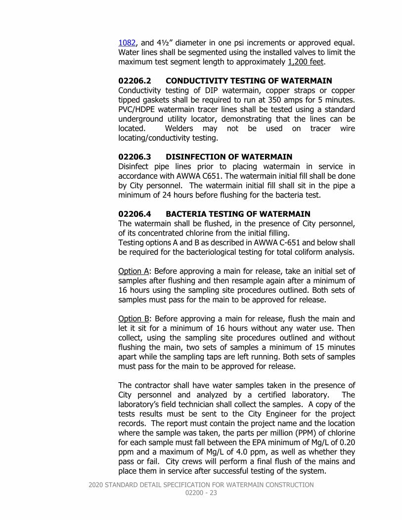
1082, and 4½” diameter in one psi increments or approved equal. Water lines shall be segmented using the installed valves to limit the maximum test segment length to approximately 1,200 feet. 02206.2 CONDUCTIVITY TESTING OF WATERMAIN Conductivity testing of DIP watermain, copper straps or copper tipped gaskets shall be required to run at 350 amps for 5 minutes. PVC/HDPE watermain tracer lines shall be tested using a standard underground utility locator, demonstrating that the lines can be located. Welders may not be used on tracer wire locating/conductivity testing. 02206.3 DISINFECTION OF WATERMAIN Disinfect pipe lines prior to placing watermain in service in accordance with AWWA C651. The watermain initial fill shall be done by City personnel. The watermain initial fill shall sit in the pipe a minimum of 24 hours before flushing for the bacteria test. 02206.4 BACTERIA TESTING OF WATERMAIN The watermain shall be flushed, in the presence of City personnel, of its concentrated chlorine from the initial filling. Testing options A and B as described in AWWA C-651 and below shall be required for the bacteriological testing for total coliform analysis. Option A: Before approving a main for release, take an initial set of samples after flushing and then resample again after a minimum of 16 hours using the sampling site procedures outlined. Both sets of samples must pass for the main to be approved for release. Option B: Before approving a main for release, flush the main and let it sit for a minimum of 16 hours without any water use. Then collect, using the sampling site procedures outlined and without flushing the main, two sets of samples a minimum of 15 minutes apart while the sampling taps are left running. Both sets of samples must pass for the main to be approved for release. The contractor shall have water samples taken in the presence of City personnel and analyzed by a certified laboratory. The laboratory’s field technician shall collect the samples. A copy of the tests results must be sent to the City Engineer for the project records. The report must contain the project name and the location where the sample was taken, the parts per million (PPM) of chlorine for each sample must fall between the EPA minimum of Mg/L of 0.20 ppm and a maximum of Mg/L of 4.0 ppm, as well as whether they pass or fail. City crews will perform a final flush of the mains and place them in service after successful testing of the system.

2020 STANDARD DETAIL SPECIFICATION FOR WATERMAIN CONSTRUCTION 02200 - 24
02207 MEASUREMENT AND PAYMENT
All items will be measured separately according to design designation as indicated in the Pay Item name and as may be detailed and defined in the Plans, Specifications, or Special Provisions. Pipe will generally be designated by size (inside diameter or span), strength class, kind or type, and laying condition. Complete-in-place items shall include all component parts thereof as described or required to complete the unit, but excluding any excesses covered by separate Pay Items. Linear measurement of piping will include the running length of any special fittings (tees, bends, gates, etc.) installed within the line of measure between specified terminal points.
02208 WATERMAIN DETAILS PLATES
W-1 through W-7

2020 STANDARD DETAIL SPECIFICATION FOR WATERMAIN CONSTRUCTION 02200 - 25

2020 STANDARD DETAIL SPECIFICATION FOR WATERMAIN CONSTRUCTION 02200 - 26
2020 STANDARD DETAIL SPECIFICATION FOR WATERMAIN CONSTRUCTION 02200 - 27

2020 STANDARD DETAIL SPECIFICATION FOR WATERMAIN CONSTRUCTION 02200 - 28

2020 STANDARD DETAIL SPECIFICATION FOR WATERMAIN CONSTRUCTION 02200 - 29

2020 STANDARD DETAIL SPECIFICATION FOR WATERMAIN CONSTRUCTION 02200 - 30
2020 STANDARD DETAIL SPECIFICATION FOR WATERMAIN CONSTRUCTION 02200 - 31